JP6818700B2 - Connector engagement sensing mechanism - Google Patents
Connector engagement sensing mechanism Download PDFInfo
- Publication number
- JP6818700B2 JP6818700B2 JP2017568219A JP2017568219A JP6818700B2 JP 6818700 B2 JP6818700 B2 JP 6818700B2 JP 2017568219 A JP2017568219 A JP 2017568219A JP 2017568219 A JP2017568219 A JP 2017568219A JP 6818700 B2 JP6818700 B2 JP 6818700B2
- Authority
- JP
- Japan
- Prior art keywords
- sensor
- ferrule
- connector assembly
- connector
- housing
- Prior art date
- Legal status (The legal status is an assumption and is not a legal conclusion. Google has not performed a legal analysis and makes no representation as to the accuracy of the status listed.)
- Active
Links
- 239000000523 sample Substances 0.000 claims description 66
- 239000013307 optical fiber Substances 0.000 claims description 33
- 230000008859 change Effects 0.000 claims description 31
- 238000006073 displacement reaction Methods 0.000 claims description 17
- 230000002093 peripheral effect Effects 0.000 claims description 11
- 230000004044 response Effects 0.000 claims description 10
- 230000008878 coupling Effects 0.000 claims description 3
- 238000010168 coupling process Methods 0.000 claims description 3
- 238000005859 coupling reaction Methods 0.000 claims description 3
- 230000003287 optical effect Effects 0.000 description 117
- 230000013011 mating Effects 0.000 description 41
- 239000000835 fiber Substances 0.000 description 33
- 230000000712 assembly Effects 0.000 description 24
- 238000000429 assembly Methods 0.000 description 24
- 238000000034 method Methods 0.000 description 18
- 238000005516 engineering process Methods 0.000 description 15
- RYGMFSIKBFXOCR-UHFFFAOYSA-N Copper Chemical compound [Cu] RYGMFSIKBFXOCR-UHFFFAOYSA-N 0.000 description 11
- 239000004593 Epoxy Substances 0.000 description 10
- 230000005693 optoelectronics Effects 0.000 description 8
- 230000000274 adsorptive effect Effects 0.000 description 7
- 239000000126 substance Substances 0.000 description 7
- 239000000853 adhesive Substances 0.000 description 6
- 230000001070 adhesive effect Effects 0.000 description 6
- 230000019491 signal transduction Effects 0.000 description 6
- 238000003780 insertion Methods 0.000 description 5
- 230000037431 insertion Effects 0.000 description 5
- 239000007787 solid Substances 0.000 description 4
- 238000005452 bending Methods 0.000 description 3
- 230000005540 biological transmission Effects 0.000 description 3
- 239000000463 material Substances 0.000 description 3
- 230000011664 signaling Effects 0.000 description 3
- XEEYBQQBJWHFJM-UHFFFAOYSA-N Iron Chemical compound [Fe] XEEYBQQBJWHFJM-UHFFFAOYSA-N 0.000 description 2
- PXHVJJICTQNCMI-UHFFFAOYSA-N Nickel Chemical compound [Ni] PXHVJJICTQNCMI-UHFFFAOYSA-N 0.000 description 2
- 238000004026 adhesive bonding Methods 0.000 description 2
- -1 but not limited to Substances 0.000 description 2
- 239000003990 capacitor Substances 0.000 description 2
- 230000008602 contraction Effects 0.000 description 2
- 239000003989 dielectric material Substances 0.000 description 2
- 125000003700 epoxy group Chemical group 0.000 description 2
- 239000011810 insulating material Substances 0.000 description 2
- 229920000647 polyepoxide Polymers 0.000 description 2
- 230000008054 signal transmission Effects 0.000 description 2
- 230000009471 action Effects 0.000 description 1
- 230000004888 barrier function Effects 0.000 description 1
- 230000000903 blocking effect Effects 0.000 description 1
- 239000000919 ceramic Substances 0.000 description 1
- 230000006835 compression Effects 0.000 description 1
- 238000007906 compression Methods 0.000 description 1
- 239000000356 contaminant Substances 0.000 description 1
- 238000002788 crimping Methods 0.000 description 1
- 238000013500 data storage Methods 0.000 description 1
- 230000002950 deficient Effects 0.000 description 1
- 238000001514 detection method Methods 0.000 description 1
- 230000000694 effects Effects 0.000 description 1
- 238000009429 electrical wiring Methods 0.000 description 1
- 230000007613 environmental effect Effects 0.000 description 1
- 230000004907 flux Effects 0.000 description 1
- 239000011521 glass Substances 0.000 description 1
- 230000005484 gravity Effects 0.000 description 1
- 230000001939 inductive effect Effects 0.000 description 1
- 230000002452 interceptive effect Effects 0.000 description 1
- 229910052742 iron Inorganic materials 0.000 description 1
- 239000002184 metal Substances 0.000 description 1
- 229910052751 metal Inorganic materials 0.000 description 1
- 229910052759 nickel Inorganic materials 0.000 description 1
- 230000000717 retained effect Effects 0.000 description 1
Images


Classifications
-
- G—PHYSICS
- G02—OPTICS
- G02B—OPTICAL ELEMENTS, SYSTEMS OR APPARATUS
- G02B6/00—Light guides; Structural details of arrangements comprising light guides and other optical elements, e.g. couplings
- G02B6/24—Coupling light guides
- G02B6/36—Mechanical coupling means
- G02B6/38—Mechanical coupling means having fibre to fibre mating means
- G02B6/3807—Dismountable connectors, i.e. comprising plugs
- G02B6/3895—Dismountable connectors, i.e. comprising plugs identification of connection, e.g. right plug to the right socket or full engagement of the mating parts
-
- H—ELECTRICITY
- H01—ELECTRIC ELEMENTS
- H01R—ELECTRICALLY-CONDUCTIVE CONNECTIONS; STRUCTURAL ASSOCIATIONS OF A PLURALITY OF MUTUALLY-INSULATED ELECTRICAL CONNECTING ELEMENTS; COUPLING DEVICES; CURRENT COLLECTORS
- H01R13/00—Details of coupling devices of the kinds covered by groups H01R12/70 or H01R24/00 - H01R33/00
- H01R13/64—Means for preventing incorrect coupling
- H01R13/641—Means for preventing incorrect coupling by indicating incorrect coupling; by indicating correct or full engagement
-
- H—ELECTRICITY
- H01—ELECTRIC ELEMENTS
- H01R—ELECTRICALLY-CONDUCTIVE CONNECTIONS; STRUCTURAL ASSOCIATIONS OF A PLURALITY OF MUTUALLY-INSULATED ELECTRICAL CONNECTING ELEMENTS; COUPLING DEVICES; CURRENT COLLECTORS
- H01R13/00—Details of coupling devices of the kinds covered by groups H01R12/70 or H01R24/00 - H01R33/00
- H01R13/66—Structural association with built-in electrical component
- H01R13/665—Structural association with built-in electrical component with built-in electronic circuit
- H01R13/6683—Structural association with built-in electrical component with built-in electronic circuit with built-in sensor
-
- G—PHYSICS
- G02—OPTICS
- G02B—OPTICAL ELEMENTS, SYSTEMS OR APPARATUS
- G02B6/00—Light guides; Structural details of arrangements comprising light guides and other optical elements, e.g. couplings
- G02B6/24—Coupling light guides
- G02B6/36—Mechanical coupling means
- G02B6/38—Mechanical coupling means having fibre to fibre mating means
- G02B6/3807—Dismountable connectors, i.e. comprising plugs
- G02B6/381—Dismountable connectors, i.e. comprising plugs of the ferrule type, e.g. fibre ends embedded in ferrules, connecting a pair of fibres
- G02B6/3817—Dismountable connectors, i.e. comprising plugs of the ferrule type, e.g. fibre ends embedded in ferrules, connecting a pair of fibres containing optical and electrical conductors
-
- G—PHYSICS
- G02—OPTICS
- G02B—OPTICAL ELEMENTS, SYSTEMS OR APPARATUS
- G02B6/00—Light guides; Structural details of arrangements comprising light guides and other optical elements, e.g. couplings
- G02B6/24—Coupling light guides
- G02B6/36—Mechanical coupling means
- G02B6/38—Mechanical coupling means having fibre to fibre mating means
- G02B6/3807—Dismountable connectors, i.e. comprising plugs
- G02B6/381—Dismountable connectors, i.e. comprising plugs of the ferrule type, e.g. fibre ends embedded in ferrules, connecting a pair of fibres
- G02B6/3818—Dismountable connectors, i.e. comprising plugs of the ferrule type, e.g. fibre ends embedded in ferrules, connecting a pair of fibres of a low-reflection-loss type
- G02B6/3821—Dismountable connectors, i.e. comprising plugs of the ferrule type, e.g. fibre ends embedded in ferrules, connecting a pair of fibres of a low-reflection-loss type with axial spring biasing or loading means
-
- G—PHYSICS
- G02—OPTICS
- G02B—OPTICAL ELEMENTS, SYSTEMS OR APPARATUS
- G02B6/00—Light guides; Structural details of arrangements comprising light guides and other optical elements, e.g. couplings
- G02B6/24—Coupling light guides
- G02B6/36—Mechanical coupling means
- G02B6/38—Mechanical coupling means having fibre to fibre mating means
- G02B6/3807—Dismountable connectors, i.e. comprising plugs
- G02B6/381—Dismountable connectors, i.e. comprising plugs of the ferrule type, e.g. fibre ends embedded in ferrules, connecting a pair of fibres
- G02B6/3825—Dismountable connectors, i.e. comprising plugs of the ferrule type, e.g. fibre ends embedded in ferrules, connecting a pair of fibres with an intermediate part, e.g. adapter, receptacle, linking two plugs
-
- G—PHYSICS
- G02—OPTICS
- G02B—OPTICAL ELEMENTS, SYSTEMS OR APPARATUS
- G02B6/00—Light guides; Structural details of arrangements comprising light guides and other optical elements, e.g. couplings
- G02B6/24—Coupling light guides
- G02B6/36—Mechanical coupling means
- G02B6/38—Mechanical coupling means having fibre to fibre mating means
- G02B6/3807—Dismountable connectors, i.e. comprising plugs
- G02B6/389—Dismountable connectors, i.e. comprising plugs characterised by the method of fastening connecting plugs and sockets, e.g. screw- or nut-lock, snap-in, bayonet type
- G02B6/3893—Push-pull type, e.g. snap-in, push-on
-
- H—ELECTRICITY
- H01—ELECTRIC ELEMENTS
- H01R—ELECTRICALLY-CONDUCTIVE CONNECTIONS; STRUCTURAL ASSOCIATIONS OF A PLURALITY OF MUTUALLY-INSULATED ELECTRICAL CONNECTING ELEMENTS; COUPLING DEVICES; CURRENT COLLECTORS
- H01R13/00—Details of coupling devices of the kinds covered by groups H01R12/70 or H01R24/00 - H01R33/00
- H01R13/66—Structural association with built-in electrical component
- H01R13/70—Structural association with built-in electrical component with built-in switch
- H01R13/703—Structural association with built-in electrical component with built-in switch operated by engagement or disengagement of coupling parts, e.g. dual-continuity coupling part
Description
[関連出願の相互参照]
本出願は、参照によりそのすべての開示が本明細書に組み込まれている、2015年7月1日に出願した米国仮特許出願第62/187,673号、2015年8月21日に出願した米国仮特許出願第62/208,443号、2015年9月17日出願した米国仮特許出願第62/220,120号、2015年12月22日に出願した米国仮特許出願第62/271,049号、および2016年5月19日に出願した米国仮特許出願第62/338,697号の出願日の利益を主張する。
[Cross-reference of related applications]
This application is filed on U.S. Provisional Patent Application No. 62 / 187,673, filed on July 1, 2015, August 21, 2015, all of which are incorporated herein by reference. US Provisional Patent Application Nos. 62 / 208,443, US Provisional Patent Application No. 62 / 220,120 filed on September 17, 2015, US Provisional Patent Application No. 62/271, filed on December 22, 2015. Claims the interests of filing dates 049 and US Provisional Patent Application No. 62 / 338,697 filed May 19, 2016.
[発明の分野]
本技術は、一般に光および電気コネクタに関し、詳細にはそのようなデバイスの接続の検知に関する。
[Field of invention]
The present technology relates generally to optical and electrical connectors, and more specifically to detecting the connection of such devices.
光ファイバおよび電線は、それぞれの接続された光ファイバと電線との間で信号を伝送するためにそれぞれの対向する光ファイバおよび電線に光学的にまたは電気的に接続され、それはデータ記憶および伝送デバイスの動作の際に行われることがある。それぞれの対向する光ファイバおよび電線は、それらの端部においてコネクタによって保持される。それぞれの対向する光ファイバと電線との間の接続を確立するために、それぞれの対向する光ファイバおよび電線は、互いに取り付けられ、または両方ともアダプタに取り付けられる。 Fiber optics and wires are optically or electrically connected to their respective opposing fiber optics and wires to transmit signals between each connected fiber optic and wire, which is a data storage and transmission device. May be done during the operation of. Each opposing optical fiber and wire is held by a connector at their ends. To establish a connection between each opposing fiber optic and wire, each opposing fiber optic and wire is attached to each other, or both attached to an adapter.
それぞれの光ファイバコネクタと電線コネクタとの間の接続は、電線コネクタおよびそれによって保持される線がしばしば配線用ハーネスと呼ばれ、光ファイバの「LCコネクタ」の場合のように、しばしばクリックツーロック構成を使用して行われる。この構成により、コネクタが互いにまたは対応するアダプタに接続されているとき、コネクタの引き抜けが防止され、また、コネクタを互いにまたは対応するアダプタに取り付けるユーザに対して引き抜けが防止されている完全接続が行われたと知らせるために触覚フィードバックが提供される。 The connection between each fiber optic connector and the wire connector, the wire connector and the wires held by it, are often referred to as wiring harnesses and are often click-to-lock configurations, as in the case of fiber optic "LC connectors". Is done using. This configuration prevents the connector from being pulled out when the connectors are connected to each other or to the corresponding adapter, and is completely connected to prevent pulling out to the user who attaches the connector to each other or the corresponding adapter. Tactile feedback is provided to inform you that has occurred.
時には、ユーザによって検知されないことがある、コネクタ間の、またはコネクタとアダプタとの間の不完全な接続が行われる。さらに、コネクタの使用により引き起こされた疲労または他のストレスにより、コネクタ間の、またはコネクタとアダプタとの間の機械的接続が弱まり、接続が中断され、または不十分となることがある。そのような不十分なまたは中断された接続により、システム性能が低減され、または完全なシステム故障さえ生じてしまう。 Occasionally, there are incomplete connections between connectors or between connectors and adapters that may not be detected by the user. In addition, fatigue or other stress caused by the use of the connector can weaken the mechanical connection between the connectors or between the connector and the adapter, interrupting or inadequate the connection. Such inadequate or interrupted connections can reduce system performance or even result in complete system failure.
したがって、適切なそれぞれの光ファイバおよび電気配線接続が行われ、維持されていることを検知することが必要とされる。 Therefore, it is necessary to detect that the appropriate fiber optic and electrical wiring connections have been made and maintained.
本技術の態様によれば、コネクタが、相手側コネクタを受けるためのソケットと、ソケットに装着された電気スイッチとを含むことができる。コネクタおよび相手側コネクタは、相手側光または電気コネクタでよいが、それであることに限定されない。相手側コネクタをソケット内の所定の位置において受けるとき、電気スイッチは、相手側コネクタを所定の位置において受けたことを示すために電気信号を生成するか、または生成することを停止するかのいずれかをすることができる。 According to aspects of the present technology, the connector may include a socket for receiving the mating connector and an electrical switch mounted on the socket. The connector and the mating connector may be, but are not limited to, a mating optical or electrical connector. When the mating connector is received at a given position in the socket, the electrical switch either generates or stops generating an electrical signal to indicate that the mating connector has been received at the given position. Can be done.
本技術の別の態様によれば、エネルギー伝達コネクタ組立体が、エネルギー伝達コネクタと、エネルギー伝達コネクタと嵌合するための相手側コネクタとを含むことができる。そのようなエネルギー伝達コネクタは、相手側コネクタを受ける寸法にすることができるソケットと、ソケットに装着することができる電気スイッチとを含むことができる。相手側コネクタをソケット内の所定の位置において受けたとき、電気スイッチは、相手側コネクタを所定の位置において受けたことを示すために電気信号を生成するか、または生成することを停止するかのいずれかをすることができる。 According to another aspect of the art, the energy transfer connector assembly can include an energy transfer connector and a mating connector for mating with the energy transfer connector. Such an energy transfer connector can include a socket that can be sized to receive the mating connector and an electrical switch that can be attached to the socket. When the mating connector is received in place in the socket, the electric switch either generates or stops generating an electrical signal to indicate that the mating connector has been received in place. You can do either.
いくつかの構成において、エネルギー伝達コネクタは、光ファイバまたは導電性素子を保持するための光または電気コネクタでよい。このようにして、いくつかのそのような構成において、相手側コネクタを所定の位置において受け、光ファイバまたは導電性素子を保持しているとき、光ファイバまたは導電性素子は、エネルギー伝達コネクタ内の所定の整合位置にあることができる。 In some configurations, the energy transfer connector may be an optical or electrical connector for holding an optical fiber or conductive element. Thus, in some such configurations, when the mating connector is received in place and holds the optical fiber or conductive element, the optical fiber or conductive element is in the energy transfer connector. It can be in a predetermined alignment position.
本技術の別の態様によれば、エネルギー伝達コネクタが、エネルギー伝達コネクタと嵌合するための相手側コネクタを受ける寸法にすることができるソケットと、センサとを含むことができる。センサはソケットに装着することができる。相手側コネクタをソケット内の所定の位置において受けたとき、センサは、ソケット内の所定の位置における相手側コネクタの受領を検知し、相手側コネクタを所定の位置において受けたことを示すために電気信号を生成するか、または生成することを停止するかのいずれかをすることができる。 According to another aspect of the art, the energy transfer connector can include a socket and a sensor that can be sized to receive a mating connector for mating with the energy transfer connector. The sensor can be mounted in the socket. When the mating connector is received at a given position in the socket, the sensor detects the receipt of the mating connector at a given position in the socket and is charged to indicate that the mating connector has been received at the given position. You can either generate a signal or stop producing it.
いくつかの構成において、エネルギー伝達コネクタは、エネルギー信号伝達コネクタでよい。いくつかのそのような構成において、エネルギー信号伝達コネクタは、データに対応する光信号を伝達するそれぞれの光ファイバまたはデータに対応する電気信号を伝達する導電性素子を保持するための光または電気信号伝達コネクタでよい。そのようなデータは、データセンターにおいて見出すことができるような機器を含むがそれに限定されない、ネットワークまたはサーバ機器に、またはネットワークまたはサーバ機器から転送されたデータでよい。 In some configurations, the energy transfer connector may be an energy signal transfer connector. In some such configurations, the energy signal transfer connector is an optical or electrical signal to hold the respective optical fiber that transmits the optical signal corresponding to the data or the conductive element that transmits the electrical signal corresponding to the data. It may be a transmission connector. Such data may be data transferred to or from a network or server device, including but not limited to devices that can be found in the data center.
いくつかのそのような構成において、エネルギー信号伝達コネクタは、光ファイバまたは導電性素子を保持するための光または電気コネクタでよい。このようにして、いくつかのそのような構成において、相手側コネクタを所定の位置において受け、光ファイバまたは導電性素子を保持しているとき、光ファイバまたは導電性素子は、エネルギー伝達コネクタ内の所定の整合位置にあることができる。 In some such configurations, the energy signal transfer connector may be an optical or electrical connector for holding an optical fiber or conductive element. Thus, in some such configurations, when the mating connector is received in place and holds the optical fiber or conductive element, the optical fiber or conductive element is in the energy transfer connector. It can be in a predetermined alignment position.
いくつかの構成において、センサは電気光学センサでよい。電気光学センサは、位置センサによって送信された光を物体が遮断したとき信号を生成する位置センサ、または物体が光電センサからである距離を少なくとも検知し、物体の有無を検知する光電センサでよいが、それであることに限定されない。 In some configurations, the sensor may be an electro-optical sensor. The electro-optical sensor may be a position sensor that generates a signal when an object blocks the light transmitted by the position sensor, or a photoelectric sensor that detects at least the distance that the object is from the photoelectric sensor and detects the presence or absence of the object. , Not limited to that.
いくつかの構成において、センサは電気スイッチでよい。このようにして、相手側コネクタをソケット内の所定の位置において受けたとき、電気スイッチは、相手側コネクタによって接触されて、相手側コネクタを所定の位置において受けたことを示すために電気スイッチにより電気信号を生成するか、または生成することを停止するかのいずれかをすることができる。 In some configurations, the sensor may be an electric switch. In this way, when the mating connector is received at a predetermined position in the socket, the electrical switch is contacted by the mating connector and by the electrical switch to indicate that the mating connector has been received at the predetermined position. It can either generate an electrical signal or stop producing it.
本技術の別の態様によれば、エネルギー伝達コネクタ組立体が、エネルギー伝達コネクタと、エネルギー伝達コネクタと嵌合するための相手側コネクタとを含むことができる。そのようなエネルギー伝達コネクタは、相手側コネクタを受ける寸法にすることができるソケットと、ソケットに装着することができるセンサとを含むことができる。相手側コネクタをソケット内の所定の位置において受けたとき、センサは、ソケット内の所定の位置における相手側コネクタの受領を検知し、相手側コネクタを所定の位置において受けたことを示すために電気信号を生成するか、または生成することを停止するかのいずれかをすることができる。 According to another aspect of the art, the energy transfer connector assembly can include an energy transfer connector and a mating connector for mating with the energy transfer connector. Such an energy transfer connector can include a socket that can be sized to receive the mating connector and a sensor that can be attached to the socket. When the mating connector is received at a given position in the socket, the sensor detects the receipt of the mating connector at a given position in the socket and is charged to indicate that the mating connector has been received at the given position. You can either generate a signal or stop producing it.
いくつかの構成において、エネルギー伝達コネクタは、光ファイバまたは導電性素子を保持するための光または電気コネクタでよい。このようにして、いくつかのそのような構成において、相手側コネクタを所定の位置において受け、光ファイバまたは導電性素子を保持しているとき、光ファイバまたは導電性素子は、エネルギー伝達コネクタ内の所定の整合位置にあることができる。 In some configurations, the energy transfer connector may be an optical or electrical connector for holding an optical fiber or conductive element. Thus, in some such configurations, when the mating connector is received in place and holds the optical fiber or conductive element, the optical fiber or conductive element is in the energy transfer connector. It can be in a predetermined alignment position.
本技術の別の態様によれば、エネルギー伝達コネクタ組立体は、エネルギー伝達コネクタと嵌合するために相手側コネクタを受ける寸法にされたソケットと、ソケットと結合するように構成された枠に装着されたセンサとを含むことができる。枠がソケットに結合され、相手側コネクタをソケット内の所定の位置において受けたとき、センサは、ソケット内の所定の位置における相手側コネクタの受領を検知し、相手側コネクタを所定の位置において受けたことを示すために電気信号を生成するか、または生成することを停止するかのいずれかをすることができる。 According to another aspect of the art, the energy transfer connector assembly is mounted on a socket sized to receive a mating connector for mating with the energy transfer connector and a frame configured to couple with the socket. Can include sensors and connectors. When the frame is coupled to the socket and the mating connector is received at a given position in the socket, the sensor detects receipt of the mating connector at a given position in the socket and receives the mating connector at a given position. You can either generate an electrical signal to indicate that, or stop generating it.
いくつかの構成において、エネルギー伝達コネクタは、光ファイバまたは導電性素子を保持するための光または電気コネクタでよい。このようにして、いくつかのそのような構成において、相手側コネクタを所定の位置において受け、光ファイバまたは導電性素子を保持しているとき、光ファイバまたは導電性素子は、エネルギー伝達コネクタ内の所定の整合位置にあることができる。 In some configurations, the energy transfer connector may be an optical or electrical connector for holding an optical fiber or conductive element. Thus, in some such configurations, when the mating connector is received in place and holds the optical fiber or conductive element, the optical fiber or conductive element is in the energy transfer connector. It can be in a predetermined alignment position.
いくつかの構成において、センサは、ソケットを通してソケット内の所定の位置における相手側コネクタの受領を検知する。 In some configurations, the sensor detects the receipt of the mating connector in place within the socket through the socket.
本技術の別の態様によれば、コネクタ組立体が、ハウジングと、フェルールと、センサとを含むことができる。ハウジングは内腔を有することができる。フェルールは、ハウジングの内腔内で平行移動可能であり得る。センサは、ハウジングの内腔に装着することができ、フェルールの平行移動を検知するように構成することができる。フェルールをそのように検知し次第、センサの電気的特性が、所定の位置までのフェルールの平行移動を示すように変化することができる。 According to another aspect of the art, the connector assembly can include a housing, ferrules, and sensors. The housing can have a lumen. The ferrule can be translated within the lumen of the housing. The sensor can be mounted in the lumen of the housing and can be configured to detect translation of the ferrule. As soon as the ferrule is so detected, the electrical properties of the sensor can change to indicate translation of the ferrule to a given position.
いくつかの構成において、センサは、フェルールの平行移動の間、フェルールに接触するように構成することができるプローブを含むことができる。このようにして、プローブは、フェルールに接触している間、フェルールとともに平行移動することができ、センサの電気的特性は、プローブの平行移動に応じてフェルールが所定の位置まで平行移動したことを示すように変化することができる。そのようなプローブは、静止位置から引っ込む引き込み式プローブでよい。 In some configurations, the sensor can include a probe that can be configured to contact the ferrule during translation of the ferrule. In this way, the probe can translate with the ferrule while in contact with the ferrule, and the electrical characteristics of the sensor indicate that the ferrule has translated to a predetermined position in response to the translation of the probe. It can change as shown. Such a probe may be a retractable probe that retracts from a stationary position.
いくつかの構成において、センサは圧力または変位センサでよい。 In some configurations, the sensor may be a pressure or displacement sensor.
いくつかの構成において、コネクタ組立体は、フェルールに当接することができる弾性素子を含むことができる。そのような構成において、センサは、フェルールの平行移動の間、弾性素子の長さの変化を検知することができる。 In some configurations, the connector assembly can include elastic elements that can abut the ferrule. In such a configuration, the sensor can detect changes in the length of the elastic element during translation of the ferrule.
いくつかの構成において、コネクタ組立体は、フェルール中を通過する一部分を有する光ファイバを含むことができる。そのような構成において、フェルールは、フェルール中を通過する光ファイバの一部分の位置を維持することができる。 In some configurations, the connector assembly can include an optical fiber having a portion that passes through the ferrule. In such a configuration, the ferrule can maintain the position of a portion of the optical fiber passing through the ferrule.
いくつかの構成において、コネクタ組立体はケーブルを含むことができる。ケーブルは、ケーブルの長さに沿って位置決めすることができる第2のセンサを含むことができる。そのような構成において、上に第2のセンサが位置するケーブルの表面が変形したとき、第2のセンサの電気的特性が変化することができる。いくつかのそのような構成において、第2のセンサの電気的特性の変化に対応する電気信号が遠隔電子デバイスに伝導され、少なくとも最小値を有するとき、遠隔電子デバイスによって警告信号を生成することができる。 In some configurations, the connector assembly can include cables. The cable can include a second sensor that can be positioned along the length of the cable. In such a configuration, when the surface of the cable on which the second sensor is located is deformed, the electrical characteristics of the second sensor can change. In some such configurations, the remote electronic device may generate a warning signal when the electrical signal corresponding to the change in electrical properties of the second sensor is conducted to the remote electronic device and has at least a minimum value. it can.
本技術の別の態様によれば、コネクタ組立体が、ハウジングと、フェルールと、第1および第2の導電性接点とを含むことができる。ハウジングは内腔を有することができる。フェルールは、ハウジングの内腔内で平行移動可能であり得る。第1の導電性接点はハウジングに装着することができる。第2の導電性接点はフェルールに装着することができる。第2の導電性接点は、フェルールの平行移動の間、第1の位置と第2の位置との間で移動可能であり得る。第2の導電性接点は、フェルールが平行移動の第1の位置にあるとき第1の導電性接点と導電結合することができ、第2の導電性接点は、フェルールが平行移動の第2の位置にあるとき第1の導電性接点と導電結合しない可能性がある。 According to another aspect of the art, the connector assembly can include a housing, ferrules, and first and second conductive contacts. The housing can have a lumen. The ferrule can be translated within the lumen of the housing. The first conductive contact can be mounted on the housing. The second conductive contact can be attached to the ferrule. The second conductive contact may be movable between the first position and the second position during the translation of the ferrule. The second conductive contact can be conductively coupled to the first conductive contact when the ferrule is in the first position of translation, and the second conductive contact is the second conductive contact in which the ferrule is translated. When in position, it may not be conductively coupled to the first conductive contact.
本技術の別の態様によれば、システムが、回路と、ハウジングと、フェルールと、第1および第2の導電性接点とを含むことができる。回路は、制御信号を周辺構成要素に提供するように構成することができる。ハウジングは内腔を有することができる。フェルールは、ハウジングの内腔内で平行移動可能であり得る。第1の導電性接点はハウジングに装着することができる。第2の導電性接点は、フェルールの端部上でフェルールに装着することができる。第2の導電性接点は、フェルールの平行移動の間、第1の位置と第2の位置との間で移動可能であり得る。第2の導電性接点は、フェルールが平行移動の第1の位置にあるとき、第1の導電性接点と導電結合することができ、第2の導電性接点は、フェルールが平行移動の第2の位置にあるとき、第1の導電性接点と導電結合しない可能性がある。 According to another aspect of the art, the system can include circuits, housings, ferrules, and first and second conductive contacts. The circuit can be configured to provide control signals to peripheral components. The housing can have a lumen. The ferrule can be translated within the lumen of the housing. The first conductive contact can be mounted on the housing. The second conductive contact can be attached to the ferrule on the edge of the ferrule. The second conductive contact may be movable between the first position and the second position during the translation of the ferrule. The second conductive contact can be conductively coupled to the first conductive contact when the ferrule is in the first position of translation, and the second conductive contact is the second where the ferrule is translated. When in the position of, there is a possibility that the first conductive contact will not be conductively coupled.
いくつかの構成において、回路は論理回路でよく、いくつかのそのような構成において、システムは論理システムでよい。 In some configurations, the circuit may be a logic circuit, and in some such configurations, the system may be a logic system.
いくつかの構成において、第1の導電性接点と第2の導電性接点とが導電結合されたとき、回路は、制御信号を周辺構成要素に提供しない可能性がある。 In some configurations, when the first conductive contact and the second conductive contact are conductively coupled, the circuit may not provide a control signal to the peripheral components.
いくつかの構成において、第1の導電性接点と第2の導電性接点とが導電結合されたとき、回路は、制御信号を周辺構成要素に提供することができる。 In some configurations, the circuit can provide a control signal to the peripheral components when the first conductive contact and the second conductive contact are conductively coupled.
本技術の別の態様によれば、コネクタ組立体が、アダプタと、ハウジングと、フェルールと、センサとを含むことができる。ハウジングは、アダプタによって受けることができ、内腔を有することができる。フェルールは、ハウジングの内腔内で平行移動可能であり得る。センサは、ハウジング上に、またはアダプタ上に装着することができる。センサは、フェルールの平行移動を検知するように構成することができる。センサの電気的特性が、所定の位置までのフェルールの平行移動を示すように変化することができる。 According to another aspect of the art, the connector assembly can include an adapter, a housing, a ferrule, and a sensor. The housing can be received by an adapter and can have a lumen. The ferrule can be translated within the lumen of the housing. The sensor can be mounted on the housing or on the adapter. The sensor can be configured to detect translation of the ferrule. The electrical properties of the sensor can be varied to indicate translation of the ferrule to a given position.
いくつかの構成において、センサは、ハウジングの壁の外部部分上に装着することができ、それにおいて、壁がハウジングの内腔を画定し、外部部分が内腔からの壁の反対側にある。 In some configurations, the sensor can be mounted on the outer part of the wall of the housing, in which the wall defines the lumen of the housing and the outer part is on the opposite side of the wall from the lumen.
いくつかの構成において、センサは、センサをハウジング上に装着したときアダプタに、またはセンサをアダプタ上に装着したときハウジングに接触するように構成することができるプローブを含むことができる。このようにして、プローブは、センサをハウジング上に装着したときアダプタに対して、またはセンサをアダプタ上に装着したときにハウジングとともに平行移動する、または平行移動される可能性がある。そのようなプローブの平行移動は、そのようなプローブのそれぞれのアダプタまたはハウジングとの接触の間、フェルールの平行移動に比例することができる。センサの電気的特性は、プローブの平行移動に応じてフェルールが所定の位置まで平行移動したことを示すように変化することができる。 In some configurations, the sensor can include a probe that can be configured to contact the adapter when the sensor is mounted on the housing or the housing when the sensor is mounted on the adapter. In this way, the probe may translate or translate with the adapter when the sensor is mounted on the housing, or with the housing when the sensor is mounted on the adapter. The translation of such a probe can be proportional to the translation of the ferrule during contact with each adapter or housing of such probe. The electrical properties of the sensor can be varied to indicate that the ferrule has been translated to a predetermined position in response to the translation of the probe.
いくつかの構成において、センサは変位センサでよい。いくつかの他の構成において、センサは圧力センサでよい。 In some configurations, the sensor may be a displacement sensor. In some other configurations, the sensor may be a pressure sensor.
いくつかの構成において、コネクタ組立体は、ハウジングから延びることができる突起をさらに含むことができる。いくつかのそのような構成において、センサは、センサをハウジング上に装着するとき突起上に装着することができ、または、プローブは、センサをアダプタ上に装着するとき突起に接触するように構成することができる。 In some configurations, the connector assembly may further include protrusions that can extend from the housing. In some such configurations, the sensor can be mounted on the protrusion when mounting the sensor on the housing, or the probe is configured to contact the protrusion when mounting the sensor on the adapter. be able to.
いくつかの構成において、ハウジングは、本体と、本体から延びることができる突起とを含むことができる。センサは、本体と、本体および突起のいずれかの上の突起との間に装着することができる。センサは、センサを本体上に装着するとき突起に、またはセンサを突起上に装着するとき本体に接触するように構成することができるプローブを含むことができる。このようにして、プローブは、センサを本体上に装着したとき突起とともに、またはセンサを突起上に装着したとき本体に対して平行移動する、または平行移動される可能性がある。そのようなプローブの平行移動は、それぞれの突起または本体とのそのような接触の間、フェルールの平行移動に比例することができる。センサの電気的特性は、プローブの平行移動に応じてフェルールが所定の位置まで平行移動したことを示すように変化することができる。 In some configurations, the housing can include a body and protrusions that can extend from the body. The sensor can be mounted between the body and a protrusion on either the body or the protrusion. The sensor can include a probe that can be configured to contact the protrusions when the sensor is mounted on the body or the body when the sensor is mounted on the body. In this way, the probe may be translated or translated with respect to the body when the sensor is mounted on the body or with the protrusion when the sensor is mounted on the body. The translation of such a probe can be proportional to the translation of the ferrule during such contact with each protrusion or body. The electrical properties of the sensor can be varied to indicate that the ferrule has been translated to a predetermined position in response to the translation of the probe.
いくつかのそのような構成において、突起は、センサが本体上にあるとき、本体に蝶番式に接続することができる。いくつかの他のそのような構成において、突起は本体と一体でよい。 In some such configurations, the protrusions can be hinged to the body when the sensor is on the body. In some other such configurations, the protrusion may be integral with the body.
いくつかの構成において、コネクタ組立体は、ハウジングから延びることができる突起をさらに含むことができる。センサは、センサをハウジング上に装着するとき突起上に装着することができ、または、センサは、センサをアダプタ上に装着するとき突起に接触するように構成することができる。フェルールの最小距離の平行移動の間、センサは、センサをハウジング上に装着したときアダプタからの力によって押圧することができ、または、突起は、センサをアダプタ上に装着したときセンサに対して力によって押圧することができる。センサの電気的特性は、センサに作用する力に応じてフェルールが所定の位置まで平行移動したことを示すように変化することができる。 In some configurations, the connector assembly may further include protrusions that can extend from the housing. The sensor can be mounted on the protrusion when the sensor is mounted on the housing, or the sensor can be configured to contact the protrusion when the sensor is mounted on the adapter. During the minimum distance translation of the ferrule, the sensor can be pressed by the force from the adapter when the sensor is mounted on the housing, or the protrusions force against the sensor when the sensor is mounted on the adapter. Can be pressed by. The electrical properties of the sensor can be varied to indicate that the ferrule has been translated to a predetermined position in response to the force acting on the sensor.
いくつかの構成において、ハウジングは、本体と、本体から延びる突起とを含むことができる。センサは、本体と突起との間で本体と突起のいずれかの上に装着することができる。センサは、センサを突起上に装着するとき本体に接触するように構成することができ、または、センサは、センサを本体上に装着するとき突起に接触するように構成することができる。フェルールの最小距離の平行移動の間、センサは、センサを突起上に装着したとき本体に対して力によって押圧することができ、または、突起は、センサを本体上に装着したときセンサに対して力によって押圧することができる。センサの電気的特性は、センサに作用する力に応じてフェルールが所定の位置まで平行移動したことを示すように変化することができる。 In some configurations, the housing can include a body and protrusions extending from the body. The sensor can be mounted between the body and the protrusion on either the body or the protrusion. The sensor can be configured to contact the body when the sensor is mounted on the body, or the sensor can be configured to contact the body when the sensor is mounted on the body. During the minimum distance translation of the ferrule, the sensor can be pressed by force against the body when the sensor is mounted on the body, or the protrusion is against the sensor when the sensor is mounted on the body. It can be pressed by force. The electrical properties of the sensor can be varied to indicate that the ferrule has been translated to a predetermined position in response to the force acting on the sensor.
いくつかのそのような構成において、突起は、センサが本体上にあるとき、本体に蝶番式に接続することができる。いくつかの他のそのような構成において、突起は本体と一体でよい。 In some such configurations, the protrusions can be hinged to the body when the sensor is on the body. In some other such configurations, the protrusion may be integral with the body.
本発明の主題およびその様々な利点のより完全な理解は、以下の添付の図面を参照する以下の詳細な説明の参照によって実現することができる。 A more complete understanding of the subject matter of the present invention and its various advantages can be achieved by reference to the following detailed description with reference to the accompanying drawings below.
図1および2を参照すると、1つの光ファイバから別の光ファイバへの光信号の伝達を容易にするための例示的なエネルギー信号伝達組立体として光学組立体100が、雌型コネクタ組立体110と雄型コネクタ140とを含むことができ、図示するようにそれらは、「LCコネクタ」などの光ファイバの整合のためのコネクタでよい。雌型コネクタ組立体110は、第1のソケット112が光ファイバ構成要素(図示せず)を受けることができ、第2のソケット114が雄型コネクタ140の相手側端部141を受けることができる、第1のソケット112と、第1のソケット112に対向し、第1のソケット112と壁を共有する第2のソケット114とを含むことができる。雌型コネクタ組立体110は、複数の光ファイバ構成要素および雄型コネクタ140を受けるために、図示する例におけるように、第1および第2のソケット112、114の複数の組を含むことができる。
Referring to FIGS. 1 and 2, the
雌型コネクタ組立体110は、図示するように、第2のソケット114内の表面上に装着することができるスイッチ130をさらに含むことができる。スイッチ130は、モジュールベース132とトリガ134とを有するトグル型スイッチとして示す。しかし、押しボタンスイッチおよび磁気作動スイッチまたは他の機械的接触スイッチを含むがそれらに限定されない他のスイッチをトグル型スイッチの代わりに使用することができる。
The
雌型コネクタ組立体110は、雌型コネクタ組立体110の第2のソケット114が相手側端部を受けるとき、雄型コネクタ140の相手側端部141から延びる雄型突起142を受けるための内腔118を画定する雌型突起116を含むことができる。図2に最もよく示すように、雄型突起142を雌型突起116内で受けたとき、雌型突起は、雄型コネクタ140の凹部144内で受けることができる。雄型突起142と雌型突起116との相互接続により、雄型コネクタ140の雄型突起142の内腔145内に延びる光ファイバ180は、前に本明細書に説明した第1のソケット112内に受けることができる光ファイバ構成要素内の光ファイバの端部と整合させるために雌型コネクタ組立体110に位置決めすることができる。図示する例におけるように、雌型コネクタ組立体110は、光ファイバ構成要素の相手側端部から延びる雄型突起を受けるための内腔を画定する第2の雌型突起119を含むことができ、光ファイバ構成要素の相手側端部を通って、光ファイバ構成要素の光ファイバが光ファイバ180との整合のために延びることができる。
The
雄型コネクタ140は、相手側端部141から延びる下部クリップ146と、雄型コネクタ140の前部149から延びる上部クリップ148とを含むことができる。上部クリップ148は、雄型コネクタの残りの部分から離れる方向に下部クリップ146の移動を制限し、ならびに下部クリップの望ましくない屈曲から保護する障壁を提供するように動作することができる。下部クリップ146は、雄型コネクタ140を雌型コネクタ110の第2のソケット114内に受けたとき、後面がスイッチ130のトリガ134に接触して、トリガに後方に移動させるようにすることができるように後面150を含むことができる。図示するように、スイッチ130は、雄型コネクタ140が所定の挿入距離に到達したとき、トリガ134が常時開接点を閉じ、または代替として常時閉接点を開く位置まで移動されるように第2のソケット114内に位置決めすることができる。このようにして、スイッチ130は、ライトパネル(図示せず)などの遠隔電子デバイスに伝達することができる電気信号などであるが、それに限定されない信号を生成することができ、または電子デバイスに結合された信号受信機に経路指定するための信号を生成および送信することができ、または代替として、雄型コネクタ140を雌型コネクタ110内に適切に受けたとの指示を提供するためにスイッチが開いているとき、電気信号などであるが、それに限定されない信号を生成または送信することを停止することができる。いくつかの構成において、そのようなスイッチは、スイッチを閉じたとき変化することができる抵抗、容量、またはインダクタンスなどの可変電気的特性を有することができる。そのような構成において、スイッチ内の抵抗、容量、またはインダクタンスの変化は、電気的特性の変化に対応し、線を介してなど、または信号伝達手段のようにスイッチから伝達された電気信号を受信する遠隔受信機によって認識することができる。
The
いくつかの構成において、スイッチ130は、第2のソケット114の一部分内に延びる線に接続することができ、他の構成において、スイッチ130は、スイッチに隣接した導電性端子(図示せず)と接触することができる。さらに他の構成において、スイッチ130は、図3〜6の実施形態における代替構成に示すものなどのフレックスリボンケーブルまたは可撓性回路基板などであるがそれに限定されない、当業者には周知の他の構成において電気的に接続することができる。
In some configurations, the
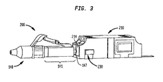
次に図3〜6を参照すると、光学組立体200が、雌型コネクタ組立体210と雄型コネクタ140とを含むことができる。雌型コネクタ組立体210は、雌型コネクタ組立体110と実質的に同様でよいが、本明細書に説明するある顕著な例外を有する。雌型コネクタ組立体110は、センサ230を含むことができ、センサ230は、スイッチ130の代わりに、またはスイッチ130に加えて、電気光学センサでよい。図5に最もよく示すように、そのような電気光学センサは、位置センサ、例えば、図5の矢印205および206で表される光を送信および受信し、ならびに電気信号などであるがそれに限定されない信号を生成する、OSRAM SFH 7741近接センサ、SHARP GP2AP030A00F周囲光センサ付き近接センサ、SHARP GP2AP002S00F近接センサ、GP2AP002A00F統合周囲光センサ付き近接センサ、およびVISHAY VCNL4040赤外線放射体、I2Cインターフェース、および割り込み機能付き完全統合近接および周囲光センサのいずれかでよい。そのような信号は、ライトパネル(図示せず)などの遠隔電子デバイス、または電子デバイスに結合された信号受信機に経路指定するための信号を生成および送信し、または代替として、センサによって送信された光を物体が遮断したとき、電気信号などであるがそれに限定されない信号を生成または送信することを停止する位置センサに伝達することができる。いくつかの構成において、そのような位置センサは、センサによって光を受信したとき、または受信することを停止したとき、変化することができる抵抗、容量、またはインダクタンスなどの可変電気的特性を有することができる。そのような構成において、センサ内の抵抗、容量、またはインダクタンスの変化は、電気的特性の変化に対応し、線を介してなど、または信号伝達手段のように位置センサから伝達された電気信号を受信する遠隔受信機によって認識することができる。
Next, referring to FIGS. 3 to 6, the
図示する例におけるように、センサ230は、雌型コネクタ組立体210の外部に装着することができる。この構成において、雌型コネクタ組立体210は、第2のソケット214の側壁を貫通する穴部221、222の対を有することができる。さらに図5を参照すると、センサ230によって送信される光は、穴部221中を通過することができ、センサ230によって受信される光は、穴部222中を通過することができる。
As shown in the illustrated example, the
図6に示すように、フレックスリボンケーブルでよいが、それであることに限定されないケーブル225、または図示するように可撓性回路基板は、センサ230に電気的に接続し、センサ230から延びることができる。このようにして、ケーブル225は、センサが光を送信し、受信した光を検知し、およびセンサによって送信された光を物体が遮断したとき信号を生成し、または生成および送信するようにセンサ230を作動させるために電力を提供することができる。
As shown in FIG. 6, a flex ribbon cable, but not limited to, a
図3および4を参照すると、雄型コネクタ140の相手側端部141は、雌型コネクタ組立体210の穴部222と整合する雌型コネクタ組立体210の第2のソケット214内のある深さまで後端147を受けたとき、センサ230によって送信された光を後端が遮断することができるように後端147を含むことができる。このようにして、センサ230は、雌型コネクタ組立体210の第2のソケット214における雄型コネクタ140の存在を検知することができる。雄型コネクタ140の存在を検知したとき、センサ230は、ライトパネル(図示せず)などの遠隔電子デバイスに伝達することができる電気信号などであるが、それに限定されない、ケーブル225に沿って搬送される信号を生成し、または遠隔信号受信機に経路指定するための信号を生成および送信することができ、または代替として、センサ230は、前に本明細書に説明したように光学組立体100のスイッチ130と同様のやり方で、電気信号などであるが、それに限定されない信号を生成または送信することを停止することができる。
With reference to FIGS. 3 and 4, the
図7を参照すると、光学組立体300が、雌型コネクタ組立体310と雄型コネクタ140とを含むことができる。雌型コネクタ組立体310は、センサ230が雌型コネクタ組立体310の第2のソケット314の側壁を貫通して延びる穴部と整合されるように、雌型コネクタ組立体のセンサ230を雌型コネクタ組立体310の外部上に位置決めすることができることを除いて、雌型コネクタ組立体210と実質的に同様でよい。そのような構成において、センサ230が光を検知する、第2のソケット314の側壁を貫通する穴部は、下部クリップ146が雌型コネクタ組立体310内に雄型コネクタ140が完全に挿入された静止位置にあるとき、下部クリップ146と整合するように位置決めすることができる。したがって、センサ230によって送信された光の遮断は、下部クリップ146が静止位置にあるとき、センサ230によって検知することができ、その結果として、センサ230は、信号が光学組立体200によって生成されるか、または光学組立体200によって生成されることを停止するかのいずれかと同じように、ケーブル225に沿って搬送される信号を生成し、またはケーブル225に沿って搬送される信号を生成することを停止することができる。下部クリップ146が、雄型コネクタ140が完全に挿入された静止位置にあるとき、センサ230は、したがって、雄型コネクタ140の存在ならびに雌型コネクタ組立体310内への雄型コネクタ140の完全挿入を検知する。
With reference to FIG. 7, the
図8を参照すると、光学組立体が、雌型コネクタ組立体410と、雄型コネクタ140などの雄型コネクタとを含むことができる。雌型コネクタ組立体410は、センサ230を構造体460に固定することができることを除いて雌型コネクタ組立体210と実質的に同様でよく、構造体460は、雌型コネクタ組立体410とは分離可能である枠でよいが、枠であることに限定されない。図示するように、ケーブル225は、ケーブルに剛性を追加するために構造体460に、接着剤によってなどであるが、それに限定されないで、固定することができる。
With reference to FIG. 8, the optical assembly can include a
構造体460は、センサ230が雌型コネクタ組立体410の第2のソケット214の側壁を貫通して延びる穴部222と整合されるように、雌型コネクタ組立体410に対して位置決めし、または雌型コネクタ組立体410に結合さえすることができる。このようにして、雄型コネクタ140の後端147を雌型コネクタ210の穴部222と整合する雌型コネクタ組立体410の第2のソケット214内のある深さまで受けたとき、後端は、センサ230によって送信された光を遮断する。このようにして、センサ230は、雌型コネクタ組立体410の第2のソケット214における雄型コネクタ140の存在を検知することができる。雄型コネクタ140の存在を検知したとき、センサ230は、ライトパネル(図示せず)などの遠隔電子デバイスに伝達することができる電気信号などであるが、それに限定されない、ケーブル225に沿って搬送される信号を生成し、または遠隔信号受信機に経路指定するための信号を生成および送信することができ、または代替として、センサ230は、電気信号などであるが、それに限定されない信号を生成または送信することを停止することができる。
The
光学組立体200および400の代替構成(図示せず)において、雄型コネクタ140を雌型コネクタの第2のソケット内に完全に挿入したとき、雄型コネクタ140の後端147が、後端が整合することができる第1の穴部と整合することができるように、センサ230、およびセンサによって送信および受信された光との整合のための対応する穴部は、雌型コネクタ組立体の第2のソケットの外部において位置決めすることができる。したがって、センサ230によって送信された光の遮断は、雄型コネクタ140を雌型コネクタの第2のソケット内に完全に挿入したとき、センサ230によって検知することができ、その結果として、センサ230は、信号が光学組立体200によって生成することができるか、または光学組立体200によって生成されることを停止することができるかのいずれかと同じように、ケーブル225に沿って搬送される信号を生成することができ、またはケーブル225に沿って搬送される信号を生成することを停止することができる。そのような構成において、センサ230は、したがって、雄型コネクタ140の存在ならびに雌型コネクタ組立体内への雄型コネクタ140の完全な挿入を検知する。
In an alternative configuration (not shown) of the
次に図9を参照すると、センサとケーブル225との間の接続部を覆うためにカバー570をセンサ230などのセンサの上に配置し、雌型コネクタ組立体210などの雌型コネクタ組立体、または本明細書に開示する他の雌型コネクタ組立体のいずれかに取り付けることができる。このようにして、カバー570は、汚染物質がセンサとケーブル225との間の信号伝送の回路を損傷するのを、または信号伝送を妨害するのを防止することができる。
Next, referring to FIG. 9, a
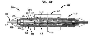
次に図10Aおよび10Bを参照すると、光学組立体600が、第1のコネクタ組立体610と、第2のコネクタ組立体640とを含むことができ、それにおいて、第1および第2のコネクタ組立体は、互いに、ならびに第1および第2のコネクタ組立体を挿入し、互いに適切に位置合わせすることができるアダプタ650と当接することにより係合可能であり得る。第1および第2のコネクタ組立体610、640のそれぞれは、ハウジング611と、内側および外側フェルール部分617Aおよび617Bならびに内側および外側フェルール部分のそれぞれを通って延び、外側フェルール部分によって位置に保持される光ファイバ1を有することができるファイバおよびフェルール組立体616と,コイルバネでよいがそれであることに限定されない弾性素子621と、弾性素子ストッパ623とを含むことができる。図示する例におけるように、第1および第2のコネクタ組立体610、640のそれぞれは、任意選択で、バッファ管および撚糸組立体627と、バッファ管および撚糸組立体ならびに弾性素子ストッパ623の後端部を圧着することができる圧着リング628と、弾性ストッパ623の後端部、バッファ管および撚糸組立体627、ならびに圧着リング628のいずれかまたはすべてを覆うことができるブーツ629とを含むことができる。
Next, referring to FIGS. 10A and 10B, the
図示するように、ハウジング611は、その直径にわたる隔壁612を含むことができ、隔壁612を通ってファイバおよびフェルール組立体616の外側フェルール部分617Bが延びることができる。このようにして、隔壁612は、隔壁がハウジングによって画定された中心軸に沿って外側フェルール部分、したがってファイバおよびフェルール組立体616のファイバ1の位置合せを助けるように、外側フェルール部分617Bの中央部分を保持する。
As shown, the
内側フェルール部分617Aは、ハウジング611の隔壁612の内側のハウジング611のハウジング内腔613を通って延びることができ、それにおいて、内側フェルール部分617Aの前方区分は、内側フェルール部分がハウジング内腔と摺動係合し、ハウジングに対して半径方向および軸方向位置に固定されるように、ハウジング内腔と同じ、または実質的に同じである外径を有することができる。
The
セラミック、ガラス、および硬質プラスチックのいずれかで製作してよいが、それらであることに限定されない、外側フェルール部分617Bの後端部が、内側フェルール部分617Aの前方区分内に延びることができる。このようにして、内側フェルール部分617Aは、内側フェルール部分が、ハウジング611の隔壁612とともに、ハウジングによって画定された中心軸に沿って外側フェルール部分、したがってファイバおよびフェルール組立体616のファイバ1の位置合せを助けるように、外側フェルール部分617Bの中央部分を保持することができる。
The rear end of the
弾性素子ストッパ623は、ハウジング611を貫通して延びることができ、弾性素子ストッパ623の縦軸から半径方向に延びる前方フランジ624を有することができる。図示するように,前方フランジ624は、弾性素子ストッパ623の前方フランジの前端部が前方フランジの後端部よりも小さい直径を有するように、面取りをすることができる。前方フランジ624は、弾性素子ストッパ623とハウジング611との組み立てによりハウジング611の開口615内に延びることができる。さらに図示するように、弾性素子ストッパ623は、ハウジング611のハウジング内腔613と同じ、または実質的に同じである外径を有することができる。このようにして、弾性素子ストッパ623は、弾性素子ストッパがハウジング611に対して半径方向および軸方向位置に固定されるように、ハウジングの後端部を通るハウジング内腔613内に挿入し、ハウジング内腔613と接触したままであることができる。
The
弾性素子ストッパ623は、内側フェルール部分617Aの後方区画を受けることができるストッパ内腔625を含むことができる。内側フェルール部分617Aの後方区画は、内側フェルール部分がストッパ内腔と摺動係合し、弾性素子ストッパ623に対して半径方向および軸方向位置に固定されるように、ストッパ内腔625と同じ、または実質的に同じである外径を有することができる。
The
さらに図10Aおよび10Bを参照すると、弾性素子621は、ファイバおよびフェルール組立体616の内側フェルール部分617Aの前方区分と、弾性素子ストッパ623の前方フランジ624の前端部との間で圧縮することができる。したがって、弾性素子621の両端部は、第1および第2のコネクタ組立体610、640を組み立てたとき、それぞれ、内側フェルール部分617Aの前方区分および弾性素子ストッパ623の前方フランジ624の前端部に対して保持することができる。このようにして、図示するように、内側フェルール部分617Aの前端部は、第1および第2のコネクタ組立体610、640のいずれかに対して外部の力が何も作用しない、すなわち、非重力が作用するとき、隔壁612に当接することができる。
Further referring to FIGS. 10A and 10B, the
第1および第2のコネクタ組立体610、640は、好ましくは、図10Bに例示するように、これらの組立体が互いに当接するとき、それらのそれぞれのファイバおよびフェルール組立体616を通って延びるそれらの対向する光ファイバ1の前端部の中心がそれぞれの第1および第2のコネクタ組立体610、640のファイバおよびフェルール組立体616によって画定された中心軸と軸方向に位置合わせされ、これらの中心が物理的に可能な限り互いに近接して配設されるような寸法にすることができる。
The first and
第1のコネクタ組立体610、およびいくつかの構成において、第2のコネクタ組立体、または第1および第2のコネクタ組立体610、640の両方は、第1のコネクタ組立体のハウジング611のハウジング内腔613内に位置決めすることができるセンサ630を含むことができる。図示する例におけるように、センサ630は、当業者には周知なように、1つまたは複数の締結具または化学的接着によってなどであるがそれに限定されないで、ストッパ内腔625に付着させることができる。センサ630は、プローブ631を含むことができ、プローブ631は、静止位置のセンサのセンサモジュール633から前方方向に延びることができ、プローブが静止位置にあるときセンサモジュールにおいて受けていないプローブの少なくとも一部分をセンサモジュールにおいて受ける引っ込んだ位置にプローブが静止位から引っ込むように引き込み可能であり得る。そのような構成において、センサ630は、変位センサまたは圧力センサでよい。
The
センサ630が当業者には周知のものなどの変位センサであるとき、センサモジュール633におけるリニアエンコーダが、モジュール内のプローブ631の移動を検知することができる。他の構成において、センサ630が変位センサであるとき、プローブ631は、プローブの一部分がセンサモジュール633内におよびセンサモジュール633から移動するとき、プローブがプローブ中を流れる電流に可変抵抗を提供することができるような材料で製作してよい。そのような抵抗の変化は、電気信号を線を介してなど、または信号伝達手段のように伝達することができる、抵抗の変化に対応する電気信号を受信する電子デバイスによって測定することができる。さらに他の構成において、センサ630が変位センサであるとき、プローブ631は、プローブの一部分がセンサモジュール633内におよびセンサモジュール633から移動するときプローブが可変容量を提供することができるような誘電材料で製作してよい。そのような容量の変化は、電気信号を線を介してなど、または信号伝達手段のように伝達することができる、容量の変化に対応する電気信号を受信する電子デバイスによって測定することができる。
When the
センサ630が圧力センサであるときのいくつかの構成において、プローブ631は、ダイアフラムでよいが、それであることに限定されない圧力感知面に当接することができる。センサ630が圧力センサであるときのいくつかの構成において、センサは、プローブ631を含まない可能性があり、代わりに、ファイバおよびフェルール組立体616の内側フェルール部分617Aは、ダイアフラムでよいが、それであることに限定されない圧力感知面に当接することができる延長部(図示せず)を有することができる。センサ630が今説明したものなどの圧力センサであるときのいくつかの構成において、圧力感知面は、場合により、プローブ631に当接した撓んだダイアフラムまたは他のカンチレバーまたはファイバおよびフェルール組立体616の内側フェルール部分617Aの延長部でよい。
In some configurations when the
さらに他の構成において、センサ630は、今説明したものなどの圧力または変位センサでない可能性がある。代わりに、マイクロひずみゲージをセンサモジュール633内の弾性素子に付着させることができ、それにおいて、締結具または化学的接着によってなどであるがそれに限定されないで、弾性素子をプローブ631に固定して取り付けることができる。そのような構成において、ひずみゲージは、弾性素子の表面の、例えば軸方向の、すなわちプローブ631の縦軸に平行の方向の変形を検知することができる。
In yet other configurations, the
図示するように、センサ630は、引き込み式プローブ631の前端部が内側フェルール部分617Aの後端部に接触することができるように、ハウジング610のハウジング内腔611内に、およびこの例において、弾性素子ストッパ623のストッパ内腔625内に位置決めすることができる。このようにして、第1のコネクタ組立体610が第2のコネクタ組立体640に係合していないとき、センサ630のプローブ631は、静止位置においてセンサモジュール633から延びることができる。さらに、このようにして、第1および第2のコネクタ組立体610、640の係合時に第1のコネクタ組立体610の外側フェルール部分617Bの前端部とともに第2のコネクタ組立体640の外側フェルール部分617Bの前端部によって後部方向に力を印加することにより、プローブ631は、センサ630のセンサモジュール633の方に引っ込むことができる。
As shown, the
図10Aに示すように、第1のコネクタ組立体610が第2のコネクタ組立体640と係合することなく光学組立体600のアダプタ650内に完全に挿入され、したがってファイバおよびフェルール組立体616が静止位置にあるように、外側フェルール部分617Bは、アダプタを等分する平面699を超えて延びることができる。図10Bに示すように、第2のコネクタ組立体640が第1のコネクタ組立体610の挿入に続いて光学組立体600のアダプタ650内に完全に挿入されたとき、第1および第2のコネクタ組立体610、640の外側フェルール部分617Bの前端部は、互いに押して、それらの対向するファイバおよびフェルール組立体616を互いに接触したままにさせることができるが、互いから離れて後部方向に向かう傾向があり得る。このようにして、第1のコネクタ組立体610の、ファイバおよびフェルール組立体616の後端部、すなわち、内側フェルール部分617Aの後端部が、センサ630の引き込み式プローブ631を圧縮することができる。引き込み式プローブ631が所定の許容差範囲内でそのように圧縮されたとき、センサ630は、ライトパネル(図示せず)などの遠隔電子デバイスに伝達することができる電気信号などであるが、それに限定されない信号を生成し、または電子デバイスに結合された信号受信機に経路指定するための信号を生成および送信することができ、または代替として、第2のコネクタ組立体640が所定の深さまでアダプタ650内に挿入されたとの指示を提供するために電気信号などであるが、それに限定されない信号を生成または送信することを停止することができる。いくつかの構成において、そのような変位または圧力センサは、コネクタ組立体によって供給された移動または力が起きるまたは起きることを停止するとき変化することができる抵抗、容量、またはインダクタンスなどの可変電気的特性を有することができる。そのような構成において、センサ内の抵抗、容量、またはインダクタンスの変化は、電気的特性の変化に対応する電気信号を受信する遠隔受信機によって認識し、線を介してなど、または信号伝達手段のように変位または圧力センサから伝達することができる。
As shown in FIG. 10A, the
この同じやり方で、第2のコネクタ組立体640がアダプタ650内に挿入されていないときセンサ630のプローブ631の引き込みの結果として、または第2のコネクタ組立体がアダプタ650内に挿入されているときセンサ630のプローブ631の過剰引き込みの結果として、所定の許容差範囲で生成された、または生成もしくは送信されることが停止された信号を、いつ光ファイバ1が後方に、すなわち、アダプタ650から離れる方向に引っ張られたかを検知するのに使用することもできる。そのような引っ張り効果は、第1のコネクタ組立体610に対する、人の引っ張りによって、または環境要素(温度、湿度など)によるケーブルバッファ管および撚糸組立体627のすべての方向への膨張によって引き起こされてよいが、それであることに限定されない。図10Aおよび10Bの例において示すように、ケーブル635は、センサ630から、弾性素子ストッパ623の後端部から、およびケーブルバッファ管および撚糸組立体627を通って延びることができる。
In this same way, when the
図11に示すように、光学組立体600の代替構成において、光学組立体700が、センサ630から指示器690まで延びることができる、電気または光ケーブルなどの任意の信号伝達ケーブル635Aを含むことができる。図示する例におけるように、指示器690は、アダプタ650の外部表面に取り付けることができる発光ダイオード(LED)表示部を含むことができる。このようにして、指示器690は、第2のコネクタ組立体640を所定の深さまで挿入し次第、照明され得る。さらに図示するように、指示器690は、当業者には周知のように、さらに、外部回路と線によってなど電気的に接続し、または外部回路と無線で通信することができるが、それであることに限定されない。別の代替構成において、センサ630は、同様に、指示器690と無線で通信することができる。
As shown in FIG. 11, in an alternative configuration of the
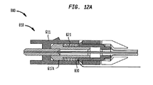
次に図12Aおよび12Bを参照すると、光学組立体800は、光学組立体800がセンサ630に加えて、または、図示する例におけるように、センサ630の代わりにセンサ830を有する第1のコネクタ組立体810を含むことができることを顕著に除いて、光学組立体600と実質的に同様でよい。センサ830は、弾性素子621上に配置することができる。センサ830は、弾性素子621の表面の2点間の距離の変化を検知するために弾性素子の表面に沿って配置することができるマイクロひずみゲージでよい。この構成において、ひずみゲージは、上にひずみゲージが位置する弾性素子の表面が伸縮するとき抵抗が変化する可変抵抗素子でよい。
Next, referring to FIGS. 12A and 12B, the
このようにして、ハウジング611内の内側フェルール部分617Aが後方移動しまたは引き込み次第、センサ830は、弾性素子621の表面上の圧縮、したがって移動を検知することができる。センサ830がそのように所定の許容差範囲内で弾性素子621の表面の2点間の距離の変化を検知するとき、センサ830は、ライトパネル(図示せず)などの遠隔電子デバイスに伝達することができる電気信号などであるが、それに限定されない信号を生成し、または電子デバイスに結合された遠隔信号受信機に経路指定するための信号を生成および送信することができ、または代替として、第2のコネクタ組立体640が所定の深さまでアダプタ650内に挿入されたとの指示を提供するために電気信号などであるが、それに限定されない信号を生成または送信することを停止することができる。
In this way, as soon as the
ひずみゲージを利用する構成において、ひずみゲージセンサは、弾性素子の表面上の変化が起きまたは起きることを停止するとき変化することができる抵抗、容量、またはインダクタンスなどの可変電気的特性を有することができる。そのような構成において、センサ内の抵抗、容量、またはインダクタンスの変化は、電気的特性の変化に対応する電気信号を受信する遠隔受信機によって認識し、線を介してなど、または信号伝達手段のようにひずみゲージセンサから伝達することができる。別の代替構成において、センサ830は、マイクロひずみゲージに対して今説明したものなどの信号を送信することによって弾性素子621の移動に反応することができる、弾性素子621上に、または弾性素子621に近接して配置された圧電材料(図示せず)でよい。
In configurations that utilize strain gauges, strain gauge sensors can have variable electrical properties such as resistance, capacitance, or inductance that can change when changes on the surface of the elastic element occur or stop occurring. it can. In such a configuration, changes in resistance, capacitance, or inductance in the sensor are recognized by a remote receiver that receives the electrical signal corresponding to the change in electrical characteristics, via a wire, etc., or in a signaling means. It can be transmitted from the strain gauge sensor. In another alternative configuration, the
図12Cに示すように図12Aおよび12Bの例に示す代替構成の別の代替構成において、光学組立体800Aおよびその第1のコネクタ組立体810Aは、第1のコネクタ組立体810Aの弾性素子621が、電流がコイルばねの対向する端部に取り付けた電線835Aと835Bとの間のばねを流れるとき誘導性素子として働くコイルばねでよいことを除いて、それぞれ、光学組立体800および第1のコネクタ組立体810と同じでよい。このようにして、弾性素子621の伸縮により、弾性素子の長さの変化、したがって弾性素子のインダクタンスの変化が生じ、それはインダクタンスの変化により弾性素子に生成された電流に対応する電気信号を受信する電子デバイスによって測定することができ、それにおいて、電気信号が線を介してなど、または信号伝達手段のように伝達される。図示するように、鉄またはニッケルで製作してよいが、それであることに限定されない、磁心831が、第1のコネクタ組立体810Aの内側フェルール部分617Aの溝部818の周りに延びることができる。このようにして、弾性素子621および磁心831によって生成された磁束、したがってインダクタンスは、弾性素子だけによって生成されたインダクタンスよりも実質的に増加させることができる。このようにして、弾性素子の長さの変化は、検知するのが容易であり、第2のコネクタ組立体640が所定の深さまでアダプタ650内に挿入されたとの指示はより信頼性がある。
As shown in FIG. 12C, in another alternative configuration of the alternative configuration shown in the examples of FIGS. 12A and 12B, the optical assembly 800A and its
図12Aおよび12Bの例に示す代替構成のさらに別の代替構成(図示せず)において、コンデンサを形成するために導電性金属板などであるがそれに限定されない電極を弾性素子621の端部に取り付けることができる。このようにして、弾性素子621の伸縮により、弾性素子の長さの変化、したがってコンデンサの容量の変化が生じ、それは容量の変化に対応する電気信号を受信する電子デバイスによって測定することができ、それにおいて、電気信号が、線を介してなど、または信号伝達手段のように伝達される。
In yet another alternative configuration (not shown) of the alternative configuration shown in the examples of FIGS. 12A and 12B, an electrode such as, but not limited to, a conductive metal plate is attached to the end of the
次に図13を参照すると、光学組立体900は、光学組立体900が弾性素子ストッパ623の代替構成を含むことができ、図示する例におけるように、場合によっては、センサ630を含まない可能性があることを顕著に除いて、光学組立体600と実質的に同様でよい。そのような構成において、コネクタ組立体910は、図示するように、後方ストッパ923Aの内径と同じ、または実質的に同じである外径をその後端部に有することができる前方ストッパ923を含むことができ、後方ストッパ923Aから、前方ストッパ923およびハウジング611が取外し可能であり得る。光学組立体900は、図示するようにバッファ管および撚糸組立体627、圧着リング628、ならびにブーツ629の組立体に圧着することができる後方ストッパ923Aに装着することができるセンサ930を含むことができる。このようにして、コネクタ組立体910は、コネクタ組立体が欠陥となったときなど、センサ930および後方ストッパ923Aを再使用しながら別のコネクタ組立体で置き換えることができる。
Next, referring to FIG. 13, in the
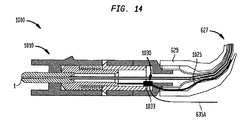
図14を参照すると、光学組立体1000は、光学組立体1000がセンサ930に加えて、またはその代わりにセンサ1030を有する第1のコネクタ組立体1010を含むことができることを顕著に除いて、光学組立体900と実質的に同様でよい。図13に示すようにセンサ930のセンサモジュール933から延びるケーブル635の代わりに、センサ1030は、ケーブル635Aならびにセンサモジュール1033から延びるケーブル1025を含むことができる。ケーブル635Aは、ライトパネル(図示せず)などの遠隔電子デバイスに伝達することができる、センサ1030によって生成され、または電子デバイスに結合された信号受信機に経路指定するためにセンサ1030によって生成および送信された、電気信号などであるがそれに限定されない信号を搬送することができ、または代替として、コネクタ組立体640などの第2のコネクタ組立体がアダプタ650などのアダプタ内に所定の深さまで挿入されたとの指示を提供するために、電気信号などであるがそれに限定されない信号を搬送することを停止することができる。
Referring to FIG. 14, the
ケーブル1025は、ケーブルが実質的に光ファイバ1と同じ経路に沿って通るように、ブーツとバッファ管および撚糸組立体627との間でブーツ629中を通って延びることができる。ケーブル1025は、その長さに沿って1つまたは複数のセンサ(図示せず)を含むことができ、センサは、当業者には周知のように、マイクロひずみゲージでよく、マイクロひずみゲージは、たいがいケーブルの屈曲または変形によって生じる、ケーブルの長さの変化またはより正確にはケーブルの表面の2点間の距離の変化を検知する。この構成において、センサは、上にセンサが位置するケーブルの表面が伸縮するとき抵抗が変化する可変抵抗素子でよい。図示する例において、センサ1030は、ケーブルの長さの変化が起きたとき、抵抗の変化に対応し、マイクロひずみゲージから伝達された電気信号を受信することができる。任意のそのようなケーブル1025の表面の変化が閾値に等しいか、または閾値を超えるとき、センサがライトパネル(図示せず)などの遠隔電子デバイスに伝達することができる電気信号などであるが、それに限定されない信号を生成し、または電子デバイスに結合された信号受信機に経路指定するための信号を生成および送信することができ、または代替として、ケーブル、したがって可能性のある光ファイバ1が、その一部分において不必要に屈曲されて、例えば、最小曲げ半径未満を有することを要員に警告するために、電気信号などであるが、それに限定されない信号を生成または送信することを停止することができるように、センサ1030を設定することができる。図14の例において、光ファイバがその長さに沿って最小曲げ半径を有することが所望されるとき、結果として最小曲げ半径未満を有するケーブルの一部分となる光ファイバ1の長さに沿った任意の変化をセンサ1030によって検知されると、一般に望ましくないとみなされ、警告信号が生成される。
The
図15を参照すると、光学組立体1100は、光学組立体1100の第1および第2のコネクタ組立体1110、640の外側フェルール部分617Bの係合によって生じた第1のコネクタ組立体1110の外側フェルール部分617Bの変位により、第2のコネクタ組立体640がアダプタ650内に挿入されたとの指示を提供するために、光学組立体1100がセンサ630に加えて、または、図示する例におけるように、その代わりに、電極1131、1132を有する第1のコネクタ組立体1110を含むことができることを顕著に除いて、光学組立体600と実質的に同様でよい。フェルール電極1131は、1つまたは複数の締結具、吸着可能磁気素子、またはエポキシでよいが、それであることに限定されない化学接着剤によってなどであるがそれに限定されないで、内側フェルール部分617Aの前端部に取り付けることができ、銅線でよいが、それであることに限定されないケーブル1135Aによって論理回路99に電気的に接続することができる。ハウジング電極1132は、1つまたは複数の締結具、吸着可能磁気素子、またはエポキシでよいが、それであることに限定されない化学接着剤によってなどで、ハウジング611の隔壁612の後ろ向き側に取り付けることができ、銅線でよいが、それであることに限定されないケーブル1135Bによって論理回路99に電気的に接続することができる。
Referring to FIG. 15, the optical assembly 1100 is the outer ferrule of the first connector assembly 1110 resulting from the engagement of the
このようにして、第2のコネクタ組立体640が、図15の上部におけるように、アダプタ650内に挿入されないとき、内側フェルール部分617Aの前端部は、ハウジング611の隔壁612に対してその最前方位置にあってよい。このようにして、フェルール電極1131およびハウジング電極1132は、閉回路が論理回路99、ケーブル1135A、フェルール電極1131、ハウジング電極1132、およびケーブル1135Bによって形成されるように、接触することができる。対照的に、図15の下部におけるように、第2のコネクタ組立体640がアダプタ650内に挿入されたとき、内側フェルール部分617Aの前端部は、ハウジング611の隔壁612から離れるように設定することができる。このようにして、フェルール電極1131およびハウジング電極1132は、論理回路99、ケーブル1135A、フェルール電極1131、ハウジング電極1132、およびケーブル1135Bによって形成された常時閉回路が開くように、接触しない可能性がある。そのような構成において、論理回路99は、回路を閉じたとき電源が切られる接続された電子工学または光電子工学システム、および回路を開いたとき電源が投入される接続された電子工学または光電子工学システムを制御することができる。このようにして、第1のコネクタ組立体1110を通る光放出を停止し、損傷を防止し、エネルギーを節約することができる。代替構成において、論理回路99などの論理回路は必要とされない可能性があり、ケーブル1135A、フェルール電極1131、ハウジング電極1132、およびケーブル1135Bは、フェルール電極1131とハウジング電極1132との間の接触に基づいて開閉することができる別の回路の一部を形成することができる。
In this way, when the
図16に示すように、光学組立体1200は、光学組立体1200が、光学組立体1200の第1および第2のコネクタ組立体1210、640の外側フェルール部分617Bの係合によって生じた第1のコネクタ組立体1210の外側フェルール部分617Bの変位により、第2のコネクタ組立体640が所定の深さまでアダプタ650内に挿入されたとの指示を提供するために、電極1131、1132に加えて、または、図示する例におけるように、それらの代わりに、電極1231、1232を有する第1のコネクタ組立体1210を含むことができることを顕著に除いて、光学組立体1100と実質的に同様でよい。ストッパ電極1231は、1つまたは複数の締結具、吸着可能磁気素子、またはエポキシでよいが、それであることに限定されない化学接着剤によってなどであるがそれに限定されないで、弾性ストッパ素子623の前向き内部段に取り付けることができる。ストッパ電極1231は、絶縁素子1237ならびに絶縁素子の両側に取り付けた導電性上側ベース1236Aおよび導電性下側ベース1236Bを含むことができる。絶縁素子1237は、プラスチックまたはゴム材料などであるがそれに限定されない、絶縁または誘電材料で製作してよい。このようにして、上側ベース1236Aと下側ベース1236Bとは、電気的に接続されない可能性がある。上側ベース1236Aは、ケーブル1235Aによって論理回路99に電気的に接続することができ、下側ベース1236Bは、ケーブル1235Bによって論理回路99に電気的に接続することができ、それにおいて、ケーブルのそれぞれは、銅線でよいがそれであることに限定されない。
As shown in FIG. 16, in the
さらに図示するように、上側ベース1236Aおよび下側ベース1236Bは、内側フェルール部分617Aに向かって前方方向に延びるそれぞれの上側および下側プロング1237A、1237Bに取り付けることができる。このようにして、上側および下側プロング1237A、1237Bにより、ストッパ電極1231は、図示する配列におけるように、フェルール電極1232を含む他の電極に接触する縦方向区間を有することが可能になる。
As further illustrated, the
フェルール電極1232は、1つまたは複数の締結具、吸着可能磁気素子、またはエポキシでよいが、それであることに限定されない化学接着剤によってなどであるがそれに限定されないで、内側フェルール部分617Aの後ろ向き側に取り付けることができる。図示するように、フェルール電極1232は、フェルール電極が内側フェルール部分617Aの後ろ向き側の全周囲に接触するように、円環の形であってよいが、それであることに限定されない。
The
図16の下部におけるように、第2のコネクタ組立体640がアダプタ650内に挿入されたとき、内側フェルール部分617Aの後端部に取り付けたフェルール電極1232は、弾性ストッパ素子623の前向き内部段に取り付けたストッパ電極1231の上側および下側プロング1237A、1237Bと接触して配置することができる。このようにして、閉回路が論理回路99、ケーブル1235A、ストッパ電極1231、フェルール電極1232、およびケーブル1235Bによって形成される。プロング1237A、1237Bの長さにより、電極1231、1232がストッパ電極1231と電気的に接触するために内側フェルール部分617Aが後方にずっと弾性ストッパ素子623の前向き内部段に隣接した上側および下側ベース1236A、1236Bまで移動、したがってそれらに接触するのは不要である。
As in the lower part of FIG. 16, when the
動作において、第2のコネクタ組立体640がアダプタ650内に完全に挿入されたとき、第1および第2のコネクタ組立体1210、640の外側フェルール部分617Bは、外側フェルール位置および内側フェルール部分617Aの長さおよび相対位置ならびに第1および第2のコネクタ組立体の弾性素子621によって供給される相対力により異なることがあるアダプタ650内の相対位置(破線699で表される)において接触することができる。したがって、図示する例におけるように、内側フェルール部分617A、したがってフェルール電極1232が、フェルール電極1232とストッパ電極1231との間の初期電気的結合の後でも、さらに後方に移動することができるように、上側および下側プロング1237A、1237Bは、内方に可撓であり得る。このようにして、第2のコネクタ組立体640の内側フェルール部分617A、外側フェルール部分617B、および弾性素子621は、部分ごとに異なるサイズにし、それでもアダプタ650内に第2のコネクタ組立体640を挿入し次第、ストッパ電極1231とフェルール電極1232との間の電気的結合を生じることができる。一例において、第2のコネクタ組立体640がアダプタ650内に挿入されたとき、論理回路99、ケーブル1235A、ストッパ電極1231、フェルール電極1232、およびケーブル1235Bによって形成された回路は、第1のコネクタ組立体1210の内側および外側フェルール部分617A、617Bが最小0.25mmだけ後方に移動する限り閉じることができる。
In operation, when the
さらに、上側および下側プロング1237A、1237Bは、論理回路99、ケーブル1235A、ストッパ電極1231、フェルール電極1232、およびケーブル1235Bによって形成された回路が閉じたままになっている間、内側および外側フェルール部分617A、617Bが0.25mmよりも長い距離、例えば、1.0mm以上後方に移動することができるように、ばね作用を与えるためにベース1236A、1236Bに対して一端が飛び出すことができる。上側および下側プロング1237A、1237Bに加えて、またはそれらの代替として、第2のコネクタ組立体の内側および外側フェルール部分の後方移動の様々な距離においてストッパ電極とフェルール電極との間で維持される導電性結合をもたらすために、以下に図17で説明する例においてなど、コイルまたは板ばねをフェルール電極1232に取り付けることができ、またはコイルまたは板ばねはフェルール電極1232でよい。
Further, the upper and
対照的に、図16の上部と同様に第2のコネクタ組立体640がアダプタ650内に挿入されないとき、内側フェルール部分617Aの後端部に取り付けたフェルール電極1232は、ストッパ電極1231から最も離れたその最前方位置にあることができる。このようにして、ストッパ電極1231とフェルール電極1232とは、論理回路99、ケーブル1235A、ストッパ電極1231、フェルール電極1232、およびケーブル1235Bによって形成された常時閉回路が開いているように、接触しない可能性がある。そのような構成において、論理回路99は、回路を閉じたとき電源が投入される接続された電子工学または光電子工学システム、および回路を開いたとき電源が切られる接続された電子工学または光電子工学システムを制御することができる。このようにして、第1のコネクタ組立体1210を通る光放出を停止し、損傷を防止し、エネルギーを節約することができる。代替構成において、論理回路99などの論理回路は必要とされない可能性があり、ケーブル1235A、ストッパ電極1231、フェルール電極1232、およびケーブル1235Bは、ストッパ電極1231とフェルール電極1232との間の接触に基づいて開閉することができる別の回路の一部を形成することができる。
In contrast, the
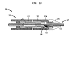
次に図17を参照すると、光学組立体1300は、光学組立体1300が第2のコネクタ組立体640が所定の深さまでアダプタ650内に挿入されたとの指示を提供するために電極1231、1232の代わりに電極1331、1332を有する第1のコネクタ組立体1310を含むことができることを顕著に除いて、光学組立体1200と実質的に同様でよい。ストッパ電極1331は、ストッパ電極1231と同じように弾性ストッパ素子623の前向き内部段に取り付けることができる。図示するように、ストッパ電極1331は、ストッパ電極が弾性ストッパ素子623の前向き内部段の全周囲に接触するように円環の形であってよいが、それであることに限定されない。
Next, referring to FIG. 17, the
ストッパ電極1331は、絶縁素子1337ならびに絶縁素子の両側に取り付けた上側ベース1336Aおよび下側ベース1336Bを含むことができる。絶縁素子1337は、ストッパ電極1231の絶縁素子1237と同じで、または酷似していてよい。このようにして、上側ベース1336Aおよび下側ベース1336Bは、互いに電気的に接続されない可能性がある。上側ベース1336Aは、ケーブル1235Aによって論理回路99に電気的に接続することができ、下側ベース1336Bは、ケーブル1235Bによって論理回路99に電気的に接続することができる。
The
フェルール電極1332はコイルばねの形であってよい。フェルール電極1332は、1つまたは複数の締結具、吸着可能磁気素子、またはエポキシでよいが、それであることに限定されない化学接着剤によってなどであるがそれに限定されないで、内側フェルール部分617Aの後ろ向き側に取り付けることができる。図示するように、フェルール電極1332は、フェルール電極の前端部が実質的に内側フェルール部分617Aの後ろ向き側の全周囲に接触するように実質的に円環の形であってよいが、それであることに限定されない。フェルール電極1332の後端部1333は、第2のコネクタ組立体640が所定の深さまでアダプタ650内に挿入されたとき、後端部がストッパ電極1331の上側ベース1336Aおよび下側ベース1336Bの両方に同時に接触することができるように、実質的に平坦でよい。
The
このようにして、閉回路が、前に本明細書に説明した論理回路99などの論理回路、ケーブル1235A、ストッパ電極1331、フェルール電極1332、およびケーブル1235Bによって形成される。フェルール電極1332の圧縮性により、フェルール電極は、第2のコネクタ組立体1310の内側および外側フェルール部分617A、617Bの後方移動の様々な距離においてストッパ電極1331とフェルール電極1332との間に維持される導電性結合をもたらすことができる。
In this way, the closed circuit is formed by logic circuits such as the
対照的に、第2のコネクタ組立体640がアダプタ650内に挿入されないとき、フェルール電極1332は、ストッパ電極1331から最も離れたその最前方位置にあってよい。このようにして、ストッパ電極1331とフェルール電極1332とは、論理回路、ケーブル1235A、ストッパ電極1331、フェルール電極1332、およびケーブル1235Bによって形成された常時閉回路が開いているように、接触しない可能性がある。そのような構成において、論理回路は、回路を閉じたとき電源が投入される接続された電子工学または光電子工学システム、および回路を開いたとき電源が切られる接続された電子工学または光電子工学システムを制御することができる。代替構成において、論理回路は必要とされない可能性があり、ケーブル1235A、ストッパ電極1331、フェルール電極1332、およびケーブル1235Bは、ストッパ電極1331とフェルール電極1332との間の接触に基づいて開閉することができる別の回路の一部を形成することができる。
In contrast, when the
図18を参照すると、光学組立体1400は、光学組立体1400が第2のコネクタ組立体640が所定の深さまでアダプタ650内に挿入されたとの指示を提供するために電極1331、1332の代わりに電極1431、1432を有する第1のコネクタ組立体1410を含むことができることを顕著に除いて、光学組立体1300と実質的に同様でよい。さらに、光学組立体1400は、内側フェルール組立体617A、弾性素子621、および弾性ストッパ素子623の代わりに内側フェルール組立体1417A、弾性素子1421、および弾性ストッパ素子1423を含むことができる。
Referring to FIG. 18, the
内側フェルール組立体1417Aは、内側フェルール組立体1417Aの後端部によって画定された溝部1419の周りに延びることができる管1418を含むことができる。管1418は、プラスチックなどの絶縁材料で製作してよい。第1のコネクタ組立体610の弾性素子621と異なり、弾性素子1421は、依然として弾性ストッパ素子1423の前端部と当接しながら内側フェルール組立体1417Aの後端部を超えて延びることができる。弾性ストッパ素子1423は、弾性素子1421がストッパ内腔1425内に延びないように第1のコネクタ組立体610のストッパ素子623よりも狭いストッパ内腔1425を有することができる。
The
このようにして、ストッパ電極1431を弾性ストッパ素子1423の前端部に取り付けることができる。図示するように、ストッパ電極1431は、ストッパ電極が弾性ストッパ素子1423の前端部の全周囲に接触するように円環の形であってよいが、それであることに限定されない。
In this way, the
ストッパ電極1431は、絶縁素子1437ならびに絶縁素子の両側に取り付けた導電性上側ベース1436Aおよび導電性下側ベース1436Bを含むことができる。このようにして、上側ベース1436Aと下側ベース1436Bとは、互いに電気的に接続されない可能性がある。上側ベース1436Aは、ケーブル1235Aによって論理回路99に電気的に接続することができ、下側ベース1436Bは、ケーブル1235Bによって論理回路99に電気的に接続することができる。
The
フェルール電極1432は、コイルばねの形であってよい。フェルール電極1432は、溝部1419に沿って形成された内側フェルール部分617Aの後ろ向き段に、1つまたは複数の締結具、吸着可能磁気素子、またはエポキシでよいが、それであることに限定されない化学接着剤によってなどであるがそれに限定されないで、取り付けることができ、内側フェルール部分の後端部の周りに延びることができる。したがって、フェルール電極1432は、フェルール電極を弾性素子1421から分離することができる管1418内に位置決めすることができる。
The
図示するように、フェルール電極1432は、フェルール電極の前端部が実質的に内側フェルール部分1417Aの後ろ向き段の全周囲に接触するように、実質的に円環の形であってよいが、それであることに限定されない。フェルール電極1432の後端部1433は、第2のコネクタ組立体640が所定の深さまでアダプタ650内に挿入されたとき、後端部がストッパ電極1431の上側ベース1436Aおよび下側ベース1436Bの両方に同時に接触することができるように、実質的に平坦でよい。
As shown, the
このようにして、閉回路が、前に本明細書に説明した論理回路99などの論理回路、ケーブル1235A,ストッパ電極1431、フェルール電極1432、およびケーブル1235Bによって形成される。フェルール電極1432の圧縮性により、フェルール電極は、第2のコネクタ組立体1410の内側および外側フェルール部分1417A、617Bの後方移動の様々な距離においてストッパ電極1431とフェルール電極1432との間に維持される導電性結合をもたらすことができる。対照的に、第2のコネクタ組立体640がアダプタ650内に挿入されないとき、フェルール電極1432は、ストッパ電極1431から最も離れたその最前方位置にあってよい。このようにして、ストッパ電極1431とフェルール電極1432とは、論理回路、ケーブル1235A、ストッパ電極1431、フェルール電極1432、およびケーブル1235Bによって形成された常時閉回路が開いているように、接触しない可能性がある。そのような構成において、論理回路は、回路を閉じたとき電源が投入される接続された電子工学または光電子工学システム、および回路を開いたとき電源が切られる接続された電子工学または光電子工学システムを制御することができる。代替構成において、論理回路は必要とされない可能性があり、ケーブル1235A、ストッパ電極1431、フェルール電極1432、およびケーブル1235Bは、ストッパ電極1431とフェルール電極1432との間の接触に基づいて開閉することができる別の回路の一部を形成することができる。
In this way, the closed circuit is formed by logic circuits such as the
図19を参照すると、光学組立体1500は、光学組立体1500が、光学組立体の第1および第2のコネクタ組立体の外側フェルール部分617Bの係合によって生じた第1のコネクタ組立体の外側フェルール部分617Bの変位により第2のコネクタ組立体640がアダプタ650内に挿入されたとの指示を提供するために、センサ630に加えて、または、図示する例におけるように、その代わりに、センサ1530を有する第1のコネクタ組立体1510を含むことができることを顕著に除いて、光学組立体600と実質的に同様でよい。センサ1530は、1つまたは複数の締結具、吸着可能磁気素子、またはエポキシなどであるがそれに限定されない化学接着剤によってなどであるがそれに限定されないで、ハウジング611の突起611Aの後方側に取り付けることができ、銅線でよいが、それであることに限定されないケーブル1535によって論理回路99などの論理回路に電気的に接続することができる。突起611Aは、アダプタ650の刻み目651内に延び、嵌合するために、図示するように三角柱の形などの構成にすることができる。このようにして、コネクタ組立体1510は、突起611Aの後方側がコネクタ組立体のアダプタからの引き抜けに抵抗するために、刻み目651の前向き側に寄り掛かることができるようにアダプタ650に取り付けることができる。
Referring to FIG. 19, the
センサ1530は、センサ1530が圧力センサまたは変位センサでよいが、それであることに限定されない点において、センサ630と同じまたは実質的に同様でよい。圧力センサとして、センサ1530は、撓み可能ダイアフラムまたは他の周知の力感知手段を含むことができる。センサ630と同じように、センサ1530は、センサの静止位置のセンサのセンサモジュールから延長可能であり得、プローブが静止位置から引っ込んだ位置に引っ込むように、引き込み可能であり得るプローブ(図示せず)を含むことができ、それにおいて、静止位置のセンサモジュールにおいて受けていないプローブの少なくとも一部分をセンサモジュールにおいて受ける。静止位置において、センサ(および、プローブを有するセンサの場合、センサのプローブ)は、アダプタ650の刻み目651の前向き側に接触し、またはアダプタ650の刻み目651の前向き側から離間することができる。他の構成において、この場合もセンサ630と同じように、マイクロひずみゲージは、プローブの延長および引き込みの間、ひずみゲージが弾性素子の表面の変形を検知することができるように、プローブを有するセンサのプローブに取り付けた弾性素子に付着させることができ、センサのセンサモジュール内にあり得る。
The
図19の上部と同様に第2のコネクタ組立体640がアダプタ650内に挿入されないとき、光学組立体600の構成と同様に、内側フェルール部分617Aの前端部は、ハウジング611の隔壁612に対してその最前方位置にあってよい。ファイバおよびフェルール組立体616が静止位置にあるように、第2のコネクタ組立体640が光学組立体1500のアダプタ650内に完全に挿入されたとき、第1および第2のコネクタ組立体1510、640の外側フェルール部分617Bの前端部は、それらの対向するファイバおよびフェルール組立体616が接触したままであるが、互いから離れる後部方向に向かう傾向があるように、互いに押すことができる。したがって、第1のコネクタ組立体610のファイバおよびフェルール組立体616の後端部は、ハウジング611がストッパ623の前方フランジ624によって後方に押されるように、後方に押される可能性がある。このようにして、センサ1530(および、プローブを有するセンサの場合、センサのプローブ)は、アダプタ650の刻み目651の前向き側に対して押圧することができる。センサ1530が所定の許容差範囲内の力によってそのように押圧されたとき、センサ1530は、第2のコネクタ組立体が所定の深さまでアダプタ650内に挿入されるように、第2のコネクタ組立体640が第1のコネクタ組立体1510に対して十分な力を印加したとの指示を提供する信号をケーブル1535に沿って生成し、または生成することを停止するためにセンサ630の構成のいずれかと同じように動作することができる。第2のコネクタ組立体640が所定の深さにないとき、第1のコネクタ組立体1510を通る光放出を停止し、損傷を防止し、エネルギーを節約することができる。
When the
光学組立体1500の代替構成において、センサ1530は、第1のコネクタ組立体1510の突起611Aの後方側の代わりに第2のコネクタ組立体のハウジングの突起の後方側に取り付けることができる。このようにして、センサ1530は、第2のコネクタ組立体が所定の深さまでアダプタ650内に挿入されるように、第2のコネクタ組立体が第1のコネクタ組立体1510に対して十分な力を印加したとの指示を提供する信号をケーブル1535に沿って生成し、または生成することを停止するためにセンサ630の構成のいずれかと同じように動作することができる。
In an alternative configuration of the
図20に示すように、光学組立体1600は、光学組立体1600が、光学組立体の第1および第2のコネクタ組立体の外側フェルール部分617Bの係合によって生じた第1のコネクタ組立体の外側フェルール部分617Bの変位により、第2のコネクタ組立体640がアダプタ650内に挿入されたとの指示を提供するために、センサ1530なしで第1のコネクタ組立体1610を含み、光学組立体のアダプタ650に取り付けたセンサ1630をさらに含むことができることを顕著に除いて、光学組立体1500と実質的に同様でよい。センサ1630は、センサ1530と同じまたは実質的に同様でよい。センサ1630は、センサの力感知手段がハウジング611の突起611Aの後方側の方を向くように、1つまたは複数の締結具、吸着可能磁気素子、またはエポキシなどであるがそれに限定されない化学接着剤によってなどであるがそれに限定されないで、アダプタ650の刻み目651の前向き側に取り付けることができる。このようにして、静止位置において、センサ1630は、突起611Aの後方側と接触し、または突起611Aの後方側から離間することができる。
As shown in FIG. 20, the
ハウジング611が光学組立体1600のアダプタ650内への第2のコネクタ組立体640の挿入により後方に押されたとき、突起611Aの後方側は、センサ1630に対して押圧することができる。センサ1630は、銅線でよいが、それであることに限定されないケーブル1635によって論理回路99などの論理回路に電気的に接続することができる。このようにして、センサ1630が所定の許容差範囲内の力によって押圧されたとき、第2のコネクタ組立体が所定の深さまでアダプタ650内に挿入されるように、第2のコネクタ組立体640が第1のコネクタ組立体1610に対して十分な力を印加したとの指示を提供する信号をケーブル1635に沿って生成し、または生成することを停止するために、センサ630、1530のいずれかの構成のいずれかと同じように動作することができる。第2のコネクタ組立体640が所定の深さにないとき、第1のコネクタ組立体1610を通る光放出を停止し、損傷を防止し、エネルギーを節約することができる。
When the
光学組立体1600の代替構成において、センサ1630は、第1のコネクタ組立体1610を受けるアダプタ650の刻み目651の前向き側の代わりに第2のコネクタ組立体640を受けるアダプタの一側面上の刻み目の前向き側に取り付けることができる。このようにして、センサ1630は、第2のコネクタ組立体がアダプタ内に所定の深さまで挿入されるように、第2のコネクタ組立体640が第1のコネクタ組立体1610に対して十分な力を印加したとの指示を提供する信号をケーブル1635に沿って生成し、または生成することを停止するためにセンサ630の構成のいずれかと同じように動作することができる。
In an alternative configuration of the
センサがセンサモジュールから延長可能なプローブを有する光学組立体1600の別の代替構成において、センサモジュールは、アダプタの端部上などであるがそれに限定されない、アダプタ650(図示せず)の外側に取り付けることができ、それにおいて、プローブは、アダプタを貫通して形成された穴部を通って延長可能である。このようにして、センサのプローブは、センサが、プローブを有するセンサ630、1530、1630の構成のいずれかと同じように動作するように、ハウジング611の突起611Aによって押圧することができる。
In another alternative configuration of the
図21、21A、および21Bを参照すると、光学組立体1700が、アダプタ1750ならびに第1のLCコネクタ組立体1710および第2のLCコネクタ組立体1740を含むことができ、それらは、それらのアダプタ内への挿入および光学組立体1500の第1および第2のコネクタ組立体1510、640が互いに当接することができるのと実質的に同じように互いへの当接により互いに係合可能であり得る。アダプタ1750は、主開口1752および主開口の最上部から延びるスロット1754を画定することができ、スロットを貫通して延び、アダプタの最上部から主開口と交差する穴部1756をさらに画定することができる。第1および第2のLCコネクタ組立体1710、1740の両方は、ハウジング1711と、ハウジングから延びるレバー1711Aとを含むことができる。図示するように、レバー1711Aは、ハウジングを破壊することなくレバーがハウジングから分離不能であるように、ハウジング1711に統合することができる。レバー1711Aは、第1の軸部1712と第2の軸部1713とを含むことができ、それにおいて、第1の軸部が第2の軸部をレバーの台に取り付ける。第1の軸部1712は、第2の軸部1713よりも広くすることができる。このようにして、第1および第2の軸部1712、1713は、アダプタ1750の主開口1752内で摺動し、または他の方法で移動することができるが、軸部1713だけがスロット1754内で摺動し、または他の方法で移動することができる。
With reference to FIGS. 21, 21A, and 21B, the
第1のLCコネクタ組立体1710は、第2のLCコネクタ組立体1740がアダプタ1750内に完全に挿入されたとの指示を提供するために、センサ1530と同じまたは実質的に同様でよいセンサ1730を含むことができる。センサ1730は、センサのプローブがアダプタ1750の穴部1756の後方部分の方に向くように、レバー1711Aの第1および第2の軸部1712、1713の交差によって画定された段1714に、1つまたは複数の締結具、吸着可能磁気素子、またはエポキシなどであるがそれに限定されない化学接着剤によってなどであるがそれに限定されないで、取り付けることができる。このようにして、静止位置において、センサ1730は、穴部1756の後方部分に接触し、または穴部1756の後方部分から離間することができる。
The first
ハウジング1711が、光学組立体1700のアダプタ1750内への第2のLCコネクタ組立体1740の挿入により後方に押されたとき、センサ1730は、穴部1756の後方部分に対して押圧することができる。センサ1730は、銅線でよいが、それであることに限定されないケーブル1735によって論理回路99などの論理回路に電気的に接続することができる。このようにして、センサ1730が所定の許容差範囲内の力によって押圧されたとき、第2のコネクタ組立体がアダプタ1750内に所定の深さまで挿入されるように、第2のLCコネクタ組立体1740が第1のコネクタ組立体1710に対して十分な力を印加したとの指示を提供する信号をケーブル1735に沿って生成し、または生成することを停止するために、センサ1730は、センサ630、1530、1630の構成のいずれかと同じように動作することができる。第2のLCコネクタ組立体1740が所定の深さにないとき、第1のLCコネクタ組立体1710を通る光放出を停止し、損傷を防止し、エネルギーを節約することができる。
When the
図22および22Aを参照すると、光学組立体1800は、光学組立体1800が、第2のLCコネクタ組立体1740がアダプタ1850内に挿入されたとの指示を提供するために、センサ1730なしで第1のLCコネクタ組立体1810を含むことができ、光学組立体のアダプタ1850に取り付けたセンサ1830をさらに含むことができることを顕著に除いて、光学組立体1700と実質的に同様でよい。アダプタ1850は、図22に最もよく示すように、アダプタ1750の穴部1756と実質的に同じである穴部1856から後部方向に、および図22Aに最もよく示すように、スロット1854から横方向に延びる刻み目1851をアダプタが画定することができることを除いて、アダプタ1750と実質的に同じでよい。センサ1830は、センサ1730と同じまたは実質的に同様でよい。センサ1830は、センサの力感知手段がアダプタの穴部1856に、またはアダプタの穴部1856内にあり、前方方向に向くように、1つまたは複数の締結具、吸着可能磁気素子、またはエポキシなどであるがそれに限定されない化学接着剤によってなどであるがそれに限定されないで、アダプタ1850に、アダプタの刻み目1851内においておよびアダプタの刻み目1851に対して取り付けることができる。このようにして、静止位置において、センサ1830は、レバー1711Aの第1および第2の軸部1712、1713の交差によって画定された段1714に接触し、または段1714から離間することができる。
With reference to FIGS. 22 and 22A, the
ハウジング1711が光学組立体1800のアダプタ1850内への第2のLCコネクタ組立体1740の挿入により後方に押されたとき、段1714をセンサ1830に対して押圧することができる。センサ1830は、銅線でよいが、それであることに限定されないケーブル1835によって論理回路99などの論理回路に電気的に接続することができる。このようにして、センサ1830は、センサ1830が所定の許容差範囲内の力によって押圧されたとき、第2のコネクタ組立体がアダプタ1850内に所定の深さまで挿入されるように、第2のLCコネクタ組立体1740が第1のコネクタ組立体1810に対して十分な力を印加したとの指示を提供する信号をケーブル1835に沿って生成し、または生成することを停止するために、センサ630、1530、1630、1730のいずれかの構成のいずれかと同じように動作することができる。第2のLCコネクタ組立体1740が所定の深さにないとき、第1のLCコネクタ組立体1810を通る光放出を停止し、損傷を防止し、エネルギーを節約することができる。
When the
図23を参照すると、光学組立体1900は、光学組立体1900がハウジング1711の代わりに本体1911およびレバー1911Aならびに本体1911とレバー1911Aの前端部1912Aとの間に取り付けたセンサ1930を有する第1のLCコネクタ組立体1910を含むことができることを顕著に除いて、光学組立体1700と実質的に同様でよい。図示するように、レバー1911Aは、本体に対して蝶番ピン1915を中心としてレバーが回転することが可能になるように蝶番ピン1915によって本体1911に取り付けることができる。
Referring to FIG. 23, the
第1のLCコネクタ組立体1910の本体1911が光学組立体1900のアダプタ1750内への第2のLCコネクタ組立体1740の挿入により後方に押されたとき、蝶番ピンを中心としてトルクを生み出すために穴部1756の後方部分によってレバー1911Aの段1914に対して印加された力により、前端部1912Aがセンサ1930に対して押圧することができるように、センサ1930は、蝶番ピン1915の前方にあることができる。センサ1930は、銅線でよいが、それであることに限定されないケーブル1935によって論理回路99などの論理回路に電気的に接続することができる。このようにして、センサ1930が所定の許容差範囲内の力によって押圧されたとき、センサ1930は、第2のコネクタ組立体がアダプタ1750内に所定の深さまで挿入されるように、第2のLCコネクタ組立体1740が第1のコネクタ組立体1910に対して十分な力を印加したとの指示を提供する信号をケーブル1935に沿って生成し、または生成することを停止するために、センサ630、1530、1630、1730、1830のいずれかの構成のいずれかと同じように動作することができる。第2のLCコネクタ組立体1740が所定の深さにないとき、第1のLCコネクタ組立体1910を通る光放出を停止し、損傷を防止し、エネルギーを節約することができる。
To generate torque around the hinge pin when the
図24を参照すると、光学組立体2000は、本体2011およびレバー2011Aのいずれかを破壊することなくレバーが本体から分離不能であるように、レバー2011Aを第1のLCコネクタ組立体2010の本体2011に統合することができることを顕著に除いて、光学組立体1900と実質的に同様でよい。光学組立体1900の動作と実質的に同様のやり方で、第1のLCコネクタ組立体2010の本体2011が光学組立体2000のアダプタ1750内への第2のLCコネクタ組立体1740の挿入により後方に押されたとき、レバー2011Aと本体2011との接合部分の周りでレバー2011Aの段2014に対して穴部1756の後方部分によって印加された力により、レバー2011Aの前端部2012Aをセンサ1930に対して押圧することができる。
Referring to FIG. 24, the
図25を参照し、本明細書に開示する検知システムは、スイッチもしくはセンサの作動によるか、または2つの電極間などの導電性接触によるかどうかにかかわらず、コネクタインターフェース、例えば、コネクタ組立体2103を有する印刷回路基板2102を含むラインカード2101などのネットワークまたはサーバ機器とともに利用することができる。この例において、ラインカード2101は、コネクタ組立体内に挿入された対応する外部コネクタの存在を検知することができるスイッチ、センサ、またはコネクタ組立体2103上の導電性接点のうちのいずれかを含むことができる。このようにして、コネクタ組立体2103は、外部コネクタがコネクタ組立体内に挿入されないとき、光を放出することを停止し、または代替構成において、光を能動的に放出することができる。
The detection system disclosed herein with reference to FIG. 25, whether by actuation of a switch or sensor or by conductive contact, such as between two electrodes, is a connector interface, eg, a
本明細書に開示した技術は、データに対応する光信号を伝達するそれぞれの光ファイバ、またはデータに対応する電気信号を伝達する導電性素子を保持するための光または電気信号伝達コネクタを含むがそれに限定されないいくつかの種類のエネルギー伝達コネクタに採用することができることを理解されたい。光信号伝達コネクタは、LC、SC、MPO、MTP、FC、ST、およびMUコネクタでよいがそれらであることに限定されない。一般的な例として、本技術は、前に本明細書に説明した外側および内側フェルール部分などのファイバフェルールおよびフェルールホルダ、前に本明細書に説明した弾性素子などのばねまたは他の弾性素子、前に本明細書に説明したハウジングなどのハウジング、ならびに前に本明細書に説明した弾性ストッパ素子などのばねストッパを含むコネクタに対して使用することができる。 Although the techniques disclosed herein include each optical fiber that transmits an optical signal corresponding to data, or an optical or electrical signal transfer connector for holding a conductive element that transmits an electrical signal corresponding to the data. It should be understood that it can be used in several types of energy transfer connectors, not limited to it. Optical signal transfer connectors may be, but are not limited to, LC, SC, MPO, MTP, FC, ST, and MU connectors. As a general example, the present technology includes fiber ferrules and ferrule holders such as the outer and inner ferrule portions previously described herein, springs or other elastic elements such as elastic elements previously described herein. It can be used for housings such as housings previously described herein, as well as connectors that include spring stoppers such as elastic stopper elements previously described herein.
本明細書に記載した開示は、具体的に本明細書に開示したかどうかにかかわらず、上記の特定の特徴の任意の可能な組合せを含むことをさらに理解されたい。例えば、特定の特徴が特定の態様、配列、構成、または実施形態の文脈で開示される場合、本技術の他の特定の態様、配列、構成、および実施形態との組合せで、および/またはそれらの文脈で、ならびに一般に本技術において、その特徴を可能な限り使用することもできる。 It is further appreciated that the disclosures described herein include any possible combination of the particular features described above, whether or not specifically disclosed herein. For example, where a particular feature is disclosed in the context of a particular embodiment, sequence, configuration, or embodiment, in combination with other particular embodiments, sequences, configurations, and embodiments of the present technology and / or them. The features may also be used wherever possible in the context of, and in general in the art.
さらに、本明細書における本技術を特定の特徴を参照して説明してきたが、これらの特徴は、単に本技術の原理および適用例を例示するに過ぎないことを理解されたい。したがって、本明細書に説明した様々な特徴のサイズの変更を含む数多くの変更を例示的な実施形態に加えることができること、および本技術の精神および範囲から逸脱することなく他の配列を考案することができることを理解されたい。この点において、本技術は、以下の段落に記載する具体的な特徴に加えて、数多くの追加の特徴を包含する。さらに、上述の開示は、本技術が以下に記載する特許請求の範囲によって定義されるとき、限定によるのではなく、例示によるものと解釈すべきである。
なお、本願における審査請求時の特許請求の範囲は、以下の通りである。
[請求項1]
内腔を有するハウジングと、
前記ハウジングの前記内腔内で平行移動可能なフェルールと、
前記ハウジングの前記内腔内に装着され、前記フェルールの平行移動を検知するように構成されたセンサであって、前記センサの電気的特性が、所定の位置への前記フェルールの平行移動を示すように変化する、センサとを備える、コネクタ組立体。
[請求項2]
前記センサは、前記プローブが前記フェルールとの接触の間、前記フェルールとともに平行移動するように、前記フェルールの平行移動の間、前記フェルールに接触するように構成されたプローブを含み、
前記センサの前記電気的特性は、前記プローブの前記平行移動に応じて前記フェルールが前記所定の位置まで平行移動したことを示すように変化する、請求項1に記載のコネクタ組立体。
[請求項3]
前記センサは、圧力または変位センサである、請求項1または請求項2に記載のコネクタ組立体。
[請求項4]
前記フェルールに当接した弾性素子をさらに備え、前記センサが、前記フェルールの平行移動の間、前記弾性素子の長さの変化を検知する、請求項1に記載のコネクタ組立体。
[請求項5]
前記フェルール中を通過する一部分を有する光ファイバをさらに備え、前記フェルールが、通過する前記光ファイバの前記一部分の位置を維持する、請求項1ないし請求項4のいずれか一項に記載のコネクタ組立体。
[請求項6]
ケーブルの長さに沿って位置決めされた第2のセンサを含む前記ケーブルをさらに備え、前記第2のセンサの電気的特性が、上に前記第2のセンサが位置する前記ケーブルの表面が変形したとき変化する、請求項1ないし請求項5のいずれか一項に記載のコネクタ組立体。
[請求項7]
警告信号が、前記第2のセンサの電気的特性の変化に対応する電気信号が遠隔電子デバイスに伝導され、少なくとも最小値を有するとき、前記遠隔電子デバイスによって生成される、請求項6に記載のコネクタ組立体。
[請求項8]
前記センサが、
前記ハウジングに装着された第1の導電性接点と、
前記フェルールに装着された第2の導電性接点とを備え、
前記フェルールが平行移動の第1の位置にあるとき、前記第2の導電性接点が、前記第1の接点と導電結合され、前記フェルールが平行移動の第2の位置にあるとき、前記第2の導電性接点が前記第1の接点と導電結合されない、請求項1に記載のコネクタ組立体。
[請求項9]
制御信号を周辺構成要素に提供するように構成された回路と、
請求項8に記載のコネクタ組立体であって、前記第1の接点と前記第2の接点とが導電結合されたとき、前記回路が前記制御信号を前記周辺構成要素に提供することを停止するように、前記第2の接点が、前記フェルールの端部上に装着される、コネクタ組立体とを備える、システム。
[請求項10]
制御信号を周辺構成要素に提供するように構成された回路と、
請求項8に記載のコネクタ組立体であって、前記第1の接点と第2の接点とが導電結合されたとき、前記回路が前記制御信号を前記周辺構成要素に提供するように、前記第2の接点が、前記フェルールの端部上に装着される、コネクタ組立体とを備える、システム。
[請求項11]
アダプタと、
前記アダプタによって受け、内腔を有するハウジングと、
前記ハウジングの前記内腔内で平行移動可能なフェルールと、
前記ハウジング上または前記アダプタ上に装着されたセンサであって、前記フェルールの平行移動を検知するように構成され、センサの電気的特性が、前記フェルールの所定の位置までの平行移動を示すように変化する、センサとを備える、コネクタ組立体。
[請求項12]
(i)前記センサを前記ハウジング上に装着したとき前記アダプタに対して、または(ii)前記センサを前記アダプタ上に装着したとき前記ハウジングとともにプローブが平行移動するように、前記センサが、(i)前記センサを前記ハウジング上に装着したとき前記アダプタに、または(ii)前記センサを前記アダプタ上に装着したとき前記ハウジングに接触するように構成された前記プローブを含み、前記センサの前記電気的特性が、前記プローブの平行移動に応じて前記フェルールが前記所定の位置まで平行移動したことを示すように変化する、請求項11に記載のコネクタ組立体。
[請求項13]
前記センサが、変位センサまたは圧力センサである、請求項11または請求項12に記載のコネクタ組立体。
[請求項14]
前記ハウジングから延びる突起をさらに備え、(i)前記センサを前記ハウジング上に装着するとき前記センサが前記突起上に装着され、または(ii)前記センサを前記アダプタ上に装着するとき前記プローブが前記突起に接触するように構成される、請求項11に記載のコネクタ組立体。
[請求項15]
前記ハウジングが、本体と前記本体から延びる突起とを含み、前記センサが、前記本体と前記本体および前記突起のいずれかの上の前記突起との間に装着され、(a)前記センサを前記本体上に装着したとき前記突起とともに、または(b)前記センサを前記突起上に装着したとき前記本体に対して、前記プローブが平行移動するように、前記センサが、(i)前記センサを本体上に装着するとき前記突起、または(ii)前記センサを前記突起上に装着するとき前記本体に接触するように構成されたプローブを含み、前記センサの前記電気的特性が、前記プローブの前記平行移動に応じて前記フェルールが前記所定の位置まで平行移動したことを示すように変化する、11に記載のコネクタ組立体。
[請求項16]
前記ハウジングから延びる突起をさらに備え、(i)前記センサを前記ハウジング上に装着するとき前記センサが前記突起上に装着され、または(ii)前記センサを前記アダプタ上に装着するとき前記センサが前記突起に接触するように構成され、前記フェルールの最小距離の平行移動の間、(i)前記センサを前記ハウジング上に装着したとき前記センサが前記アダプタからの力によって押圧され、または(ii)前記センサを前記アダプタ上に装着したとき前記突起が前記センサに対して力によって押圧され、前記センサの前記電気的特性が、前記センサに作用する前記力に応じて前記所定の位置まで前記フェルールが平行移動したことを示すように変化する、請求項11に記載のコネクタ組立体。
[請求項17]
前記ハウジングが、本体と前記本体から延びる突起とを含み、前記センサが、前記本体と前記本体および前記突起のいずれかの上の前記突起との間に装着され、(i)前記センサを前記突起上に装着するとき前記センサが前記本体に接触するように構成され、または(ii)前記センサを前記本体上に装着するとき前記センサが前記突起に接触するように構成され、前記フェルールの最小距離の平行移動の間、(i)前記センサを前記突起上に装着したとき前記センサが前記本体に対して力によって押圧され、または(ii)前記センサを前記本体上に装着したとき前記突起が前記センサに対して力によって押圧され、前記センサの前記電気的特性が、前記センサに作用する前記力に応じて前記フェルールが前記所定の位置まで平行移動したことを示すように変化する、請求項11に記載のコネクタ組立体。
[請求項18]
前記突起が、前記センサが前記本体上にあるとき、前記本体に蝶番式に接続される、請求項15または請求項17に記載のコネクタ組立体。
[請求項19]
前記突起が前記本体と一体である、請求項15または請求項17に記載のコネクタ組立体。
Further, although the present technology has been described herein with reference to specific features, it should be understood that these features merely exemplify the principles and application examples of the present technology. Therefore, numerous changes can be made to exemplary embodiments, including changes in the size of the various features described herein, and other sequences are devised without departing from the spirit and scope of the art. Please understand that you can. In this regard, the technology includes a number of additional features in addition to the specific features described in the following paragraphs. Moreover, the above disclosure should be construed as exemplary rather than limiting, as the technology is defined by the claims set forth below.
The scope of claims at the time of requesting examination in the present application is as follows.
[Claim 1]
A housing with a lumen and
A ferrule that can be translated within the lumen of the housing,
A sensor mounted in the lumen of the housing and configured to detect translation of the ferrule, such that the electrical characteristics of the sensor indicate translation of the ferrule to a predetermined position. A connector assembly with a sensor that changes to.
[Claim 2]
The sensor comprises a probe configured to make contact with the ferrule during translation of the ferrule so that the probe translates with the ferrule during contact with the ferrule.
The connector assembly according to
[Claim 3]
The connector assembly according to
[Claim 4]
The connector assembly according to
[Claim 5]
The connector set according to any one of
[Claim 6]
The cable further comprises a second sensor positioned along the length of the cable, and the electrical characteristics of the second sensor are such that the surface of the cable on which the second sensor is located is deformed. The connector assembly according to any one of
[Claim 7]
The sixth aspect of claim 6, wherein the warning signal is generated by the remote electronic device when the electrical signal corresponding to the change in the electrical characteristics of the second sensor is conducted to the remote electronic device and has at least a minimum value. Connector assembly.
[Claim 8]
The sensor
With the first conductive contact mounted on the housing,
With a second conductive contact mounted on the ferrule,
When the ferrule is in the first position of translation, the second conductive contact is conductively coupled to the first contact, and when the ferrule is in the second position of translation, the second The connector assembly according to
[Claim 9]
Circuits configured to provide control signals to peripheral components,
In the connector assembly according to claim 8, when the first contact and the second contact are conductively coupled, the circuit stops providing the control signal to the peripheral component. A system comprising a connector assembly such that the second contact is mounted on an end of the ferrule.
[Claim 10]
Circuits configured to provide control signals to peripheral components,
The connector assembly according to claim 8, wherein when the first contact and the second contact are conductively coupled, the circuit provides the control signal to the peripheral component. A system comprising a connector assembly in which two contacts are mounted on the ends of the ferrule.
[Claim 11]
With the adapter
A housing with a lumen received by the adapter and
A ferrule that can be translated within the lumen of the housing,
A sensor mounted on the housing or on the adapter, configured to detect translation of the ferrule so that the electrical characteristics of the sensor indicate translation of the ferrule to a predetermined position. A connector assembly that varies, with sensors.
[Claim 12]
The sensor (i) translates the sensor with respect to the adapter when mounted on the housing, or (ii) when the sensor is mounted on the adapter so that the probe translates with the housing. ) The probe configured to be in contact with the adapter when the sensor is mounted on the housing, or (ii) when the sensor is mounted on the adapter, and the electrical of the sensor. The connector assembly according to claim 11, wherein the characteristics change to indicate that the ferrule has been translated to the predetermined position in response to the translation of the probe.
[Claim 13]
The connector assembly according to claim 11 or 12, wherein the sensor is a displacement sensor or a pressure sensor.
[Claim 14]
The probe further comprises a protrusion extending from the housing, and (i) the sensor is mounted on the protrusion when the sensor is mounted on the housing, or (ii) the probe is mounted on the adapter when the sensor is mounted on the adapter. 11. The connector assembly of claim 11, which is configured to be in contact with a protrusion.
[Claim 15]
The housing comprises a body and a protrusion extending from the body, the sensor is mounted between the body and the body and the protrusion on any of the body and the protrusion, and (a) the sensor is mounted on the body. The sensor (i) mounts the sensor on the body so that the probe moves in parallel with the protrusion when mounted on the protrusion or (b) when the sensor is mounted on the protrusion. The protrusion, or (ii) a probe configured to come into contact with the body when the sensor is mounted on the protrusion, the electrical properties of the sensor to the parallel movement of the probe. 11. The connector assembly according to 11, wherein the ferrule changes to indicate that it has moved in parallel to the predetermined position.
[Claim 16]
It further comprises a protrusion extending from the housing, the sensor being mounted on the protrusion when the sensor is mounted on the housing, or (ii) when the sensor is mounted on the adapter. It is configured to contact the protrusions, and during the minimum distance parallel movement of the ferrule, (i) the sensor is pressed by a force from the adapter when mounted on the housing, or (ii) said. When the sensor is mounted on the adapter, the protrusion is pressed against the sensor by a force, and the ferrule is parallel to the predetermined position according to the force acting on the sensor in the electrical characteristics of the sensor. The connector assembly according to claim 11, which changes to indicate that it has been moved.
[Claim 17]
The housing comprises a body and a protrusion extending from the body, the sensor is mounted between the body and the body and the protrusion on any of the body and the protrusion, and (i) the sensor is mounted on the protrusion. The sensor is configured to contact the body when mounted on, or (ii) the sensor is configured to contact the protrusion when mounted on the body, and the minimum distance of the ferrule. During the parallel movement of, (i) when the sensor is mounted on the body, the sensor is pressed against the body by force, or (ii) when the sensor is mounted on the body, the protrusion is said. 11. The electric property of the sensor is pressed against the sensor by a force and changes so as to indicate that the ferrule has moved in parallel to the predetermined position in response to the force acting on the sensor. The connector assembly described in.
[Claim 18]
15. The connector assembly of claim 15 or 17, wherein the protrusions are hinged to the body when the sensor is on the body.
[Claim 19]
The connector assembly according to claim 15 or 17, wherein the protrusion is integrated with the main body.
Claims (12)
前記ハウジングの前記内腔内で平行移動可能な第1のフェルールと、
ベースと、前記ベースから延在するプローブとを備え、前記ハウジングの前記内腔内の前記ハウジングと前記第1のフェルールとの間に装着されるセンサであって、前記第1のフェルールの平行移動の間、前記プローブが前記第1のフェルールとともに平行移動するように前記第1のフェルールに接触するように構成されたセンサと、
を備える、コネクタ組立体であって、
前記第1のフェルールが前記センサに向かって平行移動する間、前記センサの電気的特性が、所定の位置への前記第1のフェルールの平行移動を示すように変化する、コネクタ組立体。 A housing with a lumen and
A first ferrule that can translate within the lumen of the housing,
A base, a probe extending from said base, a sensor that will be attached between the housing and the first ferrule of said lumen of said housing, parallel movement of the first ferrule During the sensor, the probe is configured to come into contact with the first ferrule so that it translates with the first ferrule .
A connector assembly that comprises
A connector assembly in which while the first ferrule translates towards the sensor, the electrical properties of the sensor change to indicate translation of the first ferrule to a predetermined position.
前記ハウジングの前記内腔内で平行移動可能な第1の第1のフェルールと、
前記ハウジングの前記内腔内の前記ハウジングと前記第1のフェルールとの間に装着されるセンサであって、前記第1のフェルールの平行移動を検知するように構成されるセンサと、
を備える、コネクタ組立体であって、
前記センサが、
前記ハウジングに装着された第1の導電性接点と、
前記第1のフェルールに装着された第2の導電性接点とを備え、
前記第1のフェルールが前記センサに向かって平行移動する間、前記センサの電気的特性が、前記センサに作用する力に応じて、所定の位置への前記第1のフェルールの平行移動を示すように変化し、
前記第1のフェルールが平行移動の第1の位置にあるとき、前記第2の導電性接点が、前記第1の接点と導電結合され、前記第1のフェルールが平行移動の第2の位置にあるとき、前記第2の導電性接点が前記第1の接点と導電結合されない、コネクタ組立体。 A housing with a lumen and
A first, first ferrule that translates within the lumen of the housing, and
A sensor mounted between the housing and the first ferrule in the lumen of the housing, which is configured to detect translation of the first ferrule.
A connector assembly that comprises
The sensor
With the first conductive contact mounted on the housing,
With a second conductive contact mounted on the first ferrule,
While the first ferrule translates towards the sensor, the electrical properties of the sensor indicate a translation of the first ferrule to a predetermined position in response to a force acting on the sensor. Changed to
When the first ferrule is in the first position of translation, the second conductive contact is conductively coupled to the first contact and the first ferrule is in the second position of translation. A connector assembly in which the second conductive contact is not conductively coupled to the first contact at one time.
請求項7に記載のコネクタ組立体であって、前記第1の接点と前記第2の接点とが導電結合されたとき、前記回路が前記制御信号を前記周辺構成要素に提供することを停止するように、前記第2の接点が、前記第1のフェルールの端部上に装着される、コネクタ組立体とを備える、システム。 Circuits configured to provide control signals to peripheral components,
In the connector assembly according to claim 7, when the first contact and the second contact are conductively coupled, the circuit stops providing the control signal to the peripheral component. A system comprising a connector assembly such that the second contact is mounted on an end of the first ferrule.
請求項7に記載のコネクタ組立体であって、前記第1の接点と前記第2の接点とが導電結合されたとき、前記回路が前記制御信号を前記周辺構成要素に提供するように、前記第2の接点が、前記第1のフェルールの端部上に装着される、コネクタ組立体とを備える、システム。 Circuits configured to provide control signals to peripheral components,
A connector assembly according to claim 7, when said first contact and said second contact is conductive coupling, such that the circuit provides the control signal to the peripheral components, the A system comprising a connector assembly in which a second contact is mounted on the end of the first ferrule.
Applications Claiming Priority (11)
| Application Number | Priority Date | Filing Date | Title |
|---|---|---|---|
| US201562187673P | 2015-07-01 | 2015-07-01 | |
| US62/187,673 | 2015-07-01 | ||
| US201562208443P | 2015-08-21 | 2015-08-21 | |
| US62/208,443 | 2015-08-21 | ||
| US201562220120P | 2015-09-17 | 2015-09-17 | |
| US62/220,120 | 2015-09-17 | ||
| US201562271049P | 2015-12-22 | 2015-12-22 | |
| US62/271,049 | 2015-12-22 | ||
| US201662338697P | 2016-05-19 | 2016-05-19 | |
| US62/338,697 | 2016-05-19 | ||
| PCT/US2016/040752 WO2017004554A1 (en) | 2015-07-01 | 2016-07-01 | Connector engagement sensing mechanism |
Related Child Applications (1)
| Application Number | Title | Priority Date | Filing Date |
|---|---|---|---|
| JP2020218587A Division JP7094353B2 (en) | 2015-07-01 | 2020-12-28 | Connector engagement sensing mechanism |
Publications (3)
| Publication Number | Publication Date |
|---|---|
| JP2018525663A JP2018525663A (en) | 2018-09-06 |
| JP2018525663A5 JP2018525663A5 (en) | 2019-05-23 |
| JP6818700B2 true JP6818700B2 (en) | 2021-01-20 |
Family
ID=57609245
Family Applications (2)
| Application Number | Title | Priority Date | Filing Date |
|---|---|---|---|
| JP2017568219A Active JP6818700B2 (en) | 2015-07-01 | 2016-07-01 | Connector engagement sensing mechanism |
| JP2020218587A Active JP7094353B2 (en) | 2015-07-01 | 2020-12-28 | Connector engagement sensing mechanism |
Family Applications After (1)
| Application Number | Title | Priority Date | Filing Date |
|---|---|---|---|
| JP2020218587A Active JP7094353B2 (en) | 2015-07-01 | 2020-12-28 | Connector engagement sensing mechanism |
Country Status (7)
| Country | Link |
|---|---|
| US (2) | US10690862B2 (en) |
| EP (2) | EP3317929B1 (en) |
| JP (2) | JP6818700B2 (en) |
| CN (1) | CN107710523B (en) |
| ES (1) | ES2882256T3 (en) |
| PT (1) | PT3317929T (en) |
| WO (1) | WO2017004554A1 (en) |
Families Citing this family (34)
| Publication number | Priority date | Publication date | Assignee | Title |
|---|---|---|---|---|
| US9230416B2 (en) * | 2012-08-06 | 2016-01-05 | Finisar Corporation | Communication devices including a sensor configured to detect physical input |
| US10690862B2 (en) | 2015-07-01 | 2020-06-23 | Go!Foton Holdings, Inc. | Connector engagement sensing mechanism |
| US10845548B2 (en) | 2015-07-01 | 2020-11-24 | Go!Foton Holdings, Inc. | Connector engagement sensing mechanism |
| US10359578B2 (en) * | 2015-07-01 | 2019-07-23 | Go!Foton Holdings, Inc. | Connector engagement sensing mechanism |
| EP3427095A4 (en) * | 2016-03-11 | 2019-10-16 | CommScope, Inc. of North Carolina | Fiber optic connector adapter with shutter having selective wavelength transparency |
| EP3577728A4 (en) * | 2017-02-01 | 2020-11-04 | Go!Foton Holdings, Inc. | Connector engagement sensing mechanism |
| US10938166B2 (en) | 2017-02-10 | 2021-03-02 | Sentinel Connector Systems, Inc. | Switched power over ethernet connector |
| JP2020507890A (en) * | 2017-02-10 | 2020-03-12 | センティネル コネクター システムズ, インコーポレイテッドSentinel Connector Systems, Inc. | Switchable power over Ethernet connector |
| US10656361B2 (en) | 2017-05-04 | 2020-05-19 | Go!Foton Holdings, Inc. | Cable termination assembly |
| US10643037B2 (en) | 2017-05-19 | 2020-05-05 | International Business Machines Corporation | Apparatus to detect cable seating or disturbance |
| CN107684668B (en) * | 2017-05-23 | 2020-04-07 | 西安雅泽泰克医疗科技有限公司 | Laser therapeutic apparatus and spinal cord repair method |
| WO2019082453A1 (en) * | 2017-10-26 | 2019-05-02 | オリンパス株式会社 | Connector apparatus and endoscope apparatus provided with connector apparatus |
| FR3073676B1 (en) * | 2017-11-16 | 2019-10-11 | Psa Automobiles Sa | COLLAR CONNECTION SYSTEM FOR A BATTERY TERMINAL HAVING A DEVICE FOR CONTROLLING ITS CORRECT SOCKET. |
| JP2020034639A (en) * | 2018-08-28 | 2020-03-05 | 株式会社フジクラ | Optical connector and optical connector system |
| JP2020034638A (en) * | 2018-08-28 | 2020-03-05 | 株式会社フジクラ | Optical connector and optical connector system |
| DE102018215574A1 (en) * | 2018-09-13 | 2020-03-19 | Bayerische Motoren Werke Aktiengesellschaft | Plug-plug holder device |
| JP7084263B2 (en) * | 2018-09-14 | 2022-06-14 | 三和電気工業株式会社 | Optical connector plug connection detection mechanism |
| CA3117558C (en) * | 2018-11-01 | 2023-12-05 | Oetiker Ny, Inc. | Connection verifier |
| CN113261215A (en) | 2018-11-02 | 2021-08-13 | 光互通控股有限公司 | Cable terminal assembly with anti-drop structure |
| US11531170B2 (en) | 2018-11-28 | 2022-12-20 | Go!Foton Holdings, Inc. | Intelligent patch panel |
| CN109638553B (en) * | 2018-12-13 | 2020-07-28 | 廖忠民 | Hot-line plugging electric connector for underwater cable incoming line |
| FR3097970B1 (en) * | 2019-06-27 | 2021-06-04 | Airbus Helicopters | Electrical architecture with a monitoring system of at least one electrical connection of an electrical network, vehicle and process |
| US10903608B1 (en) | 2019-08-27 | 2021-01-26 | International Business Machines Corporation | Multi-directional motion monitoring of plugged electrical connector |
| CN110768068B (en) * | 2019-10-30 | 2021-04-20 | 中航光电科技股份有限公司 | Connector with measurable plugging distance and plugging distance testing method |
| WO2021091577A1 (en) * | 2019-11-08 | 2021-05-14 | Vadovations, Inc. | Electrical connector |
| CN110932038B (en) * | 2019-11-15 | 2021-07-16 | 中航光电科技股份有限公司 | Connector with plugging characteristic detection function |
| JP7189179B2 (en) * | 2020-06-03 | 2022-12-13 | 矢崎総業株式会社 | connector |
| US20220283383A1 (en) * | 2021-03-05 | 2022-09-08 | Commscope Technologies Llc | Pull proof fiber optic connector system |
| DE102021111848A1 (en) * | 2021-05-06 | 2022-11-10 | Odu Gmbh & Co. Kg | Plug device, connector and connecting cable |
| CA3229926A1 (en) | 2021-09-01 | 2023-03-09 | Mitsuhiro Saso | Battery having electron conduction function via electric double layer capacitor |
| US11644628B1 (en) * | 2022-01-28 | 2023-05-09 | Ciena Corporation | Micro-optical connector holder with integrated mating system |
| CN115201983B (en) * | 2022-08-16 | 2023-12-08 | 浙江大学 | Submarine optical cable branching device capable of being replaced and expanded rapidly for submarine monitoring |
| WO2024053029A1 (en) * | 2022-09-07 | 2024-03-14 | 住友電気工業株式会社 | Optical connection component and optical connection method |
| FR3139674A1 (en) * | 2022-09-08 | 2024-03-15 | Souriau | Set of connectors to form a hybrid electrical/optical contact |
Family Cites Families (40)
| Publication number | Priority date | Publication date | Assignee | Title |
|---|---|---|---|---|
| JPH0620314Y2 (en) * | 1987-08-10 | 1994-05-25 | 住友電装株式会社 | Terminal insertion tester |
| JPH05173042A (en) * | 1991-12-25 | 1993-07-13 | Nippon Telegr & Teleph Corp <Ntt> | Optical connector with identification circuit and optical matrix switch using the same |
| JP2585665Y2 (en) * | 1992-09-21 | 1998-11-25 | 日本電信電話株式会社 | SC type optical connector |
| JPH0990165A (en) * | 1995-09-25 | 1997-04-04 | Ando Electric Co Ltd | Optical connector with connection sensing function of optical plug |
| CN1180255A (en) | 1996-08-30 | 1998-04-29 | 连接器系统工艺公司 | Receptacle with integral sensor device |
| US6116101A (en) | 1997-07-02 | 2000-09-12 | Telcordia Technologies, Inc. | Method and apparatus for determining the intermateability of connector assemblies |
| US20010018795A1 (en) | 1998-10-06 | 2001-09-06 | Frederick W. Hintz | Method for setting electrical characteristics of sensors after assembly |
| JP2002164125A (en) | 2000-11-27 | 2002-06-07 | Sumitomo Wiring Syst Ltd | Connector |
| US6511231B2 (en) | 2000-12-27 | 2003-01-28 | Fitel Usa Corp. | Optical connector receptacle having switching capability |
| US6652155B2 (en) | 2001-06-21 | 2003-11-25 | Fitel Usa Corp. | Optical connector plug |
| US6733186B2 (en) * | 2001-09-27 | 2004-05-11 | Siemens Information & Communication Networks, Inc. | Optical connection verification apparatus and method |
| US20030081905A1 (en) * | 2001-10-25 | 2003-05-01 | Bethea Clyde George | Optical connector assembly |
| US20040052471A1 (en) | 2002-09-13 | 2004-03-18 | Fitel Usa Corp. | Connector systems for dynamically updating information related to a network and methods for developing the connector systems |
| JP3745728B2 (en) | 2002-11-15 | 2006-02-15 | 東京通信機工業株式会社 | Adapter for memory function connector |
| JP4257240B2 (en) * | 2004-03-17 | 2009-04-22 | 東日本電信電話株式会社 | Optical connector |
| US7291032B1 (en) | 2006-07-05 | 2007-11-06 | International Business Machines Corporation | Connector for adjacent devices |
| US7772975B2 (en) | 2006-10-31 | 2010-08-10 | Corning Cable Systems, Llc | System for mapping connections using RFID function |
| US7505662B2 (en) | 2006-11-29 | 2009-03-17 | Adc Teleommunications, Inc. | Devices and methods for measuring forces exerted by ferrules of optical connectors |
| DE102007017965A1 (en) * | 2007-04-10 | 2008-11-06 | Lapp Engineering & Co. | electric wire |
| US7733236B2 (en) | 2007-09-24 | 2010-06-08 | John Mezzalingua Associates, Inc. | Coaxial cable connector and method of use thereof |
| JP5040800B2 (en) | 2008-05-14 | 2012-10-03 | 日立電線株式会社 | Connector for electrical connection |
| CN102204273B (en) | 2008-11-05 | 2015-06-17 | 北卡罗来纳科姆斯科普公司 | Intelligent patch panel sensor modules having infrared emitters and sensors for detecing patch cords |
| CN102405430B (en) | 2009-02-05 | 2014-09-24 | 日本航空电子工业株式会社 | Optical connector apparatus |
| EP2488907A1 (en) * | 2009-10-16 | 2012-08-22 | ADC Telecommunications, INC. | Managed connectivity in fiber optic systems and methods thereof |
| CN201584569U (en) | 2009-11-27 | 2010-09-15 | 杭州日月电器股份有限公司 | Coupler with opening and closing mechanism |
| CN102844692B (en) * | 2010-02-12 | 2015-11-25 | Adc电信公司 | Managed optical fiber connecting system |
| US8571376B2 (en) | 2010-02-24 | 2013-10-29 | Qwest Communications International Inc. | Optical cable connector |
| CN101968558B (en) | 2010-09-30 | 2012-09-26 | 中航光电科技股份有限公司 | Anti-misplug method for optical connector, optical connector subassembly and optical connector |
| CN102175159B (en) | 2011-01-24 | 2012-09-05 | 中国科学院半导体研究所 | Multistage micro-displacement sensor probe with high accuracy |
| US20120274452A1 (en) | 2011-04-26 | 2012-11-01 | Aravind Chamarti | Radio frequency (rf)-enabled latches and related components, assemblies, systems, and methods |
| DE102011102791A1 (en) | 2011-05-27 | 2012-11-29 | Feinmetall Gmbh | Spring contact pin arrangement |
| MX2014014008A (en) | 2012-05-18 | 2015-06-10 | Adc Telecommunications Inc | Connectors and adapters with auto-latching features. |
| US9075205B2 (en) | 2012-07-11 | 2015-07-07 | Tyco Electronics Corporation | Connectors and adapters with auto-latching features |
| CN203117468U (en) | 2013-02-18 | 2013-08-07 | 中兴通讯股份有限公司 | Optical fiber connector assembly, optical fiber connector plug and adapter assembly |
| JP2015069036A (en) | 2013-09-30 | 2015-04-13 | ウシオ電機株式会社 | Optical fiber device |
| US20150308863A1 (en) | 2014-04-25 | 2015-10-29 | Verizon Patent And Licensing Inc. | Optical-sensor-equipped cut sleeve for connector adapter |
| US9500815B2 (en) | 2014-09-25 | 2016-11-22 | Nexans | Fiber optic connector with power |
| US10690862B2 (en) | 2015-07-01 | 2020-06-23 | Go!Foton Holdings, Inc. | Connector engagement sensing mechanism |
| US10359578B2 (en) | 2015-07-01 | 2019-07-23 | Go!Foton Holdings, Inc. | Connector engagement sensing mechanism |
| US10509185B2 (en) | 2016-04-27 | 2019-12-17 | Huawei Technologies Co., Ltd. | Optical connector with photodetector, adaptor for optical connector, and system |
-
2016
- 2016-07-01 US US15/200,489 patent/US10690862B2/en active Active
- 2016-07-01 CN CN201680039144.5A patent/CN107710523B/en active Active
- 2016-07-01 PT PT168189090T patent/PT3317929T/en unknown
- 2016-07-01 EP EP16818909.0A patent/EP3317929B1/en active Active
- 2016-07-01 JP JP2017568219A patent/JP6818700B2/en active Active
- 2016-07-01 WO PCT/US2016/040752 patent/WO2017004554A1/en active Application Filing
- 2016-07-01 EP EP21173404.1A patent/EP3958408A1/en active Pending
- 2016-07-01 ES ES16818909T patent/ES2882256T3/en active Active
-
2018
- 2018-10-12 US US16/159,151 patent/US10545299B2/en not_active Expired - Fee Related
-
2020
- 2020-12-28 JP JP2020218587A patent/JP7094353B2/en active Active
Also Published As
| Publication number | Publication date |
|---|---|
| WO2017004554A1 (en) | 2017-01-05 |
| JP2021073490A (en) | 2021-05-13 |
| CN107710523A (en) | 2018-02-16 |
| EP3317929A1 (en) | 2018-05-09 |
| EP3317929A4 (en) | 2018-07-04 |
| US10690862B2 (en) | 2020-06-23 |
| ES2882256T3 (en) | 2021-12-01 |
| US20170003459A1 (en) | 2017-01-05 |
| US20190049673A1 (en) | 2019-02-14 |
| EP3317929B1 (en) | 2021-05-12 |
| US10545299B2 (en) | 2020-01-28 |
| EP3958408A1 (en) | 2022-02-23 |
| JP7094353B2 (en) | 2022-07-01 |
| PT3317929T (en) | 2021-08-16 |
| CN107710523B (en) | 2021-01-22 |
| JP2018525663A (en) | 2018-09-06 |
Similar Documents
| Publication | Publication Date | Title |
|---|---|---|
| JP6818700B2 (en) | Connector engagement sensing mechanism | |
| US10359578B2 (en) | Connector engagement sensing mechanism | |
| JP7038142B2 (en) | Connector engagement detection mechanism | |
| US11391893B2 (en) | Connector engagement sensing mechanism | |
| JP2018525663A5 (en) | ||
| US9739953B2 (en) | Optical connector | |
| US9453975B2 (en) | Clip, optical module, and optical connector | |
| US9904020B2 (en) | Connecting component | |
| CN102017325A (en) | Connector | |
| US9690059B2 (en) | Optical module | |
| CN109001867A (en) | Optical interconnection system | |
| US9592353B2 (en) | Adaptor/tubing with alarm(s) | |
| JP5782561B2 (en) | Insertion type connector having contact forming member | |
| JP2021501362A (en) | Fiber optic terminal connector | |
| CN111819482A (en) | Grounded optical fiber connector | |
| EP4296737A1 (en) | Optical-fiber connector | |
| JP2022139839A (en) | Optical module and light source safety device | |
| WO2016189860A1 (en) | Connector and photoelectric conversion device having same | |
| KR20180045948A (en) | Pressure Sensor | |
| WO2007069296A1 (en) | Connector plug for optical waveguide |
Legal Events
| Date | Code | Title | Description |
|---|---|---|---|
| A521 | Request for written amendment filed |
Free format text: JAPANESE INTERMEDIATE CODE: A523 Effective date: 20190409 |
|
| A621 | Written request for application examination |
Free format text: JAPANESE INTERMEDIATE CODE: A621 Effective date: 20190409 |
|
| A131 | Notification of reasons for refusal |
Free format text: JAPANESE INTERMEDIATE CODE: A131 Effective date: 20200204 |
|
| A977 | Report on retrieval |
Free format text: JAPANESE INTERMEDIATE CODE: A971007 Effective date: 20200131 |
|
| A601 | Written request for extension of time |
Free format text: JAPANESE INTERMEDIATE CODE: A601 Effective date: 20200501 |
|
| A521 | Request for written amendment filed |
Free format text: JAPANESE INTERMEDIATE CODE: A523 Effective date: 20200623 |
|
| TRDD | Decision of grant or rejection written | ||
| A01 | Written decision to grant a patent or to grant a registration (utility model) |
Free format text: JAPANESE INTERMEDIATE CODE: A01 Effective date: 20201201 |
|
| A61 | First payment of annual fees (during grant procedure) |
Free format text: JAPANESE INTERMEDIATE CODE: A61 Effective date: 20201228 |
|
| R150 | Certificate of patent or registration of utility model |
Ref document number: 6818700 Country of ref document: JP Free format text: JAPANESE INTERMEDIATE CODE: R150 |
|
| R250 | Receipt of annual fees |
Free format text: JAPANESE INTERMEDIATE CODE: R250 |