JP6817439B2 - Refrigerator - Google Patents
Refrigerator Download PDFInfo
- Publication number
- JP6817439B2 JP6817439B2 JP2019529923A JP2019529923A JP6817439B2 JP 6817439 B2 JP6817439 B2 JP 6817439B2 JP 2019529923 A JP2019529923 A JP 2019529923A JP 2019529923 A JP2019529923 A JP 2019529923A JP 6817439 B2 JP6817439 B2 JP 6817439B2
- Authority
- JP
- Japan
- Prior art keywords
- gas
- space
- refrigerating
- chamber
- storage
- Prior art date
- Legal status (The legal status is an assumption and is not a legal conclusion. Google has not performed a legal analysis and makes no representation as to the accuracy of the status listed.)
- Active
Links
- 239000007789 gas Substances 0.000 claims description 134
- 239000012528 membrane Substances 0.000 claims description 52
- 238000007710 freezing Methods 0.000 claims description 40
- 230000008014 freezing Effects 0.000 claims description 40
- QVGXLLKOCUKJST-UHFFFAOYSA-N atomic oxygen Chemical compound [O] QVGXLLKOCUKJST-UHFFFAOYSA-N 0.000 claims description 34
- 239000001301 oxygen Substances 0.000 claims description 34
- 229910052760 oxygen Inorganic materials 0.000 claims description 34
- IJGRMHOSHXDMSA-UHFFFAOYSA-N Atomic nitrogen Chemical compound N#N IJGRMHOSHXDMSA-UHFFFAOYSA-N 0.000 claims description 17
- 238000013016 damping Methods 0.000 claims description 14
- MYMOFIZGZYHOMD-UHFFFAOYSA-N Dioxygen Chemical compound O=O MYMOFIZGZYHOMD-UHFFFAOYSA-N 0.000 claims description 11
- 229910001882 dioxygen Inorganic materials 0.000 claims description 11
- 230000004308 accommodation Effects 0.000 claims description 10
- 229910001873 dinitrogen Inorganic materials 0.000 claims description 7
- 239000012466 permeate Substances 0.000 claims description 4
- 230000001737 promoting effect Effects 0.000 claims 1
- 238000005057 refrigeration Methods 0.000 claims 1
- 235000013305 food Nutrition 0.000 description 15
- 230000001105 regulatory effect Effects 0.000 description 12
- 238000001816 cooling Methods 0.000 description 11
- 235000013399 edible fruits Nutrition 0.000 description 9
- 230000029058 respiratory gaseous exchange Effects 0.000 description 9
- 235000013311 vegetables Nutrition 0.000 description 9
- 230000014759 maintenance of location Effects 0.000 description 6
- 229910052757 nitrogen Inorganic materials 0.000 description 5
- 230000006835 compression Effects 0.000 description 4
- 238000007906 compression Methods 0.000 description 4
- 230000003750 conditioning effect Effects 0.000 description 4
- 230000002950 deficient Effects 0.000 description 4
- 238000010586 diagram Methods 0.000 description 4
- 235000012055 fruits and vegetables Nutrition 0.000 description 4
- 238000007872 degassing Methods 0.000 description 3
- 238000005516 engineering process Methods 0.000 description 3
- 238000004321 preservation Methods 0.000 description 3
- 238000012986 modification Methods 0.000 description 2
- 230000004048 modification Effects 0.000 description 2
- 238000009423 ventilation Methods 0.000 description 2
- 239000002918 waste heat Substances 0.000 description 2
- 230000005494 condensation Effects 0.000 description 1
- 238000009833 condensation Methods 0.000 description 1
- 230000007547 defect Effects 0.000 description 1
- 238000007599 discharging Methods 0.000 description 1
- 230000000694 effects Effects 0.000 description 1
- 238000005265 energy consumption Methods 0.000 description 1
- 238000009434 installation Methods 0.000 description 1
- 238000012423 maintenance Methods 0.000 description 1
- 238000004519 manufacturing process Methods 0.000 description 1
- 238000000034 method Methods 0.000 description 1
- 239000000047 product Substances 0.000 description 1
- 230000001603 reducing effect Effects 0.000 description 1
- 238000007789 sealing Methods 0.000 description 1
Images


Classifications
-
- F—MECHANICAL ENGINEERING; LIGHTING; HEATING; WEAPONS; BLASTING
- F25—REFRIGERATION OR COOLING; COMBINED HEATING AND REFRIGERATION SYSTEMS; HEAT PUMP SYSTEMS; MANUFACTURE OR STORAGE OF ICE; LIQUEFACTION SOLIDIFICATION OF GASES
- F25D—REFRIGERATORS; COLD ROOMS; ICE-BOXES; COOLING OR FREEZING APPARATUS NOT OTHERWISE PROVIDED FOR
- F25D17/00—Arrangements for circulating cooling fluids; Arrangements for circulating gas, e.g. air, within refrigerated spaces
- F25D17/04—Arrangements for circulating cooling fluids; Arrangements for circulating gas, e.g. air, within refrigerated spaces for circulating air, e.g. by convection
- F25D17/06—Arrangements for circulating cooling fluids; Arrangements for circulating gas, e.g. air, within refrigerated spaces for circulating air, e.g. by convection by forced circulation
- F25D17/062—Arrangements for circulating cooling fluids; Arrangements for circulating gas, e.g. air, within refrigerated spaces for circulating air, e.g. by convection by forced circulation in household refrigerators
-
- C—CHEMISTRY; METALLURGY
- C01—INORGANIC CHEMISTRY
- C01B—NON-METALLIC ELEMENTS; COMPOUNDS THEREOF; METALLOIDS OR COMPOUNDS THEREOF NOT COVERED BY SUBCLASS C01C
- C01B13/00—Oxygen; Ozone; Oxides or hydroxides in general
- C01B13/02—Preparation of oxygen
- C01B13/0229—Purification or separation processes
- C01B13/0248—Physical processing only
- C01B13/0251—Physical processing only by making use of membranes
-
- A—HUMAN NECESSITIES
- A23—FOODS OR FOODSTUFFS; TREATMENT THEREOF, NOT COVERED BY OTHER CLASSES
- A23L—FOODS, FOODSTUFFS, OR NON-ALCOHOLIC BEVERAGES, NOT COVERED BY SUBCLASSES A21D OR A23B-A23J; THEIR PREPARATION OR TREATMENT, e.g. COOKING, MODIFICATION OF NUTRITIVE QUALITIES, PHYSICAL TREATMENT; PRESERVATION OF FOODS OR FOODSTUFFS, IN GENERAL
- A23L3/00—Preservation of foods or foodstuffs, in general, e.g. pasteurising, sterilising, specially adapted for foods or foodstuffs
- A23L3/34—Preservation of foods or foodstuffs, in general, e.g. pasteurising, sterilising, specially adapted for foods or foodstuffs by treatment with chemicals
- A23L3/3409—Preservation of foods or foodstuffs, in general, e.g. pasteurising, sterilising, specially adapted for foods or foodstuffs by treatment with chemicals in the form of gases, e.g. fumigation; Compositions or apparatus therefor
- A23L3/3418—Preservation of foods or foodstuffs, in general, e.g. pasteurising, sterilising, specially adapted for foods or foodstuffs by treatment with chemicals in the form of gases, e.g. fumigation; Compositions or apparatus therefor in a controlled atmosphere, e.g. partial vacuum, comprising only CO2, N2, O2 or H2O
-
- B—PERFORMING OPERATIONS; TRANSPORTING
- B01—PHYSICAL OR CHEMICAL PROCESSES OR APPARATUS IN GENERAL
- B01D—SEPARATION
- B01D53/00—Separation of gases or vapours; Recovering vapours of volatile solvents from gases; Chemical or biological purification of waste gases, e.g. engine exhaust gases, smoke, fumes, flue gases, aerosols
- B01D53/22—Separation of gases or vapours; Recovering vapours of volatile solvents from gases; Chemical or biological purification of waste gases, e.g. engine exhaust gases, smoke, fumes, flue gases, aerosols by diffusion
- B01D53/228—Separation of gases or vapours; Recovering vapours of volatile solvents from gases; Chemical or biological purification of waste gases, e.g. engine exhaust gases, smoke, fumes, flue gases, aerosols by diffusion characterised by specific membranes
-
- F—MECHANICAL ENGINEERING; LIGHTING; HEATING; WEAPONS; BLASTING
- F17—STORING OR DISTRIBUTING GASES OR LIQUIDS
- F17C—VESSELS FOR CONTAINING OR STORING COMPRESSED, LIQUEFIED OR SOLIDIFIED GASES; FIXED-CAPACITY GAS-HOLDERS; FILLING VESSELS WITH, OR DISCHARGING FROM VESSELS, COMPRESSED, LIQUEFIED, OR SOLIDIFIED GASES
- F17C5/00—Methods or apparatus for filling containers with liquefied, solidified, or compressed gases under pressures
- F17C5/06—Methods or apparatus for filling containers with liquefied, solidified, or compressed gases under pressures for filling with compressed gases
-
- F—MECHANICAL ENGINEERING; LIGHTING; HEATING; WEAPONS; BLASTING
- F17—STORING OR DISTRIBUTING GASES OR LIQUIDS
- F17C—VESSELS FOR CONTAINING OR STORING COMPRESSED, LIQUEFIED OR SOLIDIFIED GASES; FIXED-CAPACITY GAS-HOLDERS; FILLING VESSELS WITH, OR DISCHARGING FROM VESSELS, COMPRESSED, LIQUEFIED, OR SOLIDIFIED GASES
- F17C7/00—Methods or apparatus for discharging liquefied, solidified, or compressed gases from pressure vessels, not covered by another subclass
-
- F—MECHANICAL ENGINEERING; LIGHTING; HEATING; WEAPONS; BLASTING
- F25—REFRIGERATION OR COOLING; COMBINED HEATING AND REFRIGERATION SYSTEMS; HEAT PUMP SYSTEMS; MANUFACTURE OR STORAGE OF ICE; LIQUEFACTION SOLIDIFICATION OF GASES
- F25D—REFRIGERATORS; COLD ROOMS; ICE-BOXES; COOLING OR FREEZING APPARATUS NOT OTHERWISE PROVIDED FOR
- F25D11/00—Self-contained movable devices, e.g. domestic refrigerators
- F25D11/02—Self-contained movable devices, e.g. domestic refrigerators with cooling compartments at different temperatures
-
- F—MECHANICAL ENGINEERING; LIGHTING; HEATING; WEAPONS; BLASTING
- F25—REFRIGERATION OR COOLING; COMBINED HEATING AND REFRIGERATION SYSTEMS; HEAT PUMP SYSTEMS; MANUFACTURE OR STORAGE OF ICE; LIQUEFACTION SOLIDIFICATION OF GASES
- F25D—REFRIGERATORS; COLD ROOMS; ICE-BOXES; COOLING OR FREEZING APPARATUS NOT OTHERWISE PROVIDED FOR
- F25D17/00—Arrangements for circulating cooling fluids; Arrangements for circulating gas, e.g. air, within refrigerated spaces
- F25D17/04—Arrangements for circulating cooling fluids; Arrangements for circulating gas, e.g. air, within refrigerated spaces for circulating air, e.g. by convection
- F25D17/042—Air treating means within refrigerated spaces
- F25D17/047—Pressure equalising devices
-
- F—MECHANICAL ENGINEERING; LIGHTING; HEATING; WEAPONS; BLASTING
- F25—REFRIGERATION OR COOLING; COMBINED HEATING AND REFRIGERATION SYSTEMS; HEAT PUMP SYSTEMS; MANUFACTURE OR STORAGE OF ICE; LIQUEFACTION SOLIDIFICATION OF GASES
- F25D—REFRIGERATORS; COLD ROOMS; ICE-BOXES; COOLING OR FREEZING APPARATUS NOT OTHERWISE PROVIDED FOR
- F25D25/00—Charging, supporting, and discharging the articles to be cooled
- F25D25/02—Charging, supporting, and discharging the articles to be cooled by shelves
- F25D25/024—Slidable shelves
- F25D25/025—Drawers
-
- A—HUMAN NECESSITIES
- A23—FOODS OR FOODSTUFFS; TREATMENT THEREOF, NOT COVERED BY OTHER CLASSES
- A23V—INDEXING SCHEME RELATING TO FOODS, FOODSTUFFS OR NON-ALCOHOLIC BEVERAGES AND LACTIC OR PROPIONIC ACID BACTERIA USED IN FOODSTUFFS OR FOOD PREPARATION
- A23V2002/00—Food compositions, function of food ingredients or processes for food or foodstuffs
-
- B—PERFORMING OPERATIONS; TRANSPORTING
- B01—PHYSICAL OR CHEMICAL PROCESSES OR APPARATUS IN GENERAL
- B01D—SEPARATION
- B01D53/00—Separation of gases or vapours; Recovering vapours of volatile solvents from gases; Chemical or biological purification of waste gases, e.g. engine exhaust gases, smoke, fumes, flue gases, aerosols
- B01D53/22—Separation of gases or vapours; Recovering vapours of volatile solvents from gases; Chemical or biological purification of waste gases, e.g. engine exhaust gases, smoke, fumes, flue gases, aerosols by diffusion
- B01D2053/221—Devices
-
- B—PERFORMING OPERATIONS; TRANSPORTING
- B01—PHYSICAL OR CHEMICAL PROCESSES OR APPARATUS IN GENERAL
- B01D—SEPARATION
- B01D2256/00—Main component in the product gas stream after treatment
- B01D2256/12—Oxygen
-
- B—PERFORMING OPERATIONS; TRANSPORTING
- B01—PHYSICAL OR CHEMICAL PROCESSES OR APPARATUS IN GENERAL
- B01D—SEPARATION
- B01D2257/00—Components to be removed
- B01D2257/10—Single element gases other than halogens
- B01D2257/102—Nitrogen
-
- B—PERFORMING OPERATIONS; TRANSPORTING
- B01—PHYSICAL OR CHEMICAL PROCESSES OR APPARATUS IN GENERAL
- B01D—SEPARATION
- B01D53/00—Separation of gases or vapours; Recovering vapours of volatile solvents from gases; Chemical or biological purification of waste gases, e.g. engine exhaust gases, smoke, fumes, flue gases, aerosols
- B01D53/22—Separation of gases or vapours; Recovering vapours of volatile solvents from gases; Chemical or biological purification of waste gases, e.g. engine exhaust gases, smoke, fumes, flue gases, aerosols by diffusion
-
- F—MECHANICAL ENGINEERING; LIGHTING; HEATING; WEAPONS; BLASTING
- F17—STORING OR DISTRIBUTING GASES OR LIQUIDS
- F17C—VESSELS FOR CONTAINING OR STORING COMPRESSED, LIQUEFIED OR SOLIDIFIED GASES; FIXED-CAPACITY GAS-HOLDERS; FILLING VESSELS WITH, OR DISCHARGING FROM VESSELS, COMPRESSED, LIQUEFIED, OR SOLIDIFIED GASES
- F17C2221/00—Handled fluid, in particular type of fluid
- F17C2221/01—Pure fluids
- F17C2221/011—Oxygen
-
- F—MECHANICAL ENGINEERING; LIGHTING; HEATING; WEAPONS; BLASTING
- F25—REFRIGERATION OR COOLING; COMBINED HEATING AND REFRIGERATION SYSTEMS; HEAT PUMP SYSTEMS; MANUFACTURE OR STORAGE OF ICE; LIQUEFACTION SOLIDIFICATION OF GASES
- F25D—REFRIGERATORS; COLD ROOMS; ICE-BOXES; COOLING OR FREEZING APPARATUS NOT OTHERWISE PROVIDED FOR
- F25D2317/00—Details or arrangements for circulating cooling fluids; Details or arrangements for circulating gas, e.g. air, within refrigerated spaces, not provided for in other groups of this subclass
- F25D2317/04—Treating air flowing to refrigeration compartments
- F25D2317/041—Treating air flowing to refrigeration compartments by purification
-
- F—MECHANICAL ENGINEERING; LIGHTING; HEATING; WEAPONS; BLASTING
- F25—REFRIGERATION OR COOLING; COMBINED HEATING AND REFRIGERATION SYSTEMS; HEAT PUMP SYSTEMS; MANUFACTURE OR STORAGE OF ICE; LIQUEFACTION SOLIDIFICATION OF GASES
- F25D—REFRIGERATORS; COLD ROOMS; ICE-BOXES; COOLING OR FREEZING APPARATUS NOT OTHERWISE PROVIDED FOR
- F25D2317/00—Details or arrangements for circulating cooling fluids; Details or arrangements for circulating gas, e.g. air, within refrigerated spaces, not provided for in other groups of this subclass
- F25D2317/06—Details or arrangements for circulating cooling fluids; Details or arrangements for circulating gas, e.g. air, within refrigerated spaces, not provided for in other groups of this subclass with forced air circulation
- F25D2317/061—Details or arrangements for circulating cooling fluids; Details or arrangements for circulating gas, e.g. air, within refrigerated spaces, not provided for in other groups of this subclass with forced air circulation through special compartments
Description
本願は、出願日が2016年12月02日であり、出願番号が201611097680.9であり、発明名称が「冷蔵冷凍装置」である中国特許出願の優先権を主張し、当該出願の全文が引用により本願に組み込まれる。 The present application claims the priority of a Chinese patent application with an application date of December 02, 2016, an application number of 201611097680.9 and an invention name of "refrigerator", and the full text of the application is cited. Is incorporated in the present application.
本発明は、冷蔵庫収納技術分野に関し、特に冷蔵冷凍装置に関する。 The present invention relates to the field of refrigerator storage technology, and particularly to a refrigerator / freezer.
冷蔵庫は、一定の低温を保持する冷却機器でありながら、食品や他の物品を一定低温冷間に保持する民生品でもある。生活品質の向上とともに、消費者は、食品の貯蔵に対する鮮度保持の要求がますます高まり、特に食品の色味、食感等に対する要求もますます高まってきている。したがって、貯蔵の食品は、貯蔵期間において食品の色味、食感、新鮮度等ができるだけ変化しないことを保証すべきである。現在、市場には、食品をより良く貯蔵する手段として、真空鮮度保持のみがある。よく用いられる真空鮮度保持方式は、真空バッグによる鮮度保持および真空収納コンパートメントによる鮮度保持である。 A refrigerator is a cooling device that keeps a constant low temperature, but it is also a consumer product that keeps food and other articles in a constant low temperature and cold. With the improvement of living quality, consumers are increasingly demanding the storage of foods to maintain their freshness, and in particular, the demands for the color and texture of foods are also increasing. Therefore, it should be ensured that the stored food does not change the color, texture, freshness, etc. of the food as much as possible during the storage period. Currently, the only way to better store food on the market is to maintain vacuum freshness. Commonly used vacuum freshness retention methods are freshness retention with a vacuum bag and freshness retention with a vacuum storage compartment.
真空バッグによる鮮度保持を採用すると、消費者は、食品を貯蔵する度に真空引き動作を行なう必要があり、操作が煩雑であり、なかなか消費者の愛顧を受けられない。 When the freshness preservation by the vacuum bag is adopted, the consumer needs to perform the vacuuming operation every time the food is stored, the operation is complicated, and it is difficult for the consumer to receive the patronage of the consumer.
真空収納コンパートメントによる鮮度保持を採用すると、筐体等が剛性構造であるため、真空状態を保持するには、真空引きシステムに対する要求が非常に高く、冷蔵庫の密封性能に対する要求も非常に高い。物品を1つ投入する度に、新たな空気が多く入って、エネルギー消費が大きい。しかも、真空環境において、食品が冷却能力を受け難くて、食品の貯蔵に特に不利である。また、真空環境であるため、ユーザは、冷蔵庫の扉を毎回開くなどために、大きな力を入れなければならず、ユーザの使用に不便を引き起こす。真空引きシステムを介して真空収納コンパートメントへガスを注ぐ冷蔵庫もあるが、ユーザの待機時間が長くて、時間効率が悪い。真空時間が長い場合、冷蔵庫の筐体等がひどく変形する恐れもある。即ち、従来の真空引き構造を有する冷蔵庫は、真空鮮度保持をうまく実施できず、筐体等の強度が大きく要求され、実施要求が高く、コストも高い。 When the freshness maintenance by the vacuum storage compartment is adopted, since the housing and the like have a rigid structure, the demand for the vacuuming system is very high and the demand for the sealing performance of the refrigerator is also very high in order to maintain the vacuum state. Every time one item is put in, a lot of new air enters and energy consumption is large. Moreover, in a vacuum environment, the food is less susceptible to cooling capacity, which is particularly disadvantageous for food storage. In addition, because of the vacuum environment, the user must exert a great deal of force to open the refrigerator door every time, which causes inconvenience to the user. Some refrigerators pour gas into the vacuum compartment via a vacuum system, but the user's waiting time is long and time inefficient. If the vacuum time is long, the refrigerator housing and the like may be severely deformed. That is, the conventional refrigerator having a vacuuming structure cannot maintain the vacuum freshness well, the strength of the housing and the like is greatly required, the implementation requirement is high, and the cost is high.
また、発明者は、下記のことを見出した。ガス調整鮮度保持のための従来の窒素製造機器の体積が膨大であり、コストが高価であるため、当該技術は、基本的に各種の大型の専門貯蔵庫(貯蔵容量が一般的に少なくとも30トン以上)への使用に限られている。何らかの適切なガス調整技術および対応する装置を用いて経済的にガス調整システムを小型化及び静音化して、家庭や個人ユーザに適したものとすることは、ガス調整鮮度保持分野の技術者が解決しようとするが未だに解決できていない技術的難関と言える。 In addition, the inventor has found the following. Due to the enormous volume and high cost of conventional nitrogen production equipment for maintaining gas-adjusted freshness, the technology is basically a variety of large specialized storage (storage capacity is typically at least 30 tonnes or more). ) Is limited to use. Technicians in the field of gas conditioning freshness have solved the economic miniaturization and noise reduction of gas conditioning systems using some suitable gas conditioning technology and corresponding equipment to make them suitable for home and individual users. It can be said that it is a technical difficulty that has been tried but has not yet been solved.
本発明の1つの目的は、従来の冷蔵庫の少なくとも1つの欠陥を克服する冷蔵冷凍装置を提供することにある。それは、ガス調整鮮度保持空間内の空気における酸素ガスを当該空間から排出することにより、当該空間内を窒素富化酸素欠損状態として食品鮮度保持に有利な雰囲気にさせることを創造的に提出した。当該雰囲気は、果物・野菜保存空間内における酸素ガスの含有量を低減し、果物・野菜の酸素呼吸の強度を低下させつつ、基礎的な呼吸作用を保証して果物・野菜の無酸素呼吸を防止することにより、果物・野菜の長期間に渡る鮮度保持の目的を果たす。 One object of the present invention is to provide a refrigerating / freezing device that overcomes at least one defect of a conventional refrigerator. It creatively submitted that by discharging oxygen gas in the air in the gas-adjusted freshness-retaining space from the space, the space is made into a nitrogen-enriched oxygen-deficient state and an atmosphere advantageous for maintaining food freshness is created. The atmosphere reduces the content of oxygen gas in the fruit / vegetable storage space, reduces the intensity of oxygen respiration of fruits / vegetables, and guarantees basic respiration to ensure anoxic respiration of fruits / vegetables. By preventing it, it serves the purpose of maintaining the freshness of fruits and vegetables for a long period of time.
本発明の更なる目的は、冷蔵冷凍装置の圧縮機室空間および収納空間を十分に利用することにより、冷蔵冷凍装置の構造をコンパクトにし、エネルギー効率を高くする。 A further object of the present invention is to make the structure of the refrigerating and freezing device compact and to improve energy efficiency by fully utilizing the compressor room space and the storage space of the refrigerating and freezing device.
上記少なくとも1つの目的を果たすべく、本発明は、冷蔵冷凍装置を提供する。当該冷蔵冷凍装置は、筐体と、ガス調整膜ユニットと、吸気ポンプとを備え、筐体内には、収納空間と圧縮機室とが規定され、収納空間内には、収納容器が配置され、収納容器内は、ガス調整鮮度保持空間を有し、ガス調整膜ユニットは、少なくとも1つのガス調整膜と、1つの酸素富化ガス収集室とを備え、その周囲空間がガス調整鮮度保持空間に連通し、ガス調整膜ユニットは、ガス調整膜ユニットの周囲空間の気流における酸素ガスがガス調整膜ユニットの周囲空間の気流における窒素ガスよりもガス調整膜を多く透過して酸素富化ガス収集室に進入するように構成され、吸気ポンプは、圧縮機室内に配置され、吸気ポンプの入口端が管路を介してガス調整膜ユニットの酸素富化ガス収集室に連通することにより、酸素富化ガス収集室内に透入したガスを収納容器外へ引き抜く。 In order to fulfill at least one of the above objects, the present invention provides a refrigerating / freezing device. The refrigerating / freezing device includes a housing, a gas adjusting membrane unit, and an intake pump. A storage space and a compressor room are defined in the housing, and a storage container is arranged in the storage space. The storage container has a gas adjusting freshness holding space, and the gas adjusting film unit includes at least one gas adjusting film and one oxygen-enriched gas collecting chamber, and the surrounding space becomes a gas adjusting freshness holding space. In the gas regulating film unit, the oxygen gas in the airflow in the surrounding space of the gas regulating film unit permeates more gas regulating film than the nitrogen gas in the airflow in the surrounding space of the gas regulating film unit, and the oxygen-enriched gas collection chamber The intake pump is located in the compressor chamber and the inlet end of the intake pump communicates with the oxygen-enriched gas collection chamber of the gas regulating membrane unit via a conduit to enrich the gas. The gas that has penetrated into the gas collection chamber is pulled out of the storage container.
好ましくは、収納容器は、引き出しユニットであり、引き出し筒体と、引き出し本体とを備え、引き出し筒体は、前向き開口を有し、収納空間内に配置され、 Preferably, the storage container is a drawer unit, comprising a drawer cylinder and a drawer body, the drawer cylinder having a forward opening and being arranged within the storage space.
引き出し本体は、引き出し筒体内にスライド可能に取り付けられることにより、引き出し筒体の前向き開口から、操作可能に外方へ抽出されたり、内方へ引き出し筒体に挿入されたりする。 By being slidably attached to the inside of the drawer cylinder, the drawer body can be operably extracted outward from the forward opening of the drawer cylinder or inserted into the drawer cylinder inward.
好ましくは、引き出し筒体には、複数の気圧バランス孔が設けられ、収納空間とガス調整鮮度保持空間とは、複数の気圧バランス孔を介して連通している。 Preferably, the drawer cylinder is provided with a plurality of atmospheric pressure balance holes, and the storage space and the gas adjusting freshness holding space communicate with each other through the plurality of atmospheric pressure balance holes.
好ましくは、引き出し筒体の天壁内には、ガス調整鮮度保持空間に連通する収容室が設けられてガス調整膜ユニットを収容する。 Preferably, a storage chamber communicating with the gas adjustment freshness holding space is provided in the top wall of the drawer cylinder to accommodate the gas adjustment membrane unit.
好ましくは、引き出し筒体の天壁の収容室とガス調整鮮度保持空間との間の壁面には、少なくとも1つの第1通気孔と、少なくとも1つの第1通気孔に間隔をおいた少なくとも1つの第2通気孔とが設けられることにより、それぞれ異なる位置において収容室とガス調整鮮度保持空間とを連通させ、冷蔵冷凍装置は、ファンを更に備え、ファンは、収容室内に配置され、ガス調整鮮度保持空間のガスが順次少なくとも1つの第1通気孔、収容室および少なくとも1つの第2通気孔を経由してガス調整鮮度保持空間に戻ることを促進する。 Preferably, the wall surface between the containment chamber of the top wall of the drawer cylinder and the gas regulated freshness holding space has at least one first vent and at least one spaced apart from at least one first vent. By providing the second ventilation holes, the accommodation chamber and the gas-adjusted freshness holding space are communicated at different positions, the refrigerating / freezing device further includes a fan, and the fan is arranged in the accommodation chamber, and the gas-adjusted freshness is maintained. It promotes the gas in the holding space to sequentially return to the gas regulated freshness holding space via at least one first vent, the containment chamber and at least one second vent.
好ましくは、圧縮機室は、筐体の横方向に沿って延在し、吸気ポンプは、圧縮機室の一方端に配置されている。 Preferably, the compressor chamber extends along the lateral direction of the housing and the intake pump is located at one end of the compressor chamber.
好ましくは、収納空間は、冷蔵空間であり、筐体には、冷凍空間と変温空間とが更に規定され、冷凍空間は、収納空間の下方に設けられ、変温空間は、冷凍空間と冷蔵空間の間に設けられ、圧縮機室は、冷凍空間の後下方に設けられている。 Preferably, the storage space is a refrigerated space, the housing is further defined with a refrigerated space and a temperature-changing space, the refrigerated space is provided below the storage space, and the temperature-changing space is the frozen space and refrigerated. It is provided between the spaces, and the compressor chamber is provided below the rear of the refrigerating space.
好ましくは、管路は、収納空間の後方に配置される垂直セグメントを備える。 Preferably, the pipeline comprises a vertical segment that is located behind the storage space.
好ましくは、冷蔵冷凍装置は、複数の制振パッドを介して圧縮機室の底面に取り付けられた取付底板と、取付底板に取り付けられたシールボックスと、を更に備え、吸気ポンプは、シールボックス内に取り付けられている。 Preferably, the refrigerating and refrigerating apparatus further comprises a mounting bottom plate mounted on the bottom surface of the compressor chamber via a plurality of damping pads, and a seal box mounted on the mounting bottom plate, and the intake pump is inside the seal box. It is attached to.
好ましくは、ガス調整膜ユニットは、支持フレームを更に備え、支持フレームは、互いに平行となる第1表面と第2表面とを有し、支持フレームには、第1表面に延在する気流通路、第2表面に延在する気流通路、および支持フレームを貫通して第1表面と第2表面とを連通させる気流通路という複数の気流通路がそれぞれ形成され、複数の気流通路は、共同して酸素富化ガス収集室を形成し、少なくとも1つのガス調整膜は、2つの平面型ガス調整膜であり、支持フレームの第1表面と第2表面とにそれぞれ敷設されている。 Preferably, the gas conditioning membrane unit further comprises a support frame, the support frame having a first surface and a second surface parallel to each other, and the support frame includes an air flow passage extending to the first surface. A plurality of air passages, an air passage extending to the second surface and an air passage that penetrates the support frame and communicates the first surface and the second surface, are formed, and the plurality of air passages jointly form oxygen. An enriched gas collection chamber is formed, and at least one gas adjusting film is two planar gas adjusting films, which are laid on the first surface and the second surface of the support frame, respectively.
本発明の冷蔵冷凍装置がガス調整膜ユニットおよび吸気ポンプを備え、吸気ポンプにより、ガス調整膜の一方側の圧力が他方側の圧力より小さくなるため、ガス調整鮮度保持空間内を窒素富化酸素欠損状態として食品鮮度保持に有利な雰囲気にさせることが可能である。当該雰囲気は、果物・野菜保存空間内の酸素ガスの含有量を低減し、果物・野菜の酸素呼吸の強度を低減しつつ、基礎的な呼吸作用を保証して果物・野菜の無酸素呼吸を防止することにより、果物・野菜の長期間に渡る鮮度保持の目的を果す。 The refrigerating / freezing device of the present invention includes a gas adjusting membrane unit and an intake pump, and the pressure on one side of the gas adjusting membrane is smaller than the pressure on the other side due to the intake pump. Therefore, nitrogen-enriched oxygen is contained in the gas adjusting freshness holding space. It is possible to create an atmosphere that is advantageous for maintaining the freshness of food as a defective state. The atmosphere reduces the content of oxygen gas in the fruit / vegetable storage space, reduces the intensity of oxygen breathing of fruits / vegetables, and guarantees basic respiration to ensure anoxic breathing of fruits / vegetables. By preventing it, it serves the purpose of maintaining the freshness of fruits and vegetables for a long period of time.
さらに、本発明の冷蔵冷凍装置における吸気ポンプが圧縮機室内に配置されるため、圧縮機室空間を十分に利用可能であり、他の箇所を別途占用せず、特に収納空間を占用しないため、冷蔵冷凍装置の余分な体積が増大されず、冷蔵冷凍装置の構造は、コンパクトにできる。 Further, since the intake pump in the refrigerating / freezing device of the present invention is arranged in the compressor chamber, the compressor chamber space can be sufficiently used, and other parts are not separately occupied, and the storage space is not particularly occupied. The extra volume of the refrigerator / freezer is not increased, and the structure of the refrigerator / freezer can be made compact.
さらに、本発明の冷蔵冷凍装置は、鮮度保持効果が良いだけでなく、収納容器等の剛性や強度に対する要求も低く、実現要求が非常に低く、コストも非常に低い。そして、本発明の冷蔵冷凍装置は、ガス調整鮮度保持分野の技術者がずっと解決しようとするが未だに解決できていない上記技術的難関を解決した。本発明の冷蔵冷凍装置は、体積が小さく、ノイズも低いため、特に家庭と個人に向いている。 Further, the refrigerating / freezing device of the present invention not only has a good freshness-maintaining effect, but also has a low requirement for rigidity and strength of a storage container or the like, a very low requirement for realization, and a very low cost. The refrigerating / freezing device of the present invention has solved the above technical difficulties that engineers in the field of gas-adjusted freshness preservation have tried to solve but have not yet solved. The refrigerating and freezing device of the present invention is particularly suitable for homes and individuals because of its small volume and low noise.
さらに、本発明の冷蔵冷凍装置は、好ましくは、家庭用冷蔵庫、例えば、家庭用圧縮式直冷冷蔵庫、家庭用圧縮式空冷冷蔵庫である。 Further, the refrigerating / freezing device of the present invention is preferably a household refrigerator, for example, a household compression type direct cooling refrigerator or a household compression type air cooling refrigerator.
図面に合わせて後述する本発明の具体的な実施例の詳細な記述によれば、本発明の上記および他の目的、メリットと特徴は、当業者により良好に理解される。 The above and other objects, merits and features of the present invention will be well understood by those skilled in the art according to the detailed description of specific embodiments of the present invention described below in conjunction with the drawings.
後文は、図面を参照しながら制限的ではなく例示的に本発明の幾つかの具体的な実施例を詳細に記述する。図面における同じ符号は、同じまたは類似する部品や部分を示す。当業者であれば分かるように、これらの図面が必ずしも割合に準じて描かれるものとは限らない。図面において、 The following will describe in detail some specific embodiments of the present invention, not restrictively, but exemplary with reference to the drawings. The same reference numerals in the drawings indicate the same or similar parts or parts. As those skilled in the art will understand, these drawings are not always drawn according to the ratio. In the drawing
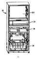
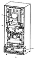
図1は、本発明の一実施例に係る冷蔵冷凍装置の模式的な構造図である。図2は、図1に示す構造の別の視角での模式的な構造図である。図1と図2に示すように、本発明の実施例は、冷蔵冷凍装置を提供する。当該冷蔵冷凍装置は、筐体20、主扉、ガス調整膜ユニット30、吸気ポンプ41と冷却システムを備えてもよい。
FIG. 1 is a schematic structural diagram of a refrigerating / freezing device according to an embodiment of the present invention. FIG. 2 is a schematic structural diagram of the structure shown in FIG. 1 at another viewing angle. As shown in FIGS. 1 and 2, the embodiments of the present invention provide a refrigerating / freezing device. The refrigerating / freezing device may include a
筐体20内には、収納空間211および圧縮機室24が規定されている。例えば、筐体20は、内箱21を備えてもよく、内箱21内には、収納空間211が区画されている。主扉は、2つの観音開き扉によって構成され、何れも筐体20に回動可能に配置されてもよく、筐体20で規定される収納空間211を開放または閉鎖するように構成される。好ましくは、主扉は、1つのドアであってもよい。さらに、収納空間211内には、収納容器が配置され、収納容器内は、ガス調整鮮度保持空間を有する。ガス調整鮮度保持空間は、密閉型空間または略密閉型空間であってもよい。好ましくは、収納容器は、引き出しユニットである。収納容器は、引き出し筒体22および引き出し本体23を備えてもよい。引き出し筒体22は、前向き開口を有してもよく、且つ収納空間211内に配置され、具体的に収納空間211の下部に配置されてもよい。当業者であれば意識できるように、引き出し筒体22は、収納空間211の中部または上部に配置されてもよい。引き出し本体23は、引き出し筒体22内にスライド可能に配置されることにより、引き出し筒体22の前向き開口から操作可能に外方へ抽出したり、内方へ引き出し筒体22を挿入したりする。引き出し本体23は、引き出し端蓋を備えてもよい。引き出し端蓋は、引き出し筒体22の開口に係合することにより、ガス調整鮮度保持空間の密閉を行ってもよい。幾つかの代替実施例では、収納容器は、筒体と、筒体を開放または閉鎖するように構成される小扉とを備えてもよい。
A
冷却システムは、圧縮機、凝縮器、絞り装置および蒸発器等によって構成される冷却循環システムであってもよい。圧縮機は、圧縮機室24内に取り付けられている。蒸発器は、直接または間接に収納空間211内へ冷気を供給するように配置される。例えば、当該冷蔵冷凍装置が家庭用圧縮式直冷冷蔵庫であるとき、蒸発器は、内箱21の後壁面の外側まはた内側に配置されてもよい。当該冷蔵冷凍装置が家庭用圧縮式空冷冷蔵庫であるとき、筐体20内には、蒸発器室が更に配置され、蒸発器室が風路システムを介して収納空間211に連通し、且つ蒸発器室内に蒸発器が配置され、出口にファンが配置されることにより、収納空間211に対して循環冷却を行う。
The cooling system may be a cooling circulation system composed of a compressor, a condenser, a drawing device, an evaporator and the like. The compressor is installed in the
ガス調整膜ユニット30は、少なくとも1つのガス調整膜31と1つの酸素富化ガス収集室を備え、その周囲空間がガス調整鮮度保持空間に連通する。当該ガス調整膜ユニット30は、ガス調整膜ユニット30の周囲空間の気流における酸素ガスがガス調整膜ユニット30の周囲空間の気流における窒素ガスよりもガス調整膜31を多く透過して酸素富化ガス収集室に進入するように構成されてもよい。具体的に、各ガス調整膜31の内側表面は、酸素富化ガス収集室へ向かうことにより、酸素富化ガス収集室の圧力がガス調整膜ユニット30の周囲空間の圧力より小さいときに、ガス調整膜ユニット30の外部空間の空気における酸素ガスがその中の窒素ガスよりも少なくとも1つのガス調整膜31を多く透過して酸素富化ガス収集室に進入する。
The gas adjusting membrane unit 30 includes at least one
吸気ポンプ41も圧縮機室24内に配置され、吸気ポンプ41の入口端が管路50を介してガス調整膜ユニット30の酸素富化ガス収集室に連通することにより、酸素富化ガス収集室内に透入したガスを収納容器外へ引き抜く。
The intake pump 41 is also arranged in the
当該実施例では、吸気ポンプ41が外方へガスを抽出することにより、酸素富化ガス収集室の圧力をガス調整膜ユニット30の周囲空間の圧力より小さくでき、さらに、ガス調整膜ユニット30の周囲空間内の酸素ガスを酸素富化ガス収集室に進入させることも可能である。ガス調整鮮度保持空間がガス調整膜ユニット30の周囲空間に連通するため、ガス調整鮮度保持空間内の空気がガス調整膜ユニット30の周囲空間に進入する。よって、ガス調整鮮度保持空間内の空気中の酸素ガスを酸素富化ガス収集室に進入させることで、ガス調整鮮度保持空間内を窒素富化酸素欠損状態として食物鮮度保持に有利な雰囲気にさせる。 In the embodiment, the pressure of the oxygen-enriched gas collection chamber can be made smaller than the pressure of the surrounding space of the gas adjusting membrane unit 30 by extracting the gas to the outside by the intake pump 41, and further, the pressure of the gas adjusting membrane unit 30 can be reduced. It is also possible to allow oxygen gas in the surrounding space to enter the oxygen-enriched gas collection chamber. Since the gas adjusting freshness holding space communicates with the surrounding space of the gas adjusting membrane unit 30, the air in the gas adjusting freshness holding space enters the surrounding space of the gas adjusting membrane unit 30. Therefore, by letting the oxygen gas in the air in the gas-adjusted freshness-retaining space enter the oxygen-enriched gas collection chamber, the gas-adjusted freshness-retaining space is made into a nitrogen-enriched oxygen-deficient state to create an atmosphere advantageous for maintaining food freshness. ..
本発明の冷蔵冷凍装置は、ガス調整鮮度保持空間内を窒素富化酸素欠損状態として食品鮮度保持に有利な雰囲気にさせることが可能である。当該雰囲気は、果物・野菜保存空間内の酸素ガスの含有量を低減し、果物・野菜の酸素呼吸の強度を低減しつつ、基礎的な呼吸作用を保証して果物・野菜の無酸素呼吸を防止することにより、果物・野菜の長期間に渡る鮮度保持の目的を果す。また、当該雰囲気は、大量の窒素ガス等の気体を有するため、ガス調整鮮度保持空間内の物品の冷却受け効率を低減せず、果物・野菜の有効な収納を可能にする。吸気ポンプ41が圧縮機室24内に配置されるため、圧縮機室24の空間を十分に利用可能であり、他の箇所を別途占用しないため、冷蔵冷凍装置の余分な体積が増大されず、冷蔵冷凍装置の構造は、コンパクトにできる。そして、筐体20等の剛性や強度に対する要求も低く、実現要求が非常に低く、コストも非常に低い。本発明の冷蔵冷凍装置は、ガス調整鮮度保持分野の技術者がずっと解決しようとするが未だに解決できていない上記技術的難関を解決した。本発明の冷蔵冷凍装置は、体積が小さく、ノイズも低いため、特に家庭と個人に向いている。
The refrigerating / freezing device of the present invention can create a nitrogen-enriched oxygen-deficient state in the gas-adjusted freshness-maintaining space to create an atmosphere advantageous for maintaining food freshness. The atmosphere reduces the content of oxygen gas in the fruit / vegetable storage space, reduces the intensity of oxygen breathing of fruits / vegetables, and guarantees basic respiration to ensure anoxic breathing of fruits / vegetables. By preventing it, it serves the purpose of maintaining the freshness of fruits and vegetables for a long period of time. Further, since the atmosphere has a large amount of gas such as nitrogen gas, it does not reduce the cooling receiving efficiency of the article in the gas-adjusted freshness holding space, and enables effective storage of fruits and vegetables. Since the intake pump 41 is arranged in the
本発明の幾つかの実施例では、引き出し筒体22には、複数のマイクロポアが設けられてもよく、収納空間211とガス調整鮮度保持空間とは、複数のマイクロポアを介して連通される。マイクロポアは、気圧バランス孔とも呼ばれ、各マイクロポアは、ミリメートルオーダーのマイクロポアであってもよい。例えば、各マイクロポアの直径は、0.1mm〜3mmであり、1mm、1.5mm等であることが好ましい。複数のマイクロポアを設けると、ガス調整鮮度保持空間内の圧力は、低すぎなくなる。複数のマイクロポアを設けることによってでも、ガス調整鮮度保持空間内の窒素ガスが大きな収納空間211へ流れることはない。たとえ流れても、微小であり、引いては無視でき、ガス調整鮮度保持空間内での食品の保存に影響しない。本発明の幾つかの好適な実施例では、引き出し筒体22には、マイクロポアが設けられなくてもよい。それにしても、ガス調整鮮度保持空間内には、大量の窒素ガス等のガスがまだ存在する。ユーザは、引き出し本体23を開く際、そんなに苦労しなくてもよく、従来の真空収納室より、大きく省力化される。
In some embodiments of the present invention, the
本発明の幾つかの実施例では、収納空間211は、冷蔵空間であり、その貯蔵温度が一般的に2℃〜10℃であり、3℃〜8℃であることが好ましい。さらに、筐体20には、冷凍空間25と変温空間26が更に規定されてもよく、冷凍空間25は、収納空間211の下方に設けられ、変温空間26は、冷凍空間25と冷蔵空間の間に設けられている。冷凍空間25内の温度範囲は、一般的に−14℃〜−22℃である。変温空間26は、適切な食品を貯蔵するように、需要に応じて調整可能である。圧縮機室24は、好ましくは、冷凍空間25の後下方に設けられている。本発明の幾つかの代替実施例では、収納空間211も冷凍空間または変温空間であってもよい。つまり、収納空間211の温度範囲は、−14℃〜−22℃に制御されてもよく、または、需要に応じて調整されてもよい。さらに、冷蔵空間と冷凍空間と変温空間との相対位置は、実際の需要に応じて調整可能である。
In some embodiments of the present invention, the
本発明の幾つかの実施例では、圧縮機室24は、筐体20の横方向に沿って延在し、吸気ポンプ41は、圧縮機室24の横方向の一方端に配置されている。圧縮機は、圧縮機室24の横方向の他方端に配置されてもよい。これにより、吸気ポンプ41と圧縮機との距離が遠くて、ノイズ重畳と廃熱重畳が減少される。例えば、吸気ポンプ41は、圧縮機室24の主扉回動側に近接する端に配置されてもよい。冷蔵冷凍装置が観音開き型冷蔵庫であるとき、吸気ポンプ41は、圧縮機室24の何れか一端に配置されてもよい。本発明の別の実施例では、吸気ポンプ41は、圧縮機に近接するように配置され、吸気ポンプ41は、圧縮機室24の一方端に配置され、且つ圧縮機と圧縮機室24の側壁との間に位置する。
In some embodiments of the present invention, the
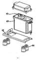
図3は、本発明の一実施例に係る冷蔵冷凍装置における吸気ポンプユニットの模式的な分解図である。図3に示すように、本発明の幾つかの実施例では、冷蔵冷凍装置は、取付底板42とシールボックス43を更に備えてもよい。取付底板42は、複数の制振パッド44を介して圧縮機室24の底面に取り付けられてもよい。シールボックス43は、取付底板42に取り付けられている。吸気ポンプ41は、シールボックス43内に取り付けられている。つまり、吸気ポンプ41は、1つのシールボックス43の内部に取り付けられてもよく、シールボックス43は、取付底板42を介して圧縮機室24内に取り付けられてもよい。シールボックス43、取付底板42と吸気ポンプ41は、吸気ポンプユニット40とも呼ばれてもよい。吸気ポンプ41の運転時、シールボックス43は、ノイズ及び/又は廃熱の外方への伝搬を大きく遮断することができる。さらに、制振・ノイズ低減効果が向上するように、取付底板42には、複数の制振パッド44(ゴム材質であってもよい)が配置されてもよい。制振パッド44の数は、4つであることが好ましく、4つの制振パッド44は、取付底板42の4隅に設けられたパッド取り付け穴内に実装される。
FIG. 3 is a schematic exploded view of an intake pump unit in a refrigerator / freezer according to an embodiment of the present invention. As shown in FIG. 3, in some embodiments of the present invention, the refrigerating / freezing device may further include a mounting bottom plate 42 and a seal box 43. The mounting bottom plate 42 may be mounted on the bottom surface of the
本発明の幾つかの実施例では、シールボックス43の内部には、1つの取付フレームが配置され、取付フレームとシールボックス43の内壁とは、複数の制振パッドを介して接続され、吸気ポンプ41は、取付フレームの内部に固定されている。このようにして、吸気ポンプ41の運転時における振動およびノイズを低減する。具体的に、取付フレームの底部には、2つの制振パッドが配置され、制振パッドは、シールボックス43の底面の位置決め柱に外装されている。取付フレームの一方の対向する両側には、1つずつの円形の制振パッドが配置され、当該制振パッドは、シールボックス43の該当する側壁の係合溝内に係止される。取付フレームの他方の対向する両側には、1つずつの制振パッドが固定される。吸気ポンプ41は、シールボックス43内の各制振パッドの間に位置し、ネジを介して取付フレームに締め付けられてもよい。 In some embodiments of the present invention, one mounting frame is arranged inside the seal box 43, and the mounting frame and the inner wall of the seal box 43 are connected via a plurality of vibration damping pads to form an intake pump. 41 is fixed to the inside of the mounting frame. In this way, vibration and noise during operation of the intake pump 41 are reduced. Specifically, two damping pads are arranged at the bottom of the mounting frame, and the damping pads are exteriorized by a positioning column on the bottom surface of the seal box 43. One circular damping pad is arranged on one opposite side of the mounting frame, and the damping pad is locked in the engaging groove of the corresponding side wall of the seal box 43. One damping pad is fixed to each of the other opposite sides of the mounting frame. The intake pump 41 may be located between the damping pads in the seal box 43 and may be fastened to the mounting frame via screws.
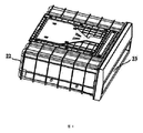
本発明の幾つかの実施例では、図4と図5に示すように、ガス調整膜ユニット30は、引き出し筒体22の筒体壁に配置されてもよい。ガス調整膜ユニット30は、平板型であり、好ましくは、引き出し筒体22の天壁に平行となるように配置されている。具体的に、引き出し筒体22の天壁内には、収容室221が設けられてガス調整膜ユニット30を収容する。例えば、引き出し筒体22の天壁の収容室とガス調整鮮度保持空間との間の壁面には、少なくとも1つの第1通気孔222および第2通気孔223が設けられている。少なくとも1つの第1通気孔222は、少なくとも1つの第2通気孔223と間隔をおいて設けられることにより、それぞれ異なる位置において収容室とガス調整鮮度保持空間とを連通させる。第1通気孔222と第2通気孔223は、何れも小孔であり、数が何れも複数である。幾つかの代替実施例では、引き出し筒体22の天壁内側は、凹溝を有する。ガス調整膜ユニット30は、引き出し筒体22の天壁の凹溝内に配置されている。
In some embodiments of the present invention, as shown in FIGS. 4 and 5, the gas adjusting membrane unit 30 may be arranged on the cylinder wall of the
管路50は、上から下へ延在する垂直セグメントを備えてもよい。垂直セグメントは、収納空間211の後方に配置され、且つ垂直セグメントの下端が吸気ポンプ41の入口に連通し、垂直セグメントの上方がガス調整膜ユニット30の酸素富化ガス収集室に連通する。垂直セグメントは、筐体20におけるサイドケースとバックプレートとに近接するように配置されてもよく、垂直セグメントには、保温ジャケットまたは保温管が外装されてもよい。これにより、垂直セグメント内の酸素ガスにおける冷却量がサイドケースとバックプレートとに伝達されることは、回避可能であり、結露の発生も防止できる。
The pipeline 50 may include vertical segments that extend from top to bottom. The vertical segment is arranged behind the
本発明の幾つかの実施例では、ガス調整鮮度保持空間と収容室221内のガス流動を促進するために、冷蔵冷凍装置は、ファン60を更に備えてもよい。ファン60は、収容室内に配置されてもよく、ガス調整鮮度保持空間のガスが第1通気孔222を経由して収容室221に進入することを促進し、且つ収容室221内のガスが第2通気孔223を経由してガス調整鮮度保持空間に進入することを促進するように構成される。つまり、ファン60は、ガス調整鮮度保持空間のガスが順次少なくとも1つの第1通気孔222、収容室及び少なくとも1つの第2通気孔223を経由してガス調整鮮度保持空間に戻ることを促進可能である。
In some embodiments of the present invention, the refrigerating / freezing device may further include a fan 60 to facilitate gas flow in the gas regulated freshness holding space and the containment chamber 221. The fan 60 may be arranged in the accommodation chamber to promote the gas in the gas-adjusted freshness holding space from entering the accommodation chamber 221 via the
ファン60は、遠心ファンであることが好ましく、収容室221内の第1通気孔222に配置されている。つまり、遠心ファンは、少なくとも1つの第1通気孔222の上方に位置し、且つ回転軸線が鉛直下方へ向かい、吸気口が第1通気孔222に正対する。遠心ファンの排気口は、ガス調整膜ユニット30へ向かってもよい。ガス調整膜ユニット30は、少なくとも1つの第2通気孔223の上方に配置され、ガス調整膜ユニット30の各ガス調整膜が引き出し筒体22の天壁に平行となるようにする。少なくとも1つの第1通気孔222は、天壁前部に設けられ、少なくとも1つの第2通気孔223は、天壁後部に設けられている。即ち、遠心ファン60は、収容室221の前部に配置され、ガス調整膜ユニット30は、収容室221の後部に配置されている。さらに、引き出し筒体22の天壁は、主板部224および蓋板部225を備え、主板部224の一部の領域には凹部が形成され、蓋板部225は、凹部を取り外し可能に覆うことにより、上記収容室221を形成する。引き出し筒体22の製造が便利になるように、主板部224は、引き出し筒体22の側壁、底壁および後壁と一体成形されてもよい。
The fan 60 is preferably a centrifugal fan and is arranged in the
本発明の幾つかの実施例では、図6に示すように、ガス調整膜ユニット30は、平板型であってもよく、当該ガス調整膜ユニット30は、支持フレーム32を更に備えてもよい。ガス調整膜31は、酸素富化膜であることが好ましく、2つあってもよく、支持フレーム32の両側に取り付けられることにより、2つのガス調整膜31と支持フレーム32とが共同して酸素富化ガス収集室を取り囲む。さらに、支持フレーム32は、ベゼル、ベゼル内に配置されるリブ板及び/又は平板等の構造を備えてもよい。リブ板の間、リブ板と平板の間等には、気流通路が形成されてもよく、リブ板の表面と平板の表面の何れにも、気流通路を形成するように、凹溝が設けられてもよい。リブ板及び/又は平板は、ガス調整膜ユニット30の構造強度等を向上可能である。つまり、支持フレーム32は、互いに平行となる第1表面と第2表面を有し、且つ支持フレーム32には、第1表面に延在する気流通路、第2表面に延在する気流通路、および支持フレーム32を貫通して第1表面と第2表面とを連通させる気流通路という複数の気流通路がそれぞれ形成され、複数の気流通路は、共同して酸素富化ガス収集室を形成する。少なくとも1つのガス調整膜31は、2つの平面型ガス調整膜であり、それぞれ支持フレーム32の第1表面と第2表面とに敷設されている。
In some embodiments of the present invention, as shown in FIG. 6, the gas adjusting membrane unit 30 may be of a flat plate type, and the gas adjusting membrane unit 30 may further include a
本発明の幾つかの実施例では、支持フレーム32は、上記少なくとも1つの気流通路に連通するガス抜き孔33を備え、ガス抜き孔33は、ベゼルに設けられて酸素富化ガス収集室における酸素ガスの出力を許容する。ガス抜き孔33は、吸気ポンプ41に連通する。ガス抜き孔33は、ガス調整膜ユニット30の設置方位または実際の設計需要に応じて特定可能であるように、ベゼルの長辺の縁に設けられてもよく、ベゼルの短辺の縁に設けられてもよい。例えば、図4と図5に示す実施例では、ガス抜き孔33は、ベゼルの長辺の縁に設けられてもよい。ガス調整膜31は、両面テープ34を介してベゼルに取り付けられてから、シーラ35を介して密封される。
In some embodiments of the present invention, the
幾つかの実施例では、支持フレーム32は、ベゼル、複数の第1リブ板および複数の第2リブ板を備えてもよい。上記複数の第1リブ板は、ベゼル内部で縦方向に間隔をおいて配置され且つ横方向に延在し、上記複数の第1リブ板の一方側の表面が第1表面を形成する。複数の第2リブ板は、上記複数の第1リブ板の他方側の表面で横方向に間隔をおいて配置され且つ縦方向に沿って延在し、上記複数の第2リブ板の第1リブ板から離隔する側の表面が第2表面を形成する。本発明の支持フレーム32は、そのベゼル内に、縦方向に間隔をおいて且つ横方向に沿って延在する複数の第1リブ板と、上記複数の第1リブ板の一方側の表面に横方向に間隔をおいて且つ縦方向に沿って延在する複数の第2リブ板とを設けることにより、気流通路の一貫性を保証する一方、支持フレーム32の体積を大きく縮小し、支持フレーム32の強度を極めて大きく向上させる。また、支持フレーム32の上記構造は、ガス調整膜31が十分な支持を得ることを保証し、酸素富化ガス収集室の内部負圧が大きい場合にも良好な平坦度を常に保ち、ガス調整膜ユニット30の使用寿命を保証する。
In some embodiments, the
更なる実施例では、上記複数の第1リブ板は、複数の第1狭リブ板と複数の第1広リブ板を備えてもよい。その中、複数の第1広リブ板は、間隔をおいて配置され、隣り合う2つの第1広リブ板の間には、複数の第1狭リブ板が配置されている。上記複数の第2リブ板は、複数の第2狭リブ板および複数の第2広リブ板を含んでもよく、複数の第2広リブ板は、間隔をおいて配置され、隣り合う2つの第2広リブ板の間には、複数の第2狭リブ板が配置されている。当業者であれば理解やすいように、ここでの「広」と「狭」は、相対的に言う概念である。 In a further embodiment, the plurality of first rib plates may include a plurality of first narrow rib plates and a plurality of first wide rib plates. Among them, a plurality of first wide rib plates are arranged at intervals, and a plurality of first narrow rib plates are arranged between two adjacent first wide rib plates. The plurality of second rib plates may include a plurality of second narrow rib plates and a plurality of second wide rib plates, and the plurality of second wide rib plates are arranged at intervals and two adjacent second plates are provided. A plurality of second narrow rib plates are arranged between the two wide rib plates. For those skilled in the art to understand, "wide" and "narrow" here are relative concepts.
幾つかの実施例では、各第1広リブ板は、第1表面を形成する一方側表面から内方へ窪んで第1トレンチを形成し、各第2広リブ板は、第2表面を形成する一方側表面から内方へ窪んで第2トレンチを形成する。これにより、支持フレーム32の厚みが非常に小さい(または、体積が非常に小さい)ことを保証した前提で、その内部グリッド構造の連通性が向上する。
In some embodiments, each first wide rib plate is recessed inward from one side surface forming the first surface to form a first trench, and each second wide rib plate forms a second surface. A second trench is formed by denting inward from the surface on one side. This improves the connectivity of the internal grid structure on the premise that the thickness of the
更なる実施例では、各第1広リブ板の第1表面から離反する一部の表面が第2リブ板へ向かって第2表面に揃うまで延在し、且つ第2表面に揃う当該一部の表面から内方へ窪んで第3トレンチを形成する。第3トレンチと第2トレンチとが交差する箇所は、連通されて十字トレンチを形成する。上記複数の第2広リブ板のうち、少なくとも1つの第2広リブ板の第2表面から離反する一部の表面は、第1リブ板へ向かって第1表面に揃うまで延在し、第1表面に揃う当該一部の表面は、内方へ窪んで第4トレンチを形成する。ただし、第4トレンチと第1トレンチとが交差する箇所は、連通されて十字トレンチを形成する。 In a further embodiment, a portion of each first wide rib plate that separates from the first surface extends toward the second rib plate until it aligns with the second surface, and the portion aligns with the second surface. It is recessed inward from the surface of the surface to form a third trench. The intersections of the third trench and the second trench are communicated to form a cross trench. Of the plurality of second wide rib plates, a part of the surface of at least one of the second wide rib plates separated from the second surface extends toward the first rib plate until it is aligned with the first surface, and the first surface is aligned. The part of the surface aligned with one surface is recessed inward to form a fourth trench. However, the points where the fourth trench and the first trench intersect are communicated to form a cross trench.
本発明の幾つかの実施例では、気流の流動が便利になるように、蓋板部225の内面が下方へ延在して複数の導風リブ板を形成してもよい。こうして、ファン60からの気流が収容室内でガス調整膜ユニット30の各ガス調整膜31の酸素富化ガス収集室から離反する外側表面を流れるように案内する。複数の導風リブ板は、2群に分けられてもよい。その2群の導風リブ板は、第1群の導風リブ板と、第1群の導風リブ板とは1つの平面について対称に配置された第2群の導風リブ板とを含む。各群の導風リブ板は、第1導風リブ板、少なくとも1つの第2導風リブ板および少なくとも1つの第3導風リブ板を含む。第1導風リブ板は、遠心ファンの排気口から収容室の一方側へ延在し、且つガス調整膜ユニット30の1つの横方向外側まで延在する。第2導風リブ板のそれぞれは、2つの第1導風リブ板の間に配置され、且つガス調整膜ユニット30と遠心ファンの間に位置する。第3導風リブ板のそれぞれがガス調整膜ユニット30の1つの横方向外側に位置することにより、気流がガス調整膜ユニット30の横方向両側からガス調整膜ユニット30と収容室の底面或いは天面との間の隙間に進入するように気流を案内する。
In some embodiments of the present invention, the inner surface of the lid plate portion 225 may extend downward to form a plurality of wind guide rib plates so that the flow of airflow becomes convenient. In this way, the airflow from the fan 60 is guided to flow in the accommodation chamber on the outer surface of each
本発明の幾つかの実施例では、引き出し本体23と引き出し筒体22の間には、ロック装置、ハンドルとハンドル位置決め装置が配置されている。ロック装置は、引き出し端蓋両側に配置される回動ロックキャッチと、引き出し筒体22に設けられる2つの係合部と、係止促進装置とを備える。係合部のそれぞれは、突起であってもよい。係止促進装置は、2つの回動ロックキャッチがそれぞれに対応する係合部に係止される方向(即ち、各自の第1方向)へ向かって回動するように促進するために用いられてもよい。ハンドルは、水平に延在し、且つ鉛直方向に沿って引き出し端蓋にスライド可能に取り付けられてもよい。また、引き出し本体23が閉じる状態であるときに、ハンドルの所在する位置は、ハンドルの初期位置であってもよい。ハンドルは、その初期位置に配置されるときに、その両端がそれぞれ2つの回動ロックキャッチに接触して当接することにより、各回動ロックキャッチがそれぞれに対応する第1方向とは反対する別の方向に沿って回動することを阻止する。これにより、前記回動ロックキャッチと前記係合部とが係合状態を保ち、前記引き出し本体23を前記引き出し筒体22にロッキングさせる。さらに、ハンドルが上方または下方へロック保持解除位置まで移動し、即ち、初期位置からロック保持解除位置まで移動した後、各回動ロックキャッチがそれぞれに対応する第1方向とは反対する別の方向に沿って回動することを許容することにより、外方へ引き出し本体23を引き出すことを許容するときに、回動ロックキャッチは、回動して対応する係合部から離脱する。こうして、引き出し本体23を開くことは、許容される。ハンドル位置決め装置は、ハンドルが各所定位置まで移動した後、ハンドルを当該位置に保持するように構成され、当該位置は、主に初期位置とロック保持解除位置である。引き出し本体を開く際、ユーザは、まずハンドルを上方或いは下方へロック保持解除位置まで移動させて、ハンドル位置決め装置によってハンドルを当該位置に維持させ、ユーザは、外方へ引き出し本体23を引き出せる。引き出しを閉じる際、ユーザは、まず、引き出し本体23を閉じ、その後ハンドルを下方或いは上方へ初期位置まで戻らせ、ハンドル位置決め装置によってハンドルを当該位置に維持させる。これにより、引き出し本体23と引き出し筒体22とは、ロック状態を保持する。
In some embodiments of the present invention, a lock device, a handle and a handle positioning device are arranged between the drawer
ハンドルの移動がより安定するように、ハンドルの両端には、それぞれガイドロッドおよび摺動ブロックが更に配置されている。ガイドロッドは、鉛直方向に沿って延在する。引き出し本体23は、2群のスライドガイドを更に備え、各群のスライドガイドは、少なくとも3つの鉛直方向に沿って延在するスライドスロットを有することにより、ガイドロッドの両側のそれぞれが1つのスライドスロットを有し、摺動ブロックが他のスライドスロットに移動し、または、摺動ブロックの両側のそれぞれが1つのスライドスロットを有し、ガイドロッドが他のスライドスロットに移動する。例えば、各群のスライドガイドは、4つのスライドスロットを備えてもよく、ガイドロッドの前後両側は、それぞれ1つのスライドスロットを有し、摺動ブロックの横方向両側(即ち、左右両側)のそれぞれは、1つのスライドスロットを有する。
Guide rods and sliding blocks are further arranged at both ends of the handle so that the movement of the handle is more stable. The guide rod extends along the vertical direction. The
これまでに、当業者であれば分かるように、本発明の複数の例示的な実施例が本文に詳細に示されて記述されてきたが、本発明の要旨及び範囲を逸脱しない限り、本発明に開示された内容から本発明の原理に合致する大量の他の変形や改良を直接特定或いは推論することが可能である。したがって、本発明の範囲がこれらの他の変形や改良を全てカバーするとは、理解及び認定されるべきである。 So far, a plurality of exemplary embodiments of the present invention have been described in detail in the text, as will be appreciated by those skilled in the art, but the present invention will not deviate from the gist and scope of the present invention. It is possible to directly identify or infer a large number of other modifications and improvements that are consistent with the principles of the present invention from the contents disclosed in. Therefore, it should be understood and acknowledged that the scope of the invention covers all of these other modifications and improvements.
Claims (7)
前記筐体内には、収納空間と圧縮機室とが規定され、前記収納空間内には、収納容器が配置され、前記収納容器内は、ガス調整鮮度保持空間を有し、
前記ガス調整膜ユニットは、少なくとも1つのガス調整膜と、1つの酸素富化ガス収集室とを備え、その周囲空間が前記ガス調整鮮度保持空間に連通し、前記ガス調整膜ユニットは、前記ガス調整膜ユニットの周囲空間の気流における酸素ガスが前記ガス調整膜ユニットの周囲空間の気流における窒素ガスよりも前記ガス調整膜を多く透過して前記酸素富化ガス収集室に進入するように構成され、
前記吸気ポンプは、前記圧縮機室内に配置され、前記吸気ポンプの入口端が管路を介して前記ガス調整膜ユニットの前記酸素富化ガス収集室に連通することにより、前記酸素富化ガス収集室内に透入したガスを前記収納容器外へ引き抜き、
前記収納容器は、引き出しユニットであり、引き出し筒体と、引き出し本体とを備え、
前記引き出し筒体は、前向き開口を有し、前記収納空間内に配置され、
前記引き出し本体は、前記引き出し筒体内にスライド可能に取り付けられることにより、前記引き出し筒体の前向き開口から、操作可能に外方へ抽出されたり、内方へ前記引き出し筒体に挿入されたりし、
前記引き出し筒体の天壁内には、前記ガス調整鮮度保持空間に連通する収容室が配置されて前記ガス調整膜ユニットを収容し、
前記引き出し筒体の天壁の前記収容室と前記ガス調整鮮度保持空間との間の壁面には、少なくとも1つの第1通気孔と、少なくとも1つの前記第1通気孔に間隔をおいた少なくとも1つの第2通気孔とが設けられることにより、それぞれ異なる位置において前記収容室と前記ガス調整鮮度保持空間とを連通させ、
前記冷蔵冷凍装置は、ファンを更に備え、前記ファンは、前記収容室内に配置され、前記ガス調整鮮度保持空間のガスが順次前記少なくとも1つの第1通気孔、前記収容室および前記少なくとも1つの第2通気孔を経由して前記ガス調整鮮度保持空間に戻ることを促進することを特徴とする冷蔵冷凍装置。 It is equipped with a housing, a gas adjustment membrane unit, and an intake pump.
A storage space and a compressor room are defined in the housing, a storage container is arranged in the storage space, and the storage container has a gas-adjusted freshness holding space.
The gas adjusting membrane unit includes at least one gas adjusting membrane and one oxygen-enriched gas collecting chamber, and the surrounding space thereof communicates with the gas adjusting freshness holding space, and the gas adjusting membrane unit is the gas. It is configured so that the oxygen gas in the airflow in the space around the adjusting membrane unit permeates the gas adjusting membrane more than the nitrogen gas in the airflow in the surrounding space of the gas adjusting membrane unit and enters the oxygen-enriched gas collection chamber. ,
The intake pump is arranged in the compressor chamber, and the oxygen-enriched gas collection is performed by communicating the inlet end of the intake pump with the oxygen-enriched gas collection chamber of the gas adjusting membrane unit via a pipeline. the ToruIri gas into the room pulling unplug to the container outside,
The storage container is a drawer unit, and includes a drawer cylinder and a drawer body.
The drawer cylinder has a forward opening and is arranged in the storage space.
By being slidably attached to the inside of the drawer cylinder, the drawer body can be operably extracted outward from the forward opening of the drawer cylinder or inserted inward into the drawer cylinder.
In the top wall of the drawer cylinder, a storage chamber communicating with the gas adjustment freshness holding space is arranged to accommodate the gas adjustment membrane unit.
At least on the wall surface between said housing chamber of the top wall of the front Symbol drawer cylinder the gas adjusting freshness retaining space, placed and at least one first vent hole, a gap in at least one of said first vent hole By providing one second vent, the accommodation chamber and the gas-adjusted freshness holding space can be communicated with each other at different positions.
The refrigerating / freezing device further includes a fan, the fan is arranged in the storage chamber, and the gas in the gas-adjusted freshness holding space is sequentially provided with the at least one first vent, the storage chamber, and the at least one first. 2 A refrigerating / freezing device characterized in promoting the return to the gas-adjusted freshness-retaining space via a vent .
複数の制振パッドを介して前記圧縮機室の底面に取り付けられた取付底板と、
前記取付底板に取り付けられたシールボックスと、を更に備え、
前記吸気ポンプは、前記シールボックス内に取り付けられていることを特徴とする請求項3に記載の冷蔵冷凍装置。 The refrigerating / freezing device
A mounting bottom plate mounted on the bottom surface of the compressor chamber via a plurality of damping pads,
Further provided with a seal box attached to the mounting bottom plate,
The refrigerating / freezing device according to claim 3 , wherein the intake pump is mounted in the seal box.
前記筐体には、冷凍空間と変温空間とが更に規定され、前記冷凍空間は、前記収納空間の下方に設けられ、前記変温空間は、前記冷凍空間と前記冷蔵空間の間に設けられ、
前記圧縮機室は、前記冷凍空間の後下方に設けられていることを特徴とする請求項3に記載の冷蔵冷凍装置。 The storage space is a refrigerated space and
A refrigerating space and a temperature changing space are further defined in the housing, the refrigerating space is provided below the storage space, and the temperature changing space is provided between the refrigerating space and the refrigerating space. ,
The refrigerating / freezing device according to claim 3 , wherein the compressor chamber is provided below the rear of the freezing space.
前記少なくとも1つのガス調整膜は、2つの平面型ガス調整膜であり、前記支持フレームの第1表面と第2表面とにそれぞれ敷設されていることを特徴とする請求項1に記載の冷蔵冷凍装置。 The gas adjusting membrane unit further includes a support frame, the support frame having a first surface and a second surface parallel to each other, and the support frame has an air flow passage extending to the first surface. , A plurality of air passages extending to the second surface and an air passage that penetrates the support frame and communicates the first surface and the second surface are formed, and the plurality of air passages are formed. , Jointly formed the oxygen-enriched gas collection chamber,
The refrigerated refrigeration according to claim 1, wherein the at least one gas adjusting film is two planar gas adjusting films, which are laid on the first surface and the second surface of the support frame, respectively. apparatus.
Applications Claiming Priority (3)
| Application Number | Priority Date | Filing Date | Title |
|---|---|---|---|
| CN201611097680.9 | 2016-12-02 | ||
| CN201611097680.9A CN106524644B (en) | 2016-12-02 | 2016-12-02 | Refrigerating device |
| PCT/CN2017/114215 WO2018099462A1 (en) | 2016-12-02 | 2017-12-01 | Refrigerating and freezing device |
Publications (2)
| Publication Number | Publication Date |
|---|---|
| JP2019536974A JP2019536974A (en) | 2019-12-19 |
| JP6817439B2 true JP6817439B2 (en) | 2021-01-20 |
Family
ID=58354699
Family Applications (1)
| Application Number | Title | Priority Date | Filing Date |
|---|---|---|---|
| JP2019529923A Active JP6817439B2 (en) | 2016-12-02 | 2017-12-01 | Refrigerator |
Country Status (10)
| Country | Link |
|---|---|
| US (1) | US11268747B2 (en) |
| EP (1) | EP3550228B1 (en) |
| JP (1) | JP6817439B2 (en) |
| KR (1) | KR102209635B1 (en) |
| CN (1) | CN106524644B (en) |
| AU (1) | AU2017369104B2 (en) |
| ES (1) | ES2913533T3 (en) |
| PL (1) | PL3550228T3 (en) |
| RU (1) | RU2722545C1 (en) |
| WO (1) | WO2018099462A1 (en) |
Families Citing this family (5)
| Publication number | Priority date | Publication date | Assignee | Title |
|---|---|---|---|---|
| CN106524644B (en) | 2016-12-02 | 2019-10-01 | 青岛海尔股份有限公司 | Refrigerating device |
| JP6986482B2 (en) * | 2018-04-09 | 2021-12-22 | 東芝ライフスタイル株式会社 | Storage |
| CN114165978B (en) * | 2020-09-11 | 2023-05-16 | 青岛海尔电冰箱有限公司 | Control method of refrigerator |
| US11268750B1 (en) * | 2020-12-23 | 2022-03-08 | Electrolux Home Products, Inc. | On door drawer and refrigerating appliance with same |
| US11932000B2 (en) * | 2021-03-23 | 2024-03-19 | Whirlpool Corporation | Refrigerator having a membrane |
Family Cites Families (27)
| Publication number | Priority date | Publication date | Assignee | Title |
|---|---|---|---|---|
| US3256675A (en) * | 1962-11-30 | 1966-06-21 | Gen Electric | Method and apparatus for gas separation by thin films or membranes |
| JPS5164964U (en) * | 1974-11-18 | 1976-05-21 | ||
| DE3413552A1 (en) * | 1984-04-11 | 1985-10-24 | Hansa Metallwerke Ag, 7000 Stuttgart | SHOWER |
| JP2602427B2 (en) * | 1987-02-23 | 1997-04-23 | 鈴木総業株式会社 | Refrigeration equipment |
| JPH03285668A (en) * | 1990-03-30 | 1991-12-16 | Sharp Corp | Food preservation vessel |
| JPH0522781A (en) * | 1991-07-15 | 1993-01-29 | Matsushita Electric Works Ltd | Remote monitoring control system |
| JPH0549460A (en) * | 1991-08-26 | 1993-03-02 | Sharp Corp | Preservation chamber |
| JPH05227881A (en) * | 1992-02-19 | 1993-09-07 | Matsushita Refrig Co Ltd | Preservation house |
| JPH0618152A (en) * | 1992-07-03 | 1994-01-25 | Toshiba Corp | Refrigerator |
| JP2003056823A (en) * | 2001-08-09 | 2003-02-26 | Matsushita Electric Ind Co Ltd | Combustion method for substance to be incinerated, and incinerator |
| JP2004036917A (en) * | 2002-06-28 | 2004-02-05 | Toshiba Corp | Refrigerator |
| JP2004093026A (en) * | 2002-08-30 | 2004-03-25 | Toshiba Corp | Refrigerator |
| CN2608114Y (en) * | 2003-04-10 | 2004-03-31 | 海尔科化工程塑料国家工程研究中心股份有限公司 | Plate type oxygen rich membrane component part |
| JP2004360948A (en) * | 2003-06-03 | 2004-12-24 | Sanyo Electric Co Ltd | Refrigerator |
| CN2919144Y (en) * | 2006-03-27 | 2007-07-04 | 尚世伟 | Vacuum fresh-keeping refrigerator |
| BRPI0818294B1 (en) * | 2007-10-09 | 2020-01-21 | Panasonic Corp | refrigerator and method of storage in the same |
| CN101544356B (en) * | 2008-03-27 | 2012-09-26 | 周纪昌 | Flat oxygen-enriched membrane component |
| CN201251336Y (en) * | 2008-07-01 | 2009-06-03 | 河南新飞电器有限公司 | Membrane oxygen reducing and adjusting fresh keeping refrigerator |
| CN101766321B (en) * | 2008-12-30 | 2012-10-24 | 苏州三星电子有限公司 | Ultra-long-term freshness preserving system |
| CN101949630A (en) * | 2010-09-27 | 2011-01-19 | 合肥美的荣事达电冰箱有限公司 | Refrigerator refreshing system and refrigerator with same |
| KR101357779B1 (en) * | 2010-11-09 | 2014-02-04 | 위니아만도 주식회사 | A N2 gas injection type Kimche refrigerator |
| US9482459B2 (en) * | 2012-06-22 | 2016-11-01 | Lg Electronics Inc. | Refrigerator with sealed state maintaining device for drawer |
| KR101572716B1 (en) * | 2012-06-29 | 2015-11-27 | 가부시끼가이샤 도시바 | Refrigerator and device for reducing oxygen |
| JP6419439B2 (en) * | 2014-03-04 | 2018-11-07 | 東芝ライフスタイル株式会社 | Storage |
| JP5971296B2 (en) * | 2014-09-16 | 2016-08-17 | ダイキン工業株式会社 | Container refrigeration equipment |
| CN206291582U (en) * | 2016-12-02 | 2017-06-30 | 青岛海尔股份有限公司 | Refrigerating device |
| CN106524644B (en) | 2016-12-02 | 2019-10-01 | 青岛海尔股份有限公司 | Refrigerating device |
-
2016
- 2016-12-02 CN CN201611097680.9A patent/CN106524644B/en active Active
-
2017
- 2017-12-01 RU RU2019116539A patent/RU2722545C1/en active
- 2017-12-01 JP JP2019529923A patent/JP6817439B2/en active Active
- 2017-12-01 AU AU2017369104A patent/AU2017369104B2/en active Active
- 2017-12-01 ES ES17875908T patent/ES2913533T3/en active Active
- 2017-12-01 PL PL17875908T patent/PL3550228T3/en unknown
- 2017-12-01 KR KR1020197015709A patent/KR102209635B1/en active IP Right Grant
- 2017-12-01 US US16/466,225 patent/US11268747B2/en active Active
- 2017-12-01 WO PCT/CN2017/114215 patent/WO2018099462A1/en active Application Filing
- 2017-12-01 EP EP17875908.0A patent/EP3550228B1/en active Active
Also Published As
| Publication number | Publication date |
|---|---|
| US20200072530A1 (en) | 2020-03-05 |
| EP3550228A1 (en) | 2019-10-09 |
| CN106524644B (en) | 2019-10-01 |
| PL3550228T3 (en) | 2022-06-13 |
| CN106524644A (en) | 2017-03-22 |
| ES2913533T3 (en) | 2022-06-02 |
| KR102209635B1 (en) | 2021-01-29 |
| WO2018099462A1 (en) | 2018-06-07 |
| RU2722545C1 (en) | 2020-06-01 |
| AU2017369104B2 (en) | 2020-04-23 |
| EP3550228A4 (en) | 2019-11-27 |
| US11268747B2 (en) | 2022-03-08 |
| EP3550228B1 (en) | 2022-04-06 |
| AU2017369104A1 (en) | 2019-06-13 |
| JP2019536974A (en) | 2019-12-19 |
| NZ753841A (en) | 2020-12-18 |
| KR20190083342A (en) | 2019-07-11 |
Similar Documents
| Publication | Publication Date | Title |
|---|---|---|
| JP6817438B2 (en) | Gas adjustment freshness maintenance storage device | |
| JP6817439B2 (en) | Refrigerator | |
| CN106546053B (en) | Refrigerating and freezing device | |
| CN106839586B (en) | Refrigerating and freezing device | |
| WO2018099455A1 (en) | Drawer assembly and refrigerating and freezing device with drawer assembly | |
| WO2018099463A1 (en) | Refrigerating and freezing device | |
| WO2018103721A1 (en) | Refrigeration/freezing device | |
| AU2017369107B2 (en) | Refrigeration and freezing apparatus | |
| CN106546054B (en) | Refrigerating and freezing device | |
| CN106766510B (en) | Refrigerating and freezing device | |
| CN106679278B (en) | Refrigerating and freezing device | |
| CN106642916A (en) | Refrigerating device | |
| CN206449965U (en) | Refrigerating device | |
| CN106839585B (en) | Refrigerating and freezing device | |
| CN106642918A (en) | Refrigerating freezing device | |
| NZ753844B2 (en) | Refrigeration and freezing device | |
| NZ753843B2 (en) | Refrigerating and freezing device | |
| NZ753841B2 (en) | Refrigerating and freezing device |
Legal Events
| Date | Code | Title | Description |
|---|---|---|---|
| A621 | Written request for application examination |
Free format text: JAPANESE INTERMEDIATE CODE: A621 Effective date: 20190603 |
|
| A977 | Report on retrieval |
Free format text: JAPANESE INTERMEDIATE CODE: A971007 Effective date: 20200624 |
|
| A131 | Notification of reasons for refusal |
Free format text: JAPANESE INTERMEDIATE CODE: A131 Effective date: 20200714 |
|
| A521 | Request for written amendment filed |
Free format text: JAPANESE INTERMEDIATE CODE: A523 Effective date: 20200924 |
|
| TRDD | Decision of grant or rejection written | ||
| A01 | Written decision to grant a patent or to grant a registration (utility model) |
Free format text: JAPANESE INTERMEDIATE CODE: A01 Effective date: 20201222 |
|
| A61 | First payment of annual fees (during grant procedure) |
Free format text: JAPANESE INTERMEDIATE CODE: A61 Effective date: 20201224 |
|
| R150 | Certificate of patent or registration of utility model |
Ref document number: 6817439 Country of ref document: JP Free format text: JAPANESE INTERMEDIATE CODE: R150 |
|
| R250 | Receipt of annual fees |
Free format text: JAPANESE INTERMEDIATE CODE: R250 |