JP6817111B2 - Material measurement method and measuring device using electrochemical biosensor - Google Patents
Material measurement method and measuring device using electrochemical biosensor Download PDFInfo
- Publication number
- JP6817111B2 JP6817111B2 JP2017042361A JP2017042361A JP6817111B2 JP 6817111 B2 JP6817111 B2 JP 6817111B2 JP 2017042361 A JP2017042361 A JP 2017042361A JP 2017042361 A JP2017042361 A JP 2017042361A JP 6817111 B2 JP6817111 B2 JP 6817111B2
- Authority
- JP
- Japan
- Prior art keywords
- voltage
- signal
- electrode
- substance
- oxidoreductase
- Prior art date
- Legal status (The legal status is an assumption and is not a legal conclusion. Google has not performed a legal analysis and makes no representation as to the accuracy of the status listed.)
- Active
Links
- 238000000691 measurement method Methods 0.000 title claims description 5
- 239000000463 material Substances 0.000 title description 2
- 239000000126 substance Substances 0.000 claims description 68
- 102000004190 Enzymes Human genes 0.000 claims description 61
- 108090000790 Enzymes Proteins 0.000 claims description 61
- WQZGKKKJIJFFOK-GASJEMHNSA-N Glucose Natural products OC[C@H]1OC(O)[C@H](O)[C@@H](O)[C@@H]1O WQZGKKKJIJFFOK-GASJEMHNSA-N 0.000 claims description 60
- 239000008103 glucose Substances 0.000 claims description 60
- 238000005259 measurement Methods 0.000 claims description 43
- 108090000854 Oxidoreductases Proteins 0.000 claims description 41
- 102000004316 Oxidoreductases Human genes 0.000 claims description 41
- 230000009467 reduction Effects 0.000 claims description 37
- 238000012937 correction Methods 0.000 claims description 32
- 238000000034 method Methods 0.000 claims description 32
- 230000003647 oxidation Effects 0.000 claims description 29
- 238000007254 oxidation reaction Methods 0.000 claims description 29
- 239000000758 substrate Substances 0.000 claims description 26
- 230000027756 respiratory electron transport chain Effects 0.000 claims description 25
- 238000011088 calibration curve Methods 0.000 claims description 22
- 238000004364 calculation method Methods 0.000 claims description 21
- 238000012546 transfer Methods 0.000 claims description 13
- MMXZSJMASHPLLR-UHFFFAOYSA-N pyrroloquinoline quinone Chemical compound C12=C(C(O)=O)C=C(C(O)=O)N=C2C(=O)C(=O)C2=C1NC(C(=O)O)=C2 MMXZSJMASHPLLR-UHFFFAOYSA-N 0.000 claims description 11
- 108010050375 Glucose 1-Dehydrogenase Proteins 0.000 claims description 10
- 150000003278 haem Chemical class 0.000 claims description 10
- 238000006479 redox reaction Methods 0.000 claims description 9
- 230000001590 oxidative effect Effects 0.000 claims description 8
- 238000002848 electrochemical method Methods 0.000 claims description 7
- VWWQXMAJTJZDQX-UYBVJOGSSA-N flavin adenine dinucleotide Chemical compound C1=NC2=C(N)N=CN=C2N1[C@@H]([C@H](O)[C@@H]1O)O[C@@H]1CO[P@](O)(=O)O[P@@](O)(=O)OC[C@@H](O)[C@@H](O)[C@@H](O)CN1C2=NC(=O)NC(=O)C2=NC2=C1C=C(C)C(C)=C2 VWWQXMAJTJZDQX-UYBVJOGSSA-N 0.000 claims description 6
- 235000019162 flavin adenine dinucleotide Nutrition 0.000 claims description 6
- 239000011714 flavin adenine dinucleotide Substances 0.000 claims description 6
- 229940093632 flavin-adenine dinucleotide Drugs 0.000 claims description 6
- 230000008569 process Effects 0.000 claims description 4
- 125000002791 glucosyl group Chemical group C1([C@H](O)[C@@H](O)[C@H](O)[C@H](O1)CO)* 0.000 claims 1
- 229940088598 enzyme Drugs 0.000 description 58
- 238000006722 reduction reaction Methods 0.000 description 38
- 239000000523 sample Substances 0.000 description 37
- 239000003153 chemical reaction reagent Substances 0.000 description 17
- 230000000694 effects Effects 0.000 description 13
- OKTJSMMVPCPJKN-UHFFFAOYSA-N Carbon Chemical compound [C] OKTJSMMVPCPJKN-UHFFFAOYSA-N 0.000 description 10
- 102000018832 Cytochromes Human genes 0.000 description 10
- 108010052832 Cytochromes Proteins 0.000 description 10
- 229910052799 carbon Inorganic materials 0.000 description 10
- 239000008280 blood Substances 0.000 description 7
- 210000004369 blood Anatomy 0.000 description 7
- 238000004519 manufacturing process Methods 0.000 description 7
- LFQSCWFLJHTTHZ-UHFFFAOYSA-N Ethanol Chemical compound CCO LFQSCWFLJHTTHZ-UHFFFAOYSA-N 0.000 description 6
- 239000002245 particle Substances 0.000 description 6
- KDLHZDBZIXYQEI-UHFFFAOYSA-N Palladium Chemical compound [Pd] KDLHZDBZIXYQEI-UHFFFAOYSA-N 0.000 description 5
- 239000011230 binding agent Substances 0.000 description 5
- 238000001514 detection method Methods 0.000 description 5
- 238000009792 diffusion process Methods 0.000 description 5
- 230000006870 function Effects 0.000 description 5
- BASFCYQUMIYNBI-UHFFFAOYSA-N platinum Chemical compound [Pt] BASFCYQUMIYNBI-UHFFFAOYSA-N 0.000 description 5
- BQCADISMDOOEFD-UHFFFAOYSA-N Silver Chemical compound [Ag] BQCADISMDOOEFD-UHFFFAOYSA-N 0.000 description 4
- 238000005229 chemical vapour deposition Methods 0.000 description 4
- 229920001940 conductive polymer Polymers 0.000 description 4
- 238000005240 physical vapour deposition Methods 0.000 description 4
- 229920000767 polyaniline Polymers 0.000 description 4
- -1 polyethylene terephthalate Polymers 0.000 description 4
- 229910052709 silver Inorganic materials 0.000 description 4
- 239000004332 silver Substances 0.000 description 4
- 125000006850 spacer group Chemical group 0.000 description 4
- 125000003504 2-oxazolinyl group Chemical group O1C(=NCC1)* 0.000 description 3
- 230000003197 catalytic effect Effects 0.000 description 3
- 238000004891 communication Methods 0.000 description 3
- 238000010586 diagram Methods 0.000 description 3
- 239000007772 electrode material Substances 0.000 description 3
- 238000006911 enzymatic reaction Methods 0.000 description 3
- 239000010931 gold Substances 0.000 description 3
- 239000007788 liquid Substances 0.000 description 3
- 229920000139 polyethylene terephthalate Polymers 0.000 description 3
- 239000005020 polyethylene terephthalate Substances 0.000 description 3
- 230000004044 response Effects 0.000 description 3
- 239000000243 solution Substances 0.000 description 3
- 229920003169 water-soluble polymer Polymers 0.000 description 3
- 241000589158 Agrobacterium Species 0.000 description 2
- 101710088194 Dehydrogenase Proteins 0.000 description 2
- RFSUNEUAIZKAJO-ARQDHWQXSA-N Fructose Chemical compound OC[C@H]1O[C@](O)(CO)[C@@H](O)[C@@H]1O RFSUNEUAIZKAJO-ARQDHWQXSA-N 0.000 description 2
- 108010015776 Glucose oxidase Proteins 0.000 description 2
- 239000004366 Glucose oxidase Substances 0.000 description 2
- 239000004697 Polyetherimide Substances 0.000 description 2
- 239000004698 Polyethylene Substances 0.000 description 2
- 229920000297 Rayon Polymers 0.000 description 2
- 229910021607 Silver chloride Inorganic materials 0.000 description 2
- 230000015572 biosynthetic process Effects 0.000 description 2
- 108010052085 cellobiose-quinone oxidoreductase Proteins 0.000 description 2
- 238000006243 chemical reaction Methods 0.000 description 2
- GTKRFUAGOKINCA-UHFFFAOYSA-M chlorosilver;silver Chemical compound [Ag].[Ag]Cl GTKRFUAGOKINCA-UHFFFAOYSA-M 0.000 description 2
- HVYWMOMLDIMFJA-DPAQBDIFSA-N cholesterol Chemical compound C1C=C2C[C@@H](O)CC[C@]2(C)[C@@H]2[C@@H]1[C@@H]1CC[C@H]([C@H](C)CCCC(C)C)[C@@]1(C)CC2 HVYWMOMLDIMFJA-DPAQBDIFSA-N 0.000 description 2
- 238000002484 cyclic voltammetry Methods 0.000 description 2
- 108020001507 fusion proteins Proteins 0.000 description 2
- 102000037865 fusion proteins Human genes 0.000 description 2
- 229940116332 glucose oxidase Drugs 0.000 description 2
- 235000019420 glucose oxidase Nutrition 0.000 description 2
- PCHJSUWPFVWCPO-UHFFFAOYSA-N gold Chemical compound [Au] PCHJSUWPFVWCPO-UHFFFAOYSA-N 0.000 description 2
- 229910052737 gold Inorganic materials 0.000 description 2
- 230000003100 immobilizing effect Effects 0.000 description 2
- 239000003273 ketjen black Substances 0.000 description 2
- JVTAAEKCZFNVCJ-UHFFFAOYSA-N lactic acid Chemical compound CC(O)C(O)=O JVTAAEKCZFNVCJ-UHFFFAOYSA-N 0.000 description 2
- 229910052751 metal Inorganic materials 0.000 description 2
- 239000002184 metal Substances 0.000 description 2
- 239000007769 metal material Substances 0.000 description 2
- VNWKTOKETHGBQD-UHFFFAOYSA-N methane Chemical compound C VNWKTOKETHGBQD-UHFFFAOYSA-N 0.000 description 2
- 229910052763 palladium Inorganic materials 0.000 description 2
- 229910052697 platinum Inorganic materials 0.000 description 2
- 229920001601 polyetherimide Polymers 0.000 description 2
- 229920000573 polyethylene Polymers 0.000 description 2
- 238000012545 processing Methods 0.000 description 2
- 239000002964 rayon Substances 0.000 description 2
- 229920005989 resin Polymers 0.000 description 2
- 239000011347 resin Substances 0.000 description 2
- 238000007650 screen-printing Methods 0.000 description 2
- HKZLPVFGJNLROG-UHFFFAOYSA-M silver monochloride Chemical compound [Cl-].[Ag+] HKZLPVFGJNLROG-UHFFFAOYSA-M 0.000 description 2
- 238000004544 sputter deposition Methods 0.000 description 2
- 239000013076 target substance Substances 0.000 description 2
- 230000001052 transient effect Effects 0.000 description 2
- 229910052721 tungsten Inorganic materials 0.000 description 2
- XMWRBQBLMFGWIX-UHFFFAOYSA-N C60 fullerene Chemical class C12=C3C(C4=C56)=C7C8=C5C5=C9C%10=C6C6=C4C1=C1C4=C6C6=C%10C%10=C9C9=C%11C5=C8C5=C8C7=C3C3=C7C2=C1C1=C2C4=C6C4=C%10C6=C9C9=C%11C5=C5C8=C3C3=C7C1=C1C2=C4C6=C2C9=C5C3=C12 XMWRBQBLMFGWIX-UHFFFAOYSA-N 0.000 description 1
- 108010089254 Cholesterol oxidase Proteins 0.000 description 1
- GUBGYTABKSRVRQ-CUHNMECISA-N D-Cellobiose Chemical compound O[C@@H]1[C@@H](O)[C@H](O)[C@@H](CO)O[C@H]1O[C@@H]1[C@@H](CO)OC(O)[C@H](O)[C@H]1O GUBGYTABKSRVRQ-CUHNMECISA-N 0.000 description 1
- RFSUNEUAIZKAJO-VRPWFDPXSA-N D-Fructose Natural products OC[C@H]1OC(O)(CO)[C@@H](O)[C@@H]1O RFSUNEUAIZKAJO-VRPWFDPXSA-N 0.000 description 1
- FBPFZTCFMRRESA-FSIIMWSLSA-N D-Glucitol Natural products OC[C@H](O)[C@H](O)[C@@H](O)[C@H](O)CO FBPFZTCFMRRESA-FSIIMWSLSA-N 0.000 description 1
- 229930091371 Fructose Natural products 0.000 description 1
- 239000005715 Fructose Substances 0.000 description 1
- 108010009384 L-Iditol 2-Dehydrogenase Proteins 0.000 description 1
- 102000003855 L-lactate dehydrogenase Human genes 0.000 description 1
- 108700023483 L-lactate dehydrogenases Proteins 0.000 description 1
- 229920001609 Poly(3,4-ethylenedioxythiophene) Polymers 0.000 description 1
- KJTLSVCANCCWHF-UHFFFAOYSA-N Ruthenium Chemical compound [Ru] KJTLSVCANCCWHF-UHFFFAOYSA-N 0.000 description 1
- 102100026974 Sorbitol dehydrogenase Human genes 0.000 description 1
- 238000004458 analytical method Methods 0.000 description 1
- 239000007864 aqueous solution Substances 0.000 description 1
- 239000012752 auxiliary agent Substances 0.000 description 1
- WQZGKKKJIJFFOK-VFUOTHLCSA-N beta-D-glucose Chemical compound OC[C@H]1O[C@@H](O)[C@H](O)[C@@H](O)[C@@H]1O WQZGKKKJIJFFOK-VFUOTHLCSA-N 0.000 description 1
- 239000012472 biological sample Substances 0.000 description 1
- 239000000872 buffer Substances 0.000 description 1
- 239000006229 carbon black Substances 0.000 description 1
- 239000002041 carbon nanotube Substances 0.000 description 1
- 239000003575 carbonaceous material Substances 0.000 description 1
- 239000000919 ceramic Substances 0.000 description 1
- 238000010351 charge transfer process Methods 0.000 description 1
- 235000012000 cholesterol Nutrition 0.000 description 1
- 238000000970 chrono-amperometry Methods 0.000 description 1
- 201000010099 disease Diseases 0.000 description 1
- 208000037265 diseases, disorders, signs and symptoms Diseases 0.000 description 1
- 238000001035 drying Methods 0.000 description 1
- 238000010799 enzyme reaction rate Methods 0.000 description 1
- 239000003822 epoxy resin Substances 0.000 description 1
- 238000011156 evaluation Methods 0.000 description 1
- 239000010419 fine particle Substances 0.000 description 1
- 229910003472 fullerene Inorganic materials 0.000 description 1
- 230000004927 fusion Effects 0.000 description 1
- 239000011521 glass Substances 0.000 description 1
- 235000001727 glucose Nutrition 0.000 description 1
- LNEPOXFFQSENCJ-UHFFFAOYSA-N haloperidol Chemical compound C1CC(O)(C=2C=CC(Cl)=CC=2)CCN1CCCC(=O)C1=CC=C(F)C=C1 LNEPOXFFQSENCJ-UHFFFAOYSA-N 0.000 description 1
- 230000036541 health Effects 0.000 description 1
- 230000001771 impaired effect Effects 0.000 description 1
- 230000006872 improvement Effects 0.000 description 1
- 239000011810 insulating material Substances 0.000 description 1
- 238000009413 insulation Methods 0.000 description 1
- 235000014655 lactic acid Nutrition 0.000 description 1
- 239000004310 lactic acid Substances 0.000 description 1
- 239000002923 metal particle Substances 0.000 description 1
- 239000000203 mixture Substances 0.000 description 1
- 239000007800 oxidant agent Substances 0.000 description 1
- 230000033116 oxidation-reduction process Effects 0.000 description 1
- 239000008363 phosphate buffer Substances 0.000 description 1
- 239000004033 plastic Substances 0.000 description 1
- 229920003023 plastic Polymers 0.000 description 1
- 229920000647 polyepoxide Polymers 0.000 description 1
- 229920000728 polyester Polymers 0.000 description 1
- 229920001721 polyimide Polymers 0.000 description 1
- 239000009719 polyimide resin Substances 0.000 description 1
- 230000011514 reflex Effects 0.000 description 1
- 229910052707 ruthenium Inorganic materials 0.000 description 1
- 239000004065 semiconductor Substances 0.000 description 1
- 239000000600 sorbitol Substances 0.000 description 1
- 238000003860 storage Methods 0.000 description 1
- 238000010408 sweeping Methods 0.000 description 1
- 238000012360 testing method Methods 0.000 description 1
- 229920005992 thermoplastic resin Polymers 0.000 description 1
- 210000002700 urine Anatomy 0.000 description 1
- 239000003232 water-soluble binding agent Substances 0.000 description 1
Images


Classifications
-
- G—PHYSICS
- G01—MEASURING; TESTING
- G01N—INVESTIGATING OR ANALYSING MATERIALS BY DETERMINING THEIR CHEMICAL OR PHYSICAL PROPERTIES
- G01N27/00—Investigating or analysing materials by the use of electric, electrochemical, or magnetic means
- G01N27/26—Investigating or analysing materials by the use of electric, electrochemical, or magnetic means by investigating electrochemical variables; by using electrolysis or electrophoresis
- G01N27/28—Electrolytic cell components
- G01N27/30—Electrodes, e.g. test electrodes; Half-cells
- G01N27/327—Biochemical electrodes, e.g. electrical or mechanical details for in vitro measurements
- G01N27/3271—Amperometric enzyme electrodes for analytes in body fluids, e.g. glucose in blood
- G01N27/3273—Devices therefor, e.g. test element readers, circuitry
-
- G—PHYSICS
- G01—MEASURING; TESTING
- G01N—INVESTIGATING OR ANALYSING MATERIALS BY DETERMINING THEIR CHEMICAL OR PHYSICAL PROPERTIES
- G01N27/00—Investigating or analysing materials by the use of electric, electrochemical, or magnetic means
- G01N27/26—Investigating or analysing materials by the use of electric, electrochemical, or magnetic means by investigating electrochemical variables; by using electrolysis or electrophoresis
- G01N27/28—Electrolytic cell components
- G01N27/30—Electrodes, e.g. test electrodes; Half-cells
- G01N27/327—Biochemical electrodes, e.g. electrical or mechanical details for in vitro measurements
- G01N27/3271—Amperometric enzyme electrodes for analytes in body fluids, e.g. glucose in blood
- G01N27/3274—Corrective measures, e.g. error detection, compensation for temperature or hematocrit, calibration
Landscapes
- Health & Medical Sciences (AREA)
- Chemical & Material Sciences (AREA)
- Life Sciences & Earth Sciences (AREA)
- Hematology (AREA)
- Analytical Chemistry (AREA)
- Chemical Kinetics & Catalysis (AREA)
- Electrochemistry (AREA)
- Physics & Mathematics (AREA)
- Molecular Biology (AREA)
- Biochemistry (AREA)
- General Health & Medical Sciences (AREA)
- General Physics & Mathematics (AREA)
- Immunology (AREA)
- Pathology (AREA)
- Apparatus Associated With Microorganisms And Enzymes (AREA)
- Measuring Or Testing Involving Enzymes Or Micro-Organisms (AREA)
- Investigating Or Analysing Biological Materials (AREA)
Description
本発明は、生体成分等に含まれる測定対象物質を分析するための、酵素反応を利用した電気化学式バイオセンサを用いた測定方法及び測定装置に関する。 The present invention relates to a measuring method and a measuring device using an electrochemical biosensor utilizing an enzymatic reaction for analyzing a substance to be measured contained in a biological component or the like.
特許文献1には、電気化学式バイオセンサの測定において、酸化還元酵素、酸化剤、緩衝剤を含有する電極を用い、酵素反応が実質的に終了する段階まで行なわれた後、電極と試料の間に電位を加えコットレル電流を測定し、該コットレル電流に基づいて物質の濃度を測定することが記載されている。このコットレル電流は、物質の拡散の影響を受けるので、反応速度論においては拡散律速電流の計測が開示されている。一方、特許文献2では、物質の拡散過程ではなく電荷移動過程に基づく電流を検出し、該電流に基づいて物質の濃度を測定する方法が開示されている。物質の拡散の影響を受けずに測定可能なことから、特許文献1の方法に比べて、低コストで短時間の測定が可能である。
In
上記の通り、特許文献2では、物質の拡散依存ではなく電荷移動律速電流を測定しているが、測定電流値が酵素活性および酵素量の影響を受けることから、センサ間の測定値のばらつきが課題となっている。
As described above, in
したがって、本発明は電気化学式バイオセンサを利用した物質の測定において、酵素活性および酵素量に基づくセンサ間の測定値のばらつきを低減し、精度よく簡便な系で測定できる方法及び装置を提供することを課題とする。 Therefore, the present invention provides a method and an apparatus capable of measuring a substance using an electrochemical biosensor by reducing the variation of measured values between sensors based on the enzyme activity and the amount of enzyme, and performing measurement with an accurate and simple system. Is the subject.
本発明者は、上記課題を解決するために鋭意検討した結果、電極に、第一の電位および第二の電位を印加し、試料中の物質濃度の測定に加えて、センサ中で、実際に、前記物質の酸化還元反応および電極との電子授受に寄与しうる酸化還元酵素の量または活性を反映するシグナルを測定し、試料中の物質濃度の測定結果を前記酸化還元酵素の量または活性を反映するシグナルで補正するという、センサの自己キャリブレーションを行うことで、センサ間の測定値のばらつきを低減し、精度よく物質を測定できることを見出し、本発明を完成させた。 As a result of diligent studies to solve the above problems, the present inventor applies a first potential and a second potential to the electrode, and in addition to measuring the substance concentration in the sample, actually in the sensor. , Measure the signal reflecting the amount or activity of the oxidative reduction enzyme that can contribute to the oxidative reduction reaction of the substance and the electron transfer with the electrode, and measure the concentration of the substance in the sample to determine the amount or activity of the oxidative reduction enzyme. We have found that by performing self-calibration of the sensor, which is to correct with the reflected signal, it is possible to reduce the variation in the measured values between the sensors and measure the substance with high accuracy, and completed the present invention.
本発明の方法は、
絶縁性基板と、該絶縁性基板上に形成された2以上の電極を含む電極系であって、少なくとも1つの電極が酸化還元酵素を含む電極系、とを含む電気化学測定セル内に測定対象物質を含む試料を導入する工程と、
第一の電圧を電極系に印加する第一の電圧印加工程と、
第二の電圧を電極系に印加する第二の電圧印加工程と、
前記第一の電圧印加工程において、酸化還元反応および電極との電子授受に寄与しうる前記酸化還元酵素の量に依存する第一のシグナルを取得する工程と、
前記第二の電圧印加工程において、前記試料中の測定対象物質の量に依存する第二のシ
グナルを取得する工程と、
前記第一のシグナルにより、前記第二のシグナルを補正し、試料中の測定対象物質の濃度を決定する工程、を含む。
ここで、前記第一の電圧が、前記酸化還元酵素の還元電位以下の電圧であり、前記第二の電圧が、前記酸化還元酵素の酸化電位以上の電圧であることが好ましい。
また、あらかじめ第二のシグナルのレベル域毎に作成された前記第一のシグナルと前記第二のシグナルの検量線を用い、前記第一のシグナルの測定値の、当該検量線からの乖離度から補正係数を算出し、前記第二のシグナルの測定値を前記補正係数で補正し、補正された第二のシグナルの値に基づいて物質濃度を決定することが好ましい。
前記第二のシグナルは電荷移動律速電流であることが好ましく、電荷移動律速電流は、電気二重層の充電による過渡電流発生後の定常電流であることが好ましく、下記式(2)で表されることがより好ましい。
また、酸化還元酵素がピロロキノリンキノンまたはフラビンアデニンジヌクレオチドを含むか、ヘムを含むサブユニットまたはドメインを有することが好ましい。
より具体的には、前記酸化還元酵素がグルコース酸化活性を有する酵素、例えば、グルコースデヒドロゲナーゼであり、測定対象物質がグルコースであることが好ましい。
The method of the present invention
A measurement target in an electrochemical measurement cell including an insulating substrate and an electrode system including two or more electrodes formed on the insulating substrate, wherein at least one electrode contains an oxidoreductase. The process of introducing a sample containing a substance and
The first voltage application step of applying the first voltage to the electrode system and
A second voltage application step of applying a second voltage to the electrode system, and
In the first voltage application step, a step of acquiring a first signal depending on the amount of the oxidoreductase that can contribute to the redox reaction and electron transfer with the electrode, and
In the second voltage application step, a step of acquiring a second signal depending on the amount of the substance to be measured in the sample, and a step of acquiring the second signal.
The step of correcting the second signal by the first signal and determining the concentration of the substance to be measured in the sample is included.
Here, it is preferable that the first voltage is a voltage equal to or lower than the reduction potential of the oxidoreductase, and the second voltage is a voltage equal to or higher than the oxidation potential of the oxidoreductase.
Further, using the calibration curve of the first signal and the second signal prepared in advance for each level range of the second signal, the measured value of the first signal is deviated from the calibration curve. It is preferable to calculate the correction coefficient, correct the measured value of the second signal with the correction coefficient, and determine the substance concentration based on the corrected value of the second signal.
The second signal is preferably a charge transfer rate-determining current, and the charge transfer rate-determining current is preferably a steady current after a transient current is generated by charging the electric double layer, and is represented by the following equation (2). Is more preferable.
It is also preferred that the redox enzyme comprises a pyrroloquinoline quinone or flavin adenine dinucleotide, or has a subunit or domain containing heme.
More specifically, it is preferable that the oxidoreductase is an enzyme having glucose oxidizing activity, for example, glucose dehydrogenase, and the substance to be measured is glucose.
本発明の装置は、
絶縁性基板と、該絶縁性基板上に形成された2以上の電極を含む電極系であって、少なくとも1つの電極が酸化還元酵素を含む電極系、とを含む電気化学測定セルを含むバイオセンサと、
バイオセンサへの第一の電圧印加および第二の電圧印加を制御する、制御部と、
バイオセンサへの第一及び第二の電圧印加により得られる、第一及び第二のシグナルを検出する、検出部と、
前記前記第一のシグナルにより、前記第二のシグナルを補正し、試料中に含まれる物質の濃度を決定する、演算部と、
前記算出された前記物質の濃度を出力する出力部とから構成される測定装置、
とから構成される。
測定装置は、測定対象物質がグルコースであり、酸化還元酵素がグルコース酸化活性を有する酵素、例えば、グルコースデヒドロゲナーゼであることが好ましい。
The apparatus of the present invention
A biosensor including an electrochemical measurement cell including an insulating substrate and an electrode system including two or more electrodes formed on the insulating substrate, wherein at least one electrode contains an oxidoreductase. When,
A control unit that controls the application of the first voltage and the application of the second voltage to the biosensor.
A detector that detects the first and second signals obtained by applying the first and second voltages to the biosensor, and
With the calculation unit, which corrects the second signal by the first signal and determines the concentration of the substance contained in the sample.
A measuring device composed of an output unit that outputs the calculated concentration of the substance.
It is composed of and.
In the measuring device, it is preferable that the substance to be measured is glucose and the oxidoreductase is an enzyme having glucose oxidizing activity, for example, glucose dehydrogenase.
本発明により、電気化学式バイオセンサを利用した物質の測定において、酵素活性および酵素量の影響が改善され、センサ間の測定値のばらつきを抑えることが可能になった。これまでバイオセンサのキャリブレーションはセンサの製造ロット毎に行われるのが一般的であったが、本発明により、個々のセンサ毎のキャリブレーションが可能になり、更なる測定精度の向上に寄与した。 According to the present invention, in the measurement of a substance using an electrochemical biosensor, the effects of enzyme activity and enzyme amount are improved, and it is possible to suppress variations in measured values between sensors. Until now, biosensor calibration was generally performed for each sensor manufacturing lot, but the present invention has made it possible to calibrate each individual sensor, which has contributed to further improvement in measurement accuracy. ..
以下、本発明の実施形態を説明するが、以下に挙げる実施形態はそれぞれ例示であり、本発明は以下の実施形態には限定されない。 Hereinafter, embodiments of the present invention will be described, but the embodiments listed below are examples, and the present invention is not limited to the following embodiments.
本発明のバイオセンサを用いた物質の測定方法は、絶縁性基板と、該絶縁性基板上に形成された2以上の電極を含む電極系であって、少なくとも1つの電極が酸化還元酵素を含む電極系、とを含む電気化学測定セル内に測定対象物質を含む試料を導入する工程と、
第一の電圧を電極系に印加する第一の電圧印加工程と、
第二の電圧を電極系に印加する第二の電圧印加工程と、
前記第一の電圧印加工程において、酸化還元反応および電極との電子授受に寄与しうる前記酸化還元酵素の量に依存する第一のシグナルを取得する工程と、
前記第二の電圧印加工程において、前記試料中の測定対象物質の量に依存する第二のシグナルを取得する工程と、
前記第一のシグナルにより、前記第二のシグナルを補正し、試料中に含まれる物質の濃度を決定する工程、を含む。
The method for measuring a substance using the biosensor of the present invention is an electrode system including an insulating substrate and two or more electrodes formed on the insulating substrate, and at least one electrode contains an oxidative reduction enzyme. The process of introducing a sample containing the substance to be measured into the electrochemical measurement cell including the electrode system and
The first voltage application step of applying the first voltage to the electrode system and
A second voltage application step of applying a second voltage to the electrode system, and
In the first voltage application step, a step of acquiring a first signal depending on the amount of the oxidoreductase that can contribute to the redox reaction and electron transfer with the electrode, and
In the second voltage application step, a step of acquiring a second signal depending on the amount of the substance to be measured in the sample, and a step of acquiring the second signal.
The step of correcting the second signal by the first signal and determining the concentration of the substance contained in the sample is included.
ここで、測定対象物質としては本発明のバイオセンサを用いた測定方法によって測定可能な物質であれば特に制限されないが、生体由来の物質であって疾患や健康状態の指標となりうる物質であることが好ましく、例えば、グルコースやコレステロール、乳酸などが挙げられる。
試料は測定対象物質を含む試料であれば特に制限されないが、生体試料が好ましく、血液、尿などが挙げられる。
Here, the substance to be measured is not particularly limited as long as it is a substance that can be measured by the measurement method using the biosensor of the present invention, but it is a substance derived from a living body and can be an index of a disease or a health condition. Is preferable, and examples thereof include glucose, cholesterol, and lactic acid.
The sample is not particularly limited as long as it contains the substance to be measured, but a biological sample is preferable, and blood, urine and the like can be mentioned.
以下、本発明の測定方法で使用しうる電気化学式バイオセンサの電気化学測定セルの構成要素について説明する。 Hereinafter, the components of the electrochemical measurement cell of the electrochemical biosensor that can be used in the measurement method of the present invention will be described.
<作用電極>
作用電極は例えば、絶縁性基板上に電極材料を配置し、得られた電極の近傍に少なくとも酸化還元酵素を含む試薬層を配置させることによって得ることができる。
電極は、例えば、カーボンのような炭素材料を用いて形成される。或いは、金(Au)、白金(Pt)、銀(Ag)、パラジウム(Pd)、ルテニウム(Ru)のような金属材料を用いることもできる。
絶縁性基板は、例えば、ポリエーテルイミド(PEI)、ポリエチレンテレフタレート(PET)、ポリエチレン(PE)のような熱可塑性樹脂、ポリイミド樹脂、エポキシ樹脂のような各種の樹脂(プラスチック)、ガラス、セラミック、紙のような絶縁性材料で形成される。
電極及び絶縁性基板の大きさ、厚さは適宜設定可能である。
<Working electrode>
The working electrode can be obtained, for example, by arranging an electrode material on an insulating substrate and arranging a reagent layer containing at least an oxidoreductase in the vicinity of the obtained electrode.
The electrodes are formed using a carbon material such as carbon. Alternatively, metallic materials such as gold (Au), platinum (Pt), silver (Ag), palladium (Pd) and ruthenium (Ru) can be used.
Insulating substrates include, for example, thermoplastic resins such as polyetherimide (PEI), polyethylene terephthalate (PET), polyethylene (PE), polyimide resins, various resins (plastics) such as epoxy resins, glass, ceramics, etc. It is made of an insulating material such as paper.
The size and thickness of the electrodes and the insulating substrate can be set as appropriate.
<酸化還元酵素>
酸化還元酵素は、測定対象物質を酸化還元しうる酵素であればよいが、触媒サブユニット及び触媒ドメインとして、ピロロキノリンキノン(PQQ)、フラビンアデニンジヌクレオチド(FAD)のうち少なくとも一方を含むことができる。例えば、PQQを含む酸化還元酵素として、PQQグルコースデヒドロゲナーゼ(PQQGDH)が挙げられ、FADを含む酸化還元酵素として、FADを含んだαサブユニットを持つシトクロムグルコースデヒドロゲナーゼ(CyGDH)、グルコースオキシダーゼ(GOD)が挙げられる。
<Oxidoreductase>
The oxidoreductase may be an enzyme capable of oxidatively reducing the substance to be measured, but may contain at least one of pyrroloquinoline quinone (PQQ) and flavin adenine dinucleotide (FAD) as a catalytic subunit and a catalytic domain. it can. For example, PQQ glucose dehydrogenase (PQQGDH) is mentioned as an oxidoreductase containing PQQ, and cytochrome glucose dehydrogenase (CyGDH) and glucose oxidase (GOD) having an α-subunit containing FAD are examples of oxidoreductase containing FAD. Can be mentioned.
また、酸化還元酵素は、電子伝達サブユニット若しくは、電子伝達ドメインを含むことができる。電子伝達サブユニットとしては、例えば、電子授受の機能を持つヘムを有するサブユニット挙げられる。このヘムを有するサブユニットを含む酸化還元酵素としては、シトクロムを含むものが挙げられ、例えば、グルコースデヒドロゲナーゼや、PQQGDHとシトクロムとの融合蛋白質を適用することができる。 In addition, the oxidoreductase can include an electron transfer subunit or an electron transfer domain. Examples of the electron transfer subunit include a subunit having a heme having an electron transfer function. Examples of the oxidoreductase containing a subunit having this heme include those containing cytochrome, and for example, glucose dehydrogenase and a fusion protein of PQQGDH and cytochrome can be applied.
また、電子伝達ドメインを含む酵素としては、コレステロールオキシダーゼ、キノヘムエタノールデヒドロゲナーゼ(QHEDH (PQQ Ethanol dh)が挙げられる。さらに、電子伝達ドメインは、電子授受の機能を持つヘムを有するシトクロムを含むドメインを適用するのが好ましい。例えば、"QHGDH" (fusion enzyme; GDH with heme domain of QHGDH))、ソルビトールデヒドロゲナーゼ(Sorbitol DH)、D-フルクトースデヒドロゲナーゼ(Fructose DH)、Agrobacterium tumefasience由来のグルコース-3-デヒドロゲナーゼ(Glucose-3-Dehydrogenase)(G3DH from Agrobacterium tumefasience)、セロビオースデヒドロゲナーゼ、乳酸デヒドロゲナーゼが挙げられる。なお、上述したシトクロムを含むサブユニットの例示であるPQQGDHとシトクロムとの融合蛋白質、及びシトクロムを含むドメインの例示であるPQQGDHのシトクロムドメインは、例えば、国際公開WO2005/030807号公報に開示されている。 Examples of the enzyme containing an electron transfer domain include cholesterol oxidase and quinohem ethanol dehydrogenase (QHEDH (PQQ Ethanol dh). Further, the electron transfer domain includes a domain containing cytochrome having a heme having an electron transfer function. It is preferred to apply, for example, "QHGDH" (fusion enzyme; GDH with heme domain of QHGDH), sorbitol dehydrogenase (Sorbitol DH), D-fructose dehydrogenase (Fructose DH), glucose-3-dehydrogenase from Agrobacterium tumefasience ( Glucose-3-Dehydrogenase) (G3DH from Agrobacterium tumefasience), cellobiose dehydrogenase, lactate dehydrogenase. The fusion protein of PQQGDH and cytochrome, which is an example of the above-mentioned subunit containing cytochrome, and the cytochrome domain of PQQGDH, which is an example of the domain containing cytochrome, are disclosed in, for example, WO 2005/030807. ..
また、酸化還元酵素は、少なくとも触媒サブユニットおよび電子受容体の機能を持つヘムを有するシトクロムを含むサブユニットから構成されているオリゴマー酵素を適用するのが好ましい。 Further, as the oxidoreductase, it is preferable to apply an oligomeric enzyme composed of at least a catalytic subunit and a subunit containing cytochrome having a heme having an electron acceptor function.
なお、測定対象物質は、酸化還元酵素の基質であればよい。例えば、セロビオースデヒドロゲナーゼは、セロビオースを酸化するが、グルコースも酸化するため、グルコースを測定対象物質として用いることもできる。 The substance to be measured may be a substrate for an oxidoreductase. For example, cellobiose dehydrogenase oxidizes cellobiose, but also oxidizes glucose, so glucose can also be used as a substance to be measured.
後述の電荷移動律速電流を測定するためには、作用電極を“直接電子移動型の酵素電極”とすることが好ましい。ここで、“直接電子移動型の酵素電極”とは、試薬層で酵素反応により生じた電子が、電子伝達メディエーターのような酸化還元物質が関与することなく直接電極に伝達されることにより、酵素と電極間の電子授受が行われるタイプの酵素電極である。
なお、生理学的反応系において直接電子移動が起こる限界距離は1〜2nmと云われている。よって、酵素から電極への電子移動が損なわれないように酵素を配置することが重要である。
In order to measure the charge transfer rate-determining current described later, it is preferable that the working electrode is a “direct electron transfer type enzyme electrode”. Here, the "direct electron transfer type enzyme electrode" is an enzyme in which electrons generated by an enzymatic reaction in the reagent layer are directly transferred to the electrode without the involvement of a redox substance such as an electron transfer mediator. It is a type of enzyme electrode in which electrons are transferred between the electrode and the electrode.
It is said that the limit distance at which electron transfer directly occurs in a physiological reaction system is 1 to 2 nm. Therefore, it is important to arrange the enzyme so that the electron transfer from the enzyme to the electrode is not impaired.
電荷移動律速電流を測定するためには、電極の近傍に酸化還元酵素を配置させることが重要であるが、そのための方法としては、特に制限されないが、例えば、酸化還元酵素を電極に化学的に固定化する方法、酸化還元酵素をバインダーなどを用いて電極に間接的に固定化する方法、酸化還元酵素を電極に物理的に吸着させる方法などが挙げられる。 In order to measure the charge transfer rate-determining current, it is important to place an oxidoreductase in the vicinity of the electrode, but the method for that is not particularly limited, but for example, the oxidoreductase is chemically placed on the electrode. Examples thereof include a method of immobilizing, a method of indirectly immobilizing an oxidoreductase on an electrode using a binder, and a method of physically adsorbing an oxidoreductase on an electrode.
作用電極上の酵素試薬層は、導電性粒子を含むことができる。導電性粒子を含むことで、より好適な電極への電子伝達を期待することができる。具体的には、導電性粒子は、金、白金、銀、パラジウムのような金属製粒子、或いは、炭素を材料とした高次構造体を適用することができる。高次構造体は、例えば、導電性カーボンブラック、カーボンナノチューブ(CNT)、フラーレンのような、炭素粒子又は炭素微粒子を含むことができる。導電性カーボンブラックとしては、ケッチェンブラック(デグザ製)、ブラックパール(キャボット)、などが挙げられる。 The enzyme reagent layer on the working electrode can contain conductive particles. By including the conductive particles, electron transfer to a more suitable electrode can be expected. Specifically, as the conductive particles, metal particles such as gold, platinum, silver, and palladium, or higher-order structures made of carbon can be applied. Higher-order structures can include carbon particles or fine particles of carbon, such as conductive carbon black, carbon nanotubes (CNTs), and fullerenes. Examples of the conductive carbon black include Ketjen black (manufactured by Deguza) and black pearl (Cabot).
作用電極上の酵素試薬層はまた、導電性高分子を含むことができる。導電性高分子とし
ては、水溶性のものが好ましく、ポリアニリン、ポリエチレンジオキシチオフェン等が挙げられ、代表例として、三菱レイヨン製スルホン化ポリアニリン水溶液(商品名 アクアパス)が挙げられる。
The enzyme reagent layer on the working electrode can also contain a conductive polymer. The conductive polymer is preferably water-soluble, and examples thereof include polyaniline and polyethylenedioxythiophene. Typical examples thereof include an aqueous solution of sulfonated polyaniline manufactured by Mitsubishi Rayon (trade name: Aquapass).
作用電極上の酵素試薬層はまた、バインダーを含むことができる。バインダーとしては水溶性バインダーが好ましく、具体的には、オキサゾリン基含有水溶性ポリマーなどが挙げられる。 The enzyme reagent layer on the working electrode can also contain a binder. The binder is preferably a water-soluble binder, and specific examples thereof include an oxazoline group-containing water-soluble polymer.
上記したような作用電極は、例えば、以下のようにして作製される。すなわち、絶縁性基板の片面に、電極として機能するカーボン層を形成する。例えば、所定の厚さ(例えば100μm程度)のフィルム状の絶縁性基板の片面に、カーボンインクをスクリーン印刷し、所望の厚さ(例えば10μm程度)を有するカーボン膜を形成することが出来る。カーボン層の代わりに、金属材料を物理蒸着(PVD,例えばスパッタリング)、或いは化学蒸着(CVD)によって成膜することによって、所望の厚さ(例えば30nm程度)を有する金属層を形成することもできる。
次に、電極上に酵素試薬層が形成される。まず、酸化還元酵素と導電性粒子や導電性高分子を含む溶液が調製され、該溶液は、電極の表面に滴下される。該溶液が電極上で乾燥により固化することで、電極上に酵素試薬層が形成された作用電極を得ることができる。
The working electrode as described above is produced, for example, as follows. That is, a carbon layer that functions as an electrode is formed on one side of the insulating substrate. For example, carbon ink can be screen-printed on one side of a film-like insulating substrate having a predetermined thickness (for example, about 100 μm) to form a carbon film having a desired thickness (for example, about 10 μm). Instead of the carbon layer, a metal layer having a desired thickness (for example, about 30 nm) can be formed by forming a metal material by physical vapor deposition (PVD, for example, sputtering) or chemical vapor deposition (CVD). ..
Next, an enzyme reagent layer is formed on the electrode. First, a solution containing an oxidoreductase and conductive particles or a conductive polymer is prepared, and the solution is dropped on the surface of the electrode. When the solution is solidified by drying on the electrode, a working electrode having an enzyme reagent layer formed on the electrode can be obtained.
本発明で使用されるバイオセンサの電極系は上記作用電極に加え、対極を含む。対極としては、バイオセンサの対極として一般的に使用できるものであればよいが、例えば、スクリーン印刷により製膜したカーボン電極や、物理蒸着(PVD、例えばスパッタリング)、或いは化学蒸着(CVD)によって成膜した金属電極や、スクリーン印刷により製膜した銀/塩化銀電極を用いることができる。また、本発明で使用されるバイオセンサの電極系はさらに銀/塩化銀電極を参照極とした3電極系でもよい。 The electrode system of the biosensor used in the present invention includes a counter electrode in addition to the above working electrode. The counter electrode may be one that can be generally used as the counter electrode of the biosensor, and is formed by, for example, a carbon electrode formed by screen printing, physical vapor deposition (PVD, for example, sputtering), or chemical vapor deposition (CVD). A filmed metal electrode or a silver / silver chloride electrode formed by screen printing can be used. Further, the electrode system of the biosensor used in the present invention may be a three-electrode system with a silver / silver chloride electrode as a reference electrode.
(試料中の測定対象物質の測定方法)
本発明のバイオセンサを用いた物質の測定方法では、電気化学測定セル内に物質を含む試料を導入した後、第一および第二の電圧を電極系に印加し、第一および第二のシグナルを取得する。
ここで、第一の電圧は、作用電極に使用された酸化還元酵素の還元電位以下の電圧であることが好ましい。酸化還元酵素の還元電位以下の電圧を印加することにより、試料中の物質濃度には依存せず、酸化還元反応および電極との電子授受に寄与しうる酸化還元酵素の量に依存する第一のシグナル、すなわち、第一の電流値(還元電流値)が得られる。
一方、第二の電圧は、作用電極に使用された酸化還元酵素の酸化電位以上の電圧であることが好ましい。酸化還元酵素の酸化電位以上の電圧を印加することにより、試料中の物質濃度に依存する第二のシグナル、すなわち、第二の電流値(酸化電流値)が得られる。
(Measurement method of the substance to be measured in the sample)
In the method for measuring a substance using the biosensor of the present invention, after introducing a sample containing the substance into the electrochemical measurement cell, first and second voltages are applied to the electrode system, and the first and second signals are applied. To get.
Here, the first voltage is preferably a voltage equal to or lower than the reduction potential of the oxidoreductase used for the working electrode. By applying a voltage below the reduction potential of the oxidoreductase, the first is that it does not depend on the substance concentration in the sample, but on the amount of oxidoreductase that can contribute to the redox reaction and electron transfer with the electrode. A signal, that is, the first current value (reduction current value) is obtained.
On the other hand, the second voltage is preferably a voltage equal to or higher than the oxidation potential of the oxidoreductase used for the working electrode. By applying a voltage equal to or higher than the oxidation potential of the oxidoreductase, a second signal depending on the substance concentration in the sample, that is, a second current value (oxidation current value) can be obtained.
使用する酵素の酸化電位、還元電位は公知の方法で調べることができる。例えば、酵素の電子伝達部位の還元電位の把握には、サイクリックボルタンメトリー等の既知の分析方法にて、確認が可能である。
例を挙げると、酸化還元酵素がCyGDHの場合、第一の電圧としては、−0.01、−0.03、−0.05、−0.08または−0.10V〜−0.20、−0.25、−0.30、−0.35または−0.40の範囲とすることができ、−0.01〜−0.4Vが好ましく、さらに−0.1〜−0.2Vがより好ましく、第二の電圧としては、0.01、0.02、0.03、0.04または0.05V〜0.40、0.50、0.60、0.70または0.80Vの範囲とすることができ、0.01〜0.8Vが好ましく、さらに0.05〜0.4Vがより好ましい。
The oxidation potential and reduction potential of the enzyme used can be examined by a known method. For example, the reduction potential of the electron transfer site of an enzyme can be confirmed by a known analytical method such as cyclic voltammetry.
For example, when the redox enzyme is CyGDH, the first voltage is -0.01, -0.03, -0.05, -0.08 or -0.10V to -0.20, It can be in the range of -0.25, -0.30, -0.35 or -0.40, preferably -0.01 to -0.4V, more preferably -0.1 to -0.2V. More preferably, the second voltage is 0.01, 0.02, 0.03, 0.04 or 0.05V to 0.40, 0.50, 0.60, 0.70 or 0.80V. It can be in the range, preferably 0.01 to 0.8 V, more preferably 0.05 to 0.4 V.
試料中の物質濃度に依存する第二のシグナルの種類は特に制限されないが、測定対象物
質に由来する電子の電極への移動に基づく電荷移動律速電流が好ましい。ここで、測定対象物質に由来する電子の電極への移動に基づく電荷移動律速電流とは、酸化還元酵素と測定対象物質との反応によって、該酵素から電極へ電子が移動する際に生じる電流であり、時間に依存しない定常電流であり、好ましくは電気二重層の充電による過渡電流発生後の定常電流である。
The type of the second signal depending on the concentration of the substance in the sample is not particularly limited, but a charge transfer rate-determining current based on the transfer of electrons derived from the substance to be measured to the electrode is preferable. Here, the charge transfer rate-determining current based on the movement of electrons derived from the measurement target substance to the electrode is the current generated when the electrons move from the enzyme to the electrode due to the reaction between the oxidation-reduction enzyme and the measurement target substance. It is a steady-state current that does not depend on time, and is preferably a steady-state current after a transient current is generated by charging the electric double layer.
この電荷移動律速電流は、好ましくは、以下の式(1)で表される。この式から、電流は基質の濃度と酵素反応速度定数に比例することがわかり、定数項をXとすると式(2)に展開できる。なお、式(1)、(2)には示していないが、定数項Xには補正係数などが含まれてもよい。

なお、電極系が、電荷移動律速であることは、サイクリックボルタンメトリーなどによってピークの有無や電圧の掃印方向による電流の増加傾向を調べることにより確認することができる。 It should be noted that the fact that the electrode system is charge transfer rate-determining can be confirmed by examining the presence or absence of a peak and the increasing tendency of the current depending on the voltage sweeping direction by cyclic voltammetry or the like.
作用電極への第一の電圧の印加と、第二の電圧の印加は連続的に行ってもよいが、時間差で行うことが好ましく、例えば、第一の電圧の印加後、3〜10秒の間隔を置いたのち、第二の電圧を印加する態様が例示される。電極への電圧の印加の仕方は特に制限されないが、電荷移動律速電流を効率よく測定するにはステップ印加が好ましい。
また、第一のシグナルの測定は、第一の電圧印加後、1〜5秒後に行うことが好ましく、第二のシグナルの測定は、第二の電圧印加後、3〜60秒に行うことが好ましい。
なお、作用電極への第一の電圧の印加と第二の電圧の印加、およびそれに基づく第一のシグナルおよび第二のシグナルの測定は、全く独立に行ってもよい。例えば、下記の通り、第一のシグナルの値は試料中の測定対象物質の量に依存しないので、第一の電圧の印加と第一のシグナルの測定は測定対象物質を含む試料が存在しない状態で先に行い、後に、第二の電圧の印加と第二のシグナルの測定を測定対象物質を含む試料を存在させた状態で行ってもよい。
The application of the first voltage and the application of the second voltage to the working electrode may be performed continuously, but it is preferable to perform the application with a time lag, for example, 3 to 10 seconds after the application of the first voltage. An embodiment in which a second voltage is applied after an interval is exemplified. The method of applying the voltage to the electrodes is not particularly limited, but step application is preferable in order to efficiently measure the charge transfer rate-determining current.
The measurement of the first signal is preferably performed 1 to 5 seconds after the application of the first voltage, and the measurement of the second signal is performed 3 to 60 seconds after the application of the second voltage. preferable.
The application of the first voltage and the application of the second voltage to the working electrode, and the measurement of the first signal and the second signal based on the application may be performed completely independently. For example, as shown below, the value of the first signal does not depend on the amount of the substance to be measured in the sample, so the application of the first voltage and the measurement of the first signal are in a state where there is no sample containing the substance to be measured. The second voltage may be applied and the second signal may be measured in the presence of the sample containing the substance to be measured.
第二のシグナルの値は試料中の測定対象物質の量に依存するが、酸化還元反応および電極との電子授受に寄与しうる酸化還元酵素の量にも依存する。一方、第一のシグナルの値は前記酸化還元酵素の量に依存するが、試料中の測定対象物質の量には依存しない。したがって、第二のシグナルの値を第一のシグナルの値で補正すれば、酸化還元酵素の活性および酵素量の影響を受けない試料中の測定対象物質の量の測定が可能となる。 The value of the second signal depends on the amount of the substance to be measured in the sample, but also on the amount of oxidoreductase that can contribute to the redox reaction and electron transfer with the electrode. On the other hand, the value of the first signal depends on the amount of the oxidoreductase, but does not depend on the amount of the substance to be measured in the sample. Therefore, if the value of the second signal is corrected by the value of the first signal, it is possible to measure the amount of the substance to be measured in the sample that is not affected by the activity of the oxidoreductase and the amount of the enzyme.
より具体的には、電極系に酸化還元酵素の還元電位以下の定電圧を印加した時の電流値(第一のシグナル:還元電流値)は前記酸化還元酵素の量と正の相関関係(比例関係)を有する。したがって、あらかじめ、還元電流値から、測定に使用した酵素電極の相対酵素量(相対総活性)がわかる。 More specifically, the current value (first signal: reduction current value) when a constant voltage equal to or lower than the reduction potential of the oxidoreductase is applied to the electrode system has a positive correlation (proportional) with the amount of the oxidoreductase. Relationship). Therefore, the relative enzyme amount (relative total activity) of the enzyme electrode used for the measurement can be known in advance from the reduction current value.
一方、電極系に酸化還元酵素の酸化電位以上の定電圧を印加することにより、測定対象物質の濃度に比例した電流が流れるので、その電流値(第二のシグナル:酸化電流値)からグルコースなどの測定対象物質の濃度の値(仮の値)がわかる。 On the other hand, by applying a constant voltage equal to or higher than the oxidation potential of the oxidoreductase to the electrode system, a current proportional to the concentration of the substance to be measured flows, so that the current value (second signal: oxidation current value) indicates glucose or the like. The value (tentative value) of the concentration of the substance to be measured is known.
なお、電荷移動律速電流の場合、測定対象物質の濃度(仮の値)は上記式(1)に基づいて測定電流値より算出することができる。また、濃度既知の試料を用いて検量線を予め作成しておき、その検量線に基づいて測定電流値より算出することも可能である。また、試験により見出した補正係数を式(1)に乗じること等により、検体の濃度を算出することも可能である。この場合、式(2)の定数項Xに補正係数も含まれることとなる。 In the case of charge transfer rate-determining current, the concentration (provisional value) of the substance to be measured can be calculated from the measured current value based on the above equation (1). It is also possible to prepare a calibration curve in advance using a sample having a known concentration and calculate from the measured current value based on the calibration curve. It is also possible to calculate the concentration of the sample by multiplying the correction coefficient found in the test by the equation (1) or the like. In this case, the correction coefficient is also included in the constant term X of the equation (2).
そして、測定対象物質に基づく酸化電流値と、前記酵素量に基づく還元電流値との関係をあらかじめ求めておけば、還元電流値で補正することにより、正しいグルコースなどの測定対象物質の濃度が測定できる。
なお、あらかじめ酸化電流値から測定対象物質の濃度(仮の値)を求めておき、それを還元電流値で補正して測定対象物質の濃度(補正後)を求めてもよいし、酸化電流値を還元電流値で補正し、酸化電流値(補正後)に基づいて測定対象物質の濃度(補正後)を求めてもよい。
Then, if the relationship between the oxidation current value based on the substance to be measured and the reduction current value based on the amount of the enzyme is obtained in advance, the correct concentration of the substance to be measured such as glucose can be measured by correcting with the reduction current value. it can.
The concentration (provisional value) of the substance to be measured may be obtained in advance from the oxidation current value, and the concentration (after correction) of the substance to be measured may be obtained by correcting it with the reduction current value, or the oxidation current value. May be corrected by the reduction current value, and the concentration of the substance to be measured (after correction) may be obtained based on the oxidation current value (after correction).
本発明の測定方法によれば、連続的な測定も断続的な測定もいずれも可能である。連続的な測定の場合は、一度、還元電流値を求めておけば、その値に基づいて、測定値を連続的に補正することができ、毎回、還元電流値を求める必要はない。 According to the measuring method of the present invention, both continuous measurement and intermittent measurement are possible. In the case of continuous measurement, once the reduction current value is obtained, the measured value can be continuously corrected based on the value, and it is not necessary to obtain the reduction current value every time.
(試料中の測定対象物質の測定装置)
次に、図面を用いて、本発明の測定装置2について説明する。ここでは、バイオセンサとしてグルコースセンサを使用したグルコース測定装置について例示したが、本発明の測定装置は以下の態様には限定されない。
本発明の測定装置は、上記バイオセンサと、
バイオセンサへの第一の電圧印加および第二の電圧印加を制御する、制御部と、
バイオセンサへの第一及び第二の電圧印加により得られる、第一及び第二のシグナルを検出する、検出部と、
前記前記第一のシグナルにより、前記第二のシグナルを補正し、試料中に含まれる物質の濃度を決定する、演算部と、
前記算出された前記物質の濃度を出力する出力部とから構成される。
(Measuring device for substances to be measured in the sample)
Next, the measuring
The measuring device of the present invention includes the above biosensor and
A control unit that controls the application of the first voltage and the application of the second voltage to the biosensor.
A detector that detects the first and second signals obtained by applying the first and second voltages to the biosensor, and
With the calculation unit, which corrects the second signal by the first signal and determines the concentration of the substance contained in the sample.
It is composed of an output unit that outputs the calculated concentration of the substance.
図6は、測定装置2内に収容された主な電子部品の構成例を示す。制御コンピュータ3,ポテンショスタット3A,電力供給装置21が、筐体内に収容された基板3a上に設けられている。
制御コンピュータ3は、ハードウェア的には、CPU(中央演算処理装置)のようなプロセッサと、メモリ(RAM(Random Access Memory),ROM(Read Only Memory))のような記録媒体と、通信ユニットを含んでおり、プロセッサが記録媒体(例えばROM)に記憶されたプログラムをRAMにロードして実行することによって、出力部20、制御部22、演算部23及び検出部24を備えた装置として機能する。なお、制御コンピュータ3は、半導体メモリ(EEPROM,フラッシュメモリ)やハードディスクのような、補助記憶装置を含んでいてもよい。
FIG. 6 shows a configuration example of a main electronic component housed in the
In terms of hardware, the
制御部22は、電圧印加のタイミング,印加電圧値などを制御する。
電力供給装置21は、バッテリ26を有しており、制御部コンピュータ3やポテンショスタット3Aに動作用の電力を供給する。なお、電力供給装置21は、筐体の外部に置くこともできる。
ポテンショスタット3Aは、作用電極の電位を参照電極に対して一定にする装置であり、制御部22によって制御され、端子CR,Wを用いて、グルコースセンサ(酵素電極)4の対電極(参照電極)と作用電極との間に所定の電圧(第一及び第二の電圧)を印加し、端子Wで得られる作用電極の応答電流(第一及び第二の電流)を測定し、測定結果を検出部24に送る。
The
The
The
演算部23は、グルコースセンサで検出された第二の電流値を第一の電流値で補正し、補正後の第二の電流値に基づいてグルコースの濃度を算出し、得られた値を記憶する。なお、先に第二の電流値からグルコースの濃度(仮の値)を求めるための演算を行い、その後、グルコースの濃度(仮の値)を第一の電流値で補正してもよい。出力部20は、表示部ユニット25との間でデータ通信を行い、演算部23による測定対象物質の濃度の演算結果を表示部ユニット25に送信する。表示部ユニット25は、例えば、測定装置2から受信されたグルコース濃度の演算結果を所定のフォーマットで表示画面に表示することができる。
The
図7は、制御コンピュータ3によるグルコース濃度測定処理の例を示すフローチャートである。制御コンピュータ3のCPU(制御部22)は、グルコース濃度測定の開始指示を受け付けると、制御部22は、ポテンショスタット3Aを制御して、グルコースセンサに所定の電圧(第一及び第二の電圧)を印加し、それぞれ応答電流(第一及び第二の電流)の測定を開始する(ステップS01)。なお、測定装置へのセンサの装着の検知を、濃度測定開始指示としてもよい。
FIG. 7 is a flowchart showing an example of glucose concentration measurement processing by the
次に、ポテンショスタット3Aは、電圧印加によって得られる応答電流、すなわち、第一及び第二の電流を測定し、検出部24へ送る(ステップS02)。
Next, the
演算部23は、まず、第二の電流値を第一の電流値で補正する(ステップS03)。例えば、制御コンピュータ3の演算部23は、第二の電流値と第一の電流値の関係を示す計算式または検量線データを予め保持しており、これらの計算式または検量線を用いて第二の電流値を補正する。
なお、上記第二の電流値と第一の電流値の関係を示す計算式または検量線データは、各グルコース濃度域ごとに用意されていることが好ましい。例えば、グルコース濃度0、100、200、300、400、500、600、700、800、900、1000mg/dLのそれぞれにおいて上記計算式または検量線データが用意されており、前記第二の電流値から最も近い検量線を選択し、その検量線における第二の電流値に対する第一の電流値の理論値と実測値の乖離を評価し、その乖離度に基づいて補正係数を算出し、第二の電流値を補正する。なお、上記第二の電流値と第一の電流値の関係を示す計算式または検量線データを用意するグルコース濃度域は上記に限らず、5mg/dL毎や、10mg/dL毎等、任意に設定できる。
First, the
It is preferable that a calculation formula or calibration curve data showing the relationship between the second current value and the first current value is prepared for each glucose concentration range. For example, the above formula or calibration curve data is prepared for each of
さらに、演算部23は前記補正後の第二の電流値に基づいてグルコース濃度を算出する(ステップS04)。例えば、制御コンピュータ3の演算部23は、グルコース濃度の計算式またはグルコース濃度の検量線データを予め保持しており、これらの計算式または検量線を用いてグルコース濃度を算出する。
Further, the
なお、ステップS04をステップS03に先んじて行うこともできる。例えば、先に第二
の電流値からグルコースの濃度(仮の値)を求めるための演算を行い、その後、グルコースの濃度(仮の値)を第一の電流値で補正してもよい。
It should be noted that step S04 can also be performed prior to step S03. For example, the operation for obtaining the glucose concentration (provisional value) from the second current value may be performed first, and then the glucose concentration (provisional value) may be corrected by the first current value.
出力部20は、補正後のグルコース濃度の算出結果を、表示部ユニット25との間に形成された通信リンクを通じて表示部ユニット25へ送信する(ステップS05)。その後、制御部22は、測定エラーの有無を検知し(ステップS06)、エラーがなければ測定を終了し、グルコース濃度を表示部に表示する。エラーがあればエラー表示をした後に、図7のフローによる処理を終了する。
The
[実施例]
以下、実施例を挙げて本発明をより具体的に説明するが、本発明は以下の実施例の態様に限定はされない。
以下、バイオセンサの実施例について、グルコースセンサを用いて説明する。
[Example]
Hereinafter, the present invention will be described in more detail with reference to examples, but the present invention is not limited to the aspects of the following examples.
Hereinafter, examples of the biosensor will be described using a glucose sensor.
<グルコースセンサの作製方法>
グルコースセンサの構造の一例を図1に示す。
グルコースセンサ1は、図1に示されるように、カバー板10、スペーサー11および基板12を有している。
カバー板10には穴部13が設けられており、スペーサー11には穴部13に連通するとともに先端開口部14aが開放した細幅なスリット14が設けられている。カバー板10およびスペーサー11が基板12の上面12aに積層された状態では、スリット14によりキャピラリー15が規定されている。このキャピラリー15は、スリット14の先端開口部14aおよび穴部13を介して外部と連通している。先端開口部14aは試料液導入口15aを構成しており、この試料液導入口15aから供給された試料液は、毛細管現象により穴部13に向けてキャピラリー15内を進行する。
基板12の上面12aには、第1電極16、第2電極17、および試薬層18が設けられている。
第1および第2電極16,17は、全体として基板12の長手方向に延びており、それらの端部16a,17aが基板12の短手方向に延びている。基板12の上面12aは、第1および第2電極16,17の端部16a,16b,17a,17bが露出するようにして絶縁膜19により覆われている。
試薬層18は、第1および第2電極16,17の端部16a,17a間を橋渡すようにして設けられている。この試薬層18は、グルコースデヒドロゲナーゼを含んでいる。
より具体的には、グルコースセンサは以下の方法で作製した。
<Method of manufacturing glucose sensor>
An example of the structure of the glucose sensor is shown in FIG.
The
The
A
The first and
The
More specifically, the glucose sensor was prepared by the following method.
<下地電極>
下地電極材料として、導電性カーボンインク(アサヒ化学研究所製FTUシリーズ)を用い、このインクをスクリーン印刷手法にてポリエチレンテレフタレート基材(東レ製E-22)(長さ50mm、幅5mm、厚み250μm)の一方の表面にパターンニング印刷を行い、2電極パターンを形成した。一方の電極上に銀塩化銀インク(BAS社製)を塗布し、80℃で20分乾燥させ、銀塩化銀電極を形成し、対極とした。
<Base electrode>
Conductive carbon ink (FTU series manufactured by Asahi Chemical Laboratory) is used as the base electrode material, and this ink is screen-printed to a polyethylene terephthalate base material (Toray E-22) (length 50 mm, width 5 mm, thickness 250 μm). ) Was printed on one surface to form a two-electrode pattern. Silver silver chloride ink (manufactured by BAS) was applied on one of the electrodes and dried at 80 ° C. for 20 minutes to form a silver silver chloride electrode, which was used as a counter electrode.
つぎに、絶縁性樹脂ポリエステルインク(アサヒ化学研究所製 UVFシリーズ)を、前記電極上にスクリーン印刷した。電極パターンと絶縁パターンによって、形成される電極面積は、それぞれ0.5mm2に設定した。 Next, an insulating resin polyester ink (UVF series manufactured by Asahi Chemical Laboratory) was screen-printed on the electrodes. The electrode area formed by the electrode pattern and the insulation pattern was set to 0.5 mm 2 respectively.
<酵素試薬層の形成>
電極上に、シトクロム含有グルコースデヒドロゲナーゼ(CyGDH)、導電性粒子(カーボンブラック:ケッチェンブラックKJB)、導電助剤としての導電性高分子(ポリアニリン)およびバインダー(オキサゾリン基含有水溶性ポリマー)含む酵素試薬を調製し、電
極上に0.04μL滴下し、100℃で30分乾燥することで、酵素試薬層を形成した。酵素試薬の最終濃度は以下の通りである。
<酵素試薬の処方>
・KJB:0.4wt%
・酵素(CyGDH):7mg/mL
・リン酸Na緩衝液:10mM pH7
・バインダー(オキサゾリン基含有水溶性ポリマーEPOCROS WS-700、日本触媒製)5.0%(w/v)
・ポリアニリン(アクアパス、三菱レーヨン製)0.2%(w/v)
<Formation of enzyme reagent layer>
Enzyme reagent containing cytochrome-containing glucose dehydrogenase (CyGDH), conductive particles (carbon black: Ketjen black KJB), conductive polymer (polyaniline) as a conductive auxiliary agent, and binder (oxazoline group-containing water-soluble polymer) on the electrode. Was prepared, 0.04 μL was added dropwise onto the electrode, and the mixture was dried at 100 ° C. for 30 minutes to form an enzyme reagent layer. The final concentration of the enzyme reagent is as follows.
<Prescription of enzyme reagents>
・ KJB: 0.4 wt%
・ Enzyme (CyGDH): 7 mg / mL
-Na phosphate buffer: 10 mM pH7
-Binder (Oxazoline group-containing water-soluble polymer EPOCROS WS-700, manufactured by Nippon Shokubai) 5.0% (w / v)
・ Polyaniline (Aqua Path, manufactured by Mitsubishi Rayon) 0.2% (w / v)
<キャピラリー形成>
下記の方法でキャピラリーを形成した。
前記、酵素試薬層を形成した下地電極に、両面テープおよび親水性フィルムを貼付し、キャピラリーを形成しセンサとした。
<Capillary formation>
Capillaries were formed by the following method.
A double-sided tape and a hydrophilic film were attached to the base electrode on which the enzyme reagent layer was formed to form a capillary to form a sensor.
<グルコースの測定>
以下の方法でグルコース濃度を測定する。
<Measurement of glucose>
The glucose concentration is measured by the following method.
(1)酵素量測定(自己キャリブレーション測定)
電極系に-0.14Vから-0.2Vへのステップ電圧を5秒間印加し、還元電流を検出した。電圧印加後4秒値をサンプリングし、酵素の還元電流値とした。
(1) Enzyme amount measurement (self-calibration measurement)
A step voltage from -0.14V to -0.2V was applied to the electrode system for 5 seconds, and a reduction current was detected. The value for 4 seconds after the voltage was applied was sampled and used as the reduction current value of the enzyme.
(2)グルコース測定
(1)の終了後、5秒間の開回路を設け、その後電極系に0.07Vの電圧を15秒間印加し、グルコース濃度に依存する酸化電流を検出した。電圧印加後、10秒値をグルコース濃度を決定するための酸化電流値とした。
(2) Glucose measurement After the completion of (1), an open circuit was provided for 5 seconds, and then a voltage of 0.07 V was applied to the electrode system for 15 seconds to detect an oxidation current depending on the glucose concentration. After applying the voltage, the value for 10 seconds was used as the oxidation current value for determining the glucose concentration.
<結果>
複数の製造ロットのセンサに600mg/dLのグルコースを含む全血サンプルを添加し、上記(1)、(2)に従って還元電位、次いで酸化電位を印加し、還元電流および酸化電流の測定を行った。その結果を図2及び図3に示す。なお、図3においては、(1)の自己キャリブレーションの測定結果を省略した図になっている。還元電流値および酸化電流値はセンサごとでばらつきがあることがわかる。
<Result>
Whole blood samples containing 600 mg / dL of glucose were added to sensors of multiple production lots, a reduction potential and then an oxidation potential were applied according to the above (1) and (2), and the reduction current and the oxidation current were measured. .. The results are shown in FIGS. 2 and 3. In addition, in FIG. 3, the measurement result of the self-calibration of (1) is omitted. It can be seen that the reduction current value and the oxidation current value vary from sensor to sensor.
各センサについて還元電流および酸化電流の測定値をプロットした結果、図4に示すように、試料中の物質の濃度に基づく酸化電流は、センサ中の酵素活性および酵素量に基づく還元電流と相関関係を有することが分かり、酸化電流の測定値を還元電流の測定値で補正することによりセンサ間の測定値のばらつきが低減できることが考えられた。 As a result of plotting the measured values of the reduction current and the oxidation current for each sensor, as shown in FIG. 4, the oxidation current based on the concentration of the substance in the sample correlates with the reduction current based on the enzyme activity and the amount of the enzyme in the sensor. It was considered that the variation in the measured values between the sensors could be reduced by correcting the measured value of the oxidation current with the measured value of the reduction current.
そこで、134 mg/dL または600mg/dLのグルコースを含む全血サンプルを用いて還元電流および酸化電流の測定を行い、グルコース濃度を算出した。補正の手順は以下の通り。なお、還元電流値と酸化電流値の相関性を示す検量線はグルコース濃度134 mg/dLのものと600mg/dLのものをそれぞれ作成した。 Therefore, the reduction current and the oxidation current were measured using a whole blood sample containing 134 mg / dL or 600 mg / dL of glucose, and the glucose concentration was calculated. The correction procedure is as follows. The calibration curves showing the correlation between the reduction current value and the oxidation current value were prepared for glucose concentrations of 134 mg / dL and 600 mg / dL, respectively.
(3)相対酵素量によるグルコース測定値の補正
(3-1)センサごとに計測した還元電流値と酸化電流値をプロットし、還元電流値と酸化電流値(10秒値)の相関性を示す検量線を作成する(例えば、図4)。
(3-2)(3-1)であらかじめ作成した還元電流値と酸化電流値の相関性を示す検量線を用い、還元電流の実測値の当該検量線からの乖離度から補正係数を計算する。
(3-3)酸化電流の実測値に(3-2)で計算した補正係数を乗じ、グルコース濃度を決定す
るための酸化電流値(補正後)とし、この値に基づいてグルコース濃度(補正後)を算出する。
(3) Correction of glucose measurement value by relative enzyme amount
(3-1) The reduction current value and the oxidation current value measured for each sensor are plotted, and a calibration curve showing the correlation between the reduction current value and the oxidation current value (10-second value) is created (for example, FIG. 4).
(3-2) Using the calibration curve created in advance in (3-2) and (3-1) that shows the correlation between the reduction current value and the oxidation current value, calculate the correction coefficient from the degree of deviation of the measured value of the reduction current from the calibration curve. ..
(3-3) Multiply the measured value of the oxidation current by the correction coefficient calculated in (3-2) to obtain the oxidation current value (after correction) for determining the glucose concentration, and the glucose concentration (after correction) based on this value. ) Is calculated.
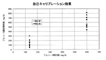
補正前と補正後のグルコース濃度測定値をプロットした自己キャリブレーション測定によるグルコース測定値の補正効果を確認したところ、図5および表1に示すように、補正(自己キャリブレーション)がないデータに比べて同時再現性の向上が確認され、補正効果が高いことが確認された。 When the correction effect of the glucose measurement value by the self-calibration measurement in which the glucose concentration measurement values before and after the correction were plotted was confirmed, as shown in FIG. 5 and Table 1, compared with the data without the correction (self-calibration). It was confirmed that the simultaneous reproducibility was improved and that the correction effect was high.
以上より、酵素の電子伝達部位の還元電流を検出することにより、酸化還元反応および電極との電子授受に寄与しうる酵素量(酵素活性)に起因する補正係数を計算し、この補正係数に基づいて測定対象物質の測定結果を補正する自己キャリブレーションが可能であることが分かった。
すなわち、酸化還元酵素の電子伝達部位である、βサブユニットのヘム由来の還元反応測定により酸化還元反応および電極との電子授受に寄与しうる酵素量(酵素活性)を反映する補正係数を算出する。具体的には、ヘムの酸化還元電位よりネガティブな電位でヘムの還元反応電流を測定しセンサ間差を捉える。これにより、酵素と電極材料の結合状態が把握でき、酸化還元反応および電極との電子授受に寄与しうる酵素量の把握が可能になる。その後、あらかじめ作成した、自己キャリブレーション検量線からの、自己キャリブレーション結果の乖離を計算することにより、補正係数を計算し、これをグルコースの測定結果に乗じることで、個々のセンサ毎の補正が可能になる。また、本自己キャリブレーションの方法は、酵素の酸化還元電位を既知の方法で把握することで、他の基質の測定にも適応が可能である。
さらに、本補正方法は、センサの製造時における製造ロットの評価にも適応できる。つまり、製造ロット内でサンプリングしたセンサについて自己キャリブレーションを実施することにより、センサについて製造ロット毎の平均補正係数数を算出し、ロット補正係数の一部とすることができる。これにより、センサを用いて測定する毎に自己キャリブレーションを実施せずとも、簡易的な測定値の補正が可能になる。
From the above, a correction coefficient due to the amount of enzyme (enzyme activity) that can contribute to the redox reaction and electron transfer with the electrode is calculated by detecting the reduction current at the electron transfer site of the enzyme, and based on this correction coefficient. It was found that self-calibration is possible to correct the measurement result of the substance to be measured.
That is, a correction coefficient that reflects the amount of enzyme (enzyme activity) that can contribute to the redox reaction and electron transfer with the electrode is calculated by measuring the redox reaction from the heme of the β subunit, which is the electron transfer site of the redox enzyme. .. Specifically, the reduction reaction current of heme is measured at a potential more negative than the redox potential of heme, and the difference between the sensors is captured. As a result, the bonding state between the enzyme and the electrode material can be grasped, and the amount of the enzyme that can contribute to the redox reaction and the electron transfer between the electrodes can be grasped. After that, the correction coefficient is calculated by calculating the deviation of the self-calibration result from the self-calibration calibration curve created in advance, and by multiplying this by the glucose measurement result, the correction for each individual sensor is performed. It will be possible. In addition, this self-calibration method can be applied to the measurement of other substrates by grasping the redox potential of the enzyme by a known method.
Further, this correction method can be applied to the evaluation of the production lot at the time of manufacturing the sensor. That is, by performing self-calibration on the sensor sampled in the manufacturing lot, the average number of correction coefficients for each manufacturing lot can be calculated for the sensor and used as a part of the lot correction coefficient. As a result, it is possible to easily correct the measured value without performing self-calibration every time the measurement is performed using the sensor.
1・・・グルコースセンサ
10・・・カバー板
11・・・スペーサー
12・・・基板
13・・・穴部
14・・・スリット
15・・・キャピラリー
16・・・第1
電極
17・・・第2電極
18・・・試薬層
19・・・絶縁膜
2・・・測定装置
20・・・出力部
21・・・電力供給装置
22・・・制御部
23・・・演算部
24・・・検出部
25・・・表示部ユニット
26・・・バッテリ
3・・・制御コンピュータ
3A・・・ポテンショスタット
3a・・・基板
CR、W・・・端子
4・・・グルコースセンサ
1 ...
Claims (10)
第一の電圧を電極系に印加する第一の電圧印加工程と、
第二の電圧を電極系に印加する第二の電圧印加工程と、
前記第一の電圧印加工程において、酸化還元反応および電極との電子授受に寄与しうる前記酸化還元酵素の量に依存する第一のシグナルを取得する工程と、
前記第二の電圧印加工程において、前記試料中の測定対象物質の量に依存する第二のシグナルを取得する工程と、
あらかじめ作成された前記第一のシグナルと前記第二のシグナルの検量線を用い、前記第一のシグナルの測定値の、当該検量線からの乖離度から補正係数を算出し、前記第二のシグナルの測定値を前記補正係数で補正し、補正された第二のシグナルの値に基づいて、試料中の測定対象物質の濃度を決定する工程を含む、バイオセンサを用いた測定方法。 A measurement target in an electrochemical measurement cell including an insulating substrate and an electrode system including two or more electrodes formed on the insulating substrate, wherein at least one electrode contains an oxidoreductase. The process of introducing a sample containing a substance and
The first voltage application step of applying the first voltage to the electrode system and
A second voltage application step of applying a second voltage to the electrode system, and
In the first voltage application step, a step of acquiring a first signal depending on the amount of the oxidoreductase that can contribute to the redox reaction and electron transfer with the electrode, and
In the second voltage application step, a step of acquiring a second signal depending on the amount of the substance to be measured in the sample, and a step of acquiring the second signal.
Using the calibration curve of the first signal and the second signal prepared in advance, the correction coefficient is calculated from the degree of deviation of the measured value of the first signal from the calibration curve, and the second signal. A measurement method using a biosensor, which comprises a step of correcting the measured value of the above with the correction coefficient and determining the concentration of the substance to be measured in the sample based on the corrected value of the second signal .
第二の電圧が、前記酸化還元酵素の酸化電位以上の電圧であることを特徴とする、請求項1に記載の測定方法。 The first voltage is a voltage equal to or lower than the reduction potential of the oxidoreductase.
The measuring method according to claim 1, wherein the second voltage is a voltage equal to or higher than the oxidation potential of the oxidoreductase.
バイオセンサへの第一の電圧印加および第二の電圧印加を制御する、制御部と、
バイオセンサへの第一及び第二の電圧印加により得られる、第一及び第二のシグナルを検出する、検出部と、
あらかじめ作成された前記第一のシグナルと前記第二のシグナルの検量線を用い、前記第一のシグナルの測定値の、当該検量線からの乖離度から補正係数を算出し、前記第二のシグナルの測定値を前記補正係数で補正し、補正された第二のシグナルの値に基づいて試料中に含まれる物質の濃度を決定する、演算部と、
前記算出された前記物質の濃度を出力する出力部とから構成される測定装置。 A biosensor including an electrochemical measurement cell including an insulating substrate and an electrode system including two or more electrodes formed on the insulating substrate, wherein at least one electrode contains an oxidoreductase. When,
A control unit that controls the application of the first voltage and the application of the second voltage to the biosensor.
A detector that detects the first and second signals obtained by applying the first and second voltages to the biosensor, and
Using the calibration curve of the first signal and the second signal prepared in advance, the correction coefficient is calculated from the degree of deviation of the measured value of the first signal from the calibration curve, and the second signal. The calculation unit, which corrects the measured value of the above with the correction coefficient and determines the concentration of the substance contained in the sample based on the corrected value of the second signal .
A measuring device including an output unit that outputs the calculated concentration of the substance.
Applications Claiming Priority (2)
| Application Number | Priority Date | Filing Date | Title |
|---|---|---|---|
| JP2016053071 | 2016-03-16 | ||
| JP2016053071 | 2016-03-16 |
Publications (2)
| Publication Number | Publication Date |
|---|---|
| JP2017173317A JP2017173317A (en) | 2017-09-28 |
| JP6817111B2 true JP6817111B2 (en) | 2021-01-20 |
Family
ID=58387661
Family Applications (1)
| Application Number | Title | Priority Date | Filing Date |
|---|---|---|---|
| JP2017042361A Active JP6817111B2 (en) | 2016-03-16 | 2017-03-07 | Material measurement method and measuring device using electrochemical biosensor |
Country Status (4)
| Country | Link |
|---|---|
| US (1) | US10451577B2 (en) |
| EP (1) | EP3220138B1 (en) |
| JP (1) | JP6817111B2 (en) |
| CN (1) | CN107202826B (en) |
Families Citing this family (7)
| Publication number | Priority date | Publication date | Assignee | Title |
|---|---|---|---|---|
| JP7278147B2 (en) * | 2018-05-22 | 2023-05-19 | アークレイ株式会社 | New biosensing method |
| US10948450B2 (en) * | 2018-07-23 | 2021-03-16 | Genmark Diagnostics, Inc. | Electrochemical measurements of components in coatings |
| CN109270145B (en) * | 2018-11-20 | 2021-09-17 | 三诺生物传感股份有限公司 | Method for testing electrochemical test strip with double electrodes |
| JP6606625B1 (en) * | 2019-09-12 | 2019-11-13 | 株式会社ちとせ研究所 | System for estimating the dynamics of the measurement target system using redox potential |
| KR102346784B1 (en) * | 2020-08-06 | 2022-01-04 | 알사란 자빕 | Biochem Kit and method for measuring biochem information using thereof |
| CN115684317A (en) * | 2022-10-28 | 2023-02-03 | 东莞市源凯电气有限公司 | Purine detection module and method |
| EP4410198A1 (en) | 2023-01-31 | 2024-08-07 | Nutrix Poland Sp. z o.o. | Read-out device and carrier for analyte detection |
Family Cites Families (12)
| Publication number | Priority date | Publication date | Assignee | Title |
|---|---|---|---|---|
| US5128015A (en) | 1988-03-15 | 1992-07-07 | Tall Oak Ventures | Method and apparatus for amperometric diagnostic analysis |
| AU644059B2 (en) | 1988-03-15 | 1993-12-02 | Roche Diagnostics Corporation | Method and apparatus for amperometric diagnostic analysis |
| US5108564A (en) | 1988-03-15 | 1992-04-28 | Tall Oak Ventures | Method and apparatus for amperometric diagnostic analysis |
| USRE36268E (en) | 1988-03-15 | 1999-08-17 | Boehringer Mannheim Corporation | Method and apparatus for amperometric diagnostic analysis |
| US5298144A (en) * | 1992-09-15 | 1994-03-29 | The Yellow Springs Instrument Company, Inc. | Chemically wired fructose dehydrogenase electrodes |
| JP3655587B2 (en) * | 1999-09-20 | 2005-06-02 | ロシュ ダイアグノスティックス コーポレーション | Small biosensor for continuous analyte monitoring |
| US7045054B1 (en) * | 1999-09-20 | 2006-05-16 | Roche Diagnostics Corporation | Small volume biosensor for continuous analyte monitoring |
| WO2005030807A1 (en) | 2003-09-30 | 2005-04-07 | Koji Sode | Glucose dehydrogenase/cytochrome fused protein |
| ES2716136T3 (en) * | 2005-09-30 | 2019-06-10 | Ascensia Diabetes Care Holdings Ag | Controlled voltammetry |
| WO2014002999A1 (en) * | 2012-06-25 | 2014-01-03 | 合同会社バイオエンジニアリング研究所 | Enzyme electrode |
| KR101732300B1 (en) * | 2013-03-15 | 2017-05-02 | 에프. 호프만-라 로슈 아게 | Methods of failsafing electrochemical measurements of an analyte as well as devices, apparatuses and systems incorporating the same |
| WO2015020149A1 (en) * | 2013-08-07 | 2015-02-12 | アークレイ株式会社 | Substance measurement method and measurement device employing electrochemical biosensor |
-
2017
- 2017-03-07 JP JP2017042361A patent/JP6817111B2/en active Active
- 2017-03-10 CN CN201710141172.4A patent/CN107202826B/en active Active
- 2017-03-14 US US15/458,902 patent/US10451577B2/en active Active
- 2017-03-16 EP EP17161299.7A patent/EP3220138B1/en active Active
Also Published As
| Publication number | Publication date |
|---|---|
| US20170269022A1 (en) | 2017-09-21 |
| JP2017173317A (en) | 2017-09-28 |
| CN107202826A (en) | 2017-09-26 |
| EP3220138B1 (en) | 2019-02-27 |
| CN107202826B (en) | 2020-09-18 |
| EP3220138A1 (en) | 2017-09-20 |
| US10451577B2 (en) | 2019-10-22 |
Similar Documents
| Publication | Publication Date | Title |
|---|---|---|
| JP6817111B2 (en) | Material measurement method and measuring device using electrochemical biosensor | |
| JP6435264B2 (en) | Method and apparatus for measuring substances using electrochemical biosensor | |
| US20200271619A1 (en) | Devices using gated voltammetry methods | |
| JP5745835B2 (en) | Filling sufficiency method and system | |
| US20170138886A1 (en) | Analyte Sensors and Methods of Using Same | |
| JPWO2008047842A1 (en) | Method for measuring hematocrit value of blood sample, method for measuring concentration of analyte in blood sample, sensor chip and sensor unit | |
| CN110514704B (en) | Novel biosensing method | |
| JP6607437B2 (en) | Biosensor | |
| TW201719161A (en) | System and method for compensating sample-related measurements based on polarization effects of test strips | |
| US9080248B2 (en) | Method for forming a test sensor | |
| CN115280141A (en) | Electrochemical sensor and method for manufacturing the same | |
| US10788441B2 (en) | Measuring method of sensor using interdigitated array electrode, measuring apparatus and computer readable medium storing measuring program | |
| US11073495B2 (en) | Biosensor and manufacturing method of biosensor | |
| KR20220098525A (en) | Biosensor | |
| WO2015178912A1 (en) | Analyte sensors and methods of using same | |
| JP2020067350A (en) | Biosensor and method for measuring amount of blood component using the same | |
| JP2019168363A (en) | Measuring method and measuring device |
Legal Events
| Date | Code | Title | Description |
|---|---|---|---|
| A621 | Written request for application examination |
Free format text: JAPANESE INTERMEDIATE CODE: A621 Effective date: 20191004 |
|
| A977 | Report on retrieval |
Free format text: JAPANESE INTERMEDIATE CODE: A971007 Effective date: 20200821 |
|
| A131 | Notification of reasons for refusal |
Free format text: JAPANESE INTERMEDIATE CODE: A131 Effective date: 20200929 |
|
| A521 | Request for written amendment filed |
Free format text: JAPANESE INTERMEDIATE CODE: A523 Effective date: 20201111 |
|
| TRDD | Decision of grant or rejection written | ||
| A01 | Written decision to grant a patent or to grant a registration (utility model) |
Free format text: JAPANESE INTERMEDIATE CODE: A01 Effective date: 20201208 |
|
| A61 | First payment of annual fees (during grant procedure) |
Free format text: JAPANESE INTERMEDIATE CODE: A61 Effective date: 20201224 |
|
| R150 | Certificate of patent or registration of utility model |
Ref document number: 6817111 Country of ref document: JP Free format text: JAPANESE INTERMEDIATE CODE: R150 |
|
| R250 | Receipt of annual fees |
Free format text: JAPANESE INTERMEDIATE CODE: R250 |