JP6813494B2 - Coherent single-layer high-strength synthetic polymer composite for prosthetic valves - Google Patents
Coherent single-layer high-strength synthetic polymer composite for prosthetic valves Download PDFInfo
- Publication number
- JP6813494B2 JP6813494B2 JP2017542435A JP2017542435A JP6813494B2 JP 6813494 B2 JP6813494 B2 JP 6813494B2 JP 2017542435 A JP2017542435 A JP 2017542435A JP 2017542435 A JP2017542435 A JP 2017542435A JP 6813494 B2 JP6813494 B2 JP 6813494B2
- Authority
- JP
- Japan
- Prior art keywords
- fibers
- leaflet
- single layer
- less
- coherent single
- Prior art date
- Legal status (The legal status is an assumption and is not a legal conclusion. Google has not performed a legal analysis and makes no representation as to the accuracy of the status listed.)
- Active
Links
- GMLWLVOXJVWGOO-UHFFFAOYSA-N CC(CC1)C2=C1C1C2C(C)C2C1C2 Chemical compound CC(CC1)C2=C1C1C2C(C)C2C1C2 GMLWLVOXJVWGOO-UHFFFAOYSA-N 0.000 description 1
Images


Classifications
-
- A—HUMAN NECESSITIES
- A61—MEDICAL OR VETERINARY SCIENCE; HYGIENE
- A61L—METHODS OR APPARATUS FOR STERILISING MATERIALS OR OBJECTS IN GENERAL; DISINFECTION, STERILISATION OR DEODORISATION OF AIR; CHEMICAL ASPECTS OF BANDAGES, DRESSINGS, ABSORBENT PADS OR SURGICAL ARTICLES; MATERIALS FOR BANDAGES, DRESSINGS, ABSORBENT PADS OR SURGICAL ARTICLES
- A61L27/00—Materials for grafts or prostheses or for coating grafts or prostheses
- A61L27/14—Macromolecular materials
- A61L27/16—Macromolecular materials obtained by reactions only involving carbon-to-carbon unsaturated bonds
-
- A—HUMAN NECESSITIES
- A61—MEDICAL OR VETERINARY SCIENCE; HYGIENE
- A61F—FILTERS IMPLANTABLE INTO BLOOD VESSELS; PROSTHESES; DEVICES PROVIDING PATENCY TO, OR PREVENTING COLLAPSING OF, TUBULAR STRUCTURES OF THE BODY, e.g. STENTS; ORTHOPAEDIC, NURSING OR CONTRACEPTIVE DEVICES; FOMENTATION; TREATMENT OR PROTECTION OF EYES OR EARS; BANDAGES, DRESSINGS OR ABSORBENT PADS; FIRST-AID KITS
- A61F2/00—Filters implantable into blood vessels; Prostheses, i.e. artificial substitutes or replacements for parts of the body; Appliances for connecting them with the body; Devices providing patency to, or preventing collapsing of, tubular structures of the body, e.g. stents
- A61F2/02—Prostheses implantable into the body
- A61F2/24—Heart valves ; Vascular valves, e.g. venous valves; Heart implants, e.g. passive devices for improving the function of the native valve or the heart muscle; Transmyocardial revascularisation [TMR] devices; Valves implantable in the body
- A61F2/2412—Heart valves ; Vascular valves, e.g. venous valves; Heart implants, e.g. passive devices for improving the function of the native valve or the heart muscle; Transmyocardial revascularisation [TMR] devices; Valves implantable in the body with soft flexible valve members, e.g. tissue valves shaped like natural valves
- A61F2/2415—Manufacturing methods
-
- A—HUMAN NECESSITIES
- A61—MEDICAL OR VETERINARY SCIENCE; HYGIENE
- A61F—FILTERS IMPLANTABLE INTO BLOOD VESSELS; PROSTHESES; DEVICES PROVIDING PATENCY TO, OR PREVENTING COLLAPSING OF, TUBULAR STRUCTURES OF THE BODY, e.g. STENTS; ORTHOPAEDIC, NURSING OR CONTRACEPTIVE DEVICES; FOMENTATION; TREATMENT OR PROTECTION OF EYES OR EARS; BANDAGES, DRESSINGS OR ABSORBENT PADS; FIRST-AID KITS
- A61F2/00—Filters implantable into blood vessels; Prostheses, i.e. artificial substitutes or replacements for parts of the body; Appliances for connecting them with the body; Devices providing patency to, or preventing collapsing of, tubular structures of the body, e.g. stents
- A61F2/02—Prostheses implantable into the body
- A61F2/24—Heart valves ; Vascular valves, e.g. venous valves; Heart implants, e.g. passive devices for improving the function of the native valve or the heart muscle; Transmyocardial revascularisation [TMR] devices; Valves implantable in the body
- A61F2/2412—Heart valves ; Vascular valves, e.g. venous valves; Heart implants, e.g. passive devices for improving the function of the native valve or the heart muscle; Transmyocardial revascularisation [TMR] devices; Valves implantable in the body with soft flexible valve members, e.g. tissue valves shaped like natural valves
- A61F2/2418—Scaffolds therefor, e.g. support stents
-
- A—HUMAN NECESSITIES
- A61—MEDICAL OR VETERINARY SCIENCE; HYGIENE
- A61L—METHODS OR APPARATUS FOR STERILISING MATERIALS OR OBJECTS IN GENERAL; DISINFECTION, STERILISATION OR DEODORISATION OF AIR; CHEMICAL ASPECTS OF BANDAGES, DRESSINGS, ABSORBENT PADS OR SURGICAL ARTICLES; MATERIALS FOR BANDAGES, DRESSINGS, ABSORBENT PADS OR SURGICAL ARTICLES
- A61L27/00—Materials for grafts or prostheses or for coating grafts or prostheses
- A61L27/14—Macromolecular materials
- A61L27/18—Macromolecular materials obtained otherwise than by reactions only involving carbon-to-carbon unsaturated bonds
-
- A—HUMAN NECESSITIES
- A61—MEDICAL OR VETERINARY SCIENCE; HYGIENE
- A61L—METHODS OR APPARATUS FOR STERILISING MATERIALS OR OBJECTS IN GENERAL; DISINFECTION, STERILISATION OR DEODORISATION OF AIR; CHEMICAL ASPECTS OF BANDAGES, DRESSINGS, ABSORBENT PADS OR SURGICAL ARTICLES; MATERIALS FOR BANDAGES, DRESSINGS, ABSORBENT PADS OR SURGICAL ARTICLES
- A61L27/00—Materials for grafts or prostheses or for coating grafts or prostheses
- A61L27/50—Materials characterised by their function or physical properties, e.g. injectable or lubricating compositions, shape-memory materials, surface modified materials
- A61L27/507—Materials characterised by their function or physical properties, e.g. injectable or lubricating compositions, shape-memory materials, surface modified materials for artificial blood vessels
-
- A—HUMAN NECESSITIES
- A61—MEDICAL OR VETERINARY SCIENCE; HYGIENE
- A61L—METHODS OR APPARATUS FOR STERILISING MATERIALS OR OBJECTS IN GENERAL; DISINFECTION, STERILISATION OR DEODORISATION OF AIR; CHEMICAL ASPECTS OF BANDAGES, DRESSINGS, ABSORBENT PADS OR SURGICAL ARTICLES; MATERIALS FOR BANDAGES, DRESSINGS, ABSORBENT PADS OR SURGICAL ARTICLES
- A61L27/00—Materials for grafts or prostheses or for coating grafts or prostheses
- A61L27/50—Materials characterised by their function or physical properties, e.g. injectable or lubricating compositions, shape-memory materials, surface modified materials
- A61L27/56—Porous materials, e.g. foams or sponges
-
- A—HUMAN NECESSITIES
- A61—MEDICAL OR VETERINARY SCIENCE; HYGIENE
- A61F—FILTERS IMPLANTABLE INTO BLOOD VESSELS; PROSTHESES; DEVICES PROVIDING PATENCY TO, OR PREVENTING COLLAPSING OF, TUBULAR STRUCTURES OF THE BODY, e.g. STENTS; ORTHOPAEDIC, NURSING OR CONTRACEPTIVE DEVICES; FOMENTATION; TREATMENT OR PROTECTION OF EYES OR EARS; BANDAGES, DRESSINGS OR ABSORBENT PADS; FIRST-AID KITS
- A61F2/00—Filters implantable into blood vessels; Prostheses, i.e. artificial substitutes or replacements for parts of the body; Appliances for connecting them with the body; Devices providing patency to, or preventing collapsing of, tubular structures of the body, e.g. stents
- A61F2/02—Prostheses implantable into the body
- A61F2/24—Heart valves ; Vascular valves, e.g. venous valves; Heart implants, e.g. passive devices for improving the function of the native valve or the heart muscle; Transmyocardial revascularisation [TMR] devices; Valves implantable in the body
- A61F2/2427—Devices for manipulating or deploying heart valves during implantation
- A61F2/243—Deployment by mechanical expansion
- A61F2/2433—Deployment by mechanical expansion using balloon catheter
-
- A—HUMAN NECESSITIES
- A61—MEDICAL OR VETERINARY SCIENCE; HYGIENE
- A61F—FILTERS IMPLANTABLE INTO BLOOD VESSELS; PROSTHESES; DEVICES PROVIDING PATENCY TO, OR PREVENTING COLLAPSING OF, TUBULAR STRUCTURES OF THE BODY, e.g. STENTS; ORTHOPAEDIC, NURSING OR CONTRACEPTIVE DEVICES; FOMENTATION; TREATMENT OR PROTECTION OF EYES OR EARS; BANDAGES, DRESSINGS OR ABSORBENT PADS; FIRST-AID KITS
- A61F2210/00—Particular material properties of prostheses classified in groups A61F2/00 - A61F2/26 or A61F2/82 or A61F9/00 or A61F11/00 or subgroups thereof
- A61F2210/0076—Particular material properties of prostheses classified in groups A61F2/00 - A61F2/26 or A61F2/82 or A61F9/00 or A61F11/00 or subgroups thereof multilayered, e.g. laminated structures
-
- A—HUMAN NECESSITIES
- A61—MEDICAL OR VETERINARY SCIENCE; HYGIENE
- A61L—METHODS OR APPARATUS FOR STERILISING MATERIALS OR OBJECTS IN GENERAL; DISINFECTION, STERILISATION OR DEODORISATION OF AIR; CHEMICAL ASPECTS OF BANDAGES, DRESSINGS, ABSORBENT PADS OR SURGICAL ARTICLES; MATERIALS FOR BANDAGES, DRESSINGS, ABSORBENT PADS OR SURGICAL ARTICLES
- A61L2430/00—Materials or treatment for tissue regeneration
- A61L2430/20—Materials or treatment for tissue regeneration for reconstruction of the heart, e.g. heart valves
Description
本発明は医療用インプラントで使用される材料に関する。より具体的には、本発明は、人工心臓弁を含めた高サイクルでの屈曲が生じる用途での使用に好適な生体適合性材料に関する。 The present invention relates to materials used in medical implants. More specifically, the present invention relates to biocompatible materials suitable for use in applications where flexion occurs at high cycles, including artificial heart valves.
人工心臓弁は、生体内で少なくとも10年使用できることが好ましい。人工心臓弁は、そのような長期にわたって使用するには、少なくとも4億回以上のサイクルという十分な耐久性を示さねばならない。弁、より具体的には心臓弁リーフレットは、穴や破れの形成といった構造上の劣化に加え、石灰化や血栓形成といった生物学的な悪影響に抵抗せねばならない。 The artificial heart valve is preferably usable in vivo for at least 10 years. Artificial heart valves must exhibit sufficient durability with at least 400 million cycles for such long-term use. Valves, and more specifically heart valve leaflets, must resist structural degradation such as the formation of holes and tears, as well as the biological adverse effects of calcification and thrombus formation.
これまで、さまざまなポリマー材料が人工心臓弁リーフレットとして使用されてきた。硬直化と穴の形成が原因となるリーフレットの故障が、埋め込み後2年以内に起こっていた。リーフレットを厚くして耐久性を改善する努力の結果、弁の血行力学的性能は許容できない、すなわち開いた弁を通る際の圧力の低下が高すぎるようになっていた。 So far, various polymeric materials have been used as artificial heart valve leaflets. Leaflet failures due to rigidity and hole formation occurred within two years of implantation. As a result of efforts to thicken the leaflet to improve durability, the hemodynamic performance of the valve was unacceptable, i.e. the pressure drop as it passed through the open valve became too high.
そのため、少なくとも約4億回以上繰り返して屈曲させるのに十分な耐久性を示すことで、生体内において10年を超えて使用できるよう設計された生体適合性のある人工心臓弁を提供することが依然として望まれている。 Therefore, it is possible to provide a biocompatible artificial heart valve designed to be used in vivo for more than 10 years by showing sufficient durability to repeatedly bend at least about 400 million times. Still desired.
層間剥離は、合成人工心臓弁リーフレットに潜在的な懸念事項である。心臓サイクルの間、心臓弁リーフレットは、曲げによる様々な応力を受ける。リーフレットの特定の部分が曲げに曝され、その部分がリーフレットに裂け目や空隙を生じさせることがある。リーフレットの層間剥離により、生体内環境でのリーフレットが破損してしまう可能性がある。リーフレットが層間剥離すると、空間が生じ、そこに血液成分が浸透する可能性がある。流体のしぶき、または血栓が、リーフレットの動きに影響を与え、これにより、石灰化し、弁機能への影響を与え、最終的には弁の早期故障を招く可能性がある。 Delamination is a potential concern for synthetic heart valve leaflets. During the cardiac cycle, the heart valve leaflets are subject to various stresses due to bending. Certain parts of the leaflet are exposed to bending, which can create crevices and voids in the leaflet. Delamination of the leaflet may damage the leaflet in the in vivo environment. Delamination of the leaflet creates a space in which blood components can penetrate. Splashes of fluid, or blood clots, can affect leaflet movement, which can lead to calcification, impact on valve function, and ultimately premature valve failure.
当該技術分野では、合成心臓弁リーフレットの層間剥離耐性を改善する手段に対する必要性が継続的に存在する。 In the art, there is an ongoing need for means to improve the delamination resistance of synthetic heart valve leaflets.
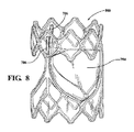
1つの一般的な態様は、フレーム、及び、該フレームに連結され、かつ開放位置と閉鎖位置との間を移動可能であり、少なくとも1つのコヒーレントシングルレイヤおよびエラストマーを備えるリーフレットを備える人工弁であって、コヒーレントシングルレイヤは、細孔を有しかつ合成ポリマーであって、エラストマーは、コヒーレントシングルレイヤが不浸透性であるように細孔内に存在する、人工弁を含む。実施形態として、以下の1つまたは複数の特徴を含んでもよい。唯一のコヒーレントシングルレイヤを備える人工弁。少なくとも1つのコヒーレントシングルレイヤは、1層の多孔性合成ポリマー膜である、人工弁。少なくとも1つのコヒーレントシングルレイヤは繊維を含み、該繊維はそれらの間の空間を画定し、該繊維の大部分の直径は1.0μm未満であり、前記繊維間の空間は、孔径が約5μm未満である細孔を画定し、リーフレットは、少なくとも2つの直交した方向に約35 MPa超の引張強度を有する、人工弁。少なくとも1つのコヒーレントシングルレイヤは繊維を含み、該繊維はそれらの間の空間を画定し、該繊維の大部分の直径は1.0μm未満であり、前記繊維間の空間は、孔径が約5μm未満である細孔を画定し、リーフレットは、約1 N/mm超の破断荷重を有する、人工弁。少なくとも1つのコヒーレントシングルレイヤは繊維を含み、該繊維はそれらの間の空間を画定し、該繊維の大部分の直径は1.0μm未満であり、前記繊維間の空間は、孔径が約5μm未満である細孔を画定し、リーフレットは圧縮曲げ試験に合格している、人工弁。少なくとも1つのコヒーレントシングルレイヤは繊維を含み、該繊維はそれらの間の空間を画定し、該繊維の大部分の直径は1.0μm未満であり、前記繊維間の空間は、孔径が約5μm未満である細孔を画定し、リーフレットは15%未満の圧縮永久ひずみを有する、人工弁。少なくとも1つのコヒーレントシングルレイヤは繊維を含み、該繊維はそれらの間の空間を画定し、該繊維の大部分の直径は1.0μm未満であり、前記繊維間の空間は、孔径が約5μm未満である細孔を画定し、リーフレットは、10%未満の液体ピックアップ値を有する、人工弁。少なくとも1つのコヒーレントシングルレイヤは繊維を含み、該繊維はそれらの間の空間を画定し、該繊維の大部分の直径は1.0μm未満であり、前記繊維間の空間は、孔径が約5μm未満である細孔を画定し、リーフレットは、2つの直交した方向における引張強度の比が2未満を示す、人工弁。少なくとも1つのコヒーレントシングルレイヤは、複数層の多孔性合成ポリマー膜を含み、前記複数層は追加の材料を使用することなく一緒に接合される、人工弁。少なくとも1つのコヒーレントシングルレイヤは繊維を含み、該繊維はそれらの間の空間を画定し、該繊維の大部分の直径は1.0μm未満であり、前記繊維間の空間は、孔径が約5μm未満である細孔を画定し、リーフレットは、少なくとも2つの直交した方向に約35 MPa超の引張強度を有する、人工弁。少なくとも1つのコヒーレントシングルレイヤは繊維を含み、該繊維はそれらの間の空間を画定し、該繊維の大部分の直径は1.0μm未満であり、前記繊維間の空間は、孔径が約5μm未満である細孔を画定し、リーフレットは、約1 N/mm超の破断荷重を有する、人工弁。少なくとも1つのコヒーレントシングルレイヤは繊維を含み、該繊維はそれらの間の空間を画定し、該繊維の大部分の直径は1.0μm未満であり、前記繊維間の空間は、孔径が約5μm未満である細孔を画定し、リーフレットは圧縮曲げ試験に合格している、人工弁。少なくとも1つのコヒーレントシングルレイヤは繊維を含み、該繊維はそれらの間の空間を画定し、該繊維の大部分の直径は1.0μm未満であり、前記繊維間の空間は、孔径が約5μm未満である細孔を画定し、リーフレットは15%未満の圧縮永久ひずみを有する、人工弁。少なくとも1つのコヒーレントシングルレイヤは繊維を含み、該繊維はそれらの間の空間を画定し、該繊維の大部分の直径は1.0μm未満であり、前記繊維間の空間は、孔径が約5μm未満である細孔を画定し、リーフレットは、10%未満の液体ピックアップ値を有する、人工弁。少なくとも1つのコヒーレントシングルレイヤは繊維を含み、該繊維はそれらの間の空間を画定し、該繊維の大部分の直径は1.0μm未満であり、前記繊維間の空間は、孔径が約5μm未満である細孔を画定し、リーフレットは、2つの直交した方向における引張強度の比が2未満を示す、人工弁。少なくとも1つのコヒーレントシングルレイヤは、それらの間にあるエラストマーにより一緒に結合された複数のコヒーレントシングルレイヤである、人工弁。唯一のコヒーレントシングルレイヤを備える人工弁。少なくとも1つのコヒーレントシングルレイヤは、1層の多孔性合成ポリマー膜である、人工弁。少なくとも1つのコヒーレントシングルレイヤは繊維を含み、該繊維はそれらの間の空間を画定し、該繊維の大部分の直径は1.0μm未満であり、前記繊維間の空間は、孔径が約5μm未満である細孔を画定し、リーフレットは、少なくとも2つの直交した方向に約35 MPa超の引張強度を有する、人工弁。少なくとも1つのコヒーレントシングルレイヤは繊維を含み、該繊維はそれらの間の空間を画定し、該繊維の大部分の直径は1.0μm未満であり、前記繊維間の空間は、孔径が約5μm未満である細孔を画定し、リーフレットは、約1 N/mm超の破断荷重を有する、人工弁。少なくとも1つのコヒーレントシングルレイヤは繊維を含み、該繊維はそれらの間の空間を画定し、該繊維の大部分の直径は1.0μm未満であり、前記繊維間の空間は、孔径が約5μm未満である細孔を画定し、リーフレットは圧縮曲げ試験に合格している、人工弁。少なくとも1つのコヒーレントシングルレイヤは繊維を含み、該繊維はそれらの間の空間を画定し、該繊維の大部分の直径は1.0μm未満であり、前記繊維間の空間は、孔径が約5μm未満である細孔を画定し、リーフレットは15%未満の圧縮永久ひずみを有する、人工弁。少なくとも1つのコヒーレントシングルレイヤは繊維を含み、該繊維はそれらの間の空間を画定し、該繊維の大部分の直径は1.0μm未満であり、前記繊維間の空間は、孔径が約5μm未満である細孔を画定し、リーフレットは、10%未満の液体ピックアップ値を有する、人工弁。少なくとも1つのコヒーレントシングルレイヤは繊維を含み、該繊維はそれらの間の空間を画定し、該繊維の大部分の直径は1.0μm未満であり、前記繊維間の空間は、孔径が約5μm未満である細孔を画定し、リーフレットは、2つの直交した方向における引張強度の比が2未満を示す、人工弁。少なくとも1つのコヒーレントシングルレイヤは、複数層の多孔性合成ポリマー膜を含み、前記複数層は追加の材料を使用することなく一緒に接合される、人工弁。少なくとも1つのコヒーレントシングルレイヤは繊維を含み、該繊維はそれらの間の空間を画定し、該繊維の大部分の直径は1.0μm未満であり、前記繊維間の空間は、孔径が約5μm未満である細孔を画定し、リーフレットは、少なくとも2つの直交した方向に約35 MPa超の引張強度を有する、人工弁。少なくとも1つのコヒーレントシングルレイヤは繊維を含み、該繊維はそれらの間の空間を画定し、該繊維の大部分の直径は1.0μm未満であり、前記繊維間の空間は、孔径が約5μm未満である細孔を画定し、リーフレットは、約1 N/mm超の破断荷重を有する、人工弁。少なくとも1つのコヒーレントシングルレイヤは繊維を含み、該繊維はそれらの間の空間を画定し、該繊維の大部分の直径は1.0μm未満であり、前記繊維間の空間は、孔径が約5μm未満である細孔を画定し、リーフレットは圧縮曲げ試験に合格している、人工弁。少なくとも1つのコヒーレントシングルレイヤは繊維を含み、該繊維はそれらの間の空間を画定し、該繊維の大部分の直径は1.0μm未満であり、前記繊維間の空間は、孔径が約5μm未満である細孔を画定し、リーフレットは15%未満の圧縮永久ひずみを有する、人工弁。少なくとも1つのコヒーレントシングルレイヤは繊維を含み、該繊維はそれらの間の空間を画定し、該繊維の大部分の直径は1.0μm未満であり、前記繊維間の空間は、孔径が約5μm未満である細孔を画定し、リーフレットは、10%未満の液体ピックアップ値を有する、人工弁。少なくとも1つのコヒーレントシングルレイヤは繊維を含み、該繊維はそれらの間の空間を画定し、該繊維の大部分の直径は1.0μm未満であり、前記繊維間の空間は、孔径が約5μm未満である細孔を画定し、リーフレットは、2つの直交した方向における引張強度の比が2未満を示す、人工弁。少なくとも1つのコヒーレントシングルレイヤは、それらの間にあるエラストマーにより一緒に結合された複数のコヒーレントシングルレイヤである、人工弁。唯一のコヒーレントシングルレイヤを備える人工弁。少なくとも1つのコヒーレントシングルレイヤは繊維を含み、該繊維はそれらの間の空間を画定し、該繊維の大部分の直径は1.0μm未満であり、前記繊維間の空間は、孔径が約5μm未満である細孔を画定し、リーフレットは、少なくとも2つの直交した方向に約35 MPa超の引張強度を有する、人工弁。少なくとも1つのコヒーレントシングルレイヤは繊維を含み、該繊維はそれらの間の空間を画定し、該繊維の大部分の直径は1.0μm未満であり、前記繊維間の空間は、孔径が約5μm未満である細孔を画定し、リーフレットは、約1 N/mm超の破断荷重を有する、人工弁。少なくとも1つのコヒーレントシングルレイヤは繊維を含み、該繊維はそれらの間の空間を画定し、該繊維の大部分の直径は1.0μm未満であり、前記繊維間の空間は、孔径が約5μm未満である細孔を画定し、リーフレットは圧縮曲げ試験に合格している、人工弁。少なくとも1つのコヒーレントシングルレイヤは繊維を含み、該繊維はそれらの間の空間を画定し、該繊維の大部分の直径は1.0μm未満であり、前記繊維間の空間は、孔径が約5μm未満である細孔を画定し、リーフレットは15%未満の圧縮永久ひずみを有する、人工弁。少なくとも1つのコヒーレントシングルレイヤは繊維を含み、該繊維はそれらの間の空間を画定し、該繊維の大部分の直径は1.0μm未満であり、前記繊維間の空間は、孔径が約5μm未満である細孔を画定し、リーフレットは、10%未満の液体ピックアップ値を有する、人工弁。少なくとも1つのコヒーレントシングルレイヤは繊維を含み、該繊維はそれらの間の空間を画定し、該繊維の大部分の直径は1.0μm未満であり、前記繊維間の空間は、孔径が約5μm未満である細孔を画定し、リーフレットは、波長550nmにおける光透過率が60%超である、人工弁。少なくとも1つのコヒーレントシングルレイヤは繊維を含み、該繊維はそれらの間の空間を画定し、該繊維の大部分の直径は1.0μm未満であり、前記繊維間の空間は、孔径が約5μm未満である細孔を画定し、リーフレットは、2つの直交した方向における引張強度の比が2未満を示す、人工弁。リーフレットは、2つの直交した方向における引張強度の比が2未満を示す、人工弁。 One common aspect is a frame and an artificial valve with a leaflet that is connected to the frame and is movable between open and closed positions and has at least one coherent single layer and elastomer. The coherent single layer is a synthetic polymer with pores, and the elastomer comprises an artificial valve that is present in the pores such that the coherent single layer is impermeable. Embodiments may include one or more of the following features: An artificial valve with the only coherent single layer. At least one coherent single layer is an artificial valve, which is a single layer of porous synthetic polymer membrane. At least one coherent single layer contains fibers, the fibers defining the space between them, most of the fibers having a diameter of less than 1.0 μm, and the space between the fibers having a pore size of less than about 5 μm. An artificial valve that defines a pore and the leaflet has a tensile strength of more than about 35 MPa in at least two orthogonal directions. At least one coherent single layer comprises fibers, the fibers defining the space between them, most of the fibers having a diameter of less than 1.0 μm, and the space between the fibers having a pore size of less than about 5 μm. An artificial valve that defines certain pores and the leaflet has a breaking load of more than about 1 N / mm. At least one coherent single layer contains fibers, the fibers defining the space between them, most of the fibers having a diameter of less than 1.0 μm, and the space between the fibers having a pore size of less than about 5 μm. An artificial valve that defines certain pores and the leaflet has passed a compression bending test. At least one coherent single layer comprises fibers, the fibers defining a space between them, most of the fibers having a diameter of less than 1.0 μm, and the space between the fibers having a pore diameter of less than about 5 μm. An artificial valve that defines certain pores and the leaflet has a compression set of less than 15%. At least one coherent single layer contains fibers, the fibers defining the space between them, most of the fibers having a diameter of less than 1.0 μm, and the space between the fibers having a pore size of less than about 5 μm. An artificial valve that defines certain pores and the leaflet has a liquid pickup value of less than 10%. At least one coherent single layer comprises fibers, the fibers defining the space between them, most of the fibers having a diameter of less than 1.0 μm, and the space between the fibers having a pore size of less than about 5 μm. An artificial valve that defines a pore and the leaflet exhibits a ratio of tensile strength in two orthogonal directions of less than 2. An artificial valve in which at least one coherent single layer comprises multiple layers of porous synthetic polymer membranes, the multiple layers being joined together without the use of additional materials. At least one coherent single layer contains fibers, the fibers defining the space between them, most of the fibers having a diameter of less than 1.0 μm, and the space between the fibers having a pore size of less than about 5 μm. An artificial valve that defines a pore and the leaflet has a tensile strength of more than about 35 MPa in at least two orthogonal directions. At least one coherent single layer comprises fibers, the fibers defining the space between them, most of the fibers having a diameter of less than 1.0 μm, and the space between the fibers having a pore size of less than about 5 μm. An artificial valve that defines certain pores and the leaflet has a breaking load of more than about 1 N / mm. At least one coherent single layer contains fibers, the fibers defining the space between them, most of the fibers having a diameter of less than 1.0 μm, and the space between the fibers having a pore size of less than about 5 μm. An artificial valve that defines certain pores and the leaflet has passed a compression bending test. At least one coherent single layer comprises fibers, the fibers defining a space between them, most of the fibers having a diameter of less than 1.0 μm, and the space between the fibers having a pore diameter of less than about 5 μm. An artificial valve that defines certain pores and the leaflet has a compression set of less than 15%. At least one coherent single layer contains fibers, the fibers defining the space between them, most of the fibers having a diameter of less than 1.0 μm, and the space between the fibers having a pore size of less than about 5 μm. An artificial valve that defines certain pores and the leaflet has a liquid pickup value of less than 10%. At least one coherent single layer comprises fibers, the fibers defining the space between them, most of the fibers having a diameter of less than 1.0 μm, and the space between the fibers having a pore size of less than about 5 μm. An artificial valve that defines a pore and the leaflet exhibits a ratio of tensile strength in two orthogonal directions of less than 2. An artificial valve in which at least one coherent single layer is a plurality of coherent single layers bonded together by an elastomer between them. An artificial valve with the only coherent single layer. At least one coherent single layer is an artificial valve, which is a single layer of porous synthetic polymer membrane. At least one coherent single layer contains fibers, the fibers defining the space between them, most of the fibers having a diameter of less than 1.0 μm, and the space between the fibers having a pore size of less than about 5 μm. An artificial valve that defines a pore and the leaflet has a tensile strength of more than about 35 MPa in at least two orthogonal directions. At least one coherent single layer comprises fibers, the fibers defining the space between them, most of the fibers having a diameter of less than 1.0 μm, and the space between the fibers having a pore size of less than about 5 μm. An artificial valve that defines certain pores and the leaflet has a breaking load of more than about 1 N / mm. At least one coherent single layer contains fibers, the fibers defining the space between them, most of the fibers having a diameter of less than 1.0 μm, and the space between the fibers having a pore size of less than about 5 μm. An artificial valve that defines certain pores and the leaflet has passed a compression bending test. At least one coherent single layer comprises fibers, the fibers defining a space between them, most of the fibers having a diameter of less than 1.0 μm, and the space between the fibers having a pore diameter of less than about 5 μm. An artificial valve that defines certain pores and the leaflet has a compression set of less than 15%. At least one coherent single layer contains fibers, the fibers defining the space between them, most of the fibers having a diameter of less than 1.0 μm, and the space between the fibers having a pore size of less than about 5 μm. An artificial valve that defines certain pores and the leaflet has a liquid pickup value of less than 10%. At least one coherent single layer comprises fibers, the fibers defining the space between them, most of the fibers having a diameter of less than 1.0 μm, and the space between the fibers having a pore size of less than about 5 μm. An artificial valve that defines a pore and the leaflet exhibits a ratio of tensile strength in two orthogonal directions of less than 2. An artificial valve in which at least one coherent single layer comprises multiple layers of porous synthetic polymer membranes, the multiple layers being joined together without the use of additional materials. At least one coherent single layer contains fibers, the fibers defining the space between them, most of the fibers having a diameter of less than 1.0 μm, and the space between the fibers having a pore size of less than about 5 μm. An artificial valve that defines a pore and the leaflet has a tensile strength of more than about 35 MPa in at least two orthogonal directions. At least one coherent single layer comprises fibers, the fibers defining the space between them, most of the fibers having a diameter of less than 1.0 μm, and the space between the fibers having a pore size of less than about 5 μm. An artificial valve that defines certain pores and the leaflet has a breaking load of more than about 1 N / mm. At least one coherent single layer contains fibers, the fibers defining the space between them, most of the fibers having a diameter of less than 1.0 μm, and the space between the fibers having a pore size of less than about 5 μm. An artificial valve that defines certain pores and the leaflet has passed a compression bending test. At least one coherent single layer comprises fibers, the fibers defining a space between them, most of the fibers having a diameter of less than 1.0 μm, and the space between the fibers having a pore diameter of less than about 5 μm. An artificial valve that defines certain pores and the leaflet has a compression set of less than 15%. At least one coherent single layer contains fibers, the fibers defining the space between them, most of the fibers having a diameter of less than 1.0 μm, and the space between the fibers having a pore size of less than about 5 μm. An artificial valve that defines certain pores and the leaflet has a liquid pickup value of less than 10%. At least one coherent single layer comprises fibers, the fibers defining the space between them, most of the fibers having a diameter of less than 1.0 μm, and the space between the fibers having a pore size of less than about 5 μm. An artificial valve that defines a pore and the leaflet exhibits a ratio of tensile strength in two orthogonal directions of less than 2. An artificial valve in which at least one coherent single layer is a plurality of coherent single layers bonded together by an elastomer between them. An artificial valve with the only coherent single layer. At least one coherent single layer contains fibers, the fibers defining the space between them, most of the fibers having a diameter of less than 1.0 μm, and the space between the fibers having a pore size of less than about 5 μm. An artificial valve that defines a pore and the leaflet has a tensile strength of more than about 35 MPa in at least two orthogonal directions. At least one coherent single layer comprises fibers, the fibers defining the space between them, most of the fibers having a diameter of less than 1.0 μm, and the space between the fibers having a pore size of less than about 5 μm. An artificial valve that defines certain pores and the leaflet has a breaking load of more than about 1 N / mm. At least one coherent single layer contains fibers, the fibers defining the space between them, most of the fibers having a diameter of less than 1.0 μm, and the space between the fibers having a pore size of less than about 5 μm. An artificial valve that defines certain pores and the leaflet has passed a compression bending test. At least one coherent single layer comprises fibers, the fibers defining a space between them, most of the fibers having a diameter of less than 1.0 μm, and the space between the fibers having a pore diameter of less than about 5 μm. An artificial valve that defines certain pores and the leaflet has a compression set of less than 15%. At least one coherent single layer contains fibers, the fibers defining the space between them, most of the fibers having a diameter of less than 1.0 μm, and the space between the fibers having a pore size of less than about 5 μm. An artificial valve that defines certain pores and the leaflet has a liquid pickup value of less than 10%. At least one coherent single layer comprises fibers, the fibers defining a space between them, most of the fibers having a diameter of less than 1.0 μm, and the space between the fibers having a pore size of less than about 5 μm. A leaflet is an artificial valve that defines certain pores and has a light transmittance of more than 60% at a wavelength of 550 nm. At least one coherent single layer comprises fibers, the fibers defining the space between them, most of the fibers having a diameter of less than 1.0 μm, and the space between the fibers having a pore size of less than about 5 μm. An artificial valve that defines a pore and the leaflet exhibits a ratio of tensile strength in two orthogonal directions of less than 2. A leaflet is an artificial valve that shows a ratio of tensile strength in two orthogonal directions of less than 2.
1つの一般的な態様は、フレーム、及び、該フレームに連結され、かつ開放位置と閉鎖位置との間を移動可能であり、少なくとも1つのコヒーレントシングルレイヤおよびエラストマーを備えるリーフレットを備える人工弁であって、コヒーレントシングルレイヤは、細孔を有しかつ合成ポリマーを含み、エラストマーは、リーフレットの波長550nmにおける光透過率が少なくとも60%であるように前記細孔内に存在する、人工弁を含む。実施形態として、以下の1つまたは複数の特徴を含んでもよい。唯一のコヒーレントシングルレイヤを備える人工弁。少なくとも1つのコヒーレントシングルレイヤは、1層の多孔性合成ポリマー膜である、人工弁。少なくとも1つのコヒーレントシングルレイヤは繊維を含み、該繊維はそれらの間の空間を画定し、該繊維の大部分の直径は1.0μm未満であり、前記繊維間の空間は、孔径が約5μm未満である細孔を画定し、リーフレットは、少なくとも2つの直交した方向に約35 MPa超の引張強度を有する、人工弁。少なくとも1つのコヒーレントシングルレイヤは繊維を含み、該繊維はそれらの間の空間を画定し、該繊維の大部分の直径は1.0μm未満であり、前記繊維間の空間は、孔径が約5μm未満である細孔を画定し、リーフレットは、約1 N/mm超の破断荷重を有する、人工弁。少なくとも1つのコヒーレントシングルレイヤは繊維を含み、該繊維はそれらの間の空間を画定し、該繊維の大部分の直径は1.0μm未満であり、前記繊維間の空間は、孔径が約5μm未満である細孔を画定し、リーフレットは圧縮曲げ試験に合格している、人工弁。少なくとも1つのコヒーレントシングルレイヤは繊維を含み、該繊維はそれらの間の空間を画定し、該繊維の大部分の直径は1.0μm未満であり、前記繊維間の空間は、孔径が約5μm未満である細孔を画定し、リーフレットは15%未満の圧縮永久ひずみを有する、人工弁。少なくとも1つのコヒーレントシングルレイヤは繊維を含み、該繊維はそれらの間の空間を画定し、該繊維の大部分の直径は1.0μm未満であり、前記繊維間の空間は、孔径が約5μm未満である細孔を画定し、リーフレットは、10%未満の液体ピックアップ値を有する、人工弁。少なくとも1つのコヒーレントシングルレイヤは繊維を含み、該繊維はそれらの間の空間を画定し、該繊維の大部分の直径は1.0μm未満であり、前記繊維間の空間は、孔径が約5μm未満である細孔を画定し、リーフレットは、2つの直交した方向における引張強度の比が2未満を示す、人工弁。少なくとも1つのコヒーレントシングルレイヤは、複数層の多孔性合成ポリマー膜を含み、前記複数層は追加の材料を使用することなく一緒に接合される、人工弁。少なくとも1つのコヒーレントシングルレイヤは繊維を含み、該繊維はそれらの間の空間を画定し、該繊維の大部分の直径は1.0μm未満であり、前記繊維間の空間は、孔径が約5μm未満である細孔を画定し、リーフレットは、少なくとも2つの直交した方向に約35 MPa超の引張強度を有する、人工弁。少なくとも1つのコヒーレントシングルレイヤは繊維を含み、該繊維はそれらの間の空間を画定し、該繊維の大部分の直径は1.0μm未満であり、前記繊維間の空間は、孔径が約5μm未満である細孔を画定し、リーフレットは、約1 N/mm超の破断荷重を有する、人工弁。少なくとも1つのコヒーレントシングルレイヤは繊維を含み、該繊維はそれらの間の空間を画定し、該繊維の大部分の直径は1.0μm未満であり、前記繊維間の空間は、孔径が約5μm未満である細孔を画定し、リーフレットは圧縮曲げ試験に合格している、人工弁。少なくとも1つのコヒーレントシングルレイヤは繊維を含み、該繊維はそれらの間の空間を画定し、該繊維の大部分の直径は1.0μm未満であり、前記繊維間の空間は、孔径が約5μm未満である細孔を画定し、リーフレットは15%未満の圧縮永久ひずみを有する、人工弁。少なくとも1つのコヒーレントシングルレイヤは繊維を含み、該繊維はそれらの間の空間を画定し、該繊維の大部分の直径は1.0μm未満であり、前記繊維間の空間は、孔径が約5μm未満である細孔を画定し、リーフレットは、10%未満の液体ピックアップ値を有する、人工弁。少なくとも1つのコヒーレントシングルレイヤは繊維を含み、該繊維はそれらの間の空間を画定し、該繊維の大部分の直径は1.0μm未満であり、前記繊維間の空間は、孔径が約5μm未満である細孔を画定し、リーフレットは、2つの直交した方向における引張強度の比が2未満を示す、人工弁。少なくとも1つのコヒーレントシングルレイヤは、それらの間にあるエラストマーにより一緒に結合された複数のコヒーレントシングルレイヤである、人工弁。唯一のコヒーレントシングルレイヤを備える人工弁。少なくとも1つのコヒーレントシングルレイヤは繊維を含み、該繊維はそれらの間の空間を画定し、該繊維の大部分の直径は1.0μm未満であり、前記繊維間の空間は、孔径が約5μm未満である細孔を画定し、リーフレットは、少なくとも2つの直交した方向に約35 MPa超の引張強度を有する、人工弁。少なくとも1つのコヒーレントシングルレイヤは繊維を含み、該繊維はそれらの間の空間を画定し、該繊維の大部分の直径は1.0μm未満であり、前記繊維間の空間は、孔径が約5μm未満である細孔を画定し、リーフレットは、約1 N/mm超の破断荷重を有する、人工弁。少なくとも1つのコヒーレントシングルレイヤは繊維を含み、該繊維はそれらの間の空間を画定し、該繊維の大部分の直径は1.0μm未満であり、前記繊維間の空間は、孔径が約5μm未満である細孔を画定し、リーフレットは圧縮曲げ試験に合格している、人工弁。少なくとも1つのコヒーレントシングルレイヤは繊維を含み、該繊維はそれらの間の空間を画定し、該繊維の大部分の直径は1.0μm未満であり、前記繊維間の空間は、孔径が約5μm未満である細孔を画定し、リーフレットは15%未満の圧縮永久ひずみを有する、人工弁。少なくとも1つのコヒーレントシングルレイヤは繊維を含み、該繊維はそれらの間の空間を画定し、該繊維の大部分の直径は1.0μm未満であり、前記繊維間の空間は、孔径が約5μm未満である細孔を画定し、リーフレットは、10%未満の液体ピックアップ値を有する、人工弁。少なくとも1つのコヒーレントシングルレイヤは繊維を含み、該繊維はそれらの間の空間を画定し、該繊維の大部分の直径は1.0μm未満であり、前記繊維間の空間は、孔径が約5μm未満である細孔を画定し、リーフレットは、波長550nmにおける光透過率が60%超である、人工弁。少なくとも1つのコヒーレントシングルレイヤは繊維を含み、該繊維はそれらの間の空間を画定し、該繊維の大部分の直径は1.0μm未満であり、前記繊維間の空間は、孔径が約5μm未満である細孔を画定し、リーフレットは、2つの直交した方向における引張強度の比が2未満を示す、人工弁。リーフレットは、2つの直交した方向における引張強度の比が2未満を示す、人工弁。 One general embodiment is a frame and an artificial valve with a leaflet that is connected to the frame and is movable between open and closed positions and has at least one coherent single layer and elastomer. Thus, the coherent single layer comprises pores and comprises a synthetic polymer, the elastomer comprising an artificial valve present in the pores such that the leaflet has a light transmittance of at least 60% at a wavelength of 550 nm. Embodiments may include one or more of the following features: An artificial valve with the only coherent single layer. At least one coherent single layer is an artificial valve, which is a single layer of porous synthetic polymer membrane. At least one coherent single layer contains fibers, the fibers defining the space between them, most of the fibers having a diameter of less than 1.0 μm, and the space between the fibers having a pore size of less than about 5 μm. An artificial valve that defines a pore and the leaflet has a tensile strength of more than about 35 MPa in at least two orthogonal directions. At least one coherent single layer comprises fibers, the fibers defining the space between them, most of the fibers having a diameter of less than 1.0 μm, and the space between the fibers having a pore size of less than about 5 μm. An artificial valve that defines certain pores and the leaflet has a breaking load of more than about 1 N / mm. At least one coherent single layer contains fibers, the fibers defining the space between them, most of the fibers having a diameter of less than 1.0 μm, and the space between the fibers having a pore size of less than about 5 μm. An artificial valve that defines certain pores and the leaflet has passed a compression bending test. At least one coherent single layer comprises fibers, the fibers defining a space between them, most of the fibers having a diameter of less than 1.0 μm, and the space between the fibers having a pore diameter of less than about 5 μm. An artificial valve that defines certain pores and the leaflet has a compression set of less than 15%. At least one coherent single layer contains fibers, the fibers defining the space between them, most of the fibers having a diameter of less than 1.0 μm, and the space between the fibers having a pore size of less than about 5 μm. An artificial valve that defines certain pores and the leaflet has a liquid pickup value of less than 10%. At least one coherent single layer comprises fibers, the fibers defining the space between them, most of the fibers having a diameter of less than 1.0 μm, and the space between the fibers having a pore size of less than about 5 μm. An artificial valve that defines a pore and the leaflet exhibits a ratio of tensile strength in two orthogonal directions of less than 2. An artificial valve in which at least one coherent single layer comprises multiple layers of porous synthetic polymer membranes, the multiple layers being joined together without the use of additional materials. At least one coherent single layer contains fibers, the fibers defining the space between them, most of the fibers having a diameter of less than 1.0 μm, and the space between the fibers having a pore size of less than about 5 μm. An artificial valve that defines a pore and the leaflet has a tensile strength of more than about 35 MPa in at least two orthogonal directions. At least one coherent single layer comprises fibers, the fibers defining the space between them, most of the fibers having a diameter of less than 1.0 μm, and the space between the fibers having a pore size of less than about 5 μm. An artificial valve that defines certain pores and the leaflet has a breaking load of more than about 1 N / mm. At least one coherent single layer contains fibers, the fibers defining the space between them, most of the fibers having a diameter of less than 1.0 μm, and the space between the fibers having a pore size of less than about 5 μm. An artificial valve that defines certain pores and the leaflet has passed a compression bending test. At least one coherent single layer comprises fibers, the fibers defining a space between them, most of the fibers having a diameter of less than 1.0 μm, and the space between the fibers having a pore diameter of less than about 5 μm. An artificial valve that defines certain pores and the leaflet has a compression set of less than 15%. At least one coherent single layer contains fibers, the fibers defining the space between them, most of the fibers having a diameter of less than 1.0 μm, and the space between the fibers having a pore size of less than about 5 μm. An artificial valve that defines certain pores and the leaflet has a liquid pickup value of less than 10%. At least one coherent single layer comprises fibers, the fibers defining the space between them, most of the fibers having a diameter of less than 1.0 μm, and the space between the fibers having a pore size of less than about 5 μm. An artificial valve that defines a pore and the leaflet exhibits a ratio of tensile strength in two orthogonal directions of less than 2. An artificial valve in which at least one coherent single layer is a plurality of coherent single layers bonded together by an elastomer between them. An artificial valve with the only coherent single layer. At least one coherent single layer contains fibers, the fibers defining the space between them, most of the fibers having a diameter of less than 1.0 μm, and the space between the fibers having a pore size of less than about 5 μm. An artificial valve that defines a pore and the leaflet has a tensile strength of more than about 35 MPa in at least two orthogonal directions. At least one coherent single layer comprises fibers, the fibers defining the space between them, most of the fibers having a diameter of less than 1.0 μm, and the space between the fibers having a pore size of less than about 5 μm. An artificial valve that defines certain pores and the leaflet has a breaking load of more than about 1 N / mm. At least one coherent single layer contains fibers, the fibers defining the space between them, most of the fibers having a diameter of less than 1.0 μm, and the space between the fibers having a pore size of less than about 5 μm. An artificial valve that defines certain pores and the leaflet has passed a compression bending test. At least one coherent single layer comprises fibers, the fibers defining a space between them, most of the fibers having a diameter of less than 1.0 μm, and the space between the fibers having a pore diameter of less than about 5 μm. An artificial valve that defines certain pores and the leaflet has a compression set of less than 15%. At least one coherent single layer contains fibers, the fibers defining the space between them, most of the fibers having a diameter of less than 1.0 μm, and the space between the fibers having a pore size of less than about 5 μm. An artificial valve that defines certain pores and the leaflet has a liquid pickup value of less than 10%. At least one coherent single layer comprises fibers, the fibers defining a space between them, most of the fibers having a diameter of less than 1.0 μm, and the space between the fibers having a pore size of less than about 5 μm. A leaflet is an artificial valve that defines certain pores and has a light transmittance of more than 60% at a wavelength of 550 nm. At least one coherent single layer comprises fibers, the fibers defining the space between them, most of the fibers having a diameter of less than 1.0 μm, and the space between the fibers having a pore size of less than about 5 μm. An artificial valve that defines a pore and the leaflet exhibits a ratio of tensile strength in two orthogonal directions of less than 2. A leaflet is an artificial valve that shows a ratio of tensile strength in two orthogonal directions of less than 2.
1つの一般的な態様は、フレーム、及び、該フレームに連結され、かつ開放位置と閉鎖位置との間を移動可能であり、複数層の多孔性合成ポリマー膜およびエラストマーを含む少なくとも1つのコヒーレントシングルレイヤ備えるリーフレットを備える人工弁であって、各層は細孔を有しかつ同一材料を含み、前記複数層は追加の材料を使用することなく一緒に接合され、前記エラストマーは、前記リーフレットが不浸透性であるように細孔内に存在する、人工弁を含む。実施形態として、以下の1つまたは複数の特徴を含んでもよい。唯一のコヒーレントシングルレイヤを備える人工弁。少なくとも1つのコヒーレントシングルレイヤは繊維を含み、該繊維はそれらの間の空間を画定し、該繊維の大部分の直径は1.0μm未満であり、前記繊維間の空間は、孔径が約5μm未満である細孔を画定し、リーフレットは、少なくとも2つの直交した方向に約35 MPa超の引張強度を有する、人工弁。少なくとも1つのコヒーレントシングルレイヤは繊維を含み、該繊維はそれらの間の空間を画定し、該繊維の大部分の直径は1.0μm未満であり、前記繊維間の空間は、孔径が約5μm未満である細孔を画定し、リーフレットは、約1 N/mm超の破断荷重を有する、人工弁。少なくとも1つのコヒーレントシングルレイヤは繊維を含み、該繊維はそれらの間の空間を画定し、該繊維の大部分の直径は1.0μm未満であり、前記繊維間の空間は、孔径が約5μm未満である細孔を画定し、リーフレットは圧縮曲げ試験に合格している、人工弁。少なくとも1つのコヒーレントシングルレイヤは繊維を含み、該繊維はそれらの間の空間を画定し、該繊維の大部分の直径は1.0μm未満であり、前記繊維間の空間は、孔径が約5μm未満である細孔を画定し、リーフレットは15%未満の圧縮永久ひずみを有する、人工弁。少なくとも1つのコヒーレントシングルレイヤは繊維を含み、該繊維はそれらの間の空間を画定し、該繊維の大部分の直径は1.0μm未満であり、前記繊維間の空間は、孔径が約5μm未満である細孔を画定し、リーフレットは、10%未満の液体ピックアップ値を有する、人工弁。少なくとも1つのコヒーレントシングルレイヤは繊維を含み、該繊維はそれらの間の空間を画定し、該繊維の大部分の直径は1.0μm未満であり、前記繊維間の空間は、孔径が約5μm未満である細孔を画定し、リーフレットは、波長550nmにおける光透過率が60%超である、人工弁。少なくとも1つのコヒーレントシングルレイヤは繊維を含み、該繊維はそれらの間の空間を画定し、該繊維の大部分の直径は1.0μm未満であり、前記繊維間の空間は、孔径が約5μm未満である細孔を画定し、リーフレットは、2つの直交した方向における引張強度の比が2未満を示す、人工弁。リーフレットは、2つの直交した方向における引張強度の比が2未満を示す、人工弁。 One general aspect is a frame and at least one coherent single that is connected to the frame and is movable between open and closed positions and comprises multiple layers of porous synthetic polymer membranes and elastomers. An artificial valve with a leaflet with layers, where each layer has pores and contains the same material, the plurality of layers are joined together without the use of additional material, and the elastomer is impervious to the leaflet. Includes artificial valves that are present in the pores to be sex. Embodiments may include one or more of the following features: An artificial valve with the only coherent single layer. At least one coherent single layer contains fibers, the fibers defining the space between them, most of the fibers having a diameter of less than 1.0 μm, and the space between the fibers having a pore size of less than about 5 μm. An artificial valve that defines a pore and the leaflet has a tensile strength of more than about 35 MPa in at least two orthogonal directions. At least one coherent single layer comprises fibers, the fibers defining the space between them, most of the fibers having a diameter of less than 1.0 μm, and the space between the fibers having a pore size of less than about 5 μm. An artificial valve that defines certain pores and the leaflet has a breaking load of more than about 1 N / mm. At least one coherent single layer contains fibers, the fibers defining the space between them, most of the fibers having a diameter of less than 1.0 μm, and the space between the fibers having a pore size of less than about 5 μm. An artificial valve that defines certain pores and the leaflet has passed a compression bending test. At least one coherent single layer comprises fibers, the fibers defining a space between them, most of the fibers having a diameter of less than 1.0 μm, and the space between the fibers having a pore diameter of less than about 5 μm. An artificial valve that defines certain pores and the leaflet has a compression set of less than 15%. At least one coherent single layer contains fibers, the fibers defining the space between them, most of the fibers having a diameter of less than 1.0 μm, and the space between the fibers having a pore size of less than about 5 μm. An artificial valve that defines certain pores and the leaflet has a liquid pickup value of less than 10%. At least one coherent single layer comprises fibers, the fibers defining a space between them, most of the fibers having a diameter of less than 1.0 μm, and the space between the fibers having a pore size of less than about 5 μm. A leaflet is an artificial valve that defines certain pores and has a light transmittance of more than 60% at a wavelength of 550 nm. At least one coherent single layer comprises fibers, the fibers defining the space between them, most of the fibers having a diameter of less than 1.0 μm, and the space between the fibers having a pore size of less than about 5 μm. An artificial valve that defines a pore and the leaflet exhibits a ratio of tensile strength in two orthogonal directions of less than 2. A leaflet is an artificial valve that shows a ratio of tensile strength in two orthogonal directions of less than 2.
1つの一般的な態様は、フレームを設けること;各リーフレットが少なくとも1つのコヒーレントシングルレイヤとエラストマーとを含む複数のリーフレットを設けること、ここで、前記コヒーレントシングルレイヤは、細孔を有しかつ合成ポリマーであって、前記エラストマーは、前記コヒーレントシングルレイヤが不浸透性であるように細孔内に存在する;並びに、前記リーフレットが開放位置と閉鎖位置との間を移動可能であるように前記リーフレットを前記フレームに結合すること;を含む、人工弁を作成する方法を含む。 One general aspect is to provide a frame; where each leaflet is provided with a plurality of leaflets containing at least one coherent single layer and an elastomer, wherein the coherent single layer has pores and is synthetic. Being a polymer, the elastomer is present in the pores such that the coherent single layer is impermeable; and the leaflet so that it can move between open and closed positions. Includes methods of making artificial valves, including:
1つの実施形態において、弁は、血流の方向を調節するために設けられる。1つの実施形態において、弁は、少なくとも1つの合成ポリマー膜を含む複合材料であって、ここで、該少なくとも1つの合成ポリマー膜が繊維を含み、該繊維の大部分の直径は約1μm未満であり、前記繊維間の空間は前記細孔を画定し、エラストマーがその細孔の実質的にすべてに配置されている複合材料を含むリーフレットを含む。 In one embodiment, the valve is provided to regulate the direction of blood flow. In one embodiment, the valve is a composite material comprising at least one synthetic polymer membrane, wherein the at least one synthetic polymer membrane comprises fibers, most of which have a diameter of less than about 1 μm. There is a space between the fibers that defines the pores and includes a leaflet containing a composite material in which the elastomer is located in substantially all of the pores.
別の実施形態において、弁は、支持構造、および該支持構造に支持され開放位置と閉鎖位置との間を移動可能である少なくとも1つのリーフレットを備える。各リーフレットは、少なくとも1つの合成ポリマー膜及びエラストマーを備える複合材料を含む。少なくとも1つの合成ポリマー膜は繊維を含み、該繊維の大部分の直径は約1μm未満である。該繊維間の空間が、細孔を画定する。エラストマーがその細孔の実質的にすべてに配置されている。 In another embodiment, the valve comprises a support structure and at least one leaflet supported by the support structure and movable between an open position and a closed position. Each leaflet comprises a composite material comprising at least one synthetic polymer membrane and an elastomer. At least one synthetic polymer membrane contains fibers, most of which have a diameter of less than about 1 μm. The space between the fibers defines the pores. Elastomers are located in virtually all of its pores.
別の実施形態において、弁は、支持構造、および該支持構造に支持され開放位置と閉鎖位置との間を移動可能である少なくとも1つのリーフレットを備える。各リーフレットは、少なくとも1つの合成ポリマー膜及びエラストマーを備える複合材料を含む。少なくとも1つの合成ポリマー膜は、細孔を含み、エラストマーがその細孔の実質的にすべてに存在する。複合材料は、重量で約10%〜90%の範囲の合成ポリマー膜を含む。 In another embodiment, the valve comprises a support structure and at least one leaflet supported by the support structure and movable between an open position and a closed position. Each leaflet comprises a composite material comprising at least one synthetic polymer membrane and an elastomer. The at least one synthetic polymer membrane comprises pores and an elastomer is present in substantially all of the pores. The composite material comprises a synthetic polymer membrane in the range of about 10% to 90% by weight.
別の実施形態において、弁は、支持構造、および該支持構造に支持され開放位置と閉鎖位置との間を移動可能である少なくとも1つのリーフレットを備える。各リーフレットは、少なくとも1つの合成ポリマー膜及びエラストマーを備える複合材料を含む。少なくとも1つの合成ポリマー膜は、約5μm未満の孔径を有する細孔を含み、エラストマーがその細孔の実質的にすべてに存在する。 In another embodiment, the valve comprises a support structure and at least one leaflet supported by the support structure and movable between an open position and a closed position. Each leaflet comprises a composite material comprising at least one synthetic polymer membrane and an elastomer. The at least one synthetic polymer membrane comprises pores having a pore size of less than about 5 μm, and an elastomer is present in substantially all of the pores.
別の実施形態において、人工心臓弁のリーフレットを形成する方法を提供する。方法は、少なくとも1つの合成ポリマー膜及びエラストマーを含む複合材料であって、ここで、該少なくとも1つの合成ポリマー膜が繊維を含み、該繊維の大部分の直径は約1μm未満であり、前記繊維間の空間は前記細孔を画定し、前記エラストマーがその細孔の実質的にすべてに配置されている複合材料を設けること;前記複合材料の複数のレイヤと前記複合材料の追加的な複数のレイヤとを接触させること;並びに、前記複合材料のこれらのレイヤを一緒に接合すること;を含む。 In another embodiment, a method of forming a leaflet of a prosthetic heart valve is provided. The method is a composite material comprising at least one synthetic polymer film and an elastomer, wherein the at least one synthetic polymer film comprises fibers, the majority of the fibers having a diameter of less than about 1 μm, said fiber. The space between them defines the pores and provides a composite in which the elastomer is located in substantially all of the pores; a plurality of layers of the composite material and a plurality of additional layers of the composite material. Includes contacting the layers; and joining these layers of the composite together.
別の実施形態において、リーフレットを備える人工心臓弁を形成する方法を提供する。方法は、略環状の支持構造を設けること;少なくとも1つの合成ポリマー膜及びエラストマーを含む複合材料であって、ここで、該少なくとも1つの合成ポリマー膜が繊維を含み、該繊維の大部分の直径は約1μm未満であり、前記繊維間の空間は前記細孔を画定し、前記エラストマーがその細孔の実質的にすべてに配置されている複合材料を設けること;該複合材料を該支持構造の周囲に巻き付けて、前記複合材料の複数のレイヤと前記複合材料の追加的な複数のレイヤとを接触させること;並びに、前記複合材料のこれらのレイヤをこれらのレイヤ自身と前記支持構造に接合すること;を含む。 In another embodiment, a method of forming a prosthetic heart valve with a leaflet is provided. The method is to provide a substantially annular support structure; a composite material comprising at least one synthetic polymer film and an elastomer, wherein the at least one synthetic polymer film comprises fibers and most of the diameter of the fibers. Is less than about 1 μm, the space between the fibers defines the pores and provides a composite in which the elastomer is located in substantially all of the pores; the composite is of the supporting structure. Wrapping around to bring the plurality of layers of the composite into contact with the additional layers of the composite; and joining these layers of the composite to the layers themselves and the support structure. That; includes.
別の実施形態において、人工心臓弁のリーフレットを形成する方法を提供する。方法は、少なくとも1つの合成ポリマー膜及びエラストマーを含む複合材料であって、ここで、該少なくとも1つの合成ポリマー膜が繊維を含み、該繊維間の空間が、5μm未満の孔径を有する細孔を画定し、該エラストマーがその細孔の実質的にすべてに配置されている複合材料を設けること;前記複合材料の複数のレイヤと前記複合材料の追加的な複数のレイヤとを接触させること;並びに、前記複合材料のこれらのレイヤを一緒に接合すること;を含む。 In another embodiment, a method of forming a leaflet of a prosthetic heart valve is provided. The method is a composite material comprising at least one synthetic polymer film and an elastomer, wherein the at least one synthetic polymer film comprises fibers and the space between the fibers has pores having a pore size of less than 5 μm. Demarcating and providing a composite in which the elastomer is located in substantially all of its pores; contacting multiple layers of the composite with multiple additional layers of the composite; , Joining these layers of the composite together;
別の実施形態において、リーフレットを備える人工心臓弁を形成する方法を提供する。方法は、略環状の支持構造を設けること;少なくとも1つの合成ポリマー膜及びエラストマーを含む複合材料であって、ここで、該繊維間の空間が、5μm未満の孔径を有する細孔を画定し、該エラストマーがその細孔の実質的にすべてに配置されている複合材料を設けること;該複合材料を該支持構造の周囲に巻き付けて、前記複合材料の複数のレイヤと前記複合材料の追加的な複数のレイヤとを接触させること;並びに、前記複合材料のこれらのレイヤをこれらのレイヤ自身と前記支持構造に接合すること;を含む。 In another embodiment, a method of forming a prosthetic heart valve with a leaflet is provided. The method is to provide a substantially annular support structure; a composite material comprising at least one synthetic polymer film and an elastomer, wherein the space between the fibers defines pores having a pore size of less than 5 μm. Providing a composite in which the elastomer is located in substantially all of its pores; the composite is wrapped around the support structure to provide multiple layers of the composite and additional layers of the composite. It includes contacting a plurality of layers; and joining these layers of the composite material to the layers themselves and the support structure.
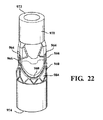
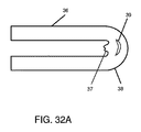
別の実施形態において、弁は、第1の端部と、該第1の端部の反対側に第2の端部とを有する、略環状の形状の支持構造を備える。第2の端部は、そこから長手方向に延びる複数の柱を備える。複合材料のシートが、柱から柱に向かって延び、ここで、リーフレットは柱の間にある該複合材料により画定される。1つの実施形態において、クッション部材が柱に結合されており、該クッション部材が、リーフレットが開放位置と閉鎖位置との間を往復運動するときに、該リーフレットにかかる応力と摩耗を最小限にすべく、柱とリーフレットとの間のクッションとなる。 In another embodiment, the valve comprises a substantially annular shaped support structure having a first end and a second end opposite the first end. The second end comprises a plurality of columns extending longitudinally from it. A sheet of composite material extends from pillar to pillar, where leaflets are defined by the composite material between the pillars. In one embodiment, the cushion member is coupled to a column, which minimizes stress and wear on the leaflet as it reciprocates between the open and closed positions. Therefore, it becomes a cushion between the pillar and the leaflet.
添付の図面は、本発明のさらなる理解のために含まれ、そして、本明細書の一部として組み込まれており、本明細書の一部を構成し、本発明の実施形態を示す。その記載は、本発明の原理を説明するのに役立つ。 The accompanying drawings are included for further understanding of the present invention and are incorporated as part of the present specification, forming a part of the present specification and showing embodiments of the present invention. The description helps explain the principles of the present invention.
図面にて図示する実施形態およびそれを説明するのに使用される特定の用語について記載する。しかしながら、このような実施形態は本発明の範囲を限定するものではなく、本明細書に記載する本発明の本質につき、例示した方法及び装置の改変や更なる修飾をも含め、発明に関する当業者にとって通常思いつく範囲の改変も可能であることを理解されたい。 Describe the embodiments illustrated in the drawings and the specific terms used to describe them. However, such embodiments do not limit the scope of the invention, and those skilled in the art relating to the invention, including modifications and further modifications of the methods and devices exemplified by the essence of the invention described herein. It should be understood that it is possible to modify the range that one usually thinks of.
本開示において使用される「マトリックス引張強度」は、特定の条件下における多孔性フルオロポリマー試料の引張強度を指す。試料の空隙率は、引張強度に、試料の密度に対するポリマーの密度の比を乗算した値によって求まる。 As used in the present disclosure, "matrix tensile strength" refers to the tensile strength of a porous fluoropolymer sample under certain conditions. The porosity of a sample is determined by multiplying the tensile strength by the ratio of the density of the polymer to the density of the sample.
本明細書中で使用される場合、用語「膜」は、限定されないが、例えば、延伸フルオロポリマーといった、単一の組成物を含む材料の多孔性シートを意味する。 As used herein, the term "membrane" means a porous sheet of material containing a single composition, such as, but not limited to, stretched fluoropolymers.
本明細書中で使用される場合、用語「複合材料」は、限定されないが、例えば、延伸フルオロポリマー等の膜と、限定されないが、例えば、フルオロエラストマー等のエラストマーとの組み合わせを指す。エラストマーは、膜の多孔性構造内に吸収されているか、又は、膜の片側又は両側に被覆されているか、又は、膜に被覆されていることと膜内に吸収されていることの組み合わせが可能である。 As used herein, the term "composite material" refers to a combination of a membrane, such as, but not limited to, a stretched fluoropolymer and an elastomer, such as, but not limited to, a fluoroelastomer. The elastomer can be absorbed within the porous structure of the membrane, or coated on one or both sides of the membrane, or a combination of being coated on the membrane and being absorbed within the membrane. Is.
本明細書中で使用される場合、用語「ラミネート」は、膜、複合材料、又はエラストマーなどの他の材料、及びこれらの組み合わせの多層のレイヤを指す。 As used herein, the term "laminate" refers to other materials such as membranes, composites, or elastomers, and multiple layers of combinations thereof.
本明細書中で使用される場合、用語「吸収」は、細孔の少なくとも一部に第2の材料を充填するのに用いる任意の方法を指す。 As used herein, the term "absorption" refers to any method used to fill at least a portion of the pores with a second material.
細孔がエラストマーで実質的に充填された多孔性膜では、所望の特性を測定するため、適切な溶媒を用いてエラストマーを溶解又は分解した後、リンスし得る。 In a porous membrane in which the pores are substantially filled with the elastomer, the elastomer can be dissolved or decomposed with a suitable solvent and then rinsed to measure the desired properties.
本明細書中で使用される場合、用語「エラストマー(elastomer)」は、1つのポリマー又は複数のポリマーの混合物のうちで、元の長さの少なくとも1.3倍まで伸ばすことができ、解放時には迅速にほぼ元の長さに戻る能力を有するものと定義される。「エラストマー性(elastomeric)」という用語は、ポリマーがエラストマーと同様の引張特性と復元特性を示すが、必ずしも引張及び/又は復元が同程度である必要はない特性を記述するのに用いる。 As used herein, the term "elastomer" can be extended to at least 1.3 times its original length in one polymer or a mixture of multiple polymers, and quickly upon release. It is defined as having the ability to return to almost its original length. The term "elastomeric" is used to describe properties in which a polymer exhibits similar tensile and restoring properties to elastomers, but does not necessarily have similar tensile and / or restoring properties.
本明細書中で使用される場合、用語「熱可塑性」は、溶融加工可能なポリマーと定義される。熱可塑性ポリマーとは異なり、「熱硬化性」ポリマーは、硬化させたときに不可逆的に固化する、又は「固まる」ポリマーと本明細書では定義される。 As used herein, the term "thermoplastic" is defined as a melt processable polymer. Unlike thermoplastic polymers, "thermosetting" polymers are defined herein as polymers that irreversibly solidify or "cure" when cured.
本明細書中で使用される場合、用語「微細繊維(fibril)」及び「繊維(fiber)」は互換的に使用される。 As used herein, the terms "fibril" and "fiber" are used interchangeably.
本明細書中で使用される場合、用語「合成ポリマー」は生物組織に由来しないポリマーを指す。 As used herein, the term "synthetic polymer" refers to a polymer that is not derived from biological tissue.
人工弁に関連して本出願で使用する場合、用語「リーフレット」は、圧力差の影響を受けて開放位置と閉鎖位置との間を移動するように作動する一方向弁の部品を指す。開放位置において、リーフレットは、血液が弁を通過して流れるようにする。閉鎖位置において、リーフレットは、弁を通過する逆流を実質的に遮断する。複数のリーフレットを備える実施形態において、各リーフレットは、少なくとも1つの隣接するリーフレットと協働して、血液の逆流を遮断する。本明細書における実施形態にかかるリーフレットは、複合材のレイヤを1枚又は複数枚含む。 As used in this application in connection with a prosthetic valve, the term "leaflet" refers to a component of a one-way valve that operates to move between an open and closed position under the influence of a pressure difference. In the open position, the leaflet allows blood to flow through the valve. In the closed position, the leaflet substantially blocks backflow through the valve. In embodiments with multiple leaflets, each leaflet works with at least one adjacent leaflet to block blood reflux. The leaflet according to the embodiment in the present specification includes one or more layers of composite material.
「フレーム」および「支持構造」という用語は、交換可能に使用され、人工弁として動作可能なようにリーフレットが結合または支持される要素を指す。支持構造は、ステントや導管(conduits)であってもよいが、これに限定されない。 The terms "frame" and "support structure" are used interchangeably to refer to the elements to which the leaflets are coupled or supported so that they can operate as prosthetic valves. The support structure may be, but is not limited to, a stent or conduit.
本明細書で使用する場合、「結合(couple)」とは、直接的または間接的に、永久にまたは一時的に、接続(connect)、取付(attach)、付着(adhere)、貼付(affix)、または接合(bond)することを意味する。 As used herein, "couple" means, directly or indirectly, permanently or temporarily, connect, attach, adhere, affix. , Or to bond.
本明細書で使用される場合、用語「接合」および「一緒に接合される」は、これに限定されないが、接着剤の使用といった結合を達成するために用いられる追加の材料を使用することなく、任意の適切な手段を用いて永久的に結合することを指す。複数の層を隣接する複数の層といった膜同士を一緒に接合するために使用される1つの方法は、焼結であるが、これに限定されない。接合は、複数の層が直接接触しているときに、複数の層を一緒にカレンダー加工したり延伸するとある程度生じる。 As used herein, the terms "joining" and "joining together" are not limited to, but without the use of additional materials used to achieve bonding, such as the use of adhesives. , Refers to permanent binding using any suitable means. One method used to join films together, such as multiple layers adjacent to each other, is, but is not limited to, sintering. Bonding occurs to some extent when the layers are calendared or stretched together when the layers are in direct contact.
本明細書で使用される場合、「層間剥離(delamination)」は、曲げにより裂けてしまう(split)ことを意味する。 As used herein, "delamination" means splitting due to bending.
本明細書中で使用される場合、用語「焼結」とは、材料を構成する物質の結晶融解温度以上の温度に材料を昇温させるプロセスを指す。 As used herein, the term "sintering" refers to the process of raising a material to a temperature above the crystal melting temperature of the material constituting the material.
本明細書中で使用される場合、用語「多孔性(porous)」とは、細孔を有することを指す。 As used herein, the term "porous" refers to having pores.
本明細書で使用される場合、用語「微小孔性(microporous)」および「微小孔性構造(microporous structure)」とは、小さな細孔および繊維を有することを指す。具体的には、膜中の繊維の平均直径は1マイクロメートル未満でなければならず、膜の平均流孔径は5マイクロメートル未満でなければならず、あるいは膜の比表面積は4.0m2/cc超でなければならない。これらの特徴のいずれかを有していれば、微小孔性を実証するのに十分である。 As used herein, the terms "microporous" and "microporous structure" refer to having small pores and fibers. Specifically, the average diameter of the fibers in the membrane must be less than 1 micrometer, the average pore diameter of the membrane must be less than 5 micrometers, or the specific surface area of the membrane must be 4.0 m 2 / cc. Must be super. Having any of these characteristics is sufficient to demonstrate microporous properties.
本明細書で使用する場合、用語「不浸透性」は、以下に説明する液体ピックアップ試験の性能において約10%未満の質量増加を示す物質を指す。あるいは、「不透過性」は、通気性試験にて説明されるような1000秒を超えるガーレー数を指す。いずれの特徴でも不透過性を実証するのに十分である。 As used herein, the term "impermeable" refers to a substance that exhibits a mass gain of less than about 10% in the performance of the liquid pickup test described below. Alternatively, "impermeable" refers to a number of galleys greater than 1000 seconds as described in the breathability test. Both features are sufficient to demonstrate impermeableness.
本明細書中で使用される場合、用語「モノレイヤ(monolayer)」は、1層(single ply)の薄いシート状の材料からなる構造体を指す。モノレイヤの一例は、1層(single ply)の薄いシート状の延伸PTFEである。よって、この延伸PTFEは、PTFEの結晶融解温度以上の温度に昇温してもしなくてもよい。モノレイヤの他の一例は、1層(single ply)の薄いシート状の延伸ポリエチレンである。 As used herein, the term "monolayer" refers to a structure made of a single ply thin sheet of material. An example of a monolayer is a single ply thin sheet of stretched PTFE. Therefore, this stretched PTFE may or may not be heated to a temperature equal to or higher than the crystal melting temperature of PTFE. Another example of a monolayer is a single ply thin sheet of stretched polyethylene.
本明細書中で使用される場合、用語「コヒーレントシングルレイヤ」は、少なくとも1層(one ply)、つまり、1層(one ply)又は隣接する複数の層が互いに結合するように一緒に接合した2層以上(two or more plies)が、通常混入してしまう不純物を除き唯1つの物質のみからなる同一材料からなる構造体を指す。「同一材料」としては、例えば、前述又は後述するような様々な形態のPTFEが挙げられる。さらに、例えば、「同一材料」として、コヒーレントシングルレイヤ内の様々な微細構造および/または微細繊維配向のePTFE材料が挙げられる。同様に、例えば、「同一材料」は、コヒーレントシングルレイヤ内の様々な微細構造の多孔質ポリエチレン膜が挙げられる。 As used herein, the term "coherent single layer" is used to join at least one layer, i.e., one layer or adjacent layers together so as to bond together. Two or more plies refers to a structure made of the same material consisting of only one substance excluding impurities that are normally mixed. Examples of the "same material" include various forms of PTFE as described above or described below. Further, for example, "same material" includes ePTFE materials with various microstructures and / or fine fiber orientations within a coherent single layer. Similarly, for example, "same material" includes porous polyethylene membranes of various microstructures within a coherent single layer.
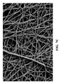
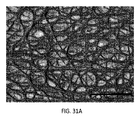
コヒーレントシングルレイヤは、織り物、編み物、フェルトまたは発泡体ではない。コヒーレントシングルレイヤには、これに限定されないが、引き伸ばされて細孔を生成したまたは生じた材料は含む。本明細書で使用される場合、コヒーレントシングルレイヤは繊維または微細繊維構造を画定するが、別個の繊維または微細繊維が長さ方向に絡み合って(entwined)材料を形成しているのではない。そうではなく、図7A、図7B、図7C、図30A、図30B、図31A、図31Bに示すように、多数の小径の微細繊維が相互接続されて(interconnected)コヒーレントシングルレイヤを形成する。コヒーレントシングルレイヤは、繊維を含み、該繊維はそれらの間の空間を画定する。 Coherent single layers are not woven, knitted, felt or foam. The coherent single-layer, but not limited to, stretched in material or resulting that generated the pores comprises. As used herein, a coherent single layer defines a fiber or fine fiber structure, but the separate fibers or fine fibers are not entwined to form a material. Instead, as shown in FIGS. 7A, 7B, 7C, 30A, 30B, 31A, 31B, a large number of small diameter fibrils are interconnected to form a coherent single layer. The coherent single layer contains fibers, which define the space between them.
コヒーレントシングルレイヤの一例はモノレイヤである。コヒーレントシングルレイヤの別の一例は、押出助剤を含んでいてもいなくてもよく、引き伸ばされていてもまたはカレンダー加工されてもされていなくてもよいPTFE押出物の2層以上からなる積層体(stack)である。ここで、該積層体は延伸されるが、特に、寸法安定性をもたらし、これらの層を互いに接合させ又はさらに一緒に接合させるために、その後PTFEの結晶融解温度以上の温度に昇温してもよいししなくてもよい。これらの処理工程により、得られた物品の層はそれらの境界面で互いに接合され、それによりコヒーレントシングルレイヤが生成される。コヒーレントシングルレイヤの別の一例は、2層以上の延伸されたPTFE膜からなる積層体であり、特に、寸法安定性をもたらし、これらの層を互いに接合させ又はさらに一緒に接合させるために、PTFEの結晶融解温度以上の温度に昇温されたものである。これらに限定されないが、ポリエチレンおよびポリプロピレンを含む他の材料を使用して、コヒーレントシングルレイヤを形成してもよい。 An example of a coherent single layer is a monolayer. Another example of a coherent single layer is a laminate of two or more layers of PTFE extruded material that may or may not contain an extrusion aid and may or may not be stretched or calendared. (Stack). Here, the laminate is stretched, but in particular, in order to provide dimensional stability and to join these layers together or even together, the temperature is then raised above the crystal melting temperature of PTFE. It may or may not be. Through these processing steps, the layers of the resulting article are joined together at their interface, thereby producing a coherent single layer. Another example of a coherent single layer is a laminate consisting of two or more stretched PTFE membranes, in particular to provide dimensional stability and to bond these layers together or even together. The temperature has been raised to a temperature higher than the crystal melting temperature of. Other materials, including but not limited to polyethylene and polypropylene, may be used to form the coherent single layer.
本明細書中で使用される場合、用語「不浸透性コヒーレントシングルレイヤ」は、エラストマーが細孔に含まれて該コヒーレントシングルレイヤが不透過性にされている多孔性のコヒーレントシングルレイヤを指す。 As used herein, the term "impermeable coherent single layer" refers to a porous coherent single layer in which an elastomer is contained in the pores to make the coherent single layer opaque.
本明細書中で使用される場合、用語「曲げ破壊」とは、例えば、以下に示すような圧縮曲げ試験の実施において裂け目(split)が生じる場合のように、材料構造が分かれてしまうことを指す。 As used herein, the term "bending fracture" means that the material structure is split, for example, when a split occurs in the performance of a compression bending test as shown below. Point to.
本開示は、長く必要とされてきた、心臓弁リーフレット等の高サイクル屈折インプラント用途(high−cycle flexural implant applications)における耐久性及び生体適合性の要求を満たす材料に関する。多孔性フルオロポリマー材料、より具体的にはエラストマーを含まないePTFEで形成された心臓弁リーフレットは、高サイクル屈折試験(high−cycle flex testing)及び動物移植において硬化することが観察されている。 The present disclosure relates to materials that meet the long-required demands for durability and biocompatibility in high-cycle flexural implant applications such as heart valve leaflets. Heart valve leaflets made of porous fluoropolymer material, more specifically elastomer-free ePTFE, have been observed to cure in high-cycle flex testing and animal transplantation.
一実施形態では、以下により詳しく説明するように、多孔性ポリマー製心臓弁リーフレットの屈曲耐久性は、比較的低強度のエラストマーを細孔に比較的大きな割合で添加することによって有意に増大した。場合により、追加のエラストマーレイヤを複合レイヤの間に追加してもよい。驚くべきことに、多孔性ポリマー膜にエラストマーを吸収させた実施形態では、エラストマーの存在によってリーフレットの全体的な厚さが増大し、エラストマーが付加されたことにより厚さが増大したポリマー部材は、屈曲耐久性を妨げたり低下させることがなかった。さらに、フルオロポリマー部材は、エラストマーの重量%の最小値に始まり、エラストマーの重量%が増大するにつれてよりよい性能を示し、その結果としてインビトロで4000万回超とサイクル寿命が有意に延長し、所定の制御された実験室条件では石灰化(calcification)の兆候を示さなかった。 In one embodiment, the bending durability of the porous polymer heart valve leaflet was significantly increased by adding a relatively low strength elastomer to the pores in a relatively large proportion, as described in more detail below. Optionally, additional elastomer layers may be added between the composite layers. Surprisingly, in the embodiment in which the porous polymer membrane absorbs the elastomer, the presence of the elastomer increases the overall thickness of the leaflet, and the addition of the elastomer increases the thickness of the polymer member. It did not interfere with or reduce flexion durability. In addition, fluoropolymer members start with a minimum of% by weight of the elastomer and show better performance as the% by weight of the elastomer increases, resulting in a significant increase in cycle life of over 40 million in vitro, predetermined. There were no signs of calcification under controlled laboratory conditions.
一実施形態による材料として、延伸フルオロポリマー膜とエラストマー性材料を含む複合材料がある。本発明の精神の範囲内でさまざまなタイプのフルオロポリマー膜とさまざまなタイプのエラストマー性材料の組み合わせが可能であることを容易に理解できるはずである。また、本発明の精神の範囲内で、エラストマー性材料には多数のエラストマーやさまざまなタイプの非エラストマー性成分(例えば無機充填剤、治療薬、放射線不透過性マーカーなど)を含めることが可能であることも容易に理解できるはずである。 As a material according to one embodiment, there is a composite material including a stretched fluoropolymer membrane and an elastomeric material. It should be easy to understand that within the spirit of the present invention it is possible to combine different types of fluoropolymer membranes with different types of elastomeric materials. Also, within the spirit of the invention, the elastomeric material can include a large number of elastomers and various types of non-elastomeric components (eg, inorganic fillers, therapeutic agents, radiation opaque markers, etc.). It should be easy to understand that there is.
いくつかの実施形態において、複合材料は、例えば米国特許第7,306,729号に一般的に記載されているように、多孔性ePTFE膜製の延伸フルオロポリマー材料を包含する。他のいくつかの実施形態において、複合材料は、多孔性ポリエチレン膜製のポリエチレン材料を包含する。 In some embodiments, the composite material includes a stretched fluoropolymer material made of a porous ePTFE membrane, for example as commonly described in US Pat. No. 7,306,729. In some other embodiments, the composite material includes a polyethylene material made of a porous polyethylene membrane.
実施形態で説明する延伸フルオロポリマー材料の形成に用いられる延伸可能なフルオロポリマーは、PTFEホモポリマーを含んでもよい。別の実施形態において、PTFEの混合物、延伸可能な修飾されたPTFE、及び/又はPTFEの延伸コポリマーを使用してもよい。好適なフルオロポリマー材料の例が、例えばBrancaの米国特許第5,708,044号、Baillieの米国特許第6,541,589号、Sabolらの米国特許第7,531,611号、Fordの米国特許出願第11/906,877号、Xuらの米国特許出願第12/410,050号に記載されているが、これらに限定されない。 The stretchable fluoropolymer used in the formation of the stretched fluoropolymer material described in the embodiments may include a PTFE homopolymer. In another embodiment, a mixture of PTFE, a stretchable modified PTFE, and / or a stretched copolymer of PTFE may be used. Examples of suitable fluoropolymer materials are, for example, Brancha U.S. Pat. No. 5,708,044, Baillie U.S. Pat. No. 6,541,589, Sabol et al. U.S. Pat. No. 7,531,611, Ford U.S. Patent Application No. 11 / 906,877, Xu et al. It is described in Patent Application No. 12 / 410,050, but is not limited thereto.
いくつかの実施形態にかかる延伸フルオロポリマーは、リーフレットを所望の性能にするため、好適な任意の微細構造を含んでもよい。一実施形態において、延伸フルオロポリマーは、例えばGoreの米国特許第3,953,566号に記載されているように、微細繊維によって相互に接続されたノードからなる微細構造を含むことができる。一実施形態において、延伸フルオロポリマー膜の微細構造は、図7Aの電子顕微鏡写真に示してあるように、微細繊維によって相互に接続されたノードからなる微細構造を含んでいる。微細繊維はノードから複数の方向へと延びているため、膜は一般に均一な構造を有する。この微細構造を持つ膜は、直交した2つの方向でのマトリックス引張強度の比が、約2未満、おそらくは約1.5未満でありうる。 The stretched fluoropolymers of some embodiments may contain any suitable microstructure to give the leaflet the desired performance. In one embodiment, the stretched fluoropolymer can include a microstructure consisting of nodes interconnected by fibrils, for example as described in Gore's US Pat. No. 3,953,566. In one embodiment, the microstructure of the stretched fluoropolymer membrane comprises a microstructure consisting of nodes interconnected by fibrils, as shown in the electron micrograph of FIG. 7A. Since the fibrils extend from the node in multiple directions, the membrane generally has a uniform structure. Membranes with this microstructure can have a ratio of matrix tensile strengths in two orthogonal directions of less than about 2, and perhaps less than about 1.5.
別の一実施形態において、延伸フルオロポリマーは、例えば図7Bと図7Cに示してあるように、そしてBacinoの米国特許第7,306,729号に一般に教示されているように、実質的に微細繊維のみからなる微細構造を有してもよい。図7Cは、図7Bに示した延伸フルオロポリマー膜の拡大図で、実質的に微細繊維のみからなる均一な微細構造をより明瞭に示す。図7Bと図7Cに示す実質的に微細繊維のみからなる延伸フルオロポリマー膜は、例えば約20 m2/g超、又は約25 m2/g超という大きな表面積を有してもよく、いくつかの実施形態において、強度のバランスが非常によく、直交した2つの方向でのマトリックス引張強度の積が少なくとも1.5×105 MPa2、及び/又は直交した2つの方向でのマトリックス引張強度の比が約2未満、おそらくは約1.5未満という材料を提供することができる。実施形態によると、延伸フルオロポリマー膜が約5μm未満、約1μm未満、及び約0.10μm未満の平均流孔径を有し得ると予想される。 In another embodiment, the stretched fluoropolymer comprises substantially only fine fibers, for example as shown in FIGS. 7B and 7C, and as generally taught in US Pat. No. 7,306,729 of Bacino. It may have a fine structure. FIG. 7C is an enlarged view of the stretched fluoropolymer membrane shown in FIG. 7B, which more clearly shows a uniform microstructure consisting substantially only of fine fibers. The stretched fluoropolymer membrane consisting substantially only of fine fibers shown in FIGS. 7B and 7C may have a large surface area of, for example, more than about 20 m 2 / g, or more than about 25 m 2 / g, and some In the embodiment, the strengths are very well balanced, the product of the matrix tensile strengths in the two orthogonal directions is at least 1.5 × 10 5 MPa 2 , and / or the ratio of the matrix tensile strengths in the two orthogonal directions is Materials that are less than about 2, and perhaps less than about 1.5, can be provided. According to embodiments, it is expected that stretched fluoropolymer membranes can have an average pore size of less than about 5 μm, less than about 1 μm, and less than about 0.10 μm.
リーフレットを所望の性能にするため、いくつかの実施形態による延伸フルオロポリマーは適切な任意の厚さと質量にしてもよい。非常に薄くて厚さが約1.0μm未満の延伸フルオロポリマー膜を用いることが望ましい場合がある。別の実施形態において、厚さが約0.1μm超且つ約20μm未満の延伸フルオロポリマー膜を使用することが望ましい場合も。延伸フルオロポリマー膜は、約1 g/m2未満〜約50 g/m2超の比質量を有することがある。 In order to obtain the desired performance of the leaflet, the stretched fluoropolymer according to some embodiments may have any suitable thickness and mass. It may be desirable to use a stretched fluoropolymer membrane that is very thin and less than about 1.0 μm thick. In another embodiment, it may be desirable to use a stretched fluoropolymer membrane with a thickness greater than about 0.1 μm and less than about 20 μm. Stretched fluoropolymer membranes may have a specific mass of less than about 1 g / m 2 to more than about 50 g / m 2 .
一実施形態による延伸フルオロポリマーを含む膜は、密度が約2.2 g/cm3のPTFEで約50 MPa〜約400 MPa以上の範囲のマトリックス引張強度を有することがある。 The membrane containing the stretched fluoropolymer according to one embodiment may have a matrix tensile strength in the range of about 50 MPa to about 400 MPa or more at PTFE with a density of about 2.2 g / cm 3 .
追加の材料を細孔の中、又は膜の材料の中、又は膜の層の間に組み込んでリーフレットの所望の特性を増大させてもよい。一実施形態による複合体は、厚さが約500μm〜約0.3μm未満のフルオロポリマー膜を含み得る。 Additional material may be incorporated in the pores, in the membrane material, or between the membrane layers to increase the desired properties of the leaflet. The complex according to one embodiment may comprise a fluoropolymer membrane having a thickness of about 500 μm to less than about 0.3 μm.
少なくともいくつかの重要なやり方では、エラストマーと組み合わせた延伸フルオロポリマー膜の実施形態で、高サイクルで屈曲させるインプラントの用途、例えば心臓弁リーフレットで用いるのに必要な性能属性が得られる。例えば、エラストマーを添加すると、ePTFEのみの材料で観察される硬直がなくなるか減少することにより、リーフレットの疲労特性が改善される。それに加え、材料の永続的な変形、例えばしわや折れ目が生じる結果として性能が低下する可能性が減少する。一実施形態において、エラストマーは、延伸フルオロポリマー膜の多孔性構造内の細孔の体積又は空間の実質的にすべてを占める。別の一実施形態において、エラストマーは、少なくとも1つのフルオロポリマー層の実質的にすべての細孔の中に存在する。エラストマーが細孔の体積を充填している、すなわちエラストマーが実質的にすべての細孔の中に存在していることで、望みに反して複合体に組み込まれる可能性のある異物のための空間が小さくなる。そのような異物の一例は、カルシウムである。カルシウムが例えば心臓弁リーフレットで使用する複合材料に組み込まれると、繰り返して動作させている間に物理的損傷が発生し、リーフレットに穴が形成されて血行力学が悪化する可能性がある。 In at least some important ways, embodiments of stretched fluoropolymer membranes in combination with elastomers provide the performance attributes required for use in high cycle flexing implant applications, such as heart valve leaflets. For example, the addition of an elastomer improves the fatigue properties of the leaflet by eliminating or reducing the stiffness observed with ePTFE-only materials. In addition, it reduces the potential for performance degradation as a result of permanent deformation of the material, such as wrinkles and creases. In one embodiment, the elastomer occupies substantially all of the volume or space of the pores in the porous structure of the stretched fluoropolymer membrane. In another embodiment, the elastomer is present in substantially all pores of at least one fluoropolymer layer. The elastomer fills the volume of the pores, i.e. the elastomer is present in virtually every pore, which is a space for foreign matter that can be undesirably incorporated into the complex. Becomes smaller. An example of such a foreign substance is calcium. When calcium is incorporated into a composite material used, for example, in a heart valve leaflet, physical damage can occur during repeated operation, puncturing the leaflet and deteriorating hemodynamics.
一実施形態において、ePTFEと組み合わせたエラストマーは、例えば米国特許第7,462,675号に記載されているように、テトラフルオロエチレン(TFE)とペルフルオロメチルビニルエーテル(PMVE)の熱可塑性コポリマーである。上述のように、エラストマーを延伸フルオロポリマー膜と組み合わせ、エラストマーが、延伸フルオロポリマー膜の中の実質的にすべての空隙又は細孔を占めるようにする。延伸フルオロポリマー膜の細孔へのエラストマーのこのような充填は、さまざまな方法で実行できる。一実施形態において、延伸フルオロポリマー膜の細孔を充填する方法は、延伸フルオロポリマー膜の細孔の一部又は全体に好適に流入するような粘度と表面張力を持つ溶液を作るのに適した溶媒にエラストマーを溶かすステップと、その溶媒を蒸発させて充填剤を残すステップを含む。 In one embodiment, the elastomer combined with ePTFE is a thermoplastic copolymer of tetrafluoroethylene (TFE) and perfluoromethyl vinyl ether (PMVE), eg, as described in US Pat. No. 7,462,675. As described above, the elastomer is combined with the stretched fluoropolymer membrane so that the elastomer occupies virtually all voids or pores in the stretched fluoropolymer membrane. Such filling of the pores of the stretched fluoropolymer membrane with the elastomer can be performed in a variety of ways. In one embodiment, the method of filling the pores of a stretched fluoropolymer membrane is suitable for producing a solution having a viscosity and surface tension such that it preferably flows into some or all of the pores of the stretched fluoropolymer membrane. It involves dissolving the elastomer in a solvent and evaporating the solvent to leave a filler.
別の一実施形態において、延伸フルオロポリマー膜の細孔を充填する方法は、分散液によって充填剤を延伸フルオロポリマー膜の細孔の一部又は全体に満たすステップを含む。 In another embodiment, the method of filling the pores of a stretched fluoropolymer membrane comprises the step of filling some or all of the pores of the stretched fluoropolymer membrane with a filler with a dispersion.
別の一実施形態において、延伸フルオロポリマー膜の細孔を充填する方法は、熱及び/又は圧力の条件下で多孔性延伸フルオロポリマー膜をエラストマーのシートと接触させ、エラストマーを延伸フルオロポリマー膜の細孔に流入させるステップを含む。 In another embodiment, the method of filling the pores of a stretched fluoropolymer membrane is to contact the porous stretched fluoropolymer membrane with a sheet of elastomer under heat and / or pressure conditions and to bring the elastomer into a stretched fluoropolymer membrane. Including the step of flowing into the pores.
別の一実施形態において、延伸フルオロポリマー膜の細孔を充填する方法は、最初にエラストマーのプレポリマーを細孔に満たし、次いでそのエラストマーを少なくとも部分的に硬化させることにより、延伸フルオロポリマー膜の細孔の中でエラストマーを重合させるステップを含む。 In another embodiment, the method of filling the pores of a stretched fluoropolymer film is to first fill the pores with a prepolymer of an elastomer and then at least partially cure the elastomer of the stretched fluoropolymer film. It involves the step of polymerizing the elastomer in the pores.
フルオロポリマー材料又はePTFEから構成されたリーフレットは、エラストマーの重量%が最小値に到達した後、一般にエラストマーの割合が増加するにつれて性能が向上し、その結果としてサイクルの寿命が有意に延長した。一実施形態において、ePTFEと組み合わせたエラストマーは、米国特許第7,462,675号や、当業者に公知である他の文献に記載されているように、テトラフルオロエチレンとペルフルオロメチルビニルエーテルの熱可塑性コポリマーである。例えば実施例1に示す別の一実施形態において、ePTFEに対して53重量%のエラストマーを含む複合体からリーフレットを形成してサイクル試験を実施した。サイクルが約2億回でいくらかの硬直化が観察されたが、流体力学への影響はほんのわずかであった。実施例2のようにエラストマーの重量%を約83重量%まで増やすと、約2億回のサイクルでは、硬直化、又は流体力学のマイナスの変化は観察されなかった。逆に、比較例Bのような非複合体製リーフレットでは、すなわちすべてがePTFEであってエラストマーを含まないリーフレットでは、サイクルが約0.4億回になるまでに深刻な硬直化が明らかになった。これらの実施例から証明されるように、多孔性フルオロポリマー膜の耐久性は、比較的低強度のエラストマーをフルオロポリマー部材の細孔にかなり大きな割合で添加することによって有意に増大させることができる。フルオロポリマー膜の材料強度が大きいことによっても特定の構造を非常に薄くすることができる。 Leaflets made of fluoropolymer material or ePTFE generally improved in performance as the proportion of elastomers increased after the weight% of elastomer reached the minimum, resulting in a significant extension of cycle life. In one embodiment, the elastomer combined with ePTFE is a thermoplastic copolymer of tetrafluoroethylene and perfluoromethyl vinyl ether, as described in US Pat. No. 7,462,675 and other documents known to those of skill in the art. For example, in another embodiment shown in Example 1, a leaflet was formed from a composite containing 53% by weight of elastomer with respect to ePTFE and a cycle test was performed. Some rigidity was observed with about 200 million cycles, but the effect on hydrodynamics was negligible. When the weight% of the elastomer was increased to about 83% by weight as in Example 2, no rigidity or negative change in hydrodynamics was observed in about 200 million cycles. Conversely, non-composite leaflets such as Comparative Example B, that is, leaflets that were all ePTFE and did not contain elastomers, revealed severe rigidity by the time the cycle reached about 40 million times. As evidenced by these examples, the durability of the porous fluoropolymer membrane can be significantly increased by adding a relatively low strength elastomer to the pores of the fluoropolymer member in a fairly large proportion. .. The high material strength of the fluoropolymer membrane can also make certain structures very thin.
使用するのに適した別の生体適合性ポリマーとして、ウレタン、シリコーン(有機ポリシロキサン)、ケイ素−ウレタンのコポリマー、スチレン/イソブチレンコポリマー、ポリイソブチレン、ポリエチレン−コ−ポリ(酢酸ビニル)、ポリエステルコポリマー、ナイロンコポリマー、フッ化炭化水素ポリマーと、これらそれぞれのコポリマー又は混合物からなる群が挙げられるが、これらに限定されない。 Other biocompatible polymers suitable for use include urethane, silicone (organic polysiloxane), silicon-urethane copolymers, styrene / isobutylene copolymers, polyisobutylene, polyethylene-co-poly (vinyl acetate), polyester copolymers, Examples include, but are not limited to, nylon copolymers, fluorinated hydrocarbon polymers, and copolymers or mixtures thereof.
延伸フルオロポリマーに加えて、他の生体適合性合成ポリマーも多孔性膜としての使用に好適であり得る。以下に提供するように、微小孔性ポリエチレンを含む実施形態が、特定の目的に好適な生体適合性ポリマーとして提供される。 In addition to stretched fluoropolymers, other biocompatible synthetic polymers may also be suitable for use as porous membranes. Embodiments comprising microporous polyethylene are provided as biocompatible polymers suitable for a particular purpose, as provided below.
微小孔性ポリエチレン膜の一実施形態には、実質的に全ての繊維が約1μm未満の直径を有する繊維を含む材料のシートが含まれる。微小孔性ポリエチレン膜の別の実施形態には、実質的に全ての繊維が約1μm未満の直径を有する繊維を含む不織布材料のシートが含まれる。場合によっては、約10.0μm未満の厚みを有する非常に薄い微小孔性ポリエチレン膜を使用することが望まれることもある。他の実施形態において、約0.6μm未満の厚みを有する微小孔性ポリエチレン膜を使用することが望まれることもある。 One embodiment of the microporous polyethylene membrane includes a sheet of material containing fibers in which substantially all fibers have a diameter of less than about 1 μm. Another embodiment of the microporous polyethylene membrane includes a sheet of a non-woven material containing fibers in which substantially all fibers have a diameter of less than about 1 μm. In some cases, it may be desirable to use a very thin microporous polyethylene membrane with a thickness of less than about 10.0 μm. In other embodiments, it may be desirable to use a microporous polyethylene membrane with a thickness of less than about 0.6 μm.
本明細書における実施形態で開示する微小孔性膜の構造は、その材料の比表面積から判断することによって、織物や、ニットや、繊維巻き(fiber windings)などの他の構造と区別され得ることが理解される。本明細書における微小孔性膜の実施形態は、約4.0m2/cc超の比表面積を有する。本明細書における微小孔性膜の他の実施形態によると、約10.0m2/cc超の比表面積を有する。本明細書中における実施形態は、約4.0 m2/cc超〜約60 m2/cc超の比表面積を有する膜が、リーフレット材料として使用したときに心臓弁の少なくとも、これらに限定されないが、耐久性や耐用年数に有意な改善を提供することが理解される。 The structure of the microporous membrane disclosed in the embodiments herein can be distinguished from other structures such as woven fabrics, knits and fiber windings by judging from the specific surface area of the material. Is understood. Embodiments of microporous membranes herein have a specific surface area of greater than about 4.0 m 2 / cc. According to other embodiments of microporous membranes herein, it has a specific surface area of more than about 10.0 m 2 / cc. Embodiments herein are limited to, but not limited to, membranes having a specific surface area of greater than about 4.0 m 2 / cc to greater than about 60 m 2 / cc of heart valves when used as leaflet materials. It is understood to provide significant improvements in durability and service life.
本明細書における実施形態で開示した微小孔性膜は、その材料の繊維直径から判断することによって、織物や、ニットや、繊維巻きなどの他の構造と区別され得ることが理解される。本明細書における微小孔性膜の実施形態は、繊維の大部分が約1μm未満の直径を有する繊維を含む。本明細書における微小孔性膜の他の実施形態は、その大部分が約0.1μm未満の直径を有する繊維を含む。本明細書における実施形態は、その大部分が約1μm未満〜約0.1μm未満の繊維を含む膜は、リーフレット材料として使用されるときに心臓弁の少なくとも、これらに限定されないが、耐久性と耐用年数に有意な改善を提供することが認識される。 It is understood that the microporous membrane disclosed in the embodiments herein can be distinguished from other structures such as woven fabrics, knits and fiber wraps by judging from the fiber diameter of the material. Embodiments of microporous membranes herein include fibers in which most of the fibers have a diameter of less than about 1 μm. Other embodiments of microporous membranes herein include fibers, most of which have a diameter of less than about 0.1 μm. In the embodiments herein, membranes, most of which contain fibers less than about 1 μm to less than about 0.1 μm, are durable and durable, but not limited to, at least for heart valves when used as leaflet materials. It is recognized that it provides a significant improvement in years.
実施形態の微小孔性ポリマー膜は、所望のリーフレット性能を達成するための任意の好適な微細構造及びポリマーを含んでもよい。いくつかの実施形態において、微小孔性ポリマー膜は、例えば実施例4に含まれる材料に関して図30A及び30Bに示されている、及び実施例5に含まれる材料に関して図31A及び31Bに示されているものといった、実質的に繊維のみからなる微細構造を有する多孔性ポリエチレンである。図30は、約1μm未満の直径を有する繊維のみを実質的に有する多孔性ポリエチレン膜の実質的に均一な微細構造を示す。多孔性ポリエチレン膜は、0.010mmの厚み、31.7%の空隙率、6.42g/m2の質量/面積、及び28.7m2/ccの比表面積を有していた。 The microporous polymer membrane of the embodiment may contain any suitable microstructure and polymer to achieve the desired leaflet performance. In some embodiments, the microporous polymer membranes are shown, for example, in FIGS. 30A and 30B for the material contained in Example 4 and in FIGS. 31A and 31B for the material contained in Example 5. It is a porous polyethylene having a fine structure consisting substantially only of fibers. FIG. 30 shows a substantially uniform microstructure of a porous polyethylene membrane having substantially only fibers having a diameter of less than about 1 μm. The porous polyethylene membrane had a thickness of 0.010 mm, a porosity of 31.7%, a mass / area of 6.42 g / m 2 , and a specific surface area of 28.7 m 2 / cc.
それぞれ表面及び横断面図である図31A及び31Bは、実施例5に関して以下で記載したプロセスに従って延伸した、それぞれ表面及び横断面図である図30A及び30Bで示したのと同じ多孔性ポリエチレン膜である。延伸ポリエチレン膜は、約1μm未満の直径を有する繊維のみを実質的に有する実質的に均一の微細構造を保っている。延伸ポリエチレン膜は、0.006mmの厚み、44.3%の空隙率、3.14g/m2の質量/面積、及び18.3m2/ccの比表面積を有していた。実施形態によると、微小孔性ポリエチレン膜が、約5μm未満、約1μm未満、さらに約0.10μm未満の平均流孔径を有しうることが予想される。 31A and 31B, which are surface and cross-sectional views, are the same porous polyethylene membranes as shown in FIGS. 30A and 30B, which are surface and cross-sectional views, respectively, stretched according to the process described below for Example 5. is there. The stretched polyethylene membrane maintains a substantially uniform microstructure having substantially only fibers having a diameter of less than about 1 μm. The stretched polyethylene membrane had a thickness of 0.006 mm, a porosity of 44.3%, a mass / area of 3.14 g / m 2 , and a specific surface area of 18.3 m 2 / cc. According to embodiments, it is expected that microporous polyethylene membranes can have an average pore diameter of less than about 5 μm, less than about 1 μm, and even less than about 0.10 μm.
延伸フルオロポリマーに加えて、限定されないが、例えば、延伸ポリマー膜といった他の生体適合性合成ポリマーも多孔性膜としての使用に好適であり得る。以下に提供するように、微小孔性ポリエチレンを含む実施形態が、特定の目的に好適な生体適合性ポリマーとして提供される。 In addition to stretched fluoropolymers, other biocompatible synthetic polymers, such as, but not limited to, stretched polymer membranes, may also be suitable for use as porous membranes. Embodiments comprising microporous polyethylene are provided as biocompatible polymers suitable for a particular purpose, as provided below.
複数の実施形態において、人工弁リーフレットは、多孔性合成ポリマーのシングルレイヤ、つまり、多孔性であるコヒーレントシングルレイヤを備え、ここで、細孔がエラストマーを含むことで該コヒーレントシングルレイヤが不浸透性になり、リーフレット材料が画定され、これからリーフレットが作成される。コヒーレントシングルレイヤを備えるリーフレット材料は、圧縮曲げ試験において立証されるように層間剥離抵抗性を示す。 In a plurality of embodiments, the artificial valve leaflet comprises a single layer of porous synthetic polymer, i.e., a coherent single layer that is porous, wherein the coherent single layer is impervious due to the inclusion of elastomer in the pores. The leaflet material is defined, and the leaflet is created from this. Leaflet materials with coherent single layers exhibit delamination resistance as evidenced in compression bending tests.
他の複数の実施形態において、人工弁リーフレットは、多孔性である少なくとも1つのコヒーレントシングルレイヤを備え、ここで、細孔がエラストマーを含むことで該少なくとも1つのコヒーレントシングルレイヤが不浸透性になる。 In a plurality of other embodiments, the prosthetic valve leaflet comprises at least one coherent single layer that is porous, where the pores contain an elastomer that makes the at least one coherent single layer impermeable. ..
他の複数の実施形態において、人工弁リーフレットは、多孔性である複数のコヒーレントシングルレイヤを備え、ここで、細孔がエラストマーを含むことで該複数のコヒーレントシングルレイヤが不浸透性になり、これにより前記リーフレットも不浸透性になる。複数のコヒーレントシングルレイヤは、それらの間のエラストマーにより一緒に結合され、マルチコヒーレントシングルレイヤラミネートを形成する。このマルチコヒーレントシングルレイヤラミネートは、リーフレット材料を画定し、この材料からリーフレットを作成できる。 In a plurality of other embodiments, the prosthetic valve leaflet comprises a plurality of coherent single layers that are porous, wherein the pores contain an elastomer that makes the plurality of coherent single layers impervious. This also makes the leaflet impervious. Multiple coherent single layers are joined together by an elastomer between them to form a multi-coherent single layer laminate. This multi-coherent single layer laminate can define a leaflet material and make leaflets from this material.
本明細書に提示される実施形態によって提供されるリーフレット材料は、人工弁として機能する構造を提供するリーフレットに形成できることが理解される。このようなリーフレットは、更に、縫製、接着、クリップ止め、その他の機械的取り付けを含む任意の適切な手段によってフレームに取り付けてもよい。一実施形態によれば、フレームは、治療部位における血管内送達および展開のために選択的に直径方向に調整可能である。 It is understood that the leaflet material provided by the embodiments presented herein can be formed into leaflets that provide a structure that acts as a prosthetic valve. Such leaflets may also be attached to the frame by any suitable means, including sewing, gluing, clipping and other mechanical attachments. According to one embodiment, the frame is selectively diametrically adjustable for intravascular delivery and deployment at the treatment site.
複数の実施形態において、フレームおよび該フレームに結合したリーフレットを備える人工弁を提供する。リーフレットは、唯一のコヒーレントシングルレイヤおよびエラストマーを備える。コヒーレントシングルレイヤは、多孔性構造を有する。エラストマーは細孔内に存在することでコヒーレントシングルレイヤが不浸透性になる。複数の実施形態において、コヒーレントシングルレイヤは、モノレイヤを備える。換言すれば、コヒーレントシングルレイヤは、1層の多孔性合成ポリマー膜を備える。 In a plurality of embodiments, an artificial valve including a frame and a leaflet coupled to the frame is provided. The leaflet has only one coherent single layer and elastomer. The coherent single layer has a porous structure. The presence of the elastomer in the pores makes the coherent single layer impervious. In a plurality of embodiments, the coherent single layer comprises a monolayer. In other words, the coherent single layer comprises a single layer of porous synthetic polymer membrane.
他の複数の実施形態において、コヒーレントシングルレイヤは、本質的にその材料のみからなり、一緒に接合した、複数層の同一材料の多孔性合成ポリマー膜を備える。他の複数の実施形態において、コヒーレントシングルレイヤは、本質的にその材料のみからなり、一緒に接合した、複数層の同一材料の延伸合成ポリマー膜を備える。他の複数の実施形態において、コヒーレントシングルレイヤは、複数層のePTFE膜の積み重ね焼結体(sintered stack)を備える。いくつかの実施形態によれば、合成ポリマー膜は多孔性にされてから、積み重ね構成に配置され、追加の材料を使用することなく、任意の適切な手段により一緒に接合される。いくつかの実施形態によれば、ePTFE膜は、延伸されてから、積み重ね構成に配置され、複数層のePTFE膜を一緒に接合させるためにPTFEの結晶融解温度を超える温度に昇温される。他の複数の実施形態において、複数層の多孔性又は非多孔性合成ポリマー膜は積み重ね構成に配置されてから、多孔性又はより多孔性(つまり、細孔をより大きくする)にされ、そしてその後、追加の材料を使用することなく、任意の適切な手段により一緒に接合される。他の複数の実施形態において、複数層のPTFE押出シートは積み重ね構成に配置されてから、延伸され、そしてその後複数の延伸PTFEシートを一緒に接合させるためにPTFEの結晶融解温度を超える温度に昇温される。 In a plurality of other embodiments, the coherent single layer comprises multiple layers of a porous synthetic polymer membrane of the same material, consisting essentially of that material only and bonded together. In a plurality of other embodiments, the coherent single layer comprises multiple layers of stretched synthetic polymer membranes of the same material, which consist essentially of only that material and are joined together. In a plurality of other embodiments, the coherent single layer comprises a multi-layered ePTFE film sintered stack. According to some embodiments, the synthetic polymer membranes are made porous and then placed in a stacking configuration and joined together by any suitable means without the use of additional materials. According to some embodiments, the ePTFE membrane is stretched and then placed in a stacking configuration and heated to a temperature above the crystal melting temperature of PTFE to join the multi-layered ePTFE membranes together. In other embodiments, the multi-layer porous or non-porous synthetic polymer membrane is placed in a stacking configuration and then made porous or more porous (ie, larger pores), and then , Are joined together by any suitable means, without the use of additional materials. In other embodiments, the multi-layered PTFE extruded sheet is placed in a stacking configuration, then stretched, and then raised to a temperature above the crystal melting temperature of the PTFE to join the plurality of stretched PTFE sheets together. Be warmed.
いくつかの実施形態によれば、コヒーレントシングルレイヤは、5μm未満の孔径を有する。 According to some embodiments, the coherent single layer has a pore size of less than 5 μm.
いくつかの実施形態によれば、コヒーレントシングルレイヤは、約1μm未満の孔径を有する。 According to some embodiments, the coherent single layer has a pore size of less than about 1 μm.
いくつかの実施形態によれば、唯一のコヒーレントシングルレイヤを備え、該コヒーレントシングルレイヤの細孔内にエラストマーを含むリーフレットは、少なくとも10重量%のエラストマーを有する。 According to some embodiments, a leaflet comprising only one coherent single layer and containing an elastomer in the pores of the coherent single layer has at least 10% by weight of elastomer.
いくつかの実施形態によれば、リーフレットは、少なくとも2つの直交した方向に約35 MPa超の引張強度を有する。本明細書に記載のいくつかの実施形態によれば、リーフレットは、最も強い方向の引張強度の、該最も強い方向に直交する方向の引張強度に対する比が約2未満である。 According to some embodiments, the leaflet has a tensile strength of more than about 35 MPa in at least two orthogonal directions. According to some embodiments described herein, leaflets have a ratio of tensile strength in the strongest direction to tensile strength in the direction orthogonal to the strongest direction of less than about 2.
複数の実施形態において、リーフレットは、本明細書に記載の圧縮曲げ試験に合格している。圧縮曲げ試験は、高応力状態で長時間保持された場合の材料の凝集破壊(cohesive failure)に対する抵抗性を評価する。図32Aは、圧縮曲げ試験に合格しなかった圧縮曲げ試験試料36の端面図である。図32B、図32Cは、圧縮曲げ試験に合格した圧縮曲げ試験試料36の端面図を示す。圧縮曲げ試験試料36が圧縮曲げ試験に合格しない場合、少なくとも1つのスプリット39が圧縮曲げ試験試料36の厚さ内に形成される。合成ポリマー膜のモノレイヤを備えるコヒーレントシングルレイヤの実施形態では、スプリットがモノレイヤ内に形成されてもされなくてもよい。複数層の多孔性合成ポリマー膜を備えるコヒーレントシングルレイヤの実施形態では、スプリットが合成ポリマー膜の2層の間に形成されてもされなくてもよい。屈曲部38における圧縮曲げ試験試料36はしわまたは膨らみ37を示すことがあり、これは1つまたは複数のスプリット39が形成されない限り、圧縮曲げ試験に不合格となる破壊状態とはみなされない。
In a plurality of embodiments, the leaflet has passed the compression bending test described herein. The compressive bending test evaluates the resistance of a material to cohesive failure when it is held for a long time in a high stress state. FIG. 32A is an end view of the compression
複数の実施形態において、リーフレットは、本明細書に記載の圧縮永久ひずみ試験において10%未満の圧縮永久ひずみを有する。圧縮永久ひずみ試験は、材料を圧縮荷重下に置き、それを回復させた後の厚さの変化に抵抗する材料の能力を評価する。例えば、圧縮永久ひずみの値が低い場合、間接的に、多孔性材料の細孔がエラストマーを含有することを示す。多孔性材料にエラストマーを添加することにより、圧縮永久ひずみを減少させることができる。 In a plurality of embodiments, the leaflet has a compression set of less than 10% in the compression set test described herein. The compression set test evaluates the ability of a material to resist changes in thickness after it has been placed under a compressive load and restored. For example, a low compression set value indirectly indicates that the pores of the porous material contain an elastomer. By adding an elastomer to the porous material, compression set can be reduced.
エラストマーを多孔性構造体に導入する前後の材料を区別するために光透過率試験を行った。コヒーレントシングルレイヤ及びエラストマーを備えるリーフレット材料は、少なくとも60%の光透過率を示した。いくつかの実施形態によれば、リーフレットは、本明細書に記載の光透過率試験において少なくとも80%の光透過率を有する。光透過率試験は、光が散乱せずサンプルを透過する能力を評価する。光透過率が高い場合、多孔性材料が不浸透性になるように多孔性材料の孔がエラストマーで十分に充填されていることを示す。 A light transmittance test was performed to distinguish the materials before and after introducing the elastomer into the porous structure. Leaflet materials with coherent single layers and elastomers showed at least 60% light transmission. According to some embodiments, the leaflet has a light transmittance of at least 80% in the light transmittance test described herein. The light transmittance test evaluates the ability of light to pass through a sample without scattering. A high light transmittance indicates that the pores of the porous material are sufficiently filled with the elastomer so that the porous material becomes impermeable.
コヒーレントシングルレイヤの構造体は、以下の3つの方法のいずれかで作成することができる。
1.1層の多孔性合成ポリマー膜、換言すれば、モノレイヤを作成する。
2.同一材料の多孔性合成ポリマー膜を複数層積み重ねて、追加の材料を使用することなく、任意の適切な手段を用いて一緒に接合する。
3.多孔性又は非多孔性の合成ポリマー膜を複数層積み重ねて、多孔性又はより多孔性(つまり、細孔をより大きくする)にし、追加の材料を使用することなく、任意の適切な手段を用いて一緒に接合する。
A coherent single layer structure can be created in one of three ways:
Create a 1.1-layer porous synthetic polymer membrane, in other words, a monolayer.
2. 2. Multiple layers of porous synthetic polymer membranes of the same material are stacked and joined together using any suitable means, without the use of additional materials.
3. 3. Multiple layers of porous or non-porous synthetic polymer membranes are stacked to make them porous or more porous (ie, make the pores larger), using any suitable means without the use of additional materials. And join together.
コヒーレントシングルレイヤ、具体的にはPTFE膜の実施形態の例として、上述のコヒーレントシングルレイヤの3種の構造体は、以下のように作成される。以下ではPTFEについて説明するが、ポリエチレンおよびポリプロピレンを含むがこれらに限定されない他の材料を使用して、実施例9に示すようなコヒーレントシングルレイヤを形成してもよい。 As an example of the embodiment of the coherent single layer, specifically the PTFE film, the above-mentioned three types of structures of the coherent single layer are prepared as follows. Although PTFE will be described below, other materials including, but not limited to, polyethylene and polypropylene may be used to form a coherent single layer as shown in Example 9.
1つの実施形態によれば、リーフレットは、多孔性である少なくとも1つのePTFE膜を備え、ここで、細孔がエラストマーを含むことで該ePTFE膜が不浸透性になり、これによりリーフレットも不浸透性になる。本明細書では、唯一のePTFE膜をモノレイヤと呼ぶ。 According to one embodiment, the leaflet comprises at least one ePTFE membrane that is porous, where the pores contain an elastomer that makes the ePTFE membrane impermeable, which also imperviously the leaflet. Become a sex. In this specification, the only ePTFE film is referred to as a monolayer.
1つの実施形態によれば、細孔内に存在するエラストマーは架橋されていてもよい。 According to one embodiment, the elastomer present in the pores may be crosslinked.
1つの実施形態によれば、リーフレットは、多孔性であるモノレイヤを備え、モノレイヤは、リーフレットが不浸透性になるように細孔内にエラストマーを含む。1つの実施形態によれば、リーフレットは、少なくとも60%の光透過率を有し得る。少なくとも60%の光透過率だと、モノレイヤが不透過性になるのに十分なエラストマーが細孔内に存在することが確実である。 According to one embodiment, the leaflet comprises a porous monolayer, which comprises an elastomer in the pores such that the leaflet is impermeable. According to one embodiment, the leaflet can have a light transmittance of at least 60%. At least 60% light transmittance ensures that there is enough elastomer in the pores to make the monolayer opaque.
モノレイヤから構築されたリーフレットは、約150μm以下の厚さを有してもよい。 The leaflet constructed from the monolayer may have a thickness of about 150 μm or less.
別の1つの実施形態によれば、リーフレットは、多孔性である複数層のePTFE膜を備え、これらの複数層は、延伸されてから、積み重ね構成に配置され、これらの複数層を一緒に接合するようにPTFEの結晶融解温度を超える温度に昇温され、多孔性のコヒーレントシングルレイヤは作成される。リーフレットは、コヒーレントシングルレイヤの細孔にエラストマーを更に含むことで、コヒーレントシングルレイヤが不浸透性になり、これによりリーフレットも不浸透性になる。 According to another embodiment, the leaflet comprises a multi-layered ePTFE membrane that is porous, the multi-layers being stretched and then placed in a stacking configuration and the multi-layers joined together. The temperature is raised above the melting temperature of the PTFE crystal so that a porous coherent single layer is created. The leaflet further contains an elastomer in the pores of the coherent single layer, which makes the coherent single layer impervious, which also makes the leaflet impermeable.
1つの実施形態によれば、リーフレットは、上述の方法で形成された多孔性である複数層のePTFE膜を備え、これらの複数層が一緒に接合されて多孔性のコヒーレントシングルレイヤは作成される。リーフレットが、少なくとも60%の光透過率を有するように、リーフレットは、細孔内にエラストマーを更に含む。少なくとも60%の光透過率だと、コヒーレントシングルレイヤが不浸透性になり、これによりリーフレットも不浸透性になるのに十分なエラストマーが細孔内に存在することが確実である。 According to one embodiment, the leaflet comprises a multi-layered ePTFE membrane that is porous formed by the method described above, and the multi-layers are joined together to create a porous coherent single layer. .. The leaflet further contains an elastomer in the pores so that the leaflet has a light transmittance of at least 60%. At least 60% light transmission makes the coherent single layer impervious, which ensures that there is enough elastomer in the pores to make the leaflet also impermeable.
1つの実施形態によれば、細孔内に存在するエラストマーは架橋されていてもよい。 According to one embodiment, the elastomer present in the pores may be crosslinked.
上述のようなコヒーレントシングルレイヤを含むリーフレットは、約150μm以下の厚さを有してもよい。 The leaflet containing the coherent single layer as described above may have a thickness of about 150 μm or less.
別の1つの実施形態によれば、リーフレットは、複数層のPTFE押出シートを備え、これらの複数層が積み重ねられてから、多孔性又はより多孔性になるように延伸され、そして延伸後、これらの複数層を更に接合するようにPTFEの結晶融解温度を超える温度に昇温され、多孔性のコヒーレントシングルレイヤは作成される。リーフレットが、少なくとも60%の光透過率を有するように、リーフレットは、コヒーレントシングルレイヤの細孔内にエラストマーを更に含み、これによりコヒーレントシングルレイヤが不浸透性になっている。 According to another embodiment, the leaflet comprises multiple layers of PTFE extruded sheet, these multiple layers are stacked and then stretched to be porous or more porous, and after stretching, these. The temperature is raised above the crystal melting temperature of PTFE so as to further join the plurality of layers of the above, and a porous coherent single layer is created. The leaflet further contains an elastomer in the pores of the coherent single layer so that the leaflet has a light transmission of at least 60%, which makes the coherent single layer impermeable.
1つの実施形態によれば、細孔内に存在するエラストマーは架橋されていてもよい。 According to one embodiment, the elastomer present in the pores may be crosslinked.
1つの実施形態によれば、リーフレットは、上述の方法で形成された複数層のePTFE膜を備え、これらの複数層が一緒に接合されて多孔性のコヒーレントシングルレイヤは作成される。リーフレットが、少なくとも60%の光透過率を有するように、リーフレットは、細孔内にエラストマーを更に含む。少なくとも60%の光透過率だと、コヒーレントシングルレイヤが不浸透性になるのに十分なエラストマーが細孔内に存在することが確実である。 According to one embodiment, the leaflet comprises a multi-layered ePTFE membrane formed by the method described above, the multi-layers being joined together to create a porous coherent single layer. The leaflet further contains an elastomer in the pores so that the leaflet has a light transmittance of at least 60%. At least 60% light transmission ensures that there is enough elastomer in the pores to make the coherent single layer impermeable.
上述のようにコヒーレントシングルレイヤから構築されたリーフレットは、約150μm以下の厚さを有してもよい。 The leaflet constructed from the coherent single layer as described above may have a thickness of about 150 μm or less.
図34は、折り畳まれたリーフレット材料からなるリーフレット60を有する人工弁70の一実施形態の斜視図である。各リーフレット60は、それを構成するリーフレット材料が折り畳まれている折り畳み縁(folded egde)54によって画定されるリーフレット自由縁62を有する。リーフレット材料50内に形成された切断縁によって画定されるリーフレット自由縁62とは対照的に、折り畳み縁54は、リーフレット材料50の1つまたは複数のレイヤおよび/または層の切断縁を露出させない。
FIG. 34 is a perspective view of an embodiment of an
図35Aおよび図35Bは、それぞれ、折り畳み線(fold line)53に沿って矢印59によって示されるおおよその方向に折り畳み可能な2つの折り畳み部分(folding portions)52a、52bを有するリーフレット材料50の端面図および上面図である。図35Cおよび図35Dは、それぞれ、2つの折り畳み部分52a、52bが折り畳まれた、図35Aのリーフレット材料50の端面図および上面図であり、2つの折り畳み部分52a、52bが重なって折り畳まれたリーフレット材料50aを画定している。折り畳まれたリーフレット材料50aは、折り畳み縁54と、この折り畳み縁54の反対側の折り畳まれていない縁55とを画定する。折り畳み縁54は、図34に示されるような、人工弁70として組み立てられたときにリーフレット60が折り畳まれたリーフレット自由縁64を画定する。換言すれば、この実施形態では、リーフレット自由縁62は、折り畳まれたリーフレット自由縁64である。
35A and 35B are end views of the
図36は、図34の折り畳まれたリーフレット自由縁64を有する人工弁70を製造する方法の一実施形態による、マンドレル1200上に組み立てられ、折り畳まれたリーフレット材料50aで巻き付けられるプロセス中である弁フレーム1000の斜視図である。弁フレーム1000は、マンドレル1200上にスライドされる。折り畳まれたリーフレット材料50aは、弁フレーム1000の弁フレーム外面1002の周りに一旦巻き付けられ、これに結合される。折り畳み縁54は、弁フレーム1000のフレームベース1103と反対側に面しており、折り畳まれたリーフレット自由縁64を画定する。図34は、上述の方法によって作成した折り畳まれたリーフレット自由縁64を示す人工弁70の斜視図である。
FIG. 36 is a valve in the process of being assembled on a
他の複数の実施形態において、折り畳まれたリーフレット材料50aは、弁フレーム外面ではなく、弁フレーム1000の弁フレーム内面に結合されてもよい。別の実施形態によれば、リーフレット材料50がマンドレル1200の周りに巻き付けられ、弁フレーム1000は、折り畳み部分52aなどのリーフレット材料50の一部の上をスライドする。弁フレームを過ぎて伸びるリーフレット材料50の部分、例えば折り畳み部分52bは、フレーム外面上で裏返り、折り畳み縁54を画定する。リーフレット材料50は、弁フレーム1000およびリーフレット材料50自身と結合し、折り畳まれたリーフレット材料50aおよび折り畳まれたリーフレット自由縁64を画定する。
In a plurality of other embodiments, the folded
他の複数の実施形態において、折り畳まれたリーフレット材料50aから単一のリーフレット60を切り出すことができる。図37は、折り畳まれたリーフレット材料50aの上面図であり、折り畳み縁54と、リーフレット60を画定するカットパターン58とを示している。図38は、折り畳まれたリーフレット材料50aからカットパターン58に沿って切断された後、折り畳まれたリーフレット自由縁64を有するリーフレット60の平面図である。折り畳まれたリーフレット材料50aは、カットパターン58に沿って切断され、リーフレット60のカットライン57を形成する。カットライン57に隣接するリーフレット60の部分は、限定されないが、例えば、弁フレーム1000または導管のような構造体に後に結合することができる部分である。折り畳まれたリーフレット材料50aの折り畳み縁54の、構造体に直接結合されていない部分は、折り畳まれたリーフレットの自由縁64を画定する。
In a plurality of other embodiments, a
複数の実施形態において、折り畳まれたリーフレットの自由縁64を含むリーフレット60のリーフレット材料50は、1つまたは複数の膜、ラミネート、および/またはコヒーレントシングルレイヤを有する複合材料を含んでもよい。
In multiple embodiments, the
以下の非限定的な実施例は、様々な実施形態をさらに例示するために提供される。 The following non-limiting examples are provided to further illustrate various embodiments.
実施例1
一実施形態により、心臓弁リーフレットを、延伸フルオロポリマー膜とエラストマー性材料を有する複合材料から形成し、バルーンを伸展可能な金属製ステントに接合した。そのプロセスを以下に記載する。
Example 1
In one embodiment, the heart valve leaflet was formed from a composite material with a stretched fluoropolymer membrane and an elastomeric material and the balloon was bonded to an extendable metal stent. The process is described below.
1つのePTFE層を折り曲げて合計で4つの層にすることにより、ツール用の厚い犠牲クッションパッド又は層を形成した。ePTFE層は、幅が約5cm(2インチ)、厚さが約0.5mm(0.02インチ)であり、圧縮性が大きいため、クッションパッドを形成する。図1と図2からわかるように、次にこのクッションパッド200を、全体を100で示したリーフレットツールの上で引き伸ばした(図2)。リーフレットツール100は、リーフレット部102と、本体部104と、底端部106を備えている。リーフレットツール100のリーフレット部102は、一般にアーチ形凸状である端部面103を有する。リーフレットツール100を矢印(図2A)で示した方向に押し付けることにより、クッションパッド200をリーフレットツール100のリーフレット部102の端部面103の上で引き伸ばして滑らかにした。クッションパッド200の周縁部202をリーフレットツール100の底端部106の上まで引き伸ばし、捩ってクッションパッド200を所定の位置に保持した(図2B)。
A thick sacrificial cushion pad or layer for the tool was formed by folding one ePTFE layer into a total of four layers. The ePTFE layer has a width of about 5 cm (2 inches) and a thickness of about 0.5 mm (0.02 inches), and has high compressibility, so that it forms a cushion pad. As can be seen from FIGS. 1 and 2, the
図2Bを参照すると、次に、前のステップにおいてクッションパッド200で覆ったリーフレットツール100のリーフレット部102の上に剥離層204を引き伸ばした。一実施形態において、剥離層204は、フッ化エチレンプロピレン(FEP)の層を外面又は外側に沿って配置した実質的に非多孔性のePTFEから作製した。FEP層がクッションパッド200の方を向くともに、実質的に非多孔性のePTFEがクッションパッド200の外側を向くようにして、すなわちクッションパッド200から離れるようにして、リーフレットツール100の上で剥離層204を引き伸ばした。剥離層204は、厚さが約25μmであり、十分な長さと幅があるため、リーフレットツール100の底端部106の上まで引っ張ることができた。前のステップにおけるクッションパッド200と同様、剥離層204の周縁部206をリーフレットツール100の底端部106に向かって引っ張った後、捩ってリーフレットツール100の底端部106に取り付け、剥離層204を所定の位置に保持した。次に、必要に応じ、剥離層204のFEP層を点状に溶融させ、ハンダごてを用いてクッションパッド200に固定した。
Referring to FIG. 2B, the
上記ステップ1)及び2)の操作を繰り返し、3つの独立したリーフレットツールを用意した。それぞれのリーフレットツールが、剥離層で覆ったクッションパッドを有していた。 By repeating the above steps 1) and 2), three independent leaflet tools were prepared. Each leaflet tool had a cushion pad covered with a release layer.
フルオロエラストマーを吸収させたePTFE膜を含む複合材料から、一実施形態によるリーフレット材料を形成した。円形マンドレルを幅が約10cmの複合材料のシートで包み、チューブを形成した。複合材料は、3つの層で構成されていた。すなわち、2つのePTFE製外側層と、その間に挟まれたフルオロエラストマー製内側層である。ePTFE膜は、米国特許第7,306,729号に記載されている一般的な教示内容に従って製造した。フルオロエラストマーは、米国特許第7,462,675号に記載されている一般的な教示内容に従って製造した。別のフルオロエラストマーも好適であることがあり、米国特許出願公開第2004/0024448号に記載されている。 A leaflet material according to one embodiment was formed from a composite material containing an ePTFE film having absorbed a fluoroelastomer. The circular mandrel was wrapped in a sheet of composite material about 10 cm wide to form a tube. The composite was composed of three layers. That is, two ePTFE outer layers and a fluoroelastomer inner layer sandwiched between them. The ePTFE membrane was manufactured according to the general teachings described in US Pat. No. 7,306,729. Fluoroelastomers were manufactured according to the general teachings of US Pat. No. 7,462,675. Other fluoroelastomers may also be suitable and are described in US Patent Application Publication No. 2004/0024448.
ePTFE膜は以下の特性を有していた:厚さ=約15μm;最大強度の方向のMTS=約400 MPa;直交する方向のMTS強度=約250 MPa;密度=約0.34 g/cm3;IBP=約660 kPa。 The ePTFE film had the following properties: thickness = about 15 μm; MTS in the direction of maximum intensity = about 400 MPa; MTS strength in the orthogonal direction = about 250 MPa; density = about 0.34 g / cm 3 ; IBP = Approximately 660 kPa.
コポリマーは、約65〜70重量%のペルフルオロメチルビニルエーテルと、それと補完的に(complementally)約35〜30重量%のテトラフルオロエチレンから本質的になる。 The copolymer consists essentially of about 65-70% by weight of perfluoromethyl vinyl ether and complementally about 35-30% by weight of tetrafluoroethylene.
ePTFEに対するフルオロエラストマーの重量%は約53%であった。 The weight% of fluoroelastomer relative to ePTFE was about 53%.
多層複合体は以下の特性を有していた:厚さ約40μm;密度約1.2 g/cm3;破断させるための力/最大強度の方向の幅=約0.953 kg/cm;最大強度の方向の引張強度=約23.5 MPa(3,400 psi);破断させるための力/直交する方向の幅=約0.87 kg/cm;直交する方向の引張強度=約21.4 MPa(3,100 psi);IPA泡立ち点(バブルポイント)=約12.3 MPa超;ガーレー数=約1,800秒超;質量/面積=約14 g/m2。 The multilayer composite had the following properties: thickness about 40 μm; density about 1.2 g / cm 3 ; force to break / width in the direction of maximum strength = about 0.953 kg / cm; in the direction of maximum strength Tensile strength = approx. 23.5 MPa (3,400 psi); force to break / width in orthogonal direction = approx. 0.87 kg / cm; tensile strength in orthogonal direction = approx. 21.4 MPa (3,100 psi); IPA foaming point (bubble point) ) = Approximately 12.3 MPa or more; Garley number = Approximately 1,800 seconds or more; Mass / Area = Approximately 14 g / m 2 .
以下の試験法を利用してePTFE層と多層複合体の特徴を調べた。 The characteristics of the ePTFE layer and the multilayer complex were investigated using the following test methods.
厚さは、日本で製造されたミツトヨ社の挟みゲージAbsolute、直径12.7mm(0.50インチ)、モデルID−C112E、シリアル番号10299を用いて測定した。密度は、化学天秤Mettler PM400(ニュージャージー州、米国)を用いて重量/体積を計算することによって求めた。破断させる力と引張強度は、平坦な向かい合った顎部を有するInstron社のモデル5500R(ノーウッド、マサチューセッツ州)を用い、負荷セル50kg、ゲージ長=25.4cm、クロスヘッド速度=25mm/分(歪み速度=100%/分)で測定した。IPA泡立ち点は、圧力勾配の速度を1.38 kPa/秒(0.2 psi/秒)、試験面積を3.14cm2にして、IPA泡立ち点試験機であるPressure Regulator Industrial Data Systems社のモデルLG-APOK(ソールトレイクシティ、ユタ州、米国)によって測定した。ガーレー数は、ガーレー試験機(モデル4110(トロイ、ニューヨーク州、米国))を用い、124mmの水圧下で100cm3の空気が6.45cm2のサンプルを通過する時間(単位は秒)として求めた。
The thickness was measured using a Mitutoyo pinch gauge Absolute manufactured in Japan, diameter 12.7 mm (0.50 inch), model ID-C112E, and serial number 10299. Density was determined by calculating weight / volume using a chemical balance, Mettler PM400, NJ, USA. The breaking force and tensile strength are the Instron model 5500R (Norwood, Mass.) With flat facing jaws,
特に断わらない限り、これらの試験法を利用して以下の実施例のデータを得た。 Unless otherwise noted, these test methods were used to obtain data for the following examples.
膜の強度が大きい方向がマンドレルの軸方向を向くようにして、直径約28mm(1.1インチ)のマンドレルを複合材料層で包んだ。それぞれの複合材料層は、2つのePTFE製外側層と、その間に配置されたフルオロエラストマー製内側層を備えている。一実施形態において、一般にマンドレルの外周を、螺旋状にせずに、4つの複合材料層で包んだ。複合材料はわずかに粘着性を持っていたため、自己接着が可能であった。マンドレルの表面上のまま、おおよそマンドレルの長軸に沿って複合材料に長手方向に切り込みを入れ、約10cm(4インチ)×約90mm(3.5インチ)のシートを形成した。 A mandrel with a diameter of about 28 mm (1.1 inches) was wrapped in a composite layer so that the direction of increased membrane strength was oriented toward the axial direction of the mandrel. Each composite layer comprises two ePTFE outer layers and a fluoroelastomer inner layer located between them. In one embodiment, the outer circumference of the mandrel was generally wrapped in four composite layers rather than spirally. The composite was slightly sticky and was capable of self-adhesion. While remaining on the surface of the mandrel, longitudinal cuts were made in the composite approximately along the long axis of the mandrel to form a sheet of approximately 10 cm (4 inches) x approximately 90 mm (3.5 inches).
得られたリーフレット材料(すなわちステップ4からの複合材料)のシートを切断し、剥離層204で覆ったクッションパッド200を有するリーフレットツール100を包んだ。より具体的には、図3A〜図3Cに示してあるように、リーフレット材料300を平坦な切断面の上に置いた。次に、クッションパッド200と剥離層204を有するリーフレットツール100をリーフレット材料300の上にほぼ図示してあるように揃えた。次に、カミソリの刃を用いてリーフレット材料300に4つのスリット302、304、306、308を形成した。一対のスリット302、304は、リーフレットツール100の一方の側から延びて、リーフレット材料300の一端300aで終わっている。他方の一対のスリット306、308は、リーフレットツール100の反対側から延びて、リーフレット材料300の反対側の端300bで終わっている。スリット302、304、306、308は、リーフレットツール100のリーフレット部102から離れていた。スリット302、304、306、308は、リーフレットツール100の下方で突起していなかった。個々のスリットの幅は実際の縮尺では示していないことに注意されたい。リーフレット材料300のスリット302、304、306、308により、折り畳み部分310と、一対の帯状部312、314と、リーフレット材料315の過剰材料部が形成された。次に、折り畳み部分310を全体として図3Cの矢印316で示した方向に折り曲げ、これまでのステップでクッションパッド200と剥離層204によって覆ってあったリーフレットツール100の上で滑らかにした。
A sheet of the resulting leaflet material (ie, the composite material from step 4) was cut and wrapped in a
次に、リーフレット材料315をリーフレット部102の上、特にリーフレットツール100の端部面103の上に引き伸ばし、滑らかにした。ステップ4)と5)を繰り返し、3つの独立なリーフレット組立体を形成した。次に、これら3つのリーフレット組立体402、404、406をまとめて固定し、図4に示すような三リーフレット組立体400を形成した。図には3つの独立なリーフレット組立体402、404、406が示されていて、それぞれが、三リーフレット組立体400の周辺部を超えておおよそ径方向に延びるリーフレット材料315の過剰材料部を有する。
The
次に、三リーフレット組立体のリーフレットツールの端部面と係合するキャビティを有し、余分なリーフレット領域を切除して3つのリーフレットを形成する基部ツールを設けた。図5Aを参照すると、基部ツールは全体を500で示してあり、端部501と反対側の底端部503の間を長手方向に延びている。3つの凹状キャビティ502、504、506が基部ツール500の端部501に形成されている。それぞれの凹状キャビティ502、504、506は、3つのリーフレット組立体402、404、406のうちの1つの端部面103をフィットさせるように、又は収容するように形成される。径方向に延びる3つの要素508、510、512が、基部ツール500のその端部から外側に延びている。それぞれの要素508、510、512は、隣り合ったペアの凹状キャビティ502、504、506の間に配置されている。
Next, a base tool having a cavity that engages with the end face of the leaflet tool of the three leaflet assembly and cutting off the excess leaflet area to form the three leaflets was provided. With reference to FIG. 5A, the base tool is shown entirely at 500 and extends longitudinally between the
次に、ステップ1と2でリーフレットツールを用意したのと同様のやり方で、圧縮パッドと剥離層(図示せず)を有する基部ツール500を用意した。それぞれのリーフレットツールに関してステップ1と2で説明したように、圧縮パッドと剥離層を同様にして引き伸ばして基部ツール500に固定し、基部ツール組立体を形成した。
Next, a
図5Bに示すように、次に、基部ツール組立体(便宜上、基部ツール500として示し、クッションパッドと剥離層は示さない)と三リーフレット組立体(全体を400で示す)をおおよそ軸方向で揃えて各リーフレットツール100の端部面(図示せず)を基部ツール(全体を500で示す)の端部501の凹状キャビティ(図示せず)のうちの1つの中に収容し、組み合わされたツール組立体を形成した。
As shown in FIG. 5B, the base tool assembly (shown as
次に、バルーンを延伸させることのできる金属製ステントを製造した。壁の厚さが約0.5mm(0.020インチ)で直径が約2.5cm(1.0インチ)のステンレス鋼製チューブ316をレーザーで切断した。このチューブにパターンを刻み、環状に切断したステントフレーム又は支持構造を形成し、図6Aにおいて、全体を600とし、平坦にした状態の平面図として示してある。支持構造600は、複数の小さな閉鎖セル602と、複数の大きな閉鎖セル604と、複数のリーフレット閉鎖セル606を備えている。図6Aでは、平坦にした状態の平面図であるという理由で、複数のリーフレット閉鎖セル606のうちの1つが開放セルのように見えることに注意されたい。小さな閉鎖セル602、大きな閉鎖セル604、及びリーフレットの閉鎖セル606は、おおよそ列に沿って配置され、支持構造600の環状形を形成する。
Next, a metal stent capable of stretching the balloon was manufactured. A
次に、レーザーで切断したステントフレームにポリマー材料を付着させた。最初に、直径が約2.5cm(1.0インチ)のマンドレル(図示せず)をePTFE膜の犠牲用圧縮層で重複がないようにして包んだ。ePTFE膜の犠牲用圧縮層は、厚さが約0.5mm(0.02インチ)、幅が約10cm(4インチ)であり、柔軟性と圧縮性を有しており柔軟な犠牲用圧縮層になっていた。 Next, the polymer material was attached to the laser-cut stent frame. First, a mandrel (not shown) about 2.5 cm (1.0 inch) in diameter was wrapped in a sacrificial compression layer of ePTFE membrane without overlap. The sacrificial compression layer of the ePTFE film is about 0.5 mm (0.02 inch) thick and about 10 cm (4 inch) wide, and is flexible and compressible, making it a flexible sacrificial compression layer. It was.
次に、実質的に非多孔性のePTFEフィルムの4つの層で、圧縮層膜の上からマンドレルを包んだ。実質的に非多孔性のePTFEフィルムは、厚さが約25μm(0.001インチ)、幅が約10cm(4インチ)であり、一方の側にFEP層を備えていた。実質的に非多孔性のePTFEフィルムを、FEPがマンドレルとは逆の方向を向くようにして包んだ。実質的に非多孔性のePTFEフィルムは、ステップ2)で上述して剥離層の特性を有していた。 The mandrel was then wrapped over the compression layer membrane with four layers of substantially non-porous ePTFE film. The substantially non-porous ePTFE film was about 25 μm (0.001 inch) thick, about 10 cm (4 inch) wide, and had an FEP layer on one side. A substantially non-porous ePTFE film was wrapped with the FEP facing in the opposite direction of the mandrel. The substantially non-porous ePTFE film had the characteristics of the release layer described above in step 2).
溶融押し出しと引き伸ばしを利用してタイプ1(ASTM D3368)FEPの薄いフィルムを構成した。ステップ10では圧縮層膜で包み、ステップ11では実質的に非多孔性のePTFEフィルムの4つの層で包んだマンドレルに、このタイプ1(ASTM D3368)FEPの薄いフィルムをさらに10層追加した。タイプ1(ASTM D3368)FEPフィルムは、厚さが約40μm(0.0016インチ)、幅が約7.7cm(3インチ)であった。 A thin film of type 1 (ASTM D3368) FEP was constructed using melt extrusion and stretching. An additional 10 layers of this Type 1 (ASTM D3368) FEP thin film were added to the mandrel wrapped in a compression layer film in step 10 and in four layers of a substantially non-porous ePTFE film in step 11. The Type 1 (ASTM D3368) FEP film was approximately 40 μm (0.0016 inches) thick and approximately 7.7 cm (3 inches) wide.
次に、この包まれた状態のマンドレルを空気対流炉の中で約320℃にて約5分間にわたって熱処理した後、冷却した。 Next, the wrapped mandrel was heat-treated in an air convection furnace at about 320 ° C. for about 5 minutes and then cooled.
次に、支持構造(図6Aでは600で示す)を、包まれた状態で熱処理したマンドレルの上に配置した。次に、包まれた状態のマンドレルの上に配置した支持構造を、(ステップ12で用意した)タイプ1(ASTM D3368)FEPフィルムの2つの追加層で包んだ。 The support structure (shown by 600 in FIG. 6A) was then placed on the wrapped and heat treated mandrel. The support structure placed on top of the wrapped mandrel was then wrapped in two additional layers of Type 1 (ASTM D3368) FEP film (prepared in step 12).
次に、包まれた状態のマンドレルとその上に支持されている支持構造を空気対流炉の中で約320℃にて約10分間にわたって熱処理した後、冷却することにより、ポリマーで被覆した支持構造を形成した。 Next, the wrapped mandrel and the support structure supported on it are heat-treated in an air convection furnace at about 320 ° C. for about 10 minutes, and then cooled to cover the support structure with a polymer. Was formed.
次に、ポリマーで被覆した支持構造を外科用メスでトリムし、トリムされたステントフレームを形成した。このステントフレームは、図6Bでは全体を700で、平坦にした状態の平面図として示してある。より具体的には、1つのやり方では、支持構造(図6A、600)の縁部から約2mm(0.08インチ)はみ出した状態でポリマー被覆をトリムし、縁部の輪郭708をさまざまな形態にした。別のやり方では、ポリマー被覆をすべてのセルに広げ、各セルの中にウェブを形成した。どちらの場合にも、支持構造600がポリマー被覆702の中に完全に封入された状態で、トリムしたステントフレーム700が形成された。トリムしたステントフレーム700は、数と一般に形状が複数のリーフレット閉鎖セル606(図6A)に対応する複数のリーフレット開口部704を含む。さらに、図6Bに示してあるように、小さな閉鎖セルのポリマー被覆702のそれぞれにスリット706が形成されている。具体的には、各スリット706は直線状であり、環状支持構造600の長手方向の中心軸(図示せず)におおよそ平行である。
The polymer-coated support structure was then trimmed with a scalpel to form a trimmed stent frame. In FIG. 6B, the stent frame is 700 as a whole and is shown as a flat plan view. More specifically, one approach trimmed the polymer coating about 2 mm (0.08 inches) over the edge of the support structure (FIGS. 6A, 600) to give the edge contour 708 a variety of forms. .. Alternatively, the polymer coating was spread across all cells, forming a web within each cell. In both cases, the trimmed
次に、トリムしたステントフレームを、ステップ8から得た組み合わされたツール組立体の上に配置した。リーフレットツールのリーフレット部(102)を、トリムしたステントフレームのリーフレット開口部(図6Bでは704)に揃えた。3つの余分なリーフレット材料領域(図4では315)をステントフレームのリーフレット開口部を通じて引き出した。3対の帯状部(図3Aでは312、314)のそれぞれをスリット(図6Bでは706)の1つを通じて引き出し、トリムしたステントフレームの周囲に巻いた。帯状部の各ペアを、互いに反対側の向きに巻いた。次に、ハンダごてを用い、6つの帯状部を、トリムしたステントフレームに熱融着させた。 The trimmed stent frame was then placed on top of the combined tool assembly obtained from step 8. The leaflet portion (102) of the leaflet tool was aligned with the leaflet opening (704 in FIG. 6B) of the trimmed stent frame. Three extra leaflet material areas (315 in FIG. 4) were pulled out through the leaflet opening of the stent frame. Each of the three pairs of strips (312, 314 in FIG. 3A) was pulled out through one of the slits (706 in FIG. 6B) and wrapped around the trimmed stent frame. Each pair of strips was wound in opposite directions. Next, using a soldering iron, the six strips were heat fused to the trimmed stent frame.
次に、組み合わされたツール組立体(ステップ8)と、巻いて熱融着させた帯状部を有するトリムしたステントフレームを、回転チャック機構に取り付けた。次に、この回転チャック機構を調節して長手方向の圧縮負荷を軽くかけた。次に、ハンダごてを用い、余分なリーフレット材料領域(図4では315)を基部ツール(図5では500)に付着させた。 The combined tool assembly (step 8) and a trimmed stent frame with rolled and heat-sealed strips were then attached to the rotary chuck mechanism. Next, the rotary chuck mechanism was adjusted to lightly apply a compression load in the longitudinal direction. An extra leaflet material area (315 in FIG. 4) was then attached to the base tool (500 in FIG. 5) using a soldering iron.
次に、ステップ18の組み合わされたツールを、(ステップ12からの)タイプ1(ASTM D3368)FEPフィルムの2つの追加層で包んだ。次に、複合体(ステップ4)の3つの追加層で上から包み、トリムしたステントフレームに付着させた。 The combined tools of step 18 were then wrapped in two additional layers of Type 1 (ASTM D3368) FEP film (from step 12). It was then wrapped from above with three additional layers of the complex (step 4) and attached to the trimmed stent frame.
最終熱処理の準備として、圧縮テープと圧縮繊維の剥離層と犠牲層を、ステップ19から得た組立体の周辺部と長手方向の両方に付着させた。その後の熱処理の間、圧縮テープ/繊維が周辺部と長手方向の両方から組立体と接触してその組立体を圧縮する。圧縮テープの犠牲層をステップ19から得た組立体の周囲に螺旋状に巻いた。この圧縮テープは、ステップ10にて前述したePTFEの犠牲圧縮層の特性を有していた。次に、ePTFE圧縮繊維を圧縮テープの上からきつく巻いた。外周に圧縮繊維を密な間隔で螺旋状に約100回巻いた。ePTFE圧縮繊維は直径が約1mm(0.04インチ)であり、十分に加熱すると長手方向に収縮する構造であった。次に、固定された組立体を回転チャック機構から外した。次に、犠牲圧縮テープの3つの層を組立体のまわりに長手方向に巻いた。次に、長手方向の圧縮テープの上から圧縮繊維を約20回長手方向に巻いた。 In preparation for the final heat treatment, compression tape and compression fiber release and sacrifice layers were applied to both the periphery and longitudinal of the assembly obtained from step 19. During the subsequent heat treatment, the compression tape / fiber contacts the assembly from both the periphery and longitudinally to compress the assembly. A sacrificial layer of compression tape was spirally wound around the assembly obtained from step 19. This compression tape had the characteristics of the sacrificial compression layer of ePTFE described in step 10. The ePTFE compressed fiber was then tightly wrapped over the compression tape. Compressed fibers were spirally wound around the outer circumference at close intervals about 100 times. The ePTFE compressed fiber had a diameter of about 1 mm (0.04 inch) and had a structure that contracted in the longitudinal direction when sufficiently heated. Next, the fixed assembly was removed from the rotary chuck mechanism. Three layers of sacrificial compression tape were then wrapped longitudinally around the assembly. Next, the compression fiber was wound about 20 times in the longitudinal direction over the compression tape in the longitudinal direction.
次に、ステップ20から得た組立体を空気対流炉の中で約280℃にて約90分間にわたって熱処理した後、室温の水で急冷した。この熱処理ステップにより、ステップ4に記載したリーフレット材料の製造に用いるePTFE膜の細孔の中に熱可塑性フルオロエラストマーが流入しやすくなる。 Next, the assembly obtained from step 20 was heat-treated in an air convection furnace at about 280 ° C. for about 90 minutes, and then rapidly cooled with water at room temperature. This heat treatment step facilitates the inflow of the thermoplastic fluoroelastomer into the pores of the ePTFE film used in the production of the leaflet material described in step 4.
次に、犠牲用圧縮テープ/繊維を除去した。ポリマー材料をトリムしてリーフレットと基部ツールを分離した。次に、ステントのポリマー層をトリムし、リーフレットが付着したステントフレームを取り出した。次にリーフレットをトリムそ、図8に全体を800で示す弁組立体を得た。 The sacrificial compression tape / fiber was then removed. The polymer material was trimmed to separate the leaflet from the base tool. The polymer layer of the stent was then trimmed and the stent frame with leaflets attached was removed. Next, the leaflet was trimmed to obtain a valve assembly shown by 800 in FIG.
得られた弁組立体800は、一実施形態によれば、複数の細孔を有する少なくとも1つのフルオロポリマー層と、その少なくとも1つのフルオロポリマー層の実質的にすべての細孔の中に存在するエラストマーとを含む複合材料から形成されたリーフレット802を備えている。各リーフレット802は、血液が弁組立体を通って流れることを阻止する図9Aに示す閉鎖位置と、血液が弁組立体を通って流れることが可能な図9Bに示す開放位置の間を移動可能である。したがって弁組立体800のリーフレット802は、閉鎖位置と開放位置の間を繰り返して移動して、ヒト患者の血流の方向をおおよそ調節する。
The resulting
弁を横断する典型的な解剖学的圧力と流れをリアルタイム脈拍再現装置で測定して特定の弁組立体に関する初期データセット、すなわち“ゼロ疲労”データセットを生成させることにより、各弁組立体のリーフレットの性能を特徴づけた。次に弁組立体を高速疲労試験機に移し、約2.07億回にわたってサイクルさせた。約1億回の各ブロックが終了した後、弁をリアルタイム脈拍再現装置に戻し、性能パラメータを再度測定した。 For each valve assembly, the typical anatomical pressure and flow across the valve is measured with a real-time pulse replicator to generate an initial data set for a particular valve assembly, the "zero fatigue" data set. Characterized the performance of the leaflet. The valve assembly was then transferred to a high speed fatigue tester and cycled approximately 207 million times. After each block of about 100 million times was completed, the valve was returned to the real-time pulse reproduction device and the performance parameters were measured again.
流れ性能は以下の方法で特徴づけた。 Flow performance was characterized by the following methods.
弁組立体をシリコーン製環状リング(支持構造)に嵌め込み、リアルタイム脈拍再現装置で弁組立体を評価した。嵌め込みは、脈拍再現装置の製造者(ViVitro Laboratories社、ヴィクトリア、ブリティッシュコロンビア州、カナダ国)の推奨に従って実施した。 The valve assembly was fitted into a silicone annular ring (support structure) and the valve assembly was evaluated with a real-time pulse reproduction device. The inset was performed according to the recommendations of the manufacturer of the pulse reproduction device (ViVitro Laboratories, Victoria, British Columbia, Canada).
次に、嵌め込んだ弁組立体をリアルタイム左心臓血流拍動再現システムの中に配置した。この流れ脈拍再現システムは、VSI ViVitro Systems社(ヴィクトリアBC、カナダ国)製であり以下の部品を備えていた:スーパーポンプ、サーボパワー増幅器、部品番号SPA3891;スーパーポンプヘッド、部品番号SPH 5891B、シリンダの面積38.320 cm2;弁ステーション/固定部;波形発生装置、TriPack、部品番号TP 2001;センサーインターフェイス、部品番号VB 2004;センサー増幅部品、部品番号AM 9991;矩形波電磁流量計(Carolina Medical Electronics社、イーストベンド、ノースカロライナ州、米国)。 The fitted valve assembly was then placed in a real-time left cardiac blood flow pulsation reproduction system. This flow pulse reproduction system was manufactured by VSI ViVitro Systems (Victoria BC, Canada) and had the following parts: Super Pump, Servo Power Amplifier, Part Number SPA3891; Super Pump Head, Part Number SPH 5891B, Cylinder Area 38.320 cm 2 ; Valve station / fixed part; Wave generator, TriPack, Part number TP 2001; Sensor interface, Part number VB 2004; Sensor amplification part, Part number AM 9991; Rectangular wave electromagnetic flowmeter (Carolina Medical Electronics) , East Bend, North Carolina, USA).
一般に、流れ脈拍再現装置では固定変位ピストンポンプを利用して試験中の弁を通過する所望の流体流を発生させる。 In general, a flow pulse reproduction device utilizes a fixed displacement piston pump to generate the desired fluid flow through the valve under test.
心臓血流拍動再現システムを調節し、所望の流れ、平均圧力、シミュレーション脈拍数を生成させた。次に、試験対象の弁を約5〜20分間にわたってサイクルさせた。 The cardiac blood flow pulsation reproduction system was adjusted to generate the desired flow, mean pressure, and simulated pulse rate. The valve under test was then cycled for about 5-20 minutes.
試験期間中に圧力と流れのデータを測定して収集した。データには、心室圧、大動脈圧、流速、ポンプのピストン位置が含まれている。図10は、心臓血流拍動再現システムからのデータのグラフである。 Pressure and flow data were measured and collected during the test period. The data include ventricular pressure, aortic pressure, flow velocity, and pump piston position. FIG. 10 is a graph of data from the cardiac blood flow pulsation reproduction system.
弁を特徴づけるためと、疲労試験後の弁と比較するために用いたパラメータは、前進流の圧力がプラスである間に開放状態の弁を横断する圧力低下と、オリフィスの有効面積と、逆流率である。 The parameters used to characterize the valve and to compare it to the valve after the fatigue test were the pressure drop across the open valve while the forward flow pressure was positive, the effective area of the orifice, and the backflow. The rate.
特徴づけの後、弁組立体を流れ脈拍再現システムから外し、高速疲労試験機の中に配置した。Dynatek(ガレーナ、ミズーリ州、米国)から供給された6位置心臓弁耐久性試験機、部品番号M6を、Dynatek Dalta DC 7000制御装置で駆動した。この高速疲労試験機は、約780回/分という反復速度で流体に弁組立体を通過させる。試験中、チューニングしたストロボ光を用いて弁組立体を目視で調べることができる。図11Aと図11Bに示すように、閉鎖状態の弁を横断する圧力低下もモニタすることができる。図11Aと図11Bには、高速疲労試験機が一定の圧力波形を生成し続けていたことが確認できるデータセットを示す。 After characterization, the valve assembly was removed from the flow pulse reproduction system and placed in a high speed fatigue tester. A 6-position heart valve durability tester, part number M6, supplied by Dynatek (Garena, Missouri, USA) was driven by the Dynatek Dalta DC 7000 controller. This high-speed fatigue tester passes the valve assembly through the fluid at a repetitive rate of about 780 times / minute. During the test, the valve assembly can be visually inspected using tuned strobe light. As shown in FIGS. 11A and 11B, the pressure drop across the closed valve can also be monitored. 11A and 11B show data sets that confirm that the high-speed fatigue tester continued to generate constant pressure waveforms.
弁組立体を連続的にサイクルさせ、目視での変化と圧力低下の変化を定期的にモニタした。約2億回のサイクルの後、弁組立体を高速疲労試験機から外し、リアルタイム脈拍再現装置に戻した。圧力と流れのデータを回収し、回収してある元のデータと比較した。 The valve assembly was cycled continuously and visual changes and pressure drop changes were regularly monitored. After about 200 million cycles, the valve assembly was removed from the fast fatigue tester and returned to the real-time pulse reproduction device. Pressure and flow data were collected and compared to the original collected data.
図12Aに、リアルタイム心臓血流拍動再現システムからの測定データ出力を示すスクリーンショットを示す。図示されるのは心室圧、大動脈圧、流速である。特定の弁の初期データ、すなわち「ゼロ疲労」データを図12Aに示す。特定の同じ弁で同じ測定を実施し、2.07億回のサイクルの後にデータを収集した。その特定の弁での2.07億回のサイクル後のデータを図12Bに示す。両方の測定値のセットは、5リットル/分の流速と、サイクル70回/分の速度で採取した。図12Aと12Bを比較することで、波形が実質的に同じであることが容易にわかる。これは、約2.07億回のサイクルの後にリーフレットの性能が実質的に変化しなかったことを示している。サイクルが0回と2.07億回の時点で測定した圧力低下、オリフィスの有効面積(EOA)、逆流率を以下の表1にまとめてある。 FIG. 12A shows a screenshot showing the measurement data output from the real-time cardiac blood flow pulsation reproduction system. Illustrated are ventricular pressure, aortic pressure, and flow velocity. Initial data for a particular valve, or "zero fatigue" data, is shown in FIG. 12A. The same measurements were made on the same specific valve and data was collected after 207 million cycles. Data after 207 million cycles with that particular valve are shown in Figure 12B. Both sets of measurements were taken at a flow rate of 5 liters / minute and a rate of 70 cycles / minute. By comparing FIGS. 12A and 12B, it can be easily seen that the waveforms are substantially the same. This indicates that the leaflet performance did not change substantially after about 207 million cycles. Table 1 below summarizes the pressure drop, effective orifice area (EOA), and backflow rate measured at 0 and 207 million cycles.

一般に、本明細書に記載の実施形態に従い構成した弁リーフレットは、2.07億回のサイクルの後で、破れ、穴、永続的な歪みなどの物理的又は機械的な劣化は見られなかった、その結果として、2.07億回のサイクルの後でさえ、弁リーフレットの閉鎖状態と開放状態において視認可能な変化又は劣化が見られなかった。 In general, valve leaflets constructed according to the embodiments described herein did not show any physical or mechanical deterioration such as tears, holes, permanent strains, etc. after 207 million cycles. As a result, no visible change or deterioration was seen in the closed and open states of the valve leaflets, even after 207 million cycles.
実施例2
堅固な金属製フレームに接合したポリマー製リーフレットを備える心臓弁の一実施形態を以下のプロセスの実施形態に従って構成した。
Example 2
An embodiment of a heart valve with a polymer leaflet joined to a rigid metal frame was constructed according to an embodiment of the following process.
図14に示す形状のPTFEからマンドレル900を加工した。マンドレル900は、第1の端部902と、その第1の端部902の反対側である第2の端部904を有し、その両端部の間を長手方向に延びている。マンドレル900は、一般に3つのアーチ形凸状葉部912(図示してあるのは2つ)を有する外面910を持つ。各葉部は、完成した弁組立体(図示せず)のリーフレット(図示せず)をおおよそ形成する。外面910には、弁フレーム(図15では930)の表面にリーフレットを形成する前に弁フレームを凸状葉部912に対して位置決めするためのフレーム着座領域920も含まれている。
外径が約25.4mmで壁厚が約0.5mmのある長さの316ステンレス鋼製チューブから、図15に示す形状の弁フレーム930にレーザーで切断した。図示した実施形態において、弁フレーム930は、底端部932と、反対側の上端の間を軸方向に延びている。反対側の上端は、想定する完成した弁組立体(図示せず)のリーフレットの数に対応する、軸方向に延びる尖塔形の複数の柱934によっておおよそ規定される。図示した具体的な実施形態において、弁フレーム930に3つの柱934が形成されている。
A 316 stainless steel tube having an outer diameter of about 25.4 mm and a wall thickness of about 0.5 mm was laser-cut into a
厚さ約4μmのFEPフィルム(図示せず)の2つの層で弁フレーム930のまわりを包み、炉の中で約270℃にて約30分間にわたって焼成した後、冷却した。次に、得られた被覆された弁フレーム(見やすくするため、被覆されていない状態を930で示してある)を滑らせてマンドレル900の表面に取り付けた。そのとき、弁フレーム930とマンドレル900の間で相補的な凹凸が互いに嵌まるようにした。その状態を図16に示してある。
Two layers of FEP film (not shown) with a thickness of about 4 μm were wrapped around the
次に、フルオロエラストマーを吸収させたePTFEの膜を有するリーフレット材料を用意した。より具体的には、ePTFEの膜は、米国特許第7,306,729号に記載される一般的な教示に従って製造した。ePTFE膜は、付記に記載した方法に従って試験した。ePTFE膜は、単位面積あたりの質量が約0.57 g/m2、細孔率が約90.4%、厚さが約2.5μm、泡立ち点が約458 kPa、マトリックス引張強度が長手方向で約339 MPa、横断方向で約257 MPaであった。この膜には、実施例1に記載したのと同じフルオロエラストマーを吸収させた。フルオロエラストマーは、Novec HFE7500(3M社、セントポール、ミネソタ州、米国)に約2.5%の濃度で溶かした。(ポリプロピレン製離型フィルムで支持しながら)メイヤー棒を用いてこの溶液でePTFE膜を被覆し、約145℃に設定した対流炉の中で約30秒間乾燥させた。2つの被覆ステップの後、得られたePTFE/フルオロエラストマー複合材料は、単位面積あたりの質量が約3.6 g/m2であった。 Next, a leaflet material having an ePTFE film having absorbed a fluoroelastomer was prepared. More specifically, ePTFE membranes were manufactured according to the general teachings set forth in US Pat. No. 7,306,729. The ePTFE membrane was tested according to the method described in the appendix. The ePTFE film has a mass of about 0.57 g / m 2 per unit area, a pore ratio of about 90.4%, a thickness of about 2.5 μm, a bubbling point of about 458 kPa, and a matrix tensile strength of about 339 MPa in the longitudinal direction. It was about 257 MPa in the transverse direction. The membrane was allowed to absorb the same fluoroelastomer as described in Example 1. The fluoroelastomer was dissolved in Novec HFE7500 (3M, St. Paul, Minnesota, USA) at a concentration of approximately 2.5%. The ePTFE membrane was coated with this solution using a Mayer rod (supported by a polypropylene release film) and dried in a convection oven set at about 145 ° C for about 30 seconds. After two coating steps, the resulting ePTFE / fluoroelastomer composite had a mass per unit area of approximately 3.6 g / m 2 .
次に、この複合材料(図示せず)を、組み立てたマンドレル900と弁フレーム930のまわりに巻いた。一実施形態において、合計で20層のePTFE/フルオロエラストマー複合体を使用した。マンドレル900を超えて延びた余分な複合材料があれば、ねじってマンドレル900の第1の端部902及び第2の端部904に軽く押し付けた。
This composite (not shown) was then wrapped around the assembled
次に、複合材料を巻いたマンドレルを圧力容器の中に入れ、マンドレル900の基部又は第2の端部904にある通気ポート906(図14)が鉛直に大気に通じる状態にした。通気ポート906は、第2の端部904からマンドレル900を通って軸方向に延び、一般に直交して延びる通気ポート908に通じている。通気ポート908は、マンドレル900の外面910を貫通して延びている。通気ポート906、908は、必要に応じてマンドレルに設けられた他の通気ポート(図示せず)ともに、成形プロセスの間に複合材料とマンドレルの間に捕えられた空気を逃がすことができる。
The mandrel wrapped with composite material was then placed in a pressure vessel so that the ventilation port 906 (FIG. 14) at the base or
約690 kPa(100 psi)の窒素圧を圧力容器に印加し、ePTFE/フルオロエラストマー複合体をマンドレル900と弁フレーム930に押し付けた。約3時間後に圧力容器内の温度が約300℃に達するまで、熱を加えた。加熱装置をオフにし、一晩かけて圧力容器を室温まで冷却した。このプロセスによってePTFE/フルオロエラストマー複合体の層が互いに熱接合されるともに、弁フレーム930にFEP被覆が熱接合された。圧力を解放し、マンドレルを圧力容器から取り出した。
A nitrogen pressure of approximately 690 kPa (100 psi) was applied to the pressure vessel and the ePTFE / fluoroelastomer composite was pressed against the
ePTFE/フルオロエラストマー複合体を外周に沿って2箇所でトリムした。第1の箇所は、弁フレーム930の底端部932の位置であり、第2の箇所は、弁フレーム930の上端に近く、それぞれの柱934の中点付近で一般に交差する円に沿った位置である。弁フレーム930とトリムした複合材料からなる得られた弁組立体940をマンドレルから分離し、マンドレルから滑らせて離した。図17に示した成形された弁組立体940は、弁フレーム930と、トリムした複合材料から形成された複数のリーフレット950を備えている。一実施形態において、弁組立体940は、3つのリーフレットを備えていた。別の一実施形態において、弁組立体940のそれぞれのリーフレット950は、厚さがほぼ40μmであった。
The ePTFE / fluoroelastomer composite was trimmed in two places along the perimeter. The first location is the location of the
弁の開き具合を制御しやすくするため、それぞれの柱の近くにある隣り合ったリーフレットを互いに接合した。図18に示すように、隣り合ったリーフレット950a、950bで柱934の周囲を包み、互いに接合して継目954を形成した。継目954は、柱934から少なくとも約2mmまでの深さ956で延びていた。隣り合ったリーフレット950a、950bの間の接合をサポートするため、取り付け部材952を隣り合ったリーフレット950a、950bの内面に固定し、継目954が隣り合ったリーフレット950aと950bにまたがるようにした。図18に示すように、付着部材952は一般に長方形であった。しかし取り付け部材を別の形にしてもよいことに注意されたい。取り付け部材952は、リーフレット950の形成に用いたのと同じタイプの複合材料から形成した。取り付け部材952は、すでに説明したフルオロエラストマー溶液を用いて隣り合ったリーフレット950a、950bの内面に固定した。これらのステップを弁組立体の隣り合ったリーフレットの別のペアで繰り返した。
Adjacent leaflets near each pillar were joined to each other to facilitate control of valve opening. As shown in FIG. 18,
この実施例のリーフレットの性能と耐久性は、実施例1に記載したのと同じ方法で分析した。最初に、実施例1に記載したのと同じリアル−タイム脈拍再現装置で弁を横断する典型的な解剖学的圧力と流れを測定して特定の弁組立体に関する初期データセット、すなわち「ゼロ疲労」データセットを生成させることにより、弁組立体を特徴づけた。次に、弁に対して実施例1のような加速試験を実施した。約0.79億回のサイクルの後、弁を高速疲労試験機から外し、流体力学的性能を実施例1のようにして再び特徴づけた。弁は、最終的に約1.98億回のサイクルの後に外した。約0.79億回と約1.98億回の時点で測定した圧力低下、EOA、逆流率を以下の表2にまとめてある。 The performance and durability of the leaflets of this example were analyzed in the same manner as described in Example 1. First, an initial data set for a particular valve assembly, ie, "zero fatigue," is measured by measuring typical anatomical pressure and flow across the valve with the same real-time pulse reproduction device as described in Example 1. The valve assembly was characterized by generating a dataset. Next, the valve was subjected to an accelerated test as in Example 1. After about 709 million cycles, the valve was removed from the fast fatigue tester and the hydrodynamic performance was recharacterized as in Example 1. The valve was finally removed after about 198 million cycles. Table 2 below summarizes the pressure drop, EOA, and backflow rate measured at about 709 million times and about 198 million times.
図13Aと図13Bは、同様の弁に関する同様の結果を示している。図13Aは、約0.79億回のサイクルの後に心臓流脈拍再現システムで測定した出力データのグラフである。その同様の弁で約1.98億回のサイクルの後に同じ測定を実施し、得られたデータのグラフを図13Bに示してある。どちらの測定値のセットも、約4リットル/分の流速と、サイクル約70回/分の速度で取得した。図13Aと図13Bを比較することにより、波形が有意に似ていることに再度気づくはずである。これは、約1.98億回のサイクルの後にリーフレットの性能が実質的に変化していないことを示している。サイクルが0回、約0.79億回、約1.98億回の時点で測定した圧力低下、オリフィスの有効面積(EOA)、逆流率を以下の表2にまとめてある。これらのデータは、約1.98億回のサイクルの後にリーフレットの性能が実質的に変化していないことを示している。 13A and 13B show similar results for similar valves. FIG. 13A is a graph of output data measured by a cardiac flow pulse reproduction system after about 709 million cycles. The same measurement was performed with the same valve after about 198 million cycles and a graph of the resulting data is shown in Figure 13B. Both sets of measurements were obtained at a flow rate of about 4 liters / minute and a rate of about 70 cycles / minute. By comparing FIGS. 13A and 13B, you will once again notice that the waveforms are significantly similar. This shows that the leaflet performance has not changed substantially after about 198 million cycles. Table 2 below summarizes the pressure drop, effective orifice area (EOA), and backflow rate measured at 0, about 709 million, and about 198 million cycles. These data show that the leaflet performance has not changed substantially after about 198 million cycles.
実施例3
堅固な金属製フレームに接合したポリマー製リーフレットを備えた心臓弁の一実施形態を以下の実施形態のプロセスに従って構成した。
Example 3
One embodiment of a heart valve with a polymer leaflet joined to a rigid metal frame was constructed according to the process of the following embodiment.
外径が約25.4mmで壁厚が約0.5mmのある長さの316ステンレス鋼製チューブから、図19に示す形状の弁支持構造又はフレーム960をレーザーで切断した。図示した実施形態において、フレーム960は、底端部962と、反対側の上端の間を軸方向に延びている。反対側の上端は、想定する完成した弁組立体(図示せず)のリーフレットの数に対応する、軸方向に延びる一般に尖塔形の複数の柱964によって規定される。放物線形の上縁968が、隣り合った柱964の間を延びている。図示した具体的な実施形態において、3つの柱964と3つの上縁968が、フレーム960の上端を形成している。リーフレット材料と接触する可能性のあるフレームの角部は、回転式紙ヤスリ機と手作業での研磨によって丸くした。フレームを水で洗浄した後、PT2000Pプラズマ処理システム(Tri−Star Technologies社、エルセグンド、カリフォルニア州、米国)を用いてプラズマ洗浄した。
A valve support structure or
一実施形態において、クッション部材をフレームの少なくとも一部とリーフレットの少なくとも一部の間に設置し、フレームとリーフレットが直接接触することに付随する応力を最小にする。最初にePTFE膜にシリコーンMED-6215(NuSil社、カーピンテリア、カリフォルニア州、米国)を吸収させ、それを幅約25mmに切断し、巻いて実質的に丸い繊維にすることにより、ePTFEとシリコーンの複合繊維を作った。この繊維で使用するePTFEは、本明細に記載した方法に従って試験した。ePTFE膜は、泡立ち点が約217 kPa、厚さが約10μm、単位面積あたりの質量が約5.2 g/m2、細孔率が約78%、一方向のマトリックス引張強度が約96 MPa、直交方向のマトリックス引張強度が約55 MPaであった。この複合繊維966を、図20に示してあるようにフレーム960のそれぞれの柱964に巻いた。
In one embodiment, the cushioning member is placed between at least a portion of the frame and at least a portion of the leaflet to minimize the stress associated with direct contact between the frame and the leaflet. First, the ePTFE membrane absorbs silicone MED-6215 (NuSil, Carpinteria, CA, USA), cuts it to a width of about 25 mm, and rolls it into a substantially round fiber to make ePTFE and silicone. Made a composite fiber of. The ePTFE used in this fiber was tested according to the method described herein. The ePTFE film has a foaming point of about 217 kPa, a thickness of about 10 μm, a mass of about 5.2 g / m 2 per unit area, a pore ratio of about 78%, a unidirectional matrix tensile strength of about 96 MPa, and orthogonality. The matrix tensile strength in the direction was about 55 MPa. The
次に、ステレオリソグラフィ法を利用して図21に示す成形マンドレル970を形成した。マンドレル970は、第1の端部972と、その反対側の第2の端部974を有し、その両端部の間を長手方向に延びている。マンドレル970は、3つ(図示してあるのは2つ)の一般にアーチ形凸状葉部982を有する外面980を持つ。それぞれの葉部は、一般に、完成した弁組立体(図示せず)のリーフレット(図示せず)を形成する。外面980には、弁フレーム(図19では960)の表面にリーフレットを形成する前に弁フレームを凸状葉部982に対して位置決めするためのフレーム着座領域984も含まれている。
Next, the molded
次に、マンドレル970にePTFE型剥離剤をスプレー被覆した。この実施例で前述のePTFE膜の4つの層でマンドレルを包んだ。MED-6215をePTFEの表面に塗布してePTFEの細孔の中に染み込ませることにより、細孔を実質的に満たした。余分なMED-6215を除去し、複合繊維966を巻いた柱964を備えるフレーム960を、図22に示すように、フレーム着座領域984に沿ってマンドレル970の上に配置した。シリコーンMED-4720(NuSil社、カーピンテリア、カリフォルニア州、米国)をフレーム960の上縁968とフレーム960の柱964に沿って配置し、リーフレットの中に応力緩和部(図示せず)を形成した。ePTFEの8つの追加層でフレーム960とマンドレル970を包んだ。追加のMED-6215をePTFEに塗布してePTFEの細孔の中に染み込ませることにより、細孔を実質的に満たした。ePTFEの別の8つの層でフレーム960とマンドレル970を包んだ。これらの層が、成形中に余分なすべてのシリコーンを吸収する吸収部を形成する。これらの層は、シリコーンが硬化した後に除去した。
Next, the
1つの面がマンドレルの表面を反転させた形状と正確に一致するように成形したシリコーンゴム成形体(図示せず)を、三リーフレットを形成する突起部のそれぞれのためにあらかじめ製造した。これらの成形体を離型用PTFEともにスプレーして被覆した後、マンドレルの合致する突起部に一致させた。ePTFE繊維(図示せず)をシリコーン成形体のまわりに約50回巻くことによって一般に径方向の圧力を弁に加え、マンドレルに押し付けた。 Silicone rubber moldings (not shown) molded so that one surface exactly matched the inverted shape of the mandrel surface were pre-made for each of the protrusions forming the three leaflets. These moldings were spray-coated with PTFE for mold release and then matched to the matching protrusions of the mandrel. A radial pressure was generally applied to the valve by winding the ePTFE fiber (not shown) around the silicone part about 50 times and pressed against the mandrel.
次に、この組立体を約100℃の炉の中に約1時間入れてシリコーンを硬化させた。冷却後、繊維とシリコーンの成形体を取り出し、吸収部であるePTFEの8つの層を剥がして廃棄した。得られた弁(図示せず)をマンドレルからスライドさせて外した。ワイヤカッターを用いて柱をトリムし、余分な長さのリーフレット材料と余分な長さのフレームの基部位置の材料をハサミで注意深く切除し、完成した弁組立体を形成した。その全体を990で図23に示す。したがって一実施形態において、弁組立体990として、フレーム960又は支持構造と;フレーム960に支持され、弁組立体990を通過する血流を調節するように開放位置と閉鎖位置の間を移動可能でありる複数のリーフレット992;フレーム960の少なくとも一部と各リーフレット992の少なくとも一部の間に位置していて、支持構造にリーフレットが接続されている及び/又はリーフレットが支持構造の近くにあることに起因するリーフレットでの応力を最小にするために複合繊維966を巻いた柱964とを備える弁組立体が形成された。別の一実施形態において、上記のように、複数の細孔を有する少なくとも1つのフルオロポリマー層と、実質的にすべての細孔に存在するエラストマーとを備える複合材料からクッション部材を形成する。
Next, the assembly was placed in a furnace at about 100 ° C. for about 1 hour to cure the silicone. After cooling, the fiber and silicone moldings were taken out, and the eight layers of ePTFE, which is the absorption part, were peeled off and discarded. The resulting valve (not shown) was slid off the mandrel. The columns were trimmed using a wire cutter and the extra length leaflet material and the extra length frame base material were carefully cut with scissors to form the finished valve assembly. The whole is shown in FIG. 23 at 990. Thus, in one embodiment, the
図面に具体的に示したのとは異なる支持構造を使用してもよいことを理解されたい。さらに、クッション部材は、支持構造にリーフレットが接続されている及び/又はリーフレットが支持構造の近くにあることに起因するリーフレットでの応力を最小にするため、必要に応じて支持構造に沿ったどの位置で使用してもよい。例えばクッション部材は、放物線形の上縁に沿って支持構造に接続することができる。 It should be understood that a support structure different from that specifically shown in the drawings may be used. In addition, the cushioning member should be along the support structure to minimize stress at the leaflet due to the leaflet being connected to the support structure and / or the leaflet being close to the support structure. It may be used in position. For example, the cushion member can be connected to the support structure along a parabolic upper edge.
クッション部材は、シートとして形成して支持構造に沿いの所望の位置に巻き付けてもよいし、さまざまな断面形状とサイズの繊維から形成してもよいことも理解されたい。 It should also be understood that the cushion member may be formed as a sheet and wrapped around a desired position along the support structure, or may be formed from fibers of various cross-sectional shapes and sizes.
クッション部材は、チューブとして形成して支持構造の端部の上をスライドさせてもよいし、長手方向に切り込みを入れ、支持構造に沿いの所望の位置の周辺に位置させてもよいことも理解されたい。 It is also understood that the cushion member may be formed as a tube and slid over the ends of the support structure, or it may be longitudinally notched and positioned around a desired position along the support structure. I want to be.
完成した弁組立体のリーフレットを測定し、各リーフレットの中心における平均の厚さが約120μmであることを確認した。 The leaflets of the completed valve assembly were measured and confirmed that the average thickness at the center of each leaflet was about 120 μm.
次に、実施例1のようにして弁組立体の流れ特性を特徴づけ、加速試験を実施した。約0.5億回のサイクルの各ブロックが終了した後、弁組立体を高速疲労試験機から外し、実施例1のようにして流体力学的性能を再び特徴づけた。弁組立体は、最終的に約1.5億回の時点で外したが、許容可能な性能を示し、穴の形成はなかった。 Next, the flow characteristics of the valve assembly were characterized as in Example 1 and an accelerated test was performed. After each block of about 50 million cycles was completed, the valve assembly was removed from the fast fatigue tester and the hydrodynamic performance was recharacterized as in Example 1. The valve assembly was finally removed at about 150 million times, but showed acceptable performance and no hole formation.
比較例A
実施例1のようにして6つの弁を構成したが、エラストマーを組み込まなかった点が異なっていた。ePTFE材料は、実施例1に記載したものと同じだったが、フルオロエラストマーコポリマーを吸収させず、代わりに熱可塑性接着剤として機能するFEPコポリマーの不連続な層で被覆した。弁は実施例1のようにして構成した。それぞれのリーフレットは膜の3つの層を備えていて、リーフレットの最終的な厚さの平均は約20μmになった。流体力学的特徴づけの後、弁を実施例1で説明したDynatek加速試験機に取り付けた。サイクルが約0.4億回になるまでにリーフレットで縁部の剥離と穴の形成が観察されたため、試験を停止した。
Comparative Example A
Six valves were constructed as in Example 1, except that no elastomer was incorporated. The ePTFE material was the same as that described in Example 1, but was coated with a discontinuous layer of FEP copolymer that did not absorb the fluoroelastomer copolymer and instead acted as a thermoplastic adhesive. The valve was configured as in Example 1. Each leaflet contained three layers of membrane, with an average final leaflet thickness of approximately 20 μm. After hydrodynamic characterization, the valve was attached to the Dynatek acceleration tester described in Example 1. The test was stopped because edge peeling and hole formation were observed on the leaflet by the time the cycle reached about 40 million.
比較例B
実施例1のようにして2つの弁を構成したが、本明細書中に提示した様々な実施形態のエラストマー部は組み込まなかった。使用した材料は、以下のような特性を持つ薄いePTFE膜であった:単位面積あたりの質量が約2.43 g/m2、空隙率が約88%、IBPが約4.8 kPa、厚さが約13.8μm、一方向のマトリックス引張強度が約662 MPa、直交方向のマトリックス引張強度が約1.2 MPa。このePTFE膜を本明細書に記載した方法に従って試験した。この膜を10層、向きを交互に変えて積み重ねて配置した後、実施例1に記載したツールの上に配置した。次に、そのツールを対流空気炉の中で約25分間にわたって約350℃にした後、取り出し、水浴の中で急冷した。次に、ツールの3つの部品をステントフレームに挿入し、実施例1のようにFEPでリーフレットを弁組立体に接合した。
Comparative Example B
Although the two valves were constructed as in Example 1, the elastomeric portions of the various embodiments presented herein were not incorporated. The material used was a thin ePTFE film with the following properties: mass per unit area of about 2.43 g / m 2 , void ratio of about 88%, IBP of about 4.8 kPa, thickness of about 13.8. μm, unidirectional matrix tensile strength is about 662 MPa, orthogonal matrix tensile strength is about 1.2 MPa. This ePTFE membrane was tested according to the method described herein. This film was placed in 10 layers in a stack with alternating orientations, and then placed on the tool described in Example 1. The tool was then brought to about 350 ° C. in a convection air oven for about 25 minutes, then removed and quenched in a water bath. Next, the three parts of the tool were inserted into the stent frame and the leaflet was joined to the valve assembly by FEP as in Example 1.
上記のようにして、リアル−タイム心臓血流拍動再現システムを用いてそれぞれの弁で高速疲労試験を実施した。1つの弁では約0.3億回のサイクルの後、別の弁では約0.4億回のサイクルの後、硬化および変形を含む目視での劣化が観察され、測定可能な性能の低下が認められた。目視での劣化と測定可能な性能の低下に加え、表3に、約0.4億回のサイクルの後に測定した圧力低下、オリフィスの有効面積(EOA)、逆流率をまとめてある。 As described above, a fast fatigue test was performed on each valve using a real-time cardiac blood flow pulsation reproduction system. After about 30 million cycles with one valve and about 40 million cycles with another valve, visual degradation, including hardening and deformation, was observed, with measurable performance degradation. In addition to visual degradation and measurable performance degradation, Table 3 summarizes the pressure drop, orifice effective area (EOA), and backflow rate measured after about 40 million cycles.
実施例4
金属製弁フレームに接合した、先に記載の多孔性ポリエチレン膜とエラストマー性材料を含む複合材料を含むポリマー製リーフレットを備えた心臓弁の一実施形態を、以下の実施形態のプロセスに従って構成した。
Example 4
An embodiment of a heart valve with a polymeric leaflet joined to a metal valve frame and comprising a composite material comprising a porous polyethylene membrane and an elastomeric material as described above was constructed according to the process of the following embodiment.
弁フレーム1000を、26mmの外径と0.60mmの壁厚を有するフルハードテンパーを用いてASTM F.562に従って作製されたシームレスMP35N管の全長からレーザーマシン加工した。柱1001を規定するパターンを管に切り込んで、図24の斜視図に示したように、弁フレーム1000を形成した。
The
弁フレーム1000を、縁部を周囲に軽くビードブラスト処理を施し、表面を粗くした。弁フレーム1000を、水ですすぎ、その後、当業者に一般的に知られている方法を使用してプラズマ洗浄処理にかけた。
The
次に、シリコーンを吸収させた二軸延伸ePTFE膜を有する複合材料を用意した。より詳しく述べると、米国特許第3953566号に記載の一般的な教示に従ってePTFE膜を製造した。先に記載した方法に従って、ePTFE膜を試験した。二軸延伸ePTFE膜は非晶質に固定されて、以下の特性を有した:厚さ=0.045 mm、密度=0.499g/cc、最も強い方向へのマトリックス引張強度=95.6MPa、最も強い方向と直交した方向へのマトリックス引張強度=31.1MPa、最も強い方向における最大負荷での伸長=37%、及び最も強い方向直交した方向における最大負荷での伸長=145%。 Next, a composite material having a biaxially stretched ePTFE film in which silicone was absorbed was prepared. More specifically, the ePTFE membrane was prepared according to the general teachings described in US Pat. No. 3953566. The ePTFE membrane was tested according to the method described above. The biaxially stretched ePTFE film was amorphously fixed and had the following properties: thickness = 0.045 mm, density = 0.499 g / cc, matrix tensile strength in the strongest direction = 95.6 MPa, strongest direction and Matrix tensile strength in the orthogonal direction = 31.1 MPa, elongation at maximum load in the strongest direction = 37%, and elongation at maximum load in the strongest direction orthogonal = 145%.
最初に0.102mmのドローダウンバーを使用してPETフィルム上にシリコーンをコーティングすることによって、このePTFE膜にシリコーン732 Multi Purpose Sealant(Dow Corning社、ミッドランド、ミシガン州)を吸収させた。次に、ePTFE膜を、シリコーンコーティングの上に乗せ、そしてシリコーンを膜中に浸み込ませた。複合材料の幅20mmの細長切片をPETフィルムから取り外し、繊維の形状へと巻き上げ、図25の斜視図に示すように、図24の弁フレーム1000の各柱1001に螺旋状に巻き付けた。この螺旋状に巻き付けられた複合繊維は、図25の斜視図に示しているように、弁フレーム1000の一部とリーフレット1102の間に位置するクッション部材1030を作り出して、弁フレーム1000とリーフレット1102との間の直接的な接触に関連した応力を最小にする。
The ePTFE membrane was first absorbed with Silicone 732 Multi Purpose Sealant (Dow Corning, Midland, Michigan) by coating the PET film with silicone using a 0.102 mm drawdown bar. The ePTFE membrane was then placed on top of the silicone coating and the silicone was impregnated into the membrane. A 20 mm wide strip of composite material was removed from the PET film, rolled into a fiber shape, and spirally wound around each
マンドレル1200は、アルミニウムから図26の斜視図に示す略管形状へと機械加工した。マンドレル1200は、第1の端部1202と反対側の第2の端部1203を備えていた。
The
マンドレルは、外面1204からマンドレル1200の中心に通っている中心キャビティ1206まで通じている直径0.5mmの12個の通気孔1207を有した。12個の通気孔1207は、マンドレル1200の円周方向に2列で分布して配置されるが、1列は図26の弁フレームによって隠れていた。中心キャビティ1206とつながっている、これらの通気孔1207は、成形中に弁組立体から排気される空気の捕捉を可能にした。
The mandrel had twelve
約0.004mmの厚さを有するePTFEとポリイミドを含んでいる犠牲用複合材料の2層を、マンドレル1200に巻き付けた。
Two layers of sacrificial composite containing ePTFE and polyimide with a thickness of about 0.004 mm were wrapped around the
次に、シリコーンを吸収させた微小孔性ポリエチレン膜を有する複合材料を用意した。微小孔性ポリエチレン膜を、疎水性高密度ポリエチレン(HDPE)膜を含んでいるPall社(ポートワシントン、ニューヨーク)製のPE Kleen 5nmウォーターフィルターカートリッジABD1 UG53EJから得た。微小孔性ポリエチレン膜は、上述の方法によって試験したところ、以下の特性を有していた:厚さ=0.010mm、密度=0.642g/cc、最も強い方向へのマトリックス引張強度=214MPa、最も強い方向と直交した方向へのマトリックス引張強度=174MPa、最も強い方向への最大負荷での伸長=62%、最も強い方向と直交した方向への最大負荷での伸長=157%、約1μm未満の繊維直径、0.0919μmの平均流孔径、及び28.7m2/ccの比表面積。実施形態によると、微小孔性ポリエチレン膜が約5μm未満、約1μm未満、及び約0.10μm未満の平均流孔径を有する可能性があることが予想される。 Next, a composite material having a microporous polyethylene film in which silicone was absorbed was prepared. Microporous polyethylene membranes were obtained from Pall's (Port Washington, NY) PE Kleen 5nm water filter cartridge ABD1 UG53EJ containing hydrophobic high density polyethylene (HDPE) membranes. The microporous polyethylene film had the following properties when tested by the method described above: thickness = 0.010 mm, density = 0.642 g / cc, matrix tensile strength in the strongest direction = 214 MPa, strongest. Matrix tensile strength in the direction orthogonal to the direction = 174 MPa, elongation at maximum load in the strongest direction = 62%, elongation at maximum load in the direction orthogonal to the strongest direction = 157%, fibers less than about 1 μm Diameter, average flow hole diameter of 0.0919 μm, and specific surface area of 28.7 m 2 / cc. According to embodiments, it is expected that microporous polyethylene membranes may have an average pore diameter of less than about 5 μm, less than about 1 μm, and less than about 0.10 μm.
微小孔性ポリエチレン膜を、約72時間アセトンに浸し、室温で風乾させた。732 Multipurpose Sealantのコーティングを、0.51mmのドローダウンバーを使用してPETフィルム上に塗布した。次に、微小孔性ポリエチレン膜をシリコーンコーティングの上に乗せ、シリコーンを膜中に浸み込ませた。シリコーンとポリエチレンの複合材料をPETから取り外し、そして、合わせて2つの層となるようにマンドレル1200及び犠牲用PTFE/ポリアミド複合材料の周りに巻き付けた。
The microporous polyethylene membrane was immersed in acetone for about 72 hours and air dried at room temperature. A 732 Multipurpose Sealant coating was applied onto the PET film using a 0.51 mm drawdown bar. Next, a microporous polyethylene film was placed on the silicone coating, and the silicone was impregnated into the film. The silicone and polyethylene composite was removed from the PET and wrapped around the
クッション部材1030で覆った柱1001を有する弁フレーム1000を、2つの層の上部に接するように、マンドレル1200上でスライドさせた。穴は、通気孔上に前もって付加された層を突き抜け、弁フレーム1000の基部1003が図26に示されているように通気孔1207(隠されている)の1列を覆うように、弁フレーム1000を配置した。
A
シリコーン/ポリエチレン複合材料のさらに5つの層を、弁フレーム1000に巻き付けた。
Five more layers of silicone / polyethylene composite were wrapped around the
この実施例で先に記載した8層のePTFE膜を先の層の上に巻き付けて、すべての余分なシリコーンを吸収するように犠牲用吸取層を作り出した。約0.004mmの厚さを有するePTFEとポリイミドを含む2層の犠牲用複合材料を、マンドレル及び先に加えられた部品の上に巻き付けた。裏面粘着性ポリイミドテープを、各端部でePTFE/ポリイミド複合材料をマンドレルに取り付けるため、そして長手方向の継目をシールするために使用した。 The eight layers of ePTFE membrane described above in this example were wrapped over the previous layer to create a sacrificial absorbent layer to absorb all excess silicone. A two-layer sacrificial composite containing ePTFE and polyimide with a thickness of approximately 0.004 mm was wrapped over the mandrel and previously added components. Backside adhesive polyimide tape was used to attach the ePTFE / polyimide composite to the mandrel at each end and to seal the longitudinal seams.
次に、マンドレル1200の第1の端部1202で中心キャビティ1206と連通している通気ポート1211が雰囲気に配管されるように、前もって加えた部品を有するマンドレル1200を圧力容器に備え付けた。中心キャビティ1206は、第1の端部1202からマンドレル1200を軸方向に通って延び、そして12個の先に記載した通気孔1207と連通している。
The pressure vessel was then equipped with a
約414KPa(60psi)のヘリウム圧を圧力容器に加え、マンドレル1200及び弁フレーム1000に対して微小孔性ポリエチレンとシリコーンの複合材料を押し付けた。約28分後にマンドレル内の温度が約95℃に達するまで、圧力容器に加熱した。熱を冷まして、圧力容器を室温まで冷ました。このプロセスにより、互いに、及び弁フレーム1000にシリコーン/ポリエチレン複合材料の層を接合した。圧力を解放し、そして圧力容器からマンドレル1200を取り出した。開放位置にあるリーフレット1102を示す図27の斜視図に示すように、弁組立体1010をマンドレル1200からスライドさせて抜き取り、外側の層の犠牲用ePTFE/ポリイミド複合材料を取り除いた。
A helium pressure of about 414 KPa (60 psi) was applied to the pressure vessel and a composite of microporous polyethylene and silicone was pressed against the
成形マンドレル1300を、アルミニウムから図28の斜視図に示す略円筒形状へと機械加工した。マンドレル1300は、第1の端部1302、反対側の第2の端部1303、及びそれらの間で凹状形状1309を画定している中央部1305を備える。
The molded
マンドレル1300は、外面1304からマンドレル1300の中心に通っている中心キャビティ1306まで通じている直径0.5mmの3つの穴1307を有していた。穴1307は、成形マンドレルの第1の端部1302に最も近い凹状外観の端部に位置していて、中心キャビティ1306と連通している。これらの穴1307により、成形中の弁組立体1010から排気される空気の捕捉が可能になった。
The
弁組立体1010を成形マンドレル1300上でスライドさせ、そして図28に示すように、弁フレーム1000をマンドレル1300の凹状形状1309と整列させた。犠牲層を有する複合材料をマンドレル1300に押し付け、そして裏面接着性ポリイミドテープを使用して、マンドレル1300のいずれかの端部にテープで貼った。ePTFEとポリイミドを含む犠牲用複合材料のチューブを、複合材料のシートを23.9mmのマンドレルの周りに巻き付け、そして軸方向の継目を裏面接着性ポリイミドテープで貼り付けることにより用意した。このチューブを、成形マンドレル上に載置しながら、弁組立体1010上でスライドさせ、そして裏面接着性ポリイミドテープを使用して、成形マンドレルの端部にテープで貼り付けた。
The
次に、マンドレル1300の第1の端部1302で中心キャビティ1306と連通している通気ポート1311が雰囲気に配管されるように、前もって加えた部品を有する成形マンドレル1300を圧力容器に備え付けた。中心キャビティ1306は、第1の端部1302からマンドレル1300を軸方向に通って延び、そして先に記載した通気孔1307に連通している。
The pressure vessel was then equipped with a molded
約689KPa(100psi)のヘリウム圧を圧力容器に加え、マンドレル1300と弁フレーム1000に対して微小孔性ポリエチレンとシリコーンの複合材料を押し付けた。約13分後にマンドレル内の温度が約98℃に達するまで、圧力容器に熱を加えた。熱を冷まして、圧力容器を室温まで冷ました。このプロセスにより、シリコーン/ポリエチレン複合材料の層を、リーフレット部分1109を有する成形マンドレル1300の形状をとるように押し付け、そして凹状形状1309の一部の形状に吸い込むようにしその形状をとらせた。弁組立体1010をマンドレル1300からスライドさせて抜き取り、犠牲用ePTFE/ポリイミド複合材料及び犠牲用ePTFE吸取材料を取り除いた。
A helium pressure of approximately 689 KPa (100 psi) was applied to the pressure vessel and a microporous polyethylene / silicone composite was pressed against the
図29に示すように、複合体がフレームの基部を超えて、かつ、フレーム柱の先端を超えて約2mm延びるように、微小孔性ポリエチレンとシリコーン複合体をトリムした。 As shown in FIG. 29, the microporous polyethylene-silicone composite was trimmed so that the composite extended beyond the base of the frame and beyond the tips of the frame columns by about 2 mm.
リーフレット1102の厚さは約139μmであり、そして、複合材料中のシリコーンの重量パーセントは約69%であった。
The thickness of the
弁を通り抜ける典型的な解剖学的圧力と流れをリアルタイム脈拍再現装置で測定して特定の弁組立体に関する初期データセット、すなわち「ゼロ疲労」データセットを生成させることにより、この弁組立体のリーフレットの性能を特徴づけた。流れ性能は以下の方法で特徴づけた。 A leaflet of this valve assembly by measuring the typical anatomical pressure and flow through the valve with a real-time pulse replicator to generate an initial dataset, or "zero fatigue" dataset, for a particular valve assembly. Characterized the performance of. Flow performance was characterized by the following methods.
弁組立体をシリコーン製環状リング(支持構造)に押し込み、リアルタイム脈拍再現装置で弁組立体を評価した。 The valve assembly was pushed into a silicone annular ring (support structure) and the valve assembly was evaluated with a real-time pulse reproduction device.
次に、嵌め込んだ弁組立体をリアルタイム左心臓血流拍動再現システムの中に載置した。この血流拍再現システムは、VSI ViVitro Systems社(ヴィクトリア、ブリティッシュコロンビア州、カナダ国)から供給された以下の部品を備えていた:スーパーポンプ、サーボパワー増幅器、部品番号SPA3891;スーパーポンプヘッド、部品番号SPH 5891B、シリンダの面積38.320 cm2;弁ステーション/固定部;波形発生装置、TriPack、部品番号TP 2001;センサーインターフェイス、部品番号VB 2004;センサー増幅部品、部品番号AM 9991;矩形波電磁流量計(Carolina Medical Electronics社、イーストベンド、ノースカロライナ州、米国)。 The fitted valve assembly was then placed in a real-time left cardiac blood flow pulsation reproduction system. This blood flow beat reproduction system was equipped with the following parts supplied by VSI ViVitro Systems, Inc. (Victoria, British Columbia, Canada): Super Pump, Servo Power Amplifier, Part Number SPA3891; Super Pump Head, Parts Number SPH 5891B, Cylinder area 38.320 cm 2 ; Valve station / fixed part; Wave generator, TriPack, Part number TP 2001; Sensor interface, Part number VB 2004; Sensor amplification part, Part number AM 9991; Rectangular wave electromagnetic flowmeter (Carolina Medical Electronics, East Bend, North Carolina, USA).
一般に、血流拍再現装置では固定変位ピストンポンプを利用して試験中の弁を通過する所望の流体流を発生させる。 In general, a blood flow beat replicator utilizes a fixed displacement piston pump to generate the desired fluid flow through the valve under test.
心臓血流拍動再現装置を調節し、所望の流れ、平均圧力、シミュレーションした脈拍数を生成させた。次に、試験対象の弁を約5〜20分間にわたってサイクルにかけた。 The cardiac blood flow pulsation reproduction device was adjusted to generate the desired flow, average pressure, and simulated pulse rate. The valve under test was then cycled for approximately 5-20 minutes.
試験期間中の圧力と流れのデータを測定して回収した。データには、心室圧、大動脈圧、流速、ポンプのピストン位置が含まれている。 Pressure and flow data during the test period were measured and collected. The data include ventricular pressure, aortic pressure, flow velocity, and pump piston position.
この実施例の弁は、11.3mm Hgの圧力低下、2.27cm2のEOA、及び15.4%の逆流率を有していた。 The valve of this example had a pressure drop of 11.3 mm Hg, an EOA of 2.27 cm 2 , and a regurgitation rate of 15.4%.
実施例5
金属製弁フレームに接合した、上述の多微小孔性ポリエチレン膜とエラストマー材料を含む複合材料を含むポリマー製リーフレットを備えた心臓弁の他の実施形態を、以下の実施形態のプロセスに従って構成した。
Example 5
Another embodiment of the heart valve with the above-mentioned polyporous polyethylene membrane bonded to a metal valve frame and a polymer leaflet containing a composite material containing an elastomeric material was constructed according to the process of the following embodiment.
弁フレーム1000を実施例4のように用意した。
The
シリコーンを吸収させた微小孔性ポリエチレンの膜を有する複合材料を用意した。微小孔性ポリエチレン膜を、疎水性高密度ポリエチレン(HDPE)膜を含んでいるPall社(ポートワシントン、ニューヨーク州、米国)製のPE Kleen 5nmウォーターフィルターカートリッジABD1 UG53EJから得た。微小孔性ポリエチレン膜を二軸延伸機により延ばした。微小孔性ポリエチレン膜を、第1の方向に70mm離れ、且つ、第1の方向と直交した方向に150mm離れて配置されたピンを有する延伸機のピンに載置した。微小孔性ポリエチレン膜を、二軸伸展機内の加熱チャンバ内で60秒間に置くと、129℃のウェブ温度に達した。次に、第1の方向と直交した方向のピンを10%/秒の速度で150mmから420mmまで移動させながら、ピンを第1の方向において0.7%/秒の速度で70mmから84mmへ移動させた。膜を、ピンによって拘束しながら加熱チャンバから取り出し、室温まで冷ました。 A composite material having a film of microporous polyethylene having absorbed silicone was prepared. Microporous polyethylene membranes were obtained from Pall's (Port Washington, NY, USA) PE Kleen 5nm water filter cartridge ABD1 UG53EJ, which contains a hydrophobic high density polyethylene (HDPE) membrane. The microporous polyethylene film was stretched by a biaxial stretching machine. The microporous polyethylene film was placed on a pin of a stretching machine having pins arranged 70 mm apart in the first direction and 150 mm apart in the direction orthogonal to the first direction. When the microporous polyethylene membrane was placed in a heating chamber in a biaxial extender for 60 seconds, it reached a web temperature of 129 ° C. Next, while moving the pin in the direction orthogonal to the first direction from 150 mm to 420 mm at a speed of 10% / sec, the pin was moved from 70 mm to 84 mm at a speed of 0.7% / sec in the first direction. .. The membrane was removed from the heating chamber while restrained by pins and cooled to room temperature.
延伸微小孔性ポリエチレン膜は、上述の方法によって試験したところ、以下の特性を有していた:厚さ=0.006mm、密度=0.524g/cc、最も強い方向へのマトリックス引張強度=156MPa、最も強い方向と直交した方向へのマトリックス引張強度=474MPa、最も強い方向への最大負荷での伸長=167%、最も強い方向と直交した方向への最大負荷での伸長=19%、約1μm未満の繊維直径、0.1011μmの平均流孔径、及び18.3m2/ccの比表面積。実施形態によると、微小孔性ポリエチレン膜が約5μm未満、約1μm未満、及び約0.10μm未満の平均流孔径を有する可能性があることが予想される。 The stretched microporous polyethylene film had the following properties when tested by the method described above: thickness = 0.006 mm, density = 0.524 g / cc, matrix tensile strength in the strongest direction = 156 MPa, most Matrix tensile strength in the direction orthogonal to the strong direction = 474 MPa, elongation at maximum load in the strongest direction = 167%, elongation at maximum load in the direction orthogonal to the strongest direction = 19%, less than about 1 μm Fiber diameter, average flow pore diameter of 0.1011 μm, and specific surface area of 18.3 m 2 / cc. According to embodiments, it is expected that microporous polyethylene membranes may have an average pore diameter of less than about 5 μm, less than about 1 μm, and less than about 0.10 μm.
最初に0.25mmのドローダウンバーを使用してPETフィルム上にシリコーンをコーティングすることによって、延伸微小孔性ポリエチレン膜にシリコーン734 Flowable Sealant(Dow Corning社、ミッドランド、ミシガン州)を吸収させた。次に、ポリエチレン膜を、シリコーンコーティングの上に乗せ、そしてシリコーンを膜中に浸み込ませた。複合材料の幅20mmの細長切片をPETフィルムから取り外し、繊維の形状へと巻き上げ/ねじり、図25の弁フレーム1000の各柱1001に螺旋状に巻き付けた。この螺旋状に巻き付けられた複合繊維は、図29に示しているように、弁フレーム1000の一部とリーフレット1102の間に位置してクッション部材1030を作り出して、弁フレーム1000とリーフレット1102との間の直接的な接触に関連した応力を最小にする。
Silicone 734 Flowable Sealant (Dow Corning, Midland, Michigan) was absorbed into a stretched microporous polyethylene film by first coating the PET film with silicone using a 0.25 mm drawdown bar. The polyethylene membrane was then placed on top of the silicone coating and the silicone was soaked into the membrane. A 20 mm wide strip of composite was removed from the PET film, rolled up / twisted into a fiber shape, and spirally wound around each
実施例1に記載のように図26に示すマンドレル1200を得た。約0.004mmの厚さを有するePTFEとポリイミドを含んでいる犠牲用複合材料の2層を、マンドレル1200に巻き付けた。
A
延伸微小孔性ポリエチレン膜とシリコーンの複合材料を、この実施例において上述のように用意した。 A composite material of stretched microporous polyethylene membrane and silicone was prepared in this example as described above.
シリコーンと微小孔性ポリエチレン膜の複合材料を、合わせて2層になるように、円周方向にマンドレル1200と犠牲用PTFE/ポリアミド複合材料に巻き付けた。延伸微小孔性ポリエチレン膜の第1の方向を、マンドレル1300の長軸と整列させながらこの膜を巻き付けた。
The composite material of silicone and microporous polyethylene membrane was wound around the
繊維で覆われた柱1001を有する弁フレーム1000を、2つの層の上部に接するように、マンドレル1200上でスライドさせた。穴は、通気孔上の前もって付加された層を突き抜け、弁フレーム1000の基部1003が図26に示されているように通気孔1207(隠されている)の1列を覆うように、弁フレーム1000を配置した。
A
少量のシリコーンをフレームに手で塗って、フレームと円周方向に巻き付けた複合材料との間を追加的に接着させた。 A small amount of silicone was manually applied to the frame to provide additional adhesion between the frame and the composite material wound in the circumferential direction.
シリコーンとポリエチレンの複合材料のさらに4つの層を、弁フレーム1000に巻き付けた。
Four more layers of silicone and polyethylene composite were wrapped around the
この実施例で先に記載した8層のePTFE膜を先の層の上に巻き付けて、すべての余分なシリコーンを吸収するように犠牲用吸取層を作り出した。約0.004mmの厚さを有するePTFEとポリイミドを含む2層の犠牲用複合材料を、マンドレル及び先に加えられた部品の上に巻き付けた。裏面粘着性ポリイミドテープを、各端部でePTFE/ポリイミド複合材料をマンドレルに取り付けるため、そして長手方向の継目をシールするために使用した。 The eight layers of ePTFE membrane described above in this example were wrapped over the previous layer to create a sacrificial absorbent layer to absorb all excess silicone. A two-layer sacrificial composite containing ePTFE and polyimide with a thickness of approximately 0.004 mm was wrapped over the mandrel and previously added components. Backside adhesive polyimide tape was used to attach the ePTFE / polyimide composite to the mandrel at each end and to seal the longitudinal seams.
次に、マンドレル1200の第1の端部1202で中心キャビティ1206と連通している通気ポート1211が雰囲気に配管されるように、前もって加えた部品を有するマンドレル1200を圧力容器に備え付けた。中心キャビティ1206は、第1の端部1202からマンドレル1200を軸方向に通って延び、そして12個の先に記載した通気孔1207と連通している。
The pressure vessel was then equipped with a
約414KPa(60psi)のヘリウム圧を圧力容器に加え、マンドレル1200及び弁フレーム1000に対して微小孔性ポリエチレンとシリコーンの複合材料を押し付けた。約20分後にマンドレル内の温度が約66℃に達するまで、圧力容器に加熱した。熱を冷まして、圧力容器を室温まで冷ました。このプロセスにより、互いに、及び弁フレーム1000にシリコーン/ポリエチレン複合材料の層を接合した。圧力を解放し、そして圧力容器からマンドレル1200を取り出した。図26の斜視図に示すように、弁組立体1010をマンドレル1200からスライドさせて抜き取り、外側の層の犠牲用ePTFE/ポリイミド複合材料を取り除いた。
A helium pressure of about 414 KPa (60 psi) was applied to the pressure vessel and a composite of microporous polyethylene and silicone was pressed against the
図28に示す成形マンドレル1300を、実施例4に記載したように得た。弁組立体1010を成形マンドレル1300上でスライドさせ、そして図28に示すように、弁フレーム1000をマンドレル1300の凹状形状1309と整列させた。犠牲層を有するシリコーンと微小孔性ポリエチレン膜の複合材料をマンドレル1300に押し付け、そして裏面接着性ポリイミドテープを使用して、マンドレル1300のいずれかの端部にテープで貼った。ePTFEとポリイミドを含む犠牲用複合材料のチューブを、複合材料のシートを23.9mmのマンドレルの周りに巻き付け、そして軸方向の継目を裏面接着性ポリイミドテープで貼り付けることにより用意した。このチューブを、成形マンドレル上に載置しながら、弁組立体1010上でスライドさせ、そして裏面接着性ポリイミドテープを使用して、成形マンドレルの端部にテープで貼り付けた。
The molded
次に、マンドレル1300の第1の端部1302で通気ポート1311が雰囲気に配管されるように、前もって加えた部品を有する成形マンドレル1300を圧力容器に備え付けた。
The pressure vessel was then fitted with a molded
約551KPa(80psi)の空気圧を圧力容器に加え、マンドレル1300と弁フレーム1000に対して微小孔性ポリエチレンとシリコーン複合材料を押し付けた。約13分後にマンドレル内の温度が約95℃に達するまで、圧力容器に熱を加えた。熱を冷まして、圧力容器を室温まで冷ました。このプロセスにより、シリコーンと微小孔性ポリエチレン膜の複合材料の層を、リーフレット部分1109を有する成形マンドレル1300の形状をとるように押し付け、そして凹状形状1309の一部の形状に吸い込むようにしその形状をとらせた。弁組立体1010をマンドレル1300からスライドさせて抜き取り、犠牲用ePTFE/ポリイミド複合材料及び犠牲用ePTFE吸取材料を取り除いた。
An air pressure of about 551 KPa (80 psi) was applied to the pressure vessel and the microporous polyethylene and silicone composite was pressed against the
図29に示すように、複合体がフレームの基部を超えて、かつ、フレーム柱の先端を超えて約2mm延びるように、ポリエチレン/シリコーン複合体をトリムした。 As shown in FIG. 29, the polyethylene / silicone composite was trimmed so that the composite extended beyond the base of the frame and beyond the tips of the frame columns by about 2 mm.
リーフレット1102の厚さは約53μmであり、そして、複合材料中のシリコーンの重量パーセントは約65%であった。
The
弁を通り抜ける典型的な解剖学的圧力と流れをリアルタイム脈拍再現装置で測定して特定の弁組立体に関する初期データセット、すなわち「ゼロ疲労」データセットを生成させることにより、この弁組立体のリーフレットの性能を特徴づけた。流れ性能は実施例4に記載のプロセスで特徴づけた。 A leaflet of this valve assembly by measuring the typical anatomical pressure and flow through the valve with a real-time pulse replicator to generate an initial dataset, or "zero fatigue" dataset, for a particular valve assembly. Characterized the performance of. Flow performance was characterized by the process described in Example 4.
本実施例の弁は、8.7mm Hgの圧力低下、2.49cm2のEOA、及び16.7%の逆流率を有していた。 The valve of this example had a pressure drop of 8.7 mm Hg, an EOA of 2.49 cm 2 , and a regurgitation rate of 16.7%.
実施例6
細孔内に存在するエラストマーを有する多孔性であるモノレイヤを備える人工心臓弁リーフレット材料を構築した。細孔内にエラストマーを有する多孔性であるモノレイヤは上述した通りである。
Example 6
An artificial heart valve leaflet material with a porous monolayer with an elastomer present in the pores was constructed. The porous monolayer having an elastomer in the pores is as described above.
直径40mmのステンレス鋼マンドレルを得、一連の材料で巻き付けた。すべての場合において、巻き付けは円周方向に行われ、特に明記しない限り、全ての材料の幅は約125mmであった。マンドレルを、犠牲FEP被覆ePTFE複合フィルムの5つの層でFEP側がマンドレルに隣接するように包んだ。米国特許第7,462,675号に記載されている一般的な教示に従って配合されたフルオロエラストマーを得て、0.0762mmの厚さのフィルムに延伸した。コポリマーは約65重量%のペルフルオロメチルビニルエーテルと補完的に(complementally)約35重量%のテトラフルオロエチレンから成っていた。約70mm2の当該フルオロエラストマーフィルムを3層犠牲複合フィルムの上に配置した。15層の犠牲ePTFEフィルムをフルオロエラストマーフィルムの上に巻き付けた。犠牲ePTFEフィルム4は、PTFEの結晶融解温度以上の温度に付され、本明細書に記載の方法に従って試験したところ以下の特性を有していた。犠牲ePTFEフィルムは、単位面積あたりの質量が約0.5 g/m2、厚さが約500 nm、IPA泡立ち点が約200 KPa、マトリックス引張強度が長手方向で約700 MPa、横断方向で約380 MPaであった。長さ125mm、幅40mmのポリイミドフィルム(Kapton 200HN、E.I.DuPont de Nemours&Company、Wilmington、ドイツ国)の細長切片を犠牲ePTFE膜の上に配置した。 A stainless steel mandrel with a diameter of 40 mm was obtained and wrapped with a series of materials. In all cases, the wrapping was in the circumferential direction and, unless otherwise stated, the width of all materials was about 125 mm. The mandrel was wrapped with five layers of sacrificial FEP-coated ePTFE composite film so that the FEP side was adjacent to the mandrel. A fluoroelastomer formulated according to the general teachings described in US Pat. No. 7,462,675 was obtained and stretched onto a film with a thickness of 0.0762 mm. The copolymer consisted of about 65% by weight of perfluoromethyl vinyl ether and complementaryly about 35% by weight of tetrafluoroethylene. The fluoroelastomer film of about 70 mm 2 was placed on top of the 3-layer sacrificial composite film. A 15-layer sacrificial ePTFE film was wrapped over the fluoroelastomer film. The sacrificial ePTFE film 4 was exposed to a temperature higher than the crystal melting temperature of PTFE and tested according to the method described herein and had the following properties. The sacrificial ePTFE film has a mass per unit area of about 0.5 g / m 2 , a thickness of about 500 nm, an IPA foaming point of about 200 KPa, a matrix tensile strength of about 700 MPa in the longitudinal direction and about 380 MPa in the transverse direction. Met. Elongated sections of a 125 mm long, 40 mm wide polyimide film (Kapton 200HN, EIDuPont de Nemours & Company, Wilmington, Germany) were placed on the sacrificial ePTFE membrane.
上記PTFEの結晶融解温度以上の温度に付された延伸PTFE膜の形態のコヒーレントシングルレイヤは以下の特性を有していた:厚さが53.3μm,密度が0.83 g/cc,最も強い方向のMTSが251 MPa、最も強い方向と直交した方向のMTSが218 MPa。試験方法は、引張強度試験片がASTM D412 Die Fに従い、歪み速度が13.33%/秒であったこと以外は、膜について本明細書に記載した通りであった。このePTFE膜の1つのレイヤまたは層を、ePTFE膜が重ならないようにマンドレル上にある材料の周りに巻き付けて、モノレイヤとしてコヒーレントシングルレイヤを画定した。 The coherent single layer in the form of a stretched PTFE film exposed to a temperature above the above PTFE crystal melting temperature had the following properties: thickness 53.3 μm, density 0.83 g / cc, strongest MTS Is 251 MPa, and MTS in the direction orthogonal to the strongest direction is 218 MPa. The test method was as described herein for the membrane, except that the tensile strength test piece was in accordance with ASTM D412 Die F and had a strain rate of 13.33% / sec. One layer or layer of this ePTFE membrane was wrapped around the material on the mandrel so that the ePTFE membranes did not overlap, defining a coherent single layer as a monolayer.
上記と同じ材料を同じ回数以下の順序で巻き付けた:ポリイミドフィルム、ここで確実にポリイミドフィルム層が互いに重なり合って配置されるようにする;犠牲ePTFEフィルム;フルオロエラストマーフィルム;およびFEP被覆ePTFE複合フィルム。ホースクランプを使用して端部をマンドレルに固定した。組立体全体を280℃に設定した強制空気オーブン中に24〜48時間置いて、フルオロエラストマーを溶融しePTFE膜の細孔に吸収させた。組立体をオーブンから取り出した。ポリイミドフィルムを使用して、フルオロエラストマーが吸収されたePTFE膜から外側犠牲層の剥離を開始し、外側犠牲層をマンドレルから長手方向にスライドして剥がした。ポリイミドフィルムを用いて剥離を開始し、フルオロエラストマーが吸収されたePTFE膜を長手方向にスライドし、内側犠牲層から剥がし、これにより細孔内にエラストマーを有するモノレイヤとしてのコヒーレントシングルレイヤを含むリーフレット材料を作製した。リーフレット材料は明らかに透明であり、エラストマーがePTFE膜の細孔を十分に充填してePTFE膜を不浸透性にしたことが示され、このことは、その後の試験により確認された。リーフレット材料は上述のように試験した。リーフレット材料は、以下の特性を有していた:圧縮曲げ試験において凝集破壊を示さなかった、厚さが45.8μm、圧縮永久ひずみが1.75%、最大強度の方向の引張強度が107 MPa、最大強度の方向に直交する方向の引張強度が84 MPa、引張強度比が1.3、最大強度の方向の破断荷重が478 g/mm、直交する方向の破断荷重が379 g/mm、液体ピックアップ値が1%、ガーレー数による通気度が>3600秒、及び光透過率が83%であった。 The same material as above was wrapped the same number of times or less in the same order: polyimide film, where the polyimide film layers are placed on top of each other; sacrificial ePTFE film; fluoroelastomer film; and FEP coated ePTFE composite film. The ends were secured to the mandrel using hose clamps. The entire assembly was placed in a forced air oven set at 280 ° C. for 24-48 hours to melt the fluoroelastomer and allow it to be absorbed into the pores of the ePTFE membrane. The assembly was removed from the oven. Using a polyimide film, the outer sacrificial layer was initiated from the ePTFE membrane in which the fluoroelastomer was absorbed, and the outer sacrificial layer was slid longitudinally from the mandrel and peeled off. A leaflet material containing a coherent single layer as a monolayer with an elastomer in the pores, which initiates peeling with a polyimide film and slides the ePTFE film on which the fluoroelastomer has been absorbed longitudinally and from the inner sacrificial layer. Was produced. The leaflet material was clearly transparent, indicating that the elastomer fully filled the pores of the ePTFE membrane, making the ePTFE membrane impermeable, which was confirmed by subsequent testing. The leaflet material was tested as described above. The leaflet material had the following properties: showed no cohesive failure in compressive bending tests, thickness 45.8 μm, compressive permanent strain 1.75%, tensile strength in the direction of maximum strength 107 MPa, maximum strength The tensile strength in the direction orthogonal to the direction is 84 MPa, the tensile strength ratio is 1.3, the breaking load in the direction of maximum strength is 478 g / mm, the breaking load in the direction orthogonal to is 379 g / mm, and the liquid pickup value is 1%. The air permeability according to the number of garleys was> 3600 seconds, and the light transmission rate was 83%.
比較のために、エラストマーを細孔に添加する前のモノレイヤは、液体ピックアップ値が81.5%、圧縮永久ひずみが25.5%、ガーレー数による通気度が240秒、及び光透過率が16%であった。 For comparison, the monolayer before adding the elastomer to the pores had a liquid pickup value of 81.5%, compression set of 25.5%, air permeability by Garley number of 240 seconds, and light transmission of 16%. ..
実施例7
コヒーレントシングルレイヤを備える人工心臓弁リーフレット材料を構築した。
Example 7
An artificial heart valve leaflet material with a coherent single layer was constructed.
直径40mmのステンレス鋼マンドレルを得た。75 mm×100 mmで厚さが0.1 mmの多孔性ePTFE膜片(0.1 mm GORE(登録商標)PRECLUDE(登録商標)Pericardial Membrane,W. L. Gore & Associates, Inc., Flagstaff, AZ)を、重なり合わないようにして長さ方向が周方向に巻き付けられられるように、マンドレル上に配置した。 A stainless steel mandrel with a diameter of 40 mm was obtained. A porous ePTFE membrane piece (0.1 mm GORE® PRECLUDE® Pericardial Membrane, WL Gore & Associates, Inc., Flagstaff, AZ) measuring 75 mm × 100 mm and 0.1 mm thick It was placed on the mandrel so that it could be wound in the circumferential direction so that it would not overlap.
幅約125mmの犠牲ePTFEフィルムをePTFE膜の上に円周方向に3回巻き付けた。犠牲ePTFEフィルムは、単位面積あたりの質量が約0.5 g/m2、厚さが約500 nm、IPA泡立ち点が約200 KPa、マトリックス引張強度が長手方向で約700 MPa、横断方向で約380 MPaであった。シリコーンLSR化合物(NUSIL MED-6215, Nusil Technology, Carpintera、カリフォルニア州、米国)を静的ミキサーによりカートリッジから分注し、続いて遠心機で脱気した。ePTFE膜の細孔に完全に浸透するのに十分な厚い層の液体化合物を、包装されたマンドレルの表面に塗布し、透明になるまでePTFE膜に浸漬させた。 A sacrificial ePTFE film with a width of about 125 mm was wound around the ePTFE film three times in the circumferential direction. The sacrificial ePTFE film has a mass per unit area of about 0.5 g / m 2 , a thickness of about 500 nm, an IPA foaming point of about 200 KPa, a matrix tensile strength of about 700 MPa in the longitudinal direction and about 380 MPa in the transverse direction. Met. Silicone LSR compounds (NUSIL MED-6215, Nusil Technology, Carpintera, CA, USA) were dispensed from the cartridge with a static mixer and then degassed with a centrifuge. A thick layer of liquid compound sufficient to completely penetrate the pores of the ePTFE membrane was applied to the surface of the packaged mandrel and immersed in the ePTFE membrane until clear.
犠牲ePTFEフィルムを除去し、それにより、ePTFE膜の表面から過剰のシリコーンを除去した。得られた組立体を150℃に設定した強制空気オーブン中に30分間置いてシリコーンを硬化させ、次いで室温まで冷却させた。得られたリーフレット材料、つまり細孔内にエラストマーを有するePTFE膜をマンドレルから剥がした。リーフレット材料は明らかに透明であり、エラストマーがePTFE膜の細孔を充填したことが示され、このことは、その後の試験により確認された。リーフレット材料は上述のように試験した。 The sacrificial ePTFE film was removed, thereby removing excess silicone from the surface of the ePTFE film. The resulting assembly was placed in a forced air oven set at 150 ° C. for 30 minutes to cure the silicone and then cool to room temperature. The obtained leaflet material, that is, the ePTFE film having an elastomer in the pores, was peeled off from the mandrel. The leaflet material was clearly transparent, indicating that the elastomer filled the pores of the ePTFE membrane, which was confirmed by subsequent testing. The leaflet material was tested as described above.
リーフレット材料は、以下の特性を有していた:圧縮曲げ試験において凝集破壊を示さなかった、厚さが94μm、圧縮永久ひずみが1.1%、最大強度の方向の引張強度が39.3 MPa、最大強度の方向に直交する方向の引張強度が35.7 MPa、引張強度比が1.1、最大強度の方向の破断荷重が373 g/mm、直交する方向の破断荷重が338 g/mm、液体ピックアップ値が1.2%、ガーレー数による通気度が>3600秒、及び光透過率が73%であった。 The leaflet material had the following properties: showed no cohesive failure in compressive bending tests, thickness 94 μm, compressive permanent strain 1.1%, tensile strength in the direction of maximum strength 39.3 MPa, maximum strength Tensile strength in the direction orthogonal to the direction is 35.7 MPa, tensile strength ratio is 1.1, breaking load in the direction of maximum strength is 373 g / mm, breaking load in the direction orthogonal to the direction is 338 g / mm, liquid pickup value is 1.2%, The air permeability according to the number of garleys was> 3600 seconds, and the light transmission rate was 73%.
比較のために、エラストマーを細孔に添加する前のコヒーレントシングルレイヤは、液体ピックアップ値が94.5%、圧縮永久ひずみが19.5%、ガーレー数による通気度が44秒、及び光透過率が10%であった。 For comparison, the coherent single layer before adding the elastomer to the pores had a liquid pickup value of 94.5%, compression set of 19.5%, air permeability by Garley number of 44 seconds, and light transmission of 10%. there were.
実施例8
コヒーレントシングルレイヤを備える人工心臓弁リーフレット材料を構築した。コヒーレントシングルレイヤは、多孔性である複数層のePTFE膜を備え、これらのePTFE膜は延伸されてから、積み重ね構成に配置され、これらの層を接合するために、PTFEの結晶融解温度を超える温度に昇温されることにより、多孔性であるコヒーレントシングルレイヤは作成される点が上述の通りである。
Example 8
An artificial heart valve leaflet material with a coherent single layer was constructed. The coherent single layer comprises multiple layers of ePTFE membranes that are porous, and these ePTFE membranes are stretched and then placed in a stacked configuration at temperatures above the melting temperature of the PTFE crystals to join these layers. As described above, a coherent single layer that is porous is created by raising the temperature to.
PTFEの結晶融解温度以上の温度に供された多孔性であるePTFE膜の各膜は、米国特許第7,306,729号に記載された一般的な教示に従って製造した。ePTFE膜は、単位面積あたりの質量が約0.5 g/m2、厚さが約500 nm、IPA泡立ち点が約200 KPa、マトリックス引張強度が長手方向で約700 MPa、横断方向で約380 MPaであった。 Each of the porous ePTFE membranes subjected to temperatures above the melting temperature of the PTFE crystals was manufactured according to the general teachings described in US Pat. No. 7,306,729. The ePTFE film has a mass of about 0.5 g / m 2 per unit area, a thickness of about 500 nm, an IPA foaming point of about 200 KPa, a matrix tensile strength of about 700 MPa in the longitudinal direction and about 380 MPa in the transverse direction. there were.
直径125mmのePTFE膜を直径42mmのステンレス鋼マンドレルの周りに60回巻き付けた。ホースクランプを125mm幅の部分の端部に適用した。
A 125 mm diameter ePTFE film was wrapped around a 42 mm diameter
組立体を380℃に設定した空気循環オーブンに20分間入れ、オーブンから取り出し、周囲温度まで冷却させた。ホースクランプを取り除き、ePTFE膜を軸方向にスライドさせ、マンドレルから剥がして、多孔性のコヒーレントシングルレイヤを形成した。ePTFE膜の層は一緒に接合されていた、つまり、手で層を分離することはできなかった。 The assembly was placed in an air circulation oven set at 380 ° C. for 20 minutes, removed from the oven and cooled to ambient temperature. The hose clamp was removed and the ePTFE membrane was axially slid and stripped from the mandrel to form a porous coherent single layer. The layers of the ePTFE membrane were joined together, that is, the layers could not be separated by hand.
コヒーレントシングルレイヤを直径約100mmのエンブロイダリーフープ(embroidery hoop)の内側部分に配置した。実施例1で使用したのと同じ0.5g/m2の犠牲ePTFEフィルムの単一の犠牲層をコヒーレントシングルレイヤの上に配置し、エンブロイダリーフープを閉じた。 A coherent single layer was placed inside an embroidery hoop with a diameter of approximately 100 mm. A single sacrificial layer of the same 0.5 g / m 2 sacrificial ePTFE film used in Example 1 was placed on top of the coherent single layer and the embroidered leaf was closed.
熱可塑性シリコーンウレタンコポリマー(Elast-Eon 5-130, Polymer Technology Group, Inc, バークレー、カリフォルニア州、米国)を得て、ロールミルを用いテトラヒドロフラン(THF)溶液に25質量%で溶解した。 Thermoplastic silicone urethane copolymer (Elast-Eon 5-130, Polymer Technology Group, Inc, Berkeley, CA, USA) was obtained and dissolved in a tetrahydrofuran (THF) solution in 25% by mass using a roll mill.
10ミリリットルの溶液を、単一の犠牲層を有するコヒーレントシングルレイヤの一面に塗布し、表面を覆うように回転させた。 A 10 ml solution was applied to one side of a coherent single layer with a single sacrificial layer and rotated to cover the surface.
組立体は、この組立体に適合するようやや大きい密閉チャンバ内で、室温で16時間乾燥させた。エンブロイダリーフープを取り外し、犠牲ePTFEフィルムを、コヒーレントシングルレイヤと該コヒーレントシングルレイヤの細孔内にエラストマーを含むリーフレット材料から剥がした。リーフレット材料は明らかに透明であり、エラストマーが細孔を十分に充填してコヒーレントシングルレイヤを不浸透性にしたことが示され、このことは、その後の試験により確認された。リーフレット材料は上述のように試験した。 The assembly was dried at room temperature for 16 hours in a slightly larger closed chamber to fit the assembly. The embroidered leaflet was removed and the sacrificial ePTFE film was stripped from the coherent single layer and the leaflet material containing the elastomer in the pores of the coherent single layer. The leaflet material was clearly transparent, indicating that the elastomer filled the pores well and made the coherent single layer impervious, which was confirmed by subsequent testing. The leaflet material was tested as described above.
リーフレット材料は、以下の特性を有していた:圧縮曲げ試験において凝集破壊を示さなかった、厚さが28μm、圧縮永久ひずみが4.3%、最大強度の方向の引張強度が240.3 MPa、最大強度の方向に直交する方向の引張強度が163.7 MPa、引張強度比が1.5、最大強度の方向の破断荷重が710 g/mm、直交する方向の破断荷重が484 g/mm、液体ピックアップ値が1.1%、ガーレー数による通気度が>3600秒、及び光透過率が81%であった。 The leaflet material had the following properties: showed no cohesive failure in compressive bending tests, thickness 28 μm, compressive permanent strain 4.3%, tensile strength in the direction of maximum strength 240.3 MPa, maximum strength Tensile strength in the direction orthogonal to the direction is 163.7 MPa, tensile strength ratio is 1.5, breaking load in the direction of maximum strength is 710 g / mm, breaking load in the direction orthogonal to the direction is 484 g / mm, liquid pickup value is 1.1%, The air permeability according to the number of garleys was> 3600 seconds, and the light transmission rate was 81%.
比較のために、エラストマーを細孔に添加する前のコヒーレントシングルレイヤは、光透過率が32%であった。 For comparison, the coherent single layer before adding the elastomer to the pores had a light transmittance of 32%.
実施例9
細孔内に存在するエラストマーを有する多孔性ポリエチレンモノレイヤのコヒーレントシングルレイヤを備える人工心臓弁リーフレット材料を構築した。リーフレット材料は、以下の点を除いて実施例7と同様に構築した。
Example 9
An artificial heart valve leaflet material was constructed with a coherent single layer of porous polyethylene monolayers with elastomers present in the pores. The leaflet material was constructed in the same manner as in Example 7 except for the following points.
フィルターカートリッジから取り出した延伸ポリエチレン(PE)膜(PE−Kleen Filter Part Number ABD1UG53EJ, Pall Corporation, ポートワシントン、ニューヨーク州、米国)を多孔性コヒーレントシングルレイヤとして使用した。これは、実施例5で使用した微小孔性ポリエチレンを同じ膜であった。PE膜を本明細書に記載の方法に従って試験したところ以下の特性を有していた。厚さが約10ミクロン、強い方向のマトリックス引張強度が214 MPa、上記強い方向と直交する方向のマトリックス引張強度が174 MPa、空隙率が31%。シリコーンLSR 化合物は、NUSIL MED-1137であった。シリコーンの硬化は室温で24時間であった。 A stretched polyethylene (PE) membrane (PE-Kleen Filter Part Number ABD1UG53EJ, Pall Corporation, Port Washington, NY, USA) taken from the filter cartridge was used as a porous coherent single layer. This was the same membrane as the microporous polyethylene used in Example 5. When the PE film was tested according to the method described herein, it had the following properties. The thickness is about 10 microns, the matrix tensile strength in the strong direction is 214 MPa, the matrix tensile strength in the direction orthogonal to the strong direction is 174 MPa, and the porosity is 31%. The silicone LSR compound was NUSIL MED-1137. Curing of the silicone was at room temperature for 24 hours.
リーフレット材料は上述のように試験した。 The leaflet material was tested as described above.
リーフレット材料は、以下の特性を有していた:圧縮曲げ試験において凝集破壊を示さなかった、厚さが9.7μm、圧縮永久ひずみが-1%、最大強度の方向の引張強度が137 MPa、最大強度の方向に直交する方向の引張強度が107.3 MPa、引張強度比が1.3、最大強度の方向の破断荷重が140 g/mm、直交する方向の破断荷重が112 g/mm、液体ピックアップ値が0%、ガーレー数による通気度が>3600秒、及び光透過率が85%であった。 The leaflet material had the following properties: showed no cohesive failure in compressive bending tests, thickness 9.7 μm, compressive permanent strain -1%, tensile strength in the direction of maximum strength 137 MPa, maximum Tensile strength in the direction perpendicular to the strength direction is 107.3 MPa, tensile strength ratio is 1.3, breaking load in the direction of maximum strength is 140 g / mm, breaking load in the direction orthogonal to the strength direction is 112 g / mm, liquid pickup value is 0. The air permeability according to the number of garleys was> 3600 seconds, and the light transmission rate was 85%.
比較のために、エラストマーを細孔に添加する前のPE膜は、液体ピックアップ値が65%、ガーレー数による通気度が270秒、及び光透過率が53%であった。 For comparison, the PE film before adding the elastomer to the pores had a liquid pickup value of 65%, an air permeability of 270 seconds depending on the number of Garleys, and a light transmittance of 53%.
試験方法
以下に特定の方法及び装置について説明するが、当業者が適切と判断する任意の方法又は装置を代わりに利用できることを理解されたい。
Test Methods Specific methods and equipment will be described below, but it should be understood that any method or equipment that one of ordinary skill in the art deems appropriate can be used instead.
オリフィスの有効面積
弁の品質の1つの指標は、オリフィスの有効面積(EOA)であり、それは、EOA(cm2)=Qrms/(51.6×(ΔP)1/2)から計算することができる。ただし、Qrmsは、収縮期/拡張期の流速(cm3/s)の二乗平均であり、ΔPは、収縮期/拡張期の圧力低下(mmHg)である。
Effective Area of Orifice One indicator of valve quality is the effective area of the orifice (EOA), which can be calculated from EOA (cm 2 ) = Qrms / (51.6 × (ΔP) 1/2 ). However, Qrms is the root mean square of systolic / diastolic flow velocities (cm 3 / s), and ΔP is systolic / diastolic pressure drop (mmHg).
単位質量あたりの表面積
本明細書では、単位質量あたりの表面積(単位はm2/g)は、ブルナウアー−エメット−テラー(BET)法を利用してCoulter SA3100気体吸着分析器(Beckman Coulter社、フラートン、カリフォルニア州、米国)で測定した。測定を実施するため、延伸フルオロポリマー膜の中心部からサンプルを切り出し、小さなサンプルチューブの中に配置した。サンプルの質量は約0.1〜0.2gであった。チューブをBeckman Coulter社(フラートン、カリフォルニア州、米国)のCoulter SA−Prep表面領域脱ガス装置(モデルSA-Prep、P/n 5102014)の中に配置し、約110℃にて約2時間にわたってヘリウムでパージした。次にサンプルチューブをSA−Prep脱ガス装置から取り出し、秤量した。次に、サンプルチューブをSA3100気体吸着分析器の中に配置し、装置の使用説明書に従ってBET表面積分析を実施した。そのとき、自由空間を計算するためにヘリウムと、吸着可能なガスとしての窒素を用いた。
Surface Area Per Unit Mass In this specification, the surface area per unit mass (unit: m 2 / g) is the Coulter SA3100 Gas Adsorption Analyzer (Beckman Coulter, Fullerton, Inc.) using the Brunauer-Emmett-Teller (BET) method. , California, USA). To carry out the measurements, a sample was cut out from the center of the stretched fluoropolymer membrane and placed in a small sample tube. The mass of the sample was about 0.1-0.2 g. The tube was placed in a Beckman Coulter (Fullerton, CA, USA) Coulter SA-Prep surface area degassing device (model SA-Prep, P / n 5102014) and helium at about 110 ° C. for about 2 hours. Purged with. The sample tube was then removed from the SA-Prep degassing device and weighed. Next, the sample tube was placed inside the SA3100 gas adsorption analyzer and BET surface area analysis was performed according to the instruction manual of the device. At that time, helium and nitrogen as an adsorbable gas were used to calculate the free space.
泡立ち点と平均流孔径
泡立ち点と平均流孔径は、Porous Materials社(イサカ、ニューヨーク州、米国)の毛細流ポロメータ(モデルCFP 1500AEXL)を使用し、ASTM F31 6-03の一般的な教示内容に従って測定した。サンプル膜をサンプルチャンバの中に配置し、表面張力が約20.1ダイン/cmのSilWickシリコーン流体(Porous Materials社から入手できる)で湿らせた。サンプルチャンバの底部クランプは、穴の直径が約2.54cmであった。イソプロピルアルコールを試験液として使用した。Capwinソフトウェアのバージョン7.73.012を使用し、以下のパラメータを以下の表に記載したように設定した。本明細書中に使用される場合、平均流孔径及び細孔径は互換的に使用される。
Foaming Point and Average Pore Diameter Foaming Point and Average Pore Diameter were determined using a Porous Materials (Ithaca, NY, USA) capillary flow poromer (model CFP 1500AEXL) and according to the general teachings of ASTM F31 6-03. It was measured. The sample membrane was placed in the sample chamber and moistened with a SilWick silicone fluid (available from Porous Materials) with a surface tension of approximately 20.1 dynes / cm. The bottom clamp of the sample chamber had a hole diameter of approximately 2.54 cm. Isopropyl alcohol was used as the test solution. Using version 7.73.012 of Capwin software, the following parameters were set as described in the table below. As used herein, the average flow pore diameter and pore diameter are used interchangeably.
細孔内のエラストマーの存在
細孔内におけるエラストマーの存在は、当業者に公知のいくつかの方法(例えば表面及び/又は断面の視覚的分析や、他の分析法)で決定できる。これらの分析は、リーフレットからエラストマーを除去する前と後に実施できる。
Presence of Elastomers in the Pore The presence of elastomers in the pores can be determined by several methods known to those of skill in the art (eg, visual analysis of the surface and / or cross section, or other analytical methods). These analyzes can be performed before and after removing the elastomer from the leaflet.
微細繊維と繊維の直径
微細繊維と繊維の平均直径は、図7A〜C、図30及び図31の走査電子顕微鏡(SEM)写真など、多数の微細繊維と繊維を示すために適する倍率を有する走査電子顕微鏡写真を調べることによって、推定した。複合材料の場合、エラストマー又は細孔を充填しているその他の材料を任意の適切な手段によって抽出して微細繊維と繊維を露出する必要があるかも知れない。
Fine Fibers and Fiber Diameter The average diameter of fine fibers and fibers is a scan with a magnification suitable for showing a large number of fine fibers and fibers, such as scanning electron microscope (SEM) photographs of FIGS. 7A-C, 30 and 31. Estimated by examining electron micrographs. In the case of composites, it may be necessary to extract the elastomer or other material filling the pores by any suitable means to expose the fine fibers and fibers.
ePTFE膜の質量、厚さ、及び密度
膜厚は、Kaefer FZ1000/30厚さ挟みゲージ(Kaefer Messuhrenfabrik GmbH社、ヴィリンゲン−シュヴェンニンゲン、ドイツ国)の2枚のプレートの間に膜を挟んで測定した。3回の測定の平均値を記録した。
Mass, thickness, and density film thickness of ePTFE film is measured by sandwiching the film between two plates of Kaefer FZ1000 / 30 thickness sandwich gauge (Kaefer Messuhrenfabrik GmbH, Willingen-Schwenningen, Germany). did. The average value of the three measurements was recorded.
膜サンプルをダイカットし、約2.54cm×約15.24cmの長方形の切片を形成し、重量(Mettler−Toledo社の化学天秤のモデルAG204を使用)と厚さ(Kaefer FZ1000/30挟みゲージを使用)を測定した。これらのデータを用いて密度を以下の式:ρ=m/w×l×tによって計算した(ただしρ=密度(g/cm3):m=質量(g)、w=幅(cm)、l=長さ(cm)、t=厚さ(cm))。3回の測定の平均値を記録した。 Membrane samples are die-cut to form rectangular sections of approximately 2.54 cm x approximately 15.24 cm for weight (using the Mettler-Toledo chemical balance model AG204) and thickness (using the Kaefer FZ1000 / 30 pinch gauge). It was measured. Using these data, the density was calculated by the following formula: ρ = m / w × l × t (where ρ = density (g / cm 3 ): m = mass (g), w = width (cm), l = length (cm), t = thickness (cm)). The average value of the three measurements was recorded.
ePTFE膜のマトリックス引張強度(MTS)
引張破断負荷は、面が平坦な握りと0.445 kNの負荷セルを備えるINSTRON 122引張試験機を用いて測定した。ゲージの長さは約5.08cm、クロスヘッド速度は約50.8 cm/分であった。サンプルの寸法は約2.54cm×約15.24cmであった。最大強度の測定では、サンプルの長いほうのサイズを最大強度の方向に向けた。直交MTS測定では、サンプルの長いほうのサイズを最大強度に垂直な方向に向けた。Mettler−Toledo社の化学天秤のモデルAG204を使用して各サンプルを秤量した後、Kaefer FZ1000/30挟みゲージを使用して厚さを測定したが、代替的に厚さを測定するための任意の好適な手段を使用してもよい。次にサンプルを引張試験機で個別に試験した。各サンプルの3つの異なる区画を測定した。3回の最大負荷(すなわちピークの力)の測定値の平均を記録した。長手方向と横断方向の最大引張強度(MTS)を、以下の式:MTS=(最大負荷/断面の面積)×(PTFEのバルク密度)/(多孔性膜の密度)を用いて計算した(ただし、PTFEのバルク密度は約2.2g/cm3とした)。
Matrix tensile strength (MTS) of ePTFE membrane
Tensile breaking loads were measured using an INSTRON 122 tensile tester with a flat-faced grip and a 0.445 kN load cell. The gauge length was about 5.08 cm and the crosshead speed was about 50.8 cm / min. The size of the sample was about 2.54 cm x about 15.24 cm. For maximum intensity measurements, the longer size of the sample was oriented towards maximum intensity. For orthogonal MTS measurements, the longer size of the sample was oriented perpendicular to the maximum intensity. After weighing each sample using the Mettler-Toledo chemical balance model AG204, the thickness was measured using the Kaefer FZ1000 / 30 pinch gauge, but any alternative for measuring the thickness. Suitable means may be used. The samples were then individually tested on a tensile tester. Three different compartments of each sample were measured. The average of the three maximum load (ie peak force) measurements was recorded. The maximum tensile strength (MTS) in the longitudinal and transverse directions was calculated using the following formula: MTS = (maximum load / cross-sectional area) × (bulk density of PTFE) / (density of porous membrane) (however). , The bulk density of PTFE was about 2.2 g / cm 3 ).
ポリエチレン膜の質量、厚さ、及び密度
膜サンプルをダイカットして直径の約5.0cmの円形断面を形成し、重量(Sartorius社の化学天秤のモデルMC210Pを使用)と厚さ(Starrett社の3732XFL−1マイクロメーターを使用)を測定した。これらのデータを用いて密度を以下の式:ρ=m/w×l×tによって計算した(ただしρ=密度(g/cm3):m=質量(g)、w=幅(cm)、l=長さ(cm)、t=厚さ(cm))。3回の測定の平均値を記録した。
Mass, Thickness, and Density of Polyethylene Film Samples are die-cut to form a circular cross section with a diameter of approximately 5.0 cm, weight (using Sartorius chemical balance model MC210P) and thickness (Starrett 3732XFL-). 1 micrometer was used) was measured. Using these data, the density was calculated by the following formula: ρ = m / w × l × t (where ρ = density (g / cm 3 ): m = mass (g), w = width (cm), l = length (cm), t = thickness (cm)). The average value of the three measurements was recorded.
ポリエチレン膜のマトリックス引張強度(MTS)
引張破断負荷は、面が平坦な握りと0.890 kNの負荷セルを備えるINSTRON 5500R引張試験機を用いて測定した。ゲージの長さは約2.54cm、ひずみ速度は約1000%/分であった。サンプルの寸法は約0.47cm×約3.90cmであった。最大強度の測定では、サンプルの長いほうのサイズを最大強度の方向に向けた。直交MTS測定では、サンプルの長いほうのサイズを最大強度に垂直な方向に向けた。各サンプルの厚さを、Starrett社の3732XFL-1マイクロメーターを使用して測定したが、代替的に厚さを測定するための任意の好適な手段を使用してもよい。次にサンプルを引張試験機で個別に試験した。各サンプルの5つの異なる区画を測定した。5回の最大負荷(すなわちピークの力)測定の平均値を記録した。長手方向と横断方向の最大引張強度(MTS)を、以下の式:MTS=(最大負荷/断面の面積)×(ポリエチレンのバルク密度)/(多孔性膜の密度)を用いて計算した(ただし、ポリエチレンのバルク密度は約0.94g/cm3とした)。
Matrix tensile strength of polyethylene membrane (MTS)
Tensile breaking loads were measured using an INSTRON 5500R tensile tester with a flat-faced grip and a 0.890 kN load cell. The gauge length was about 2.54 cm and the strain rate was about 1000% / min. The size of the sample was about 0.47 cm x about 3.90 cm. For maximum intensity measurements, the longer size of the sample was oriented towards maximum intensity. For orthogonal MTS measurements, the longer size of the sample was oriented perpendicular to the maximum intensity. The thickness of each sample was measured using a Starrett 3732XFL-1 micrometer, but alternative any suitable means for measuring the thickness may be used. The samples were then individually tested on a tensile tester. Five different compartments of each sample were measured. The mean of 5 maximum load (ie peak force) measurements was recorded. The maximum tensile strength (MTS) in the longitudinal and transverse directions was calculated using the following formula: MTS = (maximum load / cross-sectional area) x (polyethylene bulk density) / (porous film density) (however). , The bulk density of polyethylene was about 0.94 g / cm 3 ).
曲げ剛性は、ASTM D790に記載されている一般的な手続きに従って測定した。大きな試験試料が入手できない場合、試験試料をスケールダウンせねばならない。試験条件は以下の通りであった。互いに約5.08mm離して水平に配置した尖った柱を使用し、リーフレット試料を三点屈曲試験装置で測定した。直径が約1.34mmで重さが約80mgの鋼鉄製の棒を使用してy(下)方向に反らせた。試料はx方向に拘束しなかった。この鋼鉄製の棒をゆっくりと膜試料の中心点に載せた。約5分間待った後、y方向の反り具合を測定した。上記のように支持したエラストマー性梁の反り具合は、d=F×L3/48×EIで表わすことができる。ただし、F(単位はニュートン)は、梁の長さL(単位はm)の中心に加える負荷であり、したがってLは懸隔用柱の間の距離の半分であり、EIは曲げ剛性(単位はNm)である。この関係式からEIの値を計算することができる。長方形の断面に関しては、I=t3×w/12である。ただし、I=断面二次モーメント、t=サンプルの厚さ(単位はメートル)、w=サンプルの幅(単位はメートル)である。この関係式を用い、曲げ変形の測定範囲全体での平均エラストマー性率を計算することができる。 Flexural rigidity was measured according to the general procedure described in ASTM D790. If a large test sample is not available, the test sample must be scaled down. The test conditions were as follows. Leaflet samples were measured with a three-point bending tester using sharp columns placed horizontally about 5.08 mm apart from each other. A steel rod measuring about 1.34 mm in diameter and weighing about 80 mg was used to warp in the y (down) direction. The sample was not constrained in the x direction. The steel rod was slowly placed on the center point of the membrane sample. After waiting for about 5 minutes, the degree of warpage in the y direction was measured. The degree of warpage of the elastomeric beam supported as described above can be expressed by d = F × L3 / 48 × EI. However, F (unit: Newton) is the load applied to the center of the beam length L (unit: m), so L is half the distance between the suspended columns and EI is the flexural rigidity (unit: m). Nm). The value of EI can be calculated from this relational expression. For a rectangular cross section, I = t 3 x w / 12. However, I = moment of inertia of area, t = sample thickness (unit is meter), w = sample width (unit is meter). Using this relational expression, the average elastomericity ratio over the entire measurement range of bending deformation can be calculated.
表面積の測定
m2/g単位で表される微小孔性ポリマー膜の単位質量あたりの表面積(比表面積)は、ブルナウアー−エメット−テラー(BET)法を利用してCoulter SA3100 Gas Adsorption Analyzer(Beckman Coulter社、フラートン、カリフォルニア州)で測定した。微小孔性ポリマー膜シートの中心部からサンプルを切り出し、小さなサンプルチューブの中に入れた。サンプルの質量は約0.1〜0.2グラムであった。チューブをBeckman Coulter社(フラートン、カリフォルニア州)製のCoulter SA−Prep Surface Area Outgasser(モデルSA-PREP、P/N 5102014)内に入れ、110℃にて2時間、ヘリウムでパージした。次にサンプルチューブをSA-Prep Outgasserから取り出し、秤量した。次に、サンプルチューブをSA310 Gas Adsorption Analyzer内に入れ、装置の使用説明書に従ってBET表面積分析を実施した。そのとき、自由空間を計算するためのヘリウムと、吸着可能なガスとしての窒素を用いた。単回の測定値を各サンプルに関して記録した。
Surface area measurement
The surface area (specific surface area) per unit mass of a microporous polymer film expressed in m 2 / g is the Coulter SA3100 Gas Adsorption Analyzer (Beckman Coulter, Fullerton) using the Brunauer-Emmett-Teller (BET) method. , California). A sample was cut out from the center of the microporous polymer membrane sheet and placed in a small sample tube. The mass of the sample was about 0.1-0.2 grams. Tubes were placed in a Beckman Coulter (Fullerton, CA) Coulter SA-Prep Surface Area Outgasser (model SA-PREP, P / N 5102014) and purged with helium at 110 ° C. for 2 hours. The sample tube was then removed from the SA-Prep Outgasser and weighed. Next, the sample tube was placed in the SA310 Gas Adsorption Analyzer and BET surface area analysis was performed according to the instruction manual of the device. At that time, helium for calculating the free space and nitrogen as an adsorbable gas were used. A single measurement was recorded for each sample.
異なった密度の材料の比表面積を比較するために、m2/g単位で表される比表面積をm2/cc単位で表された比表面積に変換することは有用である。そうするために、m2/gで表された比表面積に、g/ccで表されたサンプル材料の密度を掛ける。PTFEの密度を2.2g/ccとし、そしてポリエチレンの密度を0.98g/ccとした。 To compare the specific surface areas of materials of different densities, it is useful to convert the specific surface area expressed in m 2 / g units to the specific surface area expressed in m 2 / cc units. To do so, multiply the specific surface area, expressed in m 2 / g, by the density of the sample material, expressed in g / cc. The density of PTFE was 2.2 g / cc and the density of polyethylene was 0.98 g / cc.
コヒーレントシングルレイヤの実施形態に関する材料の試験方法
厚さ
リーフレットおよびリーフレット材料の厚さは、Mitutoyo Litematic VL-50A厚さ試験機(Mitutoyo America Corporation Aurora、イリノイ州、米国)を用いて室温にて測定した。厚さを測定するための任意の好適な方法を使用してもよい。
Material Testing Methods for Coherent Single Layer Embodiments Thickness Leaflets and leaflet material thicknesses were measured at room temperature using a Mitutoyo Litematic VL-50A thickness tester (Mitutoyo America Corporation Aurora, Illinois, USA). .. Any suitable method for measuring the thickness may be used.
膜厚は、Kaefer FZ1000/30厚さ挟みゲージ(Kaefer Messuhrenfabrik GmbH社、ヴィリンゲン−シュヴェンニンゲン、ドイツ国)の2枚のプレートの間に膜を挟んで測定した。厚さを測定するための任意の好適な方法を使用してもよいことを理解されたい。 The film thickness was measured by sandwiching a film between two plates of a Kaefer FZ1000 / 30 thickness sandwich gauge (Kaefer Messuhrenfabrik GmbH, Willingen-Schwenningen, Germany). It should be understood that any suitable method for measuring thickness may be used.
微細繊維と繊維の直径
微細繊維と繊維の平均直径は、図7A〜C、図30及び図31の走査電子顕微鏡(SEM)写真など、多数の微細繊維と繊維を示すために適する倍率を有する走査電子顕微鏡写真を調べることによって、推定した。少なくとも1つの代表的な視野における20本の繊維またはフィブリルの直径を推定し、平均した。複合材料の場合、エラストマー又は細孔を充填しているその他の材料を任意の適切な手段によって抽出して微細繊維と繊維を露出する必要があるかも知れない。
Fine Fibers and Fiber Diameter The average diameter of fine fibers and fibers is a scan with a magnification suitable for showing a large number of fine fibers and fibers, such as scanning electron microscope (SEM) photographs of FIGS. 7A-C, 30 and 31. Estimated by examining electron micrographs. The diameters of 20 fibers or fibrils in at least one representative field of view were estimated and averaged. In the case of composites, it may be necessary to extract the elastomer or other material filling the pores by any suitable means to expose the fine fibers and fibers.
微細繊維と繊維の直径は、図7A〜C、図30及び図31の走査電子顕微鏡(SEM)写真など、多数の微細繊維と繊維を示すために適する倍率を有する走査電子顕微鏡写真を調べることによって、推定した。少なくとも1つの代表的な視野における20本の繊維またはフィブリルの直径を推定した。直径を特定の限界(例えば、0.1μmまたは1μm)と比較した。大多数が特定の限界よりも小さいとみなすには、少なくとも90%の繊維または微細繊維の直径が特定の限界よりも小さい。複合材料の場合、エラストマー又は細孔を充填しているその他の材料を任意の適切な手段によって抽出して微細繊維と繊維を露出する必要があるかも知れない。 Fine fibers and fiber diameters are determined by examining scanning electron micrographs with suitable magnifications to show a large number of fine fibers and fibers, such as scanning electron micrographs (SEM) photographs of FIGS. 7A-C, 30 and 31. , Estimated. The diameters of 20 fibers or fibrils in at least one representative field of view were estimated. The diameter was compared to a specific limit (eg 0.1 μm or 1 μm). At least 90% of the fibers or fibrils have a diameter smaller than the specific limit for the majority to be considered smaller than the specific limit. In the case of composites, it may be necessary to extract the elastomer or other material filling the pores by any suitable means to expose the fine fibers and fibers.
液体ピックアップ試験
液体ピックアップ試験では、液体が材料に浸透する能力を評価した。10mm×10mmの正方形のリーフレットまたはリーフレット材料を適切な実験用天秤で秤量して、初期質量を決定した。その後、シリコーン流体(100,000cSt、Clearco Products、ペンシルベニア州ベンセーラム)に約30分間浸漬した。サンプルをシリコーン流体から取り出し、糸くずのない布で拭き取り、余分な表面液体を除去し、再度秤量して最終質量を決定した。液体ピックアップ値はパーセントで表した。
Liquid Pickup Test The liquid pickup test evaluated the ability of a liquid to penetrate a material. A 10 mm × 10 mm square leaflet or leaflet material was weighed on a suitable laboratory balance to determine the initial mass. It was then immersed in a silicone fluid (100,000cSt, Clearco Products, Bensalem, PA) for approximately 30 minutes. The sample was removed from the silicone fluid and wiped with a lint-free cloth to remove excess surface liquid and weighed again to determine the final mass. Liquid pickup values are expressed as percentages.
液体ピックアップ値=100×(最終質量-初期質量)/初期質量 Liquid pickup value = 100 x (final mass-initial mass) / initial mass
通気性試験
通気性試験では、材料を通って空気が流れる能力を測定することにより、ISO 5636-5の一般的教示に従ってサンプルの空隙率を評価した。リーフレットまたはリーフレット材料の試験試料を、0.25インチ2(1.61 cm2)のオリフィスで設定したガーレー密度計(Model 4110 Gurley Precision Instruments, Troy, NY)に設置した。100ccの空気がサンプルを通って流れる時間を測定し、4で割ってガーレー時間(秒)を得た。約1000秒を超えるガーレー時間は、サンプルが空気に不浸透性であり、本明細書の定義によれば不浸透性であると判断されることを示す。
Breathability test In the breathability test, the porosity of the sample was evaluated according to the general teachings of ISO 5636-5 by measuring the ability of air to flow through the material. A test sample of the leaflet or leaflet material was placed on a Garley densitometer (Model 4110 Gurley Precision Instruments, Troy, NY) set with a 0.25 inch 2 (1.61 cm 2 ) orifice. The time it took for 100 cc of air to flow through the sample was measured and divided by 4 to give the Garley time (seconds). A Garley time greater than about 1000 seconds indicates that the sample is impermeable to air and is determined to be impermeable by definition herein.
密度
膜の密度は、Analytical Balance Mettler PM400 ニュージャージー州、米国を使用し、重量/体積の計算によって決定した。膜の厚さを上述のようにして決定し、既知の膜面積の質量を分析天秤で決定した。
Density The density of the membrane was determined by weight / volume calculation using Analytical Balance Mettler PM400, NJ, USA. The thickness of the membrane was determined as described above and the mass of known membrane area was determined on an analytical balance.
ePTFE膜の引張強度
膜のマトリックス引張強度(MTS)は、まず好適な試験機、例えば、面が平坦な握りと0.445 kNの負荷セルを備えるINSTRON 122引張試験機(Instron, Norwood, マサチューセッツ州、米国)を用いて膜の引張強度(TS)を測定することにより測定した。ゲージの長さは約5.08cm、クロスヘッド速度は50 cm/分であった。サンプルの寸法は約2.54cm×約15.24cmであった。マトリックス引張強度、MTSを、引張強度及び密度より、以下の式:MTS=(最大負荷/断面の面積)×(PTFEのバルク密度)/(多孔性膜の密度)を用いて計算した(ただし、PTFEのバルク密度は約2.2g/cm3とした)。
Tensile Strength of ePTFE Membrane Matrix Tensile Strength (MTS) is first of all a suitable testing machine, eg, INSTRON 122 Tensile Testing Machine (Instron, Norwood, Massachusetts, USA) with a flat grip and a 0.445 kN load cell. ) Was used to measure the tensile strength (TS) of the membrane. The gauge length was about 5.08 cm and the crosshead speed was 50 cm / min. The size of the sample was about 2.54 cm x about 15.24 cm. The matrix tensile strength and MTS were calculated from the tensile strength and density using the following formula: MTS = (maximum load / cross-sectional area) × (PTFE bulk density) / (porous film density) (however, The bulk density of PTFE was about 2.2 g / cm 3 ).
ポリエチレン膜の質量、厚さ、密度、およびマトリックス引張強度(MTS)は、上述のようにして決定した。 The mass, thickness, density, and matrix tensile strength (MTS) of the polyethylene membrane were determined as described above.
リーフレット材料の引張強度
リーフレットおよびリーフレット材料の引張強度を、動的機械分析装置を用いリーフレット材料の細長切片にて決定した。サンプルを、互いに平行な2本のカミソリの刃を保持する治具で切断し、光学顕微鏡で測定したところ、サンプル幅は1.623mmであった。各サンプルの厚さは、スナップゲージを用いてフィルム上の5つの位置の測定値の平均から決定した。TA Instruments(New Castle、デラウエア州、米国)のRSA II DMA装置を使用した。温度は、試験中ずっと37℃で一定に保持し、試験前に2分間の調整期間を設けた。滑りを最小限に抑えるために、サンプルをフィルム/繊維グリップに配置して一片の両面テープで留めた。サンプルの初期公称ゲージ長さは5mmであり、試験は0.1秒-1の一定の歪み速度(strain rate)で行われた。試験開始時のグリップ分離に基づく実際のゲージ長を、歪み速度の計算に用いた。試験中、荷重および応力を装置に記録した。破断荷重は最大の力をサンプル幅で割ったものである。引張強度は最大応力である。本明細書に記載した値は、3回の試験の平均である。引張強度比は、リーフレット材料の最も強い方向の、該リーフレット材料の最も強い方向と直交する方向の引張強度に対する引張強度の比として計算した。
Tensile Strength of Leaflet Material The tensile strength of the leaflet and the leaflet material was determined on an elongated section of the leaflet material using a dynamic mechanical analyzer. The sample was cut with a jig holding two razor blades parallel to each other and measured with an optical microscope. The sample width was 1.623 mm. The thickness of each sample was determined from the average of the measurements at five positions on the film using a snap gauge. An RSA II DMA device from TA Instruments (New Castle, Delaware, USA) was used. The temperature was kept constant at 37 ° C throughout the test with a 2-minute adjustment period prior to the test. Samples were placed on film / fiber grips and taped with a piece of double-sided tape to minimize slippage. The initial nominal gauge length of the sample was 5 mm and the test was performed at a constant strain rate of 0.1 seconds- 1 . The actual gauge length based on grip separation at the start of the test was used to calculate the strain rate. Loads and stresses were recorded on the device during the test. The breaking load is the maximum force divided by the sample width. Tensile strength is the maximum stress. The values given herein are the average of three trials. The tensile strength ratio was calculated as the ratio of the tensile strength to the tensile strength in the direction of the leaflet material in the strongest direction and in the direction orthogonal to the strongest direction of the leaflet material.
泡立ち点試験
IPA泡立ち点
IPA泡立ち点は、圧力勾配の速度を1.38 kPa/秒(0.2 psi/秒)、試験面積を3.14cm2にして、IPA泡立ち点試験機であるPressure Regulator Industrial Data Systems社(ソールトレイクシティ、ユタ州、米国)のモデルLG-APOKによって測定した。
Foaming point test
IPA foaming point
The IPA foaming point has a pressure gradient velocity of 1.38 kPa / sec (0.2 psi / sec) and a test area of 3.14 cm 2 , and is an IPA foaming point tester, Pressure Regulator Industrial Data Systems (Sole Lake City, Utah). , USA) model LG-APOK.
圧縮永久ひずみ試験
圧縮永久ひずみ試験では、材料を圧縮荷重下に置き、それを回復させた後の厚さの変化に抵抗する材料の能力を評価した。
Compression Set The compression set test evaluated the ability of a material to resist changes in thickness after it was placed under a compressive load and restored.
約12mmの直径の寸法を有する材料試験試料を、メスを用いてリーフレットまたはリーフレット材料から切断した。試験領域を示すために、材料試験試料に直径8.5mmの円形の印をつけた。 A material test sample with a diameter of about 12 mm was cut from the leaflet or leaflet material using a scalpel. The material test sample was marked with a circle with a diameter of 8.5 mm to indicate the test area.
Mitutoyo Litematic VL-50A厚さ試験機(Mitutoyo America Corporation、Aurora、Illinois)を用いて、試料の中心付近の測定値である初期厚さを室温で測定した。任意の適切な測定技術を用いた厚さ測定を使用することができる。 Using a Mitutoyo Litematic VL-50A thickness tester (Mitutoyo America Corporation, Aurora, Illinois), the initial thickness, which is the measured value near the center of the sample, was measured at room temperature. Thickness measurement using any suitable measurement technique can be used.
材料試験試料を平らな硬い表面上に置き、5gで直径8.5mmのアンビルディスクを印の領域の中央に配置した。直ちに、1kgの重りをアンビルディスクの中央に配置した。室温で1分後、試験用の重りとアンビルの両方を除去した。材料試験試料を室温で10分間回復させた。回復期間の直後に、中央部における材料試験試料の永久ひずみ厚さ(set thickness)を上記のように測定した。 The material test sample was placed on a flat, hard surface and a 5 g, 8.5 mm diameter anvil disc was placed in the center of the marked area. Immediately, a 1 kg weight was placed in the center of the anvil disc. After 1 minute at room temperature, both test weights and anvils were removed. The material test sample was allowed to recover at room temperature for 10 minutes. Immediately after the recovery period, the permanent strain thickness (set thickness) of the material test sample in the central part was measured as described above.
圧縮永久ひずみの割合(%)は、100×(初期厚さ−永久ひずみ厚さ)/初期厚さとして計算した。 The ratio (%) of compression set was calculated as 100 × (initial thickness − permanent strain thickness) / initial thickness.
圧縮曲げ試験
圧縮曲げ試験では、高応力状態で長時間保持された場合のリーフレット又はリーフレット材料の凝集破壊に対する抵抗性を評価した。
Compressive bending test In the compressive bending test, the resistance of leaflets or leaflet materials to cohesive fracture when held for a long time in a high stress state was evaluated.
図33は、圧縮曲げ試験固定具30における圧縮曲げ試験試料36の端面図である。メスを用いてリーフレット又はリーフレット材料から、幅約3mm×長さ約12mmの寸法を有する圧縮曲げ試験試料を、長辺が所望の試験方向になるよう切断した。切断している間、圧縮曲げ試験試料に対して垂直にメスを保持した。長さ5mm×幅3mmの寸法を有するスペーサ34を、材料の隣接部分から切断した。
FIG. 33 is an end view of the compression
圧縮曲げ試験試料を図33に示すようにスペーサ34上に折り曲げて、屈曲部38と2つの脚部35を形成した。2つの剛性板32(すなわち、ガラス顕微鏡スライド)を2つの脚部35の外側に配置し、圧縮曲げ試験試料36とスペーサ34の厚さを圧縮曲げ試験試料の厚さの約3倍に拘束するためにクランプで共締めし、圧縮曲げ試験試料がほとんどまたは全く圧縮されないようにした。これにより、屈曲部38における圧縮曲げ試験試料の厚さの半分の曲げ半径が確立された。屈曲部38を顕微鏡で観察し易くするために、圧縮曲げ試験試料36の屈曲部38を剛性板32の端部近傍に配置した。
The compression bending test sample was bent onto the
圧縮曲げ試験試料36、剛性板32、およびスペーサ34からなる組立体を空気中で50℃の温度で7日間保持した。圧縮曲げ試験試料36を剛性板32から取り外すことなく、屈曲部38を、顕微鏡を用いて図32Aに示すスプリット39の形態の凝集破壊について検査した。図32Bおよび図32Cに示すように圧縮曲げ試験試料36がスプリット39を示さなかった場合、圧縮曲げ試験に合格したとみなした。圧縮曲げ試験試料36は屈曲部38においてしわまたは膨らみ37を示すことがあるが、これは圧縮曲げ試験に不合格となる破壊状態とはみなされない。
The assembly consisting of the compression
光透過率試験
光透過率試験では、リーフレットまたはリーフレット材料の光透過率(パーセンテージとして表される)を評価した。UV Winlabソフトウェア(PerkinElmer、Waltham、MA)によって制御され、Labsphere RSA−PE−18(PerkinElmer、マサチューセッツ州ウォルサム)の全半球反射率アタッチメントと結合したPerkinElmer UV/VIS分光器を用いてリーフレットまたはリーフレット材料の光透過率を試験した。分光器を白色標準で較正してから光透過率を測定した。試験結果は、550nm波長での光透過率として報告された。偽ピークの場合、報告された値は、540nmから560nmの範囲にわたる平均光透過率である。この試験には、任意の適切な分光器を使用することができる。
Light Transmittance Test In the light transmittance test, the light transmittance (expressed as a percentage) of the leaflet or leaflet material was evaluated. For leaflets or leaflet materials using a PerkinElmer UV / VIS spectrometer controlled by UV Winlab software (PerkinElmer, Waltham, MA) and combined with a Labsphere RSA-PE-18 (PerkinElmer, Waltham, Mass.) Global reflectivity attachment. The light transmittance was tested. The spectroscope was calibrated with a white standard before the light transmission was measured. The test results were reported as light transmittance at the 550 nm wavelength. For false peaks, the reported value is the average light transmittance in the range of 540 nm to 560 nm. Any suitable spectroscope can be used for this test.
本発明の精神または範囲から逸脱することなく、本発明に様々な変更および変形を加えることができることは、当業者には明らかであろう。したがって、本発明は、添付の特許請求の範囲およびそれらの均等物の範囲内に入る限り本発明の変更および変形を包含する意図である。 It will be apparent to those skilled in the art that various modifications and variations can be made to the present invention without departing from the spirit or scope of the present invention. Therefore, the present invention is intended to include modifications and variations of the present invention as long as it falls within the scope of the appended claims and their equivalents.
Claims (53)
該フレームに連結され、かつ開放位置と閉鎖位置との間を移動可能であり、少なくとも1つのコヒーレントシングルレイヤを備えるリーフレット;
を備える人工弁であって、
前記少なくとも1つのコヒーレントシングルレイヤは、各層が細孔を有し、全ての層が同一材料を含む複数層(a plurality of plies)の多孔性合成ポリマー膜を含み、
前記複数層が追加の材料を使用することなく一緒に接合され、これらの複数層が積み重ね構成に配置され、前記ポリマーの結晶融解温度を超える温度に昇温されることにより一緒に接合され、
前記コヒーレントシングルレイヤは、細孔を有しかつエラストマー又はエラストマー性材料は、前記コヒーレントシングルレイヤが不浸透性であるように前記細孔内に存在する、前記人工弁。 Frame; and
Coupled to the frame, and being movable between an open position and a closed position, the leaflet comprising at least one coherent single-layer;
It is an artificial valve equipped with
The at least one coherent single layer comprises a plurality of plies porous synthetic polymer membranes, each layer having pores and all layers containing the same material.
The plurality of layers are joined together without the use of additional materials, and these multiple layers are arranged in a stacking configuration and joined together by being heated to a temperature above the crystal melting temperature of the polymer.
The coherent single-layer has and et elastomer or elastomeric material is pores, the coherent single layer is present in the pores to be impermeable, the artificial valve.
該フレームに連結され、かつ開放位置と閉鎖位置との間を移動可能であり、複数層の延伸された多孔性合成ポリマー膜を含む少なくとも1つのコヒーレントシングルレイヤを備えるリーフレット;
を備える人工弁であって、
ここで前記少なくとも1つのコヒーレントシングルレイヤは、前記複数層の膜の積み重ね構成の温度を前記ポリマーの結晶融解温度を超える温度に昇温することにより形成され、それにより、前記複数層は追加の材料を使用することなく一緒に接合され、かつ、エラストマー又はエラストマー性材料は、前記リーフレットが不浸透性であるように細孔内に存在する、前記人工弁。 Frame; and
A leaflet that is coupled to the frame and is movable between open and closed positions and comprises at least one coherent single layer containing multiple stretched porous synthetic polymer membranes;
It is an artificial valve equipped with
Here, the at least one coherent single layer is formed by raising the temperature of the stacked film structure of the plurality of layers to a temperature exceeding the crystal melting temperature of the polymer, whereby the plurality of layers are made of additional material. The artificial valve, which is joined together without the use of, and the elastomeric or elastomeric material is present in the pores such that the leaflet is impermeable.
各リーフレットが複数層の延伸された多孔性合成ポリマー膜を含む少なくとも1つのコヒーレントシングルレイヤを含む複数のリーフレットを設けること、ここで、前記少なくとも1つのコヒーレントシングルレイヤは、前記複数層の膜を積み重ね構成に配置し、該積み重ね構成の温度を前記ポリマーの結晶融解温度を超える温度に昇温することにより形成され、それにより前記複数層は追加の材料を使用することなく一緒に接合され、かつ、エラストマー又はエラストマー性材料は、前記リーフレットが不浸透性であるように細孔内に存在する;並びに、
前記リーフレットが開放位置と閉鎖位置との間を移動可能であるように前記リーフレットを前記フレームに結合すること;
を含む、人工弁を作成する方法。 Provide a frame;
Each leaflet is provided with a plurality of leaflets containing at least one coherent single layer comprising a plurality of stretched porous synthetic polymer membranes, wherein the at least one coherent single layer is a stack of the plurality of layers of membrane. It is formed by placing in a configuration and raising the temperature of the stacked configuration to a temperature above the crystal melting temperature of the polymer, whereby the plurality of layers are joined together without the use of additional materials and Elastomers or elastomeric materials are present in the pores such that the leaflets are impermeable;
Connecting the leaflet to the frame so that the leaflet can move between the open and closed positions;
How to make an artificial valve, including.
該フレームに連結され、かつ開放位置と閉鎖位置との間を移動可能であり、少なくとも1つのコヒーレントシングルレイヤおよびエラストマー又はエラストマー性材料を備えるリーフレット; A leaflet that is coupled to the frame and is movable between open and closed positions and comprises at least one coherent single layer and an elastomeric or elastomeric material;
を備える人工弁であって、It is an artificial valve equipped with
前記コヒーレントシングルレイヤは、細孔を有しかつ合成ポリマーであって、前記エラストマー又はエラストマー性材料は、前記コヒーレントシングルレイヤが不浸透性であるように前記細孔内に存在し、 The coherent single layer is a synthetic polymer with pores, and the elastomeric or elastomeric material is present in the pores such that the coherent single layer is impermeable.
前記少なくとも1つのコヒーレントシングルレイヤは、各層が同一材料を含む複数層(a plurality of plies)の多孔性合成ポリマー膜を含み、 The at least one coherent single layer comprises a plurality of plies porous synthetic polymer membranes, each layer containing the same material.
前記複数層が一緒に接合されることは、これらの複数層が積み重ね構成に配置され、これらの複数層が前記ポリマーの結晶融解温度を超える温度に昇温されることを含む、人工弁。 Joining the plurality of layers together comprises arranging the plurality of layers in a stacked configuration and heating the plurality of layers to a temperature exceeding the crystal melting temperature of the polymer.
該フレームに連結され、かつ開放位置と閉鎖位置との間を移動可能であり、少なくとも1つのコヒーレントシングルレイヤおよびエラストマー又はエラストマー性材料を備えるリーフレット; A leaflet that is coupled to the frame and is movable between open and closed positions and comprises at least one coherent single layer and an elastomeric or elastomeric material;
を備える人工弁であって、It is an artificial valve equipped with
前記コヒーレントシングルレイヤは、細孔を有しかつ合成ポリマーであって、前記エラストマー又はエラストマー性材料は、前記コヒーレントシングルレイヤが不浸透性であるように前記細孔内に存在し、 The coherent single layer is a synthetic polymer with pores, and the elastomeric or elastomeric material is present in the pores such that the coherent single layer is impermeable.
前記少なくとも1つのコヒーレントシングルレイヤは、複数層の多孔性合成ポリマー膜を含み、前記複数層は追加の材料を使用することなく一緒に接合され、 The at least one coherent single layer comprises multiple layers of porous synthetic polymer membranes, the multiple layers being joined together without the use of additional materials.
各層は、前記複数層が一緒に接合される前に延伸されたポリマー膜である、人工弁。 Each layer is an artificial valve, which is a polymer membrane stretched before the plurality of layers are joined together.
Applications Claiming Priority (3)
| Application Number | Priority Date | Filing Date | Title |
|---|---|---|---|
| US14/622,599 US9801712B2 (en) | 2011-04-01 | 2015-02-13 | Coherent single layer high strength synthetic polymer composites for prosthetic valves |
| US14/622,599 | 2015-02-13 | ||
| PCT/US2015/042530 WO2016130173A1 (en) | 2015-02-13 | 2015-07-28 | Coherent single layer high strength synthetic polymer composites for prosthetic valves |
Publications (3)
| Publication Number | Publication Date |
|---|---|
| JP2018507039A JP2018507039A (en) | 2018-03-15 |
| JP2018507039A5 JP2018507039A5 (en) | 2020-11-12 |
| JP6813494B2 true JP6813494B2 (en) | 2021-01-13 |
Family
ID=54011881
Family Applications (1)
| Application Number | Title | Priority Date | Filing Date |
|---|---|---|---|
| JP2017542435A Active JP6813494B2 (en) | 2015-02-13 | 2015-07-28 | Coherent single-layer high-strength synthetic polymer composite for prosthetic valves |
Country Status (10)
| Country | Link |
|---|---|
| EP (1) | EP3256178B1 (en) |
| JP (1) | JP6813494B2 (en) |
| CN (1) | CN107206122B (en) |
| AU (3) | AU2015382370A1 (en) |
| BR (1) | BR112017016552A2 (en) |
| CA (1) | CA2973346C (en) |
| CR (1) | CR20170386A (en) |
| ES (1) | ES2860899T3 (en) |
| HK (1) | HK1246698A1 (en) |
| WO (1) | WO2016130173A1 (en) |
Families Citing this family (21)
| Publication number | Priority date | Publication date | Assignee | Title |
|---|---|---|---|---|
| US8579964B2 (en) | 2010-05-05 | 2013-11-12 | Neovasc Inc. | Transcatheter mitral valve prosthesis |
| US9308087B2 (en) | 2011-04-28 | 2016-04-12 | Neovasc Tiara Inc. | Sequentially deployed transcatheter mitral valve prosthesis |
| US9554897B2 (en) | 2011-04-28 | 2017-01-31 | Neovasc Tiara Inc. | Methods and apparatus for engaging a valve prosthesis with tissue |
| US9345573B2 (en) | 2012-05-30 | 2016-05-24 | Neovasc Tiara Inc. | Methods and apparatus for loading a prosthesis onto a delivery system |
| US9572665B2 (en) | 2013-04-04 | 2017-02-21 | Neovasc Tiara Inc. | Methods and apparatus for delivering a prosthetic valve to a beating heart |
| US10433952B2 (en) | 2016-01-29 | 2019-10-08 | Neovasc Tiara Inc. | Prosthetic valve for avoiding obstruction of outflow |
| CN113893064A (en) | 2016-11-21 | 2022-01-07 | 内奥瓦斯克迪亚拉公司 | Methods and systems for rapid retrieval of transcatheter heart valve delivery systems |
| EP3672530A4 (en) | 2017-08-25 | 2021-04-14 | Neovasc Tiara Inc. | Sequentially deployed transcatheter mitral valve prosthesis |
| EP3703768A1 (en) * | 2017-10-31 | 2020-09-09 | W. L. Gore & Associates, Inc. | Synthetic prosthetic valve leaflet |
| WO2020093172A1 (en) | 2018-11-08 | 2020-05-14 | Neovasc Tiara Inc. | Ventricular deployment of a transcatheter mitral valve prosthesis |
| WO2020134920A1 (en) * | 2018-12-28 | 2020-07-02 | 深圳市先健畅通医疗有限公司 | Covered stent and preparation method therefor |
| WO2020206012A1 (en) | 2019-04-01 | 2020-10-08 | Neovasc Tiara Inc. | Controllably deployable prosthetic valve |
| CN113924065A (en) | 2019-04-10 | 2022-01-11 | 内奥瓦斯克迪亚拉公司 | Prosthetic valve with natural blood flow |
| CN114025813A (en) | 2019-05-20 | 2022-02-08 | 内奥瓦斯克迪亚拉公司 | Introducer with hemostatic mechanism |
| AU2020295566B2 (en) | 2019-06-20 | 2023-07-20 | Neovasc Tiara Inc. | Low profile prosthetic mitral valve |
| US20230010851A1 (en) * | 2019-12-20 | 2023-01-12 | Xeltis Ag | Multi-layered Electrospun Heart Valve Leaflets |
| JP2023515342A (en) * | 2020-02-18 | 2023-04-13 | エルエスアイ ソルーションズ インコーポレーテッド | Cardiac repair structures and devices and methods therefore |
| BR112023025577A2 (en) * | 2021-06-07 | 2024-02-20 | Edwards Lifesciences Corp | LEAFLETS AND LEAFLET SEPARATORS FOR PROSTHETIC VALVES |
| CN113878955B (en) * | 2021-09-27 | 2024-02-23 | 宁波健世科技股份有限公司 | Multilayer composite bionic polymer leaflet and manufacturing method thereof |
| CN114259609B (en) * | 2021-12-28 | 2023-02-28 | 埃恩普裕(北京)科技有限公司 | Support frame |
| CN114259607B (en) * | 2021-12-28 | 2023-01-24 | 宇航 | Preparation method of stent |
Family Cites Families (13)
| Publication number | Priority date | Publication date | Assignee | Title |
|---|---|---|---|---|
| SE392582B (en) | 1970-05-21 | 1977-04-04 | Gore & Ass | PROCEDURE FOR THE PREPARATION OF A POROST MATERIAL, BY EXPANDING AND STRETCHING A TETRAFLUORETENE POLYMER PREPARED IN AN PASTE-FORMING EXTENSION PROCEDURE |
| JP3298890B2 (en) | 1994-09-02 | 2002-07-08 | ダブリュ.エル.ゴア アンド アソシエイツ,インコーポレイティド | Porous polytetrafluoroethylene mixture |
| US7049380B1 (en) | 1999-01-19 | 2006-05-23 | Gore Enterprise Holdings, Inc. | Thermoplastic copolymer of tetrafluoroethylene and perfluoromethyl vinyl ether and medical devices employing the copolymer |
| US6541589B1 (en) | 2001-10-15 | 2003-04-01 | Gore Enterprise Holdings, Inc. | Tetrafluoroethylene copolymer |
| US20040024448A1 (en) | 2002-08-05 | 2004-02-05 | Chang James W. | Thermoplastic fluoropolymer-coated medical devices |
| US7531611B2 (en) | 2005-07-05 | 2009-05-12 | Gore Enterprise Holdings, Inc. | Copolymers of tetrafluoroethylene |
| US7306729B2 (en) | 2005-07-18 | 2007-12-11 | Gore Enterprise Holdings, Inc. | Porous PTFE materials and articles produced therefrom |
| EP1948088A2 (en) * | 2005-11-18 | 2008-07-30 | Innovia LLC | Trileaflet heart valve |
| US20080220054A1 (en) * | 2006-10-13 | 2008-09-11 | Shastri V Prasad | Modulation of drug release rate from electrospun fibers |
| US8961599B2 (en) * | 2011-04-01 | 2015-02-24 | W. L. Gore & Associates, Inc. | Durable high strength polymer composite suitable for implant and articles produced therefrom |
| US8945212B2 (en) * | 2011-04-01 | 2015-02-03 | W. L. Gore & Associates, Inc. | Durable multi-layer high strength polymer composite suitable for implant and articles produced therefrom |
| US9737398B2 (en) * | 2012-12-19 | 2017-08-22 | W. L. Gore & Associates, Inc. | Prosthetic valves, frames and leaflets and methods thereof |
| CN105007955B (en) * | 2013-03-13 | 2018-06-22 | W.L.戈尔及同仁股份有限公司 | Suitable for the durable high-strength polymer composite material and its product of implantation material |
-
2015
- 2015-07-28 WO PCT/US2015/042530 patent/WO2016130173A1/en active Application Filing
- 2015-07-28 JP JP2017542435A patent/JP6813494B2/en active Active
- 2015-07-28 CN CN201580075853.4A patent/CN107206122B/en not_active Expired - Fee Related
- 2015-07-28 CA CA2973346A patent/CA2973346C/en not_active Expired - Fee Related
- 2015-07-28 CR CR20170386A patent/CR20170386A/en unknown
- 2015-07-28 AU AU2015382370A patent/AU2015382370A1/en not_active Abandoned
- 2015-07-28 ES ES15756503T patent/ES2860899T3/en active Active
- 2015-07-28 BR BR112017016552A patent/BR112017016552A2/en not_active Application Discontinuation
- 2015-07-28 EP EP15756503.7A patent/EP3256178B1/en active Active
-
2018
- 2018-05-09 HK HK18105989.2A patent/HK1246698A1/en unknown
-
2019
- 2019-01-24 AU AU2019200491A patent/AU2019200491A1/en not_active Abandoned
-
2020
- 2020-10-07 AU AU2020250227A patent/AU2020250227A1/en not_active Abandoned
Also Published As
| Publication number | Publication date |
|---|---|
| AU2015382370A1 (en) | 2017-08-17 |
| EP3256178A1 (en) | 2017-12-20 |
| CN107206122A (en) | 2017-09-26 |
| CN107206122B (en) | 2020-11-03 |
| ES2860899T3 (en) | 2021-10-05 |
| JP2018507039A (en) | 2018-03-15 |
| EP3256178B1 (en) | 2021-01-13 |
| WO2016130173A1 (en) | 2016-08-18 |
| HK1246698A1 (en) | 2018-09-14 |
| CR20170386A (en) | 2017-10-19 |
| CA2973346A1 (en) | 2016-08-18 |
| CA2973346C (en) | 2021-07-20 |
| AU2019200491A1 (en) | 2019-02-14 |
| BR112017016552A2 (en) | 2018-04-10 |
| AU2020250227A1 (en) | 2020-11-05 |
Similar Documents
| Publication | Publication Date | Title |
|---|---|---|
| JP6813494B2 (en) | Coherent single-layer high-strength synthetic polymer composite for prosthetic valves | |
| JP6826093B2 (en) | Durable, high-strength polymer composites suitable for implants and articles made from the polymer composites | |
| US10548724B2 (en) | Coherent single layer high strength synthetic polymer composites for prosthetic valves | |
| US10470878B2 (en) | Durable high strength polymer composites suitable for implant and articles produced therefrom | |
| JP5785326B2 (en) | Durable high-strength multilayer polymer composite suitable for implants and products made from the polymer composite | |
| US9795475B2 (en) | Durable high strength polymer composite suitable for implant and articles produced therefrom | |
| JP2016514011A (en) | Durable multilayer high-strength polymer composite suitable for implants and articles made therefrom | |
| AU2020204354A1 (en) | Durable high strength polymer composite suitable for implant and articles produced therefrom |
Legal Events
| Date | Code | Title | Description |
|---|---|---|---|
| A521 | Request for written amendment filed |
Free format text: JAPANESE INTERMEDIATE CODE: A523 Effective date: 20180727 |
|
| A621 | Written request for application examination |
Free format text: JAPANESE INTERMEDIATE CODE: A621 Effective date: 20180727 |
|
| A977 | Report on retrieval |
Free format text: JAPANESE INTERMEDIATE CODE: A971007 Effective date: 20190531 |
|
| A131 | Notification of reasons for refusal |
Free format text: JAPANESE INTERMEDIATE CODE: A131 Effective date: 20190618 |
|
| A601 | Written request for extension of time |
Free format text: JAPANESE INTERMEDIATE CODE: A601 Effective date: 20190917 |
|
| A521 | Request for written amendment filed |
Free format text: JAPANESE INTERMEDIATE CODE: A523 Effective date: 20191101 |
|
| A131 | Notification of reasons for refusal |
Free format text: JAPANESE INTERMEDIATE CODE: A131 Effective date: 20200324 |
|
| A601 | Written request for extension of time |
Free format text: JAPANESE INTERMEDIATE CODE: A601 Effective date: 20200623 |
|
| A524 | Written submission of copy of amendment under article 19 pct |
Free format text: JAPANESE INTERMEDIATE CODE: A524 Effective date: 20200924 |
|
| TRDD | Decision of grant or rejection written | ||
| A01 | Written decision to grant a patent or to grant a registration (utility model) |
Free format text: JAPANESE INTERMEDIATE CODE: A01 Effective date: 20201117 |
|
| A61 | First payment of annual fees (during grant procedure) |
Free format text: JAPANESE INTERMEDIATE CODE: A61 Effective date: 20201217 |
|
| R150 | Certificate of patent or registration of utility model |
Ref document number: 6813494 Country of ref document: JP Free format text: JAPANESE INTERMEDIATE CODE: R150 |