CN107206122B - Coherent single layer high strength synthetic polymer composite for prosthetic valves - Google Patents
Coherent single layer high strength synthetic polymer composite for prosthetic valves Download PDFInfo
- Publication number
- CN107206122B CN107206122B CN201580075853.4A CN201580075853A CN107206122B CN 107206122 B CN107206122 B CN 107206122B CN 201580075853 A CN201580075853 A CN 201580075853A CN 107206122 B CN107206122 B CN 107206122B
- Authority
- CN
- China
- Prior art keywords
- leaflet
- fibers
- less
- prosthetic valve
- valve
- Prior art date
- Legal status (The legal status is an assumption and is not a legal conclusion. Google has not performed a legal analysis and makes no representation as to the accuracy of the status listed.)
- Expired - Fee Related
Links
Images


Classifications
-
- A—HUMAN NECESSITIES
- A61—MEDICAL OR VETERINARY SCIENCE; HYGIENE
- A61L—METHODS OR APPARATUS FOR STERILISING MATERIALS OR OBJECTS IN GENERAL; DISINFECTION, STERILISATION OR DEODORISATION OF AIR; CHEMICAL ASPECTS OF BANDAGES, DRESSINGS, ABSORBENT PADS OR SURGICAL ARTICLES; MATERIALS FOR BANDAGES, DRESSINGS, ABSORBENT PADS OR SURGICAL ARTICLES
- A61L27/00—Materials for grafts or prostheses or for coating grafts or prostheses
- A61L27/50—Materials characterised by their function or physical properties, e.g. injectable or lubricating compositions, shape-memory materials, surface modified materials
- A61L27/507—Materials characterised by their function or physical properties, e.g. injectable or lubricating compositions, shape-memory materials, surface modified materials for artificial blood vessels
-
- A—HUMAN NECESSITIES
- A61—MEDICAL OR VETERINARY SCIENCE; HYGIENE
- A61F—FILTERS IMPLANTABLE INTO BLOOD VESSELS; PROSTHESES; DEVICES PROVIDING PATENCY TO, OR PREVENTING COLLAPSING OF, TUBULAR STRUCTURES OF THE BODY, e.g. STENTS; ORTHOPAEDIC, NURSING OR CONTRACEPTIVE DEVICES; FOMENTATION; TREATMENT OR PROTECTION OF EYES OR EARS; BANDAGES, DRESSINGS OR ABSORBENT PADS; FIRST-AID KITS
- A61F2/00—Filters implantable into blood vessels; Prostheses, i.e. artificial substitutes or replacements for parts of the body; Appliances for connecting them with the body; Devices providing patency to, or preventing collapsing of, tubular structures of the body, e.g. stents
- A61F2/02—Prostheses implantable into the body
- A61F2/24—Heart valves ; Vascular valves, e.g. venous valves; Heart implants, e.g. passive devices for improving the function of the native valve or the heart muscle; Transmyocardial revascularisation [TMR] devices; Valves implantable in the body
- A61F2/2412—Heart valves ; Vascular valves, e.g. venous valves; Heart implants, e.g. passive devices for improving the function of the native valve or the heart muscle; Transmyocardial revascularisation [TMR] devices; Valves implantable in the body with soft flexible valve members, e.g. tissue valves shaped like natural valves
- A61F2/2415—Manufacturing methods
-
- A—HUMAN NECESSITIES
- A61—MEDICAL OR VETERINARY SCIENCE; HYGIENE
- A61F—FILTERS IMPLANTABLE INTO BLOOD VESSELS; PROSTHESES; DEVICES PROVIDING PATENCY TO, OR PREVENTING COLLAPSING OF, TUBULAR STRUCTURES OF THE BODY, e.g. STENTS; ORTHOPAEDIC, NURSING OR CONTRACEPTIVE DEVICES; FOMENTATION; TREATMENT OR PROTECTION OF EYES OR EARS; BANDAGES, DRESSINGS OR ABSORBENT PADS; FIRST-AID KITS
- A61F2/00—Filters implantable into blood vessels; Prostheses, i.e. artificial substitutes or replacements for parts of the body; Appliances for connecting them with the body; Devices providing patency to, or preventing collapsing of, tubular structures of the body, e.g. stents
- A61F2/02—Prostheses implantable into the body
- A61F2/24—Heart valves ; Vascular valves, e.g. venous valves; Heart implants, e.g. passive devices for improving the function of the native valve or the heart muscle; Transmyocardial revascularisation [TMR] devices; Valves implantable in the body
- A61F2/2412—Heart valves ; Vascular valves, e.g. venous valves; Heart implants, e.g. passive devices for improving the function of the native valve or the heart muscle; Transmyocardial revascularisation [TMR] devices; Valves implantable in the body with soft flexible valve members, e.g. tissue valves shaped like natural valves
- A61F2/2418—Scaffolds therefor, e.g. support stents
-
- A—HUMAN NECESSITIES
- A61—MEDICAL OR VETERINARY SCIENCE; HYGIENE
- A61L—METHODS OR APPARATUS FOR STERILISING MATERIALS OR OBJECTS IN GENERAL; DISINFECTION, STERILISATION OR DEODORISATION OF AIR; CHEMICAL ASPECTS OF BANDAGES, DRESSINGS, ABSORBENT PADS OR SURGICAL ARTICLES; MATERIALS FOR BANDAGES, DRESSINGS, ABSORBENT PADS OR SURGICAL ARTICLES
- A61L27/00—Materials for grafts or prostheses or for coating grafts or prostheses
- A61L27/14—Macromolecular materials
- A61L27/16—Macromolecular materials obtained by reactions only involving carbon-to-carbon unsaturated bonds
-
- A—HUMAN NECESSITIES
- A61—MEDICAL OR VETERINARY SCIENCE; HYGIENE
- A61L—METHODS OR APPARATUS FOR STERILISING MATERIALS OR OBJECTS IN GENERAL; DISINFECTION, STERILISATION OR DEODORISATION OF AIR; CHEMICAL ASPECTS OF BANDAGES, DRESSINGS, ABSORBENT PADS OR SURGICAL ARTICLES; MATERIALS FOR BANDAGES, DRESSINGS, ABSORBENT PADS OR SURGICAL ARTICLES
- A61L27/00—Materials for grafts or prostheses or for coating grafts or prostheses
- A61L27/14—Macromolecular materials
- A61L27/18—Macromolecular materials obtained otherwise than by reactions only involving carbon-to-carbon unsaturated bonds
-
- A—HUMAN NECESSITIES
- A61—MEDICAL OR VETERINARY SCIENCE; HYGIENE
- A61L—METHODS OR APPARATUS FOR STERILISING MATERIALS OR OBJECTS IN GENERAL; DISINFECTION, STERILISATION OR DEODORISATION OF AIR; CHEMICAL ASPECTS OF BANDAGES, DRESSINGS, ABSORBENT PADS OR SURGICAL ARTICLES; MATERIALS FOR BANDAGES, DRESSINGS, ABSORBENT PADS OR SURGICAL ARTICLES
- A61L27/00—Materials for grafts or prostheses or for coating grafts or prostheses
- A61L27/50—Materials characterised by their function or physical properties, e.g. injectable or lubricating compositions, shape-memory materials, surface modified materials
- A61L27/56—Porous materials, e.g. foams or sponges
-
- A—HUMAN NECESSITIES
- A61—MEDICAL OR VETERINARY SCIENCE; HYGIENE
- A61F—FILTERS IMPLANTABLE INTO BLOOD VESSELS; PROSTHESES; DEVICES PROVIDING PATENCY TO, OR PREVENTING COLLAPSING OF, TUBULAR STRUCTURES OF THE BODY, e.g. STENTS; ORTHOPAEDIC, NURSING OR CONTRACEPTIVE DEVICES; FOMENTATION; TREATMENT OR PROTECTION OF EYES OR EARS; BANDAGES, DRESSINGS OR ABSORBENT PADS; FIRST-AID KITS
- A61F2/00—Filters implantable into blood vessels; Prostheses, i.e. artificial substitutes or replacements for parts of the body; Appliances for connecting them with the body; Devices providing patency to, or preventing collapsing of, tubular structures of the body, e.g. stents
- A61F2/02—Prostheses implantable into the body
- A61F2/24—Heart valves ; Vascular valves, e.g. venous valves; Heart implants, e.g. passive devices for improving the function of the native valve or the heart muscle; Transmyocardial revascularisation [TMR] devices; Valves implantable in the body
- A61F2/2427—Devices for manipulating or deploying heart valves during implantation
- A61F2/243—Deployment by mechanical expansion
- A61F2/2433—Deployment by mechanical expansion using balloon catheter
-
- A—HUMAN NECESSITIES
- A61—MEDICAL OR VETERINARY SCIENCE; HYGIENE
- A61F—FILTERS IMPLANTABLE INTO BLOOD VESSELS; PROSTHESES; DEVICES PROVIDING PATENCY TO, OR PREVENTING COLLAPSING OF, TUBULAR STRUCTURES OF THE BODY, e.g. STENTS; ORTHOPAEDIC, NURSING OR CONTRACEPTIVE DEVICES; FOMENTATION; TREATMENT OR PROTECTION OF EYES OR EARS; BANDAGES, DRESSINGS OR ABSORBENT PADS; FIRST-AID KITS
- A61F2210/00—Particular material properties of prostheses classified in groups A61F2/00 - A61F2/26 or A61F2/82 or A61F9/00 or A61F11/00 or subgroups thereof
- A61F2210/0076—Particular material properties of prostheses classified in groups A61F2/00 - A61F2/26 or A61F2/82 or A61F9/00 or A61F11/00 or subgroups thereof multilayered, e.g. laminated structures
-
- A—HUMAN NECESSITIES
- A61—MEDICAL OR VETERINARY SCIENCE; HYGIENE
- A61L—METHODS OR APPARATUS FOR STERILISING MATERIALS OR OBJECTS IN GENERAL; DISINFECTION, STERILISATION OR DEODORISATION OF AIR; CHEMICAL ASPECTS OF BANDAGES, DRESSINGS, ABSORBENT PADS OR SURGICAL ARTICLES; MATERIALS FOR BANDAGES, DRESSINGS, ABSORBENT PADS OR SURGICAL ARTICLES
- A61L2430/00—Materials or treatment for tissue regeneration
- A61L2430/20—Materials or treatment for tissue regeneration for reconstruction of the heart, e.g. heart valves
Abstract
A thin, biocompatible, high strength composite material suitable for use in prosthetic valves to regulate blood flow direction is disclosed. In one aspect, the leaflet material described above maintains flexibility in high cycle bending applications, making it particularly suitable for use in high bending grafts, such as prosthetic heart valve leaflets. The leaflet material comprises a coherent single layer and an elastomer, wherein the elastomer is present in the pores of the porous coherent single layer.
Description
Technical Field
The present invention relates to materials for medical implants. More particularly, the present invention relates to biocompatible materials suitable for high-cycle curved applications, including prosthetic heart valves.
Technical Field
Prosthetic heart valves ideally should last at least ten years in vivo. To last that long, prosthetic heart valves should exhibit sufficient durability to cycle at least 4 hundred million times or more. The valves, and more particularly the heart valve leaflets, must resist structural degradation including the formation of holes, tears, etc., and adverse biological consequences including calcification and thrombosis.
A variety of polymeric materials have been previously used as prosthetic heart valve leaflets. However, these leaflets fail within two years after implantation due to hardening and the formation of pores. Attempts to improve leaflet durability by thickening the leaflets have resulted in unacceptable hemodynamic performance of the valve, i.e., excessive pressure drop across the expanded valve.
Accordingly, there remains a need to provide a biocompatible prosthetic heart valve design that can survive in vivo for more than ten years and has sufficient durability to cycle at least 4 hundred million times or more.
Delamination is a potential risk for synthetic prosthetic heart valve leaflets. During the heart cycle, the heart valve leaflets are subjected to a range of stresses caused by bending. Particular portions of the leaflets are exposed to bending, which can result in the formation of splits or apertures in the leaflets. Delamination of the leaflets can lead to failure of the leaflets in the in vivo environment. When the leaflets delaminate, a potential space is created into which blood elements can permeate. Fluid bubbles and even thrombus can affect leaflet movement and can calcify the valve, affecting valve function, ultimately leading to premature valve failure.
There is a continuing need in the art to address methods of improving the delamination resistance of synthetic heart valve leaflets.
Disclosure of Invention
One general aspect includes a frame and leaflets connected to the frame and movable between open and closed positions, the leaflets comprising at least one coherent single layer having pores and being a synthetic polymer and an elastomer present in the pores to render the coherent single layer impermeable. Implementations of the invention may include one or more of the following features. The prosthetic valve comprises only one coherent single layer. In the prosthetic valve, the at least one coherent single layer is a single ply of a porous synthetic polymer film. In the prosthetic valve, the at least one coherent single layer comprises fibers defining spaces between the fibers, wherein a majority of the fibers have a diameter of less than 1.0 micron, the spaces between the fibers defining pores having a pore size of less than about 5 microns, wherein the leaflets have a tensile strength in at least two orthogonal directions of greater than about 35 MPa. In the prosthetic valve, the at least one coherent single layer comprises fibers defining spaces between the fibers, wherein a majority of the fibers have a diameter of less than 1.0 micron, the spaces between the fibers defining pores having a pore size of less than about 5 microns, wherein the leaflet has a breaking force of greater than about 1N/mm. In the prosthetic valve, the at least one coherent single layer comprises fibers defining spaces between the fibers, wherein a majority of the fibers have a diameter of less than 1.0 micron, the spaces between the fibers defining pores having a pore size of less than about 5 microns, wherein the leaflets pass a compression bending test. In the prosthetic valve, the at least one coherent single layer comprises fibers defining spaces between the fibers, wherein a majority of the fibers have a diameter of less than 1.0 micron, the spaces between the fibers defining pores having a pore size of less than about 5 microns, wherein the leaflet has a compression set of less than 15%. In the prosthetic valve, the at least one coherent single layer comprises fibers defining spaces between the fibers, wherein a majority of the fibers have a diameter of less than 1.0 micron, the spaces between the fibers defining pores having a pore size of less than about 5 microns, wherein the leaflet has a liquid pickup of less than 10%. In the prosthetic valve, the at least one coherent single layer comprises fibers defining spaces between the fibers, wherein a majority of the fibers have a diameter of less than 1.0 micron, the spaces between the fibers defining pores having a pore size of less than about 5 microns, wherein a ratio of tensile strengths of the leaflets in two orthogonal directions is less than 2. In the prosthetic valve, the at least one coherent single layer comprises a plurality of plies of porous synthetic polymer film, the plies being bonded together without the use of additional material. In the prosthetic valve, the at least one coherent single layer comprises fibers defining spaces between the fibers, wherein a majority of the fibers have a diameter of less than 1.0 micron, the spaces between the fibers defining pores having a pore size of less than about 5 microns, wherein the leaflets have a tensile strength in at least two orthogonal directions of greater than about 35 MPa. In the prosthetic valve, the at least one coherent single layer comprises fibers defining spaces between the fibers, wherein a majority of the fibers have a diameter of less than 1.0 micron, the spaces between the fibers defining pores having a pore size of less than about 5 microns, wherein the leaflet has a breaking force of greater than about 1N/mm. In the prosthetic valve, the at least one coherent single layer comprises fibers defining spaces between the fibers, wherein a majority of the fibers have a diameter of less than 1.0 micron, the spaces between the fibers defining pores having a pore size of less than about 5 microns, wherein the leaflets pass a compression bending test. In the prosthetic valve, the at least one coherent single layer comprises fibers defining spaces between the fibers, wherein a majority of the fibers have a diameter of less than 1.0 micron, the spaces between the fibers defining pores having a pore size of less than about 5 microns, wherein the leaflet has a compression set of less than 15%. In the prosthetic valve, the at least one coherent single layer comprises fibers defining spaces between the fibers, wherein a majority of the fibers have a diameter of less than 1.0 micron, the spaces between the fibers defining pores having a pore size of less than about 5 microns, wherein the leaflet has a liquid pickup of less than 10%. In the prosthetic valve, the at least one coherent single layer comprises fibers defining spaces between the fibers, wherein a majority of the fibers have a diameter of less than 1.0 micron, the spaces between the fibers defining pores having a pore size of less than about 5 microns, wherein a ratio of tensile strengths of the leaflets in two orthogonal directions is less than 2. In the prosthetic valve, the at least one coherent single layer is a plurality of coherent single layers connected together via an elastomer therebetween. The prosthetic valve comprises only one coherent single layer. In the prosthetic valve, the at least one coherent single layer is a single ply of a porous synthetic polymer film. In the prosthetic valve, the at least one coherent single layer comprises fibers defining spaces between the fibers, wherein a majority of the fibers have a diameter of less than 1.0 micron, the spaces between the fibers defining pores having a pore size of less than about 5 microns, wherein the leaflets have a tensile strength in at least two orthogonal directions of greater than about 35 MPa. In the prosthetic valve, the at least one coherent single layer comprises fibers defining spaces between the fibers, wherein a majority of the fibers have a diameter of less than 1.0 micron, the spaces between the fibers defining pores having a pore size of less than about 5 microns, wherein the leaflet has a breaking force of greater than about 1N/mm. In the prosthetic valve, the at least one coherent single layer comprises fibers defining spaces between the fibers, wherein a majority of the fibers have a diameter of less than 1.0 micron, the spaces between the fibers defining pores having a pore size of less than about 5 microns, wherein the leaflets pass a compression bending test. In the prosthetic valve, the at least one coherent single layer comprises fibers defining spaces between the fibers, wherein a majority of the fibers have a diameter of less than 1.0 micron, the spaces between the fibers defining pores having a pore size of less than about 5 microns, wherein the leaflet has a compression set of less than 15%. In the prosthetic valve, the at least one coherent single layer comprises fibers defining spaces between the fibers, wherein a majority of the fibers have a diameter of less than 1.0 micron, the spaces between the fibers defining pores having a pore size of less than about 5 microns, wherein the leaflet has a liquid pickup of less than 10%. In the prosthetic valve, the at least one coherent single layer comprises fibers defining spaces between the fibers, wherein a majority of the fibers have a diameter of less than 1.0 micron, the spaces between the fibers defining pores having a pore size of less than about 5 microns, wherein a ratio of tensile strengths of the leaflets in two orthogonal directions is less than 2. In the prosthetic valve, at least one coherent single layer comprises a plurality of plies of porous synthetic polymer film, the plies being bonded together without the use of additional material. In the prosthetic valve, the at least one coherent single layer comprises fibers defining spaces between the fibers, wherein a majority of the fibers have a diameter of less than 1.0 micron, the spaces between the fibers defining pores having a pore size of less than about 5 microns, wherein the leaflets have a tensile strength in at least two orthogonal directions of greater than about 35 MPa. In the prosthetic valve, the at least one coherent single layer comprises fibers defining spaces between the fibers, wherein a majority of the fibers have a diameter of less than 1.0 micron, the spaces between the fibers defining pores having a pore size of less than about 5 microns, wherein the leaflet has a breaking force of greater than about 1N/mm. In the prosthetic valve, the at least one coherent single layer comprises fibers defining spaces between the fibers, wherein a majority of the fibers have a diameter of less than 1.0 micron, the spaces between the fibers defining pores having a pore size of less than about 5 microns, wherein the leaflets pass a compression bending test. In the prosthetic valve, the at least one coherent single layer comprises fibers defining spaces between the fibers, wherein a majority of the fibers have a diameter of less than 1.0 micron, the spaces between the fibers defining pores having a pore size of less than about 5 microns, wherein the leaflet has a compression set of less than 15%. In the prosthetic valve, the at least one coherent single layer comprises fibers defining spaces between the fibers, wherein a majority of the fibers have a diameter of less than 1.0 micron, the spaces between the fibers defining pores having a pore size of less than about 5 microns, wherein the leaflet has a liquid pickup of less than 10%. In the prosthetic valve, the at least one coherent single layer comprises fibers defining spaces between the fibers, wherein a majority of the fibers have a diameter of less than 1.0 micron, the spaces between the fibers defining pores having a pore size of less than about 5 microns, wherein a ratio of tensile strengths of the leaflets in two orthogonal directions is less than 2. In the prosthetic valve, the at least one coherent single layer is a plurality of coherent single layers connected together via an elastomer therebetween. The prosthetic valve comprises only one coherent single layer. In the prosthetic valve, the at least one coherent single layer comprises fibers defining spaces between the fibers, wherein a majority of the fibers have a diameter of less than 1.0 micron, the spaces between the fibers defining pores having a pore size of less than about 5 microns, wherein the leaflets have a tensile strength in at least two orthogonal directions of greater than about 35 MPa. In the prosthetic valve, the at least one coherent single layer comprises fibers defining spaces between the fibers, wherein a majority of the fibers have a diameter of less than 1.0 micron, the spaces between the fibers defining pores having a pore size of less than about 5 microns, wherein the leaflet has a breaking force of greater than about 1N/mm. In the prosthetic valve, the at least one coherent single layer comprises fibers defining spaces between the fibers, wherein a majority of the fibers have a diameter of less than 1.0 micron, the spaces between the fibers defining pores having a pore size of less than about 5 microns, wherein the leaflets pass a compression bending test. In the prosthetic valve, the at least one coherent single layer comprises fibers defining spaces between the fibers, wherein a majority of the fibers have a diameter of less than 1.0 micron, the spaces between the fibers defining pores having a pore size of less than about 5 microns, wherein the leaflet has a compression set of less than 15%. In the prosthetic valve, the at least one coherent single layer comprises fibers defining spaces between the fibers, wherein a majority of the fibers have a diameter of less than 1.0 micron, the spaces between the fibers defining pores having a pore size of less than about 5 microns, wherein the leaflet has a liquid pickup of less than 10%. In the prosthetic valve, the at least one coherent single layer comprises fibers defining spaces between the fibers, wherein a majority of the fibers have a diameter of less than 1.0 micron, the spaces between the fibers defining pores having a pore size of less than about 5 microns, wherein the leaflet has a light transmission of greater than 60% at a wavelength of 550 nanometers. In the prosthetic valve, the at least one coherent single layer comprises fibers defining spaces between the fibers, wherein a majority of the fibers have a diameter of less than 1.0 micron, the spaces between the fibers defining pores having a pore size of less than about 5 microns, wherein a ratio of tensile strengths of the leaflets in two orthogonal directions is less than 2. In the prosthetic valve, the leaflet has a ratio of tensile strength in two orthogonal directions of less than 2.
One general aspect includes a prosthetic valve comprising a frame and leaflets coupled to the frame and movable between open and closed positions, the leaflets comprising at least one coherent single layer having pores and comprising a synthetic polymer and an elastomer present in the pores such that the leaflet has a light transmittance of at least 60% at a wavelength of 550 nanometers. Implementations of the invention may include one or more of the following features. The prosthetic valve comprises only one coherent single layer. In the prosthetic valve, the at least one coherent single layer is a single ply of a porous synthetic polymer film. In the prosthetic valve, the at least one coherent single layer comprises fibers defining spaces between the fibers, wherein a majority of the fibers have a diameter of less than 1.0 micron, the spaces between the fibers defining pores having a pore size of less than about 5 microns, wherein the leaflets have a tensile strength in at least two orthogonal directions of greater than about 35 MPa. In the prosthetic valve, the at least one coherent single layer comprises fibers defining spaces between the fibers, wherein a majority of the fibers have a diameter of less than 1.0 micron, the spaces between the fibers defining pores having a pore size of less than about 5 microns, wherein the leaflet has a breaking force of greater than about 1N/mm. In the prosthetic valve, the at least one coherent single layer comprises fibers defining spaces between the fibers, wherein a majority of the fibers have a diameter of less than 1.0 micron, the spaces between the fibers defining pores having a pore size of less than about 5 microns, wherein the leaflets pass a compression bending test. In the prosthetic valve, the at least one coherent single layer comprises fibers defining spaces between the fibers, wherein a majority of the fibers have a diameter of less than 1.0 micron, the spaces between the fibers defining pores having a pore size of less than about 5 microns, wherein the leaflet has a compression set of less than 15%. In the prosthetic valve, the at least one coherent single layer comprises fibers defining spaces between the fibers, wherein a majority of the fibers have a diameter of less than 1.0 micron, the spaces between the fibers defining pores having a pore size of less than about 5 microns, wherein the leaflet has a liquid pickup of less than 10%. In the prosthetic valve, the at least one coherent single layer comprises fibers defining spaces between the fibers, wherein a majority of the fibers have a diameter of less than 1.0 micron, the spaces between the fibers defining pores having a pore size of less than about 5 microns, wherein a ratio of tensile strengths of the leaflets in two orthogonal directions is less than 2. In the prosthetic valve, at least one coherent single layer comprises a plurality of plies of porous synthetic polymer film, the plies being bonded together without the use of additional material. In the prosthetic valve, the at least one coherent single layer comprises fibers defining spaces between the fibers, wherein a majority of the fibers have a diameter of less than 1.0 micron, the spaces between the fibers defining pores having a pore size of less than about 5 microns, wherein the leaflets have a tensile strength in at least two orthogonal directions of greater than about 35 MPa. In the prosthetic valve, the at least one coherent single layer comprises fibers defining spaces between the fibers, wherein a majority of the fibers have a diameter of less than 1.0 micron, the spaces between the fibers defining pores having a pore size of less than about 5 microns, wherein the leaflet has a breaking force of greater than about 1N/mm. In the prosthetic valve, the at least one coherent single layer comprises fibers defining spaces between the fibers, wherein a majority of the fibers have a diameter of less than 1.0 micron, the spaces between the fibers defining pores having a pore size of less than about 5 microns, wherein the leaflets pass a compression bending test. In the prosthetic valve, the at least one coherent single layer comprises fibers defining spaces between the fibers, wherein a majority of the fibers have a diameter of less than 1.0 micron, the spaces between the fibers defining pores having a pore size of less than about 5 microns, wherein the leaflet has a compression set of less than 15%. In the prosthetic valve, the at least one coherent single layer comprises fibers defining spaces between the fibers, wherein a majority of the fibers have a diameter of less than 1.0 micron, the spaces between the fibers defining pores having a pore size of less than about 5 microns, wherein the leaflet has a liquid pickup of less than 10%. In the prosthetic valve, the at least one coherent single layer comprises fibers defining spaces between the fibers, wherein a majority of the fibers have a diameter of less than 1.0 micron, the spaces between the fibers defining pores having a pore size of less than about 5 microns, wherein a ratio of tensile strengths of the leaflets in two orthogonal directions is less than 2. In the prosthetic valve, the at least one coherent single layer is a plurality of coherent single layers connected together via an elastomer therebetween. The prosthetic valve comprises only one coherent single layer. In the prosthetic valve, the at least one coherent single layer comprises fibers defining spaces between the fibers, wherein a majority of the fibers have a diameter of less than 1.0 micron, the spaces between the fibers defining pores having a pore size of less than about 5 microns, wherein the leaflets have a tensile strength in at least two orthogonal directions of greater than about 35 MPa. In the prosthetic valve, the at least one coherent single layer comprises fibers defining spaces between the fibers, wherein a majority of the fibers have a diameter of less than 1.0 micron, the spaces between the fibers defining pores having a pore size of less than about 5 microns, wherein the leaflet has a breaking force of greater than about 1N/mm. In the prosthetic valve, the at least one coherent single layer comprises fibers defining spaces between the fibers, wherein a majority of the fibers have a diameter of less than 1.0 micron, the spaces between the fibers defining pores having a pore size of less than about 5 microns, wherein the leaflets pass a compression bending test. In the prosthetic valve, the at least one coherent single layer comprises fibers defining spaces between the fibers, wherein a majority of the fibers have a diameter of less than 1.0 micron, the spaces between the fibers defining pores having a pore size of less than about 5 microns, wherein the leaflet has a compression set of less than 15%. In the prosthetic valve, the at least one coherent single layer comprises fibers defining spaces between the fibers, wherein a majority of the fibers have a diameter of less than 1.0 micron, the spaces between the fibers defining pores having a pore size of less than about 5 microns, wherein the leaflet has a liquid pickup of less than 10%. In the prosthetic valve, the at least one coherent single layer comprises fibers defining spaces between the fibers, wherein a majority of the fibers have a diameter of less than 1.0 micron, the spaces between the fibers defining pores having a pore size of less than about 5 microns, and wherein the leaflet has a light transmission of greater than 60% at a wavelength of 550 nanometers. In the prosthetic valve, the at least one coherent single layer comprises fibers defining spaces between the fibers, wherein a majority of the fibers have a diameter of less than 1.0 micron, the spaces between the fibers defining pores having a pore size of less than about 5 microns, wherein a ratio of tensile strengths of the leaflets in two orthogonal directions is less than 2. In the prosthetic valve, the leaflet has a ratio of tensile strength in two orthogonal directions of less than 2.
One general aspect includes a prosthetic valve including a frame and a leaflet coupled to the frame and movable between open and closed positions, the leaflet comprising at least one coherent single layer comprising a plurality of plies of porous synthetic polymer film, each ply having pores and comprising a same material, and an elastomer bonded together without the use of additional material, the elastomer present in the pores to render the leaflet impermeable. Implementations of the invention may include one or more of the following features. The prosthetic valve comprises only one coherent single layer. In the prosthetic valve, the at least one coherent single layer comprises fibers defining spaces between the fibers, wherein a majority of the fibers have a diameter of less than 1.0 micron, the spaces between the fibers defining pores having a pore size of less than about 5 microns, wherein the leaflets have a tensile strength in at least two orthogonal directions of greater than about 35 MPa. In the prosthetic valve, the at least one coherent single layer comprises fibers defining spaces between the fibers, wherein a majority of the fibers have a diameter of less than 1.0 micron, the spaces between the fibers defining pores having a pore size of less than about 5 microns, wherein the leaflet has a breaking force of greater than about 1N/mm. In the prosthetic valve, the at least one coherent single layer comprises fibers defining spaces between the fibers, wherein a majority of the fibers have a diameter of less than 1.0 micron, the spaces between the fibers defining pores having a pore size of less than about 5 microns, wherein the leaflets pass a compression bending test. In the prosthetic valve, the at least one coherent single layer comprises fibers defining spaces between the fibers, wherein a majority of the fibers have a diameter of less than 1.0 micron, the spaces between the fibers defining pores having a pore size of less than about 5 microns, wherein the leaflet has a compression set of less than 15%. In the prosthetic valve, the at least one coherent single layer comprises fibers defining spaces between the fibers, wherein a majority of the fibers have a diameter of less than 1.0 micron, the spaces between the fibers defining pores having a pore size of less than about 5 microns, wherein the leaflet has a liquid pickup of less than 10%. In the prosthetic valve, the at least one coherent single layer comprises fibers defining spaces between the fibers, wherein a majority of the fibers have a diameter of less than 1.0 micron, the spaces between the fibers defining pores having a pore size of less than about 5 microns, wherein the leaflet has a light transmission of greater than 60% at a wavelength of 550 nanometers. In the prosthetic valve, the at least one coherent single layer comprises fibers defining spaces between the fibers, wherein a majority of the fibers have a diameter of less than 1.0 micron, the spaces between the fibers defining pores having a pore size of less than about 5 microns, wherein a ratio of tensile strengths of the leaflets in two orthogonal directions is less than 2. In the prosthetic valve, the leaflet has a ratio of tensile strength in two orthogonal directions of less than 2.
One general aspect includes a method of making a prosthetic valve, comprising: providing a frame; providing a plurality of leaflets, each leaflet comprising at least one coherent single layer having pores and being a synthetic polymer and an elastomer present in the pores such that the coherent single layer is impermeable; and connecting the leaflets to the frame such that the leaflets can move between open and closed positions.
According to one embodiment, a valve for regulating blood flow direction is provided. In one embodiment, the valve comprises a leaflet comprising a composite material comprising at least one synthetic polymeric film comprising fibers, wherein a majority of the fibers have a diameter of less than about 1 micron, wherein the spaces between the fibers define pores, and wherein the elastomer is disposed in substantially all of the pores.
In another embodiment, the valve includes a support structure, and at least one leaflet supported by the support structure and movable between open and closed positions. Each leaflet comprises a composite material comprising at least one synthetic polymeric film and an elastomer. The at least one synthetic polymeric film comprises fibers, wherein a majority of the fibers have a diameter of less than about 1 micron. The spaces between the fibers define the pores. The elastomer is disposed in substantially all of the pores.
In another embodiment, the valve includes a support structure and at least one leaflet supported by the support structure and movable between open and closed positions. Each leaflet comprises a composite material comprising at least one synthetic polymeric film and an elastomer. The at least one synthetic polymer film comprises pores and the elastomer is present in substantially all of the pores. The composite material comprises about 10 to 90 weight percent of a synthetic polymer film.
In another embodiment, the valve includes a support structure and at least one leaflet supported by the support structure and movable between open and closed positions. Each leaflet comprises a composite material comprising at least one synthetic polymeric film and an elastomer. The at least one synthetic polymer film comprises pores having a pore size of less than about 5 microns, and the elastomer is present in substantially all of the pores.
In another embodiment, a method of forming a leaflet of a prosthetic heart valve is provided. The method includes providing a composite material comprising at least one synthetic polymer film comprising fibers, wherein a majority of the fibers have a diameter of less than about 1 micron, the spaces between the fibers defining pores, and an elastomer disposed in substantially all of the pores; contacting more than one composite layer with other composite layers; and bonding the composite layers together.
In another embodiment, a method of forming a prosthetic heart valve including leaflets is provided. The method comprises the following steps: providing a substantially annular support structure; providing a composite material comprising at least one synthetic polymer film and an elastomer, said at least one synthetic polymer film comprising fibers, wherein a majority of said fibers have a diameter of less than about 1 micron, the spaces between said fibers defining pores, said elastomer being disposed in substantially all of said pores; wrapping said composite material around said support structure such that more than one layer of composite material is in contact with other layers of composite material; and bonding said composite layer to itself and to said support structure.
In another embodiment, a method of forming a leaflet of a prosthetic heart valve is provided. The method comprises the following steps: providing a composite material comprising at least one synthetic polymer film comprising fibers, the spaces between the fibers defining pores having a pore size of less than about 5 microns, and an elastomer disposed in substantially all of the pores; contacting more than one composite layer with other composite layers; and bonding the composite layers together.
In another embodiment, a method of forming a prosthetic heart valve including leaflets is provided. The method comprises the following steps: providing a substantially annular support structure; providing a composite material comprising at least one synthetic polymer film comprising fibers, the spaces between the fibers defining pores having a pore size of less than about 5 microns, and an elastomer disposed in substantially all of the pores; wrapping said composite material around said support structure such that more than one layer of composite material is in contact with other layers of composite material; and bonding said composite layer to itself and to said support structure.
In another embodiment, the valve includes a substantially annular support structure having a first end and a second end opposite the first end. The second end includes a plurality of rods extending longitudinally therefrom. The composite sheet extends from rod to rod, wherein the leaflets are defined by the composite between the rods. In one embodiment, a cushioning element is coupled to the rod, which provides cushioning between the rod and the leaflets, thereby minimizing stress and wear on the leaflets as they cycle between the open and closed positions.
Brief description of the drawings
The accompanying drawings, which are included to provide a further understanding of the invention and are incorporated in and constitute a part of this specification, illustrate embodiments of the invention and together with the description serve to explain the principles of the invention.
1A, 1B, 1C and 1D are front, side, top and perspective views, respectively, of a tool for forming heart valve leaflets, according to one embodiment;
fig. 2A is a perspective view of a bumper pad according to one embodiment, the bumper pad being in a state of being stretched over a leaflet tool;
fig. 2B is a perspective view of a release layer according to one embodiment, being in a state stretched over the leaflet tool of fig. 2A covered with a bumper pad;
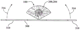
FIGS. 3A, 3B and 3C are top, side and front views, respectively, illustrating the steps of forming valve leaflets, according to one embodiment, wherein a leaflet tool covered by a bumper pad and release layer (shown in FIGS. 2A and 2B, respectively) is placed over the composite material for cutting and further assembly;
fig. 4 is a top view of a tripartite leaflet assembly prior to cutting excess leaflet material, according to one embodiment;
fig. 5A is a perspective view of a tri-leaflet assembly and base tool, according to one embodiment;
fig. 5B is a top view of a certain tri-leaflet assembly and base tool aligned and assembled to form a base tool assembly, according to one embodiment;
FIG. 6A is a plan expanded view of a stent frame or support structure according to one embodiment;
FIG. 6B is a plan view of a support structure covered with a polymer coating according to one embodiment;
figures 7A, 7B, and 7C are scanning electron micrographs of an expanded fluoropolymer film used to form valve leaflets according to one embodiment;
FIG. 8 is a perspective view of a valve assembly according to one embodiment;
FIGS. 9A and 9B are top views of the heart valve assembly of FIG. 8 in exemplary closed and open positions, respectively, according to one embodiment;
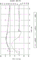
FIG. 10 is a map of measured output data from a heart flow pulse replicator system for measuring performance of a valve assembly manufactured according to one embodiment;
11A and 11B are a map and a data sheet, respectively, of the measured output from a high speed fatigue tester used to measure the performance of a valve assembly made in accordance with one embodiment;
12A and 12B are graphs of measured output from a heart flow pulse replicator system when testing a valve assembly according to an embodiment after 0 and 2.07 hundred million cycles, respectively;
FIGS. 13A and 13B are graphs of measured output from a heart flow pulse replicator system when testing a valve assembly made according to an embodiment, after 0.79 and 1.98 hundred million cycles, respectively;
FIG. 14 is a perspective view of a mandrel for use in manufacturing a heart valve assembly, according to one embodiment;
FIG. 15 is a perspective view of a valve frame for a heart valve according to one embodiment;
FIG. 16 is a perspective view of the valve frame of FIG. 15 nested with the mandrel of FIG. 14, according to one embodiment;
FIG. 17 is a perspective view of a molded valve according to one embodiment;
FIG. 18 is a perspective view of a molded valve according to one embodiment showing an attachment for enhancing adhesion between adjacent valve leaflets and a stem on a valve frame;
FIG. 19 is a perspective view of a valve frame according to one embodiment;
FIG. 20 is a perspective view of the valve stent of FIG. 19, the rods of the valve frame having all covered cushioning elements, according to one embodiment;
FIG. 21 is a perspective view of a mandrel formed by a stereolithography technique according to one embodiment;
FIG. 22 is a perspective view of the mounting of the cushioning element-encased valve frame assembly of FIG. 20 to the mandrel of FIG. 21, according to one embodiment; and
FIG. 23 is a perspective view of a valve according to one embodiment with its valve leaflets attached to and supported by the valve frame of FIG. 20 enclosing a cushioning element;
FIG. 24 is a perspective view of a valve frame according to one embodiment;
FIG. 25 is a perspective view of a valve frame with a cushioning layer according to one embodiment;
FIG. 26 is a perspective view of a mandrel according to one embodiment;
FIG. 27 is a perspective view of a valve assembly according to one embodiment;
FIG. 28 is a perspective view of a mandrel according to one embodiment;
FIG. 29 is a perspective view of a prosthetic valve according to one embodiment;
figure 30A is a scanning electron micrograph of a surface of a microporous polyethylene film used to form a valve leaflet according to one embodiment;
FIG. 30B is a scanning electron micrograph of a cross section of the microporous polyethylene film of FIG. 30B, according to one embodiment;
figure 31A is a scanning electron micrograph of a stretched microporous polyethylene film used to form a valve leaflet according to one embodiment;
FIG. 31B is a scanning electron micrograph of a cross section of the microporous polyethylene film of FIG. 31B, according to one embodiment;
FIG. 32A is an edge view of a compression bend test specimen that failed the compression bend test;
FIG. 32B is an edge view of a compression bend test specimen that passes the compression bend test;
FIG. 32C is an edge view of a compression bend test specimen that passes the compression bend test;
FIG. 33 is an edge view of a compression bend test specimen in a compression bend test fixture;
FIG. 34 is a perspective view of one embodiment prosthetic valve having leaflets comprising folded leaflet material;
fig. 35A is an edge view of a leaflet material having two folded portions;
fig. 35B is a top view of the leaflet material of fig. 35A;
fig. 35C is an edge view of the leaflet material of fig. 35A, wherein the leaflet material has been folded and smoothed over two folded portions, thus connecting the two folded portions to define a folded leaflet material;
fig. 35D is a top view of the folded leaflet material of fig. 35C;
FIG. 36 is a perspective view of a valve frame assembled on a mandrel during encapsulation with folded leaflet material;
fig. 37 is a top view of a folded leaflet material showing folded edges and a cut pattern defining a leaflet; and
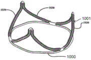
fig. 38 is a top view of a leaflet having a folded leaflet free edge.
Detailed description of the invention
Reference will now be made to the embodiments illustrated in the drawings and specific language will be used to describe the same. It will nevertheless be understood that no limitation of the scope of the invention is thereby intended, such alterations and further modifications in the illustrated method and apparatus, and such further applications of the principles of the invention as illustrated therein being contemplated as would normally occur to one skilled in the art to which the invention relates.
As used herein, "matrix tensile strength" refers to the tensile strength of a fluoropolymer sample under specified conditions. The porosity of the sample was calculated by multiplying the tensile strength by the ratio of the density of the polymer to the density of the specimen.
As used herein, the term "film" refers to a porous sheet of material comprising a single component (such as, but not limited to, an expanded fluoropolymer).
The term "composite material" as used herein refers to a combination of a film (such as, but not limited to, an expanded fluoropolymer) and an elastomer (such as, but not limited to, a fluoroelastomer). The elastomer can be imbibed into the porous structure of the membrane, coated on one or both sides of the membrane, or coated on the membrane in combination with imbibing the membrane.
The term "laminate" as used herein refers to a multilayer film, composite, or other material such as an elastomer, and combinations thereof.
The term "imbibe" as used herein refers to any method for at least partially filling a pore with a second material.
For porous membranes in which the pores are substantially filled with elastomer, the elastomer can be dissolved or degraded with a suitable solvent and rinsed away to measure the desired properties.
The term "elastomer" as used herein, defines a polymer or mixture of polymers that has the ability to stretch to at least 1.3 times its original length and to retract rapidly to approximately its original length after release. The term "elastomeric" is intended to describe a property whereby the polymer exhibits similar stretch and recovery properties to elastomers, but need not achieve the same level of stretch and/or recovery.
The term "thermoplastic" as used herein, defines a melt processable polymer. "thermosetting" polymers are defined herein as polymers that solidify or irreversibly "set" when cured, relative to thermoplastic polymers.
The terms "fibrils" and "fibers" are used interchangeably herein.
The term "synthetic polymer" as used herein refers to a polymer that is not derived from biological tissue.
The term "leaflet" as used herein in the context of a prosthetic valve refers to a component of a one-way valve in which the leaflets operate under the influence of a pressure differential to move between open and closed positions. In the open position, the leaflets allow blood to flow through the valve. In the closed position, the leaflets substantially block retrograde flow of blood through the valve. In embodiments comprising a plurality of leaflets, each leaflet cooperates with at least one adjacent leaflet to block backflow of blood. A leaflet according to embodiments herein, comprising one or more layers of a composite material.
The terms "frame" and "support structure" are used interchangeably to refer to a member to which the leaflets are attached or supported so as to be operable as a prosthetic valve. The support structure may be, but is not limited to, stents and catheters.
As used herein, "connected" refers to joined, coupled, attached, bonded, attached, or bonded, whether direct or indirect, and whether permanent or temporary.
As used herein, the terms "bonded" and "bonded together" refer to being permanently bonded together using any suitable method, without the use of additional materials to achieve bonding, such as, but not limited to, adhesives. One method for bonding the films together such that the ply bonds to an adjacent ply is, but is not limited to, sintering. Some degree of bonding also occurs when multiple plies are calendered together and when multiple plies in direct contact expand.
As used herein, "delamination" refers to splitting caused by bending.
As used herein, the term "sintering" refers to a process of heating a material to a temperature at or above the crystalline melting temperature of the material, thereby constituting the material.
The term "porous" as used herein means having pores.
As used herein, the terms "microporous" and "microporous structure" refer to fibers and pores having small size. Specifically, the fibers in the film should have an average diameter of less than 1 micron, the film should have an average flow pore size of less than 5 microns, or the film should have a mean flow pore size of greater than 4.0m2Specific surface area of/cc. Any of these characterizations is sufficient to account for microwells.
As used herein, the term "impermeable" refers to a material that exhibits a mass increase of less than about 10% in the performance of the Liquid collection test (Liquid PickupTest) described below. Alternatively, "impermeable" means having a gurley number greater than 1000 seconds as described in the gas permeation test. Each characterization is sufficient to account for impermeability.
As used herein, the term "monolayer" refers to a structure comprised of a single ply of a sheet material. One example of a single layer is a single ply of a sheet of expanded PTFE. The expanded PTFE may or may not then be heated to a temperature at or above the crystalline melting temperature of the PTFE. Another example of a monolayer is a single ply of a sheet of expanded polyethylene.
As used herein, the term "coherent single layer" refers to a structure made up of at least one ply (i.e., one ply or two or more plies) of the same material bonded together such that a ply is bonded to an adjacent ply and is made up of only that material except for impurities that are typically bonded thereto. The "same material" may include, for example, various forms of PTFE described above or below. Further, for example, "the same material" may include ePTFE materials having different microstructures and/or fibril orientations in a coherent single layer. Likewise, for example, "the same material" may include porous polyethylene films having different microstructures in a single coherent layer.
The coherent single layer is not a woven, knitted, felt or foam. A coherent single layer includes, but is not limited to, a material that is stretched to create or create pores. As used herein, a coherent single layer defines a fiber or fibril structure in which the lengths of the discontinuous fibers or fibrils are not intertwined to form the material described above. Alternatively, as shown in fig. 7A, 7B and 7C, fig. 30A and 30B, and fig. 31A and 31B, a large number of small diameter fibrils are interconnected to form a coherent single layer. The coherent single layer includes fibers defining spaces between the fibers.
An example of a coherent single layer is a single layer. Another example of a coherent single layer is a stack of two or more plies of PTFE extrudate, which may or may not contain extrusion aids, may or may not be stretched, may or may not be calendered, wherein the stack is expanded, and then may or may not be heated to a temperature at or above the crystalline melting temperature of the PTFE to provide dimensional stability and adhesion, or to further bond the plies together, and so forth. As a result of these process steps, the plies of the final article are bonded together at their interfaces, producing a coherent single layer. Another example of a coherent single layer is a stack of two or more plies of expanded PTFE film that are then heated to a temperature at or above the crystalline melting temperature of PTFE to provide dimensional stability and adhesion, or to further bond the plies together, or the like. Other materials, including but not limited to polyethylene and polypropylene, may be used to form a coherent single layer.
As used herein, the term "impermeable coherent single layer" refers to a porous coherent single layer wherein the pores comprise an elastomer rendering the coherent single layer impermeable.
As used herein, the term "bend failure" refers to any separation of the material structure, for example: splitting occurs in the performance of the compression bending test described below.
The present invention addresses a long felt need in the industry to develop materials that can meet the durability and biocompatibility requirements for high-cycle curved graft applications, such as in heart valve leaflets. It has been shown that heart valve leaflets formed of porous fluoropolymer material, or, more specifically, ePTFE that is free of elastomer, suffer from stiffening during high cycle bending tests and implantation in animals.
In one embodiment, which will be described in further detail below, the flexural durability of porous polymeric heart valve leaflets can be significantly improved by incorporating a relatively high percentage of an elastomer with relatively low strength in the pores. Optionally, additional layers of elastomer may be added between the composite layers. Surprisingly, in certain embodiments, the porous polymer membrane is imbibed with an elastomer, the presence of which increases the overall thickness of the leaflet, but the increased thickness of the polymeric article due to the addition of the elastomer does not interfere or reduce bending durability. Furthermore, when the elastomer reaches a minimum percentage by weight, we have found that the performance of the fluoropolymer article becomes better as the percentage of elastomer increases, resulting in a significantly improved cycle life, capable of cycling in vitro for over 4 million cycles, and showing no evidence of calcification under certain controlled laboratory conditions.
A material according to one embodiment includes a composite material comprising an expanded fluoropolymer membrane and an elastomeric material. Those skilled in the art will appreciate that various types of fluoropolymer films and various types of elastomeric materials may be combined within the spirit of the present invention. It will also be appreciated by those skilled in the art that the elastomeric materials described above may include a variety of elastomers, various types of non-elastomeric components such as inorganic fillers, therapeutic agents, radio-opaque markers, and the like within the spirit of the present invention.
In some embodiments, the above-described composite material comprises an expanded fluoropolymer material made from a porous ePTFE membrane, as generally described in U.S. patent No. 7306729. In other embodiments, the composite material comprises a polyethylene material made from a porous polyethylene film.
The expandable fluoropolymer used to form the expanded fluoropolymer material described in some embodiments may include PTFE homopolymer. In further embodiments, blends of PTFE, expandable modified PTFE and/or expanded copolymers of PTFE may be employed. Non-limiting examples of suitable fluoropolymer materials are described in, for example, U.S. patent No. 5708044 to blake (Branca), U.S. patent No. 6541589 to bailie (Baillie), U.S. patent No. 7531611 to sabola (Sabol), etc., U.S. patent application No. 11/906877 to Ford (Ford), and U.S. patent application No. 12/410050 to Xu (Xu), etc.
The expanded fluoropolymer according to some embodiments may include any suitable microstructure to achieve desired leaflet properties. In one embodiment, the expanded fluoropolymer described above may comprise a microstructure of nodes interconnected by fibrils, as described by Gore (Gore) in U.S. patent No. 3953566. In one embodiment, the microstructure of the expanded fluoropolymer film described above comprises nodes interconnected by fibrils, as shown in the sem picture of fig. 7A. The fibrils extend from the nodes in multiple directions and thus the film is generally of a uniform structure. Films having this microstructure have a ratio of matrix tensile strengths in two orthogonal directions of less than about 2, and possibly less than about 1.5.
In another embodiment, the microstructure of the expanded fluoropolymer film described above is substantially fibril only, as shown, for example, in fig. 7B and 7C, as generally described in Bacino (Bacino) in U.S. patent No. 7306729. FIG. 7C, at a higher magnification than FIG. 7B, is also a scanning electron micrograph of the expanded fluoropolymer film and more clearly shows the substantially fibril-only homogeneous structure. The expanded fluoropolymer film containing substantially only fibrils, as shown in FIGS. 7B and 7C, can have a high surface area, e.g., greater than about 20m2A/g or greater than about 25m2A/g, and in some embodiments can provide a highly balanced strength material having a product of matrix tensile strength in two orthogonal directions of at least 1.5 x 10⁵MPa2And/or the ratio of the tensile strengths of the matrix in two orthogonal directions is less than about 2, and possibly less than about 1.5. According to some embodiments, it is contemplated that the expanded fluoropolymer film has a mean flow pore size of less than about 5 microns, less than about 1 micron, and less than about 0.10 microns.
The expanded fluoropolymer according to some embodiments can be tailored to have any suitable thickness and quality to achieve the desired leaflet properties. In some cases, it may be desirable to use very thin expanded fluoropolymer films having a thickness of less than about 1.0 micron. In other embodiments, it may be desirable to use expanded fluoropolymer films having a thickness greater than about 0.1 microns and less than about 20 microns. The specific mass of the expanded fluoropolymer film may be less than about 1g/m2To greater than about 50g/m2。
Based on PTFE, about 2.2g/cm3The substrate tensile strength of a film comprising an expanded fluoropolymer according to one embodiment may range from about 50MPa to about 400MPa or greater.
Other materials may be added in the pores of the membrane or inside the membrane material or between the membrane layers to enhance the desired leaflet properties. A composite material according to one embodiment may include an expanded fluoropolymer film having a thickness ranging from about 500 μm to less than about 0.3 μm.
Embodiments of expanded fluoropolymer membranes incorporating elastomers provide desirable performance characteristics for high-cycle curved implant applications, such as heart valve leaflets, in at least several relatively significant respects. For example, the addition of the elastomer improves the fatigue properties of the leaflets because the stiffening observed with ePTFE material alone is eliminated or reduced. Furthermore, it reduces the possibility of permanent set deformations of the material, such as wrinkles or creases, which could impair the performance of the leaflets. In one embodiment, the elastomer occupies substantially all of the pore volume or space in the pore structure of the expanded fluoropolymer membrane. In another embodiment, the elastomer is present in substantially all of the pores of at least one fluoropolymer layer. Because the elastomer fills the void volume or is present in substantially all of the pores, the incorporation of foreign matter into the composite material space is reduced, which is undesirable. One example of such foreign material is calcium. If calcium is incorporated into the composite material, for example, when used in the leaflets of a heart valve, mechanical damage can occur in the circulation and thus result in the formation of pores in the leaflets and a reduction in their hemodynamic performance.
In one embodiment, the elastomer bonded to the ePTFE is a thermoplastic copolymer of Tetrafluoroethylene (TFE) and perfluoromethyl vinyl ether (PMVE), as described in U.S. patent No. 7462675. As noted above, the above-described elastomers are combined with expanded fluoropolymer films such that the elastomers occupy substantially all of the void space or pores within the expanded fluoropolymer film. The pores of the expanded fluoropolymer membrane may be filled with elastomer in a variety of ways. In one embodiment, a method of filling pores of an expanded fluoropolymer membrane comprises the steps of: the elastomer is dissolved with a suitable solvent to produce a solution of suitable viscosity and surface tension suitable for partial or complete flow into the pores of the expanded fluoropolymer membrane, and the solvent is allowed to evaporate, leaving the filler in the pores.
In another embodiment, a method of filling pores of an expanded fluoropolymer membrane comprises the steps of: the filler is delivered by dispersion, partially or completely filling the pores of the expanded fluoropolymer film.
In another embodiment, a method of filling pores of an expanded fluoropolymer membrane comprises the steps of: the porous expanded fluoropolymer membrane is contacted with the elastomeric sheet under conditions of heat and/or pressure that cause the elastomer to flow into the pores of the expanded fluoropolymer membrane.
In another embodiment, a method of filling pores of an expanded fluoropolymer membrane comprises the steps of: the pores are first filled with a prepolymer of the elastomer and the elastomer is then at least partially cured, thereby polymerizing the elastomer in the pores of the expanded fluoropolymer film.
Leaflets made of fluoropolymer material or ePTFE generally perform better as the percentage of elastomer increases after the weight percentage of elastomer reaches a minimum, resulting in significantly longer cycle life. In one embodiment, the elastomer combined with the ePTFE is a thermoplastic copolymer of tetrafluoroethylene and perfluoromethyl vinyl ether, as described in U.S. patent No. 7462675, and others known to those skilled in the art. For example, in another embodiment shown in example 1, the leaflets are formed from a composite material in which the elastomer is 53% by weight of the ePTFE and subjected to a cycling test. After about 2 hundred million test cycles, some sclerosis was observed, but only minor effects on hemodynamics were observed. When the weight percent of elastomer was increased to about 83 weight percent, no hardening and no negative changes in hemodynamics were observed at about 2 hundred million cycles as described in the example 2 embodiment. In contrast, leaflets made of non-composite material, i.e., all ePTFE without elastomer, had a very significant severe stiffening phenomenon at 4 million test cycles as described in comparative example B. As demonstrated by these examples, the durability of porous fluoropolymer films can be significantly improved by incorporating a relatively high percentage of an elastomer having a relatively low strength into the pores of the fluoropolymer film. The high material strength of the fluoropolymer film allows for a particular construction to be very thin.
Other biocompatible polymers that may be suitable include, but are not limited to, the following groups: urethanes (urethanes), silicones (organopolysiloxanes), siloxane-urethane copolymers, styrene/isobutylene copolymers, polyisobutylene, ethylene-vinyl acetate copolymers, polyester copolymers, nylon copolymers, fluorinated hydrocarbon polymers and copolymers, or mixtures of the foregoing polymers.
In addition to expanded fluoropolymers, other biocompatible synthetic polymers may also be suitable for use as porous membranes. As described below, embodiments including microporous polyethylene are provided as biocompatible polymers suitable for a particular purpose.
One embodiment of the microporous polyethylene film comprises a sheet of material comprising substantially all fibers having a diameter of less than about 1 micron. In another embodiment, the microporous polyethylene film comprises a sheet of nonwoven material comprising substantially all fibers having a diameter of less than about 1 micron. In some cases, it may be desirable to use very thin microporous polyethylene films having a thickness of less than about 10.0 microns. In other embodiments, it may be desirable to use microporous polyethylene films having a thickness of less than about 0.6 microns.
It is to be understood that the structure of the microporous membranes disclosed in the embodiments described herein can be distinguished from other structures such as fabrics, knits, and filament windings by comparing the specific surface areas of the materials. Some embodiments of the microporous membranes described herein have a specific surface area greater than about 4.0m2And/cc. Microporous membranes according to other embodiments described herein have a specific surface area greater than about 10.0m2And/cc. Some embodiments described herein demonstrate specific surface areas greater than about 4.0m when used as leaflet materials2A/cc to greater than about 60m2The/cc membrane at least significantly improves, but is not limited to, the durability and longevity of heart valves.
It is to be understood that microporous membranes disclosed in some embodiments described herein may be distinguished from other structures such as fabrics, knits, and filament windings by comparing the fiber diameters of the materials as an alternative. Some embodiments of the microporous membranes described herein contain a majority of the fibers having a diameter less than about 1 micron. Other embodiments of the microporous membranes described herein contain fibers having a majority of diameters less than about 0.1 micron. Some embodiments described herein recognize that when used as leaflet material, a film containing fibers mostly less than about 1 micron to more than less than about 0.1 micron at least significantly improves, but is not limited to improving, the durability and longevity of heart valves.
The microporous polymer film of some embodiments can include any suitable microstructure and polymer to achieve desired leaflet properties. In some embodiments, the microporous polymer film is porous polyethylene having a microstructure of substantially only fibers, such as the material included for example 4 shown in fig. 30A and 30B and the material included for example 5 shown in fig. 31A and 31B. Fig. 30 shows a substantially uniform microstructure of a porous polyethylene film having substantially only fibers having a diameter of less than about 1 micron. The porous polyethylene film had a thickness of 0.010 mm, a porosity of 31.7% and a mass/area of 6.42g/m2And a specific surface area of 28.7m2/cc。
Fig. 31A and 31B are surface and cross-sectional views, respectively, of the same porous polyethylene film shown in fig. 30A and 30B (surface and cross-sectional views, respectively), stretched according to the method described in example 5 below. The stretched polyethylene film retains a substantially uniform microstructure having substantially only fibers having diameters less than about 1 micron. The stretched polyethylene film had a thickness of 0.006 mm, a porosity of 44.3%, and a mass/area of 3.14g/m2And a specific surface area of 18.3m2And/cc. According to some embodiments, microporous polyethylene films are contemplated having a mean flow pore size of less than about 5 microns, less than about 1 micron, and less than about 0.10 microns.
In addition to expanded fluoropolymers, other biocompatible synthetic polymers, such as, but not limited to, expanded polymeric films, are also suitable for use as porous films. As described below, embodiments including microporous polyethylene are provided as biocompatible polymers suitable for a particular purpose.
According to some embodiments, a prosthetic valve leaflet comprises a single layer of a porous synthetic polymer, i.e., a coherent single layer is porous, wherein the pores comprise an elastomer such that the coherent single layer is impermeable, thereby defining the leaflet material from which the leaflet is made. The leaflet material comprising a coherent single layer exhibits resistance to delamination as indicated in a compression bend test.
According to other embodiments, the prosthetic valve leaflet comprises at least one coherent single layer that is porous, wherein the pores contain an elastomer such that the at least one coherent single layer is impermeable.
According to other embodiments, a prosthetic valve leaflet comprises a plurality of porous coherent single layers, wherein the pores contain an elastomer such that the plurality of coherent single layers are impermeable and the leaflet is thereby impermeable. The plurality of coherent single layers are joined together via the elastomer between them and form a laminate of the plurality of coherent single layers. The plurality of coherent single layer laminates define leaflet material from which the leaflets can be fabricated.
It is to be understood that the leaflet material provided in the embodiments described herein can be formed into leaflets to provide a structure that functions as an artificial heart. The leaflets may be further attached to the frame by any suitable means, including stitching, adhesives, clamps, and other mechanical connectors. According to one embodiment, the frame is selectively diameter-adjustable for intravascular delivery and deployment at a treatment site.
According to some embodiments, a prosthetic valve is provided that includes a frame and leaflets connected to the frame. The leaflet comprises only one coherent single layer and an elastomer. The coherent single layer has a porous structure. The elastomer is present in the pores such that the coherent single layer is impermeable. According to some embodiments, the coherent single layer comprises a single layer. In other words, the coherent single layer comprises a single ply of a porous synthetic polymer film.
In other embodiments, the coherent single layer comprises a plurality of plies of porous synthetic polymer film bonded together from the same material, consisting essentially of that material only. In other embodiments, the coherent single layer comprises a plurality of plies of expanded synthetic polymer film bonded together by the same material, consisting essentially of that material only. According to other embodiments, the coherent single layer comprises a sintered stack of multiple plies of ePTFE membrane. According to some embodiments, the synthetic polymer films are porous prior to being placed in a stacked configuration and bonded together by any suitable means without the use of additional materials. According to some embodiments, the ePTFE membranes are expanded prior to placement in the stacked configuration and heated above the crystalline melting temperature of the PTFE, thereby bonding the multiple plies of ePTFE membranes together. According to other embodiments, plies of porous or non-porous synthetic polymer film are placed in a stacked configuration, then made porous or more porous (e.g., made larger), and then bonded together by any suitable means without the use of additional materials. According to other embodiments, the plies of PTFE extruded sheet are placed in a stacked configuration, then expanded, and then heated above the crystalline melting temperature of PTFE to bond the expanded PTFE extruded sheets together.
According to some embodiments, the pore size of the coherent single layer is less than 5 microns.
According to some embodiments, the fiber diameter of the coherent single layer is less than about 1 micron.
According to some embodiments, the leaflet comprises only one coherent single layer and an elastomer present in the pores of the coherent single layer, wherein the leaflet comprises at least 10 wt.% elastomer.
According to some embodiments, the leaflet has a tensile strength in at least two orthogonal directions greater than 35 MPa. According to some embodiments herein, the ratio of the tensile strength of the leaflet in the strongest direction to the tensile strength in a direction orthogonal to the strongest direction is less than about 2.
According to some embodiments, the leaflet passes the compression bend test described herein. The compression bend test is an evaluation of the resistance of a material to cohesive failure (cohesivefailure) when the material is held in a high stress state for an extended period of time. Fig. 32A is an edge view of a compression bend test sample 36 that failed the compression bend test. Fig. 32B-32C show edge views of a compression bend test sample 36 that passed the compression bend test. When the compressive bending test specimen 36 fails in the compressive bending test, at least one crack 39 is formed in the thickness of the compressive bending test specimen 36. In some embodiments of a coherent single layer comprising a single layer of a synthetic polymer film, the single layer may or may not have cracks formed therein. In some embodiments of a coherent single layer comprising a plurality of plies of a porous synthetic polymer film, a slit may or may not be formed between two plies of the synthetic polymer film. The compression bend test specimen 36 may exhibit wrinkling or bulging 37 at the bend 38, but this is not considered a failure condition due to failure of the compression bend test, except with one or more cracks 39.
According to some embodiments, the leaflet has a compression set in the compression set test described herein of less than 10%. The compression set test is an evaluation of the ability of a material to resist changes in thickness after the material is placed under a compressive load and allowed to recover. A low compression set rate, for example, indirectly indicates that the pores of the porous material contain elastomer. The addition of an elastomer to the porous material reduces the rate of compression set.
A light transmittance test was performed to identify the material before and after the elastomer was introduced into the porous structure. The leaflet material comprising a coherent single layer and an elastomer has a light transmission of at least 60%. According to some embodiments, the leaflet has a light transmittance of at least 80% in the light transmittance test described herein. The light transmittance test evaluates the ability of light to transmit through the sample without scattering. High light transmittance indicates that the pores of the porous material are sufficiently filled with elastomer to render the porous material impermeable.
The above-described coherent single-layer structure can be constructed in any one of the following three ways.
1. A porous single ply of a porous synthetic polymer film, in other words a monolayer, is built up.
2. Multiple plies of porous synthetic polymer film of the same material are stacked and then bonded together using any suitable means without the use of additional materials.
3. Multiple plies of porous or non-porous synthetic polymer film are stacked, made porous or more porous (e.g., made larger), and bonded together using any suitable means without the use of additional materials.
As an example of an embodiment of a coherent single layer, particularly for a PTFE membrane, three of the above-described coherent single layer structures are constructed as described below. Although PTFE is described below, other materials, including but not limited to polyethylene and polypropylene, may be used to form the coherent monolayer as described in example 9.
According to one embodiment, the leaflet comprises only one porous ePTFE membrane and has an elastomer in the pores, rendering said ePTFE membrane impermeable, thus rendering said leaflet impermeable. Only one ePTFE film is referred to herein as a monolayer.
According to one embodiment, the elastomer present in the pores may be crosslinked.
According to one embodiment, the leaflets comprise a porous monolayer and have an elastomer in the pores, so that the leaflets are impermeable. According to one embodiment, the transmission of the leaflet may be at least 60%. A light transmission of at least 60% ensures that there is sufficient elastomer in the pores to render the monolayer impermeable.
The thickness of the leaflets constructed from a single layer may be about 150 microns or less than 150 microns.
According to another embodiment, the leaflet comprises a porous ePTFE membrane comprising a plurality of plies, wherein the plies have been expanded prior to being disposed in a stacked configuration and heated to a temperature above the crystalline melting temperature of PTFE, thereby bonding the plies to produce a porous coherent single layer. The leaflets also comprise an elastomer in the apertures of the coherent single layer such that the coherent single layer is impermeable, thus rendering the leaflets impermeable.
According to one embodiment, the leaflet comprises a plurality of plies of porous ePTFE membrane treated as above, such that the plies are bonded to produce a porous coherent single layer. The leaflet further comprises an elastomer in the aperture, whereby the leaflet has a light transmittance of at least 60%. A light transmission of at least 60% ensures that there is sufficient elastomer in the pores to render the coherent single layer impermeable, and thus the leaflets impermeable.
According to one embodiment, the elastomer present in the pores may be crosslinked.
The leaflet comprising a coherent single layer as described above may have a thickness of about 150 microns or less than 150 microns.
According to another embodiment, the leaflet comprises a plurality of plies of PTFE extruded sheet, which are stacked and then expanded to make the PTFE membrane porous or more porous, and after expanding it, heated to a temperature at or above the crystalline melting temperature of PTFE to further bond the plies to produce a coherent single layer that is porous. The leaflet also includes an elastomer in the aperture of the coherent single layer such that the coherent single layer is impermeable.
According to one embodiment, the elastomer present in the pores may be crosslinked.
According to one embodiment, the leaflet comprises a plurality of plies of PTFE film treated as above, such that the plies are bonded to produce a porous coherent single layer. The leaflet further comprises an elastomer in the aperture, whereby the leaflet has a light transmittance of at least 60%. A light transmission of at least 60% ensures that there is sufficient elastomer in the pores to render the coherent single layer impermeable.
The thickness of the leaflets constructed from coherent single layers as described above may be about 150 microns or less than 150 microns.
Fig. 34 is a perspective view of one embodiment of a prosthetic valve 70 having leaflets 60 comprising folded leaflet material. Each leaflet 60 has a leaflet free edge 62 defined by the folded edge 54, wherein the leaflet contains leaflet material that has been folded. In contrast to the leaflet free edge 62 defined by the cut edge formed in the leaflet material 50, the folded edge 54 does not expose an edge severed across one or more layers and/or plies of the leaflet material 50.
Fig. 35A and 35B are an edge view and a top view, respectively, of a leaflet material 50, the leaflet material 50 having two folded portions 52a, 52B, the two folded portions 52a, 52B being foldable along a fold line 53 in a direction generally indicated by arrow 59. Fig. 35C and 35D are an edge view and a top view, respectively, of the leaflet material 50 of fig. 35A, the leaflet material 50 having been folded over two folded portions 52a, 52b, joining the two folded portions 52a, 52b, thereby defining a folded leaflet material 50 a. The resulting folded leaflet material 50a defines a folded edge 54 and an unfolded edge 55 opposite the folded edge 54. When assembled into a prosthetic valve 70, the folded edges 54 will define folded leaflet free edges 64 of the leaflets 60, as shown in fig. 34. In other words, in this embodiment, the illustrated leaflet free edge 62 is a folded leaflet free edge 64.
Fig. 36 is a perspective view of a valve frame 1000 according to an embodiment of a method of making the prosthetic valve 70 of fig. 34 having folded leaflet free edges 64, the valve frame 1000 having been mounted on a mandrel 1200 and in the process of being coated with folded leaflet material 50 a. The valve frame 1000 is slid onto the mandrel 1200. The folded leaflet material 50a wraps around and is attached to the valve frame outer surface 1002 of the valve frame 1000. The folded edge 54 faces away from the frame base 1103 of the valve frame 1000, thereby defining a folded leaflet free edge 64. Figure 34 is a perspective view of a prosthetic valve 70 showing the leaflet free edges 64 folded, made according to the methods described above.
According to some other embodiments, the folded leaflet material 50a can be attached to the valve frame inner surface of the valve frame 1000 instead of the valve frame outer surface. According to another embodiment, the leaflet material 50 is wrapped around the mandrel 1200 and the valve frame 1000 is slid over a portion of the leaflet material 50, such as the folded portion 52 a. A portion of the leaflet material 50 extends across the valve frame, such as folded portion 52b, and is rolled back on the outer surface of the frame to define a folded edge 54. The leaflet material 50 is attached to the valve frame 1000 and to itself to define a folded leaflet material 50a and a folded leaflet free edge 64.
According to other embodiments, individual leaflets 60 can be cut from the folded leaflet material 50 a. Fig. 37 is a top view of a folded leaflet material 50a showing folded edges 54 and a cut pattern 58, the cut pattern 58 defining a leaflet 60. Fig. 38 is a top view of a leaflet 60 having a folded leaflet free edge 64 cut from the folded leaflet material 50a along the cutting pattern 58. The folded leaflet material 50a is cut along a cutting pattern 58 to form cut lines 57 of the leaflets 60. The portion of the leaflet 60 adjacent the cut line 57 is the portion that can then be attached to a structure, such as, but not limited to, a valve frame 1000 or a catheter. The portion of the folded edge 54 of the folded leaflet material 50a that is not directly connected to the structure will define the folded leaflet free edge 64.
According to some embodiments, the leaflet material 50 of the leaflet 60 comprising the folded leaflet free edge 64 can comprise a composite material comprising one or more films, laminates, and/or coherent single layers.
The embodiments are further illustrated by the non-limiting examples provided below.
Example 1
According to one embodiment, the heart valve leaflets are formed of a composite material comprising an expanded fluoropolymer membrane and an elastomeric material and attached to a metallic balloon expandable stent, as described in embodiments below.
A thick sacrificial tool bumper or buffer layer is formed by repeated folding of an ePTFE layer, conformal to four layers. The ePTFE layer is about 5cm (2 ") wide and about 0.5 mm (0.02") thick and has a high degree of compressibility to form a cushion. Referring to fig. 1 and 2, the cushion 200 is then stretched over a leaflet tool (fig. 2), generally designated 100. Leaflet tool 100 described above has a leaflet section 102, a main body section 104, and a bottom end 106. Leaflet section 102 of leaflet tool 100 described above generally has an arcuate, convex shaped end surface 103. The above-described cushion 200 stretches and smoothes over end surface 103 of leaflet section 102 of leaflet tool 100 by compressing leaflet tool 100 in the direction shown by the arrow (fig. 2A). The peripheral edge 202 of the cushion 200 is stretched over the bottom end 106 of the leaflet tool 100 and wrapped around to secure the cushion 200 in place (fig. 2B).
Referring to fig. 2B, release layer 204 is then stretched over leaflet section 102 of leaflet tool 100, which leaflet section 102 has been covered by bumper pad 200 in a previous step. In one embodiment, the release layer 204 is made of substantially non-porous ePTFE and a layer of Fluorinated Ethylene Propylene (FEP) is deposited along its outer surface or side. The release layer 204 is stretched over the leaflet tool 100 such that the FEP layer faces the bumper 200 and the substantially non-porous ePTFE faces outward or away from the bumper 200. The release layer is approximately 25 microns thick and has a length and width sufficient to allow the release layer 204 to cover the end 106 of the leaflet tool 100 when extended. Similar to the previous step of stretching the cushion 200, the peripheral edge 206 of the release layer 204 is pulled toward the bottom end 106 of the leaflet tool 100 and wrapped around the bottom end 106 of the leaflet tool 100 to hold or secure the release layer 204 in place. The FEP layer of the release layer 204 is then locally melted and thus fixed to the crash pad 200, and an electric iron may be used if necessary.
Repeating the processes of step 1) and step 2) to prepare three leaflet tools, each having a buffer pad covered by a release layer.
According to one embodiment, the leaflet material is formed from a composite material comprising an ePTFE membrane imbibed with a fluoroelastomer. A piece of the above composite material about 10 cm wide was wrapped over a circular mandrel to form a tube. The composite material comprises three layers: two outer layers of ePTFE and an inner layer of fluoroelastomer disposed therebetween. The ePTFE membranes described above were made according to the general teachings described in us patent No. 7306729. The above-described fluoroelastomers are made according to the general teachings described in U.S. patent No. 7462675. Other fluoroelastomers may be suitable, as described in U.S. patent publication No. 2004/0024448.
The ePTFE membrane had the following properties: thickness of about 15 microns, MTS of about 400MPa in the highest strength direction, MTS strength of about 250MPa in the orthogonal direction, density of about 0.34g/cm3IBP is about 660 KPa.
The copolymer consists essentially of: about 65 to 70 weight percent perfluoromethyl vinyl ether and complementary about 35 to 30 weight percent tetrafluoroethylene.
The weight percent of fluoroelastomer relative to ePTFE was about 53%.
The above multilayer composite material has the following properties: a thickness of about 40 microns and a density of about 1.2g/cm3The breaking force/maximum strength direction width was about 0.953kg/cm, the tensile strength in the maximum strength direction was about 23.5MPa (3400psi), the breaking force/orthogonal direction width was about 0.87kg/cm, and the orthogonal direction was perpendicular to the direction of the tensile strengthTensile strength in the direction of about 21.4MPa (3100psi), IPA bubble point greater than about 12.3MPa, Gurley Number greater than about 1800 seconds, and mass/area of about 14g/m2。
The following test methods were used to characterize the ePTFE layers and the multilayer composites.
The thickness was measured using a Mitsubishi Absolute caliper (Mutitoyo Snap Gauge Absolute) manufactured in Japan, which had a diameter (diameter root) of 12.7 mm (0.50"), a model ID-C112E, and a serial number of 10299. The density was measured by weight/volume calculation using a mettler Analytical balance PM400(Analytical balance PM400) available from new jersey, usa. The breaking force and tensile strength were measured using an Instron Model #5500R Norwood from massachusetts, usa under the following test conditions: the load cell was 50kg, gauge length 25.4 cm, crosshead speed 25 mm/min (strain rate 100% per minute) and with a flat jaw. The IPA bubble point was measured using an IPA bubble point tester available from salt lake City, Utah, USA, specifically, Pressure regulated Industrial Data System Model LG-APOK (Pressure Regulator Industrial Data Systems Model LG-APOK), and the Pressure increase rate was 1.38KPa/s (0.2psi/s), and the test area was 3.14cm2. The Gurley Number (Gurley Number) is determined to be 100cm3Air flowed 6.45cm at 124mm water pressure2The time taken for the sample in seconds was measured using a Gurley Tester Model #4110 (Gurley Tester, Model #4110) from troley, new york, usa.
Unless otherwise stated, these test methods were used to generate the data for the following examples.
A multi-layer composite comprising two outer layers of ePTFE and an inner layer of fluoroelastomer disposed therebetween was wrapped onto a mandrel having a diameter of about 28 millimeters (1.1 ") such that the direction of higher strength of the membrane would be oriented along the axial direction of the mandrel. In one embodiment, four layers of the composite material are wrapped onto the mandrel in a non-helical, substantially circumferential manner. The composite material has a slight tackiness which allows the material to adhere to itself. While the composite is still on the mandrel, the composite is cut longitudinally substantially along the long axis of the mandrel to form sheets of about 10 centimeters (4 ") by about 90 millimeters (3.5").
The resulting sheet of leaflet material (or composite material from step 4) is then cut and coated onto a leaflet tool 100, the leaflet tool 100 having a cushion pad 200 covered by a release layer 204. More specifically, as shown in fig. 3A-3C, leaflet material 300 is disposed onto a flat cutting surface. The leaflet tool 100 with the bumper pad 200 and release layer 204 is approximately aligned with the leaflet material 300 in the position shown. Four incisions 302, 304, 306, and 308 are then made in the leaflet material 300 with a razor blade. One pair of slits 302, 304 extend from one side of leaflet tool 100 and terminate at one side edge 300a of leaflet material 300, and the other pair of slits 306, 308 extend from the opposite side of leaflet tool 100 and terminate at the opposite side edge 300b of leaflet material 300. Incisions 302, 304, 306, and 308 are separated by leaflet section 102 of leaflet tool 100. The incisions 302, 304, 306, and 308 do not protrude below the leaflet tool 100. It should be understood that the width of each slit is not shown to scale. The cuts 302, 304, 306, and 308 in the leaflet material 300 result in the formation of a folded portion 310, a pair of straps 312 and 314, and excess leaflet material 315. The folded portion 310 is then folded in the direction generally indicated by arrow 316 in fig. 3C and smoothed over the leaflet tool 100, which leaflet tool 100 has been covered by the bumper pad 200 and release layer 204 in the previous step.
A base tool is then provided having a cavity that engages the end surface of the leaflet tool in the tri-leaflet assembly and excess leaflet area can be trimmed to form 3 leaflets. Referring to fig. 5A, the base means is generally designated 500 and extends longitudinally from one end 501 to an opposite bottom end 503. Three cavities 502, 504 and 506 are formed at the end 501 of the base tool 500. Each cavity 502, 504, and 506 is formed to matingly or nestingly receive end surface 103 of one of the three leaflet assemblies 402, 404, and 406. Three radially extending elements 508, 510 and 512 extend outwardly from the end of the base tool 500. Each element 508, 510, and 512 is disposed between a pair of adjacent cavities 502, 504, and 506.
The base tool 500 is then prepared with a compression pad and release layer (not shown) similar to how the leaflet tool is prepared with a cushion and release layer in steps 1 and 2. The compression pads and release layer described above are also stretched and secured over the base tool 500 to form a base tool assembly, similar to that described for each leaflet tool in steps 1 and 2.
Referring to fig. 5B, the base tool assembly (only base tool 500 is shown and compression pads and release layer omitted for ease of illustration) and the tri-leaflet tool assembly (generally 400) described above are axially aligned such that the end surface (not shown) of each leaflet tool 100 is disposed in one of the cavities (not shown) of the end 501 of the base tool (generally 500) to form a combined tool assembly.
Then, a metallic balloon expandable stent is manufactured. A 316 stainless steel tube having a wall thickness of about 0.5 millimeters (0.020 ") and a diameter of about 2.5 centimeters (1.0") was laser cut. The stainless steel tube is pattern cut to form an annular cut stent frame or support structure (generally designated 600), an exemplary plan expanded view of which is shown in fig. 6 a. The support structure 600 includes a plurality of closed small-pore chambers 602, a plurality of closed large-pore chambers 604, and a plurality of closed small-pore chambers 606. It should be noted that one of the plurality of closed leaflet orifices 606 in fig. 6A appears like an open orifice due to the plan view. The closed small-pore chambers 602, closed large-pore chambers 604, and closed small-pore chambers 606 are generally arranged in rows to form the annular support structure 600.
The polymeric material is bonded to the laser cut stent framework. First, a sacrificial compressed layer, an ePTFE membrane, was wrapped without overlap over a mandrel (not shown) having a diameter of about 2.5 centimeters (1.0 "). The sacrificial compressed layer ePTFE described above has a membrane thickness of about 0.5 millimeters (0.02 ") and a width of about 10 centimeters (4"), and it is compliant and compressible to provide a soft sacrificial compressed layer.
Four layers of substantially non-porous ePTFE membrane were then wrapped over the mandrel, on top of the compressed layer of membrane. The substantially non-porous ePTFE described above has a film thickness of about 25 microns (0.001 ") and a width of about 10 centimeters (4"), and contains an FEP layer on one side. The FEP layer faces away from the mandrel when wrapped with the substantially non-porous ePTFE film described above. The substantially non-porous ePTFE membrane described above has the properties of the release layer described in step 2) above.
Type 1 (us material test standard D3368, ASTM D3368) FEP films are made using a melt extrusion and drawing process. An additional 10 layers of FEP film of type 1(ASTM D3368) above, are added to the mandrel which has been previously coated with a compression layer film in step 10 and four layers of substantially non-porous ePTFE film in step 11. The type 1(astm d3368) FEP film described above has a thickness of about 40 microns (0.0016 ") and a width of about 7.7 centimeters (3").
The coated mandrel was then placed in an air convection oven for heat treatment, held at about 320 ℃ for about 5 minutes and cooled.
The support structure (600 labeled in FIG. 6A) is then placed on the heat treated and clad mandrel. Two additional layers of FEP film of type 1(ASTM D3368) above (provided in step 12) were wrapped onto the support structure that had been previously placed on the wrapped mandrel.
The coated mandrel and the support structure supported thereon were then placed in an air convection oven for heat treatment, held at about 320 ℃ for about 10 minutes and cooled to form a polymer coated support structure.
The polymer coated support structure is then cut with a scalpel to form a cut stent frame, generally designated 700 and having an exemplary plan view deployment as shown in FIG. 6B. More specifically, in one embodiment, the polymer coating is tailored to be about 2 millimeters (0.08 ") longer than the edges of the support structure (600, fig. 6A), forming various edge profiles 708. In another approach, the polymer coating is made to span the entire cell, thereby forming a network in each cell. In either case, the support structure 600 is completely encapsulated by the polymer coating 702 to form a tailored stent framework 700. The trimmed stent frame 700 includes a plurality of leaflet openings 704, the number and shape of which substantially correspond to the plurality of closed cells 606 (fig. 6A). Further, as shown in fig. 6B, a cut 706 is formed in the polymer coating 702 of each closed cell. Specifically, each slit 706 is linear and substantially parallel to a longitudinal central axis (not shown) of the annular support structure 600.
The cut stent frame is then placed on the combined tool assembly described in step 8). Leaflet section (102) of the leaflet tool corresponds to the leaflet opening (704 in fig. 6B) in the trimmed stent frame. Three areas of excess leaflet material (315 in fig. 4) are pulled through the leaflet openings of the trimmed stent frame. Each of the three pairs of straps (312, 314 in fig. 3A) is pulled through one of the cuts (706 in fig. 6B) and wrapped around the trimmed stent frame. The wrapping direction of each pair of straps is opposite relative to the other pair. The six straps are then heat-set to the cut frame with an electric iron.
The combined tool assembly (step 8), the cut stent frame with the bands wrapped and heat set, is then assembled to a rotary chuck mechanism. A slight, longitudinal compressive load is then applied to the rotating chuck mechanism. The excess leaflet material area (315 in fig. 4) is then heat set onto the base tool (500 in fig. 5) with an electric iron.
The combined tool of step 18 was then coated with two additional layers of type 1(ASTM D3368) FEP film (from step 12). The cut stent frame is then recoated with additional three-layer composite material (step 4) and secured.
In preparation for the final heat treatment, a release layer and a sacrificial layer consisting of a compression tape and compression fibers are applied in both circumferential and longitudinal directions of the resulting assembly in step 19. In the latter heat treatment, the compressive tape/fiber will contact and compress the assembly both circumferentially and longitudinally. A sacrificial layer composed of a compression adhesive tape is spirally coated on the periphery of the assembly in the step 19. The compression tape described above has the properties of the ePTFE sacrificial compression layer described in step 10. The ePTFE compressed fiber was then tightly wrapped over the compressed tape. The compressed fibers were applied to the tape in a spiral fashion spaced very closely together and wrapped about 100 times. The ePTFE compressed fiber described above has a diameter of about 1 millimeter (0.04 ") and is configured to shrink in the longitudinal direction after being sufficiently heated. The clamped assembly is then removed from the spin chuck mechanism. Three layers of sacrificial compression tape are then wrapped around the assembly in a longitudinal manner. Then, the longitudinal compressed tape was wrapped with compressed fibers in the longitudinal direction, and wrapped about 20 times.
The assembly of step 20 is then heat treated in an air convection oven at about 280 c for about 90 minutes and quenched with water at ambient temperature. This heat treatment step causes the thermoplastic fluoroelastomer to flow into the pores of the ePTFE membrane used to make the leaflet material described in step 4.
The sacrificial compression tape/fiber is then removed. The polymeric material is tailored to separate the leaflets from the base means. The stent polymer layer is then trimmed to remove the stent frame to which the leaflets are attached. The leaflets are then trimmed to form a valve assembly as shown in fig. 8 and generally designated 800.
According to one embodiment, the resulting valve assembly 800 includes leaflets 802, the leaflets 802 being formed from a composite material including at least one layer of fluoropolymer having a plurality of pores, an elastomer being present substantially in all of the pores of the at least one layer of fluoropolymer. Each leaflet 802 is movable between a closed position, shown in fig. 9A, in which blood flow is prevented through the valve assembly, and an open position, shown in fig. 9B, in which blood flow is allowed through the valve assembly. Thus, the leaflets 802 on the valve assembly 800 circulate between the closed and open positions, typically for regulating the direction of blood flow in a human patient.
The performance of the valve leaflets in each valve assembly is characterized on a real-time pulse replicator that measures typical anatomical pressures and flows through the valve, producing an initial or "zero fatigue" data set for a particular valve assembly. The valve assembly was then transferred to a high speed fatigue tester and cycled approximately 2.07 hundred million times. At about 1 hundred million cycles per set, the valve was returned to the real-time pulse replicator and its performance parameters were retested.
The flow properties are characterized by the following procedure:
the valve assembly was encased in a silicone annular ring (support structure) so that it could be subsequently evaluated on a real-time pulse replicator. The loading process was performed according to the recommendations of the pulse replicator manufacturer (ViVitro Laboratories Inc., canada).
The loaded valve assembly is then placed in a real-time left heart flow pulse replicator system. The flow pulse replicator system described above includes the following components provided by VSI vitro laboratories inc (VSI ViVitro laboratories inc.) of victoria, canada: super pump, servo power amplifier part number SPA 3891; super pump head, part number SPH5891B, 38.320cm2The area of the oil cylinder; valve stations/fixtures; waveform generators, TriPack part number TP 2001; sensor interface, part number VB 2004; sensor amplification assembly, part number AM 9991; and a square wave electromagnetic flow tester, available from Carolina Medical electronics inc, the east coast of north Carolina, usa.
Typically, flow pulse replicator systems use piston pumps with fixed displacements to generate the required fluid flow through the valve during testing.
The heart flow pulse replicator system is adjusted to produce the desired flow, mean pressure, and analog pulse frequency. The tested valve was then allowed to circulate for about 5 to 20 minutes.
Pressure and flow data, including ventricular pressure, aortic pressure, flow rate, and piston position of the pump, are measured and collected during the test. Fig. 10 is a picture of data from a cardiac flow pulse replicator system.
Parameters used to characterize the valve and compare the post-valve fatigue values include pressure drop along the open valve for the positive antegrade pressure portion, effective open area, and regurgitation fraction.
After characterization, the valve assembly was removed from the flow pulse replicator system and placed in a high speed fatigue testing machine. A six-position heart valve durability tester, part number M6, supplied by dinateck, california, missouri (Dynatek) and driven by a Dynatek Dalta DC 7000 controller. The high speed fatigue tester moves fluid through the valve assembly and has a cycle rate of about 780 cycles per minute. During testing, the valve assembly may be visually inspected with the tuned flash lamp. The pressure drop across the closed valve can also be monitored as shown in fig. 11A and 11B. The arrays shown in fig. 11A and 11B confirm that the high speed fatigue tester described above is producing a continuous pressure waveform.
The valve assembly is continuously cycled and monitored periodically for changes in vision and pressure drop. After approximately 2 hundred million cycles, the valve assembly is removed from the high speed fatigue tester and returned to the real time pulse replicator. Pressure and flow data are collected and compared to the initial data collected.
Fig. 12A is a screen shot showing the measured data output of the real-time cardiac flow pulse replicator system. Ventricular pressure, aortic pressure and flow rate are shown. Fig. 12A illustratively shows initial or zero fatigue data for a particular valve. The same test was performed and data collected after 2.07 hundred million cycles for the same particular valve. Fig. 12B exemplarily shows data after 2.07 hundred million cycles of the above-described specific valve. Both sets of data were measured at a flow rate of 5 liters per minute and a cycle rate of 70 cycles per minute. Comparing fig. 12A and 12B, it should be readily appreciated that the waveforms are substantially similar, indicating that the valve leaflets have not substantially changed after about 2.07 hundred million cycles. Table 1 below summarizes the pressure drop, Effective Open Area (EOA) and reflux fraction measured after zero and 2.07 hundred million cycles.

TABLE 1
In summary, we have observed that valve leaflets constructed according to some embodiments of the invention do not physically or mechanically degrade, such as cracks, pores, permanent deformation, etc., after 2.07 hundred million cycles. Thus, even after 2.07 hundred million cycles, there is no observable change or degradation in the closed and open configurations of the valve leaflets.
Example 2
An embodiment of a heart valve comprising polymeric leaflets coupled to a rigid metal frame is constructed according to one embodiment of the method of:
the mandrel 900 is made of PTFE and the mandrel 900 has the shape shown in fig. 14. The mandrel 900 has a first end 902 and a second end 904 opposite the first end 902 and extending longitudinally therebetween. The outer surface 910 of the mandrel 900 has three (two shown) substantially arcuate convex lobes 912, each of which is used to form a leaflet (not shown) of the finished valve assembly (not shown). The outer surface 910 also includes a frame seating region 920 for positioning the valve frame (930 in fig. 15) relative to the convex lobe 912 prior to forming the leaflets on the valve frame.
As shown in FIG. 15, a valve frame 930 is formed by laser cutting a length of 316 stainless steel tubing having an outer diameter of about 25.4 mm and a wall thickness of about 0.5 mm as shown in FIG. 15. In the illustrated embodiment, the valve frame 930 extends axially between a bottom end 932 and an opposite top end, which is generally defined by a plurality of axially extending, generally helical rods 934, and the number corresponds to the number of leaflets in the target finished valve assembly (not shown). In the particular embodiment shown, three posts 934 are formed in the valve frame 930.
Two layers of FEP film (not shown) of about 4 microns thickness were wrapped around the valve frame 930 and baked in an oven at about 270 c for about 30 minutes and cooled. The resulting covered valve frame (shown uncovered and designated 930 for clarity) is then slid onto mandrel 900, nesting together the complementary features on valve frame 930 and mandrel 900, as shown in fig. 16.
The leaflet material is then prepared from the fluoroelastomer imbibed ePTFE membrane. More specifically, the ePTFE membranes described above are made according to the general teachings described in U.S. patent No. 7306729. The ePTFE membrane was tested according to the methods described herein. The mass/area of the ePTFE membrane was about 0.57g/m2About 90.4% porosity, about 2.5 microns thickness, a bubble point of about 458KPa, a longitudinal matrix tensile strength of about 339MPa, and a transverse direction of about 257 MPa. The film imbibed the same fluoroelastomer as described in example 1. The fluoroelastomer was dissolved in Novec HFE7500, available from 3M company, st paul, mn, usa, at a concentration of about 2.5%. The above solution was coated on an ePTFE membrane (while supported by a polypropylene release membrane) by a meyer bar and then dried in a convection oven at about 145 ℃ for about 30 seconds. After two coating steps, the mass/area of the resulting ePTFE/fluoroelastomer composite was about 3.6g/m2。
The composite material (not shown) is then wrapped around the assembled mandrel 900 and valve frame 930. In one embodiment, a total of 20 layers of ePTFE/fluoroelastomer composite were used. Any excess composite material extending beyond the ends of the mandrel 900 is wound up and gently pressed toward the first end 902 and the second end 904 of the mandrel 900.
The composite clad mandrel is then installed in a pressure vessel with the vent 906 (FIG. 14) at the bottom or second end 904 of the mandrel 900 vented to atmosphere. The exhaust port 906 extends axially through the mandrel 900 from the second end 904 and communicates with a generally orthogonal exhaust port 908 extending through an outer surface 910 of the mandrel 900. The aforementioned vents 906, 908, as well as other vents (not shown) that may be installed in the mandrel if desired, allow gases trapped between the composite material and the mandrel to escape during the molding process.
Nitrogen pressure of about 690KPa (100psi) was applied to the pressure vessel to compress the ePTFE/fluoroelastomer composite against the mandrel 900 and valve frame 930. The pressure vessel was heated until the internal temperature of the vessel reached about 300 c after about 3 hours. The heater was turned off and the pressure vessel was cooled to room temperature overnight. This process thermally bonds the ePTFE/fluoroelastomer composite layers to each other and to the FEP coating applied to the valve frame 930. The pressure is released and the mandrel is removed from the pressure vessel.
The ePTFE/fluoroelastomer composite described above was cut at two locations along the circumference: first, at the bottom end 932 of the valve frame 930, and second, near the top end of the valve frame 930, along a circle that generally intersects each of the posts 934 near the midpoint. The resulting valve component 940 is separated from and slid off the mandrel, the valve component 940 being composed of the valve frame 930 and the trimmed composite material. As shown in fig. 17, the molded valve assembly 940 includes a valve frame 930 and a plurality of leaflets 950 formed from a trimmed composite material. In one embodiment, the valve assembly 940 includes three leaflets. In another embodiment, each leaflet 950 of the valve assembly 940 described above has a thickness of about 40 microns.
To help control the extent to which the valve opens, adjacent leaflets around each stem are adhered together. As shown in fig. 18, adjacent leaflets 950a, 950b are wrapped over a stem 934 and bonded together to form a seam 954. The depth 956 of the seam 954 extends at least about 2 millimeters from the stem 934. To support the adhesion between adjacent leaflets 950a, 950b, a connector 952 is secured to the interior surfaces of the adjacent leaflets 950a, 950b, thereby bridging the seams 954 between the adjacent leaflets 950a, 950b together. As shown in fig. 18, the connector 952 is generally rectangular. Of course, it should be understood that other shapes of connectors may be used. The attachment members 952 are formed from the same type of composite material used to form the leaflets 950. Attachment members 952 are secured to the inner surfaces of the adjacent leaflets 950a, 950b using the fluoroelastomer solutions described above. These steps are repeated between other adjacent pairs of leaflets of the valve assembly.
The performance and durability analysis methods of the valve leaflets in this example were the same as in example 1. The valve assemblies described above were all first characterized on the same real-time pulse replicator described in example 1, which measures typical anatomical pressures and flows through the valve, producing an initial or "zero fatigue" data set for a particular valve assembly. The valve was then used for accelerated testing, similar to example 1. After about 0.79 hundred million cycles, the valve was removed from the high speed fatigue tester and its hemodynamic performance was again characterized, similar to example 1. Finally, after about 1.98 hundred million cycles, the valve is removed. Table 2 below summarizes the pressure drop, EOA and reflux fraction measured after about 0.79 and about 1.98 hundred million cycles.
Fig. 13A and 13B show similar results for similar valves. Figure 13A is a graph of the data output of the heart flow pulse replicator system after about 0.79 hundred million cycles of the valve assembly described above. The same test was performed on similar valves that circulated about 1.98 hundred million times, and the measured profile is exemplarily shown in fig. 13B. Both sets of data were measured at a flow rate of about 4 liters per minute and a cycle rate of about 70 cycles per minute. Comparing fig. 13A and 13B, it should again be appreciated that the waveforms are substantially similar, indicating that the valve leaflet performance has not substantially changed after about 1.98 hundred million cycles. Table 2 below summarizes the pressure drop, Effective Open Area (EOA) and the reflux fraction measured after zero, 0.79 and 1.98 hundred million cycles. These data indicate that valve leaflet performance does not change substantially after about 1.98 hundred million cycles.

TABLE 2
Example 3
An embodiment of a heart valve comprising polymeric leaflets coupled to a rigid metal frame is constructed according to one embodiment of the method of:
a valve support structure or frame 960 is formed by laser cutting a length of 316 stainless steel tubing having an outer diameter of about 25.4 mm and a wall thickness of about 0.5 mm, as shown in fig. 19. In the illustrated embodiment, the frame 960 extends axially between a bottom end 962 and an opposite top end generally defined by a plurality of axially extending, generally helical rods 964, the number of which corresponds to the number of leaflets in a target finished valve assembly (not shown). Parabolic top edges 968 extend between adjacent bars 964. In a particular embodiment, three bars 964 and three top edges 968 form the top end of the frame 960. The corners of the frame that will come into contact with the leaflet material are rounded off with a grinder and polished by hand. The frame was rinsed with water and then plasma cleaned using a PT2000P plasma processing system, available from Tri-Star Technologies, elter tributary samsung, ca, usa, PT2000P plasma processing system, described above.
In one embodiment, a cushioning element is provided between at least a portion of the frame and at least a portion of the leaflets to minimize stresses involved in direct contact between the frame and the leaflets. Preparation of composite fibers comprising ePTFE and polysiloxane: polysiloxane MED-6215 (NuSil, nusul, ca. california, ca.) was first imbibed into an ePTFE membrane, cut into strips approximately 25 mm wide, and rolled into substantially round fibers. The ePTFE films used in the above fibers were tested according to the methods described herein. The ePTFE membrane had a bubble point of about 217KPa, a thickness of about 10 microns, and a mass/area of about 5.2g/m2The porosity was about 78%, the matrix tensile strength in one direction was about 96MPa, and the matrix tensile strength in the orthogonal direction was about 55 MPa. The composite fibers 966 are wrapped around each rod 964 of the frame 960 as shown in fig. 20.
A mandrel 970 having a shape as shown in fig. 21 is prepared using a stereolithography technique. The mandrel 970 has a first end 972 and a second end 974 opposite the first end 972 and extending longitudinally therebetween. The outer surface 980 of the mandrel 970 has three (two shown) substantially arcuate convex lobes 982, each of which is used to form a leaflet (not shown) of the finished valve assembly (not shown). The outer surface 980 also includes a frame seating region 984 for positioning the frame (960 in fig. 19) relative to the convex lobes 982 prior to forming the valve leaflets on the valve frame.
A PTFE release agent is then sprayed on the mandrel 970. Four layers of the ePTFE membrane described previously in this example were wrapped over a mandrel. MED-6215 was wiped onto the ePTFE membrane, wetting it into and substantially filling the pores of the ePTFE. Excess MED-6215 is wiped dry and the frame 960 is placed on the mandrel 970 along the frame seating area 984, the rod 964 of the frame 960 being coated with composite fibers 966 as shown in fig. 22. Silicone MED-4720, available from NuSil corporation (NuSil), ca, usa, was placed along top edge 968 of frame 960 and rod 964 of frame 960 to create strain relief (strain relief) in leaflets (not shown). An additional eight layers of ePTFE are wrapped over frame 960 and mandrel 970. Additional MED-6215 was wiped over the ePTFE, wetting it into and substantially filling the pores of the ePTFE. An additional eight layers of ePTFE are wrapped over frame 960 and mandrel 970. These layers form a blotter to absorb any excess silicone during the molding process and are removed after the silicone is cured.
A silicone rubber template (not shown) having a molded surface that exactly matches the inverse shape of the mandrel surface was previously fabricated for each of the 3 lobular forming features. A PTFE release agent is sprayed on these templates and then mated to matching features on the mandrel. ePTFE fibers (not shown) were wrapped about 50 times along the silicone template to apply radial pressure to the valve facing the mandrel.
This assembly was then placed in an oven at about 100 ℃ for about 1 hour to cure the silicone. After cooling, the fiber and silicone template were removed, the 8 layers of blotter ePTFE were torn off and discarded, and the resulting valve (not shown) was slid off the mandrel. The rod is cut with wire cutters and excess leaflet material, excess frame bottom material, is carefully cut with scissors to form the completed valve assembly, as shown in fig. 23 and generally designated 990. Accordingly, in one embodiment, the above-described valve assembly 990 is formed comprising: a frame 960 or support structure; a plurality of leaflets 992 supported on the frame 960, and the leaflets 992 are movable between open and closed positions to regulate blood flow through the valve assembly 990; and a rod 964 coated with composite fibers 966, the rod 964 positioned between at least a portion of the frame 960 and at least a portion of each leaflet 992 to minimize stress in the leaflet due to attachment and/or proximity of the leaflet to the support structure. In another embodiment, the cushioning element described above is formed from a composite material including at least one layer of fluoropolymer having a plurality of pores and an elastomer present in substantially all of the pores, as described above.
It should be understood that other support structures may be used in addition to those specifically shown in the figures. Additionally, the cushioning element may be used anywhere along the support structure as necessary to minimize stress in the leaflet due to connection and/or proximity of the leaflet to the support structure. For example, the cushioning element may be connected to the support structure along the parabolic top edge.
It should also be appreciated that the cushioning elements may be formed as sheets and wrapped in desired locations along the support structure, or formed from fibers having different cross-sectional shapes and sizes.
It should also be understood that the cushioning elements may be formed into a tubular shape and then sleeved over the ends of the support structure, or cut longitudinally and then wrapped around the desired locations along the support structure.
The leaflets in the completed valve assembly were measured to have an average thickness of about 120 microns at the center of each leaflet.
The valve assembly was then characterized for flow performance and tested for acceleration as in example 1. After about 5 million cycles per set, the valve assembly was removed from the high speed fatigue tester and its hemodynamic performance was again characterized, as in example 1. Finally, after about 1.5 hundred million cycles, the valve assembly was removed, which exhibited acceptable performance and no holes formed.
Comparative example A
Six valves were constructed as in example 1, except that no elastomer was incorporated. The ePTFE material used in the comparative example was the same as described in example 1, but instead of imbibing the fluoroelastomer copolymer, a discontinuous layer of FEP copolymer was applied as the thermoplastic binder. A valve was constructed as described in example 1, with each leaflet comprising 3 layers of film, resulting in a finished leaflet having an average thickness of about 20 microns. After characterizing hemodynamics, the valves were mounted on a dinateck (Dynatek) accelerated test instrument as described in example 1. After about 4 million cycles, leaflet edge delamination and hole formation were observed, thus stopping the test.
Comparative example B
Two valves were constructed as in example 1, but without incorporating the elastomeric portions of the various embodiments described herein. The material used was an ePTFE membrane, which possesses properties similar to those described below: a mass/area of about 2.43g/m2About 88% porosity, about 4.8KPa IBP, about 13.8 microns thickness, about 662MPa matrix tensile strength in one direction, and about 1.2MPa matrix tensile strength in the orthogonal direction. The ePTFE membranes described above were tested according to the methods described herein. 10 films were placed in stacks in alternating directions and then placed on the tool as described in example 1. The tool was then exposed to a convection air oven at about 350 c for about 25 minutes, and then removed and quenched with a water bath. Then, 3 tools were inserted into the stent frame and the leaflets were adhered to the valve assembly with FEP, similar to example 1.
Each valve was subjected to high-speed fatigue testing using a real-time cardiac flow pulse replicator system, as described above. After about 3 million cycles of one valve and about 4 million cycles of the other, visible degradation such as hardening and deformation was observed with a measurable decrease in performance noted. In addition to the visual and measurable degradation in performance, table 3 below summarizes the pressure drop, Effective Open Area (EOA) and regurgitation fraction after about 4 million valve cycles.

TABLE 3
Example 4
One embodiment of a heart valve coupled to a metallic valve frame is constructed according to the embodiments of the method below, the heart valve having polymeric leaflets comprising a composite material as described above, the composite material comprising a porous polyethylene film and an elastomeric material.
The valve frame 1000 was formed by laser cutting a length of seamless MP35N tube made by full hard tempering according to standard ASTM f.562, with an outer diameter of 26 mm and a wall thickness of 0.60 mm. The pattern defining the rods 1001 is cut into the tube to form the valve frame 1000, as shown in the perspective view of fig. 24.
The valve frame 1000 is lightly peened to round edges and roughen surfaces. The valve frame 1000 is rinsed with water and then plasma cleaned using methods known to those of ordinary skill in the art.
Then, a composite material was prepared with a biaxially expanded ePTFE film imbibed with silicone. More specifically, the above-described ePTFE membrane is made according to the general teachings described in U.S. Pat. No. 3953566. The ePTFE membrane was tested according to the method described previously. The biaxially expanded ePTFE film described above is amorphous locked and has the following properties: thickness of 0.045 mm and density of 0.499g/cm3The tensile strength of the matrix in the strongest direction was 95.6MPa, the tensile strength of the matrix in the direction orthogonal to the strongest direction was 31.1MPa, the elongation at maximum load in the strongest direction was 37%, and the elongation at maximum load in the direction orthogonal to the strongest direction was 145%.
The ePTFE film was imbibed with silicone 732 multifunctional sealant (Dow-Corning, midland, michigan) by first coating the silicone onto the PET film using a 0.102 millimeter draw down bar. An ePTFE membrane was then placed on top of the silicone coating, allowing the silicone to wet into the membrane. A 20 mm wide strip of composite material was removed from the PET film, rolled into fiber and wrapped helically around each rod 1001 on the valve frame 1000 of fig. 24, as shown in the perspective view of fig. 25. This helically wrapped composite fiber forms a cushioning element 1030 that will be positioned between a portion of the valve frame 1000 and the leaflets 1102, thereby minimizing the stresses associated with direct contact of the valve frame 1000 and the leaflets 1102, as shown in the perspective view of fig. 25.
The mandrel 1200 is machined from aluminum and is generally cylindrical, as shown in the perspective view of FIG. 26. The mandrel 1200 has a first end 1202 and an opposite second end 1203.
The mandrel has 12 vents 1207 of 0.5 mm diameter, the vents 1207 penetrating from the outer surface 1204 to a central chamber 1206 extending in the center of the mandrel 1200. The 12 exhaust holes 1207 are arranged in two rows circumferentially around the mandrel 1200, and in the view of the valve frame of fig. 26, one row of exhaust holes 1207 is not visible. These vents 1207, which communicate with the central chamber 1206, allow trapped air to escape the valve assembly during molding.
Two layers of sacrificial composite material having a thickness of about 0.004 mm and comprising ePTFE and polyimide were wrapped around the mandrel 1200.
Then, a composite material was prepared using the microporous polyethylene film imbibed with silicone resin. Microporous polyethylene film from Pall Corp (Pall Corp.) (washington harbor, new york) PE Kleen 5 nano water filter core ABD1UG53EJ, comprising a hydrophobic High Density Polyethylene (HDPE) film. The microporous polyethylene film described above was tested according to the method described above and had the following properties: 0.010 mm in thickness, 0.642g/cc in density, 214MPa in tensile strength of the matrix in the strongest direction, 174MPa in tensile strength of the matrix in the direction orthogonal to the strongest direction, 62% in elongation at maximum load in the strongest direction, 157% in elongation at maximum load in the direction orthogonal to the strongest direction, a fiber diameter of less than about 1 micron, an average flow pore size of 0.0919 microns, and a specific surface area of 28.7m2And/cc. According to some embodiments, microporous polyethylene films are contemplated having a mean flow pore size of less than about 5 microns, less than about 1 micron, and less than about 0.10 microns.
The microporous polyethylene film was soaked in acetone for about 72 hours and air dried at room temperature. A 732 multifunctional sealant coating was applied to the PET film using a 0.51 mm draw down bar. A microporous polyethylene film was then placed on top of the silicone coating, allowing the silicone to wet into the film. The silicone and polyethylene composite was removed from the PET and wrapped around the mandrel 1200 and the sacrificial PTFE/polyamide composite for a total of two layers.
The valve frame 1000 with the rods 1001 covered by the cushioning elements 1030 is slid onto the mandrel 1200 and on top of the two layers. The valve frame 1000 is placed with the base 1003 of the valve frame 1000 covering a row of vent holes 1207 (hidden) as shown in fig. 26 by piercing holes through a previously applied layer over the vent holes.
A further 5 layers of silicone/polyethylene composite were wrapped around the valve frame 1000.
The 8-layer ePTFE membrane described previously in this example was wrapped on top of the previous layer to form a sacrificial blotter layer for absorbing any excess silicone. Two layers of sacrificial composite material having a thickness of about 0.004 mm and comprising ePTFE and polyimide were wrapped around the mandrel and the previously applied element. The ePTFE/polyimide composite was attached to each end of the mandrel with adhesive backed polyimide tape and the longitudinal seam was sealed.
The mandrel 1200 with the previously applied elements is then installed in the pressure vessel so that the exhaust 1211 in the first end 1202 of the mandrel 1200, which communicates with the central chamber 1206, is vented to atmosphere. A central chamber 1206 extends axially through the mandrel 1200 from the first end 1202 and communicates with the 12 exhaust holes 1207 previously described.
Helium pressure of about 414KPa (60psi) was applied to the pressure vessel, pressing the microporous polyethylene and silicone composite against the mandrel 1200 and valve frame 1000. The pressure vessel was heated until the internal temperature of the mandrel reached about 95 ℃ after about 28 minutes. And removing the heat source, and cooling the pressure container to room temperature. This process bonds the silicone/polyethylene composite layers to each other and to the valve frame 1000. The pressure is released and the mandrel 1200 is removed from the pressure vessel. The valve assembly 1010 is slid out of the mandrel 1200 and the outer layer of sacrificial ePTFE/polyimide composite is removed, as shown in the perspective view of fig. 27, showing the leaflets 1102 in an open position.
A shaped mandrel 1300 is machined from substantially cylindrical shaped aluminum as shown in the perspective view of fig. 28. Mandrel 1300 includes a first end 1302, an opposite second end 1303, and a central portion 1305 defining a concave feature 1309 therebetween.
The mandrel 1300 has 3 holes 1307 of 0.5 mm diameter that penetrate from the outer surface 1304 to a central cavity 1306 that extends in the center of the mandrel 1300. An aperture 1307 is located at the end of the concave feature closest to the shaped mandrel first end 1302 and communicates with the central chamber 1306. These holes 1307 allow trapped air to vent from the valve assembly 1010 during molding.
The valve assembly 1010 is slid onto the shaped mandrel 1300 and the valve frame 1000 is aligned with the concave features 1309 of the mandrel 1300, as shown in fig. 28. The composite with the sacrificial layer is pressed against the mandrel 1300 and bonded to each end of the mandrel 1300 using adhesive backed polyimide tape. A sacrificial composite tube comprising ePTFE and polyimide was prepared by wrapping a sheet of composite around a 23.9 mm mandrel and bonding the axial seams using adhesive backed polyimide tape. The tube is slid onto the valve assembly 1010 mounted on the shaped mandrel and bonded to each end of the shaped mandrel using adhesive backed polyimide tape.
The shaped mandrel 1300 with the previously applied elements is then installed in the pressure vessel such that the exhaust 1311 in the first end 1302 of the mandrel 1300 in communication with the central chamber 1306 is vented to atmosphere. The central chamber 1306 extends axially from the first end 1302 through the mandrel 1300 and communicates with the exhaust holes 1307 previously described.
Helium pressure of about 689KPa (100psi) was applied to the pressure vessel to compress the microporous polyethylene and silicone composite against the mandrel 1300 and valve frame 1000. The pressure vessel was heated until the internal temperature of the mandrel reached about 98 ℃ after about 13 minutes. And removing the heat source, and cooling the pressure container to room temperature. This process forces the silicone/polyethylene composite layer to take the shape of the shaped mandrel 1300 and the leaflet portions 1109 are drawn into and take the shape of the portion of the concave features 1309. The valve assembly 1010 is slid out of the mandrel 1300, removing the sacrificial ePTFE/polyimide composite and the sacrificial ePTFE blotter material.
The microcellular polyethylene and silicone composite material was cut so that the composite material extended approximately 2 mm beyond the base of the frame and beyond the tips of the frame bars, as shown in fig. 29.
The leaflet 1102 has a thickness of about 139 microns and the weight percent of silicone in the composite is about 69%.
The performance of the valve leaflets in this valve assembly is characterized on a real-time pulse replicator that measures typical anatomical pressures and flows through the valve, producing an initial or "zero fatigue" data set for a particular valve assembly. The flow properties are characterized by the following procedure:
the valve assembly was pressed into a silicone annular ring (support structure) so that it could be subsequently evaluated on a real-time pulse replicator.
The loaded valve assembly is then placed in a real-time left heart flow pulse replicator system. The flow pulse replicator system described above includes the following components provided by VSI vitro laboratories inc (VSI ViVitro laboratories inc.) of victoria, canada: super pump, servo power amplifier part number SPA 3891; super pump head, part number SPH5891B, 38.320cm2The area of the oil cylinder; valve stations/fixtures; waveform generators, TriPack part number TP 2001; sensor interface, part number VB 2004; sensor amplification assembly, part number AM 9991; and a square wave electromagnetic flow tester, available from Carolina Medical electronics inc, the east coast of north Carolina, usa.
Typically, flow pulse replicator systems use piston pumps with fixed displacements to create the desired fluid flow through the valve during testing.
The heart flow pulse replicator system is adjusted to produce the desired flow, mean pressure, and analog pulse frequency. The tested valve was then allowed to circulate for about 5 to 20 minutes.
Pressure and flow data, including ventricular pressure, aortic pressure, flow rate, and piston position of the pump, are measured and collected during the test.
In this example, the pressure drop across the valve was 11.3mm Hg and the EOA was 2.27cm2The reflux fraction was 15.4%.
Example 5
Another embodiment of a heart valve coupled to a metallic valve frame is constructed according to the embodiments of the method below, the heart valve having polymeric leaflets comprising a composite material as described above, the composite material comprising a microporous polyethylene film and an elastomeric material.
The valve frame 1000 is prepared as described in example 4.
Composites were prepared with films of microporous polyethylene imbibed with silicone. Microporous polyethylene film from Pall Corp (Pall Corp.) (washington harbor, new york) PE Kleen 5 nano water filter core ABD1UG53EJ, comprising a hydrophobic High Density Polyethylene (HDPE) film. The microporous polyethylene film was stretched on a biaxial expansion machine. The microporous polyethylene films were mounted on pins of an inflation machine, and the pins were disposed 70 mm apart in a first direction and 150 mm apart in a direction perpendicular to the first direction. The microporous polyethylene film was allowed to dwell in the heated chamber within the biaxial expansion machine for 60 seconds to reach a web temperature of 129 ℃. The pins in the first direction were then translated from 70 mm to 84 mm at a rate of 0.7%/second and the pins in the direction perpendicular to the first direction were translated from 150 mm to 420 mm at a rate of 10%/second. The film was removed from the heated chamber, constrained by the pins, and allowed to air cool to room temperature.
The above stretched microporous polyethylene film was tested according to the method described above and had the following properties: a thickness of 0.006 mm, a density of 0.524g/cc, a matrix tensile strength in a first direction of 156MPa, a matrix tensile strength in a direction orthogonal to the first direction of 474MPa, an elongation at maximum load in the first direction of 167%, an elongation at maximum load in the direction orthogonal to the first direction of 19%, a fiber diameter of less than about 1 μm, a mean flow pore diameter of 0.1011 μm, and a specific surface area of 18.3 m/cc2And/cc. According to some embodiments, microporous polyethylene films are contemplated having a mean flow pore size of less than about 5 microns, less than about 1 micron, and less than about 0.10 microns.
The stretched microporous polyethylene film was imbibed with silicone 734 flowable sealant (Dow-Corning, midland, michigan) by first coating the silicone onto the PET film using a 0.25 millimeter draw down bar. A polyethylene film was then placed on top of the silicone coating, allowing the silicone to wet into the film. A 20 mm wide strip of composite material was removed from the PET film, wound/wrapped into fibers and helically wrapped around each rod 1001 of the valve frame 1000 of fig. 25. Such helically wrapped composite fibers form a cushioning element 1030 that will be positioned between a portion of the valve frame 1000 and the leaflets 1102, thereby minimizing stresses associated with direct contact of the valve frame 1000 and the leaflets 1102, as shown in fig. 29.
A mandrel 1200 as described in example 1 and shown in fig. 26 was obtained. Two layers of sacrificial composite material having a thickness of about 0.004 mm and comprising ePTFE and polyimide were wrapped around the mandrel 1200.
A composite of a stretched microporous polyethylene film and silicone was prepared as described previously in this example.
The silicone and microporous polyethylene film composite is wrapped circumferentially around the mandrel 1200 and the sacrificial PTFE/polyamide composite for a total of two layers. When wrapped, the first direction of the stretched microporous polyethylene film is aligned with the long axis of the mandrel 1300.
The valve frame 1000 with the fiber covered rods 1001 is slid onto the mandrel 1200 and on top of the two layers. The valve frame is placed with the base 1003 of the valve frame 1000 covering a row of vent holes 1207 (hidden) as shown in fig. 26 by piercing holes through a previously applied layer over the vent holes.
A small amount of silicone is manually applied to the frame to provide additional adhesion between the frame and the circumferentially wrapped composite material.
A further 4 layers of silicone/microporous polyethylene film composite were wrapped around the valve frame 1000.
The 8-layer ePTFE membrane previously described in example 4 was wrapped on top of the previous layer to form a sacrificial ink receptive paper layer to absorb any excess silicone. Two layers of sacrificial composite material having a thickness of about 0.004 mm and comprising ePTFE and polyimide were wrapped around the mandrel and the previously applied assembly. The ePTFE/polyimide composite was attached to each end of the mandrel with adhesive backed polyimide tape and the longitudinal seam was sealed.
The mandrel 1200 with the previously applied elements is then installed in the pressure vessel so that the exhaust 1211 in the first end 1202 of the mandrel 1200, which communicates with the central chamber 1206, is vented to atmosphere. A central chamber 1206 extends axially through the mandrel 1200 from the first end 1202 and communicates with the 12 exhaust holes 1207 previously described.
Helium pressure of about 414KPa (60psi) was applied to the pressure vessel, pressing the microporous polyethylene film and silicone composite against the mandrel 1200 and valve frame 1000. The pressure vessel was heated until the internal temperature of the mandrel reached about 66 ℃ after about 20 minutes. And removing the heat source, and cooling the pressure container to room temperature. This process bonds the silicone/polyethylene composite layers to each other and to the valve frame 1000. The pressure is released and the mandrel 1200 is removed from the pressure vessel. The valve assembly 1010 is slid out of the mandrel 1200 and the outer layer of sacrificial ePTFE/polyimide composite is removed as shown in the perspective view of fig. 26.
A shaped mandrel 1300 as described in example 4 and shown in figure 28 was obtained. The valve assembly 1010 is slid onto the shaped mandrel 1300 and the valve frame 1000 is aligned with the concave features 1309 of the mandrel 1300, as shown in fig. 28. The silicone and microporous polyethylene film composite with sacrificial layer was pressed against the mandrel 1300 and bonded to each end of the mandrel 1300 using adhesive backed polyimide tape. A sacrificial composite tube comprising ePTFE and polyimide was prepared by wrapping a sheet of composite around a 23.9 mm mandrel and bonding the axial seams using adhesive backed polyimide tape. The tube is slid onto the valve assembly 1010 mounted on the shaped mandrel and bonded to each end of the shaped mandrel using adhesive backed polyimide tape.
The shaped mandrel 1300 with the previously applied elements is then installed in the pressure vessel such that the exhaust 1311 in the first end 1302 of the mandrel 1300 is vented to atmosphere.
Air pressure of about 551KPa (80psi) was applied to the pressure vessel, pressing the microporous polyethylene and silicone composite against the mandrel 1300 and valve frame 1000. The pressure vessel was heated until the internal temperature of the mandrel reached about 95 ℃ after about 13 minutes. And removing the heat source, and cooling the pressure container to room temperature. This process forces the layer of silicone and microporous polyethylene film composite to have the shape of the shaped mandrel 1300 and the leaflet portions 1109 are pulled into and have the shape of the portion of concave feature 1309. The valve assembly 1010 is slid out of the mandrel 1300, removing the sacrificial ePTFE/polyimide composite and the sacrificial ePTFE blotter material.
The polyethylene/silicone composite was cut so that the composite extended approximately 2 mm beyond the base of the frame and beyond the tips of the frame bars, as shown in fig. 29.
The leaflet 1102 has a thickness of about 53 microns and the weight percent of silicone in the composite is about 65%.
The performance of the valve leaflets in this valve assembly is characterized on a real-time pulse replicator that measures typical anatomical pressures and flows through the valve, producing an initial or "zero fatigue" data set for a particular valve assembly. The flow properties were characterized by the method as described in example 4.
In this example, the pressure drop across the valve was 8.7mm Hg and the EOA was 2.49cm2The reflux fraction was 16.7%.
Example 6
A prosthetic heart valve leaflet material is constructed comprising a single layer that is porous with an elastomer present in the pores. The above-described monolayer being porous and having an elastomer in the pores has been described previously.
Obtaining a coherent single layer in the form of a film of expanded PTFE which has been subjected to a temperature at or above the crystalline melting temperature of PTFE and which has the following properties: a thickness of 53.3 μm, a density of 0.83g/cc, an MTS of 251MPa in the strongest direction, and an MTS of 218MPa in the direction orthogonal to the strongest direction. The test method was the same as described herein for the film, except that the tensile strength samples were tested according to ASTM D412, mold F, and the strain rate was 13.33%/second. The material on the mandrel is coated with one layer or ply of the above-described ePTFE film without overlap, thereby defining a coherent single layer as a single layer.
The same number of cladding layers and the same material as described above were applied in the following order: a polyimide film ensuring that the polyimide film layers are positioned on top of each other; a sacrificial ePTFE membrane; a fluoroelastomer film; and FEP coated ePTFE composite films. The ends are secured to the mandrel by using a pipe clamp. The entire assembly was placed in a forced air oven set at 280 ℃ for 24 to 48 hours, the fluoroelastomer was melted and imbibed into the pores of the ePTFE membrane. The assembly was removed from the furnace. The outer sacrificial layer was slit longitudinally and peeled from the mandrel using a polyimide film to initiate peeling of the outer sacrificial layer from the ePTFE film which had imbibed the fluoroelastomer. The fluoroelastomer imbibed ePTFE membrane was slit longitudinally and peeled away from the inner sacrificial layer, which started peeling away using a polyimide membrane, thereby producing a leaflet material comprising a coherent single layer as a single layer with elastomer in the pores. The leaflet material is clearly transparent, indicating that the elastomer adequately fills the pores of the ePTFE membrane and renders it impermeable, to be confirmed by subsequent testing. The leaflet material was tested by the method described above. The leaflet material has the following properties: no cohesive failure was exhibited in the compression bending test, the thickness was 45.8 μm, the compression deformation rate was 1.75%, the tensile strength in the strongest direction was 107MPa, the tensile strength in the direction orthogonal to the strongest direction was 84MPa, the tensile strength ratio was 1.3, the breaking force in the strongest direction was 478g/mm, the breaking force in the orthogonal direction was 379g/mm, the liquid collection rate was 1%, the gurley air permeability was >3600 seconds, and the light transmittance was 83%.
As a comparison, the monolayer prior to addition of the elastomer to the wells had a liquid acquisition of 81.5%, a compression set of 25.5%, a gurley air permeability of 240 seconds, and a light transmission of 16%.
Example 7
A prosthetic heart valve leaflet material is constructed that includes a coherent single layer.
A stainless steel mandrel with a diameter of 40 mm was obtained. A75 mm by 100 mm portion of a 0.1 mm thick porous ePTFE membrane (0.1 mm) Pericardial membrane, W.L. gore and Doreng GmbH (W.L. gore)&Associates, Inc.), florsstafv, arizona, usa) is placed on the mandrel, thereby wrapping a longer length circumferentially without overlap.
The triple-wrapped sacrificial ePTFE membrane was approximately 125 mm wide and wrapped circumferentially over the ePTFE membrane. The mass/area of the sacrificial ePTFE membrane was about 0.5g/m2A thickness of about 500 nm, an IPA bubble point of about 200KPa, a longitudinal lengthA matrix tensile strength of about 700MPa and a matrix tensile strength of about 380MPa in the transverse direction. The silicone LSR compound (NUSIL MED-6215, NUSIL Technology, ca) was dispensed from the cartridge through a static mixer, followed by degassing in a centrifuge. A thick layer of liquid compound sufficient to completely penetrate into the pores of the ePTFE film was applied to the surface of the coated mandrel and allowed to penetrate into the ePTFE film until clear.
Removing said sacrificial ePTFE membrane, thereby removing excess silicone from the surface of said ePTFE membrane. The resulting assembly was placed in a forced air oven set at 150 ℃ for 30 minutes to cure the silicone resin, and then allowed to cool to room temperature. The resulting leaflet material (ePTFE membrane with elastomer in the pores) was peeled off the mandrel and removed. The leaflet material is clearly transparent, indicating that the elastomer is sufficiently filled into the pores of the ePTFE membrane to be confirmed by subsequent testing. The leaflet material was tested by the method described above.
The leaflet material has the following properties: no cohesive failure was exhibited in the compression bending test, the thickness was 94 μm, the compression deformation rate was 1.1%, the tensile strength in the strongest direction was 39.3MPa, the tensile strength in the direction orthogonal to the strongest direction was 35.7MPa, the tensile strength ratio was 1.1, the breaking force in the strongest direction was 373g/mm, the breaking force in the orthogonal direction was 338g/mm, the liquid collection rate was 1.2%, the gurley air permeability was >3600 seconds, and the light transmittance was 73%.
As a comparison, the liquid acquisition of the coherent single layer before the elastomer was added to the pores was 94.5%, the compression set rate was 19.5%, the gurley permeability was 44 seconds, and the light transmittance was 10%.
Example 8
A prosthetic heart valve leaflet material is constructed that includes a coherent single layer. A coherent single layer of porous ePTFE membrane comprising a plurality of plies is previously described, wherein the ePTFE membrane has been expanded prior to being disposed in a stacked configuration and heated to a temperature above the crystalline melting temperature of PTFE, thereby bonding the plies to produce the porous coherent single layer.
Membranes of porous ePTFE membranes, which have been subjected to temperatures at or above the crystalline melting temperature of PTFE, are made according to the general teachings described in us patent No. 7306729. The mass/area of the above ePTFE membrane was about 0.5g/m2A thickness of about 500 nanometers, an IPA bubble point of about 200KPa, a longitudinal matrix tensile strength of about 700MPa, and a transverse matrix tensile strength of about 380 MPa.
An ePTFE film 125 mm wide was wrapped 60 times around a stainless steel mandrel 42 mm in diameter. A pipe clamp was used at the end of the 125 mm width section.
The assembly was placed in an air circulation oven set at 380 ℃ for 20 minutes and then removed from the oven and allowed to cool to ambient temperature. The tube clamp was removed and the ePTFE film was cut axially and peeled off the mandrel to make a porous coherent single layer. Multiple plies of ePTFE membrane were bonded together, i.e., the plies could not be separated by hand.
The coherent single layer is placed inside an embroidery loop (embroidery hop) having a diameter of about 100 mm. The same 0.5g/m used in example 1 was added2A single sacrificial layer of sacrificial ePTFE membrane is placed over the coherent single layer, closing the embroidery loop.
A thermoplastic siloxane-urethane copolymer (Elast-Eon 5-130, Polymer Technology Group, Inc., beckel, california, usa) was obtained, which was dissolved in Tetrahydrofuran (THF) using a roll mill to form a 25 mass% solution.
10 ml of the above solution was applied to one side of a coherent single layer with a single sacrificial layer, which was swirled to cover the surface.
The assembly was allowed to dry at room temperature for 16 hours in a closed chamber just sufficient to contain the assembly. The embroidery loop is removed and the sacrificial ePTFE membrane is peeled away from the resulting leaflet material comprising a coherent single layer and an elastomer in the pores of the coherent single layer. The leaflet material is clearly transparent, indicating that the elastomer is sufficiently filled into the hole and is sufficiently impermeable to the coherent single layer to be confirmed by subsequent testing. The leaflet material was tested by the method described above.
The leaflet material has the following properties. No cohesive failure was exhibited in the compression bending test, the thickness was 28 μm, the compression deformation rate was 4.3%, the tensile strength in the strongest direction was 240.3MPa, the tensile strength in the direction orthogonal to the strongest direction was 163.7MPa, the tensile strength ratio was 1.5, the breaking force in the strongest direction was 710g/mm, the breaking force in the orthogonal direction was 484g/mm, the liquid collection rate was 1.1%, the gurley air permeability was >3600 seconds, and the light transmittance was 81%.
By comparison, the light transmission of a coherent single layer before the elastomer was added to the wells was 32%.
Example 9
A prosthetic heart valve leaflet material is constructed comprising a coherent single layer of a porous polyethylene monolayer having an elastomer in the pores. The leaflet material was constructed in the same manner as in example 7, except for the following differences.
An expanded Polyethylene (PE) membrane taken from a cartridge (PE-Kleen filter part number ABD1UG53EJ, Pall Corporation, washington harbor, n.y., usa) was used as a porous coherent single layer, which was the same as the membrane of microporous polyethylene used in example 5. The PE film was tested as described above and had the following properties: the thickness was about 10 microns, the matrix tensile strength in the strongest direction was 214MPa, the matrix tensile strength orthogonal to the strongest direction was 174MPa, and the porosity was 31%. The silicone LSR compound described above is NUSIL MED-1137. The curing of the silicone was carried out at room temperature for 24 hours.
The leaflet material was tested by the method described above.
The leaflet material has the following properties: no cohesive failure was exhibited in the compression bending test, the thickness was 9.7 μm, the compression deformation ratio was-1%, the tensile strength in the strongest direction was 137MPa, the tensile strength in the direction orthogonal to the strongest direction was 107.3MPa, the tensile strength ratio was 1.3, the breaking force in the strongest direction was 140g/mm, the breaking force in the orthogonal direction was 112g/mm, the liquid collection ratio was 0%, the gurley air permeability was >3600 seconds, and the light transmittance was 85%.
As a comparison, the PE film before the elastomer was added to the holes had a liquid collection of 65%, a gurley air permeability of 270 seconds, and a light transmission of 53%.
Test method
It should be understood that although certain methods and apparatus are described below, any method or apparatus that one of ordinary skill in the art would determine is applicable may alternatively be employed.
Effective open area
One measure of valve quality is Effective Open Area (EOA), which can be calculated as follows: EOA (cm)2)=Qrms/(51.6*(ΔP)1/2) In the formula QrmsIs the root mean square (cm) of the systolic/diastolic flow rate3,/s), Δ P is the mean systolic/diastolic pressure drop (mmHg).
Surface area per unit mass
As used herein, surface area per unit mass is in m2The/g is expressed in units and is measured by the Brunauer-Emmett-Teller (BET) method on a Coulter SA3100gas adsorption Analyzer (Coulter SA3100GasAdsorption Analyzer, Beckman Coulter Inc) available from Beckman Coulter, Calif. To perform this test, a sample is cut from the center of the expanded fluoropolymer film and placed in a small sample tube. The mass of the sample was about 0.1 to 0.2 g. The tube was placed in a Coulter SA-Prep surface area degasser (model SA-Prep, part number 5102014) available from Beckman Coulter, fulleton, ca, usa, and helium gas was bubbled in at about 110 ℃ for about two hours. The sample tubes were then removed from the SA-Prep degasser and weighed. The sample tube was then placed in an SA3100gas adsorption analyzer and BET surface area analysis was performed according to the instrument instructions, using helium to calculate the free volume and nitrogen as the adsorbed gas.
Bubble point and mean flow pore size
Bubble point and mean flow pore size were tested using a capillary flow porometer model CFP 1500AEXL, available from porous materials inc., Ithaca, NY, new york, usa, according to the general teachings described in ASTM F316-03. The sample membrane was placed in a sample chamber and wetted with a SilWick silicone fluid (available from Porous Materials Inc.) having a surface tension of about 20.1 dynes/cm. The bottom clamp of the sample chamber had an aperture with a diameter of about 2.54 cm. Isopropanol was used as the test fluid. The following parameters were set as shown in the table below using the Capwin software version 7.73.012. As used herein, mean flow pore size and pore size may be used interchangeably.


Presence of elastomer in the hole
The presence of the elastomer in the pores can be determined by a person skilled in the art using a variety of known methods, such as surface and/or cross-sectional observations, or other analyses. These analyses can be performed before or after removal of the elastomer from the leaflets.
Diameter of fibrils and fibers
The average diameters of fibrils and fibers are estimated by examining scanning electron micrographs obtained at a magnification suitable to reveal a plurality of fibrils or fibers, such as the Scanning Electron Micrographs (SEMs) shown in fig. 7A-C, 30 and 31. In the case of composite materials, it may be desirable to extract the elastomer or other material that may fill the pores by any suitable means, thereby exposing the fibrils or fibers.
Quality, thickness and density of ePTFE film
Placing the film on a Kefa Scale from Fiveline-Scheinken, Germany (Kaifeng Scale Co.) ( Messuhrenfabrik GmbH, Villingen-Schwenningen, Germany) between two plates of a Kafer FZ1000/30 thickness caliper gauge. GetAverage of three measurements.
The film samples were die cut into rectangular sections of about 2.54 cm by about 15.24 cm and their weight (using a Mettler-Toledo analytical balance, model AG204) and thickness (using a Kafer FZ1000/30 gauge) were determined. Using these data, the density was calculated as follows: ρ ═ m/w × l × (t), in which: rho ═ density (g/cm)3) (ii) a mass (g); w-width (centimeters); length (cm); and t is thickness (cm). The average of three measurements is reported.
Matrix Tensile Strength (MTS) of ePTFE film
The tensile break load was measured using an INSTRON 122 tensile tester equipped with a flat-faced grip and a 0.445kN load cell. The gauge length was about 5.08 cm and the crosshead speed was about 50.8 cm/min. The sample size was about 2.54 cm by about 15.24 cm. For the highest intensity measurement, the longer dimension in the sample is oriented in the direction of highest intensity. For the orthogonal MTS test, the larger dimension in the sample is oriented perpendicular to the direction of highest intensity. Each sample was weighed using a Mettler Toronto AG204 Model Scale (Mettler Toledo Scale Model AG204) and the thickness was measured using a KaferFZ1000/30 caliper or any suitable tool for measuring thickness. Each sample was then individually tested on a tensile tester. Three different fractions were measured for each sample. The average of three maximum load (e.g., peak force) measurements is reported. Matrix Tensile Strength (MTS) in the machine and transverse directions was calculated using the following formula: MTS (maximum load/cross-sectional area) volume density of PTFE)/(density of porous membrane), wherein the volume density of PTFE is about 2.2g/cm3。
Quality, thickness and density of polyethylene film
Film samples were die cut into circular portions of about 5.0 cm in diameter to measure weight (using a Sartorius analytical balance, model MC210P) and thickness (using a Starrett3732XFL-1 micrometer). Using these data, the density was calculated as follows: ρ ═ m/w × l × (t), in which: rho ═ density (g/cm)3) (ii) a mass (g); w-width (centimeters); length (cm); and t is thickness (cm). Report three timesAverage of the measurements.
Matrix Tensile Strength (MTS) of polyethylene film
The tensile break load was measured using an INSTRON 5500R tensile tester equipped with a flat-faced grip and a 0.890kN load cell. The gauge length was about 2.54 cm and the strain rate was about 1000%/min. The sample size was about 0.47 cm by about 3.90 cm. For the highest intensity measurement, the longer dimension in the sample is oriented in the direction of highest intensity. For the orthogonal MTS test, the larger dimension in the sample is oriented perpendicular to the direction of highest intensity. The thickness of each sample was measured using a Starrett3732XFL-1 micrometer, or the thickness could be determined by any suitable means. Each sample was then individually tested on a tensile tester. Five different fractions were measured for each sample. The average of five maximum load (e.g., force peak) measurements is reported. Matrix Tensile Strength (MTS) in the machine and transverse directions was calculated using the following formula: MTS (maximum load/cross-sectional area) volume density of polyethylene)/(density of porous film), wherein the volume density of polyethylene is about 0.94g/cm3。
Flexural rigidity is measured according to the general procedure set forth in American society for testing and materials standard D790(ASTM D790). Unless there is a large test sample available, the test sample needs to be scaled down. The test conditions were as follows: the leaflet samples were tested on a three-point bending tester using pointed rods spaced about 5.08 mm from each other in the horizontal direction. A steel rod with a diameter of about 1.34 mm and a weight of about 80 mg was used to produce the y (down) direction deformation, but the sample was not constrained in the x direction. The steel rod was slowly placed at the center point of the film sample. After waiting about 5 minutes, the y-direction deflection was measured. The deflection of the elastic beam supported as above can be expressed by the following equation: d ═ F ═ L3EI, where f (n) is the load applied at the center of the beam length L (meters), so L1/2 is the distance between the suspended rods, and EI is the bending stiffness (Nm). The value of EI may be calculated from this relationship. When the cross section is rectangular: i ═ t3W/12, where I is the section moment of inertia, t is the sample thickness (m), and w is the sample width (m). From this relationship, the range of measured deflection can be calculatedThe average modulus of elasticity of (a).
Surface area measurement
Surface area per unit mass (specific surface area) of the microporous polymer film in m2The/g is expressed in units and is measured by the Brunauer-Emmett-Teller (BET) method using a Coulter SA3100Gas Adsorption Analyzer (Coulter SA3100Gas Adsorption Analyzer, Beckman Coulter Inc) available from Beckman Coulter, Calif., USA. The sample was cut from the center of the microporous polymer film sheet and placed in a small sample tube. The mass of the sample is about 0.1-0.2 grams. The tubes were placed on a Coulter SA-Prep Surface area degasser (Coulter SA-Prep Surface area AreaOutgasser) (model SA-PREP, P/N5102014) from Beckmann Coulter, Calif., and purged with helium gas at 110 ℃ for 2 hours. The sample tubes were then removed from the SA-Prep degasser and weighed. The sample tube was then placed in an SA3100gas adsorption analyzer, BET surface area analysis was performed according to the instrument instructions, free volume was calculated using helium and nitrogen was used as the adsorbed gas. The results of a single test are recorded for each sample.
Will be in units of m2The specific surface area expressed in/g is converted into the unit m2The specific surface area expressed as/cc can be used to compare the specific surface areas of materials of different densities. For this purpose, let m2The specific surface area expressed in/g multiplied by the density of the sample material expressed in g/cc. The density of PTFE was taken to be 2.2g/cc, and the density of polyethylene was taken to be 0.98 g/cc.
Method of testing materials associated with coherent single layer embodiments
Thickness of
The thickness of the leaflets and leaflet material was measured at room temperature using a Mitutoyo Litematic VL-50A thickness tester (Mitutoyo America Corporation Aurora, Illinois, orlistat, il). Any suitable testing technique may be used for the thickness test.
Placing the film on a Kefa Scale from Fiveline-Scheinken, Germany (Kaifeng Scale Co.) ( Messuhrenfabrik GmbH, Villingen-Schwenningen, Germany) between two plates of a Kafer FZ1000/30 thickness caliper gauge. It should be understood that any suitable method for testing thickness may be used.
Diameter of fibrils and fibers
The average diameters of fibrils and fibers are estimated by examining scanning electron micrographs obtained at a magnification suitable to reveal a plurality of fibrils or fibers, such as the Scanning Electron Micrographs (SEMs) shown in fig. 7A-C, 30 and 31. The diameters of 20 fibers or fibrils are estimated and averaged in at least one representative view. In the case of composite materials, it may be desirable to extract the elastomer or other material that may fill the pores by any suitable means, thereby exposing the fibrils or fibers.
The diameters of fibrils and fibers are estimated by examining scanning electron micrographs obtained at a magnification suitable to reveal a plurality of fibrils or fibers, such as the Scanning Electron Micrographs (SEMs) shown in fig. 7A-C, 30 and 31. The diameters of 20 representative fibers or fibrils are estimated in at least one representative view. These diameters are compared to specified limits (e.g., 0.1 microns or 1 micron). By regarding most less than the stated limits, it is meant that at least 90% of the fibers or fibrils have a diameter less than the stated limits. In the case of composite materials, it may be desirable to extract the elastomer or other material that may fill the pores by any suitable means, thereby exposing the fibrils or fibers.
Liquid collection test
The fluid acquisition test method evaluates the ability of a fluid to penetrate a material. A 10 mm x 10 mm square leaflet or leaflet material is weighed on a suitable laboratory balance to determine its initial mass. Then, it was immersed in silicone oil (100000cSt, clink Products, inc., research Products, san sulim, pa) for about 30 minutes. The sample was removed from the silicone oil, wiped free of excess surface liquid with a lint-free cloth, and weighed again to determine the final mass. The liquid collection rate is expressed as a percentage.
Liquid collection rate 100 x (final mass-initial mass)/initial mass
Air permeability test
Air permeability test method the porosity of a sample was evaluated by measuring the ability of air to flow through the material according to the general teachings of ISO 5636-5. A test sample of leaflet or leaflet material was placed on a Gurley air permeability tester (Model 4110 Gurley Precision Instruments, Trojan, N.Y.) and set at 0.25 inch2(1.61cm2) Is provided. The time for 100cc of air to flow through the sample was measured and divided by 4 to give the gurley time in seconds. Gurley time is greater than about 1000 seconds, indicating that the sample is impermeable to air and is judged to be impermeable according to the definitions of the present specification.
Density of
The density of the films was determined by weight/volume calculation using a mettler Analytical balance PM400(Analytical balance PM400) available from new jersey, usa. The thickness of the film was measured as above, and the mass of the film of known area was measured with an analytical balance.
Tensile strength of ePTFE film
The Matrix Tensile Strength (MTS) of the film is determined by first determining the Tensile Strength (TS) of the film using a suitable testing machine, such as an Instron 122 tensile tester (Instron, Norwood, MA) equipped with a flat clamp and a 0.445kN load cell. The gauge length was about 5.08 cm and the crosshead speed was 50 cm/min. The sample size was about 2.54 cm by about 15.24 cm. The matrix tensile strength MTS was calculated from the tensile strength and density according to the following formula: MTS (maximum load/cross-sectional area) per (bulk density of PTFE)/(density of porous membrane), wherein the bulk density of PTFE is 2.2g/cm3。
The mass, thickness, density and Matrix Tensile Strength (MTS) of the polyethylene were determined as above.
Tensile strength of leaflet material
The tensile strength of the leaflets and leaflet material was determined by strips of leaflet material on a dynamic mechanical analyzer. The sample was cut by holding the two blades parallel to each other with a jig to form a sample 1.623 mm wide as measured by an optical microscope. Five places on the film were measured using a caliper gauge, and the thickness of each sample was determined from the average of the five places. TA instruments (New Castle, Delaware) RSA II DMA instruments were used. The temperature was kept constant at 37 ℃ throughout the test and there was a two minute conditioning period prior to the test. The sample was placed in the film/fiber clamp with a piece of double-sided tape to minimize slippage. The initial nominal gauge length of the sample was 5 mm and the test was at a constant 0.1 second-1At a strain rate of (a). The actual gauge length is used in the calculation of the strain rate based on the clip separation at the start of the test. The instrument records the load and stress of the test from start to finish. The breaking force is the maximum stress divided by the sample width. The tensile strength is the maximum stress mentioned above. The values reported here are the average of 3 tests. The tensile strength ratio was calculated as: a ratio of tensile strength in a strongest direction of the leaflet material relative to tensile strength in a direction orthogonal to the strongest direction.
Bubble point test
The IPA bubble point was measured using an IPA bubble point tester available from salt lake City, Utah, USA, specifically, Pressure regulated Industrial Data System Model LG-APOK (Pressure Regulator Industrial Data Systems Model LG-APOK), and the Pressure increase rate was 1.38KPa/s (0.2psi/s), and the test area was 3.14cm2。
Compression set test
The compression set test is an evaluation of the ability of a material to resist changes in thickness after the material is placed under a compressive load and allowed to recover.
A test sample of material having a diameter dimension of about 12 mm is cut from the leaflet or leaflet material with a scalpel. A circle of 8.5 mm diameter is marked on the above material test sample to indicate the test area.
The near-center initial thickness of the above samples was measured at room temperature using a Mitutoyo Litmatic VL-50A thickness tester (Mitutoyo America Corporation Aurora, Illinois), Ordoku, Ill. Any suitable testing technique may be used for thickness determination.
A test sample of the material was placed on a flat, hard surface and a 5g, 8.5 mm diameter anvil plate was placed in the center of the above-mentioned marked area. A 1kg weight was immediately placed in the center of the anvil plate. After 1 minute at room temperature, both the test weight and the anvil were removed. The material test samples were allowed to recover at room temperature for 10 minutes. Immediately after the recovery period, the thickness of the deformation of the test sample of material in the center was determined as described above.
Percent compression set was calculated as follows: 100 (initial thickness-deformed thickness)/initial thickness.
Compression bending test
The compression bend test is an assessment of the leaflet or leaflet material's resistance to cohesive failure when the leaflet or leaflet material is held in a high stress state for an extended period of time.
Fig. 33 is an edge view of a compression bend test specimen 36 in a compression bend test fixture 30. A compression bend test specimen is cut from the leaflet or leaflet material with a scalpel having dimensions of about 3mm width by about 12 mm length and oriented along the long dimension in the desired test direction. The scalpel was held perpendicular to the compression bend test specimen while cutting. Spacers 34 having dimensions of about 5 mm in length by about 3mm in width are cut from adjacent portions of the material.
As shown in fig. 33, the compression bending test specimen is folded on the spacer 34 to form a bent portion 38 and two leg portions 35. Two rigid plates 32 (i.e., glass microscope slides) are placed against the outside of the two legs 35 and clamped together with clips to limit the thickness of the compression bend test specimen 36 and the spacer 34 to about three times the thickness of the compression bend test specimen so that there is little or no compression applied to the compression bend test specimen. The bending radius of the compression bending test specimen at the bent portion 38 is thus made half the thickness. The bent portion 38 of the compression bend test specimen 36 is placed near the edge of the rigid plate 32 to facilitate microscopic observation of the bent portion 38.
The assembly comprising the compression bend test specimen 36, the rigid plate 32 and the spacer 34 was kept in air at 50 ℃ for 7 days. Without removing the compressive bending test specimen 36 from the rigid plate 32, the bending region 38 was examined using a microscope to see if there was cohesive failure in the form of a crack 39 as shown in fig. 32A. If the compression bend test sample 36 does not exhibit any cracks 39, as shown in FIGS. 32B and 32C, it is considered to pass the compression bend test. The compression bend test specimen 36 may exhibit wrinkles or bumps 37 in the bent portion 38, but this is not considered a failure condition due to failure of the compression bend test.
Light transmittance test
Light transmittance test the light transmittance (expressed as a percentage) of the leaflet or leaflet material is evaluated. The leaflet or leaflet material was tested using the following instrument: a Pakin Elmer UV/VIS spectrometer equipped with Labsphere RSA-PE-18 (Perkin Elmer, Waltham, MA) total hemispherical reflectivity attachment was controlled using UV Winlab software (Pakin Elmer, Waltham, Mass.). The spectrometer was calibrated with a white standard and the light transmittance was measured. The test results are reported as light transmittance at a wavelength of 550 nm. If there are spurious peaks, the reported value is the average light transmission in the range of 540 nm to 560 nm. For this experiment, any suitable spectrometer may be used.
It will be apparent to those skilled in the art that various modifications and variations can be made in the present invention without departing from the spirit or scope of the invention. Thus, it is intended that the present invention cover the modifications and variations of this invention provided they come within the scope of the appended claims and their equivalents.
Claims (83)
1. A prosthetic valve, comprising:
a frame; and
a leaflet attached to the frame and movable between open and closed positions, the leaflet comprising at least one coherent single layer comprising a plurality of plies of porous synthetic polymer film, each ply having pores and comprising the same material, and an elastomeric or elastic material, the plies being bonded together without the use of additional material, comprising: placing the plies in a stacked configuration and heating the plies above the crystalline melting temperature of the polymer, the elastomeric or elastic material being present in the pores to render the leaflets impermeable.
2. The prosthetic valve of claim 1, comprising only one coherent single layer.
3. The prosthetic valve of claim 1, wherein each ply is an expanded polymer film prior to bonding the plies together.
4. The prosthetic valve of claim 1, wherein bonding the plies together comprises: the plies are placed in a stacked configuration, then expanded, and then heated above the crystalline melting temperature of the polymer.
5. The prosthetic valve of claim 1, wherein bonding the plies together comprises: the plies are placed in a stacked configuration, then expanded, and then heated above the crystalline melting temperature of the polymer.
6. The prosthetic valve of claim 1, wherein each ply comprises fibers defining spaces between the fibers, wherein the fibers have an average diameter of less than 1 micron, the spaces between the fibers defining pores.
7. The prosthetic valve of claim 1, wherein each ply comprises fibers defining spaces between the fibers, wherein the fibers have an average diameter of less than 0.1 micron, the spaces between the fibers defining pores.
8. The prosthetic valve of claim 1, wherein each ply comprises fibers defining spaces between the fibers, wherein a majority of the fibers have a diameter less than 1.0 micron, the spaces between the fibers defining pores.
9. The prosthetic valve of claim 1, wherein each ply comprises fibers defining spaces between the fibers, wherein a majority of the fibers have a diameter less than 0.1 micron, the spaces between the fibers defining pores.
10. The prosthetic valve of claim 1, wherein each ply comprises fibers defining spaces between the fibers, the spaces between the fibers defining pores.
11. The prosthetic valve of claim 1, wherein the pores have a pore size of less than 5 microns.
12. The prosthetic valve of claim 1, wherein the pores have a pore size of less than 1 micron.
13. The prosthetic valve of claim 1, wherein the pores have a pore size of less than 0.1 microns.
14. The prosthetic valve of claim 1, wherein each ply is a fluoropolymer.
15. The prosthetic valve of claim 14, wherein the fluoropolymer is PTFE.
16. The prosthetic valve of claim 15, wherein the PTFE is ePTFE.
17. The prosthetic valve of claim 16, wherein the elastomeric or resilient material is a TFE/PMVE copolymer.
18. The prosthetic valve of claim 17, wherein the TFE/PMVE copolymer comprises essentially 40-80 wt% perfluoromethyl vinyl ether and complementary 60-20 wt% tetrafluoroethylene.
19. The prosthetic valve of claim 16, wherein the elastomeric or resilient material is silicone.
20. The prosthetic valve of claim 1, wherein each ply is porous polyethylene.
21. The prosthetic valve of claim 20, wherein the elastomeric or resilient material is silicone.
22. The prosthetic valve of claim 1, wherein the elastomeric or resilient material is silicone.
23. The prosthetic valve of claim 1, wherein the elastomer or resilient material is a fluoroelastomer.
24. The prosthetic valve of claim 1, wherein the elastomer is a urethane.
25. The prosthetic valve of claim 1, wherein the leaflet has a tensile strength in at least two orthogonal directions greater than 35 MPa.
26. The prosthetic valve of claim 1, wherein the leaflet has a breaking force greater than 1N/mm.
27. The prosthetic valve of claim 1, wherein the leaflet has a breaking force greater than 2N/mm.
28. The prosthetic valve of claim 1, wherein the leaflet has a breaking force greater than 3N/mm.
29. The prosthetic valve of claim 1, wherein the leaflet has a thickness of less than 350 microns.
30. The prosthetic valve of claim 1, wherein the at least one coherent single layer comprises substantially only fibers.
31. The prosthetic valve of claim 30, wherein the fibers define spaces therebetween, wherein a diameter of a majority of the fibers is less than 1.0 micron.
32. The prosthetic valve of claim 30, wherein the fibers define spaces therebetween, wherein a diameter of a majority of the fibers is less than 0.1 microns.
33. The prosthetic valve of claim 1, wherein the leaflet comprises an elastomeric or elastic material in the range of 35-90 wt%.
34. The prosthetic valve of claim 1, wherein each ply is expanded fluoropolymer, wherein the elastomeric or elastomeric material is a TFE/PMVE copolymer, and wherein the valve is operable to be a prosthetic heart valve.
35. The prosthetic valve of claim 1, wherein each ply is porous polyethylene, wherein the elastomeric or resilient material is silicone, and wherein the valve is operable to be a prosthetic heart valve.
36. The prosthetic valve of claim 1, wherein each ply is expanded PTFE, wherein the elastomeric or resilient material is a TFE/PMVE copolymer, and wherein the valve is operable to be a prosthetic heart valve.
37. The prosthetic valve of claim 1, wherein each ply is PTFE, wherein the elastomeric or resilient material is silicone, and wherein the valve is operable to be a prosthetic heart valve.
38. The prosthetic valve of claim 1, wherein the frame is selectively diametrically adjustable for intravascular delivery and deployment at a treatment site, wherein the valve is operable to be a prosthetic heart valve.
39. The prosthetic valve of claim 1, wherein the leaflet passes a compression bend test.
40. The prosthetic valve of claim 1, wherein the leaflet has a compression set of less than 15%.
41. The prosthetic valve of claim 1, wherein the leaflet has a compression set of less than 10%.
42. The prosthetic valve of claim 1, wherein the leaflet has a compression set of less than 5%.
43. The prosthetic valve of claim 1, wherein the leaflet has a light transmittance of greater than 60% at a wavelength of 550 microns.
44. The prosthetic valve of claim 1, wherein the leaflet has a light transmittance of greater than 75% at a wavelength of 550 microns.
45. The prosthetic valve of claim 1, wherein the leaflet has a light transmittance of greater than 90% at a wavelength of 550 microns.
46. The prosthetic valve of claim 1, wherein the leaflet has a liquid pickup of less than 10%.
47. The prosthetic valve of claim 1, wherein the leaflet has a liquid pickup of less than 5%.
48. The prosthetic valve of claim 1, wherein the leaflet has a liquid pickup of less than 3%.
49. The prosthetic valve of claim 1, wherein the at least one coherent single layer is a plurality of coherent single layers connected together via an elastomeric or elastic material therebetween.
50. The prosthetic valve of claim 1, wherein the at least one coherent single layer comprises fibers defining spaces between the fibers, wherein a majority of the fibers have a diameter of less than 1.0 micron, the spaces between the fibers defining pores having a pore size of less than 5 microns, wherein the leaflets have a tensile strength in at least two orthogonal directions of greater than 35 MPa.
51. The prosthetic valve of claim 1, wherein the at least one coherent single layer comprises fibers defining spaces between the fibers, wherein a majority of the fibers have a diameter of less than 1.0 micron, the spaces between the fibers defining pores having a pore size of less than 5 microns, wherein the leaflet has a breaking force of greater than 1N/mm.
52. The prosthetic valve of claim 1, wherein the at least one coherent single layer comprises fibers defining spaces between the fibers, wherein a majority of the fibers have a diameter of less than 1.0 micron, the spaces between the fibers defining pores having a pore size of less than 5 microns, wherein the leaflets pass a compression bending test.
53. The prosthetic valve of claim 1, wherein the at least one coherent single layer comprises fibers defining spaces between the fibers, wherein a majority of the fibers have a diameter of less than 1.0 micron, the spaces between the fibers defining pores having a pore size of less than 5 microns, and wherein the leaflet has a compression set of less than 15%.
54. The prosthetic valve of claim 1, wherein the at least one coherent single layer comprises fibers defining spaces between the fibers, wherein a majority of the fibers have a diameter of less than 1.0 micron, the spaces between the fibers defining pores having a pore size of less than 5 microns, wherein the leaflet has a liquid pickup of less than 10%.
55. The prosthetic valve of claim 1, wherein the at least one coherent single layer comprises fibers defining spaces between the fibers, wherein a majority of the fibers have a diameter of less than 1.0 micron, the spaces between the fibers defining pores having a pore size of less than 5 microns, and wherein the leaflet has a light transmission of greater than 60% at a wavelength of 550 microns.
56. The prosthetic valve of claim 1, wherein the at least one coherent single layer comprises fibers defining spaces between the fibers, wherein a majority of the fibers have a diameter of less than 1.0 micron, the spaces between the fibers defining pores having a pore size of less than 5 microns, and wherein the leaflet has a tensile strength ratio in two orthogonal directions of less than 2.
57. The prosthetic valve of claim 1, wherein the leaflet has a tensile strength ratio in two orthogonal directions of less than 2.
58. The prosthetic valve of claim 1, wherein the leaflet has a tensile strength ratio in two orthogonal directions of less than 1.5.
59. The prosthetic valve of claim 1, wherein the leaflet has a tensile strength ratio in two orthogonal directions of less than 1.3.
60. The prosthetic valve of claim 1, wherein each leaflet has a folded leaflet free edge defined by a folded edge, wherein at least one coherent single layer is folded and attached to itself.
61. The prosthetic valve of claim 1, wherein the at least one coherent single layer defines a fold having two folded portions connected to define a folded edge and an unfolded edge, wherein the folded edge defines a folded leaflet free edge of the leaflet.
62. The prosthetic valve of claim 61, wherein the unfolded edge is connected to the frame.
63. A method of manufacturing a prosthetic valve, comprising:
providing a frame;
providing a plurality of leaflets, each leaflet comprising at least one coherent single layer comprising a plurality of plies of porous synthetic polymer film and an elastomeric or elastic material;
bonding the plies together without the use of additional materials, comprising: placing the plies in a stacked configuration and heating the plies above a crystalline melting temperature of the polymer, the coherent single layer having pores in which the elastomeric or elastic material is present to render the coherent single layer impermeable; and
connecting the leaflets to the frame such that the leaflets can move between open and closed positions.
64. The method of claim 63, wherein providing a plurality of leaflets, each leaflet comprising at least one coherent single layer comprises: a plurality of leaflets are provided, each leaflet comprising only one coherent single layer.
65. The method of claim 63, wherein providing a plurality of leaflets, each leaflet comprising at least one coherent single layer comprises: providing a plurality of leaflets, each leaflet comprising at least one coherent single layer comprising a plurality of plies of a porous synthetic polymer film, wherein each ply comprises the same material.
66. The method of claim 63, further comprising: the plies are provided and the plies are an expanded polymeric film prior to bonding together.
67. The method of claim 63, wherein the step of bonding the plies together without the use of additional material comprises: the plies are placed in a stacked configuration, then expanded and heated above the crystalline melting temperature of the polymer.
68. The method of claim 63, wherein the step of bonding the plies together without the use of additional material comprises: the plies are placed in a stacked configuration and then heated above the crystalline melting temperature of the polymer.
69. The method of claim 63, wherein the at least one coherent single layer has a microporous structure.
70. The method of claim 63, further comprising: ensure that each leaflet passes the compression bend test.
71. The method of claim 63, further comprising: ensuring that the compression set of each leaflet is less than 15%.
72. The method of claim 63, further comprising: ensuring that the compression set of each leaflet is less than 10%.
73. The method of claim 63, further comprising: ensuring that the compression set of each leaflet is less than 5%.
74. The method of claim 63, further comprising: ensuring that the light transmittance of each leaflet is greater than 60% at a wavelength of 550 microns.
75. The method of claim 63, further comprising: ensuring that the light transmittance of each leaflet is greater than 75% at a wavelength of 550 microns.
76. The method of claim 63, further comprising: ensuring that the light transmittance of each leaflet is greater than 90% at a wavelength of 550 microns.
77. The method of claim 63, further comprising: ensuring that the liquid collection rate per leaflet is less than 10%.
78. The method of claim 63, further comprising: ensuring that the liquid collection rate per leaflet is less than 5%.
79. The method of claim 63, further comprising: ensuring that the liquid collection rate per leaflet is less than 3%.
80. The method of claim 63, wherein the step of providing each leaflet comprises: folding the at least one coherent single layer to connect to itself to define a folded edge and an unfolded edge; wherein the step of attaching the leaflets to the frame comprises: connecting the unfolded edge to the frame.
81. The method of claim 63, wherein each ply is expanded fluoropolymer, wherein the elastomeric or elastomeric material is a TFE/PMVE copolymer, and wherein the valve is operable to be a prosthetic heart valve.
82. The method of claim 63, wherein each ply is porous polyethylene, wherein the elastomeric or resilient material is silicone, and wherein the valve is operable to be a prosthetic heart valve.
83. The method of claim 63, wherein each ply is expanded PTFE, wherein the elastomeric or resilient material is a TFE/PMVE copolymer, and wherein the valve is operable to be a prosthetic heart valve.
Applications Claiming Priority (3)
| Application Number | Priority Date | Filing Date | Title |
|---|---|---|---|
| US14/622,599 US9801712B2 (en) | 2011-04-01 | 2015-02-13 | Coherent single layer high strength synthetic polymer composites for prosthetic valves |
| US14/622,599 | 2015-02-13 | ||
| PCT/US2015/042530 WO2016130173A1 (en) | 2015-02-13 | 2015-07-28 | Coherent single layer high strength synthetic polymer composites for prosthetic valves |
Publications (2)
| Publication Number | Publication Date |
|---|---|
| CN107206122A CN107206122A (en) | 2017-09-26 |
| CN107206122B true CN107206122B (en) | 2020-11-03 |
Family
ID=54011881
Family Applications (1)
| Application Number | Title | Priority Date | Filing Date |
|---|---|---|---|
| CN201580075853.4A Expired - Fee Related CN107206122B (en) | 2015-02-13 | 2015-07-28 | Coherent single layer high strength synthetic polymer composite for prosthetic valves |
Country Status (10)
| Country | Link |
|---|---|
| EP (1) | EP3256178B1 (en) |
| JP (1) | JP6813494B2 (en) |
| CN (1) | CN107206122B (en) |
| AU (3) | AU2015382370A1 (en) |
| BR (1) | BR112017016552A2 (en) |
| CA (1) | CA2973346C (en) |
| CR (1) | CR20170386A (en) |
| ES (1) | ES2860899T3 (en) |
| HK (1) | HK1246698A1 (en) |
| WO (1) | WO2016130173A1 (en) |
Families Citing this family (21)
| Publication number | Priority date | Publication date | Assignee | Title |
|---|---|---|---|---|
| US8579964B2 (en) | 2010-05-05 | 2013-11-12 | Neovasc Inc. | Transcatheter mitral valve prosthesis |
| US9308087B2 (en) | 2011-04-28 | 2016-04-12 | Neovasc Tiara Inc. | Sequentially deployed transcatheter mitral valve prosthesis |
| US9554897B2 (en) | 2011-04-28 | 2017-01-31 | Neovasc Tiara Inc. | Methods and apparatus for engaging a valve prosthesis with tissue |
| US9345573B2 (en) | 2012-05-30 | 2016-05-24 | Neovasc Tiara Inc. | Methods and apparatus for loading a prosthesis onto a delivery system |
| US9572665B2 (en) | 2013-04-04 | 2017-02-21 | Neovasc Tiara Inc. | Methods and apparatus for delivering a prosthetic valve to a beating heart |
| US10433952B2 (en) | 2016-01-29 | 2019-10-08 | Neovasc Tiara Inc. | Prosthetic valve for avoiding obstruction of outflow |
| CN113893064A (en) | 2016-11-21 | 2022-01-07 | 内奥瓦斯克迪亚拉公司 | Methods and systems for rapid retrieval of transcatheter heart valve delivery systems |
| EP3672530A4 (en) | 2017-08-25 | 2021-04-14 | Neovasc Tiara Inc. | Sequentially deployed transcatheter mitral valve prosthesis |
| EP3703768A1 (en) * | 2017-10-31 | 2020-09-09 | W. L. Gore & Associates, Inc. | Synthetic prosthetic valve leaflet |
| WO2020093172A1 (en) | 2018-11-08 | 2020-05-14 | Neovasc Tiara Inc. | Ventricular deployment of a transcatheter mitral valve prosthesis |
| WO2020134920A1 (en) * | 2018-12-28 | 2020-07-02 | 深圳市先健畅通医疗有限公司 | Covered stent and preparation method therefor |
| WO2020206012A1 (en) | 2019-04-01 | 2020-10-08 | Neovasc Tiara Inc. | Controllably deployable prosthetic valve |
| CN113924065A (en) | 2019-04-10 | 2022-01-11 | 内奥瓦斯克迪亚拉公司 | Prosthetic valve with natural blood flow |
| CN114025813A (en) | 2019-05-20 | 2022-02-08 | 内奥瓦斯克迪亚拉公司 | Introducer with hemostatic mechanism |
| AU2020295566B2 (en) | 2019-06-20 | 2023-07-20 | Neovasc Tiara Inc. | Low profile prosthetic mitral valve |
| US20230010851A1 (en) * | 2019-12-20 | 2023-01-12 | Xeltis Ag | Multi-layered Electrospun Heart Valve Leaflets |
| JP2023515342A (en) * | 2020-02-18 | 2023-04-13 | エルエスアイ ソルーションズ インコーポレーテッド | Cardiac repair structures and devices and methods therefore |
| BR112023025577A2 (en) * | 2021-06-07 | 2024-02-20 | Edwards Lifesciences Corp | LEAFLETS AND LEAFLET SEPARATORS FOR PROSTHETIC VALVES |
| CN113878955B (en) * | 2021-09-27 | 2024-02-23 | 宁波健世科技股份有限公司 | Multilayer composite bionic polymer leaflet and manufacturing method thereof |
| CN114259609B (en) * | 2021-12-28 | 2023-02-28 | 埃恩普裕(北京)科技有限公司 | Support frame |
| CN114259607B (en) * | 2021-12-28 | 2023-01-24 | 宇航 | Preparation method of stent |
Family Cites Families (13)
| Publication number | Priority date | Publication date | Assignee | Title |
|---|---|---|---|---|
| SE392582B (en) | 1970-05-21 | 1977-04-04 | Gore & Ass | PROCEDURE FOR THE PREPARATION OF A POROST MATERIAL, BY EXPANDING AND STRETCHING A TETRAFLUORETENE POLYMER PREPARED IN AN PASTE-FORMING EXTENSION PROCEDURE |
| JP3298890B2 (en) | 1994-09-02 | 2002-07-08 | ダブリュ.エル.ゴア アンド アソシエイツ,インコーポレイティド | Porous polytetrafluoroethylene mixture |
| US7049380B1 (en) | 1999-01-19 | 2006-05-23 | Gore Enterprise Holdings, Inc. | Thermoplastic copolymer of tetrafluoroethylene and perfluoromethyl vinyl ether and medical devices employing the copolymer |
| US6541589B1 (en) | 2001-10-15 | 2003-04-01 | Gore Enterprise Holdings, Inc. | Tetrafluoroethylene copolymer |
| US20040024448A1 (en) | 2002-08-05 | 2004-02-05 | Chang James W. | Thermoplastic fluoropolymer-coated medical devices |
| US7531611B2 (en) | 2005-07-05 | 2009-05-12 | Gore Enterprise Holdings, Inc. | Copolymers of tetrafluoroethylene |
| US7306729B2 (en) | 2005-07-18 | 2007-12-11 | Gore Enterprise Holdings, Inc. | Porous PTFE materials and articles produced therefrom |
| EP1948088A2 (en) * | 2005-11-18 | 2008-07-30 | Innovia LLC | Trileaflet heart valve |
| US20080220054A1 (en) * | 2006-10-13 | 2008-09-11 | Shastri V Prasad | Modulation of drug release rate from electrospun fibers |
| US8961599B2 (en) * | 2011-04-01 | 2015-02-24 | W. L. Gore & Associates, Inc. | Durable high strength polymer composite suitable for implant and articles produced therefrom |
| US8945212B2 (en) * | 2011-04-01 | 2015-02-03 | W. L. Gore & Associates, Inc. | Durable multi-layer high strength polymer composite suitable for implant and articles produced therefrom |
| US9737398B2 (en) * | 2012-12-19 | 2017-08-22 | W. L. Gore & Associates, Inc. | Prosthetic valves, frames and leaflets and methods thereof |
| CN105007955B (en) * | 2013-03-13 | 2018-06-22 | W.L.戈尔及同仁股份有限公司 | Suitable for the durable high-strength polymer composite material and its product of implantation material |
-
2015
- 2015-07-28 WO PCT/US2015/042530 patent/WO2016130173A1/en active Application Filing
- 2015-07-28 JP JP2017542435A patent/JP6813494B2/en active Active
- 2015-07-28 CN CN201580075853.4A patent/CN107206122B/en not_active Expired - Fee Related
- 2015-07-28 CA CA2973346A patent/CA2973346C/en not_active Expired - Fee Related
- 2015-07-28 CR CR20170386A patent/CR20170386A/en unknown
- 2015-07-28 AU AU2015382370A patent/AU2015382370A1/en not_active Abandoned
- 2015-07-28 ES ES15756503T patent/ES2860899T3/en active Active
- 2015-07-28 BR BR112017016552A patent/BR112017016552A2/en not_active Application Discontinuation
- 2015-07-28 EP EP15756503.7A patent/EP3256178B1/en active Active
-
2018
- 2018-05-09 HK HK18105989.2A patent/HK1246698A1/en unknown
-
2019
- 2019-01-24 AU AU2019200491A patent/AU2019200491A1/en not_active Abandoned
-
2020
- 2020-10-07 AU AU2020250227A patent/AU2020250227A1/en not_active Abandoned
Also Published As
| Publication number | Publication date |
|---|---|
| AU2015382370A1 (en) | 2017-08-17 |
| EP3256178A1 (en) | 2017-12-20 |
| CN107206122A (en) | 2017-09-26 |
| ES2860899T3 (en) | 2021-10-05 |
| JP2018507039A (en) | 2018-03-15 |
| EP3256178B1 (en) | 2021-01-13 |
| WO2016130173A1 (en) | 2016-08-18 |
| JP6813494B2 (en) | 2021-01-13 |
| HK1246698A1 (en) | 2018-09-14 |
| CR20170386A (en) | 2017-10-19 |
| CA2973346A1 (en) | 2016-08-18 |
| CA2973346C (en) | 2021-07-20 |
| AU2019200491A1 (en) | 2019-02-14 |
| BR112017016552A2 (en) | 2018-04-10 |
| AU2020250227A1 (en) | 2020-11-05 |
Similar Documents
| Publication | Publication Date | Title |
|---|---|---|
| CN107206122B (en) | Coherent single layer high strength synthetic polymer composite for prosthetic valves | |
| US10548724B2 (en) | Coherent single layer high strength synthetic polymer composites for prosthetic valves | |
| AU2018201999B2 (en) | Durable high strength polymer composites suitable for implant and articles produced therefrom | |
| US10470878B2 (en) | Durable high strength polymer composites suitable for implant and articles produced therefrom | |
| CN105999422B (en) | Durable multi-layer high strength polymer composites suitable for implants and articles thereof | |
| CN106668949B (en) | Durable high strength polymer composites suitable for implants and articles thereof | |
| US20190269506A1 (en) | Durable high strength composite prosthetic valve leaflets | |
| KR20150127222A (en) | Durable multi-layer high strength polymer composite suitable for implant and articles produced therefrom |
Legal Events
| Date | Code | Title | Description |
|---|---|---|---|
| PB01 | Publication | ||
| PB01 | Publication | ||
| SE01 | Entry into force of request for substantive examination | ||
| SE01 | Entry into force of request for substantive examination | ||
| GR01 | Patent grant | ||
| GR01 | Patent grant | ||
| CF01 | Termination of patent right due to non-payment of annual fee | ||
| CF01 | Termination of patent right due to non-payment of annual fee |
Granted publication date: 20201103 |