JP6812771B2 - Power control unit - Google Patents
Power control unit Download PDFInfo
- Publication number
- JP6812771B2 JP6812771B2 JP2016238979A JP2016238979A JP6812771B2 JP 6812771 B2 JP6812771 B2 JP 6812771B2 JP 2016238979 A JP2016238979 A JP 2016238979A JP 2016238979 A JP2016238979 A JP 2016238979A JP 6812771 B2 JP6812771 B2 JP 6812771B2
- Authority
- JP
- Japan
- Prior art keywords
- mode
- power
- power supply
- charging
- electrical equipment
- Prior art date
- Legal status (The legal status is an assumption and is not a legal conclusion. Google has not performed a legal analysis and makes no representation as to the accuracy of the status listed.)
- Active
Links
Images


Classifications
-
- B—PERFORMING OPERATIONS; TRANSPORTING
- B60—VEHICLES IN GENERAL
- B60L—PROPULSION OF ELECTRICALLY-PROPELLED VEHICLES; SUPPLYING ELECTRIC POWER FOR AUXILIARY EQUIPMENT OF ELECTRICALLY-PROPELLED VEHICLES; ELECTRODYNAMIC BRAKE SYSTEMS FOR VEHICLES IN GENERAL; MAGNETIC SUSPENSION OR LEVITATION FOR VEHICLES; MONITORING OPERATING VARIABLES OF ELECTRICALLY-PROPELLED VEHICLES; ELECTRIC SAFETY DEVICES FOR ELECTRICALLY-PROPELLED VEHICLES
- B60L1/00—Supplying electric power to auxiliary equipment of vehicles
-
- B—PERFORMING OPERATIONS; TRANSPORTING
- B60—VEHICLES IN GENERAL
- B60L—PROPULSION OF ELECTRICALLY-PROPELLED VEHICLES; SUPPLYING ELECTRIC POWER FOR AUXILIARY EQUIPMENT OF ELECTRICALLY-PROPELLED VEHICLES; ELECTRODYNAMIC BRAKE SYSTEMS FOR VEHICLES IN GENERAL; MAGNETIC SUSPENSION OR LEVITATION FOR VEHICLES; MONITORING OPERATING VARIABLES OF ELECTRICALLY-PROPELLED VEHICLES; ELECTRIC SAFETY DEVICES FOR ELECTRICALLY-PROPELLED VEHICLES
- B60L3/00—Electric devices on electrically-propelled vehicles for safety purposes; Monitoring operating variables, e.g. speed, deceleration or energy consumption
- B60L3/0023—Detecting, eliminating, remedying or compensating for drive train abnormalities, e.g. failures within the drive train
- B60L3/0046—Detecting, eliminating, remedying or compensating for drive train abnormalities, e.g. failures within the drive train relating to electric energy storage systems, e.g. batteries or capacitors
-
- B—PERFORMING OPERATIONS; TRANSPORTING
- B60—VEHICLES IN GENERAL
- B60L—PROPULSION OF ELECTRICALLY-PROPELLED VEHICLES; SUPPLYING ELECTRIC POWER FOR AUXILIARY EQUIPMENT OF ELECTRICALLY-PROPELLED VEHICLES; ELECTRODYNAMIC BRAKE SYSTEMS FOR VEHICLES IN GENERAL; MAGNETIC SUSPENSION OR LEVITATION FOR VEHICLES; MONITORING OPERATING VARIABLES OF ELECTRICALLY-PROPELLED VEHICLES; ELECTRIC SAFETY DEVICES FOR ELECTRICALLY-PROPELLED VEHICLES
- B60L50/00—Electric propulsion with power supplied within the vehicle
-
- B—PERFORMING OPERATIONS; TRANSPORTING
- B60—VEHICLES IN GENERAL
- B60L—PROPULSION OF ELECTRICALLY-PROPELLED VEHICLES; SUPPLYING ELECTRIC POWER FOR AUXILIARY EQUIPMENT OF ELECTRICALLY-PROPELLED VEHICLES; ELECTRODYNAMIC BRAKE SYSTEMS FOR VEHICLES IN GENERAL; MAGNETIC SUSPENSION OR LEVITATION FOR VEHICLES; MONITORING OPERATING VARIABLES OF ELECTRICALLY-PROPELLED VEHICLES; ELECTRIC SAFETY DEVICES FOR ELECTRICALLY-PROPELLED VEHICLES
- B60L53/00—Methods of charging batteries, specially adapted for electric vehicles; Charging stations or on-board charging equipment therefor; Exchange of energy storage elements in electric vehicles
-
- B—PERFORMING OPERATIONS; TRANSPORTING
- B60—VEHICLES IN GENERAL
- B60L—PROPULSION OF ELECTRICALLY-PROPELLED VEHICLES; SUPPLYING ELECTRIC POWER FOR AUXILIARY EQUIPMENT OF ELECTRICALLY-PROPELLED VEHICLES; ELECTRODYNAMIC BRAKE SYSTEMS FOR VEHICLES IN GENERAL; MAGNETIC SUSPENSION OR LEVITATION FOR VEHICLES; MONITORING OPERATING VARIABLES OF ELECTRICALLY-PROPELLED VEHICLES; ELECTRIC SAFETY DEVICES FOR ELECTRICALLY-PROPELLED VEHICLES
- B60L58/00—Methods or circuit arrangements for monitoring or controlling batteries or fuel cells, specially adapted for electric vehicles
- B60L58/10—Methods or circuit arrangements for monitoring or controlling batteries or fuel cells, specially adapted for electric vehicles for monitoring or controlling batteries
- B60L58/12—Methods or circuit arrangements for monitoring or controlling batteries or fuel cells, specially adapted for electric vehicles for monitoring or controlling batteries responding to state of charge [SoC]
-
- B—PERFORMING OPERATIONS; TRANSPORTING
- B60—VEHICLES IN GENERAL
- B60L—PROPULSION OF ELECTRICALLY-PROPELLED VEHICLES; SUPPLYING ELECTRIC POWER FOR AUXILIARY EQUIPMENT OF ELECTRICALLY-PROPELLED VEHICLES; ELECTRODYNAMIC BRAKE SYSTEMS FOR VEHICLES IN GENERAL; MAGNETIC SUSPENSION OR LEVITATION FOR VEHICLES; MONITORING OPERATING VARIABLES OF ELECTRICALLY-PROPELLED VEHICLES; ELECTRIC SAFETY DEVICES FOR ELECTRICALLY-PROPELLED VEHICLES
- B60L58/00—Methods or circuit arrangements for monitoring or controlling batteries or fuel cells, specially adapted for electric vehicles
- B60L58/10—Methods or circuit arrangements for monitoring or controlling batteries or fuel cells, specially adapted for electric vehicles for monitoring or controlling batteries
- B60L58/18—Methods or circuit arrangements for monitoring or controlling batteries or fuel cells, specially adapted for electric vehicles for monitoring or controlling batteries of two or more battery modules
- B60L58/20—Methods or circuit arrangements for monitoring or controlling batteries or fuel cells, specially adapted for electric vehicles for monitoring or controlling batteries of two or more battery modules having different nominal voltages
-
- B—PERFORMING OPERATIONS; TRANSPORTING
- B60—VEHICLES IN GENERAL
- B60R—VEHICLES, VEHICLE FITTINGS, OR VEHICLE PARTS, NOT OTHERWISE PROVIDED FOR
- B60R16/00—Electric or fluid circuits specially adapted for vehicles and not otherwise provided for; Arrangement of elements of electric or fluid circuits specially adapted for vehicles and not otherwise provided for
- B60R16/02—Electric or fluid circuits specially adapted for vehicles and not otherwise provided for; Arrangement of elements of electric or fluid circuits specially adapted for vehicles and not otherwise provided for electric constitutive elements
-
- B—PERFORMING OPERATIONS; TRANSPORTING
- B60—VEHICLES IN GENERAL
- B60L—PROPULSION OF ELECTRICALLY-PROPELLED VEHICLES; SUPPLYING ELECTRIC POWER FOR AUXILIARY EQUIPMENT OF ELECTRICALLY-PROPELLED VEHICLES; ELECTRODYNAMIC BRAKE SYSTEMS FOR VEHICLES IN GENERAL; MAGNETIC SUSPENSION OR LEVITATION FOR VEHICLES; MONITORING OPERATING VARIABLES OF ELECTRICALLY-PROPELLED VEHICLES; ELECTRIC SAFETY DEVICES FOR ELECTRICALLY-PROPELLED VEHICLES
- B60L2210/00—Converter types
- B60L2210/10—DC to DC converters
-
- B—PERFORMING OPERATIONS; TRANSPORTING
- B60—VEHICLES IN GENERAL
- B60L—PROPULSION OF ELECTRICALLY-PROPELLED VEHICLES; SUPPLYING ELECTRIC POWER FOR AUXILIARY EQUIPMENT OF ELECTRICALLY-PROPELLED VEHICLES; ELECTRODYNAMIC BRAKE SYSTEMS FOR VEHICLES IN GENERAL; MAGNETIC SUSPENSION OR LEVITATION FOR VEHICLES; MONITORING OPERATING VARIABLES OF ELECTRICALLY-PROPELLED VEHICLES; ELECTRIC SAFETY DEVICES FOR ELECTRICALLY-PROPELLED VEHICLES
- B60L2240/00—Control parameters of input or output; Target parameters
- B60L2240/40—Drive Train control parameters
- B60L2240/42—Drive Train control parameters related to electric machines
-
- B—PERFORMING OPERATIONS; TRANSPORTING
- B60—VEHICLES IN GENERAL
- B60L—PROPULSION OF ELECTRICALLY-PROPELLED VEHICLES; SUPPLYING ELECTRIC POWER FOR AUXILIARY EQUIPMENT OF ELECTRICALLY-PROPELLED VEHICLES; ELECTRODYNAMIC BRAKE SYSTEMS FOR VEHICLES IN GENERAL; MAGNETIC SUSPENSION OR LEVITATION FOR VEHICLES; MONITORING OPERATING VARIABLES OF ELECTRICALLY-PROPELLED VEHICLES; ELECTRIC SAFETY DEVICES FOR ELECTRICALLY-PROPELLED VEHICLES
- B60L2250/00—Driver interactions
- B60L2250/16—Driver interactions by display
-
- Y—GENERAL TAGGING OF NEW TECHNOLOGICAL DEVELOPMENTS; GENERAL TAGGING OF CROSS-SECTIONAL TECHNOLOGIES SPANNING OVER SEVERAL SECTIONS OF THE IPC; TECHNICAL SUBJECTS COVERED BY FORMER USPC CROSS-REFERENCE ART COLLECTIONS [XRACs] AND DIGESTS
- Y02—TECHNOLOGIES OR APPLICATIONS FOR MITIGATION OR ADAPTATION AGAINST CLIMATE CHANGE
- Y02T—CLIMATE CHANGE MITIGATION TECHNOLOGIES RELATED TO TRANSPORTATION
- Y02T10/00—Road transport of goods or passengers
- Y02T10/60—Other road transportation technologies with climate change mitigation effect
- Y02T10/70—Energy storage systems for electromobility, e.g. batteries
-
- Y—GENERAL TAGGING OF NEW TECHNOLOGICAL DEVELOPMENTS; GENERAL TAGGING OF CROSS-SECTIONAL TECHNOLOGIES SPANNING OVER SEVERAL SECTIONS OF THE IPC; TECHNICAL SUBJECTS COVERED BY FORMER USPC CROSS-REFERENCE ART COLLECTIONS [XRACs] AND DIGESTS
- Y02—TECHNOLOGIES OR APPLICATIONS FOR MITIGATION OR ADAPTATION AGAINST CLIMATE CHANGE
- Y02T—CLIMATE CHANGE MITIGATION TECHNOLOGIES RELATED TO TRANSPORTATION
- Y02T10/00—Road transport of goods or passengers
- Y02T10/60—Other road transportation technologies with climate change mitigation effect
- Y02T10/7072—Electromobility specific charging systems or methods for batteries, ultracapacitors, supercapacitors or double-layer capacitors
-
- Y—GENERAL TAGGING OF NEW TECHNOLOGICAL DEVELOPMENTS; GENERAL TAGGING OF CROSS-SECTIONAL TECHNOLOGIES SPANNING OVER SEVERAL SECTIONS OF THE IPC; TECHNICAL SUBJECTS COVERED BY FORMER USPC CROSS-REFERENCE ART COLLECTIONS [XRACs] AND DIGESTS
- Y02—TECHNOLOGIES OR APPLICATIONS FOR MITIGATION OR ADAPTATION AGAINST CLIMATE CHANGE
- Y02T—CLIMATE CHANGE MITIGATION TECHNOLOGIES RELATED TO TRANSPORTATION
- Y02T10/00—Road transport of goods or passengers
- Y02T10/60—Other road transportation technologies with climate change mitigation effect
- Y02T10/72—Electric energy management in electromobility
-
- Y—GENERAL TAGGING OF NEW TECHNOLOGICAL DEVELOPMENTS; GENERAL TAGGING OF CROSS-SECTIONAL TECHNOLOGIES SPANNING OVER SEVERAL SECTIONS OF THE IPC; TECHNICAL SUBJECTS COVERED BY FORMER USPC CROSS-REFERENCE ART COLLECTIONS [XRACs] AND DIGESTS
- Y02—TECHNOLOGIES OR APPLICATIONS FOR MITIGATION OR ADAPTATION AGAINST CLIMATE CHANGE
- Y02T—CLIMATE CHANGE MITIGATION TECHNOLOGIES RELATED TO TRANSPORTATION
- Y02T90/00—Enabling technologies or technologies with a potential or indirect contribution to GHG emissions mitigation
- Y02T90/10—Technologies relating to charging of electric vehicles
- Y02T90/12—Electric charging stations
-
- Y—GENERAL TAGGING OF NEW TECHNOLOGICAL DEVELOPMENTS; GENERAL TAGGING OF CROSS-SECTIONAL TECHNOLOGIES SPANNING OVER SEVERAL SECTIONS OF THE IPC; TECHNICAL SUBJECTS COVERED BY FORMER USPC CROSS-REFERENCE ART COLLECTIONS [XRACs] AND DIGESTS
- Y02—TECHNOLOGIES OR APPLICATIONS FOR MITIGATION OR ADAPTATION AGAINST CLIMATE CHANGE
- Y02T—CLIMATE CHANGE MITIGATION TECHNOLOGIES RELATED TO TRANSPORTATION
- Y02T90/00—Enabling technologies or technologies with a potential or indirect contribution to GHG emissions mitigation
- Y02T90/10—Technologies relating to charging of electric vehicles
- Y02T90/14—Plug-in electric vehicles
Description
本発明は、電動車の電源モードを制御する電源制御装置に関する。 The present invention relates to a power supply control device that controls a power supply mode of an electric vehicle.
従来キー操作で行われていた車両の始動を、スイッチ操作で行うワンタッチスタートシステム(OSS)が普及している(例えば、下記特許文献1参照)。ワンタッチスタートシステムでは、車両の盗難等を防止するために、スマートキー携帯機が車内にある場合にのみスイッチ操作を有効とする場合が一般的である。
また、下記特許文献2では、補機バッテリのバッテリ上がりを回避するため、車両が停車中かつエンジンが不作動の際に、電源モードがACC(アクセサリ電源オン)またはIG−ON(イグニッション電源オン)の状態が所定時間継続した場合、スマートキー携帯機(キーレスオペレーションキー)が車内になければ電源モードを自動でIG−OFF(イグニッション電源オフ)とする制御が提案されている。
A one-touch start system (OSS) that starts a vehicle by operating a switch, which has been conventionally performed by operating a key, has become widespread (see, for example, Patent Document 1 below). In the one-touch start system, in order to prevent the theft of the vehicle, it is common to enable the switch operation only when the smart key portable device is in the vehicle.
Further, in Patent Document 2 below, in order to avoid the auxiliary battery from running out, the power mode is ACC (accessory power on) or IG-ON (ignition power on) when the vehicle is stopped and the engine is not operating. A control has been proposed in which the power mode is automatically set to IG-OFF (ignition power off) if the smart key portable device (keyless operation key) is not in the vehicle when the state of is continued for a predetermined time.
駆動エネルギーの少なくとも一部に電力を用いる電動車において、外部充電器からの充電中に電源モードをオンモード(ACC−ONまたはIG−ON)に切り替え可能とし、車内の電装機器を使用可能とする技術が知られている。この技術を用いて充電中に電装機器を使用している際に、満充電や停電等で充電が停止した場合、ユーザが長時間電装機器の使用を継続するとバッテリ残量が低下するという課題がある。
より詳細には、一般に電動車では車両走行用の電力を蓄電する駆動用バッテリ(高電圧バッテリ)と、電装機器等の補機類の駆動用電力を蓄電する補機バッテリ(12Vバッテリ)とを搭載している。外部充電器から供給される電力は、まず駆動用バッテリに蓄電され、必要に応じて駆動用バッテリの電力をDC/DCコンバータにて降圧して補機バッテリに供給する。
例えば、充電の停止後もDC/DCコンバータの作動を継続する場合、電源モードをオフにしないと駆動用バッテリの残量が低下していく。また、充電の停止後はDC/DCコンバータの作動を停止する場合、電源モードをオフにしないと補機バッテリのバッテリ上がりが生じる。
上記特許文献2はバッテリ上がりを防止するための技術であるが、特許文献2を適用しても、キーレスオペレーションキーが車内にあれば電源モードがオンのままとなるため、仮にユーザが車内にいて充電停止に気が付かない場合には、上記のような問題を解決することができない。
本発明は、このような事情に鑑みなされたものであり、その目的は、充電中に車内の電装機器が使用可能な電動車において、ユーザが意図しない駆動用バッテリの残量の低下もしくは補機バッテリ上がりを防止することにある。
In an electric vehicle that uses electric power for at least a part of the driving energy, the power mode can be switched to the on mode (ACC-ON or IG-ON) while charging from the external charger, and the electrical equipment in the vehicle can be used. The technology is known. When using this technology to use electrical equipment during charging, if charging is stopped due to a full charge or a power outage, there is a problem that the remaining battery level will decrease if the user continues to use the electrical equipment for a long time. is there.
More specifically, in an electric vehicle, a drive battery (high-voltage battery) that stores electric power for vehicle running and an auxiliary battery (12V battery) that stores electric power for driving auxiliary equipment such as electrical equipment are generally used. It is installed. The electric power supplied from the external charger is first stored in the drive battery, and if necessary, the electric power of the drive battery is stepped down by the DC / DC converter and supplied to the auxiliary battery.
For example, when the operation of the DC / DC converter is continued even after the charging is stopped, the remaining amount of the drive battery decreases unless the power supply mode is turned off. Further, when the operation of the DC / DC converter is stopped after the charging is stopped, the auxiliary battery will run out unless the power supply mode is turned off.
The above-mentioned Patent Document 2 is a technique for preventing the battery from running out, but even if Patent Document 2 is applied, the power mode remains on if the keyless operation key is in the vehicle, so that the user is in the vehicle. If you do not notice the charge stop, you cannot solve the above problem.
The present invention has been made in view of such circumstances, and an object of the present invention is to reduce the remaining amount of the drive battery or an auxiliary machine unintentionally by the user in an electric vehicle in which the electrical equipment in the vehicle can be used during charging. The purpose is to prevent the battery from running down.
上述の目的を達成するため、本発明にかかる電源制御装置は、電動車に搭載された駆動用バッテリへの外部充電器からの充電状態を検知する充電状態検知部と、前記電動車の電源モードを、前記電動車のアクセサリ電源またはイグニッション電源をオンとし補機バッテリから電装機器への電力供給が可能となるオンモードと、前記アクセサリ電源および前記イグニッション電源の両方がオフとなり前記補機バッテリから電装機器への電力供給が不可となるオフモードとを切り替える電源モード切替部と、を備え、前記電源モード切替部は、前記電源モードがオンモードである際に前記駆動用バッテリへの充電が停止した場合、前記電源モードをオフモードに切り替えるとともに、前記電動車の所定の電装機器が稼働中の場合には、前記充電の停止後も前記電源モードを前記オンモードに維持する、ことを特徴とする。
本発明にかかる電源制御装置は、前記電源モードを前記オンモードに維持する場合に、前記電装機器に電力を供給する補機バッテリの残量低下への注意を促す報知を行う第1の報知部を更に備える、ことを特徴とする。
本発明にかかる電源制御装置は、前記電源モード切替部は、前記充電が停止した後、所定時間経過後に前記電源モードを前記オフモードに切り替える、ことを特徴とする。
本発明にかかる電源制御装置は、前記充電が停止した後、前記所定時間経過後に前記電源モードが前記オフモードに切り替えられる旨を報知する第2の報知部を更に備える、ことを特徴とする。
本発明にかかる電源制御装置は、前記電源モード切替部は、稼働中の電装機器の消費電力に基づいて前記所定時間を変更する、ことを特徴とする。
本発明にかかる電源制御装置は、前記電源モード切替部は、稼働中の電装機器の種類に基づいて前記所定時間を変更する、ことを特徴とする。
本発明にかかる電源制御装置は、電動車に搭載された駆動用バッテリへの外部充電器からの充電状態を検知する充電状態検知部と、前記電動車の電源モードを、前記電動車のアクセサリ電源またはイグニッション電源をオンとし補機バッテリから電装機器への電力供給が可能となるオンモードと、前記アクセサリ電源および前記イグニッション電源の両方がオフとなり前記補機バッテリから電装機器への電力供給が不可となるオフモードとを切り替える電源モード切替部と、を備え、前記電源モード切替部は、前記アクセサリ電源をオンとしたオンモード、及び前記イグニッション電源をオンとしたオンモードのいずれかの際に前記駆動用バッテリへの充電が停止した場合、前記電源モードをオフモードに切り替える、ことを特徴とする。
In order to achieve the above object, the power supply control device according to the present invention includes a charge state detection unit that detects the charge state of the drive battery mounted on the electric vehicle from an external charger, and a power mode of the electric vehicle. The on-mode in which the accessory power supply or the ignition power supply of the electric vehicle is turned on to supply power from the auxiliary battery to the electrical equipment, and the accessory power supply and the ignition power supply are both turned off and the electrical equipment is supplied from the auxiliary battery. A power mode switching unit for switching between an off mode in which power cannot be supplied to the device is provided, and the power mode switching unit stops charging the drive battery when the power mode is in the on mode. In this case, the power mode is switched to the off mode, and when a predetermined electrical device of the electric vehicle is in operation, the power mode is maintained in the on mode even after the charging is stopped. ..
The power supply control device according to the present invention is a first notification unit that notifies attention to a decrease in the remaining amount of an auxiliary battery that supplies electric power to the electrical equipment when the power supply mode is maintained in the on mode. It is characterized by further providing.
The power supply control device according to the present invention is characterized in that the power supply mode switching unit switches the power supply mode to the off mode after a lapse of a predetermined time after the charging is stopped.
The power supply control device according to the present invention is further provided with a second notification unit that notifies that the power supply mode is switched to the off mode after the lapse of a predetermined time after the charging is stopped.
The power supply control device according to the present invention is characterized in that the power supply mode switching unit changes the predetermined time based on the power consumption of the operating electrical equipment.
The power supply control device according to the present invention is characterized in that the power supply mode switching unit changes the predetermined time based on the type of electrical equipment in operation.
The power control device according to the present invention has a charging state detection unit that detects the charging state of the drive battery mounted on the electric vehicle from an external charger, and the power mode of the electric vehicle is set to an accessory power source of the electric vehicle. Alternatively, the on mode, in which the ignition power is turned on and the auxiliary battery can supply power to the electrical equipment, and the accessory power supply and the ignition power supply are both turned off, making it impossible to supply power from the auxiliary battery to the electrical equipment. The power mode switching unit includes a power mode switching unit that switches between the off mode and the off mode, and the power mode switching unit is driven when either the on mode in which the accessory power supply is turned on or the on mode in which the ignition power supply is turned on. When the charging of the battery for use is stopped, the power supply mode is switched to the off mode.
本発明によれば、電動車の電源モードがオンモードである際に駆動用バッテリへの充電が停止した場合、自動的に電源モードをオフモードに切り替えるので、車内にユーザがいるかいないかに関わらず駆動用バッテリの残量低下もしくは補機バッテリ上がりを防止する上で有利となる。
本発明によれば、所定の電装機器が稼働中の場合には、充電の停止後も電源モードをオンモードに維持するので、電動車の利便性を向上させる上で有利となる。例えば安全上の理由などで所定の電装機器(例えばヘッドライト)を稼働させている場合などには、充電停止後も引き続きユーザの安全を確保することができる。
本発明によれば、電源モードをオンモードに維持する場合に、電装機器に電力を供給する補機バッテリの残量低下への注意を促す報知を行うので、ユーザが予期しないバッテリ残量の低下(補機バッテリ上がりなど)を防止する上で有利となる。
本発明によれば、充電が停止した後、所定時間経過後に電源モードをオフモードに切り替えるので、例えば電装機器でデータ保存が必要な処理を行っている場合など、即座に電源がオフすると不都合が生じる場合などに有利となる。
本発明によれば、充電が停止した後、所定時間経過後に電源モードがオフモードに切り替えられる旨を報知するので、ユーザがオフに対する対応を実施しやすくする上で有利となる。
本発明によれば、稼働中の電装機器の消費電力に基づいて所定時間を変更するので、充電停止後のバッテリ残量の減少量を一定の範囲内に抑えることができる。
本発明によれば、稼働中の電装機器の種類に基づいて所定時間を変更するので、充電停止後の電装機器の使用可能時間をユーザの嗜好等に合わせる上で有利となる。
According to the present invention, when charging of the drive battery is stopped while the power mode of the electric vehicle is on mode, the power mode is automatically switched to the off mode, so that regardless of whether or not there is a user in the vehicle. This is advantageous in preventing the remaining amount of the drive battery from decreasing or the auxiliary battery from running out.
According to the present invention, when a predetermined electrical device is in operation, the power supply mode is maintained in the on mode even after the charging is stopped, which is advantageous in improving the convenience of the electric vehicle. For example, when a predetermined electrical device (for example, a headlight) is operated for safety reasons, the safety of the user can be continuously ensured even after the charging is stopped.
According to the present invention, when the power mode is maintained in the on mode, a notification is given to call attention to a decrease in the remaining amount of the auxiliary battery that supplies power to the electrical equipment, so that the user unexpectedly decreases the remaining amount of the battery. It is advantageous in preventing (such as the auxiliary battery running out).
According to the present invention, since the power mode is switched to the off mode after a lapse of a predetermined time after charging is stopped, it is inconvenient if the power is turned off immediately, for example, when a process requiring data storage is performed in an electrical device. It is advantageous when it occurs.
According to the present invention, it is notified that the power supply mode is switched to the off mode after a lapse of a predetermined time after the charging is stopped, which is advantageous in facilitating the user to take measures against the off.
According to the present invention, since the predetermined time is changed based on the power consumption of the operating electrical equipment, the amount of decrease in the remaining battery level after the charging is stopped can be suppressed within a certain range.
According to the present invention, since the predetermined time is changed based on the type of the electrical device in operation, it is advantageous in adjusting the usable time of the electrical device after the charging is stopped according to the preference of the user and the like.
以下に添付図面を参照して、本発明にかかる電源制御装置の好適な実施の形態を詳細に説明する。
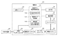
図1は、実施の形態にかかる電源制御装置を搭載した電動車20の構成を示すブロック図である。
電動車20は、電気自動車またはプラグインハイブリッド自動車など駆動エネルギーの少なくとも一部に電力を用いる外部充電可能な車両である。図1には電動車20の駆動機構の図示は省略しているが、電動車20は、駆動用バッテリ26に蓄電された電力により作動する駆動用モータを備えている。
電動車20は、電源制御装置として機能する車両ECU10の他、始動スイッチ22、充電インターフェース24、駆動用バッテリ26、DC/DCコンバータ28、補機バッテリ30、リレーボックス32、電装機器34、表示部36を備える。
A preferred embodiment of the power supply control device according to the present invention will be described in detail below with reference to the accompanying drawings.
FIG. 1 is a block diagram showing a configuration of an
The
The
始動スイッチ22(パワースイッチ)は、電動車20の電源モードを切り替えるためのスイッチであり、インストゥルメントパネルのステアリングホイールの近傍等に設けられている。本実施の形態では、電動車20の電源モードには、アクセサリ電源(ACC)のみがオンとなるACCオンモード、アクセサリ電源およびイグニッション電源(IG)がオンとなり全ての電装機器34が使用可能となるIGオンモード、およびアクセサリ電源およびイグニッション電源がオフとなるオフモードがある。以下、ACCオンモードおよびIGオンモード(いずれかの電源がオンとなっている状態)を合わせて「電源モードがオンモードである」という。
一般に、ACCオンモードでは、カーナビゲーションシステムやカーステレオなどの補機類に電源が供給され使用可能となる。また、IGオンモードでは、エアコンや電動ワイパーなど消費電力が大きい機器を含む全ての電装機器が使用可能となる。
電動車20の電源モードがオフモードにある時にブレーキペダルを踏まずに始動スイッチ22を1回押下すると電源モードはACCオンモードとなり、2回押下するとIGオンモード(ハイブリッド自動車においてはエンジンは始動しない)となり、3回押下するとオフモードに戻る。また、ブレーキペダルを踏んで始動スイッチ22を1回押下すると電源モードはIGオンモード(ハイブリッド自動車においてはエンジンも始動)となり、2回押下するとオフモードに戻る。
なお、始動スイッチ22への操作を有効にするためには、キーレスオペレーションキーを電動車20内に持ち込む必要がある。
The start switch 22 (power switch) is a switch for switching the power mode of the
Generally, in the ACC on mode, power is supplied to auxiliary equipment such as a car navigation system and a car stereo so that they can be used. Further, in the IG on mode, all electrical equipment including equipment having high power consumption such as an air conditioner and an electric wiper can be used.
When the power mode of the
In order to enable the operation of the
充電インターフェース24は、外部充電器40が接続されるインターフェースであり、車体外部に設けられたコネクタ等である。コネクタには外部充電器40から供給される電流が流れる電力線や外部充電器40側の制御部との間で通信を行うための通信線が設けられている。
外部充電器40が急速充電器である場合には充電インターフェース24は直接駆動用バッテリ26に接続され、外部充電器40が普通充電器である場合には充電インターフェース24は図示しない車内充電器を介して駆動用バッテリ26に接続される。
The
When the
駆動用バッテリ26は、300V程度の高電圧バッテリであり、電動車20の駆動用電力を蓄電する。駆動用バッテリ26の充電は、充電インターフェース24を介して接続された外部充電器40からの電力供給によって行われる。なお、駆動用バッテリ26に蓄積された電力は、駆動用モータの他電動エアコンの作動にも用いられる。
DC/DCコンバータ28は、駆動用バッテリ26に蓄電された電力を降圧して補機バッテリ30に供給する。
補機バッテリ30は、12V程度の低電圧バッテリであり、電動車20内の電装機器の作動用電力を蓄電する。補機バッテリ30の充電は、駆動用バッテリ26の電力をDC/DCコンバータ28で降圧して供給することによって行われる。
The
The DC /
The
リレーボックス32は、補機バッテリ30と各種電装機器34とを接続するリレーを収容する。リレーボックス32内のリレーを断接することによって、電装機器34への電力供給の可否を切り替えることができる。すなわち、電源モードの切り替えは、リレーボックス32内のリレーの断接によってなされる。
The relay box 32 accommodates a relay that connects the
電装機器34は、電動車20内に設けられ、補機バッテリ30または駆動用バッテリ26からの電力供給を受けて作動する機器類である。電装機器34の多くが補機バッテリ30からの電力供給を受けて作動し、電動エアコン等一部の電装機器34が駆動用バッテリ26からの電力供給を受けて作動する。なお、図示の便宜上、駆動用バッテリ26から電装機器34への電力線の図示は省略している。
電装機器34は、具体的には例えばヘッドランプやカーナビゲーションシステムやカーステレオ、電動ワイパー、電動エアコンなどである。また、電動車20の車内(または車外)に電源供給用のプラグ受けが設けられている場合には、プラグ受けに差込プラグを挿入することにより、車外から持ち込んだ電装機器34を使用可能である。
The
Specifically, the
表示部36は、例えばインストゥルメントパネルに設けられた小型ディスプレイ(コンビメータ)であり、後述する車両ECU10からの制御により車両状態など各種情報を表示する。
The
車両ECU10は、CPU、制御プログラムなどを格納・記憶するROM、制御プログラムの作動領域としてのRAM、各種データを書き換え可能に保持するEEPROM、周辺回路等とのインターフェースをとるインターフェース部などによって構成され、本実施の形態にかかる電源制御装置として機能する。
なお、本実施の形態では、後述する各種処理を車両ECU10のみで行っているものとして説明するが、複数の処理部が協同して後述する各種処理を行うようにしてもよい。例えば、車両ECU10の他にワンタッチスタートシステム(OSS)の制御を行うOSSコントローラや駆動用バッテリ26の状態を監視するBMU(Battery Management Unit)などを用いて、これらの処理部が協同して後述する各種処理を行うようにしてもよい。
The vehicle ECU 10 is composed of a CPU, a ROM for storing and storing a control program, a RAM as an operating area for the control program, an EEPROM for holding various data in a rewritable manner, an interface unit for interfacing with peripheral circuits, and the like. It functions as a power supply control device according to the present embodiment.
In this embodiment, it is assumed that the various processes described later are performed only by the vehicle ECU 10, but a plurality of processing units may cooperate to perform the various processes described later. For example, in addition to the vehicle ECU 10, an OSS controller that controls the one-touch start system (OSS), a BMU (Battery Management Unit) that monitors the state of the
車両ECU10は、上記CPUが上記制御プログラムを実行することにより、充電状態検知部102、電源モード切替部104、報知部106として機能する。
充電状態検知部102は、電動車20に搭載された駆動用バッテリ26への充電状態、特に充電が停止したか否かを検知する。充電状態検知部102は、充電インターフェース24を監視し、充電インターフェース24への外部充電器40の接続の有無や外部充電器40からの電力供給の有無、すなわち駆動用バッテリ26が充電中か否かを検知する。
駆動用バッテリ26が充電中か否かは、例えば充電インターフェース24に設けられた電力線における通電の有無や通信線を介して外部充電器40と通信される充電状態情報などに基づいて判断する。
充電が停止する場合とは、例えば駆動用バッテリ26が満充電になった場合や、外部充電器40の位置する地域が停電した場合、外部充電器40が故障した場合、タイマーにより設定した充電終了時刻となった場合、予め設定した充電電力量の供給が終了した場合などが挙げられる。
The vehicle ECU 10 functions as a charge
The charging
Whether or not the
When charging stops, for example, when the
報知部106は、請求項における第1の制御部および第2の制御部に対応し、後述する電源モード切替部104による電源モードの自動切り替えに関連した報知を行う。本実施の形態では、報知部106は、表示部36に報知内容を示すメッセージを表示することによって報知を行う。なお、報知部106による報知形態は、メッセージ表示に限らず、音声出力や警告灯の点灯など、従来公知の様々な形態を採用することができる。
The notification unit 106 corresponds to the first control unit and the second control unit in the claim, and performs notification related to automatic switching of the power supply mode by the power supply
電源モード切替部104は、電動車20の電源モードを切り替える。上述のように、電動車20の電源モードは、ユーザが始動スイッチ22を操作することにより切り替え可能であるが、以下のような状態下では、電源モード切替部104により自動的に電源モードが切り替えられる。
すなわち、電源モード切替部104は、電源モードがオンモードである際に駆動用バッテリ26への充電が停止した場合、電源モードをオフモードに切り替える。
ここで、電動車20では、外部充電器40からの充電中に電源モードをオンモードに切り替えて車内の電装機器34を使用可能である。外部充電器40からの充電中には、DC/DCコンバータ28が稼働して補機バッテリ30も充電される。よって、駆動用バッテリ26の充電中には電装機器34を使用しても外部充電器40からの電力供給があるので電動車20全体のバッテリ残量は維持される。
一方、駆動用バッテリ26の充電が停止した後は外部充電器40からの電力供給がなくなるので、電装機器34の使用を継続すると電動車20内のバッテリ残量が減少してしまう。このため、電源モード切替部104は、電源モードがオンモードである際に駆動用バッテリ26への充電が停止した場合には、電源モードをオフモードに切り替えて電装機器34の使用ができないようにする。
また、電源モード切替部104により自動的に電源モードがオフモードに切り替えられた後、ユーザが始動スイッチ22を操作することにより、再度オンモードにして電装機器34を使用することも可能である。また、後述するように、充電停止後、電源モードがオフモードに切り替えられるまでに猶予時間がある場合には、猶予時間中にユーザが所定の操作を行うことによりオンモードを継続させることを可能としてもよい。
The power
That is, when the power
Here, in the
On the other hand, since the power supply from the
Further, after the power supply mode is automatically switched to the off mode by the power supply
また、電源モード切替部104は、充電が停止した後、即座に電源モードを切り替えるのではなく、所定時間経過後に電源モードをオフモードに切り替えるようにしてもよい。
これは、例えば電装機器34がカーステレオ装置である場合にCD等から楽曲データを取り込んでいる場合や電装機器34がカーナビゲーション装置の場合に地図データのアップロード処理などを行っている場合に、即座に電源モードをオフモードに切り替えるとデータ等に不具合が生じる可能性があるためである。
Further, the power
This can be done immediately, for example, when music data is imported from a CD or the like when the
なお、このように電源をオフモードに切り替えるまでの猶予時間を持たせる場合、報知部106は、充電が停止した後所定時間(猶予時間)経過後に、電源モードがオフモードに切り替えられる旨をユーザに報知することが好ましい。
図3Bは、報知部106による報知の一例を示す説明図である。表示部36に、始動スイッチ22を示すイラストI2および所定時間後に電源がオフになる旨と使用中の電装機器に注意するよう促す旨のメッセージ表示M2が表示されている。
このように報知を行うことにより、ユーザが電源オフへの対応(電装機器34を用いた作業の切り上げや電源をオフしないことを選択する操作など)を行うことができ、利便性を向上させることができる。
When giving a grace period until the power is switched to the off mode in this way, the notification unit 106 informs the user that the power mode is switched to the off mode after a predetermined time (grace time) has elapsed after the charging is stopped. It is preferable to notify the user.
FIG. 3B is an explanatory diagram showing an example of notification by the notification unit 106. On the
By performing the notification in this way, the user can respond to the power off (such as rounding up the work using the
上述した所定時間(電源をオフモードに切り替えるまでの猶予時間の長さ)は、固定値であってもよいが、稼働中の電装機器34の消費電力に基づいて変更するようにしてもよい。すなわち、電源モード切替部104は、稼働中の電装機器34の消費電力に基づいて所定時間を変更するようにしてもよい。
具体的には、例えば充電が停止した後に消費可能な電力量の上限値(以下、「許容電力量」という)を設定しておき、稼働中の電装機器34の単位時間当たりの消費電力の合算値で上記許容電力量を除した値を所定時間として算出する。すなわち、許容電力量が少ないほど、又は稼働中の電装機器34の単位時間当たりの消費電力の合算値が大きいほど「所定時間」が短くなる。なお、許容電力量はユーザにより設定可能とするのが好ましい。これにより、駆動用バッテリ26の残量の減少量を許容範囲内に抑えることができ、バッテリ上がりを抑制することが容易となる。
なお、稼働中の電装機器34が増減したり、稼働状態が変化(例えば稼働中の電装機器34がエアコンであり設定温度や設定風量が変更された場合など)した場合などは、その都度所定時間を再算出してもよい。
The above-mentioned predetermined time (the length of the grace time until the power supply is switched to the off mode) may be a fixed value, but may be changed based on the power consumption of the operating
Specifically, for example, an upper limit value of the amount of power that can be consumed after charging is stopped (hereinafter referred to as "allowable power amount") is set, and the total power consumption per unit time of the operating
When the number of operating
また、電源モード切替部104は、稼働中の電装機器34の種類に基づいて所定時間を変更するようにしてもよい。
具体的には、例えばユーザが稼働を優先させたい電装機器34(以下、「優先電装機器」という)と、優先電装機器が稼働中である場合の猶予時間である第1の所定時間と、優先電装機器が稼働していない場合の猶予時間である第2の所定時間(<第1の所定時間)を予め設定しておく。充電停止時に優先電装機器が稼働中である場合には所定時間は第1の所定時間に、充電停止時に優先電装機器が稼働中でない場合には所定時間は第2の所定時間に、それぞれ設定される。
これにより、優先電装機器が稼働している場合には、優先電装機器が稼働していない場合よりも所定時間が長くなり、それに伴って長い時間に亘ってオンモードが継続され、優先電装機器の使用を相対的に長時間継続することができる。
また、例えば優先電装機器が稼働中である場合の第1の許容電力量と、優先電装機器が稼働していない場合の第2の許容電力量(<第1の許容電力量)を設定し、優先電装機器が稼働している場合には、優先電装機器が稼働していない場合よりも多くの電力消費を許容することにより、優先電装機器の使用を相対的に長時間継続できるようにしてもよい。
また、優先電装機器に代えて、ユーザが長時間稼働をさせたくない電装機器34(以下、「忌避電装機器」という)を指定し、忌避電装機器が稼働している場合には、忌避電装機器が稼働していない場合よりも短時間で電源をオフモードに切り替わるようにできるようにしてもよい。
Further, the power
Specifically, for example, an electrical device 34 (hereinafter referred to as "priority electrical device") for which the user wants to prioritize operation, a first predetermined time which is a grace time when the priority electrical device is in operation, and priority. A second predetermined time (<first predetermined time), which is a grace time when the electrical equipment is not operating, is set in advance. If the priority electrical equipment is operating when charging is stopped, the predetermined time is set to the first predetermined time, and if the priority electrical equipment is not operating when charging is stopped, the predetermined time is set to the second predetermined time. To.
As a result, when the priority electrical equipment is operating, the predetermined time is longer than when the priority electrical equipment is not operating, and the on-mode is continued for a long time accordingly, and the priority electrical equipment is operated. It can be used for a relatively long time.
Further, for example, a first allowable power amount when the priority electrical equipment is operating and a second allowable power amount when the priority electrical equipment is not operating (<first allowable power amount) are set. Even if the priority electrical equipment can be used for a relatively long time by allowing more power consumption when the priority electrical equipment is operating than when the priority electrical equipment is not operating. Good.
In addition, instead of the priority electrical equipment, the electrical equipment 34 (hereinafter referred to as "repellent equipment") that the user does not want to operate for a long time is designated, and when the repellent equipment is operating, the repellent equipment is operated. It may be possible to switch the power supply to the off mode in a shorter time than when is not in operation.
また、電源モード切替部104は、電動車20内の所定の電装機器34が稼働中の場合には、充電の停止後も電源モードをオンモードに維持するようにしてもよい。
所定の電装機器34とは、例えばヘッドランプや車幅灯、ハザードランプなど、自車両の存在を周囲に示すための電装機器などが挙げられる。例えば、停電により充電が停止した場合などは、周囲の街灯や照明などが使用できない状態になっている可能性があり、ヘッドランプ等を点灯させて自車両の存在を周囲に示すことが好ましい場合がある。このような場合は、充電の停止後も電源モードをオンモードに維持することにより安全性を向上させることができる。
Further, the power
Examples of the predetermined
なお、このように電源モードをオンモードに維持する場合、報知部106は、電装機器34に電力を供給するバッテリの残量低下への注意を促す報知を行うことが好ましい。
図3Aは、報知部106による報知の一例を示す説明図である。表示部36に、始動スイッチ22を示すイラストI1および所定の電装機器(図の例ではヘッドランプ)が稼働中のため電源のオンモードを継続する旨と使用中のバッテリ(補機バッテリ30)のバッテリ上がりに注意するよう促す旨のメッセージ表示M1が表示されている。
このように報知を行うことにより、ユーザは例えば稼働が必須ではない電装機器を停止させるなどの対応を行うことができ、利便性を向上させることができる。
When the power supply mode is maintained in the on mode in this way, it is preferable that the notification unit 106 gives a notification to call attention to a decrease in the remaining amount of the battery that supplies power to the
FIG. 3A is an explanatory diagram showing an example of notification by the notification unit 106. On the
By performing the notification in this way, the user can take measures such as stopping the electrical equipment that is not essential to operate, and the convenience can be improved.
図2は、車両ECU10(電源制御装置)の処理を示すフローチャートである。
まず、充電状態検知部102により駆動用バッテリ26への充電状態を検知する(ステップS200)。駆動用バッテリ26への充電が停止すると(ステップS200:Yes)、電源モード切替部104は、電動車20の電源モードがオンモード(電源オンモード)であるか否かを判断する(ステップS202)。
電源オンモードでない場合(ステップS202:No)、すなわち電源オフモードである場合には、駆動用バッテリ26および補機バッテリ30への影響はないので、そのまま本フローチャートの処理を終了する。
一方、電源オンモードの場合(ステップS202:Yes)、電源モード切替部104は、電動車20の所定の電装機器34(例えばヘッドランプや車幅灯など)が稼働しているか否かを判断する(ステップS204)。
例えば、安全性を確保するためヘッドランプや車幅灯などの所定の電装機器34が稼働している場合(ステップS204:Yes)、電源モード切替部104は、充電の停止後も電源モードをオンモードに維持する(ステップS206)。そして、報知部106により、電装機器34に電力を供給する補機バッテリの残量低下への注意を促す報知を行って(ステップS208)、本フローチャートの処理を終了する。
FIG. 2 is a flowchart showing the processing of the vehicle ECU 10 (power supply control device).
First, the charge
When the power-on mode is not set (step S202: No), that is, when the power-off mode is set, the
On the other hand, in the case of the power-on mode (step S202: Yes), the power
For example, when a predetermined
また、ステップS204で所定の電装機器34が稼働していない場合(ステップS204:No)、電源モード切替部104は、稼働中の電装機器34の消費電力または種類に基づいて電源モードをオフモードに切り替えるまでの猶予時間の長さ(所定時間)を決定する(ステップS209)。なお、上述のように所定時間は固定値であってもよい。
所定時間が決定されると、報知部106は、所定時間経過後に電源モードがオフモードに切り替わる(電源オフする)旨を報知する(ステップS210)。
その後、電源モード切替部104は、充電が停止してから所定時間が経過するまで待機して(ステップS212:Noのループ)、所定時間が経過すると(ステップS212:Yes)、電源モードをオフモードに切り替えて(ステップS214)、本フローチャートの処理を終了する。
If the predetermined
When the predetermined time is determined, the notification unit 106 notifies that the power mode is switched to the off mode (power is turned off) after the lapse of the predetermined time (step S210).
After that, the power
以上説明したように、実施の形態にかかる電源制御装置は、電動車20の電源モードがオンモードである際に駆動用バッテリ26への充電が停止した場合、自動的に電源モードをオフモードに切り替えるので、車内にユーザがいるかいないかに関わらずバッテリの残量低下を防止する上で有利となる。
また、電源制御装置は、所定の電装機器34が稼働中の場合には、充電の停止後も電源モードをオンモードに維持するので、電動車20の利便性を向上させる上で有利となる。例えば安全上の理由などで所定の電装機器34を稼働させている場合などには、充電停止後も引き続きユーザの安全を確保することができる。
また、電源制御装置は、電源モードをオンモードに維持する場合に、電装機器34に電力を供給する補機バッテリの残量低下への注意を促す報知を行うので、ユーザが予期しないバッテリ残量の低下(バッテリ上がりなど)を防止する上で有利となる。
また、電源制御装置は、充電が停止した後、所定時間経過後に電源モードをオフモードに切り替えるので、例えば電装機器34でデータ保存が必要な処理を行っている場合など、即座に電源がオフすると不都合が生じる場合などに有利となる。
また、電源制御装置は、充電が停止した後、所定時間経過後に電源モードがオフモードに切り替えられる旨を報知するので、ユーザが電源オフに対する対応を実施しやすくする上で有利となる。
また、電源制御装置において、稼働中の電装機器34の消費電力に基づいて所定時間を変更すれば、充電停止後のバッテリ残量の減少量を一定の範囲内に抑えることができる。
また、電源制御装置において、稼働中の電装機器の種類に基づいて所定時間を変更すれば、充電停止後の電装機器34の使用可能時間をユーザの嗜好等に合わせる上で有利となる。
As described above, the power supply control device according to the embodiment automatically changes the power supply mode to the off mode when the charging of the
Further, when the predetermined
Further, when the power supply mode is maintained in the on mode, the power supply control device gives a notification to call attention to a decrease in the remaining amount of the auxiliary battery that supplies power to the
Further, since the power control device switches the power mode to the off mode after a lapse of a predetermined time after charging is stopped, when the power is turned off immediately, for example, when the
Further, since the power control device notifies that the power mode is switched to the off mode after a lapse of a predetermined time after the charging is stopped, it is advantageous in facilitating the user to take measures against the power off.
Further, in the power supply control device, if the predetermined time is changed based on the power consumption of the operating
Further, in the power supply control device, if the predetermined time is changed based on the type of the electrical equipment in operation, it is advantageous in adjusting the usable time of the
10 車両ECU(電源制御装置)
102 充電状態検知部
104 電源モード切替部
106 報知部
20 電動車
22 始動スイッチ
24 充電インターフェース
26 駆動用バッテリ
28 DC/DCコンバータ
30 補機バッテリ
32 リレーボックス
34 電装機器
36 表示部
40 外部充電器
10 Vehicle ECU (power supply control device)
102
Claims (7)
前記電動車の電源モードを、前記電動車のアクセサリ電源またはイグニッション電源をオンとし補機バッテリから電装機器への電力供給が可能となるオンモードと、前記アクセサリ電源および前記イグニッション電源の両方がオフとなり前記補機バッテリから電装機器への電力供給が不可となるオフモードとを切り替える電源モード切替部と、を備え、
前記電源モード切替部は、前記電源モードがオンモードである際に前記駆動用バッテリへの充電が停止した場合、前記電源モードをオフモードに切り替えるとともに、前記電動車の所定の電装機器が稼働中の場合には、前記充電の停止後も前記電源モードを前記オンモードに維持する、
ことを特徴とする電源制御装置。 A charge status detector that detects the charge status of the drive battery mounted on the electric vehicle from an external charger ,
The power mode of the electric vehicle is set to an on mode in which the accessory power supply or the ignition power supply of the electric vehicle is turned on so that power can be supplied from the auxiliary battery to the electrical equipment, and both the accessory power supply and the ignition power supply are turned off. It is equipped with a power mode switching unit that switches between an off mode in which power cannot be supplied from the auxiliary battery to the electrical equipment .
When the charging of the drive battery is stopped while the power supply mode is the on mode, the power supply mode switching unit switches the power supply mode to the off mode and a predetermined electrical device of the electric vehicle is in operation. In the case of, the power mode is maintained in the on mode even after the charging is stopped .
A power control device characterized by that.
ことを特徴とする請求項1記載の電源制御装置。 When the power supply mode is maintained in the on mode, a first notification unit for notifying attention to a decrease in the remaining amount of the auxiliary battery that supplies power to the electrical equipment is further provided.
The power supply control device according to claim 1 .
ことを特徴とする請求項1記載の電源制御装置。 The power supply mode switching unit switches the power supply mode to the off mode after a lapse of a predetermined time after the charging is stopped.
The power supply control device according to claim 1 .
ことを特徴とする請求項3記載の電源制御装置。 A second notification unit for notifying that the power supply mode is switched to the off mode after the elapse of the predetermined time after the charging is stopped is further provided.
The power supply control device according to claim 3 .
ことを特徴とする請求項3または4記載の電源制御装置。 The power mode switching unit changes the predetermined time based on the power consumption of the operating electrical equipment.
The power supply control device according to claim 3 or 4 .
ことを特徴とする請求項3または4記載の電源制御装置。 The power mode switching unit changes the predetermined time based on the type of electrical equipment in operation.
The power supply control device according to claim 3 or 4 .
前記電動車の電源モードを、前記電動車のアクセサリ電源またはイグニッション電源をオンとし補機バッテリから電装機器への電力供給が可能となるオンモードと、前記アクセサリ電源および前記イグニッション電源の両方がオフとなり前記補機バッテリから電装機器への電力供給が不可となるオフモードとを切り替える電源モード切替部と、を備え、The power mode of the electric vehicle is set to an on mode in which the accessory power supply or the ignition power supply of the electric vehicle is turned on so that power can be supplied from the auxiliary battery to the electrical equipment, and both the accessory power supply and the ignition power supply are turned off. It is provided with a power mode switching unit that switches between an off mode in which power cannot be supplied from the auxiliary battery to the electrical equipment.
前記電源モード切替部は、前記アクセサリ電源をオンとしたオンモード、及び前記イグニッション電源をオンとしたオンモードのいずれかの際に前記駆動用バッテリへの充電が停止した場合、前記電源モードをオフモードに切り替える、The power mode switching unit turns off the power mode when charging of the drive battery is stopped in either the on mode in which the accessory power is turned on or the on mode in which the ignition power is turned on. Switch to mode,
ことを特徴とする電源制御装置。A power control device characterized by that.
Priority Applications (4)
| Application Number | Priority Date | Filing Date | Title |
|---|---|---|---|
| JP2016238979A JP6812771B2 (en) | 2016-12-09 | 2016-12-09 | Power control unit |
| EP17205755.6A EP3333004B1 (en) | 2016-12-09 | 2017-12-06 | Power source control device and power source control method |
| US15/833,651 US10245969B2 (en) | 2016-12-09 | 2017-12-06 | Power source control device and power source control method |
| CN201711293822.3A CN108215875B (en) | 2016-12-09 | 2017-12-08 | Power supply control device and power supply control method |
Applications Claiming Priority (1)
| Application Number | Priority Date | Filing Date | Title |
|---|---|---|---|
| JP2016238979A JP6812771B2 (en) | 2016-12-09 | 2016-12-09 | Power control unit |
Publications (2)
| Publication Number | Publication Date |
|---|---|
| JP2018098844A JP2018098844A (en) | 2018-06-21 |
| JP6812771B2 true JP6812771B2 (en) | 2021-01-13 |
Family
ID=60627498
Family Applications (1)
| Application Number | Title | Priority Date | Filing Date |
|---|---|---|---|
| JP2016238979A Active JP6812771B2 (en) | 2016-12-09 | 2016-12-09 | Power control unit |
Country Status (4)
| Country | Link |
|---|---|
| US (1) | US10245969B2 (en) |
| EP (1) | EP3333004B1 (en) |
| JP (1) | JP6812771B2 (en) |
| CN (1) | CN108215875B (en) |
Families Citing this family (3)
| Publication number | Priority date | Publication date | Assignee | Title |
|---|---|---|---|---|
| JP7272295B2 (en) * | 2020-01-31 | 2023-05-12 | トヨタ自動車株式会社 | vehicle |
| MX2022013368A (en) | 2020-04-27 | 2022-11-30 | Nissan Motor | Power supply control method and power supply control device. |
| JP2024021167A (en) * | 2022-08-03 | 2024-02-16 | 株式会社クボタ | electric work vehicle |
Family Cites Families (13)
| Publication number | Priority date | Publication date | Assignee | Title |
|---|---|---|---|---|
| JPS4990B1 (en) | 1969-05-17 | 1974-01-05 | ||
| JP2005354827A (en) * | 2004-06-11 | 2005-12-22 | Auto Network Gijutsu Kenkyusho:Kk | Battery degradation preventer |
| JP4479400B2 (en) | 2004-07-27 | 2010-06-09 | 株式会社デンソー | Smart entry system |
| JP4900090B2 (en) | 2007-07-03 | 2012-03-21 | トヨタ自動車株式会社 | Vehicle start control device |
| JP5181765B2 (en) | 2008-03-25 | 2013-04-10 | マツダ株式会社 | Battery monitoring device and battery control device using the monitoring device |
| ES2548570T3 (en) * | 2009-03-24 | 2015-10-19 | Gambro Lundia Ab | Dialysis device |
| JP5503983B2 (en) | 2010-01-27 | 2014-05-28 | 本田技研工業株式会社 | Electric vehicle |
| JP5293841B2 (en) * | 2010-02-09 | 2013-09-18 | トヨタ自動車株式会社 | Electric vehicle power supply system and control method thereof |
| JP5479999B2 (en) * | 2010-04-28 | 2014-04-23 | トヨタ自動車株式会社 | Vehicle power supply |
| JP5659771B2 (en) * | 2010-12-17 | 2015-01-28 | トヨタ自動車株式会社 | Vehicle and vehicle control method |
| JP5715107B2 (en) * | 2012-10-29 | 2015-05-07 | 富士通テン株式会社 | Control system |
| JP6103041B2 (en) * | 2013-04-05 | 2017-03-29 | 日産自動車株式会社 | Vehicle power supply |
| WO2014162882A1 (en) | 2013-04-05 | 2014-10-09 | 日産自動車株式会社 | Vehicular power supply device |
-
2016
- 2016-12-09 JP JP2016238979A patent/JP6812771B2/en active Active
-
2017
- 2017-12-06 US US15/833,651 patent/US10245969B2/en active Active
- 2017-12-06 EP EP17205755.6A patent/EP3333004B1/en active Active
- 2017-12-08 CN CN201711293822.3A patent/CN108215875B/en active Active
Also Published As
| Publication number | Publication date |
|---|---|
| EP3333004A1 (en) | 2018-06-13 |
| US10245969B2 (en) | 2019-04-02 |
| JP2018098844A (en) | 2018-06-21 |
| CN108215875A (en) | 2018-06-29 |
| CN108215875B (en) | 2021-05-07 |
| US20180162230A1 (en) | 2018-06-14 |
| EP3333004B1 (en) | 2019-07-31 |
Similar Documents
| Publication | Publication Date | Title |
|---|---|---|
| US7629706B2 (en) | Feed limiting device for limiting feed to electrical components and control device | |
| JP3549806B2 (en) | Automotive power supply controller | |
| EP3012145B1 (en) | Power supply device for auxiliary device battery | |
| JP5247520B2 (en) | Power control apparatus and method, and program | |
| KR101459946B1 (en) | Power control system and method for vehicle power outlet | |
| CN108032735B (en) | Control method and device for vehicle high-voltage accessory and electric vehicle with control device | |
| JP6812771B2 (en) | Power control unit | |
| RU2589223C1 (en) | Vehicle power supply device | |
| JPWO2011099116A1 (en) | Electric vehicle power supply system and control method thereof | |
| JP2007228753A (en) | Electric vehicle | |
| JP5846210B2 (en) | Vehicle and vehicle control method | |
| JP2013207949A (en) | Charging control device for electric vehicle | |
| JP2010213556A (en) | Charging apparatus, and information presentation method | |
| CN112078423B (en) | Vehicle high-voltage power-on control method, vehicle control unit, system and vehicle | |
| KR101765934B1 (en) | Vehicle Starting Apparatus and Control Method thereof | |
| WO2014162882A1 (en) | Vehicular power supply device | |
| CN111361419B (en) | Power-on and power-off control method and system for explosion-proof automobile | |
| KR101546046B1 (en) | System for preventing battery discharge of electric power cart and method thereof | |
| CN116141974A (en) | Vehicle power supply device, power supply method and vehicle | |
| JP2019170129A (en) | Battery charging controller for electric vehicle | |
| JP6171966B2 (en) | In-vehicle power supply system | |
| KR101257024B1 (en) | Regular power supplying apparatus having user switch | |
| KR20130005783A (en) | Apparatus managing power of auxiliary electronic equipment using battery sensor | |
| JP2008074167A (en) | Power supply control device for automobile | |
| US10279689B2 (en) | Battery rescue activating reset device |
Legal Events
| Date | Code | Title | Description |
|---|---|---|---|
| A621 | Written request for application examination |
Free format text: JAPANESE INTERMEDIATE CODE: A621 Effective date: 20190322 |
|
| A977 | Report on retrieval |
Free format text: JAPANESE INTERMEDIATE CODE: A971007 Effective date: 20200228 |
|
| A131 | Notification of reasons for refusal |
Free format text: JAPANESE INTERMEDIATE CODE: A131 Effective date: 20200407 |
|
| A521 | Request for written amendment filed |
Free format text: JAPANESE INTERMEDIATE CODE: A523 Effective date: 20200608 |
|
| TRDD | Decision of grant or rejection written | ||
| A01 | Written decision to grant a patent or to grant a registration (utility model) |
Free format text: JAPANESE INTERMEDIATE CODE: A01 Effective date: 20201117 |
|
| A61 | First payment of annual fees (during grant procedure) |
Free format text: JAPANESE INTERMEDIATE CODE: A61 Effective date: 20201130 |
|
| R151 | Written notification of patent or utility model registration |
Ref document number: 6812771 Country of ref document: JP Free format text: JAPANESE INTERMEDIATE CODE: R151 |