JP6810168B2 - Inlet guide vanes and compressors - Google Patents
Inlet guide vanes and compressors Download PDFInfo
- Publication number
- JP6810168B2 JP6810168B2 JP2018565218A JP2018565218A JP6810168B2 JP 6810168 B2 JP6810168 B2 JP 6810168B2 JP 2018565218 A JP2018565218 A JP 2018565218A JP 2018565218 A JP2018565218 A JP 2018565218A JP 6810168 B2 JP6810168 B2 JP 6810168B2
- Authority
- JP
- Japan
- Prior art keywords
- seal
- fluid
- shaft portion
- seal member
- inlet guide
- Prior art date
- Legal status (The legal status is an assumption and is not a legal conclusion. Google has not performed a legal analysis and makes no representation as to the accuracy of the status listed.)
- Active
Links
- 239000012530 fluid Substances 0.000 claims description 94
- 238000007789 sealing Methods 0.000 claims description 78
- 230000002093 peripheral effect Effects 0.000 claims description 66
- 238000003780 insertion Methods 0.000 claims description 45
- 230000037431 insertion Effects 0.000 claims description 45
- 238000007906 compression Methods 0.000 description 57
- 230000006835 compression Effects 0.000 description 55
- 239000000463 material Substances 0.000 description 4
- 238000004891 communication Methods 0.000 description 3
- 238000001816 cooling Methods 0.000 description 3
- 238000003825 pressing Methods 0.000 description 3
- 230000006866 deterioration Effects 0.000 description 2
- 230000001771 impaired effect Effects 0.000 description 2
- 230000000149 penetrating effect Effects 0.000 description 2
- 239000013013 elastic material Substances 0.000 description 1
- 230000002708 enhancing effect Effects 0.000 description 1
- 238000012423 maintenance Methods 0.000 description 1
- 239000000126 substance Substances 0.000 description 1
Images


Classifications
-
- F—MECHANICAL ENGINEERING; LIGHTING; HEATING; WEAPONS; BLASTING
- F01—MACHINES OR ENGINES IN GENERAL; ENGINE PLANTS IN GENERAL; STEAM ENGINES
- F01D—NON-POSITIVE DISPLACEMENT MACHINES OR ENGINES, e.g. STEAM TURBINES
- F01D17/00—Regulating or controlling by varying flow
- F01D17/10—Final actuators
- F01D17/12—Final actuators arranged in stator parts
- F01D17/14—Final actuators arranged in stator parts varying effective cross-sectional area of nozzles or guide conduits
- F01D17/16—Final actuators arranged in stator parts varying effective cross-sectional area of nozzles or guide conduits by means of nozzle vanes
- F01D17/162—Final actuators arranged in stator parts varying effective cross-sectional area of nozzles or guide conduits by means of nozzle vanes for axial flow, i.e. the vanes turning around axes which are essentially perpendicular to the rotor centre line
-
- F—MECHANICAL ENGINEERING; LIGHTING; HEATING; WEAPONS; BLASTING
- F04—POSITIVE - DISPLACEMENT MACHINES FOR LIQUIDS; PUMPS FOR LIQUIDS OR ELASTIC FLUIDS
- F04D—NON-POSITIVE-DISPLACEMENT PUMPS
- F04D25/00—Pumping installations or systems
- F04D25/16—Combinations of two or more pumps ; Producing two or more separate gas flows
- F04D25/163—Combinations of two or more pumps ; Producing two or more separate gas flows driven by a common gearing arrangement
-
- F—MECHANICAL ENGINEERING; LIGHTING; HEATING; WEAPONS; BLASTING
- F04—POSITIVE - DISPLACEMENT MACHINES FOR LIQUIDS; PUMPS FOR LIQUIDS OR ELASTIC FLUIDS
- F04D—NON-POSITIVE-DISPLACEMENT PUMPS
- F04D29/00—Details, component parts, or accessories
- F04D29/05—Shafts or bearings, or assemblies thereof, specially adapted for elastic fluid pumps
- F04D29/056—Bearings
- F04D29/057—Bearings hydrostatic; hydrodynamic
-
- F—MECHANICAL ENGINEERING; LIGHTING; HEATING; WEAPONS; BLASTING
- F04—POSITIVE - DISPLACEMENT MACHINES FOR LIQUIDS; PUMPS FOR LIQUIDS OR ELASTIC FLUIDS
- F04D—NON-POSITIVE-DISPLACEMENT PUMPS
- F04D29/00—Details, component parts, or accessories
- F04D29/08—Sealings
- F04D29/083—Sealings especially adapted for elastic fluid pumps
-
- F—MECHANICAL ENGINEERING; LIGHTING; HEATING; WEAPONS; BLASTING
- F04—POSITIVE - DISPLACEMENT MACHINES FOR LIQUIDS; PUMPS FOR LIQUIDS OR ELASTIC FLUIDS
- F04D—NON-POSITIVE-DISPLACEMENT PUMPS
- F04D29/00—Details, component parts, or accessories
- F04D29/40—Casings; Connections of working fluid
- F04D29/42—Casings; Connections of working fluid for radial or helico-centrifugal pumps
- F04D29/44—Fluid-guiding means, e.g. diffusers
- F04D29/46—Fluid-guiding means, e.g. diffusers adjustable
- F04D29/462—Fluid-guiding means, e.g. diffusers adjustable especially adapted for elastic fluid pumps
-
- F—MECHANICAL ENGINEERING; LIGHTING; HEATING; WEAPONS; BLASTING
- F04—POSITIVE - DISPLACEMENT MACHINES FOR LIQUIDS; PUMPS FOR LIQUIDS OR ELASTIC FLUIDS
- F04D—NON-POSITIVE-DISPLACEMENT PUMPS
- F04D29/00—Details, component parts, or accessories
- F04D29/40—Casings; Connections of working fluid
- F04D29/52—Casings; Connections of working fluid for axial pumps
- F04D29/54—Fluid-guiding means, e.g. diffusers
- F04D29/56—Fluid-guiding means, e.g. diffusers adjustable
- F04D29/563—Fluid-guiding means, e.g. diffusers adjustable specially adapted for elastic fluid pumps
-
- F—MECHANICAL ENGINEERING; LIGHTING; HEATING; WEAPONS; BLASTING
- F05—INDEXING SCHEMES RELATING TO ENGINES OR PUMPS IN VARIOUS SUBCLASSES OF CLASSES F01-F04
- F05D—INDEXING SCHEME FOR ASPECTS RELATING TO NON-POSITIVE-DISPLACEMENT MACHINES OR ENGINES, GAS-TURBINES OR JET-PROPULSION PLANTS
- F05D2220/00—Application
- F05D2220/30—Application in turbines
- F05D2220/32—Application in turbines in gas turbines
-
- F—MECHANICAL ENGINEERING; LIGHTING; HEATING; WEAPONS; BLASTING
- F05—INDEXING SCHEMES RELATING TO ENGINES OR PUMPS IN VARIOUS SUBCLASSES OF CLASSES F01-F04
- F05D—INDEXING SCHEME FOR ASPECTS RELATING TO NON-POSITIVE-DISPLACEMENT MACHINES OR ENGINES, GAS-TURBINES OR JET-PROPULSION PLANTS
- F05D2250/00—Geometry
- F05D2250/50—Inlet or outlet
- F05D2250/51—Inlet
Description
この発明は、インレットガイドベーン及び圧縮機に関する。 The present invention relates to inlet guide vanes and compressors.
例えば、遠心圧縮機は、回転するインペラの内部に流体を流通させ、インペラが回転する際に発生する遠心力を利用してガス状態の流体を圧縮する。このような遠心圧縮機には運転範囲を広くするために入口案内翼(インレットガイドベーン)の角度を変え外部から導入する流体の流量を調整することができる可変式のインレットガイドベーン(Inlet Guide Vane:IGV)を備えたものがある。 For example, a centrifugal compressor circulates a fluid inside a rotating impeller and uses centrifugal force generated when the impeller rotates to compress a fluid in a gaseous state. In such a centrifugal compressor, a variable inlet guide vane (Inlet Guide Vane) that can adjust the flow rate of the fluid introduced from the outside by changing the angle of the inlet guide vane (inlet guide vane) in order to widen the operating range. : IGV) is provided.
インレットガイドベーンは、外部から遠心圧縮機のハウジング内に流体を導入する入口流路に設けられる。インレットガイドベーンは、入口流路に固定されるベーンケース(Vane case)と、ベーンケースに支持されて開度が調整可能な複数枚の可動翼を備えている。各可動翼は、翼本体と、翼本体と一体に形成される軸部と、を有している。可動翼は、軸部が、ベーンケースに形成された軸孔に、ブッシュ等の軸受を介して回動自在に支持されている。 The inlet guide vane is provided in the inlet flow path for introducing a fluid into the housing of the centrifugal compressor from the outside. The inlet guide vane is provided with a vane case fixed to the inlet flow path and a plurality of movable wings supported by the vane case and whose opening degree can be adjusted. Each movable wing has a wing body and a shaft portion integrally formed with the wing body. The shaft portion of the movable wing is rotatably supported by a shaft hole formed in the vane case via a bearing such as a bush.
ところで、可動翼の軸部が軸孔内で回動自在となるよう、軸受と軸部との間には微少なクリアランスが形成されている。この微少なクリアランスを通して、流体が外部に漏れ出てしまう。 By the way, a minute clearance is formed between the bearing and the shaft portion so that the shaft portion of the movable blade can rotate in the shaft hole. Through this minute clearance, the fluid leaks to the outside.
そこで、例えば特許文献1には、可動翼の軸部のクリアランスを通しての流体の漏出を抑えるため、シール部材を設ける構成が開示されている。 Therefore, for example, Patent Document 1 discloses a configuration in which a seal member is provided in order to suppress leakage of fluid through the clearance of the shaft portion of the movable blade.
しかしながら、流路内の流体が高圧で、流路外の雰囲気との差圧が大きい場合、その差圧によってシール部材におけるシール性が損なわれる場合が有る。そのため、可動翼の軸部におけるシール性を高めることが望まれている。 However, when the fluid in the flow path has a high pressure and the differential pressure from the atmosphere outside the flow path is large, the differential pressure may impair the sealing property of the sealing member. Therefore, it is desired to improve the sealing property at the shaft portion of the movable blade.
本発明は、可動翼の軸部におけるシール性を高めることが可能なインレットガイドベーン及び圧縮機を提供する。 The present invention provides an inlet guide vane and a compressor capable of enhancing the sealing property at the shaft portion of the movable blade.
本発明の第一の態様に係るインレットガイドベーンは、翼本体、及び前記翼本体の端部に設けられた軸部を有する可動翼と、前記軸部が挿入される挿入孔が形成されたフレームと、前記挿入孔の内部で前記軸部の中心軸方向に間隔をあけて複数設けられ、前記フレームに対して前記中心軸周りに回転可能に前記軸部を支持する軸受部と、前記挿入孔の内部で前記中心軸方向における複数の前記軸受部の間に配置され、前記挿入孔と前記軸部との間をシールするシール部と、を備え、前記シール部は、前記中心軸方向に間隔をあけて配置された第一シール部材と第二シール部材とを備え、前記第一シール部材と前記第二シール部材とは、互いに異なるシール構造を有し、前記シール部は、前記軸部の径方向外側で周方向に連続する環状をなし、前記フレームに対して前記翼本体が配置されている側に向かって開口する溝が形成された弾性リング部と、前記溝に設けられ、前記弾性リング部の内周面を前記軸部に向かって径方向内側に付勢する付勢部材と、を備える。 The inlet guide vane according to the first aspect of the present invention is a frame in which a blade body, a movable blade having a shaft portion provided at an end portion of the blade body, and an insertion hole into which the shaft portion is inserted are formed. A bearing portion that is provided inside the insertion hole at intervals in the central axis direction of the shaft portion and that rotatably supports the shaft portion around the central axis with respect to the frame, and the insertion hole. A seal portion that is arranged between a plurality of the bearing portions in the central axial direction and seals between the insertion hole and the shaft portion is provided inside the above, and the seal portions are spaced apart in the central axial direction. and a first sealing member and the second seal member that is spaced, said the first sealing member and the second sealing member, possess different seal structure from each other, the seal portion, of the shaft portion An elastic ring portion having an annular shape that is continuous in the circumferential direction on the outer side in the radial direction and has a groove that opens toward the side where the blade body is arranged with respect to the frame, and an elastic ring portion that is provided in the groove and has the elasticity. An urging member for urging the inner peripheral surface of the ring portion inward in the radial direction toward the shaft portion is provided.
このような構成によれば、複数の軸受部の間に配置されたシール部によって、挿入孔の内周面と軸部の外周面との間を通って流路内の流体が漏れることを抑える。シール部には
、軸受部と軸部の外周面との間の隙間を通り抜けた流体のみが到達する。そのため、シール部は、流体に曝されにくくなり、流体の影響を受けにくくなる。したがって、シール部の劣化を抑えて、高いシール性を継続して発揮させることができる。
また、第一シール部材と第二シール部材とによってシール部を二重の構成とすることで、シール性を高めることができる。
また、第一シール部材と第二シール部材とでシール構造を互いに異ならせることで、複数種のシール特性を有したシール部が構成される。その結果、高いシール性が確保される。
また、付勢部材によって弾性リング部の内周面を径方向内側に付勢することで、シール部と軸部との間のシール性を高めることができる。また、弾性リング部の溝が、流体の流路側である翼本体が配置されている側に開口しているので、流路側から流体が漏れてきたときに、この流体が溝内に入り込む。流体が溝内に入り込むことによって、弾性リング部の内周面が径方向内側に押圧され、シール部と軸部との間のシール性を高めることができる。
According to such a configuration, the seal portion arranged between the plurality of bearing portions prevents the fluid in the flow path from leaking through between the inner peripheral surface of the insertion hole and the outer peripheral surface of the shaft portion. .. Only the fluid that has passed through the gap between the bearing portion and the outer peripheral surface of the shaft portion reaches the seal portion. Therefore, the seal portion is less likely to be exposed to the fluid and is less likely to be affected by the fluid. Therefore, it is possible to suppress deterioration of the sealing portion and continuously exhibit high sealing performance.
Further, the sealing property can be improved by forming the sealing portion with the first sealing member and the second sealing member in a double structure.
Further, by making the seal structures of the first seal member and the second seal member different from each other, a seal portion having a plurality of types of seal characteristics is configured. As a result, high sealing performance is ensured.
Further, by urging the inner peripheral surface of the elastic ring portion inward in the radial direction by the urging member, the sealing property between the sealing portion and the shaft portion can be improved. Further, since the groove of the elastic ring portion is opened on the side where the blade body is arranged, which is the flow path side of the fluid, when the fluid leaks from the flow path side, this fluid enters the groove. When the fluid enters the groove, the inner peripheral surface of the elastic ring portion is pressed inward in the radial direction, and the sealing property between the sealing portion and the shaft portion can be improved.
本発明の第二の態様に係るインレットガイドベーンでは、第一の態様において、前記第一シール部材は、前記第二シール部材よりも前記翼本体に近い位置に配置され、前記第二シール部材よりも高いシール性を有していてもよい。 In the inlet guide vane according to the second aspect of the present invention, in the first aspect, the first seal member is arranged at a position closer to the wing body than the second seal member, and from the second seal member. May also have high sealing properties.
このような構成によれば、翼本体側からの流体の漏れを、シール性の高い第一シール部材によって有効に抑えることができる。さらに、第一シール部材を通り抜けた流体のみをシールするバックアップとして第二シール部材を機能させることで、第二シール部材のシール性を抑えても、シール部全体としてのシール性を確保できる。その結果、第二シール部材のコストを抑えることができる。 According to such a configuration, the leakage of the fluid from the blade body side can be effectively suppressed by the first sealing member having a high sealing property. Further, by making the second seal member function as a backup for sealing only the fluid that has passed through the first seal member, the sealability of the entire seal portion can be ensured even if the sealability of the second seal member is suppressed. As a result, the cost of the second seal member can be suppressed.
本発明の第三の態様に係るインレットガイドベーンでは、第一又は第二の態様において、前記第一シール部材と前記第二シール部材との間に、前記挿入孔の内周面に形成されて径方向外側に窪む孔側凹部、及び前記軸部の外周面に形成されて径方向内側に窪む軸側凹部の少なくとも一方が形成されていてもよい。 In the inlet guide vane according to the third aspect of the present invention, in the first or second aspect , the inlet guide vane is formed on the inner peripheral surface of the insertion hole between the first seal member and the second seal member. At least one of a hole-side recess that is recessed outward in the radial direction and a shaft-side recess that is formed on the outer peripheral surface of the shaft portion and is recessed inward in the radial direction may be formed.
このような構成によれば、第一シール部材と第二シール部材との間に、孔側凹部及び軸側凹部の少なくとも一方によって、挿入孔の内周面と軸部の外周面との間の隙間の断面積が拡大された空間が形成される。そのため、仮に流路側から流体が漏れた場合であっても、この空間に流体が貯留され、流体の漏出を抑えることができる。これによって、例えば第一シール部材側から流体が流入してきて、第一シール部材におけるシール性が損なわれても、シール部としてのシール性が損なわれることが抑えられる。 According to such a configuration, between the first seal member and the second seal member, at least one of the hole-side recess and the shaft-side recess is provided between the inner peripheral surface of the insertion hole and the outer peripheral surface of the shaft portion. A space is formed in which the cross-sectional area of the gap is expanded. Therefore, even if the fluid leaks from the flow path side, the fluid is stored in this space, and the leakage of the fluid can be suppressed. As a result, for example, even if a fluid flows in from the first seal member side and the seal property of the first seal member is impaired, the seal property of the seal portion is suppressed from being impaired.
本発明の第四の態様に係るインレットガイドベーンでは、第一から第三の態様のいずれか一つにおいて、前記第一シール部材と前記第二シール部材との間に設けられ、前記挿入孔の内周面と前記軸部の外周面との隙間に流体が侵入したことを検知するセンサをさらに備えていてもよい。 In the inlet guide vane according to the fourth aspect of the present invention, in any one of the first to third aspects, the inlet guide vane is provided between the first seal member and the second seal member, and is provided in the insertion hole. A sensor that detects that a fluid has entered the gap between the inner peripheral surface and the outer peripheral surface of the shaft portion may be further provided.
このような構成によれば、流路側から流体が漏れてきたことを、センサで検知することができる。 According to such a configuration, the sensor can detect that the fluid has leaked from the flow path side.
本発明の第五の態様に係るインレットガイドベーンでは、第一から第四の態様のいずれか一つにおいて、前記第一シール部材と前記第二シール部材との間において、前記挿入孔の内周面と前記軸部の外周面との隙間に、外部からシール用流体を供給するシール用流体供給部をさらに備えていてもよい。 In the inlet guide vane according to the fifth aspect of the present invention, in any one of the first to fourth aspects, the inner circumference of the insertion hole is between the first seal member and the second seal member. A sealing fluid supply unit that supplies a sealing fluid from the outside may be further provided in the gap between the surface and the outer peripheral surface of the shaft portion.
このような構成によれば、第一シール部材と第二シール部材との間に外部からシール用流体が送り込まれることで、流路内の流体が第一シール部材と第二シール部材との間に流れ込むことを抑える。 According to such a configuration, the sealing fluid is sent from the outside between the first sealing member and the second sealing member, so that the fluid in the flow path is between the first sealing member and the second sealing member. Suppress the flow into.
このような構成によれば、付勢部材によって弾性リング部の内周面を径方向内側に付勢することで、シール部と軸部との間のシール性を高めることができる。また、弾性リング部の溝が、流体の流路側である翼本体が配置されている側に開口しているので、流路側から流体が漏れてきたときに、この流体が溝内に入り込む。流体が溝内に入り込むことによって、弾性リング部の内周面が径方向内側に押圧され、シール部と軸部との間のシール性を高めることができる。 According to such a configuration, the inner peripheral surface of the elastic ring portion is urged inward in the radial direction by the urging member, so that the sealing property between the sealing portion and the shaft portion can be improved. Further, since the groove of the elastic ring portion is opened on the side where the blade body is arranged, which is the flow path side of the fluid, when the fluid leaks from the flow path side, this fluid enters the groove. When the fluid enters the groove, the inner peripheral surface of the elastic ring portion is pressed inward in the radial direction, and the sealing property between the sealing portion and the shaft portion can be improved.
本発明の第六の態様に係る圧縮機は、上記したようなインレットガイドベーンを備える。 The compressor according to the sixth aspect of the present invention includes an inlet guide vane as described above.
このような構成によれば、複数の軸受部の間に配置されたシール部によって、挿入孔の内周面と軸部の外周面との間を通って流路内の流体が漏れることを抑える。これによって、流体として、可燃性ガス等を取り扱う圧縮機においても、インレットガイドベーンを有効に適用することが可能となる。 According to such a configuration, the seal portion arranged between the plurality of bearing portions prevents the fluid in the flow path from leaking through between the inner peripheral surface of the insertion hole and the outer peripheral surface of the shaft portion. .. This makes it possible to effectively apply the inlet guide vane even in a compressor that handles flammable gas or the like as a fluid.
本発明によれば、可動翼の軸部におけるシール性を高めることが可能となる。 According to the present invention, it is possible to improve the sealing property at the shaft portion of the movable blade.
《第一実施形態》
以下、図面を参照して、本発明のインレットガイドベーン及び圧縮機を説明する。図1に示すように、遠心圧縮機システム1は、動力を発生させる駆動源19と、駆動軸2と、従動軸3と、圧縮部4と、増速機10と、を備える。<< First Embodiment >>
Hereinafter, the inlet guide vane and the compressor of the present invention will be described with reference to the drawings. As shown in FIG. 1, the centrifugal compressor system 1 includes a
駆動軸2は、駆動源19によって、その中心軸回りに回転駆動される。駆動源19としては、例えば、蒸気タービン、モータ等を用いることができる。
The
従動軸3は、増速機10から伝達された動力により、その中心軸回りに回転駆動される。従動軸3は、駆動軸2を挟んで両側に配置されている。従動軸3は、それぞれ駆動軸2と平行に延びている第一従動軸5及び第二従動軸6を有する。
The driven
増速機10は、駆動軸2の回転を増速し、第一従動軸5と第二従動軸6とに伝達させる。増速機10は、ケーシング20内に、駆動歯車11と、第一従動歯車12及び第二従動歯車13と、第一中間歯車14及び第二中間歯車15と、を備える。
The
駆動歯車11は、ケーシング20を貫通してケーシング20内に挿入された駆動軸2の先端部に設けられ、駆動軸2と一体に回転する。ここで、駆動軸2は、ケーシング20に軸受(図示無し)を介して支持されている。
The
第一従動歯車12は、第一従動軸5の中心軸方向の中間部に、第一従動軸5と一体に設けられている。第二従動歯車13は、第二従動軸6の中心軸方向の中間部に、第二従動軸6と一体に設けられている。第一従動軸5及び第二従動軸6は、ケーシング20に軸受(図示無し)を介して支持されている。これら第一従動歯車12及び第二従動歯車13は、駆動歯車11を挟んだ両側に、それぞれ間隔を空けて配置されている。
The first driven
第一中間歯車14は、駆動歯車11と第一従動歯車12との間に配置され、駆動歯車11と第一従動歯車12とに噛み合っている。第二中間歯車15は、駆動歯車11と第二従動歯車13との間に配置され、駆動歯車11と第二従動歯車13とに噛み合っている。これらの第一中間歯車14及び第二中間歯車15は、いわゆるアイドル歯車である。第一中間歯車14は、ケーシング20に軸受(図示無し)を介して回転自在に支持された第一中間軸17と一体に設けられている。第二中間歯車15は、ケーシング20に軸受(図示無し)を介して回転自在に支持された第二中間軸18と一体に設けられている。
The first
このような増速機10は、駆動源19の駆動力によって駆動軸2が回転すると、駆動歯車11が駆動軸2と一体に回転する。駆動歯車11の回転は、第一中間歯車14及び第二中間歯車15を介して第一従動歯車12及び第二従動歯車13に伝達される。これにより、第一従動歯車12及び第二従動歯車13が回転する。この第一従動歯車12の回転に伴って第一従動軸5が回転し、第二従動歯車13の回転に伴って第二従動軸6が回転する。すなわち、駆動軸2が駆動されることによって、第一従動軸5及び第二従動軸6が回転する。
In such a
圧縮部4は、駆動軸2から増速機10を介して従動軸3に伝達された動力により駆動される。圧縮部4は、二つの第一段圧縮部(圧縮機)7a,7bと、第二段圧縮部8と、第三段圧縮部9と、を備える。
The
第一段圧縮部7a,7bは、遠心圧縮機システム1において、流体Gが最初に流入する圧縮部である。第一段圧縮部7a,7bは、第一従動軸5の中心軸方向両側の端部にそれぞれ設けられている。二つの第一段圧縮部7a,7bは、同一の構成を有している。本実施形態の第一段圧縮部7a,7bは、ガス導入部23と、インレットガイドベーン24と、インペラ25と、それぞれを備えている。
The first-
ガス導入部23は、筒状に連続をなしている。ガス導入部23は、圧縮対象となる流体Gを外部から導入する入口流路を内部に形成している。
The
インペラ25は、第一従動軸5に取り付けられ、ガス導入部23から供給された流体Gを圧縮する。
The
インレットガイドベーン24は、ガス導入部23に設けられている。インレットガイドベーン24は、ガス導入部23を通過する流体Gの流量を制御する。
The
第二段圧縮部8は、第二従動軸6において駆動源19が設けられた側とは反対側の端部に設けられている。第二段圧縮部8は、流体Gを圧縮するインペラ37を有している。
The second-stage compression unit 8 is provided at the end of the second driven shaft 6 on the side opposite to the side where the
第三段圧縮部9は、第二従動軸6において駆動源19が設けられた側と同じ側に設けられている。第三段圧縮部9は、流体Gを圧縮するインペラ38を有している。
The third-stage compression unit 9 is provided on the same side as the side on which the
次に、圧縮部同士の接続構成について説明する。
二つの第一段圧縮部7a,7bは、第一段配管30を介して第二段圧縮部8と接続されている。第一段配管30は、2つの第一段圧縮部吐出配管31a,31bと第二段圧縮部吸込配管32とから構成されている。Next, the connection configuration between the compression units will be described.
The two first-
第一段圧縮部吐出配管31a,31bと第二段圧縮部吸込配管32との間には、第一段熱交換器27が介設されている。第一段熱交換器27は、2つの入口ノズル27aと1つの出口ノズル27bを備えている。2つの入口ノズル27aは、それぞれ第一段圧縮部吐出配管31a,31bが接続されている。出口ノズル27bは、第二段圧縮部吸込配管32が接続されている。即ち、第一段熱交換器27は、第一段圧縮部7a,7bを構成する二つの第一段圧縮部7a,7bから吐出される二系統の流体Gを冷却するとともに、二系統の流体Gを合流させ、一系統の流体Gとする機能を有している。第一段熱交換器27で、圧縮過程での流体Gを中間的に冷却することによって、遠心圧縮機システム1の駆動に必要とされる動力が低減される。
A first-
第二段圧縮部8は、第二段配管33を介して第三段圧縮部9と接続されている。第二段配管33は、第二段圧縮部吐出配管34と第三段圧縮部吸込配管35とから構成されている。
The second-stage compression unit 8 is connected to the third-stage compression unit 9 via the second-stage piping 33. The second-stage pipe 33 is composed of a second-stage compression
第二段圧縮部吐出配管34と第三段圧縮部吸込配管35との間には、第二段圧縮部8から吐出される流体Gを冷却する第二段熱交換器28が設けられている。第二段熱交換器28で、圧縮過程での流体Gを中間的に冷却することによって、遠心圧縮機システム1の駆動に必要とされる動力が低減される。
A second-
第三段圧縮部9のインペラ38には、第三段圧縮部吐出配管36が接続されている。第三段圧縮部吐出配管36は、流体Gの供給先である所定のプラントPに接続されている。
A third-stage compression
上記したような遠心圧縮機システム1においては、圧縮すべき流体Gは、第一段圧縮部7a,7bを構成する二つのガス導入部23,23より導入され、二つの第一段圧縮部7a,7bにおいて圧縮される。
In the centrifugal compressor system 1 as described above, the fluid G to be compressed is introduced from the two
第一段圧縮部7a,7bで圧縮された流体Gは、第一段圧縮部吐出配管31a,31bを通り、第一段熱交換器27に導入されて合流する。合流した流体Gは、第一段熱交換器27で中間冷却された後、第二段圧縮部吸込配管32を通って第二段圧縮部8に導入される。
The fluid G compressed by the first-
流体Gは、第二段圧縮部8において圧縮された後、第二段圧縮部吐出配管34を通して第二段熱交換器28に送り込まれる。第二段熱交換器28では、送り込まれた流体Gを中間冷却する。中間冷却された流体Gは、第三段圧縮部吸込配管35を通して第三段圧縮部9に導入される。
The fluid G is compressed in the second-stage compression unit 8 and then sent to the second-
流体Gは、第三段圧縮部9において圧縮された後、第三段圧縮部吐出配管36を通し、圧縮された流体Gの需要先である所定のプラントPに供給される。
After being compressed by the third-stage compression unit 9, the fluid G is supplied to a predetermined plant P, which is a demand destination of the compressed fluid G, through the third-stage compression
次に、インレットガイドベーン24について詳述する。
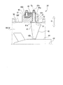
図2から図4に示すように、インレットガイドベーン24は、フレーム50と、複数の可動翼40と、軸受部60と、シール部70とを備えている。Next, the
As shown in FIGS. 2 to 4, the
フレーム50は、図2に示すように、円筒状をなしているベーンケースである。フレーム50は、ガス導入部23(図1参照)を構成する筒状体に接続される。これにより、ガス導入部23の内側を流れる流体Gの流路100の一部を形成する。フレーム50は、その外周部に、翼保持部51を有している。翼保持部51には、フレーム50の径方向Drに貫通する挿入孔51hが複数形成されている。挿入孔51hは、周方向に間隔をあけて形成されている。挿入孔51hは、可動翼40が取付可能とされている。具体的には、挿入孔51hは、後述する可動翼40の軸部42が挿入可能とされている。
As shown in FIG. 2, the
可動翼40は、フレーム50に対して回転可能に設けられている。可動翼40は、周方向に間隔をあけて複数設けられている。各可動翼40は、翼本体41と、軸部42と、を有する。
The
翼本体41は、フレーム50に対して径方向Dr内側(第一側)に設けられている。翼本体41は、その翼長方向を、フレーム50の径方向Drと一致させて配置されている。翼本体41は、径方向Dr内側に位置する端部41bが、フレーム50の中央部に設けられたセンターハブ44に対して隙間を空けた状態で、軸部42の中心軸Cs周りに回動可能とされている。
The
軸部42は、翼本体41に対して、径方向Dr外側(第二側)に位置する翼長方向の端部41aに一体に設けられている。軸部42は、その中心軸Csの延びる中心軸Cs方向に沿って延びる略円柱状をなしている。なお、本実施形態では、中心軸Cs方向は、径方向Drであり、翼長方向でもある。この軸部42は、フレーム50に形成された挿入孔51hに回転可能な状態で挿入されている。
The
図3に示すように、軸部42は、その先端部42sが、翼保持部51よりも径方向Dr外側に向かって突出している。この軸部42の先端部42sには、リンクプレート65の端部65aが、中心軸Cs周りに回動不能に固定されている。リンクプレート65の端部65bには、ドライブピン66が連結されている。このドライブピン66は、フレーム50の径方向Dr外側に設けられ、フレーム50の周方向に旋回可能に設けられた旋回リング67に、ドライブピン66の中心軸周りに回動自在に支持されている。この旋回リング67は、アクチュエータ26(図1参照)によりフレーム50の中心軸Cf(図2参照)周りに回動可能とされている。旋回リング67が、アクチュエータ26によって、中心軸Cf周りに旋回されると、リンクプレート65が軸部42を中心として揺動し、これによって軸部42がその中心軸Cs周りに回転する。これによって、フレーム50の内側の流路100における流体Gの流れ中において、翼本体41の角度(開度)が変わり、ガス導入部23を通過する流体Gの流量を制御する。
As shown in FIG. 3, the tip portion 42s of the
図4に示すように、軸受部60は、各可動翼40を支持するために、挿入孔51hの内部に設けられている。軸受部60は、フレーム50に形成された挿入孔51hに対して、その中心軸Cs周りに回転可能に軸部42を支持している。本実施形態の軸受部60は、軸部42の中心軸Cs方向に間隔をあけて複数設けられている。軸受部60は、筒状をなしている。本実施形態では、軸受部60として、第一軸受部60Aと第二軸受部60Bとの二つが設けられている。
As shown in FIG. 4, the bearing
軸部42を中心軸Cs周りに回動自在に支持する翼保持部51は、ベース部52と、複数のシール保持部材55と、中間部材56と、シール押さえ部材57と、を備える。
The
ベース部52は、フレーム50の外周面50fから径方向Dr外側に突出するよう形成されている。ベース部52は、フレーム50の径方向Dr外側を向くベース部52の外周面52fに、径方向Dr内側に窪んだ外周凹部(凹部)53を有している。また、フレーム50は、ベース部52が形成された部分に、その内周面50gからフレーム50の径方向Dr外側に窪んだ内周凹部54を有している。この内周凹部54は、可動翼40の翼本体41の端部41aの一部が収容される。
The
また、ベース部52には、フレーム50の径方向Drに沿って延びるベース部貫通孔52hが形成されている。ベース部貫通孔52hは、内周凹部54の底面54bと外周凹部53の底面53bとを貫通している。このベース部貫通孔52hは、挿入孔51hの一部を形成している。第一軸受部60Aは、このベース部貫通孔52hに対し、フレーム50の径方向Dr内側から外側に向かって嵌め込まれている。
Further, the
本実形態のシール保持部材55は、二つ設けられている。シール保持部材55は、ベース部52の外周凹部53内に、中心軸Cs方向に沿って積層された状態で収容されている。図5に示すように、シール保持部材55は、その中心軸Cs方向の中央部分に、挿入孔51hの一部を形成する保持部材貫通孔55hを有している。また、シール保持部材55は、後述する第一シール部材71を収容する収容部58を有している。
Two
収容部58は、シール保持部材55の中心軸Cs方向の保持部材第一面55f側に形成されている。収容部58は、保持部材貫通孔55hの孔径方向Ds外側で周方向に連続する環状で、中心軸Cs方向の保持部材第二面55g側に窪んで形成されている。ここで、保持部材第一面55fは、シール保持部材55において径方向Dr外側を向く面である。また、保持部材第二面55gは、シール保持部材55において径方向Dr内側を向く面である。収容部58は、保持部材貫通孔55hの内周側に臨む内周側段部58aと、内周側段部58aよりも保持部材第二面55g側への窪み寸法が小さい外周側段部58bと、を有している。外周側段部58bは、内周側段部58aの外周側と連続するように形成されている。
The
また、シール保持部材55は、保持部材第二面55g側に、周方向に連続して保持部材第一面55f側に窪む保持部材溝59を有している。この保持部材溝59は、中心軸Cs方向から見たときに、収容部58よりも孔径方向Ds外側に環状に形成されている。この保持部材溝59には、後述する第三シール部材79が収容される。
Further, the
中間部材56は、中心軸Cs方向の中間部材第二面56b側に、外周側に向かって延びるフランジ部56dを一体に有している。中間部材56は、このフランジ部56dをベース部52の外周凹部53内に挿入させている。中間部材56は、シール保持部材55に対し、径方向Drの外側に積層して設けられている。2枚のシール保持部材55と、中間部材56とは、その外周部がボルト61によってベース部52に締結されて共に固定されている。
The
ここで、中間部材第一面56aは、中間部材56において径方向Dr外側を向く面である。また、中間部材第二面56bは、中間部材56において径方向Dr内側を向く面である。
Here, the
中間部材56は、中心軸Cs方向の中間部材第一面56a側に、中心軸Cs方向の中間部材第二面56b側に向かって窪んだ中間凹部561を有している。また、中間部材56は、孔径方向Dsの中央部分に、中間凹部561と中間部材第二面56bとに貫通する中間部材貫通孔56hを有している。この中間部材貫通孔56hは、挿入孔51hの一部を形成している。
The
中間部材56は、中間部材貫通孔56hの孔径方向Ds外側に窪んだ孔側凹部562が形成されている。孔側凹部562は、中間部材貫通孔56hの中心軸Cs方向の中間部に、中心軸Cs周りの周方向に連続している。
The
なお、中間部材56に孔側凹部562が形成されずに、軸部42の外周面42fに孔径方向Ds内側に窪む軸側凹部が形成されていてもよい。したがって、孔側凹部562及び軸側凹部の少なくとも一方が形成されて、第一シール部材71と第二シール部材72との間に空間を広げるスペースが形成されていればよい。
The hole-
また、中間部材56は、中間部材第二面56b側に、周方向に連続して中間部材第一面56a側に窪む中間部材溝563を有している。この中間部材溝563は、中心軸Cs方向から見たときに、シール保持部材55に形成された収容部58よりも孔径方向Ds外側で環状に形成されている。この中間部材溝563には、後述する第三シール部材79が収容される。
Further, the
シール押さえ部材57は、中間部材56に対し、径方向Dr外側に配置されている。シール押さえ部材57は、中央部に、挿入孔51hの一部を形成する貫通孔57hが形成されている。第二軸受部60Bは、シール押さえ部材57に対し、フレーム50の径方向Dr外側から内側に向かって嵌め込まれている。シール押さえ部材57は、中心軸Cs方向の第二面57b側に、中間部材56の中間凹部561の内側に挿入される挿入筒部571を有している。シール押さえ部材57の挿入筒部571は、中間凹部561の内側に配置される第二シール部材72を、中間凹部561の底面561bとの間で挟み込む。
The
シール部70は、上記したような翼保持部51の挿入孔51hの内部に配置されている。シール部70は、中心軸Cs方向における複数の軸受部60の間に配置されている。このシール部70は、挿入孔51hと軸部42との間をシールし、フレーム50の内側から外側に、流路100から流体Gが流出することを抑えている。本実施形態のシール部70は、第一軸受部60Aと第二軸受部60Bとの間に設けられている。シール部70は、中心軸Cs方向に間隔をあけて配置された第一シール部材71と第二シール部材72とを有している。
The
第一シール部材71は、シール保持部材55の収容部58に収容されている。第一シール部材71は、二つのシール保持部材55にそれぞれ収容されている。つまり、第一シール部材71は、中心軸Cs方向において二重に設けられている。
The
第一シール部材71は、収容部58の内周側段部58aに収容される環状のシール部本体73と、シール部本体73から孔径方向Ds外側に延出しているリップ部76と、を有している。
The
シール部本体73は、軸部42の孔径方向Ds外側で周方向に連続している。シール部本体73は、弾性リング部74と、付勢部材75と、を備えている。リップ部76は、外周側段部58bに収容されている。
The seal portion
弾性リング部74は、軸部42の孔径方向Ds外側で周方向に連続する環状をなしている。弾性リング部74は、ゴム系材料等の弾性材料からなる。弾性リング部74は、フレーム50の径方向Dr内側に向かって開口するリング溝74mを有している。
The
付勢部材75は、径方向Dr内側に向かって開口する逆U字状に湾曲形成された板バネ材からなる。付勢部材75は、弾性リング部74のリング溝74m内に収容されている。付勢部材75は、弾性リング部74の内周面74fを挿入孔51hの孔径方向Ds内側に付勢している。
The urging
第二シール部材72は、中間部材56の中間凹部561に収容されている。第二シール部材72は、第一シール部材71よりも翼本体41に遠い位置に配置されている。つまり、二つの第一シール部材71は、挿入孔51hにおいて、第二シール部材72よりも翼本体41に近い位置に配置されている。第二シール部材72は、シールキャップ77と、シールリング78と、を備えている。
The
シールキャップ77は、円環状で、挿入孔51hの孔径方向Ds外側に向かって開口するキャップ溝77mを有している。シールリング78は、ゴム系材料からなる。シールリング78は、キャップ溝77m内に設けられている。シールリング78は、シールキャップ77を挿入孔51hの孔径方向Ds内側に向かって付勢している。
The
このようにして、第一シール部材71と、第二シール部材72とは、互いに異なるシール構造を有している。また、第二シール部材72よりも径方向Dr内側に配置される第一シール部材71は、第二シール部材72よりも高いシール性を有している。
In this way, the
なお、第一シール部材71と、第二シール部材72とは、互いに異なるシール構造であることに限定されるものではなく、同じシール構造であってもよい。
The
シール部70は、さらに、第三シール部材79を備える。第三シール部材79は、環状のゴム系材料からなるOリングである。第三シール部材79は、保持部材溝59と、中間部材溝563とに、それぞれ収容されている。保持部材溝59に収容された第三シール部材79Aは、シール保持部材55Aとこのシール保持部材55Aと対向するベース部52の外周凹部53の底面53bとの間をシールしている。中間部材溝563に収容された第三シール部材79Cは、この中間部材56とシール保持部材55Bとの間をシールする。
The
また、シール部70は、第一シール部材71と第二シール部材72との間に、シール空間80を備えている。このシール空間80は、第一シール部材71と第二シール部材72との間において、孔側凹部562によって、挿入孔51hと軸部42との間の隙間の断面積が拡大されることで形成されている。
Further, the
上述した実施形態のインレットガイドベーン24、遠心圧縮機システム1によれば、複数の第一軸受部60A及び第二軸受部60Bの間に配置されたシール部70によって、挿入孔51hと軸部42との間を通って流路100内の流体Gが漏れることを抑える。シール部70には、第一軸受部60A及び第二軸受部60Bと軸部42の外周面との間の隙間を通り抜けた流体のみが到達する。そのため、シール部70が流体に曝されにくくなり、流体に直接曝された状態で設けられている場合に比べて、流体の影響を受けにくくなる。したがって、シール部70の劣化を抑えて、高いシール性を継続して発揮させることができる。
According to the
また、シール部70に対して軸部42の中心軸Cs方向両側には、筒状の第一軸受部60A及び第二軸受部60Bが設けられている。この第一軸受部60A及び第二軸受部60Bに代えて、例えばボールベアリング等を設けた場合に比較し、軸部42の外周面42fと、第一軸受部60A及び第二軸受部60Bとの間の隙間は小さい。したがって、第一シール部材71には、第一軸受部60Aと軸部42の外周面42fとの隙間を通った流体Gのみが到達するので、第一シール部材71においてシール性を有効に発揮することができる。このようにして、可動翼40の軸部42におけるシール性を高めることが可能となる。
Further, tubular
また、シール部70を、第一シール部材71と第二シール部材72とによって二重の構成することで、シール性を高めることができる。さらに、第一シール部材71が二重に設けられているので、そのシール性がさらに高まる。
Further, by forming the
また、第一シール部材71と第二シール部材72とでシール構造を互いに異ならせることで、複数種のシール特性を有したシール部70が構成される。その結果、高いシール性が確保される。
Further, by making the seal structures of the
また、第一シール部材71は、第一シール部材71に対して翼本体41から離間する径方向Dr外側に配置される第二シール部材72よりも高いシール性を有している。このような構成によれば、流路100側からの流体Gの漏れを、第一シール部材71によって有効に抑えることができる。また、第二シール部材72は、第一シール部材71を通り抜けた流体Gのみをシールするバックアップとして機能させることができる。そのため、第二シール部材72のシール性を抑えても、シール部70全体としてのシール性を確保できる。その結果、第二シール部材72のコストを抑えることができる。
Further, the
また、第一シール部材71は、付勢部材75によって弾性リング部74の内周面74fを孔径方向Ds内側に付勢することで、第一シール部材71と軸部42との間のシール性を高めることができる。
Further, the
また、弾性リング部74のリング溝74mが、流体Gの流路100側である径方向Dr内側に開口しているので、流路100側から流体Gが漏れてきたときに、この流体Gがリング溝74m内に入り込む。流体Gがリング溝74m内に入り込むことによって、弾性リング部74の内周面74fが孔径方向Ds内側に押圧され、第一シール部材71と軸部42との間のシール性を高めることができる。
Further, since the
また、フレーム50は、中心軸Cs方向に沿って積層される複数のシール保持部材55を備えている。第一シール部材71は、各シール保持部材55の保持部材第一面55f側から収容部58に収容することができる。これにより、保持部材貫通孔55hの孔径方向Ds内側から外側に向かって第一シール部材71を組み付ける場合に比較すると、組付作業を容易に行うことができる。
Further, the
また、第一シール部材71は、シール部本体73から孔径方向Ds外側に延出するリップ部76が、この第一シール部材71が組み込まれたシール保持部材55と他の部材との間に挟み込まれるので、第一シール部材71が軸部42とともに連れ回ることを抑える。また、シール保持部材55と他の部材との隙間から流体Gが漏れることを抑える。
Further, in the
また、第一シール部材71の孔径方向Ds外側に配置した第三シール部材79によって、複数が積層されるシール保持部材55と他の部材との隙間から流体Gが漏出するのをさらに確実に抑えることができる。
Further, the
また、第一シール部材71と第二シール部材72との間に、孔側凹部562によって、シール空間80が形成されている。流路100側から流体Gが漏れてきたときに、この流体Gが、シール空間80に流れ込むことで、流体Gの漏出を抑えることができる。
Further, a
《第二実施形態》
次に、図6を参照して第二実施形態のインレットガイドベーンについて説明する。第二実施形態においては第一実施形態と同様の構成要素には同一の符号を付して詳細な説明を省略する。この第二実施形態のインレットガイドベーンは、シール部の構成について第一実施形態と相違する。<< Second Embodiment >>
Next, the inlet guide vane of the second embodiment will be described with reference to FIG. In the second embodiment, the same components as those in the first embodiment are designated by the same reference numerals, and detailed description thereof will be omitted. The inlet guide vane of the second embodiment differs from the first embodiment in the configuration of the seal portion.
即ち、図6に示すように、第二実施形態のインレットガイドベーン24Bは、上記第一実施形態のインレットガイドベーン24と同様に、フレーム50と、複数の可動翼40と、を備えている。
That is, as shown in FIG. 6, the
フレーム50は、その外周部に、翼保持部51を有している。翼保持部51は、周方向に間隔をあけて形成された複数個所に、フレーム50の径方向Drに沿って延びるよう形成された挿入孔51hを有している。
The
可動翼40は、挿入孔51hに設けられた第一軸受部60A及び第二軸受部60Bによって、軸部42が中心軸Cs周りに回動自在に支持されている。
In the
第一軸受部60A及び第二軸受部60Bの間には、シール部70Bが設けられている。シール部70Bの第一シール部材71と第二シール部材72との間には、中間部材56に形成された孔側凹部562によって、シール空間80Bが形成されている。
A
シール部70Bは、シール空間80Bに流路100内の流体Gが侵入したことを検知するセンサ90を備えている。センサ90は、流体Gが侵入したことを、シール空間80B内の圧力、温度、流体Gを構成する物質の検出等によって検知する。
The
上述したような構成によれば、上記第一実施形態と同様、可動翼40の軸部42におけるシール性を高めることができる。さらに、センサ90により、挿入孔51hと軸部42との隙間に流路100内から流体Gが漏れてきたことを検知することができる。これにより、センサ90で流体Gの漏出を検知した場合には、遠心圧縮機システム1の作動を停止させ、シール部70Bのメンテナンス等を適切なタイミングで行うことが可能となる。
According to the above-described configuration, the sealing property of the
《第三実施形態》
次に、図7を参照して第三実施形態のインレットガイドベーンについて説明する。第三実施形態においては、第一、第二実施形態と同様の構成要素には同一の符号を付して詳細な説明を省略する。この第三実施形態のインレットガイドベーンは、シール部の構成について第一、第二実施形態と相違する。<< Third Embodiment >>
Next, the inlet guide vane of the third embodiment will be described with reference to FIG. 7. In the third embodiment, the same components as those in the first and second embodiments are designated by the same reference numerals, and detailed description thereof will be omitted. The inlet guide vane of the third embodiment is different from the first and second embodiments in the configuration of the seal portion.
即ち、図7に示すように、第三実施形態のインレットガイドベーン24Cは、上記第一実施形態のインレットガイドベーン24と同様に、フレーム50と、複数の可動翼40と、を備えている。
That is, as shown in FIG. 7, the
フレーム50は、その外周部に、翼保持部51を有している。翼保持部51は、周方向に間隔をあけて形成された複数個所に、フレーム50の径方向Drに沿って延びるよう形成された挿入孔51hを有している。
The
可動翼40は、挿入孔51hに設けられた第一軸受部60A及び第二軸受部60Bによって、軸部42が中心軸Cs周りに回動自在に支持されている。
In the
第一軸受部60A及び第二軸受部60Bの間には、シール部70Cが設けられている。シール部70Cの第一シール部材71と第二シール部材72との間には、中間部材56に形成された孔側凹部562によって、シール空間80Cが形成されている。
A seal portion 70C is provided between the
中間部材56には、その外部と孔側凹部562とを連通する連通孔568が形成されている。この連通孔568には、シール用流体供給部95が接続されている。シール用流体供給部95は、挿入孔51hと軸部42との隙間のシール空間80Cに、外部からシール用流体Gsを供給する。
The
シール用流体供給部95は、シール用流体Gsを供給することで、シール空間80C内を加圧する。加圧されたシール空間80C内の圧力は、流路100内の圧力よりも低く、フレーム50の外部の圧力(大気圧)よりも高くなるようにするのが好ましい。
The sealing
上述したような構成によれば、上記第一実施形態と同様、可動翼40の軸部42におけるシール性を高めることができる。さらに、第一シール部材71と第二シール部材72との間のシール空間80Cに、外部からシール用流体Gsを送り込み、シール空間80C内を加圧する。これによって、流路100内の流体Gの圧力と、シール空間80C内の圧力との差圧が小さくなる。その結果、流路100内の流体Gが第一シール部材71と第二シール部材72との間に流れ込むことを抑え、シール性をさらに高めることができる。これにより、第一シール部材71が損傷することを抑える。
According to the above-described configuration, the sealing property of the
以上、本発明の実施形態について図面を参照して詳述したが、各実施形態における各構成及びそれらの組み合わせ等は一例であり、本発明の趣旨から逸脱しない範囲内で、構成の付加、省略、置換、及びその他の変更が可能である。また、本発明は実施形態によって限定されることはなく、特許請求の範囲によってのみ限定される。 Although the embodiments of the present invention have been described in detail with reference to the drawings, the configurations and combinations thereof in the respective embodiments are examples, and the configurations are added or omitted within the range not deviating from the gist of the present invention. , Replacement, and other changes are possible. Further, the present invention is not limited to the embodiments, but only to the scope of claims.
例えば、上記各実施形態で示したインレットガイドベーン24,24B、24Cは、遠心圧縮機システム1を構成するギアド圧縮機に限らず、軸流圧縮機等、ガスタービン等に適用することができる。
For example, the
上記したインレットガイドベーン、圧縮機によれば、インレットガイドベーンの可動翼の軸部におけるシール性を高めることができる。 According to the inlet guide vane and the compressor described above, it is possible to improve the sealing property of the inlet guide vane at the shaft portion of the movable blade.
1 遠心圧縮機システム
2 駆動軸
3 従動軸
4 圧縮部
5 第一従動軸
6 第二従動軸
7a、7b 第一段圧縮部(圧縮機)
8 第二段圧縮部
9 第三段圧縮部
10 増速機
11 駆動歯車
12 第一従動歯車
13 第二従動歯車
14 第一中間歯車
15 第二中間歯車
17 第一中間軸
18 第二中間軸
19 駆動源
20 ケーシング
23 ガス導入部
24、24B,24C インレットガイドベーン
25、37、38 インペラ
26 アクチュエータ
27 第一段熱交換器
27a 入口ノズル
27b 出口ノズル
28 第二段熱交換器
30 第一段配管
31a、31b 第一段圧縮部吐出配管
32 第二段圧縮部吸込配管
33 第二段配管
34 第二段圧縮部吐出配管
35 第三段圧縮部吸込配管
36 第三段圧縮部吐出配管
40 可動翼
41 翼本体
41a、41b 端部
42 軸部
42f 外周面
42s 先端部
44 センターハブ
50 フレーム
50f 外周面
50g 内周面
51 翼保持部
51f 内周面
51h 挿入孔
52 ベース部
52f 外周面
52h ベース部貫通孔
53 外周凹部
53b 底面
54 内周凹部
54b 底面
55、55A、55B シール保持部材
55f 保持部材第一面
55g 保持部材第二面
55h 保持部材貫通孔
56 中間部材
56a 中間部材第一面
56b 中間部材第二面
56d フランジ部
56h 中間部材貫通孔
561 中間凹部
561b 底面
562 孔側凹部
563 中間部材溝
568 連通孔
57 シール押さえ部材
57b 第二面
57h 貫通孔
571 挿入筒部
58 収容部
58a 内周側段部
58b 外周側段部
59 保持部材溝
60 軸受部
60A 第一軸受部
60B 第二軸受部
61 ボルト
65 リンクプレート
65a、65b 端部
66 ドライブピン
67 旋回リング
70、70B、70C シール部
71 第一シール部材
72 第二シール部材
73 シール部本体
74 弾性リング部
74f 内周面
74m リング溝
75 付勢部材
76 リップ部
77 シールキャップ
77m キャップ溝
78 シールリング
79、79A、79B、79C 第三シール部材
80、80B、80C シール空間
90 センサ
95 シール用流体供給部
100 流路
Cs 中心軸
Dr 径方向
Ds 孔径方向
G 流体
Gs シール用流体
P プラント1
8 Second-stage compression unit 9 Third-stage compression unit 10 Speed increaser 11 Drive gear 12 First driven gear 13 Second driven gear 14 First intermediate gear 15 Second intermediate gear 17 First intermediate shaft 18 Second intermediate shaft 19 Drive source 20 Casing 23 Gas introduction parts 24, 24B, 24C Inlet guide vanes 25, 37, 38 Impeller 26 Actuator 27 First-stage heat exchanger 27a Inlet nozzle 27b Outlet nozzle 28 Second-stage heat exchanger 30 First-stage piping 31a , 31b 1st stage compression part discharge pipe 32 2nd stage compression part suction pipe 33 2nd stage pipe 34 2nd stage compression part discharge pipe 35 3rd stage compression part suction pipe 36 3rd stage compression part discharge pipe 40 Movable blade 41 Wing body 41a, 41b End 42 Shaft 42f Outer peripheral surface 42s Tip 44 Center hub 50 Frame 50f Outer peripheral surface 50g Inner peripheral surface 51 Wing holding part 51f Inner peripheral surface 51h Insert hole 52 Base part 52f Outer peripheral surface 52h Base part through hole 53 Outer peripheral recess 53b Bottom 54 Inner peripheral recess 54b Bottom 55, 55A, 55B Seal holding member 55f Holding member first surface 55g Holding member second surface 55h Holding member through hole 56 Intermediate member 56a Intermediate member first surface 56b Intermediate member second Surface 56d Flange 56h Intermediate member through hole 561 Intermediate recess 561b Bottom surface 562 Hole side recess 563 Intermediate member groove 568 Communication hole 57 Seal holding member 57b Second surface 57h Through hole 571 Insertion cylinder 58 Storage 58a Inner peripheral side step 58b Outer peripheral side step portion 59 Holding member groove 60 Bearing portion 60A First bearing portion 60B Second bearing portion 61 Bolt 65 Link plate 65a, 65b End portion 66 Drive pin 67 Swivel ring 70, 70B, 70C Seal portion 71 First seal member 72 Second seal member 73 Seal part body 74 Elastic ring part 74f Inner peripheral surface 74m Ring groove 75 Bias member 76 Lip part 77 Seal cap 77m Cap groove 78 Seal ring 79, 79A, 79B, 79C Third seal member 80, 80B, 80C Seal space 90 Sensor 95 Sealing fluid supply 100 Flow path Cs Central axis Dr Radial direction Ds Pore radial direction G Fluid Gs Sealing fluid P Plant
Claims (6)
前記軸部が挿入される挿入孔が形成されたフレームと、
前記挿入孔の内部で前記軸部の中心軸方向に間隔をあけて複数設けられ、前記フレームに対して前記中心軸周りに回転可能に前記軸部を支持する軸受部と、
前記挿入孔の内部で前記中心軸方向における複数の前記軸受部の間に配置され、前記挿入孔と前記軸部との間をシールするシール部と、を備え、
前記シール部は、前記中心軸方向に間隔をあけて配置された第一シール部材と第二シール部材とを備え、
前記第一シール部材と前記第二シール部材とは、互いに異なるシール構造を有し、
前記シール部は、
前記軸部の径方向外側で周方向に連続する環状をなし、前記フレームに対して前記翼本体が配置されている側に向かって開口する溝が形成された弾性リング部と、
前記溝に設けられ、前記弾性リング部の内周面を前記軸部に向かって径方向内側に付勢する付勢部材と、を備えるインレットガイドベーン。 A wing body and a movable wing having a shaft portion provided at the end of the wing body,
A frame in which an insertion hole into which the shaft portion is inserted is formed, and
A plurality of bearing portions provided inside the insertion hole at intervals in the central axis direction of the shaft portion, and a bearing portion that rotatably supports the shaft portion around the central axis with respect to the frame.
A seal portion that is arranged inside the insertion hole between the plurality of bearing portions in the central axial direction and seals between the insertion hole and the shaft portion is provided.
The seal portion includes a first seal member and a second seal member arranged at intervals in the central axis direction.
Wherein the first sealing member and the second sealing member, possess different seal structure from each other,
The seal portion is
An elastic ring portion having an annular shape continuous in the circumferential direction on the radial outer side of the shaft portion and having a groove formed in the frame toward the side where the blade body is arranged.
An inlet guide vane provided in the groove and comprising an urging member for urging the inner peripheral surface of the elastic ring portion radially inward toward the shaft portion .
前記第二シール部材よりも前記翼本体に近い位置に配置され、
前記第二シール部材よりも高いシール性を有する請求項1に記載のインレットガイドベーン。 The first seal member is
It is arranged at a position closer to the wing body than the second seal member.
The inlet guide vane according to claim 1, which has a higher sealing property than the second sealing member.
Applications Claiming Priority (1)
| Application Number | Priority Date | Filing Date | Title |
|---|---|---|---|
| PCT/JP2017/004184 WO2018142606A1 (en) | 2017-02-06 | 2017-02-06 | Inlet guide vane and compressor |
Publications (2)
| Publication Number | Publication Date |
|---|---|
| JPWO2018142606A1 JPWO2018142606A1 (en) | 2019-11-07 |
| JP6810168B2 true JP6810168B2 (en) | 2021-01-06 |
Family
ID=63041196
Family Applications (1)
| Application Number | Title | Priority Date | Filing Date |
|---|---|---|---|
| JP2018565218A Active JP6810168B2 (en) | 2017-02-06 | 2017-02-06 | Inlet guide vanes and compressors |
Country Status (4)
| Country | Link |
|---|---|
| US (1) | US11041401B2 (en) |
| EP (1) | EP3550154B1 (en) |
| JP (1) | JP6810168B2 (en) |
| WO (1) | WO2018142606A1 (en) |
Families Citing this family (4)
| Publication number | Priority date | Publication date | Assignee | Title |
|---|---|---|---|---|
| CN110374891B (en) * | 2019-08-19 | 2021-03-23 | 重庆美的通用制冷设备有限公司 | Centrifugal compressor |
| CN111664110B (en) * | 2020-05-25 | 2021-09-07 | 中国科学院工程热物理研究所 | Compressor inlet guide vane adjusting mechanism and control method thereof |
| JP2022094019A (en) | 2020-12-14 | 2022-06-24 | 三菱重工コンプレッサ株式会社 | Rotary machine |
| CN114483629B (en) * | 2022-01-13 | 2023-07-28 | 江苏海拓宾未来工业科技集团有限公司 | Multi-shaft multi-stage hydrogen fuel high-speed centrifugal compressor |
Family Cites Families (12)
| Publication number | Priority date | Publication date | Assignee | Title |
|---|---|---|---|---|
| JPS61215499A (en) * | 1985-03-22 | 1986-09-25 | Ebara Corp | Capacity control device for centrifugal compressor |
| US5622473A (en) * | 1995-11-17 | 1997-04-22 | General Electric Company | Variable stator vane assembly |
| US6210106B1 (en) | 1999-04-30 | 2001-04-03 | General Electric Company | Seal apparatus for gas turbine engine variable vane |
| US6767183B2 (en) * | 2002-09-18 | 2004-07-27 | General Electric Company | Methods and apparatus for sealing gas turbine engine variable vane assemblies |
| US7207770B2 (en) * | 2003-05-27 | 2007-04-24 | General Electric Company | Variable stator vane bushings and washers |
| US7445427B2 (en) | 2005-12-05 | 2008-11-04 | General Electric Company | Variable stator vane assembly and bushing thereof |
| FR2902822B1 (en) * | 2006-06-21 | 2008-08-22 | Snecma Sa | STATOR BEARING FOR STATOR WITH VARIABLE SHAFT |
| CN102713304B (en) | 2009-11-03 | 2015-01-28 | 英格索尔-兰德公司 | Inlet guide vane for a compressor |
| JP6185781B2 (en) | 2013-07-23 | 2017-08-23 | 三菱日立パワーシステムズ株式会社 | Axial flow compressor |
| CN105765277B (en) | 2013-12-10 | 2017-11-17 | 日本精工株式会社 | Sealing mechanism, the drive device of sealing mechanism, conveying device and manufacture device |
| JP6015715B2 (en) * | 2013-12-10 | 2016-10-26 | 日本精工株式会社 | SEALING MECHANISM, SEALING MECHANISM DRIVE DEVICE, CONVEYING DEVICE, AND MANUFACTURING DEVICE |
| US9903451B2 (en) | 2014-10-31 | 2018-02-27 | Trane International Inc. | Linkage to actuate inlet guide vanes |
-
2017
- 2017-02-06 US US16/475,883 patent/US11041401B2/en active Active
- 2017-02-06 EP EP17894791.7A patent/EP3550154B1/en active Active
- 2017-02-06 JP JP2018565218A patent/JP6810168B2/en active Active
- 2017-02-06 WO PCT/JP2017/004184 patent/WO2018142606A1/en active Application Filing
Also Published As
| Publication number | Publication date |
|---|---|
| US11041401B2 (en) | 2021-06-22 |
| US20190376409A1 (en) | 2019-12-12 |
| WO2018142606A1 (en) | 2018-08-09 |
| JPWO2018142606A1 (en) | 2019-11-07 |
| EP3550154A4 (en) | 2019-12-18 |
| EP3550154B1 (en) | 2021-01-06 |
| EP3550154A1 (en) | 2019-10-09 |
Similar Documents
| Publication | Publication Date | Title |
|---|---|---|
| JP6810168B2 (en) | Inlet guide vanes and compressors | |
| JP5231611B2 (en) | Compressor | |
| US8616554B2 (en) | Low and reverse pressure application hydrodynamic pressurizing seals | |
| JP5017052B2 (en) | Screw fluid machine | |
| JP5791779B2 (en) | gas turbine | |
| JP5769332B2 (en) | Scroll expander | |
| CN105874247B (en) | Shaft sealer and rotating machinery | |
| EP3456980B1 (en) | Compressor | |
| JP5180789B2 (en) | Gas seal structure of centrifugal compressor with built-in gearbox | |
| US20080217861A1 (en) | Coaxial Multi-Shaft Assemblies | |
| EP3118457B1 (en) | Oil-free screw compressor | |
| US11209009B2 (en) | Rotating machine | |
| JP4930901B2 (en) | Mechanical seal for turbo pump | |
| JP7429541B2 (en) | compressor system | |
| JP5425009B2 (en) | Fluid machinery | |
| JP2016044760A (en) | Shaft seal device | |
| JP5931696B2 (en) | Rotating machine | |
| JP2018021554A (en) | Axial flow turbine of turbocharger and turbocharger | |
| JP6973981B2 (en) | Fluid machinery, especially compressor equipment | |
| JP4370232B2 (en) | Fluid machine with fluid seal mechanism | |
| JP2009250151A (en) | Thrust reduction device of axial flow turbine | |
| JP2010014051A (en) | Centrifugal compressor | |
| US10227887B2 (en) | Fluid machine with variable vanes | |
| JP2018044539A (en) | Scroll expander |
Legal Events
| Date | Code | Title | Description |
|---|---|---|---|
| A621 | Written request for application examination |
Free format text: JAPANESE INTERMEDIATE CODE: A621 Effective date: 20190628 |
|
| A131 | Notification of reasons for refusal |
Free format text: JAPANESE INTERMEDIATE CODE: A131 Effective date: 20200421 |
|
| A521 | Request for written amendment filed |
Free format text: JAPANESE INTERMEDIATE CODE: A523 Effective date: 20200617 |
|
| A131 | Notification of reasons for refusal |
Free format text: JAPANESE INTERMEDIATE CODE: A131 Effective date: 20200825 |
|
| A521 | Request for written amendment filed |
Free format text: JAPANESE INTERMEDIATE CODE: A523 Effective date: 20201022 |
|
| TRDD | Decision of grant or rejection written | ||
| A01 | Written decision to grant a patent or to grant a registration (utility model) |
Free format text: JAPANESE INTERMEDIATE CODE: A01 Effective date: 20201201 |
|
| A61 | First payment of annual fees (during grant procedure) |
Free format text: JAPANESE INTERMEDIATE CODE: A61 Effective date: 20201210 |
|
| R150 | Certificate of patent or registration of utility model |
Ref document number: 6810168 Country of ref document: JP Free format text: JAPANESE INTERMEDIATE CODE: R150 |