EP3550154B1 - Inlet guide vane and compressor - Google Patents
Inlet guide vane and compressor Download PDFInfo
- Publication number
- EP3550154B1 EP3550154B1 EP17894791.7A EP17894791A EP3550154B1 EP 3550154 B1 EP3550154 B1 EP 3550154B1 EP 17894791 A EP17894791 A EP 17894791A EP 3550154 B1 EP3550154 B1 EP 3550154B1
- Authority
- EP
- European Patent Office
- Prior art keywords
- seal
- seal member
- inlet guide
- shaft portion
- guide vane
- Prior art date
- Legal status (The legal status is an assumption and is not a legal conclusion. Google has not performed a legal analysis and makes no representation as to the accuracy of the status listed.)
- Active
Links
Images


Classifications
-
- F—MECHANICAL ENGINEERING; LIGHTING; HEATING; WEAPONS; BLASTING
- F01—MACHINES OR ENGINES IN GENERAL; ENGINE PLANTS IN GENERAL; STEAM ENGINES
- F01D—NON-POSITIVE DISPLACEMENT MACHINES OR ENGINES, e.g. STEAM TURBINES
- F01D17/00—Regulating or controlling by varying flow
- F01D17/10—Final actuators
- F01D17/12—Final actuators arranged in stator parts
- F01D17/14—Final actuators arranged in stator parts varying effective cross-sectional area of nozzles or guide conduits
- F01D17/16—Final actuators arranged in stator parts varying effective cross-sectional area of nozzles or guide conduits by means of nozzle vanes
- F01D17/162—Final actuators arranged in stator parts varying effective cross-sectional area of nozzles or guide conduits by means of nozzle vanes for axial flow, i.e. the vanes turning around axes which are essentially perpendicular to the rotor centre line
-
- F—MECHANICAL ENGINEERING; LIGHTING; HEATING; WEAPONS; BLASTING
- F04—POSITIVE - DISPLACEMENT MACHINES FOR LIQUIDS; PUMPS FOR LIQUIDS OR ELASTIC FLUIDS
- F04D—NON-POSITIVE-DISPLACEMENT PUMPS
- F04D25/00—Pumping installations or systems
- F04D25/16—Combinations of two or more pumps ; Producing two or more separate gas flows
- F04D25/163—Combinations of two or more pumps ; Producing two or more separate gas flows driven by a common gearing arrangement
-
- F—MECHANICAL ENGINEERING; LIGHTING; HEATING; WEAPONS; BLASTING
- F04—POSITIVE - DISPLACEMENT MACHINES FOR LIQUIDS; PUMPS FOR LIQUIDS OR ELASTIC FLUIDS
- F04D—NON-POSITIVE-DISPLACEMENT PUMPS
- F04D29/00—Details, component parts, or accessories
- F04D29/05—Shafts or bearings, or assemblies thereof, specially adapted for elastic fluid pumps
- F04D29/056—Bearings
- F04D29/057—Bearings hydrostatic; hydrodynamic
-
- F—MECHANICAL ENGINEERING; LIGHTING; HEATING; WEAPONS; BLASTING
- F04—POSITIVE - DISPLACEMENT MACHINES FOR LIQUIDS; PUMPS FOR LIQUIDS OR ELASTIC FLUIDS
- F04D—NON-POSITIVE-DISPLACEMENT PUMPS
- F04D29/00—Details, component parts, or accessories
- F04D29/08—Sealings
- F04D29/083—Sealings especially adapted for elastic fluid pumps
-
- F—MECHANICAL ENGINEERING; LIGHTING; HEATING; WEAPONS; BLASTING
- F04—POSITIVE - DISPLACEMENT MACHINES FOR LIQUIDS; PUMPS FOR LIQUIDS OR ELASTIC FLUIDS
- F04D—NON-POSITIVE-DISPLACEMENT PUMPS
- F04D29/00—Details, component parts, or accessories
- F04D29/40—Casings; Connections of working fluid
- F04D29/42—Casings; Connections of working fluid for radial or helico-centrifugal pumps
- F04D29/44—Fluid-guiding means, e.g. diffusers
- F04D29/46—Fluid-guiding means, e.g. diffusers adjustable
- F04D29/462—Fluid-guiding means, e.g. diffusers adjustable especially adapted for elastic fluid pumps
-
- F—MECHANICAL ENGINEERING; LIGHTING; HEATING; WEAPONS; BLASTING
- F04—POSITIVE - DISPLACEMENT MACHINES FOR LIQUIDS; PUMPS FOR LIQUIDS OR ELASTIC FLUIDS
- F04D—NON-POSITIVE-DISPLACEMENT PUMPS
- F04D29/00—Details, component parts, or accessories
- F04D29/40—Casings; Connections of working fluid
- F04D29/52—Casings; Connections of working fluid for axial pumps
- F04D29/54—Fluid-guiding means, e.g. diffusers
- F04D29/56—Fluid-guiding means, e.g. diffusers adjustable
- F04D29/563—Fluid-guiding means, e.g. diffusers adjustable specially adapted for elastic fluid pumps
-
- F—MECHANICAL ENGINEERING; LIGHTING; HEATING; WEAPONS; BLASTING
- F05—INDEXING SCHEMES RELATING TO ENGINES OR PUMPS IN VARIOUS SUBCLASSES OF CLASSES F01-F04
- F05D—INDEXING SCHEME FOR ASPECTS RELATING TO NON-POSITIVE-DISPLACEMENT MACHINES OR ENGINES, GAS-TURBINES OR JET-PROPULSION PLANTS
- F05D2220/00—Application
- F05D2220/30—Application in turbines
- F05D2220/32—Application in turbines in gas turbines
-
- F—MECHANICAL ENGINEERING; LIGHTING; HEATING; WEAPONS; BLASTING
- F05—INDEXING SCHEMES RELATING TO ENGINES OR PUMPS IN VARIOUS SUBCLASSES OF CLASSES F01-F04
- F05D—INDEXING SCHEME FOR ASPECTS RELATING TO NON-POSITIVE-DISPLACEMENT MACHINES OR ENGINES, GAS-TURBINES OR JET-PROPULSION PLANTS
- F05D2250/00—Geometry
- F05D2250/50—Inlet or outlet
- F05D2250/51—Inlet
Definitions
- This invention relates to an inlet guide vane and a compressor.
- a centrifugal compressor circulates a fluid inside a rotating impeller, and compresses the fluid in a gaseous state by utilizing a centrifugal force generated when the impeller is rotated.
- This centrifugal compressor includes a variable type inlet guide vane (IGV) which can adjust a flow rate of the fluid introduced from the outside by changing an angle of an inlet guide vane in order to broaden an operation range of the centrifugal compressor.
- IIGV variable type inlet guide vane
- the inlet guide vane is disposed in an inlet flow path which introduces the fluid from the outside into a housing of the centrifugal compressor.
- the inlet guide vane includes a vane case fixed at the inlet flow path, and a plurality of movable vanes which are supported by the vane case and whose opening degree can be adjusted.
- Each of the movable vanes has a vane main body and a shaft portion integrally formed with the vane main body. In the movable vane, the shaft portion is supported by a shaft hole formed in the vane case so as to be rotatable via a bearing of a bush.
- a minute clearance is formed between the bearing and the shaft portion so that the shaft portion of the movable vane is rotatable inside the shaft hole. Through this minute clearance, the fluid leaks outward.
- Patent Document 1 discloses a configuration where a seal member is provided in order to prevent the fluid from flowing out through the clearance of the shaft portion of the movable vane.
- the present invention provides an inlet guide vane and a compressor which can improve sealing performance in a shaft portion of a movable vane.
- an inlet guide vane including a movable vane that has a vane main body and a shaft portion disposed in an end portion of the vane main body, a frame that has an insertion hole into which the shaft portion is to be inserted, a plurality of bearing portions that are arranged inside the insertion hole at an interval in a direction of a central axis of the shaft portion, and that support the shaft portion so as to be rotatable around the central axis with respect to the frame, and a seal portion that is located inside the insertion hole between the plurality of bearing portions in the direction of the central axis, and that is configured to seal between the insertion hole and the shaft portion.
- the seal portion located between the plurality of bearing portions prevents a fluid inside a flow path from leaking outward after passing between an inner peripheral surface of the insertion hole and an outer peripheral surface of the shaft portion. Only the fluid passing through a clearance between the bearing portion and the outer peripheral surface of the shaft portion arrives at the seal portion. Accordingly, the seal portion is less likely to be exposed to the fluid, and is less likely to be affected by the fluid. Therefore, it is possible to continuously achieve high sealing performance by preventing the seal portion from being degraded.
- the seal portion includes a first seal member and a second seal member which are located at an interval in the direction of the central axis.
- the first seal member and the second seal member allow the seal portion to have a double configuration. Therefore, the sealing performance can be improved.
- the first seal member and the second seal member may have seal structures which are different from each other.
- the first seal member and the second seal member are caused to have mutually different seal structures, thereby configuring the seal portion having a plurality of sealing characteristics. As a result, higher sealing performance is ensured.
- the first seal member may be located at a position closer to the vane main body than the second seal member, and may have sealing performance higher than that of the second seal member.
- the first seal member having the high sealing performance can effectively prevent the fluid from leaking out of the vane main body side. Furthermore, the second seal member is caused to function as a backup member for sealing the clearance against only the fluid passing through the first seal member. In this manner, even if the sealing performance of the second seal member is suppressed, the sealing performance of the seal portion can be ensured as a whole. As a result, cost for the second seal member can be minimized.
- At least any one of a hole side recess portion formed on an inner peripheral surface of the insertion hole and recessed outward in a radial direction and a shaft side recess portion formed on an outer peripheral surface of the shaft portion and recessed inward in the radial direction may be formed between the first seal member and the second seal member.
- a space is formed in which a cross-sectional area of the clearance between the inner peripheral surface of the insertion hole and the outer peripheral surface of the shaft portion is widened by at least one of the hole side recess portion and the shaft side recess portion. Therefore, even in a case where the fluid leaks out of the flow path side, the fluid is reserved in this space, and the fluid can be prevented from leaking outward. In this manner, for example, even if the fluid flows in from the first seal member side and the sealing performance is degraded in the first seal member, the sealing performance as the whole seal portion can be prevented from being degraded.
- the inlet guide vane may include a sensor that is disposed between the first seal member and the second seal member, and that is configured to detect a fluid entering a clearance between an inner peripheral surface of the insertion hole and an outer peripheral surface of the shaft portion.
- the sensor can detect that the fluid leaks out of the flow path side.
- the inlet guide vane may further include a sealing fluid supply unit that is disposed between the first seal member and the second seal member, and that is configured to supply a sealing fluid from the outside to a clearance between an inner peripheral surface of the insertion hole and an outer peripheral surface of the shaft portion.
- a sealing fluid supply unit that is disposed between the first seal member and the second seal member, and that is configured to supply a sealing fluid from the outside to a clearance between an inner peripheral surface of the insertion hole and an outer peripheral surface of the shaft portion.
- the sealing fluid is fed from the outside to a portion between the first seal member and the second seal member.
- the fluid inside the flow path can be prevented from flowing into the portion between the first seal member and the second seal member.
- the seal portion may include an elastic ring portion which is disposed outward in a radial direction of the shaft portion, which has an annular shape continuous in a circumferential direction, and which has a groove open toward a side where the vane main body is located with respect to the frame, and a biasing member which is disposed in the groove, and which is configured to cause an inner peripheral surface of the elastic ring portion to be biased inward in the radial direction toward the shaft portion.
- the inner peripheral surface of the elastic ring portion is biased inward in the radial direction by the biasing member. Accordingly, the sealing performance between the seal portion and the shaft portion can be improved.
- the groove of the elastic ring portion is open to the side where the vane main body on the flow path side of the fluid is located. Therefore, when the fluid leaks out of the flow path side, the fluid flows into the groove. Since the fluid flows into the groove, the inner peripheral surface of the elastic ring portion is pressed inward in the radial direction. Therefore, the sealing performance between the seal portion and the shaft portion can be improved.
- the seal portion located between the plurality of bearing portions prevents the fluid inside the flow path from leaking outward after passing between the inner peripheral surface of the insertion hole and the outer peripheral surface of the shaft portion suppress.
- the inlet guide vane is also effectively applicable to the compressor in which flammable gas is used as the fluid.
- a centrifugal compressor system 1 includes a drive source 19 for generating power, a drive shaft 2, a driven shaft 3, a compression unit 4, and a speed increaser 10.
- the drive shaft 2 is driven to be rotatable around a central axis thereof by the drive source 19.
- the drive source 19 a steam turbine or a motor can be used.
- the driven shaft 3 is driven to be rotatable around the central axis by the power transmitted from the speed increaser 10.
- the driven shafts 3 are respectively located on both sides across the drive shaft 2.
- the driven shaft 3 has a first driven shaft 5 and a second driven shaft 6 which respectively extend parallel to the drive shaft 2.
- the speed increaser 10 increases rotation speed of the drive shaft 2, and transmits the rotation speed to the first driven shaft 5 and the second driven shaft 6.
- the speed increaser 10 includes a drive gear 11, a first driven gear 12, a second driven gear 13, a first intermediate gear 14, and a second intermediate gear 15.
- the drive gear 11 is disposed in a tip portion of the drive shaft 2 inserted into the casing 20 after penetrating the casing 20, and is rotated integrally with the drive shaft 2.
- the drive shaft 2 is supported by the casing 20 via a bearing (not shown).
- the first driven gear 12 is disposed integrally with the first driven shaft 5 in the intermediate portion in the direction of the central axis of the first driven shaft 5.
- the second driven gear 13 is disposed integrally with the second driven shaft 6 in the intermediate portion in the direction of the central axis of the second driven shaft 6.
- the first driven shaft 5 and the second driven shaft 6 are supported by the casing 20 via a bearing (not shown).
- the first driven gear 12 and the second driven gear 13 are located on both sides across the drive gear 11 at an interval therebetween.
- the first intermediate gear 14 is located between the drive gear 11 and the first driven gear 12, and meshes with the drive gear 11 and the first driven gear 12.
- the second intermediate gear 15 is located between the drive gear 11 and the second driven gear 13 and meshes with the drive gear 11 and the second driven gear 13.
- the first intermediate gear 14 and the second intermediate gear 15 are so-called idle gears.
- the first intermediate gear 14 is disposed integrally with a first intermediate shaft 17 rotatably supported by the casing 20 via a bearing (not shown).
- the second intermediate gear 15 is disposed integrally with a second intermediate shaft 18 rotatably supported by the casing 20 via a bearing (not shown).
- the drive gear 11 is rotated integrally with the drive shaft 2.
- the rotation of the drive gear 11 is transmitted to the first driven gear 12 and the second driven gear 13 via the first intermediate gear 14 and the second intermediate gear 15.
- the first driven gear 12 and the second driven gear 13 are rotated.
- the first driven shaft 5 is rotated.
- the second driven shaft 6 is rotated. That is, since the drive shaft 2 is driven, the first driven shaft 5 and the second driven shaft 6 are rotated.
- the compression unit 4 is driven by power transmitted from the drive shaft 2 to the driven shaft 3 via the speed increaser 10.
- the compression unit 4 includes two first stage compression units (compressors) 7a and 7b, a second stage compression unit 8, and a third stage compression unit 9.
- the first stage compression units 7a and 7b are compression units into which a fluid G initially flows in the centrifugal compressor system 1.
- the first stage compression units 7a and 7b are respectively disposed in end portions on both sides in the direction of the central axis of the first driven shaft 5.
- the two first stage compression units 7a and 7b have the same configuration.
- the first stage compression units 7a and 7b according to the present embodiment respectively have a gas inlet 23, an inlet guide vane 24, and an impeller 25.
- the gas inlet 23 has a continuous cylindrical shape.
- the gas inlet 23 internally forms an inlet flow path which introduces the fluid G serving as a compression target from the outside.
- the impeller 25 is attached to the first driven shaft 5, and compresses the fluid G supplied from the gas inlet 23.
- the inlet guide vane 24 is disposed in the gas inlet 23.
- the inlet guide vane 24 controls a flow rate of the fluid G passing through the gas inlet 23.
- the second stage compression unit 8 is disposed in end portion on a side opposite to a side where the drive source 19 is disposed in the second driven shaft 6.
- the second stage compression unit 8 has an impeller 37 for compressing the fluid G.
- the third stage compression unit 9 is disposed on a side which is the same as the side where the drive source 19 is disposed in the second driven shaft 6.
- the third stage compression unit 9 has an impeller 38 for compressing the fluid G.
- the two first stage compression units 7a and 7b are connected to the second stage compression unit 8 via a first stage pipe 30.
- the first stage pipe 30 is configured to include two first stage compression unit discharge pipes 31a and 31b and a second stage compression unit suction pipe 32.
- a first stage heat exchanger 27 is interposed between the first stage compression unit discharge pipes 31a and 31b and the second stage compression unit suction pipe 32.
- the first stage heat exchanger 27 includes two inlet nozzles 27a and one outlet nozzle 27b.
- the first stage compression unit discharge pipes 31a and 31b are respectively connected to the two inlet nozzles 27a.
- the second stage compression unit suction pipe 32 is connected to the outlet nozzle 27b. That is, the first stage heat exchanger 27 has a function to cool the double system fluid G discharged from the two first stage compression units 7a and 7b configuring the first stage compression units 7a and 7b, and to merge the double system fluid G so as to be the single system fluid G.
- the fluid G is intermediately cooled by the first stage heat exchanger 27 during a compression process. Accordingly, power needed to drive the centrifugal compressor system 1 is reduced.
- the second stage compression unit 8 is connected to the third stage compression unit 9 via the second stage pipe 33.
- the second stage pipe 33 is configured to include a second stage compression unit discharge pipe 34 and a third stage compression unit suction pipe 35.
- a second stage heat exchanger 28 for cooling the fluid G discharged from the second stage compression unit 8 is disposed between the second stage compression unit discharge pipe 34 and the third stage compression unit suction pipe 35.
- the fluid G is intermediately cooled by the second stage heat exchanger 28 during the compression process. Accordingly, the power needed to drive the centrifugal compressor system 1 is reduced.
- the third stage compression unit discharge pipe 36 is connected to the impeller 38 of the third stage compression unit 9.
- the third stage compression unit discharge pipe 36 is connected to a predetermined plant P serving as a supply destination of the fluid G.
- the fluid G to be compressed is introduced from the two gas inlets 23 and 23 configuring the first stage compression units 7a and 7b, and is compressed in the two first stage compression units 7a and 7b.
- the fluid G compressed in the first stage compression units 7a and 7b passes through the first stage compression unit discharge pipes 31a and 31b, and merges after being introduced to the first stage heat exchanger 27.
- the merged fluid G is introduced to the second stage compression unit 8 through the second stage compression unit suction pipe 32 after the being intermediately cooled by the first stage heat exchanger 27.
- the fluid G is compressed in the second stage compression unit 8. Thereafter, the fluid G is fed to the second stage heat exchanger 28 through the second stage compression unit discharge pipe 34. In the second stage heat exchanger 28, the fed fluid G is intermediately cooled. The intermediately cooled fluid G is introduced into the third stage compression unit 9 through the third stage compression unit suction pipe 35.
- the fluid G After being compressed in the third stage compression unit 9, the fluid G is supplied to the predetermined plant P serving as a demand destination of the compressed fluid G through the third stage compression unit discharge pipe 36.
- the inlet guide vane 24 includes a frame 50, a plurality of movable vanes 40, a bearing portion 60, and a seal portion 70.
- the frame 50 is a vane case having a cylindrical shape.
- the frame 50 is connected to a cylindrical body configuring the gas inlet 23 (refer to FIG. 1 ). In this manner, a portion of a flow path 100 of the fluid G flowing inside the gas inlet 23 is formed.
- An outer peripheral portion of the frame 50 has a vane holder 51.
- a plurality of insertion holes 51h penetrating the frame 50 in a radial direction Dr are formed in the vane holder 51.
- the insertion holes 51h are formed at an interval in the circumferential direction.
- the movable vane 40 can be attached to the insertion hole 51h. Specifically, a shaft portion 42 (to be described later) of the movable vane 40 can be inserted into the insertion hole 51h.
- the movable vane 40 is rotatably disposed with respect to the frame 50.
- the plurality of movable vanes 40 are disposed at an interval in the circumferential direction.
- Each of the movable vanes 40 has a vane main body 41 and the shaft portion 42.
- the vane main body 41 is disposed on the inner side (first side) in the radial direction Dr with respect to the frame 50.
- the vane main body 41 is located by aligning a vane length direction thereof with the radial direction Dr of the frame 50.
- the vane main body 41 is rotatable around a central axis Cs of the shaft portion 42.
- the shaft portion 42 is disposed integrally with the end portion 41a in the vane length direction which is located on the outer side (second side) in the radial direction Dr with respect to the vane main body 41.
- the shaft portion 42 has a substantially cylindrical shape extending along the direction of the extending central axis Cs of the central axis Cs.
- the direction of the central axis Cs is the radial direction Dr, and is also the vane length direction.
- the shaft portion 42 is inserted into the insertion hole 51h formed in the frame 50.
- a tip portion 42s of the shaft portion 42 protrudes outward in the radial direction Dr from the vane holder 51.
- An end portion 65a of a link plate 65 is fixed to the tip portion 42s of the shaft portion 42 so that the end portion 65a is not rotatable around the central axis Cs.
- a drive pin 66 is connected to an end portion 65b of the link plate 65.
- the drive pin 66 is disposed on the outer side in the radial direction Dr of the frame 50, and is supported so as to be rotatable around the central axis of the drive pin 66 by a turning ring 67 disposed so as to be capable of turning in the circumferential direction of the frame 50.
- the turning ring 67 is rotatable around a central axis Cf (refer to FIG. 2 ) of the frame 50 by an actuator 26 (refer to FIG. 1 ). If the turning ring 67 is turned around the central axis Cf by the actuator 26, the link plate 65 oscillates around the shaft portion 42 as a center. In this manner, the shaft portion 42 is rotated around the central axis Cs. In this manner, an angle (opening degree) of the vane main body 41 is changed in the flow of the fluid G in the flow path 100 inside the frame 50, and a flow rate of the fluid G passing through the gas inlet 23 is controlled.
- the bearing portion 60 is disposed inside the insertion hole 51h in order to support each of the movable vanes 40.
- the bearing portion 60 supports the shaft portion 42 so as to be rotatable around the central axis Cs with respect to the insertion hole 51h formed in the frame 50.
- the plurality of bearing portions 60 according to the present embodiment are disposed at an interval in the direction of the central axis Cs of the shaft portion 42.
- the bearing portion 60 has a cylindrical shape. According to the present embodiment, as the bearing portion 60, two of a first bearing portion 60A and a second bearing portion 60B are disposed therein.
- the vane holder 51 supporting the shaft portion 42 so as to be rotatable around the central axis Cs includes a base portion 52, a plurality of seal holding members 55, an intermediate member 56, and a seal pressure member 57.
- the base portion 52 is formed so as to protrude outward in the radial direction Dr from an outer peripheral surface 50f of the frame 50.
- the base portion 52 has an outer peripheral recess portion (recess portion) 53 recessed inward in the radial direction Dr on an outer peripheral surface 52f of the base portion 52 facing outward in the radial direction Dr of the frame 50.
- a portion where the base portion 52 is formed has an inner peripheral recess portion 54 recessed outward in the radial direction Dr of the frame 50 from an inner peripheral surface 50g thereof
- the inner peripheral recess portion 54 accommodates a portion of the end portion 41a of the vane main body 41 of the movable vane 40.
- the base portion 52 has a base portion through-hole 52h extending along the radial direction Dr of the frame 50.
- the base portion through-hole 52h penetrates a bottom surface 54b of an inner peripheral recess portion 54 and a bottom surface 53b of an outer peripheral recess portion 53.
- the base portion through-hole 52h forms a portion of the insertion hole 51h.
- the first bearing portion 60A is fitted inward toward the outside in the radial direction Dr of the frame 50 with respect to the base portion through-hole 52h.
- two seal holding members 55 are provided.
- the seal holding members 55 are accommodated inside the outer peripheral recess portion 53 of the base portion 52 in a stacked state along the direction of the central axis Cs.
- the seal holding member 55 has a holding member through-hole 55h forming a portion of the insertion hole 51h in the central portion in the direction of the central axis Cs.
- the seal holding member 55 has an accommodation portion 58 which accommodates a first seal member 71 (to be described later).
- the accommodation portion 58 is formed on a holding member first surface 55f side in the direction of the central axis Cs of the seal holding member 55.
- the accommodation portion 58 has an annular shape continuous in the circumferential direction on the outer side in a hole diameter direction Ds of the holding member through-hole 55h, and is formed to be recessed toward the holding member second surface 55g side in the direction of the central axis Cs.
- the holding member first surface 55f is a surface facing outward in the radial direction Dr in the seal holding member 55.
- the holding member second surface 55g is a surface facing inward in the radial direction Dr in the seal holding member 55.
- the accommodation portion 58 has an inner peripheral side stepped portion 58a facing the inner peripheral side of the holding member through-hole 55h and an outer peripheral side stepped portion 58b which is recessed toward the holding member second surface 55g side and whose dimension is smaller than the inner peripheral side stepped portion 58a.
- the outer peripheral side stepped portion 58b is formed to be continuous with the outer peripheral side of the inner peripheral side stepped portion 58a.
- the seal holding member 55 has a holding member groove 59 which is continuous in the circumferential direction and which is recessed toward the holding member first surface 55f side.
- the holding member groove 59 is annularly formed on the outer side in the hole diameter direction Ds from the accommodation portion 58 when viewed in the direction of the central axis Cs.
- the holding member groove 59 accommodates a third seal member 79 (to be described later).
- the intermediate member 56 integrally has a flange portion 56d extending toward the outer peripheral side.
- the flange portion 56d is inserted into the outer peripheral recess portion 53 of the base portion 52.
- the intermediate member 56 is stacked on the outer side in the radial direction Dr with respect to the seal holding member 55. Outer peripheral portions of the two seal holding members 55 and the intermediate member 56 are fastened and fixed to each other in the base portion 52 by using a bolt 61.
- the intermediate member first surface 56a is a surface facing outward in the radial direction Dr in the intermediate member 56.
- the intermediate member second surface 56b is a surface facing inward in the radial direction Dr in the intermediate member 56.
- the intermediate member 56 On the intermediate member first surface 56a side in the direction of the central axis Cs, the intermediate member 56 has an intermediate recess portion 561 recessed toward the intermediate member second surface 56b in the direction of the central axis Cs.
- the intermediate member 56 has an intermediate member through-hole 56h penetrating the intermediate recess portion 561 and the intermediate member second surface 56b in the central portion in the hole diameter direction Ds.
- the intermediate member through-hole 56h forms a portion of the insertion hole 51h.
- the intermediate member 56 has a hole side recess portion 562 recessed outward in the hole diameter direction Ds of the intermediate member through-hole 56h.
- the hole side recess portion 562 is continuous in the circumferential direction around the central axis Cs in the intermediate portion in the direction of the central axis Cs of the intermediate member through-hole 56h.
- the hole side recess portion 562 may not be formed in the intermediate member 56, and a shaft side recess portion recessed inward in the hole diameter direction Ds may be formed on the outer peripheral surface 42f of the shaft portion 42. Therefore, at least one of the hole side recess portion 562 and the shaft side recess portion may be formed so as to form a space for widening a space between the first seal member 71 and the second seal member 72.
- the intermediate member 56 has an intermediate member groove 563 which is continuous in the circumferential direction and which is recessed toward the intermediate member first surface 56a side.
- the intermediate member groove 563 is annularly formed on the outer side in the hole diameter direction Ds from the accommodation portion 58 formed in the seal holding member 55 when viewed in the direction of the central axis Cs.
- the intermediate member groove 563 accommodates a third seal member 79 (to be described later).
- the seal pressure member 57 is located on the outer side in the radial direction Dr with respect to the intermediate member 56.
- the central portion of seal pressure member 57 has a through-hole 57h forming a portion of the insertion hole 51h.
- the second bearing portion 60B is fitted inward from the outer side in the radial direction Dr of the frame 50 with respect to the seal pressure member 57.
- the seal pressure member 57 On the second surface 57b side in the direction of the central axis Cs, the seal pressure member 57 has an insertion cylinder portion 571 which is inserted into the intermediate recess portion 561 of the intermediate member 56.
- the second seal member 72 located inside the intermediate recess portion 561 is interposed between the insertion cylinder portion 571 of the seal pressure member 57 and the bottom surface 561b of the intermediate recess portion 561.
- the seal portion 70 is located inside the insertion hole 51h of the above-described vane holder 51.
- the seal portion 70 is located between the plurality of bearing portions 60 in the direction of the central axis Cs.
- the seal portion 70 seals a portion between the insertion hole 51h and the shaft portion 42, thereby preventing the fluid G from flowing outward from the inner side of the frame 50, that is, flowing out of the flow path 100.
- the seal portion 70 according to the present embodiment is disposed between the first bearing portion 60A and the second bearing portion 60B.
- the seal portion 70 has the first seal member 71 and the second seal member 72 which are arranged at an interval in the direction of the central axis Cs.
- the first seal member 71 is accommodated in the accommodation portion 58 of the seal holding member 55.
- the first seal members 71 are respectively accommodated in the two seal holding members 55. That is, the first seal members 71 are disposed in a double structure in the direction of the central axis Cs.
- the first seal member 71 has an annular seal portion main body 73 to be accommodated in the inner peripheral side stepped portion 58a of the accommodation portion 58 and a lip portion 76 extending outward in the hole diameter direction Ds from the seal portion main body 73.
- the seal portion main body 73 is continuous in the circumferential direction on the outer side in the hole diameter direction Ds of the shaft portion 42.
- the seal portion main body 73 includes an elastic ring portion 74 and a biasing member 75.
- the lip portion 76 is accommodated in the outer peripheral side stepped portion 58b.
- the elastic ring portion 74 has an annular shape continuous in the circumferential direction on the outer side in the hole diameter direction Ds of the shaft portion 42.
- the elastic ring portion 74 is made of an elastic material such as a rubber-based material.
- the elastic ring portion 74 has a ring groove 74m which is open inward in the radial direction Dr of the frame 50.
- the biasing member 75 is formed from a leaf spring material curved in an inverted U-shape which is open inward in the radial direction Dr.
- the biasing member 75 is accommodated inside the ring groove 74m of the elastic ring portion 74.
- the biasing member 75 causes the inner peripheral surface 74f of the elastic ring portion 74 to be biased inward in the hole diameter direction Ds of the insertion hole 51h.
- the second seal member 72 is accommodated in the intermediate recess portion 561 of the intermediate member 56.
- the second seal member 72 is located at a position farther from the vane main body 41 than the first seal member 71. That is, the two first seal members 71 are arranged at a position closer to the vane main body 41 than the second seal member 72 in the insertion hole 51h.
- the second seal member 72 includes a seal cap 77 and a seal ring 78.
- the seal cap 77 has a cap groove 77m which has an annular shape and which is open outward in the hole diameter direction Ds of the insertion hole 51h.
- the seal ring 78 is made of a rubber-based material.
- the seal ring 78 is disposed inside the cap groove 77m. The seal ring 78 causes the seal cap 77 to be biased inward in the hole diameter direction Ds of the insertion hole 51h.
- first seal member 71 and the second seal member 72 have mutually different seal structures.
- first seal member 71 located inward in the radial direction Dr from the second seal member 72 has sealing performance which is higher than that of the second seal member 72.
- the first seal member 71 and the second seal member 72 are not limited to an example where both of these have the mutually different seal structures. Both of these may have the same seal structure.
- the seal portion 70 further includes the third seal member 79.
- the third seal member 79 is an O-ring made of an annular rubber-based material.
- the third seal members 79 are respectively accommodated in the holding member groove 59 and the intermediate member groove 563.
- the third seal member 79A accommodated in the holding member groove 59 seals a portion between the seal holding member 55A and the bottom surface 53b of the outer peripheral recess portion 53 of the base portion 52 facing the seal holding member 55A.
- the third seal member 79C accommodated in the intermediate member groove 563 seals a portion between the intermediate member 56 and the seal holding member 55B.
- the seal portion 70 includes a seal space 80 between the first seal member 71 and the second seal member 72.
- the seal space 80 is formed between the first seal member 71 and the second seal member 72.
- the seal space 80 is formed so that a cross-sectional area of a clearance between the insertion hole 51h and the shaft portion 42 is widened by the hole side recess portion 562.
- the seal portion 70 located between the plurality of first bearing portions 60A and the second bearing portion 60B prevent the fluid G inside the flow path 100 from leaking outward after passing between the insertion hole 51h the shaft portion 42. Only the fluid passing through the clearance between the first bearing portion 60A and the second bearing portion 60B and the outer peripheral surface of the shaft portion 42 arrives at the seal portion 70. Therefore, the seal portion 70 is less likely to be exposed to the fluid, and is less likely to be affected by the fluid, compared to a case where the seal portion 70 is directly exposed to the fluid. Therefore, it is possible to continuously achieve the high sealing performance by preventing the seal portion 70 from being degraded.
- first bearing portion 60A and the second bearing portion 60B which have the cylindrical shape are disposed on both sides in the direction of the central axis Cs of the shaft portion 42 with respect to the seal portion 70.
- the clearance becomes smaller between the outer peripheral surface 42f of the shaft portion 42 and the first bearing portion 60A and the second bearing portion 60B. Therefore, only the fluid G passing through the clearance between the first bearing portion 60A and the outer peripheral surface 42f of the shaft portion 42 arrives at the first seal member 71. Accordingly, it is possible to effectively achieve the sealing performance in the first seal member 71. In this way, it is possible to improve the sealing performance in the shaft portion 42 of the movable vane 40.
- the sealing performance can be improved by allowing the seal portion 70 to have a double configuration of the first seal member 71 and the second seal member 72. Furthermore, the first seal members 71 are disposed in a double structure. Therefore, the sealing performance can be further improved.
- first seal member 71 and the second seal member 72 are caused to have the mutually different seal structures, thereby configuring the seal portion 70 having a plurality of sealing characteristics. As a result, the higher sealing performance is ensured.
- the first seal member 71 has the sealing performance higher than that of the second seal member 72 located outward in the radial direction Dr which is away from the vane main body 41 with respect to the first seal member 71. According to this configuration, the first seal member 71 can effectively prevent the fluid G from leaking out of the flow path 100 side.
- the second seal member 72 can function as a backup member for sealing the clearance against only the fluid G passing through the first seal member 71. Therefore, even if the sealing performance of the second seal member 72 is suppressed, the sealing performance of the seal portion 70 can be ensured as a whole. As a result, cost for the second seal member 72 can be minimized.
- the biasing member 75 causes the inner peripheral surface 74f of the elastic ring portion 74 to be biased inward in the hole diameter direction Ds. In this manner, it is possible to improve the sealing performance between the first seal member 71 and the shaft portion 42.
- the ring groove 74m of the elastic ring portion 74 is open inward in the radial direction Dr on the flow path 100 side of the fluid G. Accordingly, when the fluid G leaks out of the flow path 100 side, the fluid G flows into the ring groove 74m. Since the fluid G flows into the ring groove 74m, the inner peripheral surface 74f of the elastic ring portion 74 is pressed inward in the hole diameter direction Ds. Therefore, it is possible to improve the sealing performance between the first seal member 71 and the shaft portion 42.
- the frame 50 includes the plurality of seal holding members 55 stacked along the direction of the central axis Cs.
- the first seal member 71 can be accommodated in the accommodation portion 58 from the holding member first surface 55f side of the respective seal holding members 55. In this manner, assembling work can be more easily carried out, compared to a case where the first seal member 71 is assembled outward from the inside in the hole diameter direction Ds of the holding member through-hole 55h.
- the lip portion 76 extending outward in the hole diameter direction Ds from the seal portion main body 73 is interposed between the seal holding member 55 having the first seal member 71 incorporated therein and other members. Accordingly, the first seal member 71 is prevented from interfering with the shaft portion 42. In addition, the fluid G is prevented from leaking out of the clearance between the seal holding member 55 and other members.
- the third seal member 79 located on the outer side in the hole diameter direction Ds of the first seal member 71 can more reliably prevent the fluid G from leaking out of the clearance between the plurality of stacked seal holding members 55 and other members.
- the seal space 80 is formed between the first seal member 71 and the second seal member 72 by the hole side recess portion 562.
- the fluid G leaks out of the flow path 100 side, the fluid G flows into the seal space 80. In this manner, the fluid G can be prevented from leaking outward.
- an inlet guide vane according to a second embodiment will be described.
- the same reference numerals will be given to the configuration elements which are the same as those according to the first embodiment, and detailed description thereof will be omitted.
- the inlet guide vane according to the second embodiment is different from that according to the first embodiment in that the inlet guide vane has a different configuration of the seal portion.
- an inlet guide vane 24B according to the second embodiment includes the frame 50 and the plurality of movable vanes 40.
- the outer peripheral portion of the frame 50 has the vane holder 51.
- the vane holder 51 has the insertion holes 51h formed so as to extend along the radial direction Dr of the frame 50 at a plurality of locations formed at an interval in the circumferential direction.
- the movable vane 40 is supported by the first bearing portion 60A and the second bearing portion 60B which are disposed in the insertion hole 51h so that the shaft portion 42 is rotatable around the central axis Cs.
- a seal portion 70B is disposed between the first bearing portion 60A and the second bearing portion 60B.
- a seal space 80B is formed between the first seal member 71 and the second seal member 72 of the seal portion 70B by a hole side recess portion 562 formed in the intermediate member 56.
- the seal portion 70B includes a sensor 90 which detects that the fluid G inside the flow path 100 enters the seal space 80B.
- the sensor 90 detects that the fluid G enters the seal space 80B by detecting the pressure, the temperature, or the substances configuring the fluid G inside the seal space 80B.
- the sealing performance in the shaft portion 42 of the movable vane 40 can be improved. Furthermore, the sensor 90 can detect that the fluid G leaks to the clearance between the insertion hole 51h and the shaft portion 42 from the inside of the flow path 100. In this manner, in a case where the sensor 90 detects the leakage of the fluid G, maintenance work for the seal portion 70B can be carried out at a proper timing by stopping the operation of the centrifugal compressor system 1.
- an inlet guide vane according to a third embodiment will be described.
- the same reference numerals will be given to the configuration elements which are the same as those according to the first and second embodiments, and detailed description thereof will be omitted.
- the inlet guide vane according to the third embodiment is different from those according to the first and second embodiments in that the inlet guide vane has a different configuration of the seal portion.
- an inlet guide vane 24C according to the third embodiment includes the frame 50 and the plurality of movable vanes 40.
- the outer peripheral portion of the frame 50 has the vane holder 51.
- the vane holder 51 has the insertion holes 51h formed so as to extend along the radial direction Dr of the frame 50 at a plurality of locations formed at an interval in the circumferential direction.
- the movable vane 40 is supported by the first bearing portion 60A and the second bearing portion 60B which are disposed in the insertion hole 51h so that the shaft portion 42 is rotatable around the central axis Cs.
- a seal portion 70C is disposed between the first bearing portion 60A and the second bearing portion 60B.
- a seal space 80C is formed between the first seal member 71 and the second seal member 72 of the seal portion 70C by the hole side recess portion 562 formed in the intermediate member 56.
- the intermediate member 56 has a communication hole 568 which allows the outside and the hole side recess portion 562 to communicate with each other.
- a sealing fluid supply unit 95 is connected to the communication hole 568.
- the sealing fluid supply unit 95 supplies a sealing fluid Gs from the outside to the seal space 80C of the clearance between the insertion hole 51h and the shaft portion 42.
- the sealing fluid supply unit 95 pressurizes the seal space 80C by supplying the sealing fluid Gs. It is preferable that the pressure inside the pressurized seal space 80C is lower than the pressure inside the flow path 100 and higher than the pressure (atmospheric pressure) outside the frame 50.
- the sealing performance in the shaft portion 42 of the movable vane 40 can be improved. Furthermore, the sealing fluid Gs is fed from the outside into the seal space 80C between the first seal member 71 and the second seal member 72 so as to pressurize the inside of the seal space 80C. In this manner, a pressure difference decreases between the pressure of the fluid G inside the flow path 100 and the pressure inside the seal space 80C. As a result, it is possible to prevent the fluid G inside the flow path 100 from flowing into the portion between the first seal member 71 and the second seal member 72. Accordingly, the sealing performance can be further improved. In this manner, it is possible to prevent the first seal member 71 from being damaged.
- the inlet guide vanes 24, 24B, and 24C which are shown in the above-described embodiments are applicable not only to a geared compressor configuring the centrifugal compressor system 1 but also to an axial flow compressor or a gas turbine.
Landscapes
- Engineering & Computer Science (AREA)
- Mechanical Engineering (AREA)
- General Engineering & Computer Science (AREA)
- Physics & Mathematics (AREA)
- Fluid Mechanics (AREA)
- Structures Of Non-Positive Displacement Pumps (AREA)
Description
- This invention relates to an inlet guide vane and a compressor.
- For example, a centrifugal compressor circulates a fluid inside a rotating impeller, and compresses the fluid in a gaseous state by utilizing a centrifugal force generated when the impeller is rotated. This centrifugal compressor includes a variable type inlet guide vane (IGV) which can adjust a flow rate of the fluid introduced from the outside by changing an angle of an inlet guide vane in order to broaden an operation range of the centrifugal compressor.
- The inlet guide vane is disposed in an inlet flow path which introduces the fluid from the outside into a housing of the centrifugal compressor. The inlet guide vane includes a vane case fixed at the inlet flow path, and a plurality of movable vanes which are supported by the vane case and whose opening degree can be adjusted. Each of the movable vanes has a vane main body and a shaft portion integrally formed with the vane main body. In the movable vane, the shaft portion is supported by a shaft hole formed in the vane case so as to be rotatable via a bearing of a bush.
- Incidentally, a minute clearance is formed between the bearing and the shaft portion so that the shaft portion of the movable vane is rotatable inside the shaft hole. Through this minute clearance, the fluid leaks outward.
- Therefore, for example, Patent Document 1 discloses a configuration where a seal member is provided in order to prevent the fluid from flowing out through the clearance of the shaft portion of the movable vane.
-
- [Patent Document 1] Japanese Unexamined Patent Application, First Publication No.
2015-21477 - [Patent Document 2]
JPS64 600 B2 - [Patent Document 3]
US 6 210 106 B1 - However, in a case where the fluid inside the flow path has high pressure and a pressure difference from an atmosphere outside the flow path is great, sealing performance in the seal member may become poor due to the pressure difference. Therefore, it is desirable to improve the sealing performance in the shaft portion of the movable vane.
- The present invention provides an inlet guide vane and a compressor which can improve sealing performance in a shaft portion of a movable vane. Solution to Problem
- According to the present invention, there is provided an inlet guide vane according to claim 1, the guide vane including a movable vane that has a vane main body and a shaft portion disposed in an end portion of the vane main body, a frame that has an insertion hole into which the shaft portion is to be inserted, a plurality of bearing portions that are arranged inside the insertion hole at an interval in a direction of a central axis of the shaft portion, and that support the shaft portion so as to be rotatable around the central axis with respect to the frame, and a seal portion that is located inside the insertion hole between the plurality of bearing portions in the direction of the central axis, and that is configured to seal between the insertion hole and the shaft portion.
- According to this configuration, the seal portion located between the plurality of bearing portions prevents a fluid inside a flow path from leaking outward after passing between an inner peripheral surface of the insertion hole and an outer peripheral surface of the shaft portion. Only the fluid passing through a clearance between the bearing portion and the outer peripheral surface of the shaft portion arrives at the seal portion. Accordingly, the seal portion is less likely to be exposed to the fluid, and is less likely to be affected by the fluid. Therefore, it is possible to continuously achieve high sealing performance by preventing the seal portion from being degraded.
- Furthermore, the seal portion includes a first seal member and a second seal member which are located at an interval in the direction of the central axis.
- According to this configuration, the first seal member and the second seal member allow the seal portion to have a double configuration. Therefore, the sealing performance can be improved.
- In the inlet guide vane according to a preferred embodiment, the first seal member and the second seal member may have seal structures which are different from each other.
- According to this configuration, the first seal member and the second seal member are caused to have mutually different seal structures, thereby configuring the seal portion having a plurality of sealing characteristics. As a result, higher sealing performance is ensured.
- In the inlet guide vane according to a refinement of the embodiment above, the first seal member may be located at a position closer to the vane main body than the second seal member, and may have sealing performance higher than that of the second seal member.
- According to this configuration, the first seal member having the high sealing performance can effectively prevent the fluid from leaking out of the vane main body side. Furthermore, the second seal member is caused to function as a backup member for sealing the clearance against only the fluid passing through the first seal member. In this manner, even if the sealing performance of the second seal member is suppressed, the sealing performance of the seal portion can be ensured as a whole. As a result, cost for the second seal member can be minimized.
- In the inlet guide vane according to a further preferred embodiment, at least any one of a hole side recess portion formed on an inner peripheral surface of the insertion hole and recessed outward in a radial direction and a shaft side recess portion formed on an outer peripheral surface of the shaft portion and recessed inward in the radial direction may be formed between the first seal member and the second seal member.
- According to this configuration, between the first seal member and the second seal member, a space is formed in which a cross-sectional area of the clearance between the inner peripheral surface of the insertion hole and the outer peripheral surface of the shaft portion is widened by at least one of the hole side recess portion and the shaft side recess portion. Therefore, even in a case where the fluid leaks out of the flow path side, the fluid is reserved in this space, and the fluid can be prevented from leaking outward. In this manner, for example, even if the fluid flows in from the first seal member side and the sealing performance is degraded in the first seal member, the sealing performance as the whole seal portion can be prevented from being degraded.
- Furthermore, the inlet guide vane may include a sensor that is disposed between the first seal member and the second seal member, and that is configured to detect a fluid entering a clearance between an inner peripheral surface of the insertion hole and an outer peripheral surface of the shaft portion.
- According to this configuration, the sensor can detect that the fluid leaks out of the flow path side.
- Also, the inlet guide vane may further include a sealing fluid supply unit that is disposed between the first seal member and the second seal member, and that is configured to supply a sealing fluid from the outside to a clearance between an inner peripheral surface of the insertion hole and an outer peripheral surface of the shaft portion.
- According to this configuration, the sealing fluid is fed from the outside to a portion between the first seal member and the second seal member. In this manner, the fluid inside the flow path can be prevented from flowing into the portion between the first seal member and the second seal member.
- In the inlet guide vane according to another preferred embodiment, the seal portion may include an elastic ring portion which is disposed outward in a radial direction of the shaft portion, which has an annular shape continuous in a circumferential direction, and which has a groove open toward a side where the vane main body is located with respect to the frame, and a biasing member which is disposed in the groove, and which is configured to cause an inner peripheral surface of the elastic ring portion to be biased inward in the radial direction toward the shaft portion.
- According to this configuration, the inner peripheral surface of the elastic ring portion is biased inward in the radial direction by the biasing member. Accordingly, the sealing performance between the seal portion and the shaft portion can be improved. In addition, the groove of the elastic ring portion is open to the side where the vane main body on the flow path side of the fluid is located. Therefore, when the fluid leaks out of the flow path side, the fluid flows into the groove. Since the fluid flows into the groove, the inner peripheral surface of the elastic ring portion is pressed inward in the radial direction. Therefore, the sealing performance between the seal portion and the shaft portion can be improved.
- There is also provided a compressor including the above-described inlet guide vane.
- According to this configuration, the seal portion located between the plurality of bearing portions prevents the fluid inside the flow path from leaking outward after passing between the inner peripheral surface of the insertion hole and the outer peripheral surface of the shaft portion suppress. In this manner, the inlet guide vane is also effectively applicable to the compressor in which flammable gas is used as the fluid. Advantageous Effects of Invention
- According to the present invention, it is possible to improve the sealing performance in the shaft portion of the movable vane.
-
-
FIG. 1 is a view showing a schematic configuration of a compressor system according to an embodiment of this invention. -
FIG. 2 is a view when an inlet guide vane according to the embodiment of this invention is viewed in a direction of a central axis. -
FIG. 3 is a half sectional view taken along the direction of the central axis of the inlet guide vane according to the embodiment of this invention. -
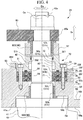
FIG. 4 is a sectional view showing a main portion of an inlet guide vane according to a first embodiment of this invention. -
FIG. 5 is an enlarged sectional view showing a portion inFIG. 5 . -
FIG. 6 is a sectional view showing a main portion of an inlet guide vane according to a second embodiment of this invention. -
FIG. 7 is a sectional view showing a main portion of an inlet guide vane according to a third embodiment of this invention. - Hereinafter, an inlet guide vane and a compressor according to the present invention will be described with reference to the drawings. As shown in
FIG. 1 , a centrifugal compressor system 1 includes adrive source 19 for generating power, adrive shaft 2, a drivenshaft 3, acompression unit 4, and aspeed increaser 10. - The
drive shaft 2 is driven to be rotatable around a central axis thereof by thedrive source 19. For example, as thedrive source 19, a steam turbine or a motor can be used. - The driven
shaft 3 is driven to be rotatable around the central axis by the power transmitted from thespeed increaser 10. The drivenshafts 3 are respectively located on both sides across thedrive shaft 2. The drivenshaft 3 has a first drivenshaft 5 and a second drivenshaft 6 which respectively extend parallel to thedrive shaft 2. - The
speed increaser 10 increases rotation speed of thedrive shaft 2, and transmits the rotation speed to the first drivenshaft 5 and the second drivenshaft 6. Inside acasing 20, thespeed increaser 10 includes adrive gear 11, a first drivengear 12, a second drivengear 13, a firstintermediate gear 14, and a secondintermediate gear 15. - The
drive gear 11 is disposed in a tip portion of thedrive shaft 2 inserted into thecasing 20 after penetrating thecasing 20, and is rotated integrally with thedrive shaft 2. Here, thedrive shaft 2 is supported by thecasing 20 via a bearing (not shown). - The first driven
gear 12 is disposed integrally with the first drivenshaft 5 in the intermediate portion in the direction of the central axis of the first drivenshaft 5. The second drivengear 13 is disposed integrally with the second drivenshaft 6 in the intermediate portion in the direction of the central axis of the second drivenshaft 6. The first drivenshaft 5 and the second drivenshaft 6 are supported by thecasing 20 via a bearing (not shown). The first drivengear 12 and the second drivengear 13 are located on both sides across thedrive gear 11 at an interval therebetween. - The first
intermediate gear 14 is located between thedrive gear 11 and the first drivengear 12, and meshes with thedrive gear 11 and the first drivengear 12. The secondintermediate gear 15 is located between thedrive gear 11 and the second drivengear 13 and meshes with thedrive gear 11 and the second drivengear 13. The firstintermediate gear 14 and the secondintermediate gear 15 are so-called idle gears. The firstintermediate gear 14 is disposed integrally with a firstintermediate shaft 17 rotatably supported by thecasing 20 via a bearing (not shown). The secondintermediate gear 15 is disposed integrally with a secondintermediate shaft 18 rotatably supported by thecasing 20 via a bearing (not shown). - In the
speed increaser 10 configured in this way, if thedrive shaft 2 is rotated by a drive force of thedrive source 19, thedrive gear 11 is rotated integrally with thedrive shaft 2. The rotation of thedrive gear 11 is transmitted to the first drivengear 12 and the second drivengear 13 via the firstintermediate gear 14 and the secondintermediate gear 15. In this manner, the first drivengear 12 and the second drivengear 13 are rotated. In conjunction with the rotation of the first drivengear 12, the first drivenshaft 5 is rotated. In conjunction with the rotation of the second drivengear 13, the second drivenshaft 6 is rotated. That is, since thedrive shaft 2 is driven, the first drivenshaft 5 and the second drivenshaft 6 are rotated. - The
compression unit 4 is driven by power transmitted from thedrive shaft 2 to the drivenshaft 3 via thespeed increaser 10. Thecompression unit 4 includes two first stage compression units (compressors) 7a and 7b, a second stage compression unit 8, and a third stage compression unit 9. - The first
stage compression units stage compression units shaft 5. The two firststage compression units stage compression units gas inlet 23, aninlet guide vane 24, and animpeller 25. - The
gas inlet 23 has a continuous cylindrical shape. Thegas inlet 23 internally forms an inlet flow path which introduces the fluid G serving as a compression target from the outside. - The
impeller 25 is attached to the first drivenshaft 5, and compresses the fluid G supplied from thegas inlet 23. - The
inlet guide vane 24 is disposed in thegas inlet 23. Theinlet guide vane 24 controls a flow rate of the fluid G passing through thegas inlet 23. - The second stage compression unit 8 is disposed in end portion on a side opposite to a side where the
drive source 19 is disposed in the second drivenshaft 6. The second stage compression unit 8 has an impeller 37 for compressing the fluid G. - The third stage compression unit 9 is disposed on a side which is the same as the side where the
drive source 19 is disposed in the second drivenshaft 6. The third stage compression unit 9 has an impeller 38 for compressing the fluid G. - Next, a connection configuration between the compression units will be described.
- The two first
stage compression units first stage pipe 30. Thefirst stage pipe 30 is configured to include two first stage compressionunit discharge pipes unit suction pipe 32. - A first
stage heat exchanger 27 is interposed between the first stage compressionunit discharge pipes unit suction pipe 32. The firststage heat exchanger 27 includes twoinlet nozzles 27a and oneoutlet nozzle 27b. The first stage compressionunit discharge pipes inlet nozzles 27a. The second stage compressionunit suction pipe 32 is connected to theoutlet nozzle 27b. That is, the firststage heat exchanger 27 has a function to cool the double system fluid G discharged from the two firststage compression units stage compression units stage heat exchanger 27 during a compression process. Accordingly, power needed to drive the centrifugal compressor system 1 is reduced. - The second stage compression unit 8 is connected to the third stage compression unit 9 via the
second stage pipe 33. Thesecond stage pipe 33 is configured to include a second stage compressionunit discharge pipe 34 and a third stage compressionunit suction pipe 35. - A second
stage heat exchanger 28 for cooling the fluid G discharged from the second stage compression unit 8 is disposed between the second stage compressionunit discharge pipe 34 and the third stage compressionunit suction pipe 35. The fluid G is intermediately cooled by the secondstage heat exchanger 28 during the compression process. Accordingly, the power needed to drive the centrifugal compressor system 1 is reduced. - The third stage compression
unit discharge pipe 36 is connected to the impeller 38 of the third stage compression unit 9. The third stage compressionunit discharge pipe 36 is connected to a predetermined plant P serving as a supply destination of the fluid G. - In the centrifugal compressor system 1 as described above, the fluid G to be compressed is introduced from the two
gas inlets stage compression units stage compression units - The fluid G compressed in the first
stage compression units unit discharge pipes stage heat exchanger 27. The merged fluid G is introduced to the second stage compression unit 8 through the second stage compressionunit suction pipe 32 after the being intermediately cooled by the firststage heat exchanger 27. - The fluid G is compressed in the second stage compression unit 8. Thereafter, the fluid G is fed to the second
stage heat exchanger 28 through the second stage compressionunit discharge pipe 34. In the secondstage heat exchanger 28, the fed fluid G is intermediately cooled. The intermediately cooled fluid G is introduced into the third stage compression unit 9 through the third stage compressionunit suction pipe 35. - After being compressed in the third stage compression unit 9, the fluid G is supplied to the predetermined plant P serving as a demand destination of the compressed fluid G through the third stage compression
unit discharge pipe 36. - Next, the
inlet guide vane 24 will be described in detail. - As shown in
FIGS. 2 to 4 , theinlet guide vane 24 includes aframe 50, a plurality ofmovable vanes 40, a bearingportion 60, and aseal portion 70. - As shown in
FIG. 2 , theframe 50 is a vane case having a cylindrical shape.
Theframe 50 is connected to a cylindrical body configuring the gas inlet 23 (refer toFIG. 1 ). In this manner, a portion of aflow path 100 of the fluid G flowing inside thegas inlet 23 is formed. An outer peripheral portion of theframe 50 has avane holder 51. A plurality ofinsertion holes 51h penetrating theframe 50 in a radial direction Dr are formed in thevane holder 51. The insertion holes 51h are formed at an interval in the circumferential direction. Themovable vane 40 can be attached to theinsertion hole 51h. Specifically, a shaft portion 42 (to be described later) of themovable vane 40 can be inserted into theinsertion hole 51h. - The
movable vane 40 is rotatably disposed with respect to theframe 50. The plurality ofmovable vanes 40 are disposed at an interval in the circumferential direction. Each of themovable vanes 40 has a vanemain body 41 and theshaft portion 42. - The vane
main body 41 is disposed on the inner side (first side) in the radial direction Dr with respect to theframe 50. The vanemain body 41 is located by aligning a vane length direction thereof with the radial direction Dr of theframe 50. In a state where theend portion 41b located on the inner side in the radial direction Dr leaves a clearance form acenter hub 44 disposed in a central portion of theframe 50, the vanemain body 41 is rotatable around a central axis Cs of theshaft portion 42. - The
shaft portion 42 is disposed integrally with theend portion 41a in the vane length direction which is located on the outer side (second side) in the radial direction Dr with respect to the vanemain body 41. Theshaft portion 42 has a substantially cylindrical shape extending along the direction of the extending central axis Cs of the central axis Cs. In the present embodiment, the direction of the central axis Cs is the radial direction Dr, and is also the vane length direction. In a rotatable state, theshaft portion 42 is inserted into theinsertion hole 51h formed in theframe 50. - As shown in
FIG. 3 , a tip portion 42s of theshaft portion 42 protrudes outward in the radial direction Dr from thevane holder 51. Anend portion 65a of alink plate 65 is fixed to the tip portion 42s of theshaft portion 42 so that theend portion 65a is not rotatable around the central axis Cs. Adrive pin 66 is connected to anend portion 65b of thelink plate 65. Thedrive pin 66 is disposed on the outer side in the radial direction Dr of theframe 50, and is supported so as to be rotatable around the central axis of thedrive pin 66 by a turningring 67 disposed so as to be capable of turning in the circumferential direction of theframe 50. The turningring 67 is rotatable around a central axis Cf (refer toFIG. 2 ) of theframe 50 by an actuator 26 (refer toFIG. 1 ). If the turningring 67 is turned around the central axis Cf by theactuator 26, thelink plate 65 oscillates around theshaft portion 42 as a center. In this manner, theshaft portion 42 is rotated around the central axis Cs. In this manner, an angle (opening degree) of the vanemain body 41 is changed in the flow of the fluid G in theflow path 100 inside theframe 50, and a flow rate of the fluid G passing through thegas inlet 23 is controlled. - As shown in
FIG. 4 , the bearingportion 60 is disposed inside theinsertion hole 51h in order to support each of themovable vanes 40. The bearingportion 60 supports theshaft portion 42 so as to be rotatable around the central axis Cs with respect to theinsertion hole 51h formed in theframe 50. The plurality of bearingportions 60 according to the present embodiment are disposed at an interval in the direction of the central axis Cs of theshaft portion 42. The bearingportion 60 has a cylindrical shape. According to the present embodiment, as the bearingportion 60, two of afirst bearing portion 60A and asecond bearing portion 60B are disposed therein. - The
vane holder 51 supporting theshaft portion 42 so as to be rotatable around the central axis Cs includes abase portion 52, a plurality ofseal holding members 55, anintermediate member 56, and aseal pressure member 57. - The
base portion 52 is formed so as to protrude outward in the radial direction Dr from an outerperipheral surface 50f of theframe 50. Thebase portion 52 has an outer peripheral recess portion (recess portion) 53 recessed inward in the radial direction Dr on an outerperipheral surface 52f of thebase portion 52 facing outward in the radial direction Dr of theframe 50. In addition, in theframe 50, a portion where thebase portion 52 is formed has an innerperipheral recess portion 54 recessed outward in the radial direction Dr of theframe 50 from an innerperipheral surface 50g thereof The innerperipheral recess portion 54 accommodates a portion of theend portion 41a of the vanemain body 41 of themovable vane 40. - In addition, the
base portion 52 has a base portion through-hole 52h extending along the radial direction Dr of theframe 50. The base portion through-hole 52h penetrates abottom surface 54b of an innerperipheral recess portion 54 and abottom surface 53b of an outerperipheral recess portion 53. The base portion through-hole 52h forms a portion of theinsertion hole 51h. Thefirst bearing portion 60A is fitted inward toward the outside in the radial direction Dr of theframe 50 with respect to the base portion through-hole 52h. - According to the present embodiment, two
seal holding members 55 are provided. Theseal holding members 55 are accommodated inside the outerperipheral recess portion 53 of thebase portion 52 in a stacked state along the direction of the central axis Cs. As shown inFIG. 5 , theseal holding member 55 has a holding member through-hole 55h forming a portion of theinsertion hole 51h in the central portion in the direction of the central axis Cs. In addition, theseal holding member 55 has anaccommodation portion 58 which accommodates a first seal member 71 (to be described later). - The
accommodation portion 58 is formed on a holding memberfirst surface 55f side in the direction of the central axis Cs of theseal holding member 55. Theaccommodation portion 58 has an annular shape continuous in the circumferential direction on the outer side in a hole diameter direction Ds of the holding member through-hole 55h, and is formed to be recessed toward the holding membersecond surface 55g side in the direction of the central axis Cs. Here, the holding memberfirst surface 55f is a surface facing outward in the radial direction Dr in theseal holding member 55. In addition, the holding membersecond surface 55g is a surface facing inward in the radial direction Dr in theseal holding member 55. Theaccommodation portion 58 has an inner peripheral side steppedportion 58a facing the inner peripheral side of the holding member through-hole 55h and an outer peripheral side stepped portion 58b which is recessed toward the holding membersecond surface 55g side and whose dimension is smaller than the inner peripheral side steppedportion 58a. The outer peripheral side stepped portion 58b is formed to be continuous with the outer peripheral side of the inner peripheral side steppedportion 58a. - In addition, on the holding member
second surface 55g side, theseal holding member 55 has a holdingmember groove 59 which is continuous in the circumferential direction and which is recessed toward the holding memberfirst surface 55f side. The holdingmember groove 59 is annularly formed on the outer side in the hole diameter direction Ds from theaccommodation portion 58 when viewed in the direction of the central axis Cs. The holdingmember groove 59 accommodates a third seal member 79 (to be described later). - On the intermediate member
second surface 56b side in the direction of the central axis Cs, theintermediate member 56 integrally has aflange portion 56d extending toward the outer peripheral side. In theintermediate member 56, theflange portion 56d is inserted into the outerperipheral recess portion 53 of thebase portion 52. Theintermediate member 56 is stacked on the outer side in the radial direction Dr with respect to theseal holding member 55. Outer peripheral portions of the twoseal holding members 55 and theintermediate member 56 are fastened and fixed to each other in thebase portion 52 by using abolt 61. - Here, the intermediate member
first surface 56a is a surface facing outward in the radial direction Dr in theintermediate member 56. In addition, the intermediate membersecond surface 56b is a surface facing inward in the radial direction Dr in theintermediate member 56. - On the intermediate member
first surface 56a side in the direction of the central axis Cs, theintermediate member 56 has anintermediate recess portion 561 recessed toward the intermediate membersecond surface 56b in the direction of the central axis Cs. In addition, theintermediate member 56 has an intermediate member through-hole 56h penetrating theintermediate recess portion 561 and the intermediate membersecond surface 56b in the central portion in the hole diameter direction Ds. The intermediate member through-hole 56h forms a portion of theinsertion hole 51h. - The
intermediate member 56 has a holeside recess portion 562 recessed outward in the hole diameter direction Ds of the intermediate member through-hole 56h. The holeside recess portion 562 is continuous in the circumferential direction around the central axis Cs in the intermediate portion in the direction of the central axis Cs of the intermediate member through-hole 56h. - The hole
side recess portion 562 may not be formed in theintermediate member 56, and a shaft side recess portion recessed inward in the hole diameter direction Ds may be formed on the outer peripheral surface 42f of theshaft portion 42. Therefore, at least one of the holeside recess portion 562 and the shaft side recess portion may be formed so as to form a space for widening a space between thefirst seal member 71 and thesecond seal member 72. - In addition, on the intermediate member
second surface 56b side, theintermediate member 56 has anintermediate member groove 563 which is continuous in the circumferential direction and which is recessed toward the intermediate memberfirst surface 56a side. Theintermediate member groove 563 is annularly formed on the outer side in the hole diameter direction Ds from theaccommodation portion 58 formed in theseal holding member 55 when viewed in the direction of the central axis Cs. Theintermediate member groove 563 accommodates a third seal member 79 (to be described later). - The
seal pressure member 57 is located on the outer side in the radial direction Dr with respect to theintermediate member 56. The central portion ofseal pressure member 57 has a through-hole 57h forming a portion of theinsertion hole 51h. Thesecond bearing portion 60B is fitted inward from the outer side in the radial direction Dr of theframe 50 with respect to theseal pressure member 57. On thesecond surface 57b side in the direction of the central axis Cs, theseal pressure member 57 has aninsertion cylinder portion 571 which is inserted into theintermediate recess portion 561 of theintermediate member 56. Thesecond seal member 72 located inside theintermediate recess portion 561 is interposed between theinsertion cylinder portion 571 of theseal pressure member 57 and thebottom surface 561b of theintermediate recess portion 561. - The
seal portion 70 is located inside theinsertion hole 51h of the above-describedvane holder 51. Theseal portion 70 is located between the plurality of bearingportions 60 in the direction of the central axis Cs. Theseal portion 70 seals a portion between theinsertion hole 51h and theshaft portion 42, thereby preventing the fluid G from flowing outward from the inner side of theframe 50, that is, flowing out of theflow path 100. Theseal portion 70 according to the present embodiment is disposed between thefirst bearing portion 60A and thesecond bearing portion 60B. Theseal portion 70 has thefirst seal member 71 and thesecond seal member 72 which are arranged at an interval in the direction of the central axis Cs. - The
first seal member 71 is accommodated in theaccommodation portion 58 of theseal holding member 55. Thefirst seal members 71 are respectively accommodated in the twoseal holding members 55. That is, thefirst seal members 71 are disposed in a double structure in the direction of the central axis Cs. - The
first seal member 71 has an annular seal portionmain body 73 to be accommodated in the inner peripheral side steppedportion 58a of theaccommodation portion 58 and alip portion 76 extending outward in the hole diameter direction Ds from the seal portionmain body 73. - The seal portion
main body 73 is continuous in the circumferential direction on the outer side in the hole diameter direction Ds of theshaft portion 42. The seal portionmain body 73 includes anelastic ring portion 74 and a biasingmember 75. Thelip portion 76 is accommodated in the outer peripheral side stepped portion 58b. - The
elastic ring portion 74 has an annular shape continuous in the circumferential direction on the outer side in the hole diameter direction Ds of theshaft portion 42. Theelastic ring portion 74 is made of an elastic material such as a rubber-based material. Theelastic ring portion 74 has aring groove 74m which is open inward in the radial direction Dr of theframe 50. - The biasing
member 75 is formed from a leaf spring material curved in an inverted U-shape which is open inward in the radial direction Dr.The biasing member 75 is accommodated inside thering groove 74m of theelastic ring portion 74. The biasingmember 75 causes the innerperipheral surface 74f of theelastic ring portion 74 to be biased inward in the hole diameter direction Ds of theinsertion hole 51h. - The
second seal member 72 is accommodated in theintermediate recess portion 561 of theintermediate member 56. Thesecond seal member 72 is located at a position farther from the vanemain body 41 than thefirst seal member 71. That is, the twofirst seal members 71 are arranged at a position closer to the vanemain body 41 than thesecond seal member 72 in theinsertion hole 51h. Thesecond seal member 72 includes aseal cap 77 and aseal ring 78. - The
seal cap 77 has acap groove 77m which has an annular shape and which is open outward in the hole diameter direction Ds of theinsertion hole 51h. Theseal ring 78 is made of a rubber-based material. Theseal ring 78 is disposed inside thecap groove 77m. Theseal ring 78 causes theseal cap 77 to be biased inward in the hole diameter direction Ds of theinsertion hole 51h. - In this way, the
first seal member 71 and thesecond seal member 72 have mutually different seal structures. In addition, thefirst seal member 71 located inward in the radial direction Dr from thesecond seal member 72 has sealing performance which is higher than that of thesecond seal member 72. - The
first seal member 71 and thesecond seal member 72 are not limited to an example where both of these have the mutually different seal structures. Both of these may have the same seal structure. - The
seal portion 70 further includes thethird seal member 79. Thethird seal member 79 is an O-ring made of an annular rubber-based material. Thethird seal members 79 are respectively accommodated in the holdingmember groove 59 and theintermediate member groove 563. Thethird seal member 79A accommodated in the holding member groove 59 seals a portion between theseal holding member 55A and thebottom surface 53b of the outerperipheral recess portion 53 of thebase portion 52 facing theseal holding member 55A. Thethird seal member 79C accommodated in the intermediate member groove 563 seals a portion between theintermediate member 56 and the seal holding member 55B. - In addition, the
seal portion 70 includes aseal space 80 between thefirst seal member 71 and thesecond seal member 72. Theseal space 80 is formed between thefirst seal member 71 and thesecond seal member 72. Theseal space 80 is formed so that a cross-sectional area of a clearance between theinsertion hole 51h and theshaft portion 42 is widened by the holeside recess portion 562. - According to the
inlet guide vane 24 and the centrifugal compressor system 1 of the above-described embodiment, theseal portion 70 located between the plurality offirst bearing portions 60A and thesecond bearing portion 60B prevent the fluid G inside theflow path 100 from leaking outward after passing between theinsertion hole 51h theshaft portion 42. Only the fluid passing through the clearance between thefirst bearing portion 60A and thesecond bearing portion 60B and the outer peripheral surface of theshaft portion 42 arrives at theseal portion 70. Therefore, theseal portion 70 is less likely to be exposed to the fluid, and is less likely to be affected by the fluid, compared to a case where theseal portion 70 is directly exposed to the fluid. Therefore, it is possible to continuously achieve the high sealing performance by preventing theseal portion 70 from being degraded. - In addition, the
first bearing portion 60A and thesecond bearing portion 60B which have the cylindrical shape are disposed on both sides in the direction of the central axis Cs of theshaft portion 42 with respect to theseal portion 70. Compared to a case of disposing a ball bearing, for example, instead of thefirst bearing portion 60A and thesecond bearing portion 60B, the clearance becomes smaller between the outer peripheral surface 42f of theshaft portion 42 and thefirst bearing portion 60A and thesecond bearing portion 60B. Therefore, only the fluid G passing through the clearance between thefirst bearing portion 60A and the outer peripheral surface 42f of theshaft portion 42 arrives at thefirst seal member 71. Accordingly, it is possible to effectively achieve the sealing performance in thefirst seal member 71. In this way, it is possible to improve the sealing performance in theshaft portion 42 of themovable vane 40. - In addition, the sealing performance can be improved by allowing the
seal portion 70 to have a double configuration of thefirst seal member 71 and thesecond seal member 72. Furthermore, thefirst seal members 71 are disposed in a double structure. Therefore, the sealing performance can be further improved. - In addition, the
first seal member 71 and thesecond seal member 72 are caused to have the mutually different seal structures, thereby configuring theseal portion 70 having a plurality of sealing characteristics. As a result, the higher sealing performance is ensured. - In addition, the
first seal member 71 has the sealing performance higher than that of thesecond seal member 72 located outward in the radial direction Dr which is away from the vanemain body 41 with respect to thefirst seal member 71. According to this configuration, thefirst seal member 71 can effectively prevent the fluid G from leaking out of theflow path 100 side. In addition, thesecond seal member 72 can function as a backup member for sealing the clearance against only the fluid G passing through thefirst seal member 71. Therefore, even if the sealing performance of thesecond seal member 72 is suppressed, the sealing performance of theseal portion 70 can be ensured as a whole. As a result, cost for thesecond seal member 72 can be minimized. - In addition, in the
first seal member 71, the biasingmember 75 causes the innerperipheral surface 74f of theelastic ring portion 74 to be biased inward in the hole diameter direction Ds. In this manner, it is possible to improve the sealing performance between thefirst seal member 71 and theshaft portion 42. - In addition, the
ring groove 74m of theelastic ring portion 74 is open inward in the radial direction Dr on theflow path 100 side of the fluid G. Accordingly, when the fluid G leaks out of theflow path 100 side, the fluid G flows into thering groove 74m. Since the fluid G flows into thering groove 74m, the innerperipheral surface 74f of theelastic ring portion 74 is pressed inward in the hole diameter direction Ds. Therefore, it is possible to improve the sealing performance between thefirst seal member 71 and theshaft portion 42. - In addition, the
frame 50 includes the plurality ofseal holding members 55 stacked along the direction of the central axis Cs. Thefirst seal member 71 can be accommodated in theaccommodation portion 58 from the holding memberfirst surface 55f side of the respectiveseal holding members 55. In this manner, assembling work can be more easily carried out, compared to a case where thefirst seal member 71 is assembled outward from the inside in the hole diameter direction Ds of the holding member through-hole 55h. - In addition, in the
first seal member 71, thelip portion 76 extending outward in the hole diameter direction Ds from the seal portionmain body 73 is interposed between theseal holding member 55 having thefirst seal member 71 incorporated therein and other members. Accordingly, thefirst seal member 71 is prevented from interfering with theshaft portion 42. In addition, the fluid G is prevented from leaking out of the clearance between theseal holding member 55 and other members. - In addition, the
third seal member 79 located on the outer side in the hole diameter direction Ds of thefirst seal member 71 can more reliably prevent the fluid G from leaking out of the clearance between the plurality of stackedseal holding members 55 and other members. - In addition, the
seal space 80 is formed between thefirst seal member 71 and thesecond seal member 72 by the holeside recess portion 562. When the fluid G leaks out of theflow path 100 side, the fluid G flows into theseal space 80. In this manner, the fluid G can be prevented from leaking outward. - Next, referring to
FIG. 6 , an inlet guide vane according to a second embodiment will be described. In the second embodiment, the same reference numerals will be given to the configuration elements which are the same as those according to the first embodiment, and detailed description thereof will be omitted. The inlet guide vane according to the second embodiment is different from that according to the first embodiment in that the inlet guide vane has a different configuration of the seal portion. - That is, as shown in
FIG. 6 , similar to theinlet guide vane 24 according to the first embodiment, aninlet guide vane 24B according to the second embodiment includes theframe 50 and the plurality ofmovable vanes 40. - The outer peripheral portion of the
frame 50 has thevane holder 51. Thevane holder 51 has theinsertion holes 51h formed so as to extend along the radial direction Dr of theframe 50 at a plurality of locations formed at an interval in the circumferential direction. - The
movable vane 40 is supported by thefirst bearing portion 60A and thesecond bearing portion 60B which are disposed in theinsertion hole 51h so that theshaft portion 42 is rotatable around the central axis Cs. - A
seal portion 70B is disposed between thefirst bearing portion 60A and thesecond bearing portion 60B. Aseal space 80B is formed between thefirst seal member 71 and thesecond seal member 72 of theseal portion 70B by a holeside recess portion 562 formed in theintermediate member 56. - The
seal portion 70B includes asensor 90 which detects that the fluid G inside theflow path 100 enters theseal space 80B. Thesensor 90 detects that the fluid G enters theseal space 80B by detecting the pressure, the temperature, or the substances configuring the fluid G inside theseal space 80B. - According to the configuration as described above, similar to the first embodiment, the sealing performance in the
shaft portion 42 of themovable vane 40 can be improved. Furthermore, thesensor 90 can detect that the fluid G leaks to the clearance between theinsertion hole 51h and theshaft portion 42 from the inside of theflow path 100. In this manner, in a case where thesensor 90 detects the leakage of the fluid G, maintenance work for theseal portion 70B can be carried out at a proper timing by stopping the operation of the centrifugal compressor system 1. - Next, referring to
FIG. 7 , an inlet guide vane according to a third embodiment will be described. In the third embodiment, the same reference numerals will be given to the configuration elements which are the same as those according to the first and second embodiments, and detailed description thereof will be omitted. The inlet guide vane according to the third embodiment is different from those according to the first and second embodiments in that the inlet guide vane has a different configuration of the seal portion. - That is, as shown in
FIG. 7 , similar to theinlet guide vane 24 according to the first embodiment, aninlet guide vane 24C according to the third embodiment includes theframe 50 and the plurality ofmovable vanes 40. - The outer peripheral portion of the
frame 50 has thevane holder 51. Thevane holder 51 has theinsertion holes 51h formed so as to extend along the radial direction Dr of theframe 50 at a plurality of locations formed at an interval in the circumferential direction. - The
movable vane 40 is supported by thefirst bearing portion 60A and thesecond bearing portion 60B which are disposed in theinsertion hole 51h so that theshaft portion 42 is rotatable around the central axis Cs. - A
seal portion 70C is disposed between thefirst bearing portion 60A and thesecond bearing portion 60B. Aseal space 80C is formed between thefirst seal member 71 and thesecond seal member 72 of theseal portion 70C by the holeside recess portion 562 formed in theintermediate member 56. - The
intermediate member 56 has acommunication hole 568 which allows the outside and the holeside recess portion 562 to communicate with each other. A sealingfluid supply unit 95 is connected to thecommunication hole 568. The sealingfluid supply unit 95 supplies a sealing fluid Gs from the outside to theseal space 80C of the clearance between theinsertion hole 51h and theshaft portion 42. - The sealing
fluid supply unit 95 pressurizes theseal space 80C by supplying the sealing fluid Gs. It is preferable that the pressure inside thepressurized seal space 80C is lower than the pressure inside theflow path 100 and higher than the pressure (atmospheric pressure) outside theframe 50. - According to the configuration as described above, similar to the above-described first embodiment, the sealing performance in the
shaft portion 42 of themovable vane 40 can be improved. Furthermore, the sealing fluid Gs is fed from the outside into theseal space 80C between thefirst seal member 71 and thesecond seal member 72 so as to pressurize the inside of theseal space 80C. In this manner, a pressure difference decreases between the pressure of the fluid G inside theflow path 100 and the pressure inside theseal space 80C. As a result, it is possible to prevent the fluid G inside theflow path 100 from flowing into the portion between thefirst seal member 71 and thesecond seal member 72. Accordingly, the sealing performance can be further improved. In this manner, it is possible to prevent thefirst seal member 71 from being damaged. - Hitherto, the embodiments according to the present invention have been described in detail with reference to the drawings. However, the respective configurations and combinations thereof in the respective embodiments are merely examples. The present invention is not limited by the embodiments, and is limited only by the appended claims.
- For example, the
inlet guide vanes - According to the inlet guide vane and the compressor which are described above, it is possible to improve the sealing performance in the shaft portion of the movable vane of the inlet guide vane.
-
- 1: centrifugal compressor system
- 2: drive shaft
- 3: driven shaft
- 4: compression unit
- 5: first driven shaft
- 6: second driven shaft
- 7a, 7b: first stage compression unit (compressor)
- 8: second stage compression unit
- 9: third stage compression unit
- 10: speed increaser
- 11: drive gear
- 12: first driven gear
- 13: second driven gear
- 14: first intermediate gear
- 15: second intermediate gear
- 17: first intermediate shaft
- 18: second intermediate shaft
- 19: drive source
- 20: casing
- 23: gas inlet
- 24, 24B, 24C: inlet guide vane
- 25, 37, 38: impeller
- 26: actuator
- 27: first stage heat exchanger
- 27a: inlet nozzle
- 27b: outlet nozzle
- 28: second stage heat exchanger
- 30: first stage pipe
- 31a, 31b: first stage compression unit discharge pipe
- 32: second stage compression unit suction pipe
- 33: second stage pipe
- 34: second stage compression unit discharge pipe
- 35: third stage compression unit suction pipe
- 36: third stage compression unit discharge pipe
- 40: movable vane
- 41: vane main body
- 41a, 41b: end portion
- 42: shaft portion
- 42f: outer peripheral surface
- 42s: tip portion
- 44: center hub
- 50: frame
- 50f: outer peripheral surface
- 50g: inner peripheral surface
- 51: vane holder
- 51f: inner peripheral surface
- 51h: insertion hole
- 52: base portion
- 52f: outer peripheral surface
- 52h: base portion through-hole
- 53: outer peripheral recess portion
- 53b: bottom surface
- 54: inner peripheral recess portion
- 54b: bottom surface
- 55, 55A, 55B: seal holding member
- 55f: holding member first surface
- 55g: holding member second surface
- 55h: holding member through-hole
- 56: intermediate member
- 56a: intermediate member first surface
- 56b: intermediate member second surface
- 56d: flange portion
- 56h: intermediate member through-hole
- 561: intermediate recess portion
- 561b: bottom surface
- 562: hole side recess portion
- 563: intermediate member groove
- 568: communication hole
- 57: seal pressure member
- 57b: second surface
- 57h: through-hole
- 571: insertion cylinder portion
- 58: accommodation portion
- 58a: inner peripheral side stepped portion
- 58b: outer peripheral side stepped portion
- 59: holding member groove
- 60: bearing portion
- 60A: first bearing portion
- 60B: second bearing portion
- 61: bolt
- 65: link plate
- 65a, 65b: end portion
- 66: drive pin
- 67: turning ring
- 70, 70B, 70C: seal portion
- 71: first seal member
- 72: second seal member
- 73: seal portion main body
- 74: elastic ring portion
- 74f: inner peripheral surface
- 74m: ring groove
- 75: biasing member
- 76: lip portion
- 77: seal cap
- 77m: cap groove
- 78: seal ring
- 79, 79A, 79B, 79C: third seal member
- 80, 80B, 80C: seal space
- 90: sensor
- 95: sealing fluid supply unit
- 100: flow path
- Cs: central axis
- Dr: radial direction
- Ds: hole diameter direction
- G: fluid
- Gs: sealing fluid
- P: plant
Claims (8)
- An inlet guide vane (24) comprising:a movable vane (40) that has a vane main body (41) and a shaft portion (42) disposed in an end portion of the vane main body (41);a frame (50) that has an insertion hole (51h) into which the shaft portion (42) is to be inserted;a plurality of bearing portions (60) that are arranged inside the insertion hole (51h) at an interval in a direction of a central axis (Cs) of the shaft portion (42), and that support the shaft portion (42) so as to be rotatable around the central axis (Cs) with respect to the frame (50); anda seal portion (70) that is located inside the insertion hole (51h) between the plurality of bearing portions (60) in the direction of the central axis (Cs), and that is configured to seal between the insertion hole (51h) and the shaft portion (42), wherein the shaft portion (42) is disposed integrally with a radially outer end portion (41a) of the vane main body (41), characterized in thatthe seal portion (70) includes a first seal member (71) and a second seal member (72) which are located at an interval in the direction of the central axis (Cs).
- The inlet guide vane according to Claim 1,
wherein the first seal member (71) and the second seal member (72) have seal structures which are different from each other. - The inlet guide vane according to Claim 2,
wherein the first seal member (71) is located at a position closer to the vane main body (41) than the second seal member (72), and has a sealing performance higher than that
of the second seal member. - The inlet guide vane according to any one of Claims 1 to 3,
wherein at least any one of a hole side recess portion formed on an inner peripheral surface of the insertion hole (51h) and recessed outward in a radial direction and a shaft side recess portion formed on an outer peripheral surface of the shaft portion and recessed inward in the radial direction is formed between the first seal member (71) and the second seal member (72). - The inlet guide vane according to any one of Claims 1 to 4, further comprising:
a sensor (90) that is disposed between the first seal member (71) and the second seal member (72), and that is configured to detect a fluid entering a clearance between an inner peripheral surface of the insertion hole and an outer peripheral surface of the shaft portion. - The inlet guide vane according to any one of Claims 1 to 5, further comprising:
a sealing fluid supply unit (95) that is disposed between the first seal member (71) and the second seal member (72), and that is configured to supply a sealing fluid from the outside to a clearance between an inner peripheral surface of the insertion hole and an outer peripheral surface of the shaft portion. - The inlet guide vane according to any one of Claims 1 to 6,
wherein the seal portion (70) includes
an elastic ring portion (74) which is disposed outward in a radial direction of the shaft portion (42), which has an annular shape continuous in a circumferential direction, and which has a groove (74m) open toward a side where the vane main body (41) is located with respect to the frame (50), and
a biasing member (75) which is disposed in the groove (74m), and which is configured to cause an inner peripheral surface of the elastic ring portion (74) to be biased inward in the radial direction toward the shaft portion (42). - A compressor comprising:
the inlet guide vane according to any one of Claims 1 to 7.
Applications Claiming Priority (1)
| Application Number | Priority Date | Filing Date | Title |
|---|---|---|---|
| PCT/JP2017/004184 WO2018142606A1 (en) | 2017-02-06 | 2017-02-06 | Inlet guide vane and compressor |
Publications (3)
| Publication Number | Publication Date |
|---|---|
| EP3550154A1 EP3550154A1 (en) | 2019-10-09 |
| EP3550154A4 EP3550154A4 (en) | 2019-12-18 |
| EP3550154B1 true EP3550154B1 (en) | 2021-01-06 |
Family
ID=63041196
Family Applications (1)
| Application Number | Title | Priority Date | Filing Date |
|---|---|---|---|
| EP17894791.7A Active EP3550154B1 (en) | 2017-02-06 | 2017-02-06 | Inlet guide vane and compressor |
Country Status (4)
| Country | Link |
|---|---|
| US (1) | US11041401B2 (en) |
| EP (1) | EP3550154B1 (en) |
| JP (1) | JP6810168B2 (en) |
| WO (1) | WO2018142606A1 (en) |
Families Citing this family (6)
| Publication number | Priority date | Publication date | Assignee | Title |
|---|---|---|---|---|
| CN110374891B (en) * | 2019-08-19 | 2021-03-23 | 重庆美的通用制冷设备有限公司 | Centrifugal compressor |
| CN111664110B (en) * | 2020-05-25 | 2021-09-07 | 中国科学院工程热物理研究所 | A kind of compressor inlet guide vane adjustment mechanism and control method thereof |
| JP7531380B2 (en) | 2020-12-14 | 2024-08-09 | 三菱重工コンプレッサ株式会社 | Rotating Machinery |
| CN114483629B (en) * | 2022-01-13 | 2023-07-28 | 江苏海拓宾未来工业科技集团有限公司 | Multi-shaft multi-stage hydrogen fuel high-speed centrifugal compressor |
| CN115479048B (en) * | 2022-10-11 | 2024-08-09 | 中国航发湖南动力机械研究所 | Rotatable guide vane journal structure and compressor |
| US20260009338A1 (en) * | 2024-07-02 | 2026-01-08 | Pratt & Whitney Canada Corp. | Variable inlet guide vane with angled vane inlet and conforming shroud plug |
Family Cites Families (12)
| Publication number | Priority date | Publication date | Assignee | Title |
|---|---|---|---|---|
| JPS61215499A (en) | 1985-03-22 | 1986-09-25 | Ebara Corp | Capacity control device for centrifugal compressor |
| US5622473A (en) * | 1995-11-17 | 1997-04-22 | General Electric Company | Variable stator vane assembly |
| US6210106B1 (en) * | 1999-04-30 | 2001-04-03 | General Electric Company | Seal apparatus for gas turbine engine variable vane |
| US6767183B2 (en) * | 2002-09-18 | 2004-07-27 | General Electric Company | Methods and apparatus for sealing gas turbine engine variable vane assemblies |
| US7207770B2 (en) * | 2003-05-27 | 2007-04-24 | General Electric Company | Variable stator vane bushings and washers |
| US7445427B2 (en) | 2005-12-05 | 2008-11-04 | General Electric Company | Variable stator vane assembly and bushing thereof |
| FR2902822B1 (en) * | 2006-06-21 | 2008-08-22 | Snecma Sa | STATOR BEARING FOR STATOR WITH VARIABLE SHAFT |
| US9200640B2 (en) | 2009-11-03 | 2015-12-01 | Ingersoll-Rand Company | Inlet guide vane for a compressor |
| JP6185781B2 (en) | 2013-07-23 | 2017-08-23 | 三菱日立パワーシステムズ株式会社 | Axial flow compressor |
| EP3088775A4 (en) | 2013-12-10 | 2017-11-01 | NSK Ltd. | Seal mechanism, drive device for seal mechanism, transport device, and manufacturing device |
| JP6015715B2 (en) * | 2013-12-10 | 2016-10-26 | 日本精工株式会社 | SEALING MECHANISM, SEALING MECHANISM DRIVE DEVICE, CONVEYING DEVICE, AND MANUFACTURING DEVICE |
| US9903451B2 (en) | 2014-10-31 | 2018-02-27 | Trane International Inc. | Linkage to actuate inlet guide vanes |
-
2017
- 2017-02-06 WO PCT/JP2017/004184 patent/WO2018142606A1/en not_active Ceased
- 2017-02-06 EP EP17894791.7A patent/EP3550154B1/en active Active
- 2017-02-06 US US16/475,883 patent/US11041401B2/en active Active
- 2017-02-06 JP JP2018565218A patent/JP6810168B2/en active Active
Non-Patent Citations (1)
| Title |
|---|
| None * |
Also Published As
| Publication number | Publication date |
|---|---|
| US11041401B2 (en) | 2021-06-22 |
| EP3550154A4 (en) | 2019-12-18 |
| WO2018142606A1 (en) | 2018-08-09 |
| JPWO2018142606A1 (en) | 2019-11-07 |
| JP6810168B2 (en) | 2021-01-06 |
| US20190376409A1 (en) | 2019-12-12 |
| EP3550154A1 (en) | 2019-10-09 |
Similar Documents
| Publication | Publication Date | Title |
|---|---|---|
| EP3550154B1 (en) | Inlet guide vane and compressor | |
| EP2631489B1 (en) | Compressor | |
| JP5791779B2 (en) | gas turbine | |
| JP5769332B2 (en) | Scroll expander | |
| US11209009B2 (en) | Rotating machine | |
| EP3456980B1 (en) | Compressor | |
| KR20120115336A (en) | Abrasive Seal with Axial Offset | |
| EP1967774A1 (en) | Coaxial multi-shaft assemblies | |
| US20170130646A1 (en) | Variable nozzle unit and variable geometry system turbocharger | |
| JP2011069280A (en) | Sealing mechanism including multistage brush seal | |
| KR20070121584A (en) | Turbine and Annular Component Carrier Assemblies | |
| CN112154261B (en) | Bearing structure and supercharger | |
| EP2431574A1 (en) | Gas turbine and method for operating a gas turbine | |
| US20080217861A1 (en) | Coaxial Multi-Shaft Assemblies | |
| US10641278B2 (en) | Sealing device and rotating machine | |
| US11162381B2 (en) | Turbocharger | |
| JP6655712B2 (en) | Rotating machinery | |
| JP5071283B2 (en) | Turbocharger | |
| CN111936748B (en) | Fluid machine, in particular compressor device | |
| EP3879071B1 (en) | Turbine rotor | |
| US10227887B2 (en) | Fluid machine with variable vanes | |
| JP7774487B2 (en) | Tilting Pad Bearing | |
| US11572797B2 (en) | Turbine rotor and axial flow turbine | |
| JP2013194674A (en) | Turbine | |
| JP2009250151A (en) | Thrust reduction device of axial flow turbine |
Legal Events
| Date | Code | Title | Description |
|---|---|---|---|
| STAA | Information on the status of an ep patent application or granted ep patent |
Free format text: STATUS: THE INTERNATIONAL PUBLICATION HAS BEEN MADE |
|
| PUAI | Public reference made under article 153(3) epc to a published international application that has entered the european phase |
Free format text: ORIGINAL CODE: 0009012 |
|
| STAA | Information on the status of an ep patent application or granted ep patent |
Free format text: STATUS: REQUEST FOR EXAMINATION WAS MADE |
|
| 17P | Request for examination filed |
Effective date: 20190704 |
|
| AK | Designated contracting states |
Kind code of ref document: A1 Designated state(s): AL AT BE BG CH CY CZ DE DK EE ES FI FR GB GR HR HU IE IS IT LI LT LU LV MC MK MT NL NO PL PT RO RS SE SI SK SM TR |
|
| AX | Request for extension of the european patent |
Extension state: BA ME |
|
| A4 | Supplementary search report drawn up and despatched |
Effective date: 20191119 |
|
| RIC1 | Information provided on ipc code assigned before grant |
Ipc: F04D 29/08 20060101ALI20191113BHEP Ipc: F04D 29/56 20060101AFI20191113BHEP Ipc: F04D 25/16 20060101ALN20191113BHEP Ipc: F04D 29/46 20060101ALI20191113BHEP Ipc: F04D 29/057 20060101ALI20191113BHEP |
|
| DAV | Request for validation of the european patent (deleted) | ||
| DAX | Request for extension of the european patent (deleted) | ||
| GRAP | Despatch of communication of intention to grant a patent |
Free format text: ORIGINAL CODE: EPIDOSNIGR1 |
|
| STAA | Information on the status of an ep patent application or granted ep patent |
Free format text: STATUS: GRANT OF PATENT IS INTENDED |
|
| INTG | Intention to grant announced |
Effective date: 20200731 |
|
| RIC1 | Information provided on ipc code assigned before grant |
Ipc: F04D 29/08 20060101ALI20200720BHEP Ipc: F04D 29/56 20060101AFI20200720BHEP Ipc: F04D 29/057 20060101ALI20200720BHEP Ipc: F04D 29/46 20060101ALI20200720BHEP Ipc: F04D 25/16 20060101ALN20200720BHEP |
|
| RIN1 | Information on inventor provided before grant (corrected) |
Inventor name: ODA, TAKASHI |
|
| GRAS | Grant fee paid |
Free format text: ORIGINAL CODE: EPIDOSNIGR3 |
|
| GRAA | (expected) grant |
Free format text: ORIGINAL CODE: 0009210 |
|
| STAA | Information on the status of an ep patent application or granted ep patent |
Free format text: STATUS: THE PATENT HAS BEEN GRANTED |
|
| AK | Designated contracting states |
Kind code of ref document: B1 Designated state(s): AL AT BE BG CH CY CZ DE DK EE ES FI FR GB GR HR HU IE IS IT LI LT LU LV MC MK MT NL NO PL PT RO RS SE SI SK SM TR |
|
| REG | Reference to a national code |
Ref country code: GB Ref legal event code: FG4D |
|
| REG | Reference to a national code |
Ref country code: AT Ref legal event code: REF Ref document number: 1352672 Country of ref document: AT Kind code of ref document: T Effective date: 20210115 Ref country code: CH Ref legal event code: EP |
|
| REG | Reference to a national code |
Ref country code: DE Ref legal event code: R096 Ref document number: 602017031229 Country of ref document: DE |
|
| REG | Reference to a national code |
Ref country code: IE Ref legal event code: FG4D |
|
| REG | Reference to a national code |
Ref country code: NL Ref legal event code: MP Effective date: 20210106 |
|
| REG | Reference to a national code |
Ref country code: AT Ref legal event code: MK05 Ref document number: 1352672 Country of ref document: AT Kind code of ref document: T Effective date: 20210106 |
|
| REG | Reference to a national code |
Ref country code: LT Ref legal event code: MG9D |
|
| PG25 | Lapsed in a contracting state [announced via postgrant information from national office to epo] |
Ref country code: NO Free format text: LAPSE BECAUSE OF FAILURE TO SUBMIT A TRANSLATION OF THE DESCRIPTION OR TO PAY THE FEE WITHIN THE PRESCRIBED TIME-LIMIT Effective date: 20210406 Ref country code: PT Free format text: LAPSE BECAUSE OF FAILURE TO SUBMIT A TRANSLATION OF THE DESCRIPTION OR TO PAY THE FEE WITHIN THE PRESCRIBED TIME-LIMIT Effective date: 20210506 Ref country code: HR Free format text: LAPSE BECAUSE OF FAILURE TO SUBMIT A TRANSLATION OF THE DESCRIPTION OR TO PAY THE FEE WITHIN THE PRESCRIBED TIME-LIMIT Effective date: 20210106 Ref country code: FI Free format text: LAPSE BECAUSE OF FAILURE TO SUBMIT A TRANSLATION OF THE DESCRIPTION OR TO PAY THE FEE WITHIN THE PRESCRIBED TIME-LIMIT Effective date: 20210106 Ref country code: GR Free format text: LAPSE BECAUSE OF FAILURE TO SUBMIT A TRANSLATION OF THE DESCRIPTION OR TO PAY THE FEE WITHIN THE PRESCRIBED TIME-LIMIT Effective date: 20210407 Ref country code: BG Free format text: LAPSE BECAUSE OF FAILURE TO SUBMIT A TRANSLATION OF THE DESCRIPTION OR TO PAY THE FEE WITHIN THE PRESCRIBED TIME-LIMIT Effective date: 20210406 Ref country code: LT Free format text: LAPSE BECAUSE OF FAILURE TO SUBMIT A TRANSLATION OF THE DESCRIPTION OR TO PAY THE FEE WITHIN THE PRESCRIBED TIME-LIMIT Effective date: 20210106 |
|
| PG25 | Lapsed in a contracting state [announced via postgrant information from national office to epo] |
Ref country code: SE Free format text: LAPSE BECAUSE OF FAILURE TO SUBMIT A TRANSLATION OF THE DESCRIPTION OR TO PAY THE FEE WITHIN THE PRESCRIBED TIME-LIMIT Effective date: 20210106 Ref country code: LV Free format text: LAPSE BECAUSE OF FAILURE TO SUBMIT A TRANSLATION OF THE DESCRIPTION OR TO PAY THE FEE WITHIN THE PRESCRIBED TIME-LIMIT Effective date: 20210106 Ref country code: PL Free format text: LAPSE BECAUSE OF FAILURE TO SUBMIT A TRANSLATION OF THE DESCRIPTION OR TO PAY THE FEE WITHIN THE PRESCRIBED TIME-LIMIT Effective date: 20210106 Ref country code: RS Free format text: LAPSE BECAUSE OF FAILURE TO SUBMIT A TRANSLATION OF THE DESCRIPTION OR TO PAY THE FEE WITHIN THE PRESCRIBED TIME-LIMIT Effective date: 20210106 Ref country code: AT Free format text: LAPSE BECAUSE OF FAILURE TO SUBMIT A TRANSLATION OF THE DESCRIPTION OR TO PAY THE FEE WITHIN THE PRESCRIBED TIME-LIMIT Effective date: 20210106 |
|
| PG25 | Lapsed in a contracting state [announced via postgrant information from national office to epo] |
Ref country code: IS Free format text: LAPSE BECAUSE OF FAILURE TO SUBMIT A TRANSLATION OF THE DESCRIPTION OR TO PAY THE FEE WITHIN THE PRESCRIBED TIME-LIMIT Effective date: 20210506 |
|
| REG | Reference to a national code |
Ref country code: DE Ref legal event code: R097 Ref document number: 602017031229 Country of ref document: DE |
|
| REG | Reference to a national code |
Ref country code: BE Ref legal event code: MM Effective date: 20210228 |
|
| PG25 | Lapsed in a contracting state [announced via postgrant information from national office to epo] |
Ref country code: CZ Free format text: LAPSE BECAUSE OF FAILURE TO SUBMIT A TRANSLATION OF THE DESCRIPTION OR TO PAY THE FEE WITHIN THE PRESCRIBED TIME-LIMIT Effective date: 20210106 Ref country code: EE Free format text: LAPSE BECAUSE OF FAILURE TO SUBMIT A TRANSLATION OF THE DESCRIPTION OR TO PAY THE FEE WITHIN THE PRESCRIBED TIME-LIMIT Effective date: 20210106 Ref country code: LU Free format text: LAPSE BECAUSE OF NON-PAYMENT OF DUE FEES Effective date: 20210206 Ref country code: LI Free format text: LAPSE BECAUSE OF NON-PAYMENT OF DUE FEES Effective date: 20210228 Ref country code: MC Free format text: LAPSE BECAUSE OF FAILURE TO SUBMIT A TRANSLATION OF THE DESCRIPTION OR TO PAY THE FEE WITHIN THE PRESCRIBED TIME-LIMIT Effective date: 20210106 Ref country code: SM Free format text: LAPSE BECAUSE OF FAILURE TO SUBMIT A TRANSLATION OF THE DESCRIPTION OR TO PAY THE FEE WITHIN THE PRESCRIBED TIME-LIMIT Effective date: 20210106 Ref country code: CH Free format text: LAPSE BECAUSE OF NON-PAYMENT OF DUE FEES Effective date: 20210228 |
|
| PLBE | No opposition filed within time limit |
Free format text: ORIGINAL CODE: 0009261 |
|
| STAA | Information on the status of an ep patent application or granted ep patent |
Free format text: STATUS: NO OPPOSITION FILED WITHIN TIME LIMIT |
|
| PG25 | Lapsed in a contracting state [announced via postgrant information from national office to epo] |
Ref country code: RO Free format text: LAPSE BECAUSE OF FAILURE TO SUBMIT A TRANSLATION OF THE DESCRIPTION OR TO PAY THE FEE WITHIN THE PRESCRIBED TIME-LIMIT Effective date: 20210106 Ref country code: DK Free format text: LAPSE BECAUSE OF FAILURE TO SUBMIT A TRANSLATION OF THE DESCRIPTION OR TO PAY THE FEE WITHIN THE PRESCRIBED TIME-LIMIT Effective date: 20210106 Ref country code: SK Free format text: LAPSE BECAUSE OF FAILURE TO SUBMIT A TRANSLATION OF THE DESCRIPTION OR TO PAY THE FEE WITHIN THE PRESCRIBED TIME-LIMIT Effective date: 20210106 |
|
| 26N | No opposition filed |
Effective date: 20211007 |
|
| GBPC | Gb: european patent ceased through non-payment of renewal fee |
Effective date: 20210406 |
|
| PG25 | Lapsed in a contracting state [announced via postgrant information from national office to epo] |
Ref country code: AL Free format text: LAPSE BECAUSE OF FAILURE TO SUBMIT A TRANSLATION OF THE DESCRIPTION OR TO PAY THE FEE WITHIN THE PRESCRIBED TIME-LIMIT Effective date: 20210106 Ref country code: IE Free format text: LAPSE BECAUSE OF NON-PAYMENT OF DUE FEES Effective date: 20210206 Ref country code: FR Free format text: LAPSE BECAUSE OF NON-PAYMENT OF DUE FEES Effective date: 20210306 Ref country code: GB Free format text: LAPSE BECAUSE OF NON-PAYMENT OF DUE FEES Effective date: 20210406 Ref country code: ES Free format text: LAPSE BECAUSE OF FAILURE TO SUBMIT A TRANSLATION OF THE DESCRIPTION OR TO PAY THE FEE WITHIN THE PRESCRIBED TIME-LIMIT Effective date: 20210106 |
|
| PG25 | Lapsed in a contracting state [announced via postgrant information from national office to epo] |
Ref country code: SI Free format text: LAPSE BECAUSE OF FAILURE TO SUBMIT A TRANSLATION OF THE DESCRIPTION OR TO PAY THE FEE WITHIN THE PRESCRIBED TIME-LIMIT Effective date: 20210106 |
|
| PG25 | Lapsed in a contracting state [announced via postgrant information from national office to epo] |
Ref country code: IS Free format text: LAPSE BECAUSE OF FAILURE TO SUBMIT A TRANSLATION OF THE DESCRIPTION OR TO PAY THE FEE WITHIN THE PRESCRIBED TIME-LIMIT Effective date: 20210506 |
|
| PG25 | Lapsed in a contracting state [announced via postgrant information from national office to epo] |
Ref country code: BE Free format text: LAPSE BECAUSE OF NON-PAYMENT OF DUE FEES Effective date: 20210228 |
|
| PG25 | Lapsed in a contracting state [announced via postgrant information from national office to epo] |
Ref country code: NL Free format text: LAPSE BECAUSE OF NON-PAYMENT OF DUE FEES Effective date: 20210206 Ref country code: CY Free format text: LAPSE BECAUSE OF FAILURE TO SUBMIT A TRANSLATION OF THE DESCRIPTION OR TO PAY THE FEE WITHIN THE PRESCRIBED TIME-LIMIT Effective date: 20210106 |
|
| PG25 | Lapsed in a contracting state [announced via postgrant information from national office to epo] |
Ref country code: HU Free format text: LAPSE BECAUSE OF FAILURE TO SUBMIT A TRANSLATION OF THE DESCRIPTION OR TO PAY THE FEE WITHIN THE PRESCRIBED TIME-LIMIT; INVALID AB INITIO Effective date: 20170206 |
|
| PG25 | Lapsed in a contracting state [announced via postgrant information from national office to epo] |
Ref country code: MK Free format text: LAPSE BECAUSE OF FAILURE TO SUBMIT A TRANSLATION OF THE DESCRIPTION OR TO PAY THE FEE WITHIN THE PRESCRIBED TIME-LIMIT Effective date: 20210106 |
|
| PGFP | Annual fee paid to national office [announced via postgrant information from national office to epo] |
Ref country code: IT Payment date: 20240111 Year of fee payment: 8 |
|
| PG25 | Lapsed in a contracting state [announced via postgrant information from national office to epo] |
Ref country code: MT Free format text: LAPSE BECAUSE OF FAILURE TO SUBMIT A TRANSLATION OF THE DESCRIPTION OR TO PAY THE FEE WITHIN THE PRESCRIBED TIME-LIMIT Effective date: 20210106 |
|
| PGFP | Annual fee paid to national office [announced via postgrant information from national office to epo] |
Ref country code: DE Payment date: 20241231 Year of fee payment: 9 |
|
| PG25 | Lapsed in a contracting state [announced via postgrant information from national office to epo] |
Ref country code: TR Free format text: LAPSE BECAUSE OF FAILURE TO SUBMIT A TRANSLATION OF THE DESCRIPTION OR TO PAY THE FEE WITHIN THE PRESCRIBED TIME-LIMIT Effective date: 20210106 |
|
| PG25 | Lapsed in a contracting state [announced via postgrant information from national office to epo] |
Ref country code: IT Free format text: LAPSE BECAUSE OF NON-PAYMENT OF DUE FEES Effective date: 20250206 |