JP6809027B2 - Communication device and communication method - Google Patents
Communication device and communication method Download PDFInfo
- Publication number
- JP6809027B2 JP6809027B2 JP2016155673A JP2016155673A JP6809027B2 JP 6809027 B2 JP6809027 B2 JP 6809027B2 JP 2016155673 A JP2016155673 A JP 2016155673A JP 2016155673 A JP2016155673 A JP 2016155673A JP 6809027 B2 JP6809027 B2 JP 6809027B2
- Authority
- JP
- Japan
- Prior art keywords
- communication
- relay terminal
- base station
- terminal
- communication quality
- Prior art date
- Legal status (The legal status is an assumption and is not a legal conclusion. Google has not performed a legal analysis and makes no representation as to the accuracy of the status listed.)
- Active
Links
- 238000004891 communication Methods 0.000 title claims description 697
- 238000000034 method Methods 0.000 title claims description 75
- 238000005259 measurement Methods 0.000 claims description 75
- 230000006866 deterioration Effects 0.000 claims description 3
- 230000008859 change Effects 0.000 claims description 2
- 230000006872 improvement Effects 0.000 claims description 2
- 238000012545 processing Methods 0.000 description 64
- 238000010586 diagram Methods 0.000 description 38
- 230000006870 function Effects 0.000 description 30
- 230000008569 process Effects 0.000 description 20
- 230000011664 signaling Effects 0.000 description 17
- 230000007704 transition Effects 0.000 description 15
- 230000002093 peripheral effect Effects 0.000 description 10
- 238000011084 recovery Methods 0.000 description 9
- 238000012546 transfer Methods 0.000 description 8
- 238000011156 evaluation Methods 0.000 description 7
- 230000010267 cellular communication Effects 0.000 description 6
- 230000000694 effects Effects 0.000 description 6
- 230000005540 biological transmission Effects 0.000 description 5
- 238000005516 engineering process Methods 0.000 description 5
- 238000010295 mobile communication Methods 0.000 description 4
- 238000012544 monitoring process Methods 0.000 description 4
- 230000001413 cellular effect Effects 0.000 description 3
- 230000007246 mechanism Effects 0.000 description 3
- 238000012986 modification Methods 0.000 description 2
- 230000004048 modification Effects 0.000 description 2
- 230000001151 other effect Effects 0.000 description 2
- 238000012827 research and development Methods 0.000 description 2
- 239000004065 semiconductor Substances 0.000 description 2
- 230000008685 targeting Effects 0.000 description 2
- JZEPSDIWGBJOEH-UHFFFAOYSA-N 4-decylbicyclo[2.2.1]hept-2-ene Chemical compound C1CC2C=CC1(CCCCCCCCCC)C2 JZEPSDIWGBJOEH-UHFFFAOYSA-N 0.000 description 1
- OAICVXFJPJFONN-UHFFFAOYSA-N Phosphorus Chemical compound [P] OAICVXFJPJFONN-UHFFFAOYSA-N 0.000 description 1
- 230000002159 abnormal effect Effects 0.000 description 1
- 230000001133 acceleration Effects 0.000 description 1
- 230000004913 activation Effects 0.000 description 1
- 230000009028 cell transition Effects 0.000 description 1
- 230000000295 complement effect Effects 0.000 description 1
- 230000009849 deactivation Effects 0.000 description 1
- 238000001514 detection method Methods 0.000 description 1
- 230000001771 impaired effect Effects 0.000 description 1
- 239000004973 liquid crystal related substance Substances 0.000 description 1
- 230000007774 longterm Effects 0.000 description 1
- 229910044991 metal oxide Inorganic materials 0.000 description 1
- 150000004706 metal oxides Chemical class 0.000 description 1
- 239000013307 optical fiber Substances 0.000 description 1
- 229910052698 phosphorus Inorganic materials 0.000 description 1
- 239000011574 phosphorus Substances 0.000 description 1
- 239000000047 product Substances 0.000 description 1
- 239000013589 supplement Substances 0.000 description 1
- 230000001360 synchronised effect Effects 0.000 description 1
Images


Classifications
-
- H—ELECTRICITY
- H04—ELECTRIC COMMUNICATION TECHNIQUE
- H04W—WIRELESS COMMUNICATION NETWORKS
- H04W40/00—Communication routing or communication path finding
- H04W40/34—Modification of an existing route
- H04W40/36—Modification of an existing route due to handover
-
- H—ELECTRICITY
- H04—ELECTRIC COMMUNICATION TECHNIQUE
- H04W—WIRELESS COMMUNICATION NETWORKS
- H04W36/00—Hand-off or reselection arrangements
- H04W36/03—Reselecting a link using a direct mode connection
-
- H—ELECTRICITY
- H04—ELECTRIC COMMUNICATION TECHNIQUE
- H04W—WIRELESS COMMUNICATION NETWORKS
- H04W36/00—Hand-off or reselection arrangements
- H04W36/03—Reselecting a link using a direct mode connection
- H04W36/033—Reselecting a link using a direct mode connection in pre-organised networks
-
- H—ELECTRICITY
- H04—ELECTRIC COMMUNICATION TECHNIQUE
- H04W—WIRELESS COMMUNICATION NETWORKS
- H04W36/00—Hand-off or reselection arrangements
- H04W36/24—Reselection being triggered by specific parameters
- H04W36/30—Reselection being triggered by specific parameters by measured or perceived connection quality data
- H04W36/305—Handover due to radio link failure
-
- H—ELECTRICITY
- H04—ELECTRIC COMMUNICATION TECHNIQUE
- H04W—WIRELESS COMMUNICATION NETWORKS
- H04W40/00—Communication routing or communication path finding
- H04W40/02—Communication route or path selection, e.g. power-based or shortest path routing
- H04W40/22—Communication route or path selection, e.g. power-based or shortest path routing using selective relaying for reaching a BTS [Base Transceiver Station] or an access point
-
- H—ELECTRICITY
- H04—ELECTRIC COMMUNICATION TECHNIQUE
- H04W—WIRELESS COMMUNICATION NETWORKS
- H04W88/00—Devices specially adapted for wireless communication networks, e.g. terminals, base stations or access point devices
- H04W88/02—Terminal devices
- H04W88/04—Terminal devices adapted for relaying to or from another terminal or user
-
- H—ELECTRICITY
- H04—ELECTRIC COMMUNICATION TECHNIQUE
- H04W—WIRELESS COMMUNICATION NETWORKS
- H04W92/00—Interfaces specially adapted for wireless communication networks
- H04W92/16—Interfaces between hierarchically similar devices
- H04W92/18—Interfaces between hierarchically similar devices between terminal devices
-
- H—ELECTRICITY
- H04—ELECTRIC COMMUNICATION TECHNIQUE
- H04M—TELEPHONIC COMMUNICATION
- H04M1/00—Substation equipment, e.g. for use by subscribers
- H04M1/72—Mobile telephones; Cordless telephones, i.e. devices for establishing wireless links to base stations without route selection
- H04M1/724—User interfaces specially adapted for cordless or mobile telephones
- H04M1/72403—User interfaces specially adapted for cordless or mobile telephones with means for local support of applications that increase the functionality
-
- H—ELECTRICITY
- H04—ELECTRIC COMMUNICATION TECHNIQUE
- H04W—WIRELESS COMMUNICATION NETWORKS
- H04W40/00—Communication routing or communication path finding
- H04W40/02—Communication route or path selection, e.g. power-based or shortest path routing
- H04W40/12—Communication route or path selection, e.g. power-based or shortest path routing based on transmission quality or channel quality
-
- H—ELECTRICITY
- H04—ELECTRIC COMMUNICATION TECHNIQUE
- H04W—WIRELESS COMMUNICATION NETWORKS
- H04W48/00—Access restriction; Network selection; Access point selection
- H04W48/16—Discovering, processing access restriction or access information
Description
本開示は、通信装置及び通信方法に関する。 The present disclosure relates to communication devices and communication methods.
近年、IoT(Internet of Things)に関連する技術が注目を集めており、研究開発が盛んに行われている。IoTでは、モノがネットワークにつながる必要があるため、無線通信がより重要な技術テーマとなってくる。現在3GPPにおいては、MTC(Machine Type Communication)やNB−IoT(Narrow Band IoT)など、IoT端末向けに特化した通信方式の規格化が行われている。このような、IoT端末向けの通信方式の特徴としては、低消費電力、低コスト、大カバレッジを実現している点が挙げられる。特に、IoT端末のようなローコスト(Low cost)端末においては、低消費電力通信が非常に重要になってくるため、今後のさらなるエンハンスメントが期待されている。 In recent years, technologies related to IoT (Internet of Things) have been attracting attention, and research and development are being actively carried out. In IoT, wireless communication has become a more important technical theme because things need to be connected to networks. Currently, in 3GPP, standardization of communication methods specialized for IoT terminals such as MTC (Machine Type Communication) and NB-IoT (Narrow Band IoT) is being carried out. The features of such a communication method for IoT terminals are that low power consumption, low cost, and large coverage are realized. In particular, in low cost terminals such as IoT terminals, low power consumption communication becomes very important, and further enhancement is expected in the future.
ローコスト端末の代表的な一例として、所謂ウェアラブル端末が挙げられる。ウェアラブル端末においては、低消費電力及び高信頼通信が求められ、状況に応じて大容量通信が求められる場合もある。このようなユースケースをカバーするために、3GPPではFeD2D(Further enhancement D2D)の規格化が2016年に開始された。ウェアラブル端末は、ユーザ自身の周辺に存在することから、スマートフォンのような端末装置を用いたリレー通信を利用することで、通信距離を短くし、低消費電力かつ高信頼の通信を実現することが可能になる。 A typical example of a low-cost terminal is a so-called wearable terminal. Wearable terminals are required to have low power consumption and high reliability communication, and large capacity communication may be required depending on the situation. In order to cover such use cases, standardization of FeD2D (Further enhancement D2D) was started in 2016 in 3GPP. Since wearable terminals exist around the user himself / herself, it is possible to shorten the communication distance and realize low power consumption and highly reliable communication by using relay communication using a terminal device such as a smartphone. It will be possible.
一方で、リレー端末として動作可能な端末装置は、多くの場合、基地局のように常に固定的に存在しているものではないため、様々な理由でリレー端末として機能することが困難となる状況が発生する場合が想定され得る。そのため、不安定な状況下においても、例えば、通信中のリレー端末を他のリレー端末へとハンドオーバーしたり、リレー通信を停止して基地局との直接通信に切り替えることで、サービスの継続性(Service continuity)を確保し、QoS(Quality of Service)を担保するような通信の実現が求められている。参考として、特許文献1には、基地局間のハンドオーバーを実現するための仕組みの一例が開示されている。
On the other hand, in many cases, a terminal device that can operate as a relay terminal does not always exist in a fixed manner like a base station, so that it is difficult to function as a relay terminal for various reasons. Can be expected to occur. Therefore, even under unstable conditions, for example, service continuity can be achieved by handing over a relay terminal during communication to another relay terminal, or by stopping relay communication and switching to direct communication with a base station. It is required to realize communication that secures (Service continuity) and guarantees Quality of Service (QoS). As a reference,
そこで、本開示では、リレー端末を利用したリレー通信におけるハンドオーバーをより好適な態様で実現することが可能な通信装置及び通信方法について提案する。 Therefore, the present disclosure proposes a communication device and a communication method capable of realizing a handover in relay communication using a relay terminal in a more preferable manner.
本開示によれば、無線通信を行う通信部と、リモート端末と基地局との間における、直接的な第1の無線リンクと、移動可能に構成されたリレー端末を介した第2の無線リンクと、のうち少なくともいずれかを含めた1以上の無線リンクについて通信品質に関する情報を取得し、取得した当該通信品質に関する情報に基づき、前記リモート端末と前記基地局との間の通信に利用する前記無線リンクを切り替える制御部と、を備える、通信装置が提供される。 According to the present disclosure, a direct first wireless link between a communication unit that performs wireless communication and a remote terminal and a base station, and a second wireless link via a movably configured relay terminal. Information on communication quality is acquired for one or more wireless links including at least one of the above, and the information used for communication between the remote terminal and the base station is used based on the acquired information on the communication quality. A communication device comprising a control unit for switching wireless links is provided.
また、本開示によれば、無線通信を行う通信部と、リモート端末と基地局との間における、直接的な第1の無線リンクと、移動可能に構成されたリレー端末を介した第2の無線リンクと、の少なくともいずれかについて、通信品質に関する情報を取得し、取得した当該通信品質に関する情報を、前記リモート端末と前記基地局との間の通信に利用する無線リンクを切り替える外部装置に対して直接的または間接的に通知する通知部と、を備える、通信装置が提供される。 Further, according to the present disclosure, a direct first wireless link between a communication unit that performs wireless communication, a remote terminal and a base station, and a second via a movable relay terminal. For an external device that acquires information on communication quality for at least one of the wireless links and switches the wireless link used for communication between the remote terminal and the base station using the acquired information on the communication quality. A communication device is provided that includes a notification unit that directly or indirectly notifies.
また、本開示によれば、無線通信を行う通信部と、リモート端末と基地局との間における、直接的な第1の無線リンクと、移動可能に構成されたリレー端末を介した第2の無線リンクと、のうち少なくともいずれかを含めた1以上の無線リンクの通信品質に関する情報に基づき、前記リモート端末と前記基地局との間の通信に利用する前記無線リンクを、第1のリレー端末を介した前記前記第2の無線リンクから、第2のリレー端末を介した前記第2の無線リンクへ切り替えることが決定された場合に、前記第1のリレー端末と前記第2のリレー端末との間の通信のためのリソースを割り当てる制御部と、を備える、通信装置が提供される。 Further, according to the present disclosure, there is a direct first wireless link between the communication unit that performs wireless communication, the remote terminal and the base station, and a second wireless link via a movably configured relay terminal. The first relay terminal uses the wireless link used for communication between the remote terminal and the base station based on information on the communication quality of the wireless link and one or more wireless links including at least one of them. When it is decided to switch from the second wireless link via the above to the second wireless link via the second relay terminal, the first relay terminal and the second relay terminal A communication device is provided that comprises a control unit that allocates resources for communication between the two.
また、本開示によれば、無線通信を行うことと、コンピュータが、無線通信を介したリモート端末と基地局との間における、直接的な第1の無線リンクと、移動可能に構成されたリレー端末を介した第2の無線リンクと、のうち少なくともいずれかを含めた1以上の無線リンクについて通信品質に関する情報を取得し、取得した当該通信品質に関する情報に基づき、前記リモート端末と前記基地局との間の通信に利用する前記無線リンクを切り替えることと、を備える、通信方法が提供される。 Further, according to the present disclosure, the wireless communication is performed, and the computer is a direct first wireless link between the remote terminal and the base station via the wireless communication, and a relay configured to be movable. Information on communication quality is acquired for a second wireless link via a terminal and one or more wireless links including at least one of them, and based on the acquired information on the communication quality, the remote terminal and the base station A communication method is provided that comprises switching the wireless link used for communication with.
また、本開示によれば、無線通信を行うことと、コンピュータが、無線通信を介したリモート端末と基地局との間における、直接的な第1の無線リンクと、移動可能に構成されたリレー端末を介した第2の無線リンクと、の少なくともいずれかについて、通信品質に関する情報を取得し、取得した当該通信品質に関する情報を、前記リモート端末と前記基地局との間の通信に利用する無線リンクを切り替える外部装置に対して直接的または間接的に通知することと、を含む、通信方法が提供される。 Further, according to the present disclosure, the wireless communication is performed, and the computer is a direct first wireless link between the remote terminal and the base station via the wireless communication, and a relay configured to be movable. A radio that acquires information on communication quality for at least one of the second wireless link via the terminal and uses the acquired information on the communication quality for communication between the remote terminal and the base station. Communication methods are provided, including direct or indirect notification to an external device that switches links.
また、本開示によれば、無線通信を行うことと、コンピュータが、リモート端末と基地局との間における、直接的な第1の無線リンクと、移動可能に構成されたリレー端末を介した第2の無線リンクと、のうち少なくともいずれかを含めた1以上の無線リンクの通信品質に関する情報に基づき、前記リモート端末と前記基地局との間の通信に利用する前記無線リンクを、第1のリレー端末を介した前記前記第2の無線リンクから、第2のリレー端末を介した前記第2の無線リンクへ切り替えることが決定された場合に、前記第1のリレー端末と前記第2のリレー端末との間の通信のためのリソースを割り当てることと、を含む、通信方法が提供される。 Further, according to the present disclosure, wireless communication is performed, and a computer can use a direct first wireless link between a remote terminal and a base station and a relay terminal configured to be movable. The first wireless link used for communication between the remote terminal and the base station based on information on the communication quality of the two wireless links and one or more wireless links including at least one of them. When it is decided to switch from the second wireless link via the relay terminal to the second wireless link via the second relay terminal, the first relay terminal and the second relay Communication methods are provided, including allocating resources for communication with the terminal.
以上説明したように本開示によれば、リレー端末を利用したリレー通信におけるハンドオーバーをより好適な態様で実現することが可能な通信装置及び通信方法が提供される。 As described above, the present disclosure provides a communication device and a communication method capable of realizing a handover in relay communication using a relay terminal in a more preferable manner.
なお、上記の効果は必ずしも限定的なものではなく、上記の効果とともに、または上記の効果に代えて、本明細書に示されたいずれかの効果、または本明細書から把握され得る他の効果が奏されてもよい。 It should be noted that the above effects are not necessarily limited, and together with or in place of the above effects, any of the effects shown herein, or any other effect that can be grasped from this specification. May be played.
以下に添付図面を参照しながら、本開示の好適な実施の形態について詳細に説明する。なお、本明細書及び図面において、実質的に同一の機能構成を有する構成要素については、同一の符号を付することにより重複説明を省略する。 Preferred embodiments of the present disclosure will be described in detail below with reference to the accompanying drawings. In the present specification and the drawings, components having substantially the same functional configuration are designated by the same reference numerals, so that duplicate description will be omitted.
なお、説明は以下の順序で行うものとする。
1.はじめに
1.1.システム構成の一例
1.2.リレー端末を介した通信に関する検討
2.構成例
2.1.基地局の構成例
2.2.端末装置の構成例
3.技術的特徴
3.1.RLMプロシジャ
3.2.モバイルリレー通信に向けたRLM
3.3.モバイルリレー通信におけるハンドオーバー及びリセレクション
4.応用例
4.1.基地局に関する応用例
4.2.端末装置に関する応用例
5.むすび
The explanations will be given in the following order.
1. 1. Introduction 1.1. An example of system configuration 1.2. Examination of communication via relay terminal 2. Configuration example 2.1. Base station configuration example 2.2. Configuration example of terminal device 3. Technical features 3.1. RLM procedure 3.2. RLM for mobile relay communication
3.3. Handover and selection in mobile relay communication 4. Application example 4.1. Application examples related to base stations 4.2. Application examples related to terminal devices 5. Conclusion
<<1.はじめに>>
<1.1.システム構成の一例>
まず、図1を参照して、本開示の一実施形態に係るシステム1の概略的な構成の一例について説明する。図1は、本開示の一実施形態に係るシステム1の概略的な構成の一例について説明するための説明図である。図1に示すように、システム1は、無線通信装置100と、端末装置200とを含む。ここでは、端末装置200は、ユーザとも呼ばれる。当該ユーザは、UEとも呼ばれ得る。無線通信装置100Cは、UE−Relayとも呼ばれる。ここでのUEは、LTE又はLTE−Aにおいて定義されているUEであってもよく、UE−Relayは、3GPPで議論されているProse UE to Network Relayであってもよく、より一般的に通信機器を意味してもよい。
<< 1. Introduction >>
<1.1. Example of system configuration>
First, an example of a schematic configuration of the
(1)無線通信装置100
無線通信装置100は、配下の装置に無線通信サービスを提供する装置である。例えば、無線通信装置100Aは、セルラーシステム(又は移動体通信システム)の基地局である。基地局100Aは、基地局100Aのセル10Aの内部に位置する装置(例えば、端末装置200A)との無線通信を行う。例えば、基地局100Aは、端末装置200Aへのダウンリンク信号を送信し、端末装置200Aからのアップリンク信号を受信する。
(1)
The
基地局100Aは、他の基地局と例えばX2インタフェースにより論理的に接続されており、制御情報等の送受信が可能である。また、基地局100Aは、所謂コアネットワーク(図示を省略する)と例えばS1インタフェースにより論理的に接続されており、制御情報等の送受信が可能である。なお、これらの装置間の通信は、物理的には多様な装置により中継され得る。
The
ここで、図1に示した無線通信装置100Aは、マクロセル基地局であり、セル10Aはマクロセルである。一方で、無線通信装置100B及び100Cは、スモールセル10B及び10Cをそれぞれ運用するマスタデバイスである。一例として、マスタデバイス100Bは、固定的に設置されるスモールセル基地局である。スモールセル基地局100Bは、マクロセル基地局100Aとの間で無線バックホールリンクを、スモールセル10B内の1つ以上の端末装置(例えば、端末装置200B)との間でアクセスリンクをそれぞれ確立する。なお、無線通信装置100Bは、3GPPで定義されるリレーノードであってもよい。マスタデバイス100Cは、ダイナミックAP(アクセスポイント)である。ダイナミックAP100Cは、スモールセル10Cを動的に運用する移動デバイスである。ダイナミックAP100Cは、マクロセル基地局100Aとの間で無線バックホールリンクを、スモールセル10C内の1つ以上の端末装置(例えば、端末装置200C)との間でアクセスリンクをそれぞれ確立する。ダイナミックAP100Cは、例えば、基地局又は無線アクセスポイントとして動作可能なハードウェア又はソフトウェアが搭載された端末装置であってよい。この場合のスモールセル10Cは、動的に形成される局所的なネットワーク(Localized Network/Virtual Cell)である。
Here, the
セル10Aは、例えば、LTE、LTE−A(LTE-Advanced)、LTE−ADVANCED PRO、GSM(登録商標)、UMTS、W−CDMA、CDMA200、WiMAX、WiMAX2又はIEEE802.16などの任意の無線通信方式に従って運用されてよい。
なお、スモールセルは、マクロセルと重複して又は重複せずに配置される、マクロセルよりも小さい様々な種類のセル(例えば、フェムトセル、ナノセル、ピコセル及びマイクロセルなど)を含み得る概念である。ある例では、スモールセルは、専用の基地局によって運用される。別の例では、スモールセルは、マスタデバイスとなる端末がスモールセル基地局として一時的に動作することにより運用される。いわゆるリレーノードもまた、スモールセル基地局の一形態であると見なすことができる。リレーノードの親局として機能する無線通信装置は、ドナー基地局とも称される。ドナー基地局は、LTEにおけるDeNBを意味してもよく、より一般的にリレーノードの親局を意味してもよい。 The small cell is a concept that can include various types of cells smaller than a macro cell (for example, femtocell, nanocell, picocell, microcell, etc.) that are arranged so as to overlap or do not overlap with the macrocell. In one example, the small cell is operated by a dedicated base station. In another example, the small cell is operated by the terminal serving as the master device temporarily operating as a small cell base station. So-called relay nodes can also be considered as a form of small cell base station. A wireless communication device that functions as a master station of a relay node is also called a donor base station. Donor base station may mean DeNB in LTE, or more generally the master station of a relay node.
(2)端末装置200
端末装置200は、セルラーシステム(又は移動体通信システム)において通信可能である。端末装置200は、セルラーシステムの無線通信装置(例えば、基地局100A、マスタデバイス100B又は100C)との無線通信を行う。例えば、端末装置200Aは、基地局100Aからのダウンリンク信号を受信し、基地局100Aへのアップリンク信号を送信する。
(2)
The
また、端末装置200としては、所謂UEのみに限らず、例えば、MTC端末、eMTC(Enhanced MTC)端末、及びNB−IoT端末等のような所謂ローコスト端末(Low cost UE)が適用されてもよい。
Further, the
(3)補足
以上、システム1の概略的な構成を示したが、本技術は図1に示した例に限定されない。例えば、システム1の構成として、マスタデバイスを含まない構成、SCE(Small Cell Enhancement)、HetNet(Heterogeneous Network)、MTCネットワーク等が採用され得る。またシステム1の構成の、他の一例として、マスタデバイスがスモールセルに接続し、スモールセルの配下でセルを構築してもよい。
(3) Supplement Although the schematic configuration of the
<1.2.リレー端末を介した通信に関する検討>
続いて、スマートフォン等の端末装置がリレー端末として振る舞うことで、ウェアラブル端末等のような所謂リモート端末と基地局との間の通信を実現する場合の一例について説明したうえで、本実施形態に係るシステムの技術的課題について整理する。なお、以降では、リレー端末として動作する端末装置を「リレー端末100C」とも称する。また、リモート端末として動作する端末装置を「リモート端末200C」とも称する。
<1.2. Examination of communication via relay terminal>
Subsequently, the present embodiment will be described after explaining an example in which a terminal device such as a smartphone behaves as a relay terminal to realize communication between a so-called remote terminal such as a wearable terminal and a base station. Organize the technical issues of the system. Hereinafter, the terminal device that operates as a relay terminal is also referred to as a "
近年、IoT(Internet of Things)に関連する技術が注目を集めており、研究開発が盛んに行われている。IoTでは、モノがネットワークにつながる必要があるため、無線通信がより重要な技術テーマとなってくる。現在3GPPにおいては、MTC(Machine Type Communication)やNB−IoT(Narrow Band IoT)など、IoT端末向けに特化した通信方式の規格化が行われている。このような、IoT端末向けの通信方式の特徴としては、低消費電力、低コスト、大カバレッジを実現している点が挙げられる。特に、IoT端末のようなローコスト(Low cost)端末においては、低消費電力通信が非常に重要になってくるため、今後のさらなるエンハンスメントが期待されている。 In recent years, technologies related to IoT (Internet of Things) have been attracting attention, and research and development are being actively carried out. In IoT, wireless communication has become a more important technical theme because things need to be connected to networks. Currently, in 3GPP, standardization of communication methods specialized for IoT terminals such as MTC (Machine Type Communication) and NB-IoT (Narrow Band IoT) is being carried out. The features of such a communication method for IoT terminals are that low power consumption, low cost, and large coverage are realized. In particular, in low cost terminals such as IoT terminals, low power consumption communication becomes very important, and further enhancement is expected in the future.
ローコスト端末の代表的な一例として、所謂ウェアラブル端末が挙げられる。ウェアラブル端末においては、低消費電力及び高信頼通信が求められ、状況に応じて大容量通信が求められる場合もある。このようなユースケースをカバーするために、3GPPではFeD2D(Further enhancement D2D)の規格化が2016年に開始された。ウェアラブル端末は、ユーザ自身の周辺に存在することから、スマートフォンのような端末装置を用いたリレー通信を利用することで、通信距離を短くし、低消費電力かつ高信頼の通信を実現することが可能になる。 A typical example of a low-cost terminal is a so-called wearable terminal. Wearable terminals are required to have low power consumption and high reliability communication, and large capacity communication may be required depending on the situation. In order to cover such use cases, standardization of FeD2D (Further enhancement D2D) was started in 2016 in 3GPP. Since wearable terminals exist around the user himself / herself, it is possible to shorten the communication distance and realize low power consumption and highly reliable communication by using relay communication using a terminal device such as a smartphone. It will be possible.
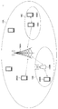
例えば、図2は、リレー端末を介した通信の概要について説明するための説明図である。リレー端末100Cとしては、例えば、ユーザが保持するスマートフォン等が想定され得る。また、リレー端末100Cを介して基地局100Aと通信を行うリモート端末200Cとしては、例えば、ウェアラブル端末等が想定され得る。リレー端末100Cは、基地局100Aとの間で、例えば、所謂LTE通信(以降では、「バックホールリンク通信」とも称する)を行う一方で、リモート端末200Cとの間でサイドリンク通信を行う。リモート端末200Cは、リレー端末100Cを経由して基地局100Aと通信を行う。この場合には、リレー端末100Cは、リモート端末200Cと基地局100Aとの間の通信を中継する通信装置となり得る。また、リモート端末200Cは、基地局100Aと直接通信を行うことも可能である。
For example, FIG. 2 is an explanatory diagram for explaining an outline of communication via a relay terminal. As the
一方で、ウェアラブル端末のようなリモート端末200Cと基地局100Aとの間のリレー通信においては、リモート端末200Cがリレー端末100Cを介して基地局100Aと通信を行うため、リレー端末100Cの存在が非常に重要となる。しかしながら、リレー端末100Cとして動作可能な端末装置は、多くの場合、基地局100Aのように常に固定的に存在しているものではないため、様々な理由でリレー端末100Cとして機能することが困難となる状況が発生する場合が想定され得る。具体的な一例として、リレー端末100Cとして動作可能な端末装置が、バッテリー不足により電源がオフの状態となった場合には、当該端末装置は、リレー端末100Cとして機能することが困難となる。そのため、このような不安定な状況下においても、サービスの継続性(Service continuity)を確保し、QoS(Quality of Service)を担保するような通信を実現することが非常に重要となる。即ち、リレー端末100Cとして動作可能な端末装置が、リレー端末100Cとして動作することが困難となった場合において、いかに通信を安定的に継続させるかがリレー通信における大きな課題となる。
On the other hand, in relay communication between a
これに対して、リモート端末200Cは、リレー端末100Cとの間のサイドリンク通信(PC5インターフェース)をサポートする一方で、基地局100Aとの間のDL(Downlink)/UL(Uplink)通信(Uuインターフェース)についてもサポートしている場合が考えられる。このような構成を利用することで、例えば、リモート端末200Cとリレー端末100Cとの間の通信が困難になった場合には、以下に示すリカバリ方法が考えられる。
(a)他のリレー端末100Cへとハンドオーバーする。
(b)リレー通信を停止して基地局100Aとの直接通信に切り替える。
On the other hand, the
(a) Handover to another
(b) The relay communication is stopped and switched to direct communication with the
以下に上記リカバリ方法の一例について、図3を参照して説明する。図3は、本実施形態に係るシステムの概要について説明するための説明図であり、リモート端末200Cとリレー端末100Cとの間のサイドリンク通信が困難になった場合におけるリカバリ方法の一例を示している。
An example of the above recovery method will be described below with reference to FIG. FIG. 3 is an explanatory diagram for explaining the outline of the system according to the present embodiment, and shows an example of a recovery method when side link communication between the
例えば、図3に示すように、リモート端末200Cは、リレー端末100C1を介して基地局100Aとリレー通信を行っている状況下において、当該リモート端末200Cと当該リレー端末100C1との通信が困難となったものとする。この場合、例えば、上記(a)として示したリカバリ方法に基づき、リレー端末100C1を介したリレー通信を、他のリレー端末100C2を介したリレー通信にハンドオーバーすることで、リモート端末200Cと基地局100Aとの間の通信をリカバリすることが可能である。また、他の一例として、上記(b)として示したリカバリ方法に基づき、リレー通信をやめ、リモート端末200Cが基地局100Aと直接通信を行うことで、リモート端末200Cと基地局100Aとの間の通信をリカバリすることも可能である。
For example, as shown in FIG. 3, the
しかしながら、上記(a)及び(b)として説明したいずれのリカバリ方法においても、リレー端末100Cがリレー端末として動作することが困難となった後にリカバリを行うような運用においては、サービスの継続性が損なわれる場合が想定され得る。そのため、リレー端末100Cが動作困難となる前に、上記(a)または(b)として示したリカバリが行われることがより望ましい。また、(a)として示したリカバリ方法においては、ハンドオーバーの際に、切り替え先となる他のリレー端末100C2に対してスムーズに接続が行われることがより望ましい。特に、ハンドオーバーに伴うパケットロスへの対応が必要となる。
However, in any of the recovery methods described in (a) and (b) above, the continuity of service is not good in the operation in which the
そこで、本開示では、所謂スマートフォン等のような移動体通信端末をリレー端末として利用したリレー通信(以降では、「モバイルリレー通信」とも称する)に向けた新たなRLM(Radio Link Monitoring)の仕組みの一例と、モバイルリレー通信を想定したハンドオーバーのための仕組みの一例とについて提案する。 Therefore, in the present disclosure, a new RLM (Radio Link Monitoring) mechanism for relay communication (hereinafter, also referred to as "mobile relay communication") using a mobile communication terminal such as a so-called smartphone as a relay terminal is provided. We propose an example and an example of a mechanism for handover assuming mobile relay communication.
<<2.構成例>>
続いて、本実施形態に係るシステムを構成する基地局100及び端末装置200の機能構成の一例について説明する。
<< 2. Configuration example >>
Subsequently, an example of the functional configuration of the
<2.1.基地局の構成例>
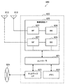
まず、図4を参照して、本開示の一実施形態に係る基地局100の構成を説明する。図4は、本開示の一実施形態に係る基地局100の構成の一例を示すブロック図である。図4を参照すると、基地局100は、アンテナ部110と、無線通信部120と、ネットワーク通信部130と、記憶部140と、処理部150とを含む。
<2.1. Base station configuration example>
First, the configuration of the
(1)アンテナ部110
アンテナ部110は、無線通信部120により出力される信号を電波として空間に放射する。また、アンテナ部110は、空間の電波を信号に変換し、当該信号を無線通信部120へ出力する。
(1)
The
(2)無線通信部120
無線通信部120は、信号を送受信する。例えば、無線通信部120は、端末装置へのダウンリンク信号を送信し、端末装置からのアップリンク信号を受信する。
(2)
The
また、前述したように、本実施形態に係るシステム1においては、端末装置がリレー端末(図1における無線通信装置100C)として動作し、リモート端末(図1における端末装置200C)と基地局との間の通信を中継する場合がある。このような場合には、例えば、リレー端末に相当する無線通信装置100Cにおける無線通信部120は、リモート端末との間でサイドリンク信号を送受信してもよい。
Further, as described above, in the
(3)ネットワーク通信部130
ネットワーク通信部130は、情報を送受信する。例えば、ネットワーク通信部130は、他のノードへの情報を送信し、他のノードからの情報を受信する。例えば、上記他のノードは、他の基地局及びコアネットワークノードを含む。
(3)
The
なお、前述したように、本実施形態に係るシステム1においては、端末装置がリレー端末として動作として動作し、リモート端末と基地局との間の通信を中継する場合がある。このような場合には、例えば、当該リレー端末に相当する無線通信装置100Cは、ネットワーク通信部130を備えていなくてもよい。
As described above, in the
(4)記憶部140
記憶部140は、基地局100の動作のためのプログラム及び様々なデータを一時的に又は恒久的に記憶する。
(4)
The
(5)処理部150
処理部150は、基地局100の様々な機能を提供する。処理部150は、通信処理部151と、情報取得部153と、判定部155と、通知部157とを含む。なお、処理部150は、これらの構成要素以外の他の構成要素をさらに含み得る。即ち、処理部150は、これらの構成要素の動作以外の動作も行い得る。
(5)
The
通信処理部151、情報取得部153、判定部155、及び通知部157の動作は、後に詳細に説明する。
The operations of the
<2.2.端末装置の構成例>
次に、図5を参照して、本開示の実施形態に係る端末装置200の構成の一例を説明する。図5は、本開示の実施形態に係る端末装置200の構成の一例を示すブロック図である。図5に示すように、端末装置200は、アンテナ部210と、無線通信部220と、記憶部230と、処理部240とを含む。
<2.2. Terminal device configuration example>
Next, an example of the configuration of the
(1)アンテナ部210
アンテナ部210は、無線通信部220により出力される信号を電波として空間に放射する。また、アンテナ部210は、空間の電波を信号に変換し、当該信号を無線通信部220へ出力する。
(1)
The
(2)無線通信部220
無線通信部220は、信号を送受信する。例えば、無線通信部220は、基地局からのダウンリンク信号を受信し、基地局へのアップリンク信号を送信する。
(2)
The
また、前述したように、本実施形態に係るシステム1においては、端末装置がリレー端末として動作し、リモート端末と基地局との間の通信を中継する場合がある。このような場合には、例えば、リモート端末として動作する端末装置200Cにおける無線通信部220は、リレー端末との間でサイドリンク信号を送受信してもよい。
Further, as described above, in the
(3)記憶部230
記憶部230は、端末装置200の動作のためのプログラム及び様々なデータを一時的に又は恒久的に記憶する。
(3)
The
(4)処理部240
処理部240は、端末装置200の様々な機能を提供する。例えば、処理部240は、通信処理部241と、情報取得部243と、判定部245と、通知部247とを含む。なお、処理部240は、これらの構成要素以外の他の構成要素をさらに含み得る。即ち、処理部240は、これらの構成要素の動作以外の動作も行い得る。
(4)
The
通信処理部241、情報取得部243、判定部245、及び通知部247の動作は、後に詳細に説明する。
The operations of the
<<3.技術的特徴>>
続いて、本実施形態の技術的特徴について説明する。
<< 3. Technical features >>
Subsequently, the technical features of the present embodiment will be described.
<3.1.RLMプロシジャ>
まず、図6を参照して、本実施形態に係るシステムにおける、モバイルリレー通信を想定したRLMプロシジャの概要について説明する。図6は、本実施形態に係るRLMプロシジャの一例について示したフローチャートである。なお、本説明では、リモート端末として動作する端末装置200C(以下、「リモート端末200C」とも称する)がRLMを実行し、実行結果に応じて基地局100Aとの通信に利用する無線リンクを切り替える動作に着目して説明する。
<3.1. RLM Procedure>
First, with reference to FIG. 6, the outline of the RLM procedure assuming mobile relay communication in the system according to the present embodiment will be described. FIG. 6 is a flowchart showing an example of the RLM procedure according to the present embodiment. In this description, the
まず、リモート端末200C(情報取得部243)は、例えば、サイドリンク、バックホールリンク等のような無線リンクの通信品質に関するパラメタ(例えば、パワー、SN比等)の測定を行う(S101)。なお、リモート端末200Cは、当該測定結果を示す情報を外部装置から取得してもよい。次いで、リモート端末200C(情報取得部243)は、無線リンクの通信品質に関するパラメタの測定結果に基づき、当該無線リンクの通信品質を推定する(S103)。例えば、リモート端末200Cは、当該測定結果を所定の閾値と比較することで、対象となる無線リンクの通信品質を推定する。なお、無線リンクの通信品質の推定に係る処理の詳細について詳細を別途後述する。また、リモート端末200Cは、当該推定結果を示す情報を外部装置から取得してもよい。また、無線リンクの通信品質の測定結果を示す情報や、当該無線リンクの通信品質の推定結果を示す情報が、「通信品質に関する情報」の一例に相当する。
First, the
次いで、リモート端末200C(判定部245)は、通信品質の推定結果に基づき、RLF(Radio Link Failure)へ移行するか否かを判定する(S105)。例えば、リモート端末200Cは、通信品質の推定結果が所定の閾値以下の状態が所定の期間以上継続した(換言すると、所定のタイマーが切れた)場合に、RLFへ移行する。なお、RLFの詳細については別途後述する。
Next, the
例えば、リモート端末200C(通信処理部241)は、RLFへ移行しない場合には(S105、NO)、既存の無線リンクを利用した通信を継続する(S107)。なお、この場合には、リモート端末200C(情報取得部243)は、当該無線リンクを対象としたRLMを継続する。
For example, when the
一方で、リモート端末200C(通信処理部241)は、RLFへの移行が決定された場合には(S105、YES)、基地局100Aとの間の通信に利用する無線リンクを切り替える(S109)。具体的な一例として、リモート端末200Cは、基地局100Aとの間のリレー通信に利用するリレー端末100Cを切り替えてもよい(即ち、リセレクションまたはハンドオーバーを行う)。また、他の一例として、リモート端末200Cは、リレー端末100Cを介したリレー通信を停止し、基地局100Aとの直接通信に切り替えてもよい(以降では、「eNBフォールバック」または「フォールバック」とも称する)。
On the other hand, when the
そして、リモート端末200C(通信処理部241)は、切り替え後の新規無線リンクを利用して基地局100Aとの通信を開始する。また、リモート端末200C(情報取得部243)は、切り替え後の新規無線リンクを対象としたRLMを開始してもよい(S111)。
Then, the
以上、図6を参照して、本実施形態に係るシステムにおける、モバイルリレー通信を想定したRLMプロシジャの概要について説明した。 As described above, with reference to FIG. 6, the outline of the RLM procedure assuming mobile relay communication in the system according to the present embodiment has been described.
<3.2.モバイルリレー通信に向けたRLM>
続いて、モバイルリレー通信に向けたRLMの詳細について説明する。
<3.2. RLM for mobile relay communication>
Subsequently, the details of RLM for mobile relay communication will be described.
(1)セルを対象としたRLMの概要
まず、モバイルリレー通信に向けたRLMについてよりわかりやすくするために、セルを対象としたRLMの一例について概要を説明する。例えば、RLMの主体となる通信装置は、RRC conected状態において、サービングセルを対象として通信品質のモニタリング(即ち、RLM)を実施する。ここで、当該通信装置は、例えば、RLMの対象となるリンクの通信品質が劣化し、所定の信頼性を満足することが困難と判断した場合にRLFへと移行する。
(1) Outline of RLM for cells First, in order to make it easier to understand RLM for mobile relay communication, an outline of an example of RLM for cells will be described. For example, the communication device that is the main body of the RLM performs communication quality monitoring (that is, RLM) for the serving cell in the RRC connected state. Here, the communication device shifts to RLF, for example, when it is determined that the communication quality of the link targeted by RLM deteriorates and it is difficult to satisfy a predetermined reliability.
ここで、図7を参照してRLFについて説明する。図7は、RLFの概要について説明するための説明図である。図7に示すように、通常のオペレーションが実行されている状態において、無線リンクの異常(例えば、通信品質の劣化等)が発見され、所定の期間(図4の期間T1)リカバリされない状態が継続した場合(First Phase)に、RLFへと移行する。 Here, RLF will be described with reference to FIG. FIG. 7 is an explanatory diagram for explaining the outline of the RLF. As shown in FIG. 7, in a state where the normal operation is being performed, the abnormal radio link (e.g., the communication quality deterioration) is found, a predetermined period (period T 1 of the FIG. 4) are not recovered state If it continues (First Phase), it shifts to RLF.
そして、RLFへの移行後、さらに所定の期間(図4の期間T2)リカバリされない状態が継続した場合(Second Phase)には、RRC idle modeへと遷移する。この場合には、通信装置は、例えば、新たにリンクをセットアップするために、ハンドオーバーやセルリレクション等の対応を取ることとなる。 Then, after the transition to the RLF, the further predetermined time period (Fig period T 2 of the 4) If the recovery is not state continues (Second Phase), transition to RRC idle mode. In this case, the communication device will take measures such as handover and cell retraction in order to set up a new link, for example.
(2)モバイルリレー通信におけるRLM
続いて、モバイルリレー通信におけるRLMについて説明する。モバイルリレー通信が行われている環境下では、各端末装置(即ち、リレー端末100C及びリモート端末200C)は、所定の無線リンクについて通信品質の測定を継続的に実行する。
(2) RLM in mobile relay communication
Next, RLM in mobile relay communication will be described. In an environment where mobile relay communication is performed, each terminal device (that is,
具体的な一例として、リレー端末100Cは、基地局100Aとの間のダウンリンク(換言すると、バックホールリンク)の通信品質を測定してもよい。また、リレー端末100Cは、リモート端末200Cとの間のサイドリンク(換言すると、アクセスリンク)の通信品質を測定してもよい。また、リモート端末200Cは、基地局100Aとの間のダウンリンクの通信品質を測定してもよい。また、リモート端末200Cは、リレー端末100Cとの間のサイドリンクの通信品質を測定してもよい。
As a specific example, the
なお、リモート端末200Cと基地局100Aとの間のリレー端末100Cを介したリレー通信のための一連の無線リンク(即ち、サイドリンク及びバックリンク)が、「第2の無線リンク」の一例に相当する。また、当該第2の無線リンクのうち、リモート端末200Cとリレー端末100Cとの間の通信のための無線リンク(即ち、サイドリンク)が、「第3の無線リンク」の一例に相当する。また、当該第2の無線リンクのうち、リレー端末100Cと基地局100Aとの間の通信のための無線リンク(即ち、バックホールリンク)が、「第4の無線リンク」の一例に相当する。なお、リモート端末200Cと基地局100Aとの間の直接通信のための無線リンク(即ち、Uuリンク)は、「第1の無線リンク」の一例に相当する。
A series of wireless links (that is, side links and back links) for relay communication between the
次いで、各無線リンクの通信品質を測定する方法の一例について、無線リンクごとに以下に説明する。具体的な一例として、ダウンリンクの通信品質の測定には、CRS(Cell−specific reference signal)が用いられる。 Next, an example of a method for measuring the communication quality of each wireless link will be described below for each wireless link. As a specific example, a CRS (Cell-specific reference signal) is used to measure the communication quality of the downlink.
また、サイドリンクの通信品質の測定には、例えば、リレーに固有の(即ち、Relay specificな)リファレンス信号が用いられる。これは、DMRS(Demodulation Reference Signal)やCRSをリレー端末向けに修正したもの等を用いることで実現することが可能である。より具体的な一例として、リレー端末の識別情報を用いることで、当該リレーに固有のリファレンス信号が生成されてもよい。 Further, for measuring the communication quality of the side link, for example, a reference signal specific to the relay (that is, Relay specific) is used. This can be realized by using a DMRS (Demodulation Reference Signal) or a modified CRS for a relay terminal. As a more specific example, a reference signal unique to the relay may be generated by using the identification information of the relay terminal.
次いで、各無線リンクの通信品質を推定する方法の一例について説明する。各無線リンクの通信品質の測定後には、各端末装置は、当該測定結果に基づき無線リンクの通信品質の推定を行う。 Next, an example of a method of estimating the communication quality of each wireless link will be described. After measuring the communication quality of each wireless link, each terminal device estimates the communication quality of the wireless link based on the measurement result.
例えば、ダウンリンクについての通信品質の推定は、当該ダウンリンクを介して、信頼性のある通信が可能か否かの基準に基づき判定される(例えば、PDCCH BLERが10%以下、または2%以下等)。 For example, the estimation of communication quality for a downlink is determined based on the criteria for whether reliable communication is possible via the downlink (for example, PDCCH BLER is 10% or less, or 2% or less). etc).
また、モバイルリレー通信においては、リレー端末100Cと基地局100Aとの間のダウンリンクの通信品質のみに限らず、リレー端末100Cとリモート端末200Cとの間のサイドリンクの通信品質についても考慮する必要がある。特に、リモート端末200Cは、基地局100Aとの間のダウンリンクの通信品質に加えて、リレー端末100Cとの間のサイドリンクと、当該リレー端末100Cと基地局100Aとの間のバックホールリンクについても通信品質を推定する必要がある。
Further, in mobile relay communication, it is necessary to consider not only the communication quality of the downlink between the
例えば、以下に、バックホールリンク及びサイドリンクの通信品質の状態に応じて最終的なリンクの評価結果と、その場合の対応の一例についてまとめる。以下に示す表において、「○」は通信の信頼性に問題が無い場合を示しており、「×」は通信の信頼性に問題が生じている場合を示している。 For example, the final evaluation result of the link according to the communication quality status of the backhaul link and the side link and an example of the correspondence in that case are summarized below. In the table shown below, "○" indicates that there is no problem in communication reliability, and "x" indicates that there is a problem in communication reliability.

(3)バックホールリンクの通信品質推定
続いて、バックホールリンクの通信品質を推定するための手法の一例について説明する。3GPPのRelease13におけるPublic safety向けのUE−to−Network relayにおいては、Relay Uuのバックホールリンクの強さは、Relay selection/reselectionに考慮しないという合意がされている。そのため、PC5のリンクの通信品質のみに基づきリレー端末の選択が行われている。このような前提のもとで、リモート端末、リレー端末、及び基地局のそれぞれにおいて、バックホールリンクの通信品質を推定する手法の一例について以下に説明する。
(3) Estimating the communication quality of the backhaul link Next, an example of a method for estimating the communication quality of the backhaul link will be described. In the UE-to-Network relay for public safety in Release 13 of 3GPP, it has been agreed that the strength of the backhaul link of Relay Uu is not considered in Relay selection / reselection. Therefore, the relay terminal is selected based only on the communication quality of the link of the PC5. Based on such a premise, an example of a method for estimating the communication quality of the backhaul link in each of the remote terminal, the relay terminal, and the base station will be described below.
(3−1)リモート端末側でバックホールリンクの通信品質の推定を行う場合
まず、リモート端末200Cが、バックホールリンクの通信品質を推定する場合の一例について説明する。
(3-1) Case of Estimating Backhaul Link Communication Quality on the Remote Terminal Side First, an example of a case where the
(通信品質の推定方法)
具体的な一例として、リモート端末200Cは、リレー端末100Cと基地局100Aとの間のバックホールリンクを監視することで、当該バックホールリンクの通信品質を推定する。特に、モバイルリレー通信においては、リモート端末200Cとリレー端末100Cとは比較的近傍に位置することが予想されるため、上記したように、リモート端末200Cが、リレー端末100Cと基地局100Aとの間のバックホールリンクの通信品質を推定することは比較的容易と考えられる。
(Communication quality estimation method)
As a specific example, the
なお、リモート端末200C(情報取得部243)が、バックホールリンクの通信品質を推定するための基準は、当該リモート端末200Cが基地局100Aとの間のダウンリンクの通信品質を推定するための基準とは異なる。具体的には、バックホールリンクの通信品質が劣化または向上したことを判定するための基準(閾値)は、ダウンリンクの通信品質を判定する基準(閾値)に比べて、より小さい通信品質の変化に基づき判定されるように設定される。
The standard for the
より具体的な一例として、ダウンリンク通信の品質推定に用いられる基準としては、以下に説明するQout_q及びQin_qが挙げられる。Qout_q及びQin_qは、無線リンク品質が同期内(in-sync)を示すか同期外(out-of-sync)を示すかを評価するための基準Qout及びQinに応じて設定され得る。具体的には、Qout_qは、通信品質の悪さを示す基準(閾値)に相当し、例えば、ダウンリンク通信の通信品質が所定の品質を具備しなくなったか否かの評価に用いられる。また、Qin_qは、通信品質の良さを示す基準(閾値)に相当し、例えば、ダウンリンク通信の通信品質が所定の品質を具備しているか否かの評価に用いられる。 As a more specific example, the criteria used for quality estimation of downlink communication include Qout_q and Qin_q described below. Qout_q and Qin_q can be set according to the criteria Qout and Qin for assessing whether the radio link quality indicates in-sync or out-of-sync. Specifically, Qout_q corresponds to a standard (threshold value) indicating poor communication quality, and is used, for example, to evaluate whether or not the communication quality of downlink communication does not meet a predetermined quality. Further, Qin_q corresponds to a standard (threshold value) indicating good communication quality, and is used, for example, to evaluate whether or not the communication quality of downlink communication has a predetermined quality.
ここで、図8〜図10を参照して、リモート端末200Cがバックホールリンクの通信品質を推定するための基準の一例についてより詳しく説明する。
Here, an example of a standard for the
無線リンク品質が同期内(in-sync)を示すか同期外(out-of-sync)を示すかについては、下りリンク無線リンク品質と閾値との比較によって評価される。当該閾値には、同期内(in-sync)を判断するために用いられる閾値Qinと、同期外(out-of-sync)を判断するために用いられる閾値Qoutが定められている。 Whether the radio link quality indicates in-sync or out-of-sync is evaluated by comparing the downlink radio link quality with the threshold value. The threshold is defined as a threshold Qin used for determining in-sync and a threshold Qout used for determining out-of-sync.
例えば、図8は、無線リンク品質の時間変動と同期内及び同期外それぞれの状態との一例について説明するための説明図である。図8では、同期内(in-sync)状態から同期外(out-of-sync)状態に遷移する場合の一例が示されている。具体的には、無線リンク品質が閾値Qoutよりも低下した場合には、端末装置の物理層は、上位層に同期外(out-of-sync)を報告する。次の評価タイミングにおいても、無線リンク品質が閾値Qinよりも上回らない場合は、端末装置の物理層は、上位層に同期外(out-of-sync)を報告する。RLF(Radio Link Failure)に関連するパラメータによって設定された所定の回数(N310,N313)連続して同期外(out-of-sync)が報告された場合には、上位層は、物理層に問題があると判断し、RLFタイマー(T310,T313)を開始させる。当該RLFタイマーが超過する前に、RLFに関連するパラメータによって設定された所定の回数(N311,N314)連続して同期内(in-sync)が報告された場合には、上位層は、物理層の問題が回復されたと判断し、RLFタイマー(T310,T313)を停止させる。一方で、RLFタイマーが超過した場合には、RLFが発生し、端末装置はRRC接続(RRC_CONNECTED)モードからの離脱もしくは接続再確立を行う。また、プライマリーセルのRLFタイマー(T310)が超過した場合には、40ms以内に端末装置の送信電力が切られる。また、プライマリーセカンダリーセルのRLFタイマー(T313)が超過した場合には、40ms以内にプライマリーセカンダリーセルの送信電力が切られる。 For example, FIG. 8 is an explanatory diagram for explaining an example of the time variation of the radio link quality and the in-synchronous and out-of-synchronization states. FIG. 8 shows an example of a transition from an in-synchronous state to an out-of-sync state. Specifically, when the wireless link quality is lower than the threshold Qout, the physical layer of the terminal device reports out-of-sync to the upper layer. If the wireless link quality does not exceed the threshold value Qin even at the next evaluation timing, the physical layer of the terminal device reports out-of-sync to the upper layer. If out-of-sync is reported consecutively for a predetermined number of times (N310, N313) set by parameters related to RLF (Radio Link Failure), the upper layer has a problem with the physical layer. It is determined that there is, and the RLF timers (T310, T313) are started. If a predetermined number of times (N311, N314) consecutively in-sync (in-sync) set by the parameters related to RLF are reported before the RLF timer is exceeded, the upper layer is the physical layer. It is judged that the problem of the above has been recovered, and the RLF timers (T310, T313) are stopped. On the other hand, when the RLF timer is exceeded, RLF occurs, and the terminal device disconnects from the RRC connection (RRC_CONNECTED) mode or reestablishes the connection. Further, when the RLF timer (T310) of the primary cell is exceeded, the transmission power of the terminal device is cut off within 40 ms. Further, when the RLF timer (T313) of the primary secondary cell is exceeded, the transmission power of the primary secondary cell is cut off within 40 ms.
閾値Qoutは、例えば、PCFICHエラーを考慮した仮想PDCCH送信のブロックエラーレートが10%に相当する水準で定義される。また、閾値Qinは、例えば、閾値Qoutよりも受信品質が十分に良好で、かつ、PCFICHエラーを考慮した仮想PDCCH送信のブロックエラーレートが2%に相当する水準で定義される。 The threshold Qout is defined, for example, at a level at which the block error rate of virtual PDCCH transmission considering the PCFICH error corresponds to 10%. Further, the threshold value Qin is defined, for example, at a level where the reception quality is sufficiently better than the threshold value Qout and the block error rate of virtual PDCCH transmission in consideration of the PCFICH error corresponds to 2%.
端末装置は、全ての無線フレームの無線リンク品質を所定の時間区間で測定する。また、端末装置は、DRX(Discontinuous Reception)モードが設定された場合には、全てのDRX区間の無線リンク品質を所定の時間区間で測定してもよい。 The terminal device measures the radio link quality of all radio frames in a predetermined time interval. Further, when the DRX (Discontinuous Reception) mode is set, the terminal device may measure the radio link quality of all DRX sections in a predetermined time section.
端末装置が無線リンク品質を評価するための所定の時間区間としては、同期内(in-sync)を評価する時間区間TEvaluate_Qinと、同期外(out-of-sync)を評価する時間区間TEvaluate_Qoutとが、それぞれ個別に定義される。 The predetermined time interval for the terminal device to evaluate the wireless link quality is the time interval T Evaluate _Q in for evaluating in-sync and the time interval for evaluating out-of-sync. T Evaluate _Q out and each are defined individually.
時間区間TEvaluate_Qoutは、同期外(out-of-sync)を評価するために定義された最小測定区間であり、例えば、所定の期間(例えば、200ms)、またはDRXサイクルの長さ、等が設定され得る。なお、前記の一例は最小区間であり、端末装置は、前記の一例よりも長い期間にわたって測定を行ってもよい。 The time interval T Evaluate _Q out is the minimum measurement interval defined to evaluate out-of-sync, eg, a predetermined period (eg, 200 ms), or the length of the DRX cycle, etc. Can be set. It should be noted that the above example is the minimum section, and the terminal device may perform measurement over a longer period than the above example.
時間区間TEvaluate_Qinは、同期内(in-sync)を評価するために定義された最小測定区間であり、例えば、所定の期間(例えば、100ms)、またはDRXサイクルの長さ、等が設定され得る。なお、前記の一例は最小区間であり、端末装置は、前記の一例よりも長い期間にわたって測定を行ってもよい。 The time interval T Evaluate _Q in is the minimum measurement interval defined to evaluate in-sync, and is set, for example, a predetermined period (for example, 100 ms), the length of the DRX cycle, and the like. Can be done. It should be noted that the above example is the minimum section, and the terminal device may perform measurement over a longer period than the above example.
同期内(in-sync)および同期外(out-of-sync)の報告の期間は、最低でも10ms(1無線フレーム)分が設定され得る。 The in-synchronous (in-sync) and out-of-sync (out-of-sync) reporting periods can be set to at least 10 ms (1 radio frame).
続いて、図9を参照して、リモート端末におけるバックホールリンク品質の推定についてより詳細に説明する。図9は、リモート端末及びリレー端末においける無線リンク品質の時間変動と、リモート端末における同期内及び同期外それぞれの状態との一例について説明するための説明図である。図9において、参照符号g11は、リレー端末におけるバックホールリンの通信品質の測定結果を示している。また、参照符号g13は、リモート端末におけるリレー端末のバックホールリンクの通信品質の測定(推定)結果を示している。 Subsequently, with reference to FIG. 9, the estimation of the backhaul link quality in the remote terminal will be described in more detail. FIG. 9 is an explanatory diagram for explaining an example of the time variation of the wireless link quality in the remote terminal and the relay terminal and the in-synchronization and out-of-synchronization states in the remote terminal. In FIG. 9, reference numeral g11 indicates the measurement result of the communication quality of the backhaul phosphorus in the relay terminal. Further, reference numeral g13 indicates the measurement (estimation) result of the communication quality of the backhaul link of the relay terminal in the remote terminal.
リモート端末におけるリレー端末バックホールリンク品質測定の場合、リモート端末はバックホールリンクと同期はしていない場合が考えられるため、無線リンク品質が同期内(in-sync)を示すか同期外(out-of-sync)を示すかというパラメータではなく、無線リンク品質が一定の品質以上かどうかで判断を行う。ここではそれぞれ品質内(In-quality)、品質外(Out-of-quality)として定義している。図9に示す例では、リモート端末におけるリレー端末のバックホールリンク品質がIn-qualityからOut-of-quality状態に遷移する一例が示されている。なお、このときリレー端末は、バックホールリンクの品質測定を同時に行っている。また、当該品質測定は、前述のIn-sync,Out-of-syncを用いて実施される。 In the case of relay terminal backhaul link quality measurement at the remote terminal, the remote terminal may not be synchronized with the backhaul link, so the wireless link quality indicates in-sync or out-sync. Judgment is made based on whether the wireless link quality is above a certain level, not on the parameter of indicating of-sync). Here, they are defined as in-quality and out-of-quality, respectively. In the example shown in FIG. 9, an example in which the backhaul link quality of the relay terminal in the remote terminal transitions from the in-quality to the out-of-quality state is shown. At this time, the relay terminal simultaneously measures the quality of the backhaul link. In addition, the quality measurement is carried out using the above-mentioned In-sync and Out-of-sync.
In-quality,Out-of-quality用の閾値Qin_q及びQout_qはリレー端末においてバックホールリンクの品質がIn-sync,Out-of-syncになるかどうかをリモート端末側で推定できるような値として設定される。例えば、リレー端末の閾値Qin,Qoutに対して、所定のOffset値に基づきQin_q,Qout_qが設定されてもよい。また、他の一例として、リモート端末に対して、直接Qin_q,Qout_qが設定されてもよい。 The thresholds Qin_q and Qout_q for In-quality and Out-of-quality are set as values that allow the remote terminal to estimate whether the quality of the backhaul link is In-sync or Out-of-sync at the relay terminal. Will be done. For example, Qin_q and Qout_q may be set for the threshold values Qin and Qout of the relay terminal based on a predetermined Offset value. Further, as another example, Qin_q and Qout_q may be set directly for the remote terminal.
より具体的には、Qout_qは、リレー端末の閾値Qoutをリモート端末側で推定可能となるように設定される。そのため、例えば、図9において、1st out-of-syncのタイミングに示すように、リレー端末側においてバックホールリンクの通信品質の測定結果がQout以下となった場合に、リモート端末側においても当該バックホールリンクの通信品質の推定結果がQout_q以下となるように、Qout_qが設定されることが望ましい。 More specifically, Qout_q is set so that the threshold Qout of the relay terminal can be estimated on the remote terminal side. Therefore, for example, in FIG. 9, as shown in the timing of the 1 st out-of-sync, when the communication quality measurement result of the backhaul link in the relay terminal is equal to or less than Qout, the even remote terminal side It is desirable that Qout_q is set so that the estimation result of the communication quality of the backhaul link is Qout_q or less.
また、リモート端末側では、リレー端末のバックホールリンクの通信品質を推定するための基準Qin_q,Qout_qとは別に、基地局との間の無線リンク(即ち、ダウンリンク)について同期外及び同期内を評価するためのQin,Qoutが設定されていてもよい。例えば、図10は、リモート端末及びリレー端末においける無線リンク品質の時間変動と、リモート端末における同期内及び同期外それぞれの状態との他の一例について説明するための説明図である。なお、図10において、参照符号g11及びg13は、図9において同様の符号が付されたグラフを示すものとする。また、図10に示す例では、図9に示す例と同様に、リレー端末側において通信品質の測定結果がQout以下となる1st out-of-syncのタイミングにおいて、リモート端末側においても通信品質の推定結果がQout_q以下となるように、Qout_qが設定されている。 In addition, on the remote terminal side, apart from the criteria Qin_q and Qout_q for estimating the communication quality of the backhaul link of the relay terminal, the wireless link (that is, downlink) with the base station is out of synchronization and in synchronization. Qin and Qout for evaluation may be set. For example, FIG. 10 is an explanatory diagram for explaining another example of the time variation of the wireless link quality in the remote terminal and the relay terminal, and the in-synchronization and out-of-synchronization states in the remote terminal. In addition, in FIG. 10, reference numerals g11 and g13 indicate graphs with similar reference numerals in FIG. Further, in the example shown in FIG. 10, similarly to the example shown in FIG. 9, the timing measurement result of the communication quality of the 1 st out-of-sync as a less Qout in the relay terminal, communication even in the remote terminal Quality Qout_q is set so that the estimation result of is Qout_q or less.
前述したように、Qout_qは、リモート端末がダウンリンクについて同期外の状態にあるか否かを評価するためのQoutとは異なる値が設定されてもよい。具体的には、図10に示すように、Qout_qは、当該Qoutに基づきダウンリンクについて同期外の状態に遷移させる通信品質に比べて、より高い通信品質においてOut-of-qualityの状態に遷移させるように(即ち、Qoutに比べてより低いBLERに対応する値となるように)設定されていてもよい。これにより、バックホールリンクの通信品質が劣化した場合(g111)に、ダウンリンク用に設定された閾値であるQoutに基づく評価(g133)よりも先に、バックホールリンク用に設定された閾値Qout_qに基づく評価(g131)が実行されることとなる。また、Qin_qとして、リモート端末がQinに基づきダウンリンクについて同期内の状態に遷移させる通信品質に比べて、より低い通信品質においてIn-qualityの状態に遷移させるように(即ち、Qinに比べてより高いBLERに対応する値となるように)設定されていてもよい。これにより、バックホールリンクの通信品質が向上した場合に、ダウンリンク用に設定された閾値であるQinに基づく評価よりも先に、バックホールリンク用に設定された閾値Qin_qに基づく評価が実行されることとなる。 As described above, Qout_q may be set to a value different from Qout for evaluating whether or not the remote terminal is out of sync with the downlink. Specifically, as shown in FIG. 10, Qout_q transitions to the Out-of-quality state at a higher communication quality than the communication quality that transitions the downlink to the out-of-synchronous state based on the Qout. (Ie, it may be set to a value corresponding to a lower BLER than Qout). As a result, when the communication quality of the backhaul link deteriorates (g111), the threshold value Qout_q set for the backhaul link is prior to the evaluation based on Qout (g133), which is the threshold value set for the downlink. The evaluation based on (g131) will be executed. Also, as Qin_q, the remote terminal transitions to the In-quality state at a lower communication quality than the communication quality at which the downlink transitions to the in-synchronous state based on Qin (that is, more than Qin). It may be set (to have a value corresponding to a high BLER). As a result, when the communication quality of the backhaul link is improved, the evaluation based on the threshold value Qin_q set for the backhaul link is executed before the evaluation based on the threshold value Qin_q set for the downlink. The Rukoto.
なお、上記では、バックホールリンクの通信品質の測定に着目して説明した。一方で、サイドリンクの通信品質の測定(推定)についても同様に、端末装置間で同期が行われない場合があるため、In-quality、Out-of-qualityのパラメータを用いて通信品質の測定(推定)が実施されてもよい。ただし、In-quality、Out-of-qualityのパラメータに替えて、同期内(in-sync)、同期外(out-of-sync)のパラメータを代用することも可能である。 In the above description, the measurement of the communication quality of the backhaul link has been focused on. On the other hand, regarding the measurement (estimation) of the communication quality of the side link, similarly, synchronization may not be performed between the terminal devices, so the communication quality is measured using the parameters of In-quality and Out-of-quality. (Estimation) may be carried out. However, instead of the In-quality and Out-of-quality parameters, it is possible to substitute the in-synchronous (in-sync) and out-of-sync (out-of-sync) parameters.
また、リモート端末200Cがバックホールリンクの通信品質を推定(判定)するための基準(閾値)は、複数段階に分けて設定されていてもよい。より具体的な一例として、当該閾値は、Low、Mid、及びHighの3段階に分けて設定されていてもよい。
Further, the reference (threshold value) for the
また、リモート端末200Cがバックホールリンクの通信品質を推定(判定)するための基準(閾値)は、例えば、基地局100Aから当該リモート端末200Cに通知されてもよい。この場合には、例えば、当該基準を示す情報は、RRC signalingに基づき基地局100Aからリモート端末200Cに通知されてもよい。また、他の一例として、当該基準(閾値)は、リモート端末200CにPre-configureされていてもよい。
Further, the reference (threshold value) for the
また、リモート端末200Cがバックホールリンクの通信品質を推定(判定)するための基準(閾値)は、当該リモート端末200Cが自身で算出することで設定されてもよい。この場合には、リモート端末200Cは、例えば、自身に設定されているダウンリンクの通信品質を推定するための閾値(以下、「ダウンリンク用の閾値」とも称する)に基づき、バックホールリンクの通信品質を推定するための閾値(以下、「バックホールリンク用の閾値」とも称する)を算出してもよい。
Further, the reference (threshold value) for the
より具体的な一例として、リモート端末200Cは、ダウンリンク用の閾値に対してWeightを乗ずることで、バックホールリンク用の閾値を算出してもよい。なお、Weightは、例えば、リモート端末200Cとリレー端末100Cとの間の距離、及び受信電力(パスロス)等のパラメタに基づき算出されてもよい。
As a more specific example, the
(タイマーの設定)
また、リモート端末200Cが、バックホールリンクの通信品質を推定するためのタイマーが新たに設定されてもよい。このタイマーは、例えば、バックホールリンクのRLFを検出するために使用され得る。また、このタイマーには、リモート端末200Cに設定されている、ダウンリンクのRLFの検出に使用されるタイマーとは異なる値が設定されていてもよい。
(Timer setting)
Further, the
以上、リモート端末200Cが、バックホールリンクの通信品質を推定する場合の一例について説明した。
The example of the case where the
(3−2)リレー端末側でバックホールリンクの通信品質の推定を行う場合
続いて、リレー端末100Cが、バックホールリンクの通信品質を推定し、当該推定結果をリモート端末200Cに通知する場合の一例について説明する。
(3-2) When estimating the communication quality of the backhaul link on the relay terminal side Next, when the
(通信品質の推定方法)
まず、リレー端末100Cが、バックホールリンク(即ち、基地局100Aとの間の無線リンク)の通信品質を推定する方法の一例について説明する。例えば、リレー端末100C(情報取得部153)は、ダウンリンク(即ち、バックホールリンク)の通信品質を推定するために設定された基準(閾値)に基づき、バックホールリンクの通信品質を推定してもよい。
(Communication quality estimation method)
First, an example of a method in which the
また、他の一例として、リレー端末100Cがバックホールリンクの通信品質を推定するための基準(閾値)が新たに設定されてもよい。なお、当該新たな基準は、例えば、リレー端末100C(通知部157)が、バックホールリンクの通信品質の推定結果をリモート端末200Cに通知するために用いられる。また、当該新たな基準として、リレー端末100Cに設定されたダウンリンクの通信品質を推定するための基準とは異なる値が設定されてもよい。また、この場合には、当該新たな基準は、基地局100Aからリレー端末100Cに対して通知されてもよい。具体的には、当該新たな基準(閾値)を示す情報は、例えば、RRC signalingに基づき基地局100Aからリレー端末100Cに通知されてもよい。また、他の一例として、当該新たな基準(閾値)は、リレー端末100CにPre-configureされていてもよい。
Further, as another example, a reference (threshold value) for the
(通信品質の推定結果の通知方法)
次いで、リレー端末100C(通知部157)が、バックホールリンクの通信品質の推定結果に関する情報をリモート端末200Cに通知する方法の一例について説明する。
(Notification method of communication quality estimation result)
Next, an example of a method in which the
例えば、リレー端末100Cは、バックホールリンクの通信品質の推定結果を示す情報自体をリモート端末200Cに通知してもよい。また、他の一例として、リレー端末100Cは、バックホールリンクの通信品質の推定結果を量子化してリモート端末200Cに通知してもよい。具体的な一例として、リレー端末100Cは、バックホールリンクの通信品質の測定結果を所定の閾値と比較することで、通信品質の良否を示す情報や、通信品質の高さ(例えば、高/中/低)を示す情報をリモート端末200Cに通知してもよい。また、リレー端末100Cは、例えば、バックホールリンクの通信品質が所定の品質以下となった場合にのみ、リモート端末200Cに対して通知を行ってもよい。
For example, the
また、リレー端末100Cは、バックホールリンクの通信品質の推定結果に加えて、各種付加情報をリモート端末200Cに通知してもよい。具体的な一例として、リレー端末100Cは、通信品質の測定環境を示す情報をリモート端末200Cに通知してもよい。なお、通信品質の測定環境を示す情報としては、例えば、測定時間、測定に使用したリソース、及び測定対象となるアンテナポート等を示す情報が挙げられる。また、リレー端末100Cは、バックホールリンクの通信品質の推定結果を反映させることが可能な期間(即ち、有効期間)を設定し、当該有効期間を示す情報をリモート端末200Cに通知してもよい。具体的な一例として、リレー端末100Cは、当該通知を受信してから10サブフレームの期間を有効期間として設定してもよく、この場合には、有効期間が10サブフレームであることをリモート端末200Cに通知することとなる。なお、上記では、リレー端末100Cがリモート端末200Cに対してバックホールリンクの通信品質に関する情報を通知する場合に着目して説明したが、リモート端末200Cがリレー端末200Cに対してバックホールリンクの通信品質に関する情報を通知してもよい。
Further, the
(通知のためのリンク及びリソース)
続いて、リレー端末100Cが、バックホールリンクの通信品質の推定結果に関する情報をリモート端末200Cに通知するために利用する無線リンクやリソースの一例について説明する。
(Links and resources for notification)
Subsequently, an example of a wireless link and a resource used by the
例えば、リレー端末100Cは、サイドリンクを利用することで、バックホールリンクの通信品質の推定結果に関する情報を、リモート端末200Cに直接通知してもよい。この場合には、当該通知のためのリソースプールは、基地局100A(通信処理部151)またはリレー端末100C(通信処理部151)により設定されてもよい。また、当該リソースプールに関する情報は、例えば、RRC signalingに基づき基地局100Aからリモート端末200Cに通知されてもよい。また、他の一例として、当該リソースプールに関する情報は、RRC signalingに基づきリレー端末100Cからリモート端末200Cに通知されてもよい。また、このときリレー端末100Cは、報知情報(PSBCH:Physical Sidelink Broadcast Channel)を用いて、当該リソースプールに関する情報をリモート端末200Cに通知してもよい。また、他の一例として、当該リソースプールに関する情報が、リモート端末200CにPre-configureされていてもよい。
For example, the
また、他の一例として、リレー端末100Cは、バックホールリンクの通信品質の推定結果に関する情報を、基地局100Aを介して間接的にリモート端末200Cに通知してもよい。この場合には、リレー端末100Cは、例えば、RRC signalingに基づき、バックホールリンクの通信品質の推定結果に関する情報を基地局100Aに通知してもよい。また、基地局100Aは、リレー端末100Cから通知された当該情報を、例えば、RRC signalingに基づきリモート端末200Cに通知すればよい。
Further, as another example, the
(通知タイミング)
続いて、リレー端末100C(通知部157)が、バックホールリンクの通信品質の推定結果に関する情報をリモート端末200Cに通知するタイミングの一例について説明する。
(Notification timing)
Subsequently, an example of the timing at which the
例えば、リレー端末100Cは、バックホールリンクの通信品質の推定結果が所定の基準(閾値)を超えた場合に、当該通信品質の推定結果に関する情報をリモート端末200Cに通知してもよい。より具体的な一例として、リレー端末100Cは、バックホールリンクの通信品質の推定結果に基づき、RLFに移行することが推定された場合に、リモート端末200Cに対して通知を行ってもよい。なお、バックホールリンクの通信品質の推定結果を判定するための基準(閾値)を示す情報は、例えば、RRC signalingに基づき基地局100Aからリレー端末100Cに通知されてもよい。また、他の一例として、当該基準(閾値)を示す情報は、リレー端末100CにPre-configureされていてもよい。
For example, the
また、他の一例として、基地局100Aにより、リレー端末100Cに対して通知タイミングが設定されてもよい。具体的な一例として、基地局100Aは、バックホールリンクの通信品質の推定結果を示す情報が準静的に通知されるように、通知タイミングをスケジューリングしてもよい(Semi-persistent scheduling)。この場合には、基地局100Aは、リレー端末100Cに対してレポートを行うリソースプールを設定してもよい。また、基地局100Aは、リレー端末100Cに対して、レポートタイミング及びレポート間隔を設定してもよい。例えば、レポートタイミングは、基準点に対するオフセット情報がリレー端末100Cに通知されることで、当該リレー端末100Cに設定されてもよい。また、基地局100Aは、DCI(Downlink Control Information)を利用して、レポートのActivation/Deactivationを行ってもよい。また、他の一例として、基地局100Aは、バックホールリンクの通信品質の推定結果を示す情報が動的に通知されるように、通知タイミングをスケジュールリングしてもよい(即ち、リレー端末100Cに指示してもよい)。なお、レポートタイミング及びレポート間隔については、リレー端末100CにPre-configureされていてもよい。
Further, as another example, the
(タイマーの設定)
また、リレー端末100Cが、バックホールリンクの通信品質を推定するためのタイマーが新たに設定されてもよい。このタイマーは、例えば、バックホールリンクのRLFを検出するために使用され得る。また、このタイマーには、リレー端末100Cに設定されている、ダウンリンクのRLFの検出に使用されるタイマーとは異なる値が設定されていてもよい。
(Timer setting)
Further, the
以上、リレー端末100Cが、バックホールリンクの通信品質を推定し、当該推定結果をリモート端末200Cに通知する場合の一例について説明した。
The example of the case where the
(3−3)基地局側でバックホールリンクの通信品質の推定を行う場合
続いて、基地局100Aが、バックホールリンクの通信品質を推定し、当該推定結果をリモート端末200Cに通知する場合の一例について説明する。
(3-3) When the base station side estimates the communication quality of the backhaul link Next, when the
この場合には、例えば、基地局100Aは、リレー端末100Cからのアップリンク信号の通信品質を測定し、当該測定結果に基づきバックホールリンクの通信品質を推定してもよい。なお、このとき基地局100Aは、例えば、アップリンク信号におけるPUSCH(Physical Uplink Shared Channel)、PUCCH(Physical Uplink Control Channel)、SRS(Sounding Reference Signal)のうちの少なくともいずれかを用いて、アップリンクの通信品質を測定してもよい。
In this case, for example, the
以上、基地局100Aが、バックホールリンクの通信品質を推定し、当該推定結果をリモート端末200Cに通知する場合の一例について説明した。
The example of the case where the
(4)サイドリンクの通信品質推定
続いて、サイドリンクの通信品質を推定するための手法の一例について説明する。リモート端末200Cまたはリレー端末100Cは、サイドリンクの通信品質を推定し、推定結果に応じてRLFへの移行の判定(即ち、RLFの検出)を行う。このとき、リモート端末200Cまたはリレー端末100Cは、上述したバックホールリンクの通信品質の推定結果を加味したうえで、RLFへの移行の判定を行ってもよい。そこで、サイドリンクの通信品質を推定するための手法の一例について、以下に、リモート端末200CがサイドリンクのRLMを行う場合と、リレー端末100CがサイドリンクのRLMを行う場合とに分けて説明する。
(4) Estimating the communication quality of the side link Next, an example of a method for estimating the communication quality of the side link will be described. The
(4−1)リモート端末200CがサイドリンクのRLMを行う場合
まず、リモート端末200Cが、サイドリンクのRLMを行う、即ち、サイドリンクの通信品質を推定し、当該推定結果に応じてRLFへの移行の判定を行う場合の一例について説明する。
(4-1) When the
(通信品質を推定するための基準)
例えば、リモート端末200C(情報取得部253)が、サイドリンクの通信品質を推定するための基準(閾値)が新たに設定されてもよい。なお、当該新たな基準は、例えば、基地局100Aにより、リモート端末200Cに対して直接設定されてもよい。この場合には、例えば、当該新たな基準(閾値)を示す情報は、RRC signalingに基づき基地局100Aからリモート端末200Cに通知されてもよい。
(Criteria for estimating communication quality)
For example, the
また、他の一例として、サイドリンクの通信品質を推定するための新たな基準(閾値)は、リレー端末100Cにより、リモート端末200Cに対して設定されてもよい。この場合には、例えば、当該新たな基準(閾値)を示す情報は、基地局100からリレー端末100Cを介してリモート端末200Cに通知されてもよい。なお、当該新たな基準(閾値)を示す情報をリレー端末100Cからリモート端末200Cに対して通知する場合には、当該通知のためのリレー端末100CからのRRC Signallingが新たに設定されてもよい。また、リレー端末100Cは、報知情報(PSBCH)を用いて、当該新たな基準(閾値)を示す情報をリモート端末200Cに通知してもよい。
Further, as another example, a new standard (threshold value) for estimating the communication quality of the side link may be set by the
また、他の一例として、サイドリンクの通信品質を推定するための新たな基準(閾値)は、リモート端末200CにPre-configureされていてもよい。
Further, as another example, a new standard (threshold value) for estimating the communication quality of the side link may be pre-configured in the
(通信品質を測定するためのリソースプール)
また、サイドリンクの通信品質の測定に用いられるリソースプールが、新たにリモート端末200Cに対して設定されてもよい。例えば、基地局100Aが、当該リソースプールを設定し、当該リソースプールに関する情報を、ダウンリンクを介してリモート端末200Cに直接通知してもよい。この場合には、当該リソースプールに関する情報は、例えば、RRC signalingに基づき基地局100Aからリモート端末200Cに通知されてもよい。
(Resource pool for measuring communication quality)
Further, the resource pool used for measuring the communication quality of the side link may be newly set for the
また、他の一例として、サイドリンクの通信品質の測定に用いられるリソースプールに関する情報は、基地局100からリレー端末100Cを介して間接的にリモート端末200Cに通知されてもよい。なお、当該リソースプールに関する情報をリレー端末100Cからリモート端末200Cに対して通知する場合には、当該通知のためのリレー端末100CからのRRC Signallingが新たに設定されてもよい。また、リレー端末100Cは、報知情報(PSBCH)を用いて、当該リソースプールに関する情報をリモート端末200Cに通知してもよい。
Further, as another example, information on the resource pool used for measuring the communication quality of the side link may be indirectly notified from the
なお、サイドリンクの通信品質の測定に用いられるリソースプールとしては、例えば、複数のリソースプールの中から1以上のリソースプールが設定されてもよい。例えば、図11及び図12は、サイドリンクの通信品質の測定に用いられるリソースプールの設定の一例について説明するための説明図である。図11に示す例では、複数のリソースプールA〜Cが設定されている。このような前提のもとで、例えば、図12に示すように、リソースプールAが、サイドリンクの通信品質を測定するための、測定対象となるリソースプールとして設定されてもよい。 As the resource pool used for measuring the communication quality of the side link, for example, one or more resource pools may be set from a plurality of resource pools. For example, FIGS. 11 and 12 are explanatory diagrams for explaining an example of setting a resource pool used for measuring the communication quality of the side link. In the example shown in FIG. 11, a plurality of resource pools A to C are set. Under such a premise, for example, as shown in FIG. 12, the resource pool A may be set as a resource pool to be measured for measuring the communication quality of the side link.
また、他の一例として、サイドリンクの通信品質の測定が、複数のリソースプールをまたいで行われてもよい。例えば、図13は、サイドリンクの通信品質の測定に用いられるリソースプールの設定の他の一例について説明するための説明図である。図13において、参照符号MGで示された期間は、リソースプールごとに設定された、サイドリンクの通信品質を測定するためのギャップ期間(Resource pool measurement gap)を示している。具体的には、各ギャップ期間MGは、通信品質の測定対象(換言すると、監視対象)となる複数のリソースプールそれぞれに対して、当該複数のリソースプール間において時分割で設定される。このとき、時系列に沿って互いに隣接するギャップ期間の間にはオフセットが設定される。このような構成に基づき、各ギャップ期間MGにおいてサイドリンクの通信品質の測定が行われ、後に一連の測定結果が統合されることで、サイドリンクの通信品質に関する情報が取得される。 Further, as another example, the measurement of the communication quality of the side link may be performed across a plurality of resource pools. For example, FIG. 13 is an explanatory diagram for explaining another example of setting the resource pool used for measuring the communication quality of the side link. In FIG. 13, the period indicated by the reference code MG indicates a gap period (Resource pool measurement gap) for measuring the communication quality of the side link set for each resource pool. Specifically, each gap period MG is set in a time division among the plurality of resource pools for each of the plurality of resource pools for which the communication quality is measured (in other words, the monitoring target). At this time, an offset is set between the gap periods adjacent to each other along the time series. Based on such a configuration, the communication quality of the side link is measured in each gap period MG, and a series of measurement results are later integrated to acquire information on the communication quality of the side link.
なお、図13に示したギャップ期間MGに関する情報、即ち、ギャップ期間の長さ(即ち、測定期間)やオフセット値等に関する情報は、例えば、基地局100Aまたはリレー端末100Cにより設定されてもよい。
The information regarding the gap period MG shown in FIG. 13, that is, the information regarding the length of the gap period (that is, the measurement period), the offset value, and the like may be set by, for example, the
以上のような構成により、図13に示す例では、例えば、あるリソースプールに着目した場合に、通信品質の測定が間欠的に行わることとなる。そのため、あるリソースプールが、通信品質の測定のために数100msという比較的長い期間にわたって占有され、ひいてはその期間中に当該リソースプールを使用することが困難となるといった事態の発生を防止することが可能となる。また、複数のリソースプールをまたいで通信品質の測定が行われるため、例えば、周波数ダイバーシティの効果を見込むことが可能となる。なお、図11〜図13を参照して説明した例については、基地局100A及びリレー端末100Cいずれからリソースプールが設定される場合においても適用することが可能である。
With the above configuration, in the example shown in FIG. 13, for example, when focusing on a certain resource pool, the communication quality is measured intermittently. Therefore, it is possible to prevent a situation in which a resource pool is occupied for a relatively long period of several hundred ms for measuring communication quality, which makes it difficult to use the resource pool during that period. It will be possible. Further, since the communication quality is measured across a plurality of resource pools, for example, the effect of frequency diversity can be expected. The example described with reference to FIGS. 11 to 13 can be applied to the case where the resource pool is set from either the
以上、リモート端末200Cが、サイドリンクのRLMを行う場合の一例、即ち、サイドリンクの通信品質を推定し、当該推定結果に応じてRLFへの移行の判定を行う場合の一例について説明した。
The above is an example of a case where the
(4−2)リレー端末100CがサイドリンクのRLMを行う場合
続いて、リレー端末100Cが、サイドリンクのRLMを行う場合の一例について説明する。
(4-2) Case where the
(通信品質を推定するための基準)
例えば、リレー端末100C(情報取得部153)が、サイドリンクの通信品質を推定するための基準(閾値)が新たに設定されてもよい。なお、当該新たな基準は、例えば、基地局100Aにより、リレー端末100Cに対して設定されてもよい。この場合には、例えば、当該新たな基準(閾値)を示す情報は、RRC signalingに基づき基地局100Aからリレー端末100Cに通知されてもよい。
(Criteria for estimating communication quality)
For example, the
また、他の一例として、サイドリンクの通信品質を推定するための新たな基準(閾値)は、リレー端末100C自身により設定されてもよい。この場合には、リレー端末100Cは、例えば、リレー端末100Cやリモート端末200Cの端末カテゴリ(UE Category)情報等を用いることで、当該新たな基準(閾値)を設定してもよい。
Further, as another example, a new standard (threshold value) for estimating the communication quality of the side link may be set by the
また、他の一例として、サイドリンクの通信品質を推定するための新たな基準(閾値)は、リレー端末100CにPre-configureされていてもよい。
Further, as another example, a new standard (threshold value) for estimating the communication quality of the side link may be pre-configured in the
(通信品質を測定するためのリソースプール)
また、サイドリンクの通信品質の測定に用いられるリソースプールが新たにリレー端末100Cに対して設定されてもよい。例えば、基地局100Aが、当該リソースプールを設定し、当該リソースプールに関する情報を、ダウンリンクを介してリレー端末100Cに通知してもよい。この場合には、当該リソースプールに関する情報は、例えば、RRC signalingに基づき基地局100Aからリレー端末100Cに通知されてもよい。
(Resource pool for measuring communication quality)
Further, a resource pool used for measuring the communication quality of the side link may be newly set for the
また、リモート端末200CがサイドリンクのRLMを行う場合と同様に、サイドリンクの通信品質の測定に用いられるリソースプールとしては、例えば、複数のリソースプールの中から1以上のリソースプールが設定されてもよい(図11及び図12参照)。また、サイドリンクの通信品質の測定が、複数のリソースプールをまたいで行われてもよい(図13参照)。
Further, as the resource pool used for measuring the communication quality of the side link, for example, one or more resource pools are set from a plurality of resource pools, as in the case where the
以上、リレー端末100Cが、サイドリンクのRLMを行う場合の一例について説明した。
The example of the case where the
(4−3)サイドリンクの通信品質に関する情報の基地局へのフィードバック
前述した、リモート端末200CがサイドリンクのRLMを行う場合と、リレー端末100CがサイドリンクのRLMを行う場合とのいずれにおいても、当該サイドリンクの通信品質の測定結果または推定結果を示す情報(以下、「サイドリンクの通信品質に関する情報」とも称する)が基地局100Aにフィードバックされてもよい。そこで、リモート端末200C及びリレー端末100Cのそれぞれが、サイドリンクの通信品質に関する情報を基地局100Aにフィードバックする場合の一例について、以下にそれぞれ説明する。
(4-3) Feedback of information on the communication quality of the side link to the base station In both the case where the
(リレー端末が通信品質に関する情報をフィードバックする場合)
まず、リレー端末100Cが、サイドリンクの通信品質に関する情報を基地局100Aにフィードバックする場合の一例について説明する。
(When the relay terminal feeds back information on communication quality)
First, an example will be described in which the
例えば、リレー端末100Cは、サイドリンクの通信品質に関する情報を準静的にフィードバックするように、基地局100Aによりフィードバックタイミングがスケジューリングされてもよい。この場合には、基地局100Aは、リレー端末100Cに対してレポートを行うリソースプールを設定してもよい。また、基地局100Aは、リレー端末100Cに対して、レポートタイミング及びレポート間隔を設定してもよい。例えば、レポートタイミングは、基準点に対するオフセット情報がリレー端末100Cに通知されることで、当該リレー端末100Cに設定されてもよい。また、基地局100Aは、DCIを利用して、レポートのActivation/Deactivationを行ってもよい。なお、レポートタイミング及びレポート間隔は、リモート端末200CにPre-configureされていてもよい。
For example, the
また、他の一例として、基地局100Aは、サイドリンクの通信品質に関する情報が動的にフィードバックされるように、フィードバックタイミングをスケジュールリングしてもよい(即ち、リレー端末100Cに指示してもよい)。この場合には、例えば、基地局100Aは、DCIを用いることで、動的にフィードバックのためのリソースの割り当てを実施することで、リレー端末100Cにサイドリンクの通信品質に関する情報のフィードバックを実施させてもよい。
Further, as another example, the
(リモート端末が通信品質に関する情報をフィードバックする場合)
次いで、リモート端末200Cが、サイドリンクの通信品質に関する情報を基地局100Aにフィードバックする場合の一例について説明する。
(When the remote terminal feeds back information about communication quality)
Next, an example in which the
(基地局への直接的なフィードバック)
例えば、リモート端末200Cは、基地局100Aとの間の直接リンク(Uuリンク)を用いることで、サイドリンクの通信品質に関する情報を基地局100Aに直接フィードバックしてもよい。
(Direct feedback to the base station)
For example, the
具体的な一例として、リモート端末200Cがサイドリンクの通信品質に関する情報を準静的にフィードバックするように、基地局100Aによりフィードバックタイミングがスケジューリングされてもよい。この場合には、基地局100Aは、リモート端末200Cに対してレポートを行うリソースプールを設定してもよい。また、基地局100Aは、リモート端末200Cに対して、レポートタイミング及びレポート間隔を設定してもよい。例えば、レポートタイミングは、基準点に対するオフセット情報がリモート端末200Cに通知されることで、当該リモート端末200Cに設定されてもよい。また、基地局100Aは、DCIを利用して、レポートのActivation/Deactivationを行ってもよい。なお、レポートタイミング及びレポート間隔は、リモート端末200CにPre-configureされていてもよい。
As a specific example, the feedback timing may be scheduled by the
また、他の一例として、基地局100Aは、サイドリンクの通信品質に関する情報が動的にフィードバックされるように、フィードバックタイミングをスケジュールリングしてもよい(即ち、リモート端末200Cに指示してもよい)。この場合には、例えば、基地局100Aは、DCIを用いて、動的にフィードバックのためのリソースの割り当てを実施することで、リモート端末200Cにサイドリンクの通信品質に関する情報のフィードバックを実施させてもよい。
Further, as another example, the
(リレー端末を介した間接的なフィードバック)
また、リモート端末200Cは、サイドリンクの通信品質に関する情報を、リレー端末100Cを介して間接的に基地局100Aにフィードバックしてもよい。なお、この場合において、リレー端末100Cから基地局100Aへの通信については、リレー端末100Cが基地局に対して情報をフィードバックする方法と同様である。
(Indirect feedback via relay terminal)
Further, the
また、リモート端末200Cは、サイドリンクの通信品質に関する情報を準静的にリレー端末100Cにフィードバックするように、基地局100Aによりフィードバックタイミングがスケジューリングされてもよい。この場合には、基地局100Aは、リモート端末200Cに対してレポートを行うリソースプールを設定してもよい。また、リレー端末100Cは、リモート端末200Cに対して、レポートタイミング及びレポート間隔を設定してもよい。例えば、レポートタイミングは、基準点に対するオフセット情報がリモート端末200Cに通知されることで、当該リモート端末200Cに設定されてもよい。また、リレー端末100Cは、SCI(Sidelink Control Information)を利用して、レポートのActivation/Deactivationを行ってもよい。なお、レポートタイミング及びレポート間隔は、リモート端末200CにPre-configureされていてもよい。
Further, the
また、他の一例として、サイドリンクの通信品質に関する情報が動的にフィードバックされるように、リモート端末200Cによるフィードバックタイミングがスケジュールリングされてもよい。この場合には、例えば、リレー端末100Cは、SCIを用いて、フィードバックのためのリソースの割り当てを動的に実施することで、リモート端末200Cにサイドリンクの通信品質に関する情報のフィードバックを実施させてもよい。
Further, as another example, the feedback timing by the
(4−4)タイマーの設定
また、前述した、リモート端末200CがサイドリンクのRLMを行う場合と、リレー端末100CがサイドリンクのRLMを行う場合とのいずれにおいても、サイドリンクの通信品質を推定するためのタイマーが新たに設定されてもよい。このタイマーは、例えば、サイドリンクのRLFを検出するために使用され得る。また、このタイマーには、リレー端末100Cやリモート端末200Cに設定されている、ダウンリンクのRLFの検出に使用されるタイマーとは異なる値が設定されていてもよい。
(4-4) Timer setting Further, the communication quality of the side link is estimated in both the case where the
(5)RLMの要求事項
続いて、本実施形態に係るシステムにおけるRLMの要求事項について以下に説明する。
(5) Requirements for RLM Next, the requirements for RLM in the system according to the present embodiment will be described below.
端末装置200は、DRX(Discontinuous Reception)やResource pool configurationの設定状況によっては、RLMが十分に行われずに無線リンクの通信品質が算出されるような状況が想定され得る。そのため、端末装置200が通信品質を測定可能なサブフレーム数が制限されている場合には、当該測定のために最低限必要となる期間が設定されていることが望ましい。
Depending on the setting status of DRX (Discontinuous Reception) and Resource pool configuration, the
このような状況を想定し、本実施形態に係るシステム1では、例えば、RLMにおける通信品質測定のための最低限の時間(以下、「最低RLM測定時間」とも称する)がリモート端末200Cまたはリレー端末100Cに対して設定されてもよい。なお、最低RLM測定時間は、基地局100Aまたはリレー端末100Cからリモート端末200Cに対して設定されてもよい。また、最低RLM測定時間は、基地局100Aからリレー端末100Cに対して設定されてもよい。また、他の一例として、最低RLM測定時間は、リモート端末200C及びリレー端末100Cの少なくともいずれかにPre-configureされていてもよい。
Assuming such a situation, in the
なお、最低RLM測定時間が設定されるケースとしては、DRXが設定された場合、RRM measurement gapが設定された場合、及び時間的に非連続なリソースプールが設定された場合等が挙げられる。例えば、図14は、時間的に非連続なリソースプールが設定された場合の一例について説明するための説明図である。即ち、図14に示す例では、リソースプールA〜Cのそれぞれが、時系列に沿って非連続となっている。 The cases where the minimum RLM measurement time is set include the case where DRX is set, the case where the RRM measurement gap is set, and the case where a resource pool that is discontinuous in time is set. For example, FIG. 14 is an explanatory diagram for explaining an example in which a resource pool that is discontinuous in time is set. That is, in the example shown in FIG. 14, each of the resource pools A to C is discontinuous in chronological order.
以上、本実施形態に係るシステムにおけるRLMの要求事項について説明した。 The requirements for RLM in the system according to the present embodiment have been described above.
<3.3.モバイルリレー通信におけるハンドオーバー及びリセレクション>
続いて、本実施形態に係るモバイルリレー通信におけるハンドオーバー及びリセレクションについて説明する。
<3.3. Handover and selection in mobile relay communication>
Subsequently, the handover and the selection in the mobile relay communication according to the present embodiment will be described.
(1)モバイルリレー通信におけるハンドオーバー及びリセレクションの概要
モバイルリレー通信においては、例えば、図1に示した無線通信装置100Bのような一般的な固定リレーを介したリレー通信と比較して、リレー端末100Cがより不安定な状況が想定され得る。このような状況から、モバイルリレー通信においては、リレー端末100Cの状況に応じて、サービスの継続性が常時保たれるような対応が必要となる。即ち、モバイルリレー通信向けのハンドオーバー及びリセレクションが新たに必要となる。そこで、以下に、モバイルリレー通信向けのハンドオーバー及びリセレクションについて説明する。
(1) Outline of Handover and Selection in Mobile Relay Communication In mobile relay communication, a relay is compared with relay communication via a general fixed relay such as the
まず、モバイル通信向けのハンドオーバー及びリセレクションについてよりわかりやすくするために、図15を参照して、基地局間リレー通信におけるハンドオーバー及びリセレクションの概要について説明する。図15は、基地局間リレー通信におけるハンドオーバー及びリセレクションの概要について説明するための説明図であり、基地局間リレー通信のステート遷移図の一例である。 First, in order to make the handover and selection for mobile communication easier to understand, an outline of the handover and selection in the relay communication between base stations will be described with reference to FIG. FIG. 15 is an explanatory diagram for explaining an outline of handover and selection in inter-base station relay communication, and is an example of a state transition diagram of inter-base station relay communication.
図15に示すように、サービングセル及びターゲットセルのそれぞれでは、RRC Setupが実行された後に、RRC Connected状態に遷移する。このRRC Connected状態におけるサービングセルからターゲットセルへの切り替えが「ハンドオーバー」に相当する。また、RRC Connected状態からRRC Release状態に遷移し、このRRC Release状態においてサービングセルからターゲットセルへの切り替えが行われる場合には、当該切り替えが「リダイレクション」に相当する。また、RRC Release状態からRRC Idle状態に遷移し、このRRC Idle状態においてサービングセルからターゲットセルへの切り替えが行われる場合には、当該切り替えが「リセレクション」に相当する。 As shown in FIG. 15, each of the serving cell and the target cell transitions to the RRC Connected state after the RRC Setup is executed. Switching from the serving cell to the target cell in this RRC Connected state corresponds to "handover". Further, when the RRC Connected state is changed to the RRC Release state and the switching from the serving cell to the target cell is performed in this RRC Release state, the switching corresponds to “redirection”. Further, when the RRC Release state is changed to the RRC Idle state and the switching from the serving cell to the target cell is performed in this RRC Idle state, the switching corresponds to “reselection”.
上記を踏まえ、図16を参照して、本実施形態に係るモバイルリレー通信におけるハンドオーバー及びリセレクションの概要について説明する。図16は、本実施形態に係るモバイルリレー通信におけるハンドオーバー及びリセレクションの概要について説明するための説明図であり、モバイルリレー通信のステート遷移図の一例である。なお、図16において、「サービングリレー(Serving Relay)」は、実際にデータを送受信するリレー端末100Cを示しており、図16に示す例では、当該サービングリレーを切替元となるリレー端末100Cとして示している。なお、切替元となるリレー端末100Cを、「ソースリレー」と称する場合もある。また、「ターゲットリレー(Target Relay)」は、リレー端末100C間での切り替えにおける、切替先となるリレー端末100Cを示している。また、「ターゲットセル」は、リレー端末100Cを介したリレー通信から、リモート端末200Cと基地局100Aとの直接通信への切り替えにおける、切替先となるセルを示している。
Based on the above, the outline of the handover and the selection in the mobile relay communication according to the present embodiment will be described with reference to FIG. FIG. 16 is an explanatory diagram for explaining an outline of handover and selection in mobile relay communication according to the present embodiment, and is an example of a state transition diagram of mobile relay communication. Note that, in FIG. 16, the “serving relay” indicates a
図16に示すように、本実施形態に係るモバイルリレー通信における切り替えの分類としては、「モバイルリレーハンドオーバー」、「モバイルリレーリセレクション」、「フォールバックハンドオーバー」、及び「フォールバックリセレクション」が挙げられる。 As shown in FIG. 16, as the classification of switching in the mobile relay communication according to the present embodiment, "mobile relay handover", "mobile relay selection", "fallback handover", and "fallback selection" are classified. Can be mentioned.
モバイルリレーハンドオーバーは、RRC Connected状態において、リモート端末200Cと基地局100Aとの間の通信を中継するリレー端末100Cを、サービングリレーから他のリレーへと切り替える処理に相当する。また、モバイルリレーリセレクションは、RRC idle状態において、リモート端末200Cと基地局100Aとの間の通信を中継するリレー端末100Cを、サービングリレーから他のリレーへと切り替える処理に相当する。
The mobile relay handover corresponds to a process of switching the
これに対し、フォールバックハンドオーバーは、RRC Connected状態において、リモート端末200Cと基地局100Aとの間の通信を、リレー端末100Cを介したリレー通信から直接通信に切り替える処理に相当する。また、フォールバックリセレクションは、RRC idle状態において、リモート端末200Cと基地局100Aとの間の通信を、リレー端末100Cを介したリレー通信から直接通信に切り替える処理に相当する。
On the other hand, the fallback handover corresponds to a process of switching the communication between the
なお、以降では、「モバイルリレーハンドオーバー」、「モバイルリレーリセレクション」、「フォールバックハンドオーバー」、及び「フォールバックリセレクション」のそれぞれについてより詳細に説明する。 In the following, each of "mobile relay handover", "mobile relay selection", "fallback handover", and "fallback selection" will be described in more detail.
(2)モバイルリレーハンドオーバー
まず、モバイルリレーハンドオーバーについて説明する。モバイルリレーハンドオーバーは、リレー端末100C間におけるハンドオーバーに相当する。なお、ハンドオーバーの決定を行う主体としては、リレー端末100C(判定部155)、リモート端末200C(判定部245)、及び基地局100A(判定部155)が挙げられる。また、この場合において、通信品質の測定または推定(例えば、RRM measurement)は、サイドリンク及びバックホールリンクのうちの少なくともいずれかを考慮して行われる。また、通信品質の測定または推定の結果を示す情報は、当該測定または推定を行う主体から、ハンドオーバーの決定を行う主体に対してレポートされてもよい。そこで、以下に、リレー端末100C、リモート端末200C、及び基地局100Aのそれぞれがハンドオーバーの決定を行う場合の処理の詳細について個別に説明する。
(2) Mobile Relay Handover First, the mobile relay handover will be described. The mobile relay handover corresponds to a handover between the
(2−1)リレー端末がハンドオーバーの決定を行う場合
まず、図17を参照して、リレー端末100Cがハンドオーバーの決定を行う場合の一連の処理の流れの一例について説明する。図17は、モバイルリレーハンドオーバーの一連の処理の流れの一例について示したシーケンス図である。なお、以降の説明では、切替元となるリレー端末100Cを「ソースリレー端末」と称し、切替先となるリレー端末100Cを「ターゲットリレー端末」とも称する。
(2-1) When the Relay Terminal Determines the Handover First, with reference to FIG. 17, an example of a series of processing flows when the
図17に示すように、まず、リモート端末200Cは、周辺の各リレー端末100Cから送信されるリファレンス信号(S203)に基づき、当該リレー端末100Cそれぞれとの間の通信における通信品質の測定(Relay RRM measurement)を行う(S207)。なお、Relay RRM measurementに関する設定は、リモート端末200Cに対して、基地局100Aからダウンリンクを介して直接行われてもよい。また、他の一例として、Relay RRM measurementに関する設定は、リモート端末200Cに対して、基地局100Aからリレー端末100Cを介して間接的に行われてもよい。このとき、基地局100Aまたはリレー端末100Cは、サイドリンクの通信品質の測定対象となるリソースプールの少なくとも一部分を測定するようにリモート端末200Cに指示する。
As shown in FIG. 17, first, the
また、基地局100Aまたはリレー端末100Cは、リモート端末200Cに対して、通信品質の測定結果を通知するためのイベントトリガを、例えば、RRC signalingに基づき通知してもよい。なお、通信品質の測定結果を通知するためのイベントトリガとしては、例えば、以下に示す例が挙げられる。
・サービングリレー端末の通信品質が閾値以上に良くなった場合
・サービングリレー端末の通信品質が閾値以下に悪くなった場合
・周辺のリレー端末の通信品質がサービングリレーよりオフセット分良くなった場合
・周辺のリレー端末の通信品質が閾値以上に良くなった場合
・サービングリレー端末の通信品質が第1の閾値以下に悪くなり、かつ、周辺のリレー端末の通信品質が第2の閾値以上に良くなった場合
・サイドリンクのDMRSリソースの通信品質が閾値以上に良くなった場合
・サイドリンクのDMRSリソースの通信品質が、リファレンスのDMRSリソースの通信品質よりもオフセット分だけ良くなった場合
Further, the
・ When the communication quality of the serving relay terminal is better than the threshold ・ When the communication quality of the serving relay terminal is worse than the threshold ・ When the communication quality of the peripheral relay terminal is better than the serving relay by the offset ・ Peripheral When the communication quality of the relay terminal of the above is improved above the threshold ・ The communication quality of the serving relay terminal is deteriorated below the first threshold, and the communication quality of the surrounding relay terminals is improved above the second threshold. Case-When the communication quality of the DMRS resource of the side link is improved above the threshold value-When the communication quality of the DMRS resource of the side link is improved by the offset than the communication quality of the DMRS resource of the reference.
上述したイベントトリガに基づき、リモート端末200Cは、サイドリンクの通信品質の測定結果を示す情報を、サービングリレー端末(即ち、ソースリレー端末)に通知する(S209)。
Based on the event trigger described above, the
ソースリレー端末は、リモート端末200Cからサイドリンクの通信品質の測定結果を示す情報の通知を受け取ると、当該測定結果を参考情報として、ハンドオーバー(即ち、モバイルリレーハンドオーバー)を行うか否かの決定(Handover decision)を行う(S211)。このとき、ソースリレー端末は、ハンドオーバーを行うことを決定した場合には、切替先となるターゲットリレー端末に対してハンドオーバー要求を通知し(S213またはS215)、リモート端末200Cに対してハンドオーバーの指示を通知する(S217)。
When the source relay terminal receives a notification of information indicating the measurement result of the communication quality of the side link from the
なお、ソースリレー端末からリモート端末200Cへのハンドオーバーの指示は、既存のサイドリンクを介して通知される(S217)。
The instruction for handover from the source relay terminal to the
一方で、ソースリレー端末からターゲットリレー端末へのハンドオーバー要求の通知については、当該リレー端末間のサイドリンクを介した直接的な通知(S213)と、基地局100Aを介した間接的な通知(S215)とのいずれかを介して行われる。
On the other hand, regarding the notification of the handover request from the source relay terminal to the target relay terminal, a direct notification (S213) via a side link between the relay terminals and an indirect notification via the
(リレー端末間のサイドリンクを介した直接的な通知)
具体的な一例として、まず、ハンドオーバー要求の通知が、ソースリレー端末からターゲットリレー端末に対して、リレー端末間のサイドリンクを介して直接的に行われる場合について説明する。この場合には、ソースリレー端末は、ターゲットリレー端末との間のサイドリンクを新規にセットアップし、当該サイドリンクを介してハンドオーバー要求をターゲットリレー端末に通知する。
(Direct notification via side link between relay terminals)
As a specific example, first, a case where the notification of the handover request is directly sent from the source relay terminal to the target relay terminal via the side link between the relay terminals will be described. In this case, the source relay terminal newly sets up a side link with the target relay terminal, and notifies the target relay terminal of the handover request via the side link.
より具体的には、ソースリレー端末は、ターゲットリレー端末を発見するために、周辺に位置するリレー端末100Cに対してディスカバリ信号を送信する。このとき、ソースリレー端末は、リモート端末200Cから通信品質の測定結果とあわせてターゲットリレー端末の識別情報を事前に取得し、当該識別情報を用いることでモード2ディスカバリ(Mode 2 discovery)を実行してもよい。なお、参考として、モード1ディスカバリでは、「I’m here」情報が送信されることで周辺に位置する端末装置が発見される。また、モード2ディスカバリでは、「Who is there?」または「Are you there?」情報が送信されることで周辺に位置する端末装置が発見される。
More specifically, the source relay terminal transmits a discovery signal to the
ソースリレー端末は、ターゲットリレー端末を発見すると、当該ターゲットリレー端末との間のサイドリンクのセットアップを行う。一方で、ソースリレー端末は、ターゲットリレー端末が発見できない状態が一定期間継続した場合には、基地局100Aを介した間接的な通知に切り替えてもよい。なお、この場合におけるタイマーの設定については、基地局100Aからリレー端末100C(即ち、ソースリレー端末)に対してRRC signalingに基づき設定されてもよいし、リレー端末100CにPre-configureされていてもよい。
When the source relay terminal discovers the target relay terminal, it sets up a side link with the target relay terminal. On the other hand, the source relay terminal may switch to indirect notification via the
(基地局を介した間接的な通知)
次いで、ハンドオーバー要求の通知が、ソースリレー端末から基地局100Aを介してターゲット端末に間接的に行われる場合について説明する。
(Indirect notification via base station)
Next, a case where the notification of the handover request is indirectly sent from the source relay terminal to the target terminal via the
ソースリレー端末は、ターゲットリレー端末に関する情報と、ハンドオーバー要求に関する情報とを、Uuリンクを介して基地局100Aに通知する。この通知を受けた基地局100Aは、通知された情報に該当するターゲットリレー端末に対して、通知されたハンドオーバー要求に関する情報を転送する。
The source relay terminal notifies the
ターゲットリレー端末は、基地局100Aからハンドオーバー要求に関する情報の転送を受けると、モード1またはモード2ディスカバリ信号を周辺に位置する端末装置に送信することでソースリレー端末を発見し、当該ソースリレー端末との間のサイドリンクを構築する。
When the target relay terminal receives the transfer of information regarding the handover request from the
また、他の一例として、基地局100Aは、ソースリレー端末からハンドオーバー要求に関する情報の通知を受けた場合に、ソースリレー端末及びターゲットリレー端末のそれぞれに対して、ハンドオーバー用のリソースプールを、RRC signalingに基づき設定してもよい。また、基地局100Aは、ソースリレー端末及びターゲットリレー端末のそれぞれに対して、ハンドオーバー用のリソースプールを事前に設定してもよい。また、ハンドオーバー用のリソースプールに関する情報が、事前に各リレー端末100CにPre-configureされていてもよい。
Further, as another example, when the
(サイドリンクの事前セットアップ)
なお、上記では、ソースリレー端末がハンドオーバーの決定を行った場合に、当該ソースリレー端末と、切替先となるターゲットリレー端末と、の間のサイドリンクがセットアップされる場合の一例について説明した。一方で、ソースリレー端末とターゲットリレー端末との間のサイドリンクが、ハンドオーバーの決定に先駆けて事前に行われていてもよい。
(Pre-setup of side link)
In the above description, when the source relay terminal determines the handover, an example in which the side link between the source relay terminal and the target relay terminal to be switched is set up has been described. On the other hand, the side link between the source relay terminal and the target relay terminal may be performed in advance prior to the decision of the handover.
具体的な一例として、ソースリレー端末は、ハンドオーバーの決定に関わらず、事前に周辺に位置するリレー端末100Cとの間で、サイドリンクのセットアップを行っていてもよい。
As a specific example, the source relay terminal may set up a side link with the
また、他の一例として、ターゲットリレー端末は、モード1またはモード2ディスカバリ信号を送信することでソースリレー端末を発見し、当該ソースリレー端末との間で、サイドリンクのセットアップを行っていてもよい。
Further, as another example, the target relay terminal may discover the source relay terminal by transmitting a
なお、周辺リレー端末に関する情報については、例えば、基地局からリレー端末100Cに対して提供されてもよいし、リモート端末200Cからリレー端末100Cに対して提供されてもよい。
Information about the peripheral relay terminal may be provided from the base station to the
続いて、ハンドオーバーの要求後の処理について説明する。ソースリレー端末からターゲットリレー端末に対してハンドオーバーの要求が成されると、ソースリレー端末は、ターゲットリレー端末に対して、未達パケットに関する情報やリモート端末200Cに関する情報を通知する(S219またはS221)。このとき、ソースリレー端末は、ターゲットリレー端末との間のサイドリンクを利用して、当該ターゲットリレー端末に対して各種情報を直接的に通知してもよい(S219)。また、他の一例として、ソースリレー端末は、ターゲットリレー端末に対して基地局100Aを介して間接的に各種情報を通知してもよい(S221)。また、ソースリレー端末は、ターゲットリレー端末とのサイドリンクを介した直接的な通信(S219)が困難となった場合に、基地局100Aを介した間接的な通信(S221)に切り替えてもよい。
Subsequently, the processing after the request for handover will be described. When a handover request is made from the source relay terminal to the target relay terminal, the source relay terminal notifies the target relay terminal of information on undelivered packets and information on the
次いで、ターゲットリレー端末は、ソースリレー端末から通知された情報に基づきリモート端末200Cを特定し、当該リモート端末200Cとの間のサイドリンクをセットアップする(S223)。また、ソースリレー端末は、未達パケットに関する情報やリモート端末200Cに関する情報等の一連の情報のターゲットリレー端末への通知が完了すると、基地局100Aに対してパスの切り替え要求を通知する(S225)。この通知を受けて、基地局100Aは、リモート端末200Cのサービングリレー端末をソースリレー端末からターゲットリレー端末に切り替え(S227)、バックホールリンクの切り替え(例えば、セットアップ)を行う(S229)。以上により、モバイルリンクハンドオーバーが完了する。
Next, the target relay terminal identifies the
以上、図17を参照して、リレー端末100Cがハンドオーバーの決定を行う場合の一連の処理の流れの一例について説明した。
As described above, an example of a series of processing flows when the
(2−2)基地局がハンドオーバーの決定を行う場合
続いて、図18を参照して、基地局100Aがハンドオーバーの決定を行う場合の一連の処理の流れの一例について説明する。図18は、モバイルリレーハンドオーバーの一連の処理の流れの他の一例について示したシーケンス図である。
(2-2) Case where the base station determines the handover Next, an example of a series of processing flows when the
図18に示すように、まず、リモート端末200Cは、周辺の各リレー端末100Cから送信されるリファレンス信号(S303)に基づき、当該リレー端末100Cそれぞれとの間の通信における通信品質の測定(Relay RRM measurement)を行う(S307)。なお、参照符号S303及びS307で示された各処理については、図17を参照して前述した例において、参照符号S203及びS207として説明した処理と同様であるため、詳細な説明は省略する。
As shown in FIG. 18, first, the
次いで、リモート端末200Cは、サイドリンクの通信品質の測定結果を示す情報を、ソースリレー端末等のリレー端末100Cに通知する(S309)。このとき、リレー端末100Cは、リモート端末200Cから通知されたサイドリンクの通信品質の測定結果を示す情報を、基地局100Aに転送する(S311)。
Next, the
基地局100Aは、リモート端末200Cからリレー端末100Cを介して送信されたサイドリンクの通信品質の測定結果を示す情報の通知を受け取ると、当該測定結果を参考情報として、ハンドオーバー(即ち、モバイルリレーハンドオーバー)を行うか否かの決定(Handover decision)を行う(S313)。このとき、基地局100Aは、ハンドオーバーを行うことを決定した場合には、リモート端末200Cに対してハンドオーバーの指示を通知し(S315)、ソースリレー端末及びターゲットリレー端末のそれぞれに対して、ハンドオーバー要求を通知する(S317、S319)。なお、基地局100Aからリモート端末200Cに対するハンドオーバーの指示は、Uuリンクを介して直接的に通知されてもよいし、サービングリレー端末を介して間接的に通知されてもよい。また、ソースリレー端末からリモート端末200Cへのハンドオーバーの指示は、既存のサイドリンクを介して通知される。
When the
基地局100Aからソースリレー端末及びターゲットリレー端末に対してハンドオーバーの要求が成されると、ソースリレー端末は、ターゲットリレー端末に対して、未達パケットに関する情報やリモート端末200Cに関する情報を通知する(S321)。なお、当該処理については、図17を参照して説明した例と同様である。即ち、ソースリレー端末は、ターゲットリレー端末に対して各種情報を、当該ターゲットリレー端末との間のサイドリンクを利用して当該直接的に通知してもよいし、基地局100Aを介して間接的に通知してもよい。
When the
次いで、ターゲットリレー端末は、ソースリレー端末から通知された情報に基づきリモート端末200Cを特定し、当該リモート端末200Cとの間のサイドリンクをセットアップする(S323)。また、基地局100Aは、リモート端末200Cのサービングリレー端末をソースリレー端末からターゲットリレー端末に切り替え(S325)、バックホールリンクの切り替え(例えば、セットアップ)を行う(S327)。以上により、モバイルリンクハンドオーバーが完了する。
Next, the target relay terminal identifies the
以上、図18を参照して、基地局100Aがハンドオーバーの決定を行う場合の一連の処理の流れの一例について説明した。
As described above, an example of a series of processing flows when the
(2−3)リモート端末がハンドオーバーの決定を行う場合
続いて、図19を参照して、リモート端末200Cがハンドオーバーの決定を行う場合の一連の処理の流れの一例について説明する。図19は、モバイルリレーハンドオーバーの一連の処理の流れの他の一例について示したシーケンス図である。
(2-3) When the Remote Terminal Determines the Handover Next, with reference to FIG. 19, an example of a series of processing flows when the
図19に示すように、まず、リモート端末200Cは、周辺の各リレー端末100Cから送信されるリファレンス信号(S403)に基づき、当該リレー端末100Cそれぞれとの間の通信における通信品質の測定(Relay RRM measurement)を行う(S407)。なお、参照符号S403及びS407で示された各処理については、図17を参照して前述した例において、参照符号S203及びS207として説明した処理と同様であるため、詳細な説明は省略する。
As shown in FIG. 19, first, the
次いで、リモート端末200Cは、周辺の各リレー端末100Cとの間の通信における通信品質の測定結果を参考情報として、ハンドオーバー(即ち、モバイルリレーハンドオーバー)を行うか否かの決定(Handover decision)を行う(S409)。このとき、リモート端末200Cは、ハンドオーバーを行うことを決定した場合には、ソースリレー端末、ターゲットリレー端末、及び基地局100Aのそれぞれに対してハンドオーバー要求(または指示)を行う。なお、リモート端末200Cからソースリレー端末へのハンドオーバー要求は、既存のサイドリンクを介して通知される(S411)。また、リモート端末200Cから基地局100Aへのハンドオーバー要求は、Uuリンクを介して直接的に通知されてもよいし、ソースリレー端末を介して間接的に通知されてもよい(S415)。また、リモート端末200Cからターゲットリレー端末へのハンドオーバー要求の通知については、ターゲットリレー端末との間のサイドリンクをセットアップすることで直接的に通知されてもよいし、基地局100Aを介して間接的に通知されてもよい(S413)。
Next, the
リモート端末200Cからソースリレー端末及びターゲットリレー端末に対してハンドオーバーの要求が成されると、ソースリレー端末は、ターゲットリレー端末に対して、未達パケットに関する情報やリモート端末200Cに関する情報を通知する(S417)。なお、当該処理については、図17を参照して説明した例と同様である。即ち、ソースリレー端末は、ターゲットリレー端末に対して各種情報を、当該ターゲットリレー端末との間のサイドリンクを利用して当該直接的に通知してもよいし、基地局100Aを介して間接的に通知してもよい。また、このとき基地局100Aは、ソースリレー端末及びターゲットリレー端末のそれぞれに対して、ハンドオーバー用のリソースプールを、RRC signalingに基づき設定してもよい。また、基地局100Aは、ソースリレー端末及びターゲットリレー端末のそれぞれに対して、ハンドオーバー用のリソースプールを事前に設定してもよい。また、ハンドオーバー用のリソースプールに関する情報が、事前に各リレー端末100CにPre-configureされていてもよい。
When the
次いで、ターゲットリレー端末は、リモート端末200Cとの間のサイドリンクをセットアップする(S419)。また、基地局100Aは、リモート端末200Cからのハンドオーバー要求に基づき、当該リモート端末200Cのサービングリレー端末をソースリレー端末からターゲットリレー端末に切り替え(S421)、バックホールリンクの切り替え(例えば、セットアップ)を行う(S423)。以上により、モバイルリンクハンドオーバーが完了する。
The target relay terminal then sets up a side link with the
以上、図19を参照して、リモート端末200Cがハンドオーバーの決定を行う場合の一連の処理の流れの一例について説明した。
As described above, with reference to FIG. 19, an example of a series of processing flows when the
(3)モバイルリレーリセレクション
続いて、モバイルリレーリセレクションについて説明する。モバイルリレーリセレクションは、リレー端末100C間におけるリセレクションに相当する。また、モバイルリレーリセレクションについても、リセレクションの決定を行う主体としては、リレー端末100C(判定部155)、リモート端末200C(判定部245)、及び基地局100A(判定部155)が挙げられる。なお、モバイルリレーリセレクションにおける一連の処理の流れについては、未達パケットに関する情報やリモート端末200Cに関する情報の転送が不要な点を除けば、モバイルリレーハンドオーバーと同様であるため、詳細な説明は省略する。
(3) Mobile Relay Selection Next, the mobile relay selection will be described. The mobile relay selection corresponds to the selection between the
(4)フォールバックハンドオーバー
続いて、フォールバックハンドオーバーについて説明する。前述したように、フォールバックハンドオーバーは、リモート端末200Cと基地局100Aとの間の通信を、リレー端末100Cを介したリレー通信から直接通信に切り替える処理に相当する。想定される状況としては、リモート端末200Cは、リレー端末100C(サービングリレー端末)とのみ通信を行っており、基地局100A(サービングセル)とは直接的な無線リンクを保持していない状況が挙げられる。なお、フォールバックの決定を行う主体としては、リレー端末100C(判定部155)、リモート端末200C(判定部245)、及び基地局100A(判定部155)が挙げられる。そこで、以下に、リレー端末100C、リモート端末200C、及び基地局100Aのそれぞれがフォールバックの決定を行う場合の処理の詳細について個別に説明する。
(4) Fallback Handover Next, the fallback handover will be described. As described above, the fallback handover corresponds to a process of switching the communication between the
(4−1)リレー端末がフォールバックの決定を行う場合
まず、図20を参照して、リレー端末100Cがフォールバックの決定を行う場合の一連の処理の流れの一例について説明する。図20は、フォールバックハンドオーバーの一連の処理の流れの一例について示したシーケンス図である。
(4-1) When the Relay Terminal Determines the Fallback First, with reference to FIG. 20, an example of a series of processing flows when the
図20に示すように、リモート端末200Cは、周辺のリレー端末100C(例えば、ソースリレー端末)と基地局100Aとのそれぞれから送信されるリファレンス信号(S503)に基づき、当該リレー端末100C及び当該基地局100Aそれぞれとの間の通信における通信品質の測定(Relay RRM measurement)を行う(S507)。なお、Relay RRM measurementに関する設定と、通信品質の測定結果を通知するためのイベントトリガとについては、前述したモバイルリレーハンドオーバーの場合と同様のため、詳細な説明は省略する。そして、リモート端末200Cは、所定のイベントトリガに基づき、リレー端末100Cと基地局100Aとのそれぞれとの間の無線リンク(即ち、サイドリンク及びUuリンク)の通信品質の測定結果を示す情報を、サービングリレー端末(即ち、ソースリレー端末)に通知する(S509)。
As shown in FIG. 20, the
ソースリレー端末は、リモート端末200Cからサイドリンク及びUuリンクの通信品質の測定結果を示す情報の通知を受け取ると、当該測定結果を参考情報として、フォールバック(即ち、フォールバックハンドオーバー)を行うか否かの決定を行う(S511)。このとき、ソースリレー端末は、フォールバックを行うことを決定した場合には、基地局100Aに対してフォールバック要求を通知し(S513)、リモート端末200Cに対してフォールバックを行うことを通知する(S515)。
When the source relay terminal receives a notification of information indicating the measurement result of the communication quality of the side link and the Uu link from the
ソースリレー端末から基地局100Aに対してフォールバック要求が成されると、ソースリレー端末は、基地局100Aに対して、未達パケットに関する情報やリモート端末200Cに関する情報を転送する(S517)。
When a fallback request is made from the source relay terminal to the
次いで、基地局100Aは、ソースリレー端末から通知された情報に基づき、リモート端末200Cとの間のUuリンクをセットアップする(S519)。そして、基地局100Aは、リモート端末200Cとの間の通信を、ソースリレー端末を介したモバイルリレー通信から直接通信に切り替える(S521)。以上により、フォールバックハンドオーバーが完了する。
Next, the
以上、図20を参照して、リレー端末100Cがフォールバックの決定を行う場合の一連の処理の流れの一例について説明した。
As described above, with reference to FIG. 20, an example of a series of processing flows when the
(4−2)基地局がハンドオーバーの決定を行う場合
続いて、図21を参照して、基地局100Aがフォールバックの決定を行う場合の一連の処理の流れの一例について説明する。図21は、フォールバックハンドオーバーの一連の処理の流れの他の一例について示したシーケンス図である。
(4-2) Case where the base station determines the handover Next, an example of a series of processing flows when the
図21に示すように、リモート端末200Cは、周辺のリレー端末100C(例えば、ソースリレー端末)と基地局100Aとのそれぞれから送信されるリファレンス信号(S603)に基づき、当該リレー端末100C及び当該基地局100Aそれぞれとの間の通信における通信品質の測定(Relay RRM measurement)を行う(S607)。なお、参照符号S603及びS607で示された各処理については、図20を参照して前述した例において、参照符号S503及びS507として説明した処理と同様であるため、詳細な説明は省略する。
As shown in FIG. 21, the
次いで、リモート端末200Cは、サイドリンク及びUuリンクの通信品質の測定結果を示す情報を基地局100Aに通知する(S609)。基地局100Aは、リモート端末200Cから送信されたサイドリンク及びUuリンクの通信品質の測定結果を示す情報を参考情報として、フォールバック(即ち、フォールバックハンドオーバー)を行うか否かの決定を行う(S611)。このとき、基地局100Aは、フォールバックを行うことを決定した場合には、ソースリレー端末及びリモート端末200Cのそれぞれに対して、フォールバックを行うことを通知する(S613、S615)。
Next, the
なお、以降の処理については、図20を参照して前述した例と同様である。即ち、ソースリレー端末は、基地局100Aに対して、未達パケットに関する情報やリモート端末200Cに関する情報を転送する(S617)。また、基地局100Aは、リモート端末200Cとの間のUuリンクをセットアップし(S619)、リモート端末200Cとの間の通信を、ソースリレー端末を介したモバイルリレー通信から直接通信に切り替える(S621)。以上により、フォールバックハンドオーバーが完了する。
The subsequent processing is the same as the above-described example with reference to FIG. That is, the source relay terminal transfers the information regarding the undelivered packet and the information regarding the
以上、図21を参照して、基地局100Aがフォールバックの決定を行う場合の一連の処理の流れの一例について説明した。
As described above, an example of a series of processing flows when the
(4−3)リモート端末がハンドオーバーの決定を行う場合
続いて、図22を参照して、リモート端末200Cがフォールバックの決定を行う場合の一連の処理の流れの一例について説明する。図22は、フォールバックハンドオーバーの一連の処理の流れの他の一例について示したシーケンス図である。
(4-3) When the Remote Terminal Determines the Handover Next, with reference to FIG. 22, an example of a series of processing flows when the
図22に示すように、リモート端末200Cは、周辺のリレー端末100C(例えば、ソースリレー端末)と基地局100Aとのそれぞれから送信されるリファレンス信号(S703)に基づき、当該リレー端末100C及び当該基地局100Aそれぞれとの間の通信における通信品質の測定(Relay RRM measurement)を行う(S707)。なお、参照符号S703及びS707で示された各処理については、図20を参照して前述した例において、参照符号S503及びS507として説明した処理と同様であるため、詳細な説明は省略する。
As shown in FIG. 22, the
次いで、リモート端末200Cは、リレー端末100Cと基地局100Aとのそれぞれの間の通信における通信品質の測定結果を参考情報として、フォールバック(即ち、フォールバックハンドオーバー)を行うか否かの決定を行う(S709)。このとき、リモート端末200Cは、フォールバックを行うことを決定した場合には、ソースリレー端末及び基地局100Aのそれぞれに対してフォールバック要求を行う(S711、S713)。
Next, the
なお、以降の処理については、図20を参照して前述した例と同様である。即ち、ソースリレー端末は、基地局100Aに対して、未達パケットに関する情報やリモート端末200Cに関する情報を転送する(S715)。また、基地局100Aは、リモート端末200Cとの間のUuリンクをセットアップし(S717)、リモート端末200Cとの間の通信を、ソースリレー端末を介したモバイルリレー通信から直接通信に切り替える(S719)。以上により、フォールバックハンドオーバーが完了する。
The subsequent processing is the same as the above-described example with reference to FIG. That is, the source relay terminal transfers the information regarding the undelivered packet and the information regarding the
以上、図22を参照して、リモート端末200Cがフォールバックの決定を行う場合の一連の処理の流れの一例について説明した。
As described above, with reference to FIG. 22, an example of a series of processing flows when the
(5)フォールバックリセレクション
続いて、フォールバックリセレクションについて説明する。フォールバックリセレクションは、リレー端末100Cを介したリモート端末200Cと基地局100Aとの間のモバイルリレー通信から、リモート端末200Cと基地局100Aとの間の直接通信へのリセレクションンに相当する。フォールバックリセレクションの決定を行う主体としては、リレー端末100C(判定部155)、リモート端末200C(判定部245)、及び基地局100A(判定部155)が挙げられる。なお、フォールバックリセレクションにおける一連の処理の流れについては、未達パケットに関する情報やリモート端末200Cに関する情報の転送が不要な点を除けば、フォールバックハンドオーバーと同様であるため、詳細な説明は省略する。また、リモート端末200Cは、フォールバック後においては、基地局100Cに対してRACHを介してランダムアクセスを実行し、IDLEモードからConnectedモードへ遷移する。
(5) Fallback Selection Next, the fallback selection will be described. The fallback selection corresponds to a selection from mobile relay communication between the
<<4.応用例>>
本開示に係る技術は、様々な製品へ応用可能である。例えば、基地局100は、マクロeNB又はスモールeNBなどのいずれかの種類のeNB(evolved Node B)として実現されてもよい。スモールeNBは、ピコeNB、マイクロeNB又はホーム(フェムト)eNBなどの、マクロセルよりも小さいセルをカバーするeNBであってよい。その代わりに、基地局100は、NodeB又はBTS(Base Transceiver Station)などの他の種類の基地局として実現されてもよい。基地局100は、無線通信を制御する本体(基地局装置ともいう)と、本体とは別の場所に配置される1つ以上のRRH(Remote Radio Head)とを含んでもよい。また、後述する様々な種類の端末が一時的に又は半永続的に基地局機能を実行することにより、基地局100として動作してもよい。さらに、基地局100の少なくとも一部の構成要素は、基地局装置又は基地局装置のためのモジュールにおいて実現されてもよい。
<< 4. Application example >>
The technology according to the present disclosure can be applied to various products. For example, the
また、例えば、端末装置200は、スマートフォン、タブレットPC(Personal Computer)、ノートPC、携帯型ゲーム端末、携帯型/ドングル型のモバイルルータ若しくはデジタルカメラなどのモバイル端末、又はカーナビゲーション装置などの車載端末として実現されてもよい。また、端末装置200は、M2M(Machine To Machine)通信を行う端末(MTC(Machine Type Communication)端末ともいう)として実現されてもよい。また、端末装置200は、MTC端末、eMTC端末、及びNB−IoT端末等のような所謂ローコスト端末として実現されてもよい。さらに、端末装置200の少なくとも一部の構成要素は、これら端末に搭載されるモジュール(例えば、1つのダイで構成される集積回路モジュール)において実現されてもよい。
Further, for example, the
<4.1.基地局に関する応用例>
(第1の応用例)
図23は、本開示に係る技術が適用され得るeNBの概略的な構成の第1の例を示すブロック図である。eNB800は、1つ以上のアンテナ810、及び基地局装置820を有する。各アンテナ810及び基地局装置820は、RFケーブルを介して互いに接続され得る。
<4.1. Application examples related to base stations>
(First application example)
FIG. 23 is a block diagram showing a first example of a schematic configuration of an eNB to which the techniques according to the present disclosure can be applied. The
アンテナ810の各々は、単一の又は複数のアンテナ素子(例えば、MIMOアンテナを構成する複数のアンテナ素子)を有し、基地局装置820による無線信号の送受信のために使用される。eNB800は、図23に示したように複数のアンテナ810を有し、複数のアンテナ810は、例えばeNB800が使用する複数の周波数帯域にそれぞれ対応してもよい。なお、図23にはeNB800が複数のアンテナ810を有する例を示したが、eNB800は単一のアンテナ810を有してもよい。
Each of the
基地局装置820は、コントローラ821、メモリ822、ネットワークインタフェース823及び無線通信インタフェース825を備える。
The
コントローラ821は、例えばCPU又はDSPであってよく、基地局装置820の上位レイヤの様々な機能を動作させる。例えば、コントローラ821は、無線通信インタフェース825により処理された信号内のデータからデータパケットを生成し、生成したパケットをネットワークインタフェース823を介して転送する。コントローラ821は、複数のベースバンドプロセッサからのデータをバンドリングすることによりバンドルドパケットを生成し、生成したバンドルドパケットを転送してもよい。また、コントローラ821は、無線リソース管理(Radio Resource Control)、無線ベアラ制御(Radio Bearer Control)、移動性管理(Mobility Management)、流入制御(Admission Control)又はスケジューリング(Scheduling)などの制御を実行する論理的な機能を有してもよい。また、当該制御は、周辺のeNB又はコアネットワークノードと連携して実行されてもよい。メモリ822は、RAM及びROMを含み、コントローラ821により実行されるプログラム、及び様々な制御データ(例えば、端末リスト、送信電力データ及びスケジューリングデータなど)を記憶する。
The
ネットワークインタフェース823は、基地局装置820をコアネットワーク824に接続するための通信インタフェースである。コントローラ821は、ネットワークインタフェース823を介して、コアネットワークノード又は他のeNBと通信してもよい。その場合に、eNB800と、コアネットワークノード又は他のeNBとは、論理的なインタフェース(例えば、S1インタフェース又はX2インタフェース)により互いに接続されてもよい。ネットワークインタフェース823は、有線通信インタフェースであってもよく、又は無線バックホールのための無線通信インタフェースであってもよい。ネットワークインタフェース823が無線通信インタフェースである場合、ネットワークインタフェース823は、無線通信インタフェース825により使用される周波数帯域よりもより高い周波数帯域を無線通信に使用してもよい。
The
無線通信インタフェース825は、LTE(Long Term Evolution)又はLTE−Advancedなどのいずれかのセルラー通信方式をサポートし、アンテナ810を介して、eNB800のセル内に位置する端末に無線接続を提供する。無線通信インタフェース825は、典型的には、ベースバンド(BB)プロセッサ826及びRF回路827などを含み得る。BBプロセッサ826は、例えば、符号化/復号、変調/復調及び多重化/逆多重化などを行なってよく、各レイヤ(例えば、L1、MAC(Medium Access Control)、RLC(Radio Link Control)及びPDCP(Packet Data Convergence Protocol))の様々な信号処理を実行する。BBプロセッサ826は、コントローラ821の代わりに、上述した論理的な機能の一部又は全部を有してもよい。BBプロセッサ826は、通信制御プログラムを記憶するメモリ、当該プログラムを実行するプロセッサ及び関連する回路を含むモジュールであってもよく、BBプロセッサ826の機能は、上記プログラムのアップデートにより変更可能であってもよい。また、上記モジュールは、基地局装置820のスロットに挿入されるカード若しくはブレードであってもよく、又は上記カード若しくは上記ブレードに搭載されるチップであってもよい。一方、RF回路827は、ミキサ、フィルタ及びアンプなどを含んでもよく、アンテナ810を介して無線信号を送受信する。
The
無線通信インタフェース825は、図23に示したように複数のBBプロセッサ826を含み、複数のBBプロセッサ826は、例えばeNB800が使用する複数の周波数帯域にそれぞれ対応してもよい。また、無線通信インタフェース825は、図23に示したように複数のRF回路827を含み、複数のRF回路827は、例えば複数のアンテナ素子にそれぞれ対応してもよい。なお、図23には無線通信インタフェース825が複数のBBプロセッサ826及び複数のRF回路827を含む例を示したが、無線通信インタフェース825は単一のBBプロセッサ826又は単一のRF回路827を含んでもよい。
The
図23に示したeNB800において、図4を参照して説明した処理部150に含まれる1つ以上の構成要素(通信処理部151、情報取得部153、判定部155、及び通知部157のうち少なくともいずれか)は、無線通信インタフェース825において実装されてもよい。あるいは、これらの構成要素の少なくとも一部は、コントローラ821において実装されてもよい。一例として、eNB800は、無線通信インタフェース825の一部(例えば、BBプロセッサ826)若しくは全部、及び/又はコントローラ821を含むモジュールを搭載し、当該モジュールにおいて上記1つ以上の構成要素が実装されてもよい。この場合に、上記モジュールは、プロセッサを上記1つ以上の構成要素として機能させるためのプログラム(換言すると、プロセッサに上記1つ以上の構成要素の動作を実行させるためのプログラム)を記憶し、当該プログラムを実行してもよい。別の例として、プロセッサを上記1つ以上の構成要素として機能させるためのプログラムがeNB800にインストールされ、無線通信インタフェース825(例えば、BBプロセッサ826)及び/又はコントローラ821が当該プログラムを実行してもよい。以上のように、上記1つ以上の構成要素を備える装置としてeNB800、基地局装置820又は上記モジュールが提供されてもよく、プロセッサを上記1つ以上の構成要素として機能させるためのプログラムが提供されてもよい。また、上記プログラムを記録した読み取り可能な記録媒体が提供されてもよい。
In the
また、図23に示したeNB800において、図4を参照して説明した無線通信部120は、無線通信インタフェース825(例えば、RF回路827)において実装されてもよい。また、アンテナ部110は、アンテナ810において実装されてもよい。また、ネットワーク通信部130は、コントローラ821及び/又はネットワークインタフェース823において実装されてもよい。また、記憶部140は、メモリ822において実装されてもよい。
Further, in the
(第2の応用例)
図24は、本開示に係る技術が適用され得るeNBの概略的な構成の第2の例を示すブロック図である。eNB830は、1つ以上のアンテナ840、基地局装置850、及びRRH860を有する。各アンテナ840及びRRH860は、RFケーブルを介して互いに接続され得る。また、基地局装置850及びRRH860は、光ファイバケーブルなどの高速回線で互いに接続され得る。
(Second application example)
FIG. 24 is a block diagram showing a second example of a schematic configuration of an eNB to which the techniques according to the present disclosure can be applied. The
アンテナ840の各々は、単一の又は複数のアンテナ素子(例えば、MIMOアンテナを構成する複数のアンテナ素子)を有し、RRH860による無線信号の送受信のために使用される。eNB830は、図24に示したように複数のアンテナ840を有し、複数のアンテナ840は、例えばeNB830が使用する複数の周波数帯域にそれぞれ対応してもよい。なお、図24にはeNB830が複数のアンテナ840を有する例を示したが、eNB830は単一のアンテナ840を有してもよい。
Each of the
基地局装置850は、コントローラ851、メモリ852、ネットワークインタフェース853、無線通信インタフェース855及び接続インタフェース857を備える。コントローラ851、メモリ852及びネットワークインタフェース853は、図23を参照して説明したコントローラ821、メモリ822及びネットワークインタフェース823と同様のものである。
The
無線通信インタフェース855は、LTE又はLTE−Advancedなどのいずれかのセルラー通信方式をサポートし、RRH860及びアンテナ840を介して、RRH860に対応するセクタ内に位置する端末に無線接続を提供する。無線通信インタフェース855は、典型的には、BBプロセッサ856などを含み得る。BBプロセッサ856は、接続インタフェース857を介してRRH860のRF回路864と接続されることを除き、図23を参照して説明したBBプロセッサ826と同様のものである。無線通信インタフェース855は、図23に示したように複数のBBプロセッサ856を含み、複数のBBプロセッサ856は、例えばeNB830が使用する複数の周波数帯域にそれぞれ対応してもよい。なお、図24には無線通信インタフェース855が複数のBBプロセッサ856を含む例を示したが、無線通信インタフェース855は単一のBBプロセッサ856を含んでもよい。
The
接続インタフェース857は、基地局装置850(無線通信インタフェース855)をRRH860と接続するためのインタフェースである。接続インタフェース857は、基地局装置850(無線通信インタフェース855)とRRH860とを接続する上記高速回線での通信のための通信モジュールであってもよい。
The
また、RRH860は、接続インタフェース861及び無線通信インタフェース863を備える。
The RRH860 also includes a
接続インタフェース861は、RRH860(無線通信インタフェース863)を基地局装置850と接続するためのインタフェースである。接続インタフェース861は、上記高速回線での通信のための通信モジュールであってもよい。
The
無線通信インタフェース863は、アンテナ840を介して無線信号を送受信する。無線通信インタフェース863は、典型的には、RF回路864などを含み得る。RF回路864は、ミキサ、フィルタ及びアンプなどを含んでもよく、アンテナ840を介して無線信号を送受信する。無線通信インタフェース863は、図24に示したように複数のRF回路864を含み、複数のRF回路864は、例えば複数のアンテナ素子にそれぞれ対応してもよい。なお、図24には無線通信インタフェース863が複数のRF回路864を含む例を示したが、無線通信インタフェース863は単一のRF回路864を含んでもよい。
The
図24に示したeNB830において、図4を参照して説明した処理部150に含まれる1つ以上の構成要素(通信処理部151、情報取得部153、判定部155、及び通知部157のうち少なくともいずれか)は、無線通信インタフェース855及び/又は無線通信インタフェース863において実装されてもよい。あるいは、これらの構成要素の少なくとも一部は、コントローラ851において実装されてもよい。一例として、eNB830は、無線通信インタフェース855の一部(例えば、BBプロセッサ856)若しくは全部、及び/又はコントローラ851を含むモジュールを搭載し、当該モジュールにおいて上記1つ以上の構成要素が実装されてもよい。この場合に、上記モジュールは、プロセッサを上記1つ以上の構成要素として機能させるためのプログラム(換言すると、プロセッサに上記1つ以上の構成要素の動作を実行させるためのプログラム)を記憶し、当該プログラムを実行してもよい。別の例として、プロセッサを上記1つ以上の構成要素として機能させるためのプログラムがeNB830にインストールされ、無線通信インタフェース855(例えば、BBプロセッサ856)及び/又はコントローラ851が当該プログラムを実行してもよい。以上のように、上記1つ以上の構成要素を備える装置としてeNB830、基地局装置850又は上記モジュールが提供されてもよく、プロセッサを上記1つ以上の構成要素として機能させるためのプログラムが提供されてもよい。また、上記プログラムを記録した読み取り可能な記録媒体が提供されてもよい。
In the
また、図13に示したeNB830において、例えば、図4を参照して説明した無線通信部120は、無線通信インタフェース863(例えば、RF回路864)において実装されてもよい。また、アンテナ部110は、アンテナ840において実装されてもよい。また、ネットワーク通信部130は、コントローラ851及び/又はネットワークインタフェース853において実装されてもよい。また、記憶部140は、メモリ852において実装されてもよい。
Further, in the
<4.2.端末装置に関する応用例>
(第1の応用例)
図25は、本開示に係る技術が適用され得るスマートフォン900の概略的な構成の一例を示すブロック図である。スマートフォン900は、プロセッサ901、メモリ902、ストレージ903、外部接続インタフェース904、カメラ906、センサ907、マイクロフォン908、入力デバイス909、表示デバイス910、スピーカ911、無線通信インタフェース912、1つ以上のアンテナスイッチ915、1つ以上のアンテナ916、バス917、バッテリー918及び補助コントローラ919を備える。
<4.2. Application examples related to terminal devices>
(First application example)
FIG. 25 is a block diagram showing an example of a schematic configuration of a
プロセッサ901は、例えばCPU又はSoC(System on Chip)であってよく、スマートフォン900のアプリケーションレイヤ及びその他のレイヤの機能を制御する。メモリ902は、RAM及びROMを含み、プロセッサ901により実行されるプログラム及びデータを記憶する。ストレージ903は、半導体メモリ又はハードディスクなどの記憶媒体を含み得る。外部接続インタフェース904は、メモリーカード又はUSB(Universal Serial Bus)デバイスなどの外付けデバイスをスマートフォン900へ接続するためのインタフェースである。
The
カメラ906は、例えば、CCD(Charge Coupled Device)又はCMOS(Complementary Metal Oxide Semiconductor)などの撮像素子を有し、撮像画像を生成する。センサ907は、例えば、測位センサ、ジャイロセンサ、地磁気センサ及び加速度センサなどのセンサ群を含み得る。マイクロフォン908は、スマートフォン900へ入力される音声を音声信号へ変換する。入力デバイス909は、例えば、表示デバイス910の画面上へのタッチを検出するタッチセンサ、キーパッド、キーボード、ボタン又はスイッチなどを含み、ユーザからの操作又は情報入力を受け付ける。表示デバイス910は、液晶ディスプレイ(LCD)又は有機発光ダイオード(OLED)ディスプレイなどの画面を有し、スマートフォン900の出力画像を表示する。スピーカ911は、スマートフォン900から出力される音声信号を音声に変換する。
The
無線通信インタフェース912は、LTE又はLTE−Advancedなどのいずれかのセルラー通信方式をサポートし、無線通信を実行する。無線通信インタフェース912は、典型的には、BBプロセッサ913及びRF回路914などを含み得る。BBプロセッサ913は、例えば、符号化/復号、変調/復調及び多重化/逆多重化などを行なってよく、無線通信のための様々な信号処理を実行する。一方、RF回路914は、ミキサ、フィルタ及びアンプなどを含んでもよく、アンテナ916を介して無線信号を送受信する。無線通信インタフェース912は、BBプロセッサ913及びRF回路914を集積したワンチップのモジュールであってもよい。無線通信インタフェース912は、図25に示したように複数のBBプロセッサ913及び複数のRF回路914を含んでもよい。なお、図25には無線通信インタフェース912が複数のBBプロセッサ913及び複数のRF回路914を含む例を示したが、無線通信インタフェース912は単一のBBプロセッサ913又は単一のRF回路914を含んでもよい。
The
さらに、無線通信インタフェース912は、セルラー通信方式に加えて、近距離無線通信方式、近接無線通信方式又は無線LAN(Local Area Network)方式などの他の種類の無線通信方式をサポートしてもよく、その場合に、無線通信方式ごとのBBプロセッサ913及びRF回路914を含んでもよい。
Further, the
アンテナスイッチ915の各々は、無線通信インタフェース912に含まれる複数の回路(例えば、異なる無線通信方式のための回路)の間でアンテナ916の接続先を切り替える。
Each of the
アンテナ916の各々は、単一の又は複数のアンテナ素子(例えば、MIMOアンテナを構成する複数のアンテナ素子)を有し、無線通信インタフェース912による無線信号の送受信のために使用される。スマートフォン900は、図25に示したように複数のアンテナ916を有してもよい。なお、図25にはスマートフォン900が複数のアンテナ916を有する例を示したが、スマートフォン900は単一のアンテナ916を有してもよい。
Each of the
さらに、スマートフォン900は、無線通信方式ごとにアンテナ916を備えてもよい。その場合に、アンテナスイッチ915は、スマートフォン900の構成から省略されてもよい。
Further, the
バス917は、プロセッサ901、メモリ902、ストレージ903、外部接続インタフェース904、カメラ906、センサ907、マイクロフォン908、入力デバイス909、表示デバイス910、スピーカ911、無線通信インタフェース912及び補助コントローラ919を互いに接続する。バッテリー918は、図中に破線で部分的に示した給電ラインを介して、図25に示したスマートフォン900の各ブロックへ電力を供給する。補助コントローラ919は、例えば、スリープモードにおいて、スマートフォン900の必要最低限の機能を動作させる。
The
図25に示したスマートフォン900において、図5を参照して説明した処理部240に含まれる1つ以上の構成要素(通信処理部241、情報取得部243、判定部245、及び通知部247のうち少なくともいずれか)は、無線通信インタフェース912において実装されてもよい。あるいは、これらの構成要素の少なくとも一部は、プロセッサ901又は補助コントローラ919において実装されてもよい。一例として、スマートフォン900は、無線通信インタフェース912の一部(例えば、BBプロセッサ913)若しくは全部、プロセッサ901、及び/又は補助コントローラ919を含むモジュールを搭載し、当該モジュールにおいて上記1つ以上の構成要素が実装されてもよい。この場合に、上記モジュールは、プロセッサを上記1つ以上の構成要素として機能させるためのプログラム(換言すると、プロセッサに上記1つ以上の構成要素の動作を実行させるためのプログラム)を記憶し、当該プログラムを実行してもよい。別の例として、プロセッサを上記1つ以上の構成要素として機能させるためのプログラムがスマートフォン900にインストールされ、無線通信インタフェース912(例えば、BBプロセッサ913)、プロセッサ901、及び/又は補助コントローラ919が当該プログラムを実行してもよい。以上のように、上記1つ以上の構成要素を備える装置としてスマートフォン900又は上記モジュールが提供されてもよく、プロセッサを上記1つ以上の構成要素として機能させるためのプログラムが提供されてもよい。また、上記プログラムを記録した読み取り可能な記録媒体が提供されてもよい。
In the
また、図25に示したスマートフォン900において、例えば、図5を参照して説明した無線通信部220は、無線通信インタフェース912(例えば、RF回路914)において実装されてもよい。また、アンテナ部210は、アンテナ916において実装されてもよい。また、記憶部230は、メモリ902において実装されてもよい。
Further, in the
(第2の応用例)
図26は、本開示に係る技術が適用され得るカーナビゲーション装置920の概略的な構成の一例を示すブロック図である。カーナビゲーション装置920は、プロセッサ921、メモリ922、GPS(Global Positioning System)モジュール924、センサ925、データインタフェース926、コンテンツプレーヤ927、記憶媒体インタフェース928、入力デバイス929、表示デバイス930、スピーカ931、無線通信インタフェース933、1つ以上のアンテナスイッチ936、1つ以上のアンテナ937及びバッテリー938を備える。
(Second application example)
FIG. 26 is a block diagram showing an example of a schematic configuration of a
プロセッサ921は、例えばCPU又はSoCであってよく、カーナビゲーション装置920のナビゲーション機能及びその他の機能を制御する。メモリ922は、RAM及びROMを含み、プロセッサ921により実行されるプログラム及びデータを記憶する。
The
GPSモジュール924は、GPS衛星から受信されるGPS信号を用いて、カーナビゲーション装置920の位置(例えば、緯度、経度及び高度)を測定する。センサ925は、例えば、ジャイロセンサ、地磁気センサ及び気圧センサなどのセンサ群を含み得る。データインタフェース926は、例えば、図示しない端子を介して車載ネットワーク941に接続され、車速データなどの車両側で生成されるデータを取得する。
The
コンテンツプレーヤ927は、記憶媒体インタフェース928に挿入される記憶媒体(例えば、CD又はDVD)に記憶されているコンテンツを再生する。入力デバイス929は、例えば、表示デバイス930の画面上へのタッチを検出するタッチセンサ、ボタン又はスイッチなどを含み、ユーザからの操作又は情報入力を受け付ける。表示デバイス930は、LCD又はOLEDディスプレイなどの画面を有し、ナビゲーション機能又は再生されるコンテンツの画像を表示する。スピーカ931は、ナビゲーション機能又は再生されるコンテンツの音声を出力する。
The
無線通信インタフェース933は、LTE又はLTE−Advancedなどのいずれかのセルラー通信方式をサポートし、無線通信を実行する。無線通信インタフェース933は、典型的には、BBプロセッサ934及びRF回路935などを含み得る。BBプロセッサ934は、例えば、符号化/復号、変調/復調及び多重化/逆多重化などを行なってよく、無線通信のための様々な信号処理を実行する。一方、RF回路935は、ミキサ、フィルタ及びアンプなどを含んでもよく、アンテナ937を介して無線信号を送受信する。無線通信インタフェース933は、BBプロセッサ934及びRF回路935を集積したワンチップのモジュールであってもよい。無線通信インタフェース933は、図26に示したように複数のBBプロセッサ934及び複数のRF回路935を含んでもよい。なお、図26には無線通信インタフェース933が複数のBBプロセッサ934及び複数のRF回路935を含む例を示したが、無線通信インタフェース933は単一のBBプロセッサ934又は単一のRF回路935を含んでもよい。
The
さらに、無線通信インタフェース933は、セルラー通信方式に加えて、近距離無線通信方式、近接無線通信方式又は無線LAN方式などの他の種類の無線通信方式をサポートしてもよく、その場合に、無線通信方式ごとのBBプロセッサ934及びRF回路935を含んでもよい。
Further, the
アンテナスイッチ936の各々は、無線通信インタフェース933に含まれる複数の回路(例えば、異なる無線通信方式のための回路)の間でアンテナ937の接続先を切り替える。
Each of the
アンテナ937の各々は、単一の又は複数のアンテナ素子(例えば、MIMOアンテナを構成する複数のアンテナ素子)を有し、無線通信インタフェース933による無線信号の送受信のために使用される。カーナビゲーション装置920は、図26に示したように複数のアンテナ937を有してもよい。なお、図26にはカーナビゲーション装置920が複数のアンテナ937を有する例を示したが、カーナビゲーション装置920は単一のアンテナ937を有してもよい。
Each of the
さらに、カーナビゲーション装置920は、無線通信方式ごとにアンテナ937を備えてもよい。その場合に、アンテナスイッチ936は、カーナビゲーション装置920の構成から省略されてもよい。
Further, the
バッテリー938は、図中に破線で部分的に示した給電ラインを介して、図26に示したカーナビゲーション装置920の各ブロックへ電力を供給する。また、バッテリー938は、車両側から給電される電力を蓄積する。
The
図26に示したカーナビゲーション装置920において、図5を参照して説明した処理部240に含まれる1つ以上の構成要素(通信処理部241、情報取得部243、判定部245、及び通知部247のうち少なくともいずれか)は、無線通信インタフェース933において実装されてもよい。あるいは、これらの構成要素の少なくとも一部は、プロセッサ921において実装されてもよい。一例として、カーナビゲーション装置920は、無線通信インタフェース933の一部(例えば、BBプロセッサ934)若しくは全部及び/又はプロセッサ921を含むモジュールを搭載し、当該モジュールにおいて上記1つ以上の構成要素が実装されてもよい。この場合に、上記モジュールは、プロセッサを上記1つ以上の構成要素として機能させるためのプログラム(換言すると、プロセッサに上記1つ以上の構成要素の動作を実行させるためのプログラム)を記憶し、当該プログラムを実行してもよい。別の例として、プロセッサを上記1つ以上の構成要素として機能させるためのプログラムがカーナビゲーション装置920にインストールされ、無線通信インタフェース933(例えば、BBプロセッサ934)及び/又はプロセッサ921が当該プログラムを実行してもよい。以上のように、上記1つ以上の構成要素を備える装置としてカーナビゲーション装置920又は上記モジュールが提供されてもよく、プロセッサを上記1つ以上の構成要素として機能させるためのプログラムが提供されてもよい。また、上記プログラムを記録した読み取り可能な記録媒体が提供されてもよい。
In the
また、図26に示したカーナビゲーション装置920において、例えば、図5を参照して説明した無線通信部220は、無線通信インタフェース933(例えば、RF回路935)において実装されてもよい。また、アンテナ部210は、アンテナ937において実装されてもよい。また、記憶部230は、メモリ922において実装されてもよい。
Further, in the
また、本開示に係る技術は、上述したカーナビゲーション装置920の1つ以上のブロックと、車載ネットワーク941と、車両側モジュール942とを含む車載システム(又は車両)940として実現されてもよい。即ち、通信処理部241、情報取得部243、及び通知部245のうち少なくともいずれかを備える装置として車載システム(又は車両)940が提供されてもよい。車両側モジュール942は、車速、エンジン回転数又は故障情報などの車両側データを生成し、生成したデータを車載ネットワーク941へ出力する。
Further, the technique according to the present disclosure may be realized as an in-vehicle system (or vehicle) 940 including one or more blocks of the
<<5.むすび>>
以上、説明したように、本実施形態に係る通信装置は、リモート端末と基地局との間における、直接的な第1の無線リンクと、移動可能に構成されたリレー端末を介した第2の無線リンクと、のうち少なくともいずれかを含めた1以上の無線リンクについて通信品質に関する情報を取得する。そして、当該通信装置は、取得した当該通信品質に関する情報に基づき、リモート端末と基地局との間の通信に利用する無線リンクを切り替える。
<< 5. Conclusion >>
As described above, the communication device according to the present embodiment has a direct first wireless link between the remote terminal and the base station, and a second wirelessly configured relay terminal. Acquires communication quality information about wireless links and one or more wireless links including at least one of them. Then, the communication device switches the wireless link used for communication between the remote terminal and the base station based on the acquired information on the communication quality.
このような構成により、本実施形態に係る通信装置は、リレー端末を利用したモバイルリレー通信におけるハンドオーバー、リセレクション、及びフォールバックをより好適な態様で実現することが可能となる。即ち、本実施形態に係る通信装置に依れば、リレー端末が機能することが困難となる等の不安定な状況下においても、通信を安定的に継続させることが可能となるため、サービスの継続性を確保し、QoSを担保することが可能となる。 With such a configuration, the communication device according to the present embodiment can realize handover, selection, and fallback in mobile relay communication using a relay terminal in a more preferable manner. That is, according to the communication device according to the present embodiment, communication can be stably continued even in an unstable situation such as when it becomes difficult for the relay terminal to function. It is possible to ensure continuity and ensure QoS.
以上、添付図面を参照しながら本開示の好適な実施形態について詳細に説明したが、本開示の技術的範囲はかかる例に限定されない。本開示の技術分野における通常の知識を有する者であれば、特許請求の範囲に記載された技術的思想の範疇内において、各種の変更例または修正例に想到し得ることは明らかであり、これらについても、当然に本開示の技術的範囲に属するものと了解される。 Although the preferred embodiments of the present disclosure have been described in detail with reference to the accompanying drawings, the technical scope of the present disclosure is not limited to such examples. It is clear that a person having ordinary knowledge in the technical field of the present disclosure can come up with various modifications or modifications within the scope of the technical ideas described in the claims. Of course, it is understood that the above also belongs to the technical scope of the present disclosure.
また、本明細書に記載された効果は、あくまで説明的または例示的なものであって限定的ではない。つまり、本開示に係る技術は、上記の効果とともに、または上記の効果に代えて、本明細書の記載から当業者には明らかな他の効果を奏しうる。 In addition, the effects described herein are merely explanatory or exemplary and are not limited. That is, the techniques according to the present disclosure may exhibit other effects apparent to those skilled in the art from the description herein, in addition to or in place of the above effects.
なお、以下のような構成も本開示の技術的範囲に属する。
(1)
無線通信を行う通信部と、
リモート端末と基地局との間における、直接的な第1の無線リンクと、移動可能に構成されたリレー端末を介した第2の無線リンクと、のうち少なくともいずれかを含めた1以上の無線リンクについて通信品質に関する情報を取得し、取得した当該通信品質に関する情報に基づき、前記リモート端末と前記基地局との間の通信に利用する前記無線リンクを切り替える制御部と、
を備える、通信装置。
(2)
前記第2の無線リンクについての前記通信品質に関する情報のうち、前記リモート端末と前記リレー端末との間の第3の無線リンクについての前記通信品質に関する情報は、所定の通信品質を具備しているか否かを評価するための第1の閾値と、所定の通信品質を具備しなくなったか否かを評価するための第2の閾値と、当該第3の無線リンクの前記通信品質に関する測定結果と、に基づく前記通信品質の推定結果に応じて取得される、前記(1)に記載の通信装置。
(3)
前記第1の閾値及び前記第2の閾値のうち少なくともいずれかは、前記基地局または前記リレー端末により設定される、前記(2)に記載の通信装置。
(4)
前記通信品質に関する測定のためのリソースは、前記基地局または前記リレー端末により設定される、前記(2)または(3)に記載の通信装置。
(5)
前記通信装置は、前記リモート端末及び前記リレー端末のうちいずれか一方の通信端末であり、
前記制御部は、当該一方の通信端末とは異なる他方の通信端末から前記第3の無線リンクについての前記通信品質に関する情報を取得する、
前記(2)〜(4)のいずれか一項に記載の通信装置。
(6)
前記通信装置は、前記リモート端末及び前記リレー端末のうちいずれか一方の通信端末であり、
前記制御部は、前記第3の無線リンクの前記通信品質を測定し、当該測定結果と、前記第1の閾値と、前記第2の閾値と、に基づく前記推定結果に応じて、当該第3の無線リンクについての前記通信品質に関する情報を取得する、前記(2)〜(4)のいずれか一項に記載の通信装置。
(7)
前記制御部は、前記第3の無線リンクに関連付けられたリソースプールの通信品質を、時系列に沿って間欠的に測定し、当該測定結果に基づき当該第3の無線リンクの前記通信品質に関する情報を取得する、前記(6)に記載の通信装置。
(8)
前記制御部は、前記第3の無線リンクに関連付けられた複数の前記リソースプールそれぞれの通信品質を時分割で測定する、前記(7)に記載の通信装置。
(9)
前記通信装置は、前記基地局であり、
前記制御部は、前記リモート端末または前記リレー端末から、前記第3の無線リンクについての前記通信品質に関する情報を取得する、
前記(2)〜(4)のいずれか一項に記載の通信装置。
(10)
前記第2の無線リンクについての前記通信品質に関する情報のうち、前記リレー端末と前記基地局との間の第4の無線リンクについての前記通信品質に関する情報は、当該第4の無線リンクの前記通信品質に関する測定結果に基づき取得される、前記(1)〜(9)のいずれか一項に記載の通信装置。
(11)
前記通信装置は、前記リモート端末であり、
前記制御部は、前記第1の無線リンクの前記通信品質に関する第1の基準とは異なる第2の基準に基づき、前記第4の無線リンクの前記通信品質を判定することで、当該第4の無線リンクについての前記通信品質に関する情報を取得する、
前記(10)に記載の通信装置。
(12)
前記第2の基準は、前記第4の無線リンクの前記通信品質が劣化または向上したことが、前記第1の無線リンクの前記通信品質を判定する場合よりも小さい当該通信品質の変化に基づき判定されるように設定される、前記(11)に記載の通信装置。
(13)
前記第2の基準は、前記基地局により設定される、前記(11)または(12)に記載の通信装置。
(14)
前記制御部は、前記第2の基準を、前記第1の基準に基づき算出する、前記(11)または(12)に記載の通信装置。
(15)
前記通信装置は、前記リレー端末または前記基地局であり、
前記制御部は、前記第4の無線リンクの前記通信品質を測定することで、当該第4の無線リンクの前記通信品質に関する情報を取得する、
前記(10)に記載の通信装置。
(16)
前記通信装置は、前記リモート端末及び前記リレー端末のうちいずれか一方の通信端末であり、
前記制御部は、当該一方の通信端末とは異なる他方の通信端末から前記第4の無線リンクについての前記通信品質に関する情報を取得する、
前記(10)に記載の通信装置。
(17)
前記通信装置は、前記リレー端末であり、
前記制御部は、前記リモート端末と前記基地局との間の通信に利用する前記無線リンクを、第1のリレー端末を介した前記第2の無線リンクから、当該第1のリレー端末とは異なる第2のリレー端末を介した前記第2の無線リンクへ切り替える場合に、当該切り替えに関する要求が、前記第2のリレー端末に対して、直接的に、または、前記基地局を介して間接的に通知されるように制御する、
前記(1)〜(16)のいずれか一項に記載の通信装置。
(18)
前記制御部は、
近傍に位置する他のリレー端末の探索結果に基づき前記第2のリレー端末が発見された場合に、前記切り替えに関する要求が、当該第2のリレー端末に対して直接的に通知されるように制御し、
前記第2のリレー端末が発見されない場合には、前記切り替えに関する要求が、前記基地局を介して間接的に当該第2のリレー端末に通知されるように制御する、
前記(17)に記載の通信装置。
(19)
無線通信を行う通信部と、
リモート端末と基地局との間における、直接的な第1の無線リンクと、移動可能に構成されたリレー端末を介した第2の無線リンクと、の少なくともいずれかについて、通信品質に関する情報を取得し、取得した当該通信品質に関する情報を、前記リモート端末と前記基地局との間の通信に利用する無線リンクを切り替える外部装置に対して直接的または間接的に通知する通知部と、
を備える、通信装置。
(20)
前記通信装置は前記リレー端末であり、
前記通知部は、取得した前記通信品質に関する情報を前記リモート端末に対して、直接的に、または、前記基地局を介して間接的に通知する、
前記(19)に記載の通信装置。
(21)
前記通信装置は前記リモート端末であり、
前記通知部は、取得した前記通信品質に関する情報を前記リレー端末に対して、直接的に、または、前記基地局を介して間接的に通知する、
前記(19)に記載の通信装置。
(22)
無線通信を行う通信部と、
リモート端末と基地局との間における、直接的な第1の無線リンクと、移動可能に構成されたリレー端末を介した第2の無線リンクと、のうち少なくともいずれかを含めた1以上の無線リンクの通信品質に関する情報に基づき、前記リモート端末と前記基地局との間の通信に利用する前記無線リンクを、第1のリレー端末を介した前記前記第2の無線リンクから、第2のリレー端末を介した前記第2の無線リンクへ切り替えることが決定された場合に、前記第1のリレー端末と前記第2のリレー端末との間の通信のためのリソースを割り当てる制御部と、
を備える、通信装置。
(23)
無線通信を行うことと、
コンピュータが、無線通信を介したリモート端末と基地局との間における、直接的な第1の無線リンクと、移動可能に構成されたリレー端末を介した第2の無線リンクと、のうち少なくともいずれかを含めた1以上の無線リンクについて通信品質に関する情報を取得し、取得した当該通信品質に関する情報に基づき、前記リモート端末と前記基地局との間の通信に利用する前記無線リンクを切り替えることと、
を備える、通信方法。
(24)
無線通信を行うことと、
コンピュータが、無線通信を介したリモート端末と基地局との間における、直接的な第1の無線リンクと、移動可能に構成されたリレー端末を介した第2の無線リンクと、の少なくともいずれかについて、通信品質に関する情報を取得し、取得した当該通信品質に関する情報を、前記リモート端末と前記基地局との間の通信に利用する無線リンクを切り替える外部装置に対して直接的または間接的に通知することと、
を含む、通信方法。
(25)
無線通信を行うことと、
コンピュータが、リモート端末と基地局との間における、直接的な第1の無線リンクと、移動可能に構成されたリレー端末を介した第2の無線リンクと、のうち少なくともいずれかを含めた1以上の無線リンクの通信品質に関する情報に基づき、前記リモート端末と前記基地局との間の通信に利用する前記無線リンクを、第1のリレー端末を介した前記前記第2の無線リンクから、第2のリレー端末を介した前記第2の無線リンクへ切り替えることが決定された場合に、前記第1のリレー端末と前記第2のリレー端末との間の通信のためのリソースを割り当てることと、
を含む、通信方法。
The following configurations also belong to the technical scope of the present disclosure.
(1)
With the communication unit that performs wireless communication
One or more radios including at least one of a direct first radio link between the remote terminal and the base station and a second radio link via a mobileally configured relay terminal. A control unit that acquires communication quality information about the link and switches the wireless link used for communication between the remote terminal and the base station based on the acquired communication quality information.
A communication device.
(2)
Of the information on the communication quality of the second wireless link, does the information on the communication quality of the third wireless link between the remote terminal and the relay terminal have a predetermined communication quality? A first threshold value for evaluating whether or not, a second threshold value for evaluating whether or not the predetermined communication quality is no longer satisfied, a measurement result regarding the communication quality of the third radio link, and a measurement result. The communication device according to (1) above, which is acquired according to the estimation result of the communication quality based on the above.
(3)
The communication device according to (2), wherein at least one of the first threshold value and the second threshold value is set by the base station or the relay terminal.
(4)
The communication device according to (2) or (3), wherein the resource for measuring the communication quality is set by the base station or the relay terminal.
(5)
The communication device is a communication terminal of either the remote terminal or the relay terminal.
The control unit acquires information on the communication quality of the third wireless link from the other communication terminal different from the one communication terminal.
The communication device according to any one of (2) to (4) above.
(6)
The communication device is a communication terminal of either the remote terminal or the relay terminal.
The control unit measures the communication quality of the third wireless link, and the third is according to the estimation result based on the measurement result, the first threshold value, and the second threshold value. The communication device according to any one of (2) to (4) above, which acquires information on the communication quality of the wireless link.
(7)
The control unit intermittently measures the communication quality of the resource pool associated with the third wireless link in chronological order, and based on the measurement result, information on the communication quality of the third wireless link. The communication device according to (6) above.
(8)
The communication device according to (7), wherein the control unit measures the communication quality of each of the plurality of resource pools associated with the third wireless link in a time-division manner.
(9)
The communication device is the base station and
The control unit acquires information on the communication quality of the third wireless link from the remote terminal or the relay terminal.
The communication device according to any one of (2) to (4) above.
(10)
Among the information on the communication quality of the second wireless link, the information on the communication quality of the fourth wireless link between the relay terminal and the base station is the communication of the fourth wireless link. The communication device according to any one of (1) to (9) above, which is acquired based on the measurement result regarding quality.
(11)
The communication device is the remote terminal.
The control unit determines the communication quality of the fourth wireless link based on a second criterion different from the first criterion regarding the communication quality of the first wireless link. Acquire information on the communication quality of the wireless link,
The communication device according to (10) above.
(12)
The second criterion is determined based on a change in the communication quality that the deterioration or improvement of the communication quality of the fourth wireless link is smaller than the case where the communication quality of the first wireless link is determined. The communication device according to (11) above, which is set to be used.
(13)
The communication device according to (11) or (12), wherein the second reference is set by the base station.
(14)
The communication device according to (11) or (12), wherein the control unit calculates the second reference based on the first reference.
(15)
The communication device is the relay terminal or the base station, and is
The control unit acquires information on the communication quality of the fourth wireless link by measuring the communication quality of the fourth wireless link.
The communication device according to (10) above.
(16)
The communication device is a communication terminal of either the remote terminal or the relay terminal.
The control unit acquires information on the communication quality of the fourth wireless link from the other communication terminal different from the one communication terminal.
The communication device according to (10) above.
(17)
The communication device is the relay terminal.
The control unit is different from the first relay terminal by changing the wireless link used for communication between the remote terminal and the base station from the second wireless link via the first relay terminal. When switching to the second wireless link via the second relay terminal, the request for the switching is made directly to the second relay terminal or indirectly via the base station. Control to be notified,
The communication device according to any one of (1) to (16) above.
(18)
The control unit
When the second relay terminal is found based on the search result of another relay terminal located in the vicinity, the request for the switching is controlled so as to be directly notified to the second relay terminal. And
If the second relay terminal is not found, the request for switching is controlled to be indirectly notified to the second relay terminal via the base station.
The communication device according to (17) above.
(19)
With the communication unit that performs wireless communication
Acquire information about communication quality for at least one of a direct first radio link between a remote terminal and a base station and a second radio link via a mobileally configured relay terminal. A notification unit that directly or indirectly notifies the external device that switches the wireless link used for communication between the remote terminal and the base station of the acquired information on the communication quality.
A communication device.
(20)
The communication device is the relay terminal.
The notification unit notifies the remote terminal of the acquired information regarding the communication quality directly or indirectly via the base station.
The communication device according to (19) above.
(21)
The communication device is the remote terminal.
The notification unit notifies the relay terminal of the acquired information regarding the communication quality directly or indirectly via the base station.
The communication device according to (19) above.
(22)
With the communication unit that performs wireless communication
One or more radios including at least one of a direct first radio link between the remote terminal and the base station and a second radio link via a mobile configured relay terminal. Based on the information on the communication quality of the link, the wireless link used for communication between the remote terminal and the base station is transmitted from the second wireless link via the first relay terminal to the second relay. A control unit that allocates resources for communication between the first relay terminal and the second relay terminal when it is decided to switch to the second wireless link via the terminal.
A communication device.
(23)
To perform wireless communication and
At least one of a direct first wireless link between the remote terminal and the base station via wireless communication and a second wireless link via a mobileally configured relay terminal. Information on communication quality is acquired for one or more wireless links including the above, and the wireless link used for communication between the remote terminal and the base station is switched based on the acquired information on the communication quality. ,
A communication method that includes.
(24)
To perform wireless communication and
The computer has at least one of a direct first wireless link between the remote terminal and the base station via wireless communication and a second wireless link via a mobileally configured relay terminal. The information on the communication quality is acquired, and the acquired information on the communication quality is directly or indirectly notified to the external device that switches the wireless link used for communication between the remote terminal and the base station. To do and
Communication methods, including.
(25)
To perform wireless communication and
The computer includes at least one of a direct first radio link between the remote terminal and the base station and a second radio link via a mobileally configured relay terminal. Based on the above information on the communication quality of the wireless link, the wireless link used for communication between the remote terminal and the base station can be obtained from the second wireless link via the first relay terminal. When it is decided to switch to the second wireless link via the second relay terminal, allocating resources for communication between the first relay terminal and the second relay terminal, and
Communication methods, including.
1 システム
100 基地局
100C リレー端末
110 アンテナ部
120 無線通信部
130 ネットワーク通信部
140 記憶部
150 処理部
151 通信処理部
153 情報取得部
155 判定部
157 通知部
200 端末装置
200 端末装置
200C リモート端末
210 アンテナ部
220 無線通信部
230 記憶部
240 処理部
241 通信処理部
243 情報取得部
245 判定部
247 通知部
1
Claims (7)
無線通信を行う通信部と、
リモート端末と基地局との間における、直接的な第1の無線リンクと、移動可能に構成されたリレー端末を介した第2の無線リンクと、のうち少なくともいずれかを含めた1以上の無線リンクについて通信品質に関する情報を取得し、取得した当該通信品質に関する情報に基づき、前記リモート端末と前記基地局との間の通信に利用する前記無線リンクを切り替える制御部と、
を備え、
前記第2の無線リンクについての前記通信品質に関する情報のうち、前記リレー端末と前記基地局との間の第4の無線リンクについての前記通信品質に関する情報は、当該第4の無線リンクの前記通信品質に関する測定結果に基づき取得され、
前記制御部は、前記第1の無線リンクの前記通信品質に関する第1の基準とは異なる第2の基準に基づき、前記第4の無線リンクの前記通信品質を判定することで、当該第4の無線リンクについての前記通信品質に関する情報を取得する、
通信装置。 A communication device that is a remote terminal
With the communication unit that performs wireless communication
One or more radios including at least one of a direct first radio link between the remote terminal and the base station and a second radio link via a mobileally configured relay terminal. A control unit that acquires communication quality information about the link and switches the wireless link used for communication between the remote terminal and the base station based on the acquired communication quality information.
With
Among the information on the communication quality of the second wireless link, the information on the communication quality of the fourth wireless link between the relay terminal and the base station is the communication of the fourth wireless link. Obtained based on quality measurement results
The control unit determines the communication quality of the fourth wireless link based on a second criterion different from the first criterion regarding the communication quality of the first wireless link. Acquire information on the communication quality of the wireless link,
Communication device.
無線通信を行う通信部と、
リモート端末と基地局との間における、直接的な第1の無線リンクと、移動可能に構成されたリレー端末を介した第2の無線リンクと、のうち少なくともいずれかを含めた1以上の無線リンクについて通信品質に関する情報を取得し、取得した当該通信品質に関する情報に基づき、前記リモート端末と前記基地局との間の通信に利用する前記無線リンクを切り替える制御部と、
を備え、
前記制御部は、
前記リモート端末と前記基地局との間の通信に利用する前記無線リンクを、第1のリレー端末を介した前記第2の無線リンクから、当該第1のリレー端末とは異なる第2のリレー端末を介した前記第2の無線リンクへ切り替える場合に、当該切り替えに関する要求が、前記第2のリレー端末に対して、直接的に、または、前記基地局を介して間接的に通知されるように制御し、
近傍に位置する他のリレー端末の探索結果に基づき前記第2のリレー端末が発見された場合に、前記切り替えに関する要求が、当該第2のリレー端末に対して直接的に通知されるように制御し、
前記第2のリレー端末が発見されない場合には、前記切り替えに関する要求が、前記基地局を介して間接的に当該第2のリレー端末に通知されるように制御する、
通信装置。 A communication device that is a relay terminal
With the communication unit that performs wireless communication
One or more radios including at least one of a direct first radio link between the remote terminal and the base station and a second radio link via a mobileally configured relay terminal. A control unit that acquires communication quality information about the link and switches the wireless link used for communication between the remote terminal and the base station based on the acquired communication quality information.
With
The control unit
The wireless link used for communication between the remote terminal and the base station is changed from the second wireless link via the first relay terminal to a second relay terminal different from the first relay terminal. When switching to the second wireless link via the above, the request regarding the switching is notified to the second relay terminal directly or indirectly via the base station. Control and
When the second relay terminal is found based on the search result of another relay terminal located in the vicinity, the request for the switching is controlled so as to be directly notified to the second relay terminal. And
If the second relay terminal is not found, the request for switching is controlled to be indirectly notified to the second relay terminal via the base station.
Communication device.
無線通信を介したリモート端末と基地局との間における、直接的な第1の無線リンクと、移動可能に構成されたリレー端末を介した第2の無線リンクと、のうち少なくともいずれかを含めた1以上の無線リンクについて通信品質に関する情報を取得し、取得した当該通信品質に関する情報に基づき、前記リモート端末と前記基地局との間の通信に利用する前記無線リンクを切り替えることと、
前記第2の無線リンクについての前記通信品質に関する情報のうち、前記リレー端末と前記基地局との間の第4の無線リンクについての前記通信品質に関する情報を、当該第4の無線リンクの前記通信品質に関する測定結果に基づき取得することと、
前記第1の無線リンクの前記通信品質に関する第1の基準とは異なる第2の基準に基づき、前記第4の無線リンクの前記通信品質を判定することで、当該第4の無線リンクについての前記通信品質に関する情報を取得することと、
を含む通信方法。 The computer
Including at least one of a direct first radio link between the remote terminal and the base station via radio communication and a second radio link via a mobileally configured relay terminal. Information on communication quality is acquired for one or more wireless links, and the wireless link used for communication between the remote terminal and the base station is switched based on the acquired information on the communication quality.
Among the information on the communication quality of the second wireless link, the information on the communication quality of the fourth wireless link between the relay terminal and the base station is used for the communication of the fourth wireless link. Acquiring based on quality measurement results
The communication quality of the fourth wireless link is determined based on a second criterion different from the first criterion regarding the communication quality of the first wireless link, thereby determining the communication quality of the fourth wireless link. Obtaining information on communication quality and
Communication methods including.
無線通信を介したリモート端末と基地局との間における、直接的な第1の無線リンクと、移動可能に構成されたリレー端末を介した第2の無線リンクと、のうち少なくともいずれかを含めた1以上の無線リンクについて通信品質に関する情報を取得し、取得した当該通信品質に関する情報に基づき、前記リモート端末と前記基地局との間の通信に利用する前記無線リンクを切り替えることと、
前記リモート端末と前記基地局との間の通信に利用する前記無線リンクを、第1のリレー端末を介した前記第2の無線リンクから、当該第1のリレー端末とは異なる第2のリレー端末を介した前記第2の無線リンクへ切り替える場合に、当該切り替えに関する要求が、前記第2のリレー端末に対して、直接的に、または、前記基地局を介して間接的に通知されるように制御することと、
近傍に位置する他のリレー端末の探索結果に基づき前記第2のリレー端末が発見された場合に、前記切り替えに関する要求が、当該第2のリレー端末に対して直接的に通知されるように制御することと、
前記第2のリレー端末が発見されない場合には、前記切り替えに関する要求が、前記基地局を介して間接的に当該第2のリレー端末に通知されるように制御することと、
を含む通信方法。 The relay terminal
Including at least one of a direct first radio link between the remote terminal and the base station via radio communication and a second radio link via a mobileally configured relay terminal. Information on communication quality is acquired for one or more wireless links, and the wireless link used for communication between the remote terminal and the base station is switched based on the acquired information on the communication quality.
The wireless link used for communication between the remote terminal and the base station is changed from the second wireless link via the first relay terminal to a second relay terminal different from the first relay terminal. When switching to the second wireless link via the above, the request regarding the switching is notified to the second relay terminal directly or indirectly via the base station. To control and
When the second relay terminal is found based on the search result of another relay terminal located in the vicinity, the request for the switching is controlled so as to be directly notified to the second relay terminal. To do and
If the second relay terminal is not found, the request for switching is controlled to be indirectly notified to the second relay terminal via the base station.
Communication methods including.
Priority Applications (5)
| Application Number | Priority Date | Filing Date | Title |
|---|---|---|---|
| JP2016155673A JP6809027B2 (en) | 2016-08-08 | 2016-08-08 | Communication device and communication method |
| EP17839081.1A EP3481106B1 (en) | 2016-08-08 | 2017-06-26 | Communication device and communication method |
| PCT/JP2017/023432 WO2018030007A1 (en) | 2016-08-08 | 2017-06-26 | Communication device and communication method |
| US16/314,669 US10834646B2 (en) | 2016-08-08 | 2017-06-26 | Communication device and communication method |
| US17/073,400 US20210037438A1 (en) | 2016-08-08 | 2020-10-19 | Communication device and communication method |
Applications Claiming Priority (1)
| Application Number | Priority Date | Filing Date | Title |
|---|---|---|---|
| JP2016155673A JP6809027B2 (en) | 2016-08-08 | 2016-08-08 | Communication device and communication method |
Publications (3)
| Publication Number | Publication Date |
|---|---|
| JP2018026625A JP2018026625A (en) | 2018-02-15 |
| JP2018026625A5 JP2018026625A5 (en) | 2019-09-12 |
| JP6809027B2 true JP6809027B2 (en) | 2021-01-06 |
Family
ID=61161883
Family Applications (1)
| Application Number | Title | Priority Date | Filing Date |
|---|---|---|---|
| JP2016155673A Active JP6809027B2 (en) | 2016-08-08 | 2016-08-08 | Communication device and communication method |
Country Status (4)
| Country | Link |
|---|---|
| US (2) | US10834646B2 (en) |
| EP (1) | EP3481106B1 (en) |
| JP (1) | JP6809027B2 (en) |
| WO (1) | WO2018030007A1 (en) |
Families Citing this family (46)
| Publication number | Priority date | Publication date | Assignee | Title |
|---|---|---|---|---|
| KR102255928B1 (en) | 2017-02-06 | 2021-05-25 | 엘지전자 주식회사 | Method for performing sidelink communication in wireless communication system and apparatus therefor |
| BR112019019466A2 (en) * | 2017-03-23 | 2020-04-22 | Guangdong Oppo Mobile Telecommunications Corp Ltd | transfer method |
| ES2882150T3 (en) * | 2017-03-24 | 2021-12-01 | Ericsson Telefon Ab L M | RLM and beam fault detection based on a mixture of different reference signals |
| CN109348534B (en) * | 2017-05-04 | 2020-01-03 | 华为技术有限公司 | Method and device for transmitting signals |
| CN108207036B (en) * | 2017-09-30 | 2022-07-12 | 中兴通讯股份有限公司 | Semi-persistent scheduling method and device |
| CN110611933B (en) * | 2018-06-15 | 2021-06-01 | 维沃移动通信有限公司 | Link quality monitoring method and terminal |
| US11582676B2 (en) * | 2018-09-07 | 2023-02-14 | Lg Electronics Inc. | Method for relay terminal to transmit and receive signals in wireless communication system, and device for same |
| CN110944352B (en) * | 2018-09-25 | 2022-11-01 | 维沃移动通信有限公司 | Link failure detection method and terminal for sidelink |
| JP7298620B2 (en) * | 2018-09-27 | 2023-06-27 | 富士通株式会社 | Terminal device, wireless communication system and wireless transmission method |
| JP7332686B2 (en) * | 2018-09-27 | 2023-08-23 | 富士通株式会社 | Feedback information transmission device and method |
| CN111356192B (en) * | 2018-12-21 | 2021-10-29 | 大唐移动通信设备有限公司 | Switching control method and equipment |
| KR20200091274A (en) | 2019-01-22 | 2020-07-30 | 삼성전자주식회사 | A method and an apparatus for radio link monitoring and radio link failure in a sidelink communication |
| US11638319B2 (en) * | 2019-02-12 | 2023-04-25 | Samsung Electronics Co., Ltd. | Handling radio link failure in cellular mesh networks |
| JP7311991B2 (en) * | 2019-03-26 | 2023-07-20 | キヤノン株式会社 | COMMUNICATION DEVICE, COMMUNICATION DEVICE CONTROL METHOD, AND PROGRAM |
| JP7340941B2 (en) | 2019-03-26 | 2023-09-08 | キヤノン株式会社 | Communication device, control method, and program |
| US11503481B2 (en) * | 2019-03-28 | 2022-11-15 | Lg Electronics Inc. | Method and apparatus for sidelink communication in wireless communication system |
| US10750416B1 (en) * | 2019-04-16 | 2020-08-18 | Sprint Spectrum L.P. | Proactive handover in response to prediction of precipitation |
| US11382017B2 (en) * | 2019-05-03 | 2022-07-05 | Apple Inc. | Inter-device communication session continuity facilitated by a wireless audio output device |
| CA3139544A1 (en) * | 2019-05-14 | 2020-11-19 | Guangdong Oppo Mobile Telecommunications Corp., Ltd. | Methods and devices for sidelink monitoring |
| CN111818592A (en) * | 2019-07-31 | 2020-10-23 | 维沃移动通信有限公司 | Network switching method, network equipment and terminal |
| EP4018772B1 (en) * | 2019-08-21 | 2023-11-22 | Lenovo (Singapore) Pte. Ltd. | Radio link failure recovery |
| CN110545566B (en) * | 2019-09-11 | 2021-04-27 | 腾讯科技(深圳)有限公司 | Link switching method, device, equipment and storage medium |
| JP6900446B2 (en) * | 2019-10-17 | 2021-07-07 | ソフトバンク株式会社 | Servers, communication terminals, mobiles, IoT devices, communication systems, methods and programs for providing information |
| EP4079099A4 (en) * | 2019-12-19 | 2023-07-19 | Telefonaktiebolaget LM Ericsson (PUBL) | Method for link selection, user equipment, network node, and telecommunication system |
| US11528769B2 (en) | 2019-12-20 | 2022-12-13 | Qualcomm Incorporated | Unicast link radio link failure detection and management |
| US11924895B2 (en) * | 2020-02-14 | 2024-03-05 | Qualcomm Incorporated | Techniques for new radio layer two relay |
| CN113453272B (en) * | 2020-03-25 | 2023-11-10 | 维沃移动通信有限公司 | Switching method and device in sidelink relay architecture |
| WO2022027548A1 (en) * | 2020-08-07 | 2022-02-10 | Qualcomm Incorporated | Radio link failure in sidelink relay |
| US11924699B2 (en) * | 2020-09-08 | 2024-03-05 | Qualcomm Incorporated | NR sidelink intra-cell relay measurement |
| US20220078693A1 (en) * | 2020-09-09 | 2022-03-10 | Qualcomm Incorporated | Relay switching for a remote user equipment |
| US20220095362A1 (en) * | 2020-09-22 | 2022-03-24 | GUALCOMM Incorporated | Techniques to support user equipment based relaying for coverage enhancement |
| JPWO2022071572A1 (en) * | 2020-10-01 | 2022-04-07 | ||
| US20230389106A1 (en) * | 2020-10-07 | 2023-11-30 | Telefonaktiebolaget Lm Ericsson (Publ) | Methods, apparatuses, computer program product and system for handling radio link failure in relayed radio communications |
| WO2022080702A1 (en) * | 2020-10-13 | 2022-04-21 | 엘지전자 주식회사 | Ue operation method related to sidelink relay and rlf in wireless communication system |
| WO2022080960A1 (en) * | 2020-10-15 | 2022-04-21 | 엘지전자 주식회사 | Method and device for mobility in wireless communication system |
| CN115087067A (en) * | 2021-03-12 | 2022-09-20 | 维沃移动通信有限公司 | Path switching method, device, terminal and storage medium |
| WO2022194853A1 (en) * | 2021-03-15 | 2022-09-22 | Telefonaktiebolaget Lm Ericsson (Publ) | Technique for switching a relayed radio communication |
| CN115134880A (en) * | 2021-03-29 | 2022-09-30 | 华为技术有限公司 | Call system, extension set and host |
| WO2023036933A1 (en) * | 2021-09-10 | 2023-03-16 | Telefonaktiebolaget Lm Ericsson (Publ) | Technique for handling and preventing sidelink failures |
| KR102635850B1 (en) * | 2021-10-26 | 2024-02-13 | 아서스테크 컴퓨터 인코포레이션 | Method and apparatus for supporting ue-to-network relay communication in a wireless communication system |
| WO2023140334A1 (en) * | 2022-01-21 | 2023-07-27 | 京セラ株式会社 | Communication control method |
| CN117716734A (en) * | 2022-07-14 | 2024-03-15 | 北京小米移动软件有限公司 | Switching method and device |
| WO2024018577A1 (en) * | 2022-07-21 | 2024-01-25 | 日本電信電話株式会社 | System for measuring communication quality of terminal |
| WO2024030493A1 (en) * | 2022-08-03 | 2024-02-08 | Interdigital Patent Holdings, Inc. | Methods and apparatus for radio link failure and recovery in multipath sidelink relays |
| WO2024032906A1 (en) * | 2022-08-12 | 2024-02-15 | Telefonaktiebolaget Lm Ericsson (Publ) | Application aware dynamic topology update |
| WO2024040540A1 (en) * | 2022-08-25 | 2024-02-29 | Nec Corporation | Method, device and computer storage medium of communication |
Family Cites Families (27)
| Publication number | Priority date | Publication date | Assignee | Title |
|---|---|---|---|---|
| WO2006104105A1 (en) | 2005-03-29 | 2006-10-05 | Matsushita Electric Industrial Co., Ltd. | Communication system, communication relay apparatus, and communication relay method |
| JP4377875B2 (en) * | 2005-12-09 | 2009-12-02 | 株式会社東芝 | Wireless communication apparatus and method for determining necessity of relay of wireless communication apparatus |
| US7907540B2 (en) * | 2007-12-18 | 2011-03-15 | Intel Corporation | Relays in wireless communication networks |
| WO2011055565A1 (en) | 2009-11-06 | 2011-05-12 | シャープ株式会社 | Lighting device, display device, and television receiver |
| JP2011109474A (en) | 2009-11-18 | 2011-06-02 | Fujitsu Ltd | Relay device, base station apparatus, mobile station device and relay method |
| US8712401B2 (en) | 2010-04-16 | 2014-04-29 | Qualcomm Incorporated | Radio link monitoring (RLM) and reference signal received power (RSRP) measurement for heterogeneous networks |
| EP2818003B1 (en) * | 2012-02-22 | 2017-06-28 | Telefonaktiebolaget LM Ericsson (publ) | Method and base station for controlling wireless communication of data |
| FR2987713B1 (en) * | 2012-03-01 | 2014-11-28 | Cassidian Sas | METHOD FOR ADAPTING A TELECOMMUNICATION NETWORK TO A CHANGE IN CONFIGURATION |
| GB2509749A (en) * | 2013-01-11 | 2014-07-16 | Nec Corp | Communication system with configuration of measuring reporting via mobile relays |
| US9160515B2 (en) * | 2013-04-04 | 2015-10-13 | Intel IP Corporation | User equipment and methods for handover enhancement using scaled time-to-trigger and time-of-stay |
| EP2819481A1 (en) * | 2013-06-28 | 2014-12-31 | Gemalto M2M GmbH | Configuring and reconfiguring a radio link in view of an operating temperature of a user equipment without call interruption |
| KR102083322B1 (en) * | 2013-08-22 | 2020-03-03 | 삼성전자주식회사 | Apparatus and method for providing service to isolated user equipment in device-to-device communication system |
| US11381954B2 (en) * | 2014-08-07 | 2022-07-05 | Ntt Docomo, Inc. | User apparatus, base station, and different frequency D2D monitoring method |
| CN107113713A (en) * | 2014-12-19 | 2017-08-29 | 三星电子株式会社 | Apparatus and method for providing repeater selection into device communication system in device |
| EP3843437B1 (en) * | 2015-02-11 | 2023-07-26 | Sony Group Corporation | Communications devices for d2d relay communication |
| US10412571B2 (en) * | 2015-03-24 | 2019-09-10 | Qualcomm Incorporated | Configuration by eNB for D2D UE to network relay search |
| US9700669B2 (en) * | 2015-04-16 | 2017-07-11 | Flowonix Medical Incorporated | Patient programmer for implantable drug delivery device |
| WO2016182953A1 (en) * | 2015-05-08 | 2016-11-17 | Simo Holdings Inc. | Virtual subscriber identity module for mobile communication device |
| US10212651B2 (en) * | 2015-05-14 | 2019-02-19 | Qualcomm Incorporated | Systems, methods, and devices for link quality based relay selection |
| KR20170132295A (en) * | 2015-05-15 | 2017-12-01 | 후아웨이 테크놀러지 컴퍼니 리미티드 | Method and apparatus for repeater selection in device-to-device communication |
| CN112887003B (en) * | 2015-05-15 | 2022-12-06 | 索尼公司 | Mobile communication system, communication terminal and method |
| CN106304173B (en) * | 2015-05-25 | 2020-01-24 | 上海诺基亚贝尔股份有限公司 | Method for measuring radio link quality in D2D user equipment |
| CN108141775B (en) * | 2015-08-19 | 2021-05-07 | 诺基亚技术有限公司 | Measurement control for UE relay selection in proximity service based UE-to-network relays |
| WO2017130593A1 (en) * | 2016-01-25 | 2017-08-03 | 日本電気株式会社 | Device and method for relay selection |
| KR102489728B1 (en) * | 2016-06-16 | 2023-01-18 | 삼성전자주식회사 | Relay communication method of a user equipment and the user equipment |
| US20190069047A1 (en) * | 2017-08-25 | 2019-02-28 | Volley Media, Llc | Methods and systems for sharing live stream media content |
| JP6965078B2 (en) * | 2017-09-28 | 2021-11-10 | 日置電機株式会社 | Programs for remote control systems, measurement systems and remote control systems |
-
2016
- 2016-08-08 JP JP2016155673A patent/JP6809027B2/en active Active
-
2017
- 2017-06-26 EP EP17839081.1A patent/EP3481106B1/en active Active
- 2017-06-26 US US16/314,669 patent/US10834646B2/en active Active
- 2017-06-26 WO PCT/JP2017/023432 patent/WO2018030007A1/en unknown
-
2020
- 2020-10-19 US US17/073,400 patent/US20210037438A1/en not_active Abandoned
Also Published As
| Publication number | Publication date |
|---|---|
| WO2018030007A1 (en) | 2018-02-15 |
| US20210037438A1 (en) | 2021-02-04 |
| EP3481106B1 (en) | 2021-03-31 |
| US20190320361A1 (en) | 2019-10-17 |
| JP2018026625A (en) | 2018-02-15 |
| US10834646B2 (en) | 2020-11-10 |
| EP3481106A4 (en) | 2019-05-22 |
| EP3481106A1 (en) | 2019-05-08 |
Similar Documents
| Publication | Publication Date | Title |
|---|---|---|
| JP6809027B2 (en) | Communication device and communication method | |
| KR102574078B1 (en) | Electronic device and wireless communication method in a wireless communication system | |
| US10687258B2 (en) | Electronic device in wireless communication system and wireless communication method | |
| CN111758277B (en) | SFTD and ANR specific reporting | |
| JP7222350B2 (en) | Communication device and communication method | |
| US9832701B2 (en) | Radio communication apparatus, radio communication method, communication control apparatus, and communication control method to switch operation mode based on failure of handover | |
| US20120282932A1 (en) | Apparatus and Method | |
| TW201616910A (en) | Device | |
| KR102127880B1 (en) | Base station and terminal device | |
| US11736958B2 (en) | Communication control device, and communication control method for determining a frequency range to be used by a base station | |
| US20200053711A1 (en) | Communication apparatus, communication method, and program | |
| JP2020072428A (en) | Base station, terminal device, method, and recording medium | |
| JP2015037205A (en) | Communication control device, communication control method, and terminal device | |
| WO2019041375A1 (en) | Electronic device, wireless communication method, and computer-readable medium | |
| WO2017038192A1 (en) | Apparatus and method | |
| WO2020144973A1 (en) | Communication device, communication method, and program | |
| KR20150124386A (en) | Methods for controlling the radio link monitoring operation and Apparatuses thereof |
Legal Events
| Date | Code | Title | Description |
|---|---|---|---|
| RD04 | Notification of resignation of power of attorney |
Free format text: JAPANESE INTERMEDIATE CODE: A7424 Effective date: 20190208 |
|
| RD03 | Notification of appointment of power of attorney |
Free format text: JAPANESE INTERMEDIATE CODE: A7423 Effective date: 20190214 |
|
| RD04 | Notification of resignation of power of attorney |
Free format text: JAPANESE INTERMEDIATE CODE: A7424 Effective date: 20190222 |
|
| RD02 | Notification of acceptance of power of attorney |
Free format text: JAPANESE INTERMEDIATE CODE: A7422 Effective date: 20190515 |
|
| RD04 | Notification of resignation of power of attorney |
Free format text: JAPANESE INTERMEDIATE CODE: A7424 Effective date: 20190522 |
|
| A521 | Request for written amendment filed |
Free format text: JAPANESE INTERMEDIATE CODE: A523 Effective date: 20190731 |
|
| A621 | Written request for application examination |
Free format text: JAPANESE INTERMEDIATE CODE: A621 Effective date: 20190731 |
|
| A131 | Notification of reasons for refusal |
Free format text: JAPANESE INTERMEDIATE CODE: A131 Effective date: 20200609 |
|
| A521 | Request for written amendment filed |
Free format text: JAPANESE INTERMEDIATE CODE: A523 Effective date: 20200720 |
|
| A131 | Notification of reasons for refusal |
Free format text: JAPANESE INTERMEDIATE CODE: A131 Effective date: 20200915 |
|
| A521 | Request for written amendment filed |
Free format text: JAPANESE INTERMEDIATE CODE: A523 Effective date: 20201102 |
|
| TRDD | Decision of grant or rejection written | ||
| A01 | Written decision to grant a patent or to grant a registration (utility model) |
Free format text: JAPANESE INTERMEDIATE CODE: A01 Effective date: 20201110 |
|
| A61 | First payment of annual fees (during grant procedure) |
Free format text: JAPANESE INTERMEDIATE CODE: A61 Effective date: 20201123 |
|
| R151 | Written notification of patent or utility model registration |
Ref document number: 6809027 Country of ref document: JP Free format text: JAPANESE INTERMEDIATE CODE: R151 |