JP6808549B2 - Stabilizers for vehicles and methods for manufacturing the stabilizers - Google Patents
Stabilizers for vehicles and methods for manufacturing the stabilizers Download PDFInfo
- Publication number
- JP6808549B2 JP6808549B2 JP2017051335A JP2017051335A JP6808549B2 JP 6808549 B2 JP6808549 B2 JP 6808549B2 JP 2017051335 A JP2017051335 A JP 2017051335A JP 2017051335 A JP2017051335 A JP 2017051335A JP 6808549 B2 JP6808549 B2 JP 6808549B2
- Authority
- JP
- Japan
- Prior art keywords
- regulation ring
- torsion
- male
- female
- welded
- Prior art date
- Legal status (The legal status is an assumption and is not a legal conclusion. Google has not performed a legal analysis and makes no representation as to the accuracy of the status listed.)
- Active
Links
- 239000003381 stabilizer Substances 0.000 title claims description 51
- 238000000034 method Methods 0.000 title claims description 12
- 238000004519 manufacturing process Methods 0.000 title claims description 11
- 230000033228 biological regulation Effects 0.000 claims description 95
- 238000000576 coating method Methods 0.000 claims description 22
- 239000011248 coating agent Substances 0.000 claims description 21
- 230000002093 peripheral effect Effects 0.000 claims description 20
- 238000003466 welding Methods 0.000 claims description 19
- 230000008602 contraction Effects 0.000 claims description 14
- 239000000725 suspension Substances 0.000 claims description 11
- 210000005252 bulbus oculi Anatomy 0.000 claims description 5
- 230000008569 process Effects 0.000 claims description 5
- 230000001105 regulatory effect Effects 0.000 claims description 4
- 230000007423 decrease Effects 0.000 claims description 3
- 238000002844 melting Methods 0.000 claims description 3
- 230000008018 melting Effects 0.000 claims description 3
- 230000000052 comparative effect Effects 0.000 description 8
- 230000008859 change Effects 0.000 description 5
- 229910000639 Spring steel Inorganic materials 0.000 description 4
- 230000008878 coupling Effects 0.000 description 4
- 238000010168 coupling process Methods 0.000 description 4
- 238000005859 coupling reaction Methods 0.000 description 4
- 238000010586 diagram Methods 0.000 description 4
- 238000005259 measurement Methods 0.000 description 4
- 239000000155 melt Substances 0.000 description 3
- 229910000831 Steel Inorganic materials 0.000 description 2
- 230000008901 benefit Effects 0.000 description 2
- 238000006073 displacement reaction Methods 0.000 description 2
- 239000007769 metal material Substances 0.000 description 2
- 238000005096 rolling process Methods 0.000 description 2
- 239000010959 steel Substances 0.000 description 2
- 239000002436 steel type Substances 0.000 description 2
- 238000005496 tempering Methods 0.000 description 2
- 229910000838 Al alloy Inorganic materials 0.000 description 1
- 239000004593 Epoxy Substances 0.000 description 1
- 101100381534 Saccharomyces cerevisiae (strain ATCC 204508 / S288c) BEM2 gene Proteins 0.000 description 1
- 230000002159 abnormal effect Effects 0.000 description 1
- 230000002411 adverse Effects 0.000 description 1
- 229910052782 aluminium Inorganic materials 0.000 description 1
- XAGFODPZIPBFFR-UHFFFAOYSA-N aluminium Chemical compound [Al] XAGFODPZIPBFFR-UHFFFAOYSA-N 0.000 description 1
- 238000013459 approach Methods 0.000 description 1
- 238000005452 bending Methods 0.000 description 1
- 238000005255 carburizing Methods 0.000 description 1
- 238000005260 corrosion Methods 0.000 description 1
- 230000007797 corrosion Effects 0.000 description 1
- 230000002452 interceptive effect Effects 0.000 description 1
- 238000012986 modification Methods 0.000 description 1
- 230000004048 modification Effects 0.000 description 1
- 239000003973 paint Substances 0.000 description 1
- 230000035515 penetration Effects 0.000 description 1
- 239000000843 powder Substances 0.000 description 1
- 230000000630 rising effect Effects 0.000 description 1
- 238000012360 testing method Methods 0.000 description 1
Images


Classifications
-
- B—PERFORMING OPERATIONS; TRANSPORTING
- B60—VEHICLES IN GENERAL
- B60G—VEHICLE SUSPENSION ARRANGEMENTS
- B60G21/00—Interconnection systems for two or more resiliently-suspended wheels, e.g. for stabilising a vehicle body with respect to acceleration, deceleration or centrifugal forces
- B60G21/02—Interconnection systems for two or more resiliently-suspended wheels, e.g. for stabilising a vehicle body with respect to acceleration, deceleration or centrifugal forces permanently interconnected
- B60G21/04—Interconnection systems for two or more resiliently-suspended wheels, e.g. for stabilising a vehicle body with respect to acceleration, deceleration or centrifugal forces permanently interconnected mechanically
- B60G21/05—Interconnection systems for two or more resiliently-suspended wheels, e.g. for stabilising a vehicle body with respect to acceleration, deceleration or centrifugal forces permanently interconnected mechanically between wheels on the same axle but on different sides of the vehicle, i.e. the left and right wheel suspensions being interconnected
- B60G21/055—Stabiliser bars
- B60G21/0551—Mounting means therefor
-
- B—PERFORMING OPERATIONS; TRANSPORTING
- B60—VEHICLES IN GENERAL
- B60G—VEHICLE SUSPENSION ARRANGEMENTS
- B60G21/00—Interconnection systems for two or more resiliently-suspended wheels, e.g. for stabilising a vehicle body with respect to acceleration, deceleration or centrifugal forces
- B60G21/02—Interconnection systems for two or more resiliently-suspended wheels, e.g. for stabilising a vehicle body with respect to acceleration, deceleration or centrifugal forces permanently interconnected
- B60G21/04—Interconnection systems for two or more resiliently-suspended wheels, e.g. for stabilising a vehicle body with respect to acceleration, deceleration or centrifugal forces permanently interconnected mechanically
- B60G21/05—Interconnection systems for two or more resiliently-suspended wheels, e.g. for stabilising a vehicle body with respect to acceleration, deceleration or centrifugal forces permanently interconnected mechanically between wheels on the same axle but on different sides of the vehicle, i.e. the left and right wheel suspensions being interconnected
- B60G21/055—Stabiliser bars
-
- F—MECHANICAL ENGINEERING; LIGHTING; HEATING; WEAPONS; BLASTING
- F16—ENGINEERING ELEMENTS AND UNITS; GENERAL MEASURES FOR PRODUCING AND MAINTAINING EFFECTIVE FUNCTIONING OF MACHINES OR INSTALLATIONS; THERMAL INSULATION IN GENERAL
- F16B—DEVICES FOR FASTENING OR SECURING CONSTRUCTIONAL ELEMENTS OR MACHINE PARTS TOGETHER, e.g. NAILS, BOLTS, CIRCLIPS, CLAMPS, CLIPS OR WEDGES; JOINTS OR JOINTING
- F16B11/00—Connecting constructional elements or machine parts by sticking or pressing them together, e.g. cold pressure welding
- F16B11/002—Connecting constructional elements or machine parts by sticking or pressing them together, e.g. cold pressure welding by pressing the elements together so as to obtain plastic deformation
-
- F—MECHANICAL ENGINEERING; LIGHTING; HEATING; WEAPONS; BLASTING
- F16—ENGINEERING ELEMENTS AND UNITS; GENERAL MEASURES FOR PRODUCING AND MAINTAINING EFFECTIVE FUNCTIONING OF MACHINES OR INSTALLATIONS; THERMAL INSULATION IN GENERAL
- F16F—SPRINGS; SHOCK-ABSORBERS; MEANS FOR DAMPING VIBRATION
- F16F1/00—Springs
- F16F1/02—Springs made of steel or other material having low internal friction; Wound, torsion, leaf, cup, ring or the like springs, the material of the spring not being relevant
- F16F1/14—Torsion springs consisting of bars or tubes
- F16F1/16—Attachments or mountings
-
- B—PERFORMING OPERATIONS; TRANSPORTING
- B23—MACHINE TOOLS; METAL-WORKING NOT OTHERWISE PROVIDED FOR
- B23K—SOLDERING OR UNSOLDERING; WELDING; CLADDING OR PLATING BY SOLDERING OR WELDING; CUTTING BY APPLYING HEAT LOCALLY, e.g. FLAME CUTTING; WORKING BY LASER BEAM
- B23K2101/00—Articles made by soldering, welding or cutting
- B23K2101/006—Vehicles
-
- B—PERFORMING OPERATIONS; TRANSPORTING
- B60—VEHICLES IN GENERAL
- B60G—VEHICLE SUSPENSION ARRANGEMENTS
- B60G2202/00—Indexing codes relating to the type of spring, damper or actuator
- B60G2202/10—Type of spring
- B60G2202/13—Torsion spring
- B60G2202/135—Stabiliser bar and/or tube
-
- B—PERFORMING OPERATIONS; TRANSPORTING
- B60—VEHICLES IN GENERAL
- B60G—VEHICLE SUSPENSION ARRANGEMENTS
- B60G2204/00—Indexing codes related to suspensions per se or to auxiliary parts
- B60G2204/10—Mounting of suspension elements
- B60G2204/12—Mounting of springs or dampers
- B60G2204/122—Mounting of torsion springs
- B60G2204/1222—Middle mounts of stabiliser on vehicle body or chassis
-
- B—PERFORMING OPERATIONS; TRANSPORTING
- B60—VEHICLES IN GENERAL
- B60G—VEHICLE SUSPENSION ARRANGEMENTS
- B60G2204/00—Indexing codes related to suspensions per se or to auxiliary parts
- B60G2204/40—Auxiliary suspension parts; Adjustment of suspensions
- B60G2204/41—Elastic mounts, e.g. bushings
-
- B—PERFORMING OPERATIONS; TRANSPORTING
- B60—VEHICLES IN GENERAL
- B60G—VEHICLE SUSPENSION ARRANGEMENTS
- B60G2204/00—Indexing codes related to suspensions per se or to auxiliary parts
- B60G2204/40—Auxiliary suspension parts; Adjustment of suspensions
- B60G2204/44—Centering or positioning means
-
- B—PERFORMING OPERATIONS; TRANSPORTING
- B60—VEHICLES IN GENERAL
- B60G—VEHICLE SUSPENSION ARRANGEMENTS
- B60G2204/00—Indexing codes related to suspensions per se or to auxiliary parts
- B60G2204/40—Auxiliary suspension parts; Adjustment of suspensions
- B60G2204/45—Stops limiting travel
-
- B—PERFORMING OPERATIONS; TRANSPORTING
- B60—VEHICLES IN GENERAL
- B60G—VEHICLE SUSPENSION ARRANGEMENTS
- B60G2206/00—Indexing codes related to the manufacturing of suspensions: constructional features, the materials used, procedures or tools
- B60G2206/01—Constructional features of suspension elements, e.g. arms, dampers, springs
- B60G2206/40—Constructional features of dampers and/or springs
- B60G2206/42—Springs
- B60G2206/427—Stabiliser bars or tubes
-
- B—PERFORMING OPERATIONS; TRANSPORTING
- B60—VEHICLES IN GENERAL
- B60G—VEHICLE SUSPENSION ARRANGEMENTS
- B60G2206/00—Indexing codes related to the manufacturing of suspensions: constructional features, the materials used, procedures or tools
- B60G2206/01—Constructional features of suspension elements, e.g. arms, dampers, springs
- B60G2206/70—Materials used in suspensions
- B60G2206/71—Light weight materials
- B60G2206/7102—Aluminium alloys
-
- B—PERFORMING OPERATIONS; TRANSPORTING
- B60—VEHICLES IN GENERAL
- B60G—VEHICLE SUSPENSION ARRANGEMENTS
- B60G2206/00—Indexing codes related to the manufacturing of suspensions: constructional features, the materials used, procedures or tools
- B60G2206/01—Constructional features of suspension elements, e.g. arms, dampers, springs
- B60G2206/80—Manufacturing procedures
- B60G2206/81—Shaping
- B60G2206/8102—Shaping by stamping
-
- B—PERFORMING OPERATIONS; TRANSPORTING
- B60—VEHICLES IN GENERAL
- B60G—VEHICLE SUSPENSION ARRANGEMENTS
- B60G2206/00—Indexing codes related to the manufacturing of suspensions: constructional features, the materials used, procedures or tools
- B60G2206/01—Constructional features of suspension elements, e.g. arms, dampers, springs
- B60G2206/80—Manufacturing procedures
- B60G2206/82—Joining
- B60G2206/8201—Joining by welding
-
- B—PERFORMING OPERATIONS; TRANSPORTING
- B60—VEHICLES IN GENERAL
- B60G—VEHICLE SUSPENSION ARRANGEMENTS
- B60G2206/00—Indexing codes related to the manufacturing of suspensions: constructional features, the materials used, procedures or tools
- B60G2206/01—Constructional features of suspension elements, e.g. arms, dampers, springs
- B60G2206/80—Manufacturing procedures
- B60G2206/82—Joining
- B60G2206/8208—Joining by hemming or seaming, e.g. by folding of the rim
-
- B—PERFORMING OPERATIONS; TRANSPORTING
- B60—VEHICLES IN GENERAL
- B60G—VEHICLE SUSPENSION ARRANGEMENTS
- B60G2206/00—Indexing codes related to the manufacturing of suspensions: constructional features, the materials used, procedures or tools
- B60G2206/01—Constructional features of suspension elements, e.g. arms, dampers, springs
- B60G2206/80—Manufacturing procedures
- B60G2206/82—Joining
- B60G2206/8209—Joining by deformation
-
- B—PERFORMING OPERATIONS; TRANSPORTING
- B60—VEHICLES IN GENERAL
- B60G—VEHICLE SUSPENSION ARRANGEMENTS
- B60G2600/00—Indexing codes relating to particular elements, systems or processes used on suspension systems or suspension control systems
- B60G2600/72—Cooling or warming means
Description
本発明の実施形態は、軸方向の移動を規制する規制リングを備えた車両用のスタビライザ及び該スタビライザの製造方法に関する。 An embodiment of the present invention relates to a stabilizer for a vehicle provided with a regulation ring for restricting axial movement, and a method for manufacturing the stabilizer.
自動車等の車両は、車体のローリングを抑制して走行安定性を向上させるために、左右の車輪のサスペンション装置を連係動作させるスタビライザを備えている。スタビライザは、U字状に曲げられたばね鋼の棒材であり、筒状のブッシュを介して車体の底面に吊り下げられるトーション部と、サスペンション装置のスタビリンクに取り付けられる一対のアーム部と、を備えている。 Vehicles such as automobiles are equipped with stabilizers that operate the suspension devices of the left and right wheels in a coordinated manner in order to suppress rolling of the vehicle body and improve running stability. The stabilizer is a bar made of spring steel bent in a U shape, and has a torsion portion suspended from the bottom surface of the vehicle body via a tubular bush and a pair of arm portions attached to the stabilizer link of the suspension device. I have.
車両が旋回するとき、遠心力によって外輪側のサスペンション装置のスプリングが圧縮され、内輪側のサスペンション装置のスプリングが伸長する。このとき、外輪側に取り付けられたアーム部が上方に押され、内輪側に取り付けられたアーム部が下方に押される。トーション部は、ブッシュに完全に固定されているわけではなく、周方向に回転してねじれ応力を生じる。ねじられたトーション部の復元力は、車両が水平になる方向に作用して車体のローリングを抑制する。 When the vehicle turns, the spring of the suspension device on the outer ring side is compressed by the centrifugal force, and the spring of the suspension device on the inner ring side is extended. At this time, the arm portion attached to the outer ring side is pushed upward, and the arm portion attached to the inner ring side is pushed downward. The torsion portion is not completely fixed to the bush, but rotates in the circumferential direction to generate torsional stress. The restoring force of the twisted torsion portion acts in the direction in which the vehicle becomes horizontal and suppresses the rolling of the vehicle body.
しかるに、スタビリンクは、スプリングの伸縮方向に対して斜めに傾いて取り付けられている。スプリングが伸縮すると、トーション部を周方向にねじる荷重だけでなく、トーション部を軸方向に移動させようとする分力荷重もスタビライザに入力される。スタビライザの位置が軸方向にずれると、スタビライザと車両の装備品とが干渉して異音が発生する。また、スタビライザのばね特性が変化して車両の乗り心地が変化するおそれがある。 However, the stabilizer link is attached at an angle with respect to the expansion / contraction direction of the spring. When the spring expands and contracts, not only the load that twists the torsion portion in the circumferential direction but also the component load that tries to move the torsion portion in the axial direction is input to the stabilizer. If the position of the stabilizer shifts in the axial direction, the stabilizer and the equipment of the vehicle interfere with each other and generate an abnormal noise. In addition, the spring characteristics of the stabilizer may change, which may change the ride quality of the vehicle.
スタビライザの位置ずれを防ぐため、ブッシュに当接してトーション部の移動を規制する規制リングを備えたスタビライザが提案されている(例えば、特許文献1及び2参照)。しかしながら、車重が重くなるとトーション部を軸方向に移動させようとする分力荷重が大きくなる。大型車に装着されるスタビライザに規制リングを適用すると、分力荷重に耐えられずに規制リングが脱落するおそれがある。 In order to prevent the stabilizer from being displaced, a stabilizer having a regulating ring that comes into contact with the bush and regulates the movement of the torsion portion has been proposed (see, for example, Patent Documents 1 and 2). However, as the vehicle weight becomes heavier, the component load that tries to move the torsion portion in the axial direction becomes larger. If the regulation ring is applied to the stabilizer mounted on a large vehicle, the regulation ring may fall off because it cannot withstand the component load.
本発明の目的は、大きな分力荷重に耐えられる規制リングを備え、軸方向の位置ずれを防止できるスタビライザ及びその製造方法を提供することである。 An object of the present invention is to provide a stabilizer having a regulating ring capable of withstanding a large component load and capable of preventing axial misalignment, and a method for manufacturing the stabilizer.
一実施形態に係るスタビライザは、車両に装備され、トーション部と、一対のアーム部と、規制リングと、を備えている。トーション部は、ブッシュを介して車体に吊り下げられる。一対のアーム部は、トーション部の両端から左右の車輪に向かってそれぞれ延び、サスペンション装置に取り付けられる。規制リングは、ブッシュに隣接する部位においてトーション部に結合されている。規制リングは、本体と、メス部と、オス部と、前記オス部及び前記メス部を前記規制リングの幅方向に横断する帯状の厚肉部と、溶接部と、を有している。本体は、帯状に形成されている。メス部は、谷底部と、一対の挟持部と、を有している。谷底部は、本体の一端に位置している。一対の挟持部は、トーション部の軸方向に互いに間隔をあけて配置されており、谷底部から遠ざかるに従い間隔が狭くなる。オス部は、頸部と、膨張部と、収縮部と、を有している。頸部は、本体の他端から延びており、一対の挟持部の先端の間に挿通されている。膨張部は、頸部から遠ざかるに従いトーション部の軸方向に大きくなる。収縮部は、頸部から遠ざかるに従いトーション部の軸方向に小さくなる。溶接部は、オス部及びメス部を溶接している。溶接部は、規制リングの外周面から見て少なくとも収縮部及び谷底部の範囲と前記厚肉部の一部を覆い、前記収縮部と前記谷底部との間の隙間を覆いかつ前記外周面から前記規制リングの板厚方向に溶け込んで収縮部及び谷底部を一体化している。 The stabilizer according to one embodiment is equipped on a vehicle and includes a torsion portion, a pair of arm portions, and a regulation ring. The torsion portion is suspended from the vehicle body via a bush. The pair of arm portions extend from both ends of the torsion portion toward the left and right wheels, respectively, and are attached to the suspension device. The regulation ring is coupled to the torsion portion at a site adjacent to the bush. The regulation ring has a main body, a female portion, a male portion, a strip-shaped thick portion that crosses the male portion and the female portion in the width direction of the regulation ring, and a welded portion. The main body is formed in a band shape. The female portion has a valley bottom portion and a pair of holding portions. The bottom of the valley is located at one end of the body. The pair of sandwiching portions are arranged at intervals in the axial direction of the torsion portion, and the spacing becomes narrower as the distance from the valley bottom increases. The male portion has a neck portion, an expansion portion, and a contraction portion. The neck extends from the other end of the body and is inserted between the tips of the pair of clamps. The inflated portion becomes larger in the axial direction of the torsion portion as the distance from the neck increases. The contracted portion becomes smaller in the axial direction of the torsion portion as the distance from the neck increases. As for the welded part, the male part and the female part are welded. The welded portion covers at least the range of the contracted portion and the valley bottom and a part of the thick portion when viewed from the outer peripheral surface of the regulation ring, covers the gap between the contracted portion and the valley bottom, and covers the gap between the contracted portion and the valley bottom and from the outer peripheral surface. The contraction portion and the valley bottom portion are integrated by melting in the plate thickness direction of the regulation ring.
一実施形態に係るスタビライザの製造方法は、準備工程と、かしめ工程と、溶接工程と、を備えている。準備工程では、本体をトーション部に巻き付けるように配置する。かしめ工程では、メス部をオス部に押し付けて、一対の挟持部を膨張部に倣う形状に塑性変形させる。溶接工程では、規制リングの外周面から見て少なくとも収縮部及び谷底部の範囲を覆うように溶接する。これにより、外周面から板厚方向に溶け込んで収縮部及び谷底部を一体化した溶接部を形成する。 The stabilizer manufacturing method according to one embodiment includes a preparatory step, a caulking step, and a welding step. In the preparatory step, the main body is arranged so as to be wound around the torsion portion. In the caulking step, the female portion is pressed against the male portion to plastically deform the pair of sandwiching portions into a shape that imitates the expanding portion. In the welding process, welding is performed so as to cover at least the contracted portion and the valley bottom when viewed from the outer peripheral surface of the regulation ring. As a result, it melts from the outer peripheral surface in the plate thickness direction to form a welded portion in which the contracted portion and the valley bottom portion are integrated.
以下、本発明の一実施形態に係るスタビライザ1について、図1乃至図14を参照して説明する。図1は、車両に装着された状態のスタビライザ1の一例を示す斜視図である。スタビライザ(スタビライザバー)1は、ばね鋼の棒材をU字状に曲げ成形して形成されている。 Hereinafter, the stabilizer 1 according to the embodiment of the present invention will be described with reference to FIGS. 1 to 14. FIG. 1 is a perspective view showing an example of a stabilizer 1 mounted on a vehicle. The stabilizer (stabilizer bar) 1 is formed by bending a spring steel bar into a U shape.
鋼種として、例えば、米国自動車技術者会の規定に準拠するSAE10B21、SAE15B26、SAE5160等、例えば、JISに準拠するSUP9等、例えば、26MnB5、34MnB5等が挙げられる。スタビライザ1の鋼種は、ばね鋼のみに限られず、高強度鋼や浸炭用鋼であってもよい。スタビライザ1は、耐食性成分を含んだエポキシ系塗料等の塗膜5に覆われている。
Examples of the steel type include SAE10B21, SAE15B26, SAE5160 and the like conforming to the regulations of the American Society of Automotive Engineers, for example, SUP9 and the like conforming to JIS, for example, 26MnB5 and 34MnB5. The steel type of the stabilizer 1 is not limited to spring steel, and may be high-strength steel or carburizing steel. The stabilizer 1 is covered with a
スタビライザ1は、トーション部2と、一対のアーム部3,4と、規制リング10と、を備えている。トーション部2は、車両の車幅方向(左右方向)に延びる略直線状に形成されている。一対のアーム部3,4は、トーション部2の両端2L,2Rから左右の車輪Wに向かってそれぞれ延びている。アーム部3,4の先端には、目玉部3E,4Eが形成されている。
The stabilizer 1 includes a
左右の車輪Wには、サスペンション装置ISがそれぞれ装着されている。サスペンション装置ISは、例えば、スプリングSと、ダンパDと、スタビリンクLと、を備えている。スプリングS及びダンパDは、車輪Wを支えている。スタビリンクLの基端Lpは、ダンパDに取り付けられている。スタビリンクLはスプリングSの伸縮方向Pに対して傾いており、スプリングSが伸縮すると、スタビリンクLの先端LdはスプリングSの伸縮方向Pとは異なる方向Qに揺動する。 Suspension device IS is mounted on each of the left and right wheels W. The suspension device IS includes, for example, a spring S, a damper D, and a stabilizer link L. The spring S and the damper D support the wheel W. The base end Lp of the stabilizer link L is attached to the damper D. The stabilizer link L is tilted with respect to the expansion / contraction direction P of the spring S, and when the spring S expands / contracts, the tip Ld of the stabilizer link L swings in a direction Q different from the expansion / contraction direction P of the spring S.
スタビライザ1のトーション部2は、筒状のブッシュ(軸受筒)Bを介して車体に吊り下げられている。トーション部2は、ブッシュBに完全に固定されているわけではなく、周方向Yに回転してねじれ応力を生じることができる。一対のアーム部3,4は、目玉部3E,4Eでサスペンション装置ISのスタビリンクLの先端Ldに連結されている。
The
トーション部には、トーション部2の移動を規制する規制リング10が結合されている。規制リング10は、ブッシュBに隣接した結合部位2Bに結合されており、スタビライザ1に分力荷重が入力されたとき、ブッシュBに当接してトーション部2の軸方向Xの移動を阻止する。トーション部2の軸方向Xは、車両の幅方向と一致する。規制リング10は、ブッシュBに軸方向Xの内側から隣接してもよいし、外側から隣接してもよい。
A
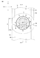
図2は、図1に示された規制リング10を拡大して示す斜視図である。図2に示すように、規制リング10は、本体11と、オス部12と、メス部13と、溶接部14と、を有している。図2に示す例では、規制リング10は、厚肉部15,16と、囲繞部17と、をさらに有している。
FIG. 2 is an enlarged perspective view of the
本体11は、トーション部2の周方向Yに延びる帯状に形成されている。オス部(第1係止部)12は、本体11の一端11Aに形成されている。メス部(第2係止部)13は、本体11の他端11Bに形成され、オス部12に係止している。溶接部14は、オス部12及びメス部13と同種の金属材料から略円形に形成され、オス部12及びメス部13を溶接している。
The
厚肉部15,16は、規制リング10の他の部位よりも0.5mm以上厚肉に形成されている。厚肉部15は、オス部12及びメス部13を規制リング10の幅方向に横断する帯状に形成されている。規制リングの幅方向は、トーション部2の軸方向X及び車両の車幅方向と一致する。厚肉部16は、周方向Yにおいて厚肉部15の180°反対側に形成されている。
The
囲繞部17は、本体11の一端11A及び他端11Bに跨って設けられ、溶接部14の周りを囲っている。囲繞部17において、規制リング10の外周面10A及び側面10Cは、溶接部14から露出している。囲繞部17は、本体11の一端11Aに設けられたオス側囲繞部17Mと、他端11Bに設けられたメス側囲繞部17Fと、を含んでいる。オス側囲繞部17Mは、オス部12と一体的に形成されている。メス側囲繞部17Fは、メス部13と一体的に形成されている。
The surrounding
オス側囲繞部17Mとメス側囲繞部17Fとは、トーション部2の軸方向Xにおいて面一に形成されている。囲繞部17では、溶接部14が排除されている。つまり、オス部12及びメス部13において、オス側囲繞部17M及びメス側囲繞部17Fで構成された側面10Cは、平坦に形成されている。規制リング10の側面10Cは、トーション部2に分力荷重が入力されたとき、ブッシュBに当接する。
The male
図3は、規制リング10のオス部12及びメス部13を拡大して示す側面図である。図3に示すように、メス部13は、オス部12に向かって開口した凹状に形成されており、谷底部31と、一対の挟持部32,33と、を有している。谷底部31は、本体11の他端11Bにおいてメス部13の底を構成している。一対の挟持部32,33は、規制リング10の幅方向(軸方向X)に互いに間隔OPをあけて配置されている。
FIG. 3 is an enlarged side view showing the
一対の挟持部32,33は、谷底部31から周方向Yに遠ざかるに従い、軸方向Xに間隔OPが狭くなる。図3中の上から下に向かう方向が谷底部31から遠ざかる方向である。図3中の上から下に向かう方向を、本体11において一端11Aから他端11Bに向かう方向、或いは、本体11からメス部13に向かう方向と言い換えてもよい。一対の挟持部32,33の先端32D,33Dは、メス部13の他の部位よりも間隔OPが狭い隘路を構成している。
The distance OP between the pair of holding
オス部12は、メス部13に向かって突出した凸状に形成されており、頸部21と、膨張部22と、収縮部23と、案内部24,25と、を有している。頸部21は、本体11の一端11Aから延び、本体11よりも幅狭に形成されている。頸部21は、一対の挟持部32,33の先端32D,33Dの間に挿通されている。
The
膨張部22は、頸部21から遠ざかるに従い規制リング10の幅方向(軸方向X)に大きくなる。収縮部23は、頸部21から遠ざかるに従い規制リング10の幅方向に小さくなる。図3中の下から上に向かう方向が頸部21から遠ざかる方向である。図3中の下から上に向かう方向を、本体11において他端11Bから一端11Aに向かう方向、或いは、本体11からオス部12に向かう方向と言い換えてもよい。
The
図3に示す例では、収縮部23は、半円状に形成されている。膨張部22は、頸部21に連続する部位を除いて、半円状に形成されている。案内部(肩部)24,25は、規制リング10の幅方向において頸部21を挟んでその両側にそれぞれ設けられている。案内部24,25には、オス部12から本体11に向かうに従い頸部21に近づく傾斜面が形成されている。
In the example shown in FIG. 3, the contracted
溶接部14は、規制リング10の外周面10Aから見て少なくともオス部12の収縮部23及びメス部13の谷底部31の範囲を覆っている。図3に示す例では、溶接部14が、オス部12の収縮部23、膨張部22、頸部21、メス部13の谷底部31及び挟持部32,33の先端32D,33Dを覆っている。また、溶接部14は、規制リング10の外周面10Aから見て円形状を有している。
The welded
図4は、図3中のF4−F4線に沿う断面図である。図4に示すように、溶接部14は、規制リング10の外周面10Aから板厚方向Zに溶け込んでオス部12の収縮部23及びメス部13の谷底部31を一体化している。厚肉部15,16とは異なる部位における規制リング10の板厚をZtとする。溶接部14の高さZhは、規制リング10の板厚Ztの例えば1/2以下である。
FIG. 4 is a cross-sectional view taken along the line F4-F4 in FIG. As shown in FIG. 4, the welded
規制リング10の内周面10Bには、トーション部2の塗膜5よりも硬い凹凸パターン18が形成されており、凹凸パターン18が塗膜5と噛み合っている。凹凸パターン18は、例えばローレット加工によって形成できる。規制リング10が結合した結合部位2Bの塗膜5を、目玉部3E,4Eの塗膜5よりも厚膜に形成してもよい。塗膜5は、例えば粉体焼付塗装により形成できる。塗膜5の膜厚は、例えば塗装時間や塗装回数によって調整できる。
An
規制リング10は、例えばアルミやアルミ合金等の金属材料から形成され、トーション部2に後付けされる。トーション部2に結合される前の状態の規制リング10は、C字状に湾曲した帯状に形成されている。この状態の規制リング10は、図4に示す一対の挟持部32,33の間隔OPが一定であり、先端32D,33Dが隘路になっていない。
The
本実施形態のスタビライザ1を製造する製造方法は、準備工程と、かしめ工程と、溶接工程と、を備えている。準備工程では、規制リング10の本体11をトーション部2に巻き付けるように配置する。かしめ工程では、メス部13をオス部12に押し付けて、メス部13の挟持部32,33をオス部12の膨張部22に倣う形状に塑性変形させる。
The manufacturing method for manufacturing the stabilizer 1 of the present embodiment includes a preparatory step, a caulking step, and a welding step. In the preparatory step, the
メス部13をオス部12に押し付けると、一対の挟持部32,33が、案内部24,25の傾斜面に案内されて頸部21に向かって変形する。やがて、一対の挟持部32,33が、膨張部22に倣う形状に形成され、メス部13がオス部12に係止する。溶接工程では、オス部12及びメス部13を溶接して、図2及び図3に示す溶接部14を形成する。
When the
このとき、収縮部23と谷底部31との間には、図3に示すように、スプリングバックによって僅かな隙間が生じることがある。つまり、かしめ工程で形成された規制リング10では、収縮部23と谷底部31とが切断されており、収縮部23が規制リング10の結合力に寄与していない。
At this time, as shown in FIG. 3, a slight gap may be generated between the contracted
しかるに、本実施形態に係る製造方法は、かしめ工程の後に溶接工程を含んでいる。溶接工程では、図3及び図4に示すように、収縮部23と谷底部31とを一体化した溶接部14を形成する。溶接工程を経た規制リング10は、膨張部22と一対の挟持部32,33との係合に加えて、さらに収縮部23と谷底部31との係合を有している。
However, the manufacturing method according to the present embodiment includes a welding step after the caulking step. In the welding step, as shown in FIGS. 3 and 4, a welded
以下、溶接工程において種々の形状の溶接部14を形成した第1乃至第7実施例並びに第1及び第2比較例について、図5乃至図13を参照して説明する。第1乃至第7実施例並びに第1及び第2比較例はすべて、幅が14mm、板厚Ztが4.2mmの規制リング10に直径5mmの収縮部23を形成した点が共通している。図5乃至図8中に右上がり斜線で示した範囲は厚肉部15に相当し、板厚Ztよりも0.5mm以上厚肉に形成されている。
Hereinafter, the first to seventh examples and the first and second comparative examples in which the welded
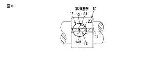
第1実施例は、図5に示すように、直径10mm、高さZhが2mmの溶接部14をオス部12の中央に形成した。溶接部14の中心14Xは厚肉部15に重なっている。
第2実施例は、図6に示すように、直径10mm、高さZhが2mmの溶接部14を第1実施例と比べて幅方向にずらして形成した。溶接部14の中心14Xは厚肉部15に重なっている。
第3実施例は、図7に示すように、直径10mm、高さZhが2mmの溶接部14を第1実施例と比べてオス部12の収縮部23側にずらして形成した。溶接部14の中心14Xは厚肉部15の範囲から外れている。
第4実施例は、図8に示すように、直径10mm、高さZhが2mmの溶接部14を第1実施例と比べてオス部12の膨張部22側にずらして形成した。溶接部14の中心14Xは厚肉部15の範囲から外れている。
In the first embodiment, as shown in FIG. 5, a welded
In the second embodiment, as shown in FIG. 6, the welded
As shown in FIG. 7, the third embodiment was formed by shifting the welded
In the fourth embodiment, as shown in FIG. 8, the welded
第5実施例は、図9に示すように、直径8mm、高さZhが2mmの溶接部14を形成した。溶接部14の高さZhは規制リング10の板厚Ztの1/2以下である。
第6実施例は、図10に示すように、直径8mm、高さZhが2mmの溶接部14を第5実施例と比べて幅方向にずらして形成した。溶接部14の高さZhは規制リング10の板厚Ztの1/2以下である。
第7実施例は、図11に示すように、直径7mm、高さZhが3mmの溶接部14を形成した。溶接部14の高さZhは規制リング10の板厚Ztの1/2を超えている。
第1比較例は、図12に示すように、直径5mmの溶接部14を形成した。
第2比較例は、溶接部14を形成しなかった。
In the fifth embodiment, as shown in FIG. 9, a welded
In the sixth embodiment, as shown in FIG. 10, the welded
In the seventh embodiment, as shown in FIG. 11, a welded
In the first comparative example, as shown in FIG. 12, a welded
In the second comparative example, the welded
図13は、第1乃至第7実施例並びに第1及び第2比較例について測定した規制リング10の結合力を示す図である。規制リング10が結合した結合部位2B及びその近傍を試験片として切り出し、ブッシュBと同様の形状の治具を規制リング10に押し当てて、規制リング10が破断した際の荷重を測定している。
FIG. 13 is a diagram showing the binding force of the
図13に示すように、結合部位2Bにおける塗膜5の膜厚が大きくなるほど、規制リング10の結合力は大きくなった。同じ膜厚で比べると、第1実施例>第2実施例>第3実施例>第4実施例>第5実施例>第6実施例>第7実施例>第1比較例>第2比較例の順に、規制リング10の結合力は大きくなった。
As shown in FIG. 13, the larger the film thickness of the
溶接部14の中心14Xが厚肉部15の範囲に重なっていた測定結果(第1及び第2実施例)と、溶接部14の中心14Xが厚肉部15の範囲から外れていた測定結果(第3及び第4実施例)とを比べると、溶接部14の中心14Xが厚肉部15の範囲から外れた規制リング10で結合力が下がる傾向があった。
The measurement result (first and second examples) in which the
さらに、溶接部14の中心14Xが厚肉部15の範囲から外れていた第3及び第4実施例を比べると、厚肉部15から収縮部23側にずらした第3実施例は、第1及び第2実施例とほとんど差異がなかった。一方で、厚肉部15から膨張部22側にずらした第4実施例は、第1乃至第3実施例よりも結合力が大きく下がっていた。収縮部23を覆う溶接部14が結合力に大きく寄与していることが分かる。
Further, comparing the third and fourth embodiments in which the
また、溶接部14の高さZhが規制リング10の板厚Ztの1/2以下であった測定結果(第5及び第6実施例)と、溶接部14の高さZhが規制リング10の板厚Ztの1/2を超えた測定結果(第7実施例)とを比べると、溶接部14の高さZhが規制リング10の板厚Ztの1/2を超えた規制リング10で結合力が下がる傾向があった。
Further, the measurement result (fifth and sixth examples) in which the height Zh of the welded
図14は、溶接部14の裏側で測定した溶接工程におけるトーション部2の表面温度の一例を示す図である。図14に示すように、溶接工程においてトーション部2及び規制リング10の温度が瞬間的に上昇する。その後、冷却された規制リング10は、収縮して結合部位2Bの塗膜5と噛み合う。
FIG. 14 is a diagram showing an example of the surface temperature of the
また、オス部12及びメス部13の内、溶接によって一体化されていない部位において、冷却された規制リング10の収縮により、オス部12とメス部13とが互いにさらに強固に係止される。トーション部2の表面温度は、例えば80℃以下であり、トーション部2のばね鋼の焼戻し温度や塗膜5の焼き付け温度と比べてはるかに低温である。
Further, in the
以上のように構成された本実施形態のスタビライザ1は、これまで結合力に寄与していなかった収縮部23及び谷底部31を溶接部14によって一体化している。本実施形態によれば、膨張部22と一対の挟持部32,33との係合に加えて、さらに収縮部23と谷底部31との係合を規制リング10の結合力に寄与するように構成できる。
In the stabilizer 1 of the present embodiment configured as described above, the contracted
その結果、規制リング10が大きな分力荷重に耐えられるようになり、トーション部2の軸方向Xの位置ずれをより確実に防止できる。また、これまで規制リング10を適用できなかった剛性の大きなスタビライザ1にも規制リング10を適用できるようになり、より広範な車種においてトーション部2の軸方向Xの位置ずれを防止できる。
As a result, the
仮に、トーション部2の軸方向Xの移動を阻止する目的で、トーション部2をブッシュBに完全に固定すると、トーション部2が回転運動できなくなってスタビライザ1のばね特性が変化してしまう。
仮に、スラスト荷重を加えてトーション部2それ自体が局部的に太径になるように塑性変形させると、規制リング10を後付けする場合と比べて、工数が大幅に増えてコストが増加する。車種によって規制リング10の有無や寸法を柔軟に変更することもできなくなる。
これに対し、本実施形態であれば、規制リング10の優れた長所を活かしつつ、トーション部2に対する規制リング10の結合力を向上させることができる。
If the
If a thrust load is applied to plastically deform the
On the other hand, in the present embodiment, it is possible to improve the binding force of the
溶接部14の高さZhは、板厚Ztの1/2以下が好適である。溶接部14の高さZhが板厚Ztの1/2以下であれば、溶接部14が十分な深さZdまで板厚方向Zに溶け込んでいるため、収縮部23と谷底部31とを強固に一体化できる。また、溶接部14の高さZhを、板厚Ztの1/2以下とすることで、規制リング10と他の部品との干渉を防ぐことができる。さらに、溶接部14の高さZhを指標とするため、溶接部14の溶け込み量を管理することが容易になり、溶接時の過度の入熱によって、スタビライザ1の塗膜に悪影響が生じることを効果的に防止できる。
The height Zh of the welded
本実施形態は、オス部12及びメス部13を横断する帯状の厚肉部15を有している。厚肉部15に重なるように溶接部14の中心14Xを配置すれば、厚肉部15を起点に広がる溶接部14でオス部12すべてを覆うように溶接部14を形成できる。収縮部23及び谷底部31に加え、さらにオス部12とメス部13との境界すべてを覆う溶接部14を形成できるため、規制リング10を強固に結合できる。
The present embodiment has a strip-shaped
本実施形態は、溶接部14が排除された囲繞部17を有している。囲繞部17は、オス部12及びメス部13に跨って形成され、オス部12及びメス部13において側面10Cが面一になるように形成されている。本実施形態によれば、ブッシュBに側面10Cが当接するとき、オス部12及びメス部13に過大な荷重が集中しないように側面10Cを平坦に構成できる。また、囲繞部17を有することにより、溶接時の入熱による影響を緩和でき、規制リング10において溶接部14以外の組織変化を防止できる。
The present embodiment has a surrounding
本発明のいくつかの実施形態を説明したが、これらの実施形態は、例として提示したものであり、発明の範囲を限定することは意図していない。これら新規な実施形態は、その他の様々な形態で実施されることが可能であり、発明の要旨を逸脱しない範囲で、種々の省略、置き換え、変更を行うことができる。これら実施形態やその変形例は、発明の範囲や要旨に含まれるとともに、特許請求の範囲に記載された発明とその均等の範囲に含まれる。 Although some embodiments of the present invention have been described, these embodiments are presented as examples and are not intended to limit the scope of the invention. These novel embodiments can be implemented in various other embodiments, and various omissions, replacements, and changes can be made without departing from the gist of the invention. These embodiments and modifications thereof are included in the scope and gist of the invention, and are also included in the scope of the invention described in the claims and the equivalent scope thereof.
1…スタビライザ、2…トーション部、2B…結合部位(ブッシュに隣接する部位、規制リングが結合した部位)、2L,2R…トーション部の両端、3,4…アーム部、3E,4E…目玉部、5…塗膜、10…規制リング、10A…規制リングの外周面、10B…規制リングの内周面、11…本体、11A…本体の一端、11B…本体の他端、12…オス部、13…メス部、14…溶接部、15…厚肉部、17…囲繞部、17M…オス側囲繞部、17F…メス側囲繞部、18…凹凸パターン、21…頸部、22…膨張部、23…収縮部、24,25…案内部、31…谷底部、32,33…挟持部、32D,33D…挟持部の先端、B…ブッシュ、IS…サスペンション装置、OP…一対の挟持部の間隔、W…車輪、X…トーション部の軸方向、Z…規制リングの板厚方向、Zh…溶接部の高さ、Zt…規制リングの板厚。
1 ... Stabilizer, 2 ... Torsion part, 2B ... Joint part (part adjacent to bush, part where regulation ring is connected), 2L, 2R ... Both ends of torsion part, 3,4 ... Arm part, 3E, 4E ...
Claims (9)
前記トーション部の両端から左右の車輪に向かってそれぞれ延び、サスペンション装置に取り付けられる一対のアーム部と、
前記ブッシュに隣接する部位において前記トーション部に結合された規制リングと、を備えた車両用のスタビライザであって、
前記規制リングは、
帯状に形成された本体と、
前記本体の他端に位置した谷底部と、前記トーション部の軸方向に互いに間隔をあけて配置されており該谷底部から遠ざかるに従い該間隔が狭くなる一対の挟持部と、を有したメス部と、
前記本体の一端から延びており前記一対の挟持部の先端の間に挿通された頸部と、該頸部から遠ざかるに従い前記トーション部の軸方向に大きくなる膨張部と、該頸部から遠ざかるに従い該トーション部の軸方向に小さくなる収縮部と、を有したオス部と、
前記オス部及び前記メス部を前記規制リングの幅方向に横断する帯状の厚肉部と、
前記オス部及び前記メス部を溶接した溶接部と、を有し、
前記溶接部は、前記規制リングの外周面から見て少なくとも前記収縮部及び前記谷底部の範囲と前記厚肉部の一部を覆い、前記収縮部と前記谷底部との間の隙間を覆いかつ前記外周面から前記規制リングの板厚方向に溶け込んで該収縮部及び該谷底部を一体化していることを特徴とするスタビライザ。 A torsion part that is hung from the car body via a tubular bush,
A pair of arm portions extending from both ends of the torsion portion toward the left and right wheels and attached to the suspension device,
A stabilizer for a vehicle provided with a regulation ring coupled to the torsion portion at a portion adjacent to the bush.
The regulation ring
The main body formed in a band shape and
A female portion having a valley bottom located at the other end of the main body and a pair of holding portions that are arranged at intervals in the axial direction of the torsion portion and the spacing becomes narrower as the distance from the valley bottom increases. When,
A neck extending from one end of the main body and inserted between the tips of the pair of holding portions, an expanding portion that increases in the axial direction of the torsion portion as the distance from the neck increases, and an expanding portion that increases in the axial direction as the distance from the neck increases. A male portion having a contraction portion that becomes smaller in the axial direction of the torsion portion, and a male portion.
A strip-shaped thick portion that crosses the male portion and the female portion in the width direction of the regulation ring, and
It has a welded portion obtained by welding the male portion and the female portion.
The welded portion covers at least the range of the contracted portion and the valley bottom portion and a part of the thick wall portion when viewed from the outer peripheral surface of the regulation ring, and covers the gap between the contracted portion and the valley bottom portion. A stabilizer characterized in that the contracted portion and the valley bottom portion are integrated by melting from the outer peripheral surface in the plate thickness direction of the regulation ring.
前記溶接部の中心が、前記外周面から見て前記厚肉部に重なっていることを特徴とする請求項1乃至3のいずれか一項に記載のスタビライザ。 The thick portion of the regulation ring is formed to be thicker than the other parts of the regulation ring .
The center of the weld, the stabilizer according to any one of claims 1 to 3, characterized in that overlaps the thick portion as viewed from the outer peripheral surface.
前記規制リングが結合した部位の塗膜は、前記アーム部の先端に形成された目玉部の塗膜よりも厚膜に形成され、
前記規制リングは、前記塗膜よりも硬い凹凸パターンが形成された内周面をさらに有していることを特徴とする請求項1乃至4のいずれか一項に記載のスタビライザ。 The torsion portion and the pair of arm portions are covered with a coating film.
The coating film at the portion where the regulation ring is bonded is formed to be a thicker film than the coating film at the eyeball portion formed at the tip of the arm portion.
The stabilizer according to any one of claims 1 to 4, wherein the regulating ring further has an inner peripheral surface on which an uneven pattern harder than the coating film is formed.
前記囲繞部は、前記メス部と一体的に形成されたメス側囲繞部と、前記オス部と一体的に形成されたオス側囲繞部と、を含み、
前記メス側囲繞部と前記オス側囲繞部とは、前記トーション部の軸方向において面一に形成されていることを特徴とする請求項1乃至5のいずれか一項に記載のスタビライザ。 The regulation ring further has a surrounding portion that surrounds the welded portion and exposes the outer peripheral surface from the welded portion.
The surrounding portion includes a female-side surrounding portion integrally formed with the female portion and a male-side surrounding portion integrally formed with the male portion.
The stabilizer according to any one of claims 1 to 5, wherein the female side surrounding portion and the male side surrounding portion are formed flush with each other in the axial direction of the torsion portion.
前記トーション部の両端から左右の車輪に向かってそれぞれ延び、サスペンション装置に取り付けられる一対のアーム部と、
前記ブッシュに隣接する部位において前記トーション部に結合された規制リングと、を備えた車両用のスタビライザの製造方法であって、
前記規制リングは、
帯状に形成された本体と、
前記本体の他端に位置した谷底部と、前記トーション部の軸方向に互いに間隔をあけて配置された一対の挟持部と、を有したメス部と、
前記本体の一端から延びた頸部と、該頸部から遠ざかるに従い前記トーション部の軸方向に大きくなる膨張部と、該頸部から遠ざかるに従い該トーション部の軸方向に小さくなる収縮部と、を有したオス部と、を有しており、
前記本体を前記トーション部に巻き付けるように配置する準備工程と、
前記メス部を前記オス部に押し付けて、前記一対の挟持部を前記膨張部に倣う形状に塑性変形させかつ前記オス部及び前記メス部を前記規制リングの幅方向に横断する帯状の厚肉部を形成するかしめ工程と、
前記規制リングの外周面から見て少なくとも前記収縮部及び前記谷底部の範囲と前記厚肉部の一部を覆うように溶接し、前記収縮部と前記谷底部との間の隙間を覆いかつ前記外周面から前記規制リングの板厚方向に溶け込んで該収縮部及び該谷底部を一体化した溶接部を形成する溶接工程と、を備えたことを特徴とするスタビライザの製造方法。 A torsion part that is hung from the car body via a tubular bush,
A pair of arm portions extending from both ends of the torsion portion toward the left and right wheels and attached to the suspension device,
A method for manufacturing a stabilizer for a vehicle, comprising a regulation ring coupled to the torsion portion at a portion adjacent to the bush.
The regulation ring
The main body formed in a band shape and
A female portion having a valley bottom portion located at the other end of the main body and a pair of holding portions arranged at intervals in the axial direction of the torsion portion.
A neck extending from one end of the main body, an expanding portion that increases in the axial direction of the torsion portion as it moves away from the neck, and a contracting portion that decreases in the axial direction of the torsion portion as it moves away from the neck. Has a male part and has
A preparatory step of arranging the main body so as to be wound around the torsion portion, and
The female portion is pressed against the male portion to plastically deform the pair of sandwiching portions into a shape that resembles the expansion portion, and the male portion and the female portion cross the male portion and the female portion in the width direction of the regulation ring. The caulking process to form
Welding is performed so as to cover at least the range of the contracted portion and the valley bottom portion and a part of the thick wall portion when viewed from the outer peripheral surface of the regulating ring, and cover the gap between the contracted portion and the valley bottom portion. A method for manufacturing a stabilizer, which comprises a welding step of forming a welded portion in which the contracted portion and the valley bottom portion are integrated by melting from the outer peripheral surface in the plate thickness direction of the regulation ring.
前記溶接工程において、溶接された前記規制リングの温度が瞬間的に上昇し、冷却された前記規制リングが収縮して前記塗膜と噛み合うことを特徴とする請求項7に記載のスタビライザの製造方法。 The torsion portion is covered with a coating film, and the torsion portion is covered with a coating film.
The method for manufacturing a stabilizer according to claim 7, wherein in the welding step, the temperature of the welded regulation ring rises momentarily, and the cooled regulation ring contracts and meshes with the coating film. ..
Priority Applications (9)
| Application Number | Priority Date | Filing Date | Title |
|---|---|---|---|
| JP2017051335A JP6808549B2 (en) | 2017-03-16 | 2017-03-16 | Stabilizers for vehicles and methods for manufacturing the stabilizers |
| HUE18766767A HUE057580T2 (en) | 2017-03-16 | 2018-02-16 | Vehicle stabilizer and method for manufacturing said stabilizer |
| PCT/JP2018/005521 WO2018168327A1 (en) | 2017-03-16 | 2018-02-16 | Vehicle stabilizer and method for manufacturing said stabilizer |
| PL18766767T PL3597459T3 (en) | 2017-03-16 | 2018-02-16 | Vehicle stabilizer and method for manufacturing said stabilizer |
| CN201880017061.5A CN110392639B (en) | 2017-03-16 | 2018-02-16 | Stabilizer for vehicle and method for manufacturing the same |
| KR1020197029939A KR102290846B1 (en) | 2017-03-16 | 2018-02-16 | Stabilizer for vehicle and method for manufacturing the stabilizer |
| EP18766767.0A EP3597459B1 (en) | 2017-03-16 | 2018-02-16 | Vehicle stabilizer and method for manufacturing said stabilizer |
| ES18766767T ES2907030T3 (en) | 2017-03-16 | 2018-02-16 | Stabilizer for vehicles and manufacturing process of said stabilizer |
| US16/571,483 US11161385B2 (en) | 2017-03-16 | 2019-09-16 | Vehicle stabilizer and method of manufacturing the same |
Applications Claiming Priority (1)
| Application Number | Priority Date | Filing Date | Title |
|---|---|---|---|
| JP2017051335A JP6808549B2 (en) | 2017-03-16 | 2017-03-16 | Stabilizers for vehicles and methods for manufacturing the stabilizers |
Publications (2)
| Publication Number | Publication Date |
|---|---|
| JP2018154180A JP2018154180A (en) | 2018-10-04 |
| JP6808549B2 true JP6808549B2 (en) | 2021-01-06 |
Family
ID=63522062
Family Applications (1)
| Application Number | Title | Priority Date | Filing Date |
|---|---|---|---|
| JP2017051335A Active JP6808549B2 (en) | 2017-03-16 | 2017-03-16 | Stabilizers for vehicles and methods for manufacturing the stabilizers |
Country Status (9)
| Country | Link |
|---|---|
| US (1) | US11161385B2 (en) |
| EP (1) | EP3597459B1 (en) |
| JP (1) | JP6808549B2 (en) |
| KR (1) | KR102290846B1 (en) |
| CN (1) | CN110392639B (en) |
| ES (1) | ES2907030T3 (en) |
| HU (1) | HUE057580T2 (en) |
| PL (1) | PL3597459T3 (en) |
| WO (1) | WO2018168327A1 (en) |
Family Cites Families (18)
| Publication number | Priority date | Publication date | Assignee | Title |
|---|---|---|---|---|
| US2283918A (en) * | 1940-05-02 | 1942-05-26 | Cleveland Graphite Bronze Co | Method of making bushings |
| JPS60145639U (en) * | 1984-03-09 | 1985-09-27 | 豊生ブレ−キ工業株式会社 | engine mount assembly |
| US4944523A (en) * | 1989-03-03 | 1990-07-31 | Illinois Tool Works | End link for stabilizer bar |
| JPH02168005A (en) * | 1989-11-04 | 1990-06-28 | Kato Hatsujo Kaisha Ltd | Manufacture of clamp made of shape memory alloy |
| US5185908A (en) * | 1991-11-18 | 1993-02-16 | Hans Oetiker Ag Maschinen- Und Apparatefabrik | Method for connecting two parts along abutting edges and connection obtained thereby |
| JPH11210713A (en) * | 1998-01-26 | 1999-08-03 | Orihashi Seisakusho:Kk | Slippage prevention fixing ring |
| EP1071571B1 (en) * | 1998-04-23 | 2004-10-20 | Nhk Spring Co.Ltd. | Retaining arrangement for a rod member |
| JP3963593B2 (en) * | 1998-04-23 | 2007-08-22 | 横浜機工株式会社 | Bar material slip prevention structure |
| FR2790213B1 (en) * | 1999-02-26 | 2001-05-18 | Caillau Ets | SHRINK RING, MANUFACTURING METHOD, AND MANUFACTURING INSTALLATION |
| DE10018776C1 (en) * | 2000-04-15 | 2001-07-26 | Porsche Ag | Vehicle wheel suspension stabilizer bearing unit includes elastic bearing element which is mounted on stabilizer by inner shell with locking elements |
| JP4323358B2 (en) * | 2004-03-26 | 2009-09-02 | 三菱製鋼株式会社 | Stabilizer anti-slip device |
| US7290322B2 (en) * | 2004-09-01 | 2007-11-06 | Automotive Components Holdings, Llc | Method of crimping a ring shaped stop within an annular groove of a stabilizer bar |
| US20070074970A1 (en) * | 2005-09-20 | 2007-04-05 | Cp Technologies, Inc. | Device and method of manufacturing sputtering targets |
| JP4391490B2 (en) * | 2006-04-10 | 2009-12-24 | 日産自動車株式会社 | Vehicle stabilizer |
| DE102010044798A1 (en) * | 2010-09-09 | 2012-03-15 | Benteler Automobiltechnik Gmbh | Process for the preparation of a stabilizer and stabilizer |
| CN202782566U (en) * | 2012-09-11 | 2013-03-13 | 日本发条株式会社 | Limiting ring blank material and stable rod with limiting ring |
| CN103660841B (en) * | 2012-09-11 | 2015-10-14 | 日本发条株式会社 | To the method for stabilizer rod mounting limit circle and the stabilizer rod with limit coil |
| JP6343153B2 (en) * | 2014-02-18 | 2018-06-13 | 日本発條株式会社 | Mounting structure between bar and semi-finished product of movement restriction member |
-
2017
- 2017-03-16 JP JP2017051335A patent/JP6808549B2/en active Active
-
2018
- 2018-02-16 WO PCT/JP2018/005521 patent/WO2018168327A1/en unknown
- 2018-02-16 CN CN201880017061.5A patent/CN110392639B/en active Active
- 2018-02-16 PL PL18766767T patent/PL3597459T3/en unknown
- 2018-02-16 EP EP18766767.0A patent/EP3597459B1/en active Active
- 2018-02-16 HU HUE18766767A patent/HUE057580T2/en unknown
- 2018-02-16 ES ES18766767T patent/ES2907030T3/en active Active
- 2018-02-16 KR KR1020197029939A patent/KR102290846B1/en active IP Right Grant
-
2019
- 2019-09-16 US US16/571,483 patent/US11161385B2/en active Active
Also Published As
| Publication number | Publication date |
|---|---|
| CN110392639A (en) | 2019-10-29 |
| JP2018154180A (en) | 2018-10-04 |
| EP3597459A1 (en) | 2020-01-22 |
| EP3597459B1 (en) | 2022-02-02 |
| US20200009937A1 (en) | 2020-01-09 |
| KR102290846B1 (en) | 2021-08-17 |
| EP3597459A4 (en) | 2020-12-30 |
| CN110392639B (en) | 2023-02-21 |
| KR20190126863A (en) | 2019-11-12 |
| WO2018168327A1 (en) | 2018-09-20 |
| US11161385B2 (en) | 2021-11-02 |
| HUE057580T2 (en) | 2022-05-28 |
| PL3597459T3 (en) | 2022-06-20 |
| ES2907030T3 (en) | 2022-04-21 |
Similar Documents
| Publication | Publication Date | Title |
|---|---|---|
| US10081044B2 (en) | Method for producing a chassis link | |
| JP5398192B2 (en) | Stabilizer device and manufacturing method thereof | |
| US10518596B2 (en) | Joint | |
| CN106312450B (en) | For obtaining the method and cantilever of automotive suspension arm | |
| EP3505375B1 (en) | Stabilizer link and method for manufacturing stabilizer link | |
| JP4663752B2 (en) | Stabilizer device and manufacturing method thereof | |
| EP3321026B1 (en) | Manufacturing method for a bent member | |
| US20110210528A1 (en) | Stabilizing strut for a chassis of a vehicle | |
| US9561699B2 (en) | Chassis link for a motor vehicle | |
| JP2011162188A (en) | Transverse link and method of manufacturing transverse link | |
| CN108688430B (en) | Stabilizer link for a vehicle suspension | |
| US20170305223A1 (en) | Structural component for a motor vehicle | |
| US20180178853A1 (en) | Axle or chassis component for a motor vehicle | |
| US20200317013A1 (en) | Spring control arm | |
| US9441512B1 (en) | Muffler shell body with integral aerodynamic shield | |
| KR102119176B1 (en) | Control arm | |
| JP6808549B2 (en) | Stabilizers for vehicles and methods for manufacturing the stabilizers | |
| CN110641239A (en) | Suspension member for vehicle | |
| CN104438467B (en) | A kind of Non-carrying type frame lateral bending school shape frock and straightening method | |
| CN111070987B (en) | Damper strut consisting of two half-shells | |
| JP6468043B2 (en) | Torsion beam, torsion beam assembly and torsion beam suspension device | |
| JP6736208B2 (en) | Torsion beam | |
| JP2021151823A (en) | Railway vehicle truck frame and manufacturing method for the same | |
| JP5342225B2 (en) | Axle case structure | |
| EP3995331A1 (en) | Stabilizer |
Legal Events
| Date | Code | Title | Description |
|---|---|---|---|
| A621 | Written request for application examination |
Free format text: JAPANESE INTERMEDIATE CODE: A621 Effective date: 20190807 |
|
| A131 | Notification of reasons for refusal |
Free format text: JAPANESE INTERMEDIATE CODE: A131 Effective date: 20200428 |
|
| A521 | Request for written amendment filed |
Free format text: JAPANESE INTERMEDIATE CODE: A523 Effective date: 20200626 |
|
| A02 | Decision of refusal |
Free format text: JAPANESE INTERMEDIATE CODE: A02 Effective date: 20200804 |
|
| A521 | Request for written amendment filed |
Free format text: JAPANESE INTERMEDIATE CODE: A523 Effective date: 20201023 |
|
| C60 | Trial request (containing other claim documents, opposition documents) |
Free format text: JAPANESE INTERMEDIATE CODE: C60 Effective date: 20201023 |
|
| A911 | Transfer to examiner for re-examination before appeal (zenchi) |
Free format text: JAPANESE INTERMEDIATE CODE: A911 Effective date: 20201105 |
|
| C21 | Notice of transfer of a case for reconsideration by examiners before appeal proceedings |
Free format text: JAPANESE INTERMEDIATE CODE: C21 Effective date: 20201110 |
|
| TRDD | Decision of grant or rejection written | ||
| A01 | Written decision to grant a patent or to grant a registration (utility model) |
Free format text: JAPANESE INTERMEDIATE CODE: A01 Effective date: 20201201 |
|
| A61 | First payment of annual fees (during grant procedure) |
Free format text: JAPANESE INTERMEDIATE CODE: A61 Effective date: 20201209 |
|
| R150 | Certificate of patent or registration of utility model |
Ref document number: 6808549 Country of ref document: JP Free format text: JAPANESE INTERMEDIATE CODE: R150 |
|
| R250 | Receipt of annual fees |
Free format text: JAPANESE INTERMEDIATE CODE: R250 |