JP6805960B2 - Sanitary goods manufacturing equipment - Google Patents
Sanitary goods manufacturing equipment Download PDFInfo
- Publication number
- JP6805960B2 JP6805960B2 JP2017097544A JP2017097544A JP6805960B2 JP 6805960 B2 JP6805960 B2 JP 6805960B2 JP 2017097544 A JP2017097544 A JP 2017097544A JP 2017097544 A JP2017097544 A JP 2017097544A JP 6805960 B2 JP6805960 B2 JP 6805960B2
- Authority
- JP
- Japan
- Prior art keywords
- coating
- base paper
- paper
- roll
- width direction
- Prior art date
- Legal status (The legal status is an assumption and is not a legal conclusion. Google has not performed a legal analysis and makes no representation as to the accuracy of the status listed.)
- Active
Links
- 238000004519 manufacturing process Methods 0.000 title claims description 59
- 238000000576 coating method Methods 0.000 claims description 321
- 239000011248 coating agent Substances 0.000 claims description 291
- 239000000126 substance Substances 0.000 claims description 101
- 238000004049 embossing Methods 0.000 claims description 68
- 239000007788 liquid Substances 0.000 claims description 32
- 239000003795 chemical substances by application Substances 0.000 claims description 29
- 239000004744 fabric Substances 0.000 claims description 13
- 239000000123 paper Substances 0.000 description 380
- 238000000034 method Methods 0.000 description 47
- 238000004804 winding Methods 0.000 description 35
- 239000003814 drug Substances 0.000 description 34
- 238000005520 cutting process Methods 0.000 description 31
- 238000009736 wetting Methods 0.000 description 31
- 229940079593 drug Drugs 0.000 description 28
- 238000010030 laminating Methods 0.000 description 24
- 230000037303 wrinkles Effects 0.000 description 17
- 238000001035 drying Methods 0.000 description 14
- 239000010410 layer Substances 0.000 description 14
- 239000000047 product Substances 0.000 description 14
- 239000013043 chemical agent Substances 0.000 description 13
- 230000008569 process Effects 0.000 description 13
- 239000000835 fiber Substances 0.000 description 11
- 238000004806 packaging method and process Methods 0.000 description 10
- 230000004048 modification Effects 0.000 description 9
- 238000012986 modification Methods 0.000 description 9
- 239000002994 raw material Substances 0.000 description 9
- 238000011144 upstream manufacturing Methods 0.000 description 8
- XLYOFNOQVPJJNP-UHFFFAOYSA-N water Substances O XLYOFNOQVPJJNP-UHFFFAOYSA-N 0.000 description 8
- 230000009471 action Effects 0.000 description 7
- 230000000694 effects Effects 0.000 description 7
- 230000002093 peripheral effect Effects 0.000 description 7
- 239000002002 slurry Substances 0.000 description 7
- 239000000243 solution Substances 0.000 description 7
- 230000008859 change Effects 0.000 description 4
- 238000010586 diagram Methods 0.000 description 4
- 230000001965 increasing effect Effects 0.000 description 4
- 230000007246 mechanism Effects 0.000 description 4
- 239000004909 Moisturizer Substances 0.000 description 3
- 238000003490 calendering Methods 0.000 description 3
- 230000006870 function Effects 0.000 description 3
- 238000002347 injection Methods 0.000 description 3
- 239000007924 injection Substances 0.000 description 3
- 230000001333 moisturizer Effects 0.000 description 3
- PEDCQBHIVMGVHV-UHFFFAOYSA-N Glycerine Chemical compound OCC(O)CO PEDCQBHIVMGVHV-UHFFFAOYSA-N 0.000 description 2
- 239000002250 absorbent Substances 0.000 description 2
- 239000002386 air freshener Substances 0.000 description 2
- 230000006866 deterioration Effects 0.000 description 2
- 230000005484 gravity Effects 0.000 description 2
- 239000000463 material Substances 0.000 description 2
- 239000004745 nonwoven fabric Substances 0.000 description 2
- 230000035515 penetration Effects 0.000 description 2
- 239000012466 permeate Substances 0.000 description 2
- 230000000704 physical effect Effects 0.000 description 2
- 230000036544 posture Effects 0.000 description 2
- 238000003825 pressing Methods 0.000 description 2
- FBPFZTCFMRRESA-FSIIMWSLSA-N D-Glucitol Natural products OC[C@H](O)[C@H](O)[C@@H](O)[C@H](O)CO FBPFZTCFMRRESA-FSIIMWSLSA-N 0.000 description 1
- FBPFZTCFMRRESA-JGWLITMVSA-N D-glucitol Chemical compound OC[C@H](O)[C@@H](O)[C@H](O)[C@H](O)CO FBPFZTCFMRRESA-JGWLITMVSA-N 0.000 description 1
- 235000002597 Solanum melongena Nutrition 0.000 description 1
- 244000061458 Solanum melongena Species 0.000 description 1
- 230000002708 enhancing effect Effects 0.000 description 1
- 239000011094 fiberboard Substances 0.000 description 1
- 239000012530 fluid Substances 0.000 description 1
- 235000011187 glycerol Nutrition 0.000 description 1
- 238000007756 gravure coating Methods 0.000 description 1
- 229910052739 hydrogen Inorganic materials 0.000 description 1
- 239000001257 hydrogen Substances 0.000 description 1
- 230000006872 improvement Effects 0.000 description 1
- 239000004615 ingredient Substances 0.000 description 1
- 239000002184 metal Substances 0.000 description 1
- 229910052751 metal Inorganic materials 0.000 description 1
- 230000003020 moisturizing effect Effects 0.000 description 1
- 239000000049 pigment Substances 0.000 description 1
- 230000009467 reduction Effects 0.000 description 1
- 239000011347 resin Substances 0.000 description 1
- 229920005989 resin Polymers 0.000 description 1
- 230000004043 responsiveness Effects 0.000 description 1
- 230000000717 retained effect Effects 0.000 description 1
- 239000011265 semifinished product Substances 0.000 description 1
- 230000035807 sensation Effects 0.000 description 1
- 238000000926 separation method Methods 0.000 description 1
- 239000002356 single layer Substances 0.000 description 1
- 239000000600 sorbitol Substances 0.000 description 1
- 239000007921 spray Substances 0.000 description 1
- 238000005507 spraying Methods 0.000 description 1
Images


Description
本件は、液剤を塗る塗工装置および塗工方法、ならびに、この塗工装置および塗工方法により液剤が塗布された抄造体から衛生用品を製造する装置および方法に関する。 The present invention relates to a coating device and a coating method for applying a liquid agent, and an apparatus and a method for producing a sanitary product from a paper machine coated with the liquid agent by the coating device and the coating method.
ティシュペーパやペーパタオルといった衛生用品を製造する工程では、搬送される帯状の原紙に保湿剤や芳香剤などの液剤を塗布することがある。従来、このような原紙に液剤を塗る手法の一つとして、グラビア方式によるものが知られている(たとえば特許文献1参照)。 In the process of manufacturing sanitary products such as tissue paper and paper towels, a liquid agent such as a moisturizer or an air freshener may be applied to the strip-shaped base paper to be transported. Conventionally, a gravure method has been known as one of the methods for applying a liquid agent to such a base paper (see, for example, Patent Document 1).
グラビア方式は、版目(凹部)が周面に刻設されたグラビアロールと、このグラビアロールに対向して配置されたバックアップロールとの間に被塗布物を通し、グラビアロールから被塗布物に液剤を転写する方式である。一般に、このようなグラビア方式の塗工では、グラビアロールの回転速度を変更することで、被塗布物に対する液剤の塗布量(塗布膜の厚み)が変更される。 In the gravure method, the object to be coated is passed between the gravure roll in which the plate (recess) is engraved on the peripheral surface and the backup roll arranged so as to face the gravure roll, and the gravure roll is changed to the object to be coated. This is a method of transferring a liquid agent. Generally, in such a gravure method coating, the amount of the liquid agent applied to the object to be coated (thickness of the coating film) is changed by changing the rotation speed of the gravure roll.
しかしながら、塗布量はグラビアロールの回転速度に対してリニアに変化しないことがある。このため、グラビア方式の塗工法では塗布量の調整が難しいという課題がある。また、グラビアロールとバックアップロールとが被塗布物を挟んで対向配置されるため、装置の省スペース化が難しいという課題もある。 However, the coating amount may not change linearly with the rotation speed of the gravure roll. Therefore, there is a problem that it is difficult to adjust the coating amount in the gravure coating method. Further, since the gravure roll and the backup roll are arranged so as to face each other with the object to be coated interposed therebetween, there is also a problem that it is difficult to save space in the apparatus.
本件は、上記のような課題に鑑みて創案されたものであり、塗布量の調整を容易にするとともに省スペース化を実現することを目的の一つとする。 This case was devised in view of the above-mentioned problems, and one of the purposes is to facilitate the adjustment of the coating amount and to realize space saving.
(1)ここで開示する塗工装置は、被塗布物に接するように設けられた塗工部を有し、親液性をもつとともに布状に形成された塗布部材と、前記塗布部材に液剤を供給する供給装置とを備えている。
(2)ここで開示する衛生用品の製造装置は、張架された状態で搬送される帯状の抄造体から所定の幅方向寸法をなす衛生用品を製造する装置であって、前記所定の幅方向寸法に裁断された前記抄造体に薬液を塗布する塗布部を備え、前記塗布部が、前記塗工装置であって、前記抄造体に前記液剤としての前記薬液を塗布する。
(3)ここで開示する塗工方法は、被塗布物に接するように設けられた塗工部を有する塗布部材に液剤を供給する供給工程と、前記供給工程で供給された前記液剤を前記塗布部材に浸透させる浸透工程と、前記浸透工程で浸透した前記液剤を前記塗工部から染み出させて前記被塗布物に塗布する塗工工程と、を備えている。
(4)ここで開示する衛生用品の製造方法は、シートに薬液を塗布する塗布工程を備え、前記塗布工程では、前記塗工方法により、前記被塗布物としての前記シートに前記液剤としての前記薬液を塗布し、前記シートを巻き取らずに積層し、折り畳む。
(1) The coating device disclosed here has a coating portion provided so as to be in contact with the object to be coated, has a liquid-like property and is formed in a cloth shape, and a liquid agent on the coating member. It is equipped with a supply device that supplies.
(2) The sanitary goods manufacturing apparatus disclosed here is an apparatus for manufacturing sanitary goods having a predetermined width direction dimension from a strip-shaped paper machine transported in a stretched state, and is described in the predetermined width direction. A coating portion for applying a chemical solution to the paper machine cut to a size is provided, and the coating portion is the coating device, and the chemical solution as the liquid agent is applied to the paper machine.
(3) The coating method disclosed here includes a supply step of supplying a liquid agent to a coating member having a coating portion provided so as to be in contact with an object to be coated, and the coating of the liquid agent supplied in the supply step. It includes a permeation step of permeating the member and a coating step of exuding the liquid agent permeated in the permeation step from the coating portion and applying the liquid agent to the object to be coated.
(4) The method for manufacturing a sanitary product disclosed here includes a coating step of applying a chemical solution to a sheet, and in the coating step, the coating method is used to apply the chemical solution to the sheet as the object to be coated. A chemical solution is applied, and the sheets are laminated without being wound up and folded.
本件によれば、塗布量の調整を容易にすることができるとともに、省スペース化を実現することができる。 According to this case, it is possible to easily adjust the coating amount and to save space.
本件を実施するための形態を説明する。下記の実施形態はあくまでも例示に過ぎず、実施形態で明示しない種々の変形や技術の適用を排除する意図はない。この実施形態の各構成は、その趣旨を逸脱しない範囲で種々変形して実施することができる。また、必要に応じて取捨選択することができ、適宜組み合わせることもできる。 A mode for carrying out this case will be described. The following embodiments are merely examples, and there is no intention of excluding various modifications and applications of techniques not specified in the embodiments. Each configuration of this embodiment can be variously modified and implemented without departing from the gist thereof. In addition, it can be selected as needed and can be combined as appropriate.
[I.一実施形態]
本実施形態の塗工装置および塗工方法は、衛生用品を製造する製造装置および製造方法に組み込まれている。この製造装置および製造方法によって製造される衛生用品は、抄造体である。
抄造体とは、繊維を用いて抄造された物である。この抄造体としては、パルプ繊維から抄造される紙や樹脂繊維から抄造される不織布が挙げられる。たとえば、抄造体には、ティシュペーパやペーパタオルなどの衛生用紙のほか衛生用不織布といった衛生用品が含まれる。
[I. One Embodiment]
The coating apparatus and coating method of the present embodiment are incorporated into a manufacturing apparatus and manufacturing method for manufacturing sanitary products. The sanitary goods manufactured by this manufacturing apparatus and manufacturing method are papermaking bodies.
A paper machine is a product made using fibers. Examples of this paper machine include paper made from pulp fibers and non-woven fabric made from resin fibers. For example, papermaking includes sanitary papers such as tissue paper and paper towels, as well as sanitary products such as sanitary non-woven fabrics.
以下の実施形態では、上記した衛生用品の一例として、搬送される帯状の原紙(抄紙)から製造される枚葉状(シート状)のティシュペーパを挙げる。
なお、下記の実施形態では、原紙が搬送される方向(以下「搬送方向」と略称する)を基準に上流および下流を定める。また、原紙について、長手方向,幅方向,厚み方向の三方向を定める。長手方向は、原紙の延在面において帯状に延びる方向である。この長手方向は、搬送方向に沿う。幅方向は、原紙の延在面において長手方向に直交する方向である。厚み方向は、長手方向および幅方向の何れにも直交する方向である。
In the following embodiment, as an example of the above-mentioned hygiene product, a sheet-like tissue paper produced from a strip-shaped base paper (paper machine) to be transported is given.
In the following embodiment, the upstream and the downstream are determined based on the direction in which the base paper is conveyed (hereinafter abbreviated as "transport direction"). In addition, the base paper is defined in three directions: the longitudinal direction, the width direction, and the thickness direction. The longitudinal direction is a direction extending in a strip shape on the extending surface of the base paper. This longitudinal direction is along the transport direction. The width direction is a direction orthogonal to the longitudinal direction on the extending surface of the base paper. The thickness direction is a direction orthogonal to both the longitudinal direction and the width direction.
[1.製造装置]
ティシュペーパを製造する装置の構成を概説する。
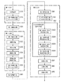
図1に示すように、ティシュペーパの製造装置は、三つのパートP1,P2,P3に大別される。
第一パートP1では、図2に示す抄紙機1によって、帯状の原紙W(抄造体,シート)が抄造(抄紙)される。
[1. Manufacturing equipment]
The configuration of the device for manufacturing the tissue paper is outlined.
As shown in FIG. 1, the tissue paper manufacturing apparatus is roughly divided into three parts P 1 , P 2 , and P 3 .
In the first part P 1, the paper machine 1 shown in FIG. 2, the strip of sheet W (papermaking product, sheet) is papermaking (paper).
第二パートP2では、図3に示す積層機3によって、第一パートP1で抄造された原紙Wどうしが重ね合わせられる。
なお、重ね合わせられた後の原紙Wについては、二層構造(いわゆる2プライ)であり、重ね合わせられる前の一層構造(いわゆる1プライ)の原紙Wとは構造が異なるものの、可読性に配慮して単に「原紙W」と称する。
In the second part P 2, the laminating
The base paper W after being overlapped has a two-layer structure (so-called 2-ply), and although the structure is different from that of the base paper W having a single-layer structure (so-called 1-ply) before being overlapped, consideration is given to readability. Is simply referred to as "base paper W".
第三パートP3では、図4に示す折畳機5によって、第二パートP2で重ね合わせられた原紙Wが折り畳まれる。
そして、所定の搬送方向寸法に原紙Wが分断される。このように分断されるまでの原紙Wは、張架された状態で搬送される。ここでいう「張架された状態」とは、搬送方向に沿う張力(テンション)が印加された状態かつロール間に架け渡された状態を意味する。原紙Wは、搬送時に印加された張力が保持された状態で保管もされる。これらより、抄造されてから分断されるまでの原紙Wは、張力が印加された状態が保持される。
In the third part P 3, by
Then, the base paper W is divided into predetermined transport direction dimensions. The base paper W until it is divided in this way is conveyed in a stretched state. The "tensioned state" as used herein means a state in which tension is applied along the transport direction and a state in which the rolls are stretched. The base paper W is also stored in a state where the tension applied during transportation is maintained. From these, the base paper W from the time of papermaking to the time of being divided is maintained in a state in which tension is applied.
第一パートP1において、抄造された原紙Wが巻き取られる。原紙Wは、第二パートP2に運搬される。そして、原紙Wが繰り出される。同様に、第二パートP2において、重ね合わせられた原紙Wが巻き取られる。原紙Wは、第三パートP3に運搬される。そして、原紙Wが繰り出される。 In the first part P 1, papermaking base paper W is wound. Paper W is conveyed to the second part P 2. Then, the base paper W is fed out. Similarly, in the second part P 2, the base paper W that has been superimposed is wound. Paper W is conveyed to the third part P 3. Then, the base paper W is fed out.
すなわち、第一パートP1の下流に第一巻取パート15(図2参照)が設けられ、第二パートP2の上流に第一繰出パート30(図3参照)が設けられる。また、第二パートP2の下流に第二巻取パート38(図3参照)が設けられ、第三パートP3の上流に第二繰出パート50(図4参照)が設けられる。さらに、第一パートP1と第二パートP2との間に第一運搬パートP12(第一運搬部)が設けられ、第二パートP2と第三パートP3との間に第二運搬パートP23(第二運搬部)が設けられる。 That is, the first take-up part 15 (see FIG. 2) is provided downstream of the first part P 1 , and the first feeding part 30 (see FIG. 3) is provided upstream of the second part P 2 . Further, a second winding part 38 (see FIG. 3) is provided downstream of the second part P 2, and a second feeding part 50 (see FIG. 4) is provided upstream of the third part P 3 . Further, a first transport part P 12 (first transport unit) is provided between the first part P 1 and the second part P 2, and a second transport part P 12 is provided between the second part P 2 and the third part P 3 . Transport part P 23 (second transport section) is provided.
搬送される原紙Wは、第一パートP1および第二パートP2で巻き取られることにより張力が印加される。平たく言えば、第一パートP1および第二パートP2の巻き取りによって、原紙Wが搬送方向に沿って引っ張られる。
以下、抄紙機1,積層機3および折畳機5の各構成を述べる。
Tension is applied to the base paper W to be conveyed by being wound up by the first part P 1 and the second part P 2 . To put it plainly, the winding of the first part P 1 and the second part P 2 pulls the base paper W along the transport direction.
Hereinafter, each configuration of the paper machine 1, the laminating
[1−1.抄紙機]
図2を参照して、抄紙機1の構成を詳述する。
抄紙機1は、原料から帯状の原紙Wを抄造するティシュマシンである。
抄紙機1には、原紙Wを抄造する抄紙パート10(抄造部)が設けられている。そのほか、抄紙パート10で抄造された原紙Wを巻き取る第一巻取パート15(第一巻取部)も設けられている。
[1-1. Paper machine]
The configuration of the paper machine 1 will be described in detail with reference to FIG.
The paper machine 1 is a tissue machine that makes a strip-shaped base paper W from a raw material.
The paper machine 1 is provided with a paper making part 10 (paper making section) for making a base paper W. In addition, a first winding part 15 (first winding section) for winding the base paper W made in the
抄紙パート10は、原料から湿った状態の原紙W(湿紙)を抄造するワイヤパート11,湿った状態の原紙Wから水分を圧搾するプレスパート12,水分が圧搾された原紙Wを乾燥させるドライヤパート13,乾燥した原紙Wの平滑度を高めるカレンダパート14に細別される。カレンダパート14によって平滑度の高められた原紙Wが第一巻取パート15で巻き取られる。
以下、抄紙機1の各パート11,12,13,14,15を製造工程順に説明する。
The
Hereinafter, each
〈ワイヤパート〉
ワイヤパート11には、原紙Wの原料であるスラリーを射出するヘッドボックスHが設けられている。スラリーには、パルプ繊維の懸濁した原料液が用いられる。
ワイヤパート11には、フォーミングロールRTの外周に一部が巻き掛けられた二種のワイヤベルトBT,BCが設けられている。
<Wire part>
The
The
ワイヤベルトBT,BCは、ベルト搬送ロールに巻き掛けられたメッシュ状の無端ベルトである。フォーミングワイヤベルトBTは、スラリーに対してフォーミングロールRT側とは反対側(外周側)に巻き掛けられ、搬送ワイヤベルトBCは、スラリーに対してフォーミングロールRT側(内周側)に巻き掛けられる。
フォーミングロールRTの外周においてワイヤベルトBT,BCどうしの間に射出されたスラリーが脱水されることにより、湿った状態の原紙Wが抄造される。
The wire belts B T and B C are mesh-shaped endless belts wound around a belt transport roll. The forming wire belt B T is wound around the slurry on the side opposite to the forming roll R T side (outer peripheral side), and the conveying wire belt B C is on the forming roll R T side (inner circumference side) with respect to the slurry. Wrapped around.
A wet base paper W is produced by dehydrating the slurry ejected between the wire belts B T and B C on the outer circumference of the forming roll R T.
図2に示すように、ヘッドボックスHには、フォーミングワイヤベルトBT側(外周側)に第一原料液を射出する第一射出口HE1と、搬送ワイヤベルトBC側(内周側)に第二原料液を射出する第二射出口HE2とが設けられている。第二原料液よりも第一原料液のほうが懸濁するパルプの繊維長が短く設定される。 As shown in FIG. 2, the head box H has a first injection port HE1 for injecting the first raw material liquid to the forming wire belt B T side (outer peripheral side) and a transport wire belt B C side (inner peripheral side). Is provided with a second injection port HE2 for injecting the second raw material liquid. The fiber length of the pulp suspended in the first raw material liquid is set shorter than that in the second raw material liquid.
原紙Wは、搬送されるワイヤベルトBT,BC上で搬送される際にスラリーから抄造されるため、パルプが搬送方向に沿う配向をなす。そのため、原紙Wは、幅方向に沿っては裂けにくく長手方向に沿っては裂けやすい引き裂き強度の指向性をもつ。
原紙Wは、搬送ワイヤベルトBCによって、次のプレスパート12へ搬送される。
Base paper W, the wire belt B T to be conveyed, since the papermaking from the slurry as it is carried on B C, forming an orientation in which the pulp is along the conveying direction. Therefore, the base paper W has a directivity of tear strength that is difficult to tear along the width direction and easy to tear along the longitudinal direction.
Base paper W is the delivery wire belt B C, is conveyed to the
〈プレスパート〉
プレスパート12には、ベルト搬送ロールに巻き掛けられた吸水性の搬送ベルトBAが設けられている。搬送ベルトBAには、吸水性をもつ材料(たとえばフェルト)の無端ベルトが用いられる。
搬送ベルトBAのうち上流側の部位は、上記した搬送ワイヤベルトBCで搬送される原紙Wに対して付勢された状態に設けられる。
<Press part>
The
The upstream portion of the transport belt B A is provided in a state of being urged with respect to the base paper W transported by the transport wire belt B C described above.
ベルト搬送ロールのうち、原紙Wに対して付勢する箇所の搬送ワイヤベルトBCが巻き掛けられるロールには、原紙Wを吸引するサクション機構MSの内蔵されたサクションロールRAが設けられている。サクションロールRAによって、原紙Wの搬送経路が搬送ワイヤベルトBC上から搬送ベルトBA上に切り替えられる。
原紙Wに対する搬送ワイヤベルトBCの付勢箇所において、原紙Wから水分が圧搾される。このようにして脱水された原紙Wは、搬送ベルトBAによって、次のドライヤパート13へ搬送される。
Of the belt transport rolls, the roll around which the transport wire belt B C is wound at the portion urging the base paper W is provided with a suction roll RA having a suction mechanism M S for sucking the base paper W. There is. The suction roll RA switches the transport path of the base paper W from the transport wire belt B C to the transport belt B A.
In urging portions of the conveyor wire belt B C against sheet W, water is squeezed from the sheet W. Such base paper W dewatered in the can by the conveyor belt B A, is conveyed to the
〈ドライヤパート〉
ドライヤパート13には、原紙Wを乾燥させる乾燥ロールRD(「ヤンキーロール」とも称される)が設けられている。
乾燥ロールRDには、搬送ベルトBAのうち下流側の部位が原紙Wを介して付勢されている。搬送ベルトBAで搬送された原紙Wは、回転する乾燥ロールRDの外周面上へ張り付くように移行する。乾燥ロールRDは、たとえば筒内に導入された蒸気によって筒面が加熱され、その筒面上の原紙Wを乾燥させる。
<Dryer part>
The
On the drying roll R D , a portion of the transport belt B A on the downstream side is urged via the base paper W. The base paper W transported by the transport belt B A shifts so as to stick to the outer peripheral surface of the rotating drying roll R D. In the drying roll RD , for example, the cylinder surface is heated by the steam introduced into the cylinder, and the base paper W on the cylinder surface is dried.
ドライヤパート13には、乾燥した原紙Wを乾燥ロールRDから剥離させるドクターブレードDDが設けられている。
ドクターブレードDDは、乾燥ロールRDの筒面に対して刃先が突き当てられた姿勢で配置される。ドクターブレードDDは、乾燥ロールRDから剥離する原紙Wにクレープ(縮緬状の皺)を付与する。原紙Wには、密に皺寄せられた箇所や疎に皺寄せられた箇所の混在したクレープが付与される。
The
The doctor blade D D is arranged in a posture in which the cutting edge is abutted against the tubular surface of the drying roll R D. The doctor blade D D imparts a crepe (crepe-like wrinkle) to the base paper W peeled from the drying roll R D. The base paper W is provided with a crepe in which densely wrinkled parts and sparsely wrinkled parts are mixed.
乾燥ロールRDに対するドクターブレードDDの突き当て角度や剥離された原紙Wの搬送速度に応じて、原紙Wに付与されるクレープの状態が変化する。逆に言えば、ドクターブレードDDの突き当て角度や乾燥ロールRDから剥離された原紙Wの搬送速度を制御することにより、原紙Wに付与されるクレープの状態を調節することが可能である。
このようにして乾燥ロールRDから剥離された原紙Wは、次のカレンダパート14へ搬送される。
Drying rolls R in accordance with the conveyance speed of the abutment angle or exfoliated sheet W of the doctor blade D D for D, crepe condition applied to the base paper W changes. Conversely, by controlling the conveying speed of the doctor blade D D abutment angle and drying roll R D fiberboard W peeled from, it is possible to adjust the state of crepe imparted to the base paper W ..
The base paper W peeled off from the drying roll RD in this way is conveyed to the
〈カレンダパート〉
カレンダパート14には、一対のカレンダロールRLが設けられている。カレンダロールRLは、原紙Wの搬送速度に応じた速度で回転し、搬送される原紙Wを挟み込んだ状態で互いに対向して配置される。カレンダロールRLどうしの間で原紙Wが厚み方向に圧縮される。
このようにしてカレンダ処理された原紙Wは、次の第一巻取パート15へ搬送される。
<Calendar part>
The
The base paper W calendered in this way is conveyed to the next first winding
〈第一巻取パート〉
第一巻取パート15には、原紙Wを巻き取る第一巻取ロールRW1が設けられている。第一巻取ロールRW1に帯状の原紙Wが巻き取られて第一原反ロールWR1が製造される。第一巻取パート15は、原紙Wが引っ張られて巻き取られることから、第一テンションパート(第一テンション部)や第一張力印加パート(第一張力印加部)とも言える。
以下の説明では、半製品(中間体)の第一原反ロールWR1について、装置構造をなすロールとの混同を防ぐため、「第一原反ロールWR1」を「第一原反WR1」と略称する。
<First winding part>
The first
In the following description, for the Ichihara roll W R1 of the semi-finished product (intermediate), in order to prevent confusion with the roll forming apparatus structure, "the Ichihara roll W R1" and "first raw W R1 Is abbreviated.
[1−2.積層機]
図3を参照して、積層機3の構成を詳述する。
積層機3は、原紙Wどうしを重ね合わせるプライマシンである。積層機3では、二つの第一原反WR1,WR1が設置され、第一原反WR1,WR1から繰り出された原紙Wどうしが積層される。すなわち、原紙Wが二層構造となる。
[1-2. Laminating machine]
The configuration of the
The laminating
積層機3には、各第一原反WR1から原紙Wを繰り出す第一繰出パート30(第一繰出部)や原紙Wを巻き取る第二巻取パート38(第二巻取部)に加えて、第一繰出パート30で繰り出された原紙Wどうしを重ね合わせる積層パート32(積層部)が設けられている。積層機3には、積層パート32で重ね合わせられた二層の原紙Wどうしを係合させる係合パート35(係合部)が設けられ、係合された原紙Wを裁断する裁断パート36(裁断部)も設けられている。積層機3には、二層どうしが係合された原紙Wを湿潤させる湿潤パート37(湿潤部)も設けられている。積層パート32と係合パート35との間には、カレンダパート33が設けられている。
以下、積層機3の各パート30,32,33,35,36,37,38を製造工程順に説明する。
The
Hereinafter, each
〈第一繰出パート〉
第一繰出パート30では、それぞれに第一原反WR1の設置された二つの第一繰出ロールRU1,RU1が設けられ、第一繰出ロールRU1の第一原反WR1から各原紙Wが繰り出される。
このように繰り出された原紙Wは、次の積層パート32へ搬送される。
<First delivery part>
In the
The base paper W unwound in this way is conveyed to the next
〈積層パート〉
積層パート32には、外周の一部に二つの原紙Wが重畳して巻き回される積層ロールRPが設けられている。積層ロールRPで二つの原紙Wが重ね合わせられる。
このように重ね合わせられた原紙Wについては、外側を向く二面のうち一方を第一面F1(一方の原紙Wの表面FF)とし、他方を第二面F2(他方の原紙Wの表面FF)とする。
上記のように積層された原紙Wは、次のカレンダパート33へ搬送される。
<Laminated part>
The
Regarding the base paper W stacked in this way, one of the two outward facing sides is designated as the first side F 1 (the surface F F of one base paper W), and the other side is the second side F 2 (the other base paper W). surface F F) to be of.
The base paper W laminated as described above is conveyed to the
〈カレンダパート〉
カレンダパート33には、カレンダパート14と同様のカレンダロールRL1,RL2が二組設けられ、原紙Wに対して二段階にカレンダ処理を施す。
このようにカレンダ処理された原紙Wは、次の係合パート36へ搬送される。
<Calendar part>
The
The base paper W calendered in this way is conveyed to the next engaging
〈係合パート〉
係合パート35には、原紙Wの一部を厚み方向に係合させる係合ロールRCが設けられている。係合ロールRCには、凸ロールRC1および受ロールRC2が設けられている。凸ロールRC1および受ロールRC2は、原紙Wの搬送速度に応じた速度で回転し、原紙Wを挟んで互いに対向して配置される。凸ロールRC1には、原紙Wのうち端縁に沿う箇所に対応して外周に凸部が設けられている。この凸部は、受ロールRC2の外周に突き当てられ、受け止められる。
<Engagement part>
The engaging
凸ロールRC1の凸部が原紙Wを介して受ロールRC2の外周に突き当てられることにより、原紙Wが厚み方向に交絡した状態となる。言い換えれば、原紙Wの二層が互いに噛み込んだ状態となり、二層構造の層どうしが一体的に係合する。
受ロールRC2の外周が金属製であり、凸ロールRC1の凸部が原紙Wに対して受ロールRC2側に突出しにくい構造が採用されている。そのため、係合パート35で係合処理された原紙Wは、凸ロールRC1側の一部(たとえば搬送方向に沿う線状の部位)が凹設され、受ロールRC2側はほぼ平坦状をなす。このような係合構造は、「クリンパ」や「コンタクタエンボス」とも称され、両面に凹凸をもつエンボスとは構造的に相異する。
上記のように係合処理された原紙Wは、次の裁断パート36へ搬送される。
When the convex portion of the convex roll R C1 is abutted against the outer periphery of the receiving roll R C2 via the base paper W, the base paper W is in a state of being entangled in the thickness direction. In other words, the two layers of the base paper W are in a state of being bitten into each other, and the layers of the two-layer structure are integrally engaged with each other.
The outer circumference of the receiving roll R C2 is made of metal, and a structure is adopted in which the convex portion of the convex roll R C1 does not easily protrude toward the receiving roll R C2 with respect to the base paper W. Therefore, in the base paper W engaged in the engaging
The base paper W engaged as described above is conveyed to the next cutting
〈裁断パート〉
裁断パート36には、長手方向に沿って原紙Wを裁断するスリッタSが設けられている。スリッタSは、裁断箇所の幅方向位置に応じたさまざまな幅方向寸法に原紙Wを断裁することができる。たとえば、原紙Wに対して幅方向位置が調節可能に設けられた刃(カッタ)および刃受けロールがスリッタSに設けられる。
<Cut part>
The cutting
裁断パート36では、原紙Wの裁断寸法が所定の幅方向寸法に設定されている。
「所定の幅方向寸法」とは、折畳機5(図4参照)に設置される原紙Wの幅方向寸法を意味する。この幅方向寸法としては、完成したティシュペーパのうち端辺(長辺または短辺)の寸法(すなわち製品幅)やこの整数倍の寸法などが挙げられる。
このような幅方向寸法に裁断された各原紙Wは、次の湿潤パート37へ搬送される。
In the cutting
The "predetermined width direction dimension" means the width direction dimension of the base paper W installed in the folding machine 5 (see FIG. 4). Examples of the width direction dimension include the dimension of the end side (long side or short side) of the completed tissue paper (that is, the product width) and the dimension obtained by an integral multiple of this.
Each base paper W cut to such a width direction dimension is conveyed to the next
〈湿潤パート〉
湿潤パート37には、原紙Wを湿潤させる装置が設けられている。この湿潤装置として、ここでは(図3には)原紙Wの両面F1,F2に水を吹き付ける噴霧器A1,A2(マルチ湿潤部)を例示する。詳細には、原紙Wの第一面F1に水分を含有させる第一噴霧器A1と、原紙Wの第二面F2に水分を含有させる第二噴霧器A2とが設けられている。
湿潤パート37は、上記したように水を原紙Wに含有させて湿潤度合いを増加させることから、加湿パート(加湿部)とも言える。
このようにして含水した原紙Wは、次の第二巻取パート38へ搬送される。
<Wet part>
The wetting
The
The base paper W moistened in this way is conveyed to the next second winding
〈第二巻取パート〉
第二巻取パート38には、第一巻取パート15と同様に、原紙Wを巻き取る第二巻取ロールRW2が設けられている。第二巻取ロールRW2に帯状の原紙Wが巻き取られて第二原反ロールWR2が製造される。第二巻取パート38では、第一巻取パート15と同様に、原紙Wが引っ張られつつ巻き取られることから、第二テンションパート(第二テンション部)や第二張力印加パート(第二張力印加部)とも言える。なお、第二原反ロールWR2についても、装置構造をなすロールとの混同を防ぐため、「第二原反WR2」と略称する。
<Second winding part>
The second volume collected by
[1−3.折畳機]
図4を参照して、折畳機5の構成を詳述する。
折畳機5は、原紙Wを折り畳むインターフォルダである。折畳機5には、いわゆるマルチスタンド方式のインターフォルダ(「多連機」とも称される)が採用されており、製品状態で包装される枚数(ティシュ箱に収容される枚数)に応じた多数の第二原反WR2が設置される。
[1-3. Folding machine]
The configuration of the
The
折畳機5には、各第二原反WR2から原紙Wを繰り出す第二繰出パート50(第二繰出部)や原紙Wを折り畳む折畳パート54(折畳部)に加えて、第二繰出パート50で繰り出された後であって折畳パート54で折り畳まれる前の原紙Wに薬剤を塗布する塗布パート52(塗布部)が設けられている。折畳機5には、薬剤の塗布される前の原紙Wに凹凸(エンボス)を形成(付与)するエンボス形成パート51(エンボス形成部)が設けられている。折畳機5には、折畳パート54で折り畳まれた原紙Wを分断する分断パート56(分断部)および分断パート56で分断された原紙Wの包装パート58(包装部)も設けられている。
The
一台の第二繰出パート50には、二つの第二原反WR2が設置(たとえば並設)される。製品状態で包装される二枚で一組のティシュを製造する場合には、第二繰出パート50に設置される二つの第二原反WR2はそれぞれ二層構造であることから、一つの第二原反WR2からは一組(二枚の原紙Wが重なっている状態)のティシュが製造される。つまり、一台の第二繰出パート50から二組のティシュが製造される。すなわち、製品状態で包装されるティシュ(一箱のティシュ)における総組数の半数と同台数の第二繰出パート50が設置される。
エンボス形成パート51,塗布パート52および折畳パート54は、第二繰出パート50と同様に、多数の箇所に設けられる。一方、分断パート56および包装パート58は、折畳機5の下流において一箇所に設けられる。
On a single
The embossing
以下、折畳機5の各パート50,51,52,54,56,58を製造工程順に説明する。
上流側のパート50,51,52,54については図4(A)を参照し、下流側のパート56,58については図4(B)を参照して詳述する。
Hereinafter, each
The
〈第二繰出パート〉
第二繰出パート50では、第二原反WR2が設置された第二繰出ロールRU2が設けられ、第二繰出ロールRU2の第二原反WR2から原紙Wが繰り出される。
このように繰り出された原紙Wは、次のエンボス形成パート51へ搬送(導出)される。
<Second delivery part>
In the
The base paper W unwound in this way is conveyed (delivered) to the next
〈エンボス形成パート〉
エンボス形成パート51は、所定の幅方向寸法に裁断された原紙Wに凹凸を形成する(このことからエンボス形成パート51は「裁断後エンボス形成部」とも言える)。
エンボス形成パート51には、原紙Wに凹凸を形成する一対のエンボスロールREが原紙Wを挟んで互いに対向して配置されている。エンボスロールREの周面には、原紙Wに形成される凹凸に対応する凸凹が刻設されている。
エンボス形成パート51では、エンボスロールREの凸凹が原紙Wに押し付けられて、原紙Wに凹凸が形成される。
<Embossing part>
The
In the
In the
エンボス形成パート51では、両面エンボス方式が採用され、第一面F1に凹凸を形成する第一エンボスロールRE1と、第二面F2に凹凸を形成する第二エンボスロールRE2とが設けられる。図4(A)に例示するように、原紙Wに凹凸が形成される箇所(エンボスロールRE1,RE2のニップ箇所)において、第一エンボスロールRE1の凸凹と第二エンボスロールRE2の凸凹とが互い違いに原紙Wを押し付ける両面エンボス方式が用いられている。
In the
ただし、エンボスロールの凸凹のうち凸部どうしが突き合せられる両面エンボス方式を用いてもよく、一方のエンボスロールのみが凸凹をもつ片面エンボス方式を用いてもよい。片面エンボス方式では、他方のエンボスロールにゴムロールが用いられ、原紙の凹凸形成面とは反対の面にも凹凸が形成される。
エンボス形成パート51は、原紙Wに凹凸を形成してエンボスを付与することから、エンボス付与パート(エンボス付与部)とも言える。
上記したように凹凸が形成された原紙Wは、次の塗布パート52へ搬送される。
However, a double-sided embossing method in which the convex portions of the embossing rolls are butted against each other may be used, or a single-sided embossing method in which only one embossing roll has unevenness may be used. In the one-sided embossing method, a rubber roll is used for the other embossing roll, and unevenness is formed on the surface opposite to the uneven forming surface of the base paper.
Since the
The base paper W on which the unevenness is formed as described above is conveyed to the
〈塗布パート〉
塗布パート52では、原紙Wに薬剤が塗布される。
この薬剤としては、保湿剤や芳香剤をはじめ、医療成分,清涼剤,顔料といったさまざまな液剤が挙げられる。たとえば、原紙Wの保湿機能を高める機能性の薬剤として、グリセリンやソルビトールが水溶した保湿液(薬液)が用いられる。
<Applying part>
In the
Examples of this drug include various liquid agents such as moisturizers and air fresheners, medical ingredients, refreshing agents, and pigments. For example, a moisturizer (chemical solution) in which glycerin or sorbitol is dissolved is used as a functional agent for enhancing the moisturizing function of the base paper W.
塗布パート52には、原紙Wの両面F1,F2をそれぞれ塗工する二つの塗布パート52A,52B(マルチ塗布部)が設けられている。原紙Wの第一面F1は、第一塗布パート52A(第一塗布部)によって塗工される。原紙Wの第二面F2は、第二塗布パート52B(第二塗布部)によって塗工される。
塗布パート52A,52Bでは、原紙Wに対する薬剤の塗布方向が同方向に設定される。言い換えれば、塗布パート52A,52Bは、所定方向から薬剤を原紙Wに塗布する。ここでは、薬剤塗布に関する所定方向として鉛直方向上側からとしたもの(すなわち上方からの薬剤の塗工)を例示する。
The
In the
塗布パート52には原紙Wの向きを反転させる反転ローラRR1,RR2(面返し部)が設けられ、塗布パート52A,52Bのそれぞれで両面F1,F2が上方(一方向)を向き、上記した塗布を可能としている。
表裏反転ローラRR1は第二繰出パート50と第一塗布パート52Aとの間に配置され、裏表反転ローラRR2は第一塗布パート52Aと第二塗布パート52Bとの間に配置される。
図4(A)には、二つの表裏反転ローラRR1および二つの裏表反転ローラRR2を例示する。ただし、反転ローラRR1,RR2の設置数は、原紙Wの搬送経路や周囲の構成,要求仕様などに応じて設定すればよく、単数であっても三つ以上の複数であってもよい。
The
The reversing roller R R1 disposed between the
FIG. 4A illustrates two front-back reversing rollers R R1 and two front-rear reversing rollers R R2 . However, the number of reversing rollers R R1 and R R2 installed may be set according to the transport path of the base paper W, the surrounding configuration, the required specifications, etc., and may be a single number or a plurality of three or more. ..
反転ローラRR1,RR2は、下記のように原紙Wの向きを反転させる。
表裏反転ローラRR1に進入する直前の原紙Wは、第一面F1が上方を向き、第二面F2が下方を向いている。つづいて、表裏反転ローラRR1によって両面F1,F2の向きが反転し、第一面F1が下方を向くとともに第二面F2が上方を向き、第一塗布パート52Aで下方から第一面F1に薬剤が塗布される。その後、裏表反転ローラRR2によって再び両面F1,F2の向きが反転し、第一面F1が上方を向くとともに第二面F2が下方を向き、第二塗布パート52Bで下方から第二面F2に薬剤が塗布される。
The reversing rollers R R1 and R R2 reverse the orientation of the base paper W as shown below.
In the base paper W immediately before entering the front-back reversing roller R R1 , the first surface F 1 faces upward and the second surface F 2 faces downward. Next, the directions of both sides F 1 and F 2 are reversed by the front and back reversing rollers R R1 , the first surface F 1 faces downward and the second surface F 2 faces upward, and the
塗布パート52A,52Bには、親液性をもつ布状の塗布部材6と、塗布部材6に薬剤を供給する供給装置7とを備えた塗工装置20が用いられている。塗工装置20は、供給装置7から供給される薬剤を、塗布部材6を介して、被塗布物としての原紙Wに塗るものである。
ここでいう「親液性」とは、薬剤が浸透可能な性質を意味する。つまり、塗布部材6は、薬剤が染み込むことと、染み出ることとの双方が可能な性質をもつ。また、ここでいう「布状」とは、可撓性をもつ(柔軟である)ことを意味する。
For the
The term "parental fluid" as used herein means a property through which a drug can penetrate. That is, the
図5に示すように、本実施形態の塗工装置20は、搬送されている原紙Wの上方から塗布部材6を垂れ下げる支持部材8を更に備えている。支持部材8は、塗布部材6の上端部を支持する竿のようなものであり、原紙Wの搬送経路に対して、その位置が固定されている。ここでは、支持部材8が原紙Wの幅方向の両側に跨るゲート状に設けられている場合を例示する。
As shown in FIG. 5, the
塗布部材6は、多孔質体で形成される。塗布部材6としては、たとえば、ろ紙や布やフェルトなどが適用されうる。本実施形態の塗布部材6はほぼ矩形状である。
以下、塗布部材6について、原紙Wの幅方向と同じ方向を幅方向とする。また、塗布部材6の延在面において幅方向と直交する方向を長手方向とする。本実施形態の塗布部材6は、原紙Wの両面F1,F2のほぼ全域に薬剤を塗布しうるように、幅方向寸法が原紙Wの幅方向寸法とほぼ同一に設定されている。
The
Hereinafter, the width direction of the
塗布部材6は、搬送されている原紙Wから離隔した位置において支持部材8により支持された支持部6c(第一支持部)を有する。本実施形態では、支持部6cが塗布部材6の上端部(長手方向の一端部)である場合を例示する。以下、支持部6cを「上端部6c」ともいう。
塗布部材6は、上端部6cが支持されることにより、原紙Wの上方で暖簾のように垂れ下がっている。塗布部材6は、上端部6cから垂れ下がった部分の下端部(長手方向の他端部)に、原紙Wに接するように設けられた塗工部6aを有する。
The
The
塗工部6aは、搬送される原紙Wに対して直接的に接するのではなく、薬剤を介して間接的に接するように設けられている。本実施形態の塗工部6aは面状である。つまり、塗工部6aは、薬剤を介して原紙Wに面接触するように、塗布部材6の幅方向だけでなく長手方向にも広がって設けられている。
塗布部材6は、供給装置7から供給された薬剤を、塗工部6aから染み出させて原紙Wに塗布する。
The
The
図6に示すように、塗布部材6は、薬剤の塗布時に側面視で(幅方向の外側から視て)鈍角のL字型をなす。以下、塗布部材6の上端部6cから塗工部6aにかけて下降傾斜する部分を斜面部6bという。斜面部6bは、薬剤の塗布時に塗工部6aによって下流側に引っ張られることで、鉛直方向(重力が作用する方向)に対して傾斜する面状の部位である。
斜面部6bの下端部は、緩やかに湾曲して塗工部6aに接続する。言い換えると、塗布部材6のうち、塗工部6aから上流側に延びる部分には角が形成されないようになっている。
As shown in FIG. 6, the
The lower end of the
塗布部材6の形状および寸法は、上述したものに限られず、薬剤を塗布する面積や塗布量などに応じて適宜設定される。たとえば、薬剤を塗布する幅方向領域を縮小する場合には、塗工部6aの幅方向寸法を小さくすればよい。また、薬剤の塗布量(原紙Wに形成される塗布膜の厚み)を抑える場合には、塗工部6aの長手方向寸法を小さくする、あるいは斜面部6bの長手方向寸法を大きくすればよい。
The shape and dimensions of the
図5および図6に示すように、供給装置7は、塗布部材6に向けて薬剤を送る送給部71と、送給部71に薬剤を供給する供給部72とを有する。ここでは、供給部72が、薬剤を貯留するタンク72Aと、タンク72Aから塗布部材6の上方まで延設された供給管72Bと、供給管72Bに介装されたポンプ72Cとで構成され、送給部71が供給管72Bに形成された複数の孔部である場合を例示する。
As shown in FIGS. 5 and 6, the supply device 7 has a
供給部72は、ポンプ72Cを駆動することで、タンク72A内の薬剤を供給管72Bに流通させる。送給部71は、下方に向かって開口した孔部であって、塗布部材6の斜面部6bの鉛直上方に位置するように設けられ、供給管72Bを流れる薬剤を斜面部6bに向けて滴下させる。送給部71から塗布部材6に供給される薬剤の量(単位時間当りの滴下量)は、ポンプ72Cの駆動状態を制御することにより調整可能である。
By driving the pump 72C, the supply unit 72 distributes the medicine in the
塗布量は、上述した塗工部6aや斜面部6bの寸法を変更することのほか、たとえば、ポンプ72Cの駆動状態や、塗布部材6の材質(薬剤の浸透率)を変更することによっても変更可能である。
上記したように薬剤が塗布された原紙Wは、次の折畳パート54へ搬送される。
The coating amount can be changed not only by changing the dimensions of the
The base paper W coated with the chemical as described above is conveyed to the
〈折畳パート〉
折畳パート54には、折畳機構として折板Pを用いて原紙Wを折り畳む機構(折板式,原紙Wの折畳形態はポップアップ方式)が採用されている。
折畳パート54には、原紙Wを折り畳む折板Pのほか、原紙Wの幅方向に交差して配置された傾斜ロールCRI1,CRI2や一組の原紙W,Wどうしを離間させる離間ロールCRS1,CRS2といった種々の搬送ロールが設けられている。
<Folding part>
In the
In the
折畳パート54は、第一面F1が外側の状態であって第二面F2が内側の状態で原紙Wを折り畳み、折板Pによる折り目を原紙Wの搬送方向に沿って形成する。
上記したように折り畳まれた原紙Wは、並設された他の第二繰出パート50,エンボス形成パート51,塗布パート52,エンボス形成パート53および折畳パート54を経て折り畳まれた原紙Wと積み重ねられ、搬送ベルトBIによって、次の分断パート56へ搬送される。
In the
The base paper W folded as described above is stacked with the base paper W folded through the other
〈分断パート〉
分断パート56には、幅方向に沿って原紙Wを裁断するカッタCが設けられている。このように裁断された原紙Wは、長手方向に亘る連続が分断される。このように分断されることで、原紙Wに対して印加されていた搬送方向に沿う張力が解除される。このことから、薬剤が塗布された原紙Wは、巻き取られずに、積層され、折り畳まれるものと言える。第一パートP1の第一巻取パート15,第二パートP2(パート30,32,33,35,36,38)第二運搬パートP23,第三パートP3の第二繰出パート50などの分断パート56よりも上流側は、原紙Wに印加された張力が保持されることから、張力保持パート(張力保持部)とも言える。
<Division part>
The dividing
カッタCは、裁断タイミング(ここでは上下動の制御間隔)に応じてさまざまな搬送方向寸法に原紙Wを断裁することができる。たとえば、カッタCの裁断間隔が長いほど、裁断後に原紙Wが搬送される距離が延びることから、搬送方向寸法の長い原紙Wが切り分けられる。
分断パート56は、上述した裁断パート36の下流で原紙Wを裁断することから、第二裁断パートとも言える。逆に、裁断パート36は、第一裁断パートとも言える。
The cutter C can cut the base paper W into various transport direction dimensions according to the cutting timing (here, the vertical movement control interval). For example, the longer the cutting interval of the cutter C, the longer the distance that the base paper W is conveyed after cutting, so that the base paper W having a long transport direction dimension is cut.
Since the dividing
原紙Wの裁断寸法は、所定の搬送方向寸法に設定されている。
「所定の搬送方向寸法」とは、完成したティシュペーパのうち、上述した所定の幅方向寸法に裁断された端辺に対して直交する端辺の寸法を意味する。具体的に言えば、ティシュペーパのうち、ティシュ箱の長手方向に沿う端辺の長さとして設定された寸法が、所定の搬送方向寸法に設定される。
The cutting dimension of the base paper W is set to a predetermined transport direction dimension.
The "predetermined transport direction dimension" means the dimension of the end side of the completed tissue paper that is orthogonal to the end edge cut to the above-mentioned predetermined width direction dimension. Specifically, the dimension set as the length of the end side of the tissue paper along the longitudinal direction of the tissue box is set to a predetermined transport direction dimension.
このように分断パート56で分断された原紙W(枚葉状の衛生用品)は、包装前のティシュペーパであり、次の包装パート58へ搬送される。
〈包装パート〉
包装パート58では、分断パート56で分断された原紙Wを包装用のカートン59(ティシュ箱)に収容する。
このように包装が完了すると、箱入りのティシュペーパが完成する。
The base paper W (sheet-leaf hygiene product) divided by the dividing
<Packaging part>
In the
When the packaging is completed in this way, the boxed tissue paper is completed.
[2.製造方法]
上述した製造装置を用いてティシュペーパを製造する方法を述べる。
本製造方法では、図7に示すように、はじめに、抄紙機1の製法に対応する第一工程(ステップS10およびS15)が実施される。それから、抄紙機1で巻き取られた第一原反WR1を積層機3へ運搬する第一運搬工程(ステップS20)が実施される。
その後、積層機3の製法に対応する第二工程(ステップS30〜S38)が実施される。それから、積層機3で巻き取られた第二原反WR2を折畳機5へ運搬する第二運搬工程(ステップS40)が実施される。
このように、第一工程,第二工程および第三工程の工程間には、原反WR1,WR2を移動させる運搬工程が実施される。
そして、折畳機5の製法に対応する第三工程(ステップS50〜S58)が実施される。
[2. Production method]
A method for manufacturing tissue paper using the above-mentioned manufacturing apparatus will be described.
In this manufacturing method, as shown in FIG. 7, first, the first steps (steps S10 and S15) corresponding to the manufacturing method of the paper machine 1 are carried out. Then, the first transportation step for transporting the first raw W R1 taken up by the paper machine 1 to laminator 3 (step S20) is performed.
After that, the second step (steps S30 to S38) corresponding to the manufacturing method of the
In this way, a transportation step of moving the raw fabrics WR1 and WR2 is carried out between the first step, the second step and the third step.
Then, the third step (steps S50 to S58) corresponding to the manufacturing method of the
第一工程では、抄紙パート10の製法に対応する抄造工程(ステップS10)が実施される。この抄造工程では、原料のスラリーから湿った状態の原紙Wを乾燥させ、原紙Wにクレープが付与される。
そして、第一巻取パート15で原紙Wを巻き取る第一巻取工程(ステップS15)が実施される。この第一巻取工程は、第一巻取パート15の別称に倣って、第一テンション工程や第一張力印加工程とも言える。
In the first step, a papermaking step (step S10) corresponding to the manufacturing method of the
Then, the first winding step (step S15) of winding the base paper W in the first winding
第二工程では、第一繰出パート30で原紙Wを繰り出す第一繰出工程(ステップS30)が実施される。つづいて、積層パート32で原紙Wを重ね合わせる積層工程(ステップS32)が実施される。
それから、カレンダパート33で原紙Wをカレンダ処理した後に、係合パート35で原紙Wどうしを係合する係合工程(ステップS35)が実施される。その後、裁断パート36で原紙Wを所定の幅方向寸法に裁断する裁断工程(ステップS36)が実施される。
In the second step, the first feeding step (step S30) of feeding the base paper W in the
Then, after the base paper W is calendered in the
それから、裁断された原紙Wを湿潤させる湿潤工程(ステップS37)が実施される。この湿潤工程は、原紙Wの両面F1,F2に水分を含有させる。また、湿潤パート37の別称に倣って、湿潤工程を加湿工程とも言える。
そして、第二巻取パート38で二層構造の原紙Wを巻き取る第二巻取工程(ステップS38)が実施される。この第二巻取工程は、第二巻取パート38の別称に倣って、「第二テンション工程」や「第二張力印加工程」とも言える。
Then, a wetting step (step S37) of wetting the cut base paper W is carried out. In this wetting step, water is contained in both sides F 1 and F 2 of the base paper W. Further, following the alias of the wetting
Then, the second winding step (step S38) of winding the base paper W having a two-layer structure is carried out in the second winding
第三工程では、第二繰出パート50で原紙Wを繰り出す第二繰出工程(ステップS50)が実施される。その後、エンボスロールREで原紙Wに凹凸を形成するエンボス形成工程(ステップS51)が実施される。このエンボス形成工程は、所定の幅方向寸法に裁断された原紙Wに凹凸を形成することから、裁断後エンボス形成工程とも言える。また、エンボス形成工程は、原紙Wに凹凸を形成してエンボスを付与することから、エンボス付与工程とも言える。
In the third step, the second feeding step (step S50) of feeding the base paper W in the
それから、塗布パート52で原紙Wに薬剤を塗布する塗布工程(ステップS52)が実施される。詳細には、原紙Wの両面F1,F2に薬剤を塗布するマルチ塗布工程(ステップS52)が実施される。
このマルチ塗布工程では、まず、表裏反転ローラRR1で原紙Wの向き反転させる第一面返し工程(ステップS522)が実施される。それから、第一塗布パート52Aで原紙Wの第一面F1に薬剤を塗布する第一塗布工程(ステップS524)が実施される。
Then, in the
In this multi-coating step, first, a first-side turning step (step S522) in which the orientation of the base paper W is reversed by the front-back reversing roller R R1 is carried out. Then, in the
その後、裏表反転ローラRR2で原紙Wの向きを再び反転させる第二面返し工程(ステップS526)が実施される。そして、第二塗布パート52Bで原紙Wの第二面F2に薬剤を塗布する第二塗布工程(ステップS528)が実施される。
本実施形態の塗工方法は、第一塗布工程および第二塗布工程のそれぞれにおいて採用されている。第一塗布工程および第二塗布工程では、図8に示す各処理(ステップS1〜S3)が実施される。まず、薬剤が浸透可能な塗布部材6に薬剤を供給する供給工程(ステップS1)が実施される。それから、薬剤を塗布部材6に浸透させる浸透工程(ステップS2)が実施される。そして、薬剤を塗布部材6の塗工部6aから染み出させて原紙Wに塗る塗工工程(ステップS3)が実施される。
なお、第一面返し工程および第二面返し工程は、薬剤を塗布する面を変更することから、面変更工程とも言える。
After that, a second flipping step (step S526) is carried out in which the orientation of the base paper W is reversed again by the front and back reversing rollers R R2 . Then, in the
The coating method of the present embodiment is adopted in each of the first coating step and the second coating step. In the first coating step and the second coating step, each process (steps S1 to S3) shown in FIG. 8 is carried out. First, a supply step (step S1) of supplying the drug to the
In addition, since the first surface turning step and the second surface turning step change the surface to which the chemical is applied, it can be said to be a surface changing step.
つづいて、折畳パート54で原紙Wを折り畳む折畳工程(ステップS54)が実施される。
その後、分断パート56で折り畳まれた原紙Wを所定の搬送方向寸法に分断する分断工程(ステップS56)が実施される。
このようにして、薬剤が塗布された原紙Wを巻き取ることなく、原紙Wの折り畳みや積層を実施する。
Subsequently, a folding step (step S54) of folding the base paper W in the
After that, a dividing step (step S56) of dividing the base paper W folded in the dividing
In this way, the base paper W is folded and laminated without winding up the base paper W coated with the chemicals.
そして、原紙W(ティシュペーパ)をカートン59に包装する。
このような手順でティシュペーパが製造される。
Then, the base paper W (tish paper) is wrapped in the
The tissue paper is manufactured by such a procedure.
[3.作用および効果]
[3−1.塗工装置および塗工方法]
本実施形態で開示する塗工装置20および塗工方法は、上述のように構成されるため、以下のような作用および効果を得ることができる。
以下、主に塗工装置20に関する作用および効果を述べる。
[3. Action and effect]
[3-1. Coating equipment and coating method]
Since the
Hereinafter, the action and effect of the
(1)供給装置7から塗布部材6に供給された薬剤は、塗布部材6に浸透して塗工部6aから染み出る。これにより、原紙Wに薬剤が塗布される。
このように、塗工装置20によれば、薬剤が浸透可能な塗布部材6を介して原紙Wに薬剤を塗布するため、たとえば供給装置7から塗布部材6に供給する薬剤の量を調整することにより、原紙Wに対する薬剤の塗布量を変更することができる。したがって、グラビア方式を用いる場合と比べて、塗布量の調整を容易にすることができる。
(1) The chemicals supplied from the supply device 7 to the
As described above, according to the
グラビア方式の塗工では、塗布量を増やす場合にグラビアロールの回転速度を上げる必要があり、グラビアロールの回転速度を抑えるにはグラビアロールの大径化(回転速度に対する周速度の増加)が必要となる。塗工装置20によれば、これらの必要がないため、塗布量を安定化させることができるとともに、装置の大型化を回避することができる。
In the gravure method coating, it is necessary to increase the rotation speed of the gravure roll when increasing the coating amount, and it is necessary to increase the diameter of the gravure roll (increase the peripheral speed with respect to the rotation speed) in order to suppress the rotation speed of the gravure roll. It becomes. According to the
また、グラビア方式では、グラビアロールとバックアップロールとで原紙Wを挟みながら塗工するため、原紙Wの両側にロールを配置する必要があり、装置が大型化しやすい。これに対し、塗工装置20によれば、これらのロールが不要であるため、原紙Wの片面側に装置の全体を収めることができる。したがって、省スペース化を実現することができる。
塗工装置20によれば、グラビアロールを用いないため、原紙Wに版目を付けることがなく、原紙Wの品質向上に寄与することができる。
Further, in the gravure method, since the base paper W is sandwiched between the gravure roll and the backup roll for coating, it is necessary to arrange the rolls on both sides of the base paper W, and the apparatus tends to be large. On the other hand, according to the
According to the
塗布部材6が布状であるため、薬剤を介して原紙Wに柔らかく接することができる。つまり、塗布部材6は、塗工部6aが薬剤を介して原紙Wに接した場合に自ら曲がるため、原紙Wに大きな押圧力をかけずに済む。これにより、塗工時に原紙Wにかかる負荷が緩和されることから、原紙Wに傷や破れが生じることを抑えられる。よって、原紙Wの品質向上に寄与することができる。
塗布部材6が布状であるため、たとえばブロック状である場合と比べて、薬剤の浸透速度を高くすることができる。これにより、供給装置7から塗布部材6への薬剤の供給量を変更した場合に、塗工部6aから染み出る薬剤の量がより速やかに変化することから、塗布量の変更に係る応答性を向上させることができる。
塗布部材6の塗工部6aが薬剤を介して原紙Wに接するように設けられているため、塗工部6aと原紙Wとの間に生じる摩擦力を低減することができる。この点からも、原紙Wの品質低下を抑制することができる。
Since the
Since the
Since the
(2)塗布部材6の塗工部6aが面状であるため、塗工部が点状または線状である場合と比べて、より確実に薬剤を原紙Wに塗布することができる。これにより、塗り残しの発生や濃淡差の発生を抑制することができる。また、塗工部6aから原紙Wにかかる荷重が分散されるため、原紙Wを傷つけにくくすることができる。
塗工部6aの大きさを変更し、薬剤を介して塗工部6aと原紙Wとが接触する面積を変化させれば、塗布量を変更することができる。
(2) Since the
The coating amount can be changed by changing the size of the
(3)塗布部材6が、上端部6cから垂れ下がった部分の下端部に塗工部6aを有するため、塗布部材6に浸透した薬剤が重力により塗工部6aに流れやすくなり、塗工部6aから薬剤を染み出しやすくすることができる。よって、より確実に薬剤を原紙Wに塗布することができる。
(3) Since the
(4)供給装置7が、供給部72から送給部71に供給した薬剤を送給部71から塗布部材6に向けて送るため、たとえば、供給部72から送給部71に供給する薬剤の量を調整することで、送給部71から塗布部材6に供給される薬剤の量を変更することができる。したがって、グラビア方式を用いる場合と比べて、塗布量の調整を容易にすることができる。
送給部71が塗布部材6に向けて薬剤を送るため、たとえば供給ロールからグラビアロールへとロール間で薬剤を受け渡す場合と比べて、薬剤をより確実に受け渡すことができる。これにより、塗布量の微調整を可能にすることができる。
(4) Since the supply device 7 sends the drug supplied from the supply unit 72 to the
Since the
(5)供給装置7が薬剤を滴下することにより塗布部材6に薬剤を供給するため、たとえば上述した供給管72Bに孔部を形成するだけで済み、薬剤を塗布部材6に向けて噴射する場合と比べて、装置構成を簡素化することができる。
塗布部材6のうち、鉛直方向に対して傾斜した斜面部6bに向けて薬剤を滴下させることにより、滴下した薬剤を塗布部材6に当てやすくすることができる。
(5) Since the supply device 7 supplies the drug to the
By dropping the drug toward the
塗布部材6では、斜面部6bの下端部が緩やかに湾曲して塗工部6aに接続することため、斜面部6bに供給された薬剤をより円滑に(斑なく)塗工部6aまで浸透させることができる。塗布部材6のうち、塗工部6aから上流側に延びる部分には角が形成されないため、搬送される原紙Wに対する塗布部材6の抗力を抑制できる。よって、原紙Wを傷つけにくくすることができる。
In the
(6)一般に、ティシュペーパをはじめとする衛生用の抄造体は、厚み方向寸法が小さく、繊細で破れやすいうえに、保持可能な薬剤の量が限定される。そのため、このような抄造体への塗工では、抄造体にかかる負荷を抑えるとともに、塗布量の微細な設定や微調整が求められる。
これに対し、塗工装置20は、上述したように塗布量の調整が容易であるため、衛生用の抄造体への塗工に用いて好適である。つまり、塗工装置20によれば、塗布量を容易に調整することができるため、抄造体への薬剤の塗布量を適量に調整しやすくすることができる。
抄造体への塗布量を均一化することができるため、皺やヨレの発生を抑制することができる。
(6) In general, sanitary papers such as tissue paper have a small thickness direction, are delicate and easily torn, and the amount of chemicals that can be retained is limited. Therefore, in such coating on the papermaking body, it is required to suppress the load applied to the papermaking body and to finely set and finely adjust the coating amount.
On the other hand, the
Since the amount applied to the papermaking body can be made uniform, the occurrence of wrinkles and twists can be suppressed.
上述したように塗布部材6が布状であることから薬剤を介して原紙Wに柔らかく接するため、塗布時に原紙Wにかかる負荷を緩和することができる。これにより、原紙Wに傷や破れが発生することを抑制することができる。
塗工装置20によれば、上述したように省スペース化を実現できるため、たとえば、原紙Wを搬送する搬送経路や、原紙Wから衛生用品を製造する装置などに対する組み込みを容易にすることができる。したがって、既存の装置への汎用性を高めることができる。
(7)本塗工方法によっても、上述した作用および効果を得ることができる。
Since the
According to the
(7) The above-mentioned actions and effects can also be obtained by this coating method.
[3−2.製造装置および製造方法]
本実施形態で開示するティシュペーパの製造方法および製造装置は、上述のように構成されるため、以下のような作用および効果を得ることができる。
[3-2. Manufacturing equipment and manufacturing method]
Since the method and apparatus for producing tissue paper disclosed in the present embodiment are configured as described above, the following actions and effects can be obtained.
以下、主に製法に関する作用および効果を述べる。
(1)積層機において原紙に薬剤を塗布する従来製法では、薬剤塗布から原紙の分断や包装までに巻取工程や繰出工程をはじめとした多数の工程が実施される。
Hereinafter, the actions and effects related to the manufacturing method will be mainly described.
(1) In the conventional manufacturing method in which a chemical is applied to a base paper in a laminating machine, a large number of processes including a winding process and a feeding process are carried out from the application of the chemical to the division and packaging of the base paper.
これに対し、本製法では、積層機3よりも下流の折畳機5で原紙Wに薬剤を塗布する。そのため、原紙Wに薬剤が塗布されてから包装されるまでの工程数は、巻取工程や運搬工程,繰出工程が設定されていないことから、上記した従来製法の工程数よりも抑えられる。
よって、原紙Wが湿潤した状態かつ張力が印加された状態の期間が抑えられる。このようにして、原紙Wが伸びやすい期間が短縮される。そのため、原紙Wの厚み低下を抑えることができる。したがって、ティシュペーパの厚みを確保することができ、触感や風合いを高めることもできる。このように、ティシュペーパの品質を高めることができる。
On the other hand, in this production method, the chemical is applied to the base paper W by the
Therefore, the period in which the base paper W is wet and tension is applied can be suppressed. In this way, the period during which the base paper W is likely to grow is shortened. Therefore, it is possible to suppress a decrease in the thickness of the base paper W. Therefore, the thickness of the tissue paper can be secured, and the tactile sensation and texture can be enhanced. In this way, the quality of tissue paper can be improved.
従来、所定の幅方向寸法に裁断される前の原紙に薬剤を塗布する製法では、一種の薬剤を用いる限り、裁断された原紙のそれぞれに異なる薬剤を塗布することは困難である。仮に、原紙において裁断される各幅方向領域に薬剤を塗り分ければ、裁断後の原紙にそれぞれ異なる薬剤が塗布されるものの、薬剤を塗布する機構の複雑化を招く。
これに対し、本製法では、所定の幅方向寸法への裁断後に薬剤を原紙Wに塗布する。そのため、折畳機5ごとに種々の薬剤を使い分ければ、簡素な構成でティシュペーパにさまざまな機能をもたせることができる。
折畳機5は様々な装置が複雑に入り組んで構成されるため、上述したように折畳機5で薬剤を塗布する場合、新たな装置を設置するためのスペースを確保することが難しい。これに対し、塗工装置20や上述した塗工方法を塗布工程で適用すれば、省スペース化を実現することができるため、折畳機5に対する組み込みを容易にすることができる。したがって、たとえば既存の折畳機に対しても、大幅な設計変更をすることなく塗工装置20を組み込むことが可能である。
Conventionally, in the manufacturing method in which a chemical is applied to a base paper before being cut to a predetermined width direction, it is difficult to apply a different chemical to each of the cut base papers as long as one kind of chemical is used. If the chemicals are applied separately to each width direction region to be cut on the base paper, different chemicals are applied to the base paper after cutting, but the mechanism for applying the chemicals is complicated.
On the other hand, in this production method, the chemical is applied to the base paper W after being cut to a predetermined width direction dimension. Therefore, if various chemicals are used properly for each
Since the
ここで、原紙Wが湿潤した際の物性を述べる。
原紙Wが湿潤すると、クレープをなす縮緬状の皺が解され、水素結合力(分子間力)に低下によって繊維の交絡が弱まる。すなわち、原紙Wは、水分が浸透するにつれて徐々に伸びやすくなる物性をもつ。薬剤の水分が原紙Wに浸透することによっても、上記のように原紙Wが経時的に伸張しやすくなる状態が引き起こされる。
Here, the physical properties of the base paper W when it is wet will be described.
When the base paper W becomes wet, the crepe-like wrinkles forming the crepe are loosened, and the entanglement of the fibers weakens due to a decrease in the hydrogen bonding force (intermolecular force). That is, the base paper W has a physical property that gradually becomes easy to stretch as the water permeates. The permeation of the water content of the drug into the base paper W also causes the base paper W to easily stretch over time as described above.
このように湿潤して伸張しやすい状態が分断工程で所定の搬送方向寸法に裁断された後、すなわち、搬送方向の張力が解除された後にも継続している場合には、原紙Wの伸張が張力で吸収あるいは解消されず、皺やヨレの発生を招くおそれがある。特に、塗布工程から分断工程までは、折畳工程が実施されるだけの短期間であることから、薬剤塗布による原紙Wの湿潤が皺やヨレの発生を引き起こしやすい。 When the wet and easily stretchable state continues after being cut to a predetermined transport direction dimension in the dividing step, that is, after the tension in the transport direction is released, the base paper W is stretched. It is not absorbed or eliminated by tension and may cause wrinkles and twists. In particular, since the period from the coating process to the dividing process is short enough to carry out the folding process, wetting of the base paper W by applying the chemicals tends to cause wrinkles and twists.
これに対し、本製法では、薬剤を塗布する前の原紙Wを湿潤させる湿潤工程が設定される。この湿潤工程によって薬剤が塗布される前の原紙Wを伸張しやすい状態としたうえで、この状態の原紙Wに印加される搬送方向の張力で予め伸張させることができる。そのため、原紙Wに対する皺やヨレの発生を抑えることができる。よって、ティシュペーパの品質を高めることができる。
薬剤が塗布される前に原紙Wを湿潤させると、この湿潤により原紙Wの強度が低下して、薬剤の塗布時に原紙Wが破れやすくなるおそれがある。これに対し、湿潤後の薬剤塗布に塗工装置20や上述した塗工方法を適用すれば、塗布部材6が薬剤を介して原紙Wに柔らかく接するため、たとえ原紙Wの強度が低下していたとしても、原紙Wにおける傷や破れの発生を抑えることができる。
(2)本製法では、原紙Wに対して両面F1,F2を湿潤させるため、薬剤の塗布される原紙Wを予め確実に伸張させることができる。そのため、原紙Wに対する皺やヨレの発生を確実に抑えることができる。
On the other hand, in this production method, a wetting step of wetting the base paper W before applying the chemical is set. By this wetting step, the base paper W before the chemical is applied can be easily stretched, and then stretched in advance by the tension applied to the base paper W in this state in the transport direction. Therefore, it is possible to suppress the occurrence of wrinkles and twists on the base paper W. Therefore, the quality of tissue paper can be improved.
If the base paper W is moistened before the chemical is applied, the strength of the base paper W is lowered due to this wetting, and the base paper W may be easily torn when the chemical is applied. On the other hand, when the
(2) In this production method, since both sides F 1 and F 2 are wetted with respect to the base paper W, the base paper W to which the chemical is applied can be reliably stretched in advance. Therefore, the occurrence of wrinkles and twists on the base paper W can be reliably suppressed.
(3)上記したように、本製法の塗布工程には、原紙Wの両面F1,F2に薬剤を塗布するマルチ塗布工程が設定されることから、原紙Wに対する薬剤の塗布量を確保することができる。よって、ティシュペーパに対して付加する機能を高めることができる。
このマルチ塗布工程で両面F1,F2のそれぞれを塗工する第一塗布工程および第二塗布工程の間には、第二面返し工程が設定される。そのため、原紙Wに対する薬剤の塗布方向が一方向に限定された塗工方式を採用することができる。具体的には、下方から塗工するグラビア方式を第一塗布工程および第二塗布工程の双方に適用することができる。
(3) As described above, in the coating process of this manufacturing method, a multi-coating step of applying the chemicals to both sides F 1 and F 2 of the base paper W is set, so that the amount of the chemicals applied to the base paper W is secured. be able to. Therefore, the function to be added to the tissue paper can be enhanced.
A second face-up step is set between the first coat step and the second coat step in which both sides F 1 and F 2 are coated in this multi-coating step. Therefore, it is possible to adopt a coating method in which the coating direction of the chemicals on the base paper W is limited to one direction. Specifically, the gravure method of coating from below can be applied to both the first coating step and the second coating step.
(4)仮に、重ね合わせられた原紙の片面だけに薬剤が塗布された場合や片面だけが湿潤させられた場合には、層どうしの伸張度合いの相異によって、原紙に皺やヨレを招くおそれがある。原紙の層どうしが係合されている場合には、更に大きな皺やヨレの発生が憂慮される。
これに対し、本製法では、係合処理された原紙Wの両面F1,F2に対して、湿潤工程で湿潤処理が実施され、塗布工程で塗布処理が実施されることから、皺やヨレの発生を抑えることができる。この点からも、ティシュペーパの品質を確保することができる。
(4) If the chemical is applied to only one side of the stacked base paper or only one side is moistened, the base paper may be wrinkled or twisted due to the difference in the degree of elongation between the layers. There is. When the layers of the base paper are engaged with each other, there is concern about the occurrence of even larger wrinkles and twists.
On the other hand, in this manufacturing method, both sides F 1 and F 2 of the engaged base paper W are subjected to the wetting treatment in the wetting step and the coating treatment is carried out in the coating step, so that wrinkles and twists are formed. Can be suppressed. From this point as well, the quality of tissue paper can be ensured.
(5)第一塗布工程(間接塗布工程)にはオフセットグラビア方式が採用され、オフセットロールRO1を介して薬剤が原紙Wに塗布される。そのため、原紙Wにおいて外側に折り畳まれる第一面F1にグラビアロールRG1の版目が転写されにくい。そのため、良好な外観のティシュペーパを製造することができる。
また、第二塗布工程(直接塗布工程)にはダイレクトグラビア方式が採用され、ドクターブレードDG2の付設されたグラビアロールRG2から原紙Wに薬剤が直接的に塗布される。そのため、原紙Wに薬剤を確実に塗布することができる。
(5) An offset gravure method is adopted in the first coating step (indirect coating step), and the chemical is applied to the base paper W via the offset roll RO1 . Therefore, the plate-th gravure roll R G1 on the first surface F 1 which is folded outwardly is not easily transferred in the base paper W. Therefore, a tissue paper having a good appearance can be produced.
Further, the second coating step (direct coating process) is direct gravure method employed, the agent is directly applied to the doctor blade D G2 of attached been gravure roll R G2 from sheet W. Therefore, the chemical can be reliably applied to the base paper W.
(6)抄造工程においてクレープが付与される原紙Wは、塗布工程の薬剤塗布による湿潤によって、クレープをなす縮緬状の皺が解される。このように伸張しやすい前提構造をもつ原紙Wに対して上述したように薬剤塗布およびエンボス形成を施すことにより、原紙Wの皺やヨレの発生を抑えることができる。 (6) In the base paper W to which the crepe is applied in the papermaking process, the crepe-like wrinkles forming the crepe are solved by wetting by applying the chemical in the coating process. By applying the chemical agent and embossing to the base paper W having the premise structure that is easily stretched as described above, it is possible to suppress the occurrence of wrinkles and twists in the base paper W.
(7)本製法では、原紙Wに対して薬剤を塗布する前にエンボス形成工程で凹凸が形成され、この凹凸によって原紙Wにおける繊維どうしの交絡が強化される。すなわち、薬剤塗布によって繊維どうしの交絡が弱化する原紙Wに対して、その交絡が前以って強化される。よって、原紙Wに対する皺やヨレの発生を抑えることができる。また、エンボス形成工程で形成される凹凸で原紙Wが予め厚み方向に伸ばされることによって、皺やヨレの発生を抑えることができる。よって、ティシュペーパの品質を高めることができる。
エンボス形成工程後の塗布工程で塗工装置20や上述した塗工方法を適用すれば、原紙Wに対する薬剤の塗布量が安定化することから、原紙Wにおける皺やヨレの発生を更に抑えることができる。よって、ティシュペーパの品質を更に高めることができる。
(7) In this production method, unevenness is formed in the embossing forming step before the chemical is applied to the base paper W, and the unevenness strengthens the entanglement of the fibers in the base paper W. That is, the entanglement of the base paper W, whose entanglement between the fibers is weakened by the application of the chemical, is strengthened in advance. Therefore, it is possible to suppress the occurrence of wrinkles and twists on the base paper W. Further, since the base paper W is preliminarily stretched in the thickness direction due to the unevenness formed in the embossing forming step, the occurrence of wrinkles and twists can be suppressed. Therefore, the quality of tissue paper can be improved.
If the
本製法では、所定の幅方向寸法への裁断後に凹凸を原紙Wに形成する。そのため、折畳機5ごとに種々の凸凹パターンをもつエンボスロールを使い分ければ、簡素な構成でティシュペーパにさまざまな凹凸パターンを形成することができる。
(8)本製造装置によっても、上述した作用および効果を得ることができる。
In this manufacturing method, unevenness is formed on the base paper W after cutting to a predetermined width direction dimension. Therefore, if the embossing rolls having various uneven patterns are used properly for each
(8) The above-mentioned actions and effects can also be obtained by this manufacturing apparatus.
[II.その他]
最後に、その他の変形例について述べる。
塗工装置20および上述した塗工方法に係る変形例について詳述する。
塗工装置20および上述した塗工方法では、塗布部材6に代えて、図9に示すような塗布部材16が適用されてもよい。
[II. Others]
Finally, other modifications will be described.
A modification of the
In the
図9に示す塗布部材16は、長手方向の両端部が支持されている点を除いて、塗布部材6と同様に構成されている。ここでは、二つの支持部材8が原紙Wの搬送方向に並んで設けられ、二つの支持部材8により塗布部材16が支持されている場合を例示する。
本変形例では、上述した実施形態で説明した要素と同一または対応する要素には同一の符号を付し、重複する説明を省略する。
The coating
In this modification, the same or corresponding elements as those described in the above-described embodiment are designated by the same reference numerals, and duplicate description will be omitted.
塗布部材16は、原紙Wから離隔した位置において支持部材8,8によりそれぞれ支持された第一支持部16cおよび第二支持部16dを有し、第一支持部16cと第二支持部16dとの間が弛んだ状態に設けられている。すなわち、塗布部材16は、側面視で(幅方向の外側から視て)U字型をなす。
塗布部材16は、第一支持部16cと第二支持部16dとの間で弛んだ部分(塗布部材16の長手方向の中間部)に、薬剤を介して原紙Wに接するように設けられた塗工部16aを有する。塗布部材16は、塗布部材6と同様に、供給装置7から供給された薬剤を塗工部16aから染み出させて原紙Wに塗布する。
The coating
The coating
本変形例に係る塗布部材16では、長手方向の中間部に塗工部16aが設けられるため、塗布時に塗工部16aから原紙Wにかかる負荷をより低減することができる。つまり、塗布部材16は、弛んだ部分に塗工部16aを有するため、原紙Wに更に柔らかく接することができる。このため、原紙Wの品質低下をより抑えることができる。
In the
本変形例に係る塗布部材16を適用する場合、供給装置7は、塗布部材16のうち、塗工部16aと第一支持部16cとの間と、塗工部16aと第二支持部16dとの間との二つの領域に薬剤を供給してもよい。具体的には、供給管7Bを原紙Wの搬送方向に二つ並べて配置し、二つの供給管7Bに形成された送給部71から、上述した二つの領域の夫々に薬剤を滴下させてもよい。
この場合、薬剤が供給装置7から塗布部材16に二系統で供給されることから、塗工部16aから染み出る薬剤の量を確保しやすくすることができる。よって、更に確実に薬剤を原紙Wに塗布することができる。
When the
In this case, since the chemicals are supplied from the supply device 7 to the
上述した実施形態で示した支持部材8の構成は一例である。支持部材8は、ゲート型以外の形状であってもよいし、原紙Wの幅方向の片側から塗布部材6,16を支持するものであってもよい。
支持部材8の高さ位置(塗布部材6,16を支持する位置)を変更できるようにしてもよい。この場合、支持部材8の高さ位置を変更することで、塗工部6a,16aの大きさ(薬剤を介して原紙Wに接触する面積)を変化させて、塗布量を調整するようにしてもよい。
The configuration of the
The height position of the support member 8 (position for supporting the
送給部71は、上述したように薬剤を滴下するものに限られず、塗布部材6,16に向けて薬剤を噴射する噴射装置で構成されてもよい。また、送給部71は、塗布部材6,16の塗工部6a,16aの鉛直上方に配置されて塗工部6a,16aに向けて薬剤を滴下してもよい。
塗工装置20および上述した塗工方法で塗布する液剤は、少なくとも塗布部材6,16に浸透可能なものであればよく、上述した薬剤に限定されない。
The
The liquid agent to be applied by the
塗工装置20および上述した塗工方法による薬剤塗工は、上方からの塗工に限定されない。塗工装置20および上述した塗工方法により、鉛直方向に搬送される原紙Wに対して、水平方向から薬剤を塗布してもよい。
塗工装置20が設けられる対象および上述した塗工方法が適用される対象は、折畳機5に限定されず、積層機3であってもよいし、ティシュペーパ以外のものを製造する装置であってもよい。
塗工装置20および上述した塗工方法で液剤を塗布する対象は抄造体に限られない。
The chemical coating by the
The object to which the
The object to which the liquid agent is applied by the
以下、抄造体を製造する装置および方法に係る変形例について詳述する。
第二工程の湿潤工程は、原紙に薬剤が塗布される前であれば、所定の幅方向寸法に原紙が裁断される前や二層に原紙が係合される前に設定されてもよい。湿潤工程は、第二工程に限らず、第一工程や第三工程に設定されてもよい。第三工程において第二繰出工程後に湿潤工程が設定されてもよいし、第一工程において第一巻取工程前に湿潤工程が設定されてもよい。
上記した種々の湿潤工程のうち二つに、第一噴霧器A1および第二噴霧器A2を分離して配置してもよい。すなわち、原紙の第一面を湿潤させる工程と原紙の第二面を湿潤させる工程とを独立して設定してもよく、これらの工程を別個に設定してもよい。
Hereinafter, modifications relating to the apparatus and method for manufacturing the papermaking body will be described in detail.
The wetting step of the second step may be set before the base paper is applied to the base paper, before the base paper is cut to a predetermined width direction dimension, or before the base paper is engaged with the two layers. The wetting step is not limited to the second step, and may be set to the first step or the third step. In the third step, the wetting step may be set after the second feeding step, or in the first step, the wetting step may be set before the first winding step.
The first sprayer A 1 and the second sprayer A 2 may be separately arranged in two of the various wetting steps described above. That is, the step of wetting the first surface of the base paper and the step of wetting the second surface of the base paper may be set independently, or these steps may be set separately.
第一噴霧器A1および第二噴霧器A2の何れか一方を省略し、第一塗布パート52Aおよび第二塗布パート52Bの何れか他方を省略してもよい。すなわち、原紙の両面のうち一方を湿潤工程(片面湿潤工程)や湿潤部(片面湿潤部)で湿潤させ、原紙の両面のうち他方を塗布工程(片面塗布工程)や塗布部(片面塗布部)に薬剤を塗布してもよい。このように湿潤工程および塗布工程に分担させて原紙の両面を湿潤させることにより、原紙のうち一方の面だけに湿潤処理や薬剤塗布を施す製法と比べて、皺やヨレの発生を抑えることができる。
Either one of the first sprayer A 1 and the second sprayer A 2 may be omitted, and one of the
エンボス形成工程は、原紙に薬剤が塗布された後に設定されてもよい。この場合には、薬剤塗布によって繊維の交絡が弱化した原紙Wに対して、エンボス形成工程で凹凸が形成される。この凹凸によって原紙Wにおける繊維どうしの交絡が強化される。そのため、原紙Wに対する皺やヨレの発生を抑えることができる。さらに、凹凸が形成される原紙Wの繊維交絡が弱化した状態であることから、塗布工程後に実施されるエンボス形成工程によれば、凹凸を明瞭に形成することができる。これにより、原紙Wの見栄えや原紙Wによる拭取性を高めることもできる。
また、エンボス形成工程前の塗布工程で塗工装置20や上述した塗工方法を適用すれば、原紙に対する薬剤の塗布量が安定化することで、エンボス形成工程前にも皺やヨレの発生が抑えられるため、エンボス形成工程でより適切に凹凸を形成することができる。
The embossing step may be set after the chemical is applied to the base paper. In this case, unevenness is formed in the embossing step on the base paper W whose fiber entanglement is weakened by the application of the chemical. The unevenness strengthens the entanglement of the fibers in the base paper W. Therefore, it is possible to suppress the occurrence of wrinkles and twists on the base paper W. Further, since the fiber entanglement of the base paper W on which the unevenness is formed is weakened, the unevenness can be clearly formed by the embossing forming step carried out after the coating step. As a result, the appearance of the base paper W and the wiping property of the base paper W can be improved.
Further, if the
反対に、エンボス形成工程は、原紙に薬剤が塗布される前に設定されてもよい。たとえば、積層機において重ね合わせられた原紙に凹凸を形成してから裁断してもよい。このようなエンボス形成工程やエンボス形成部は、所定の幅方向寸法に裁断される前の原紙に凹凸を形成することから、裁断前エンボス形成工程(裁断前エンボス付与工程)や裁断前エンボス形成部(裁断前エンボス付与部)とも言える。あるいは、抄紙機において、乾燥後の原紙に凹凸を形成し、その後に巻き取ってもよい。これらの場合には、上述した多数のエンボス形成パートに対して、一つのエンボス形成パートを設ければよいため、装置コストの低減や製造効率の向上に寄与する。 On the contrary, the embossing step may be set before the chemical is applied to the base paper. For example, the base papers stacked in the laminating machine may be cut after forming irregularities. Since such an embossing forming step and the embossing forming portion form irregularities on the base paper before being cut to a predetermined width direction dimension, the pre-cutting embossing forming step (pre-cutting embossing applying step) and the pre-cutting embossing forming portion. It can also be said to be (embossing before cutting). Alternatively, in a paper machine, unevenness may be formed on the dried base paper and then wound up. In these cases, one embossing forming part may be provided for the large number of embossing forming parts described above, which contributes to reduction of equipment cost and improvement of manufacturing efficiency.
グラビア方式の塗布パートには、少なくともグラビアロールが設けられていればよい。
薬剤の塗布方式には、上述したグラビア方式に限らず、キスコート方式やダイコート方式といった公知のロールコート方式を用いてもよい。更に言えば、ロールコート方式に限らず、原紙への薬剤噴霧や薬剤への原紙浸漬といった他の方式を用いてもよい。さらに、これらの薬剤塗布方式で原紙を湿潤させてもよい。
At least a gravure roll may be provided on the gravure-type coating part.
The chemical application method is not limited to the gravure method described above, and a known roll coat method such as a kiss coat method or a die coat method may be used. Furthermore, the method is not limited to the roll coating method, and other methods such as spraying a chemical on the base paper and immersing the base paper in the chemical may be used. Further, the base paper may be wetted by these chemical coating methods.
薬剤の両面塗布に際して原紙を反転させる形態は、鉛直平面に直交する向きのままで原紙が反転する形態に限らず、原紙が種々の姿勢に変化する形態であってもよい。たとえば、幅方向に対して傾斜配置された反転ローラを用いて、原紙を捻るように反転させてもよい。
原紙は三層(3プライ)以上に重ね合わせられてもよい。反対に、積層工程を省略して一層のティシュペーパを製造してもよい。この場合には係合工程も省略される。
The form in which the base paper is inverted when the chemicals are applied on both sides is not limited to the form in which the base paper is inverted while maintaining the orientation orthogonal to the vertical plane, and the base paper may be changed to various postures. For example, a reversing roller arranged at an angle with respect to the width direction may be used to reverse the base paper so as to twist it.
The base paper may be stacked in three or more layers (3 plies). On the contrary, one layer of tissue paper may be produced by omitting the laminating step. In this case, the engagement step is also omitted.
原紙に薬剤を塗布する塗布工程が裁断工程後に設定されていれば、抄造工程および湿潤工程を除く他の工程は省略してもよい。たとえば、第二塗布工程を省略して片面塗工のティシュペーパを製造してもよい。この場合には、面返し工程も省略される。さらに、巻取工程,運搬工程,繰出工程を省略して、連続的にティシュペーパを製造してもよい。このようなインライン製法によれば、ティシュペーパの生産効率を高めることができる。 If the coating step of applying the chemical to the base paper is set after the cutting step, other steps other than the papermaking step and the wetting step may be omitted. For example, the second coating step may be omitted to produce a single-sided coating tissue paper. In this case, the face-up step is also omitted. Further, the tissue paper may be continuously manufactured by omitting the winding step, the transporting step, and the feeding step. According to such an in-line manufacturing method, the production efficiency of tissue paper can be improved.
ワイヤパートには長網式,円網式といった他の方式を用いてもよく、ドライヤパートには多筒式(シリンダドライヤ)ロールを用いてもよい。
図10に示すように、ロータリ式のインターフォルダを折畳機5′に用いてもよい。この折畳機5′では、一組の原紙W′,W′が折り畳まれて積み重ねられ、原紙W′の幅方向に沿う折り目が形成される。このように一組の原紙W′,W′が設置される折畳機5′によれば、上述したマルチスタンド方式の折畳機5と比べて、塗布部の設置数を抑えることができ、装置コストを低減させることができる。
Other methods such as a long net type and a circular net type may be used for the wire part, and a multi-cylinder type (cylinder dryer) roll may be used for the dryer part.
As shown in FIG. 10, a rotary type interfolder may be used for the folding machine 5'. In this folding machine 5', a set of base papers W'and W'are folded and stacked to form creases along the width direction of the base paper W'. According to the folding machine 5'in which a set of base papers W'and W'is installed in this way, the number of coating portions to be installed can be reduced as compared with the multi-stand
6 塗布部材
6a 塗工部
6c 上端部(第一支持部)
7 供給装置
8 支持部材
10 抄紙パート(抄造部)
15 第一巻取パート(第一巻取部)
16 塗布部材
16a 塗工部
16c 第一支持部
16d 第二支持部
20 塗工装置
30 第一繰出パート(第一繰出部)
32 積層パート(積層部)
35 係合パート(係合部)
36 裁断パート(裁断部)
37 湿潤パート(湿潤部)
38 第二巻取パート(第二巻取部)
50 第二繰出パート(第二繰出部)
51 エンボス形成パート(エンボス形成部)
52 塗布パート(塗布部)
52A 第一塗布パート(第一塗布部)
52B 第二塗布パート(第二塗布部)
54 折畳パート(折畳部)
56 分断パート(分断部)
71 送給部
72 供給部
A1,A2 噴霧器
C カッタ
DD ドクターブレード
DG1 ドクターブレード
DG2 ドクターブレード
FF 表面
FB 裏面
F1 第一面
F2 第二面
P1 第一パート
P2 第二パート
P3 第三パート
P12 第一運搬パート
P23 第二運搬パート
RC 係合ロール
RD 乾燥ロール
RE エンボスロール
RE1 第一エンボスロール
RE2 第二エンボスロール
RG1,RG2 グラビアロール
RO1 オフセットロール
RP 積層ロール
RR1 表裏反転ローラ
RR2 裏表反転ローラ
RT フォーミングロール
RU1,RU2 繰出ロール
RW1,RW2 巻取ロール
S スリッタ
W,W′ 原紙(抄造体)
WR1 第一原反(ロール)
WR2 第二原反(ロール)
6 Coating
7
15 First winding part (first winding part)
16
32 Laminated part (laminated part)
35 Engagement part (engagement part)
36 Cutting part (cutting part)
37 Wet part (wet part)
38 Second winding part (second winding part)
50 Second payout part (second payout part)
51 Embossing part (embossing part)
52 Coating part (coating part)
52A First coating part (first coating part)
52B Second coating part (second coating part)
54 Folding part (folding part)
56 Divided part (divided part)
71 Feeding part 72 Supply part A 1 , A 2 Atomizer C Cutter D D Doctor blade DG 1 Doctor blade DG 2 Doctor blade F F Front side F B Back side F 1 First side F 2 Second side P 1 First part P 2 second part P 3 third part P 12 first conveying part P 23 second conveying part R C engaging roll R D drying rolls R E embossing roll R E1 first embossing roll R E2 second embossing roll R G1, R G2 gravure roll R O1 offset roll R P laminating roll R R1 reversing roller R R2 sides reversing roller R T forming roll R U1, R U2 feed roll R W1, R W2 winding roll S slitter W, W 'base paper (papermaking product)
WR1 First original roll
WR2 Second original roll
Claims (8)
前記所定の幅方向寸法に裁断された前記抄造体に薬液を塗布する塗布部と、
前記塗布部で前記薬液が塗布された前記抄造体に凹凸を形成するエンボス形成部とを有し、
前記塗布部が、衛生用の前記抄造体である被塗布物に接するように設けられた塗工部を有し且つ親液性をもつとともに布状に形成された塗布部材と、前記塗布部材に液剤を供給する供給装置とを備えた塗工装置であって、前記抄造体に前記液剤としての前記薬液を塗布する
衛生用品の製造装置。 A device that manufactures sanitary products having a predetermined width direction from a strip-shaped paper machine that is transported in a stretched state.
A coating portion for applying a chemical solution to the paper machine cut to a predetermined width direction, and a coating portion.
The coated portion has an embossed forming portion that forms irregularities on the paper machine to which the chemical solution is applied.
The coating member has a coating portion provided so as to be in contact with the object to be coated, which is the papermaking body for hygiene, has a liquid property, and is formed in a cloth shape, and the coating member. A coating device provided with a supply device for supplying a liquid agent, which is a sanitary product manufacturing apparatus for applying the chemical solution as the liquid agent to the papermaking body.
前記所定の幅方向寸法に裁断された前記抄造体に薬液を塗布する塗布部と、
前記塗布部で前記抄造体に前記薬液が塗布される前に、前記抄造体に凹凸を形成するエンボス形成部とを有し、
前記塗布部が、衛生用の前記抄造体である被塗布物に接するように設けられた塗工部を有し且つ親液性をもつとともに布状に形成された塗布部材と、前記塗布部材に液剤を供給する供給装置とを備えた塗工装置であって、前記抄造体に前記液剤としての前記薬液を塗布する
衛生用品の製造装置。 A device that manufactures sanitary products having a predetermined width direction from a strip-shaped paper machine that is transported in a stretched state.
A coating portion for applying a chemical solution to the paper machine cut to a predetermined width direction, and a coating portion.
The coating portion has an embossing forming portion that forms irregularities on the papermaking body before the chemical solution is applied to the papermaking body.
The coating member has a coating portion provided so as to be in contact with the object to be coated, which is the papermaking body for hygiene, has a liquid property, and is formed in a cloth shape, and the coating member. A coating device provided with a supply device for supplying a liquid agent, which is a sanitary product manufacturing apparatus for applying the chemical solution as the liquid agent to the papermaking body.
前記所定の幅方向寸法に裁断された前記抄造体に薬液を塗布する塗布部と、
前記塗布部で前記抄造体に前記薬液が塗布される前に、前記抄造体を湿潤させる湿潤部とを有し、
前記塗布部が、衛生用の前記抄造体である被塗布物に接するように設けられた塗工部を有し且つ親液性をもつとともに布状に形成された塗布部材と、前記塗布部材に液剤を供給する供給装置とを備えた塗工装置であって、前記抄造体に前記液剤としての前記薬液を塗布する
衛生用品の製造装置。 A device that manufactures sanitary products having a predetermined width direction from a strip-shaped paper machine that is transported in a stretched state.
A coating portion for applying a chemical solution to the paper machine cut to a predetermined width direction, and a coating portion.
The coated portion has a wet portion that wets the paper product before the chemical solution is applied to the paper product.
The coating member has a coating portion provided so as to be in contact with the object to be coated, which is the papermaking body for hygiene, has a liquid property, and is formed in a cloth shape, and the coating member. A coating device provided with a supply device for supplying a liquid agent, which is a sanitary product manufacturing apparatus for applying the chemical solution as the liquid agent to the papermaking body.
請求項1〜3の何れか1項に記載された衛生用品の製造装置。 The device for manufacturing sanitary goods according to any one of claims 1 to 3, wherein the coated portion is planar.
請求項1〜4の何れか1項に記載された衛生用品の製造装置。 Claims 1 to 4 wherein the coating member has a first support portion supported at a position separated from the object to be coated, and has the coating portion at a lower end portion of a portion hanging from the first support portion . The hygiene product manufacturing apparatus according to any one item .
請求項5に記載された衛生用品の製造装置。 The coating member has a second support portion supported at a position separated from the object to be coated, and the coating portion is located at the lower end portion of a portion loosened between the first support portion and the second support portion. The hygiene product manufacturing apparatus according to claim 5 .
請求項6に記載された衛生用品の製造装置。 The claim that the supply device supplies the liquid agent to two regions of the coating member, between the coating portion and the first support portion and between the coating portion and the second support portion. The hygiene product manufacturing apparatus according to 6.
請求項1〜7の何れか1項に記載された衛生用品の製造装置。 The hygiene according to any one of claims 1 to 7 , wherein the supply device has a feeding unit that sends the liquid agent toward the coating member and a supply unit that supplies the liquid agent to the feeding unit. Equipment manufacturing equipment .
Priority Applications (1)
| Application Number | Priority Date | Filing Date | Title |
|---|---|---|---|
| JP2017097544A JP6805960B2 (en) | 2017-05-16 | 2017-05-16 | Sanitary goods manufacturing equipment |
Applications Claiming Priority (1)
| Application Number | Priority Date | Filing Date | Title |
|---|---|---|---|
| JP2017097544A JP6805960B2 (en) | 2017-05-16 | 2017-05-16 | Sanitary goods manufacturing equipment |
Related Child Applications (1)
| Application Number | Title | Priority Date | Filing Date |
|---|---|---|---|
| JP2020119011A Division JP6879416B2 (en) | 2020-07-10 | 2020-07-10 | Manufacturing method of hygiene products |
Publications (2)
| Publication Number | Publication Date |
|---|---|
| JP2018192414A JP2018192414A (en) | 2018-12-06 |
| JP6805960B2 true JP6805960B2 (en) | 2020-12-23 |
Family
ID=64569417
Family Applications (1)
| Application Number | Title | Priority Date | Filing Date |
|---|---|---|---|
| JP2017097544A Active JP6805960B2 (en) | 2017-05-16 | 2017-05-16 | Sanitary goods manufacturing equipment |
Country Status (1)
| Country | Link |
|---|---|
| JP (1) | JP6805960B2 (en) |
Families Citing this family (1)
| Publication number | Priority date | Publication date | Assignee | Title |
|---|---|---|---|---|
| JPWO2020075826A1 (en) | 2018-10-11 | 2021-09-02 | 日本電信電話株式会社 | Equipment, data transmission methods and programs |
Family Cites Families (6)
| Publication number | Priority date | Publication date | Assignee | Title |
|---|---|---|---|---|
| JPS5843970Y2 (en) * | 1979-05-18 | 1983-10-05 | 松下電工株式会社 | Architectural board pattern coating equipment |
| JPS6157259A (en) * | 1984-08-29 | 1986-03-24 | Nitto Electric Ind Co Ltd | Coating apparatus |
| JP3353158B2 (en) * | 1993-01-25 | 2002-12-03 | コニカ株式会社 | Card surface protective layer coating device |
| JP4676564B1 (en) * | 2009-12-28 | 2011-04-27 | 大王製紙株式会社 | Manufacturing method and equipment for tissue paper products |
| JP5736129B2 (en) * | 2010-06-30 | 2015-06-17 | 大王製紙株式会社 | Manufacturing method of tissue paper products |
| CN203778266U (en) * | 2014-04-22 | 2014-08-20 | 嘉兴职业技术学院 | Automatic gluing and drying device for board |
-
2017
- 2017-05-16 JP JP2017097544A patent/JP6805960B2/en active Active
Also Published As
| Publication number | Publication date |
|---|---|
| JP2018192414A (en) | 2018-12-06 |
Similar Documents
| Publication | Publication Date | Title |
|---|---|---|
| JP2020072961A (en) | Production method of tissue paper product | |
| JP2013070954A (en) | Method for manufacturing toilet roll and toilet roll product | |
| JP5844079B2 (en) | Toilet roll manufacturing method | |
| US6136422A (en) | Spray bonded multi-ply tissue | |
| JP6801576B2 (en) | Coating equipment, sanitary goods manufacturing equipment, coating methods, and sanitary goods manufacturing methods | |
| WO1997037838A9 (en) | Spray bonded multi-ply tissue | |
| RU2350473C2 (en) | Method of manufacturing hygienic paper products, device for such production and hygienic paper products | |
| JP6805960B2 (en) | Sanitary goods manufacturing equipment | |
| JP6879416B2 (en) | Manufacturing method of hygiene products | |
| EP1849914B1 (en) | Method and system for converting tissue paper with application of wet strength agents | |
| JP6809370B2 (en) | Sanitary goods manufacturing method and manufacturing equipment | |
| JP6879048B2 (en) | Coating equipment, sanitary goods manufacturing equipment, coating methods, and sanitary goods manufacturing methods | |
| KR20120130187A (en) | Production method for secondary original fabric roll for tissue paper products and production method for tissue paper products | |
| JP6801575B2 (en) | Coating equipment, sanitary goods manufacturing equipment, coating methods, and sanitary goods manufacturing methods | |
| JP6772954B2 (en) | Sanitary goods manufacturing method and manufacturing equipment | |
| JP7092180B2 (en) | Manufacturing method and equipment for hygiene products | |
| JP5534895B2 (en) | Winding prevention material | |
| JP6809369B2 (en) | Sanitary goods manufacturing method and manufacturing equipment | |
| JP7092179B2 (en) | Manufacturing method and equipment for hygiene products | |
| JP6904050B2 (en) | Sanitary goods manufacturing method and manufacturing equipment | |
| JP5528170B2 (en) | Raw material rack | |
| JP5669459B2 (en) | Winding prevention material | |
| JP2011206070A (en) | Method for manufacturing secondary material roll for tissue paper product | |
| JP5550983B2 (en) | Raw material storage | |
| JP2011136069A (en) | Manufacturing method of secondary source paper roll for producing tissue paper products |
Legal Events
| Date | Code | Title | Description |
|---|---|---|---|
| A621 | Written request for application examination |
Free format text: JAPANESE INTERMEDIATE CODE: A621 Effective date: 20190724 |
|
| A977 | Report on retrieval |
Free format text: JAPANESE INTERMEDIATE CODE: A971007 Effective date: 20200421 |
|
| A131 | Notification of reasons for refusal |
Free format text: JAPANESE INTERMEDIATE CODE: A131 Effective date: 20200526 |
|
| A521 | Request for written amendment filed |
Free format text: JAPANESE INTERMEDIATE CODE: A523 Effective date: 20200710 |
|
| TRDD | Decision of grant or rejection written | ||
| A01 | Written decision to grant a patent or to grant a registration (utility model) |
Free format text: JAPANESE INTERMEDIATE CODE: A01 Effective date: 20201104 |
|
| A61 | First payment of annual fees (during grant procedure) |
Free format text: JAPANESE INTERMEDIATE CODE: A61 Effective date: 20201117 |
|
| R150 | Certificate of patent or registration of utility model |
Ref document number: 6805960 Country of ref document: JP Free format text: JAPANESE INTERMEDIATE CODE: R150 |
|
| R250 | Receipt of annual fees |
Free format text: JAPANESE INTERMEDIATE CODE: R250 |