JP6801235B2 - Liquid storage device - Google Patents

Liquid storage device Download PDF

Info

Publication number
JP6801235B2
JP6801235B2 JP2016109841A JP2016109841A JP6801235B2 JP 6801235 B2 JP6801235 B2 JP 6801235B2 JP 2016109841 A JP2016109841 A JP 2016109841A JP 2016109841 A JP2016109841 A JP 2016109841A JP 6801235 B2 JP6801235 B2 JP 6801235B2
Authority
JP
Japan
Prior art keywords
liquid
chamber
waste liquid
liquid level
partition
Prior art date
Legal status (The legal status is an assumption and is not a legal conclusion. Google has not performed a legal analysis and makes no representation as to the accuracy of the status listed.)
Active
Application number
JP2016109841A
Other languages
Japanese (ja)
Other versions
JP2017213250A5 (en
JP2017213250A (en
Inventor
寿敏 加藤
寿敏 加藤
Current Assignee (The listed assignees may be inaccurate. Google has not performed a legal analysis and makes no representation or warranty as to the accuracy of the list.)
Nidek Co Ltd
Original Assignee
Nidek Co Ltd
Priority date (The priority date is an assumption and is not a legal conclusion. Google has not performed a legal analysis and makes no representation as to the accuracy of the date listed.)
Filing date
Publication date
Application filed by Nidek Co Ltd filed Critical Nidek Co Ltd
Priority to JP2016109841A priority Critical patent/JP6801235B2/en
Publication of JP2017213250A publication Critical patent/JP2017213250A/en
Publication of JP2017213250A5 publication Critical patent/JP2017213250A5/ja
Application granted granted Critical
Publication of JP6801235B2 publication Critical patent/JP6801235B2/en
Active legal-status Critical Current
Anticipated expiration legal-status Critical

Links

Images

Description

本開示は、液体貯留装置に関するものであり、例えば、眼科手術に使用される眼科装置に設けられる廃液を貯留する液体貯留装置に関するものである。 The present disclosure relates to a liquid storage device, for example, a liquid storage device for storing waste liquid provided in an ophthalmic device used for ophthalmic surgery.

特許文献1には、白内障等によって白濁した水晶体核を超音波振動により破砕して除去する超音波手術装置が開示されている。この超音波手術装置において、除去した水晶体核や灌流液を含む廃液は、廃液貯留バッグに貯留される。 Patent Document 1 discloses an ultrasonic surgical apparatus that crushes and removes a crystalline lens nucleus that has become cloudy due to cataract or the like by ultrasonic vibration. In this ultrasonic surgical apparatus, the waste liquid containing the removed crystalline lens nucleus and the perfusate is stored in the waste liquid storage bag.

特開2005−013425号公報Japanese Unexamined Patent Publication No. 2005-013425

特許文献1に開示されるような装置において、廃液貯留バッグの上流側に、廃液を吸引ポンプにより吸引して一時的に貯留させる小型のタンクを設ける場合がある。この場合、廃液がタンクから溢れて吸引ポンプに吸い込まれないように、タンク内の廃液の液位に応じて廃液をタンクから適切に排出する必要があるので、廃液の液位を安定して測定することが望まれる。 In an apparatus as disclosed in Patent Document 1, a small tank for sucking waste liquid by a suction pump and temporarily storing it may be provided on the upstream side of the waste liquid storage bag. In this case, it is necessary to properly discharge the waste liquid from the tank according to the liquid level of the waste liquid in the tank so that the waste liquid does not overflow from the tank and is sucked into the suction pump, so that the liquid level of the waste liquid is measured stably. It is desirable to do.

そこで、本開示は上記した問題点を解決するためになされたものであり、患者眼から吸引される液体の貯留部を小型化しながら、当該貯留部内の液位を安定して測定できる液体貯留装置を提供することを目的とする。 Therefore, the present disclosure has been made to solve the above-mentioned problems, and is a liquid storage device capable of stably measuring the liquid level in the storage portion while reducing the size of the liquid storage portion sucked from the patient's eye. The purpose is to provide.

本開示における典型的な実施形態が提供する液体貯留装置は、患者眼から吸引される液体が貯留される貯留部と、前記貯留部内に前記液体を取り入れるために前記貯留部内の気体を吸引して前記貯留部内の圧力を下げる吸気部と、前記貯留部内に貯留される前記液体の液位を測定する液位測定部と、を有し、前記貯留部は、前記液体を取り入れる液体取り入れ口と、前記液体取り入れ口から前記液体が取り入れられる液体取り入れ室と、前記液位測定部により前記液体の液位を測定するための液位測定室と、前記液体取り入れ室と前記液位測定室とを一部連通させながら分ける第1の仕切りと、前記貯留部内に貯留される前記液体を排出する排液口と、を備え、前記液体取り入れ口は、前記液体取り入れ室内に貯留される前記液体の液面よりも上方となる位置に設けられ、前記貯留部は、前記吸気部に接続され前記気体を排出するための気体排出室と、前記液位測定室と前記気体排出室とを一部連通させながら分ける第2の仕切りと、を備え、前記第1の仕切りは、前記液体取り入れ室内に貯留される前記液体の液面よりも上方となる位置にて前記液体取り入れ室と前記液位測定室とを連通させる第1の上方連通部を備え、前記第2の仕切りは、前記液位測定室内に貯留される前記液体の液面よりも上方となる位置にて前記液位測定室と前記気体排出室とを連通させる第2の上方連通部を備え、前記第1の仕切りは、前記液体取り入れ室内に貯留される前記液体の液面よりも下方となる位置にて前記液体取り入れ室と前記液位測定室とを連通させる下方連通部を備え、前記第1の仕切りまたは前記第2の仕切りにより、前記液体取り入れ室と前記気体排出室が前記下方連通部よりも上方となる位置にて分けられており、前記液位測定室は前記液体取り入れ室と前記気体排出室との間に挟まれるようにして形成され、前記液体取り入れ室と前記液位測定室との間に前記第1の仕切りが形成され、前記液位測定室と前記気体排出室との間に前記第2の仕切りが形成され、前記第1の仕切りと前記第2の仕切りは、各々、前記貯留部の最下部から最上部まで延びるように形成され、前記液体取り入れ室と前記気体排出室は、前記第1の仕切りと前記第2の仕切りにより分けられ、前記第1の上方連通部と前記第2の上方連通部は、前記第1の仕切りと前記第2の仕切りが配列される方向から見たときに、重ならない位置、または、一部のみ重なる位置に形成されていること、を特徴とする。 A liquid storage device provided by a typical embodiment in the present disclosure sucks a storage portion in which a liquid sucked from a patient's eye is stored and a gas in the storage portion in order to take the liquid into the storage portion. It has an intake unit that lowers the pressure in the storage unit and a liquid level measuring unit that measures the liquid level of the liquid stored in the storage unit, and the storage unit has a liquid intake port that takes in the liquid. A liquid intake chamber in which the liquid is taken in from the liquid intake port, a liquid level measurement chamber for measuring the liquid level of the liquid by the liquid level measuring unit, and the liquid intake chamber and the liquid level measurement chamber are combined. The liquid intake port is provided with a first partition that separates the parts while communicating with each other, and a liquid discharge port that discharges the liquid stored in the storage unit. The liquid intake port is the liquid level of the liquid stored in the liquid intake chamber. The storage unit is provided at a position higher than the above, and the storage unit is connected to the intake unit to partially communicate the gas discharge chamber for discharging the gas, the liquid level measurement chamber, and the gas discharge chamber. A second partition for separating the liquid intake chamber and the liquid level measuring chamber is provided at a position above the liquid level of the liquid stored in the liquid intake chamber. The liquid level measuring chamber and the gas discharge chamber are provided with a first upper communicating portion to be communicated, and the second partition is located above the liquid level of the liquid stored in the liquid level measuring chamber. The first partition is provided with a second upper communication portion for communicating with the liquid intake chamber, and the liquid intake chamber and the liquid level are measured at a position below the liquid level of the liquid stored in the liquid intake chamber. A lower communication portion for communicating with the chamber is provided, and the liquid intake chamber and the gas discharge chamber are separated at a position above the lower communication portion by the first partition or the second partition. The liquid level measuring chamber is formed so as to be sandwiched between the liquid intake chamber and the gas discharge chamber, and the first partition is formed between the liquid intake chamber and the liquid level measuring chamber. The second partition is formed between the liquid level measuring chamber and the gas discharge chamber, and the first partition and the second partition extend from the bottom to the top of the storage section, respectively. The liquid intake chamber and the gas discharge chamber are separated by the first partition and the second partition, and the first upper communication portion and the second upper communication portion are the second upper communication portion. When viewed from the direction in which the first partition and the second partition are arranged, the positions do not overlap, or It is characterized in that it is formed at a position where only a part of it overlaps .

本開示の液体貯留装置によれば、患者眼から吸引される液体の貯留部を小型化しながら、当該貯留部内の液位を安定して測定できる。 According to the liquid storage device of the present disclosure, it is possible to stably measure the liquid level in the storage portion while miniaturizing the storage portion of the liquid sucked from the patient's eye.

眼科装置の外観図である。It is an external view of an ophthalmic apparatus. 図1の眼科装置の概略構成図である。It is a schematic block diagram of the ophthalmic apparatus of FIG. 図1の眼科装置の制御部を説明する概略構成図である。It is a schematic block diagram explaining the control part of the ophthalmic apparatus of FIG. タンクの断面図である。It is sectional drawing of a tank.

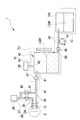
本実施形態の液体貯留装置が設けられる眼科装置1について説明する。眼科装置1は、例えば、白内障硝子体手術に使用されるものである。本実施形態では、詳しくは後述するように、廃液貯留装置61(液体貯留装置)において、タンク42内の廃液LQWの液位を測定しながら、タンク42内に廃液LQWを一時的に貯留させる。そこで、まず、眼科装置1の全体的な構成について説明をした後、廃液貯留装置61について説明する。 The ophthalmic apparatus 1 provided with the liquid storage apparatus of the present embodiment will be described. The ophthalmic apparatus 1 is used, for example, for cataract vitreous surgery. In the present embodiment, as will be described in detail later, the waste liquid LQW is temporarily stored in the tank 42 while measuring the liquid level of the waste liquid LQW in the tank 42 in the waste liquid storage device 61 (liquid storage device). Therefore, first, the overall configuration of the ophthalmic apparatus 1 will be described, and then the waste liquid storage apparatus 61 will be described.

図1と図2に示すように、本実施形態の眼科装置1は、一例として、本体11とカセット12を備えている。本体11は、モニタ21と接続パネル22を備えている。モニタ21に、一例として、手術条件の設定画面や手術装置の駆動結果である手術結果の一覧等が表示される。接続パネル22に、一例として、手術用ハンドピース13のケーブル等が接続される複数のコネクタが設けられている。 As shown in FIGS. 1 and 2, the ophthalmic apparatus 1 of the present embodiment includes a main body 11 and a cassette 12 as an example. The main body 11 includes a monitor 21 and a connection panel 22. As an example, the monitor 21 displays a screen for setting surgical conditions, a list of surgical results that are the driving results of the surgical device, and the like. As an example, the connection panel 22 is provided with a plurality of connectors to which a cable or the like of the surgical handpiece 13 is connected.

本体11は、一例として、白内障手術用などのカセット12が装着される保持ユニット23を側面に備えている。 As an example, the main body 11 is provided with a holding unit 23 on the side surface on which a cassette 12 for cataract surgery or the like is mounted.

本体11は、背面にポール24とアーム24aを備えている。ポール24は、生理食塩水等の灌流液が入れられた灌流瓶26を支持する。アーム24aは、ポール24の上側で灌流瓶26を吊り下げる。ポール24は、制御部14(図3参照)によって駆動機構27(図3参照)が駆動されることで上下する。 The main body 11 is provided with a pole 24 and an arm 24a on the back surface. The pole 24 supports a perfusion bottle 26 containing a perfusion solution such as saline. The arm 24a suspends the perfusion bottle 26 above the pole 24. The pole 24 moves up and down when the drive mechanism 27 (see FIG. 3) is driven by the control unit 14 (see FIG. 3).

本体11は、背面にインターフェイス部を備えている。インターフェイス部は、例えば、手術結果等を電子データとして外部転送するために、LAN,USBストレージデバイス等を介して外部機器(PC)と接続してもよい。 The main body 11 is provided with an interface portion on the back surface. The interface unit may be connected to an external device (PC) via a LAN, a USB storage device, or the like, for example, in order to externally transfer the surgical results or the like as electronic data.

本体11は、フットスイッチ28を備えている。フットスイッチ28は、手術用ハンドピース13の先端部に設けられている可動チップの超音波振動や吸引動作などの各種動作を調整するために用いられてもよい。 The main body 11 includes a foot switch 28. The foot switch 28 may be used to adjust various operations such as ultrasonic vibration and suction operation of the movable tip provided at the tip of the surgical handpiece 13.

本体11は、内部に制御部14(図3参照)を備えている。制御部14は、一例として、眼科装置1の各種動作制御のために用いられる。 The main body 11 includes a control unit 14 (see FIG. 3) inside. The control unit 14 is used, for example, for controlling various operations of the ophthalmic apparatus 1.

図3に示すように、制御部14に、例えば、手術用ハンドピース13、モニタ21、接続パネル22、駆動機構27、フットスイッチ28、吸気部29、廃液吸引部31、記憶部32、インターフェイス部、および各種弁部が接続されている。記憶部32として、例えば、書き換え可能なフラッシュメモリを用いてもよい。記憶部32は、手術を実行するためのプログラム、および本体11の手術動作で取得された各種手術情報を記憶してもよい。 As shown in FIG. 3, the control unit 14, for example, the surgical handpiece 13, the monitor 21, the connection panel 22, the drive mechanism 27, the foot switch 28, the intake unit 29, the waste liquid suction unit 31, the storage unit 32, and the interface unit. , And various valves are connected. As the storage unit 32, for example, a rewritable flash memory may be used. The storage unit 32 may store a program for executing the surgery and various surgical information acquired by the surgical operation of the main body 11.

制御部14は、例えば、記憶部32に記憶されている灌流吸引プログラムを読み出す。制御部14は、例えば、吸気部29の駆動、廃液吸引部31の駆動、および各種弁の駆動を制御するプロセッサとして働く。なお、プロセッサとして、CPU(マイクロプロセッサ)、DSP(デジタル・シグナル・プロセッサ)、PLD(プログラマブル・ロジック・デバイス)等を用いてもよい。 The control unit 14 reads, for example, the perfusion suction program stored in the storage unit 32. The control unit 14 functions as a processor that controls, for example, the drive of the intake unit 29, the drive of the waste liquid suction unit 31, and the drive of various valves. As the processor, a CPU (microprocessor), a DSP (digital signal processor), a PLD (programmable logic device), or the like may be used.

<手術用ハンドピース>
本実施形態の眼科装置1は、手術用ハンドピース13を備えている。眼科装置1は、手術用ハンドピース13の一例として、USハンドピース(超音波ハンドピース)を用いている。USハンドピースは、例えば、白内障によって不透明になり硬化した水晶体核を、先端に設けられた破砕用チップの超音波振動によって乳化吸引除去する。破砕用チップの超音波振動を行うために、手術用ハンドピース13内に設けられた超音波振動子に電力ケーブル33を介して電力供給してもよい。なお、手術用ハンドピース13は、USハンドピースに限るものではない。手術用ハンドピース13として、例えば、I/Aハンドピース16(灌流吸引用ハンドピース)を用いてもよい。本実施形態の手術用ハンドピース13には、電力ケーブル33のほかに、灌流チューブ34と吸引チューブ36が接続されている。灌流チューブ34は、例えば、患者眼Eへ灌流液を流し込むために用いられる。吸引チューブ36は、例えば、患者眼Eから灌流液を含む廃液LQW(液体)を吸い出すために用いられる。
<Surgery handpiece>
The ophthalmic apparatus 1 of the present embodiment includes a surgical handpiece 13. The ophthalmic apparatus 1 uses a US handpiece (ultrasonic handpiece) as an example of the surgical handpiece 13. The US handpiece, for example, emulsifies and sucks and removes a crystalline lens nucleus that has become opaque and hardened due to cataract by ultrasonic vibration of a crushing tip provided at the tip. In order to perform ultrasonic vibration of the crushing chip, electric power may be supplied to the ultrasonic vibrator provided in the surgical handpiece 13 via the power cable 33. The surgical handpiece 13 is not limited to the US handpiece. As the surgical handpiece 13, for example, the I / A handpiece 16 (perfusion suction handpiece) may be used. In addition to the power cable 33, the perfusion tube 34 and the suction tube 36 are connected to the surgical handpiece 13 of the present embodiment. The perfusion tube 34 is used, for example, to pour the perfusate into the patient's eye E. The suction tube 36 is used, for example, to suck out the waste liquid LQW (liquid) containing the perfusate from the patient's eye E.

<供給部>
本実施形態の眼科装置1は、供給部を有している。供給部は、例えば、灌流液を患者眼Eへ供給する。供給部は、一例として、駆動機構27、ポール24、灌流瓶26、灌流チューブ37、灌流チューブ34、灌流弁部38、および手術用ハンドピース13を備えている。供給部は、灌流液が流れる灌流路39を有する。灌流路39は、灌流チューブ34、および灌流チューブ37を含む。前述したように、本実施形態の眼科装置1のポール24には、灌流液が満たされた灌流瓶26が吊り下げられている。ポール24は、制御部14が駆動機構27を駆動することで上下される。ポール24の上下動に伴って、灌流瓶26から流れる灌流液の供給圧が調節される。灌流瓶26からの灌流液は、灌流チューブ37および灌流チューブ34を通過し、術者に把持される手術用ハンドピース13を介して患者眼Eへ灌注される。灌流路39の途中で、灌流路39を流れる灌流液の流出制御が行われる。
<Supply section>
The ophthalmic apparatus 1 of the present embodiment has a supply unit. The supply unit supplies, for example, the perfusate to the patient's eye E. As an example, the supply unit includes a drive mechanism 27, a pole 24, a perfusion bottle 26, a perfusion tube 37, a perfusion tube 34, a perfusion valve portion 38, and a surgical handpiece 13. The supply unit has a perfusion channel 39 through which the perfusate flows. The perfusion channel 39 includes a perfusion tube 34 and a perfusion tube 37. As described above, a perfusion bottle 26 filled with a perfusion solution is suspended from the pole 24 of the ophthalmic apparatus 1 of the present embodiment. The pole 24 is moved up and down by the control unit 14 driving the drive mechanism 27. As the pole 24 moves up and down, the supply pressure of the perfusate flowing from the perfusion bottle 26 is adjusted. The perfusate from the perfusion bottle 26 passes through the perfusion tube 37 and the perfusion tube 34 and is perfused into the patient's eye E via the surgical handpiece 13 gripped by the operator. In the middle of the perfusion channel 39, the outflow control of the perfusate flowing through the perfusion channel 39 is performed.

<吸引部>
本実施形態の眼科装置1は、吸引部を備えている。吸引部は、例えば、吸気部29を用いて、患者眼Eから灌流液を含む廃液LQWを吸引する。吸引部は、一例として、手術用ハンドピース13、吸引チューブ36、廃液路41、タンク42(貯留部)、吸気路43、吸気部29、廃液路44、廃液吸引部31、および廃液バッグ12bを備えている。
<Suction part>
The ophthalmic apparatus 1 of the present embodiment includes a suction unit. The suction unit, for example, uses the intake unit 29 to suck the waste liquid LQW containing the perfusate from the patient's eye E. As an example, the suction part includes a surgical handpiece 13, a suction tube 36, a waste liquid suction part 41, a tank 42 (storage part), an intake passage 43, an intake part 29, a waste liquid passage 44, a waste liquid suction part 31, and a waste liquid bag 12b. I have.

廃液路41は、患者眼Eから吸引した、灌流液を含む廃液LQWが流れる流路である。廃液路41は、吸引チューブ36とタンク42に接続されている。 The waste liquid passage 41 is a flow path through which the waste liquid LQW containing the perfusate liquid sucked from the patient's eye E flows. The waste liquid passage 41 is connected to the suction tube 36 and the tank 42.

本実施形態においては、廃液路41は、貯留弁部47を備えている。制御部14が貯留弁部47を開閉制御することで、貯留弁部47の箇所で廃液路41を閉塞可能となっている。なお、制御部14が放流弁部48を制御して、廃液路41を流れる廃液LQWの流量を調節してもよい。タンク42には、患者眼Eから吸引された廃液LQWが一時的に貯留される。廃液路41と吸気路43は、貯留された廃液LQWの液面よりも上方でタンク42に接続されている。 In the present embodiment, the waste liquid passage 41 includes a storage valve portion 47. By controlling the opening and closing of the storage valve unit 47 by the control unit 14, the waste liquid passage 41 can be closed at the storage valve unit 47. The control unit 14 may control the discharge valve unit 48 to adjust the flow rate of the waste liquid LQW flowing through the waste liquid passage 41. The waste liquid LQW sucked from the patient's eye E is temporarily stored in the tank 42. The waste liquid passage 41 and the intake passage 43 are connected to the tank 42 above the liquid level of the stored waste liquid LQW.

吸気路43は、タンク42と吸気部29に接続されている。吸気部29は、例えば、タンク42内の気体をタンク42の外部へと移すための吸引力を発生させる。制御部14は、例えば、吸気部29の吸気力を調整することができる。本実施形態においては、吸気部29の一例として、ベンチュリポンプを用いている。なお、吸気部29は、例えば、真空ポンプ(真空発生器)であってもよい。吸気部29がタンク42内の気体をタンク42の外部へと移すことで、タンク42内の気体の圧力が下げられる。 The intake passage 43 is connected to the tank 42 and the intake portion 29. The intake unit 29 generates, for example, a suction force for transferring the gas in the tank 42 to the outside of the tank 42. The control unit 14 can adjust the intake force of the intake unit 29, for example. In this embodiment, a Venturi pump is used as an example of the intake unit 29. The intake unit 29 may be, for example, a vacuum pump (vacuum generator). The pressure of the gas in the tank 42 is reduced by the intake unit 29 moving the gas in the tank 42 to the outside of the tank 42.

廃液路44は、タンク42と廃液バッグ12bに接続されている。本実施形態の廃液路44は、貯留される廃液LQWの液面よりも下方でタンク42に接続されている。廃液路44は、放流弁部48を備えている。制御部14が放流弁部48を開閉制御することで、放流弁部48の箇所で廃液路44を閉塞することができる。本実施形態においては、廃液路44の少なくとも一部を弾性部材で形成している。本実施形態の廃液吸引部31は、廃液路44の側方に配置されている。前述した弾性部材を、廃液吸引部31のしごき部材でしごくことで、廃液LQWを吸引する吸引力が発生する。本実施形態では、廃液吸引部31の吸引力を用いて、タンク42に貯留された廃液LQWを廃液バッグ12bへ移す。本実施形態においては、廃液吸引部31の一例として、蠕動ポンプを用いている。廃液吸引部31として、例えば、スクロールポンプ、ベーンポンプ、またはダイアフラムポンプ等を用いてもよい。廃液バッグ12bには、廃液吸引部31が吸引した廃液LQWが溜められる。本実施形態では、廃液バッグ12bに溜められる廃液LQWの液面より上方に、廃液路44が接続される。 The waste liquid passage 44 is connected to the tank 42 and the waste liquid bag 12b. The waste liquid passage 44 of the present embodiment is connected to the tank 42 below the liquid level of the stored waste liquid LQW. The waste liquid passage 44 includes a discharge valve portion 48. By controlling the opening and closing of the discharge valve portion 48 by the control unit 14, the waste liquid passage 44 can be closed at the discharge valve portion 48. In the present embodiment, at least a part of the waste liquid passage 44 is formed of an elastic member. The waste liquid suction unit 31 of the present embodiment is arranged on the side of the waste liquid passage 44. By squeezing the elastic member described above with the ironing member of the waste liquid suction unit 31, a suction force for sucking the waste liquid LQW is generated. In the present embodiment, the suction force of the waste liquid suction unit 31 is used to transfer the waste liquid LQW stored in the tank 42 to the waste liquid bag 12b. In this embodiment, a peristaltic pump is used as an example of the waste liquid suction unit 31. As the waste liquid suction unit 31, for example, a scroll pump, a vane pump, a diaphragm pump, or the like may be used. The waste liquid LQW sucked by the waste liquid suction unit 31 is stored in the waste liquid bag 12b. In the present embodiment, the waste liquid passage 44 is connected above the liquid level of the waste liquid LQW stored in the waste liquid bag 12b.

<吸引モード>
次いで、前述した供給部と吸引部を用いた吸引モードを説明する。本実施形態の吸引モードでは、制御部14の制御によって、灌流弁部38、貯留弁部47、および放流弁部48が開かれ、ベント弁部49が閉じられる。
<Suction mode>
Next, a suction mode using the above-mentioned supply unit and suction unit will be described. In the suction mode of the present embodiment, the perfusion valve portion 38, the storage valve portion 47, and the discharge valve portion 48 are opened and the vent valve portion 49 is closed under the control of the control unit 14.

制御部14の制御によって吸気部29が駆動されると、吸気部29は、吸気路43を介して、タンク42内の気体を吸気する。これにより、タンク42内の気体の圧力が低下するので、廃液LQWは、患者眼Eから廃液路41を介してタンク42へ吸引されて貯留される。制御部14は、タンク42における廃液LQWの貯留量が一定になるように、廃液吸引部31を駆動させる。これにより、タンク42に貯留されている廃液LQWの一部は、廃液バッグ12bへ移される。タンク42に貯留される廃液LQWの液位は、後述する廃液貯留装置61の液位測定部71により測定される。 When the intake unit 29 is driven by the control of the control unit 14, the intake unit 29 takes in the gas in the tank 42 via the intake passage 43. As a result, the pressure of the gas in the tank 42 decreases, so that the waste liquid LQW is sucked into the tank 42 from the patient's eye E through the waste liquid passage 41 and stored. The control unit 14 drives the waste liquid suction unit 31 so that the amount of the waste liquid LQW stored in the tank 42 becomes constant. As a result, a part of the waste liquid LQW stored in the tank 42 is transferred to the waste liquid bag 12b. The liquid level of the waste liquid LQW stored in the tank 42 is measured by the liquid level measuring unit 71 of the waste liquid storage device 61 described later.

<ベント流路>
本実施形態の眼科装置1は、ベント流路51を備えている。ベント流路51は、灌流路39と廃液路41に接続されている。ベント流路51に灌流液を流すことで、患者眼Eからの過剰な吸引を抑制する。ベント流路51は、ベント弁部49を有している。制御部14がベント弁部49を開閉制御することで、ベント流路51に流す灌流液の流量を制御可能である。
<Bent flow path>
The ophthalmic apparatus 1 of the present embodiment includes a vent flow path 51. The vent flow path 51 is connected to the perfusion flow path 39 and the waste liquid channel 41. By flowing the perfusate through the vent flow path 51, excessive suction from the patient's eye E is suppressed. The vent flow path 51 has a vent valve portion 49. By controlling the opening and closing of the vent valve portion 49 by the control unit 14, the flow rate of the perfusate flowing through the vent flow path 51 can be controlled.

<カセット>
本実施形態のカセット12は、カセット本体12aおよび廃液バッグ12bを有する。本実施形態のカセット本体12aには、灌流チューブ34、灌流チューブ37、および吸引チューブ36が接続されている。本実施形態のカセット本体12aは、例えば、廃液路41、廃液路44、および吸気路43を有している。廃液バッグ12bは、カセット本体12aの筐体の外側に配置されている。
<Cassette>
The cassette 12 of the present embodiment has a cassette body 12a and a waste liquid bag 12b. A perfusion tube 34, a perfusion tube 37, and a suction tube 36 are connected to the cassette body 12a of the present embodiment. The cassette body 12a of the present embodiment has, for example, a waste liquid passage 41, a waste liquid passage 44, and an intake passage 43. The waste liquid bag 12b is arranged outside the housing of the cassette body 12a.

<液体貯留装置>
次に、廃液貯留装置61(液体貯留装置)について説明する。図2に示すように、廃液貯留装置61は、タンク42と、吸気路43と、吸気部29と、液位測定部71などにより構成されている。
<Liquid storage device>
Next, the waste liquid storage device 61 (liquid storage device) will be described. As shown in FIG. 2, the waste liquid storage device 61 includes a tank 42, an intake passage 43, an intake unit 29, a liquid level measuring unit 71, and the like.

タンク42は、患者眼Eから吸引される廃液LQWを一時的に貯留させる貯留部である。図2に示すように、タンク42は、廃液バッグ12bの上流側に設けられ、廃液取り入れ口81(液体取り入れ口)と、排気口82と、排液口83を備えている。 The tank 42 is a storage unit for temporarily storing the waste liquid LQW sucked from the patient's eye E. As shown in FIG. 2, the tank 42 is provided on the upstream side of the waste liquid bag 12b, and includes a waste liquid intake port 81 (liquid intake port), an exhaust port 82, and a drainage port 83.

廃液取り入れ口81は、廃液路41に接続しており、廃液路41からタンク42内(詳しくは後述する廃液取り入れ室84内)に廃液LQWを取り入れる部分である。排気口82は、吸気路43に接続しており、タンク42内(詳しくは後述する空気排出室86内)の空気を排出する部分である。排液口83は、廃液路44に接続しており、タンク42内に貯留される廃液LQWを排出する部分である。 The waste liquid intake port 81 is connected to the waste liquid passage 41, and is a portion for taking in the waste liquid LQW from the waste liquid passage 41 into the tank 42 (detailed in the waste liquid intake chamber 84 described later). The exhaust port 82 is connected to the intake passage 43 and is a portion for exhausting air in the tank 42 (detailed in the air discharge chamber 86 described later). The drainage port 83 is connected to the waste liquid passage 44 and is a portion for discharging the waste liquid LQW stored in the tank 42.

液位測定部71は、タンク42内に貯留される廃液LQWの液位(貯留量)を測定する部分である。本実施形態の液位測定部71は、タンク42に設けられた透明な窓42a(図4参照)を介して、タンク42内(詳しくは後述する液位測定室85内)の廃液LQWの液位を測定する。なお、液位測定部71における測定結果は、制御部14(図3参照)に送られる。また、液位測定部71は、例えば、発光部と受光部(例えば、リニアイメージセンサ)により構成されている。 The liquid level measuring unit 71 is a part that measures the liquid level (reservoir amount) of the waste liquid LQW stored in the tank 42. The liquid level measuring unit 71 of the present embodiment passes through a transparent window 42a (see FIG. 4) provided in the tank 42, and is a liquid of waste liquid LQW in the tank 42 (details in the liquid level measuring chamber 85 described later). Measure the position. The measurement result in the liquid level measuring unit 71 is sent to the control unit 14 (see FIG. 3). Further, the liquid level measuring unit 71 is composed of, for example, a light emitting unit and a light receiving unit (for example, a linear image sensor).

このような廃液貯留装置61において、吸気部29による吸引により、吸気路43を介して排気口82からタンク42内の空気が排出され、タンク42内の圧力が低下する。そして、これにより、患者眼Eからの廃液LQWが、吸引チューブ36と廃液路41を介して、廃液取り入れ口81からタンク42内に吸引されて貯留される。また、これと並行して、液位測定部71による廃液LQWの液位の測定結果に基づき、廃液LQWの液位が一定になるように廃液吸引部31の吸引流量が調整されて、廃液LQWが排液口83から廃液路44に排出される。このようにして、廃液バッグ12bの上流側において、吸気部29による吸引により患者眼Eから吸引される廃液LQWを一時的に貯留させるタンク42が設けられている。これにより、患者眼Eから廃液LQWを吸引する応答性を向上させることができる。 In such a waste liquid storage device 61, the air in the tank 42 is discharged from the exhaust port 82 through the intake passage 43 by the suction by the intake unit 29, and the pressure in the tank 42 is reduced. As a result, the waste liquid LQW from the patient's eye E is sucked and stored in the tank 42 from the waste liquid intake port 81 via the suction tube 36 and the waste liquid passage 41. In parallel with this, the suction flow rate of the waste liquid suction unit 31 is adjusted so that the liquid level of the waste liquid LQW becomes constant based on the measurement result of the liquid level of the waste liquid LQW by the liquid level measuring unit 71, and the waste liquid LQW Is discharged from the drainage port 83 to the waste liquid passage 44. In this way, on the upstream side of the waste liquid bag 12b, a tank 42 for temporarily storing the waste liquid LQW sucked from the patient's eye E by suction by the intake unit 29 is provided. Thereby, the responsiveness of sucking the waste liquid LQW from the patient's eye E can be improved.

ここで、吸気部29による吸引によりタンク42内の圧力を下げて患者眼Eから廃液LQWを吸引する応答性をさらに向上させるためには、タンク42の容積を出来るだけ小さくすることが有効な方法の一つである。そして、このようにタンク42の容積を小さくしてタンク42を小型化するにあたっては、廃液LQWがタンク42から溢れて吸気部29に吸い込まれないように、廃液LQWがタンク42から溢れる前に廃液LQWを排液口83から適切に排出させる必要がある。そのため、タンク42内に貯留される廃液LQWの液位を安定して測定することが望まれる。しかしながら、タンク42内に取り入れられる廃液LQWや気泡の影響、すなわち、タンク42内に廃液LQWが取り入れられることによりタンク42内に貯留される廃液LQWの液面が波打ったり、廃液LQWとともにタンク42内に取り入れられる気泡がタンク42内に貯留される廃液LQWの液面付近に溜まるなどの影響により、タンク42内に貯留される廃液LQWの液位を安定して測定できないおそれがある。特に、タンク42を小型化するほど、廃液LQWの液位は、タンク42内に取り入れられる廃液LQWや気泡の影響を受け易くなる。 Here, in order to reduce the pressure in the tank 42 by suction by the intake unit 29 and further improve the responsiveness of sucking the waste liquid LQW from the patient's eye E, it is an effective method to reduce the volume of the tank 42 as much as possible. one of. Then, in reducing the volume of the tank 42 in this way to reduce the size of the tank 42, the waste liquid LQW is prevented from overflowing from the tank 42 and being sucked into the intake unit 29, so that the waste liquid LQW does not overflow from the tank 42. It is necessary to properly discharge the LQW from the drain port 83. Therefore, it is desired to stably measure the liquid level of the waste liquid LQW stored in the tank 42. However, the influence of the waste liquid LQW and air bubbles taken into the tank 42, that is, the liquid level of the waste liquid LQW stored in the tank 42 is wavy due to the waste liquid LQW being taken into the tank 42, and the tank 42 together with the waste liquid LQW. There is a possibility that the liquid level of the waste liquid LQW stored in the tank 42 cannot be measured stably due to the influence of air bubbles taken into the tank 42 accumulating near the liquid level of the waste liquid LQW stored in the tank 42. In particular, the smaller the size of the tank 42, the more easily the liquid level of the waste liquid LQW is affected by the waste liquid LQW and air bubbles taken into the tank 42.

そこで、本実施形態では、タンク42の内部が仕切りにより3つの部屋に分かれている。具体的には、図4に示すように、タンク42は、廃液取り入れ室84(液体取り入れ室)と、液位測定室85と、空気排出室86(気体排出室)と、仕切り87(第1の仕切り)と、仕切り88(第2の仕切り)を備えている。 Therefore, in the present embodiment, the inside of the tank 42 is divided into three rooms by a partition. Specifically, as shown in FIG. 4, the tank 42 includes a waste liquid intake chamber 84 (liquid intake chamber), a liquid level measurement chamber 85, an air discharge chamber 86 (gas discharge chamber), and a partition 87 (first). Partition) and partition 88 (second partition) are provided.

廃液取り入れ室84は、廃液取り入れ口81に接続しており、廃液取り入れ口81から廃液LQWが取り入れられる部屋である。本実施形態では、廃液取り入れ口81は、廃液取り入れ室84内に貯留される廃液LQWの液面よりも上方となる位置に設けられている。 The waste liquid intake room 84 is connected to the waste liquid intake port 81, and is a room in which the waste liquid LQW is taken in from the waste liquid intake port 81. In the present embodiment, the waste liquid intake port 81 is provided at a position above the liquid level of the waste liquid LQW stored in the waste liquid intake chamber 84.

液位測定室85は、液位測定部71(図2参照)により廃液LQWの液位を測定するための部屋である。なお、図4に示す例においては、一例として、液位測定室85に排液口83が設けられている。 The liquid level measuring room 85 is a room for measuring the liquid level of the waste liquid LQW by the liquid level measuring unit 71 (see FIG. 2). In the example shown in FIG. 4, as an example, the liquid level measuring chamber 85 is provided with a drainage port 83.

空気排出室86は、吸気路43を介して吸気部29(図2参照)に接続されており、空気をタンク42内から吸気路43へ排出する部屋である。なお、空気排出室86の上方に、排気口82が設けられている。 The air discharge chamber 86 is connected to the intake portion 29 (see FIG. 2) via the intake passage 43, and is a room for discharging air from the tank 42 to the intake passage 43. An exhaust port 82 is provided above the air discharge chamber 86.

仕切り87は、廃液取り入れ室84と液位測定室85とを分けている。仕切り88は、液位測定室85と空気排出室86とを分けている。 The partition 87 separates the waste liquid intake chamber 84 and the liquid level measurement chamber 85. The partition 88 separates the liquid level measurement chamber 85 and the air discharge chamber 86.

このように本実施形態では、タンク42は、液位測定室85が廃液取り入れ室84と分けられている。これにより、液位測定室85内に貯留される廃液LQWは、廃液取り入れ室84内に取り入れられる廃液LQWや気泡の影響を受け難くなる。すなわち、廃液取り入れ室84と液位測定室85が仕切り87により分けられているので、廃液取り入れ室84内に廃液LQWが取り入れられることにより廃液取り入れ室84内に貯留される廃液LQWの液面が波打ってもその液面の変動は仕切り87に遮られるため液位測定室85内に伝わり難く、また、廃液取り入れ室84内に廃液LQWとともに取り入れられた気泡は仕切り87に遮られるため液位測定室85内へ移動し難い。そのため、液位測定室85内に貯留される廃液LQWの液位が安定するので、液位測定部71により安定した廃液LQWの液位の測定が可能となる。 As described above, in the present embodiment, in the tank 42, the liquid level measuring chamber 85 is separated from the waste liquid taking-in chamber 84. As a result, the waste liquid LQW stored in the liquid level measuring chamber 85 is less susceptible to the influence of the waste liquid LQW and air bubbles taken into the waste liquid intake chamber 84. That is, since the waste liquid intake chamber 84 and the liquid level measurement chamber 85 are separated by the partition 87, the liquid level of the waste liquid LQW stored in the waste liquid intake chamber 84 is raised by taking the waste liquid LQW into the waste liquid intake chamber 84. Even if it undulates, the fluctuation of the liquid level is blocked by the partition 87, so that it is difficult to be transmitted to the liquid level measurement chamber 85, and the bubbles taken into the waste liquid intake chamber 84 together with the waste liquid LQW are blocked by the partition 87, so the liquid level. Difficult to move into the measurement chamber 85. Therefore, since the liquid level of the waste liquid LQW stored in the liquid level measuring chamber 85 is stable, the liquid level measuring unit 71 can measure the liquid level of the waste liquid LQW in a stable manner.

また、タンク42は、液位測定室85が空気排出室86と分けられている。これにより、液位測定室85内に貯留される廃液LQWは、空気排出室86内から排出される空気の影響を受け難くなる。すなわち、液位測定室85と空気排出室86が仕切り88により分けられているので、空気排出室86内から空気が排出されることにより生じる空気排出室86内の空気の流れは、(後述する上方連通部93の部分を除いて)仕切り88により遮られるため、空気排出室86から直接的に液位測定室85に伝わり難い。そのため、液位測定室85内に貯留される廃液LQWの液位が安定するので、液位測定部71による安定した液位測定が可能となる。 Further, in the tank 42, the liquid level measurement chamber 85 is separated from the air discharge chamber 86. As a result, the waste liquid LQW stored in the liquid level measurement chamber 85 is less likely to be affected by the air discharged from the air discharge chamber 86. That is, since the liquid level measurement chamber 85 and the air discharge chamber 86 are separated by the partition 88, the air flow in the air discharge chamber 86 caused by the air being discharged from the air discharge chamber 86 will be (described later). Since it is blocked by the partition 88 (except for the portion of the upper communication portion 93), it is difficult for the air discharge chamber 86 to directly transmit to the liquid level measurement chamber 85. Therefore, since the liquid level of the waste liquid LQW stored in the liquid level measuring chamber 85 is stable, stable liquid level measurement by the liquid level measuring unit 71 becomes possible.

このように本実施形態では、タンク42の内部が仕切り87と仕切り88により廃液取り入れ室84と液位測定室85と空気排出室86とからなる3つの部屋に分けられているが、廃液取り入れ室84と液位測定室85と空気排出室86とを互いに一部連通させている。すなわち、廃液取り入れ室84と液位測定室85と空気排出室86は、3つの半独立した部屋であって完全に独立しておらず、タンク42の上下部分でつながっている。そして、タンク42の上方に各室間を移動する空気の通り道が形成され、タンク42の下方に各室間を移動する廃液LQWの通り道が形成されている。 As described above, in the present embodiment, the inside of the tank 42 is divided into three rooms by the partition 87 and the partition 88, which are the waste liquid intake room 84, the liquid level measurement room 85, and the air discharge room 86. The 84, the liquid level measurement chamber 85, and the air discharge chamber 86 are partially communicated with each other. That is, the waste liquid intake chamber 84, the liquid level measurement chamber 85, and the air discharge chamber 86 are three semi-independent chambers that are not completely independent and are connected by the upper and lower portions of the tank 42. An air passage that moves between the chambers is formed above the tank 42, and a waste liquid LQW passage that moves between the chambers is formed below the tank 42.

具体的には、タンク42の上方に形成される空気の通り道として、仕切り87は上方連通部91(第1の上方連通部)を備え、仕切り88は上方連通部93(第2の上方連通部)を備えている。 Specifically, as an air passage formed above the tank 42, the partition 87 is provided with an upper communication portion 91 (first upper communication portion), and the partition 88 is an upper communication portion 93 (second upper communication portion). ) Is provided.

上方連通部91は、廃液取り入れ室84内に貯留される廃液LQWの液面よりも上方となる位置に形成され、廃液取り入れ室84と液位測定室85とを連通させている。このように、廃液取り入れ室84と液位測定室85は上方連通部91を介して一部連通しており、廃液取り入れ室84内の空気を上方連通部91を介して液位測定室85内に流すことができる。なお、図4に示す例では、上方連通部91は、廃液取り入れ室84の最上部の位置に形成されている。 The upper communication portion 91 is formed at a position above the liquid level of the waste liquid LQW stored in the waste liquid intake chamber 84, and communicates the waste liquid intake chamber 84 and the liquid level measurement chamber 85. In this way, the waste liquid intake chamber 84 and the liquid level measurement chamber 85 partially communicate with each other via the upper communication portion 91, and the air in the waste liquid intake chamber 84 is passed through the upper communication portion 91 into the liquid level measurement chamber 85. Can be flushed to. In the example shown in FIG. 4, the upper communication portion 91 is formed at the uppermost position of the waste liquid intake chamber 84.

上方連通部93は、液位測定室85内に貯留される廃液LQWの液面よりも上方となる位置に形成され、液位測定室85と空気排出室86とを連通させている。このように、液位測定室85と空気排出室86は上方連通部93を介して一部連通しており、液位測定室85内の空気を上方連通部93を介して空気排出室86内に流すことができる。なお、図4に示す例では、上方連通部93は、液位測定室85の最上部の位置に形成されている。 The upper communication portion 93 is formed at a position above the liquid level of the waste liquid LQW stored in the liquid level measurement chamber 85, and communicates the liquid level measurement chamber 85 and the air discharge chamber 86. In this way, the liquid level measurement chamber 85 and the air discharge chamber 86 are partially communicated with each other via the upper communication portion 93, and the air in the liquid level measurement chamber 85 is passed through the upper communication portion 93 into the air discharge chamber 86. Can be flushed to. In the example shown in FIG. 4, the upper communication portion 93 is formed at the uppermost position of the liquid level measuring chamber 85.

以上のようにして、タンク42の上方に各室間を移動する空気の通り道が形成されているので、吸気部29による吸引によりタンク42内の圧力を低下させて、患者眼Eから廃液LQWをタンク42内に吸引して貯留させることができる。 As described above, since the air passage that moves between the chambers is formed above the tank 42, the pressure in the tank 42 is reduced by suction by the intake unit 29, and the waste liquid LQW is discharged from the patient's eye E. It can be sucked and stored in the tank 42.

また、タンク42の下方に形成される廃液LQWの通り道として、仕切り87は下方連通部92(第1の下方連通部)を備え、仕切り88は下方連通部94(第2の下方連通部)を備えている。 Further, as a passage for the waste liquid LQW formed below the tank 42, the partition 87 is provided with a lower communication portion 92 (first lower communication portion), and the partition 88 is provided with a lower communication portion 94 (second lower communication portion). I have.

下方連通部92は、廃液取り入れ室84内に貯留される廃液LQWの液面よりも下方となる位置に形成され、廃液取り入れ室84と液位測定室85とを連通させている。このように、廃液取り入れ室84と液位測定室85は下方連通部92を介して一部連通しており、廃液取り入れ室84内の廃液LQWを下方連通部92を介して液位測定室85内に流すことができる。なお、図4に示す例では、下方連通部92は、廃液取り入れ室84の最下部の位置に形成されている。 The lower communication portion 92 is formed at a position below the liquid level of the waste liquid LQW stored in the waste liquid intake chamber 84, and communicates the waste liquid intake chamber 84 and the liquid level measurement chamber 85. As described above, the waste liquid intake chamber 84 and the liquid level measurement chamber 85 partially communicate with each other via the lower communication portion 92, and the waste liquid LQW in the waste liquid intake chamber 84 is partially communicated via the lower communication portion 92 in the liquid level measurement chamber 85. Can be flushed inside. In the example shown in FIG. 4, the lower communication portion 92 is formed at the lowermost position of the waste liquid intake chamber 84.

下方連通部94は、液位測定室85内に貯留される廃液LQWの液面よりも下方となる位置に形成され、液位測定室85と空気排出室86とを連通させている。このように、液位測定室85と空気排出室86は下方連通部94を介して一部連通しており、液位測定室85と空気排出室86との間で下方連通部94を介して廃液LQWを移動させることができる。なお、仮に上方連通部93から空気排出室86内に入り込んでしまった廃液LQWを、下方連通部94を介して、液位測定室85内へ移動させることもできる。なお、図4に示す例では、下方連通部94は、液位測定室85の最下部の位置に形成されている。 The lower communication portion 94 is formed at a position below the liquid level of the waste liquid LQW stored in the liquid level measurement chamber 85, and communicates the liquid level measurement chamber 85 and the air discharge chamber 86. As described above, the liquid level measuring chamber 85 and the air discharge chamber 86 partially communicate with each other via the lower communication portion 94, and the liquid level measuring chamber 85 and the air discharge chamber 86 communicate with each other via the lower communication portion 94. The waste liquid LQW can be moved. It is also possible to move the waste liquid LQW that has entered the air discharge chamber 86 from the upper communication portion 93 into the liquid level measurement chamber 85 via the lower communication portion 94. In the example shown in FIG. 4, the lower communication portion 94 is formed at the lowermost position of the liquid level measuring chamber 85.

以上のようにして、タンク42の下方に廃液LQWの通り道が形成されているので、患者眼Eから吸引される廃液LQWを廃液取り入れ室84内から液位測定室85と空気排出室86へ流して、排液口83から排出させることができる。 Since the path of the waste liquid LQW is formed below the tank 42 as described above, the waste liquid LQW sucked from the patient's eye E is allowed to flow from the waste liquid intake chamber 84 to the liquid level measurement chamber 85 and the air discharge chamber 86. Therefore, it can be discharged from the drain port 83.

このように本実施形態では、廃液取り入れ室84と液位測定室85と空気排出室86とが互いに一部連通していることにより、廃液貯留装置61において、吸気部29による吸引により患者眼Eから吸引される廃液LQWをタンク42内に一時的に貯留させる機能が確保されている。 As described above, in the present embodiment, the waste liquid intake chamber 84, the liquid level measurement chamber 85, and the air discharge chamber 86 partially communicate with each other, so that the waste liquid storage device 61 is sucked by the intake unit 29 to allow the patient's eye E. The function of temporarily storing the waste liquid LQW sucked from the tank 42 in the tank 42 is secured.

また、本実施形態では、廃液取り入れ口81は、廃液取り入れ室84内に貯留される廃液LQWの液面よりも上方となる位置に設けられている。これにより、廃液取り入れ口81から廃液LQWとともに取り入れられる気泡は、廃液取り入れ室84内に貯留される廃液LQWに混ざる前に廃液LQWから分離され易くなるので、廃液取り入れ室84内に貯留される廃液LQWに混ざり難くなる。そのため、下方連通部92を介して廃液取り入れ室84に連通する液位測定室85内に貯留される廃液LQWにも、気泡が混ざり難くなる。したがって、液位測定室85内に貯留される廃液LQWの液位が安定するので、液位測定部71により安定した廃液LQWの液位の測定が可能となる。 Further, in the present embodiment, the waste liquid intake port 81 is provided at a position above the liquid level of the waste liquid LQW stored in the waste liquid intake chamber 84. As a result, the bubbles taken in together with the waste liquid LQW from the waste liquid intake port 81 are easily separated from the waste liquid LQW before being mixed with the waste liquid LQW stored in the waste liquid intake chamber 84, so that the waste liquid stored in the waste liquid intake chamber 84 is easily separated. It becomes difficult to mix with LQW. Therefore, it becomes difficult for air bubbles to be mixed in the waste liquid LQW stored in the liquid level measurement chamber 85 communicating with the waste liquid intake chamber 84 via the lower communication portion 92. Therefore, since the liquid level of the waste liquid LQW stored in the liquid level measuring chamber 85 is stable, the liquid level measuring unit 71 can measure the liquid level of the waste liquid LQW in a stable manner.

さらに、廃液取り入れ口81は、当該廃液取り入れ口81の軸線Sが液体取り入れ室84の内壁面84aに向かうようにして、筒状のタンク42の軸線に対して傾いて形成されている。これにより、液体取り入れ口81から取り入れられた廃液LQWを廃液取り入れ室84の内壁面84aへ案内して流すことができるので、廃液LQWに含まれる気泡を廃液LQWから分離させて、廃液LQWのみをタンク42内に貯留させ易くなる。このようにして、タンク42においては、廃液取り入れ口81から取り入れられた廃液LQWを廃液取り入れ室84の内壁面84aへ案内して流す廃液案内構造(液体案内構造)が形成されている。 Further, the waste liquid intake port 81 is formed so as to be inclined with respect to the axis of the tubular tank 42 so that the axis S of the waste liquid intake port 81 faces the inner wall surface 84a of the liquid intake chamber 84. As a result, the waste liquid LQW taken in from the liquid intake port 81 can be guided to the inner wall surface 84a of the waste liquid intake chamber 84 and flowed, so that the bubbles contained in the waste liquid LQW are separated from the waste liquid LQW, and only the waste liquid LQW is separated. It becomes easy to store in the tank 42. In this way, in the tank 42, a waste liquid guide structure (liquid guide structure) is formed in which the waste liquid LQW taken in from the waste liquid intake port 81 is guided to the inner wall surface 84a of the waste liquid intake chamber 84 and flows.

また、本実施形態では、上方連通部91と上方連通部93は、仕切り87と仕切り88が配列される方向から見たときに、重ならない位置、または、一部のみ重なる位置に形成されている。例えば、図4に示す例においては、上方連通部91は図面の奥行側の位置に形成され、上方連通部93は図面の手前側の位置に形成されており、上方連通部91と上方連通部93は、仕切り87と仕切り88が配列される方向から見たときに、重ならない位置に形成されている。これにより、廃液取り入れ口81から廃液取り入れ室84内へ取り入れられる廃液LQWが、上方連通部91と上方連通部93を介して空気排出室86内へ入り込み難くなる。そのため、空気排出室86に接続する吸気部29に廃液LQWが吸引され難くなる。 Further, in the present embodiment, the upper communication portion 91 and the upper communication portion 93 are formed at positions where they do not overlap or only partially overlap when viewed from the direction in which the partition 87 and the partition 88 are arranged. .. For example, in the example shown in FIG. 4, the upper communication portion 91 is formed at a position on the depth side of the drawing, the upper communication portion 93 is formed at a position on the front side of the drawing, and the upper communication portion 91 and the upper communication portion 91 are formed. The 93 is formed at a position where the partition 87 and the partition 88 do not overlap when viewed from the direction in which the partition 87 is arranged. As a result, it becomes difficult for the waste liquid LQW taken into the waste liquid intake chamber 84 from the waste liquid intake port 81 to enter the air discharge chamber 86 via the upper communication portion 91 and the upper communication portion 93. Therefore, it becomes difficult for the waste liquid LQW to be sucked into the intake unit 29 connected to the air discharge chamber 86.

以上のように本実施形態によれば、タンク42は、廃液取り入れ室84と、液位測定室85と、廃液取り入れ室84と液位測定室85とを一部連通させながら分ける仕切り87を備えている。また、廃液取り入れ口81は、廃液取り入れ室84内に貯留される廃液LQWの液面よりも上方となる位置に設けられている。 As described above, according to the present embodiment, the tank 42 includes a partition 87 that divides the waste liquid intake chamber 84, the liquid level measurement chamber 85, and the waste liquid intake chamber 84 and the liquid level measurement chamber 85 while partially communicating with each other. ing. Further, the waste liquid intake port 81 is provided at a position above the liquid level of the waste liquid LQW stored in the waste liquid intake chamber 84.

これにより、液位測定室85内に貯留される廃液LQWは、廃液取り入れ室84内に取り入れられる廃液LQWの影響を受け難くなる。また、廃液取り入れ口81から廃液LQWとともに取り入れられる気泡は、液位測定室85内に貯留される廃液LQWに混ざり難くなる。そのため、液位測定室85内に貯留される廃液LQWの液位が安定する。したがって、タンク42を小型化しながら、タンク42内の廃液LQWの液位を安定して測定できる。ゆえに、廃液LQWの液位の測定結果に基づき廃液LQWの液位が一定になるように廃液吸引部31の吸引流量を調整して、廃液LQWを排液口83から廃液路44に排出させることができる。以上のようなことから、タンク42を出来るだけ小型化して、吸気部29による吸引により患者眼Eから廃液LQWを吸引する応答性を向上させることができる。 As a result, the waste liquid LQW stored in the liquid level measuring chamber 85 is less likely to be affected by the waste liquid LQW taken in the waste liquid intake chamber 84. Further, the bubbles taken in together with the waste liquid LQW from the waste liquid intake port 81 are less likely to be mixed with the waste liquid LQW stored in the liquid level measuring chamber 85. Therefore, the liquid level of the waste liquid LQW stored in the liquid level measuring chamber 85 is stable. Therefore, the liquid level of the waste liquid LQW in the tank 42 can be stably measured while the tank 42 is miniaturized. Therefore, the suction flow rate of the waste liquid suction unit 31 is adjusted so that the liquid level of the waste liquid LQW becomes constant based on the measurement result of the liquid level of the waste liquid LQW, and the waste liquid LQW is discharged from the drain port 83 to the waste liquid passage 44. Can be done. From the above, the tank 42 can be made as small as possible, and the responsiveness of sucking the waste liquid LQW from the patient's eye E by suction by the intake unit 29 can be improved.

また、本実施形態によれば、タンク42は、空気排出室86と、液位測定室85と空気排出室86とを一部連通させながら分ける仕切り88と、を備える。これにより、液位測定室85内に貯留される廃液LQWは、空気排出室86内から排出される空気の影響を受け難くなる。そのため、液位測定室85内に貯留される廃液LQWの液位が安定する。したがって、タンク42を小型化しながら、タンク42内の廃液LQWの液位を安定して測定できる。 Further, according to the present embodiment, the tank 42 includes an air discharge chamber 86, and a partition 88 that divides the liquid level measurement chamber 85 and the air discharge chamber 86 while partially communicating with each other. As a result, the waste liquid LQW stored in the liquid level measurement chamber 85 is less likely to be affected by the air discharged from the air discharge chamber 86. Therefore, the liquid level of the waste liquid LQW stored in the liquid level measuring chamber 85 is stable. Therefore, the liquid level of the waste liquid LQW in the tank 42 can be stably measured while the tank 42 is miniaturized.

また、本実施形態によれば、仕切り87は上方連通部91を備え、仕切り88は上方連通部93を備えている。これにより、廃液取り入れ室84内の空気を上方連通部91と上方連通部93を介して空気排出室86内から排出させることができる。また、液位測定室85内の空気を上方連通部93を介して空気排出室86内から排出させることができる。そのため、吸気部29によりタンク42内の空気を吸引してタンク42内の圧力を下げることにより、廃液LQWをタンク42内に取り入れることができる。 Further, according to the present embodiment, the partition 87 includes the upper communication portion 91, and the partition 88 includes the upper communication portion 93. As a result, the air in the waste liquid intake chamber 84 can be discharged from the air discharge chamber 86 via the upper communication portion 91 and the upper communication portion 93. Further, the air in the liquid level measuring chamber 85 can be discharged from the air discharge chamber 86 via the upper communication portion 93. Therefore, the waste liquid LQW can be taken into the tank 42 by sucking the air in the tank 42 by the intake unit 29 and lowering the pressure in the tank 42.

また、本実施形態によれば、上方連通部91と上方連通部93は、仕切り87と仕切り88が配列される方向から見たときに、重ならない位置、または、一部のみ重なる位置に形成されている。これにより、廃液取り入れ室84内に取り入れられる廃液LQWが、上方連通部91と上方連通部93を介して空気排出室86内へ入り込み難くなる。そのため、空気排出室86に接続する吸気部29に廃液LQWが吸引され難くなる。 Further, according to the present embodiment, the upper communication portion 91 and the upper communication portion 93 are formed at positions where the partition 87 and the partition 88 do not overlap or only partially overlap when viewed from the direction in which the partition 87 and the partition 88 are arranged. ing. As a result, the waste liquid LQW taken into the waste liquid intake chamber 84 is less likely to enter the air discharge chamber 86 via the upper communication portion 91 and the upper communication portion 93. Therefore, it becomes difficult for the waste liquid LQW to be sucked into the intake unit 29 connected to the air discharge chamber 86.

また、本実施形態によれば、液体取り入れ口81は、当該液体取り入れ口81の軸線Sが液体取り入れ室84の内壁面84aに向かうようにして、傾いて形成されている。これにより、廃液LQWを廃液取り入れ室84の内壁面84aへ案内して流すことができるので、廃液LQWに含まれる気泡を廃液LQWから分離させて、廃液LQWのみをタンク42内に貯留させ易くなる。なお、本実施形態で開示する液体取り入れ口81の態様は一例に過ぎず、液体取り入れ口81の軸線Sは、傾いていなくてもよく、廃液LQWを廃液取り入れ室84の内壁面84aへ案内して流すことができるのであれば、例えば水平であってもよい。 Further, according to the present embodiment, the liquid intake port 81 is formed so as to be inclined so that the axis S of the liquid intake port 81 faces the inner wall surface 84a of the liquid intake chamber 84. As a result, the waste liquid LQW can be guided to the inner wall surface 84a of the waste liquid intake chamber 84 and flowed, so that the bubbles contained in the waste liquid LQW can be separated from the waste liquid LQW, and only the waste liquid LQW can be easily stored in the tank 42. .. The aspect of the liquid intake port 81 disclosed in the present embodiment is only an example, and the axis S of the liquid intake port 81 does not have to be tilted, and guides the waste liquid LQW to the inner wall surface 84a of the waste liquid intake chamber 84. It may be horizontal, for example, as long as it can be flushed.

また、本実施形態によれば、仕切り87は、下方連通部92を備えている。これにより、廃液取り入れ室84内に取り入れられた廃液LQWを、下方連通部92を介して、液位測定室85内へ流すことができる。 Further, according to the present embodiment, the partition 87 includes a lower communication portion 92. As a result, the waste liquid LQW taken into the waste liquid intake chamber 84 can be flowed into the liquid level measurement chamber 85 via the lower communication portion 92.

なお、変形例として、タンク42は、仕切り88を有さず、液位測定室85と空気排出室86とが一体的に形成されて1つの部屋となっていてもよい。 As a modification, the tank 42 may not have a partition 88, and the liquid level measurement chamber 85 and the air discharge chamber 86 may be integrally formed into one chamber.

また、排液口83は、タンク42内の3つの部屋のいずれかに設けられていればよく、廃液取り入れ室84または空気排出室86に設けられていてもよい。また、タンク42は、廃液取り入れ口81から取り入れられた廃液LQWを廃液取り入れ室84の内壁面84aへ案内して流す廃液案内構造の変形例として、廃液取り入れ口81と廃液取り入れ室84の内壁面84aとを繋ぐ接続部を有していてもよい。 Further, the drainage port 83 may be provided in any of the three chambers in the tank 42, and may be provided in the waste liquid intake chamber 84 or the air discharge chamber 86. Further, as a modified example of the waste liquid guidance structure in which the waste liquid LQW taken in from the waste liquid intake port 81 is guided to the inner wall surface 84a of the waste liquid intake chamber 84 and flowed, the tank 42 is an inner wall surface of the waste liquid intake port 81 and the waste liquid intake chamber 84. It may have a connecting portion for connecting to 84a.

上記においては、眼科装置1は例えば白内障手術に使用されるものであるとして説明したが、眼科装置1は硝子体手術にも使用することができる。 In the above, the ophthalmic apparatus 1 has been described as being used for cataract surgery, for example, but the ophthalmic apparatus 1 can also be used for vitreous surgery.

なお、上記した実施の形態は単なる例示にすぎず、本開示を何ら限定するものではなく、その要旨を逸脱しない範囲内で種々の改良、変形が可能であることはもちろんである。 It should be noted that the above-described embodiment is merely an example and does not limit the present disclosure in any way, and it goes without saying that various improvements and modifications can be made without departing from the gist thereof.

例えば、タンク42は、廃液取り入れ室84と液位測定室85と空気排出室86の他に、廃液LQWを排出するための廃液排出室(液体を排出するための液体排出室)を備えてもよい。このとき、排液口83は、廃液排出室に設けられている。また、タンク42は、液位測定室85と廃液排出室とを一部連通させながら分ける第3の仕切りを備えている。なお、第3の仕切りは、少なくとも、液位測定室85内に貯留される廃液LQWの液面よりも下方となる位置にて液位測定室85と廃液排出室とを連通させる下方連通部(第3の下方連通部)を備えている。これにより、液位測定室85の廃液LQWを、下方連通部を介して、廃液排出室内へ流すことができる。 For example, the tank 42 may include a waste liquid discharge chamber (liquid discharge chamber for discharging the liquid) for discharging the waste liquid LQW in addition to the waste liquid intake chamber 84, the liquid level measurement chamber 85, and the air discharge chamber 86. Good. At this time, the drainage port 83 is provided in the waste liquid discharge chamber. Further, the tank 42 is provided with a third partition that separates the liquid level measuring chamber 85 and the waste liquid discharging chamber while partially communicating with each other. The third partition is a lower communication portion (a lower communication portion) that communicates the liquid level measurement chamber 85 and the waste liquid discharge chamber at least at a position below the liquid level of the waste liquid LQW stored in the liquid level measurement chamber 85. It has a third lower communication section). As a result, the waste liquid LQW of the liquid level measurement chamber 85 can flow into the waste liquid discharge chamber via the lower communication portion.

1 眼科装置
11 本体
12 カセット
12a カセット本体
12b 廃液バッグ
29 吸気部
42 タンク
42a 窓
43 吸気路
61 廃液貯留装置
71 液位測定部
81 廃液取り入れ口
82 排気口
83 排液口
84 廃液取り入れ室
84a 内壁面
85 液位測定室
86 空気排出室
87 仕切り
88 仕切り
91 上方連通部
92 下方連通部
93 上方連通部
LQW 廃液
1 Ophthalmology device 11 Main body 12 Cassette 12a Cassette main body 12b Waste liquid bag 29 Intake unit 42 Tank 42a Window 43 Intake passage 61 Waste liquid storage device 71 Liquid level measurement unit 81 Waste liquid intake port 82 Exhaust port 83 Drainage port 84 Waste liquid intake room 84a Inner wall surface 85 Liquid level measurement chamber 86 Air discharge chamber 87 Partition 88 Partition 91 Upper communication part 92 Lower communication part 93 Upper communication part LQW Waste liquid

Claims (1)

患者眼から吸引される液体が貯留される貯留部と、
前記貯留部内に前記液体を取り入れるために前記貯留部内の気体を吸引して前記貯留部内の圧力を下げる吸気部と、
前記貯留部内に貯留される前記液体の液位を測定する液位測定部と、を有し、
前記貯留部は、前記液体を取り入れる液体取り入れ口と、前記液体取り入れ口から前記液体が取り入れられる液体取り入れ室と、前記液位測定部により前記液体の液位を測定するための液位測定室と、前記液体取り入れ室と前記液位測定室とを一部連通させながら分ける第1の仕切りと、前記貯留部内に貯留される前記液体を排出する排液口と、を備え、
前記液体取り入れ口は、前記液体取り入れ室内に貯留される前記液体の液面よりも上方となる位置に設けられ
前記貯留部は、前記吸気部に接続され前記気体を排出するための気体排出室と、前記液位測定室と前記気体排出室とを一部連通させながら分ける第2の仕切りと、を備え、
前記第1の仕切りは、前記液体取り入れ室内に貯留される前記液体の液面よりも上方となる位置にて前記液体取り入れ室と前記液位測定室とを連通させる第1の上方連通部を備え、
前記第2の仕切りは、前記液位測定室内に貯留される前記液体の液面よりも上方となる位置にて前記液位測定室と前記気体排出室とを連通させる第2の上方連通部を備え、
前記第1の仕切りは、前記液体取り入れ室内に貯留される前記液体の液面よりも下方となる位置にて前記液体取り入れ室と前記液位測定室とを連通させる下方連通部を備え、
前記第1の仕切りまたは前記第2の仕切りにより、前記液体取り入れ室と前記気体排出室が前記下方連通部よりも上方となる位置にて分けられており、
前記液位測定室は前記液体取り入れ室と前記気体排出室との間に挟まれるようにして形成され、
前記液体取り入れ室と前記液位測定室との間に前記第1の仕切りが形成され、
前記液位測定室と前記気体排出室との間に前記第2の仕切りが形成され、
前記第1の仕切りと前記第2の仕切りは、各々、前記貯留部の最下部から最上部まで延びるように形成され、
前記液体取り入れ室と前記気体排出室は、前記第1の仕切りと前記第2の仕切りにより分けられ、
前記第1の上方連通部と前記第2の上方連通部は、前記第1の仕切りと前記第2の仕切りが配列される方向から見たときに、重ならない位置、または、一部のみ重なる位置に形成されていること、
を特徴とする液体貯留装置。
A reservoir where the liquid sucked from the patient's eye is stored,
An intake unit that sucks gas in the storage unit to reduce the pressure in the storage unit in order to take in the liquid into the storage unit.
It has a liquid level measuring unit for measuring the liquid level of the liquid stored in the storage unit, and has a liquid level measuring unit.
The storage unit includes a liquid intake port for taking in the liquid, a liquid intake chamber for taking in the liquid from the liquid intake port, and a liquid level measuring chamber for measuring the liquid level of the liquid by the liquid level measuring unit. A first partition that separates the liquid intake chamber and the liquid level measurement chamber while partially communicating with each other, and a drainage port for discharging the liquid stored in the storage portion are provided.
The liquid intake port is provided at a position above the liquid level of the liquid stored in the liquid intake chamber .
The storage unit includes a gas discharge chamber connected to the intake unit for discharging the gas, and a second partition for separating the liquid level measurement chamber and the gas discharge chamber while partially communicating with each other.
The first partition includes a first upper communication portion that communicates the liquid intake chamber and the liquid level measuring chamber at a position above the liquid level of the liquid stored in the liquid intake chamber. ,
The second partition has a second upper communication portion that communicates the liquid level measurement chamber and the gas discharge chamber at a position above the liquid level of the liquid stored in the liquid level measurement chamber. Prepare,
The first partition includes a lower communication portion that communicates the liquid intake chamber and the liquid level measurement chamber at a position below the liquid level of the liquid stored in the liquid intake chamber.
The liquid intake chamber and the gas discharge chamber are separated by the first partition or the second partition at a position above the lower communication portion.
The liquid level measuring chamber is formed so as to be sandwiched between the liquid intake chamber and the gas discharge chamber.
The first partition is formed between the liquid intake chamber and the liquid level measurement chamber.
The second partition is formed between the liquid level measuring chamber and the gas discharging chamber.
The first partition and the second partition are each formed so as to extend from the bottom to the top of the reservoir.
The liquid intake chamber and the gas discharge chamber are separated by the first partition and the second partition.
The first upper communication portion and the second upper communication portion are located at positions where they do not overlap or only partially overlap when viewed from the direction in which the first partition and the second partition are arranged. Being formed in
A liquid storage device characterized by.
JP2016109841A 2016-06-01 2016-06-01 Liquid storage device Active JP6801235B2 (en)

Priority Applications (1)

Application Number Priority Date Filing Date Title
JP2016109841A JP6801235B2 (en) 2016-06-01 2016-06-01 Liquid storage device

Applications Claiming Priority (1)

Application Number Priority Date Filing Date Title
JP2016109841A JP6801235B2 (en) 2016-06-01 2016-06-01 Liquid storage device

Publications (3)

Publication Number Publication Date
JP2017213250A JP2017213250A (en) 2017-12-07
JP2017213250A5 JP2017213250A5 (en) 2019-05-16
JP6801235B2 true JP6801235B2 (en) 2020-12-16

Family

ID=60576020

Family Applications (1)

Application Number Title Priority Date Filing Date
JP2016109841A Active JP6801235B2 (en) 2016-06-01 2016-06-01 Liquid storage device

Country Status (1)

Country Link
JP (1) JP6801235B2 (en)

Families Citing this family (4)

* Cited by examiner, † Cited by third party
Publication number Priority date Publication date Assignee Title
JP7247624B2 (en) * 2019-02-12 2023-03-29 セイコーエプソン株式会社 printer
JP2021146534A (en) 2020-03-17 2021-09-27 セイコーエプソン株式会社 Printing device
KR102575901B1 (en) * 2023-07-06 2023-09-07 주식회사 한중엔시에스 leak detection device
KR102596479B1 (en) * 2023-07-10 2023-10-31 주식회사 한중엔시에스 Method for leak detection

Also Published As

Publication number Publication date
JP2017213250A (en) 2017-12-07

Similar Documents

Publication Publication Date Title
JP6801235B2 (en) Liquid storage device
ES2356561T3 (en) SURGICAL CASTLE FOR INTRAOCULAR PRESSURE CONTROL.
TWI401068B (en) Surgical cassette with multi area fluid chamber
ES2347834T3 (en) REFLUX CONTROL IN A MICROQUIRURGICAL SYSTEM.
ES2329175T3 (en) TEST PROCEDURE OF A SURGICAL SYSTEM.
CA2423749C (en) Liquid venting surgical system
TWI392484B (en) Apparatus for priming an aspiration circuit of a microsurgical system
EP1779878A1 (en) Fluid pressure sensing chamber
CN108309558A (en) The mobile valve components of the alternative in suction and perfusion circuit
ES2610224T3 (en) Irrigation / aspiration system, cartridge, pump unit, surgical machine and control method
AU2007227230B2 (en) Surgical cassette with bubble breaking structure
JP3961304B2 (en) Perfusion suction device
JP6464671B2 (en) Perfusion suction device
CA2422019A1 (en) Liquid venting surgical cassette
EP3300704B1 (en) Ophthalmic apparatus
JP6273153B2 (en) Circulating body cavity fluid perfusion system and method of operating the same
US20170087012A1 (en) Ophthalmic surgical apparatus
US20090030372A1 (en) Liquid/gas separator for surgical cassette
ES2351368T3 (en) SURGICAL CASE PROVIDED WITH A FLUID CHAMBER WITH MULTIPLE AREAS.
JP6575274B2 (en) Ophthalmic equipment
JPH11332907A (en) Device for sucking perfusion and its cassette
JPH02107245A (en) Perfusion apparatus
JP2016067751A (en) Perfusion suction device and perfusion suction program

Legal Events

Date Code Title Description
A521 Request for written amendment filed

Free format text: JAPANESE INTERMEDIATE CODE: A523

Effective date: 20190403

A621 Written request for application examination

Free format text: JAPANESE INTERMEDIATE CODE: A621

Effective date: 20190403

A977 Report on retrieval

Free format text: JAPANESE INTERMEDIATE CODE: A971007

Effective date: 20200110

A131 Notification of reasons for refusal

Free format text: JAPANESE INTERMEDIATE CODE: A131

Effective date: 20200121

A601 Written request for extension of time

Free format text: JAPANESE INTERMEDIATE CODE: A601

Effective date: 20200225

A521 Request for written amendment filed

Free format text: JAPANESE INTERMEDIATE CODE: A523

Effective date: 20200519

TRDD Decision of grant or rejection written
A01 Written decision to grant a patent or to grant a registration (utility model)

Free format text: JAPANESE INTERMEDIATE CODE: A01

Effective date: 20201027

A61 First payment of annual fees (during grant procedure)

Free format text: JAPANESE INTERMEDIATE CODE: A61

Effective date: 20201109

R150 Certificate of patent or registration of utility model

Ref document number: 6801235

Country of ref document: JP

Free format text: JAPANESE INTERMEDIATE CODE: R150

R250 Receipt of annual fees

Free format text: JAPANESE INTERMEDIATE CODE: R250