JP6801100B2 - Communication circuit of air conditioner - Google Patents

Communication circuit of air conditioner Download PDF

Info

Publication number
JP6801100B2
JP6801100B2 JP2019524626A JP2019524626A JP6801100B2 JP 6801100 B2 JP6801100 B2 JP 6801100B2 JP 2019524626 A JP2019524626 A JP 2019524626A JP 2019524626 A JP2019524626 A JP 2019524626A JP 6801100 B2 JP6801100 B2 JP 6801100B2
Authority
JP
Japan
Prior art keywords
unit
power supply
detection unit
communication
air conditioner
Prior art date
Legal status (The legal status is an assumption and is not a legal conclusion. Google has not performed a legal analysis and makes no representation as to the accuracy of the status listed.)
Active
Application number
JP2019524626A
Other languages
Japanese (ja)
Other versions
JPWO2018229899A1 (en
Inventor
弘晃 小竹
弘晃 小竹
正裕 石原
正裕 石原
壮一郎 黒川
壮一郎 黒川
Current Assignee (The listed assignees may be inaccurate. Google has not performed a legal analysis and makes no representation or warranty as to the accuracy of the list.)
Mitsubishi Electric Corp
Original Assignee
Mitsubishi Electric Corp
Priority date (The priority date is an assumption and is not a legal conclusion. Google has not performed a legal analysis and makes no representation as to the accuracy of the date listed.)
Filing date
Publication date
Application filed by Mitsubishi Electric Corp filed Critical Mitsubishi Electric Corp
Publication of JPWO2018229899A1 publication Critical patent/JPWO2018229899A1/en
Application granted granted Critical
Publication of JP6801100B2 publication Critical patent/JP6801100B2/en
Active legal-status Critical Current
Anticipated expiration legal-status Critical

Links

Images

Classifications

    • HELECTRICITY
    • H02GENERATION; CONVERSION OR DISTRIBUTION OF ELECTRIC POWER
    • H02HEMERGENCY PROTECTIVE CIRCUIT ARRANGEMENTS
    • H02H3/00Emergency protective circuit arrangements for automatic disconnection directly responsive to an undesired change from normal electric working condition with or without subsequent reconnection ; integrated protection
    • FMECHANICAL ENGINEERING; LIGHTING; HEATING; WEAPONS; BLASTING
    • F24HEATING; RANGES; VENTILATING
    • F24FAIR-CONDITIONING; AIR-HUMIDIFICATION; VENTILATION; USE OF AIR CURRENTS FOR SCREENING
    • F24F11/00Control or safety arrangements
    • F24F11/88Electrical aspects, e.g. circuits
    • FMECHANICAL ENGINEERING; LIGHTING; HEATING; WEAPONS; BLASTING
    • F24HEATING; RANGES; VENTILATING
    • F24FAIR-CONDITIONING; AIR-HUMIDIFICATION; VENTILATION; USE OF AIR CURRENTS FOR SCREENING
    • F24F11/00Control or safety arrangements
    • F24F11/89Arrangement or mounting of control or safety devices
    • HELECTRICITY
    • H02GENERATION; CONVERSION OR DISTRIBUTION OF ELECTRIC POWER
    • H02HEMERGENCY PROTECTIVE CIRCUIT ARRANGEMENTS
    • H02H11/00Emergency protective circuit arrangements for preventing the switching-on in case an undesired electric working condition might result
    • H02H11/002Emergency protective circuit arrangements for preventing the switching-on in case an undesired electric working condition might result in case of inverted polarity or connection; with switching for obtaining correct connection

Description

本発明は、室内機と室外機とを備えた空気調和機の通信回路に関する。 The present invention relates to a communication circuit of an air conditioner including an indoor unit and an outdoor unit.

空気調和機において、室内機と室外機とは、電源線、信号線及び共用線と称される3つのワイヤで接続される構成が一般的である。下記、特許文献1には、当該構成の空気調和機が開示されている。 In an air conditioner, the indoor unit and the outdoor unit are generally connected by three wires called a power supply line, a signal line, and a common line. Patent Document 1 below discloses an air conditioner having this configuration.

電源線、通信線及び共用線が収容された3芯ケーブルを使用して、室内機と室外機とを接続する場合、誤接続が起こることがある。特許文献1の空気調和機では、信号線と電源線との誤接続が想定されている。具体的に、室内機の送信素子及び室内機の受信素子の双方に並列にダイオードが挿入されている。この構成により、誤接続が生起した場合、室内機の送信素子と室内機の受信素子とに印加される電圧が商用電源の半サイクルに軽減される。 When connecting an indoor unit and an outdoor unit using a 3-core cable containing a power line, a communication line, and a common line, erroneous connection may occur. In the air conditioner of Patent Document 1, it is assumed that the signal line and the power supply line are erroneously connected. Specifically, diodes are inserted in parallel with both the transmitting element of the indoor unit and the receiving element of the indoor unit. With this configuration, when an erroneous connection occurs, the voltage applied to the transmitting element of the indoor unit and the receiving element of the indoor unit is reduced to half a cycle of the commercial power supply.

特開平6−207744号公報Japanese Unexamined Patent Publication No. 6-207744

特許文献1の構成を採用すれば、室内機の送信素子及び室内機の受信素子を含む回路部品の発熱は抑えられる。しかしながら、商用電源の半サイクルであっても、室内機の送信素子及び室内機の受信素子には、商用電源の電圧が印加される。このため、室内機の送信素子及び室内機の受信素子には、より高耐圧の回路素子を選定する必要がある。空気調和機の通信回路において、室内機の送信素子及び室内機の受信素子には、一般的にフォトカプラが用いられる。ところが、高耐圧のフォトカプラは応答速度が遅く、通信速度の高速化が難しいという課題がある。 If the configuration of Patent Document 1 is adopted, heat generation of circuit components including the transmitting element of the indoor unit and the receiving element of the indoor unit can be suppressed. However, even in the half cycle of the commercial power supply, the voltage of the commercial power supply is applied to the transmitting element of the indoor unit and the receiving element of the indoor unit. Therefore, it is necessary to select a circuit element having a higher withstand voltage for the transmitting element of the indoor unit and the receiving element of the indoor unit. In the communication circuit of an air conditioner, a photocoupler is generally used as a transmitting element of an indoor unit and a receiving element of an indoor unit. However, the high withstand voltage photocoupler has a problem that the response speed is slow and it is difficult to increase the communication speed.

本発明は、上記に鑑みてなされたものであって、回路部品の発熱を抑制しつつ、より低耐圧の送信素子及び受信素子の使用を可能とする空気調和機の通信回路を得ることを目的とする。 The present invention has been made in view of the above, and an object of the present invention is to obtain a communication circuit of an air conditioner capable of using a transmitting element and a receiving element having a lower withstand voltage while suppressing heat generation of circuit components. And.

上述した課題を解決し、目的を達成するために、本発明に係る空気調和機の通信回路は、第1の装置と第2の装置とが電源線、共用線及び信号線の3線で接続され、第1の装置内の直流電源回路部、制限抵抗、整流素子、送信部及び受信部と、第2の装置内の整流素子、制限抵抗、送信部及び受信部とが信号線を介して直列に接続されてカレントループを形成し、カレントループに流れる通信電流により信号伝送を行う。空気調和機の通信回路は、電源線と信号線との間の誤接続を検出する誤接続検出部と、誤接続検出部からの検出結果に応じて、カレントループのオン状態又はオフ状態を制御する通信制御部と、を備える。通信制御部及び誤接続検出部の組は、第1の装置及び第2の装置のうちの何れか一方に配置される。通信制御部は、誤接続検出部が正常接続を検出するまでカレントループをオフ状態に制御する。 In order to solve the above-mentioned problems and achieve the object, in the communication circuit of the air conditioner according to the present invention, the first device and the second device are connected by three lines of a power supply line, a common line and a signal line. The DC power supply circuit unit, limiting resistor, rectifying element, transmitting unit and receiving unit in the first device and the rectifying element, limiting resistor, transmitting unit and receiving unit in the second device are connected via a signal line. They are connected in series to form a current loop, and signal transmission is performed by the communication current flowing in the current loop. The communication circuit of the air conditioner controls the on state or off state of the current loop according to the erroneous connection detection unit that detects the erroneous connection between the power supply line and the signal line and the detection result from the erroneous connection detection unit. A communication control unit and a communication control unit are provided. The set of the communication control unit and the erroneous connection detection unit is arranged in either the first device or the second device. The communication control unit controls the current loop to the off state until the erroneous connection detection unit detects a normal connection.

本発明に係る空気調和機の通信回路によれば、回路部品の発熱を抑制しつつ、より低耐圧の送信素子及び受信素子の使用が可能になるという効果を奏する。 According to the communication circuit of the air conditioner according to the present invention, it is possible to use a transmission element and a reception element having a lower withstand voltage while suppressing heat generation of circuit components.

実施の形態1に係る空気調和機の通信回路の構成例を示す回路図A circuit diagram showing a configuration example of a communication circuit of the air conditioner according to the first embodiment. 実施の形態1における通信制御部及び誤接続検出部の構成例を示す詳細回路図Detailed circuit diagram showing a configuration example of the communication control unit and the erroneous connection detection unit according to the first embodiment. 実施の形態1の通信制御部及び誤接続検出部における正常接続時の制御シーケンスを示すシーケンスチャートSequence chart showing the control sequence at the time of normal connection in the communication control unit and the erroneous connection detection unit of the first embodiment 実施の形態1の通信制御部及び誤接続検出部における誤接続時の制御シーケンスを示すシーケンスチャートSequence chart showing the control sequence at the time of erroneous connection in the communication control unit and the erroneous connection detection unit of the first embodiment 実施の形態2に係る空気調和機の通信回路の構成例を示す回路図A circuit diagram showing a configuration example of a communication circuit of the air conditioner according to the second embodiment. 実施の形態2における瞬停検出部の構成例を示す詳細回路図Detailed circuit diagram showing a configuration example of the momentary power failure detection unit according to the second embodiment

以下に添付図面を参照し、本発明の実施の形態に係る空気調和機の通信回路について詳細に説明する。なお、以下の実施の形態により、本発明が限定されるものではない。また、以下では、電気的な接続を単に「接続」と称して説明する。 The communication circuit of the air conditioner according to the embodiment of the present invention will be described in detail with reference to the accompanying drawings. The present invention is not limited to the following embodiments. Further, in the following, the electrical connection will be described simply as "connection".

実施の形態1.
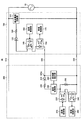
図1は、実施の形態1に係る空気調和機の通信回路の構成例を示す回路図である。実施の形態1に係る空気調和機の通信回路10は、図1に示すように、第1の装置である室外機100と、第2の装置である室内機200とが、電源線510と、信号線520と、共用線530との3線で接続されるシステムである。
Embodiment 1.
FIG. 1 is a circuit diagram showing a configuration example of a communication circuit of the air conditioner according to the first embodiment. In the communication circuit 10 of the air conditioner according to the first embodiment, as shown in FIG. 1, the outdoor unit 100 which is the first device and the indoor unit 200 which is the second device have a power line 510 and a power line 510. This is a system in which the signal line 520 and the common line 530 are connected by three lines.

室外機100は、直流電源回路部110、制限抵抗120、ダイオード130、送信部140、受信部150、送信制御部160、及び受信制御部170を備える。 The outdoor unit 100 includes a DC power supply circuit unit 110, a limiting resistor 120, a diode 130, a transmission unit 140, a reception unit 150, a transmission control unit 160, and a reception control unit 170.

電源線510は、室内機200の図示しない各種の回路部に接続される。電源線510には、商用電源20が出力する電源電圧が印加される。商用電源20は、交流電力を供給する交流電源である。交流電源の一例は、200Vの電圧を出力する商用電源である。 The power line 510 is connected to various circuit units (not shown) of the indoor unit 200. A power supply voltage output by the commercial power supply 20 is applied to the power supply line 510. The commercial power source 20 is an AC power source that supplies AC power. An example of an AC power supply is a commercial power supply that outputs a voltage of 200V.

信号線520には、直流電源回路部110から供給される通信電流が流れる。通信電流は、室外機100と室内機200との間の通信に用いる電流である。室外機100及び室内機200は、電流が流れている状態と流れてない状態とを検出することで、通信を行う。 A communication current supplied from the DC power supply circuit unit 110 flows through the signal line 520. The communication current is a current used for communication between the outdoor unit 100 and the indoor unit 200. The outdoor unit 100 and the indoor unit 200 communicate by detecting a state in which a current is flowing and a state in which a current is not flowing.

共用線530には、商用電源20及び直流電源回路部110の基準電位が印加される。 The reference potential of the commercial power supply 20 and the DC power supply circuit unit 110 is applied to the common line 530.

直流電源回路部110は、前述の通信電流を供給するための直流電源である。室外機100と室内機200との間の通信を「内外通信」と呼ぶ場合がある。直流電源回路部110は、商用電源20から印加される電圧を降圧して直流電圧を生成する。 The DC power supply circuit unit 110 is a DC power supply for supplying the above-mentioned communication current. Communication between the outdoor unit 100 and the indoor unit 200 may be referred to as "internal / external communication". The DC power supply circuit unit 110 steps down the voltage applied from the commercial power supply 20 to generate a DC voltage.

制限抵抗120とダイオード130とは、直列に接続されて、直流電源回路部110と送信部140との間に配されている。 The limiting resistor 120 and the diode 130 are connected in series and arranged between the DC power supply circuit unit 110 and the transmitting unit 140.

制限抵抗120は、室外機100に流れる通信電流を制限する抵抗である。制限抵抗120の一端は、直流電源回路部110に接続されている。制限抵抗120の他端は、ダイオード130のアノードに接続されている。 The limiting resistor 120 is a resistor that limits the communication current flowing through the outdoor unit 100. One end of the limiting resistor 120 is connected to the DC power supply circuit unit 110. The other end of the limiting resistor 120 is connected to the anode of the diode 130.

ダイオード130は、整流素子である。ダイオード130は、電源線510の電位が共用線530の電位より高いときに電流を流す機能を有する。 The diode 130 is a rectifying element. The diode 130 has a function of passing a current when the potential of the power supply line 510 is higher than the potential of the common line 530.

図1では、制限抵抗120の他端がダイオード130のアノードに接続される構成を例示しているが、制限抵抗120とダイオード130との接続を逆にしてもよい。すなわち、ダイオード130のアノードが直流電源回路部110に接続され、ダイオード130のカソードが制限抵抗120の一端に接続されていてもよい。 Although FIG. 1 illustrates a configuration in which the other end of the limiting resistor 120 is connected to the anode of the diode 130, the connection between the limiting resistor 120 and the diode 130 may be reversed. That is, the anode of the diode 130 may be connected to the DC power supply circuit unit 110, and the cathode of the diode 130 may be connected to one end of the limiting resistor 120.

送信部140は、内外通信の際に通信電流が流れる経路の状態を、通信電流が流れる状態と、流れない状態との何れかに切り替えるスイッチング素子である。スイッチング素子の一例は、フォトカプラである。以下、内外通信の際に通信電流が流れる経路を「カレントループ」と呼ぶ。通信電流が流れる経路は、室外機100内の直流電源回路部110、制限抵抗120、ダイオード130、送信部140及び受信部150と、室内機200内の後述するダイオード210、制限抵抗220、通信制御部250、送信部230及び受信部240とが信号線520を介して直列に接続されて形成される経路である。なお、以下では、カレントループに通信電流が流れる状態を「ON状態」又は単に「ON」と呼び、通信電流が流れない状態を「OFF状態」又は単に「OFF」と呼ぶ場合がある。 The transmission unit 140 is a switching element that switches the state of the path through which the communication current flows during internal / external communication between a state in which the communication current flows and a state in which the communication current does not flow. An example of a switching element is a photocoupler. Hereinafter, the path through which the communication current flows during internal / external communication is referred to as a "current loop". The paths through which the communication current flows are the DC power supply circuit unit 110, the limiting resistor 120, the diode 130, the transmitting unit 140 and the receiving unit 150 in the outdoor unit 100, and the diode 210, the limiting resistor 220, and the communication control described later in the indoor unit 200. This is a path formed by connecting the unit 250, the transmitting unit 230, and the receiving unit 240 in series via a signal line 520. In the following, the state in which the communication current flows in the current loop may be referred to as "ON state" or simply "ON", and the state in which the communication current does not flow may be referred to as "OFF state" or simply "OFF".

送信部140は、送信制御部160の制御に従って、カレントループのON又はOFFの制御を行う。送信部140は、カレントループのON又はOFFの制御によって室内機200にデータを送信する。 The transmission unit 140 controls ON or OFF of the current loop according to the control of the transmission control unit 160. The transmission unit 140 transmits data to the indoor unit 200 by controlling ON or OFF of the current loop.

受信部150は、室内機200から送信されるデータを受信する素子である。受信部150は、カレントループに流れる通信電流値が通信電流閾値よりも大きいか又は小さいかを検出することでデータを受信する。当該素子の一例は、フォトカプラである。受信部150は、受信結果を受信制御部170に出力する。 The receiving unit 150 is an element that receives data transmitted from the indoor unit 200. The receiving unit 150 receives data by detecting whether the communication current value flowing in the current loop is larger or smaller than the communication current threshold value. An example of the device is a photocoupler. The reception unit 150 outputs the reception result to the reception control unit 170.

送信制御部160は、送信データの「0」又は「1」に応じて、送信部140のON又はOFFの制御を行う。送信データが「0」のときに、送信部140がONに制御されてもよいし、OFFに制御されてもよい。送信データが「1」のときに、送信部140がONに制御されてもよいし、OFFに制御されてもよい。 The transmission control unit 160 controls ON or OFF of the transmission unit 140 according to "0" or "1" of the transmission data. When the transmission data is "0", the transmission unit 140 may be controlled to be ON or OFF. When the transmission data is "1", the transmission unit 140 may be controlled to be ON or OFF.

受信制御部170は、受信部150の出力から受信データの「0」又は「1」を判断する。 The reception control unit 170 determines "0" or "1" of the received data from the output of the reception unit 150.

室内機200は、ダイオード210、制限抵抗220、送信部230、受信部240、通信制御部250、誤接続検出部260、送信制御部270、受信制御部280、及び抵抗290を備える。 The indoor unit 200 includes a diode 210, a limiting resistor 220, a transmitting unit 230, a receiving unit 240, a communication control unit 250, a false connection detection unit 260, a transmission control unit 270, a reception control unit 280, and a resistor 290.

ダイオード210と、制限抵抗220とは、直列に接続されている。ダイオード210及び制限抵抗220は、室内機200において、室外機100の受信部150と誤接続検出部260との接続点520aと、通信制御部250との間に配されている。 The diode 210 and the limiting resistor 220 are connected in series. The diode 210 and the limiting resistor 220 are arranged between the connection point 520a between the receiving unit 150 of the outdoor unit 100 and the erroneous connection detection unit 260 and the communication control unit 250 in the indoor unit 200.

ダイオード210は、整流素子である。ダイオード210は、一定の方向にのみ通信電流を流す。ダイオード210のアノードは、接続点520aに接続されている。 The diode 210 is a rectifying element. The diode 210 causes a communication current to flow only in a certain direction. The anode of the diode 210 is connected to the connection point 520a.

制限抵抗220は、室内機200に流れる通信電流を制御する抵抗である。図1では、制限抵抗220の一端がダイオード210のカソードに接続され、制限抵抗220の他端が通信制御部250に接続される構成を例示しているが、ダイオード210と制限抵抗220との接続を逆にしてもよい。すなわち、制限抵抗220の一端が室外機100の受信部150と誤接続検出部260との接続点520aに接続され、制限抵抗220の他端がダイオード210のアノードに接続されていてもよい。 The limiting resistor 220 is a resistor that controls the communication current flowing through the indoor unit 200. FIG. 1 illustrates a configuration in which one end of the limiting resistor 220 is connected to the cathode of the diode 210 and the other end of the limiting resistor 220 is connected to the communication control unit 250. However, the connection between the diode 210 and the limiting resistor 220 is illustrated. May be reversed. That is, one end of the limiting resistor 220 may be connected to the connection point 520a between the receiving unit 150 of the outdoor unit 100 and the erroneous connection detecting unit 260, and the other end of the limiting resistor 220 may be connected to the anode of the diode 210.

送信部230は、カレントループの状態を、通信電流が流れる状態と、流れない状態との何れかに切り替えるスイッチング素子である。送信部230は、送信制御部270の制御に従って、カレントループのON又はOFFの制御を行う。送信部230は、カレントループのON又はOFFの制御によって室外機100にデータを送信する。 The transmission unit 230 is a switching element that switches the state of the current loop between a state in which a communication current flows and a state in which a communication current does not flow. The transmission unit 230 controls ON or OFF of the current loop according to the control of the transmission control unit 270. The transmission unit 230 transmits data to the outdoor unit 100 by controlling ON or OFF of the current loop.

受信部240は、室外機100から送信されるデータを受信する素子である。受信部240は、カレントループに流れる通信電流値が通信電流閾値よりも大きいか又は小さいかを検出することでデータを受信する。当該素子の一例は、フォトカプラである。受信部240は、出力結果を受信制御部280に出力する。 The receiving unit 240 is an element that receives data transmitted from the outdoor unit 100. The receiving unit 240 receives data by detecting whether the communication current value flowing in the current loop is larger or smaller than the communication current threshold value. An example of the device is a photocoupler. The receiving unit 240 outputs the output result to the receiving control unit 280.

送信制御部270は、送信データの「0」又は「1」に応じて、送信部230のON又はOFFの制御を行う。送信データが「0」のときに、送信部230がONに制御されてもよいし、OFFに制御されてもよい。送信データが「1」のときに、送信部230がONに制御されてもよいし、OFFに制御されてもよい。 The transmission control unit 270 controls ON or OFF of the transmission unit 230 according to "0" or "1" of the transmission data. When the transmission data is "0", the transmission unit 230 may be controlled to be ON or OFF. When the transmission data is "1", the transmission unit 230 may be controlled to be ON or OFF.

受信制御部280は、受信部240の出力から受信データの「0」又は「1」を判断する。 The reception control unit 280 determines "0" or "1" of the received data from the output of the reception unit 240.

通信制御部250は、誤接続検出部260からの検出結果に応じて、カレントループのON状態又はOFF状態を制御する。但し、通信制御部250は、誤接続検出部260から検出結果を受け取るまでは、カレントループをOFF状態とする。 The communication control unit 250 controls the ON state or the OFF state of the current loop according to the detection result from the erroneous connection detection unit 260. However, the communication control unit 250 turns off the current loop until the detection result is received from the erroneous connection detection unit 260.

誤接続検出部260は、電源線510と信号線520との間の誤接続を検出する回路である。誤接続検出部260は、共用線530と信号線520との間の電位差の情報を基に、電源線510と信号線520との間の誤接続を検出する。具体的に、誤接続検出部260は、共用線530の電位が信号線520の電位よりも判定値以上高くなったとき、すなわち共用線530と信号線520との間の電位差が判定値以上高くなったとき、信号線520と電源線510との間の誤接続を検出する。以下、信号線520と電源線510とが正しく接続されているときを「正常接続時」と呼び、信号線520と電源線510とが誤接続されているときを「誤接続時」と呼び、信号線520と電源線510との間の誤接続を検出したときを「誤接続検出時」と呼ぶ。 The erroneous connection detection unit 260 is a circuit that detects an erroneous connection between the power supply line 510 and the signal line 520. The erroneous connection detection unit 260 detects the erroneous connection between the power supply line 510 and the signal line 520 based on the information of the potential difference between the common line 530 and the signal line 520 . Specifically, when the potential of the common line 530 is higher than the potential of the signal line 520, that is, the potential difference between the common line 530 and the signal line 520 is higher than the judgment value. When this happens, an erroneous connection between the signal line 520 and the power supply line 510 is detected. Hereinafter, the time when the signal line 520 and the power supply line 510 are correctly connected is referred to as "normal connection", and the time when the signal line 520 and the power supply line 510 are erroneously connected is referred to as "misconnection". The time when an erroneous connection between the signal line 520 and the power supply line 510 is detected is referred to as "when an erroneous connection is detected".

抵抗290は、誤接続時に送信部230及び受信部240の両端に印加される電圧を制限する抵抗である。正常接続時に抵抗290に流れる通信電流を小さくするため、抵抗290は、大きな抵抗値のものが選定される。抵抗290の抵抗値の典型例は、数MΩである。 The resistor 290 is a resistor that limits the voltage applied to both ends of the transmitting unit 230 and the receiving unit 240 at the time of incorrect connection. A resistor 290 having a large resistance value is selected in order to reduce the communication current flowing through the resistor 290 at the time of normal connection. A typical example of the resistance value of the resistor 290 is several MΩ.

通信制御部250がOFF状態のときのインピーダンスを「第1インピーダンス値」と呼ぶ。誤接続検出時において、送信部230がOFF状態の場合、商用電源20の出力電圧は、ダイオード210のON抵抗値と、抵抗220の抵抗値と、第1インピーダンス値と、抵抗290の抵抗値とで分圧される。このとき、抵抗290による分圧電圧が、送信部230及び受信部240の両端に印加される。 The impedance when the communication control unit 250 is in the OFF state is called a "first impedance value". When the transmission unit 230 is in the OFF state at the time of erroneous connection detection, the output voltage of the commercial power supply 20 is the ON resistance value of the diode 210, the resistance value of the resistor 220, the first impedance value, and the resistance value of the resistor 290. The voltage is divided by. At this time, the voltage dividing voltage due to the resistor 290 is applied to both ends of the transmitting unit 230 and the receiving unit 240.

次に、実施の形態1の空気調和機の通信回路における通信動作について説明する。 Next, the communication operation in the communication circuit of the air conditioner of the first embodiment will be described.

<室外機100から室内機200へデータを送信する場合の動作>
ステップ1:室内機200の送信制御部270は、室内機200の送信部230をON状態にする。
ステップ2:室外機100の送信制御部160は、送信データの「0」又は「1」に基づいて、室外機100の送信部140のON制御又はOFF制御を行う。
ステップ3:室内機200の受信部240は、受信結果を室内機200の受信制御部280に出力する。
ステップ4:室内機200の受信制御部280は、入力結果から受信データの「0」、「1」を判断する。
<Operation when data is transmitted from the outdoor unit 100 to the indoor unit 200>
Step 1: The transmission control unit 270 of the indoor unit 200 turns on the transmission unit 230 of the indoor unit 200.
Step 2: The transmission control unit 160 of the outdoor unit 100 performs ON control or OFF control of the transmission unit 140 of the outdoor unit 100 based on "0" or "1" of the transmission data.
Step 3: The reception unit 240 of the indoor unit 200 outputs the reception result to the reception control unit 280 of the indoor unit 200.
Step 4: The reception control unit 280 of the indoor unit 200 determines "0" and "1" of the received data from the input result.

<室内機200から室外機100へデータを送信する場合の動作>
ステップ1:室外機100の送信制御部160は、室外機100の送信部140をON状態にする。
ステップ2:室内機200の送信制御部270は、送信データの「0」又は「1」に基づいて、室内機200の送信部230のON制御又はOFF制御を行う。
ステップ3:室外機100の受信部150は、受信結果を室外機100の受信制御部170に出力する。
ステップ4:室外機100の受信制御部170は、入力結果から受信データの「0」又は「1」を判断する。
<Operation when data is transmitted from the indoor unit 200 to the outdoor unit 100>
Step 1: The transmission control unit 160 of the outdoor unit 100 turns on the transmission unit 140 of the outdoor unit 100.
Step 2: The transmission control unit 270 of the indoor unit 200 performs ON control or OFF control of the transmission unit 230 of the indoor unit 200 based on "0" or "1" of the transmission data.
Step 3: The receiving unit 150 of the outdoor unit 100 outputs the reception result to the reception control unit 170 of the outdoor unit 100.
Step 4: The reception control unit 170 of the outdoor unit 100 determines "0" or "1" of the received data from the input result.

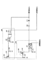
次に、実施の形態1における通信制御部250及び誤接続検出部260の構成について説明する。図2は、実施の形態1における通信制御部250及び誤接続検出部260の構成例を示す詳細回路図である。 Next, the configuration of the communication control unit 250 and the erroneous connection detection unit 260 in the first embodiment will be described. FIG. 2 is a detailed circuit diagram showing a configuration example of the communication control unit 250 and the erroneous connection detection unit 260 according to the first embodiment.

通信制御部250は、フォトカプラ251、トランジスタ252、抵抗253、抵抗254、及び電源端子255を備える。 The communication control unit 250 includes a photocoupler 251, a transistor 252, a resistor 253, a resistor 254, and a power supply terminal 255.

フォトカプラ251は、誤接続検出部260の検出結果に基づき、カレントループのON状態又はOFF状態を制御する回路素子である。フォトカプラ251は、高耐圧のフォトカプラである。 The photocoupler 251 is a circuit element that controls the ON state or the OFF state of the current loop based on the detection result of the erroneous connection detection unit 260. The photocoupler 251 is a high withstand voltage photocoupler.

トランジスタ252は、抵抗254に生じた電圧に応じて、フォトカプラ251の発光側に流れる電流を制御する。 The transistor 252 controls the current flowing on the light emitting side of the photocoupler 251 according to the voltage generated in the resistor 254.

抵抗253は、フォトカプラ251の発光側に流れる電流を制限する抵抗である。 The resistor 253 is a resistor that limits the current flowing on the light emitting side of the photocoupler 251.

抵抗254は、後述するトランジスタ265に流れるコレクタ電流を制限する抵抗である。 The resistor 254 is a resistor that limits the collector current flowing through the transistor 265, which will be described later.

電源端子255は、フォトカプラ251及びトランジスタ252に動作電圧を印加するための電源端子である。電源端子255には、直流電源回路部110とは異なる図示しない電源回路によって生成された直流電圧が印加される。直流電圧の一例は、5Vである。 The power supply terminal 255 is a power supply terminal for applying an operating voltage to the photocoupler 251 and the transistor 252. A DC voltage generated by a power supply circuit (not shown) different from the DC power supply circuit unit 110 is applied to the power supply terminal 255. An example of a DC voltage is 5V.

誤接続検出部260は、フォトカプラ261、抵抗262、抵抗263、コンデンサ264、トランジスタ265、及び電源端子266を備える。 The erroneous connection detection unit 260 includes a photocoupler 261, a resistor 262, a resistor 263, a capacitor 264, a transistor 265, and a power supply terminal 266.

フォトカプラ261は、共用線530の電位が信号線520の電位よりも判定値以上高くなったことを検出する。フォトカプラ261は、正常接続時における信号線520と共用線530との間の電位差と、誤接続時における信号線520と共用線530との間の電位差との差異を検出する。 The photocoupler 261 detects that the potential of the common line 530 is higher than the potential of the signal line 520 by a determination value or more. The photocoupler 261 detects the difference between the potential difference between the signal line 520 and the common line 530 at the time of normal connection and the potential difference between the signal line 520 and the common line 530 at the time of incorrect connection.

抵抗262は、フォトカプラ261の発光側に流れる電流を制限する抵抗である。 The resistor 262 is a resistor that limits the current flowing on the light emitting side of the photocoupler 261.

抵抗263は、フォトカプラ261の発光側に流れる電流の閾値を決める抵抗である。 The resistor 263 is a resistor that determines the threshold value of the current flowing on the light emitting side of the photocoupler 261.

コンデンサ264は、容量素子である。コンデンサ264の容量値は、コンデンサ264を充電するときの充電時間と、電源周期とを考慮して設定される。コンデンサ264の充電時間は、電源周期に比べて長く設定される。コンデンサ264の容量値が大きい程、充電時間は長くなる。 The capacitor 264 is a capacitive element. The capacitance value of the capacitor 264 is set in consideration of the charging time when charging the capacitor 264 and the power supply cycle. The charging time of the capacitor 264 is set longer than the power supply cycle. The larger the capacitance value of the capacitor 264, the longer the charging time.

トランジスタ265は、コンデンサ264に生じた電圧に応じて、抵抗254に流れる電流を制御する。 The transistor 265 controls the current flowing through the resistor 254 according to the voltage generated in the capacitor 264.

電源端子266は、トランジスタ265及びフォトカプラ261に動作電圧を印加し、コンデンサ264への充電電力を供給するための電源端子である。電源端子266には、直流電源回路部110とは異なる図示しない電源回路によって生成された直流電圧が印加される。直流電圧の一例は、5Vである。 The power supply terminal 266 is a power supply terminal for applying an operating voltage to the transistor 265 and the photocoupler 261 to supply charging power to the capacitor 264. A DC voltage generated by a power supply circuit (not shown) different from the DC power supply circuit unit 110 is applied to the power supply terminal 266. An example of a DC voltage is 5V.

次に、実施の形態1における通信制御部250及び誤接続検出部260の動作について説明する。 Next, the operations of the communication control unit 250 and the erroneous connection detection unit 260 in the first embodiment will be described.

<正常接続時の動作>
(1)電源投入時、コンデンサ264の電荷は放電されており、コンデンサ264の電圧は接地電位である。これにより、トランジスタ265は順バイアスされ、ON状態である。
<Operation at normal connection>
(1) When the power is turned on, the electric charge of the capacitor 264 is discharged, and the voltage of the capacitor 264 is the ground potential. As a result, the transistor 265 is forward-biased and is in the ON state.

(2)トランジスタ265はON状態であるため、電源が投入されると、抵抗254に電流が流れる。その結果、抵抗254の両端に電圧が発生する。これにより、トランジスタ252は逆バイアスされ、トランジスタ252はOFF状態である。 (2) Since the transistor 265 is in the ON state, a current flows through the resistor 254 when the power is turned on. As a result, a voltage is generated across the resistor 254. As a result, the transistor 252 is reverse-biased, and the transistor 252 is in the OFF state.

(3)トランジスタ252はOFF状態であり、フォトカプラ251の発光側には電流は流れない。これにより、フォトカプラ251は、OFF状態である。 (3) The transistor 252 is in the OFF state, and no current flows on the light emitting side of the photocoupler 251. As a result, the photocoupler 251 is in the OFF state.

(4)トランジスタ265のON状態が継続すると、コンデンサ264にトランジスタ265のベース−エミッタ間抵抗を経由して充電電流が流れる。これにより、コンデンサ264の電圧が上昇する。 (4) When the ON state of the transistor 265 continues, a charging current flows through the capacitor 264 via the base-emitter resistance of the transistor 265. As a result, the voltage of the capacitor 264 rises.

(5)コンデンサ264の電圧が上昇すると、トランジスタ265はON状態からOFF状態になる。 (5) When the voltage of the capacitor 264 rises, the transistor 265 goes from the ON state to the OFF state.

(6)トランジスタ265がON状態からOFF状態になると、抵抗254に電流が流れなくなる。これにより、トランジスタ252はON状態になる。 (6) When the transistor 265 changes from the ON state to the OFF state, no current flows through the resistor 254. As a result, the transistor 252 is turned on.

(7)トランジスタ252がON状態になると、フォトカプラ251の発光側に電流が流れる。これにより、フォトカプラ251の受光側はON状態となる。その結果、室外機100と室内機200とは、内外通信可能な状態になる。 (7) When the transistor 252 is turned on, a current flows on the light emitting side of the photocoupler 251. As a result, the light receiving side of the photocoupler 251 is turned on. As a result, the outdoor unit 100 and the indoor unit 200 are in a state where they can communicate inside and outside.

(8)以降、室外機100と室内機200との間で内外通信が開始される。 After (8), internal / external communication is started between the outdoor unit 100 and the indoor unit 200.

<誤接続時の動作>
(1)電源投入時、コンデンサ264は充電されておらず、コンデンサ264の電圧は接地電位である。これにより、トランジスタ265は順バイアスされ、ON状態である。
<Operation at the time of incorrect connection>
(1) When the power is turned on, the capacitor 264 is not charged, and the voltage of the capacitor 264 is the ground potential. As a result, the transistor 265 is forward-biased and is in the ON state.

(2)トランジスタ265はON状態であるため、電源が投入されると、抵抗254に電流が流れる。その結果、抵抗254の両端に電圧が発生する。これにより、トランジスタ252は逆バイアスされ、トランジスタ252はOFF状態である。 (2) Since the transistor 265 is in the ON state, a current flows through the resistor 254 when the power is turned on. As a result, a voltage is generated across the resistor 254. As a result, the transistor 252 is reverse-biased, and the transistor 252 is in the OFF state.

(3)トランジスタ252はOFF状態であり、フォトカプラ251の発光側には電流は流れない。これにより、フォトカプラ251は、OFF状態である。 (3) The transistor 252 is in the OFF state, and no current flows on the light emitting side of the photocoupler 251. As a result, the photocoupler 251 is in the OFF state.

(4)トランジスタ265のON状態が継続すると、コンデンサ264にトランジスタ265のベース−エミッタ間抵抗を経由して充電電流が流れる。これにより、コンデンサ264の電圧が上昇する。 (4) When the ON state of the transistor 265 continues, a charging current flows through the capacitor 264 via the base-emitter resistance of the transistor 265. As a result, the voltage of the capacitor 264 rises.

(5)電源線510には、商用電源20が出力する電源電圧が印加される。このため、信号線520と電源線510とが誤接続されていると、室内機200の信号線520には、電源線510が出力する電源電圧が信号線520に印加され、電源電圧の半周期では負極性の電圧が印加される。従って、誤接続時においては、共用線530の電位が信号線520の電位よりも一定値以上高くなる状態が生起する。 (5) A power supply voltage output by the commercial power supply 20 is applied to the power supply line 510. Therefore, if the signal line 520 and the power supply line 510 are erroneously connected, the power supply voltage output by the power supply line 510 is applied to the signal line 520 of the indoor unit 200, and the power supply voltage is half-cycled. Then, a negative voltage is applied. Therefore, at the time of incorrect connection, a state occurs in which the potential of the common line 530 is higher than the potential of the signal line 520 by a certain value or more.

(6)共用線530の電位が信号線520の電位よりも一定値以上高くなると、フォトカプラ261の発光側に電流が流れる。これにより、フォトカプラ261の受光側はON状態となる。 (6) When the potential of the common line 530 is higher than the potential of the signal line 520 by a certain value or more, a current flows on the light emitting side of the photocoupler 261. As a result, the light receiving side of the photocoupler 261 is turned on.

(7)フォトカプラ251の受光側がON状態になると、フォトカプラ261の受光側に電流が流れ、コンデンサ264の電荷は放電される。これにより、コンデンサ264の電圧は低下する。フォトカプラ261の受光側がON状態であるとき、フォトカプラ261における受光側のエミッタ−コレクタ間電圧は、0.3V程度である。このため、放電時におけるコンデンサ264の電圧も、同程度の電圧となる。 (7) When the light receiving side of the photocoupler 251 is turned on, a current flows through the light receiving side of the photocoupler 261 and the electric charge of the capacitor 264 is discharged. As a result, the voltage of the capacitor 264 drops. When the light receiving side of the photocoupler 261 is in the ON state, the emitter-collector voltage on the light receiving side of the photocoupler 261 is about 0.3 V. Therefore, the voltage of the capacitor 264 at the time of discharging is also the same voltage.

(8)上記の(4)から(7)の動作が繰り返されるが、コンデンサ264の充電時間は、電源周期に比べて長く設定されているため、コンデンサ264の電圧は、トランジスタ265をOFF状態にさせる値まで上昇しない。これにより、トランジスタ265はON状態を継続する。 (8) The above operations (4) to (7) are repeated, but since the charging time of the capacitor 264 is set longer than the power supply cycle, the voltage of the capacitor 264 turns the transistor 265 into an OFF state. It does not rise to the value that makes it. As a result, the transistor 265 continues to be in the ON state.

(9)フォトカプラ251の発光側には、電流は流れない。このため、フォトカプラ251は、OFF状態を継続する。 (9) No current flows on the light emitting side of the photocoupler 251. Therefore, the photocoupler 251 continues in the OFF state.

上記の通り、誤接続時においては、フォトカプラ251のOFF状態が継続される。その結果、送信部230がON状態であるかOFF状態であるかに関わらず、送信部230及び受信部240には電流は流れない。これにより、誤接続時における過電流保護が可能となる。 As described above, in the case of incorrect connection, the OFF state of the photocoupler 251 is continued. As a result, no current flows through the transmitting unit 230 and the receiving unit 240 regardless of whether the transmitting unit 230 is in the ON state or the OFF state. This enables overcurrent protection in the event of incorrect connection.

また、誤接続時において、電源電圧は、高耐圧素子であるフォトカプラ251に印加される。このため、送信部230及び受信部240には大電圧が印加されない。これにより、誤接続時における過電圧保護が可能となる。 Further, at the time of incorrect connection, the power supply voltage is applied to the photocoupler 251 which is a high withstand voltage element. Therefore, a large voltage is not applied to the transmitting unit 230 and the receiving unit 240. This enables overvoltage protection in the event of incorrect connection.

次に、実施の形態1の通信制御部250及び誤接続検出部260における制御シーケンスについて説明する。 Next, the control sequence in the communication control unit 250 and the erroneous connection detection unit 260 of the first embodiment will be described.

図3は、実施の形態1の通信制御部250及び誤接続検出部260における正常接続時の制御シーケンスを示すシーケンスチャートである。前述の通り、電源が投入される前においては、カレントループはOFFの状態である(ステップS11)。電源が投入されると(ステップS12)、誤接続検出部260は、誤接続の判定を行う(ステップS13)。誤接続検出部260が検出結果を出力するまで、通信制御部250は、カレントループOFFの状態を継続する(ステップS14)。すなわち、通信制御部250は、誤接続検出部260が正常接続の検出結果を出力するまでカレントループOFFの状態を継続して、送信部230及び受信部240に通信電流を流さない。誤接続検出部260の検出結果が正常接続であった場合、通信制御部250は、カレントループをON状態とする(ステップS15)。これにより、送信部230及び受信部240に通信電流が流れるようになる。以降、室外機100と室内機200との間で内外通信が開始される。 FIG. 3 is a sequence chart showing a control sequence at the time of normal connection in the communication control unit 250 and the erroneous connection detection unit 260 of the first embodiment. As described above, the current loop is in the OFF state before the power is turned on (step S11). When the power is turned on (step S12), the erroneous connection detection unit 260 determines the erroneous connection (step S13). The communication control unit 250 continues the current loop OFF state until the erroneous connection detection unit 260 outputs the detection result (step S14). That is, the communication control unit 250 continues the current loop OFF state until the erroneous connection detection unit 260 outputs the detection result of the normal connection, and does not pass the communication current to the transmission unit 230 and the reception unit 240. When the detection result of the erroneous connection detection unit 260 is a normal connection, the communication control unit 250 turns on the current loop (step S15). As a result, a communication current flows through the transmitting unit 230 and the receiving unit 240. After that, internal / external communication is started between the outdoor unit 100 and the indoor unit 200.

図4は、実施の形態1の通信制御部250及び誤接続検出部260における誤接続時の制御シーケンスを示すシーケンスチャートである。図4において、図3と同一の処理については、同一の符号を付している。 FIG. 4 is a sequence chart showing a control sequence at the time of erroneous connection in the communication control unit 250 and the erroneous connection detection unit 260 of the first embodiment. In FIG. 4, the same processing as in FIG. 3 is designated by the same reference numerals.

図3のシーケンスと同様に、誤接続検出部260が検出結果を出力するまで、カレントループOFFの状態が継続される(ステップS11からステップS14)。誤接続検出部260の検出結果が誤接続であった場合、通信制御部250は、カレントループOFFの状態を継続する(ステップS16)。従って、室外機100と室内機200との間の内外通信は開始されない。 Similar to the sequence of FIG. 3, the current loop OFF state is continued until the erroneous connection detection unit 260 outputs the detection result (steps S11 to S14). If the detection result of the erroneous connection detection unit 260 is an erroneous connection, the communication control unit 250 continues the current loop OFF state (step S16). Therefore, the internal / external communication between the outdoor unit 100 and the indoor unit 200 is not started.

上記の通り、誤接続検出部260の検出結果が誤接続であった場合、送信部230の状態がON状態であるかOFF状態であるかに関わらず、送信部230には通信電流は流れない。また、電源電圧は、主に通信制御部250に印加されるため、送信部230及び受信部240には、高電圧が印加されない。 As described above, when the detection result of the erroneous connection detection unit 260 is an erroneous connection, no communication current flows through the transmission unit 230 regardless of whether the transmission unit 230 is in the ON state or the OFF state. .. Further, since the power supply voltage is mainly applied to the communication control unit 250, a high voltage is not applied to the transmission unit 230 and the reception unit 240.

以上の説明の通り、実施の形態1に係る空気調和機の通信回路10によれば、信号線520と電源線510とを誤接続した場合でも、送信部230及び受信部240に過電流が流れることと、送信部230及び受信部240に過電圧が印加されるのを抑止することができる。 As described above, according to the communication circuit 10 of the air conditioner according to the first embodiment, an overcurrent flows through the transmitting unit 230 and the receiving unit 240 even when the signal line 520 and the power supply line 510 are erroneously connected. In addition, it is possible to prevent an overvoltage from being applied to the transmitting unit 230 and the receiving unit 240.

また、実施の形態1に係る空気調和機の通信回路10によれば、送信部230及び受信部240に過電圧が印加されるのを抑止することができるので、高耐圧のフォトカプラを使用せずに、通信回路を構成することができる。これにより、送信部230及び受信部240には、処理速度の高い通常耐圧のフォトカプラを選定することができ、通信速度の高速化を容易に実現することができる。 Further, according to the communication circuit 10 of the air conditioner according to the first embodiment, it is possible to suppress the application of overvoltage to the transmitting unit 230 and the receiving unit 240, so that a high withstand voltage photocoupler is not used. A communication circuit can be configured. As a result, a photocoupler having a high processing speed and a normal withstand voltage can be selected for the transmitting unit 230 and the receiving unit 240, and the communication speed can be easily increased.

また、実施の形態1に係る空気調和機の通信回路10によれば、誤接続時においては、カレントループOFFの状態が継続されるので、通信電流が常時遮断される。これにより、室内機200の回路素子が発熱することはない。これにより、通信回路を冷却するための放熱部品が不要であり、通信回路が大型化するのを回避することができる。 Further, according to the communication circuit 10 of the air conditioner according to the first embodiment, when the connection is erroneous, the current loop OFF state is continued, so that the communication current is always cut off. As a result, the circuit element of the indoor unit 200 does not generate heat. As a result, a heat radiating component for cooling the communication circuit is unnecessary, and it is possible to prevent the communication circuit from becoming large in size.

また、実施の形態1に係る空気調和機の通信回路10によれば、通信制御部250及び誤接続検出部260はアナログ回路で構成するので、マイコンといったプロセッサを使用する制御は不要となる。そのため、プロセッサの制御ポートを追加するといったプロセッサ周辺の改修は実施せずに、通信制御部250及び誤接続検出部260を実現できる。 Further, according to the communication circuit 10 of the air conditioner according to the first embodiment, since the communication control unit 250 and the erroneous connection detection unit 260 are composed of an analog circuit, control using a processor such as a microcomputer becomes unnecessary. Therefore, the communication control unit 250 and the erroneous connection detection unit 260 can be realized without performing modifications around the processor such as adding a control port of the processor.

更に、実施の形態1に係る空気調和機の通信回路10によれば、アナログ回路で構成された通信制御部250及び誤接続検出部260を用いるので、通信制御部250及び誤接続検出部260の制御のためのソフト開発が不要である。これにより、新規機能の開発のためのコストの削減が可能となる。 Further, according to the communication circuit 10 of the air conditioner according to the first embodiment, since the communication control unit 250 and the erroneous connection detection unit 260 configured by the analog circuit are used, the communication control unit 250 and the erroneous connection detection unit 260 There is no need to develop software for control. This makes it possible to reduce the cost for developing new functions.

更に、実施の形態1に係る空気調和機の通信回路10によれば、送信部230がON状態であるかOFF状態であるかに関わらず、誤接続に対する保護を実現できる。これにより、プロセッサが暴走し、送信制御部270の出力が意図した制御と異なるような状況が生起したとしても、通信制御部250及び誤接続検出部260が動作不良を起こすことはない。これにより、信頼性の高い誤接続保護の実現が可能となる。 Further, according to the communication circuit 10 of the air conditioner according to the first embodiment, protection against erroneous connection can be realized regardless of whether the transmission unit 230 is in the ON state or the OFF state. As a result, even if the processor goes out of control and a situation occurs in which the output of the transmission control unit 270 is different from the intended control, the communication control unit 250 and the erroneous connection detection unit 260 do not malfunction. This makes it possible to realize highly reliable protection against erroneous connections.

なお、図1では、室内機200に通信制御部250及び誤接続検出部260を搭載しているが、室外機100に搭載してもよい。 Although the communication control unit 250 and the erroneous connection detection unit 260 are mounted on the indoor unit 200 in FIG. 1, they may be mounted on the outdoor unit 100.

また、上述の説明では、共用線530の電位が信号線520の電位よりも一定値以上高くなったことを検出する構成としているが、この構成には限定されない。信号線520と共用線530との間に交流電源が接続されたことを検出する構成でもよい。或いは、信号線520と共用線530との間に過電圧が印加されたことを検出する構成でもよい。すなわち、信号線520と電源線510とが誤接続されたことを検出する回路構成であれば、どのような構成でもよい。 Further, in the above description, the configuration is such that the potential of the common line 530 is detected to be higher than the potential of the signal line 520 by a certain value or more, but the configuration is not limited to this. It may be configured to detect that an AC power supply is connected between the signal line 520 and the common line 530. Alternatively, it may be configured to detect that an overvoltage has been applied between the signal line 520 and the common line 530. That is, any configuration may be used as long as it has a circuit configuration for detecting that the signal line 520 and the power supply line 510 are erroneously connected.

また、室内機200又は室外機100に表示部を設け、誤接続の検出結果を表示する機能を付加してもよい。本機能により、作業者又は使用者に、誤接続の検出結果を通知できるので、誤接続という事象に対する迅速な対応が可能になる。 Further, the indoor unit 200 or the outdoor unit 100 may be provided with a display unit to add a function of displaying the detection result of erroneous connection. With this function, the operator or the user can be notified of the detection result of the erroneous connection, so that it is possible to quickly respond to the event of the erroneous connection.

また、図1では、1台の室外機100に1台の室内機200を接続する構成としているが、室外機1台と複数の室内機から構成されるマルチタイプの空気調和機に適用することも可能である。 Further, in FIG. 1, one indoor unit 200 is connected to one outdoor unit 100, but this can be applied to a multi-type air conditioner composed of one outdoor unit and a plurality of indoor units. Is also possible.

実施の形態2.
図5は、実施の形態2に係る空気調和機の通信回路の構成例を示す回路図である。図5に示す実施の形態2に係る空気調和機の通信回路10Aは、図1に示す実施の形態1に係る空気調和機の通信回路10において、室内機200が室内機200Aに変更されている。室内機200Aは、室内機200の構成に瞬停検出部300が付加されている。「瞬停」とは、「瞬時停電」の略称である。
Embodiment 2.
FIG. 5 is a circuit diagram showing a configuration example of a communication circuit of the air conditioner according to the second embodiment. In the communication circuit 10A of the air conditioner according to the second embodiment shown in FIG. 5, the indoor unit 200 is changed to the indoor unit 200A in the communication circuit 10 of the air conditioner according to the first embodiment shown in FIG. .. In the indoor unit 200A, a momentary power failure detection unit 300 is added to the configuration of the indoor unit 200. "Instantaneous power outage" is an abbreviation for "instantaneous power outage".

瞬停検出部300は、電源線510と共用線530との間に交流電力を供給する商用電源20の瞬停を検出する回路である。ここで、「瞬停」とは、商用電源20からの電力供給が、数マイクロ秒から数百ミリ秒の間絶たれてしまう電源障害現象を指して言う。 The momentary power failure detection unit 300 is a circuit that detects the momentary power failure of the commercial power source 20 that supplies AC power between the power supply line 510 and the common line 530. Here, the "instantaneous power failure" refers to a power failure phenomenon in which the power supply from the commercial power source 20 is interrupted for a period of several microseconds to several hundred milliseconds.

瞬停検出部300は、電源線510と共用線530と誤接続検出部260に接続される。瞬停検出部300は、商用電源20から電力の供給を受ける。瞬停検出部300の検出結果は、誤接続検出部260に出力される。なお、その他の構成は、図1に示す空気調和機の通信回路10の構成と同一又は同等であり、同一又は同等の構成部には同一の符号を付して、重複する説明は省略する。 The momentary power failure detection unit 300 is connected to the power supply line 510, the common line 530, and the erroneous connection detection unit 260. The momentary power failure detection unit 300 receives power from the commercial power source 20. The detection result of the momentary power failure detection unit 300 is output to the erroneous connection detection unit 260. The other configurations are the same as or equivalent to the configuration of the communication circuit 10 of the air conditioner shown in FIG. 1, and the same or equivalent components are designated by the same reference numerals, and redundant description will be omitted.

次に、実施の形態2における瞬停検出部300の構成について説明する。図6は、実施の形態2における瞬停検出部300の構成例を示す詳細回路図である。図6では、瞬停検出部300と、通信制御部250及び誤接続検出部260のそれぞれとの接続関係も示している。 Next, the configuration of the momentary power failure detection unit 300 in the second embodiment will be described. FIG. 6 is a detailed circuit diagram showing a configuration example of the momentary power failure detection unit 300 according to the second embodiment. FIG. 6 also shows the connection relationship between the momentary power failure detection unit 300, the communication control unit 250, and the erroneous connection detection unit 260.

瞬停検出部300は、ダイオード301、抵抗302、フォトカプラ303、コンデンサ304、トランジスタ305、抵抗306、トランジスタ307、抵抗308、トランジスタ309、及び電源端子310を備える。 The momentary power failure detection unit 300 includes a diode 301, a resistor 302, a photocoupler 303, a capacitor 304, a transistor 305, a resistor 306, a transistor 307, a resistor 308, a transistor 309, and a power supply terminal 310.

ダイオード301は、整流素子である。ダイオード301は、電源線510の電位が共用線530の電位より高いときに電流を流す機能を有する。 The diode 301 is a rectifying element. The diode 301 has a function of passing a current when the potential of the power supply line 510 is higher than the potential of the common line 530.

抵抗302は、フォトカプラ303の発光側に流れる電流を制限する抵抗である。 The resistor 302 is a resistor that limits the current flowing on the light emitting side of the photocoupler 303.

フォトカプラ303は、電源線510の電位が共用線530の電位よりも高くなったときに動作する回路素子である。電源線510の電位が共用線530の電位よりも高くなると、フォトカプラ303の受光側は、ON状態となる。 The photocoupler 303 is a circuit element that operates when the potential of the power supply line 510 becomes higher than the potential of the common line 530. When the potential of the power supply line 510 becomes higher than the potential of the common line 530, the light receiving side of the photocoupler 303 is turned on.

コンデンサ304は、容量素子である。コンデンサ304の容量値は、コンデンサ304を充電するときの充電時間と、電源周期とを考慮して設定される。コンデンサ304の充電時間は、電源周期に比べて長く設定される。コンデンサ304の容量値が大きい程、充電時間は長くなる。 The capacitor 304 is a capacitive element. The capacitance value of the capacitor 304 is set in consideration of the charging time when charging the capacitor 304 and the power supply cycle. The charging time of the capacitor 304 is set longer than the power supply cycle. The larger the capacitance value of the capacitor 304, the longer the charging time.

トランジスタ305は、コンデンサ304に生じた電圧に応じて、抵抗306に流れる電流を制御する。 The transistor 305 controls the current flowing through the resistor 306 according to the voltage generated in the capacitor 304.

抵抗306は、トランジスタ305に流れるコレクタ電流を制限する抵抗である。 The resistor 306 is a resistor that limits the collector current flowing through the transistor 305.

トランジスタ307は、抵抗306に生じた電圧に応じて、抵抗308に流れる電流を制御する。 The transistor 307 controls the current flowing through the resistor 308 according to the voltage generated by the resistor 306.

抵抗308は、トランジスタ307に流れるコレクタ電流を制限する抵抗である。 The resistor 308 is a resistor that limits the collector current flowing through the transistor 307.

トランジスタ309は、抵抗306に生じた電圧に応じて、ON又はOFFに制御される。トランジスタ309の動作電圧は、電源端子266から印加される。 The transistor 309 is controlled to be ON or OFF according to the voltage generated in the resistor 306. The operating voltage of the transistor 309 is applied from the power supply terminal 266.

電源端子310は、フォトカプラ303及びトランジスタ305に動作電圧を印加し、コンデンサ304への充電電力を供給するための電源端子である。電源端子310には、直流電源回路部110とは異なる図示しない電源回路によって生成された直流電圧が印加される。直流電圧の一例は、5Vである。 The power supply terminal 310 is a power supply terminal for applying an operating voltage to the photocoupler 303 and the transistor 305 to supply charging power to the capacitor 304. A DC voltage generated by a power supply circuit (not shown) different from the DC power supply circuit unit 110 is applied to the power supply terminal 310. An example of a DC voltage is 5V.

次に、実施の形態2における瞬停検出部300の動作について説明する。なお、瞬停が生起したときを「瞬停時」、瞬停が生起していないときを「非瞬停時」と呼ぶ。また、「非瞬停時」において、瞬停から復帰したときを、特に「瞬停復帰時」と呼ぶ。 Next, the operation of the momentary power failure detection unit 300 in the second embodiment will be described. The time when the momentary stop occurs is called "instantaneous stop", and the time when the momentary stop does not occur is called "non-instantaneous stop". Further, in the "non-instantaneous power failure", the time when the momentary power is restored is particularly referred to as the "instantaneous power failure recovery time".

<非瞬停時の動作>
(1)非瞬停時においては、電源線510と共用線530との間に電源電圧が正常に印加されている。
<Operation during non-instantaneous stoppage>
(1) At the time of non-instantaneous power failure, the power supply voltage is normally applied between the power supply line 510 and the common line 530.

(2)電源投入時、コンデンサ304の電荷は放電されており、コンデンサ304の電圧は接地電位である。これにより、トランジスタ305は順バイアスされ、ON状態である。 (2) When the power is turned on, the electric charge of the capacitor 304 is discharged, and the voltage of the capacitor 304 is the ground potential. As a result, the transistor 305 is forward-biased and is in the ON state.

(3)トランジスタ305はON状態であるため、抵抗306に電流が流れる。その結果、抵抗306の両端に電圧が発生する。これにより、トランジスタ307は逆バイアスされ、トランジスタ307はOFF状態である。 (3) Since the transistor 305 is in the ON state, a current flows through the resistor 306. As a result, a voltage is generated across the resistor 306. As a result, the transistor 307 is reverse-biased, and the transistor 307 is in the OFF state.

(4)トランジスタ307はOFF状態であり、抵抗308には電流は流れない。これにより、抵抗308の電位は接地電位であり、トランジスタ309はOFF状態である。 (4) The transistor 307 is in the OFF state, and no current flows through the resistor 308. As a result, the potential of the resistor 308 is the ground potential, and the transistor 309 is in the OFF state.

(5)トランジスタ305のON状態が継続すると、コンデンサ304にトランジスタ305のベース−エミッタ間抵抗を経由して充電電流が流れる。これにより、コンデンサ304の電圧が上昇する。 (5) When the ON state of the transistor 305 continues, a charging current flows through the capacitor 304 via the base-emitter resistance of the transistor 305. As a result, the voltage of the capacitor 304 rises.

(6)電源線510の電位は、共用線530の電位よりも高く、フォトカプラ303の発光側に電流が流れる。これにより、フォトカプラ303の受光側はON状態となる。 (6) The potential of the power supply line 510 is higher than the potential of the common line 530, and a current flows on the light emitting side of the photocoupler 303. As a result, the light receiving side of the photocoupler 303 is turned on.

(7)フォトカプラ303の受光側に電流が流れると、コンデンサ304の電荷は放電される。これにより、コンデンサ304の電圧は低下する。 (7) When a current flows through the light receiving side of the photocoupler 303, the electric charge of the capacitor 304 is discharged. As a result, the voltage of the capacitor 304 drops.

(8)上記(5)から(7)の動作が繰り返されるが、コンデンサ304の充電時間は、電源周期に比べて長く設定されているため、コンデンサ304の電圧は、トランジスタ305をOFF状態にさせる値まで上昇しない。これにより、トランジスタ305はON状態を継続する。 (8) The operations (5) to (7) above are repeated, but since the charging time of the capacitor 304 is set longer than the power supply cycle, the voltage of the capacitor 304 causes the transistor 305 to be turned off. Does not rise to value. As a result, the transistor 305 continues to be in the ON state.

(9)トランジスタ305はON状態を継続するので、トランジスタ307及びトランジスタ309はOFF状態を継続する。 (9) Since the transistor 305 continues in the ON state, the transistor 307 and the transistor 309 continue in the OFF state.

(10)トランジスタ309はOFF状態を継続するので、図6の回路構成において、瞬停検出部300の存在は、誤接続検出部260の動作に影響を与えない。従って、室外機100と室内機200Aとの間の内外通信にも影響を与えない。 (10) Since the transistor 309 continues to be in the OFF state, the presence of the momentary power failure detection unit 300 does not affect the operation of the erroneous connection detection unit 260 in the circuit configuration of FIG. Therefore, it does not affect the internal / external communication between the outdoor unit 100 and the indoor unit 200A.

<瞬停時の動作>
瞬停が生起する前の動作は、非瞬停時の動作と同じであり、ここでの記載は省略する。
<Operation during momentary power failure>
The operation before the momentary power failure occurs is the same as the operation during the non-momentary power failure, and the description here is omitted.

(1)瞬停が生起しても、電源端子310には、直流電圧が生じている。このため、コンデンサ304にトランジスタ305のベース−エミッタ間抵抗を経由して充電電流が流れる。これにより、コンデンサ304の電圧が上昇する。 (1) Even if a momentary power failure occurs, a DC voltage is generated at the power supply terminal 310. Therefore, a charging current flows through the capacitor 304 via the base-emitter resistance of the transistor 305. As a result, the voltage of the capacitor 304 rises.

(2)コンデンサ304の電圧が上昇すると、トランジスタ305はON状態からOFF状態になる。 (2) When the voltage of the capacitor 304 rises, the transistor 305 changes from the ON state to the OFF state.

(3)トランジスタ305がON状態からOFF状態になると、抵抗306に電流が流れなくなる。これにより、トランジスタ307はON状態になる。 (3) When the transistor 305 changes from the ON state to the OFF state, no current flows through the resistor 306. As a result, the transistor 307 is turned on.

(4)トランジスタ307がON状態になると、抵抗308に電流が流れる。その結果、抵抗308の両端に電圧が発生する。これにより、トランジスタ309は順バイアスされ、トランジスタ309はON状態になる。 (4) When the transistor 307 is turned on, a current flows through the resistor 308. As a result, a voltage is generated across the resistor 308. As a result, the transistor 309 is forward-biased, and the transistor 309 is turned on.

(5)トランジスタ309がON状態になるので、トランジスタ309には電流が流れる。これにより、誤接続検出部260におけるコンデンサ264の電荷は放電され、コンデンサ264の電圧は低下する。 (5) Since the transistor 309 is turned on, a current flows through the transistor 309. As a result, the electric charge of the capacitor 264 in the erroneous connection detection unit 260 is discharged, and the voltage of the capacitor 264 drops.

(6)コンデンサ264の電圧が低下するため、トランジスタ265は順バイアスされ、ON状態となる。 (6) Since the voltage of the capacitor 264 drops, the transistor 265 is forward-biased and turned on.

(7)トランジスタ265がON状態になると、抵抗254に電流が流れる。その結果、抵抗254の両端に電圧が発生する。これにより、トランジスタ252は逆バイアスされ、トランジスタ252はOFF状態になる。 (7) When the transistor 265 is turned on, a current flows through the resistor 254. As a result, a voltage is generated across the resistor 254. As a result, the transistor 252 is reverse-biased, and the transistor 252 is turned off.

(8)トランジスタ252がOFF状態となるため、フォトカプラ251の発光側には電流は流れない。これにより、フォトカプラ251は、OFF状態になる。 (8) Since the transistor 252 is turned off, no current flows on the light emitting side of the photocoupler 251. As a result, the photocoupler 251 is turned off.

<瞬停復帰時の動作>
瞬停復帰時においては、電源線510と共用線530との間に電源電圧が印加されていない状態から、印加される状態に移行する。このため、「非瞬停時の動作」における(2)から(10)の動作と同じになる。
<Operation when returning from momentary power failure>
At the time of returning to the momentary power failure, the state in which the power supply voltage is not applied between the power supply line 510 and the common line 530 shifts to the state in which the power supply voltage is applied. Therefore, it is the same as the operations (2) to (10) in the "operation at the time of non-instantaneous stop".

なお、実施の形態2において、誤接続時の制御シーケンスについては、図4に示すシーケンスチャートと同様な動作となる。すなわち、誤接続検出部260が検出結果を出力するまで、カレントループOFFの状態が継続される(ステップS11からステップS14)。誤接続検出部260の検出結果が誤接続であれば、室外機100と室内機200Aとの間の内外通信は開始されない。 In the second embodiment, the control sequence at the time of incorrect connection has the same operation as the sequence chart shown in FIG. That is, the current loop OFF state is continued until the erroneous connection detection unit 260 outputs the detection result (steps S11 to S14). If the detection result of the erroneous connection detection unit 260 is erroneous connection, the internal / external communication between the outdoor unit 100 and the indoor unit 200A is not started.

なお、図6の回路の場合、瞬停が一旦生じると、誤接続検出部260が検出結果を再出力するまで、通信制御部250は、カレントループはOFF状態とされる。但し、誤接続検出部260の検出結果は、検出の都度、出力されるので、誤接続が解消されていれば、カレントループはON状態とされる。 In the case of the circuit of FIG. 6, once a momentary power failure occurs, the communication control unit 250 keeps the current loop OFF until the erroneous connection detection unit 260 re-outputs the detection result. However, since the detection result of the erroneous connection detection unit 260 is output each time it is detected, the current loop is turned on if the erroneous connection is resolved.

実施の形態2に係る空気調和機の通信回路10Aでは、瞬停時においては、「<瞬停時の動作>の(8)」に記載したように、フォトカプラ251のOFF状態が継続される。その結果、送信部230がON状態であるかOFF状態であるかに関わらず、送信部230及び受信部240には電流は流れない。これにより、瞬停時における過電流保護が可能となる。 In the communication circuit 10A of the air conditioner according to the second embodiment, in the momentary power failure, the OFF state of the photocoupler 251 is continued as described in "(8) of <Operation at the time of momentary power failure>". .. As a result, no current flows through the transmitting unit 230 and the receiving unit 240 regardless of whether the transmitting unit 230 is in the ON state or the OFF state. This makes it possible to protect overcurrent during a momentary power failure.

また、実施の形態2に係る空気調和機の通信回路10Aでは、瞬停時において、電源電圧は、高耐圧素子であるフォトカプラ251に印加される。このため、送信部230及び受信部240には過電圧が印加されない。これにより、瞬停時における過電圧保護が可能となる。 Further, in the communication circuit 10A of the air conditioner according to the second embodiment, the power supply voltage is applied to the photocoupler 251 which is a high withstand voltage element at the time of momentary power failure. Therefore, an overvoltage is not applied to the transmitting unit 230 and the receiving unit 240. This enables overvoltage protection in the event of a momentary power failure.

また、実施の形態2に係る空気調和機の通信回路10Aによれば、瞬停時において、送信部230及び受信部240に対する過電流と過電圧とを抑止できる。このため、高耐圧のフォトカプラを使用せずに、通信回路を構成することができる。これにより、送信部230及び受信部240には、処理速度の高い通常耐圧のフォトカプラを選定することができ、通信速度の高速化を容易に実現することができる。 Further, according to the communication circuit 10A of the air conditioner according to the second embodiment, it is possible to suppress an overcurrent and an overvoltage with respect to the transmitting unit 230 and the receiving unit 240 at the time of a momentary power failure. Therefore, a communication circuit can be configured without using a high withstand voltage photocoupler. As a result, a photocoupler having a high processing speed and a normal withstand voltage can be selected for the transmitting unit 230 and the receiving unit 240, and the communication speed can be easily increased.

なお、正常接続での動作時に瞬停が生じ、その後に、電源線510と信号線520とがショートすることにより、信号線520に電源電圧が印加される状態で復帰されたようなケースも考えられる。このようなケースでも、実施の形態2における通信制御部250及び誤接続検出部260は動作する。これにより、送信部230及び受信部240に対する過電流保護と、過電圧保護とが可能になる。 It should be noted that there may be a case where a momentary power failure occurs during operation with a normal connection, and then the power supply line 510 and the signal line 520 are short-circuited, so that the signal line 520 is restored in a state where the power supply voltage is applied. Be done. Even in such a case, the communication control unit 250 and the erroneous connection detection unit 260 according to the second embodiment operate. This enables overcurrent protection and overvoltage protection for the transmitting unit 230 and the receiving unit 240.

なお、以上の実施の形態に示した構成は、本発明の内容の一例を示すものであり、別の公知の技術と組み合わせることも可能であるし、本発明の要旨を逸脱しない範囲で、構成の一部を省略、変更することも可能である。 The configuration shown in the above embodiment shows an example of the content of the present invention, can be combined with another known technique, and is configured without departing from the gist of the present invention. It is also possible to omit or change a part of.

10,10A 空気調和機の通信回路、20 商用電源、100 室外機、110 直流電源回路部、120,220 制限抵抗、130,210,301 ダイオード、140,230 送信部、150,240 受信部、160,270 送信制御部、170,280 受信制御部、200,200A 室内機、250 通信制御部、251,261,302,303 フォトカプラ、252,265,305,307,309 トランジスタ、253,254,262,263,290,302,306,308 抵抗、255,266,310 電源端子、260 誤接続検出部、264,304 コンデンサ、300 瞬停検出部、510 電源線、520 信号線、520a 接続点、530 共用線。 10,10A air conditioner communication circuit, 20 commercial power supply, 100 outdoor unit, 110 DC power supply circuit section, 120, 220 limiting resistor, 130, 210, 301 diode, 140, 230 transmitter, 150, 240 receiver, 160 , 270 transmission control unit, 170,280 reception control unit, 200,200A indoor unit, 250 communication control unit, 251,261,302,303 photocoupler, 252,265,305,307,309 transistor, 253,254,262 , 263,290,302,306,308 resistors, 255,266,310 power supply terminal, 260 misconnection detector, 264,304 capacitor, 300 momentary power failure detector, 510 power supply line, 520 signal line, 520a connection point, 530 Shared line.

Claims (7)

第1の装置と第2の装置とが電源線、共用線及び信号線の3線で接続され、前記第1の装置内の直流電源回路部、制限抵抗、整流素子、送信部及び受信部と、前記第2の装置内の整流素子、制限抵抗、送信部及び受信部とが前記信号線を介して直列に接続されてカレントループを形成し、前記カレントループに流れる通信電流により信号伝送を行う空気調和機の通信回路であって、
前記共用線と前記信号線との間の電位差を保持するコンデンサを備え、前記共用線と前記信号線との間の電位差の情報を基に、前記電源線と前記信号線との間の誤接続を検出する誤接続検出部と、
前記誤接続検出部からの検出結果に応じて、前記カレントループのオン状態又はオフ状態を制御する通信制御部と、
を備え、
前記通信制御部及び前記誤接続検出部の組は、前記第1の装置及び前記第2の装置のうちの何れか一方に配置され、
前記通信制御部は、前記誤接続検出部が正常接続を検出するまで前記カレントループをオフ状態に制御する
空気調和機の通信回路。
The first device and the second device are connected by three lines of a power supply line, a common line, and a signal line, and the DC power supply circuit unit, the limiting resistor, the rectifying element, the transmitting unit, and the receiving unit in the first device are connected. , The rectifying element, limiting resistor, transmitting unit and receiving unit in the second device are connected in series via the signal line to form a current loop, and signal transmission is performed by the communication current flowing in the current loop. It is a communication circuit of an air conditioner,
A capacitor that holds a potential difference between the common line and the signal line is provided, and erroneous connection between the power supply line and the signal line is made based on information on the potential difference between the common line and the signal line. Incorrect connection detection unit that detects
A communication control unit that controls an on state or an off state of the current loop according to a detection result from the erroneous connection detection unit.
With
The set of the communication control unit and the erroneous connection detection unit is arranged in either one of the first device and the second device.
The communication control unit is a communication circuit of an air conditioner that controls the current loop to an off state until the erroneous connection detection unit detects a normal connection.
前記コンデンサの充電時間は、電源周期に基づいて設定される
請求項に記載の空気調和機の通信回路。
The communication circuit of the air conditioner according to claim 1 , wherein the charging time of the capacitor is set based on the power supply cycle.
第1の装置と第2の装置とが電源線、共用線及び信号線の3線で接続され、前記第1の装置内の直流電源回路部、制限抵抗、整流素子、送信部及び受信部と、前記第2の装置内の整流素子、制限抵抗、送信部及び受信部とが前記信号線を介して直列に接続されてカレントループを形成し、前記カレントループに流れる通信電流により信号伝送を行う空気調和機の通信回路であって、
前記共用線と前記信号線との間の電位差の情報を基に、前記電源線と前記信号線との間の誤接続を検出する誤接続検出部と、
前記誤接続検出部からの検出結果に応じて、前記カレントループのオン状態又はオフ状態を制御する通信制御部と、
前記電源線と前記共用線との間に交流電力を供給する交流電源の瞬時停電を検出する瞬停検出部と、
を備え、
前記通信制御部及び前記誤接続検出部の組は、前記第1の装置及び前記第2の装置のうちの何れか一方に配置され、
前記瞬停検出部は、前記第1の装置及び前記第2の装置のうちで、前記通信制御部及び前記誤接続検出部の組が配置される側に配置され、
前記通信制御部は、前記誤接続検出部が正常接続を検出するまで前記カレントループをオフ状態に制御し、
前記誤接続検出部は、前記瞬停検出部が前記瞬時停電を検出した場合には誤接続の検出を都度行う
気調和機の通信回路。
The first device and the second device are connected by three lines, a power supply line, a common line, and a signal line, and the DC power supply circuit unit, the limiting resistor, the rectifying element, the transmitting unit, and the receiving unit in the first device are connected. , The rectifying element, limiting resistor, transmitting unit and receiving unit in the second device are connected in series via the signal line to form a current loop, and signal transmission is performed by the communication current flowing in the current loop. It is a communication circuit of an air conditioner,
An erroneous connection detection unit that detects an erroneous connection between the power supply line and the signal line based on information on the potential difference between the common line and the signal line.
A communication control unit that controls an on state or an off state of the current loop according to a detection result from the erroneous connection detection unit.
An instantaneous power failure detection unit that detects an instantaneous power failure of an AC power supply that supplies AC power between the power supply line and the common line ,
With
The set of the communication control unit and the erroneous connection detection unit is arranged in either one of the first device and the second device.
The momentary power failure detection unit is arranged on the side of the first device and the second device where the pair of the communication control unit and the erroneous connection detection unit is arranged.
The communication control unit controls the current loop to be off until the erroneous connection detection unit detects a normal connection.
The misconnection detection unit detects a misconnection each time the momentary power failure detection unit detects the momentary power failure.
Communication circuit of the air conditioner.
前記誤接続検出部は、フォトカプラを備え、
前記フォトカプラは、正常接続時における前記信号線と前記共用線との間の電位差と、誤接続時における前記信号線と前記共用線との間の電位差との差異を検出する
請求項1からの何れか1項に記載の空気調和機の通信回路。
The misconnection detection unit includes a photocoupler.
The photocoupler detects the difference between the potential difference between the signal line and the common line at the time of normal connection and the potential difference between the signal line and the common line at the time of incorrect connection, claims 1 to 3. The communication circuit of the air conditioner according to any one of the above items.
前記第1の装置は室外機であり、前記第2の装置は室内機である請求項1からの何れか1項に記載の空気調和機の通信回路。 The communication circuit of the air conditioner according to any one of claims 1 to 4 , wherein the first device is an outdoor unit and the second device is an indoor unit. 前記第1の装置は室内機であり、前記第2の装置は室外機である請求項1からの何れか1項に記載の空気調和機の通信回路。 The communication circuit of the air conditioner according to any one of claims 1 to 4 , wherein the first device is an indoor unit and the second device is an outdoor unit. 前記室内機の数は複数である請求項又はに記載の空気調和機の通信回路。 The communication circuit for an air conditioner according to claim 5 or 6 , wherein the number of indoor units is plural.
JP2019524626A 2017-06-14 2017-06-14 Communication circuit of air conditioner Active JP6801100B2 (en)

Applications Claiming Priority (1)

Application Number Priority Date Filing Date Title
PCT/JP2017/021965 WO2018229899A1 (en) 2017-06-14 2017-06-14 Air conditioner communication circuit

Publications (2)

Publication Number Publication Date
JPWO2018229899A1 JPWO2018229899A1 (en) 2019-11-07
JP6801100B2 true JP6801100B2 (en) 2020-12-16

Family

ID=64659015

Family Applications (1)

Application Number Title Priority Date Filing Date
JP2019524626A Active JP6801100B2 (en) 2017-06-14 2017-06-14 Communication circuit of air conditioner

Country Status (2)

Country Link
JP (1) JP6801100B2 (en)
WO (1) WO2018229899A1 (en)

Families Citing this family (1)

* Cited by examiner, † Cited by third party
Publication number Priority date Publication date Assignee Title
CN114963477A (en) * 2022-06-07 2022-08-30 海信空调有限公司 Outdoor unit, communication control method thereof and air conditioner

Family Cites Families (4)

* Cited by examiner, † Cited by third party
Publication number Priority date Publication date Assignee Title
JPH06313609A (en) * 1993-04-28 1994-11-08 Sanyo Electric Co Ltd Air conditioner
JP2006003043A (en) * 2004-06-21 2006-01-05 Aisin Seiki Co Ltd Outdoor unit of engine drive type air conditioner
JP2009097760A (en) * 2007-10-15 2009-05-07 Toshiba Carrier Corp Communication control device of air conditioner
JP2010252425A (en) * 2009-04-10 2010-11-04 Chugoku Electric Power Co Inc:The Apparatus power control apparatus

Also Published As

Publication number Publication date
WO2018229899A1 (en) 2018-12-20
JPWO2018229899A1 (en) 2019-11-07

Similar Documents

Publication Publication Date Title
JP4524661B2 (en) Power generation control device
US20180019787A1 (en) Communication system and communication apparatus
US9689582B2 (en) Overvoltage recovery circuit and a controller and HVAC system including the same
US11372796B2 (en) Bus subscriber and method for operating a bus subscriber
EP1036995B1 (en) Indoor-outdoor communication device for use in an air conditioner
JP6801100B2 (en) Communication circuit of air conditioner
US9450507B2 (en) Power supply apparatus with input voltage detection and method of operating the same
US7813095B2 (en) Discrete hot swap and overcurrent-limiting circuit
US8666026B1 (en) Systems and methods for providing notifications of hazardous ground conditions in telecommunication equipment
JP4740991B2 (en) Refrigeration cycle apparatus, and air conditioner and water heater provided with the same
JP2003287265A (en) Operation control device for air conditioner and operation control device for multiple air conditioner
JP2011185532A (en) Communication control circuit of air conditioner
KR20170085469A (en) Power over data lines detection and classification scheme
CN105099716A (en) Digital information transfer system including fault protection technical field
CN103529341A (en) Remote control loop detection circuit for negative control terminal
CN113300347B (en) Surge protection circuit and communication device
US9774184B2 (en) Power supply device, power supply managing device, method for detecting connection position of power supply device, and power supply system
CN218124313U (en) Matched resistance protection circuit and communication system
CN210604876U (en) Fault detection circuit and equipment
US10116352B2 (en) Communication system, transmission device, and reception device
KR101896465B1 (en) Non polarized communication device having communication error preventing function
JP2002039603A (en) Communication device
JP6773373B2 (en) Interface circuit
JP2010017001A (en) Multi-output switching power supply
JP2021157929A (en) Abnormality detection device

Legal Events

Date Code Title Description
A521 Request for written amendment filed

Free format text: JAPANESE INTERMEDIATE CODE: A523

Effective date: 20190517

A621 Written request for application examination

Free format text: JAPANESE INTERMEDIATE CODE: A621

Effective date: 20190517

A131 Notification of reasons for refusal

Free format text: JAPANESE INTERMEDIATE CODE: A131

Effective date: 20200331

A521 Request for written amendment filed

Free format text: JAPANESE INTERMEDIATE CODE: A523

Effective date: 20200518

A02 Decision of refusal

Free format text: JAPANESE INTERMEDIATE CODE: A02

Effective date: 20200825

A521 Request for written amendment filed

Free format text: JAPANESE INTERMEDIATE CODE: A523

Effective date: 20200916

C60 Trial request (containing other claim documents, opposition documents)

Free format text: JAPANESE INTERMEDIATE CODE: C60

Effective date: 20200916

A911 Transfer to examiner for re-examination before appeal (zenchi)

Free format text: JAPANESE INTERMEDIATE CODE: A911

Effective date: 20200928

C21 Notice of transfer of a case for reconsideration by examiners before appeal proceedings

Free format text: JAPANESE INTERMEDIATE CODE: C21

Effective date: 20200929

TRDD Decision of grant or rejection written
A01 Written decision to grant a patent or to grant a registration (utility model)

Free format text: JAPANESE INTERMEDIATE CODE: A01

Effective date: 20201124

A61 First payment of annual fees (during grant procedure)

Free format text: JAPANESE INTERMEDIATE CODE: A61

Effective date: 20201125

R150 Certificate of patent or registration of utility model

Ref document number: 6801100

Country of ref document: JP

Free format text: JAPANESE INTERMEDIATE CODE: R150

R250 Receipt of annual fees

Free format text: JAPANESE INTERMEDIATE CODE: R250