JP6800959B2 - Camshaft regulator - Google Patents
Camshaft regulator Download PDFInfo
- Publication number
- JP6800959B2 JP6800959B2 JP2018512528A JP2018512528A JP6800959B2 JP 6800959 B2 JP6800959 B2 JP 6800959B2 JP 2018512528 A JP2018512528 A JP 2018512528A JP 2018512528 A JP2018512528 A JP 2018512528A JP 6800959 B2 JP6800959 B2 JP 6800959B2
- Authority
- JP
- Japan
- Prior art keywords
- housing
- shaft
- actuating
- output element
- plain bearing
- Prior art date
- Legal status (The legal status is an assumption and is not a legal conclusion. Google has not performed a legal analysis and makes no representation as to the accuracy of the status listed.)
- Active
Links
- 230000005540 biological transmission Effects 0.000 claims description 38
- 238000002485 combustion reaction Methods 0.000 claims description 11
- 230000008878 coupling Effects 0.000 claims description 4
- 238000010168 coupling process Methods 0.000 claims description 4
- 238000005859 coupling reaction Methods 0.000 claims description 4
- 230000006835 compression Effects 0.000 claims description 3
- 238000007906 compression Methods 0.000 claims description 3
- 239000000314 lubricant Substances 0.000 description 5
- 210000004513 dentition Anatomy 0.000 description 3
- 230000002093 peripheral effect Effects 0.000 description 3
- 230000036346 tooth eruption Effects 0.000 description 3
- 230000008901 benefit Effects 0.000 description 2
- 238000010586 diagram Methods 0.000 description 2
- 239000000463 material Substances 0.000 description 2
- 239000012190 activator Substances 0.000 description 1
- 230000008859 change Effects 0.000 description 1
- 239000011248 coating agent Substances 0.000 description 1
- 238000000576 coating method Methods 0.000 description 1
- 150000001875 compounds Chemical class 0.000 description 1
- 238000010276 construction Methods 0.000 description 1
- 230000001419 dependent effect Effects 0.000 description 1
- 230000009977 dual effect Effects 0.000 description 1
- 238000005516 engineering process Methods 0.000 description 1
- 230000002349 favourable effect Effects 0.000 description 1
- 238000000034 method Methods 0.000 description 1
- 230000009467 reduction Effects 0.000 description 1
- 230000001105 regulatory effect Effects 0.000 description 1
- 238000005096 rolling process Methods 0.000 description 1
Images


Classifications
-
- F—MECHANICAL ENGINEERING; LIGHTING; HEATING; WEAPONS; BLASTING
- F01—MACHINES OR ENGINES IN GENERAL; ENGINE PLANTS IN GENERAL; STEAM ENGINES
- F01L—CYCLICALLY OPERATING VALVES FOR MACHINES OR ENGINES
- F01L1/00—Valve-gear or valve arrangements, e.g. lift-valve gear
- F01L1/34—Valve-gear or valve arrangements, e.g. lift-valve gear characterised by the provision of means for changing the timing of the valves without changing the duration of opening and without affecting the magnitude of the valve lift
- F01L1/344—Valve-gear or valve arrangements, e.g. lift-valve gear characterised by the provision of means for changing the timing of the valves without changing the duration of opening and without affecting the magnitude of the valve lift changing the angular relationship between crankshaft and camshaft, e.g. using helicoidal gear
- F01L1/352—Valve-gear or valve arrangements, e.g. lift-valve gear characterised by the provision of means for changing the timing of the valves without changing the duration of opening and without affecting the magnitude of the valve lift changing the angular relationship between crankshaft and camshaft, e.g. using helicoidal gear using bevel or epicyclic gear
-
- F—MECHANICAL ENGINEERING; LIGHTING; HEATING; WEAPONS; BLASTING
- F01—MACHINES OR ENGINES IN GENERAL; ENGINE PLANTS IN GENERAL; STEAM ENGINES
- F01L—CYCLICALLY OPERATING VALVES FOR MACHINES OR ENGINES
- F01L1/00—Valve-gear or valve arrangements, e.g. lift-valve gear
- F01L1/34—Valve-gear or valve arrangements, e.g. lift-valve gear characterised by the provision of means for changing the timing of the valves without changing the duration of opening and without affecting the magnitude of the valve lift
-
- F—MECHANICAL ENGINEERING; LIGHTING; HEATING; WEAPONS; BLASTING
- F01—MACHINES OR ENGINES IN GENERAL; ENGINE PLANTS IN GENERAL; STEAM ENGINES
- F01L—CYCLICALLY OPERATING VALVES FOR MACHINES OR ENGINES
- F01L1/00—Valve-gear or valve arrangements, e.g. lift-valve gear
- F01L1/02—Valve drive
- F01L1/04—Valve drive by means of cams, camshafts, cam discs, eccentrics or the like
- F01L1/047—Camshafts
- F01L2001/0476—Camshaft bearings
-
- F—MECHANICAL ENGINEERING; LIGHTING; HEATING; WEAPONS; BLASTING
- F01—MACHINES OR ENGINES IN GENERAL; ENGINE PLANTS IN GENERAL; STEAM ENGINES
- F01L—CYCLICALLY OPERATING VALVES FOR MACHINES OR ENGINES
- F01L1/00—Valve-gear or valve arrangements, e.g. lift-valve gear
- F01L1/34—Valve-gear or valve arrangements, e.g. lift-valve gear characterised by the provision of means for changing the timing of the valves without changing the duration of opening and without affecting the magnitude of the valve lift
- F01L1/344—Valve-gear or valve arrangements, e.g. lift-valve gear characterised by the provision of means for changing the timing of the valves without changing the duration of opening and without affecting the magnitude of the valve lift changing the angular relationship between crankshaft and camshaft, e.g. using helicoidal gear
- F01L1/352—Valve-gear or valve arrangements, e.g. lift-valve gear characterised by the provision of means for changing the timing of the valves without changing the duration of opening and without affecting the magnitude of the valve lift changing the angular relationship between crankshaft and camshaft, e.g. using helicoidal gear using bevel or epicyclic gear
- F01L2001/3522—Valve-gear or valve arrangements, e.g. lift-valve gear characterised by the provision of means for changing the timing of the valves without changing the duration of opening and without affecting the magnitude of the valve lift changing the angular relationship between crankshaft and camshaft, e.g. using helicoidal gear using bevel or epicyclic gear with electromagnetic brake
Landscapes
- Engineering & Computer Science (AREA)
- Mechanical Engineering (AREA)
- General Engineering & Computer Science (AREA)
- Valve Device For Special Equipments (AREA)
- Valve-Gear Or Valve Arrangements (AREA)
Description
本発明は、内燃機関のカムシャフト調整器のために適した作動装置であって、作動装置が、ハウジングと、ハウジングに結合された入力車と、調節伝動装置、特に3軸伝動装置、たとえばウェーブ(波動)伝動装置と、シャフト、特に内燃機関のカムシャフト、に結合するために設けられた出力エレメントと、を有する作動装置に関する。 The present invention is an actuating device suitable for a camshaft regulator of an internal combustion engine, wherein the actuating device is a housing, an input vehicle coupled to the housing, and a regulated transmission, particularly a three-axis transmission, such as a wave. The present invention relates to an actuator having a (wave) transmission and an output element provided for coupling to a shaft, particularly a camshaft of an internal combustion engine.
カムシャフト調整器における、このような作動装置は、たとえば米国特許出願公開第2007/0051332号明細書ならびに国際公開第2006/018080号に基づき公知である。両事例は、電気的に操作可能なカムシャフト調整器である。 Such actuating devices in camshaft regulators are known, for example, under US Patent Application Publication No. 2007/0051332 and International Publication No. 2006/018080. Both cases are electrically operable camshaft regulators.
カムシャフト調整器内部の回転可能な部分または複数のコンポーネントによってカムシャフト調整器に結合されている回転可能な部分を支持するためには、原理的に、転がり軸受装置または滑り軸受装置が適している。米国特許出願公開第2013/0081587号明細書に基づき、滑り軸受装置を備えたカムシャフト調整器が知られている。 In principle, a rolling bearing device or a plain bearing device is suitable for supporting a rotatable portion inside the camshaft regulator or a rotatable portion coupled to the camshaft regulator by multiple components. .. Based on U.S. Patent Application Publication No. 2013/0081587, camshaft regulators with plain bearing devices are known.
内燃機関における電気操作式の作動装置は、カムシャフト調整器において使用可能であるだけでなく、たとえば弁行程および/または圧縮比を調節する装置においても使用可能である。 Electrically operated actuating devices in internal combustion engines can be used not only in camshaft regulators, but also in devices that regulate valve stroke and / or compression ratio, for example.
本発明の根底を成す課題は、カムシャフト調整器のために適した作動装置を、上に挙げた公知技術に比べて、特に頑丈で信頼性の良い軸受装置が得られると同時にコンパクトな構造が得られるように改良することである。 The underlying problem of the present invention is that an operating device suitable for a camshaft regulator can be obtained in a particularly sturdy and reliable bearing device as compared with the known techniques mentioned above, and at the same time, a compact structure can be obtained. It is to improve so that it can be obtained.
上記課題は、本発明によれば、請求項1に記載の特徴を有する作動装置により解決される。有利な構成は、従属形式の請求項の対象である。 According to the present invention, the above problem is solved by an operating device having the characteristics according to claim 1. The advantageous configuration is subject to dependent claims.
特にカムシャフト調整器のために、しかしその他の調節機構、特に内燃機関の弁行程調節または圧縮比調節のための調節機構のために適した作動装置は、任意の個数の個別部分から構成されたハウジングと、このハウジングに結合されるかまたはハウジングの一体の構成要素として形成される入力車と、特に3軸伝動装置、たとえばウェーブ伝動装置(波動伝動装置)の形の作動伝動装置と、駆動されるべきシャフト、特にカムシャフト、との結合のために設けられた出力エレメントと、を有する。ハウジング内に出力エレメントを支持するために、滑り軸受装置が設けられており、この滑り軸受装置は、駆動されるべきシャフトの軸方向で見て、作動伝動装置と入力車との間に配置されている。出力エレメントには、端面側でフランジが結合されており、このフランジは、出力エレメントを半径方向で超えて突出している。滑り軸受装置は、作動伝動装置の一部であってよいフランジに隣接している;特に、滑り軸受装置は、軸方向でフランジと入力車との間に配置されている。こうして、滑り軸受装置は、特にスペース節約的に、入力車に対して軸方向の極めて小さな間隔を有するだけでハウジング内に収容されており、このことは、有効てこ腕長さが小さくなることに基づいて、傾倒によるひっかかりを起こしにくくなることを意味する。 A suitable actuator, especially for camshaft regulators, but for other regulators, especially for valve stroke or compression ratio regulation of internal combustion engines, consisted of any number of individual parts. It is driven by a housing, an input wheel that is coupled to or formed as an integral component of the housing, and in particular an operational transmission in the form of a three-axis transmission, such as a wave transmission (wave transmission). It has an output element, which is provided for coupling with a shaft to be, especially a camshaft. A plain bearing device is provided in the housing to support the output element, which is located between the actuation transmission and the input vehicle in the axial direction of the shaft to be driven. ing. A flange is coupled to the output element on the end face side, and this flange protrudes beyond the output element in the radial direction. The plain bearing device is adjacent to a flange that may be part of the actuation transmission; in particular, the plain bearing device is axially located between the flange and the input wheel. Thus, the plain bearing device is housed in the housing with a very small axial spacing from the input vehicle, especially to save space, which results in a smaller effective lever arm length. Based on this, it means that it is less likely to get caught due to tilting.
好適な実施態様では、出力エレメントが、駆動されるべきシャフト、特にカムシャフトのためのストッパディスクとしても形成されている。駆動されるべきシャフトの調節角度を制限するストッパディスクは、好ましくは、入力車と出力エレメントとの回転軸線に対して同心的な円筒状の切欠きを有し、この切欠き内には、相対回動不能な結合を形成するために、駆動されるべきシャフトの端部またはこのシャフトに結合された中間ピースが配置可能となる。 In a preferred embodiment, the output element is also formed as a stopper disc for the shaft to be driven, especially the camshaft. The stopper disc, which limits the adjustment angle of the shaft to be driven, preferably has a cylindrical notch concentric with respect to the axis of rotation of the input wheel and the output element, within which the relative To form a non-rotatable coupling, the end of the shaft to be driven or an intermediate piece coupled to this shaft can be placed.
好適な実施態様では、作動装置のハウジングが、滑り軸受装置の領域に、複数の軸方向溝および/または周方向に延びる少なくとも1つの溝を有する。このような溝は、特に作動装置内部での潤滑剤流を促進する。 In a preferred embodiment, the housing of the actuating device has a plurality of axial grooves and / or at least one groove extending circumferentially in the area of the plain bearing device. Such grooves facilitate the flow of lubricant, especially inside the actuator.
本発明の改良形では、作動伝動装置が、フランジに結合された出力リングギヤまたはフランジと一体に形成された出力リングギヤを有し、この出力リングギヤは、第2の滑り軸受装置によってハウジング内に支持されている。出力リングギヤは、内側歯列を備えているか、または内側歯列を備えたスリーブ状の構成部分に固く結合されていてよい。いずれの場合でも、二重の滑り軸受装置によって作動装置の特に頑丈な構造が実現されている。この場合、両滑り軸受装置は、互いに異なる軸方向延在長さを有していてよい。好適には、軸方向で作動伝動装置と入力車との間に配置された第1の滑り軸受が、出力リングギヤを支持する第2の滑り軸受よりも小さな直径と、第2の滑り軸受よりも大きな軸方向延在長さとを有する。生じるてこ長さは、再度短縮される。 In an improved form of the invention, the actuation transmission has an output ring gear coupled to a flange or an output ring gear integrally formed with the flange, the output ring gear being supported within the housing by a second plain bearing device. ing. The output ring gear may have medial dentition or be tightly coupled to a sleeve-like component with medial dentition. In each case, the double plain bearing device provides a particularly sturdy construction of the actuator. In this case, both plain bearing devices may have different axial extension lengths from each other. Preferably, the first plain bearing located between the actuation transmission and the input wheel in the axial direction has a smaller diameter than the second plain bearing supporting the output ring gear and more than the second plain bearing. It has a large axial extension length. The resulting lever length is shortened again.
軸方向で入力車と作動伝動装置、特にウェーブ伝動装置との間に第1の滑り軸受装置を配置することの利点は、歯列を有する構成部分、特に出力リングギヤをハウジング内にスライド式に支持する、原理的に可能になる滑り軸受装置に比べて、以下のような特別の利点を有する。すなわち、カムシャフト調整器の軸方向で測定して、特に小さなてこ長さが与えられており、したがって、カムシャフト調整器内部の、潜在的に摩擦を高める望ましくない傾倒モーメントが、多くとも小規模でしか発生しない。 The advantage of placing the first plain bearing device in the axial direction between the input wheel and the actuation transmission, especially the wave transmission, is that the dentate components, especially the output ring gear, are slidably supported within the housing. Compared to the plain bearing device, which is possible in principle, it has the following special advantages. That is, given a particularly small lever length as measured in the axial direction of the camshaft regulator, therefore, the unwanted tilting moment inside the camshaft regulator that potentially increases friction is at most small. It only occurs in.
作動装置の少なくとも1つの滑り軸受装置は、摩擦および/または摩耗を減少させる被覆体を有していてよい。また、滑り材料中に潤滑剤を組み込むか、または相応する材料を潤滑剤で含浸することも可能であるので、摩擦技術的に特に好都合な潤滑剤コンパウンドが与えられている。 At least one plain bearing device of the actuating device may have a coating that reduces friction and / or wear. It is also possible to incorporate a lubricant into the sliding material or impregnate a corresponding material with the lubricant, thus providing a lubricant compound that is particularly favorable in terms of friction technology.
以下に、本発明の複数の実施形態を図面につき詳しく説明する。 Hereinafter, a plurality of embodiments of the present invention will be described in detail with reference to the drawings.
以下においては、まず図5につき説明を行う。図5には、内燃機関のカムシャフト調整器の作動装置1の、原理的に可能となる、特許請求されていない構造が示されている。一般に、図5に関連して、かつ図1〜図4に示した実施形態において、原理的に同一機能の部分には同じ符号を使用する。 In the following, FIG. 5 will be described first. FIG. 5 shows a non-patentable structure of the actuating device 1 of the camshaft regulator of an internal combustion engine, which is possible in principle. In general, in the embodiments related to FIG. 5 and shown in FIGS. 1 to 4, the same reference numerals are used for parts having the same function in principle.
種々の図面に図示した作動装置1について共通しているのは、この作動装置1がハウジング2を有し、歯列を備えた入力車3が、ハウジング2の一体の構成要素であるか、またはハウジング構成部分に固く結合されていることである。入力車3は、引張手段(図示しない)、すなわちチェーンまたは歯付きベルトを介して、自体公知の形式で内燃機関のクランクシャフトにより駆動される。原理的には、複数の歯車および/またはベベルギヤタワーのように両端に歯車を備えたシャフト(Koenigswelle)を介した作動装置1の駆動も考えられる。
What is common to the actuating devices 1 illustrated in the various drawings is that the actuating device 1 has a
ハウジング2の内部には、作動伝動装置4が設けられている。この作動伝動装置4は、3軸伝動装置、つまりウェーブ伝動装置(波動伝動装置)として構成されている。入力車3に対して付加的に、作動軸5が設けられており、この作動軸5は、カムシャフト調整器の電動モータ(図示しない)によって操作される。電動モータのシャフトが、内燃機関のカムシャフト(同じく図示しない)の回転数と同じ回転数で回転する場合には、内燃機関のカムシャフトとクランクシャフトとの間の位相関係は一定のままである。作動伝動装置4は、高い減速比を有する伝動装置であり、カムシャフトと作動軸5との間の回転数偏差により、カムシャフトとクランクシャフトとの間の位相関係の比較的小さな変化が生じる。
An
ハウジング2には、ひいては入力車3にも、ハウジング2の内部に位置する入力リングギヤ6が固く結合されている。この入力リングギヤ6は、作動伝動装置4の入力軸として機能する。入力リングギヤ6の回転は、作動伝動装置4によって出力リングギヤ7の回転に変換される。出力リングギヤ7は、ハウジング2の角速度とは異なる角速度(つまり、カムシャフトの調節の場合)を有する場合があるので、ハウジング2の内部では、出力リングギヤ7とハウジング2との間に滑り軸受装置8が設けられている。出力リングギヤ7は、その回転を、フランジ9を介して出力エレメント10へ伝達する。出力リングギヤ7は、フランジ9と一体に形成されていてよい。出力エレメント10は、図示のいずれの構造においても(特許請求されている事例においても、特許請求されていない事例においても)、ストッパディスクとして形成されている。このストッパディスクは、カムシャフトに結合可能であり、カムシャフトの調節角度を制限している。したがって、出力エレメント10は常に二重機能を満たしている。
An input ring gear 6 located inside the
軸方向で見て入力車3の中心部と、同じ方向で規定された、滑り軸受装置8の中心部との間には、軸方向の間隔が与えられている。ここでは、相応するてこ腕長さが「lk」で示されている。図5と図1を比較した場合、てこ腕長さlkは、図5の場合のほうが図1の場合よりも著しく長いことが判る。このことは、機械的な負荷や摩擦発生の点で、より好ましくない。
An axial distance is provided between the central portion of the
図1に示した実施形態では、滑り軸受装置8が、軸方向で作動伝動装置4と入力車3との間に配置されており、このことは、小さなてこ腕長さlkを得るために大きく寄与する。滑り軸受装置8は、出力エレメント10と、歯列を備えた入力車3を含む、全体を符号11で示した伝動装置構成部分との間に形成されている。出力エレメント10の端面側に配置されたフランジ9は、出力リングギヤ7にも出力エレメント10にも、相対回動不能に結合されており、出力リングギヤ7と出力エレメント10とカムシャフトとの共通の回転軸線に関して半径方向で、出力エレメント10を超えて突出している。出力リングギヤ7は、フランジ9の周面においてこのフランジ9に結合されており、すなわち出力リングギヤ7は、フランジ9の半径方向外側に配置されている。
In the embodiment shown in FIG. 1, the
図2および図3には、それぞれ図1に示したカムシャフト調整器1において使用可能である伝動装置構成部分11の種々の変化形が示されている。図2の場合には、滑り軸受装置8の軸受面を形成する、伝動装置構成部分11の内周面に、複数の軸方向溝12が設けられていることが判る。それに対して、図3の場合には、滑り軸受装置8の領域に、軸方向に延びる溝は設けられていない。しかし、滑り軸受装置8の領域では、伝動装置構成部分11の内周面に、周方向に延びる1つの溝13が設けられている。この溝13は、図2の場合の軸方向溝12と同様に、潤滑剤の分配を促進するだけではなく、滑り軸受装置8の、周方向に延びる環状の溝13により減少された軸受面の加工をも容易にする。
2 and 3 show various variations of the
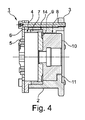
図4には、カムシャフト調整器の作動装置1のさらに発展された実施形態が示されている。この場合には、軸方向で入力車3と作動伝動装置4、つまりウェーブ伝動装置との間に位置する滑り軸受装置8に対して付加的に、別の滑り軸受装置14が設けられていることが判る。この滑り軸受装置14を用いて、出力リングギヤ7は、図5に示した構造と比較可能に、ハウジング2内にスライド式に支持されている。したがって、特に安定した二重の滑り軸受装置8,14が与えられている。第2の滑り軸受装置14の直径は、第1の滑り軸受装置8の直径よりも大きい。それと同時に、作動装置1の軸方向における第1の一次的な滑り軸受装置8の延在長さは、同じ方向で測定された、第2の二次的な滑り軸受装置14の延在長さよりも大きい。
FIG. 4 shows a further developed embodiment of the actuating device 1 of the camshaft regulator. In this case, another
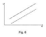
図6に示した線図は、図1に示した作動装置1と、図5に示した構造との間の比較に関するものである。ここで、「K」は、入力車3を駆動する引張手段、つまりチェーンにおいて作用するチェーン力を表す。「L」によって、滑り軸受装置8における軸受摩擦が表されている。図6における上側の一点鎖線は、図5に示した、特許請求されていない構造に関するものである。下側の破線は、図1に示した実施形態に関するものである。全ての作動状態において、図1に示した実施形態の軸受摩擦が減じられていることが良く判る。図4に示した実施形態と、図5に示した構造との間の比較にも、原理的には同じ関係性が云える。
The diagram shown in FIG. 6 relates to a comparison between the actuating device 1 shown in FIG. 1 and the structure shown in FIG. Here, "K" represents a tension means for driving the
1 作動装置
2 ハウジング
3 入力車
4 作動伝動装置
5 作動軸
6 入力リングギヤ
7 出力リングギヤ
8 第1の滑り軸受装置
9 フランジ
10 出力エレメント
11 伝動装置構成部分
12 軸方向溝
13 環状の溝
14 第2の滑り軸受装置
lk てこ腕長さ
K チェーン力
1
Claims (10)
ハウジング(2)と、
該ハウジング(2)に結合された入力車(3)と、
作動伝動装置(4)と、
駆動されるべきシャフトとの結合のために設けられた出力エレメント(10)と、
前記ハウジング(2)内に前記出力エレメント(10)を支持するために設けられた滑り軸受装置(8)と、
を備えた作動装置において、
前記出力エレメント(10)は、該出力エレメント(10)に相対回動不能に結合されかつ該出力エレメント(10)を半径方向で超えて突出しているフランジ(9)を、駆動されるべきシャフトの軸方向で見て、前記作動伝動装置(4)と前記入力車(3)との間に有しており、前記滑り軸受装置(8)は、前記フランジ(9)に隣接して前記入力車(3)の側に配置されていることを特徴とする、内燃機関のシャフトの作動装置。 It is an operating device for the shaft of an internal combustion engine.
Housing (2) and
The input wheel (3) coupled to the housing (2) and
Operation transmission device (4) and
An output element (10) provided for coupling with the shaft to be driven,
A slide bearing device (8) provided in the housing (2) to support the output element (10), and
In the operating device equipped with
The output element (10) is a shaft of a shaft to be driven by a flange (9) which is connected to the output element (10) so as to be relatively non-rotatable and protrudes beyond the output element (10) in a radial direction. Seen in the axial direction, it is held between the operation transmission device (4) and the input vehicle (3), and the slide bearing device (8) is adjacent to the flange (9) and is the input vehicle. An actuating device for a shaft of an internal combustion engine, characterized in that it is arranged on the side of (3) .
Applications Claiming Priority (3)
| Application Number | Priority Date | Filing Date | Title |
|---|---|---|---|
| DE102015217296.1 | 2015-09-10 | ||
| DE102015217296 | 2015-09-10 | ||
| PCT/DE2016/200420 WO2017041801A1 (en) | 2015-09-10 | 2016-09-07 | Camshaft adjuster |
Publications (2)
| Publication Number | Publication Date |
|---|---|
| JP2018530695A JP2018530695A (en) | 2018-10-18 |
| JP6800959B2 true JP6800959B2 (en) | 2020-12-16 |
Family
ID=57003300
Family Applications (1)
| Application Number | Title | Priority Date | Filing Date |
|---|---|---|---|
| JP2018512528A Active JP6800959B2 (en) | 2015-09-10 | 2016-09-07 | Camshaft regulator |
Country Status (5)
| Country | Link |
|---|---|
| EP (1) | EP3347578B1 (en) |
| JP (1) | JP6800959B2 (en) |
| CN (1) | CN108026799B (en) |
| DE (1) | DE102016216927A1 (en) |
| WO (1) | WO2017041801A1 (en) |
Families Citing this family (4)
| Publication number | Priority date | Publication date | Assignee | Title |
|---|---|---|---|---|
| US10287932B2 (en) * | 2016-09-19 | 2019-05-14 | Schaeffler Technologies AG & Co. KG | Camshaft phasing system including idler gear phaser for internal combustion engines |
| DE102017115882B4 (en) | 2017-07-14 | 2023-11-09 | Schaeffler Technologies AG & Co. KG | Electric camshaft adjuster for variable adjustment of the valve timing of an internal combustion engine |
| DE102017128423A1 (en) | 2017-11-30 | 2019-06-06 | Schaeffler Technologies AG & Co. KG | The wave gear |
| DE102018128930B4 (en) | 2018-11-19 | 2023-06-29 | Schaeffler Technologies AG & Co. KG | Waveform gear, method for manufacturing a strainwave gear and camshaft adjuster with a strainwave gear |
Family Cites Families (11)
| Publication number | Priority date | Publication date | Assignee | Title |
|---|---|---|---|---|
| US7089897B2 (en) * | 2002-07-11 | 2006-08-15 | Ina-Schaeffler Kg | Electrically driven camshaft adjuster |
| DE102004038681B4 (en) | 2004-08-10 | 2017-06-01 | Schaeffler Technologies AG & Co. KG | Electromotive camshaft adjuster |
| JP4390078B2 (en) * | 2005-09-05 | 2009-12-24 | 株式会社デンソー | Valve timing adjustment device |
| JP4900286B2 (en) * | 2008-03-04 | 2012-03-21 | 株式会社デンソー | Valve timing adjustment device |
| JP5288311B2 (en) * | 2009-04-03 | 2013-09-11 | Ntn株式会社 | Variable valve timing device |
| US8555836B2 (en) * | 2010-12-10 | 2013-10-15 | Delphi Technologies, Inc. | Electric drive camshaft phaser with torque rate limit at travel stops |
| US8516983B2 (en) | 2011-09-30 | 2013-08-27 | Delphi Technologies, Inc. | Harmonic drive camshaft phaser with a harmonic drive ring to prevent ball cage deflection |
| JP2013167181A (en) * | 2012-02-15 | 2013-08-29 | Hitachi Automotive Systems Ltd | Valve timing control apparatus for internal combustion engine |
| JP2014074388A (en) * | 2012-10-05 | 2014-04-24 | Denso Corp | Valve timing adjustment device |
| CN104838096A (en) * | 2012-12-10 | 2015-08-12 | 博格华纳公司 | Electric motor driven simple planetary cam phaser |
| JP5862696B2 (en) * | 2014-01-29 | 2016-02-16 | 株式会社日本自動車部品総合研究所 | Valve timing adjustment device |
-
2016
- 2016-09-07 WO PCT/DE2016/200420 patent/WO2017041801A1/en active Application Filing
- 2016-09-07 EP EP16770885.8A patent/EP3347578B1/en active Active
- 2016-09-07 JP JP2018512528A patent/JP6800959B2/en active Active
- 2016-09-07 DE DE102016216927.0A patent/DE102016216927A1/en not_active Withdrawn
- 2016-09-07 CN CN201680050942.8A patent/CN108026799B/en active Active
Also Published As
| Publication number | Publication date |
|---|---|
| EP3347578B1 (en) | 2019-06-19 |
| DE102016216927A1 (en) | 2017-03-16 |
| JP2018530695A (en) | 2018-10-18 |
| CN108026799A (en) | 2018-05-11 |
| CN108026799B (en) | 2020-06-30 |
| WO2017041801A1 (en) | 2017-03-16 |
| EP3347578A1 (en) | 2018-07-18 |
Similar Documents
| Publication | Publication Date | Title |
|---|---|---|
| JP6800959B2 (en) | Camshaft regulator | |
| JP2021021479A (en) | Clutch device | |
| JP6820321B2 (en) | Transmission device with elastic gears | |
| US8622037B2 (en) | Harmonic drive camshaft phaser with a compact drive sprocket | |
| US20190323577A1 (en) | Damper device | |
| JP2009197981A (en) | Transmission | |
| JP2018505363A (en) | Belt pulley decoupler | |
| WO2016093064A1 (en) | Transmission mechanism | |
| JP4929206B2 (en) | transmission | |
| JP5139209B2 (en) | Variable valve timing device | |
| US7614372B2 (en) | Bias spring arbor for a camshaft phaser | |
| JP5180931B2 (en) | Belt type continuously variable transmission | |
| JP2010038184A (en) | Transmission | |
| JP2015021558A (en) | Continuously variable transmission | |
| JP2014196780A (en) | V-belt type stepless transmission | |
| JP6180993B2 (en) | Continuously variable transmission | |
| JP2014196784A (en) | V-belt type continuously variable transmission | |
| JP6036282B2 (en) | Actuator | |
| FR3049019A1 (en) | CAM PATH TORSION FILTRATION MECHANISM | |
| JP2008082343A (en) | Valve timing control device for internal combustion engine | |
| JP6020139B2 (en) | Actuator | |
| US8601904B2 (en) | Force transmission assembly and a control assembly including such an assembly | |
| JP6081953B2 (en) | Power transmission device for vehicle | |
| WO2017135047A1 (en) | Belt-type continuously variable transmission | |
| JP2005061357A (en) | Governor device |
Legal Events
| Date | Code | Title | Description |
|---|---|---|---|
| A621 | Written request for application examination |
Free format text: JAPANESE INTERMEDIATE CODE: A621 Effective date: 20190904 |
|
| A131 | Notification of reasons for refusal |
Free format text: JAPANESE INTERMEDIATE CODE: A131 Effective date: 20200618 |
|
| A521 | Request for written amendment filed |
Free format text: JAPANESE INTERMEDIATE CODE: A523 Effective date: 20200910 |
|
| TRDD | Decision of grant or rejection written | ||
| A01 | Written decision to grant a patent or to grant a registration (utility model) |
Free format text: JAPANESE INTERMEDIATE CODE: A01 Effective date: 20201027 |
|
| A61 | First payment of annual fees (during grant procedure) |
Free format text: JAPANESE INTERMEDIATE CODE: A61 Effective date: 20201125 |
|
| R150 | Certificate of patent or registration of utility model |
Ref document number: 6800959 Country of ref document: JP Free format text: JAPANESE INTERMEDIATE CODE: R150 |
|
| R250 | Receipt of annual fees |
Free format text: JAPANESE INTERMEDIATE CODE: R250 |