JP6800102B2 - Fluid level sensor that combines capacitance and conductivity - Google Patents
Fluid level sensor that combines capacitance and conductivity Download PDFInfo
- Publication number
- JP6800102B2 JP6800102B2 JP2017134541A JP2017134541A JP6800102B2 JP 6800102 B2 JP6800102 B2 JP 6800102B2 JP 2017134541 A JP2017134541 A JP 2017134541A JP 2017134541 A JP2017134541 A JP 2017134541A JP 6800102 B2 JP6800102 B2 JP 6800102B2
- Authority
- JP
- Japan
- Prior art keywords
- electrode
- fluid
- signal
- ink
- drive
- Prior art date
- Legal status (The legal status is an assumption and is not a legal conclusion. Google has not performed a legal analysis and makes no representation as to the accuracy of the status listed.)
- Active
Links
- 239000012530 fluid Substances 0.000 title claims description 58
- 238000001514 detection method Methods 0.000 claims description 34
- 239000002184 metal Substances 0.000 claims description 9
- 230000001360 synchronised effect Effects 0.000 claims description 2
- 239000000976 ink Substances 0.000 description 55
- 239000000523 sample Substances 0.000 description 18
- 238000010586 diagram Methods 0.000 description 4
- 239000010408 film Substances 0.000 description 4
- 239000007788 liquid Substances 0.000 description 3
- 239000003990 capacitor Substances 0.000 description 2
- 239000000463 material Substances 0.000 description 2
- 239000000872 buffer Substances 0.000 description 1
- 230000003750 conditioning effect Effects 0.000 description 1
- 230000004069 differentiation Effects 0.000 description 1
- 238000010438 heat treatment Methods 0.000 description 1
- 238000004519 manufacturing process Methods 0.000 description 1
- 230000003287 optical effect Effects 0.000 description 1
- 239000000049 pigment Substances 0.000 description 1
- 239000010409 thin film Substances 0.000 description 1
- 239000012463 white pigment Substances 0.000 description 1
Images


Classifications
-
- B—PERFORMING OPERATIONS; TRANSPORTING
- B41—PRINTING; LINING MACHINES; TYPEWRITERS; STAMPS
- B41J—TYPEWRITERS; SELECTIVE PRINTING MECHANISMS, i.e. MECHANISMS PRINTING OTHERWISE THAN FROM A FORME; CORRECTION OF TYPOGRAPHICAL ERRORS
- B41J2/00—Typewriters or selective printing mechanisms characterised by the printing or marking process for which they are designed
- B41J2/005—Typewriters or selective printing mechanisms characterised by the printing or marking process for which they are designed characterised by bringing liquid or particles selectively into contact with a printing material
- B41J2/01—Ink jet
- B41J2/07—Ink jet characterised by jet control
- B41J2/125—Sensors, e.g. deflection sensors
-
- B—PERFORMING OPERATIONS; TRANSPORTING
- B41—PRINTING; LINING MACHINES; TYPEWRITERS; STAMPS
- B41J—TYPEWRITERS; SELECTIVE PRINTING MECHANISMS, i.e. MECHANISMS PRINTING OTHERWISE THAN FROM A FORME; CORRECTION OF TYPOGRAPHICAL ERRORS
- B41J2/00—Typewriters or selective printing mechanisms characterised by the printing or marking process for which they are designed
- B41J2/005—Typewriters or selective printing mechanisms characterised by the printing or marking process for which they are designed characterised by bringing liquid or particles selectively into contact with a printing material
- B41J2/01—Ink jet
- B41J2/17—Ink jet characterised by ink handling
- B41J2/175—Ink supply systems ; Circuit parts therefor
- B41J2/17566—Ink level or ink residue control
-
- G—PHYSICS
- G01—MEASURING; TESTING
- G01F—MEASURING VOLUME, VOLUME FLOW, MASS FLOW OR LIQUID LEVEL; METERING BY VOLUME
- G01F23/00—Indicating or measuring liquid level or level of fluent solid material, e.g. indicating in terms of volume or indicating by means of an alarm
- G01F23/22—Indicating or measuring liquid level or level of fluent solid material, e.g. indicating in terms of volume or indicating by means of an alarm by measuring physical variables, other than linear dimensions, pressure or weight, dependent on the level to be measured, e.g. by difference of heat transfer of steam or water
-
- B—PERFORMING OPERATIONS; TRANSPORTING
- B41—PRINTING; LINING MACHINES; TYPEWRITERS; STAMPS
- B41J—TYPEWRITERS; SELECTIVE PRINTING MECHANISMS, i.e. MECHANISMS PRINTING OTHERWISE THAN FROM A FORME; CORRECTION OF TYPOGRAPHICAL ERRORS
- B41J2/00—Typewriters or selective printing mechanisms characterised by the printing or marking process for which they are designed
- B41J2/005—Typewriters or selective printing mechanisms characterised by the printing or marking process for which they are designed characterised by bringing liquid or particles selectively into contact with a printing material
- B41J2/01—Ink jet
- B41J2/015—Ink jet characterised by the jet generation process
- B41J2/04—Ink jet characterised by the jet generation process generating single droplets or particles on demand
- B41J2/045—Ink jet characterised by the jet generation process generating single droplets or particles on demand by pressure, e.g. electromechanical transducers
- B41J2/04501—Control methods or devices therefor, e.g. driver circuits, control circuits
- B41J2/0451—Control methods or devices therefor, e.g. driver circuits, control circuits for detecting failure, e.g. clogging, malfunctioning actuator
-
- B—PERFORMING OPERATIONS; TRANSPORTING
- B41—PRINTING; LINING MACHINES; TYPEWRITERS; STAMPS
- B41J—TYPEWRITERS; SELECTIVE PRINTING MECHANISMS, i.e. MECHANISMS PRINTING OTHERWISE THAN FROM A FORME; CORRECTION OF TYPOGRAPHICAL ERRORS
- B41J2/00—Typewriters or selective printing mechanisms characterised by the printing or marking process for which they are designed
- B41J2/005—Typewriters or selective printing mechanisms characterised by the printing or marking process for which they are designed characterised by bringing liquid or particles selectively into contact with a printing material
- B41J2/01—Ink jet
- B41J2/015—Ink jet characterised by the jet generation process
- B41J2/04—Ink jet characterised by the jet generation process generating single droplets or particles on demand
- B41J2/045—Ink jet characterised by the jet generation process generating single droplets or particles on demand by pressure, e.g. electromechanical transducers
- B41J2/04501—Control methods or devices therefor, e.g. driver circuits, control circuits
- B41J2/04555—Control methods or devices therefor, e.g. driver circuits, control circuits detecting current
-
- B—PERFORMING OPERATIONS; TRANSPORTING
- B41—PRINTING; LINING MACHINES; TYPEWRITERS; STAMPS
- B41J—TYPEWRITERS; SELECTIVE PRINTING MECHANISMS, i.e. MECHANISMS PRINTING OTHERWISE THAN FROM A FORME; CORRECTION OF TYPOGRAPHICAL ERRORS
- B41J2/00—Typewriters or selective printing mechanisms characterised by the printing or marking process for which they are designed
- B41J2/005—Typewriters or selective printing mechanisms characterised by the printing or marking process for which they are designed characterised by bringing liquid or particles selectively into contact with a printing material
- B41J2/01—Ink jet
- B41J2/17—Ink jet characterised by ink handling
- B41J2/175—Ink supply systems ; Circuit parts therefor
- B41J2/17503—Ink cartridges
- B41J2/17513—Inner structure
-
- G—PHYSICS
- G01—MEASURING; TESTING
- G01F—MEASURING VOLUME, VOLUME FLOW, MASS FLOW OR LIQUID LEVEL; METERING BY VOLUME
- G01F23/00—Indicating or measuring liquid level or level of fluent solid material, e.g. indicating in terms of volume or indicating by means of an alarm
- G01F23/22—Indicating or measuring liquid level or level of fluent solid material, e.g. indicating in terms of volume or indicating by means of an alarm by measuring physical variables, other than linear dimensions, pressure or weight, dependent on the level to be measured, e.g. by difference of heat transfer of steam or water
- G01F23/24—Indicating or measuring liquid level or level of fluent solid material, e.g. indicating in terms of volume or indicating by means of an alarm by measuring physical variables, other than linear dimensions, pressure or weight, dependent on the level to be measured, e.g. by difference of heat transfer of steam or water by measuring variations of resistance of resistors due to contact with conductor fluid
- G01F23/241—Indicating or measuring liquid level or level of fluent solid material, e.g. indicating in terms of volume or indicating by means of an alarm by measuring physical variables, other than linear dimensions, pressure or weight, dependent on the level to be measured, e.g. by difference of heat transfer of steam or water by measuring variations of resistance of resistors due to contact with conductor fluid for discrete levels
-
- G—PHYSICS
- G01—MEASURING; TESTING
- G01F—MEASURING VOLUME, VOLUME FLOW, MASS FLOW OR LIQUID LEVEL; METERING BY VOLUME
- G01F23/00—Indicating or measuring liquid level or level of fluent solid material, e.g. indicating in terms of volume or indicating by means of an alarm
- G01F23/22—Indicating or measuring liquid level or level of fluent solid material, e.g. indicating in terms of volume or indicating by means of an alarm by measuring physical variables, other than linear dimensions, pressure or weight, dependent on the level to be measured, e.g. by difference of heat transfer of steam or water
- G01F23/26—Indicating or measuring liquid level or level of fluent solid material, e.g. indicating in terms of volume or indicating by means of an alarm by measuring physical variables, other than linear dimensions, pressure or weight, dependent on the level to be measured, e.g. by difference of heat transfer of steam or water by measuring variations of capacity or inductance of capacitors or inductors arising from the presence of liquid or fluent solid material in the electric or electromagnetic fields
- G01F23/263—Indicating or measuring liquid level or level of fluent solid material, e.g. indicating in terms of volume or indicating by means of an alarm by measuring physical variables, other than linear dimensions, pressure or weight, dependent on the level to be measured, e.g. by difference of heat transfer of steam or water by measuring variations of capacity or inductance of capacitors or inductors arising from the presence of liquid or fluent solid material in the electric or electromagnetic fields by measuring variations in capacitance of capacitors
- G01F23/265—Indicating or measuring liquid level or level of fluent solid material, e.g. indicating in terms of volume or indicating by means of an alarm by measuring physical variables, other than linear dimensions, pressure or weight, dependent on the level to be measured, e.g. by difference of heat transfer of steam or water by measuring variations of capacity or inductance of capacitors or inductors arising from the presence of liquid or fluent solid material in the electric or electromagnetic fields by measuring variations in capacitance of capacitors for discrete levels
-
- G—PHYSICS
- G01—MEASURING; TESTING
- G01F—MEASURING VOLUME, VOLUME FLOW, MASS FLOW OR LIQUID LEVEL; METERING BY VOLUME
- G01F23/00—Indicating or measuring liquid level or level of fluent solid material, e.g. indicating in terms of volume or indicating by means of an alarm
- G01F23/22—Indicating or measuring liquid level or level of fluent solid material, e.g. indicating in terms of volume or indicating by means of an alarm by measuring physical variables, other than linear dimensions, pressure or weight, dependent on the level to be measured, e.g. by difference of heat transfer of steam or water
- G01F23/26—Indicating or measuring liquid level or level of fluent solid material, e.g. indicating in terms of volume or indicating by means of an alarm by measuring physical variables, other than linear dimensions, pressure or weight, dependent on the level to be measured, e.g. by difference of heat transfer of steam or water by measuring variations of capacity or inductance of capacitors or inductors arising from the presence of liquid or fluent solid material in the electric or electromagnetic fields
- G01F23/263—Indicating or measuring liquid level or level of fluent solid material, e.g. indicating in terms of volume or indicating by means of an alarm by measuring physical variables, other than linear dimensions, pressure or weight, dependent on the level to be measured, e.g. by difference of heat transfer of steam or water by measuring variations of capacity or inductance of capacitors or inductors arising from the presence of liquid or fluent solid material in the electric or electromagnetic fields by measuring variations in capacitance of capacitors
- G01F23/266—Indicating or measuring liquid level or level of fluent solid material, e.g. indicating in terms of volume or indicating by means of an alarm by measuring physical variables, other than linear dimensions, pressure or weight, dependent on the level to be measured, e.g. by difference of heat transfer of steam or water by measuring variations of capacity or inductance of capacitors or inductors arising from the presence of liquid or fluent solid material in the electric or electromagnetic fields by measuring variations in capacitance of capacitors measuring circuits therefor
-
- B—PERFORMING OPERATIONS; TRANSPORTING
- B41—PRINTING; LINING MACHINES; TYPEWRITERS; STAMPS
- B41J—TYPEWRITERS; SELECTIVE PRINTING MECHANISMS, i.e. MECHANISMS PRINTING OTHERWISE THAN FROM A FORME; CORRECTION OF TYPOGRAPHICAL ERRORS
- B41J2/00—Typewriters or selective printing mechanisms characterised by the printing or marking process for which they are designed
- B41J2/005—Typewriters or selective printing mechanisms characterised by the printing or marking process for which they are designed characterised by bringing liquid or particles selectively into contact with a printing material
- B41J2/01—Ink jet
- B41J2/17—Ink jet characterised by ink handling
- B41J2/175—Ink supply systems ; Circuit parts therefor
- B41J2/17566—Ink level or ink residue control
- B41J2002/17579—Measuring electrical impedance for ink level indication
-
- Y—GENERAL TAGGING OF NEW TECHNOLOGICAL DEVELOPMENTS; GENERAL TAGGING OF CROSS-SECTIONAL TECHNOLOGIES SPANNING OVER SEVERAL SECTIONS OF THE IPC; TECHNICAL SUBJECTS COVERED BY FORMER USPC CROSS-REFERENCE ART COLLECTIONS [XRACs] AND DIGESTS
- Y02—TECHNOLOGIES OR APPLICATIONS FOR MITIGATION OR ADAPTATION AGAINST CLIMATE CHANGE
- Y02P—CLIMATE CHANGE MITIGATION TECHNOLOGIES IN THE PRODUCTION OR PROCESSING OF GOODS
- Y02P70/00—Climate change mitigation technologies in the production process for final industrial or consumer products
- Y02P70/10—Greenhouse gas [GHG] capture, material saving, heat recovery or other energy efficient measures, e.g. motor control, characterised by manufacturing processes, e.g. for rolling metal or metal working
Description
本開示は、流体レベルセンサに関し、より具体的には、レベルを検知するために静電容量又は導電率を使用する流体レベルセンサに関する。 The present disclosure relates to fluid level sensors, and more specifically to fluid level sensors that use capacitance or conductivity to detect levels.
多くの異なる装置は、容器内の流体レベルを検知するために流体レベルセンサを使用している。検知は、例えば、自動化された液体補充を開始することができたり、ステータスレポートに含まれることができたり、レベルが低くなって補充が必要な場合にのみレポートすることができたりする。そのような用途の1つは、印刷システムにおいて使用されるインク容器のレベルを検知することを含む。これは1つの例であるが、インク検知用途は、電流センサによる問題のいくつかを示している。 Many different devices use fluid level sensors to detect the fluid level in the vessel. Detection can, for example, initiate automated fluid refilling, be included in status reports, or report only when the level is low and refilling is required. One such application involves detecting the level of an ink container used in a printing system. This is just one example, but ink detection applications show some of the problems with current sensors.
この領域において発生する1つの問題は、同様に幅広いインクのアレイを使用する幅広い印刷システムに由来する。インクは、多くの異なる材料と、全て異なる特性を有するこれらの材料の多くの異なる組み合わせとから構成されることができる。例えば、異なるインクは、異なる導電性を有する。導電性ベースのインクレベルセンサは、特定の製品において使用される特定のインク用に設計されたときに良好に機能した。例えば、これらのインクのいくつかは、製造ロット及び使用条件にわたって10:1の導電率範囲を有する。しかしながら、複数のインク化学をカバーするより広い用途において、導電率の範囲は、1000000:1を超えることがある。 One problem that arises in this area stems from a wide range of printing systems that also use a wide array of inks. Inks can be composed of many different materials and many different combinations of these materials, all having different properties. For example, different inks have different conductivity. Conductivity-based ink level sensors worked well when designed for a particular ink used in a particular product. For example, some of these inks have a conductivity range of 10: 1 across production lots and conditions of use. However, in a wider range of applications covering multiple ink chemistries, the conductivity range can exceed 1000000: 1.
一部の製品は、自己発熱サーミスタプローブを使用している。しかしながら、これらは、加熱されたインクが入ったときに誤った空読みを示すことがある。プローブからの熱はまた、特定のUV感受性インクを劣化させることもある。おそらくよりも、1つの種類のサーミスタプローブは、インクの種類及び特性の範囲にわたって動作しない。 Some products use self-heating thermistor probes. However, they may show false readings when heated ink enters. The heat from the probe can also degrade certain UV sensitive inks. Perhaps more than one type of thermistor probe does not work over a range of ink types and properties.
他の製品は、光学式インクレベル検知プローブを使用している。これらのプローブは、いくつかの溶融可能インクに使用される高温で劣化することがある。それらはまた、インク顔料によってコーティングされることがあり、一般に、高充填白色顔料インクにおいて満杯信号と空信号との間の信号の差別化が不十分である。 Other products use optical ink level detection probes. These probes can deteriorate at the high temperatures used in some meltable inks. They may also be coated with ink pigments, which generally result in inadequate signal differentiation between full and empty signals in highly filled white pigment inks.
さらに他の製品は、容量性インクレベル検知を使用している。これは、非導電性インクから適度に導電性のインクまで良好に機能する。特に金属容器又はタンクにおける高導電性インクは、問題を引き起こすことがある。プローブを被覆するインクの薄膜は、誤った満杯読み取りを引き起こすことがある。インクがプローブ信号を容器ハウジングに短絡させると、誤った空読みがまた発生する可能性がある。 Yet other products use capacitive ink level detection. It works well from non-conductive inks to moderately conductive inks. Highly conductive inks, especially in metal containers or tanks, can cause problems. A thin film of ink that coats the probe can cause false full reads. False blank readings can also occur if the ink shorts the probe signal to the container housing.
広範囲の温度にわたって異なる種類のインクにおいて動作することができる単一種類のセンサを提供して使用する能力は有用であろう。 The ability to provide and use a single type of sensor capable of operating with different types of ink over a wide range of temperatures would be useful.
1つの実施形態は、第1の電極と、第2の電極と、電極がハウジングから延在するように第1の電極及び第2の電極を含むハウジングと、第1の電極と第2の電極との間の露出金属と、流体が容器内に存在するときに第1の電極が流体の存在を検知するか又は駆動信号が流体の存在を検知するように第2の電極に電気的に接続された駆動信号とを有する流体センサから構成される。 One embodiment includes a first electrode, a second electrode, a housing that includes a first electrode and a second electrode such that the electrodes extend from the housing, and a first electrode and a second electrode. The exposed metal between and the first electrode is electrically connected to the second electrode so that the presence of the fluid is detected when the fluid is in the container or the drive signal detects the presence of the fluid. It is composed of a fluid sensor having a driven signal.
他の実施形態は、第1の電極と、第2の電極と、第1及び第2の電極を含むハウジングと、第2の電極に電気的に接続された駆動信号と、流体レベルを示すために第2の電極からの電流を測定する検知回路とを有する流体センサである。 Another embodiment is to indicate a first electrode, a second electrode, a housing containing the first and second electrodes, a drive signal electrically connected to the second electrode, and a fluid level. It is a fluid sensor having a detection circuit for measuring the current from the second electrode.
図1は、流体容器ハウジング10の実施形態を示している。この特定の実施形態及び本願明細書における議論において、多くの例は、プリンタにおいて使用されるインク容器を含む。しかしながら、本願明細書における実施形態は、多くの異なる種類の流体レベルセンサに適用されることに留意すべきである。
FIG. 1 shows an embodiment of the
流体容器ハウジング10は、インク又は他の流体12のレベルを保持する容器16を含む。流体レベルセンサ14は、より詳細に後述するように、2つの電極を延在するそれ自身のハウジングを有する。電極は、流体内に延在している。電極から検出された結果として生じる電圧及び電流は、システムが流体の有無を判定し、検知システムの性質に応じて、利用可能なインクの量を判定するのを可能とする。
The
図2の流体レベルセンサの実施形態は、2つの部分を有する。第1の部分は、センサハウジング内の非常に小さな回路基板であり、第2の部分は、典型的には、メインシステムの流体システムエレクトロニクスに存在する。第2の部分は、ハウジング10内、又はプリンタ若しくは流体分配システム自体の電子モジュール内に存在してもよい。図2の実施形態において、プローブ回路22は、センサハウジング内に存在し、駆動検知回路20及び検知回路24は、センサハウジングから離れて存在する。
The embodiment of the fluid level sensor of FIG. 2 has two parts. The first part is a very small circuit board in the sensor housing and the second part is typically present in the fluid system electronics of the main system. The second portion may be present in the
駆動検知回路20は、上部電極に電気的に接続され且つ駆動信号DRIVEを提供する駆動信号を生成する、図4に示される選択(SEL)信号及びイネーブル(EN)信号を受信する。駆動検知回路20はまた、過電流がDRIVE信号から引き出されたときを示す駆動_電流_検知信号を提供する。プローブ22は、容器内のインクに基づいて電圧を生成し、検知回路24に対して得られた電圧Voutを送信する。Voutの振幅は、インクがインク容量又は導電率に起因してプローブ22の双方の電極に接触しているとき(満杯状態)に増加する。接地された金属容器内の高導電性インクの場合、Voutは、DRIVE信号の負荷に起因して低くなることがある。この場合、駆動_電流_検知は、インク満杯状態をトリガする。検知回路は、Voutにおける高振幅信号又は駆動_電流_検知におけるハイレベルのいずれかの検知に基づいてインクレベル信号を生成する。
The
流体が高導電性を有する場合、典型的な容量性又は導電性流体レベル検知システムのようにVoutを単独で使用することによって問題が生じる。容器内に低導電率の液体が存在する場合、駆動信号は、容量的に又は導電的に検知電極に結合し、インク満杯信号をもたらす。本実施形態における高導電性インクの場合、現在利用可能なインクセンサは、誤った空又は満杯読み取りを生じることがある。本願明細書における実施形態において、高導電率のインクが上部電極に到達すると、特に金属容器の場合には上部電極をグラウンドに短絡させる。この上部電極における高負荷電流はまた、検知されて満杯読み取りを生じさせる。いくつかの実施形態において、高導電性インクは、1センチメートルあたり500マイクロシーメンスを超える導電性のものであり、より低い導電性のものは、低導電性インクと考えられる。高導電率及び低導電率の閾値は、システム設計者に委ねることができる。 If the fluid has high conductivity, problems arise with the use of Vout alone, as in typical capacitive or conductive fluid level detection systems. When a low conductivity liquid is present in the container, the drive signal is capacitively or conductively coupled to the detection electrode, resulting in an ink full signal. For highly conductive inks in this embodiment, currently available ink sensors can result in erroneous empty or full readings. In the embodiment of the present specification, when the high conductivity ink reaches the upper electrode, the upper electrode is short-circuited to the ground, especially in the case of a metal container. The high load current at this top electrode is also detected and causes a full read. In some embodiments, the highly conductive ink is considered to be more than 500 microsiemens per centimeter, and the lower conductive ink is considered to be a low conductive ink. The high conductivity and low conductivity thresholds can be left to the system designer.
空の状態において、流体の膜は、レベル検知プローブアセンブリを被覆したままであることがある。高導電率の液体の場合、この膜は、電極間に導電路を形成する可能性があり、誤った満杯読み取りを生じる可能性がある。この問題を回避するために、露出した接地金属40が2つの電極間に介在される。残存インク膜の導電性は、グラウンドに分路され、誤った満杯読み取りを防止する。
In the empty state, the fluid film may remain coated on the level detection probe assembly. For high conductivity liquids, this film can form conductive paths between the electrodes, which can lead to false full readings. To avoid this problem, an exposed
図3は、センサについての回路の実施形態を示している。上述したように、「上部」電極が容器内のいかなる流体に対しても下部電極よりも高く配置されるように2つの電極が配置されている。上部電極は、図4に関して後述する駆動回路から駆動信号を受信する。インク12は、信号を下部電極に結合させる。オペアンプOP109は、高インピーダンス検知電極信号をバッファリングする。P5は、オペアンプOP109に電力を供給するための正電圧源である。C103、R101、C102、R105、C106並びにRCフィルタC107及びR104などの様々なコンデンサ及び抵抗は、出力信号Voutについての信号調整及び制御を提供する。 FIG. 3 shows an embodiment of a circuit for a sensor. As mentioned above, the two electrodes are arranged so that the "upper" electrode is located higher than the lower electrode for any fluid in the vessel. The upper electrode receives a drive signal from a drive circuit described later with respect to FIG. The ink 12 couples the signal to the lower electrode. The operational amplifier OP109 buffers the high impedance detection electrode signal. P5 is a positive voltage source for supplying electric power to the operational amplifier OP109. Various capacitors and resistors such as C103, R101, C102, R105, C106 and RC filters C107 and R104 provide signal conditioning and control for the output signal Vout.
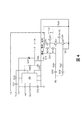
図4は、図3のプローブ回路と関連して使用するための駆動及び検知回路の1つの実施形態を示している。図4の駆動及び検知回路は、インクの導電性に依存して、インクを介して容量的に又は導電的に結合する又はグラウンドに短絡させることができる2つの電極を有する任意のプローブ回路とともに使用されることができる。これは、そのような回路の単なる一例に過ぎない。図4において、回路の下部ブロックは、駆動信号を生成し、上部ブロックは、Vout信号を受信し、印刷ヘッド又は他の流体分配システムに対して最終的に送信されるインク_レベル信号を生成する。 FIG. 4 shows one embodiment of a drive and detection circuit for use in connection with the probe circuit of FIG. The drive and detection circuit of FIG. 4 is used with any probe circuit having two electrodes that can be capacitively or conductively coupled through the ink or shorted to ground, depending on the conductivity of the ink. Can be done. This is just one example of such a circuit. In FIG. 4, the lower block of the circuit produces a drive signal and the upper block receives a Vout signal and produces an ink_level signal that is ultimately transmitted to the printhead or other fluid distribution system. ..
駆動部は、選択信号SELを受信する。この実施形態において、SEL信号は、方形波からなる。また、SEL信号の2倍の周波数を有する同様に方形波からなるイネーブル信号ENも存在する。ENは、DRIVE及びVoutが落ち着いた後に、各SEL信号状態の後半中にのみアナログマルチプレクサ203にVoutをサンプリングさせる。SEL及びEN信号は、アナログマルチプレクサ203を制御する。SELが状態を(ハイからローに又はローからハイに)変化するたびに、ENは、そのSEL状態の前半について偽となり、アナログマルチプレクサ203を開回路にする。ロー状態のSELの後半において、アナログマルチプレクサ203は、Voutの容量結合バージョンであるR202をグラウンドに接続する。ハイ状態のSELの後半において、アナログマルチプレクサ203は、R208にR202を接続し、C210を充電又は放電させ、Voutの振幅によって判定されるレベルにインク_レベル信号をもたらす。DRIVE信号は、容器内の流体が満杯状態の高導電性インクでない限り、SEL信号の増幅されて反転されたバージョンである。回路ブロックは、SEL信号を増幅し、図3からの電極1に電気的に結合されるDRIVE信号を生成する。
The drive unit receives the selection signal SEL. In this embodiment, the SEL signal consists of a square wave. There is also an enable signal EN, which also has a square wave and has twice the frequency of the SEL signal. EN causes the
上述したように、DRIVE信号は、Vout信号を返すプローブ回路に供給される。図4の実施形態において、Vout信号は、インク_レベル信号を形成するために同期して整流される。50又は60Hzの電力線干渉などの他の周波数における過渡現象及びノイズ源を排除しながら、同期整流は、Voutの振幅を正確に測定する。Voutは、単投双極(STDP)アナログマルチプレクサ又はスイッチ203の入力1Zに容量結合される。マルチプレクサ203はまた、正電圧源P5及びグラウンドGNDとともに、EN及びSEL信号を受信する。マルチプレクサの出力は、1Y1及び1Y0である。
As described above, the DRIVE signal is supplied to the probe circuit that returns the Vout signal. In the embodiment of FIG. 4, the Vout signal is synchronously rectified to form an ink_level signal. Synchronous rectification accurately measures the amplitude of the Vout, eliminating transients and noise sources at other frequencies such as 50 or 60 Hz power line interference. The Vout is capacitively coupled to input 1Z of a single-throw bipolar (STDP) analog multiplexer or
出力1Y0は、DRIVEのハイ状態及びVoutのロー状態であるSELのロー状態の後半中にグラウンドに対して1Zを接続する。出力1Y1は、Voutのハイ状態の後半中に1Zに接続し、インク_レベル信号を形成するようにコンデンサC210へのその振幅をサンプリングする。インクが2つの電極を結合しない場合、Voutの振幅は低く、C210における低電圧及びインク_レベル信号をもたらす。インクが2つの電極をブリッジする場合、DRIVE信号を短絡させるようにそれほど導電性が高くなく、Voutにおける振幅は高くなり、C210における高電圧及びインク_レベル信号をもたらす。 Output 1Y0 connects 1Z to the ground during the latter half of the high state of DRIVE and the low state of SEL, which is the low state of Vout. Output 1Y1 connects to 1Z during the second half of the high state of Vout and samples its amplitude to capacitor C210 to form an ink_level signal. If the ink does not couple the two electrodes, the Vout amplitude is low, resulting in a low voltage and ink_level signal at C210. When the ink bridges the two electrodes, it is not very conductive as short-circuiting the DRIVE signal, the amplitude at Vout is high, resulting in a high voltage at C210 and an ink_level signal.
インクが高導電性インクである場合、DRIVEは、トランジスタQ222をオンにするのに十分な電流を引き込む。Q222のコレクタは、Vout信号の振幅が低い場合であっても、ダイオードD211及び抵抗R209を介して、満杯状態を示す高いインク_レベル信号を引き出す。そうでなければ、高導電性インクは短絡を生じさせ、信号は下部電極に決して到達することがなく、誤った空の読み取りをもたらす。 If the ink is a highly conductive ink, DRIVE draws enough current to turn on transistor Q222. The collector of Q222 draws a high ink_level signal indicating a full state through the diode D211 and the resistor R209 even when the amplitude of the Vout signal is low. Otherwise, the highly conductive ink will cause a short circuit and the signal will never reach the bottom electrode, resulting in an erroneous empty reading.
図5は、完全に組み立てられた流体レベルセンサの図を示している。図6は、流体レベルセンサの分解図を示している。この実施形態において、それは、接地された金属ハウジングインサート40と、インサートOリング42とから構成されている。電極44は、ハウジングインサートを介してインク内に挿入される。4本のラインは、任意の場所及び順序で生じることができる。本願明細書における実施形態において、ライン46は、駆動信号ラインであり、ライン48は、Voutラインである。ライン50は、接地線であり、ライン52は、正電圧ラインである。流体レベルセンサの他端は、本体Oリング54、本体56、ナット58及びコネクタ60である。
FIG. 5 shows a diagram of a fully assembled fluid level sensor. FIG. 6 shows an exploded view of the fluid level sensor. In this embodiment, it is composed of a grounded
電極は、インク内に挿入され、信号は、インク容器又は液体分配システムのシャーシの内外に送られる。いくつかの実施形態において、電極は、およそ長さが13mm、幅が2.2mmであり、それらの間に3mmの間隙があった。駆動及び検知電極パッドは、接地されたハウジングの外側2mmから電極の端部から0.1mmまで延在している。この特定の幾何学的形状は、一方の電極から他方の電極への途中で接地されたハウジング金属上を必ず通過しなければならないいかなる残存インク膜も除いて、電極間のインクブリッジを防止するように設計されている。駆動信号は、9Vのピーク・ツー・ピーク交流電圧である。
Electrodes are inserted into the ink and signals are sent inside and outside the ink container or chassis of the liquid distribution system. In some embodiments, the electrodes were approximately 13 mm in length and 2.2 mm in width, with a gap of 3 mm between them. The drive and detection electrode pads extend from 2 mm outside the grounded housing to 0.1 mm from the end of the electrodes. This particular geometry prevents ink bridging between the electrodes, except for any residual ink film that must pass over the grounded housing metal on the way from one electrode to the other. Is designed for. The drive signal is a peak-to-peak AC voltage of 9V.
Claims (13)
第2の電極と、
前記第1及び第2の電極を収容するハウジングと、
前記第2の電極に電気的に接続される駆動信号を生成する駆動検知回路と、
前記第2の電極からの電流を測定するための検知回路であって、流体レベルを示す信号を生成し、駆動検知信号を受信して、前記第2の電極からの電流が伝導性インクにより低レベルを示す場合に、前記駆動検知信号が高レベルを示す信号を生成する検知回路と
を備える流体センサ。 With the first electrode
With the second electrode
A housing for accommodating the first and second electrodes and
A drive detection circuit that generates a drive signal that is electrically connected to the second electrode ,
A detection circuit for measuring the current from the previous SL second electrode, and generates a signal indicating the fluid level, receives the drive detection signal, current from the second electrode by conductive ink A fluid sensor including a detection circuit that generates a signal indicating a high level when the drive detection signal indicates a low level.
第2の電極と、
前記電極がハウジングから延在するように、前記第1及び第2の電極を収容し、流体に入れられるハウジングと、
前記第1及び前記第2の電極の間に設けられる一つの露出金属であって、グラウンドに接地され、前記流体にさらされて配置された露出金属と、
前記第2の電極に電気的に接続される駆動信号を生成する駆動回路であって、前記駆動信号が、流体が容器内に存在するとき、前記第1の電極が前記流体の存在を検知するか又は前記駆動信号が前記流体の存在を検知する駆動回路と、
を備える流体センサ。 With the first electrode
With the second electrode
A housing that accommodates the first and second electrodes and is placed in a fluid so that the electrodes extend from the housing.
An exposed metal provided between the first and second electrodes, which is grounded and placed exposed to the fluid.
A drive circuit that generates a drive signal that is electrically connected to the second electrode. When the drive signal is present in a fluid, the first electrode detects the presence of the fluid. or a driving circuit, wherein the drive signal to detect the presence of said fluid or,
A fluid sensor equipped with.
The fluid sensor according to claim 8, wherein the presence of a fluid is indicated when the voltage of the first electrode is high or the current of the drive signal is large.
Applications Claiming Priority (2)
| Application Number | Priority Date | Filing Date | Title |
|---|---|---|---|
| US15/220,686 | 2016-07-27 | ||
| US15/220,686 US9789697B1 (en) | 2016-07-27 | 2016-07-27 | Fluid level sensor with combined capacitance and conductance |
Publications (3)
| Publication Number | Publication Date |
|---|---|
| JP2018017726A JP2018017726A (en) | 2018-02-01 |
| JP2018017726A5 JP2018017726A5 (en) | 2020-08-20 |
| JP6800102B2 true JP6800102B2 (en) | 2020-12-16 |
Family
ID=60022864
Family Applications (1)
| Application Number | Title | Priority Date | Filing Date |
|---|---|---|---|
| JP2017134541A Active JP6800102B2 (en) | 2016-07-27 | 2017-07-10 | Fluid level sensor that combines capacitance and conductivity |
Country Status (4)
| Country | Link |
|---|---|
| US (1) | US9789697B1 (en) |
| JP (1) | JP6800102B2 (en) |
| KR (1) | KR102245593B1 (en) |
| CN (1) | CN107664526B (en) |
Families Citing this family (14)
| Publication number | Priority date | Publication date | Assignee | Title |
|---|---|---|---|---|
| US11860021B2 (en) | 2018-11-20 | 2024-01-02 | Carrier Corporation | Sensing of a water level in refrigerated cabinets |
| US11338586B2 (en) | 2018-12-03 | 2022-05-24 | Hewlett-Packard Development Company, L.P. | Logic circuitry |
| CN113165391A (en) | 2018-12-03 | 2021-07-23 | 惠普发展公司,有限责任合伙企业 | Logic circuit |
| WO2021080607A1 (en) | 2019-10-25 | 2021-04-29 | Hewlett-Packard Development Company, L.P. | Logic circuitry package |
| KR20210087978A (en) | 2018-12-03 | 2021-07-13 | 휴렛-팩커드 디벨롭먼트 컴퍼니, 엘.피. | logic circuit |
| PL3681723T3 (en) | 2018-12-03 | 2021-11-22 | Hewlett-Packard Development Company, L.P. | Logic circuitry |
| BR112021010672A2 (en) | 2018-12-03 | 2021-08-24 | Hewlett-Packard Development Company, L.P. | logic circuits |
| EP4235494A3 (en) | 2018-12-03 | 2023-09-20 | Hewlett-Packard Development Company, L.P. | Logic circuitry |
| AU2018452257B2 (en) | 2018-12-03 | 2022-12-01 | Hewlett-Packard Development Company, L.P. | Logic circuitry |
| US10894423B2 (en) | 2018-12-03 | 2021-01-19 | Hewlett-Packard Development Company, L.P. | Logic circuitry |
| US20210213746A1 (en) | 2018-12-03 | 2021-07-15 | Hewlett-Packard Development Company, L.P. | Logic circuitry package |
| JP6995252B1 (en) | 2018-12-03 | 2022-02-09 | ヒューレット-パッカード デベロップメント カンパニー エル.ピー. | Logic circuit |
| DE102020200866A1 (en) | 2020-01-24 | 2021-07-29 | Vega Grieshaber Kg | Level measuring probe for simultaneous capacitive and conductive level measurement |
| JP2022129122A (en) * | 2021-02-24 | 2022-09-05 | キヤノン株式会社 | Image recording device |
Family Cites Families (13)
| Publication number | Priority date | Publication date | Assignee | Title |
|---|---|---|---|---|
| US4947689A (en) * | 1989-01-13 | 1990-08-14 | Hochstein Peter A | Capacitive liquid sensor |
| JP2845916B2 (en) * | 1989-01-13 | 1999-01-13 | キヤノン株式会社 | Liquid storage container, liquid jet recording head, and liquid discharge recording device |
| CA2128676C (en) * | 1993-09-08 | 1997-12-23 | John D. Sotack | Capacitive sensor |
| JPH10100448A (en) * | 1996-06-25 | 1998-04-21 | Seiko Epson Corp | Ink cartridge ink cartridge mounter, and ink end detection plate |
| US6155664A (en) * | 1998-06-19 | 2000-12-05 | Lexmark International, Inc. | Off-carrier inkjet print supply with memory |
| US7383727B2 (en) * | 1999-05-20 | 2008-06-10 | Seiko Epson Corporation | Liquid cotainer having a liquid consumption detecting device therein |
| JP2001116686A (en) | 1999-10-18 | 2001-04-27 | Nec Niigata Ltd | Toner concentration detecting sensor |
| JP3613192B2 (en) * | 2001-03-28 | 2005-01-26 | セイコーエプソン株式会社 | Liquid quantity monitoring device and liquid consuming device provided with the same |
| JP2003291367A (en) * | 2002-04-02 | 2003-10-14 | Sony Corp | Device for displaying remaining amount of liquid |
| JP3849867B2 (en) * | 2002-07-24 | 2006-11-22 | ソニー株式会社 | Liquid detection device and liquid amount detection device |
| CN100486812C (en) * | 2006-12-20 | 2009-05-13 | 珠海天威技术开发有限公司 | Detection circuit and ink box |
| KR20080086078A (en) * | 2007-03-21 | 2008-09-25 | 삼성전자주식회사 | Ink level detecting apparatus of ink-jet image forming apparatus |
| CN101422987B (en) * | 2008-12-08 | 2011-05-25 | 吴学谦 | Container capable of detecting the residual amount of article and detection device |
-
2016
- 2016-07-27 US US15/220,686 patent/US9789697B1/en active Active
-
2017
- 2017-06-30 CN CN201710523961.4A patent/CN107664526B/en active Active
- 2017-07-10 JP JP2017134541A patent/JP6800102B2/en active Active
- 2017-07-12 KR KR1020170088450A patent/KR102245593B1/en active IP Right Grant
Also Published As
| Publication number | Publication date |
|---|---|
| KR102245593B1 (en) | 2021-04-27 |
| CN107664526B (en) | 2021-04-13 |
| CN107664526A (en) | 2018-02-06 |
| JP2018017726A (en) | 2018-02-01 |
| KR20180012695A (en) | 2018-02-06 |
| US9789697B1 (en) | 2017-10-17 |
Similar Documents
| Publication | Publication Date | Title |
|---|---|---|
| JP6800102B2 (en) | Fluid level sensor that combines capacitance and conductivity | |
| US10416020B2 (en) | Method and apparatus for monitoring fill level of a medium in a container | |
| CA2742228C (en) | Apparatus for determining and/or monitoring a process variable of a medium | |
| US9377343B2 (en) | Apparatus for determining and/or monitoring a predetermined fill level | |
| US10422680B2 (en) | Method for monitoring at least one media-specific property of a medium | |
| CN1157592C (en) | Sensor for detecting predesigned filling interface of container | |
| US10982988B2 (en) | Sensor adapter | |
| US20070240506A1 (en) | Capacitive liquid level sensor | |
| US20100005880A1 (en) | Apparatus for determining and/or monitoring a process variable | |
| US20070000320A1 (en) | Bin level monitor | |
| US9733116B2 (en) | Fill level measurement system | |
| US20200333175A1 (en) | Dual Polarity Mutual Capacitive Liquid Sensing | |
| WO2021142862A1 (en) | Liquid testing apparatus, holding tank, device, and testing method | |
| US20100005879A1 (en) | Apparatus for Capacitive Determining and/or Monitoring of Fill Level of a Medium | |
| CA2677775C (en) | Apparatus for determining and/or monitoring a process variable | |
| JP7353407B2 (en) | Capillary electrophoresis cathode system and method | |
| JP2000039479A (en) | Electrostatic capacity type detector | |
| CN111623808A (en) | Capacitive sensor attached to a container capable of containing a substance | |
| CN210570914U (en) | Water level detection circuit for atomizer | |
| JP2015094721A (en) | Liquid detection device | |
| CA2924724C (en) | Apparatus and method for characterization of fluids or powders by electrical permittivity | |
| CN113295237A (en) | Method and apparatus for capacitive sensor |
Legal Events
| Date | Code | Title | Description |
|---|---|---|---|
| RD02 | Notification of acceptance of power of attorney |
Free format text: JAPANESE INTERMEDIATE CODE: A7422 Effective date: 20170727 |
|
| RD04 | Notification of resignation of power of attorney |
Free format text: JAPANESE INTERMEDIATE CODE: A7424 Effective date: 20171010 |
|
| A521 | Request for written amendment filed |
Free format text: JAPANESE INTERMEDIATE CODE: A523 Effective date: 20200709 |
|
| A621 | Written request for application examination |
Free format text: JAPANESE INTERMEDIATE CODE: A621 Effective date: 20200709 |
|
| A871 | Explanation of circumstances concerning accelerated examination |
Free format text: JAPANESE INTERMEDIATE CODE: A871 Effective date: 20200709 |
|
| A975 | Report on accelerated examination |
Free format text: JAPANESE INTERMEDIATE CODE: A971005 Effective date: 20200713 |
|
| A131 | Notification of reasons for refusal |
Free format text: JAPANESE INTERMEDIATE CODE: A131 Effective date: 20200728 |
|
| A521 | Request for written amendment filed |
Free format text: JAPANESE INTERMEDIATE CODE: A523 Effective date: 20201013 |
|
| TRDD | Decision of grant or rejection written | ||
| A01 | Written decision to grant a patent or to grant a registration (utility model) |
Free format text: JAPANESE INTERMEDIATE CODE: A01 Effective date: 20201027 |
|
| A61 | First payment of annual fees (during grant procedure) |
Free format text: JAPANESE INTERMEDIATE CODE: A61 Effective date: 20201124 |
|
| R150 | Certificate of patent or registration of utility model |
Ref document number: 6800102 Country of ref document: JP Free format text: JAPANESE INTERMEDIATE CODE: R150 |
|
| R250 | Receipt of annual fees |
Free format text: JAPANESE INTERMEDIATE CODE: R250 |