JP6798570B2 - Light source unit - Google Patents
Light source unit Download PDFInfo
- Publication number
- JP6798570B2 JP6798570B2 JP2019041679A JP2019041679A JP6798570B2 JP 6798570 B2 JP6798570 B2 JP 6798570B2 JP 2019041679 A JP2019041679 A JP 2019041679A JP 2019041679 A JP2019041679 A JP 2019041679A JP 6798570 B2 JP6798570 B2 JP 6798570B2
- Authority
- JP
- Japan
- Prior art keywords
- lighting
- wireless communication
- light source
- address
- source unit
- Prior art date
- Legal status (The legal status is an assumption and is not a legal conclusion. Google has not performed a legal analysis and makes no representation as to the accuracy of the status listed.)
- Active
Links
Images


Landscapes
- Circuit Arrangement For Electric Light Sources In General (AREA)
Description
本発明は、他の照明器具又は照明制御装置と無線通信を行う照明器具及び照明システムの光源ユニットに関し、特にユーザ又は工事業者が無線通信用のアドレスを容易に設定することができる光源ユニットに関する。 The present invention relates to a light source unit of a lighting fixture and a lighting system that wirelessly communicates with another lighting fixture or a lighting control device, and more particularly to a light source unit in which a user or a contractor can easily set an address for wireless communication.
従来、照明制御装置と複数の照明器具の信号の送受信は、照明制御装置と複数の照明器具を信号線で接続して行っていた。送受信する信号は、PWM(Pulse Width Modulation)信号などである。照明器具の点灯回路は、このPWM信号に基づいて光源に流れる電流を変えることで照明器具の点灯制御(調光制御)を行っていた。しかし、照明制御装置と複数の照明器具を接続する信号線の配線工事は非常に複雑である。 Conventionally, signals of a lighting control device and a plurality of lighting fixtures are transmitted and received by connecting the lighting control device and the plurality of lighting fixtures with a signal line. The signal to be transmitted and received is a PWM (Pulse Width Modulation) signal or the like. The lighting circuit of the luminaire controls the lighting of the luminaire (dimming control) by changing the current flowing through the light source based on this PWM signal. However, the wiring work of the signal line connecting the lighting control device and the plurality of lighting fixtures is very complicated.
一方、特許文献1には、ユーザからの指令を無線受信する着脱可能な無線通信モジュールを照明器具に設ける技術が示されている。この技術では、ユーザからの指令をリモコンにより入力し、リモコンと無線通信モジュールとの間で様々な無線通信方式が使用できるよう切り替えられる。 On the other hand, Patent Document 1 discloses a technique of providing a luminaire with a detachable wireless communication module that wirelessly receives a command from a user. In this technology, a command from a user is input by a remote controller, and the remote controller and the wireless communication module are switched so that various wireless communication methods can be used.
しかし、特許文献1の照明システムを構築する場合、ソフトやPCの知識を有した人が照明制御装置と照明器具との無線通信用のアドレスを設定する必要があり、ユーザや工事業者が設定することが困難であった。 However, when constructing the lighting system of Patent Document 1, it is necessary for a person having knowledge of software and PC to set an address for wireless communication between the lighting control device and the lighting equipment, which is set by the user or the contractor. Was difficult.
本発明は、上述のような課題を解決するためになされたもので、その目的はユーザ又は工事業者が無線通信用のアドレスを容易に設定することができる光源ユニットを得るものである。 The present invention has been made to solve the above-mentioned problems, and an object of the present invention is to obtain a light source unit in which a user or a contractor can easily set an address for wireless communication.
本発明に係る光源ユニットは、器具本体に取り付けられる光源ユニットにおいて、光源と、前記光源が取り付けられた取付板と、前記取付板の下面側に設けられ、透光性を有するカバーと、前記光源を点灯制御する点灯回路と、前記点灯回路に接続され、他の照明器具又は照明制御装置と無線通信を行う無線通信モジュールとを備え、前記無線通信モジュールは、受信した信号を前記点灯回路に送信する無線通信制御回路と、外部から指令を受け付ける指令受付手段とを有し、前記指令受付手段は、操作を受け付けるスイッチであり、前記無線通信モジュールのアドレスは、前記スイッチの操作に基づいて設定され、前記無線通信モジュールは、前記取付板の上面側に設けられ、前記器具本体と前記取付板とに挟まれた空間に配置されていることを特徴とする。
The light source unit according to the present invention is a light source unit attached to a main body of an instrument, which includes a light source, a mounting plate to which the light source is attached , a cover provided on the lower surface side of the mounting plate and having translucency, and the light source. A lighting circuit that controls lighting and a wireless communication module that is connected to the lighting circuit and performs wireless communication with another lighting fixture or a lighting control device, and the wireless communication module transmits a received signal to the lighting circuit. It has a wireless communication control circuit for receiving a command and a command receiving means for receiving a command from the outside, the command receiving means is a switch for receiving an operation, and an address of the wireless communication module is set based on the operation of the switch. The wireless communication module is provided on the upper surface side of the mounting plate, and is arranged in a space sandwiched between the appliance main body and the mounting plate .
本発明では、無線通信用のアドレスは、スイッチの操作に基づいて設定される。このため、ユーザ又は工事業者が無線通信用のアドレスを容易に設定することができる。 In the present invention, the address for wireless communication is set based on the operation of the switch. Therefore, the user or the contractor can easily set the address for wireless communication.
本発明の実施の形態に係る照明器具及び照明システムについて図面を参照して説明する。同じ又は対応する構成要素には同じ符号を付し、説明の繰り返しを省略する場合がある。 The lighting fixture and the lighting system according to the embodiment of the present invention will be described with reference to the drawings. The same or corresponding components may be designated by the same reference numerals and the description may be omitted.
実施の形態1.
図1は、本発明の実施の形態1に係る照明器具を示す斜視図である。照明器具1は、少なくとも1つのLEDを有するLEDモジュール2と、LEDモジュール2を点灯制御する点灯回路3と、点灯回路3に接続され、他の照明器具又は照明制御装置と無線通信を行う無線通信モジュール4とを備える。
Embodiment 1.
FIG. 1 is a perspective view showing a lighting fixture according to a first embodiment of the present invention. The lighting fixture 1 is connected to an
無線通信モジュール4は、図示しない照明制御装置から調光指令値を受信すると点灯回路3にこの調光指令値を送信する。点灯回路3は、この調光指令値に応じた調光を行うようLEDモジュール2を点灯制御する。
When the
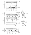
図2は、本発明の実施の形態1に係る無線通信モジュールを示す図である。点灯回路接続端子5は、図示しない商用電源と接続される点灯回路3と接続される。電源回路6は、点灯回路接続端子5を介して点灯回路3から供給される電源を無線通信制御回路7に供給する。アンテナ8は他の照明器具又は照明制御装置と信号を送受信する。無線通信制御回路7は、アンテナ8で受信した信号を点灯回路接続端子5を介して点灯回路3に送信する。なお、アンテナ8は、図2のように無線通信モジュール4内に配置してもよいし、外部に配置してもよい。
FIG. 2 is a diagram showing a wireless communication module according to the first embodiment of the present invention. The lighting
DIPスイッチ9はユーザ又は工事業者の操作によって指令を受け付ける指令受付手段である。無線通信制御回路7は、このDIPスイッチ9がON(SHORT)の場合にはL信号を検出し、DIPスイッチ9がOFF(OPEN)の場合にはH信号を検出する。無線通信モジュール4は、ユーザ又は工事業者の操作によって受け付けられたDIPスイッチ9によるこの2種類の信号を無線通信制御回路7で検出してアドレスを設定する。
The
図3は、本発明の実施の形態1に係る無線通信モジュールを示す斜視図である。無線通信モジュール4のケース10内に図2の各構成が収納される。ケース10の材質は、電波を遮閉しないPC+ABS等の樹脂が好ましい。DIPスイッチ9はユーザ又は工事業者が操作し易いようにケース10から露出して配置される。照明器具1に無線通信モジュール4を取り付けた状態でユーザ又は工事業者はアドレス設定のためにDIPスイッチ9を操作する。
FIG. 3 is a perspective view showing a wireless communication module according to the first embodiment of the present invention. Each configuration of FIG. 2 is housed in the
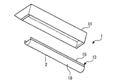
図4は、図1の照明器具から光源ユニットを外した状態を示す斜視図である。図5は、図4の器具本体と光源ユニットの4面図(a〜d)と、器具本体に光源ユニットを取り付ける工程を示す側面図(e)と、図1の照明器具の正面図(f)である。 FIG. 4 is a perspective view showing a state in which the light source unit is removed from the lighting fixture of FIG. 5A and 5B are a four-view view (a to d) of the fixture main body and the light source unit of FIG. 4, a side view (e) showing a process of attaching the light source unit to the fixture main body, and a front view (f) of the lighting fixture of FIG. ).
照明器具1は、天井に設置される器具本体11と、器具本体11に取り付けられる光源ユニット12とを備える。器具本体11には、コネクタ付きの電源端子台13と、2つの取付バネ14が取り付けられている。光源ユニット12は、取付板15と、この取付板15に取り付けられる電源16(点灯回路3)と、制御ユニット17(無線通信モジュール4)と、LEDモジュール2と、透光性を有するカバー18と、器具本体11の取付バネ14に引っ掛けられる受具19とを備える。制御ユニット17は、DIPスイッチ9を有しており、取付板15と対向する面側から操作可能な状態となっている。アンテナ8は制御ユニット17内に配置してもよいが、外部に配置してもよい。図5では制御ユニット17と電源16とを別々に構成して配線で接続する場合を例示したが、電源16内に制御ユニット17を配置して一体で構成してもよい。ただし、この場合もDIPスイッチ9は、アドレス設定しやすいように外部に露出させておく。
The lighting fixture 1 includes a fixture
次に、光源ユニット12を器具本体11へ固定する工程について説明する。まず、制御ユニット17のDIPスイッチ9を予め設定したいアドレスに対応するように操作を行う。取付バネ14が受具19に引っ掛けられると、光源ユニット12は器具本体11に仮取り付けされた状態となり、この状態で電源端子台13のコネクタと電源16のコネクタとを接続する。光源ユニット12を器具本体11に押し上げて、取付バネ14を受具19に本止めすることで光源ユニット12を器具本体11に固定する。
Next, a step of fixing the
次に、光源ユニット12を器具本体11へ取り付けた後に、アドレスを設定(変更)する場合について説明する。器具本体11に取り付けた光源ユニット12を引き下げ、光源ユニット12を仮取り付けの状態にし、器具本体11と光源ユニット12の間に空間ができるようにする。次に、この空間にユーザが手を入れ、DIPスイッチ9を操作しアドレスを設定(変更)する。このようにすることで、光源ユニット12を器具本体11から取り外すことなく、しかも電源端子台13のコネクタと電源16のコネクタを外すことなくアドレスを設定することができるので、アドレス設定の作業性が向上する。また、アドレスをDIPスイッチ9で設定するようにしているので、目視しなくても、DIPスイッチ9を触った感触で、DIPスイッチ9の位置を把握することができる。
Next, a case where the address is set (changed) after the
なお、設置場所によっては光源ユニット12を器具本体11から取り外してアドレス設定したい場合も、この取付バネ14と受具19の構成によれば容易に対応できる。また、取付バネ14と受具19を器具本体11、取付板15の長手方向両端に配置する場合を例示したが、取付け箇所、個数はこれに限らず適宜調整してもよい。例えば器具本体11、取付板15の略中央に一箇所配置して構成してもよい。
Depending on the installation location, even if the
図6は、本発明の実施の形態1に係る照明システムを示す図である。第1の照明システム20aは、照明制御装置21aと、照明制御装置21aと無線通信する複数の照明器具22aとを有する。第2の照明システム20bは、照明制御装置21bと、照明制御装置21bと無線通信する複数の照明器具22bとを有する。第1及び第2の照明システム20a,20bにおいて、ユーザがリモコン等により照明制御装置21a,21bに指令を送信すると、その指令に応じて照明制御装置21a,21bとそれぞれ関連付けられた複数の照明器具22a,22bが制御される。このように照明制御装置が複数台ある場合、照明器具22aは照明制御装置21aと無線通信するためのアドレス設定が必要であり、照明器具22bは照明制御装置21bと無線通信するためのアドレス設定が必要である。
FIG. 6 is a diagram showing a lighting system according to the first embodiment of the present invention. The
図6の照明システム構成を例としてアドレス設定の関連付けについて説明する。照明制御装置21aは、L信号のアドレスが設定された照明器具22aを制御するようリモコン等により設定される。照明器具22aは、図2に示す通りDIPスイッチ9によって定められたL信号を無線通信制御回路7が検出して、L信号のアドレスに設定される。以上より、照明器具22aと照明制御装置21aは、L信号のアドレスで関連付けられ、無線通信を行うことが可能となる。
The association of address settings will be described using the lighting system configuration of FIG. 6 as an example. The
一方、照明制御装置21bは、H信号のアドレスを設定した照明器具22bを制御するようリモコン等により設定される。照明器具22bは、DIPスイッチ9によって定められたH信号を無線通信制御回路7が検出して、H信号のアドレスに設定される。以上より、照明器具22bと照明制御装置21bは、H信号のアドレスで関連付けられ、無線通信を行うことが可能となる。従って、図6に示すように同一空間に複数台の照明制御装置21a,21bが設置されていても、本実施の形態の構成であれば、制御する照明器具22a,22bを容易に区別することができる。例えば、照明制御装置21aと照明制御装置21bが接近して配置されている場合でも、関連付けられた照明器具22a,22bを確実に制御することができる。しかも、照明器具22aと照明器具22bが同じエリア内で混在していても確実に制御できる。また、照明制御装置21aと照明制御装置21bは関連付けられた照明器具22a,22bに対して同時に通信制御するようにしてもよいし、照明制御装置21a,21bに対して予め優先順位付けの設定をしておき、その優先順位に基づいて照明器具22a,22bを順次制御するようにしてもよい。例えば照明制御装置21aの方を照明制御装置21bよりも優先度を高く設定するようにしてもよいし、逆にしてもよい。
On the other hand, the
以上説明したように、本実施の形態では、無線通信モジュール4のアドレスはDIPスイッチ9の操作に基づいて設定される。このため、ユーザ又は工事業者が無線通信用のアドレスを容易に設定することができる。また、DIPスイッチ9の極数を増やすことで、関連付けられる照明制御装置の台数やシステム構成を増やすことが可能であり、照明システム構成によって、アドレス設定の組み合わせを自由に決定することができる。例えば、8極のON/OFF操作が可能なスイッチを使用すると、256通りのアドレス設定が可能になる。
As described above, in the present embodiment, the address of the
実施の形態2.
図7は、本発明の実施の形態2に係る照明器具の器具本体と光源ユニットの4面図(a〜d)である。実施の形態1の図5では制御ユニット17(無線通信モジュール4)が光源ユニット12側にある場合について説明したが、図7のように器具本体11側にあっても構わない。この場合、アドレスの設定を行う際に光源ユニット12を器具本体11から取り外すことが好ましいが、複数の器具本体11を天井に設置した状態でそれぞれの器具本体11のアドレス設定を行うことができる。従って、隣り合う器具本体11のアドレスを同じにしたり、異なるものにしたりする時に、作業者が目視でアドレスを確認することができ、設定作業を効率的に行うことができる。なお、実施の形態2も設置場所によっては実施の形態1のように光源ユニット12を器具本体11に仮取付けした状態で手を差し入れてアドレス設定してもよい。
FIG. 7 is a four-view view (a to d) of the fixture main body and the light source unit of the lighting fixture according to the second embodiment of the present invention. Although the case where the control unit 17 (wireless communication module 4) is on the
実施の形態3.
図8は、本発明の実施の形態3に係る照明器具を示す斜視図である。図9は、図8の照明器具から光源ユニットを外した状態を示す斜視図である。図10は、図9の器具本体と光源ユニットの4面図(a〜d)と、図8の照明器具の側面図(e)と、図8の照明器具の正面図(f)である。本実施の形態では、実施の形態1と比べて制御ユニット17(無線通信モジュール4)の取り付け位置が変更されている。
FIG. 8 is a perspective view showing a lighting fixture according to a third embodiment of the present invention. FIG. 9 is a perspective view showing a state in which the light source unit is removed from the lighting fixture of FIG. 10 is a four-view view (a to d) of the fixture main body and the light source unit of FIG. 9, a side view (e) of the lighting fixture of FIG. 8, and a front view (f) of the lighting fixture of FIG. In the present embodiment, the mounting position of the control unit 17 (wireless communication module 4) is changed as compared with the first embodiment.
制御ユニット17は、取付板15から側面方向に突出する突出板にねじ止めや接着等により取り付けられ、カバー18の側面に並列に配置している。この制御ユニット17には、カバー18と対向する外郭側から操作可能な位置にDIPスイッチ9が取り付けられている。そのため、実施の形態1に係る照明器具1とは異なり、光源ユニット12を器具本体11に取り付けた状態でアドレス設定ができ、また、作業者が目視でDIPスイッチ9の状態(アドレス設定情報)を確認することができる。
The
なお、実施の形態3では、制御ユニット17を全て外部に配置する場合を例示したが、DIPスイッチ9は外部に露出させた状態で一部を器具本体11内に埋め込むように配置してもよく、この場合、光源ユニット12の照明効率の点で好ましい。また、器具本体11の天井設置面に対して略垂直となるよう配置したが、照射方向に行くに従って外方に向くように配置してもよく、同様に照射効率の点で好ましい。この場合も、制御ユニット17の一部を器具本体11内に埋め込んでもよい。また、制御ユニット17を取付板15の周囲の長手方向片側の略中央に配置した例を示したが、設置場所の状況に応じて配置すればよく、長手方向端側に配置してもよいし、短手方向片側に配置してもよい。
In the third embodiment, the case where all the
実施の形態4.
図11は、本発明の実施の形態4に係る照明器具の器具本体と光源ユニットの4面図(a〜d)と、器具本体に光源ユニットを取り付ける工程を示す側面図(e)である。本実施の形態ではDIPスイッチ9が制御ユニット17(無線通信モジュール4)の天井面側に配置されている点が実施の形態3と異なる。これにより、アドレス設定を行う場合、実施の形態1と同様に、光源ユニット12を器具本体11から引き下げて仮取り付け状態にすることが好ましい。ただし、DIPスイッチ9がユーザに直接目視されないため、照明器具1の意匠性を向上させることができる。なお、実施の形態4も、設置場所によっては光源ユニット12を器具本体11から取り外して対応するようにしてもよい。また、制御ユニット17の配置方法も、DIPスイッチ9が天井面側に配置されていればよいので、実施の形態3のように設置場所の状況に応じて配置可能である。
FIG. 11 is a four-view view (a to d) of the fixture main body and the light source unit of the lighting fixture according to the fourth embodiment of the present invention, and a side view (e) showing a step of attaching the light source unit to the fixture main body. The present embodiment is different from the third embodiment in that the
実施の形態5.
図12は、本発明の実施の形態5に係る無線通信モジュールを示す図である。実施の形態1〜4のDIPスイッチ9の代わりに、外部から指令を受け付ける指令受付手段として、アドレス設定のための光信号を受信する受光素子23が設けられている。無線通信モジュール4のアドレスは受光素子23にて受信した光信号に基づいて設定される。ユーザ又は工事業者は、リモコン等で無線通信モジュール4の受光素子23に所定のアドレスを送信することで、各々の照明器具に対してアドレスを容易に設定することができる。具体的には、無線通信モジュール4のアドレスは、受光素子23にて受信した光信号により、無線通信制御回路7が保存している固有アドレスを抽出して設定される。
FIG. 12 is a diagram showing a wireless communication module according to the fifth embodiment of the present invention. Instead of the
図13は、本発明の実施の形態5に係る無線通信モジュールを示す斜視図である。無線通信モジュール4のケース10内に図12の各構成が収納される。ケース10の材質は、電波を遮閉しないPC+ABS等の樹脂が好ましい。受光素子23は、外部リモコン等からの光信号を受信し易いようケース10から露出するように配置される。
FIG. 13 is a perspective view showing the wireless communication module according to the fifth embodiment of the present invention. Each configuration of FIG. 12 is housed in the
図14は、本発明の実施の形態5に係る照明器具を示す斜視図である。無線通信モジュール4の受光素子23が照明器具1の外郭から露出している。リモコン24から受光素子23に光信号を送信することで、照明器具1のアドレスを設定することができる。なお、LEDモジュール2のカバー18から受光素子23を露出させる場合を例示したが、照明器具1であればどこに配置してもよく、例えば器具本体11側に配置して器具本体11から露出させるよう構成してもよい。
FIG. 14 is a perspective view showing a lighting fixture according to a fifth embodiment of the present invention. The
図15は、図14の照明器具の4面図(a〜d)と光源ユニットからカバーを取り外した状態を示す図(e)である。受光部25が取付板15に設けられている。この受光部25を介してリモコン24からの光が受光素子23に入力される。この受光部25は光を透過させる構造であればよく、例えば受光部25のカバー18部分はそのまま残しても構わない。また、受光部25のカバー18部分を取り除いて穴構造にし、その中に受光素子23を埋め込むようにしてもよい。また、受光部25内に光信号を増強するような光透過部材を充填する構成にしてもよい。
15 is a four-view view (a to d) of the lighting fixture of FIG. 14, and FIG. 15 is a view (e) showing a state in which the cover is removed from the light source unit. The
図6の照明システム構成を例としてアドレス設定の関連付けについて説明する。照明制御装置21aは、リモコン24からの光信号に基づいて、照明制御装置21a自体のアドレスと、照明制御装置21aと複数の照明器具22aから構成される第1の照明システム20aのアドレスを設定する。照明器具22aには、リモコン24からの光信号に基づいて、制御される照明制御装置21aのアドレスとシステムのアドレスを設定する。以上より、照明器具22aと照明制御装置21aはアドレスで関連付けられ、無線通信を行うことが可能となる。
The association of address settings will be described using the lighting system configuration of FIG. 6 as an example. The
照明制御装置21bは、リモコン24からの光信号に基づいて、照明制御装置21b自体のアドレスと、照明制御装置21bと複数の照明器具22bから構成される第2の照明システム20bのアドレスを設定する。照明器具22bには、リモコン24からの光信号に基づいて、制御される照明制御装置21bのアドレスとシステムのアドレスを設定する。以上より、照明器具22bと照明制御装置21bはアドレスで関連付けられ、無線通信を行うことが可能となる。
The
従って、図6に示すように同一空間に複数台の照明制御装置が設置されていても、本実施の形態の構成であれば、制御する照明器具を容易に区別することができる。また、照明器具22aの1台を個別に制御する場合は、対象の照明器具22aからリモコン24で直接抽出した固有のアドレスを照明制御装置21aにインプットすることで、照明制御装置21aと照明器具22aの1台が関連付けられ、インプットされた照明器具22aのみ制御することが可能になる。
Therefore, even if a plurality of lighting control devices are installed in the same space as shown in FIG. 6, the lighting fixtures to be controlled can be easily distinguished by the configuration of the present embodiment. When controlling one of the
以上説明したように、本実施の形態では、無線通信モジュール4のアドレスは受光素子23が受信した光信号に基づいて設定される。このため、ユーザ又は工事業者が無線通信用のアドレスを容易に設定することができる。また、照明システムを設定した後に照明制御装置と照明器具の組み合わせを変更したい場合、リモコン等で容易に組み合わせを変更することができる。
As described above, in the present embodiment, the address of the
実施の形態6.
図16は、本発明の実施の形態6に係る照明器具を示す斜視図である。実施の形態5の図14と比較すると、無線通信モジュール4の配置のみ異なり、その他の構成及び動作は同一である。無線通信モジュール4は、LEDモジュール2の開口部から受光素子23の一部分が露出するように、LEDモジュール2を覆うカバー18の内部に配置されている。リモコン24からの光信号は、カバー18を透過して、無線通信モジュール4の受光素子23に送信される。無線通信モジュール4をカバー18の内部に配置することにより、受光素子23や無線通信モジュール4の電子部品等に直接触れる可能性がなく、安全性に優れている。また、外観が他の照明器具と変わることなく、照明器具の統一性が図れる。
FIG. 16 is a perspective view showing a lighting fixture according to a sixth embodiment of the present invention. Compared with FIG. 14 of the fifth embodiment, only the arrangement of the
1 照明器具、2 LEDモジュール(光源)、3 点灯回路、4 無線通信モジュール、7 無線通信制御回路、8 アンテナ、9 DIPスイッチ(指令受付手段)、11 器具本体、12 光源ユニット、18 カバー、21a,21b 照明制御装置、23 受光素子(指令受付手段) 1 Lighting fixture, 2 LED module (light source), 3 lighting circuit, 4 wireless communication module, 7 wireless communication control circuit, 8 antenna, 9 DIP switch (command receiving means), 11 fixture body, 12 light source unit, 18 cover, 21a , 21b Lighting control device, 23 Light receiving element (command receiving means)
Claims (1)
光源と、
前記光源が取り付けられた取付板と、
前記取付板の下面側に設けられ、透光性を有するカバーと、
前記光源を点灯制御する点灯回路と、
前記点灯回路に接続され、他の照明器具又は照明制御装置と無線通信を行う無線通信モジュールとを備え、
前記無線通信モジュールは、
受信した信号を前記点灯回路に送信する無線通信制御回路と、
外部から指令を受け付ける指令受付手段とを有し、
前記指令受付手段は、操作を受け付けるスイッチであり、
前記無線通信モジュールのアドレスは、前記スイッチの操作に基づいて設定され、
前記無線通信モジュールは、前記取付板の上面側に設けられ、前記器具本体と前記取付板とに挟まれた空間に配置されていることを特徴とする光源ユニット。 In the light source unit attached to the fixture body
Light source and
The mounting plate to which the light source is mounted and
A cover provided on the lower surface side of the mounting plate and having translucency,
A lighting circuit that controls the lighting of the light source and
It is provided with a wireless communication module that is connected to the lighting circuit and performs wireless communication with other lighting equipment or a lighting control device.
The wireless communication module
A wireless communication control circuit that transmits the received signal to the lighting circuit, and
It has a command receiving means that accepts commands from the outside,
The command receiving means is a switch that receives an operation.
The address of the wireless communication module is set based on the operation of the switch.
The wireless communication module is a light source unit provided on the upper surface side of the mounting plate and arranged in a space sandwiched between the appliance main body and the mounting plate .
Priority Applications (2)
| Application Number | Priority Date | Filing Date | Title |
|---|---|---|---|
| JP2019041679A JP6798570B2 (en) | 2019-03-07 | 2019-03-07 | Light source unit |
| JP2020191049A JP7404216B2 (en) | 2019-03-07 | 2020-11-17 | lighting equipment |
Applications Claiming Priority (1)
| Application Number | Priority Date | Filing Date | Title |
|---|---|---|---|
| JP2019041679A JP6798570B2 (en) | 2019-03-07 | 2019-03-07 | Light source unit |
Related Parent Applications (1)
| Application Number | Title | Priority Date | Filing Date |
|---|---|---|---|
| JP2015069510A Division JP6500559B2 (en) | 2015-03-30 | 2015-03-30 | Lighting equipment and lighting system |
Related Child Applications (1)
| Application Number | Title | Priority Date | Filing Date |
|---|---|---|---|
| JP2020191049A Division JP7404216B2 (en) | 2019-03-07 | 2020-11-17 | lighting equipment |
Publications (2)
| Publication Number | Publication Date |
|---|---|
| JP2019083216A JP2019083216A (en) | 2019-05-30 |
| JP6798570B2 true JP6798570B2 (en) | 2020-12-09 |
Family
ID=66671212
Family Applications (1)
| Application Number | Title | Priority Date | Filing Date |
|---|---|---|---|
| JP2019041679A Active JP6798570B2 (en) | 2019-03-07 | 2019-03-07 | Light source unit |
Country Status (1)
| Country | Link |
|---|---|
| JP (1) | JP6798570B2 (en) |
Families Citing this family (1)
| Publication number | Priority date | Publication date | Assignee | Title |
|---|---|---|---|---|
| JP7734350B2 (en) * | 2021-12-22 | 2025-09-05 | パナソニックIpマネジメント株式会社 | Lighting control system and slave |
-
2019
- 2019-03-07 JP JP2019041679A patent/JP6798570B2/en active Active
Also Published As
| Publication number | Publication date |
|---|---|
| JP2019083216A (en) | 2019-05-30 |
Similar Documents
| Publication | Publication Date | Title |
|---|---|---|
| EP3261411B1 (en) | Driver system for a light emitting device | |
| US8436552B2 (en) | Power source control device of illuminator and lighting system | |
| US20120215325A1 (en) | Lamp device | |
| CA2523313C (en) | Ac powered wireless control 3-way light switch transmitter | |
| US6650029B1 (en) | Remotely controllable electrical switching apparatus | |
| AU782063B2 (en) | An operating theater lamp | |
| CN111052871B (en) | Intelligent decorative part for embedded lighting fixture | |
| JP6500559B2 (en) | Lighting equipment and lighting system | |
| US10568181B2 (en) | Surgical light and method for operating a surgical light | |
| US20130049633A1 (en) | Illumination system relating to light-emitting-diode lamps | |
| US8598993B2 (en) | Method for wiring devices in a structure using a wireless network | |
| JP7497048B2 (en) | Remote control device for lighting fixtures and lighting fixtures | |
| JP6798570B2 (en) | Light source unit | |
| JP5234343B2 (en) | Monitoring terminal for remote control and lighting control system | |
| JP2008052945A (en) | Remote control receiver for lighting equipment | |
| JP7404216B2 (en) | lighting equipment | |
| JP2014120789A (en) | Switch system and wall fitting switch used for the same | |
| JP6886845B2 (en) | Signal module and lighting equipment | |
| JP2017059499A (en) | Lighting device and lighting fixture | |
| KR101956724B1 (en) | Apparatus for controlling dimming of led lighting device | |
| CN102156458A (en) | Control and protection apparatus for electric facility | |
| KR20130119602A (en) | Led lighting controller | |
| JP2019204665A (en) | Sensor unit, illuminating fixture, and electronic equipment | |
| KR20120077662A (en) | Remote control system for lighting instruments of house | |
| KR101738261B1 (en) | LED lighting system for control color temperature and dimming |
Legal Events
| Date | Code | Title | Description |
|---|---|---|---|
| A621 | Written request for application examination |
Free format text: JAPANESE INTERMEDIATE CODE: A621 Effective date: 20190307 |
|
| A977 | Report on retrieval |
Free format text: JAPANESE INTERMEDIATE CODE: A971007 Effective date: 20191211 |
|
| A131 | Notification of reasons for refusal |
Free format text: JAPANESE INTERMEDIATE CODE: A131 Effective date: 20200114 |
|
| A131 | Notification of reasons for refusal |
Free format text: JAPANESE INTERMEDIATE CODE: A131 Effective date: 20200602 |
|
| A521 | Request for written amendment filed |
Free format text: JAPANESE INTERMEDIATE CODE: A523 Effective date: 20200716 |
|
| TRDD | Decision of grant or rejection written | ||
| A01 | Written decision to grant a patent or to grant a registration (utility model) |
Free format text: JAPANESE INTERMEDIATE CODE: A01 Effective date: 20201020 |
|
| A61 | First payment of annual fees (during grant procedure) |
Free format text: JAPANESE INTERMEDIATE CODE: A61 Effective date: 20201102 |
|
| R150 | Certificate of patent or registration of utility model |
Ref document number: 6798570 Country of ref document: JP Free format text: JAPANESE INTERMEDIATE CODE: R150 |
|
| R250 | Receipt of annual fees |
Free format text: JAPANESE INTERMEDIATE CODE: R250 |
|
| R250 | Receipt of annual fees |
Free format text: JAPANESE INTERMEDIATE CODE: R250 |
|
| R250 | Receipt of annual fees |
Free format text: JAPANESE INTERMEDIATE CODE: R250 |