JP6796331B2 - Baffle type speaker and its assembly set - Google Patents
Baffle type speaker and its assembly set Download PDFInfo
- Publication number
- JP6796331B2 JP6796331B2 JP2017247500A JP2017247500A JP6796331B2 JP 6796331 B2 JP6796331 B2 JP 6796331B2 JP 2017247500 A JP2017247500 A JP 2017247500A JP 2017247500 A JP2017247500 A JP 2017247500A JP 6796331 B2 JP6796331 B2 JP 6796331B2
- Authority
- JP
- Japan
- Prior art keywords
- speaker unit
- baffle plate
- speaker
- vibration
- vibrating
- Prior art date
- Legal status (The legal status is an assumption and is not a legal conclusion. Google has not performed a legal analysis and makes no representation as to the accuracy of the status listed.)
- Active
Links
- 239000000123 paper Substances 0.000 description 10
- 239000000463 material Substances 0.000 description 8
- 230000000694 effects Effects 0.000 description 5
- 239000004744 fabric Substances 0.000 description 4
- 230000005540 biological transmission Effects 0.000 description 2
- 230000004048 modification Effects 0.000 description 2
- 238000012986 modification Methods 0.000 description 2
- 239000011347 resin Substances 0.000 description 2
- 229920005989 resin Polymers 0.000 description 2
- 239000013589 supplement Substances 0.000 description 2
- 238000005452 bending Methods 0.000 description 1
- 238000010586 diagram Methods 0.000 description 1
- 238000009434 installation Methods 0.000 description 1
- 230000002452 interceptive effect Effects 0.000 description 1
- 238000000034 method Methods 0.000 description 1
- 238000000465 moulding Methods 0.000 description 1
Images


Description
本発明は、バッフル型スピーカに関する。 The present invention relates to a baffle type speaker.
スピーカには、スピーカユニットをエンクロージャで囲った密閉型のものがある。こうした密閉型のスピーカは、内部に封じられた空気が妨げとなり、コーン紙に背圧がかかってコーン紙の動作が抑制されてしまうことが知られている。一方、平面バッフル型は、バッフル板のみで密閉されていないため密閉型のような問題は生じない。このバッフル板は、スピーカユニットの後側から出る音が前側に回り込むことを防ぐために用いられるが、このバッフル板そのものを振動させ、音の発生源として用いる技術が提案されている(例えば、特許文献1)。 Some speakers are sealed types in which the speaker unit is surrounded by an enclosure. It is known that such a closed type speaker is hindered by the air sealed inside, and back pressure is applied to the cone paper to suppress the operation of the cone paper. On the other hand, the flat baffle type does not have the same problem as the closed type because it is not sealed only by the baffle plate. This baffle plate is used to prevent the sound emitted from the rear side of the speaker unit from wrapping around to the front side, and a technique has been proposed in which the baffle plate itself is vibrated and used as a sound source (for example, Patent Documents). 1).
特許文献1のスピーカでは、バッフル板を音の発生源として利用することができる。しかし、例えばバッフル板の大きさや向きによっては後側から出る音が前側に回り込むことを十分に防止することができなくなる。すなわち、バッフル板としての役割を果たすようにした場合、その大きさ、形状、向きが制約を受けることになる。さらに、これらの制約を受けることによって、バッフル板を利用して生じさせた音についても、周波数や指向性が制約を受けることになる。 In the speaker of Patent Document 1, the baffle plate can be used as a sound source. However, for example, depending on the size and orientation of the baffle plate, it is not possible to sufficiently prevent the sound emitted from the rear side from wrapping around to the front side. That is, when the baffle plate is made to play a role, its size, shape, and orientation are restricted. Further, due to these restrictions, the frequency and directivity of the sound generated by using the baffle plate are also restricted.
本発明は上記事情に鑑み、バッフル板を音の発生源として利用しつつも、全体としてバッフル板に対する制約の影響を抑えたバッフル型スピーカを提供することを目的とする。 In view of the above circumstances, an object of the present invention is to provide a baffle type speaker that uses a baffle plate as a sound source and suppresses the influence of restrictions on the baffle plate as a whole.
上記目的を解決する本発明のバッフル型スピーカは、
スピーカユニットと、
前記スピーカユニットが取り付けられ、該スピーカユニットの振動に追従して振動するバッフル板と、
前記バッフル板とは別部材であって、前記スピーカユニットの振動に追従して振動する振動部材と、を備え、
前記振動部材が、前記スピーカユニットに離間自在に接し、且つ、前記スピーカユニットと接しない位置で固定されたものであることを特徴とする。
The baffle type speaker of the present invention that solves the above object is
With the speaker unit
A baffle plate to which the speaker unit is attached and vibrates following the vibration of the speaker unit,
It is provided with a vibrating member which is a member separate from the baffle plate and vibrates following the vibration of the speaker unit .
The vibrating member is characterized in that it is in contact with the speaker unit so as to be separable and is fixed at a position not in contact with the speaker unit .
このバッフル型スピーカによれば、振動部材を用いて、バッフル板とは異なる周波数特性を持たせたり、音の方向を広げたりすることができる。 According to this baffle type speaker, it is possible to give a frequency characteristic different from that of the baffle plate or widen the direction of sound by using the vibrating member.
このバッフル型スピーカによれば、スピーカユニットから振動部材に伝わる振動を適切に調整することができる。 According to this baffle type speaker, the vibration transmitted from the speaker unit to the vibrating member can be appropriately adjusted.
また、このバッフル型スピーカは、
前記スピーカユニットにおける、前記振動部材が接する位置は、該スピーカユニットにおける、前記バッフル板への取り付け位置とは異なっていてもよい。
In addition, this baffle type speaker is
The position of the speaker unit in contact with the vibrating member may be different from the position of the speaker unit attached to the baffle plate.
このバッフル型スピーカによれば、バッフル板と振動部材が干渉しないようにすることができる。 According to this baffle type speaker, it is possible to prevent the baffle plate and the vibrating member from interfering with each other.
また、このバッフル型スピーカは、
前記振動部材が、
前記スピーカユニットの後部と接するものであってもよい。
In addition, this baffle type speaker is
The vibrating member
It may be in contact with the rear part of the speaker unit.
このバッフル型スピーカによれば、スピーカユニットの振動の発生源である磁石とボイスコイルからの振動を効率よく振動部材に伝えることができる。 According to this baffle type speaker, the vibration from the magnet and the voice coil, which are the sources of vibration of the speaker unit, can be efficiently transmitted to the vibrating member.
また、このバッフル型スピーカは、
前記振動部材と前記スピーカユニットとの間にかかる接触圧力を調整可能な調整部材を備えたものであってもよい。
In addition, this baffle type speaker is
It may be provided with an adjusting member capable of adjusting the contact pressure applied between the vibrating member and the speaker unit.
このバッフル型スピーカによれば、振動部材への振動の伝達具合を調整することができる。 According to this baffle type speaker, the degree of transmission of vibration to the vibrating member can be adjusted.
また、上記いずれかのバッフル型スピーカについて、組立セットとしてもよい。 Further, any of the above baffle type speakers may be assembled as an assembly set.
本発明によれば、バッフル板を音の発生源として利用しつつも、全体としてバッフル板に対する制約の影響を抑えたバッフル型スピーカを提供することができる。 According to the present invention, it is possible to provide a baffle type speaker that uses the baffle plate as a sound source and suppresses the influence of restrictions on the baffle plate as a whole.
以下、図面を用いて、本発明のバッフル型スピーカの実施形態について説明する。 Hereinafter, embodiments of the baffle type speaker of the present invention will be described with reference to the drawings.
[第一実施形態]
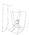
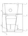
以下、図1〜図5を用いて、第一実施形態のバッフル型スピーカの構成について説明する。図1は、第一実施形態のバッフル型スピーカを示す斜視図である。図2は、図1に示すバッフル型スピーカの背面斜視図である。図3は、図2に示すバッフル型スピーカから振動部材を外した状態を示す背面斜視図である。図4は、組立前の振動バッフル板、振動部材、張力付与部材を示す図である。図5は、スピーカユニットの断面図である。
[First Embodiment]
Hereinafter, the configuration of the baffle type speaker of the first embodiment will be described with reference to FIGS. 1 to 5. FIG. 1 is a perspective view showing a baffle type speaker of the first embodiment. FIG. 2 is a rear perspective view of the baffle type speaker shown in FIG. FIG. 3 is a rear perspective view showing a state in which the vibrating member is removed from the baffle type speaker shown in FIG. FIG. 4 is a diagram showing a vibration baffle plate, a vibration member, and a tension applying member before assembly. FIG. 5 is a cross-sectional view of the speaker unit.
図1〜図3に示す第一実施形態のバッフル型スピーカ1は、スピーカユニット10と、このスピーカユニット10が設けられた振動バッフル板11と、振動バッフル板11の背面に配置され、スピーカユニット10の後部に接する振動部材12とを備えたものである。また、振動バッフル板11の背面側には、張力付与部材13が設けられている。これらの、振動バッフル板11、振動部材12、張力付与部材13は、元は厚さ1mm程度の1枚の厚紙から切り離されたものである。図4には、振動バッフル板11、振動部材12、張力付与部材13が1枚の紙の状態であったことが示されている。なお、図4では、振動バッフル板11、振動部材12、張力付与部材13の他に、左下に余ったパーツ14があることが示されているが、このパーツ14を交換用の振動部材として用いるようにしてもよい。その場合、これらの振動部材の周波数特性を異ならせておき、求められる周波数特性にあったものを使い分けることができるようにしてもよい。
The baffle type speaker 1 of the first embodiment shown in FIGS. 1 to 3 is arranged on the back surface of the
スピーカユニット10は、図5に示すように、後部に磁石100とボイスコイル101を設け、ボイスコイル101を励磁することによって振動を生じさせ、この振動によって前部に設けられたコーン紙102を振動させて音を発生させるものである。
As shown in FIG. 5, the
振動バッフル板11は、図4に示すように1枚の厚紙を折り曲げて構成されたものである。なお、折り曲げる際には、折り線A1、A2を除いた他の折り線を同じ方向に曲げることで、図1に示す形に組み立てることができる。このとき図4において符号Sを付した面(以下、面S)がバッフル板として機能する部分であり、この面Sにスピーカユニット10を固定するための孔が形成されている。また図4において上記面Sの左右の領域は、図1においては張力付与部材13によって固定されているが、このとき背面側に撓んだ振動バッフル板11に対して張力が付与された状態が維持されるようになっている。また、図4において面Sよりも下の領域は、折り曲げられて振動バッフル板11の土台部分となる。
As shown in FIG. 4, the vibrating
振動バッフル板11に固定されたスピーカユニット10が振動すると、振動バッフル板11もこれに伴って振動する。すなわち、振動バッフル板11は、スピーカユニット10の振動に追従して振動するバッフル板である。振動バッフル板11の面Sは、張力付与部材13によって張力が付与された状態となっているが、この張力は面Sの上方向にいくほど低くなっている。この構成によって、全体として張力が一律にならずに分散するため、振動バッフル板11の共振周波数に偏りが生じないように構成されている。
When the
振動部材12は、直立した状態で振動バッフル板11の土台部分のスリットに固定されている。この振動部材12は、スピーカユニット10とは固定されておらず、スピーカユニット10の後部に離間自在に接した状態となっている。また、振動バッフル板11およびスピーカユニット10は、その自重によって振動部材12に寄り掛かった状態(接触圧力が生じた状態)となっている。さらに、不図示のテグスによっても、スピーカユニット10と振動部材12との間に接触圧力を生じさせる構成を採用している。スピーカユニット10と振動部材12との間の接触圧力が生じていることにより、スピーカユニット10の振動が振動部材12に伝わり、振動部材12がスピーカユニット10の振動に追従して振動するように構成されている。なお、このテグスについては、その締め付け具合を調整することでスピーカユニット10と振動部材12との間の接触圧力を調整することが可能となっている。なお、振動部材12とスピーカユニット10との接する範囲については、点接触であっても線接触であってもよく、振動が伝わるものであれば特に限定されるものではない。
The vibrating
以下、上記第一実施形態のバッフル型スピーカ1の効果について説明する。 Hereinafter, the effect of the baffle type speaker 1 of the first embodiment will be described.
第一実施形態のバッフル型スピーカ1は、従来の平面バッフル型スピーカと同様の効果を有するものである。すなわち、スピーカユニット10が密閉されていないため、密閉型のようにコーン紙102の動作が抑制されることがなく、また振動バッフル板11を設けたことによって、後側から出る音が前側に回り込んで音が打ち消しあってしまうことを防止することができる。さらに、第一実施形態のバッフル型スピーカ1では、スピーカユニット10の磁石100とボイスコイル101によって生じる振動を利用して振動バッフル板11を振動させることにより、スピーカユニット10のコーン紙102だけでなく、振動バッフル板11も音の発生源(例えば、スピーカにおけるコーン紙に相当)として利用することができる。
The baffle type speaker 1 of the first embodiment has the same effect as the conventional flat baffle type speaker. That is, since the
上記説明したように第一実施形態のバッフル型スピーカ1において、振動バッフル板11は、後側から出る音が前側に回り込むことを防止するバッフル板としての機能に加え、スピーカユニット10と連動して音を発生させるスピーカとしての機能を有する。ここで、スピーカとしての機能だけに着目すると、求められる周波数特性や指向性に応じて、振動バッフル板11の大きさ、形状、向きを変更することが考えられる。しかし、バッフル板としての機能は、振動バッフル板11の大きさ、形状、向きによってその効果が低下する場合があり、求められる周波数特性や指向性によっては対応できない場合がある。
As described above, in the baffle type speaker 1 of the first embodiment, the
上記説明した第一実施形態のバッフル型スピーカ1では、スピーカユニット10の振動に追従して振動する振動部材12が設けられている。すなわち、振動バッフル板11の他にスピーカとしての機能を有する構成として、振動部材12を設けたものとなっている。また、振動バッフル板11はバッフル板として機能するための制約を受けるが、この振動部材12はこうした制約を受けない。このため、振動部材12には、様々な形態のものを採用することができる。
In the baffle type speaker 1 of the first embodiment described above, a
上記の振動部材12によれば、例えば振動バッフル板11において特定の音域でスピーカとしての機能が低下する場合であっても、振動部材12を用いてこの音域の音を補うことができる。例えば、振動部材12に低音特性の高い素材を用いることで、バッフル型スピーカ1の低音特性を向上させることができる。また、振動バッフル板11の向きはスピーカユニット10の向きによって決まるため、振動バッフル板11から生じる音の方向は制約を受けるが、振動部材12ではこうした制約がない。このため、振動バッフル板11によって生じる音の方向とは無関係に、様々な方向へ音を発生させて音に広がりを持たせることができる。以上のように、振動バッフル板11と振動部材12との組み合わせによって、一つのスピーカユニットで様々な音響効果を奏することができる。
According to the above-mentioned vibrating
以下、上記説明した第一実施形態のバッフル型スピーカ1についてその他採用し得る形態について説明する。 Hereinafter, other modes that can be adopted for the baffle type speaker 1 of the first embodiment described above will be described.
第一実施形態では、スピーカユニット10に追従して振動する振動バッフル板11として、厚紙を用いた構成について説明したが、これについては、スピーカユニット10に追従して振動し、音を発生させることができればよく、例えば、樹脂、紙、布、等、素材が限定されるものではない。ただし、スピーカユニット10のサイズが大きくなると、これに伴って増加する重量を支えるため、振動バッフル板11の剛性を高める必要が生じる。その結果、振動バッフル板11がスピーカユニット10に追従して振動しにくくなってしまうことから、上記のスピーカユニット10としては比較的小さいもの(例えば、直径が5cm〜10cm程度)が好ましい。
In the first embodiment, a configuration using thick paper as the vibrating
また、第一実施形態の振動バッフル板11では、張力付与部材13を用いて振動バッフル板11の共振周波数に偏りが生じないように構成されているが、スピーカユニット10の振動に追従して振動するバッフル板であれば、例えば後述する第二実施形態のように張力付与部材13を設けない構成であってもよい。
Further, the
また、振動部材12についても、第一実施形態のような板状のものに限らず、例えば、音叉のような棒状のものや、弦を張った構成のように、スピーカユニット10に追従して振動し、音を発生させることができるものであれば、その形状や素材が限定されるものではない。
Further, the vibrating
第一実施形態では、スピーカユニット10および振動バッフル板11の自重および不図示のテグスを利用してスピーカユニット10と振動部材12との間に接触圧力が生じる構成を採用している。すなわち、スピーカユニット10と振動部材12とは固定されておらず、これらが離間自在に接する構成となっている。この構成では、スピーカユニット10から振動部材12に対する接触圧力により、スピーカユニット10の振動を無理なく振動部材12に伝え、スピーカユニット10に追従して音を発生させることができる。なお、第一実施形態では振動部材12を振動バッフル板11のスリットに固定しているが、この固定位置についてはスピーカユニット10とは接しない位置であれば特に限定されるものではない。
In the first embodiment, a configuration is adopted in which a contact pressure is generated between the
なお、上記第一実施形態のように振動部材12がスピーカユニット10に離間自在に接する構成となっている場合には、スピーカユニット10に対して振動部材12を容易に着脱可能な構成にすることができるため、設置環境や再生する音の性質に応じて適切な振動部材12を選択して取り付けることができるようにしてもよい。
When the vibrating
上記第一実施形態では、スピーカユニット10と振動部材12が離間自在に接する構成を採用しているが、例えば、振動部材12をスピーカユニット10の後部に取り付け、スピーカユニット10が振動部材12を支持するようにした場合にも、スピーカユニット10の振動に追従して振動する振動部材12を設けた構成とすることができる。ただしこの構成を採用した場合、振動部材12の重さがスピーカユニット10を介して振動バッフル板11にかかり、振動バッフル板11の振動を妨げる可能性がある。このため、第一実施形態のようにスピーカユニット10と振動部材12が離間自在に接した構成とすることが好ましい。
In the first embodiment, the
また、第一実施形態では、スピーカユニット10が振動バッフル板11に取り付けられた位置と、スピーカユニット10と振動部材12が接する位置とが異なっている。これらの位置を共通にしてもよいが、振動バッフル板11と振動部材12のそれぞれの振動が干渉する可能性があるため、これらの位置を異ならせた構成とすることが好ましい。
Further, in the first embodiment, the position where the
また、第一実施形態では、振動部材12がスピーカユニット10の後部と接する構成となっている。この接する位置については例えばスピーカユニット10の側面であってもよく、スピーカユニット10の後部に限られるものではない。なお、図5に示すように、後部には振動の発生源となる磁石100とボイスコイル101が設けられていることから、振動部材12をスピーカユニット10の後部に接する構成とすることで、振動の発生源の近くに振動部材12を設けて効率よく振動させることができる。なお、この場合、スピーカユニット10の後部の形状に、これと接する部分の振動部材12の形状を合わせて接触面積を増加させることで、より効率よく振動を伝えることができる。
Further, in the first embodiment, the vibrating
第一実施形態では、スピーカユニット10および振動バッフル板11の自重や不図示のテグスを利用して振動部材12への接触圧力を生じさせる構成となっているが、接触圧力を生じさせる構成はこれに限定されるものではない。例えば、スピーカユニット10および振動バッフル板11の自重のみを利用する構成であってもよいし、自重を利用せずにテグスのみを利用する構成であってもよい。なお、第一実施形態のテグスについては、この構成に限定されるものではなく、スピーカユニット10と振動部材12の接触圧力を調整可能な調整部材を設けた構成であればよい。このような調整部材を設けた場合には、振動部材12への振動の伝達具合を調整することができる。
In the first embodiment, the
上記第一実施形態のバッフル型スピーカ1では、振動バッフル板11に張力付与部材13を設けて全体として張力が一律にならない構成を採用している。この構成については、振動バッフル板11に限らず、第一実施形態の振動部材12や、後述する第二実施形態の振動部材32に適用してもよい。すなわちこれらの振動部材が、平板状の部分を有するものであって、その平面における複数の方向に対して異なる大きさの張力を付与する張力付与部材を有するように構成してもよい。これにより、振動部材についても共振周波数に偏りが生じないように構成し、より音響効果を高めることができる。
In the baffle type speaker 1 of the first embodiment, the
[第二実施形態]
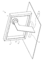
以下、図6、図7を用いて、第二実施形態のバッフル型スピーカの構成について説明する。図6は、第二実施形態のバッフル型スピーカを示す斜視図である。図7は、図6に示すバッフル型スピーカの背面斜視図である。
[Second Embodiment]
Hereinafter, the configuration of the baffle type speaker of the second embodiment will be described with reference to FIGS. 6 and 7. FIG. 6 is a perspective view showing the baffle type speaker of the second embodiment. FIG. 7 is a rear perspective view of the baffle type speaker shown in FIG.
図6、図7に示す第二実施形態のバッフル型スピーカ3は、スピーカユニット10と、このスピーカユニット10が設けられた振動バッフル板31と、振動部材32とを備えたものである。このうち振動部材32は、スピーカユニット10の後部に接する支持部320と、振動バッフル板31を支える平板部321とを有し、支持部320は直立した状態で平板部321に固定されている。また、この振動部材32には、土台33が設けられており、平板部321が振動しやすい状態になっている。なお、第二実施形態のスピーカユニット10は、第一実施形態のスピーカユニット10と同じものであるため、説明を省略する。
The
振動バッフル板31は、木製のフレーム310にキャンバス生地311を張ったバッフル板である。このキャンバス生地311には孔が形成されており、上記スピーカユニット10はこの孔に固定されている。スピーカユニット10が振動すると、キャンバス生地311もこれに伴って振動する。すなわち、振動バッフル板31は、スピーカユニット10の振動に追従して振動するバッフル板である。
The vibrating
振動部材32は樹脂製の板状のものである。また、この振動部材32とスピーカユニット10とは固定されておらず、スピーカユニット10の後部に離間自在に接した状態の振動部材32が、スピーカユニット10と振動バッフル板31を支えている。これによって振動部材32が、スピーカユニット10の振動に追従して振動するように構成されている。なお、振動部材32とスピーカユニット10との接する範囲については、点接触であっても線接触であってもよく、振動が伝わるものであれば特に限定されるものではない。
The vibrating
上記説明した第二実施形態のバッフル型スピーカ3では、スピーカユニット10の振動に追従して振動する振動部材32が設けられている。すなわち、振動バッフル板11の他にスピーカとしての機能を有する構成として、振動部材32を設けたものとなっている。また、振動バッフル板11はバッフル板として機能するための制約を受けるが、振動部材32はこうした制約を受けない。このため、振動部材32には、様々な形態のものを採用することができる。
In the
上記の振動部材32によれば、例えば振動バッフル板31において特定の音域でスピーカとしての機能が低下する場合であっても、振動部材32を用いてこの音域の音を補うことができる。例えば、振動部材32の平板部321に低音特性の高い素材を用いることで、バッフル型スピーカ3の低音特性を向上させることができる。また、振動バッフル板31の向きはスピーカユニット10の向きによって決まるため、振動バッフル板31から生じる音の方向は制約を受けるが、振動部材32ではこうした制約がない。このため、振動バッフル板31によって生じる音の方向とは無関係に、様々な方向へ音を発生させて音に広がりを持たせることができる。以上のように、振動バッフル板31と、振動部材32との組み合わせによって、一つのスピーカユニットで様々な音響効果を奏することができる。
According to the above-mentioned vibrating
第二実施形態では、スピーカユニット10および振動バッフル板31の自重によって、スピーカユニット10が振動部材32に接する構成を採用している。この構成では、スピーカユニット10から振動部材32に対して自重による接触圧力が生じるため、スピーカユニット10の振動が無理なく振動部材32に伝わり、スピーカユニット10に追従して音を発生させることができる。
In the second embodiment, the
上記第二実施形態では、振動部材32が支持部320と平板部321で構成されているが、これらの素材は同じであってもよいし異なる素材であってもよい。また、同じ素材とした場合には、これらを一体成型したものを用いてもよい。
In the second embodiment, the vibrating
また、第二実施形態では振動部材32が土台33に固定されているが、この固定位置についてはスピーカユニット10とは接しない位置であれば特に限定されるものではない。
Further, in the second embodiment, the vibrating
また、第一実施形態のバッフル型スピーカ1で説明した各種の変形例についても、矛盾しない範囲で同様の変形例を適用することができる。 Further, the same modification can be applied to the various modifications described in the baffle type speaker 1 of the first embodiment within a consistent range.
[その他]
上記説明した第一実施形態のバッフル型スピーカ1および第二実施形態のバッフル型スピーカ3については、これを作成する組立キットとしてもよい。こうした組立キットとした場合には、例えば接触圧力を調整したり、ユーザの好みに応じた振動部材を用いたり、といったように、状況に応じて調整したバッフル型スピーカを作成することができる。
[Other]
The baffle type speaker 1 of the first embodiment and the
1 バッフル型スピーカ
10 スピーカユニット
11 振動バッフル板
12 振動部材
3 バッフル型スピーカ
31 振動バッフル板
32 振動部材
1
Claims (5)
前記スピーカユニットが取り付けられ、該スピーカユニットの振動に追従して振動するバッフル板と、
前記バッフル板とは別部材であって、前記スピーカユニットの振動に追従して振動する振動部材と、を備え、
前記振動部材が、前記スピーカユニットに離間自在に接し、且つ、前記スピーカユニットと接しない位置で固定されたものであることを特徴とするバッフル型スピーカ。 With the speaker unit
A baffle plate to which the speaker unit is attached and vibrates following the vibration of the speaker unit,
It is provided with a vibrating member which is a member separate from the baffle plate and vibrates following the vibration of the speaker unit .
A baffle type speaker characterized in that the vibrating member is in contact with the speaker unit so as to be separable and is fixed at a position not in contact with the speaker unit .
前記スピーカユニットにおける、前記振動部材が接する位置は、該スピーカユニットにおける、前記バッフル板への取り付け位置とは異なることを特徴とするバッフル型スピーカ。 The baffle type speaker according to claim 1 .
A baffle type speaker characterized in that the position of the speaker unit in contact with the vibrating member is different from the position of the speaker unit attached to the baffle plate.
前記振動部材が、
前記スピーカユニットの後部と接するものであることを特徴とするバッフル型スピーカ。 The baffle type speaker according to claim 2 .
The vibrating member
A baffle type speaker characterized in that it is in contact with the rear portion of the speaker unit.
前記振動部材と前記スピーカユニットとの間にかかる接触圧力を調整可能な調整部材を備えたことを特徴とするバッフル型スピーカ。 The baffle type speaker according to any one of claims 1 to 3 .
A baffle type speaker including an adjusting member capable of adjusting the contact pressure applied between the vibrating member and the speaker unit.
Priority Applications (1)
| Application Number | Priority Date | Filing Date | Title |
|---|---|---|---|
| JP2017247500A JP6796331B2 (en) | 2017-12-25 | 2017-12-25 | Baffle type speaker and its assembly set |
Applications Claiming Priority (1)
| Application Number | Priority Date | Filing Date | Title |
|---|---|---|---|
| JP2017247500A JP6796331B2 (en) | 2017-12-25 | 2017-12-25 | Baffle type speaker and its assembly set |
Publications (2)
| Publication Number | Publication Date |
|---|---|
| JP2019114942A JP2019114942A (en) | 2019-07-11 |
| JP6796331B2 true JP6796331B2 (en) | 2020-12-09 |
Family
ID=67222901
Family Applications (1)
| Application Number | Title | Priority Date | Filing Date |
|---|---|---|---|
| JP2017247500A Active JP6796331B2 (en) | 2017-12-25 | 2017-12-25 | Baffle type speaker and its assembly set |
Country Status (1)
| Country | Link |
|---|---|
| JP (1) | JP6796331B2 (en) |
Families Citing this family (1)
| Publication number | Priority date | Publication date | Assignee | Title |
|---|---|---|---|---|
| JP7076806B2 (en) * | 2019-09-11 | 2022-05-30 | 裕昭 谷本 | Baffle type speaker |
-
2017
- 2017-12-25 JP JP2017247500A patent/JP6796331B2/en active Active
Also Published As
| Publication number | Publication date |
|---|---|
| JP2019114942A (en) | 2019-07-11 |
Similar Documents
| Publication | Publication Date | Title |
|---|---|---|
| EP2268061B1 (en) | Speaker and method of outputting acoustic sound | |
| EP3010012B1 (en) | Device for vibrating a stringed instrument | |
| JP2001224089A (en) | Loudspeaker system | |
| CN110036649B (en) | Sound equipment | |
| JP6924962B2 (en) | Speaker device | |
| JP6796331B2 (en) | Baffle type speaker and its assembly set | |
| US1823512A (en) | Loud speaker | |
| US10848857B2 (en) | Speaker | |
| WO2015145611A1 (en) | Acoustic conversion device for active noise control | |
| JP2001078285A5 (en) | ||
| JP2011147093A (en) | Screen speaker | |
| JP2019120826A (en) | Kick pad | |
| JP2008236224A (en) | Electrostatic speaker | |
| JP4468075B2 (en) | Speaker | |
| JP7076806B2 (en) | Baffle type speaker | |
| JP3959420B2 (en) | Speaker cabinet and speaker using the same | |
| KR102229322B1 (en) | Panel excitation type speaker | |
| JP7243475B2 (en) | vibration device, musical instrument | |
| JP2018129686A (en) | Woofer box, display unit, and television receiver | |
| CN208094761U (en) | Has the function of bass amplification earphone | |
| JPH11308689A (en) | Loudspeaker system | |
| JPH11150782A (en) | Speaker system | |
| JPH11341595A (en) | Speaker device | |
| JP2018146936A (en) | Sound field adjusting device | |
| JPH1013980A (en) | Speaker having box |
Legal Events
| Date | Code | Title | Description |
|---|---|---|---|
| A621 | Written request for application examination |
Free format text: JAPANESE INTERMEDIATE CODE: A621 Effective date: 20200120 |
|
| A977 | Report on retrieval |
Free format text: JAPANESE INTERMEDIATE CODE: A971007 Effective date: 20200826 |
|
| A131 | Notification of reasons for refusal |
Free format text: JAPANESE INTERMEDIATE CODE: A131 Effective date: 20200929 |
|
| A521 | Request for written amendment filed |
Free format text: JAPANESE INTERMEDIATE CODE: A523 Effective date: 20200930 |
|
| TRDD | Decision of grant or rejection written | ||
| A01 | Written decision to grant a patent or to grant a registration (utility model) |
Free format text: JAPANESE INTERMEDIATE CODE: A01 Effective date: 20201104 |
|
| A61 | First payment of annual fees (during grant procedure) |
Free format text: JAPANESE INTERMEDIATE CODE: A61 Effective date: 20201109 |
|
| R150 | Certificate of patent or registration of utility model |
Ref document number: 6796331 Country of ref document: JP Free format text: JAPANESE INTERMEDIATE CODE: R150 |
|
| R250 | Receipt of annual fees |
Free format text: JAPANESE INTERMEDIATE CODE: R250 |