JP6795910B2 - vehicle - Google Patents
vehicle Download PDFInfo
- Publication number
- JP6795910B2 JP6795910B2 JP2016097683A JP2016097683A JP6795910B2 JP 6795910 B2 JP6795910 B2 JP 6795910B2 JP 2016097683 A JP2016097683 A JP 2016097683A JP 2016097683 A JP2016097683 A JP 2016097683A JP 6795910 B2 JP6795910 B2 JP 6795910B2
- Authority
- JP
- Japan
- Prior art keywords
- power
- battery
- storage device
- vehicle
- internal combustion
- Prior art date
- Legal status (The legal status is an assumption and is not a legal conclusion. Google has not performed a legal analysis and makes no representation as to the accuracy of the status listed.)
- Active
Links
Images


Classifications
-
- Y—GENERAL TAGGING OF NEW TECHNOLOGICAL DEVELOPMENTS; GENERAL TAGGING OF CROSS-SECTIONAL TECHNOLOGIES SPANNING OVER SEVERAL SECTIONS OF THE IPC; TECHNICAL SUBJECTS COVERED BY FORMER USPC CROSS-REFERENCE ART COLLECTIONS [XRACs] AND DIGESTS
- Y02—TECHNOLOGIES OR APPLICATIONS FOR MITIGATION OR ADAPTATION AGAINST CLIMATE CHANGE
- Y02T—CLIMATE CHANGE MITIGATION TECHNOLOGIES RELATED TO TRANSPORTATION
- Y02T10/00—Road transport of goods or passengers
- Y02T10/60—Other road transportation technologies with climate change mitigation effect
- Y02T10/62—Hybrid vehicles
Description
本発明は、内燃機関を備えた車両に関する。 The present invention relates to a vehicle equipped with an internal combustion engine.
アイドルストップエンジン、あるいはハイブリッドエンジンを搭載した車両は、エンジン始動用、あるいは車両に搭載されたさまざまな電気負荷へ電力を供給する12V系蓄電装置(以下、バッテリと記載)を備えている。
このバッテリが、複数搭載され、車両に分担して電力を供給するシステムを備えた車両がある。
このようなバッテリを複数備えたシステムにおいては、互いの性能、特徴が異なるバッテリを搭載する場合もある。例えば、エンジン始動時に用いられるバッテリに鉛電池、電気負荷に電力を供給するバッテリにリチウムイオン電池を搭載し、鉛電池、リチウムイオン電池の両電池とも、一つの発電機から電力を供給されるシステムを備えた車両がある(例えば、特許文献1参照)。
A vehicle equipped with an idle stop engine or a hybrid engine is equipped with a 12V power storage device (hereinafter referred to as a battery) for starting an engine or supplying electric power to various electric loads mounted on the vehicle.
There are vehicles equipped with a system in which a plurality of these batteries are mounted and power is shared by the vehicles.
In a system having a plurality of such batteries, batteries having different performances and characteristics may be installed. For example, a system in which a lead battery is installed in the battery used when starting the engine and a lithium ion battery is installed in the battery that supplies power to the electric load, and both the lead battery and the lithium ion battery are supplied with power from one generator. (See, for example, Patent Document 1).
一つの発電機から発電される電力を用いて、二つのバッテリ(鉛電池、リチウムイオン電池)が充電されるが、一般的に同時に二つのバッテリが満充電に達することはないため、一方のバッテリが設定SOCに達すると、設定SOCに達したバッテリ側と発電機との回路を遮断する。 Two batteries (lead battery, lithium ion battery) are charged using the power generated by one generator, but in general, two batteries do not reach full charge at the same time, so one battery When the set SOC is reached, the circuit between the battery side and the generator that has reached the set SOC is cut off.
この遮断により、発電機は設定SOCに達したバッテリ分の発電量が必要なくなるため、発電量を低下させる。発電機を駆動するためのエネルギーを出力していたエンジンにとって、遮断によるエンジン負荷(発電量)の低下に対応できないため、出力エネルギーが余ってしまい、エンジン回転数が急上昇してしまう(吹き上がり)。 By this cutoff, the generator does not need the amount of power generated by the battery that has reached the set SOC, so that the amount of power generation is reduced. For an engine that was outputting energy to drive a generator, it is not possible to cope with the decrease in engine load (power generation amount) due to interruption, so the output energy is left over and the engine speed rises sharply (blowing up). ..
エンジンの点火時期を遅角制御することは、エンジンの吹き上がりを防止するのに有効な手段である。しかし、エンジンの遅角制御が別の目的ですでに実施されている場合(例えばエンジン排出ガス浄化用触媒に暖機目的で使用)には、エンジンの吹き上がりを防止することができないという問題があった。 Controlling the ignition timing of the engine is an effective means for preventing the engine from blowing up. However, if engine retard control has already been implemented for another purpose (for example, used for warming up the engine exhaust gas purification catalyst), there is a problem that the engine cannot be prevented from running up. there were.
本発明は、上述のような事情に鑑みてなされたもので、触媒の暖機中であってもエンジン回転数の吹き上がりを抑制することができる車両を提供することを目的とする。 The present invention has been made in view of the above circumstances, and an object of the present invention is to provide a vehicle capable of suppressing an increase in engine speed even while the catalyst is warming up.
本発明は、上記目的を達成するため、内燃機関と、前記内燃機関の排気通路に設けられた排気ガス浄化装置と、前記内燃機関の動力を利用して発電する発電機と、前記発電機から第1のバッテリと第2のバッテリとに電力を供給する電力供給回路とを備えた車両であって、前記第2のバッテリの充電状態を検出する充電状態検出部と、前記内燃機関の点火時期の遅角による前記排気ガス浄化装置の暖機時において、前記発電機による発電により前記第2のバッテリの充電状態が設定値を超えた場合には、前記発電機の出力を所定の出力値以下となるまで徐々に低下させるとともに前記内燃機関の駆動力が低下した後、前記発電機から前記第2のバッテリへの電力供給回路を遮断する制御部と、を備えることを特徴とする。 In order to achieve the above object, the present invention comprises an internal combustion engine, an exhaust gas purification device provided in an exhaust passage of the internal combustion engine, a generator that generates electricity by utilizing the power of the internal combustion engine, and the generator. A vehicle provided with a power supply circuit for supplying electric power to a first battery and a second battery, a charging state detecting unit for detecting the charging state of the second battery, and an ignition timing of the internal combustion engine. When the charge state of the second battery exceeds the set value due to the power generation by the generator when the exhaust gas purification device is warmed up due to the retard angle of, the output of the generator is reduced to a predetermined output value or less. after driving force gradually decreases Rutotomoni the internal combustion engine is lowered until, characterized in that it comprises a control unit to cut off the power supply circuit to the second battery from the generator.
本発明によれば、触媒の暖機中であってもエンジン回転数の吹き上がりを抑制することができる車両を提供することができる。 According to the present invention, it is possible to provide a vehicle capable of suppressing the engine speed from rising even while the catalyst is warming up.
以下、図面を参照して、本発明の実施の形態について説明する。以下、本発明の実施の形態に係る車両について説明する。 Hereinafter, embodiments of the present invention will be described with reference to the drawings. Hereinafter, the vehicle according to the embodiment of the present invention will be described.
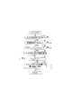
図1に示すように、車両1は、内燃機関としてのエンジン2と、変速機3と、電動機としてのモータジェネレータ4と、駆動輪5と、車両1を総合的に制御するHCU(Hybrid Control Unit)10と、エンジン2を制御するECM(Engine Control Module)11と、変速機3を制御するTCM(Transmission Control Module)12と、ISGCM(Integrated Starter Generator Control Module)13と、INVCM(Invertor Control Module)14と、低電圧BMS(Battery Management System)15と、高電圧BMS16とを含んで構成される。
As shown in FIG. 1, the vehicle 1 includes an engine 2 as an internal combustion engine, a
車両1は、動力源としてエンジン2及びモータジェネレータ4を備え、エンジン2及びモータジェネレータ4の少なくともいずれかの動力により走行するハイブリッド車両である。 The vehicle 1 is a hybrid vehicle that includes an engine 2 and a motor generator 4 as power sources and travels by the power of at least one of the engine 2 and the motor generator 4.
エンジン2には、複数の気筒が形成されている。本実施の形態において、エンジン2は、各気筒に対して、吸気行程、圧縮行程、膨張行程及び排気行程からなる一連の4行程を行うように構成されている。 A plurality of cylinders are formed in the engine 2. In the present embodiment, the engine 2 is configured to perform a series of four strokes including an intake stroke, a compression stroke, an expansion stroke, and an exhaust stroke for each cylinder.
エンジン2には、ISG(Integrated Starter Generator)20と、スタータ21とが連結されている。ISG20は、ベルト22などを介してエンジン2のクランクシャフト18に連結されている。ISG20は、電力が供給されることにより回転することでエンジン2を始動させる電動機の機能と、クランクシャフト18から入力された回転力を電力に変換する発電機の機能とを有する。このように、ISG20は、エンジン2の動力を用いて発電を行うようになっている。ISG20は、本発明における発電機を構成している。
An ISG (Integrated Starter Generator) 20 and a
本実施の形態では、ISG20は、ISGCM13の制御により、電動機として機能することで、エンジン2をアイドリングストップ機能による停止状態から再始動させるようになっている。ISG20は、電動機として機能することで、車両1の走行をアシストすることもできる。
In the present embodiment, the
スタータ21は、図示しないモータとピニオンギヤとを含んで構成されている。スタータ21は、モータを回転させることにより、クランクシャフト18を回転させて、エンジン2に始動時の回転力を与えるようになっている。このように、エンジン2は、スタータ21によって始動され、アイドリングストップ機能による停止状態からISG20によって再始動される。スタータ21及びISG20は、それぞれ本発明における始動装置を構成している。
The
また、エンジン2には、排気管60が接続されている。排気管60の内部には、エンジン2から排出される排気ガスを外部に排出する排気通路が形成されている。排気管60には、エンジン2から排出された排気ガスを浄化する排気ガス浄化装置として、触媒61が設けられている。
Further, an
触媒61は、所定の活性温度以上となると、排気ガスを効率よく浄化することができる。触媒61が活性温度に達していない場合には、ECM11によって触媒61を早期に暖機させる、いわゆる触媒暖機制御が実行される。触媒暖機制御は、エンジン2の点火時期を遅角することによって高温の排気ガスを排気管60に排出することで、触媒61を早期に暖機するものである。
When the
変速機3は、エンジン2から出力された回転を変速し、ドライブシャフト23を介して駆動輪5を駆動するようになっている。変速機3は、平行軸歯車機構からなる常時噛合式の変速機構25と、乾式単板クラッチによって構成されるクラッチ26と、ディファレンシャル機構27と、クラッチアクチュエータ51と、シフトアクチュエータ52と、を備えている。
The
クラッチアクチュエータ51は、TCM12の制御によってクラッチ26の断続(切断と接続)を行うようになっている。シフトアクチュエータ52は、TCM12の制御によって変速機構25の図示しないシフトスリーブを移動して、変速段の切換を行うようになっている。以下、クラッチ26を切断して変速段の切換を行うことを単に変速ともいう。
The
このように、変速機3は、TCM12の制御により自動で変速を行うことが可能な、AMT(Automated Manual Transmission)と称される自動変速機として構成されている。ディファレンシャル機構27は、変速機構25によって出力された動力をドライブシャフト23に伝達するようになっている。
As described above, the
モータジェネレータ4は、ディファレンシャル機構27に対して、チェーン等の動力伝達機構28を介して連結されている。モータジェネレータ4は、電動機として機能する。
The motor generator 4 is connected to the
このように、車両1は、エンジン2とモータジェネレータ4の両方の動力を車両の駆動に用いることが可能なパラレルハイブリッドシステムを構成している。車両1は、エンジン2及びモータジェネレータ4の少なくとも一方が発生する動力により走行する。 In this way, the vehicle 1 constitutes a parallel hybrid system in which the power of both the engine 2 and the motor generator 4 can be used to drive the vehicle. The vehicle 1 travels by the power generated by at least one of the engine 2 and the motor generator 4.
車両1は、エンジン2が発生するエンジントルクのみによる走行と、モータジェネレータ4が発生するモータトルクのみによる走行(EV走行)と、モータトルクをアシストトルクとして用いてエンジン2のエンジントルクをアシストする走行(アシスト走行)が可能である。このように、車両1は、EV走行機能とアシスト走行機能を備えている。 The vehicle 1 runs only by the engine torque generated by the engine 2, runs only by the motor torque generated by the motor generator 4 (EV running), and runs by using the motor torque as an assist torque to assist the engine torque of the engine 2. (Assisted driving) is possible. As described above, the vehicle 1 has an EV traveling function and an assist traveling function.
モータジェネレータ4は、発電機としても機能し、車両1の走行によって発電を行うようになっている。なお、モータジェネレータ4は、変速機3から駆動輪5までの動力伝達経路の何れかの箇所に動力伝達可能に連結されていればよく、必ずしもディファレンシャル機構27に連結される必要はない。
The motor generator 4 also functions as a generator, and generates electricity by traveling the vehicle 1. The motor generator 4 may be connected to any part of the power transmission path from the
車両1は、第1蓄電装置30と、第2蓄電装置31を含む低電圧パワーパック32と、第3蓄電装置33を含む高電圧パワーパック34と、高電圧ケーブル35と、電力供給回路としての低電圧ケーブル36とを備えている。
The vehicle 1 includes a first
第1蓄電装置30、第2蓄電装置31及び第3蓄電装置33は、充電可能な二次電池から構成されている。第1蓄電装置30は鉛電池からなる。第2蓄電装置31は、第1蓄電装置30よりも高出力かつ高エネルギー密度な蓄電装置である。
The first
第2蓄電装置31は、第1蓄電装置30と比較して短い時間で充電が可能である。本実施の形態では、第2蓄電装置31はリチウムイオン電池からなる。なお、第2蓄電装置31はニッケル水素蓄電池であってもよい。
The second
第1蓄電装置30及び第2蓄電装置31は、約12Vの出力電圧を発生するようにセルの個数等が設定された低電圧バッテリである。これら第1蓄電装置30及び第2蓄電装置31は、低電圧ケーブル36を介してISG20と電気的に接続されており、ISG20が発電する発電電力によって充電される。
The first
第3蓄電装置33は、例えば、ニッケル水素蓄電池またはリチウムイオン電池からなる。第3蓄電装置33は、第1蓄電装置30及び第2蓄電装置31より高電圧を発生するようにセルの個数等が設定された高電圧バッテリである。第3蓄電装置33の残容量などの状態は、高電圧BMS16によって管理される。
The third
車両1には、電気負荷としての一般負荷37及び被保護負荷38が搭載されている。一般負荷37及び被保護負荷38は、スタータ21及びISG20以外の電気負荷である。一般負荷37及び被保護負荷38は、本発明における電気負荷を構成している。
The vehicle 1 is equipped with a
被保護負荷38は、常に安定した電力供給が要求される電気負荷である。この被保護負荷38は、車両の横滑りを防止するスタビリティ制御装置38A、操舵輪の操作力を電気的にアシストする電動パワーステアリング制御装置38B、及びヘッドライト38Cを含んでいる。なお、被保護負荷38は、図示しないインストルメントパネルのランプ類及びメータ類並びにカーナビゲーションシステムも含んでいる。
The protected
一般負荷37は、被保護負荷38と比較して安定した電力供給が要求されず、一時的に使用される電気負荷である。一般負荷37には、例えば、図示しないワイパー、及び、エンジン2に冷却風を送風する電動クーリングファンが含まれる。
The
低電圧パワーパック32は、第2蓄電装置31に加えて、スイッチ40、41を有している。第1蓄電装置30及び第2蓄電装置31は、低電圧ケーブル36を介して、スタータ21と、ISG20と、電気負荷としての一般負荷37及び被保護負荷38とに電力を供給可能に接続されている。被保護負荷38に対しては、第1蓄電装置30と第2蓄電装置31とが並列に電気的に接続されている。
The low
スイッチ40は、第2蓄電装置31と被保護負荷38との間の低電圧ケーブル36に設けられている。スイッチ41は、第1蓄電装置30と被保護負荷38との間の低電圧ケーブル36に設けられている。
The
低電圧BMS15は、スイッチ40、41の開閉を制御することで、第2蓄電装置31の充放電及び被保護負荷38への電力供給を制御している。低電圧BMS15は、アイドリングストップによりエンジン2が停止しているときは、スイッチ40を閉じるとともにスイッチ41を開くことで、高出力かつ高エネルギー密度な第2蓄電装置31から被保護負荷38に電力を供給するようになっている。
The low-
低電圧BMS15は、エンジン2をスタータ21によって始動するとき、及び、アイドリングストップ制御によって停止しているエンジン2をISG20によって再始動するときに、スイッチ40を閉じるとともにスイッチ41を開くことで、第1蓄電装置30からスタータ21又はISG20に電力を供給するようになっている。スイッチ40を閉じるとともにスイッチ41を開いた状態では、第1蓄電装置30から一般負荷37にも電力が供給される。
The low-
このように、第1蓄電装置30は、エンジン2を始動する始動装置としてのスタータ21及びISG20に少なくとも電力を供給するようになっている。第2蓄電装置31は、一般負荷37及び被保護負荷38に少なくとも電力を供給するようになっている。第1蓄電装置30は、本発明における第1のバッテリを構成している。第2蓄電装置31は、本発明における第2のバッテリを構成している。
As described above, the first
第2蓄電装置31は、一般負荷37と被保護負荷38の両方に電力を供給可能に接続されているが、常に安定した電力供給が要求される被保護負荷38に優先的に電力を供給するようにスイッチ40、41が低電圧BMS15により制御される。
The second
低電圧BMS15は、第1蓄電装置30及び第2蓄電装置31の充電状態(SOC:State Of Charge、蓄電状態、充電残量、充電容量ともいう)、並びに、一般負荷37及び被保護負荷38への作動要求を考慮しつつ、被保護負荷38の安定した作動することを優先して、スイッチ40、41を上述した例と異なるように制御することがある。
The low-
低電圧BMS15は、ISG20の発電電力によって第2蓄電装置31が充電される場合には、スイッチ40、41の双方を閉じるように制御する。このとき、第2蓄電装置31とISG20とは、電気的に接続される。
The
低電圧BMS15は、第2蓄電装置31の充電が不要とされている場合には、スイッチ40を開くように制御する。このとき、第2蓄電装置31とISG20とは、電気的な接続が遮断される。
The
このように、本実施の形態において、スイッチ40は、第2蓄電装置31とISG20との間の電気的な接続と遮断とを切り替えるものである。スイッチ40は、本発明における切替部を構成している。
As described above, in the present embodiment, the
高電圧パワーパック34は、第3蓄電装置33に加えて、インバータ45を有している。高電圧パワーパック34は、高電圧ケーブル35を介して、モータジェネレータ4に電力を供給可能に接続されている。
The high
インバータ45は、INVCM14の制御により、高電圧ケーブル35にかかる交流電力と、第3蓄電装置33にかかる直流電力とを相互に変換するようになっている。例えば、INVCM14は、モータジェネレータ4を力行させるときには、第3蓄電装置33が放電した直流電力をインバータ45により交流電力に変換させてモータジェネレータ4に供給する。
The
INVCM14は、モータジェネレータ4を回生させるときには、モータジェネレータ4が発電した交流電力をインバータ45により直流電力に変換させて第3蓄電装置33に充電する。
When the motor generator 4 is regenerated, the
HCU10、ECM11、TCM12、ISGCM13と、INVCM14、低電圧BMS15及び高電圧BMS16は、それぞれCPU(Central Processing Unit)と、RAM(Random Access Memory)と、ROM(Read Only Memory)と、バックアップ用のデータなどを保存するフラッシュメモリと、入力ポートと、出力ポートとを備えたコンピュータユニットによって構成されている。 HCU10, ECM11, TCM12, ISGCM13, INVCM14, low voltage BMS15 and high voltage BMS16 are CPU (Central Processing Unit), RAM (Random Access Memory), ROM (Read Only Memory), backup data, etc., respectively. It is composed of a computer unit having a flash memory for storing data, an input port, and an output port.
これらのコンピュータユニットのROMには、各種定数や各種マップ等とともに、当該コンピュータユニットをHCU10、ECM11、TCM12、ISGCM13と、INVCM14、低電圧BMS15及び高電圧BMS16としてそれぞれ機能させるためのプログラムが格納されている。 In the ROM of these computer units, along with various constants and various maps, programs for making the computer unit function as HCU10, ECM11, TCM12, ISGCM13, INVCM14, low voltage BMS15, and high voltage BMS16 are stored. There is.
すなわち、CPUがRAMを作業領域としてROMに格納されたプログラムを実行することにより、これらのコンピュータユニットは、本実施の形態におけるHCU10、ECM11、TCM12、ISGCM13と、INVCM14、低電圧BMS15及び高電圧BMS16としてそれぞれ機能する。 That is, when the CPU executes a program stored in the ROM using the RAM as a work area, these computer units perform the HCU10, ECM11, TCM12, ISGCM13, INVCM14, low voltage BMS15, and high voltage BMS16 in the present embodiment. Each functions as.
本実施の形態において、ECM11は、アイドリングストップ制御を実行するようになっている。このアイドリングストップ制御において、ECM11は、所定の停止条件の成立時にエンジン2を自動的に停止させ、所定の再始動条件の成立時にISGCM13を介してISG20を駆動してエンジン2を再始動させるようになっている。このため、エンジン2の不要なアイドリングが行われなくなり、車両1の燃費を向上させることができる。
In the present embodiment, the
車両1には、CAN(Controller Area Network)等の規格に準拠した車内LAN(Local Area Network)を形成するためのCAN通信線48、49が設けられている。
The vehicle 1 is provided with
HCU10は、INVCM14及び高電圧BMS16にCAN通信線48によって接続されている。HCU10、INVCM14及び高電圧BMS16は、CAN通信線48を介して制御信号等の信号の送受信を相互に行う。
The
HCU10は、ECM11、TCM12、ISGCM13及び低電圧BMS15にCAN通信線49によって接続されている。HCU10、ECM11、TCM12、ISGCM13及び低電圧BMS15は、CAN通信線49を介して制御信号等の信号の送受信を相互に行う。
The
次に、図2を参照して、本実施の形態の車両1に搭載された各種制御装置の機能について説明する。 Next, with reference to FIG. 2, the functions of various control devices mounted on the vehicle 1 of the present embodiment will be described.
図2に示すように、ECM11には、水温センサ70及び点火装置71が接続されている。水温センサ70は、エンジン2の冷却水の温度(以下、「冷却水温」という)を検出するセンサである。点火装置71は、少なくともエンジン2の各気筒に設けられた点火プラグを含んでいる。
As shown in FIG. 2, a
ECM11は、水温センサ70によって検出されたエンジン2の冷却水温が所定の温度未満である場合に、エンジン2の点火時期を遅角することにより触媒61を早期に暖機する触媒暖機制御を実行する触媒暖機制御部110としての機能を有する。ECM11は、触媒暖機制御の実行中に、水温センサ70によって検出されたエンジン2の冷却水温が所定の温度以上となった場合には、触媒暖機制御を終了する。上述した所定の温度は、触媒61が活性温度に達していると判断できる温度であり、予め実験的に求められてECM11のROMに記憶されている。
The
ECM11は、水温センサ70によって検出されたエンジン2の冷却水温が所定の温度未満であるか否かに基づき、触媒暖機制御の実行中であるか否か、すなわち触媒61が暖機中(以下、「触媒暖機中」という)であるかを判定する触媒暖機判定部111としての機能を有する。例えば、ECM11は、水温センサ70によって検出された冷却水温が所定の温度未満である場合には、触媒暖機中であると判定する。
The
ECM11は、上述した冷却水温に限らず、例えば排気温度センサにより検出された排気温度に基づき、触媒暖機制御を実行したり、触媒暖機制御の実行中であるか否かを判定したりしてもよい。この場合、排気管60に図示しない排気温度センサが設けられる。
The
ISGCM13は、ISG20が発電中であるか否かを判定する発電判定部130としての機能を有する。ISGCM13は、例えばISG20の電圧が所定の電圧以上である場合には、ISG20が発電中であると判定することができる。上述の所定の電圧は、少なくとも第1蓄電装置30や第2蓄電装置31の端子電圧(例えば12V)よりも高い電圧(例えば14V等)である。
The
ISGCM13は、HCU10からの指示に基づき、ISG20の出力を所定の出力値以下となるまで徐々に低下させる出力低下制御を実行する出力低下制御部131としての機能を有する。本実施の形態におけるISG20の出力は、ISG20の発電量Pである。
The
具体的には、ISGCM13は、HCU10からの指示に基づきISG20の発電電圧を所定の変化率で低下させることにより、ISG20の発電量Pを所定の発電量Pth以下となるまで徐々に低下させる。前記所定の発電量Pthは、触媒暖機中において、ISG20で発電された発電量の供給先が、第1蓄電装置30と第2蓄電装置31から、第1蓄電装置30のみに変更する場合においても、エンジン回転数が変動しないように算出された発電量である。なお、前記所定の発電量Pthは、第1蓄電装置30の充電状態により、調整可能な値である。
Specifically, the
低電圧BMS15は、第1蓄電装置30及び第2蓄電装置31それぞれのSOCを検出する充電状態検出部150としての機能を有する。低電圧BMS15は、例えば第1蓄電装置30及び第2蓄電装置31それぞれの充放電電流を積算することによりSOCを検出することができる。
The low-
低電圧BMS15は、第2蓄電装置31のSOC(以下、「SOC_2」という)が所定のSOCthに達したか否かを判定する充電状態判定部151としての機能を有する。上述した所定のSOCthは、第2蓄電装置31の満充電を示す上限SOCである。
The low-
所定のSOCthとしては、満充電に満たない値を設定してもよい。この場合、所定のSOCthは、SOC_2がSOCthに達した後、上述した出力低下制御の実行中のISG20の発電量によって満充電となるような値が好ましい。
As the predetermined SOCth, a value less than full charge may be set. In this case, the predetermined SOCth is preferably a value that is fully charged by the amount of power generated by the
HCU10は、ECM11から「触媒暖機中であるか否か」を示す信号を受信するようになっている。HCU10は、ISGCM13から「ISG20が発電中であるか否か」を示す信号を受信するようになっている。HCU10は、低電圧BMS15から「SOC_2がSOCthに達したか否か」を示す信号を受信するようになっている。
The
HCU10は、触媒暖機中に、ISG20の発電によってSOC_2がSOCthに達したことを条件に、ISG20の出力低下制御を実行するよう低電圧BMS15に指示を行う。これにより、ISG20の発電量Pが所定の発電量Pth以下となるまで徐々に低下させられる。
The
ISG20の発電量Pが発電量Pth以下まで低下すると、HCU10は、スイッチ40を開くように低電圧BMS15に指示を行う。これにより、第2蓄電装置31とISG20との間の電気的な接続が遮断される。
When the power generation amount P of the
このように、HCU10は、触媒暖機中に、ISG20の発電によってSOC_2がSOCthに達したことを条件に、ISG20の発電量Pを発電量Pth以下となるまで徐々に低下させた後、第2蓄電装置31とISG20との間の電気的な接続を遮断するようスイッチ40を制御する制御部100としての機能を有する。
As described above, the
次に、図3を参照して、本実施の形態の車両1の電力供給停止処理の流れについて説明する。この電力供給停止処理は、HCU10によって所定の時間間隔で繰り返し実行される。
Next, with reference to FIG. 3, the flow of the power supply stop processing of the vehicle 1 of the present embodiment will be described. This power supply stop processing is repeatedly executed by the
図3に示すように、HCU10は、ISGCM13から受信する信号に基づきISG20が発電中であるか否かを判定する(ステップS1)。HCU10は、ステップS1においてISG20が発電中でないと判定した場合には、電力供給停止処理を終了する。
As shown in FIG. 3, the
HCU10は、ステップS1においてISG20が発電中であると判定した場合には、ECM11から受信する信号に基づき触媒暖機中であるか否かを判定する(ステップS2)。HCU10は、ステップS2において触媒暖機中でないと判定した場合には、電力供給停止処理を終了する。
When the
HCU10は、ステップS2において触媒暖機中であると判定した場合には、低電圧BMS15から受信する信号に基づき、SOC_2がSOCth以上となったか否か、すなわちSOC_2がSOCthに達したか否かを判定する(ステップS3)。 When the HCU10 determines in step S2 that the catalyst is warming up, it determines whether or not SOC_2 is equal to or higher than SOCth, that is, whether or not SOC_2 has reached SOCth, based on the signal received from the low voltage BMS15. Determine (step S3).
HCU10は、ステップS3においてSOC_2がSOCth未満である、すなわちSOC_2がSOCthに達していないと判定した場合には、電力供給停止処理を終了する。
When the
HCU10は、ステップS3においてSOC_2がSOCth以上となった、すなわちSOC_2がSOCthに達したと判定した場合には、ISGCM13を介してISG20の出力低下制御を実行する(ステップS4)。
When it is determined in step S3 that SOC_2 is equal to or higher than SOCth, that is, SOC_2 has reached SOCth, the
次いで、HCU10は、ISG20の発電量Pが所定の発電量Pth以下となったか否かを判定する(ステップS5)。HCU10は、ステップS5において発電量Pが発電量Pthを超えていると判定した場合には、再度、ステップS5の処理を行う。
Next, the
HCU10は、ステップS5において、発電量Pが発電量Pth以下となったと判定した場合には、ISG20から第2蓄電装置31への電力供給を停止する(ステップS6)。具体的には、HCU10は、発電量Pが発電量Pth以下まで低下した場合には、スイッチ40を開くように低電圧BMS15に指示を行う。これにより、第2蓄電装置31とISG20との間の電気的な接続が遮断され、ISG20から第2蓄電装置31への電力の供給が停止する。HCU10は、ステップS6の処理を実行した後、電力供給停止処理を終了する。
When the
図4は、触媒暖機中において、本実施の形態の動作を説明したタイムチャートである。
すなわち、エンジン2の触媒61が暖機中で、かつ第1蓄電装置30と第2蓄電装置31の両方を充電中において、第2蓄電装置31が設定充電状態に達した場合に、第2蓄電装置31を電力供給回路から遮断する過程を説明したタイムチャートである。
FIG. 4 is a time chart illustrating the operation of the present embodiment during catalyst warm-up.
That is, when the
図4の縦軸には、上から順に、エンジン回転数、エンジン駆動力、第2蓄電装置31の充電状態、ISG20の発電量、第2蓄電装置31とISG20の接続状態が表される。
The vertical axis of FIG. 4 shows, in order from the top, the engine speed, the engine driving force, the charging state of the second
ISG20と、第1蓄電装置30と第2蓄電装置31とが接続され、算出された発電量により両蓄電装置30、31は充電される(時刻t0)。
The
時刻t0以降もISG20から両蓄電装置30、31への充電が継続し、やがて第2蓄電装置31の充電状態がSOCthに達すると、ISG20から第2蓄電装置31への電力供給回路を遮断する準備が開始される。すなわち、ISG20の発電量を減少させる。これとともに、ISG20を駆動するエンジン2の駆動力も減少する(時刻t1)。
After time t0, charging of both
ISG20の発電量が減少し続け所定の発電量Pthに達すると、減少を停止し所定の発電量Pthを維持し続ける(時刻t2)。
When the power generation amount of the
時刻t2での発電量Pthへの到達により、HCU10は、ISG20と第2蓄電装置31との接続を遮断する(時刻t3)。
Upon reaching the power generation amount Pth at time t2, the
以上のように、本実施の形態に係る車両1は、触媒暖機中にISG20の発電によってSOC_2がSOCthに達したことを条件に、ISG20の発電量Pを所定の発電量Pth以下となるまで徐々に低下させた後、第2蓄電装置31とISG20との間の電気的な接続を遮断する。このため、本実施の形態に係る車両1は、触媒暖機中であってもエンジン回転数の吹き上がりを抑制することができる。この結果、運転者の意図しないエンジン2の挙動の発生を抑制することができる。
As described above, in the vehicle 1 according to the present embodiment, the power generation amount P of the ISG20 becomes equal to or less than the predetermined power generation amount Pth on the condition that the SOC_2 reaches the SOCth by the power generation of the ISG20 during the catalyst warm-up. After gradually lowering the voltage, the electrical connection between the second
本実施の形態の第1蓄電装置30は鉛電池からなり、第2蓄電装置31はリチウムイオン電池からなる。リチウムイオン電池の満充電を示す上限SOCは、鉛電池の上限SOCよりも低く設定されている。このため、第1蓄電装置30と第2蓄電装置31とが同時充電されている場合には、第2蓄電装置31のSOC_2が第1蓄電装置30よりも早く上限SOCに達する、すなわち所定のSOCthに達することが多い。
The first
したがって、本実施の形態に係る車両1は、リチウムイオン電池が満充電に達した場合に、出力低下制御を実行してリチウムイオン電池とISG20との電気的な接続を遮断するので、実用的である。
Therefore, the vehicle 1 according to the present embodiment is practical because when the lithium ion battery reaches full charge, the output reduction control is executed to cut off the electrical connection between the lithium ion battery and the
なお、本実施の形態では、ハイブリッド車両に本発明を適用した例について説明したが、図5に示すようなアイドルストップ機能を有する車両201に本発明を適用してもよい。
In the present embodiment, an example in which the present invention is applied to a hybrid vehicle has been described, but the present invention may be applied to a
図5に示すように、車両201は、本実施の形態の車両1とはモータジェネレータ4、HCU10及び高電圧パワーパック34等を備えていない点で異なる。車両201においては、HCU10に代わってECU(Electric Control Unit)210が図3に示した電力供給停止処理を実行する。
As shown in FIG. 5, the
車両201にあっても、触媒暖機中であってもエンジン回転数の吹き上がりを抑制することができる。この結果、運転者の意図しないエンジン2の挙動の発生を抑制することができる。
Even in the
本発明の実施の形態を開示したが、当業者によっては本発明の範囲を逸脱することなく変更が加えられうることは明白である。すべてのこのような修正および等価物が次の請求項に含まれることが意図されている。 Although embodiments of the present invention have been disclosed, it will be apparent to those skilled in the art that modifications may be made without departing from the scope of the invention. All such modifications and equivalents are intended to be included in the following claims.
1、201 車両
2 エンジン(内燃機関)
4 モータジェネレータ
10 HCU
11 ECM
13 ISGCM
15 低電圧BMS
20 ISG(発電機)
21 スタータ
30 第1蓄電装置(第1のバッテリ)
31 第2蓄電装置(第2のバッテリ)
36 低電圧ケーブル(電力供給回路)
37 一般負荷(電気負荷)
38 被保護負荷(電気負荷)
40 スイッチ
61 触媒(排気ガス浄化装置)
100 制御部
110 触媒暖機制御部
111 触媒暖機判定部
130 発電判定部
131 出力低下制御部
150 充電状態検出部
151 充電状態判定部
210 ECU
1,201 Vehicle 2 Engine (internal combustion engine)
4
11 ECM
13 ISGCM
15 Low voltage BMS
20 ISG (generator)
21
31 Second power storage device (second battery)
36 Low voltage cable (power supply circuit)
37 General load (electrical load)
38 Protected load (electrical load)
40
100
Claims (5)
前記内燃機関の排気通路に設けられた排気ガス浄化装置と、
前記内燃機関の動力を利用して発電する発電機と、
前記発電機から第1のバッテリと第2のバッテリとに電力を供給する電力供給回路とを備えた車両であって、
前記第2のバッテリの充電状態を検出する充電状態検出部と、
前記内燃機関の点火時期の遅角による前記排気ガス浄化装置の暖機時において、前記発電機による発電により前記第2のバッテリの充電状態が設定値を超えた場合には、前記発電機の出力を所定の出力値以下となるまで徐々に低下させるとともに前記内燃機関の駆動力が低下した後、前記発電機から前記第2のバッテリへの電力供給回路を遮断する制御部と、を備えることを特徴とする車両。 With an internal combustion engine
An exhaust gas purification device provided in the exhaust passage of the internal combustion engine and
A generator that uses the power of the internal combustion engine to generate electricity,
A vehicle provided with a power supply circuit for supplying electric power from the generator to the first battery and the second battery.
A charge state detection unit that detects the charge state of the second battery ,
When the exhaust gas purification device is warmed up due to the retardation of the ignition timing of the internal combustion engine, if the charge state of the second battery exceeds the set value due to the power generation by the generator, the output of the generator after driving force gradually decreases Rutotomoni the internal combustion engine is lowered until equal to or less than a predetermined output value, and a control unit to cut off the power supply circuit to the second battery from the generator A vehicle characterized by that.
前記第2のバッテリは、電気負荷を作動するための電力を供給することを特徴とする請求項1から請求項3のいずれか1項に記載の車両。 The first battery supplies at least power for starting the internal combustion engine.
The vehicle according to any one of claims 1 to 3, wherein the second battery supplies electric power for operating an electric load.
前記第2のバッテリは、リチウムイオン電池であることを特徴とする請求項1から請求項4のいずれか1項に記載の車両。 The first battery is a lead battery and
The vehicle according to any one of claims 1 to 4, wherein the second battery is a lithium ion battery.
Priority Applications (1)
| Application Number | Priority Date | Filing Date | Title |
|---|---|---|---|
| JP2016097683A JP6795910B2 (en) | 2016-05-16 | 2016-05-16 | vehicle |
Applications Claiming Priority (1)
| Application Number | Priority Date | Filing Date | Title |
|---|---|---|---|
| JP2016097683A JP6795910B2 (en) | 2016-05-16 | 2016-05-16 | vehicle |
Publications (3)
| Publication Number | Publication Date |
|---|---|
| JP2017206045A JP2017206045A (en) | 2017-11-24 |
| JP2017206045A5 JP2017206045A5 (en) | 2018-04-26 |
| JP6795910B2 true JP6795910B2 (en) | 2020-12-02 |
Family
ID=60415165
Family Applications (1)
| Application Number | Title | Priority Date | Filing Date |
|---|---|---|---|
| JP2016097683A Active JP6795910B2 (en) | 2016-05-16 | 2016-05-16 | vehicle |
Country Status (1)
| Country | Link |
|---|---|
| JP (1) | JP6795910B2 (en) |
Families Citing this family (1)
| Publication number | Priority date | Publication date | Assignee | Title |
|---|---|---|---|---|
| JP7347997B2 (en) | 2019-08-29 | 2023-09-20 | 株式会社Subaru | Vehicle control device |
Family Cites Families (4)
| Publication number | Priority date | Publication date | Assignee | Title |
|---|---|---|---|---|
| JP4023030B2 (en) * | 1999-05-14 | 2007-12-19 | トヨタ自動車株式会社 | POWER OUTPUT DEVICE, HYBRID VEHICLE HAVING SAME, AND METHOD FOR CONTROLLING POWER OUTPUT DEVICE |
| JP5110327B2 (en) * | 2009-09-28 | 2012-12-26 | 三菱自動車工業株式会社 | Engine exhaust purification system |
| JP2015083409A (en) * | 2013-10-25 | 2015-04-30 | トヨタ自動車株式会社 | Hybrid vehicle |
| JP6244987B2 (en) * | 2014-03-05 | 2017-12-13 | 株式会社デンソー | Power system |
-
2016
- 2016-05-16 JP JP2016097683A patent/JP6795910B2/en active Active
Also Published As
| Publication number | Publication date |
|---|---|
| JP2017206045A (en) | 2017-11-24 |
Similar Documents
| Publication | Publication Date | Title |
|---|---|---|
| JP2003219564A (en) | Controller for storage device in vehicle | |
| JP6759979B2 (en) | Vehicle power generation control device | |
| CN106976397B (en) | Hybrid vehicle | |
| JP6819214B2 (en) | Automatic engine stop device | |
| JP6582928B2 (en) | Shift control device for hybrid vehicle | |
| JP6795910B2 (en) | vehicle | |
| JP6476936B2 (en) | Drive control device | |
| JP2017100472A (en) | Charge control device for hybrid vehicle | |
| JP6819215B2 (en) | Automatic engine stop device | |
| JP2017114322A (en) | Hybrid vehicle | |
| JP2018069947A (en) | Drive control device of hybrid vehicle | |
| JP2017105377A (en) | Drive control device of hybrid vehicle | |
| JP6428658B2 (en) | Hybrid vehicle | |
| JP6645383B2 (en) | Hybrid car | |
| JP6634807B2 (en) | Drive control device for hybrid vehicle | |
| JP6977321B2 (en) | Vehicle control device | |
| JP2019202742A (en) | Hybrid vehicle | |
| JP6878828B2 (en) | Hybrid vehicle engine control | |
| JP7204509B2 (en) | vehicle | |
| JP7204003B2 (en) | vehicle controller | |
| JP7222737B2 (en) | vehicle | |
| JP2017100473A (en) | Motor assist control device of hybrid vehicle | |
| JP6876372B2 (en) | Hybrid vehicle | |
| JP2017114321A (en) | Hybrid vehicle | |
| JP6645178B2 (en) | Control device for hybrid vehicle |
Legal Events
| Date | Code | Title | Description |
|---|---|---|---|
| A521 | Written amendment |
Free format text: JAPANESE INTERMEDIATE CODE: A523 Effective date: 20180314 |
|
| A621 | Written request for application examination |
Free format text: JAPANESE INTERMEDIATE CODE: A621 Effective date: 20180314 |
|
| A977 | Report on retrieval |
Free format text: JAPANESE INTERMEDIATE CODE: A971007 Effective date: 20181122 |
|
| A131 | Notification of reasons for refusal |
Free format text: JAPANESE INTERMEDIATE CODE: A131 Effective date: 20181204 |
|
| A521 | Written amendment |
Free format text: JAPANESE INTERMEDIATE CODE: A523 Effective date: 20190125 |
|
| A131 | Notification of reasons for refusal |
Free format text: JAPANESE INTERMEDIATE CODE: A131 Effective date: 20190423 |
|
| A521 | Written amendment |
Free format text: JAPANESE INTERMEDIATE CODE: A523 Effective date: 20190620 |
|
| A02 | Decision of refusal |
Free format text: JAPANESE INTERMEDIATE CODE: A02 Effective date: 20190827 |
|
| C60 | Trial request (containing other claim documents, opposition documents) |
Free format text: JAPANESE INTERMEDIATE CODE: C60 Effective date: 20191126 |
|
| C22 | Notice of designation (change) of administrative judge |
Free format text: JAPANESE INTERMEDIATE CODE: C22 Effective date: 20200428 |
|
| C13 | Notice of reasons for refusal |
Free format text: JAPANESE INTERMEDIATE CODE: C13 Effective date: 20200714 |
|
| A521 | Written amendment |
Free format text: JAPANESE INTERMEDIATE CODE: A523 Effective date: 20200914 |
|
| C23 | Notice of termination of proceedings |
Free format text: JAPANESE INTERMEDIATE CODE: C23 Effective date: 20201006 |
|
| C03 | Trial/appeal decision taken |
Free format text: JAPANESE INTERMEDIATE CODE: C03 Effective date: 20201110 |
|
| C30A | Notification sent |
Free format text: JAPANESE INTERMEDIATE CODE: C3012 Effective date: 20201110 |
|
| A61 | First payment of annual fees (during grant procedure) |
Free format text: JAPANESE INTERMEDIATE CODE: A61 Effective date: 20201113 |
|
| R150 | Certificate of patent or registration of utility model |
Ref document number: 6795910 Country of ref document: JP Free format text: JAPANESE INTERMEDIATE CODE: R150 |