JP6795701B2 - System for navigation and visualization of body passages - Google Patents
System for navigation and visualization of body passages Download PDFInfo
- Publication number
- JP6795701B2 JP6795701B2 JP2019534752A JP2019534752A JP6795701B2 JP 6795701 B2 JP6795701 B2 JP 6795701B2 JP 2019534752 A JP2019534752 A JP 2019534752A JP 2019534752 A JP2019534752 A JP 2019534752A JP 6795701 B2 JP6795701 B2 JP 6795701B2
- Authority
- JP
- Japan
- Prior art keywords
- end cap
- working channel
- elongated member
- ultrasonic probe
- tissue
- Prior art date
- Legal status (The legal status is an assumption and is not a legal conclusion. Google has not performed a legal analysis and makes no representation as to the accuracy of the status listed.)
- Active
Links
- 238000012800 visualization Methods 0.000 title description 11
- 239000000523 sample Substances 0.000 claims description 53
- 239000012530 fluid Substances 0.000 claims description 28
- 238000005070 sampling Methods 0.000 claims description 28
- 239000000463 material Substances 0.000 claims description 19
- 230000007704 transition Effects 0.000 claims description 10
- 238000002604 ultrasonography Methods 0.000 claims description 9
- 239000004020 conductor Substances 0.000 claims description 5
- 239000004033 plastic Substances 0.000 claims description 4
- 229920003023 plastic Polymers 0.000 claims description 4
- 238000001574 biopsy Methods 0.000 description 38
- 210000004072 lung Anatomy 0.000 description 28
- 238000000034 method Methods 0.000 description 11
- 230000000472 traumatic effect Effects 0.000 description 5
- 239000000853 adhesive Substances 0.000 description 4
- 230000001070 adhesive effect Effects 0.000 description 4
- 230000008901 benefit Effects 0.000 description 4
- 230000002093 peripheral effect Effects 0.000 description 4
- 150000003839 salts Chemical class 0.000 description 4
- XLYOFNOQVPJJNP-UHFFFAOYSA-N water Substances O XLYOFNOQVPJJNP-UHFFFAOYSA-N 0.000 description 4
- 229920001223 polyethylene glycol Polymers 0.000 description 3
- 239000004593 Epoxy Substances 0.000 description 2
- 239000002202 Polyethylene glycol Substances 0.000 description 2
- 229920001903 high density polyethylene Polymers 0.000 description 2
- 239000004700 high-density polyethylene Substances 0.000 description 2
- 230000003100 immobilizing effect Effects 0.000 description 2
- 230000001788 irregular Effects 0.000 description 2
- -1 polyethylene Polymers 0.000 description 2
- 229920000139 polyethylene terephthalate Polymers 0.000 description 2
- 239000005020 polyethylene terephthalate Substances 0.000 description 2
- 229920000642 polymer Polymers 0.000 description 2
- 230000002685 pulmonary effect Effects 0.000 description 2
- 239000011347 resin Substances 0.000 description 2
- 229920005989 resin Polymers 0.000 description 2
- 239000004698 Polyethylene Substances 0.000 description 1
- 206010056342 Pulmonary mass Diseases 0.000 description 1
- 230000006399 behavior Effects 0.000 description 1
- 238000005219 brazing Methods 0.000 description 1
- 210000001072 colon Anatomy 0.000 description 1
- 238000004891 communication Methods 0.000 description 1
- 230000006835 compression Effects 0.000 description 1
- 238000007906 compression Methods 0.000 description 1
- 230000002183 duodenal effect Effects 0.000 description 1
- 229920001971 elastomer Polymers 0.000 description 1
- 239000000806 elastomer Substances 0.000 description 1
- 238000001839 endoscopy Methods 0.000 description 1
- 210000003238 esophagus Anatomy 0.000 description 1
- 210000001035 gastrointestinal tract Anatomy 0.000 description 1
- 230000001771 impaired effect Effects 0.000 description 1
- 229920000126 latex Polymers 0.000 description 1
- 239000004816 latex Substances 0.000 description 1
- 238000012986 modification Methods 0.000 description 1
- 230000004048 modification Effects 0.000 description 1
- 230000000149 penetrating effect Effects 0.000 description 1
- 230000035515 penetration Effects 0.000 description 1
- 229920000728 polyester Polymers 0.000 description 1
- 229920000573 polyethylene Polymers 0.000 description 1
- 229920001296 polysiloxane Polymers 0.000 description 1
- 238000005476 soldering Methods 0.000 description 1
- 210000002784 stomach Anatomy 0.000 description 1
- 239000000126 substance Substances 0.000 description 1
- 210000002229 urogenital system Anatomy 0.000 description 1
- 210000005166 vasculature Anatomy 0.000 description 1
- 229940099259 vaseline Drugs 0.000 description 1
- 238000003466 welding Methods 0.000 description 1
Images


Classifications
-
- A—HUMAN NECESSITIES
- A61—MEDICAL OR VETERINARY SCIENCE; HYGIENE
- A61B—DIAGNOSIS; SURGERY; IDENTIFICATION
- A61B10/00—Other methods or instruments for diagnosis, e.g. instruments for taking a cell sample, for biopsy, for vaccination diagnosis; Sex determination; Ovulation-period determination; Throat striking implements
- A61B10/02—Instruments for taking cell samples or for biopsy
- A61B10/04—Endoscopic instruments
-
- A—HUMAN NECESSITIES
- A61—MEDICAL OR VETERINARY SCIENCE; HYGIENE
- A61B—DIAGNOSIS; SURGERY; IDENTIFICATION
- A61B1/00—Instruments for performing medical examinations of the interior of cavities or tubes of the body by visual or photographical inspection, e.g. endoscopes; Illuminating arrangements therefor
- A61B1/00064—Constructional details of the endoscope body
- A61B1/00071—Insertion part of the endoscope body
- A61B1/0008—Insertion part of the endoscope body characterised by distal tip features
- A61B1/00089—Hoods
-
- A—HUMAN NECESSITIES
- A61—MEDICAL OR VETERINARY SCIENCE; HYGIENE
- A61B—DIAGNOSIS; SURGERY; IDENTIFICATION
- A61B1/00—Instruments for performing medical examinations of the interior of cavities or tubes of the body by visual or photographical inspection, e.g. endoscopes; Illuminating arrangements therefor
- A61B1/012—Instruments for performing medical examinations of the interior of cavities or tubes of the body by visual or photographical inspection, e.g. endoscopes; Illuminating arrangements therefor characterised by internal passages or accessories therefor
- A61B1/018—Instruments for performing medical examinations of the interior of cavities or tubes of the body by visual or photographical inspection, e.g. endoscopes; Illuminating arrangements therefor characterised by internal passages or accessories therefor for receiving instruments
-
- A—HUMAN NECESSITIES
- A61—MEDICAL OR VETERINARY SCIENCE; HYGIENE
- A61B—DIAGNOSIS; SURGERY; IDENTIFICATION
- A61B10/00—Other methods or instruments for diagnosis, e.g. instruments for taking a cell sample, for biopsy, for vaccination diagnosis; Sex determination; Ovulation-period determination; Throat striking implements
- A61B10/02—Instruments for taking cell samples or for biopsy
- A61B10/0233—Pointed or sharp biopsy instruments
-
- A—HUMAN NECESSITIES
- A61—MEDICAL OR VETERINARY SCIENCE; HYGIENE
- A61B—DIAGNOSIS; SURGERY; IDENTIFICATION
- A61B34/00—Computer-aided surgery; Manipulators or robots specially adapted for use in surgery
- A61B34/20—Surgical navigation systems; Devices for tracking or guiding surgical instruments, e.g. for frameless stereotaxis
-
- A—HUMAN NECESSITIES
- A61—MEDICAL OR VETERINARY SCIENCE; HYGIENE
- A61B—DIAGNOSIS; SURGERY; IDENTIFICATION
- A61B8/00—Diagnosis using ultrasonic, sonic or infrasonic waves
- A61B8/08—Detecting organic movements or changes, e.g. tumours, cysts, swellings
- A61B8/0833—Detecting organic movements or changes, e.g. tumours, cysts, swellings involving detecting or locating foreign bodies or organic structures
- A61B8/0841—Detecting organic movements or changes, e.g. tumours, cysts, swellings involving detecting or locating foreign bodies or organic structures for locating instruments
-
- A—HUMAN NECESSITIES
- A61—MEDICAL OR VETERINARY SCIENCE; HYGIENE
- A61B—DIAGNOSIS; SURGERY; IDENTIFICATION
- A61B8/00—Diagnosis using ultrasonic, sonic or infrasonic waves
- A61B8/08—Detecting organic movements or changes, e.g. tumours, cysts, swellings
- A61B8/0833—Detecting organic movements or changes, e.g. tumours, cysts, swellings involving detecting or locating foreign bodies or organic structures
- A61B8/085—Detecting organic movements or changes, e.g. tumours, cysts, swellings involving detecting or locating foreign bodies or organic structures for locating body or organic structures, e.g. tumours, calculi, blood vessels, nodules
-
- A—HUMAN NECESSITIES
- A61—MEDICAL OR VETERINARY SCIENCE; HYGIENE
- A61B—DIAGNOSIS; SURGERY; IDENTIFICATION
- A61B8/00—Diagnosis using ultrasonic, sonic or infrasonic waves
- A61B8/12—Diagnosis using ultrasonic, sonic or infrasonic waves in body cavities or body tracts, e.g. by using catheters
-
- A—HUMAN NECESSITIES
- A61—MEDICAL OR VETERINARY SCIENCE; HYGIENE
- A61B—DIAGNOSIS; SURGERY; IDENTIFICATION
- A61B8/00—Diagnosis using ultrasonic, sonic or infrasonic waves
- A61B8/42—Details of probe positioning or probe attachment to the patient
-
- A—HUMAN NECESSITIES
- A61—MEDICAL OR VETERINARY SCIENCE; HYGIENE
- A61B—DIAGNOSIS; SURGERY; IDENTIFICATION
- A61B8/00—Diagnosis using ultrasonic, sonic or infrasonic waves
- A61B8/44—Constructional features of the ultrasonic, sonic or infrasonic diagnostic device
- A61B8/4444—Constructional features of the ultrasonic, sonic or infrasonic diagnostic device related to the probe
- A61B8/445—Details of catheter construction
-
- A—HUMAN NECESSITIES
- A61—MEDICAL OR VETERINARY SCIENCE; HYGIENE
- A61B—DIAGNOSIS; SURGERY; IDENTIFICATION
- A61B8/00—Diagnosis using ultrasonic, sonic or infrasonic waves
- A61B8/44—Constructional features of the ultrasonic, sonic or infrasonic diagnostic device
- A61B8/4444—Constructional features of the ultrasonic, sonic or infrasonic diagnostic device related to the probe
- A61B8/4455—Features of the external shape of the probe, e.g. ergonomic aspects
-
- A—HUMAN NECESSITIES
- A61—MEDICAL OR VETERINARY SCIENCE; HYGIENE
- A61B—DIAGNOSIS; SURGERY; IDENTIFICATION
- A61B90/00—Instruments, implements or accessories specially adapted for surgery or diagnosis and not covered by any of the groups A61B1/00 - A61B50/00, e.g. for luxation treatment or for protecting wound edges
- A61B90/36—Image-producing devices or illumination devices not otherwise provided for
- A61B90/37—Surgical systems with images on a monitor during operation
-
- A—HUMAN NECESSITIES
- A61—MEDICAL OR VETERINARY SCIENCE; HYGIENE
- A61B—DIAGNOSIS; SURGERY; IDENTIFICATION
- A61B10/00—Other methods or instruments for diagnosis, e.g. instruments for taking a cell sample, for biopsy, for vaccination diagnosis; Sex determination; Ovulation-period determination; Throat striking implements
- A61B10/02—Instruments for taking cell samples or for biopsy
- A61B10/04—Endoscopic instruments
- A61B2010/045—Needles
-
- A—HUMAN NECESSITIES
- A61—MEDICAL OR VETERINARY SCIENCE; HYGIENE
- A61B—DIAGNOSIS; SURGERY; IDENTIFICATION
- A61B17/00—Surgical instruments, devices or methods, e.g. tourniquets
- A61B17/00234—Surgical instruments, devices or methods, e.g. tourniquets for minimally invasive surgery
- A61B2017/00292—Surgical instruments, devices or methods, e.g. tourniquets for minimally invasive surgery mounted on or guided by flexible, e.g. catheter-like, means
-
- A—HUMAN NECESSITIES
- A61—MEDICAL OR VETERINARY SCIENCE; HYGIENE
- A61B—DIAGNOSIS; SURGERY; IDENTIFICATION
- A61B90/00—Instruments, implements or accessories specially adapted for surgery or diagnosis and not covered by any of the groups A61B1/00 - A61B50/00, e.g. for luxation treatment or for protecting wound edges
- A61B90/36—Image-producing devices or illumination devices not otherwise provided for
- A61B90/37—Surgical systems with images on a monitor during operation
- A61B2090/378—Surgical systems with images on a monitor during operation using ultrasound
- A61B2090/3782—Surgical systems with images on a monitor during operation using ultrasound transmitter or receiver in catheter or minimal invasive instrument
-
- A—HUMAN NECESSITIES
- A61—MEDICAL OR VETERINARY SCIENCE; HYGIENE
- A61B—DIAGNOSIS; SURGERY; IDENTIFICATION
- A61B8/00—Diagnosis using ultrasonic, sonic or infrasonic waves
- A61B8/44—Constructional features of the ultrasonic, sonic or infrasonic diagnostic device
- A61B8/4444—Constructional features of the ultrasonic, sonic or infrasonic diagnostic device related to the probe
- A61B8/4461—Features of the scanning mechanism, e.g. for moving the transducer within the housing of the probe
Description
本開示は、身体通路を通る改良されたナビゲーション、ならびに標的組織の向上した可視化および試料採取のためのシステムおよび方法に関する。 The present disclosure relates to improved navigation through body passages, as well as systems and methods for improved visualization and sampling of target tissues.
超音波プローブによる身体通路内におけるナビゲーションおよび可視化は、プローブへの損傷を防止したり、また可視化を最適化したりすることが困難である。例えば、ラジアル走査式気管支腔内超音波(radial endobronchial ultrasound:R−EBUS)は、臨床症状が肺系統内の組織生検が必要であることを示す場合に低侵襲性の選択肢を提供する。そのような肺組織生検システムの超音波要素は、肺通路内の標的結節の可視化に重要である。超音波エネルギーは、特定の密度および屈折率を有するポリマーのような物質を通ってのみ伝播することができ、そのため超音波プローブが送達カテーテルの遠位端部を越えて延在可能であることを必要とする。肺周辺の寸法的制約により、超音波プローブの露出部は、小さく、かつ脆弱である傾向にあり、従って損傷を受けやすい。露出部上においてテーパー状/非外傷性の先端を有していないことにより、肺の通路の壁に沿った緩やかな隆起でさえ、超音波プローブをねじれさせ、かつ/または破損させ得ることがある。加えて、より大きな肺通路内における標的結節の可視化は、超音波信号の伝播を阻止/減衰させる超音波プローブと組織壁との間の開放空間(例えば空気)の存在によって損なわれる傾向にある。 Navigation and visualization within the body passage with an ultrasonic probe is difficult to prevent damage to the probe and to optimize visualization. For example, radial scanning bronchial ultrasonography (R-EBUS) provides a minimally invasive option when clinical manifestations indicate that tissue biopsy within the lung system is required. The ultrasonic component of such a lung tissue biopsy system is important for visualization of target nodules in the lung passage. Ultrasonic energy can only propagate through substances such as polymers with a particular density and index of refraction, so that the ultrasonic probe can extend beyond the distal end of the delivery catheter. I need. Due to dimensional constraints around the lungs, exposed areas of the ultrasonic probe tend to be small and fragile and therefore susceptible to damage. By not having a tapered / non-traumatic tip on the exposed area, even a gentle ridge along the wall of the lung passage can twist and / or break the ultrasound probe. .. In addition, visualization of target nodules within the larger lung passage tends to be impaired by the presence of open space (eg, air) between the ultrasonic probe and the tissue wall that blocks / attenuates the propagation of ultrasonic signals.
従って、狭い身体通路を通る改良されたナビゲーションおよび大きな身体通路内における向上した標的組織の可視化を可能にするシステムによって、様々な利点が実現され得る。 Therefore, various benefits may be realized by systems that allow improved navigation through narrow body passages and improved visualization of target tissue within large body passages.
本開示は、その様々な態様で、肺内視鏡検査の分野のような医療分野において、身体通路を通る改良されたナビゲーションおよび標的組織の向上した可視化および試料採取を可能にし得る試料採取システムの利点を提供する。様々な実施形態において、試料採取システムは、超音波プローブの露出部を保護し、かつ標的組織の可視化の向上のために身体通路の壁との接触および超音波信号の伝播を高めるエンドキャップを備える。 The present disclosure is a sampling system that, in various aspects thereof, may enable improved navigation through the body passage and improved visualization and sampling of target tissue in the medical field, such as the field of lung endoscopy. Provide benefits. In various embodiments, the sampling system comprises an end cap that protects the exposed portion of the ultrasonic probe and enhances contact with the walls of the body passage and propagation of the ultrasonic signal for better visibility of the target tissue. ..
一態様において、本開示は、それぞれの第1開口および第2開口を画定する第1ワーキングチャネルおよび第2ワーキングチャネルを含む長尺状部材を備えたシステムに関連する。超音波プローブは、超音波プローブの遠位部分が長尺状部材の遠位端部を越えて遠位に延在可能となるように、第1ワーキングチャネル内に配置されている。エンドキャップは、超音波プローブが第1開口の外側に延在するときに超音波プローブの遠位部分を包囲するように、長尺状部材の遠位端部に取り付けられている。組織試料採取要素は、第2ワーキングチャネル内に摺動可能に配置されている。第1ワーキングチャネルは、長尺状部材の近位端部と遠位端部との間に延びて、第1開口を画定する。第2ワーキングチャネルは、長尺状部材の近位端部と長尺状部材の外面との間に延びて、第2開口を画定する。第2ワーキングチャネルは、長尺状部材の遠位部分内で第2開口において傾斜面を画定する。エンドキャップは硬質プラスチック材料を含む。エンドキャップは導電性物質で充填されている。エンドキャップは、第1形態と第2形態との間を移行するように構成された拡張可能部材を備える。拡張可能部材は、拡張可能部材の内部に膨張流体を流入させることにより、第1形態から第2形態に移行可能である。拡張可能部材は、拡張可能部材の内部領域から膨張流体を流出させることにより、第2形態から第1形態に移行可能である。超音波プローブは第1ワーキングチャネル内に固定されていてもよい。超音波プローブは第1ワーキングチャネル内において摺動可能であってもよい。エンドキャップは、長尺状部材の遠位端部の周囲に取り付けられていてもよい。エンドキャップは、長尺状部材の遠位端部の第1開口のあたりに(例えば、周りに)取り付けられていてもよい。 In one aspect, the present disclosure relates to a system comprising an elongated member comprising a first working channel and a second working channel defining the first and second openings, respectively. The ultrasonic probe is arranged within the first working channel so that the distal portion of the ultrasonic probe can extend distally beyond the distal end of the elongated member. The end cap is attached to the distal end of the elongated member so that it surrounds the distal portion of the ultrasonic probe as it extends outside the first opening. The tissue sampling element is slidably arranged within the second working channel. The first working channel extends between the proximal and distal ends of the elongated member to define the first opening. The second working channel extends between the proximal end of the elongated member and the outer surface of the elongated member to define a second opening. The second working channel defines an inclined surface at the second opening within the distal portion of the elongated member. The end cap contains a hard plastic material. The end cap is filled with a conductive material. The end cap comprises an expandable member configured to transition between the first and second forms. The expandable member can shift from the first form to the second form by allowing an expanding fluid to flow into the expandable member. The expandable member can shift from the second form to the first form by letting the expanding fluid flow out from the internal region of the expandable member. The ultrasonic probe may be anchored in the first working channel. The ultrasonic probe may be slidable within the first working channel. The end cap may be attached around the distal end of the elongated member. The end cap may be attached around (eg, around) the first opening at the distal end of the elongated member.
別の態様において、本開示は、それぞれの第1開口および第2開口を画定する第1ワーキングチャネルおよび第2ワーキングチャネルを含む長尺状部材を備えたシステムに関連する。超音波プローブは、超音波プローブの遠位部分が長尺状部材の遠位端部を越えて遠位に延在可能となるように、第1ワーキングチャネル内に配置されている。エンドキャップは超音波プローブの遠位部分に取り付けられている。組織試料採取要素は、第2ワーキングチャネル内に摺動可能に配置されている。第1ワーキングチャネルは、長尺状部材の近位端部と遠位端部との間に延びて、第1開口を画定する。第2ワーキングチャネルは、長尺状部材の近位端部と長尺状部材の外面との間に延びて、第2開口を画定する。第2ワーキングチャネルは、長尺状部材の遠位部分内で第2開口において傾斜面を画定する。エンドキャップは、第1形態と第2形態との間を移行するように構成された拡張可能部材を備える。拡張可能部材は、拡張可能部材の内部に膨張流体を流入させることにより、第1形態から第2形態に移行可能である。拡張可能部材は、拡張可能部材の内部領域から膨張流体を流出させることにより、第2形態から第1形態に移行可能である。超音波プローブは第1ワーキングチャネル内に固定されていてもよい。超音波プローブは第1ワーキングチャネル内において摺動可能であってもよい。 In another aspect, the present disclosure relates to a system comprising an elongated member comprising a first working channel and a second working channel defining the first and second openings, respectively. The ultrasonic probe is arranged within the first working channel so that the distal portion of the ultrasonic probe can extend distally beyond the distal end of the elongated member. The end cap is attached to the distal portion of the ultrasonic probe. The tissue sampling element is slidably arranged within the second working channel. The first working channel extends between the proximal and distal ends of the elongated member to define the first opening. The second working channel extends between the proximal end of the elongated member and the outer surface of the elongated member to define a second opening. The second working channel defines an inclined surface at the second opening within the distal portion of the elongated member. The end cap comprises an expandable member configured to transition between the first and second forms. The expandable member can shift from the first form to the second form by allowing an expanding fluid to flow into the expandable member. The expandable member can shift from the second form to the first form by letting the expanding fluid flow out from the internal region of the expandable member. The ultrasonic probe may be anchored in the first working channel. The ultrasonic probe may be slidable within the first working channel.
別の態様において、本開示は、身体通路内にシステムを進めることを含む方法に関連する。システムは、長尺状部材と、長尺状部材の第1ワーキングチャネル内に配置された超音波プローブと、長尺状部材の遠位端部に取り付けられた拡張可能部材とを備える。超音波プローブの遠位部分は、長尺状部材の遠位端部を越えて遠位に延びる。拡張可能部材は、超音波プローブの遠位部分を包囲するように、長尺状部材の遠位端部に取り付けられている。拡張可能部材は、拡張可能部材を標的組織に隣接した身体通路の壁に接触させて配置するために、第1形態から第2形態に移行する。超音波プローブを用いて身体通路および/または標的組織の超音波画像が得られる。拡張可能部材は、第2形態において身体通路を通って進められる。本方法は、標的組織の一部が組織試料採取要素の管腔内に捕捉されるように、組織試料採取要素を、第2開口を越えて標的組織内に遠位に進めることをさらに含む。システムは身体通路から抜去されて、組織試料採取要素の管腔内に捕捉された組織試料は分析される。 In another aspect, the present disclosure relates to methods involving advancing the system within a body passage. The system comprises an elongated member, an ultrasonic probe located within a first working channel of the elongated member, and an expandable member attached to the distal end of the elongated member. The distal portion of the ultrasonic probe extends distally beyond the distal end of the elongated member. The expandable member is attached to the distal end of the elongated member so as to surround the distal portion of the ultrasonic probe. The expandable member transitions from the first form to the second form in order to place the expandable member in contact with the wall of the body passage adjacent to the target tissue. Ultrasound images of the body passage and / or target tissue are obtained using an ultrasound probe. The expandable member is advanced through the body passage in the second form. The method further comprises advancing the tissue sampling element distally into the target tissue beyond the second opening so that a portion of the target tissue is captured within the lumen of the tissue sampling element. The system is removed from the body passage and the tissue sample captured in the lumen of the tissue sampling element is analyzed.
本開示の限定されない例について添付した図を参照しながら説明する。図は概略であり、一定の縮尺で描かれていることを意図していない。図において、示された同一またはほぼ同一の各構成要素は、典型的には単一の数字によって表わされている。明瞭にするために、当業者による本開示の理解を可能にするために図解が必要でない場合には、すべての図においてすべての構成要素を標識しているとは限らず、また本開示の各実施形態のすべての構成要素を示しているとも限らない。 Non-limiting examples of the present disclosure will be described with reference to the accompanying figures. The figure is schematic and is not intended to be drawn to a constant scale. In the figure, each of the same or nearly identical components shown is typically represented by a single number. For clarity, not all components are labeled in all figures, and each of the disclosures, where illustrations are not required to allow one of ordinary skill in the art to understand the disclosure. Not all components of the embodiment are shown.
図面は本開示の典型的または例示的な実施形態のみを示すように意図される。従って、図面は本開示の範囲を限定するものではない。これより、本開示について添付図面を参照しながら、より詳細に説明する。 The drawings are intended to show only typical or exemplary embodiments of the present disclosure. Therefore, the drawings do not limit the scope of the present disclosure. Hereinafter, the present disclosure will be described in more detail with reference to the accompanying drawings.
本開示についてさらに詳細に説明する前に、本開示は記載する特定の実施形態に限定されるものではなく、従って変化し得るということが理解されるべきである。また、本願において用いられる用語は、特定の実施形態を説明することのみを目的としており、添付する請求項の範囲を越えて限定するようには意図されない。別段に定義されていない限り、本願において用いられる技術用語はすべて、本開示が属する業における当業者によって一般に理解されるのと同じ意味を有する。最後に、本開示の実施形態は、肺通路を通る改良されたナビゲーションおよび肺結節の向上した可視化および試料採取に特に関連して説明されるが、本願に開示するシステムおよび方法は、例えば、心臓、脈管系、循環器系、胃腸(GI)管、胃、食道、泌尿生殖器系などを含む様々な体管腔内からの生検試料を画像化し、かつ生検試料を得るために用いられてもよい。様々な実施形態において、カテーテルエンドキャップは、生検針に加えて、様々な組織試料採取ツール(例えば把持要素または切断要素)とともに使用するのに適し得る。 Before discussing the disclosure in more detail, it should be understood that the disclosure is not limited to the particular embodiments described and is therefore subject to change. In addition, the terms used in the present application are intended only to describe a particular embodiment and are not intended to be limited beyond the scope of the appended claims. Unless otherwise defined, all technical terms used herein have the same meaning as commonly understood by one of ordinary skill in the art to which this disclosure belongs. Finally, embodiments of the present disclosure are described in particular relating to improved navigation through the pulmonary passage and improved visualization and sampling of lung nodules, although the systems and methods disclosed herein include, for example, the heart. Used to image and obtain biopsy samples from various body lumens, including the vasculature, circulatory system, gastrointestinal (GI) tract, stomach, esophagus, genitourinary system, etc. You may. In various embodiments, the catheter end cap may be suitable for use with various tissue sampling tools (eg, gripping or cutting elements) in addition to the biopsy needle.
本願において、単数形の「1つの(a)」、「1つの(an)」、および「その(the)」は、文脈が明らかに他の意味を示していない限り、同様に複数形を含むものとする。「備える(comprises)」および/もしくは「備えている(comprising)」または「含む(includes)」および/もしくは「含んでいる(including)」という用語は、本明細書で用いられる場合、記載された特徴、領域、ステップ、要素、および/または構成要素の存在を示すが、1つ以上の他の特徴、領域、整数、ステップ、動作、要素、構成要素、および/またはそれらの群の存在または追加を排除するものではない。 In the present application, the singular forms "one (a)", "one (an)", and "the" also include the plural, unless the context clearly indicates another meaning. Singular. The terms "comprises" and / or "comprising" or "inclusions" and / or "inclusions" as used herein are described. Indicates the presence or absence of features, regions, steps, elements, and / or components, but the presence or addition of one or more other features, regions, integers, steps, behaviors, elements, components, and / or groups thereof. Does not exclude.
本願において、「遠位」という用語は、患者に装置を導入する場合に医療専門家から最も遠く離れた端部を指す。一方、「近位」という用語は、患者に装置を導入する場合に医療専門家に最も近い端部を指す。 As used herein, the term "distal" refers to the farthest end from a healthcare professional when introducing a device to a patient. On the other hand, the term "proximal" refers to the end closest to the healthcare professional when introducing the device to the patient.
本開示は、概して、大小の身体通路の改良されたナビゲーションおよび可視化のための組織生検システムを提供する。具体的には、開示する組織生検システムは、概して、それぞれの組織試料採取要素および超音波プローブを収容するためのワーキングチャネルを有した長尺状部材と、超音波プローブの露出部を保護/支持し、様々な大きさおよび/または形状の身体通路との直接的な組織壁の接触を維持するように構成されたエンドキャップとを備える。様々な実施形態において、超音波プローブは、長尺状部材の第1ワーキングチャネル内に、固定して配置されてもよいし、または摺動可能に配置されてもよい。加えて、超音波振動子を含む超音波プローブの遠位部分は、長尺状部材の第1開口を通り、長尺状部材の遠位端部を越えて遠位に延びる。 The present disclosure generally provides a tissue biopsy system for improved navigation and visualization of large and small body passages. Specifically, the disclosed tissue biopsy system generally protects / protects an elongated member with a working channel for accommodating each tissue sampling element and ultrasonic probe and exposed parts of the ultrasonic probe. It is equipped with an end cap that is configured to support and maintain direct tissue wall contact with body passages of various sizes and / or shapes. In various embodiments, the ultrasonic probe may be fixedly arranged or slidably arranged within the first working channel of the elongated member. In addition, the distal portion of the ultrasonic probe, including the ultrasonic transducer, extends distally through the first opening of the elongated member and beyond the distal end of the elongated member.
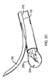
図1Aを参照すると、一実施形態において、本開示の組織生検システムは、それぞれの第1開口および第2開口115,117を画定する第1ワーキングチャネルおよび第2ワーキングチャネル114,116を含む長尺状部材110(例えばカテーテル、送達装置など)を備える。第1開口および第2開口115,117は、ほぼ円形および長円形にそれぞれ限定されず、様々な他の形状および/または形態を有してもよい。第1ワーキングチャネル114は、長尺状部材110の近位端部(図示せず)と遠位端部112との間に延びて、第1開口115を画定する。第2ワーキングチャネル116は、長尺状部材110の近位端部(図示せず)と外面113との間に延びて、第2開口117を画定する。第2ワーキングチャネル116は、長尺状部材110の遠位部分内で第2開口117において傾斜面118を画定する。傾斜面118は、長尺状部材110の長手軸線に対して約5度〜約10度の角度を備え、またそれらの間の任意の角度を備えてもよい。第2ワーキングチャネル116は、組織試料採取要素150(例えば生検針など)を摺動可能に受容するように構成されている。
Referring to FIG. 1A, in one embodiment, the tissue biopsy system of the present disclosure includes a first working channel and a second working channel 114,116 defining the first opening and the second opening 115, 117, respectively. A scale member 110 (for example, a catheter, a delivery device, etc.) is provided. The first opening and the second openings 115, 117 are not limited to substantially circular and oval, respectively, and may have various other shapes and / or forms. The
第1ワーキングチャネル114は、超音波振動子124がその遠位端部上に回転可能に配置された超音波プローブ120を受容するように構成されている。一実施形態において、超音波プローブ120は、第1ワーキングチャネル114内に固定して配置されていてもよい。別の実施形態では、超音波プローブ120は第1ワーキングチャネル内に摺動可能に配置されていてもよい。超音波振動子124を含む超音波プローブ120の遠位部分122は、長尺状部材110の第1開口115を通って、遠位端部112を越えて遠位に延びる。
The
エンドキャップ130は、超音波振動子124を包囲して保護するために、長尺状部材110の遠位端部112に取り付けられている。一実施形態において、エンドキャップ130は、通過する超音波エネルギーの減衰しない伝播を可能にするのに適当な厚さおよび屈折率を有する、高密度ポリエチレン(HDPE)を含むが、これに限定されないポリマー材料を含む。例えば、エンドキャップ130は、蛇行した狭い肺通路を通り抜けるために、非外傷性の端部(例えば円錐形、弾丸状の形状など)を備えた硬質プラスチック材料を含む。エンドキャップ130は、適当な溶着、はんだ付け、ろう付け、粘着剤、エポキシ、接着剤、および/または樹脂によって、長尺状部材110の遠位端部112に恒久的に取り付けられる。加えて、またはこれに代わって、エンドキャップ130は、スナップ嵌め、圧入(press fit)、締り嵌め(interference fit)および/または圧縮嵌合(compressive fit)のうちの少なくとも1つにより、長尺状部材110の遠位端部112に可逆的に取り付けられてもよい。エンドキャップ130は開放した(例えば中空の)内部空間を画定し、該内部空間は、医療処置の全過程を通じて塩水によって超音波プローブを洗い流す必要を排除する導電性物質140(例えばポリエチレングリコール(PEG)、ワセリン(petroleum gel)、カーボワックス、塩水など)で充填されている。エンドキャップ130が長尺状部材110に可逆的に取り付けられている実施形態では、エンドキャップは使用の直前に導電性物質で充填または再充填される。エンドキャップ130は、肺通路の組織壁との半径方向(例えば360度)の接触を提供するために、長尺状部材110の外径にほぼ等しい外径を有する。エンドキャップ130がより大きな肺通路の全内周と直接接触する能力は、超音波エネルギーが組織壁と接触する/組織壁を透過するのを阻止する/減衰させる空間(例えば空気)を除去することにより、向上した超音波画像を提供する。加えて、非外傷性の外形および低摩擦の外面により、組織生検システムがより狭い肺末梢に進められる際に、エンドキャップ130が組織との完全な周方向の接触を維持することが可能となる。図1Bを参照すると、組織試料採取要素150が、第2開口117を退出する際にエンドキャップ130と接触することなく、長尺状部材110の長手軸線から離れるように偏向する(例えば、屈曲する)ように、組織試料採取要素150は第2ワーキングチャネル116の傾斜面118に沿って遠位に進められる。
The
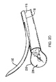
一実施形態において、図2Aを参照すると、長尺状部材110の遠位端部112は、通過する超音波エネルギーの減衰しない伝播を可能にするのに適当な厚さおよび屈折率を有する1つ以上のエラストマー材料および/またはコンプライアント材料を含むエンドキャップ230(例えば拡張可能部材、バルーンなど)を備える。セミコンプライアント材料としては、限定されない例として、ポリエステルエラストマー(例えばArnitel(登録商標)、Hytrel(登録商標)など)が挙げられる。コンプライアント材料としては、限定されない例として、ラテックスおよびシリコーンが挙げられる。当業者には理解されるように、コンプライアント材料から形成されたエンドキャップは無限に拡張することができる(例えば、一定の最終径を有さない)。例えば、これらの材料は、好ましくは10%〜800%の範囲、より好ましくは50%〜200%の範囲のコンプライアンスを有する。エンドキャップ230は、適当な粘着剤、エポキシ、接着剤および/または樹脂によって、長尺状部材110の遠位端部112に恒久的に取り付けられる。これに代わって、エンドキャップ230は、スナップ嵌め、圧入、締り嵌め、および/または圧縮嵌合のうちの少なくとも1つにより、長尺状部材110の遠位端部112に可逆的に取り付けられてもよい。エンドキャップ230は、外部流体源(図示せず)とエンドキャップの内部領域236との間に膨張流体(例えば塩水、ゲルなど)を流すことにより、第1形態(例えば、収縮した形態、予め膨張した形態など)と、1つ以上の第2形態(例えば、拡張した形態、膨張した形態など)との間を移行するように構成されている。一実施形態において、長尺状部材110は、近位端部(図示せず)と遠位端部112との間に延びて、外部流体源と内部領域236とを連通させる(in fluid communication)専用膨張流体送達管腔128を備える。これに代わって、膨張流体は、長尺状部材110の第1ワーキングチャネル114を通って超音波プローブ120のまわりの付随的空間内において外部流体源とエンドキャップ230の内部領域236との間を流れてもよい。
In one embodiment, referring to FIG. 2A, the
第1形態において、エンドキャップ230は、組織生検システムが医療装置(例えば気管支鏡など)のワーキングチャネルを通過し得るように縮小した外形(例えばより小さな直径)を提供するために、超音波プローブ120の遠位部分122のまわりに折り重なるか、または潰れている。加えて、エンドキャップ230の縮小した外形は、超音波プローブ120の遠位部分122に対して構造的支持を与えて、組織生検システムが肺通路を通って進められる際にキンキングおよび/または屈曲を防止する。
In the first embodiment, the
コンプライアント材料またはセミコンプライアント材料を有するエンドキャップは、エンドキャップ230が肺通路の特定の寸法に応じて第1形態(図2A)から様々な第2形態(図2B〜図2E)に移行することを可能にする。組織生検システムが可視化されるべき肺通路の一部の中に配置されると、エンドキャップ230の外面が肺通路の内周と直接接触して配置されるまで、膨張流体がエンドキャップ230の内部領域236に導入される。図2B〜図2Eは、エンドキャップ230がほぼ一様または対称な形態で拡張しているように示しているが、コンプライアント材料またはセミコンプライアント材料は、不規則または不均一な形状の身体通路(例えば分岐部など)との完全な接触を確立するために、エンドキャップ230が非対称的に拡張することを可能にしてもよい。エンドキャップ230の非外傷性の外形および低摩擦の外面により、組織生検システムがより狭い肺末梢内に進められる際に、組織との完全な周方向の接触が維持される。膨張流体は、医療処置の全体を通じて肺通路の組織壁との接触を維持するために必要に応じて、エンドキャップ230の内部領域236に導入されてもよいし、または内部領域236から除去されてもよい。エンドキャップ230の膨張の程度にかかわらず、組織試料採取要素150が、第2開口117を退出する際にエンドキャップ230と接触することなく、長尺状部材110の長手軸線から離れるように偏向する(例えば、屈曲する)ように、組織試料採取要素150は第2ワーキングチャネル116の傾斜面118に沿って遠位に進められる。
For end caps with compliant or semi-compliant material, the
別の実施形態では、エンドキャップ230は、第1形態から単一径/一定径の第2形態に移行するように構成された1つ以上のノンコンプライアント材料を含む。ノンコンプライアント材料としては、限定されない例として、ポリエチレンテレフタレート(PET)が挙げられる。コンプライアントまたはセミコンプライアント材料と比較して、ノンコンプライアント材料は、エンドキャップ230が第1形態にある場合に、超音波プローブ120の遠位部分122の構造的支持の増大をもたらす。ノンコンプライアント材料はまた、第2形態にある場合にも、構造的支持の増大をもたらして、例えば、肺通路の内周に及ぼされる力をより良好に制御し、かつ/または組織試料採取要素150との意図しない接触による穿通を阻止する。
In another embodiment, the
図3A〜図3Bを参照すると、別の実施形態において、本開示の組織生検システムは、超音波プローブ120の遠位部分122に取り付けられたコンプライアント、セミコンプライアント、またはノンコンプライアント材料を含むエンドキャップ330を備える。エンドキャップ330は、外部流体源(図示せず)とエンドキャップ330の内部領域336との間に膨張流体(例えば塩水など)を流すことにより、第1形態(図3A)と第2形態(図3B)との間を移行する。例えば、膨張流体は、超音波プローブ120に沿って、または超音波プローブ内を通って延びる専用流体送達管腔(図示せず)を通って、外部流体源とエンドキャップ330の内部領域336との間を流れる。これに代わって、エンドキャップ330は、膨張流体が長尺状部材110の第1ワーキングチャネル114を通って超音波プローブ120のまわりの付随的空間内において外部流体源とエンドキャップ330の内部領域336との間を流れ得るように、第1開口115のまわりで長尺状管状部材110の遠位端部112に取り付けられてもよい。第1形態では、エンドキャップ330は、組織生検システムが医療装置(例えば気管支鏡など)のワーキングチャネルを通過し得るように縮小した外形(例えばより小さな直径)を提供するために、超音波プローブ120の遠位部分122のまわりに折り重なっているか、または潰れている。加えて、エンドキャップ330は、超音波プローブ120の遠位部分122に対して構造的支持を与えて、組織生検システムが肺通路を通って進められる際にキンキングおよび/または屈曲を防止する。
Referring to FIGS. 3A-3B, in another embodiment, the tissue biopsy system of the present disclosure comprises a compliant, semi-compliant, or non-compliant material attached to the
医療専門家が可視化を望む肺通路の一部の中に組織生検システムが配置されると、エンドキャップの外面が肺通路の内周と直接接触して配置されるまで、膨張流体はエンドキャップ330の内部領域336に導入される。上記のように、コンプライアントまたはセミコンプライアント材料を含むエンドキャップ330は、不規則または不均一な形状の身体通路との完全接触を確立するために非対称に拡張してもよい。エンドキャップ330の非外傷性の外形および低摩擦の外面により、組織生検システムがより狭い肺末梢内に進められる際に、組織との完全な周方向の接触が維持される。膨張流体は、医療処置の全体を通じて肺通路の組織壁との接触を維持するために必要に応じて、エンドキャップ330の内部領域336に導入されてもよいし、または内部領域336から除去されてもよい。エンドキャップの膨張の程度にかかわらず、組織試料採取要素150が、第2開口117を退出する際にエンドキャップ330と接触することなく、長尺状部材110の長手軸線から離れるように偏向する(例えば、屈曲する)ように、組織試料採取要素150は第2ワーキングチャネル116の傾斜面118に沿って遠位に進められる。
When the tissue biopsy system is placed in the part of the lung passage that medical professionals want to visualize, the expanding fluid is placed in the end cap until the outer surface of the end cap is placed in direct contact with the inner circumference of the lung passage. It is introduced into the
図4A〜図4Bを参照すると、一実施形態において、本開示の組織生検システムは、超音波プローブ120の遠位部分122に取り付けられた2つ以上の(コンプライアント、セミコンプライアント、またはノンコンプライアント)エンドキャップ430を備える。エンドキャップ430は、第1形態(図4A)にある場合に、図3Aの形態のような単一のエンドキャップと比較して、超音波プローブ120の遠位部分122にさらなる構造的支持を与える。加えて、エンドキャップ430の各々は、不規則または不均一な形状の身体通路との完全な周方向の接触を維持するために必要に応じて各エンドキャップが第1形態と第2形態との間を独立して移行することができるように別個の/専用の流体送達管腔(図示せず)を備える。例えば、膨張流体は、超音波プローブ120に沿って、または超音波プローブ内を通って延びる別個の専用流体送達管腔(図示せず)を通って、外部流体源とエンドキャップ430の内部領域との間を流れる。
Referring to FIGS. 4A-4B, in one embodiment, the tissue biopsy system of the present disclosure is two or more (compliant, semi-compliant, or non-compliant) attached to the
使用時に、例として、本願において開示する生検システムは、エンドキャップ130,230,330,430が身体通路の組織壁と半径方向(例えば360度)に接触して配置されるように、身体通路(例えば肺末梢)内に進められる。組織壁内または組織壁に隣接した標的組織の識別に際して、組織試料採取要素150がエンドキャップ130,230,330,430と接触することなく、長尺状部材110の長手軸線から離れて標的組織内へと偏向する(例えば、屈曲する)ように、組織試料採取要素150は第2ワーキングチャネル116の傾斜面118に沿って遠位に進められる。生検システムは次に身体通路から抜去され、標的組織採取要素150の管腔内に捕捉された標的組織は分析のために取り出される。これに代わって、組織試料採取要素150は第2ワーキングチャネル116の傾斜面118に沿って近位に後退させられてもよく、生検システムは身体通路を通って1つ以上のさらなる標的組織部位に進められ、組織試料採取要素150は分析のためのさらなる標的組織を捕捉するために遠位に進められる。
In use, as an example, the biopsy system disclosed herein is arranged such that the end caps 130, 230, 330, 430 are placed in radial contact (eg, 360 degrees) with the tissue wall of the body passage. It is advanced within (eg, peripheral lung). In identifying the target tissue within or adjacent to the tissue wall, the
本開示のエンドキャップについて図1A〜図4Bに示した特定の実施形態に関して説明してきたが、様々な実施形態において、開示した組織生検システムは、長尺状部材110の遠位端部112または超音波プローブ120の遠位部分122に対称的または非対称的に取り付けられた、いかなる数のコンプライアント、セミコンプライアントまたはノンコンプライアントエンドキャップを備えてもよい。開示したエンドキャップ230,330,430のうちのいずれかのようなエンドキャップの内面または外面は、エンドキャップが肺通路を過剰拡張させて肺通路の膨満を引き起こさないことを保証するために、1つ以上の圧力センサーを備えてもよい。同様に、図1A〜図1Bのエンドキャップ130は、組織生検システムが肺末梢内に進められる際に、組織壁に対して過度の力が及ぼされないことを保証するために、1つ以上の圧力センサーを備えてもよい。肺通路の向上した可視化を提供することに加えて、開示したエンドキャップ形態130,230,330,430のうちのいずれも、組織試料採取要素が作動される際に長手方向および/または回転方向の移動を最小限にするように、身体通路内において組織生検システムを固定すること、および/または動かなくすることによって、組織試料採取要素が標的組織を逃す可能性を低減することにより、さらなる便益を与える。開示したエンドキャップ形態のいずれかのさらなる利点は、組織試料採取要素によるより精密/正確な生検のために、標的組織が少なくとも部分的に動かなくされるように、標的組織に隣接した肺通路の一部に張力がかかるようにすることができることである。
Although the end caps of the present disclosure have been described for the particular embodiments shown in FIGS. 1A-4B, in various embodiments the disclosed tissue biopsy system is the
本開示の医療装置は、気管支鏡に限定されず、例えば、カテーテル、尿管鏡、十二指腸内視鏡、結腸内視鏡、関節鏡、膀胱鏡、子宮鏡などを含む身体通路にアクセスするための様々な医療装置を含み得る。最後に、本開示の実施形態は気管支鏡との使用について記載されているが、本開示の組織生検システムは、付随する医療装置が不在の状態で患者内に配置されてもよい。 The medical devices of the present disclosure are not limited to bronchoscopes, but for accessing body passages including, for example, catheters, ureteroscopes, duodenal endoscopes, colon endoscopes, arthroscopy, cystoscopes, hystoscopes and the like. It may include various medical devices. Finally, although embodiments of the present disclosure describe use with a bronchoscope, the tissue biopsy system of the present disclosure may be placed within the patient in the absence of associated medical equipment.
本願において開示し権利請求する装置および/または方法はすべて、本開示を踏まえて、過度の実験作業を行うことなく、製造および実施することができる。この開示の装置および方法は好ましい実施形態に関して説明されているが、本開示の概念、趣旨および範囲から逸脱することなく、本願に記載した装置および/または方法に対して、ならびにそれらの方法のステップまたはステップの順序において、変形例を適用できることは当業者には明らかである。当業者には明らかなそのような類似した代替物および変更例はすべて、添付する特許請求の範囲によって定義される本開示の趣旨、範囲および概念の内にあると考えられる。 All of the devices and / or methods disclosed and claimed in the present application can be manufactured and implemented in light of this disclosure without undue experimental work. Although the devices and methods of this disclosure have been described for preferred embodiments, with respect to the devices and / or methods described herein, and in steps of those methods, without departing from the concepts, intent and scope of the present disclosure. Alternatively, it will be apparent to those skilled in the art that variations can be applied in the order of the steps. All such similar alternatives and modifications apparent to those skilled in the art are believed to be within the spirit, scope and concept of the present disclosure as defined by the appended claims.
Claims (14)
第1ワーキングチャネル内に配置された超音波プローブであって、該超音波プローブの遠位部分は前記長尺状部材の遠位端部を越えて遠位に延在可能である、超音波プローブと、
前記超音波プローブが第1開口の外側に延在するときに前記超音波プローブの遠位部分を包囲するように、前記長尺状部材の遠位端部に取り付けられたエンドキャップと、を備えており、
前記エンドキャップが導電性物質によって充填可能である、システム。 An elongated member containing a first working channel and a second working channel defining the first and second openings, respectively.
An ultrasonic probe disposed within a first working channel, wherein the distal portion of the ultrasonic probe can extend distally beyond the distal end of the elongated member. When,
An end cap attached to the distal end of the elongated member is provided so as to surround the distal portion of the ultrasonic probe when it extends outside the first opening. And
It said end cap Ru der fillable with a conductive material, the system.
第1ワーキングチャネル内に配置された超音波プローブであって、該超音波プローブの遠位部分は前記長尺状部材の遠位端部を越えて遠位に延在可能である、超音波プローブと、
前記超音波プローブの遠位部分に取り付けられたエンドキャップと、
を備えており、
前記エンドキャップが導電性物質によって充填可能である、システム。 An elongated member containing a first working channel and a second working channel defining the first and second openings, respectively.
An ultrasonic probe disposed within a first working channel, wherein the distal portion of the ultrasonic probe can extend distally beyond the distal end of the elongated member. When,
With an end cap attached to the distal part of the ultrasonic probe,
Equipped with a,
A system in which the end cap can be filled with a conductive material .
Applications Claiming Priority (3)
| Application Number | Priority Date | Filing Date | Title |
|---|---|---|---|
| US201762464166P | 2017-02-27 | 2017-02-27 | |
| US62/464,166 | 2017-02-27 | ||
| PCT/US2018/019669 WO2018157038A1 (en) | 2017-02-27 | 2018-02-26 | Systems for body passage navigation and visualization |
Related Child Applications (1)
| Application Number | Title | Priority Date | Filing Date |
|---|---|---|---|
| JP2020188535A Division JP7196144B2 (en) | 2017-02-27 | 2020-11-12 | System for navigation and visualization of body passages |
Publications (2)
| Publication Number | Publication Date |
|---|---|
| JP2020503116A JP2020503116A (en) | 2020-01-30 |
| JP6795701B2 true JP6795701B2 (en) | 2020-12-02 |
Family
ID=61750515
Family Applications (3)
| Application Number | Title | Priority Date | Filing Date |
|---|---|---|---|
| JP2019534752A Active JP6795701B2 (en) | 2017-02-27 | 2018-02-26 | System for navigation and visualization of body passages |
| JP2020188535A Active JP7196144B2 (en) | 2017-02-27 | 2020-11-12 | System for navigation and visualization of body passages |
| JP2022199251A Pending JP2023021302A (en) | 2017-02-27 | 2022-12-14 | Systems for body passage navigation and visualization |
Family Applications After (2)
| Application Number | Title | Priority Date | Filing Date |
|---|---|---|---|
| JP2020188535A Active JP7196144B2 (en) | 2017-02-27 | 2020-11-12 | System for navigation and visualization of body passages |
| JP2022199251A Pending JP2023021302A (en) | 2017-02-27 | 2022-12-14 | Systems for body passage navigation and visualization |
Country Status (8)
| Country | Link |
|---|---|
| US (2) | US11202617B2 (en) |
| EP (1) | EP3585270A1 (en) |
| JP (3) | JP6795701B2 (en) |
| KR (3) | KR20230154284A (en) |
| CN (2) | CN110325121B (en) |
| AU (1) | AU2018224224B2 (en) |
| CA (1) | CA3046556C (en) |
| WO (1) | WO2018157038A1 (en) |
Families Citing this family (7)
| Publication number | Priority date | Publication date | Assignee | Title |
|---|---|---|---|---|
| JPWO2020079762A1 (en) * | 2018-10-16 | 2021-09-02 | オリンパス株式会社 | How to use guide tube, ultrasonic probe, ultrasonic observation system, and ultrasonic observation system |
| WO2020236595A1 (en) * | 2019-05-17 | 2020-11-26 | Boston Scientific Scimed, Inc. | Apparatus to provide an adjustable mechanism for radial ultrasound port and flush port |
| US11564655B2 (en) * | 2019-07-03 | 2023-01-31 | Olympus Medical Systems Corporation | Real-time sampling device |
| CN110292403A (en) * | 2019-07-04 | 2019-10-01 | 南京市胸科医院 | A kind of device and method of bronchus supersonic sounding and biopsy synchronized sampling |
| WO2022000533A1 (en) * | 2020-07-02 | 2022-01-06 | 江苏钱璟医疗器械有限公司 | Multi-lumen tube and endoscope assembly |
| WO2022229947A1 (en) * | 2021-04-25 | 2022-11-03 | V.T.M. (Virtual Tape Measure) Technologies Ltd. | A distal end of a probe configured for passing through a working channel in an endoscopic device |
| CN116898385A (en) * | 2023-07-04 | 2023-10-20 | 北京大学 | Insertion instrument and endoscope |
Family Cites Families (27)
| Publication number | Priority date | Publication date | Assignee | Title |
|---|---|---|---|---|
| JP2706145B2 (en) * | 1989-05-12 | 1998-01-28 | オリンパス光学工業株式会社 | Ultrasound probe for body cavity diagnosis |
| JPH0663042A (en) * | 1992-08-20 | 1994-03-08 | Olympus Optical Co Ltd | Intra-celom ultrasonic probe device |
| JPH0663045A (en) * | 1992-08-20 | 1994-03-08 | Olympus Optical Co Ltd | Ultrasonic endoscope |
| JPH0663042U (en) | 1993-02-12 | 1994-09-06 | 時之助 池田 | Medication alarm |
| JPH07136169A (en) * | 1993-11-10 | 1995-05-30 | Fuji Photo Optical Co Ltd | Ultrasonic probe |
| US5474075A (en) * | 1993-11-24 | 1995-12-12 | Thomas Jefferson University | Brush-tipped catheter for ultrasound imaging |
| JP2891086B2 (en) * | 1994-01-07 | 1999-05-17 | 富士写真光機株式会社 | Treatment instrument insertion passage for in-vivo examination device |
| JPH08131442A (en) * | 1994-11-04 | 1996-05-28 | Olympus Optical Co Ltd | Ultrasonic endoscope |
| JP3543027B2 (en) | 1995-04-10 | 2004-07-14 | オリンパス株式会社 | Curved sheath for probe |
| JP3092479B2 (en) * | 1995-05-31 | 2000-09-25 | 富士写真光機株式会社 | Ultrasonic probe cap |
| JPH10216133A (en) * | 1997-02-10 | 1998-08-18 | Olympus Optical Co Ltd | Ultrasonic probe |
| JP4363719B2 (en) * | 1999-10-08 | 2009-11-11 | オリンパス株式会社 | Ultrasound-guided puncture system device |
| JP2003164455A (en) | 2001-11-30 | 2003-06-10 | Olympus Optical Co Ltd | Ultrasonic endoscope and bronchus tube therefor |
| JP2003299657A (en) * | 2002-04-11 | 2003-10-21 | Olympus Optical Co Ltd | Ultrasonic diagnostic equipment |
| JP2006198162A (en) * | 2005-01-20 | 2006-08-03 | Fuji Photo Film Co Ltd | Ultrasonic probe |
| US20080015569A1 (en) * | 2005-02-02 | 2008-01-17 | Voyage Medical, Inc. | Methods and apparatus for treatment of atrial fibrillation |
| US20080004528A1 (en) * | 2006-01-25 | 2008-01-03 | Fitzsimons Thomas P | Ultrasound medical system and methods |
| US8016749B2 (en) | 2006-03-21 | 2011-09-13 | Boston Scientific Scimed, Inc. | Vision catheter having electromechanical navigation |
| JP2009543607A (en) * | 2006-07-10 | 2009-12-10 | ボエッジ メディカル, インコーポレイテッド | Method and apparatus for the treatment of atrial fibrillation |
| JP5322761B2 (en) * | 2009-04-28 | 2013-10-23 | オリンパス株式会社 | Endoscope adapter |
| US9642513B2 (en) * | 2009-06-18 | 2017-05-09 | Endochoice Inc. | Compact multi-viewing element endoscope system |
| JP5285649B2 (en) * | 2010-03-31 | 2013-09-11 | 富士フイルム株式会社 | Endoscope hood |
| US20130225996A1 (en) | 2012-02-28 | 2013-08-29 | Spiration, Inc. | Lung biopsy needle |
| US9295455B2 (en) | 2012-04-20 | 2016-03-29 | Terumo Kabushiki Kaisha | Biopsy system and biopsy method |
| KR102057322B1 (en) * | 2013-03-15 | 2019-12-19 | 데비코어 메디컬 프로덕츠, 인코포레이티드 | Biopsy device |
| WO2015153931A1 (en) * | 2014-04-02 | 2015-10-08 | The Board Of Trustees Of The Leland Stanford Jr. University | Biopsy devices, systems, and methods for use |
| US11234581B2 (en) * | 2014-05-02 | 2022-02-01 | Endochoice, Inc. | Elevator for directing medical tool |
-
2018
- 2018-02-26 CN CN201880013438.XA patent/CN110325121B/en active Active
- 2018-02-26 CA CA3046556A patent/CA3046556C/en active Active
- 2018-02-26 AU AU2018224224A patent/AU2018224224B2/en active Active
- 2018-02-26 EP EP18712742.8A patent/EP3585270A1/en active Pending
- 2018-02-26 WO PCT/US2018/019669 patent/WO2018157038A1/en unknown
- 2018-02-26 KR KR1020237036989A patent/KR20230154284A/en not_active Application Discontinuation
- 2018-02-26 CN CN202210318557.4A patent/CN114869353A/en active Pending
- 2018-02-26 US US15/904,846 patent/US11202617B2/en active Active
- 2018-02-26 KR KR1020227012022A patent/KR20220056245A/en not_active IP Right Cessation
- 2018-02-26 JP JP2019534752A patent/JP6795701B2/en active Active
- 2018-02-26 KR KR1020197027734A patent/KR102431658B1/en active IP Right Grant
-
2020
- 2020-11-12 JP JP2020188535A patent/JP7196144B2/en active Active
-
2021
- 2021-12-14 US US17/550,414 patent/US20220096050A1/en active Pending
-
2022
- 2022-12-14 JP JP2022199251A patent/JP2023021302A/en active Pending
Also Published As
| Publication number | Publication date |
|---|---|
| CA3046556A1 (en) | 2018-08-30 |
| CA3046556C (en) | 2021-10-12 |
| CN110325121A (en) | 2019-10-11 |
| JP2021035570A (en) | 2021-03-04 |
| KR102431658B1 (en) | 2022-08-11 |
| US20180242948A1 (en) | 2018-08-30 |
| AU2018224224A1 (en) | 2019-06-13 |
| AU2018224224B2 (en) | 2020-05-21 |
| JP7196144B2 (en) | 2022-12-26 |
| KR20220056245A (en) | 2022-05-04 |
| JP2020503116A (en) | 2020-01-30 |
| US20220096050A1 (en) | 2022-03-31 |
| JP2023021302A (en) | 2023-02-10 |
| US11202617B2 (en) | 2021-12-21 |
| WO2018157038A1 (en) | 2018-08-30 |
| EP3585270A1 (en) | 2020-01-01 |
| KR20190121807A (en) | 2019-10-28 |
| CN114869353A (en) | 2022-08-09 |
| KR20230154284A (en) | 2023-11-07 |
| CN110325121B (en) | 2022-04-19 |
Similar Documents
| Publication | Publication Date | Title |
|---|---|---|
| JP6795701B2 (en) | System for navigation and visualization of body passages | |
| US20210000495A1 (en) | Clot evacuation and visualization devices and methods of use | |
| JP6707097B2 (en) | Optical coupler for endoscope | |
| US5025778A (en) | Endoscope with potential channels and method of using the same | |
| US11622753B2 (en) | Fully integrated endoscope with biopsy capabilities and methods of use | |
| JP5111112B2 (en) | Device for performing needle-guided therapy | |
| JP5489418B2 (en) | Ultrasonic probe hood and ultrasonic probe | |
| US20150080764A1 (en) | Disposable instrument including working channels for endoscopy | |
| JP2010510029A (en) | Device for passage creation and blood vessel sensing | |
| US8622957B2 (en) | Adjustable variable stiffness transluminal device | |
| JP2018520760A (en) | Endoscope sheath | |
| JP2009240658A (en) | Balloon for ultrasonic probe and ultrasonic endoscope | |
| JP6203451B1 (en) | Ultrasound endoscope | |
| JP7389775B2 (en) | endoscope tip extender | |
| JP7015782B2 (en) | Sheath for needle delivery |
Legal Events
| Date | Code | Title | Description |
|---|---|---|---|
| A621 | Written request for application examination |
Free format text: JAPANESE INTERMEDIATE CODE: A621 Effective date: 20190624 |
|
| A977 | Report on retrieval |
Free format text: JAPANESE INTERMEDIATE CODE: A971007 Effective date: 20200529 |
|
| A131 | Notification of reasons for refusal |
Free format text: JAPANESE INTERMEDIATE CODE: A131 Effective date: 20200616 |
|
| A521 | Request for written amendment filed |
Free format text: JAPANESE INTERMEDIATE CODE: A523 Effective date: 20200914 |
|
| TRDD | Decision of grant or rejection written | ||
| A01 | Written decision to grant a patent or to grant a registration (utility model) |
Free format text: JAPANESE INTERMEDIATE CODE: A01 Effective date: 20201013 |
|
| A61 | First payment of annual fees (during grant procedure) |
Free format text: JAPANESE INTERMEDIATE CODE: A61 Effective date: 20201112 |
|
| R150 | Certificate of patent or registration of utility model |
Ref document number: 6795701 Country of ref document: JP Free format text: JAPANESE INTERMEDIATE CODE: R150 |
|
| R250 | Receipt of annual fees |
Free format text: JAPANESE INTERMEDIATE CODE: R250 |