JP6795269B2 - Aerosol generator and aerosol generator control method and program - Google Patents
Aerosol generator and aerosol generator control method and program Download PDFInfo
- Publication number
- JP6795269B2 JP6795269B2 JP2019237785A JP2019237785A JP6795269B2 JP 6795269 B2 JP6795269 B2 JP 6795269B2 JP 2019237785 A JP2019237785 A JP 2019237785A JP 2019237785 A JP2019237785 A JP 2019237785A JP 6795269 B2 JP6795269 B2 JP 6795269B2
- Authority
- JP
- Japan
- Prior art keywords
- power supply
- condition
- value
- control unit
- measured value
- Prior art date
- Legal status (The legal status is an assumption and is not a legal conclusion. Google has not performed a legal analysis and makes no representation as to the accuracy of the status listed.)
- Active
Links
Images


Description
本開示は、ユーザが吸引するエアロゾル又は香味が付与されたエアロゾルを生成する装置並びにそのようなエアロゾル生成装置の制御方法及びプログラムに関する。 The present disclosure relates to an aerosol that is sucked by a user or an aerosol that is flavored with an aerosol, and a control method and program for such an aerosol generator.
これまで電子シガレットのヒータの近傍にエアロゾル源を保持する役割を果たすウィックとして、ガラス繊維が広く用いられてきた。ところで、製造工程の簡素化やエアロゾル生成量の向上が期待できるため、ガラス繊維に代えてセラミックをウィックへ用いることが検討されている。 So far, glass fiber has been widely used as a wick that holds an aerosol source near the heater of an electronic cigarette. By the way, since it is expected that the manufacturing process will be simplified and the amount of aerosol produced will be improved, the use of ceramic for the wick instead of the glass fiber is being studied.
ガラス繊維をウィックに用いた電子シガレットでは、吸引を開始したら即時にヒータがエアロゾル源を霧化することによって生成されたエアロゾルがユーザの口腔内に送達され、吸引を停止したら即時にこのエアロゾルの生成を停止するという、ユーザの吸引に対して違和感が無いような制御を行っている。セラミック、例えばアルミナ製のウィックを使用する場合、典型的なアルミナ製ウィックの熱容量は0.008J/K程度と、典型的なガラス繊維製ウィックの熱容量0.003J/K程度と比べて高いため、これまでと同様の感覚で電子シガレットでの喫煙を楽しめるようにするためには、1つのパフ(吸引サイクル)において、ヒータへの通電を開始するタイミングと、終了するタイミングとを早める必要がある。 In an electronic cigarette using glass fiber as a wick, the aerosol produced by the heater atomizing the aerosol source immediately after starting suction is delivered into the user's oral cavity, and this aerosol is generated immediately when suction is stopped. It is controlled so that there is no sense of discomfort with the user's suction by stopping. When a ceramic, for example, an alumina wick is used, the heat capacity of a typical alumina wick is about 0.008 J / K, which is higher than the heat capacity of a typical glass fiber wick of about 0.003 J / K. In order to enjoy smoking with an electronic cigarette with the same feeling as before, it is necessary to accelerate the timing of starting and ending the energization of the heater in one puff (suction cycle).
これに関し、パフ始期を判定する閾値を、終期を判定する閾値より小さくする技術が提案されている(例えば、特許文献1)。
しかしながら、パフ始期を判定する閾値を小さくした場合、ノイズを拾いやすくなり、結果として無用な通電が起きやすいという問題があった。
In this regard, a technique has been proposed in which the threshold value for determining the beginning of the puff is made smaller than the threshold value for determining the end of the puff (for example, Patent Document 1).
However, when the threshold value for determining the start of the puff is reduced, there is a problem that noise is easily picked up, and as a result, unnecessary energization is likely to occur.
また、パフ終期を判定する閾値を、パフ始期を判定する閾値より大きくした場合、信号と閾値との大小比較のみを用いた判定では、パフ開始の条件を充足したタイミングと略同時に又は直後に、パフ終了の条件を充足してしまうという問題があった。 In addition, when the threshold value for determining the puff end is made larger than the threshold for determining the puff start, in the determination using only the magnitude comparison between the signal and the threshold value, approximately at the same time as or immediately after the timing when the puff start condition is satisfied, There was a problem that the condition for ending the puff was satisfied.
更に、判定に係る閾値として適切な値は、吸引の仕方により異なり且つこの吸引の仕方には個人差があるという問題があった。 Further, there is a problem that an appropriate value as a threshold value for determination differs depending on the suction method and there are individual differences in this suction method.
本開示は、以上に鑑みてなされたものである。
本開示が解決しようとする第1の課題は、無用な通電を抑制しつつ適切なタイミングでエアロゾルを生成できるエアロゾル生成装置を提供することである。
The present disclosure has been made in view of the above.
The first problem to be solved by the present disclosure is to provide an aerosol generator capable of generating an aerosol at an appropriate timing while suppressing unnecessary energization.
本開示が解決しようとする第2の課題は、適切なタイミングでエアロゾル生成を停止できるエアロゾル生成装置を提供することである。
本開示が解決しようとする第3の課題は、エアロゾル生成を停止するタイミングをユーザ毎に最適化できるエアロゾル生成装置を提供することである。
A second problem to be solved by the present disclosure is to provide an aerosol generator capable of stopping aerosol generation at an appropriate timing.
A third problem to be solved by the present disclosure is to provide an aerosol generation apparatus capable of optimizing the timing at which aerosol generation is stopped for each user.
上述した第1の課題を解決するため、本開示の第1実施形態によれば、エアロゾル源の霧化及び香味源の加熱の一方又は双方を行うために給電する電源と、前記給電を制御するための測定値を出力するセンサと、前記測定値に基づき、前記給電を制御する制御部とを含み、前記制御部は、前記測定値が第1閾値以上且つ該第1閾値より大きい第2閾値未満の場合、前記電源の給電量を第1の値とし、前記測定値が前記第2閾値以上の場合、前記給電量を前記第1の値より大きくするように制御する、エアロゾル生成装置が提供される。 In order to solve the first problem described above, according to the first embodiment of the present disclosure, the power supply to be supplied to perform one or both of atomization of the aerosol source and heating of the flavor source, and the power supply are controlled. The control unit includes a sensor that outputs a measured value for the purpose and a control unit that controls the power supply based on the measured value, and the control unit has a second threshold value whose measured value is equal to or higher than the first threshold value and larger than the first threshold value. Provided by an aerosol generator that controls the power supply amount to be larger than the first value when the measured value is equal to or greater than the second threshold value and the power supply amount of the power supply is set to the first value. Will be done.
一実施形態において、前記第1の値の給電量により、前記エアロゾル源又は香味源からエアロゾルは生成されない。
一実施形態において、前記制御部は、前記測定値が前記第1閾値以上になってから又は前記第1の値の給電の開始から、既定時間内に前記第2閾値以上にならない場合、給電を停止する。
In one embodiment, the first value of the feed amount does not produce an aerosol from the aerosol source or flavor source.
In one embodiment, the control unit supplies power when the measured value does not reach the second threshold or higher within a predetermined time after the measured value becomes equal to or higher than the first threshold value or from the start of feeding the first value. Stop.
一実施形態において、前記第1の値の給電量を与えるための電力又は単位時間当たりの電力量と前記既定時間の少なくとも一方は、前記第1の値が、前記エアロゾル源又は前記香味源から、エアロゾルの生成が開始される給電量以下になるように設定される。 In one embodiment, at least one of the electric energy or electric energy per unit time for providing the power supply amount of the first value and the predetermined time is such that the first value is from the aerosol source or the flavor source. It is set so that it is less than or equal to the power supply amount at which aerosol generation is started.
一実施形態において、前記測定値が前記第1閾値以上且つ前記第2閾値未満の場合の単位時間当たりの給電量は、0値と、前記測定値が前記第2閾値以上の場合の単位時間当たりの給電量との間にあり、且つ、前者より後者に近い。 In one embodiment, the amount of power supplied per unit time when the measured value is equal to or greater than the first threshold value and less than the second threshold value is 0 and per unit time when the measured value is equal to or greater than the second threshold value. It is between the power supply amount of and closer to the latter than the former.
一実施形態において、前記制御部は、前記測定値が前記第2閾値以上の前記第3閾値を下回った場合、給電を停止する。
一実施形態において、前記第2閾値は、前記第3閾値より前記第1閾値に近い。
In one embodiment, the control unit stops power supply when the measured value falls below the third threshold value equal to or higher than the second threshold value.
In one embodiment, the second threshold is closer to the first threshold than the third threshold.
一実施形態において、前記第2閾値は、前記第1閾値より前記第3閾値に近い。
一実施形態において、前記第2閾値は、前記第3閾値と等しい。
一実施形態において、前記第2閾値と前記第1閾値の差分は、前記第1閾値より大きい。
In one embodiment, the second threshold is closer to the third threshold than the first threshold.
In one embodiment, the second threshold is equal to the third threshold.
In one embodiment, the difference between the second threshold and the first threshold is greater than the first threshold.
一実施形態において、前記エアロゾル源及び前記香味源の一方又は双方をある位置へ輸送すること及び該位置で保持することの一方又は双方を、内部に備えた細孔により行う多孔質体を含み、前記位置は、前記電源からの給電で動作する負荷が霧化及び加熱の一方又は双方を可能な位置である。 In one embodiment, it comprises a porous body in which one or both of the aerosol source and the flavor source are transported to a certain position and one or both of the flavor sources are held at the position by means of pores provided inside. The position is a position where the load operated by the power supply from the power source can perform one or both of atomization and heating.
また、本開示の第1実施形態によれば、センサから出力された測定値に基づき、エアロゾル源の霧化及び香味源の加熱の一方又は双方を行うために電源の給電を制御するためのエアロゾル生成装置の制御方法であって、前記測定値が第1閾値以上且つ該第1閾値より大きい第2閾値未満の場合、前記電源の給電量を第1の値とするステップと、前記測定値が前記第2閾値以上の場合、前記給電量を前記第1の値より大きくするステップとを含むエアロゾル生成装置の制御方法が提供される。 Further, according to the first embodiment of the present disclosure, based on the measured value output from the sensor, the aerosol for controlling the power supply to perform one or both of atomization of the aerosol source and heating of the flavor source. In the control method of the generator, when the measured value is equal to or more than the first threshold value and less than the second threshold value larger than the first threshold value, the step of setting the power supply amount of the power supply to the first value and the measured value are In the case of the second threshold value or more, a control method of the aerosol generation device including the step of increasing the feed amount to be larger than the first value is provided.
また、本開示の第1実施形態によれば、プロセッサに、上記の制御方法を実行させるためのプログラムが提供される。
また、本開示の第1実施形態によれば、エアロゾル源の霧化及び香味源の加熱の一方又は双方を行うために給電する電源と、前記給電を制御するための測定値を出力するセンサと、前記測定値に基づき、前記給電を制御する制御部とを含み、前記制御部は、前記測定値が第1閾値以上且つ該第1閾値より大きい第2閾値未満の場合、前記電源から第1電力を給電させ、前記測定値が前記第2閾値以上の場合、前記電源から前記第1電力より大きい電力を給電させるように制御する、エアロゾル生成装置が提供される。
Further, according to the first embodiment of the present disclosure, a program for causing the processor to execute the above control method is provided.
Further, according to the first embodiment of the present disclosure, a power supply that supplies power to perform one or both of atomization of the aerosol source and heating of the flavor source, and a sensor that outputs a measured value for controlling the power supply. The control unit includes a control unit that controls the power supply based on the measured value, and the control unit is the first from the power source when the measured value is equal to or more than the first threshold value and less than the second threshold value larger than the first threshold value. Provided is an aerosol generator that supplies power and controls the power supply to supply power larger than the first power when the measured value is equal to or higher than the second threshold value.
また、本開示の第1実施形態によれば、エアロゾル源の霧化及び香味源の加熱の一方又は双方を行うために給電する電源と、前記給電を制御するための測定値を出力するセンサと、前記測定値に基づき、前記給電を制御する制御部とを含み、前記制御部は、前記測定値が第1閾値を越えた場合、前記電源の給電量を第2の値とし、前記電源が前記第2の値を給電した後に、前記測定値が前記第1閾値より大きい第2閾値を下回った場合、前記給電を停止し、前記測定値が前記第1閾値を越える前の前記給電量を前記第2の値より小さくするように制御する、エアロゾル生成装置が提供される。 Further, according to the first embodiment of the present disclosure, a power supply that supplies power to perform one or both of atomization of the aerosol source and heating of the flavor source, and a sensor that outputs a measured value for controlling the power supply. The control unit includes a control unit that controls the power supply based on the measured value, and when the measured value exceeds the first threshold value, the control unit sets the power supply amount of the power supply as a second value, and the power supply causes the power supply. When the measured value falls below the second threshold value larger than the first threshold value after the second value is fed, the power supply is stopped and the power supply amount before the measured value exceeds the first threshold value is applied. Provided is an aerosol generator that is controlled to be smaller than the second value.
また、上述した第2の課題を解決するため、本開示の第2実施形態によれば、エアロゾル源の霧化及び香味源の加熱の一方又は双方を行うために給電する電源と、前記給電を制御するための測定値を出力するセンサと、前記測定値に基づき、前記電源の給電を制御する制御部とを含み、前記制御部は、前記測定値が第1閾値以上という第1条件を満たす場合に、単位時間当たりの給電量(以下、「単位給電量」という。)を増加させ、前記測定値が前記第1閾値より大きい第2閾値未満という第2条件及び前記第1条件と前記第2条件とは異なる第3条件を満たす場合に、前記単位給電量を減少させるように制御する、エアロゾル生成装置が提供される。 Further, in order to solve the above-mentioned second problem, according to the second embodiment of the present disclosure, a power supply that supplies power to perform one or both of atomization of the aerosol source and heating of the flavor source, and the power supply are supplied. The control unit includes a sensor that outputs a measured value for control and a control unit that controls power supply of the power supply based on the measured value, and the control unit satisfies the first condition that the measured value is equal to or higher than the first threshold value. In this case, the second condition that the amount of power supplied per unit time (hereinafter referred to as "unit power supply amount") is increased and the measured value is larger than the first threshold value and less than the second threshold value, and the first condition and the first condition. Provided is an aerosol generator that controls so as to reduce the unit feed amount when a third condition different from the two conditions is satisfied.
一実施形態において、前記第3条件は、前記第1条件と同時に満たされない。
一実施形態において、前記第2条件は、前記第3条件より先に満たすことが可能である。
In one embodiment, the third condition is not met at the same time as the first condition.
In one embodiment, the second condition can be met before the third condition.
一実施形態において、前記第3条件は、前記測定値に基づく条件である。
一実施形態において、前記第3条件は、前記測定値の時間微分に基づく条件である。
一実施形態において、前記第3条件は、前記測定値の時間微分が0以下であるという条件である。
In one embodiment, the third condition is a condition based on the measured value.
In one embodiment, the third condition is a condition based on the time derivative of the measured value.
In one embodiment, the third condition is that the time derivative of the measured value is 0 or less.
一実施形態において、前記第3条件は、前記測定値の時間微分が0より小さい第3閾値以下であるという条件である。
一実施形態において、前記制御部は、前記第2条件及び前記第3条件が満たされてから、既定の復帰期間内に前記測定値の時間微分が0を越えた場合に、前記単位給電量を増加させる。
In one embodiment, the third condition is that the time derivative of the measured value is less than or equal to the third threshold.
In one embodiment, the control unit sets the unit feed amount when the time derivative of the measured value exceeds 0 within a predetermined recovery period after the second condition and the third condition are satisfied. increase.
一実施形態において、前記制御部は、前記第1条件を満たす場合に、前記単位給電量を、0値から第2単位給電量へ,該第2単位給電量から該第2単位給電量より大きい第3単位給電量へ、段階的に変化させ、前記第2条件及び前記第3条件が満たされてから、前記復帰期間内に前記測定値の時間微分が0を越えた場合に、前記単位給電量を、0値から前記第3単位給電量へ増加させる。 In one embodiment, when the first condition is satisfied, the control unit changes the unit feed amount from 0 value to the second unit feed amount, and from the second unit feed amount to the second unit feed amount. The unit power supply is changed stepwise to the third unit power supply amount, and when the time differentiation of the measured value exceeds 0 within the recovery period after the second condition and the third condition are satisfied, the unit power supply is performed. The amount is increased from the 0 value to the third unit feed amount.
一実施形態において、前記第3条件は、前記測定値が前記第2閾値以上の第4閾値を越えた後で前記第2閾値を下回ったという条件である。
一実施形態において、前記制御部は、前記第1条件が満たされてから既定の判定期間の内で前記第3条件が満たされない場合に、前記測定値が第1閾値未満という条件が満たされたら前記単位給電量を減少させる。
In one embodiment, the third condition is a condition that the measured value exceeds the fourth threshold value equal to or higher than the second threshold value and then falls below the second threshold value.
In one embodiment, when the third condition is not satisfied within a predetermined determination period after the first condition is satisfied, the control unit satisfies the condition that the measured value is less than the first threshold value. The unit power supply amount is reduced.
一実施形態において、前記制御部は、前記給電を開始してから停止するまでの期間毎に、前記測定値の最大値を算出し、算出した複数の前記最大値に基づき、前記第4閾値を更新する。 In one embodiment, the control unit calculates the maximum value of the measured value for each period from the start to the stop of the power supply, and sets the fourth threshold value based on the plurality of calculated maximum values. Update.
一実施形態において、前記制御部は、算出した複数の前記最大値の平均値に基づき、前記第4閾値を更新する。
一実施形態において、前記制御部は、算出した複数の前記最大値の加重平均値に基づき、前記第4閾値を更新し、前記加重平均値の算出において、より最近の前記給電を開始してから開始した当該給電が停止するまでの期間について算出された前記最大値に、より大きな重みが割り当てられる。
In one embodiment, the control unit updates the fourth threshold value based on the calculated average value of the plurality of maximum values.
In one embodiment, the control unit updates the fourth threshold value based on the calculated weighted average value of the maximum value, and after starting the more recent power supply in the calculation of the weighted average value. A larger weight is assigned to the maximum value calculated for the period until the start power supply is stopped.
一実施形態において、前記制御部は、前記給電を開始してから停止するまでの期間毎に、前記測定値の最大値を算出し、算出した複数の前記最大値に基づき、前記第2閾値を更新し、更新した前記第2閾値以上となるように、前記第4閾値を更新する。 In one embodiment, the control unit calculates the maximum value of the measured value for each period from the start to the stop of the power supply, and sets the second threshold value based on the plurality of calculated maximum values. The fourth threshold value is updated so as to be updated and equal to or higher than the updated second threshold value.
一実施形態において、前記制御部は、前記給電を開始してから停止するまでの期間毎に、前記測定値の変化を記憶し、記憶した複数の前記測定値の変化に基づき、前記第2閾値を更新し、更新した前記第2閾値以上となるように、前記第4閾値を更新する。 In one embodiment, the control unit stores changes in the measured values for each period from the start to the stop of the power supply, and based on the stored changes in the measured values, the second threshold value. Is updated, and the fourth threshold value is updated so as to be equal to or higher than the updated second threshold value.
一実施形態において、前記制御部は、記憶した複数の前記測定値の変化に基づき、前記測定値の変化の持続時間の平均値から規定値を引いた値に基づき、前記第2閾値を更新する。 In one embodiment, the control unit updates the second threshold value based on a value obtained by subtracting a specified value from the average value of the durations of the changes in the measured values based on the stored changes in the measured values. ..
一実施形態において、前記第3条件は、前記第1条件が満たされてから、既定の不感期間が経過したという条件である。
一実施形態において、前記制御部は、前記給電を開始してから停止するまでの期間毎に、前記第1条件が満たされてから前記測定値が最大値に至るまでの第1所要時間と、前記第1条件が満たされてから前記第1条件が満たされなくなるまでの第2所要時間の少なくとも一方を算出し、複数の前記第1所要時間と複数の前記第2所要時間の少なくとも一方に基づき、前記不感期間を更新する。
In one embodiment, the third condition is a condition that a predetermined dead period has elapsed since the first condition was satisfied.
In one embodiment, the control unit determines, for each period from the start to the stop of the power supply, the first required time from the satisfaction of the first condition to the maximum value of the measured value. At least one of the second required time from the satisfaction of the first condition to the failure of the first condition is calculated, and based on at least one of the plurality of the first required time and the plurality of the second required time. , The dead period is updated.
一実施形態において、前記制御部は、複数の前記第1所要時間の平均値と複数の前記第2所要時間の平均値の少なくとも一方に基づき、前記不感期間を更新する。
一実施形態において、前記制御部は、複数の前記第1所要時間の加重平均値と複数の前記第2所要時間の加重平均値の少なくとも一方に基づき、前記不感期間を更新し、前記加重平均値の算出において、より最近の前記給電を開始してから開始した当該給電が停止するまでの期間について算出された前記第1所要時間と前記第2所要時間の少なくとも一方に、より大きな重みが割り当てられる。
In one embodiment, the control unit updates the dead period based on at least one of a plurality of average values of the first required time and a plurality of average values of the second required time.
In one embodiment, the control unit updates the dead period based on at least one of a plurality of weighted average values of the first required time and a plurality of weighted average values of the second required time, and the weighted average value. In the calculation of, a larger weight is assigned to at least one of the first required time and the second required time calculated for the period from the start of the more recent power supply to the stop of the power supply. ..
一実施形態において、前記制御部は、前記給電を開始してから停止するまでの期間毎に、前記測定値の最大値を算出し、算出した複数の前記最大値に基づき、前記第2閾値を更新する。 In one embodiment, the control unit calculates the maximum value of the measured value for each period from the start to the stop of the power supply, and sets the second threshold value based on the plurality of calculated maximum values. Update.
一実施形態において、前記制御部は、前記給電を開始してから停止するまでの期間毎に、前記測定値の変化を記憶し、記憶した複数の前記測定値の変化に基づき、前記第2閾値を更新する。 In one embodiment, the control unit stores changes in the measured values for each period from the start to the stop of the power supply, and based on the stored changes in the measured values, the second threshold value. To update.
一実施形態において、制御部は、複数の前記第3条件を備えた第3条件群から、1以上の前記第3条件を選択可能な選択モードを実行可能である。
一実施形態において、前記選択モードにおいて前記制御部は、前記測定値を記憶し、記憶した前記測定値に基づき、前記第3条件群から1以上の前記第3条件を選択する。
In one embodiment, the control unit can execute a selection mode in which one or more of the third conditions can be selected from the third condition group having the plurality of the third conditions.
In one embodiment, in the selection mode, the control unit stores the measured value and selects one or more of the third conditions from the third condition group based on the stored measured value.
一実施形態において、前記選択モードにおいて前記制御部は、記憶した前記測定値の時間微分に基づき、前記第3条件群から1以上の前記第3条件を選択する。
一実施形態において、前記選択モードにおいて前記制御部は、記憶した前記測定値の最大値に基づき、前記第3条件群から1以上の前記第3条件を選択する。
In one embodiment, in the selection mode, the control unit selects one or more of the third conditions from the third condition group based on the time derivative of the stored measured value.
In one embodiment, in the selection mode, the control unit selects one or more of the third conditions from the third condition group based on the stored maximum value of the measured values.
一実施形態において、前記選択モードにおいて前記制御部は、記憶した前記測定値の変化の持続時間に基づき、前記第3条件群から1以上の前記第3条件を選択する。
一実施形態において、前記選択モードにおいて前記制御部は、前記エアロゾル生成装置に対する操作に基づき、前記第3条件群から1以上の前記第3条件を選択する。
In one embodiment, in the selection mode, the control unit selects one or more of the third conditions from the third condition group based on the duration of the stored change in the measured value.
In one embodiment, in the selection mode, the control unit selects one or more of the third conditions from the third condition group based on an operation on the aerosol generator.
一実施形態において、前記制御部は、前記第3条件群を予め記憶している。
一実施形態において、前記制御部は、前記エアロゾル生成装置の外部に保存された前記第3条件群から、選択された1以上の前記第3条件を取得する。
In one embodiment, the control unit stores the third condition group in advance.
In one embodiment, the control unit acquires one or more selected third conditions from the third condition group stored outside the aerosol generator.
一実施形態において、前記第3条件は、当該条件を判定する時点で、当該時点までに出力された前記測定値が最大となったときから所定時間以上経過しているという条件である。 In one embodiment, the third condition is a condition that, at the time of determining the condition, a predetermined time or more has elapsed from the time when the measured value output up to the time reaches the maximum.
一実施形態において、前記制御部は、前記第1条件を満たす場合に、前記単位給電量を0値から第1単位給電量に増加させる。
一実施形態において、前記制御部は、前記第2条件及び前記第3条件が満たされた場合に、前記単位給電量を第1単位給電量から0値に減少させる。
In one embodiment, the control unit increases the unit feed amount from 0 value to the first unit feed amount when the first condition is satisfied.
In one embodiment, the control unit reduces the unit feed amount from the first unit feed amount to a zero value when the second condition and the third condition are satisfied.
また、本開示の第2実施形態によれば、エアロゾル源の霧化及び香味源の加熱の一方又は双方を行うために給電する電源と、前記給電を制御するための測定値を出力するセンサと、前記測定値に基づき、前記給電を制御する制御部とを含み、前記制御部は、前記測定値が第1閾値以上という第1条件を満たす場合に、単位時間当たりの前記給電量(以下、「単位給電量」という。)を増加させ、前記第1条件が満たされてから既定の不感期間では満たされない条件を満たす場合に、前記単位給電量を減少させるように制御する、エアロゾル生成装置が提供される。 Further, according to the second embodiment of the present disclosure, a power supply that supplies power to perform one or both of atomization of the aerosol source and heating of the flavor source, and a sensor that outputs a measured value for controlling the power supply. The control unit includes a control unit that controls the power supply based on the measured value, and the control unit receives the power supply amount per unit time (hereinafter,, when the measured value satisfies the first condition of the first threshold value or more. An aerosol generator that increases the "unit feed amount") and controls to decrease the unit feed amount when the condition that the first condition is satisfied and the condition that is not satisfied in the predetermined dead period is satisfied. Provided.
一実施形態において、前記不感期間は、前記制御部の制御周期以上の長さである。
また、本開示の第2実施形態によれば、エアロゾル源の霧化及び香味源の加熱の一方又は双方を行うために給電する電源と、前記給電を制御する制御部とを含み、前記制御部は、第1条件群が含む1以上の条件全てが満たされた場合に、単位時間当たりの前記給電量(以下、「単位給電量」という。)を増加させ、第2条件群が含む1以上の条件全てが満たされた場合に、前記単位給電量を減少させるように制御し、前記第1条件群が含む条件は、前記第2条件群が含む条件より少ない、エアロゾル生成装置が提供される。
In one embodiment, the dead period is longer than the control cycle of the control unit.
Further, according to the second embodiment of the present disclosure, the control unit includes a power supply that supplies power to perform one or both of atomization of the aerosol source and heating of the flavor source, and a control unit that controls the power supply. Increases the power supply amount per unit time (hereinafter referred to as "unit power supply amount") when all one or more conditions included in the first condition group are satisfied, and 1 or more included in the second condition group. Provided is an aerosol generator in which the unit power supply amount is controlled to be reduced when all of the above conditions are satisfied, and the conditions included in the first condition group are less than the conditions included in the second condition group. ..
一実施形態において、前記第1条件群及び前記第2条件群は、共通の変数に関する条件を、それぞれ少なくとも1つ含む。
一実施形態において、前記給電を制御するための測定値を出力するセンサを含み、前記共通の変数は、前記測定値に基づく。
In one embodiment, the first condition group and the second condition group each include at least one condition relating to a common variable.
In one embodiment, the common variable is based on the measured value, including a sensor that outputs a measured value for controlling the power supply.
一実施形態において、前記共通の変数に関する条件は、前記共通の変数の絶対値が、閾値以上である、閾値より大きい、閾値以下である又は閾値未満であるという条件であり、前記第1条件群に含まれる前記共通の変数に関する条件における前記閾値と、前記第2条件群に含まれる前記共通の変数に関する条件における前記閾値は、異なる。 In one embodiment, the condition relating to the common variable is that the absolute value of the common variable is greater than or equal to the threshold value, greater than or equal to the threshold value, less than or equal to the threshold value, or less than or equal to the threshold value. The threshold value in the condition relating to the common variable included in the second condition group and the threshold value in the condition relating to the common variable included in the second condition group are different.
一実施形態において、前記第1条件群に含まれる前記共通の変数に関する条件における前記閾値は、前記第2条件群に含まれる前記共通の変数に関する条件における前記閾値より、小さい。 In one embodiment, the threshold in the condition for the common variable included in the first condition group is smaller than the threshold in the condition for the common variable included in the second condition group.
一実施形態において、前記エアロゾル源及び前記香味源の一方又は双方をある位置へ輸送すること及び該位置で保持することの一方又は双方を、内部に備えた細孔により行う多孔質体を含み、前記位置は、前記電源からの給電で動作する負荷が霧化及び加熱の一方又は双方を可能な位置である。 In one embodiment, it comprises a porous body in which one or both of the aerosol source and the flavor source are transported to a certain position and one or both of the flavor sources are held at the position by means of pores provided inside. The position is a position where the load operated by the power supply from the power source can perform one or both of atomization and heating.
また、本開示の第2実施形態によれば、エアロゾル源を霧化すること及び香味源を加熱することの一方又は双方を行うために給電する電源と、前記給電を制御する制御部と
を含み、前記制御部は、第1条件が満たされた場合に、単位時間当たりの前記給電量(以下、「単位給電量」という。)を増加させ、前記第1条件より厳しい第2条件が満たされた場合に、前記単位給電量を減少させるように給電を制御する、エアロゾル生成装置が提供される。
Further, according to the second embodiment of the present disclosure, the power supply for performing one or both of atomizing the aerosol source and heating the flavor source, and a control unit for controlling the power supply are included. When the first condition is satisfied, the control unit increases the power supply amount per unit time (hereinafter, referred to as "unit power supply amount"), and the second condition stricter than the first condition is satisfied. In this case, an aerosol generator is provided that controls the feeding so as to reduce the unit feeding amount.
一実施形態において、前記エアロゾル源及び前記香味源の一方又は双方をある位置へ輸送すること及び該位置で保持することの一方又は双方を、内部に備えた細孔により行う多孔質体を含み、前記位置は、前記電源からの給電で動作する負荷が霧化及び加熱の一方又は双方を可能な位置である。 In one embodiment, it comprises a porous body in which one or both of the aerosol source and the flavor source are transported to a certain position and one or both of the flavor sources are held at the position by means of pores provided inside. The position is a position where the load operated by the power supply from the power source can perform one or both of atomization and heating.
また、本開示の第2実施形態によれば、センサから出力された測定値に基づき、エアロゾル源の霧化及び香味源の加熱の一方又は双方を行うために電源の給電を制御するためのエアロゾル生成装置の制御方法であって、前記測定値が第1閾値以上という第1条件を満たす場合に、単位時間当たりの給電量(以下、「単位給電量」という。)を増加させるステップと、前記測定値が前記第1閾値より大きい第2閾値未満という第2条件及び前記第1条件と前記第2条件とは異なる第3条件を満たす場合に、前記単位給電量を減少させるステップとを含むエアロゾル生成装置の制御方法が提供される。 Further, according to the second embodiment of the present disclosure, based on the measured value output from the sensor, the aerosol for controlling the power supply to perform one or both of atomization of the aerosol source and heating of the flavor source. A step of increasing a power supply amount per unit time (hereinafter, referred to as "unit power supply amount") when the first condition that the measured value is equal to or higher than the first threshold value is satisfied in the control method of the generator, and the above. An aerosol including a second condition that the measured value is larger than the first threshold value and less than the second threshold value, and a step of reducing the unit feed amount when the first condition and the third condition different from the second condition are satisfied. A method of controlling the generator is provided.
また、本開示の第2実施形態によれば、プロセッサに、上記の制御方法を実行させるプログラムが提供される。
また、本開示の第2実施形態によれば、センサから出力された測定値に基づき、エアロゾル源の霧化及び香味源の加熱の一方又は双方を行うために電源の給電を制御するためのエアロゾル生成装置の制御方法であって、前記測定値が第1閾値以上という第1条件を満たす場合に、単位時間当たりの前記給電量(以下、「単位給電量」という。)を増加させるステップと、前記第1条件が満たされてから既定の不感期間では満たされない条件を満たす場合に、前記単位給電量を減少させるステップとを含むエアロゾル生成装置の制御方法が提供される。
Further, according to the second embodiment of the present disclosure, a program for causing the processor to execute the above control method is provided.
Further, according to the second embodiment of the present disclosure, based on the measured value output from the sensor, the aerosol for controlling the power supply to perform one or both of atomization of the aerosol source and heating of the flavor source. A step of increasing the power supply amount per unit time (hereinafter, referred to as "unit power supply amount") when the first condition that the measured value is equal to or higher than the first threshold value is satisfied in the control method of the generator. A method for controlling an aerosol generator is provided, which includes a step of reducing the unit feed amount when a condition that is not satisfied in a predetermined dead period after the first condition is satisfied is satisfied.
また、本開示の第2実施形態によれば、プロセッサに、上記の制御方法を実行させるプログラムが提供される。
また、本開示の第2実施形態によれば、エアロゾル源の霧化及び香味源の加熱の一方又は双方を行うために、電源の給電を制御するためのエアロゾル生成装置の制御方法であって、第1条件群が含む1以上の条件全てが満たされた場合に、単位時間当たりの給電量(以下、「単位給電量」という。)を増加させるステップと、第2条件群が含む1以上の条件全てが満たされた場合に、前記単位給電量を減少させるステップとを含み、前記第1条件群が含む条件は、前記第2条件群が含む条件より少ない、エアロゾル生成装置の制御方法が提供される。
Further, according to the second embodiment of the present disclosure, a program for causing the processor to execute the above control method is provided.
Further, according to the second embodiment of the present disclosure, it is a control method of an aerosol generator for controlling the power supply of the power source in order to perform one or both of atomization of the aerosol source and heating of the flavor source. When all one or more conditions included in the first condition group are satisfied, a step of increasing the power supply amount per unit time (hereinafter referred to as "unit power supply amount") and one or more conditions included in the second condition group are included. Provided by a method for controlling an aerosol generator, which includes a step of reducing the unit power supply amount when all the conditions are satisfied, and the conditions included in the first condition group are less than the conditions included in the second condition group. Will be done.
また、本開示の第2実施形態によれば、プロセッサに、上記の制御方法を実行させるプログラムが提供される。
また、本開示の第2実施形態によれば、エアロゾル源を霧化すること及び香味源を加熱することの一方又は双方を行うために電源の給電を制御するためのエアロゾル生成装置の制御方法であって、第1条件が満たされた場合に、単位時間当たりの給電量(以下、「単位給電量」という。)を増加させるステップと、前記第1条件より厳しい第2条件が満たされた場合に、前記単位給電量を減少させるステップとを含む、エアロゾル生成装置の制御方法が提供される。
Further, according to the second embodiment of the present disclosure, a program for causing the processor to execute the above control method is provided.
Further, according to the second embodiment of the present disclosure, the method of controlling the aerosol generator for controlling the power supply to perform one or both of atomizing the aerosol source and heating the flavor source. Therefore, when the first condition is satisfied, the step of increasing the power supply amount per unit time (hereinafter referred to as "unit power supply amount") and the case where the second condition stricter than the first condition is satisfied. Provided is a method for controlling an aerosol generator, which includes a step of reducing the unit feed amount.
また、本開示の第2実施形態によれば、プロセッサに、上記の制御方法を実行させるプログラムが提供される。
また、本開示の第2実施形態によれば、エアロゾル源の霧化及び香味源の加熱の一方又は双方を行うために給電する電源と、前記給電を制御するための測定値を出力するセンサと、前記測定値に基づき、前記給電を制御する制御部とを含み、前記制御部は、前記測定値が第1閾値以上という第1条件を満たす場合に、単位時間当たりの前記給電量(以下、「単位給電量」という。)を増加させ、前記測定値が前記第1閾値より大きい第2閾値未満という第2条件を、前記第1条件と前記第2条件とは異なる第3条件を満たした後に満たす場合に、前記単位給電量を減少させるように制御する、エアロゾル生成装置が提供される。
Further, according to the second embodiment of the present disclosure, a program for causing the processor to execute the above control method is provided.
Further, according to the second embodiment of the present disclosure, a power supply that supplies power to perform one or both of atomization of the aerosol source and heating of the flavor source, and a sensor that outputs a measured value for controlling the power supply. The control unit includes a control unit that controls the power supply based on the measured value, and the control unit receives the power supply amount per unit time (hereinafter,, when the measured value satisfies the first condition of the first threshold value or more. The "unit feed amount") was increased, and the second condition that the measured value was larger than the first threshold value and less than the second threshold value was satisfied, and the third condition different from the first condition and the second condition was satisfied. Provided is an aerosol generator that controls to reduce the unit feed amount when later filled.
また、本開示の第2実施形態によれば、センサから出力された測定値に基づき、エアロゾル源の霧化及び香味源の加熱の一方又は双方を行うために電源の給電を制御するためのエアロゾル生成装置の制御方法であって、前記測定値が第1閾値以上という第1条件を満たす場合に、単位時間当たりの給電量(以下、「単位給電量」という。)を増加させるステップと、前記測定値が前記第1閾値より大きい第2閾値未満という第2条件を、前記第1条件と前記第2条件とは異なる第3条件を満たした後に満たす場合に、前記単位給電量を減少させるステップとを含むエアロゾル生成装置の制御方法が提供される。 Further, according to the second embodiment of the present disclosure, based on the measured value output from the sensor, the aerosol for controlling the power supply to perform one or both of atomization of the aerosol source and heating of the flavor source. A step of increasing a power supply amount per unit time (hereinafter, referred to as "unit power supply amount") when the first condition that the measured value is equal to or higher than the first threshold value is satisfied in the control method of the generator, and the above. A step of reducing the unit feed amount when the second condition that the measured value is larger than the first threshold value and less than the second threshold value is satisfied after satisfying the third condition different from the first condition and the second condition. A method of controlling an aerosol generator including and is provided.
また、本開示の第2実施形態によれば、プロセッサに、上記の制御方法を実行させるプログラムが提供される。
また、上述した第3の課題を解決するため、本開示の第3実施形態によれば、エアロゾル源の霧化及び香味源の加熱の一方又は双方を行うために給電する電源と、前記給電を制御するための第1物理量を表す測定値を出力するセンサと、前記センサが出力した前記測定値を取得し、前記測定値のプロファイルを記憶し、取得した前記測定値と、記憶した前記測定値のプロファイルの少なくとも一部とに基づき前記第1物理量とは異なる第2物理量を制御することで前記給電を制御する制御部と、を含む、エアロゾル生成装置が提供される。
Further, according to the second embodiment of the present disclosure, a program for causing the processor to execute the above control method is provided.
Further, in order to solve the above-mentioned third problem, according to the third embodiment of the present disclosure, a power supply that supplies power to perform one or both of atomization of the aerosol source and heating of the flavor source, and the power supply are supplied. A sensor that outputs a measured value representing a first physical quantity for control, and the measured value output by the sensor are acquired, a profile of the measured value is stored, and the acquired measured value and the stored measured value are stored. Provided is an aerosol generating apparatus including a control unit that controls the power supply by controlling a second physical quantity different from the first physical quantity based on at least a part of the profile of the above.
一実施形態において、前記制御部は、前記電源が給電を開始してから停止するまでの期間を含む給電サイクルに対応する前記測定値のプロファイルを記憶し、記憶した前記測定値のプロファイルである第1プロファイルと複数の該第1プロファイルより導出した平均的な前記測定値のプロファイルである第2プロファイルの少なくとも一方に基づき、前記給電の停止と継続の少なくとも一方を制御する。 In one embodiment, the control unit stores a profile of the measured value corresponding to a power supply cycle including a period from the start of the power supply to the stop of the power supply, and is a profile of the stored measured value. At least one of the stoppage and continuation of the power supply is controlled based on at least one of the one profile and the second profile which is the average profile of the measured values derived from the plurality of first profiles.
一実施形態において、前記制御部は、前記第1プロファイルと前記第2プロファイルの少なくとも一方に基づき、前記測定値が変化を開始してから終了するまでに要する第1所要時間を導出し、前記第1所要時間が経過するよりも早いタイミングで、前記給電が停止されるように前記給電を制御する。 In one embodiment, the control unit derives the first required time required from the start to the end of the change in the measured value based on at least one of the first profile and the second profile, and the first said. 1 The power supply is controlled so that the power supply is stopped at a timing earlier than the required time elapses.
一実施形態において、前記制御部は、前記第1プロファイルと前記第2プロファイルの少なくとも一方に基づき、前記測定値が変化を開始してから終了するまでに要する第1所要時間を導出し、前記第1所要時間よりも短い時間だけ、前記給電が継続されるように前記給電を制御する。 In one embodiment, the control unit derives the first required time required from the start to the end of the change in the measured value based on at least one of the first profile and the second profile, and the first said. The power supply is controlled so that the power supply is continued for a time shorter than one required time.
一実施形態において、前記制御部は、前記第1プロファイルと前記第2プロファイルの少なくとも一方に基づき、前記測定値が変化を開始してから最大値に至るまでに要する第2所要時間を導出し、前記第2所要時間が経過するよりも遅いタイミングで、前記給電が停止されるように前記給電を制御する。 In one embodiment, the control unit derives a second required time from when the measured value starts to change to when it reaches the maximum value, based on at least one of the first profile and the second profile. The power supply is controlled so that the power supply is stopped at a timing later than the second required time elapses.
一実施形態において、前記制御部は、前記第1プロファイルと前記第2プロファイルの少なくとも一方に基づき、前記測定値が変化を開始してから最大値に至るまでに要する第2所要時間を導出し、前記第2所要時間よりも長い時間だけ、前記給電が継続されるように前記給電を制御する。 In one embodiment, the control unit derives a second required time from when the measured value starts to change to when it reaches the maximum value, based on at least one of the first profile and the second profile. The power supply is controlled so that the power supply is continued for a time longer than the second required time.
一実施形態において、前記制御部は、前記第1プロファイルと前記第2プロファイルの少なくとも一方に基づき、前記測定値が変化を開始してから終了するまでに要する第1所要時間と、前記測定値が変化を開始してから最大値に至るまでに要する第2所要時間を導出し、前記第1所要時間が経過するよりも早く且つ前記第2所要時間が経過するよりも遅いタイミングで、前記給電が停止されるように前記給電を制御する。 In one embodiment, the control unit determines the first required time required from the start to the end of the change of the measured value and the measured value based on at least one of the first profile and the second profile. The second required time required from the start of the change to the maximum value is derived, and the power supply is supplied at a timing earlier than the elapse of the first required time and later than the elapse of the second required time. The power supply is controlled so as to be stopped.
一実施形態において、前記制御部は、前記第1プロファイルと前記第2プロファイルの少なくとも一方に基づき、前記測定値が変化を開始してから終了するまでに要する第1所要時間と、前記測定値が変化を開始してから最大値に至るまでに要する第2所要時間を導出し、前記第1所要時間より短く且つ前記第2所要時間より長い時間だけ、前記給電が継続されるように前記給電を制御する。 In one embodiment, the control unit determines the first required time required from the start to the end of the change of the measured value and the measured value based on at least one of the first profile and the second profile. The second required time required from the start of the change to the maximum value is derived, and the power supply is supplied so that the power supply is continued for a time shorter than the first required time and longer than the second required time. Control.
一実施形態において、前記制御部は、前記測定値とともに該測定値の測定タイミングを取得するように、且つ、前記第1プロファイル又は前記第2プロファイルにおける第1特徴点に基づき前記給電を停止するタイミング又は前記給電を継続する時間を設定する第1アルゴリズムと、前記第1変化又は前記第2変化における前記第1特徴点とは異なる第2特徴点に基づき前記給電を停止するタイミング又は前記給電を継続する時間を設定する第2アルゴリズムと、を実行可能なように構成され、複数の前記第1プロファイル又は前記第2プロファイルそれぞれにおける前記第1特徴点の前記測定タイミングの偏差に基づき、前記第1アルゴリズムと前記第2アルゴリズムの少なくとも一方を実行する。 In one embodiment, the control unit acquires the measurement timing of the measurement value together with the measurement value, and the timing of stopping the power supply based on the first feature point in the first profile or the second profile. Alternatively, the timing at which the power supply is stopped or the power supply is continued based on the first algorithm for setting the time for continuing the power supply and the second feature point different from the first feature point in the first change or the second change. The first algorithm is configured to be executable, and is based on the deviation of the measurement timing of the first feature point in each of the plurality of first profiles or the second profiles. And at least one of the second algorithms.
一実施形態において、前記制御部は、複数の前記測定タイミングの偏差に基づく値が閾値以下の場合、前記第1アルゴリズムを実行する。
一実施形態において、前記第1特徴点の前記測定タイミングが取り得る値は、前記第2特徴点の前記測定タイミングが取り得る値より多い。
In one embodiment, the control unit executes the first algorithm when a value based on a plurality of deviations of the measurement timing is equal to or less than a threshold value.
In one embodiment, the value that can be taken by the measurement timing of the first feature point is larger than the value that can be taken by the measurement timing of the second feature point.
一実施形態において、前記第1特徴点の前記測定タイミングは、前記第2特徴点の前記測定タイミングより遅い。
一実施形態において、前記第1特徴点の測定値は前記第2特徴点の測定値より小さい。
In one embodiment, the measurement timing of the first feature point is later than the measurement timing of the second feature point.
In one embodiment, the measured value of the first feature point is smaller than the measured value of the second feature point.
一実施形態において、前記第1特徴点は、前記第1プロファイル又は前記第2プロファイルにおける終点である。
一実施形態において、前記第2特徴点は、前記第1プロファイル又は前記第2プロファイルにおける測定値が最大となる点である。
In one embodiment, the first feature point is the end point in the first profile or the second profile.
In one embodiment, the second feature point is the point where the measured value in the first profile or the second profile is maximized.
一実施形態において、前記制御部は、前記測定値が第1閾値以上という第1条件を満たす場合に、単位時間当たりの給電量(以下、「単位給電量」という。)を増加させ、前記測定値が前記第1閾値より大きい第2閾値未満という第2条件を少なくとも満たす場合に、前記単位給電量を減少させるように前記給電を制御する
一実施形態において、前記エアロゾル源及び前記香味源の一方又は双方をある位置へ輸送すること及び該位置で保持することの一方又は双方を、内部に備えた細孔により行う多孔質体を含み、前記位置は、前記電源からの給電で動作する負荷が霧化及び加熱の一方又は双方を可能な位置である。
In one embodiment, when the measured value satisfies the first condition of the first threshold value or more, the control unit increases the power supply amount per unit time (hereinafter, referred to as "unit power supply amount"), and the measurement is performed. In one embodiment in which the power supply is controlled so as to reduce the unit power supply amount when at least the second condition that the value is larger than the first threshold value and less than the second threshold value is satisfied, one of the aerosol source and the flavor source. Alternatively, the position includes a porous body in which one or both of transporting both to a certain position and holding the both at the position are performed by the pores provided inside, and the position is a load operated by power supply from the power source. It is a position where one or both of atomization and heating are possible.
また、本開示の第3実施形態によれば、センサから出力された測定値に基づき、エアロゾル源の霧化及び香味源の加熱の一方又は双方を行うために電源の給電を制御するためのエアロゾル生成装置の制御方法であって、第1物理量を表す前記測定値を取得し、前記測定値のプロファイルを記憶するステップと、取得した前記測定値と記憶した前記測定値のプロファイルの少なくとも一部とに基づき前記第1物理量とは異なる第2物理量を制御することで給電を制御するステップとを含むエアロゾル生成装置の制御方法が提供される。 Further, according to the third embodiment of the present disclosure, based on the measured value output from the sensor, the aerosol for controlling the power supply to control the power supply to perform one or both of atomization of the aerosol source and heating of the flavor source. A control method of a generator, in which a step of acquiring the measured value representing the first physical quantity and storing the profile of the measured value, and at least a part of the acquired measurement value and the stored profile of the measured value are used. A method for controlling an aerosol generator including a step of controlling power supply by controlling a second physical quantity different from the first physical quantity is provided.
また、本開示の第3実施形態によれば、プロセッサに、上記の制御方法を実行させるプログラムが提供される。
また、本開示の第3実施形態によれば、エアロゾル源の霧化及び香味源の加熱の一方又は双方を行うために給電する電源と、前記給電を制御するための測定値を出力するセンサと、前記測定値に基づき前記電源の給電を制御し、且つ前記測定値のプロファイルを記憶する制御部とを含み、前記制御部は、前記測定値が第1閾値以上という第1条件を満たす場合に、単位時間当たりの給電量(以下、「単位給電量」という。)を増加させ、前記測定値が前記第1閾値より大きい第2閾値未満という第2条件を少なくとも満たす場合に、前記単位給電量を減少させるように前記給電を制御し、前記第1閾値と前記第2閾値の一方は一定値であり、前記第1閾値と前記第2閾値の他方は前記制御部が記憶した前記測定値のプロファイルの少なくとも一部に基づき更新可能な値である、エアロゾル生成装置が提供される。
Further, according to the third embodiment of the present disclosure, a program for causing the processor to execute the above control method is provided.
Further, according to the third embodiment of the present disclosure, a power supply that supplies power to perform one or both of atomization of the aerosol source and heating of the flavor source, and a sensor that outputs a measured value for controlling the power supply. The control unit includes a control unit that controls the power supply of the power supply based on the measured value and stores the profile of the measured value, and the control unit satisfies the first condition that the measured value is equal to or higher than the first threshold value. , The unit power supply amount is increased when the power supply amount per unit time (hereinafter, referred to as “unit power supply amount”) is increased and at least the second condition that the measured value is larger than the first threshold value and less than the second threshold value is satisfied. The power supply is controlled so as to reduce, one of the first threshold value and the second threshold value is a constant value, and the other of the first threshold value and the second threshold value is the measured value stored by the control unit. An aerosol generator is provided that is an updatable value based on at least a portion of the profile.
一実施形態において、前記第1閾値は一定値であり、前記第2閾値は前記制御部が記憶した前記測定値のプロファイルの少なくとも一部に基づき更新可能な値である。
一実施形態において、前記エアロゾル源及び前記香味源の一方又は双方をある位置へ輸送すること及び該位置で保持することの一方又は双方を、内部に備えた細孔により行う多孔質体を含み、前記位置は、前記電源からの給電で動作する負荷が霧化及び加熱の一方又は双方を可能な位置である。
In one embodiment, the first threshold is a constant value, and the second threshold is a value that can be updated based on at least a part of the profile of the measured values stored by the control unit.
In one embodiment, it comprises a porous body in which one or both of the aerosol source and the flavor source are transported to a certain position and one or both of the flavor sources are held at the position by means of pores provided inside. The position is a position where the load operated by the power supply from the power source can perform one or both of atomization and heating.
また、本開示の第3実施形態によれば、センサから出力された測定値に基づき、エアロゾル源の霧化及び香味源の加熱の一方又は双方を行うために電源の給電を制御するためのエアロゾル生成装置の制御方法であって、前記エアロゾル生成装置は、前記測定値が第1閾値以上という第1条件を満たす場合に、単位時間当たりの給電量(以下、「単位給電量」という。)を増加させ、前記測定値が前記第1閾値より大きい第2閾値未満という第2条件を少なくとも満たす場合に、前記単位給電量を減少させるように前記給電を制御し、前記方法は、前記測定値のプロファイルを記憶するステップと、前記第1閾値と前記第2閾値の一方を、記憶した前記測定値のプロファイルの少なくとも一部に基づき更新するステップとを含むエアロゾル生成装置の制御方法が提供される。 Further, according to the third embodiment of the present disclosure, the aerosol for controlling the power supply for controlling the power supply to perform one or both of atomization of the aerosol source and heating of the flavor source based on the measured value output from the sensor. A control method for a generator, wherein the aerosol generator determines a power supply amount per unit time (hereinafter, referred to as "unit power supply amount") when the first condition that the measured value is equal to or higher than the first threshold value is satisfied. When the second condition that the measured value is increased and the measured value is greater than the first threshold value and less than the second threshold value is satisfied at least, the power supply is controlled so as to decrease the unit power supply amount, and the method is the method of measuring the measured value. A method of controlling an aerosol generator is provided that includes a step of storing a profile and a step of updating one of the first threshold and the second threshold based on at least a portion of the stored profile of the measured values.
また、本開示の第3実施形態によれば、プロセッサに、上記の制御方法を実行させるプログラムが提供される。
また、本開示の第3実施形態によれば、エアロゾル源の霧化及び香味源の加熱の一方又は双方を行うために給電する電源と、前記給電を制御するための測定値を出力するセンサと、前記測定値に基づき前記電源の給電を制御する制御部と
を含み、前記制御部は、前記測定値が第1閾値以上という第1条件を満たす場合に、単位時間当たりの給電量(以下、「単位給電量」という。)を増加させ、前記測定値が前記第1閾値より大きい第2閾値未満という第2条件を少なくとも満たす場合に、前記単位給電量を減少させるように前記給電を制御し、前記第1閾値の更新頻度は、前記第2閾値の更新頻度とは異なる、エアロゾル生成装置が提供される。
Further, according to the third embodiment of the present disclosure, a program for causing the processor to execute the above control method is provided.
Further, according to the third embodiment of the present disclosure, a power supply that supplies power to perform one or both of atomization of the aerosol source and heating of the flavor source, and a sensor that outputs a measured value for controlling the power supply. The control unit includes a control unit that controls the power supply of the power supply based on the measured value, and the control unit receives a power supply amount per unit time when the first condition that the measured value is equal to or higher than the first threshold value is satisfied. The power supply is controlled so as to increase the "unit power supply amount") and decrease the unit power supply amount when at least the second condition that the measured value is larger than the first threshold value and less than the second threshold value is satisfied. An aerosol generator is provided in which the update frequency of the first threshold value is different from the update frequency of the second threshold value.
一実施形態において、前記第1閾値の更新頻度は、前記第2閾値の更新頻度より低い。
一実施形態において、前記エアロゾル源及び前記香味源の一方又は双方をある位置へ輸送すること及び該位置で保持することの一方又は双方を、内部に備えた細孔により行う多孔質体を含み、前記位置は、前記電源からの給電で動作する負荷が霧化及び加熱の一方又は双方を可能な位置である。
In one embodiment, the update frequency of the first threshold value is lower than the update frequency of the second threshold value.
In one embodiment, it comprises a porous body in which one or both of the aerosol source and the flavor source are transported to a certain position and one or both of the flavor sources are held at the position by means of pores provided inside. The position is a position where the load operated by the power supply from the power source can perform one or both of atomization and heating.
また、本開示の第3実施形態によれば、センサから出力された測定値に基づき、エアロゾル源の霧化及び香味源の加熱の一方又は双方を行うために電源の給電を制御するためのエアロゾル生成装置の制御方法であって、前記エアロゾル生成装置は、前記測定値が第1閾値以上という第1条件を満たす場合に、単位時間当たりの給電量(以下、「単位給電量」という。)を増加させ、前記測定値が前記第1閾値より大きい第2閾値未満という第2条件を少なくとも満たす場合に、前記単位給電量を減少させるように前記給電を制御し、前記方法は、前記第1閾値と前記第2閾値の一方を、他方とは異なる頻度で更新するステップを含むエアロゾル生成装置の制御方法が提供される。 Further, according to the third embodiment of the present disclosure, based on the measured value output from the sensor, the aerosol for controlling the power supply to perform one or both of atomization of the aerosol source and heating of the flavor source. A control method for a generator, wherein the aerosol generator determines the amount of feed per unit time (hereinafter referred to as "unit feed amount") when the first condition that the measured value is equal to or higher than the first threshold is satisfied. When the second condition that the measured value is increased and is less than the second threshold value larger than the first threshold value is satisfied at least, the power supply is controlled so as to decrease the unit power supply amount, and the method is the first threshold value. A method of controlling an aerosol generator is provided that includes a step of updating one of the second thresholds and the second threshold at a different frequency than the other.
また、本開示の第3実施形態によれば、プロセッサに、上記の制御方法を実行させるプログラムが提供される。
また、本開示の第3実施形態によれば、エアロゾル源の霧化及び香味源の加熱の一方又は双方を行うために給電する電源と、前記給電を制御するための第1物理量を表す測定値を出力するセンサと、前記測定値に基づき前記第1物理量とは異なる第2物理量を制御することで前記電源の給電を制御し、且つ前記給電を開始してから停止するまでの期間を含む給電サイクルに対応する前記測定値のプロファイルを記憶する制御部とを含み、前記制御部は、N−1回目以前(Nは2以上の自然数)の給電サイクルのうちの1以上の給電サイクルに対応する前記測定値のプロファイルに基づき、N回目の給電サイクルにおける前記給電を制御する、エアロゾル生成装置が提供される。
Further, according to the third embodiment of the present disclosure, a program for causing the processor to execute the above control method is provided.
Further, according to the third embodiment of the present disclosure, a measured value representing a power supply that supplies power to perform one or both of atomization of the aerosol source and heating of the flavor source, and a first physical quantity for controlling the power supply. The power supply of the power supply is controlled by controlling the sensor that outputs the power supply and the second physical quantity different from the first physical quantity based on the measured value, and the power supply includes the period from the start to the stop of the power supply. The control unit includes a control unit that stores a profile of the measured value corresponding to the cycle, and the control unit corresponds to one or more power supply cycles among the power supply cycles before the N-1th time (N is a natural number of 2 or more). An aerosol generator is provided that controls the feed in the Nth feed cycle based on the profile of the measurements.
一実施形態において、前記エアロゾル源及び前記香味源の一方又は双方をある位置へ輸送すること及び該位置で保持することの一方又は双方を、内部に備えた細孔により行う多孔質体を含み、前記位置は、前記電源からの給電で動作する負荷が霧化及び加熱の一方又は双方を可能な位置である。 In one embodiment, it comprises a porous body in which one or both of the aerosol source and the flavor source are transported to a certain position and one or both of the flavor sources are held at the position by means of pores provided inside. The position is a position where the load operated by the power supply from the power source can perform one or both of atomization and heating.
また、本開示の第3実施形態によれば、センサから出力された第1物理量を表す測定値に基づき、エアロゾル源の霧化及び香味源の加熱の一方又は双方を行うために前記第1物理量とは異なる第2物理量を制御することで電源の給電を制御するためのエアロゾル生成装置の制御方法であって、前記電源が給電を開始してから停止するまでの期間を含む給電サイクルに対応する前記測定値のプロファイルを記憶するステップと、N−1(Nは2以上の自然数)回目以前の給電サイクルのうちの1以上の給電サイクルに対応する前記測定値のプロファイルに基づき、N回目の給電サイクルにおける前記給電を制御するステップとを含むエアロゾル生成装置の制御方法が提供される。 Further, according to the third embodiment of the present disclosure, the first physical quantity is used to perform one or both of atomization of the aerosol source and heating of the flavor source based on the measured value representing the first physical quantity output from the sensor. It is a control method of an aerosol generator for controlling the power supply of a power source by controlling a second physical quantity different from the above, and corresponds to a power supply cycle including a period from the start of the power supply to the stop of the power supply. The Nth power supply is based on the step of storing the profile of the measured value and the profile of the measured value corresponding to one or more power supply cycles among the power supply cycles before the N-1 (N is an aerosol of 2 or more) times. A method of controlling an aerosol generator is provided that includes a step of controlling the feed in the cycle.
また、本開示の第3実施形態によれば、プロセッサに、上記の制御方法を実行させるプログラムが提供される。 Further, according to the third embodiment of the present disclosure, a program for causing the processor to execute the above control method is provided.
本開示の第1実施形態によれば、無用な通電を抑制しつつ適切なタイミングでエアロゾルを生成できるエアロゾル生成装置を提供することができる。
本開示の第2実施形態によれば、適切なタイミングでエアロゾル生成を停止できるエアロゾル生成装置を提供することができる。
According to the first embodiment of the present disclosure, it is possible to provide an aerosol generator capable of generating an aerosol at an appropriate timing while suppressing unnecessary energization.
According to the second embodiment of the present disclosure, it is possible to provide an aerosol generation device capable of stopping aerosol production at an appropriate timing.
本開示の第3実施形態によれば、エアロゾル生成を停止するタイミングをユーザ毎に最適化できるエアロゾル生成装置を提供することができる。 According to the third embodiment of the present disclosure, it is possible to provide an aerosol generation apparatus capable of optimizing the timing at which aerosol generation is stopped for each user.
以下、図面を参照しながら本開示の実施形態について詳細に説明する。
なお、以下の説明において、第1、第2、第3…等の序数は、序数が付された用語を区別するための便宜上のものにすぎない。例えば、明細書及び図面に記載された「第1」が付された用語と、特許請求の範囲に記載された「第1」が付された同じ用語とは、同じものを特定していない場合がある。逆に、例えば、明細書及び図面に記載された「第2」が付された用語と、特許請求の範囲に記載された「第1」が付された同じ用語とが、同じものを特定している場合がある。従って、そのような用語が特定するものは、序数以外の事項により特定されるべきであることに留意されたい。
Hereinafter, embodiments of the present disclosure will be described in detail with reference to the drawings.
In the following description, the ordinal numbers such as the first, second, third, etc. are only for convenience for distinguishing the terms with the ordinal numbers. For example, when the term with "first" described in the specification and drawings and the same term with "first" described in the claims do not specify the same term. There is. Conversely, for example, the term with the "second" in the description and drawings and the same term with the "first" in the claims identify the same thing. May be. Therefore, it should be noted that what such terms specify should be specified by matters other than ordinal numbers.
また、以下の説明は、本開示の実施形態に係る例示にすぎない。従って、本発明は以下に説明されるものに限定されず、その要旨を逸脱しない範囲内において様々な変更が可能であることに留意されたい。 Moreover, the following description is merely an example according to the embodiment of the present disclosure. Therefore, it should be noted that the present invention is not limited to those described below, and various modifications can be made without departing from the gist thereof.
1 本開示の実施形態に係る例示のエアロゾル生成装置100
図1は、本開示の実施形態に係るエアロゾル生成装置100の構成図である。図1はエアロゾル生成装置100が備える各エレメントを概略的且つ概念的に示すものであり、それら各エレメント及びエアロゾル生成装置100の厳密な配置、形状、寸法、位置関係等を示すのではないことに留意されたい。
1 An
FIG. 1 is a configuration diagram of an
図1に示されるように、エアロゾル生成装置100は、リザーバ102、霧化部104、吸引センサ106、空気取込流路108、エアロゾル流路110、ウィック112、バッテリ114及び吸口部材116を備えている。エアロゾル生成装置100のこれらのエレメントは、そのうちの幾つかをまとめて着脱可能に構成されたカートリッジとして設けられてもよい。例えば、リザーバ102及び霧化部104を一体化したカートリッジが、エアロゾル生成装置100において着脱可能に構成されてもよい。
As shown in FIG. 1, the
リザーバ102は、エアロゾル源を貯留することができる。例えば、リザーバ102は、繊維状又は多孔質性の素材から構成することができ、繊維間の隙間や多孔質材料の細孔に液体としてのエアロゾル源を貯留することができる。リザーバ102は、液体を収容するタンクとして構成されてもよい。エアロゾル源は、グリセリンやプロピレングリコール等の多価アルコール、ニコチン成分などのたばこ原料由来の抽出物を含有する液体、何らかの薬剤を含有する液体等であってよい。特に、本発明は医療用のネブライザー等にも適用可能であるが、その場合、エアロゾル源は、医療用の薬剤を含有することができる。リザーバ102は、エアロゾル源を補充可能な構成又はエアロゾル源が消耗した際に交換可能な構成を有する。なお、エアロゾル源は香味源を意味する場合や香味源を含む場合があることに留意されたい。また、リザーバ102が複数設けられ、それぞれが異なるエアロゾル源を保持する場合があることに留意されたい。なお、エアロゾル源は固体でもよい。
The
霧化部104は、エアロゾル源を霧化してエアロゾルを生成するように構成されている。霧化部104は、吸引センサ106(例えば、空気取込流路108若しくはエアロゾル流路110の圧力若しくは流量を検知する圧力若しくは流量センサ等)によって吸引動作が検知されると、エアロゾルを生成する。なお、圧力若しくは流量センサに加えて、霧化部104を作動させるために、ユーザが操作可能な操作ボタンを設けることができる。
The
より詳細には、エアロゾル生成装置100において、ウィック112がリザーバ102と霧化部104を連結するように設けられ、ウィック112の一部がリザーバ102及び霧化部104へと延びている。エアロゾル源は、ウィックに生じる毛細管効果(現象)によってリザーバ102から霧化部104へと運ばれ、少なくとも一時的に保持される。霧化部104は、給電が後述の制御部130及び電力制御部135により制御されるようにバッテリ114に電気的に接続された不図示のヒータ(負荷)を備えている。ヒータは、ウィック112と接触又は近接するように配置され、ウィック112を通じて輸送されたエアロゾル源を、加熱することによって霧化する。なお、ウィック112としては従来ガラス繊維が用いられてきたが、制御部130の制御によれば、ウィック112として比熱の高いセラミック等の多孔質体を用いたとしても、喫煙者の感覚に沿ったタイミングでエアロゾルを供給可能である。ここで、多孔質体は、エアロゾル源を、毛細菅効果(現象)により、ヒータが加熱可能な位置へ輸送すること及び当該位置で保持することの一方又は双方を内部に備えた細孔により行うものである。
More specifically, in the
霧化部104には空気取込流路108及びエアロゾル流路110が接続されている。空気取込流路108はエアロゾル生成装置100の外部へ通じている。霧化部104において生成されたエアロゾルは、空気取込流路108を介して取り込まれた空気と混合されて、エアロゾル流路110へと送り出される。なお、本例示動作では、霧化部104で生成されたエアロゾルと空気との混合流体を単にエアロゾルと呼称する場合もあることに留意されたい。
An air
吸口部材116は、エアロゾル流路110の終端(即ち霧化部104よりも下流)に位置し、エアロゾル流路110をエアロゾル生成装置100の外部に対して開放するように構成された部材である。ユーザは、吸口部材116を咥えて吸引することで、エアロゾルを含んだ空気を口腔内に取り込む。
The
エアロゾル生成装置100は、更に、制御部130、電力制御部135及びメモリ140を備えている。ここで、図1におけるバッテリ114と電力制御部135とを結ぶ直線及び電力制御部135と霧化部104とを結ぶ直線は、バッテリ114から霧化部104へと電力制御部135を介して給電されることを表している。図1における2つのエレメントを結ぶ双方向矢印は、信号、データ又は情報が当該2つのエレメント間で伝送されることを表している。なお、図1に表されたエアロゾル生成装置100は例示であり、別のエアロゾル生成装置においては、図1における双方向矢印が結ぶ2つのエレメントの少なくとも1セットについて、信号、データ又は情報等が伝送されない場合がある。また、別のエアロゾル生成装置において、図1における双方向矢印が結ぶ2つのエレメントの少なくとも1セットについて、一方のエレメントのみが他方のエレメントに信号、データ又は情報を伝送する場合がある。
The
制御部130は、マイクロプロセッサ又はマイクロコンピュータとして構成された電子回路モジュールである。制御部130は、メモリ140に格納されたコンピュータ実行可能命令に従ってエアロゾル生成装置100の動作を制御するようにプログラムされる。また、制御部130は、センサ106から信号を受信して、当該信号から上述した圧力又は流量を取得する。更に、制御部130は、霧化部104及びバッテリ114から信号を受信して、当該信号からヒータの温度やバッテリ残量等を取得する。更に、制御部130は、バッテリ114から霧化部104への給電を、電圧、電流及び電力のうちの少なくとも1つの大きさを時間にわたり制御することによって制御するよう、電力制御部135に指示する。なお、制御部130が給電を制御することは、制御部130が電力制御部135に給電を制御するよう指示することを含む。
The
電力制御部135は、上述のように、バッテリ114から霧化部104への給電を、電圧、電流及び電力のうちの少なくとも1つの大きさを時間にわたり制御することによって制御する。例えば、電力制御部135として、スイッチ(コンタクタ)やDC/DCコンバータなどを用いることができ、パルス幅変調(PWM,Pulse Widh Modulation)制御やパルス周波数変調(PFM,Pulse Frequency Modulation)制御によって、バッテリ114から霧化部104に給電される電圧,電流,電力のいずれかを制御できる。なお、電力制御部135は、霧化部104、バッテリ114及び制御部130のうちの少なくとも1つと一体化されている場合もある。
As described above, the
メモリ140は、ROM、RAM、フラッシュメモリ等の情報記憶媒体である。メモリ140には、コンピュータ実行可能命令の他、エアロゾル生成装置100の制御に必要な設定データが格納される。また、制御部130は、吸引センサ106の測定値等のデータをメモリ140に記憶することができる。
The
概略的に、制御部130は、エアロゾル源及び香味源の加熱の一方又は双方を行うための給電、即ち、少なくとも霧化部104のヒータに供給される電力を、少なくとも吸引センサ106の検出結果に応じて制御する。以下、制御部130の動作について詳細に説明する。
In general, the
2 制御部130の第1例示動作
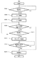
図2は、制御部130の第1例示動作を示すフローチャート200である。
2−1 フローチャート200の概略
まず、フローチャート200の概略について説明する。
2 First Illustrated Operation of
2-1 Outline of
ステップS202において、制御部130は、吸引センサ106からの測定値が、第1閾値Thre1を上回ったか否かを判定する。測定値が第1閾値Thre1を上回っていれば、ステップS204へ進み、そうでなければ、ステップS202へ戻る。
In step S202, the
ステップS204において、制御部130はタイマを起動し、ステップS206において、制御部130は、電源から霧化部104のヒータに電力P1で給電がなされるようにする。
In step S204, the
ステップS208において、制御部130は、タイマの経過時間が既定時間Δt1に達しているか否かを判定する。タイマの経過時間がΔt1に達していなければ、ステップS210に進み、達していれば、ステップS216に進む。
In step S208, the
ステップS210において、制御部130は、吸引センサ106からの測定値が、第1閾値Thre1より大きい第2閾値Thre2を上回ったか否かを判定する。測定値が第2閾値Thre2を上回っていれば、ステップS212へ進み、そうでなければ、ステップS208に戻る。
In step S210, the
ステップS212において、制御部130は、電源から霧化部104のヒータに、P1より大きい電力P2で給電がなされるようにする。
ステップS214において、制御部130は、給電停止条件を満たしたか否かを判定する。給電停止条件を満たしていればステップS216に進み、そうでなければステップS214に戻る。
In step S212, the
In step S214, the
ステップS216において、制御部130は、給電を停止させる。
2−2 フローチャート200の詳細
次に、フローチャート200の動作等の詳細について説明する。
In step S216, the
2-2 Details of
2−2−1 測定値
ステップS202及びS210における測定値は、本例示動作において、吸引センサ106からの生の信号の値、例えば電圧値ではなく、当該生の信号の値から求められた圧力[Pa]又は流量[m3/s]の値であり、吸引が生じたときに正の値をとることを意図している。また、測定値は、ローパスフィルタ等によるフィルタ処理後のものや、単純平均値や移動平均値といった平滑化されたものであってよい。なお、測定値として吸引センサからの生の信号の値を用いてもよいことは言うまでもない。この点について、以下、その他の例示動作においても同様である。なお、圧力と流量の次元としては、例えばそれぞれ[mmH2O]や[L/min]といった任意の単位系を使用してよい。
2-2-1 Measured value The measured value in steps S202 and S210 is not the value of the raw signal from the
2−2−2 閾値
ステップS202及びステップS210における第1閾値Thre1及び第2閾値Thre2ついて、図3A及び3Bを参照して詳述する。
2-2-2 Thresholds The first thresholds Thr1 and the second thresholds Thr2 in steps S202 and S210 will be described in detail with reference to FIGS. 3A and 3B.
310は、吸引が生じていないときの、吸引センサ106からの時間にわたる実際の測定値を示している。吸引が生じていないとき、吸引センサ106からの時間にわたる理想的な測定値は0値で一定となるはずであるが、実際の測定値310には0値からの変動が含まれている。この変動は、エアロゾル生成装置100が存在する周囲環境の人の話し声等による空気の振動や、回路内の熱擾乱等によって生ずる背景ノイズによるものである。また、この背景ノイズには他にも、エアロゾル生成装置100が存在する周囲環境の気圧変化や、エアロゾル生成装置100に加えられた衝撃に起因する。さらには吸引センサ106に静電容量型のMEMS(Micro Electro Mechanical Systems)センサを用いる場合は、電極板の振動が収束するまでの出力値も、この背景ノイズの要因となり得る。第1閾値Thre1は、予熱を応答性良く行うために、多少の背景ノイズを拾い得る値に設定することができる。例えば、図3Aにおいて、測定値310の一部311は、第1閾値Thre1を多少超えている。即ち、
Thre1−0〜Npmax (1)
としてよく、ここで、Npmaxは背景ノイズの時間にわたる正の最大値である。
Three1-0 to N pmax (1)
Here, N pmax is a positive maximum value of background noise over time.
320は、第1閾値Thre1程度の測定値が得られる吸引が生じたときの、背景ノイズ込みの実際の測定値を示している。第1閾値Thre1は、本来、この程度の吸引を検出するものである。第2閾値Thre2は、この程度の吸引が生じたときでもノイズを拾わないように設定することができ、即ち、
Thre1+Npmax<Thre2 (2)
とすることができる。ここで、(1)式の特別な場合として
Thre1−0=Npmax (3)
を考えると、(2)式は以下のように変形できる。
Three1 + N pmax <Thre2 (2)
Can be. Here, as a special case of Eq. (1), Three1-0 = N pmax (3)
Considering, equation (2) can be transformed as follows.
Thre1+Thre1−0<Thre2
Thre1<Thre2−Thre1 (4)
(4)式は、第2閾値Thre2と第1閾値Thre1との差分が、第1閾値Thre1よりも大きければ、エアロゾルを生じさせることなく予熱をすべき状況と、エアロゾルを生じさせるべき状況とを、背景ノイズの大きさを決定することなく明確に区別できることを示している。言い換えると、第1閾値Thre1と第2閾値Thre2とを誤認することがなくなり、測定値が第1閾値Thre1より大きく第2閾値Thre2以下の場合の給電量であるP1と、測定値が第2閾値Thre2より大きい場合の給電量であるP2を適切な値に設定すれば、確実なタイミングでエアロゾルの生成を開始することができる。
Three1 + Three1-0 <Thre2
Three1 <Thre2-Thre1 (4)
In the equation (4), if the difference between the second threshold value Thr2 and the first threshold value Thr1 is larger than the first threshold value Thr1, the situation where the preheating should be performed without generating the aerosol and the situation where the aerosol should be generated are determined. , Shows that the background noise can be clearly distinguished without determining the magnitude. In other words, the first threshold value Thr1 and the second threshold value Thr2 are no longer misidentified, and P1 which is the amount of power supplied when the measured value is larger than the first threshold value Thr1 and equal to or less than the second threshold value Thr2, and the measured value is the second threshold value. If P2, which is the amount of power supplied when the value is larger than Thr2, is set to an appropriate value, aerosol generation can be started at a certain timing.
2−2−3 給電停止条件
ステップS214における給電停止条件の一例は、吸引センサ106からの測定値が、第2閾値Thre2以上である第3閾値Thre3を下回ることである。このような第3閾値Thre3と、第2閾値Thre2及び第1閾値Thre1との関係について、再び図3A及び3Bを参照しつつ詳述する。
2-2-3 Power supply stop condition An example of the power supply stop condition in step S214 is that the measured value from the
図3A及び3Bのように、第2閾値Thre2は、第3閾値Thre3より第1閾値Thre1に近いように設定することができる。このように設定することで、より早くエアロゾル生成を開始できるため、結果的に早めに給電を停止できる。またユーザの吸引に対してより違和感の少ない態様でエアロゾル生成を行える。 As shown in FIGS. 3A and 3B, the second threshold value Thre2 can be set to be closer to the first threshold value Thre1 than the third threshold value Thre3. By setting in this way, aerosol generation can be started earlier, and as a result, power supply can be stopped earlier. In addition, the aerosol can be generated in a manner that is less uncomfortable with the suction of the user.
また、図3A及び3Bとは異なり、第2閾値Thre2は、第1閾値Thre1より第3閾値Thre3に近いか又は第3閾値Thre3と等しいように設定することができる。このように設定することで、給電停止条件を測定値が第3閾値Thre3以下であるという単純なものとした場合であっても、測定値が徐々に増加するという仮定のもとで、最初にステップS214を実行するときに測定値が第3閾値Thre3以下となる可能性が減り、エアロゾル生成の強制終了を回避しやすくなる。 Also, unlike FIGS. 3A and 3B, the second threshold Thr2 can be set to be closer to the third threshold Thr3 than the first threshold Thr1 or equal to the third threshold Thr3. By setting in this way, even if the power supply stop condition is as simple as the measured value being the third threshold value Thre3 or less, the measured value is first assumed to increase gradually. When step S214 is executed, the possibility that the measured value becomes the third threshold value Thre3 or less is reduced, and it becomes easy to avoid the forced termination of aerosol generation.
2−2−4 電源及び電力
ステップS206及びステップS212において、電源は、バッテリ114と電力制御部135とから少なくとも構成されるものを意図したものである。この点について、以下、その他の例示動作においても同様である。
2-2-4 Power supply and power In steps S206 and S212, the power supply is intended to be composed of at least a
また、ステップS206及びステップS212において、ヒータに給電される電力は、時間にわたり一定であるか、又は、時間にわたり変化するが単位時間当たりの給電量が一定となるように供給することができる。本例示動作において、電力P1及びP2の値は、単位時間当たりの給電量(エネルギー)を意図している。但し、単位時間の長さは1sを含む任意の長さを意図したものであり、例えば、給電にPWM制御を用いる場合、PWM1周期の長さであり得る。なお、単位時間の長さが1sでない場合、電力P1及びP2の物理量は「電力」でないが、便宜上、「電力」と表記している。この点について、以下、その他の例示動作においても同様である。 Further, in steps S206 and S212, the electric power supplied to the heater can be supplied so as to be constant over time or to be constant over time but the amount of electric power supplied per unit time is constant. In this exemplary operation, the values of the electric powers P1 and P2 are intended to be the amount of power supplied (energy) per unit time. However, the length of the unit time is intended to be an arbitrary length including 1s, and for example, when PWM control is used for power feeding, it may be the length of one PWM cycle. When the length of the unit time is not 1s, the physical quantities of the electric powers P1 and P2 are not "electric power", but are described as "electric power" for convenience. This point is the same in the following other exemplary operations.
電力P1及びP2について、図4を参照して詳述する。図4は、吸引センサ106の測定値410(実線)の時間にわたる変化(以下、「パフプロファイル」または「測定値のプロファイル」ともいう。)と、霧化部104のヒータに供給される電力420(点線)との時間にわたる変化を表している。図4は、測定値410が第1閾値Thre1を上回ったときt1に、電力P1での給電が開始されること、電力P1での給電の開始から既定時間Δt1の経過前に測定値410が第2閾値Thre2を上回っているため、測定値410が第2閾値Thre2を上回ったときt2に、電力P2での給電が開始されること、及び、測定値410が第3閾値Thre3を下回ったときt3に、給電が停止されることを示している。なお、時刻t1における判定は図2のフローチャートにおけるステップS202の判定,時刻t2における判定は図2のフローチャートのステップS210における判定,時刻t3における判定は図2のフローチャートのステップS214における判定,既定時間Δt1は図2のフローチャートのステップS208におけるΔt1にそれぞれ相当する。
The electric powers P1 and P2 will be described in detail with reference to FIG. FIG. 4 shows changes in the measured value 410 (solid line) of the
なお、図4に表したパフプロファイルは、説明のために簡略化した例示のものであることに留意されたい。制御部130は、1回のある期間、例えば1回の給電サイクルにおいて得られた測定値に基づくパフプロファイル、複数回のある期間において得られた測定値の平均に基づくパフプロファイル、複数回のある期間において得られた測定値の回帰分析に基づくパフプロファイル等に基づき、給電を制御することができる。なお、「給電サイクル」は、給電を開始してから停止するまでの期間を含み、測定値が0若しくは所定の微小値を上回ってから0に戻る若しくは所定の微小値を下回るまでの期間、又は、当該期間の前及び後ろの一方若しくは双方に所定の時間を加えた期間であってよい。図4に示されたグラフの時間軸の左端から右端までの期間は、「給電サイクル」の一例である。この点について、以下、その他の例示動作においても同様である。
It should be noted that the puff profile shown in FIG. 4 is a simplified example for the sake of explanation. The
電力P1は、測定値410が第1閾値Thre1より大きく且つ第2閾値Thre2以下の期間に供給されるものである。この期間が霧化部104のヒータの予熱として用いられる場合には、電力P1は以下の式を満たさなければならない。
The electric power P1 is supplied during a period in which the measured
Jatomize/Δt1>P1/Δtunit (5)
ここで、Jatomizeは霧化部104において霧化が生ずる最小のエネルギーである。なお、Jatomizeはエアロゾル源の組成や霧化部104のヒータの構成に基づいて理論的又は実験的に求められてもよい。また、Δtunitは単位時間の長さであり、単位時間の長さが1sの場合、「/Δtunit」は省略してよい。なお、Jatomizeは必ずしも固定値である必要はなく、条件や他の変数によって変動する変数でもよい。一例として制御部130は、エアロゾル源の残量に応じてJatomizeを修正してもよい。
J atomize / Δt1> P1 / Δt unit (5)
Here, Jatomize is the minimum energy at which atomization occurs in the
電力P2は、測定値410が第2閾値Thre2を越えた場合に供給されるもので、霧化部104において霧化を生じさせるための電力である。従って、電力P2は、霧化部104に悪影響を与えない、例えばそのヒータに過熱による故障を引き起こさない限度において、できる限り大きい値であることが好ましく、少なくとも以下の条件を満たすことができる。
The electric power P2 is supplied when the measured
P2>P1 (6)
また、電力P1は、(5)式を満たすのであれば、可能な限り大きくすることができ、それによって、既定期間Δt1を小さくすることができる。よって、0値<P1<P2である電力P1は、0値ではなくP2により近いように設定することができる。
P2> P1 (6)
Further, the electric power P1 can be increased as much as possible as long as it satisfies the equation (5), whereby the predetermined period Δt1 can be decreased. Therefore, the power P1 having 0 value <P1 <P2 can be set to be closer to P2 instead of 0 value.
2−2−5 フローチャート200から導ける処理
フローチャート200が含む一連のステップは、吸引センサ106の測定値が第1閾値Thre1より大きく第2閾値Thre2以下の場合の電源からの給電量を、高々所定の値(電力P1×既定時間Δt1)とする処理の一例である。
2-2-5 Processing Derived from
このような処理によれば、吸引センサ106からの測定値が第1閾値Thre1より大きく且つ第2閾値Thre2以下の場合の電源からの給電量を第1の値とおいた場合、第1の値は必ず所定の値以下となるから、当該測定値が第2閾値Thre2より大きい場合の給電量が第1の値より大きくなるように給電を制御することが可能である。従って、このような処理によれば、例えば背景ノイズの影響により意図せず測定値が頻繁に超えてしまうような値に第1閾値Thre1を設定した場合であっても、無駄な電力消費やエアロゾル源の消費が抑制されることになる。
According to such processing, when the measured value from the
上記所定の値は、霧化部104においてエアロゾルの生成が開始される給電量未満とすることができる。このような値を用いることにより、第1の値の給電量によって、霧化部104において霧化は発生しないが、霧化部104のヒータの予熱が行われることになる。予熱によれば、無駄なエアロゾル源の消費を生じさせず、且つ、意図しないエアロゾル発生による周囲への影響を与えずに、意図したエアロゾルの発生を応答性よく開始することができる。別の観点から述べると、第1の値の給電量を与えるための電力又は単位時間当たりの電力量P1と、既定時間Δt1との少なくとも一方は、第1の値が、エアロゾル源からエアロゾルの生成が開始される給電量以下になるように設定することができる。なお、既定時間Δt1は既定の上限と下限の間で設定されるものとすることができる。既定時間Δt1の上限の一例としては、500msec,300msec,100msecなどが挙げられる。また既定時間Δt1の下限の一例としては、10msec,30msecなどが挙げられる。
The above-mentioned predetermined value can be less than the amount of power supplied to start the generation of aerosol in the
フローチャート200が含む一連のステップは、測定値が第1閾値Thre1を超えてから又は電力P1での給電の開始から、既定時間Δt1内に測定値が第2閾値Thre2より大きくならない場合、給電を停止する処理の一例でもある。このような処理によれば、通電開始に関連した第1閾値Thre1を、ノイズを拾い得るようなピーキーな値に設定したとしても、ノイズによりほぼ常時通電するという状況にはならないから、電源の蓄電量の低下を避けることができる。
The series of steps included in the
2−3 フローチャート200の変形例
更に、フローチャート200の変形例について説明する。
上述したように、吸引センサ106としては、圧力又は流量センサと操作ボタンとの双方を用いることができる。吸引センサ106として操作ボタンも設けられている場合、ステップ202は、測定値が第1閾値Thre1を上回ったか否かではなく、操作ボタンが押下されたか否かを判定するものであってもよい。
2-3 Modification example of the
As described above, as the
また、ステップS206はステップ204の前に実行されてもよいし、ステップS204とステップS206とを同時に(並列に)実行してもよい。
ステップS214における給電停止条件の別例は、電源が第2の値を給電した後に、吸引センサ106からの測定値が第3閾値Thre3を下回ることである。第2の値は、測定値が第2閾値Thre2を超えた場合の、電源からの最低限の給電量であり、測定値が第2閾値Thre2を越える前の給電量である上述した第1の値よりも大きくすることができる。この場合、測定値が第2閾値Thre2を越える前の給電量は、第2の値より小さいことになる。
Further, step S206 may be executed before
Another example of the power supply stop condition in step S214 is that the measured value from the
更に、フローチャート200は、ステップS204を削除し、ステップS208を、当該ステップの時点での延べ給電量が所定の値以下であるか否かを判定するステップとするように変形することができる。変形後のフローチャート200が含む一連のステップは、吸引センサ106の測定値が第1閾値Thre1より大きく第2閾値Thre2以下の場合の電源からの給電量を、最大でも所定の値(電力P1×既定時間Δt1)とする処理の別例である。なお、当該処理は、上に示した2例に限定されないことに留意されたい。
Further, the
3 制御部130の第2例示動作
図5Aは、制御部130の第2例示動作を示すフローチャート500である。
3−1 フローチャート500の概略
まず、フローチャート500の概略について説明する。
3 Second Illustrated Operation of
3-1 Outline of
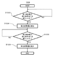
ステップS502において、制御部130は、第1条件を満たしたか否かを判定する。第1条件を満たしている場合、ステップS504へ進み、そうでなければ、ステップS502へ戻る。ステップS504において、制御部130は、霧化部104のヒータに給電される電力の値(上述したように、単位時間当たりの給電量。以下、「単位給電量」という。)を増加させる。
In step S502, the
ステップS506において、制御部130は、第2条件を満たしたか否かを判定する。第2条件を満たしている場合、ステップS508へ進み、そうでなければ、ステップS506へ戻る。ステップS508において、制御部130は、第3条件を満たしたか否かを判定する。第3条件を満たしている場合、ステップS510へ進み、そうでなければ、ステップ506へ戻る。ステップS510において、制御部130は、単位給電量を減少させる。
In step S506, the
ステップS512において、制御部130は、第4条件を満たしたか否かを判定する。第4条件を満たしている場合、制御部130が単位給電量を増加させるステップS514へ進み、そうでなければ、フローチャート500は終了する。
In step S512, the
3−2 フローチャート500の詳細
次に、フローチャート500の動作等の詳細について説明する。
3−2−1 第1条件
ステップS502における第1条件は、吸引センサ106からの測定値が、第1閾値Thre1又は第2閾値Thre2を上回っていることであってよい。
3-2 Details of
3-2-1 First condition The first condition in step S502 may be that the measured value from the
3−2−2 第2条件
ステップS506における第2条件は、吸引センサ106からの測定値が、第3閾値Thre3を下回っていることであってよい。ここで、第3閾値Thre3は更新することができる。
3-2-2 Second condition The second condition in step S506 may be that the measured value from the
第3閾値Thre3の更新手法の第1例として、制御部130は、給電を開始してから停止するまでの期間又は給電サイクル毎に、測定値の最大値を算出し、記憶しておき、算出した複数の最大値に基づき、第3閾値Thre3を更新することができる。
As the first example of the update method of the third threshold value Thr3, the
より詳細には、制御部130は、算出した複数の最大値から導出した、平均値vmax_aveに基づき、第3閾値Thre3を更新することができる。単純な平均演算の一例を以下に示す。
More specifically, the

また、加重平均演算の一例を以下に示す。 An example of the weighted average operation is shown below.
ここで、式(7)及び(8)において、Nは最大値を算出した期間の数であり、vmax(i)はi番目の期間の最大値(iの値が大きいほどより新しいことを示す。)である。このような平均演算は、エアロゾル生成装置100を長期間使用する場合に有用である。特に、加重平均演算によると、より最近の給電を開始してから開始した当該給電が停止するまでの期間について算出された最大値に、より大きな重みが割り当てられるため、エアロゾル生成装置100を長期間使用した場合のパフプロファイルの変化に対応できる。
Here, in the equations (7) and (8), N is the number of periods for which the maximum value is calculated, and v max (i) is the maximum value of the i-th period (the larger the value of i, the newer it is. Shown.). Such an averaging calculation is useful when the
第3閾値Thre3を更新すべき値を求める式の例を以下に示す。
Thre3=vmax_ave×α (9)
ここで、αは0より大きく1以下の値であり、好ましくは第3閾値Thre3が第2閾値Thre2より大きくなる値である。
An example of the formula for obtaining the value to update the third threshold value Thr3 is shown below.
Three = v max_ave × α (9)
Here, α is a value larger than 0 and 1 or less, and preferably a value in which the third threshold value Thre3 is larger than the second threshold value Thre2.
第3閾値Thre3の更新手法の第2例として、制御部130は、給電を開始してから停止するまでの期間又は給電サイクル毎に、測定値の変化即ちプロファイルを記憶し、記憶した複数の測定値の変化に基づき、第3閾値Thre3を更新することができる。特に、第3閾値Thre3は、測定値の変化の持続時間(例えば、測定値が0又は所定の微小値を上回ってから0に戻る又は所定の微小値を下回るまでの長さ)の平均値Δtduration_aveから既定値Δt2を引いた値に基づき更新することができる。第3閾値Thre3を更新すべき値を求める式の例を以下に示す。
As a second example of the update method of the third threshold value Thr3, the
Thre3=v(Δtduration_ave−Δt2) (11)
ここで、図6Aを参照して説明すると、v(t)はパフプロファイル610を表す関数であり、Δtduration_ave及びΔt2は、図に示された時間に相当する。なお、図6Aに表したパフプロファイルは、複数回のある期間において得られた測定値の平均に基づくものであることを意図しているが、説明のために簡略化した例示のものであることに留意されたい。
Three = v (Δt duration_ave −Δt2) (11)
Here, to explain with reference to FIG. 6A, v (t) is a function representing the
なお、本実施形態においては、測定値の持続時間を導出するにあたっては、測定値が0又は所定の微小値を上回ってから0に戻る又は所定の微小値を下回るまでの長さを用いた。これに代えて、0又は所定の微小値を連続して複数下回るまでの長さを用いてもよい。またこれらと併せて、測定値の時間微分値を用いてもよい。
3−2−3 第1条件と第2条件の比較
ウィック112の熱容量が大きい場合、ユーザの吸引に対して違和感なくエアロゾル生成を行うためには、制御部130が単位給電量を増加させるタイミングと減少させるタイミングを早めることが好ましい。すなわち、0から連続的に増加して最大値に至り、その後に連続的に減少して0に至るという理想的なユーザプロファイルを考慮すると、図5AのステップS502における第1条件で用いる第1閾値Thre1又は第2閾値Thre2は、図5AのステップS506における第2条件で用いる第3閾値Thre3より小さい値であることが好ましい。
In the present embodiment, in deriving the duration of the measured value, the length from when the measured value exceeds 0 or a predetermined minute value to when it returns to 0 or falls below a predetermined minute value is used. Instead of this, a length up to 0 or a plurality of consecutively lower than a predetermined minute value may be used. In addition to these, the time derivative value of the measured value may be used.
3-2-3 Comparison between the first condition and the second condition When the heat capacity of the
しかし、後述する第3条件を用いずに、第1条件と第2条件のみを用いて制御部130が単位給電量を増減させる場合、次のような不具合が生じ得る。第1条件で用いる第1閾値Thre1又は第2閾値Thre2が、第2条件で用いる第3閾値Thre3より小さいことから、第1条件が満たされた直後に第2条件が満たされ、増加した単位給電量によるエアロゾル生成が行われないまま、単位給電量が減少する。より詳述すると、ステップS502における第1条件で用いる第1閾値Thre1又は第2閾値Thre2を上回った測定値は、ステップS506において第3閾値Thre3を下回ったか否かが判断される。測定値が理想的には連続的に変化する点と制御部130の制御周期や演算速度を考慮すると、第1閾値Thre1又は第2閾値Thre2を上回った直後の測定は、第3閾値未満である可能性が高い。
However, when the
仮に理想通りにユーザプロファイルが変化するならば、ユーザプロファイルの最大値は極大値と同義であることから、例えば、リアルタイムに変化するユーザプロファイルにおいて測定値の変化を計算し、測定値が最大値(極大値)に達した後に、測定値が第3閾値を下回ったか否かを判断すればこの不具合を容易に解消できる。しかし、現実のユーザプロファイルには大きな個人差があり、加えて図3Aと図3Bにおいて説明した測定値に混ざり込む背景ノイズが存在するため、複数の極大値が存在してしまうことから、この不具合を解消できない。そこで本実施形態では、この不具合を解消すべく第3条件を導入する。 If the user profile changes as ideal, the maximum value of the user profile is synonymous with the maximum value. Therefore, for example, in a user profile that changes in real time, the change in the measured value is calculated and the measured value is the maximum value ( This problem can be easily solved by determining whether or not the measured value has fallen below the third threshold value after reaching the maximum value). However, there are large individual differences in the actual user profile, and in addition, there is background noise mixed with the measured values described in FIGS. 3A and 3B, so that a plurality of maximum values exist. Cannot be resolved. Therefore, in the present embodiment, the third condition is introduced in order to solve this problem.
3−2−4 第3条件
ステップS508における第3条件は、第1条件及び第2条件とは異なる条件である。従って、第3条件は、第1条件と同時に満たされない任意の条件であることができる。このような第3条件によると、第1条件が満たされ、単位給電量が増加した直後に減少するといった事態を抑制することができる。また、第3条件は、第2条件より後に満たす(言い換えると、第2条件が第3条件より先に満たされる)ことが可能な任意の条件であることができる。このような第3条件によると、吸引センサ106からの測定値が第3閾値Thre3以下となってもすぐには単位給電量が減少せず、給電を続行できる。
3-2-4 Third condition The third condition in step S508 is a condition different from the first condition and the second condition. Therefore, the third condition can be any condition that is not satisfied at the same time as the first condition. According to such a third condition, it is possible to suppress a situation in which the first condition is satisfied and the unit power supply amount decreases immediately after the increase. Further, the third condition can be any condition that can be satisfied after the second condition (in other words, the second condition is satisfied before the third condition). According to such a third condition, even if the measured value from the
3−2−4−1 測定値に基づく第3条件
第3条件は、吸引センサ106からの測定値に基づく条件であることができる。このような第3条件によると、吸引の強さを考慮しつつ、単位給電量が増加した直後に減少するといった事態を回避できる。
3-2-4-1 Third condition based on the measured value The third condition can be a condition based on the measured value from the
具体的にいうと、第3条件の第1例は、測定値の時間微分に基づく条件である。このような条件によると、吸引の強さの変化も考慮することで、ユーザの感覚に沿った形で単位給電量を減少させるか否かを判断できる。より詳細には、第3条件は、測定値の時間微分が0又は0より小さい第4閾値Thre4以下であるという条件であることができる。このような条件によると、吸い込みの強さが増え続けている間は、単位給電量が減少することがなくなる。
なお、前述したように測定値には背景ノイズが混ざり込む。従って、厳密には吸い込みの強さが増え続けている場合でも、測定値の時間微分は0より小さくなる可能性がある。第3条件を、測定値の時間微分が0より小さい第4閾値Thre4以下であるという条件とすることで、測定値の時間微分が瞬時的にマイナスとなる場合でも、単位給電量が減少することがなくなる。ただし、あまり第4閾値Thre4の絶対値を大きい値としてしまうと、吸い込みの弱さが減り続けパフの終わりが近づいていることを認識できなくなってしまう。従って、より精度を高めるためには第4閾値Thre4は背景ノイズの大きさを考慮して設定された値でもよい。
背景ノイズの大きさを考慮する場合は、エアロゾル生成装置100の製造時に背景ノイズの大きさを考慮した固定値を第4閾値Thre4としてメモリ140に記憶させてもよい。または、フローチャート500を実行させる前に、キャリブレーションのような形で背景ノイズの時間変化を記憶し続け、そこから導出した最大値や平均値に基づき第4閾値Thre4を設定してもよい。
本実施形態においては、第3条件には、測定値の時間微分が0又は0より小さい第4閾値Thre4以下であるという条件を用いた。これに代えて、測定値の時間微分が0又は0より小さい第4閾値Thre4以下という点を、既定時間にわたって連続して満たしたという条件を第3条件に用いてもよい。背景ノイズが図3A又は図3Bのように変化するならば、吸い込みの強さが増え続けている間は、測定値の時間微分が0又は0より小さい第4閾値Thre4以下になり続けないからである。
Specifically, the first example of the third condition is a condition based on the time derivative of the measured value. According to such a condition, it is possible to determine whether or not to reduce the unit power supply amount in a manner according to the user's feeling by considering the change in the suction strength. More specifically, the third condition can be a condition that the time derivative of the measured value is 0 or less than or equal to the fourth threshold Thre4, which is less than 0. Under such conditions, the unit power supply amount does not decrease while the suction strength continues to increase.
As described above, background noise is mixed in the measured value. Therefore, strictly speaking, the time derivative of the measured value may be smaller than 0 even when the suction strength continues to increase. By setting the third condition as a condition that the time derivative of the measured value is less than 0 and equal to or less than the fourth threshold Thre4, the unit feed amount is reduced even when the time derivative of the measured value becomes negative instantaneously. Is gone. However, if the absolute value of the fourth threshold value Thr4 is set too large, the weakness of suction continues to decrease and it becomes impossible to recognize that the end of the puff is approaching. Therefore, in order to further improve the accuracy, the fourth threshold value Thr4 may be a value set in consideration of the magnitude of background noise.
When considering the magnitude of the background noise, a fixed value considering the magnitude of the background noise may be stored in the
In the present embodiment, as the third condition, the condition that the time derivative of the measured value is 0 or less than the fourth threshold value Thre4 less than 0 is used. Alternatively, the condition that the time derivative of the measured value is 0 or the fourth threshold value Thre4 or less, which is smaller than 0, is continuously satisfied over a predetermined time may be used as the third condition. If the background noise changes as shown in FIG. 3A or FIG. 3B, the time derivative of the measured value does not continue to be 0 or less than the fourth threshold Thr4, which is smaller than 0, while the suction strength continues to increase. is there.
第3条件の第2例は、測定値が、第2閾値Thre2以上の第5閾値Thre5を超えた後で第2閾値Thre2を下回ったという条件である。このような条件によると、第5閾値Thre5を想定される最大値近傍の値とすることにより、少なくとも最大値近傍までは単位給電用が減少しないようにすることができる。 The second example of the third condition is a condition that the measured value exceeds the fifth threshold value Thre5, which is equal to or higher than the second threshold value Thre2, and then falls below the second threshold value Thre2. According to such a condition, by setting the fifth threshold value Thr5 to a value near the assumed maximum value, it is possible to prevent the unit power supply from decreasing at least near the maximum value.
ここで、第5閾値Thre5は、更新することができる。
第5閾値Thre5の更新手法の第1例として、制御部130は、給電を開始してから停止するまでの期間又は給電サイクル毎に、測定値の最大値を算出し、記憶しておき、算出した複数の最大値に基づき、第5閾値Thre5を更新することができる。より詳細には、制御部130は、算出した複数の最大値の平均値に基づき、第5閾値Thre5を更新することができる。平均値を求めるための平均演算は、第3閾値Thre3の更新に関連して上述した平均演算を用いることができる。第5閾値Thre5を更新すべき値は、以下のように求めることができる。
Here, the fifth threshold Thre5 can be updated.
As a first example of the method for updating the fifth threshold value Thr5, the
Thre5=vmax_ave−Δv1 (10)
ここで、Δv1は0以上の所与の値である。第5閾値Thre5を更新することで、第5閾値Thre5に適切な大きさの値が設定され、不適切なタイミングで単位給電量が減少する可能性が減少する。
Three5 = v max_ave −Δv1 (10)
Here, Δv1 is a given value of 0 or more. By updating the fifth threshold value Thre5, a value having an appropriate size is set for the fifth threshold value Thre5, and the possibility that the unit power supply amount is reduced at an inappropriate timing is reduced.
第5閾値Thre5の更新手法の第2例として、制御部130は、まず第3閾値Thre3を更新し、更新した第3閾値Thre3以上となるように第5閾値Thre5を更新することができる。第5閾値Thre5を更新すべき値を求める式の例を以下に示す。
As a second example of the method for updating the fifth threshold value Thre5, the
Thre5=Thre3+Δv2 (11)
ここで、Δv2は0以上の所与の値である。
3−2−4−2 不感期間に基づく第3条件
第3条件として、不感期間を利用してもよい。即ち、第3条件の第3例は、第1条件が満たされてから既定の不感期間Δtdeadが経過したという条件である。このような第3条件によると、少なくとも不感期間が経過するまでは単位給電量が減少しないため、単位給電量が増加した直後に減少するといった事態を抑制できる。
Thre5 = Thre3 + Δv2 (11)
Here, Δv2 is a given value of 0 or more.
3-2-4-2 Third condition based on the dead period As the third condition, the dead period may be used. That is, the third example of the third condition is a condition that the predetermined dead period Δt dead has elapsed since the first condition was satisfied. According to such a third condition, since the unit power supply amount does not decrease at least until the dead period elapses, it is possible to suppress a situation in which the unit power supply amount decreases immediately after the increase.
不感期間Δtdeadは更新することができる。例えば、制御部130は、給電サイクル毎に、第1条件が満たされてから測定値が最大値に至るまでの第1所要時間と、第1条件が満たされてから当該第1条件が満たされなくなるまでの第2所要時間の少なくとも一方を算出し、複数の第1所要時間と複数の第2所要時間との少なくとも一方に基づき、不感期間Δtdeadを更新することができる。
The dead period Δt dead can be updated. For example, the
より詳細には、制御部130は、複数の第1所要時間の平均値と複数の第2所要時間の平均値との少なくとも一方に基づき、不感期間Δtdeadを更新することができる。単純な平均演算の一例を以下に示す。
More specifically, the
また、加重平均演算の一例を以下に示す。 An example of the weighted average operation is shown below.
なお、式(12)及び(13)において、Nは第1所要時間又は第2所要時間を算出した期間の数であり、Δt(i)はi番目の期間の第1所要期間又は第2所要期間(iの値が大きいほどより新しいことを示す。)である。このような平均演算は、エアロゾル生成装置100を長期間使用する場合に有用であり、特に、加重平均演算によると、より最近の給電を開始してから開始した当該給電が停止するまでの期間について算出された第1所要期間又は第2所要期間に、より大きな重みが割り当てられるため、エアロゾル生成装置100を長期間使用した場合のパフプロファイルの変化に対応できる。
In the formulas (12) and (13), N is the number of periods for which the first required time or the second required time is calculated, and Δt (i) is the first required period or the second required period of the i-th period. The period (the larger the value of i, the newer it is). Such an average calculation is useful when the
不感期間Δtdeadを更新すべき値を求める式の3つの例を以下に示す。 The following are three examples of equations for finding the value at which the dead period Δt dead should be updated.
ここで、上式における各変数の関係について、図6Bを参照されたい。特に、tover_Thre1_aveは測定値が0又は所定の微小値を上回ってから第1条件を満たすまでの平均値である。従って、tmax_ave−tover_Thre1_aveは上記第1所要時間の平均値に相当する。tunder_Thre1_aveは測定値が0又は所定の微小値を上回ってから第1条件を満たさなくなるまでの平均値である。従って、tunder_Thre1_ave−tover_Thre1_aveは上記第2所要時間の平均値に相当する。Δt3、Δt4及びΔt5はその大きさが0以上の所与の値であり、好適には、図6Bにおいて640の示す値が第3閾値Thre3となるように設定される。不感期間Δtdeadを更新することで、不感期間Δtdeadに適切な大きさの値が設定され、予期しないタイミングで単位給電量が減少する可能性が減少する。 Here, refer to FIG. 6B for the relationship of each variable in the above equation. In particular, tover_Thre1_ave is an average value from when the measured value exceeds 0 or a predetermined minute value until the first condition is satisfied. Therefore, t max_ave −t over_Thre1_ave corresponds to the average value of the first required time. tunder_Thre1_ave is an average value from when the measured value exceeds 0 or a predetermined minute value until the first condition is no longer satisfied. Therefore, tunder_Thre1_ave- t over_Thre1_ave corresponds to the average value of the second required time. Δt3, Δt4, and Δt5 are given values having a magnitude of 0 or more, and preferably, the value indicated by 640 in FIG. 6B is set to be the third threshold value Thr3. By updating the dead period Delta] t dead, is set to the value of the appropriate size insensitive period Delta] t dead, possibly a unit feeding amount decreases in an unexpected timing is reduced.
3−2−4−3 その他の第3条件
第3条件の第4例は、第3条件を判定する時点で、当該時点までに出力された測定値が最大となったときから所定時間以上経過しているという条件である。
3-2-4-3 Other third conditions In the fourth example of the third condition, at the time of determining the third condition, a predetermined time or more has elapsed from the time when the measured value output up to that time became the maximum. It is a condition that you are doing.
3−2−4−4 第3条件の選択
第3条件は、複数の第3条件から選択することができる。図7は、様々なパフプロファイルを表すグラフである。図7からわかるように、第3条件として適切なものは、パフプロファイルごとに異なる。例えば、710で示されるパフプロファイルに対しては、最大値に至るまえに極大値を持つため、換言すれば最大値に至る前に測定値の時間微分がマイナスの値になるため、第3条件において微分値を用いるもの(第1例)が使いにくい。また、720で示されるパフプロファイルに対しては、測定値が概して小さいため、第3条件において複数の閾値を用いるもの(第2例)が、複数の閾値に対して互いに有意差を持たせにくく、使いにくい。更に、730で示されるパフプロファイルに対しては、最大値に至るまで時間がかかるため、第3条件において不感期間を用いるもの(第3例)が使いにくい。従って、制御部130は、複数の第3条件を備えた第3条件群から、第3条件を選択可能な選択モードを実行可能であってもよい。特に、制御部130は、吸引センサ106の測定値を記憶し、記憶した測定値に基づき、例えば記憶した測定値に基づくパフプロファイルに基づき、第3条件群から第3条件を選択することができる。
3-2-4-4 Selection of the third condition The third condition can be selected from a plurality of third conditions. FIG. 7 is a graph showing various puff profiles. As can be seen from FIG. 7, the appropriate third condition differs for each puff profile. For example, for the puff profile shown by 710, since it has a maximum value before reaching the maximum value, in other words, the time derivative of the measured value becomes a negative value before reaching the maximum value, so the third condition. It is difficult to use the one that uses the differential value in (1st example). Further, since the measured values are generally small for the puff profile shown by 720, those using a plurality of threshold values in the third condition (second example) are unlikely to have a significant difference from each other with respect to the plurality of threshold values. , Difficult to use. Further, for the puff profile shown by 730, it takes time to reach the maximum value, so that it is difficult to use the one that uses the dead period in the third condition (the third example). Therefore, the
図8は、第3条件群から第3条件を選択するための例示の方法800を表している。なお、図8において、第3条件群が含む第3条件は、第3条件A、B及びCの3つであると仮定しているが、第3条件群は2以上の任意の数の第3条件を含むことができる。
FIG. 8 represents an
ステップS810において、制御部130は、第3条件Aの除外条件を満たしたかを判定する。第3条件Aの除外条件は、極大値を持つ等の、記憶した測定値の時間微分に基づく条件であることができる。第3条件Aの除外条件を満たしている場合、ステップS815に進み、第3条件Aを候補から外したうえでステップS820にさらに進む。第3条件Aの除外条件を満たしていない場合、ステップS820に進み、従ってこの場合、第3条件Aは候補から外されない。
In step S810, the
ステップS820及び830は、それぞれ、第3条件Aとは異なる第3条件B及びCについて判定する、ステップS810に対応するステップである。ここで、第3条件Bの除外条件は、測定値が概して小さい等の、測定値の最大値に基づく条件であることができる。また、第3条件Cの除外条件は、最大値に至るまで時間がかかる等の、測定値の変化の持続時間に基づく条件であることができる。ステップS825及びS835は、それぞれ、第3条件Aとは異なる第3条件B及びCを候補から外す、ステップS815に対応するステップである。 Steps S820 and 830 are steps corresponding to step S810 for determining the third conditions B and C, which are different from the third condition A, respectively. Here, the exclusion condition of the third condition B can be a condition based on the maximum value of the measured value, such that the measured value is generally small. Further, the exclusion condition of the third condition C can be a condition based on the duration of change of the measured value, such as it takes time to reach the maximum value. Steps S825 and S835 are steps corresponding to step S815, in which the third conditions B and C, which are different from the third condition A, are excluded from the candidates, respectively.
ステップS840において、制御部130は、候補に残った第3条件から第3条件を選択する。但し、候補が複数残っている場合、残った候補から1つの第3条件を選択することができる。また、候補が残っていない場合、制御部130は、第3条件群に含まれる任意の第3条件を選択してもよい。制御部130が複数の第3条件のうちの1以上を選択する手法としては、ランダム選択、予め設定された優先順位に基づく選択、ユーザ選択等が考えられる。なお、エアロゾル生成装置100は、ユーザ選択を受けるための図示しない入力手段を有することができる。また、エアロゾル生成装置100は、WiFiやBluetooth(登録商標)等によりスマートフォン等のコンピュータに接続するための図示しない通信手段を有することができ、接続されたそのようなコンピュータからユーザ選択を受けることができる。
In step S840, the
ステップS850において、制御部130は、選択した第3条件を取得する。選択した第3条件を取得することは、当該条件を判定するためのアルゴリズムに従うプログラムを取得することを含む。第3条件群の取得される可能性ある1以上の第3条件は、メモリ140に予め記憶しておくこともできるし、外部から、例えば、上述したようなスマートフォン等のコンピュータから取得したり、上記通信手段を介してインターネットからダウンロードしたりすることもできる。第3条件を外部やインターネットから取得する場合は、メモリ140に第3条件群に含まれる第3条件の全てを記憶させておく必要がないため、他の用途のためにメモリ140の空き容量を確保できる、高容量のメモリ140を搭載する必要がなくなることによりエアロゾル生成装置100のコストを低減できる、大型のメモリ140を搭載する必要がなくなることによりエアロゾル生成装置100を小型化できる、といった利点が得られることになる。
In step S850, the
ステップS860において、制御部130は、選択された第3条件が満たされているかが判定されるように、自身を構成する。
3−2−5 第4条件
ステップS512における第4条件は、第2条件及び第3条件が満たされてから、既定の復帰期間内に、吸引センサ106からの測定値の時間微分が0を超えたという条件であることができる。このような第4条件によると、ノイズや僅かな吸引の強さの減少によって単位給電量が減少した場合に即座に単位給電量を増加させることができるので、エアロゾル生成装置100の使い勝手がよくなる。
In step S860, the
3-2-5 Fourth condition In the fourth condition in step S512, the time derivative of the measured value from the
3−2−6 単位給電量の増加
ステップS504における単位給電量の増加は、0値からのある大きさの単位給電量への増加であってよい。また、この増加は段階的なものであってもよく、例えば、単位給電量を、0値から第1単位給電量へ、該第1単位給電量から該第1単位給電量より大きい第2単位給電量へ、段階的に変化させてよい。
3-2-6 Increase in unit power supply amount The increase in unit power supply amount in step S504 may be an increase from a value of 0 to a unit power supply amount of a certain magnitude. Further, this increase may be gradual, for example, the unit feed amount is changed from the 0 value to the first unit feed amount, and from the first unit feed amount to the second unit larger than the first unit feed amount. The amount of power supplied may be changed step by step.
ステップS514における単位給電量の増加は、0値から、ステップS504において増加した大きさの単位給電量への増加であってよい。
3−2−7 単位給電量の減少
ステップS510について、単位給電量の減少は、ある大きさの単位電力量から0値への減少であってよい。
The increase in the unit feed amount in step S514 may be an increase from the 0 value to the unit feed amount of the increased magnitude in step S504.
3-2-7 Decrease in unit power supply amount For step S510, the reduction in unit power supply amount may be a decrease from a unit power amount of a certain magnitude to a zero value.
3−3 フローチャート500の変形例
更に、フローチャート500の変形例について説明する。
ステップS508はステップS506の前に実行してもよいし、ステップS506とステップS508とを同時に(並列に)実行してもよい。
3-3 Modification Example of
Step S508 may be executed before step S506, or step S506 and step S508 may be executed at the same time (in parallel).
また、ステップS508は、第1条件が満たされてから既定の判定期間の内で第3条件が満たされない場合に、ステップS510に進むように変形することができる。このようにすることで、第3条件が満たされない場合であっても単位給電量を減少させることができ、通電が止まらないという事態を避けることができる。 Further, step S508 can be modified so as to proceed to step S510 when the third condition is not satisfied within the predetermined determination period after the first condition is satisfied. By doing so, the unit power supply amount can be reduced even when the third condition is not satisfied, and the situation where the energization does not stop can be avoided.
ステップS504〜S510は、それぞれ、図5Bに示されるステップ504’〜S510’のようなステップであってもよい。即ち、制御部130は、ステップ504’において単位給電量を増加させた後、ステップS508’において第3条件を満たしたか否かを判定することができる。第3条件を満たしている場合、ステップS506’へ進み、そうでなければ、ステップS508’に戻ることができる。更に、制御部130は、ステップS506’において、第2条件を満たしたか否かを判定し、第2条件を満たしている場合、ステップS510’に進んで単位給電量を減少させ、そうでない場合、ステップS506’に戻ることができる。図5Bに表されるような変形によると、制御部130は、第2条件を、第1条件及び第2条件とは異なる第3条件を満たした後に満たす場合に、単位給電量を減少させることになる。
Steps S504 to S510 may be steps such as steps 504'to S510'shown in FIG. 5B, respectively. That is, the
4 制御部130の第3例示動作
図9は、制御部130の第3例示動作を示すフローチャート900である。
4−1 フローチャート900の概略
まず、フローチャート900の概略について説明する。
4 Third Illustrated Operation of
4-1 Outline of
ステップS902において、制御部130は、第5条件を満たしたか否かを判定する。第5条件を満たしている場合、ステップS904へ進み、そうでなければ、ステップS902へ戻る。ステップS904において、制御部130は、単位給電量を増加させる。
In step S902, the
ステップS906において、制御部130は、第5条件が満たされてから既定の不感期間では満たされない第6条件を満たしたか否かを判定する。第6条件を満たしている場合、ステップS908へ進み、そうでなければ、ステップS906に戻る。ステップS908において、制御部130は、単位給電量を減少させる。
In step S906, the
4−2 フローチャート900の詳細
次に、フローチャート900の動作等の詳細について説明する。
ステップS902における第5条件の例は上述した第1条件であり、ステップS906における第6条件の例は、第3条件において上述した、不感期間に基づく条件である。また、ステップS906における既定の不感期間は、制御部130の制御周期(1制御周期ごとに1ステップが実行される。)以上であることが好ましい。このような第6条件によると、単位給電量を増加させるための条件が満たされた直後に単位給電量を減少させるための条件が満たされ、いつまでも実質的な給電ができないといった状態を回避することができる。
4-2 Details of
The example of the fifth condition in step S902 is the above-mentioned first condition, and the example of the sixth condition in step S906 is the condition based on the dead period described above in the third condition. Further, the default dead period in step S906 is preferably equal to or longer than the control cycle of the control unit 130 (one step is executed for each control cycle). According to such a sixth condition, it is necessary to avoid a state in which the condition for decreasing the unit power supply amount is satisfied immediately after the condition for increasing the unit power supply amount is satisfied and the actual power supply cannot be substantially supplied forever. Can be done.
ステップS904及びS908は、それぞれ、フローチャート500のステップS504及びS510に相当するものである。
5 制御部130の第4例示動作
図10は、制御部130の第4例示動作を示すフローチャート1000である。
Steps S904 and S908 correspond to steps S504 and S510 of the
5 Fourth Illustrated Operation of
5−1 フローチャート1000の概略
まず、フローチャート1000の概略について説明する。
ステップS1002において、制御部130は、第1条件群が含む1以上の条件全てを満たしたか否かを判定する。当該1以上の条件全てを満たしている場合、ステップS1004へ進み、そうでなければ、ステップS1002へ戻る。ステップS1004において、制御部130は、単位給電量を増加させる。
5-1 Outline of
In step S1002, the
ステップS1006において、制御部130は、第2条件群が含む1以上の条件全てを満たしたか否かを判定する。当該1以上の条件全てを満たしている場合、ステップS1008へ進み、そうでなければ、ステップS1006に戻る。ステップS1008において、制御部130は、単位給電量を減少させる。
In step S1006, the
5−2 フローチャート1000の詳細
次に、フローチャート1000の動作等の詳細について説明する。
第1条件群が含む条件は、第2条件群が含む条件より少なくすることができる。このようにすることで、単位給電量を減少させるための条件が単位給電量を増加させるための条件よりも満たされにくくなるため、単位給電量の減少が起きにくくなる。
5-2 Details of
The conditions included in the first condition group can be less than the conditions included in the second condition group. By doing so, the condition for reducing the unit feed amount is less likely to be satisfied than the condition for increasing the unit feed amount, so that the unit feed amount is less likely to decrease.
より詳細には、第1条件群及び第2条件群は、共通の変数に関する条件を、それぞれ少なくとも1つ含むことができる。このようにすることで、単位給電量の増加・減少の確実性を担保することができる。例えば、共通の変数は、吸引センサ106の測定値に基づくことができ、このようにすることで、ユーザの意図を反映した給電制御が可能となる。また、共通の変数に関する条件は、当該共通の変数の絶対値が、ある閾値以上である、ある閾値より大きい、ある閾値以下である又はある閾値未満であるという条件であることができ、第1条件群に含まれる共通の変数に関する条件における閾値と、第2条件群に含まれる共通の変数に関する条件における閾値とは、異なることができる。このとき、前者の閾値は後者の閾値より小さいことができる。このようにすることで、単位給電量が増加してから減少するまでのタイミングを早めることができる。
More specifically, the first condition group and the second condition group can each include at least one condition relating to a common variable. By doing so, it is possible to ensure the certainty of increase / decrease in the unit power supply amount. For example, the common variable can be based on the measured value of the
なお、第1条件群が含む1以上の条件の例は、上述した第1条件であり、第2条件群が含む1以上の条件の例は、上述した第2条件及び第3条件である。また、ステップS1004及びS1008は、それぞれ、フローチャート500のステップS504及びS510に相当するものである。また、第1条件群が含む1以上の条件は、上述した第1条件のみに限られず、第1条件に代えて又は加えて他の条件を用いてもよい。同様に、第2条件群が含む1以上の条件は、上述した第2条件及び第3条件に限られず、これらの条件に代えて又は加えて他の条件を用いてもよい。
The example of one or more conditions included in the first condition group is the above-mentioned first condition, and the example of one or more conditions included in the second condition group is the above-mentioned second condition and third condition. Further, steps S1004 and S1008 correspond to steps S504 and S510 of the
6 制御部130の第5例示動作
図11は、制御部130の第5例示動作を示すフローチャート1100である。
6−1 フローチャート1100の概略
まず、フローチャート1100の概略について説明する。
6 Fifth Illustrated Operation of
6-1 Outline of
ステップS1102において、制御部130は、第7条件を満たしたか否かを判定する。第7条件を満たしている場合、ステップS1104へ進み、そうでなければ、ステップS1102へ戻る。ステップS1104において、制御部130は、単位給電量を増加させる。
In step S1102, the
ステップ1106において、制御部130は、第7条件より厳しい第8条件を満たしたか否かを判定する。第8条件を満たしている場合、ステップS1108へ進み、そうでなければ、ステップS1106に戻る。ステップS1108において、制御部130は、単位給電量を減少させる。
In
6−2 フローチャート1100の詳細
ステップS1102における第7条件は、ステップS1106における第8条件の必要条件ではあるが十分条件ではない条件であることができる。別の観点から述べると、第7条件の例は上述した第1条件であり、第8条件の一例は、上述した第2条件及び第3条件の組み合わせであることができる。このような第8条件によると、満たすためには第2条件及び第3条件の組み合わせという複雑な条件を満たす必要があり、単位給電量を減少させるための条件の方が単位給電量を増加させるための条件よりも満たされにくいため、単位給電量の減少が起きにくくなる。第7条件と第8条件の厳しさの程度の違いは、上述した内容に限定して解釈されるべきではない。例えば、第7条件よりも第8条件の方が満たされる可能性が低い条件である場合、第8条件は第7条件よりも厳しいということができる。また、例えば、第7条件が満たされても同時に第8条件が満たされない場合、第8条件は第7条件よりも厳しいということができる。
6-2 Details of
ステップS1104及びS1108は、それぞれ、フローチャート500のステップS504及びS510に相当するものである。
7 制御部130の第6例示動作
図12は、制御部130の第6例示動作を示すフローチャート1200である。
Steps S1104 and S1108 correspond to steps S504 and S510 of the
7 6th Illustrated Operation of
7−1 フローチャート1200の概略
まず、フローチャート1200の概略について説明する。
ステップS1202において、制御部130は、給電を制御するための第1物理量を表す測定値である吸引センサ106の測定値を取得する。ステップS1204において、制御部130は、第1物理量を表す測定値の変化即ちプロファイルを記憶する。ステップS1206において、制御部130は、取得した第1物理量を表す測定値と、記憶した第1物理量を表す測定値のプロファイルの少なくとも一部とに基づき、第1物理量とは異なる第2物理量を制御することで給電を制御する。第2物理量の一例としては、給電に係る電流値,電圧値,電流値などが挙げられる。
7-1 Outline of
In step S1202, the
7−2 フローチャート1200の詳細
次に、フローチャート1200の動作等の詳細について説明する。
7−2−1 測定値のプロファイルの記憶
ステップS1204における給電を制御するための第1物理量を表す測定値のプロファイルの記憶の一例は、ステップS1202において取得した第1物理量を表す測定値と、第1物理量を表す測定値を取得した時刻との双方を、メモリ140に記憶することである。なお、少なくともステップS1202は複数回実行されることに留意されたい。また、制御部130は、給電を開始してから停止するまでの期間を含む給電サイクル毎に、第1物理量を表す測定値のプロファイルを記憶することができる。即ち、制御部130は、給電サイクルに対応した測定値のプロファイルを記憶することができる。
7-2 Details of
7-2-1 Storage of profile of measured value An example of storage of the profile of the measured value representing the first physical quantity for controlling the power supply in step S1204 is the measured value representing the first physical quantity acquired in step S1202 and the first physical quantity. Both the time when the measured value representing one physical quantity is acquired and the time when the measured value is acquired are stored in the
7−2−2 記憶した測定値のプロファイルに基づく給電制御
制御部130は、給電を開始してから停止するまでの期間をそれぞれ含む過去の複数の給電サイクルのうちの1つの給電サイクルに対応する、給電を制御するための第1物理量を表す測定値のプロファイルである第1プロファイル、及び、複数の第1プロファイルより導出した平均的な第1物理量を表す測定値のプロファイルである第2プロファイルの一方又は双方を求めることができる。ここで、制御部130は、第1プロファイル及び第2プロファイルの少なくとも一方に基づき、給電の停止と継続の少なくとも一方を制御することができる。
7-2-2 Power supply control based on the stored measured value profile The
7−2−3 第1観点からの給電制御の例
制御部130は、第1プロファイルと第2プロファイルの少なくとも一方に基づき、給電を制御するための第1物理量を表す測定値が変化を開始してから終了するまでに要する第1所要時間を導出することができる。第1物理量を表す測定値の変化の開始は、第1物理量を表す測定値が0又は所定の微小値を上回ったときであってよい。また、第1物理量を表す測定値の変化の終了は、第1物理量を表す測定値の変化が開始した後に第1物理量を表す測定値が0になるか又は所定の微小値を下回ったときであってよい。ここで、制御部130は、第1所要時間が経過するよりも早いタイミングで給電が停止されるように、給電を制御することができる。言い換えると、制御部130は、第1所要時間よりも短い時間だけ給電が継続されるように、給電を制御することができる。
7-2-3 Example of power supply control from the first viewpoint In the
あるいは、制御部130は、第1プロファイルと第2プロファイルの少なくとも一方に基づき、第1物理量を表す測定値が変化を開始してから最大値に至るまでに要する第2所要時間を導出することができる。ここで、制御部130は、第2所要時間が経過するよりも遅いタイミングで給電が停止されるように、給電を制御することができる。言い換えると、制御部130は、第2所要時間よりも長い時間だけ給電が継続されるように、給電を制御することができる。
Alternatively, the
なお、制御部は、第1所要時間と第2所要時間の双方を導出してもよい。ここで、制御部130は、第1所要時間が経過するよりも早いタイミングで且つ第2所要時間が経過するよりも遅いタイミングで給電が停止されるように、給電を制御することができる。言い換えると、制御部130は、第1所要時間より短く且つ第2所要時間より長い時間だけ給電が継続されるように、給電を制御することができる。
The control unit may derive both the first required time and the second required time. Here, the
7−2−4 第2観点からの給電制御の例
制御部130は、第1プロファイル又は第2プロファイルにおける複数の種類の特徴点に基づき給電を停止するタイミング又は給電を継続する時間を設定する複数のアルゴリズムを実行可能なように構成することができる。ここで、複数の種類の特徴点のうちの1種類である第1特徴点について、複数の第1プロファイル又は複数の第2プロファイルから複数の第1特徴点を導出することができるから、制御部130は、複数の第1特徴点の偏差に基づき、第1特徴点に基づく第1アルゴリズムと、複数の種類の特徴点のうちの別の1種類である第2特徴点に基づく第2アルゴリズムの一方を実行することができる。特徴点の偏差は、特徴点における第1物理量を表す測定値の偏差か、又は、任意の時刻例えば第1物理量を表す測定値の変化が開始した時刻を基準とした、特徴点の時刻即ち特徴点における測定値の測定タイミングの偏差であることができる。
7-2-4 Example of power supply control from the second viewpoint A plurality of
より詳細には、制御部130は、複数の第1特徴点の偏差に基づく値が閾値以下の場合、第1アルゴリズムを実行することができる。複数の偏差に基づく値は、複数の偏差の絶対値の平均値(平均偏差)、複数の偏差の二乗の平均値(分散)、及び、複数の偏差の二乗の平均値の平方根(標準偏差)を含む。
More specifically, the
複数の種類の特徴点のうちの1種類の例は、第1プロファイル又は第2プロファイルが終了した点即ち終点である。複数の種類の特徴点のうちの1種類の別例は、第1プロファイル又は第2プロファイルにおける第1物理量を表す測定値が最大となる点である。後者の特徴点における第1物理量を表す測定値(最大値)の測定タイミングがとり得る値は、前者の特徴点における第1物理量を表す測定値(0又は微小値)の測定タイミングがとり得る値よりも多いであろう。また、後者の特徴点における第1物理量を表す測定値の測定タイミングは、前者の特徴点における第1物理量を表す測定値の測定タイミングより遅いであろう。更に、前者の特徴点は、後者の特徴点より時系列で後に存在するであろう。 An example of one of the plurality of types of feature points is the point where the first profile or the second profile ends, that is, the end point. Another example of one of the plurality of types of feature points is that the measured value representing the first physical quantity in the first profile or the second profile is maximized. The value that can be taken by the measurement timing of the measured value (maximum value) representing the first physical quantity at the latter feature point is the value that can be taken by the measurement timing of the measured value (0 or minute value) representing the first physical quantity at the former feature point. Will be more. Further, the measurement timing of the measured value representing the first physical quantity at the latter feature point will be later than the measurement timing of the measured value representing the first physical quantity at the former feature point. Furthermore, the former feature points will exist later in time series than the latter feature points.
なお、第1特徴点に第1プロファイル又は第2プロファイルにおける終点を、第2特徴点に第1プロファイル又は第2プロファイルにおける第1物理量を表す測定値が最大となる点をそれぞれ用いる場合、第1特徴点の測定値は、第2特徴点の測定値より小さくなる。またそれぞれの特徴点の性質上、第1プロファイル又は第2プロファイルにおいて、第1特徴点に該当し得る点(給電サイクルにおける、測定値が0又は微小値以下である点。通常は複数存在する。)は、第2特徴点に該当し得る点(給電サイクルにおける、測定値が最大である点。ただ1つであることが多いが、連続して最大の測定値が得られた場合には複数存在する。)より通常は多い。換言すれば、第2特徴点に比べて第1特徴点を、第1プロファイル又は第2プロファイルにおいて見極めることは通常は難しいといえる。 When the end point in the first profile or the second profile is used as the first feature point and the point at which the measured value representing the first physical quantity in the first profile or the second profile is maximized is used as the second feature point, the first The measured value of the feature point is smaller than the measured value of the second feature point. Further, due to the nature of each feature point, in the first profile or the second profile, there are points that can correspond to the first feature point (points in which the measured value in the feeding cycle is 0 or a minute value or less. Usually, there are a plurality of points. ) Is a point that can correspond to the second feature point (the point where the measured value is the maximum in the power supply cycle. In many cases, there is only one point, but when the maximum measured value is continuously obtained, there are a plurality of points. Exists.) Usually more. In other words, it is usually difficult to identify the first feature point in the first profile or the second profile as compared with the second feature point.
7−2−5 第3観点からの給電制御の例
制御部130は、現在の給電を停止するタイミングを取得することができる。現在の給電を停止するタイミングは、過去に第1プロファイル若しくは第2プロファイルから導出されたか又はメモリ140に記憶された、給電を停止するタイミングであってよい。ここで、制御部130は、第1プロファイル又は第2プロファイルから導出される給電を停止するタイミングと、現在の給電を停止するタイミングの差分が閾値以下である場合、現在の給電を停止するタイミングに基づき給電を制御してよい。制御部130は、第1プロファイル又は第2プロファイルから導出される給電を停止するタイミングと、現在の給電を停止するタイミングの差分が僅かな場合でも、第1プロファイル又は第2プロファイルから導出される給電を停止するタイミングを厳格に用いてしまうと、頻繁に給電を停止するタイミングが変更されることになり、制御が煩雑になるのみならず、却ってユーザに違和感を与えてしまう。
7-2-5 Example of power supply control from the third viewpoint The
言い換えると、制御部130は、現在の給電を継続する時間を取得することができる。現在の給電を継続する時間は、過去に第1プロファイル若しくは第2プロファイルから導出されたか又はメモリ140に記憶された、給電を継続する時間であってよい。ここで、制御部130は、第1プロファイル又は第2プロファイルから導出される給電を継続する時間と、現在の給電を継続する時間の差分が閾値以下である場合、現在の給電を継続する時間に基づき給電を制御してよい。制御部130は、第1プロファイル又は第2プロファイルから導出される給電を継続する時間と、現在の給電を継続する時間の差分が僅かな場合でも、第1プロファイル又は第2プロファイルから導出される給電を継続する時間を厳格に用いてしまうと、頻繁に給電を継続する時間が変更されることになり、制御が煩雑になるのみならず、却ってユーザに違和感を与えてしまう。
In other words, the
7−2−6 給電を停止するタイミング又は給電を継続する時間を設定する例
以下、給電を停止するタイミング又は給電を継続する時間を設定する例について、図13を参照しながら詳述する。図13において、1310はパフプロファイルを示し、1320は変化の終了点を示し、1330は変化の最大点を示している。図13に表したパフプロファイルは、複数回のある期間において得られた給電を制御するための測定値の平均に基づくものであることを意図しているが、説明のために簡略化した例示のものであることに留意されたい。また、以下、変化の終了点が第1特徴点であり、変化の最大点が第2特徴点であるものとする。
7-2-6 Example of setting the timing for stopping the power supply or the time for continuing the power supply Hereinafter, an example for setting the timing for stopping the power supply or the time for continuing the power supply will be described in detail with reference to FIG. In FIG. 13, 1310 indicates the puff profile, 1320 indicates the end point of change, and 1330 indicates the maximum point of change. The puff profile shown in FIG. 13 is intended to be based on the average of the measurements obtained to control the feed supply obtained over a period of time multiple times, but is a simplified illustration for illustration purposes. Please note that it is a thing. Further, hereinafter, it is assumed that the end point of the change is the first feature point and the maximum point of the change is the second feature point.
制御部130は、給電を開始してから停止するまでの期間毎に、任意の時刻例えば変化の開始時刻を基準とした変化の終了時刻tend(i)を算出する。次に、制御部130は、複数の変化の終了時刻tend(i)の平均値tend_aveを求め、期間毎の変化の終了時刻tend(i)の偏差(tend_ave−tend(i))を算出する。その後、制御部130は、複数の偏差(tend_ave−tend(i))に基づく値を算出し、当該値を閾値と比較し、当該値が閾値以下である場合、複数の変化の終了時刻tend(i)の平均値tend_aveから0以上の所与の値Δt6を減算した時刻のパフプロファイル1310の値(給電を制御するための測定値)1340を、上述した第3閾値Thre3とする。一方、複数の偏差(tend_ave−tend(i))に基づく値が閾値以下でない場合、制御部130は、パフプロファイル1310の最大値(給電を制御するための測定値の最大)1350から0以上の所与の値Δv3を減算した値1360を、上述した第3閾値Thre3とすることができる。以上のように第3閾値Thre3を設定することにより、間接的に給電を停止するタイミング又は給電を継続する時間が設定されることになる。なお、複数の偏差(tend_ave−tend(i))に基づく値の一例としては、標準偏差や平均偏差が挙げられる。
なお、本実施形態においては、給電を停止するタイミング又は給電を継続する時間の設定には、パフプロファイルの変化の終了点1320と最大点1330のいずれか一方を用いる。これに代えて、パフプロファイルの変化の終了点1320と最大点1330の双方を用いて、給電を停止するタイミング又は給電を継続する時間を設定してもよい。一例として、パフプロファイルの変化の終了点1320と最大点1330の間に給電を停止するタイミングを設けてもよい。言い換えると、パフプロファイルの変化の終了点1320と最大点1330の間の任意の時刻まで給電が継続するようにしてもよい。
The
In the present embodiment, either the end point 1320 or the
8 制御部130の第7例示動作
第7例示動作は、第5例示動作と類似の動作を行う制御部130を前提としたものである。但し、第7例示動作において、第7条件は、吸引センサ106からの給電を制御するための測定値が第6閾値Thre6以上という条件である。また、第7例示動作において、第8条件は、第7条件より厳しいことは必須でないが、給電を制御するための測定値が第6閾値Thre6より大きい第7閾値Thre7未満という条件を含む複数の条件から構成される条件であり、複数の条件全てを満たす場合にステップS1108へ進むことになる。
8. The 7th exemplified operation of the
第7例示動作において、制御部130は、給電を制御するための測定値のプロファイルを記憶し、第6閾値Thre6と第7閾値Thre7との一方を、記憶した給電を制御するための測定値のプロファイルに基づき更新する。言い換えると、第7例示動作において、第6閾値Thre6と第7閾値Thre7との一方は一定値であり、他方は更新可能な値である。
In the seventh exemplary operation, the
なお、第6閾値Thre6は一定値としての上述した第1閾値Thre1又は第2閾値Thre2に相当するものであることができ、第7閾値Thre7は、記憶した給電を制御するための測定値のプロファイルに基づき更新可能な上述した第3閾値Thre3に相当するものであることができる。 The sixth threshold value Thr6 can correspond to the above-mentioned first threshold value Thr1 or the second threshold value Thre2 as a constant value, and the seventh threshold value Thr7 is a profile of the measured value for controlling the stored power supply. It can correspond to the above-mentioned third threshold value Thre3 which can be updated based on.
9 制御部130の第8例示動作
第8例示動作は、第7例示動作と類似の動作を行う制御部130を前提としたものである。但し、第7例示動作において、給電を制御するための測定値のプロファイルの記憶は必須でないし、第6閾値Thre6と第7閾値Thre7との一方が一定値であることは必須でない。
9 Eighth Illustrated Operation of
第8例示動作において、制御部130は、第6閾値Thre6と第7閾値Thre7の一方を、他方とは異なる頻度で更新する。言い換えると、第8例示動作において、第6閾値Thre6の更新頻度と第7閾値Thre7の更新頻度は異なる。
In the eighth exemplary operation, the
なお、第6閾値Thre6の更新頻度は、第7閾値Thre7の更新頻度より低いことができる。第6閾値Thre6の更新頻度が第7閾値Thre7の更新頻度より低いことは、第6閾値Thre6が更新されず一定である一方で、第7閾値Thre7が更新されることを含む。 The update frequency of the sixth threshold Thre6 can be lower than the update frequency of the seventh threshold Thre7. The fact that the update frequency of the sixth threshold Thre6 is lower than the update frequency of the seventh threshold Thre7 includes that the sixth threshold Thre6 is not updated and is constant, while the seventh threshold Thre7 is updated.
10 制御部130の第9例示動作
第9例示動作は、第6例示動作と類似の動作を行う制御部130を前提としたものである。
10 9th exemplary operation of the
第9例示動作において、制御部130は、電源が給電を開始してから停止するまでの期間を含む給電サイクルに対応する、給電を制御するための第1物理量を表す測定値のプロファイルを記憶し、N−1回目以前の給電サイクルのうちの1以上の給電サイクルに対応する測定値のプロファイルに基づき、N回目の給電サイクルにおける給電を制御する。なお、Nは2以上の自然数である。
In the ninth exemplary operation, the
100…エアロゾル生成装置、102…リザーバ、104…霧化部、106…吸引センサ、108…吸気取込流路、110…エアロゾル流路、112…ウィック、114…バッテリ、116…吸口部材、130…制御部、135…電力制御部、140…メモリ 100 ... Aerosol generator, 102 ... Reservoir, 104 ... Atomizer, 106 ... Suction sensor, 108 ... Intake intake flow path, 110 ... Aerosol flow path, 112 ... Wick, 114 ... Battery, 116 ... Mouthpiece member, 130 ... Control unit, 135 ... Power control unit, 140 ... Memory
Claims (4)
前記給電を制御するための測定値を出力するセンサと、
前記測定値に基づき、前記給電を制御する制御部と
を含み、前記制御部は、
前記測定値が第1閾値以上という第1条件を満たす場合に、単位時間当たりの前記給電量(以下、「単位給電量」という。)を増加させ、
前記第1条件が満たされてから既定の不感期間では満たされない条件を満たす場合に、前記単位給電量を減少させる
ように制御する、
エアロゾル生成装置。 A power source that powers to either atomize the aerosol source and heat the flavor source, and
A sensor that outputs measured values for controlling the power supply, and
The control unit includes a control unit that controls the power supply based on the measured value.
When the first condition that the measured value is equal to or higher than the first threshold value is satisfied, the power supply amount per unit time (hereinafter, referred to as "unit power supply amount") is increased.
When the condition that is not satisfied in the predetermined dead period after the first condition is satisfied is satisfied, the unit power supply amount is controlled to be reduced.
Aerosol generator.
請求項1に記載のエアロゾル生成装置。 The dead period is longer than the control cycle of the control unit.
The aerosol generator according to claim 1.
前記測定値が第1閾値以上という第1条件を満たす場合に、単位時間当たりの前記給電量(以下、「単位給電量」という。)を増加させるステップと、
前記第1条件が満たされてから既定の不感期間では満たされない条件を満たす場合に、前記単位給電量を減少させるステップと
を含むエアロゾル生成装置の制御方法。 A control method for an aerosol generator for controlling the power supply to perform one or both of atomization of an aerosol source and heating of a flavor source based on the measured values output from the sensor.
When the first condition that the measured value is equal to or higher than the first threshold value is satisfied, the step of increasing the power supply amount per unit time (hereinafter, referred to as "unit power supply amount") and
A method for controlling an aerosol generator, which comprises a step of reducing the unit feed amount when a condition that is not satisfied in a predetermined dead period after the first condition is satisfied is satisfied.
Priority Applications (1)
| Application Number | Priority Date | Filing Date | Title |
|---|---|---|---|
| JP2019237785A JP6795269B2 (en) | 2019-12-27 | 2019-12-27 | Aerosol generator and aerosol generator control method and program |
Applications Claiming Priority (1)
| Application Number | Priority Date | Filing Date | Title |
|---|---|---|---|
| JP2019237785A JP6795269B2 (en) | 2019-12-27 | 2019-12-27 | Aerosol generator and aerosol generator control method and program |
Related Parent Applications (1)
| Application Number | Title | Priority Date | Filing Date |
|---|---|---|---|
| JP2019514885A Division JP6671543B2 (en) | 2017-04-24 | 2017-04-24 | Aerosol generator and control method and program for aerosol generator |
Publications (3)
| Publication Number | Publication Date |
|---|---|
| JP2020054384A JP2020054384A (en) | 2020-04-09 |
| JP2020054384A5 JP2020054384A5 (en) | 2020-05-21 |
| JP6795269B2 true JP6795269B2 (en) | 2020-12-02 |
Family
ID=70105480
Family Applications (1)
| Application Number | Title | Priority Date | Filing Date |
|---|---|---|---|
| JP2019237785A Active JP6795269B2 (en) | 2019-12-27 | 2019-12-27 | Aerosol generator and aerosol generator control method and program |
Country Status (1)
| Country | Link |
|---|---|
| JP (1) | JP6795269B2 (en) |
Families Citing this family (3)
| Publication number | Priority date | Publication date | Assignee | Title |
|---|---|---|---|---|
| JP2021153696A (en) * | 2020-03-25 | 2021-10-07 | 株式会社三共 | Game machine |
| WO2022130601A1 (en) * | 2020-12-18 | 2022-06-23 | 日本たばこ産業株式会社 | Inhalation device, terminal device, and program |
| JPWO2023037445A1 (en) * | 2021-09-08 | 2023-03-16 |
Family Cites Families (1)
| Publication number | Priority date | Publication date | Assignee | Title |
|---|---|---|---|---|
| EP2460423A1 (en) * | 2010-12-03 | 2012-06-06 | Philip Morris Products S.A. | An electrically heated aerosol generating system having improved heater control |
-
2019
- 2019-12-27 JP JP2019237785A patent/JP6795269B2/en active Active
Also Published As
| Publication number | Publication date |
|---|---|
| JP2020054384A (en) | 2020-04-09 |
Similar Documents
| Publication | Publication Date | Title |
|---|---|---|
| JP6671543B2 (en) | Aerosol generator and control method and program for aerosol generator | |
| JP6680952B2 (en) | Aerosol generator and control method and program for aerosol generator | |
| JP6680951B2 (en) | Aerosol generator and control method and program for aerosol generator | |
| JP6795269B2 (en) | Aerosol generator and aerosol generator control method and program | |
| JP2020054383A (en) | Aerosol generating device, method of controlling aerosol generating device, and program | |
| JP2021065238A (en) | Aerosol generating device, method of controlling aerosol generating device, and program | |
| TWI730082B (en) | Aerosol generating apparatus and control method and program product for the same | |
| TWI689260B (en) | Aerosol generating apparatus and control method and program for the same | |
| TWI691281B (en) | Aerosol generating apparatus and control method and program product for the same |
Legal Events
| Date | Code | Title | Description |
|---|---|---|---|
| A521 | Request for written amendment filed |
Free format text: JAPANESE INTERMEDIATE CODE: A523 Effective date: 20200326 |
|
| A621 | Written request for application examination |
Free format text: JAPANESE INTERMEDIATE CODE: A621 Effective date: 20200326 |
|
| A871 | Explanation of circumstances concerning accelerated examination |
Free format text: JAPANESE INTERMEDIATE CODE: A871 Effective date: 20200326 |
|
| A975 | Report on accelerated examination |
Free format text: JAPANESE INTERMEDIATE CODE: A971005 Effective date: 20200617 |
|
| A131 | Notification of reasons for refusal |
Free format text: JAPANESE INTERMEDIATE CODE: A131 Effective date: 20200619 |
|
| A521 | Request for written amendment filed |
Free format text: JAPANESE INTERMEDIATE CODE: A523 Effective date: 20200807 |
|
| TRDD | Decision of grant or rejection written | ||
| A01 | Written decision to grant a patent or to grant a registration (utility model) |
Free format text: JAPANESE INTERMEDIATE CODE: A01 Effective date: 20201028 |
|
| A61 | First payment of annual fees (during grant procedure) |
Free format text: JAPANESE INTERMEDIATE CODE: A61 Effective date: 20201110 |
|
| R150 | Certificate of patent or registration of utility model |
Ref document number: 6795269 Country of ref document: JP Free format text: JAPANESE INTERMEDIATE CODE: R150 |
|
| R250 | Receipt of annual fees |
Free format text: JAPANESE INTERMEDIATE CODE: R250 |