JP6794159B2 - Liquid discharge head and liquid discharge device - Google Patents

Liquid discharge head and liquid discharge device Download PDF

Info

Publication number
JP6794159B2
JP6794159B2 JP2016137371A JP2016137371A JP6794159B2 JP 6794159 B2 JP6794159 B2 JP 6794159B2 JP 2016137371 A JP2016137371 A JP 2016137371A JP 2016137371 A JP2016137371 A JP 2016137371A JP 6794159 B2 JP6794159 B2 JP 6794159B2
Authority
JP
Japan
Prior art keywords
liquid
pressure chamber
ink
discharge head
energy generating
Prior art date
Legal status (The legal status is an assumption and is not a legal conclusion. Google has not performed a legal analysis and makes no representation as to the accuracy of the status listed.)
Active
Application number
JP2016137371A
Other languages
Japanese (ja)
Other versions
JP2018008391A (en
JP2018008391A5 (en
Inventor
山▲崎▼ 拓郎
拓郎 山▲崎▼
喜幸 中川
喜幸 中川
Current Assignee (The listed assignees may be inaccurate. Google has not performed a legal analysis and makes no representation or warranty as to the accuracy of the list.)
Canon Inc
Original Assignee
Canon Inc
Priority date (The priority date is an assumption and is not a legal conclusion. Google has not performed a legal analysis and makes no representation as to the accuracy of the date listed.)
Filing date
Publication date
Application filed by Canon Inc filed Critical Canon Inc
Priority to JP2016137371A priority Critical patent/JP6794159B2/en
Priority to US15/644,590 priority patent/US10220617B2/en
Publication of JP2018008391A publication Critical patent/JP2018008391A/en
Publication of JP2018008391A5 publication Critical patent/JP2018008391A5/ja
Application granted granted Critical
Publication of JP6794159B2 publication Critical patent/JP6794159B2/en
Active legal-status Critical Current
Anticipated expiration legal-status Critical

Links

Images

Classifications

    • BPERFORMING OPERATIONS; TRANSPORTING
    • B41PRINTING; LINING MACHINES; TYPEWRITERS; STAMPS
    • B41JTYPEWRITERS; SELECTIVE PRINTING MECHANISMS, i.e. MECHANISMS PRINTING OTHERWISE THAN FROM A FORME; CORRECTION OF TYPOGRAPHICAL ERRORS
    • B41J2/00Typewriters or selective printing mechanisms characterised by the printing or marking process for which they are designed
    • B41J2/005Typewriters or selective printing mechanisms characterised by the printing or marking process for which they are designed characterised by bringing liquid or particles selectively into contact with a printing material
    • B41J2/01Ink jet
    • B41J2/135Nozzles
    • B41J2/14Structure thereof only for on-demand ink jet heads
    • B41J2/14201Structure of print heads with piezoelectric elements
    • BPERFORMING OPERATIONS; TRANSPORTING
    • B41PRINTING; LINING MACHINES; TYPEWRITERS; STAMPS
    • B41JTYPEWRITERS; SELECTIVE PRINTING MECHANISMS, i.e. MECHANISMS PRINTING OTHERWISE THAN FROM A FORME; CORRECTION OF TYPOGRAPHICAL ERRORS
    • B41J2/00Typewriters or selective printing mechanisms characterised by the printing or marking process for which they are designed
    • B41J2/005Typewriters or selective printing mechanisms characterised by the printing or marking process for which they are designed characterised by bringing liquid or particles selectively into contact with a printing material
    • B41J2/01Ink jet
    • B41J2/135Nozzles
    • B41J2/14Structure thereof only for on-demand ink jet heads
    • B41J2/14016Structure of bubble jet print heads
    • B41J2/14032Structure of the pressure chamber
    • B41J2/1404Geometrical characteristics
    • BPERFORMING OPERATIONS; TRANSPORTING
    • B41PRINTING; LINING MACHINES; TYPEWRITERS; STAMPS
    • B41JTYPEWRITERS; SELECTIVE PRINTING MECHANISMS, i.e. MECHANISMS PRINTING OTHERWISE THAN FROM A FORME; CORRECTION OF TYPOGRAPHICAL ERRORS
    • B41J2/00Typewriters or selective printing mechanisms characterised by the printing or marking process for which they are designed
    • B41J2/005Typewriters or selective printing mechanisms characterised by the printing or marking process for which they are designed characterised by bringing liquid or particles selectively into contact with a printing material
    • B41J2/01Ink jet
    • B41J2/135Nozzles
    • B41J2/14Structure thereof only for on-demand ink jet heads
    • B41J2/14016Structure of bubble jet print heads
    • B41J2/14032Structure of the pressure chamber
    • BPERFORMING OPERATIONS; TRANSPORTING
    • B41PRINTING; LINING MACHINES; TYPEWRITERS; STAMPS
    • B41JTYPEWRITERS; SELECTIVE PRINTING MECHANISMS, i.e. MECHANISMS PRINTING OTHERWISE THAN FROM A FORME; CORRECTION OF TYPOGRAPHICAL ERRORS
    • B41J2/00Typewriters or selective printing mechanisms characterised by the printing or marking process for which they are designed
    • B41J2/005Typewriters or selective printing mechanisms characterised by the printing or marking process for which they are designed characterised by bringing liquid or particles selectively into contact with a printing material
    • B41J2/01Ink jet
    • B41J2/135Nozzles
    • B41J2/14Structure thereof only for on-demand ink jet heads
    • B41J2/14016Structure of bubble jet print heads
    • B41J2/14088Structure of heating means
    • B41J2/14112Resistive element
    • BPERFORMING OPERATIONS; TRANSPORTING
    • B41PRINTING; LINING MACHINES; TYPEWRITERS; STAMPS
    • B41JTYPEWRITERS; SELECTIVE PRINTING MECHANISMS, i.e. MECHANISMS PRINTING OTHERWISE THAN FROM A FORME; CORRECTION OF TYPOGRAPHICAL ERRORS
    • B41J2/00Typewriters or selective printing mechanisms characterised by the printing or marking process for which they are designed
    • B41J2/005Typewriters or selective printing mechanisms characterised by the printing or marking process for which they are designed characterised by bringing liquid or particles selectively into contact with a printing material
    • B41J2/01Ink jet
    • B41J2/135Nozzles
    • B41J2/14Structure thereof only for on-demand ink jet heads
    • B41J2002/14467Multiple feed channels per ink chamber
    • BPERFORMING OPERATIONS; TRANSPORTING
    • B41PRINTING; LINING MACHINES; TYPEWRITERS; STAMPS
    • B41JTYPEWRITERS; SELECTIVE PRINTING MECHANISMS, i.e. MECHANISMS PRINTING OTHERWISE THAN FROM A FORME; CORRECTION OF TYPOGRAPHICAL ERRORS
    • B41J2202/00Embodiments of or processes related to ink-jet or thermal heads
    • B41J2202/01Embodiments of or processes related to ink-jet heads
    • B41J2202/12Embodiments of or processes related to ink-jet heads with ink circulating through the whole print head

Landscapes

  • Physics & Mathematics (AREA)
  • Geometry (AREA)
  • Particle Formation And Scattering Control In Inkjet Printers (AREA)
  • Ink Jet (AREA)

Description

本発明は、液体吐出ヘッドと液体吐出装置に関し、特に圧力室の構成に関する。 The present invention relates to a liquid discharge head and a liquid discharge device, and particularly to a configuration of a pressure chamber.

近年、液体吐出ヘッドにおいてさらなる高画質化を求めて、微小液滴を吐出可能な吐出口を高密度に配置し、高速で高画質の印刷を長期間に渡り安定的に実現することが要求されている。また、高速かつ高画質の印刷を実現するため、被記録媒体と同等以上の幅を有する長尺の液体吐出ヘッドが多く採用されている。
長尺の液体吐出ヘッドでは、液体の吐出を制御すべき吐出口の数が液体吐出ヘッドの幅に比例して多くなり、印刷解像度や使用する液体の色数に応じて吐出口列の数も増える傾向にある。吐出口から吐出される液体の液滴量や吐出方向のばらつきは、印刷される文字や画像品位の低下につながる。
In recent years, in order to further improve the image quality of a liquid discharge head, it has been required to arrange discharge ports capable of discharging fine droplets at a high density to stably realize high-speed, high-quality printing over a long period of time. ing. Further, in order to realize high-speed and high-quality printing, a long liquid discharge head having a width equal to or larger than that of the recording medium is often used.
With a long liquid discharge head, the number of discharge ports for which liquid discharge should be controlled increases in proportion to the width of the liquid discharge head, and the number of discharge port rows also increases according to the print resolution and the number of colors of the liquid used. It tends to increase. Variations in the amount of liquid droplets discharged from the discharge port and the discharge direction lead to deterioration in printed characters and image quality.

特許文献1には、1つの吐出口につき一対の液体供給口が設けられ、一対の液体供給口の間で液体を循環させる液体吐出ヘッドが開示されている。吐出口の近傍の液体は液体の循環により入れ替わるため、吐出口からの液体の揮発による液体の濃縮や吐出口内での液面の変動を抑えることができる。 Patent Document 1 discloses a liquid discharge head in which a pair of liquid supply ports are provided for one discharge port and a liquid is circulated between the pair of liquid supply ports. Since the liquid in the vicinity of the discharge port is replaced by the circulation of the liquid, it is possible to suppress the concentration of the liquid due to the volatilization of the liquid from the discharge port and the fluctuation of the liquid level in the discharge port.

米国特許第8308275号明細書U.S. Pat. No. 8,308,275

高画質の文字及び画像を高速で印刷するためには、高周波数で繰り返し吐出される微小液滴が所望の方向に吐出され、被記録媒体の所望の位置に着弾することが必要となる。微小液滴の吐出量を制御するためには、圧力室の体積を小さくすることが有効である。圧力室の体積を小さくすることにより、エネルギー発生素子から加えられる液体の吐出圧力を効率的に吐出口の外へ向かわせ、圧力室の体積により制御された量の液体を吐出口から必要な吐出速度で吐出させることが可能となる。
一方で、吐出口からの液体の揮発は、特に最初に吐出する液滴の吐出量と吐出方向の精度に大きく影響する。液体の揮発が進むと吐出口近傍における液体濃度が高くなったり、吐出口内の液面が凹んだりするため、吐出量の減少や不吐出を引き起こすことがある。吐出されても液体が所望の方向に正確に吐出されない場合もある。液体を安定して吐出するためには、吐出口近傍における液体濃度と液面の変化を小さくすることが重要である。
In order to print high-quality characters and images at high speed, it is necessary that minute droplets repeatedly ejected at a high frequency are ejected in a desired direction and land at a desired position on the recording medium. In order to control the discharge amount of fine droplets, it is effective to reduce the volume of the pressure chamber. By reducing the volume of the pressure chamber, the discharge pressure of the liquid applied from the energy generating element is efficiently directed to the outside of the discharge port, and the required amount of liquid is discharged from the discharge port in an amount controlled by the volume of the pressure chamber. It is possible to discharge at a speed.
On the other hand, the volatilization of the liquid from the discharge port greatly affects the accuracy of the discharge amount and the discharge direction of the first droplet to be discharged. As the volatilization of the liquid progresses, the concentration of the liquid in the vicinity of the discharge port increases and the liquid level in the discharge port becomes dented, which may cause a decrease in the discharge amount or non-discharge. Even if it is discharged, the liquid may not be discharged accurately in the desired direction. In order to discharge the liquid stably, it is important to reduce the change in the liquid concentration and the liquid level in the vicinity of the discharge port.

特許文献1に記載の液体吐出ヘッドでは、吐出口における液体濃度と液面の安定化のために液体循環機構を設けている。しかし、液体供給口からエネルギー発生素子までの流路が最適化されておらず、流路内で流速分布が不均一となったり、渦が発生したりする場合がある。特に、圧力室内における液体流束のベクトルの乱れは吐出口から吐出される液滴の乱れの原因となり、液滴が小さいほど流束のベクトルの乱れの大きさに応じた吐出方向の精度が悪化する。その結果、吐出口から吐出される液滴の着弾精度が悪化し、印刷される文字や画像の品位の低下につながる可能性がある。 The liquid discharge head described in Patent Document 1 is provided with a liquid circulation mechanism for stabilizing the liquid concentration and the liquid level at the discharge port. However, the flow path from the liquid supply port to the energy generating element is not optimized, and the flow velocity distribution may become uneven or a vortex may be generated in the flow path. In particular, the turbulence of the liquid flux vector in the pressure chamber causes the turbulence of the droplets discharged from the discharge port, and the smaller the droplets, the worse the accuracy of the discharge direction according to the magnitude of the turbulence of the flux vector. To do. As a result, the landing accuracy of the droplets ejected from the ejection port deteriorates, which may lead to deterioration of the quality of printed characters and images.

本発明は、圧力室における液体の流速分布がより均一化された液体吐出ヘッドを提供することを目的とする。 An object of the present invention is to provide a liquid discharge head in which the flow velocity distribution of the liquid in the pressure chamber is more uniform.

本発明の液体吐出ヘッドは、液体に吐出のためのエネルギーを与える複数のエネルギー発生素子を備えた記録素子基板と、エネルギー発生素子と対向し液体を吐出する複数の吐出口を備えた吐出口形成部材と、記録素子基板と吐出口形成部材との間を延びる複数の第1の隔壁と、を有している。複数の第1の隔壁は、それぞれが一つのエネルギー発生素子を備えた複数の圧力室を形成している。吐出口の中心を通り第1の面と直交し第1の方向と平行な圧力室の断面において、液体の流速が最大値の95%以上となる範囲の第1の方向における長さが、エネルギー発生素子の第1の方向における寸法より大きいThe liquid discharge head of the present invention forms a discharge port having a recording element substrate provided with a plurality of energy generating elements for giving energy for discharging the liquid and a plurality of discharge ports facing the energy generating element to discharge the liquid. It has a member and a plurality of first partition walls extending between the recording element substrate and the discharge port forming member. The plurality of first partition walls form a plurality of pressure chambers, each of which has one energy generating element. In the cross section of the pressure chamber passing through the center of the discharge port, orthogonal to the first surface and parallel to the first direction, the length in the first direction in the range where the flow velocity of the liquid is 95% or more of the maximum value is the energy. It is larger than the dimension of the generating element in the first direction .

本発明によれば、圧力室における液体の流速分布がより均一化された液体吐出ヘッドを提供することができる。 According to the present invention, it is possible to provide a liquid discharge head in which the flow velocity distribution of the liquid in the pressure chamber is more uniform.

本発明の液体吐出ヘッドの一例を示す模式的斜視図である。It is a schematic perspective view which shows an example of the liquid discharge head of this invention. 本発明の第一の実施形態の記録素子基板の概念図である。It is a conceptual diagram of the recording element substrate of the 1st Embodiment of this invention. 圧力室のアスペクト比と流速分布の関係を示す図である。It is a figure which shows the relationship between the aspect ratio of a pressure chamber and the flow velocity distribution. 圧力室の近傍のインク流と圧力室の流速分布を示す模式図である。It is a schematic diagram which shows the ink flow in the vicinity of a pressure chamber, and the flow velocity distribution of a pressure chamber. 圧力室のアスペクト比と等価流路域の関係を示す図である。It is a figure which shows the relationship between the aspect ratio of a pressure chamber and the equivalent flow path area. 第一の実施形態の変形例の記録素子基板の概念図である。It is a conceptual diagram of the recording element substrate of the modification of the 1st Embodiment. 第一の実施形態の他の変形例の記録素子基板の概念図である。It is a conceptual diagram of the recording element substrate of another modification of 1st Embodiment. 第一の実施形態の他の変形例の記録素子基板の概念図である。It is a conceptual diagram of the recording element substrate of another modification of 1st Embodiment. 第一の実施形態の他の変形例の記録素子基板の概念図である。It is a conceptual diagram of the recording element substrate of another modification of 1st Embodiment. 第一の実施形態の他の変形例の記録素子基板の概念図である。It is a conceptual diagram of the recording element substrate of another modification of 1st Embodiment. 第一の実施形態の他の変形例の記録素子基板の概念図である。It is a conceptual diagram of the recording element substrate of another modification of 1st Embodiment. 本発明の第二の実施形態の記録素子基板の概念図である。It is a conceptual diagram of the recording element substrate of the 2nd Embodiment of this invention. 本発明の第三の実施形態の記録素子基板の概念図である。It is a conceptual diagram of the recording element substrate of the 3rd Embodiment of this invention. 図13に示す記録素子基板の部分拡大斜視図である。It is a partially enlarged perspective view of the recording element substrate shown in FIG.

以下、図面を参照して本発明のいくつかの実施形態を説明する。以下に示す実施形態は本発明の範囲を限定するものではない。本実施形態はインクを吐出する液体吐出ヘッドに関するが、吐出する液体はインクに限定されない。本実施形態はエネルギー発生素子が発生する熱で気泡を発生させて液体を吐出するサーマル方式を用いているが、ピエゾ方式及びその他の各種液体吐出方式も本発明に適用することができる。
本実施形態の液体吐出ヘッドは被記録媒体の幅に対応した長さを有する、所謂ライン型の長尺ヘッドであるが、被記録媒体に対してスキャンを行いながら記録を行う、所謂シリアル型の液体吐出ヘッドも本発明に含まれる。シリアル型の液体吐出ヘッドは、例えばブラックインク用の記録素子基板と、カラーインク用の記録素子基板とを搭載している。数個の記録素子基板を、隣接する記録素子基板の吐出口が吐出口の配列方向にオーバーラップするよう配置することもできる。被記録媒体の幅より短く、被記録媒体に対してスキャンを行いながら記録を行う短尺のラインヘッドも本発明に含まれる。
Hereinafter, some embodiments of the present invention will be described with reference to the drawings. The embodiments shown below do not limit the scope of the present invention. The present embodiment relates to a liquid ejection head that ejects ink, but the liquid to be ejected is not limited to ink. Although the present embodiment uses a thermal method in which bubbles are generated by the heat generated by the energy generating element to discharge the liquid, the piezo method and various other liquid discharge methods can also be applied to the present invention.
The liquid discharge head of the present embodiment is a so-called line-type long head having a length corresponding to the width of the recording medium, but is a so-called serial type that records while scanning the recording medium. A liquid discharge head is also included in the present invention. The serial type liquid ejection head is equipped with, for example, a recording element substrate for black ink and a recording element substrate for color ink. Several recording element substrates may be arranged so that the discharge ports of adjacent recording element substrates overlap in the arrangement direction of the discharge ports. The present invention also includes a short line head that is shorter than the width of the recording medium and records while scanning the recording medium.

本実施形態の液体吐出ヘッドは、少なくとも4列の吐出口列を有し、各列にインクタンクからCMYK(シアン、マゼンタ、イエロー、ブラック)のインクが個別に供給される。これによって、本実施形態の液体吐出ヘッドはフルカラー印刷が可能である。CMYKの各インクを吐出する吐出口列は、同一の記録素子基板上に形成することもできるし、別々の記録素子基板上に形成することもできる。後者の場合、それぞれの色のインクが吐出する記録素子基板を並べて配置し、一つの液体吐出ヘッドを構成することができる。 The liquid discharge head of the present embodiment has at least four rows of discharge ports, and CMYK (cyan, magenta, yellow, black) ink is individually supplied from the ink tank to each row. As a result, the liquid discharge head of the present embodiment is capable of full-color printing. The discharge port rows for ejecting the CMYK inks can be formed on the same recording element substrate or can be formed on separate recording element substrates. In the latter case, the recording element substrates for ejecting inks of each color can be arranged side by side to form one liquid ejection head.

以下の説明において、複数のエネルギー発生素子及び複数の吐出口が配列される方向を第1の方向Wという。複数のエネルギー発生素子が配列される記録素子基板の第1の面と平行で第1の方向Wと直交する方向を第2の方向Dという。第2の方向Dは圧力室におけるインクの流路方向に等しい。第1の面と垂直な方向、すなわち第1の方向Wと第2の方向Dに直交する方向を第3の方向Hという。「幅」「長さ」「高さ」は特に言及のない場合、それぞれ、第1の方向W、第2の方向D、第3の方向Hの寸法を意味する。 In the following description, the direction in which the plurality of energy generating elements and the plurality of discharge ports are arranged is referred to as the first direction W. The direction parallel to the first surface of the recording element substrate on which a plurality of energy generating elements are arranged and orthogonal to the first direction W is referred to as the second direction D. The second direction D is equal to the direction of the ink flow path in the pressure chamber. The direction perpendicular to the first plane, that is, the direction orthogonal to the first direction W and the second direction D is called the third direction H. Unless otherwise specified, "width", "length", and "height" mean the dimensions of the first direction W, the second direction D, and the third direction H, respectively.

(第一の実施形態)
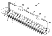
図1は本発明の液体吐出装置の第一の実施形態に係る液体吐出ヘッド10の模式的な斜視図である。液体吐出ヘッド10はA4サイズの被記録媒体の長辺長さより大きい300mmの印字幅を有しており、1ユニット当たり256〜2048個、またはそれ以上の吐出口で構成される複数の記録素子基板を直列に配置することで、1列の吐出口列が形成されている。
液体吐出ヘッド10は少なくとも、記録素子基板2と、フレキシブル配線基板11に電気的に接続された電気配線基板12と、インクの吐出制御のための電力と信号をそれぞれ供給する電力供給端子13と信号入力端子14と、を有している。電力供給端子13と信号入力端子14は液体吐出装置の印字制御回路(図示せず)と接続されている。インクはインクタンク(図示せず)から、毛細管現象によって、またはポンプによって、液体吐出ヘッド10の圧力室4へ供給される。他の実施形態では、液体吐出ヘッド10の上流側と下流側に2つのインクタンクを設け、一方のインクタンクから他方のインクタンクへインクを流すことにより、インクが圧力室4に供給される。
(First Embodiment)
FIG. 1 is a schematic perspective view of a liquid discharge head 10 according to a first embodiment of the liquid discharge device of the present invention. The liquid discharge head 10 has a print width of 300 mm, which is larger than the long side length of the A4 size recording medium, and has a plurality of recording element substrates composed of 256 to 2048 or more discharge ports per unit. Are arranged in series to form a row of discharge ports.
The liquid discharge head 10 includes at least a recording element board 2, an electrical wiring board 12 electrically connected to the flexible wiring board 11, and a power supply terminal 13 and a signal for supplying power and signals for ink discharge control, respectively. It has an input terminal 14. The power supply terminal 13 and the signal input terminal 14 are connected to a print control circuit (not shown) of the liquid discharge device. Ink is supplied from an ink tank (not shown) to the pressure chamber 4 of the liquid discharge head 10 by capillarity or by a pump. In another embodiment, two ink tanks are provided on the upstream side and the downstream side of the liquid ejection head 10, and ink is supplied to the pressure chamber 4 by flowing ink from one ink tank to the other ink tank.

図2は、記録素子基板2の一部を拡大して示す模式図である。図2(a)は記録素子基板2の平面図であり、内部の圧力室等を示している。図2(b)は図2(a)のa1−a2線に沿った断面図である。記録素子基板2は第1の面2aと、その反対面である第2の面2bと、を有しており、第1の面2aにインクに吐出のためのエネルギーを与える複数のエネルギー発生素子1を備えている。吐出口形成部材9はエネルギー発生素子1と対向する位置に複数の吐出口3を有している。吐出口3は600dpiの配置密度で配列されている。 FIG. 2 is a schematic view showing a part of the recording element substrate 2 in an enlarged manner. FIG. 2A is a plan view of the recording element substrate 2 and shows an internal pressure chamber and the like. FIG. 2B is a cross-sectional view taken along the line a1-a2 of FIG. 2A. The recording element substrate 2 has a first surface 2a and a second surface 2b opposite to the first surface 2a, and a plurality of energy generating elements that give energy for ejection to ink on the first surface 2a. It has 1. The discharge port forming member 9 has a plurality of discharge ports 3 at positions facing the energy generating element 1. The discharge ports 3 are arranged at an arrangement density of 600 dpi.

記録素子基板2と吐出口形成部材9との間に、記録素子基板2の長辺に沿って第1の方向Wに延びる2つの側壁8と、記録素子基板2の短辺と平行な方向(第2の方向D)に延びる複数の第1の隔壁7と、が設けられている。2つの側壁8と複数の第1の隔壁7は吐出口形成部材9と一体化され、吐出口形成部材9を記録素子基板2に固定している。記録素子基板2と吐出口形成部材9との間に、それぞれが一つのエネルギー発生素子1を備えた複数の圧力室4が形成されている。圧力室4は、記録素子基板2と、吐出口形成部材9と、互いに隣接する第1の隔壁7と、によって画定される。圧力室4はエネルギー発生素子1を含む空間であり、より広義には、エネルギー発生素子1を駆動した際に圧力が作用する領域である。本実施形態における圧力室4の大きさは、第1の方向Wにおいては互いに隣接する第1の隔壁7の間隔Wpに等しく、第2の方向Dにおいては第1の隔壁7の第2の方向Dの長さDsに等しい。また、圧力室4の第3の方向Hの大きさは記録素子基板2と吐出口形成部材9の間隔または側壁8の高さに等しい。第1の隔壁7の長さDsはエネルギー発生素子1の第2の方向Dにおける寸法Drより大きい。第1の隔壁7は第2の方向Dにおいて、エネルギー発生素子1よりも、次に述べる第1の連通孔5に近接している。この結果、インクは圧力室4の入口側の一部を第2の方向Dに流れた後に、エネルギー発生素子1の近傍に達する。圧力室4と第1の連通孔5の間には、圧力室4と第1の連通孔5に接続され、インクを圧力室4に供給する液体流路6が形成されている。 Between the recording element substrate 2 and the discharge port forming member 9, two side walls 8 extending in the first direction W along the long side of the recording element substrate 2 and a direction parallel to the short side of the recording element substrate 2 ( A plurality of first partition walls 7 extending in the second direction D) are provided. The two side walls 8 and the plurality of first partition walls 7 are integrated with the discharge port forming member 9, and the discharge port forming member 9 is fixed to the recording element substrate 2. A plurality of pressure chambers 4 each having one energy generating element 1 are formed between the recording element substrate 2 and the discharge port forming member 9. The pressure chamber 4 is defined by a recording element substrate 2, a discharge port forming member 9, and a first partition wall 7 adjacent to each other. The pressure chamber 4 is a space including the energy generating element 1, and in a broader sense, is a region in which pressure acts when the energy generating element 1 is driven. The size of the pressure chamber 4 in the present embodiment is equal to the distance Wp of the first partition walls 7 adjacent to each other in the first direction W, and the second direction of the first partition wall 7 in the second direction D. Equal to the length Ds of D. Further, the size of the pressure chamber 4 in the third direction H is equal to the distance between the recording element substrate 2 and the discharge port forming member 9 or the height of the side wall 8. The length Ds of the first partition wall 7 is larger than the dimension Dr in the second direction D of the energy generating element 1. The first partition wall 7 is closer to the first communication hole 5 described below than the energy generating element 1 in the second direction D. As a result, the ink flows through a part of the inlet side of the pressure chamber 4 in the second direction D and then reaches the vicinity of the energy generating element 1. A liquid flow path 6 connected to the pressure chamber 4 and the first communication hole 5 and supplying ink to the pressure chamber 4 is formed between the pressure chamber 4 and the first communication hole 5.

インクを供給する第1の連通孔5が、記録素子基板2を第1の面2aから第2の面2bまで貫通して設けられている。圧力室4は液体流路6を介して第1の連通孔5に接続されている。液体流路6内に、圧力室4に異物などが入るのを防ぐ柱状のフィルタ(図示せず)を設置してもよい。但し、圧力室4におけるインク流を乱さないようにフィルタの開口は最小限の大きさとし、少なくとも吐出口3の直径より小さい寸法とすることが望ましい。
インクタンク(図示せず)に貯蔵されたインクは、記録素子基板2の第2の面2b側に設けられた共通流路(図示せず)、第1の連通孔5及び液体流路6を介して圧力室4に供給される。エネルギー発生素子1は、記録素子基板2の内部に設けられた電気配線と、記録素子基板2の表面に設けられた端子とを介し、電気配線基板12と電気的に接続されている。エネルギー発生素子1は印字制御回路から入力されるパルス信号に基づいて発熱し、インクを沸騰させる。エネルギー発生素子1上でインクが発泡することで圧力室4に発泡圧力が生じ、その発泡圧力によってインクが吐出口3から第3の方向Hに吐出する。インクが吐出した後は、新たなインクが液体流路6を介して圧力室4に充填される。
A first communication hole 5 for supplying ink is provided so as to penetrate the recording element substrate 2 from the first surface 2a to the second surface 2b. The pressure chamber 4 is connected to the first communication hole 5 via the liquid flow path 6. A columnar filter (not shown) may be installed in the liquid flow path 6 to prevent foreign matter and the like from entering the pressure chamber 4. However, it is desirable that the opening of the filter is the minimum size so as not to disturb the ink flow in the pressure chamber 4, and the size is at least smaller than the diameter of the discharge port 3.
The ink stored in the ink tank (not shown) passes through a common flow path (not shown) provided on the second surface 2b side of the recording element substrate 2, a first communication hole 5, and a liquid flow path 6. It is supplied to the pressure chamber 4 via. The energy generating element 1 is electrically connected to the electric wiring board 12 via an electric wiring provided inside the recording element board 2 and a terminal provided on the surface of the recording element board 2. The energy generating element 1 generates heat based on a pulse signal input from the print control circuit to boil the ink. Foaming of ink on the energy generating element 1 causes foaming pressure in the pressure chamber 4, and the foaming pressure causes the ink to be ejected from the ejection port 3 in the third direction H. After the ink is ejected, new ink is filled in the pressure chamber 4 via the liquid flow path 6.

吐出口3から一定量のインク液滴が第3の方向Hに安定して吐出されるためには、エネルギー発生素子1上でインク流速の第1の方向Wにおけるばらつきが小さく、圧力室4内の発泡圧力が少なくともエネルギー発生素子1上で均一化されることが望ましい。このためには、圧力室4における第2の方向Dにおけるインク流速が第1の方向Wにおいてより均一であること、あるいはインク流速がゼロであることが望ましい。しかし、高速印刷時には、吐出口3からのインク吐出と圧力室4へのインク供給が高速で繰り返されるため、インク発泡時におけるエネルギー発生素子1上でのインク流速を一定に制御することが難しい。このため、圧力室4へのインク再充填時に、インク流速の乱れが発生しやすい。本実施形態では、圧力室4の形状を最適化することにより、インク流速の乱れを抑えることが可能となる。 In order for a constant amount of ink droplets to be stably ejected from the ejection port 3 in the third direction H, the variation of the ink flow velocity in the first direction W on the energy generating element 1 is small, and the inside of the pressure chamber 4 It is desirable that the foaming pressure of the ink is uniformed at least on the energy generating element 1. For this purpose, it is desirable that the ink flow rate in the second direction D in the pressure chamber 4 is more uniform in the first direction W, or that the ink flow rate is zero. However, during high-speed printing, ink ejection from the ejection port 3 and ink supply to the pressure chamber 4 are repeated at high speed, so that it is difficult to constantly control the ink flow velocity on the energy generating element 1 during ink foaming. Therefore, when the pressure chamber 4 is refilled with ink, the ink flow velocity is likely to be disturbed. In the present embodiment, by optimizing the shape of the pressure chamber 4, it is possible to suppress the disturbance of the ink flow rate.

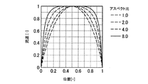
図3は、圧力室4の第1の方向Wにおける位置とインクの流速分布の関係を、圧力室4のアスペクト比をパラメータとして示している。インクの流速分布は、吐出口3の中心を通り第1の面2aと直交し第1の方向Wと平行な圧力室4の断面における、圧力室4の第2の方向Dのインク流速の、第1の方向Wでの分布である。アスペクト比は、圧力室4の高さHpに対する、第1の方向Wにおいて互いに隣接する第1の隔壁7の離間距離Wpの比(Wp/Hp)である。圧力室4の高さは第3の方向Hにおける圧力室4の寸法を意味し、第3の方向Hにおける記録素子基板2と吐出口形成部材9との間隔または側壁8の高さに等しい。横軸は圧力室4の第1の方向Wにおける位置を規準化して示しており、縦軸は第2の方向Dにおけるインク流速を、最大値を1として規準化して示している。圧力室4のアスペクト比が大きいほどインクと壁面の間に働く摩擦の影響が大きくなり、その結果、圧力室4における流速分布が第1の方向Wに均一化される範囲が拡大する。つまり、圧力室4で第1の方向Wにより均一なインク流速分布を得るためには、より高アスペクト比の圧力室4が望ましいことが分かる。 FIG. 3 shows the relationship between the position of the pressure chamber 4 in the first direction W and the flow velocity distribution of the ink, using the aspect ratio of the pressure chamber 4 as a parameter. The flow velocity distribution of the ink is the flow velocity distribution of the ink in the second direction D of the pressure chamber 4 in the cross section of the pressure chamber 4 passing through the center of the discharge port 3 and orthogonal to the first surface 2a and parallel to the first direction W. It is a distribution in the first direction W. The aspect ratio is the ratio (Wp / Hp) of the separation distance Wp of the first partition walls 7 adjacent to each other in the first direction W with respect to the height Hp of the pressure chamber 4. The height of the pressure chamber 4 means the dimension of the pressure chamber 4 in the third direction H, and is equal to the distance between the recording element substrate 2 and the discharge port forming member 9 or the height of the side wall 8 in the third direction H. The horizontal axis shows the position of the pressure chamber 4 in the first direction W as a standard, and the vertical axis shows the ink flow velocity in the second direction D as a standard with a maximum value of 1. The larger the aspect ratio of the pressure chamber 4, the greater the influence of friction acting between the ink and the wall surface, and as a result, the range in which the flow velocity distribution in the pressure chamber 4 is made uniform in the first direction W is expanded. That is, it can be seen that the pressure chamber 4 having a higher aspect ratio is desirable in order to obtain a uniform ink flow velocity distribution in the first direction W in the pressure chamber 4.

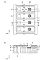
図4は、吐出口Aを備えた圧力室4におけるインクの流れを模式的に示している。ここでは吐出口Aの近傍の他の吐出口3からはインクが吐出しないと仮定する。図4(a)は記録素子基板2の平面図であり、吐出口Aからインクが吐出した後に圧力室4に供給されるインクの流れを模式的に示している。図4(b)及び(c)は、図4(a)のb1−b2線に沿った圧力室4の断面におけるインクの第2の方向Dの流速を、第1の方向Wの位置の関数として模式的に示している。図4(b)は圧力室4のアスペクト比が2.0の場合を、図4(c)は4.0の場合を示している。 FIG. 4 schematically shows the flow of ink in the pressure chamber 4 provided with the discharge port A. Here, it is assumed that ink is not ejected from the other ejection ports 3 in the vicinity of the ejection port A. FIG. 4A is a plan view of the recording element substrate 2, and schematically shows the flow of ink supplied to the pressure chamber 4 after the ink is ejected from the ejection port A. 4 (b) and 4 (c) show the flow velocity of the ink in the second direction D in the cross section of the pressure chamber 4 along the line b1-b2 of FIG. 4 (a) as a function of the position of the first direction W. It is schematically shown as. FIG. 4B shows the case where the aspect ratio of the pressure chamber 4 is 2.0, and FIG. 4C shows the case where the aspect ratio is 4.0.

吐出口Aからインクが吐出した後、圧力室4には第1の連通孔5から液体流路6を介してインクが再充填される。図4(a)に示す構成では、圧力室4が第1の隔壁7によって完全に仕切られていないため、吐出口Aと対向する第1の連通孔5だけでなく、その連通孔と隣接する第1の連通孔5からも、吐出口Aを備える圧力室4にインクが再充填される。そのため、圧力室4の入口では複数の第1の連通孔5から流入するインクの混合流が発生している。図4(b)に示す、アスペクト比が小さい圧力室4の場合には、圧力室4におけるインク流速のばらつきが大きく、特にエネルギー発生素子1上で流速分布のばらつきが大きい。一方、図4(c)に示す、アスペクト比が大きい圧力室4の場合には、第1の方向Wのインクの流速分布がより平坦化されており、特にエネルギー発生素子1上で流速分布のばらつきは相対的に小さく、ほぼ均一化されている。このため、隣接するエネルギー発生素子1の発泡圧力の影響が不連続的に発生する場合にも、混合流によるインク流速の時間的ゆらぎが緩和され、圧力室4内のインク流速分布をより均一化することが可能となる。 After the ink is discharged from the discharge port A, the pressure chamber 4 is refilled with the ink from the first communication hole 5 through the liquid flow path 6. In the configuration shown in FIG. 4A, since the pressure chamber 4 is not completely partitioned by the first partition wall 7, not only the first communication hole 5 facing the discharge port A but also the communication hole adjacent to the first communication hole 5 is adjacent to the first communication hole 5. Ink is also refilled from the first communication hole 5 into the pressure chamber 4 provided with the discharge port A. Therefore, at the inlet of the pressure chamber 4, a mixed flow of ink flowing in from the plurality of first communication holes 5 is generated. In the case of the pressure chamber 4 having a small aspect ratio shown in FIG. 4B, the variation in the ink flow velocity in the pressure chamber 4 is large, and the variation in the flow velocity distribution is particularly large on the energy generating element 1. On the other hand, in the case of the pressure chamber 4 having a large aspect ratio shown in FIG. 4C, the flow velocity distribution of the ink in the first direction W is more flattened, and the flow velocity distribution is particularly on the energy generating element 1. The variation is relatively small and almost uniform. Therefore, even when the influence of the foaming pressure of the adjacent energy generating element 1 occurs discontinuously, the temporal fluctuation of the ink flow velocity due to the mixed flow is alleviated, and the ink flow velocity distribution in the pressure chamber 4 becomes more uniform. It becomes possible to do.

相対的に高アスペクト比の圧力室においては、より大きな壁面抵抗がインクに作用する。圧力室4の大きな壁面抵抗はインク流の整流作用を生じさせ、圧力室4に流入するインクの流速分布をより均一化する。高速印刷時には連続してインク液滴の吐出が行われるため、圧力室4内のインク流速がゼロとなる前に、次のインク液滴が吐出される場合がある。その場合にも、圧力室4のエネルギー発生素子1上で、インクの流速分布が第1の方向Wに均一化された広い領域が確保されるため、インク液滴の吐出速度と吐出方向を安定化させることが可能となる。
図4では、吐出口Aだけからインクが吐出すると仮定しているが、実際には複数の吐出口3からインク液滴が次々に吐出する。隣接する吐出口3からインクが吐出する際の圧力の影響で、圧力室4に供給されるインクの流速分布はさらに乱れ不安定化する。しかし、本実施形態の高アスペクト比の圧力室4では、圧力室4に供給されたインク流が整流され、エネルギー発生素子1上でより均一なインク流速分布が実現される。
In a pressure chamber with a relatively high aspect ratio, a larger wall resistance acts on the ink. The large wall resistance of the pressure chamber 4 causes a rectifying action of the ink flow, and makes the flow velocity distribution of the ink flowing into the pressure chamber 4 more uniform. Since ink droplets are continuously ejected during high-speed printing, the next ink droplet may be ejected before the ink flow velocity in the pressure chamber 4 becomes zero. Even in that case, since a wide region in which the flow velocity distribution of the ink is uniformized in the first direction W is secured on the energy generating element 1 of the pressure chamber 4, the ejection speed and the ejection direction of the ink droplets are stable. It becomes possible to make it.
In FIG. 4, it is assumed that the ink is ejected only from the ejection port A, but in reality, the ink droplets are ejected one after another from the plurality of ejection ports 3. The flow velocity distribution of the ink supplied to the pressure chamber 4 is further disturbed and unstable due to the influence of the pressure when the ink is ejected from the adjacent ejection port 3. However, in the pressure chamber 4 having a high aspect ratio of the present embodiment, the ink flow supplied to the pressure chamber 4 is rectified, and a more uniform ink flow velocity distribution is realized on the energy generating element 1.

次に、インク液滴を安定して吐出するために必要となる圧力室4のアスペクト比について、図2の構成を用いて説明する。液体吐出ヘッド10の主要部の寸法は以下のとおりである。
エネルギー発生素子1の長さDr:22μm
エネルギー発生素子1の幅Wr:18μm
吐出口3の直径R:20μm
圧力室4の幅Wp:37.3μm
第1の連通孔5の断面長さDh:19μm
第1の連通孔5の断面幅Wh:19μm
液体流路6及び圧力室4の高さ(側壁8の高さ)Hp:9μm
第1の隔壁7の長さDs:40μm
第1の隔壁7の幅Ws:5μm
両側の側壁8の間隔Di:100μm
吐出口形成部材9の厚み:7μm
インク粘度は3cP、インク吐出量(一つのインク液滴の大きさ)は2pLとする。
Next, the aspect ratio of the pressure chamber 4 required for stable ejection of ink droplets will be described with reference to the configuration of FIG. The dimensions of the main part of the liquid discharge head 10 are as follows.
Length of energy generating element 1 Dr: 22 μm
Width of energy generating element 1 Wr: 18 μm
Diameter R of discharge port 3: 20 μm
Width Wp of pressure chamber 4: 37.3 μm
Cross-sectional length of the first communication hole 5 Dh: 19 μm
Cross-sectional width Wh of the first communication hole 5: 19 μm
Height of liquid flow path 6 and pressure chamber 4 (height of side wall 8) Hp: 9 μm
Length of first partition wall 7 Ds: 40 μm
Width Ws of the first partition wall 7: 5 μm
Spacing between side walls 8 on both sides Di: 100 μm
Thickness of discharge port forming member 9: 7 μm
The ink viscosity is 3 cP, and the ink ejection amount (the size of one ink droplet) is 2 pL.

インクの安定吐出のためには、エネルギー発生素子1の幅(Wr=17μm)上に実質的に均一とみなせるインク流速分布が得られていることが必要となる。
安定吐出のために必要となるインク流速分布の均一性を表す目安値として「等価流速域」を用いる。「等価流速域」は、圧力室4の内部における、図3に示す規準化された流速が0.95以上となる領域の幅と定義する。すなわち、「等価流速域」の長さは吐出口3の中心を通り第1の面2aと直交し第1の方向Wと平行な圧力室4の断面において、インクの流速が最大値の95%以上となる範囲の第1の方向Wにおける長さである。「等価流速域」の長さがエネルギー発生素子1の幅Wrより大きければ、エネルギー発生素子1上で略均一とみなせるインク流速分布が得られることになる。なお、インク流速分布は、図4(b),(c)に示すように第1の方向Wに関しほぼ対称形と考えられる。よって、「等価流速域」の長さがエネルギー発生素子1の幅Wrより大きければ、エネルギー発生素子1の全幅で略均一とみなせるインク流速分布が得られる。
For stable ink ejection, it is necessary to obtain an ink flow velocity distribution that can be regarded as substantially uniform on the width (Wr = 17 μm) of the energy generating element 1.
The "equivalent flow velocity range" is used as a guideline value indicating the uniformity of the ink flow velocity distribution required for stable ejection. The "equivalent flow velocity region" is defined as the width of the region inside the pressure chamber 4 where the standardized flow velocity shown in FIG. 3 is 0.95 or more. That is, the length of the "equivalent flow velocity region" is 95% of the maximum value of the ink flow velocity in the cross section of the pressure chamber 4 passing through the center of the discharge port 3, orthogonal to the first surface 2a, and parallel to the first direction W. It is the length in the first direction W of the above range. If the length of the "equivalent flow velocity region" is larger than the width Wr of the energy generating element 1, an ink flow velocity distribution that can be regarded as substantially uniform on the energy generating element 1 can be obtained. The ink flow velocity distribution is considered to be substantially symmetrical with respect to the first direction W as shown in FIGS. 4 (b) and 4 (c). Therefore, if the length of the "equivalent flow velocity region" is larger than the width Wr of the energy generating element 1, an ink flow velocity distribution that can be regarded as substantially uniform over the entire width of the energy generating element 1 can be obtained.

図5は圧力室4のアスペクト比と等価流速域との関係を示している。図2の構成において、エネルギー発生素子1の幅Wrは18μm、圧力室4の幅Wpは37.3μmであるため、安定吐出のために必要となる等価流速域の下限値はWr/Wp=0.48である。記録素子基板2の製作工程における公差を考慮し、等価流速域の下限値をWr/Wp=0.50とする。図5を参照すると、圧力室4のアスペクト比が4.0以上のとき等価流速域が0.51以上となり、エネルギー発生素子1上で略均一とみなせるインク流速分布が得られる。これより、等価流速域の長さがエネルギー発生素子1の幅Wrより大きくなるためには、圧力室4のアスペクト比が4以上(4.0以上)であればよいことになる。
安定吐出のために必要となる等価流速域はエネルギー発生素子1の幅Wrにより変わり得るが、圧力室4は所望のインク吐出量を得るための最低限の大きさを必要とする。1pLのインク吐出量を得るためには、これに相当する10μmx10μmx10μm程度のインク体積を圧力室4に確保することが必要である。上記アスペクト比を考慮すると、圧力室4の高さは10μm以下であることが望ましい。等価流速域を0.5程度とし、圧力室4のアスペクト比の下限を4.0とすることによって、必要となるエネルギー発生素子1の幅Wrに対して、インク流速分布が均一化される圧力室4の幅Wpを設定することが可能となる。このように圧力室4のアスペクト比が4.0以上であれば、圧力室4における液体の流速分布のばらつきが減少し、着弾精度を向上させることができる。尚、流速分布に関しては上記アスペクト比の観点の他に、液体の粘度等の液体の物性や環境温度等のパラメータによっても変動し得る。しかながら流速分布のばらつきに関しては上述したアスペクト比に関する観点が支配的であり、このアスペクト比の影響に比べれば液体の物性や環境温度等のパラメータは実質的に無視できる。
FIG. 5 shows the relationship between the aspect ratio of the pressure chamber 4 and the equivalent flow velocity region. In the configuration of FIG. 2, since the width Wr of the energy generating element 1 is 18 μm and the width Wp of the pressure chamber 4 is 37.3 μm, the lower limit of the equivalent flow velocity range required for stable discharge is Wr / Wp = 0. It is .48. Considering the tolerance in the manufacturing process of the recording element substrate 2, the lower limit value of the equivalent flow velocity region is set to Wr / Wp = 0.50. Referring to FIG. 5, when the aspect ratio of the pressure chamber 4 is 4.0 or more, the equivalent flow velocity region becomes 0.51 or more, and an ink flow velocity distribution that can be regarded as substantially uniform on the energy generating element 1 can be obtained. From this, in order for the length of the equivalent flow velocity region to be larger than the width Wr of the energy generating element 1, the aspect ratio of the pressure chamber 4 should be 4 or more (4.0 or more).
The equivalent flow velocity range required for stable ejection can vary depending on the width Wr of the energy generating element 1, but the pressure chamber 4 requires a minimum size for obtaining a desired ink ejection amount. In order to obtain an ink ejection amount of 1 pL, it is necessary to secure an ink volume of about 10 μmx 10 μmx 10 μm corresponding to this in the pressure chamber 4. Considering the above aspect ratio, it is desirable that the height of the pressure chamber 4 is 10 μm or less. By setting the equivalent flow velocity range to about 0.5 and the lower limit of the aspect ratio of the pressure chamber 4 to 4.0, the pressure at which the ink flow velocity distribution is made uniform with respect to the required width Wr of the energy generating element 1. It is possible to set the width Wp of the room 4. When the aspect ratio of the pressure chamber 4 is 4.0 or more as described above, the variation in the flow velocity distribution of the liquid in the pressure chamber 4 is reduced, and the landing accuracy can be improved. The flow velocity distribution may vary depending on the physical properties of the liquid such as the viscosity of the liquid and parameters such as the environmental temperature, in addition to the viewpoint of the aspect ratio. However, regarding the variation in the flow velocity distribution, the above-mentioned viewpoint regarding the aspect ratio is dominant, and compared to the influence of this aspect ratio, parameters such as the physical properties of the liquid and the environmental temperature can be substantially ignored.

以下、インク液滴の安定吐出のために、さらに望ましい液体吐出ヘッドの形態について説明する。なお、図6〜13は図2と同様の図であり、(a)は記録素子基板2の平面図を、(b)は(a)のa1−a2線に沿った断面図を示している。 Hereinafter, a more desirable form of the liquid ejection head will be described for stable ejection of ink droplets. 6 to 13 are the same views as those in FIG. 2, where FIG. 6A shows a plan view of the recording element substrate 2, and FIG. 6B shows a cross-sectional view taken along line a1-a2 of FIG. ..

図2に示す液体吐出ヘッド10では、エネルギー発生素子1が600dpiの配置密度で配置され、第1の連通孔5がエネルギー発生素子列の片側に、エネルギー発生素子1に沿って600dpiの配置密度で配置されている。エネルギー発生素子1と第1の連通孔5は等ピッチで同数配置され、かつ、エネルギー発生素子1の中心とこれと対向する第1の連通孔5の中心とを結ぶ直線が第2の方向Dと平行である。複数の第1の連通孔5からなる連通孔列の第1の方向Wにおける中心位置が、複数の圧力室4からなる圧力室列の第1の方向Wにおける中心位置と、第1の方向Wにおいて一致している。これにより、圧力室4に流入するインク流は第2の方向Dの速度成分が多くなり、圧力室4内におけるインク流速分布の乱れを最小限に抑えることができる。
圧力室4の流路断面積(第2の方向Dと直交する断面における流路面積)は第1の連通孔5の最少流路断面積(第3の方向Hと直交する断面における最少流路面積)より小さい。これによって圧力室4のインク流速が第1の連通孔5のインク流速よりも大きくなるため、圧力室4におけるインクの滞留領域が小さくなり、さらにインク流速分布の均一化を図ることができる。本構成は、記録素子基板2の製造プロセスの制約や隣接する吐出口3間での圧力伝搬の防止のために、インク流路に屈曲部または行き止まり部を設ける場合にも効果的である。
In the liquid discharge head 10 shown in FIG. 2, the energy generating element 1 is arranged at an arrangement density of 600 dpi, and the first communication hole 5 is arranged on one side of the energy generating element row at an arrangement density of 600 dpi along the energy generating element 1. Have been placed. The energy generating element 1 and the first communication hole 5 are arranged in the same number at equal pitches, and a straight line connecting the center of the energy generating element 1 and the center of the first communication hole 5 facing the center of the energy generating element 1 is the second direction D. Is parallel to. The center position of the communication hole row composed of the plurality of first communication holes 5 in the first direction W is the center position of the pressure chamber row consisting of the plurality of pressure chambers 4 in the first direction W and the first direction W. Are in agreement. As a result, the ink flow flowing into the pressure chamber 4 has a large velocity component in the second direction D, and the disturbance of the ink flow velocity distribution in the pressure chamber 4 can be minimized.
The flow path cross-sectional area of the pressure chamber 4 (the flow path area in the cross section orthogonal to the second direction D) is the minimum flow path cross-sectional area of the first communication hole 5 (the minimum flow path in the cross section orthogonal to the third direction H). Area) smaller. As a result, the ink flow velocity in the pressure chamber 4 becomes larger than the ink flow velocity in the first communication hole 5, so that the ink retention region in the pressure chamber 4 becomes smaller, and the ink flow velocity distribution can be made uniform. This configuration is also effective when a bent portion or a dead end portion is provided in the ink flow path in order to restrict the manufacturing process of the recording element substrate 2 and prevent pressure propagation between adjacent ejection ports 3.

図6は本実施形態の液体吐出ヘッド10の変形例を示している。互いに隣接する第1の連通孔5の間に第2の隔壁107が設けられている。第2の隔壁107は第1の隔壁7と一体化されているが、第1の隔壁7から分離されていてもよい。図7は本実施形態の液体吐出ヘッド10の他の変形例を示している。一体化された第1の隔壁7と第2の隔壁107(隔壁207)は2つの側壁8とともに、第1の連通孔5及び圧力室4を他の第1の連通孔5及び圧力室4から完全に仕切っている。液体流路6と圧力室4は同じ流路幅Wpと流路高さHpを有しており、いずれもアスペクト比Wp/Hp≧4の条件を満たしている。これらの変形例は、隣接する圧力室4でのインク吐出による圧力振動や、第1の連通孔5からのインク供給量のばらつきが必要な吐出精度に対して問題となる場合に有効である。 FIG. 6 shows a modified example of the liquid discharge head 10 of the present embodiment. A second partition wall 107 is provided between the first communication holes 5 adjacent to each other. Although the second partition wall 107 is integrated with the first partition wall 7, it may be separated from the first partition wall 7. FIG. 7 shows another modification of the liquid discharge head 10 of the present embodiment. The integrated first partition wall 7 and the second partition wall 107 (partition wall 207), together with the two side walls 8, allow the first communication hole 5 and the pressure chamber 4 from the other first communication hole 5 and the pressure chamber 4. It is completely partitioned. The liquid flow path 6 and the pressure chamber 4 have the same flow path width Wp and flow path height Hp, and both satisfy the condition of the aspect ratio Wp / Hp ≧ 4. These modifications are effective when there is a problem with respect to pressure vibration due to ink ejection in the adjacent pressure chamber 4 and ejection accuracy in which variation in the amount of ink supplied from the first communication hole 5 is required.

図8は本実施形態の液体吐出ヘッド10の他の変形例を示している。両側の隔壁207から液体流路6に突き出す2つの突起18が設けられている。2つの突起18は好ましくは同じ形状を有し、第2の方向Dに関して同じ位置に設けられている。突起18はエネルギー発生素子1と第1の連通孔5との間に位置している。突起18は圧力室4で発生した吐出圧力が第1の連通孔5に向けて拡散することを抑制する。圧力室4はアスペクト比Wp/Hp≧4の条件を満たしている。好ましくは、最も狭い流路幅Wdとなる2つの突起18間でアスペクト比Wd/Hp≧4が満たされることで、より均一なインク流速分布が実現される。 FIG. 8 shows another modification of the liquid discharge head 10 of the present embodiment. Two protrusions 18 protruding from the partition walls 207 on both sides into the liquid flow path 6 are provided. The two protrusions 18 preferably have the same shape and are provided at the same position with respect to the second direction D. The protrusion 18 is located between the energy generating element 1 and the first communication hole 5. The protrusion 18 suppresses the discharge pressure generated in the pressure chamber 4 from diffusing toward the first communication hole 5. The pressure chamber 4 satisfies the condition that the aspect ratio Wp / Hp ≧ 4. Preferably, a more uniform ink flow velocity distribution is realized by satisfying the aspect ratio Wd / Hp ≧ 4 between the two protrusions 18 having the narrowest flow path width Wd.

図9は本実施形態の液体吐出ヘッド10の他の変形例を示している。液体流路6に段差21が形成されており、液体流路6の高さが圧力室4の入口よりも第1の連通孔5の近傍で大きくなっている。段差の形状はこれに限定されず、第3の方向Hにおける液体流路6の高さが液体流路6に沿った2以上の位置で互いに異なっていればよい。また、段差の代わりになめらかな曲面が設けられてもよい。図9に示す液体流路6はより多くのインクを圧力室4に供給できるが、インクの流れが乱されやすい。しかし、圧力室4がアスペクト比Wp/Hp≧4の条件を満たすことで、エネルギー発生素子1上でより均一なインク流速分布が実現される。 FIG. 9 shows another modification of the liquid discharge head 10 of the present embodiment. A step 21 is formed in the liquid flow path 6, and the height of the liquid flow path 6 is larger in the vicinity of the first communication hole 5 than the inlet of the pressure chamber 4. The shape of the step is not limited to this, and the heights of the liquid flow paths 6 in the third direction H may be different from each other at two or more positions along the liquid flow path 6. Further, a smooth curved surface may be provided instead of the step. The liquid flow path 6 shown in FIG. 9 can supply more ink to the pressure chamber 4, but the ink flow is likely to be disturbed. However, when the pressure chamber 4 satisfies the condition of the aspect ratio Wp / Hp ≧ 4, a more uniform ink flow velocity distribution is realized on the energy generating element 1.

図10は本実施形態の液体吐出ヘッド10の他の変形例を示している。互いに隣接する第1の連通孔5の間に2つの第2の隔壁307a,307bが設けられている。第1の連通孔5の間に設けられる第2の隔壁307a,307bの数はこれに限定されない。第2の隔壁307a,307bは第1の隔壁7から分離しているが、第1の隔壁7と一体化されていてもよい。吐出口形成部材9を第1の隔壁7と側壁8だけでなく、第2の隔壁307a,307bでも支持することができるため、外力や膨潤に対する吐出口形成部材9の変形を抑えることが可能となる。本実施形態でも流路幅Wpと流路高さHpはアスペクト比Wp/Hp≧4の条件を満たしている。 FIG. 10 shows another modification of the liquid discharge head 10 of the present embodiment. Two second partition walls 307a and 307b are provided between the first communication holes 5 adjacent to each other. The number of the second partition walls 307a and 307b provided between the first communication holes 5 is not limited to this. Although the second partition walls 307a and 307b are separated from the first partition wall 7, they may be integrated with the first partition wall 7. Since the discharge port forming member 9 can be supported not only by the first partition wall 7 and the side wall 8 but also by the second partition walls 307a and 307b, it is possible to suppress the deformation of the discharge port forming member 9 due to external force or swelling. Become. Also in this embodiment, the flow path width Wp and the flow path height Hp satisfy the condition of the aspect ratio Wp / Hp ≧ 4.

図11は本実施形態の液体吐出ヘッド10の他の変形例を示している。第1の連通孔5の配列間隔はエネルギー発生素子1の配列間隔より大きく、1つの第1の連通孔5に複数の(本実施形態では2つの)圧力室4が割り当てられている。本変形例では、第1の連通孔5を形成するためのプロセス解像度の制限よりも高い解像度(配置密度)で吐出口3を形成することが可能となる。第1の連通孔5から供給されたインクは2つの圧力室4に斜め方向に流入するため、圧力室4内のインク流速分布の乱れが発生しやすい。しかし、圧力室4のアスペクト比をWp/Hp≧4とすることで、インク流速分布の均一化を実現できる。 FIG. 11 shows another modification of the liquid discharge head 10 of the present embodiment. The arrangement interval of the first communication holes 5 is larger than the arrangement interval of the energy generating element 1, and a plurality of (two in this embodiment) pressure chambers 4 are assigned to one first communication hole 5. In this modification, it is possible to form the discharge port 3 with a resolution (arrangement density) higher than the process resolution limit for forming the first communication hole 5. Since the ink supplied from the first communication hole 5 flows into the two pressure chambers 4 in an oblique direction, the ink flow velocity distribution in the pressure chamber 4 is likely to be disturbed. However, by setting the aspect ratio of the pressure chamber 4 to Wp / Hp ≧ 4, it is possible to realize uniform ink flow velocity distribution.

以上述べた本実施形態とその変形例に係るライン型の液体吐出ヘッド10においては、共通のインクタンクから長尺の液体吐出ヘッド10にインクが供給される。このため、インクタンクから第1の連通孔5までの流路長が第1の連通孔5によって大きく異なり、第1の連通孔5に供給されるインク圧力に差が生じやすい。しかし、圧力室4のアスペクト比をWp/Hp≧4とすることで、多数の吐出口3を有するライン型の液体吐出ヘッドにおいても、インク流速分布を均一化し、インク液滴の着弾位置のばらつきを抑えることができる。 In the line-type liquid ejection head 10 according to the present embodiment and its modification described above, ink is supplied from a common ink tank to the long liquid ejection head 10. Therefore, the flow path length from the ink tank to the first communication hole 5 differs greatly depending on the first communication hole 5, and the ink pressure supplied to the first communication hole 5 tends to differ. However, by setting the aspect ratio of the pressure chamber 4 to Wp / Hp ≧ 4, the ink flow velocity distribution is made uniform even in the line-type liquid ejection head having a large number of ejection ports 3, and the landing position of the ink droplets varies. Can be suppressed.

(第二の実施形態)
本実施形態の液体吐出ヘッドの基本的な構成は第一の実施形態と同様であり、特徴的な構成についてのみ説明する。
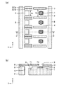
図12を参照すると、液体吐出ヘッド10は、圧力室4に関し第1の連通孔5の反対側に、記録素子基板2を貫通し、圧力室4と連通する第2の連通孔205を有している。エネルギー発生素子1は600dpiの配置密度で配置されており、エネルギー発生素子1の両側に第1の連通孔5と第2の連通孔205がそれぞれ600dpiの配置密度で配置されている。液体吐出ヘッド10は430mmの印字幅を有するライン型の液体吐出ヘッドであり、1ユニット当たり256〜2048個、またはそれ以上の吐出口3で構成される複数の記録素子基板2が直列に配置されている。
圧力室4の第1の方向Wにおける両側には第1の隔壁7が設けられ、第1の方向Wに互いに隣接する第1の連通孔5間及び第2の連通孔205間には第2の隔壁107が設けられている。第1の隔壁7と第2の隔壁107は第1の連通孔5から第2の連通孔205まで連続するように一体化されているが、分離されていてもよい。本実施形態の液体吐出ヘッド10の主要部の寸法は以下のとおりである。
エネルギー発生素子1の長さDr:20μm
エネルギー発生素子1の幅Wr:15μm
吐出口3の直径R:20μm
圧力室4の幅Wp:37.3μm
連通孔5,205の断面長さDh:20μm
連通孔5,205の断面幅Wh:20μm
液体流路6及び圧力室4の高さ(側壁8の高さ)Hp:8μm
隔壁の長さ(隔壁7,107を合わせた全長)Ds:140μm
隔壁7,107の幅Ws:5μm
両側の側壁8の間隔Di:160μm
吐出口形成部材9の厚み:6μm
(Second embodiment)
The basic configuration of the liquid discharge head of the present embodiment is the same as that of the first embodiment, and only the characteristic configuration will be described.
Referring to FIG. 12, the liquid discharge head 10 has a second communication hole 205 that penetrates the recording element substrate 2 and communicates with the pressure chamber 4 on the opposite side of the first communication hole 5 with respect to the pressure chamber 4. ing. The energy generating element 1 is arranged at an arrangement density of 600 dpi, and the first communication hole 5 and the second communication hole 205 are arranged on both sides of the energy generating element 1 at an arrangement density of 600 dpi. The liquid discharge head 10 is a line-type liquid discharge head having a printing width of 430 mm, and a plurality of recording element substrates 2 composed of 256 to 2048 or more discharge ports 3 per unit are arranged in series. ing.
First partition walls 7 are provided on both sides of the pressure chamber 4 in the first direction W, and a second partition wall 7 is provided between the first communication holes 5 and 205 between the first communication holes 5 adjacent to each other in the first direction W. The partition wall 107 is provided. The first partition wall 7 and the second partition wall 107 are integrated so as to be continuous from the first communication hole 5 to the second communication hole 205, but may be separated. The dimensions of the main part of the liquid discharge head 10 of the present embodiment are as follows.
Length of energy generating element 1 Dr: 20 μm
Width of energy generating element 1 Wr: 15 μm
Diameter R of discharge port 3: 20 μm
Width Wp of pressure chamber 4: 37.3 μm
Cross-sectional length of communication holes 5,205 Dh: 20 μm
Cross-sectional width Wh of communication holes 5,205: 20 μm
Height of liquid flow path 6 and pressure chamber 4 (height of side wall 8) Hp: 8 μm
Partition length (total length of partition walls 7 and 107 combined) Ds: 140 μm
Width Ws of partition walls 7,107: 5 μm
Spacing between side walls 8 on both sides Di: 160 μm
Thickness of discharge port forming member 9: 6 μm

本実施形態の液体吐出ヘッド10においては、圧力室4のアスペクト比Wp/Hpを4.66以上とすることで等価流速域の下限値を確保することができる。また、圧力室4の両側に第1の連通孔5と第2の連通孔205が設けられ、圧力室4の両側からインクが供給される。このため、吐出口3の両側におけるインクの流速分布の対称性が向上し、インクが第2の方向Dに沿って安定して流れる。これらの効果によりインク液滴の着弾精度をさらに高めることができる。また、本実施形態の液体吐出ヘッド10は双方向からインクが供給されるため、高速駆動が可能である。
さらに本実施形態では、液体流路6の最小高さが吐出口3の最大径よりも小さくされている。このため、仮に液体流路6内に異物が発生したり混入したりした場合でも、吐出口3の最大径より大きな異物が圧力室4に供給されることはなく、吐出口3への異物の詰まりによる不吐出を防止し、インク液滴の着弾位置のばらつきを抑えることができる。
In the liquid discharge head 10 of the present embodiment, the lower limit value of the equivalent flow velocity region can be secured by setting the aspect ratio Wp / Hp of the pressure chamber 4 to 4.66 or more. Further, a first communication hole 5 and a second communication hole 205 are provided on both sides of the pressure chamber 4, and ink is supplied from both sides of the pressure chamber 4. Therefore, the symmetry of the flow velocity distribution of the ink on both sides of the ejection port 3 is improved, and the ink flows stably along the second direction D. Due to these effects, the landing accuracy of the ink droplets can be further improved. Further, since the liquid ejection head 10 of the present embodiment is supplied with ink from both directions, it can be driven at high speed.
Further, in the present embodiment, the minimum height of the liquid flow path 6 is made smaller than the maximum diameter of the discharge port 3. Therefore, even if foreign matter is generated or mixed in the liquid flow path 6, the foreign matter larger than the maximum diameter of the discharge port 3 is not supplied to the pressure chamber 4, and the foreign matter to the discharge port 3 is not supplied. It is possible to prevent non-ejection due to clogging and suppress variations in the landing position of ink droplets.

(第三の実施形態)
本実施形態の液体吐出ヘッド10の基本的な構成は第二の実施形態と同様であり、特徴的な構成についてのみ説明する。
図13は本実施形態の液体吐出ヘッド10の記録素子基板2の構成を示している。本実施形態の液体吐出ヘッド10では圧力室4内のインクが第1の連通孔105から第2の連通孔305に向けて循環する。このため、本実施形態の液体吐出ヘッド10を備える液体吐出装置は、圧力室内のインクを圧力室の外部との間で循環する手段を有している。本実施形態では、インクをインクタンクと液体吐出ヘッド10との間で循環させているが、液体吐出ヘッド10の上流側と下流側に2つのタンクを設け、一方のタンクから他方のタンクへインクを流すことで圧力室4内のインクを循環させてもよい。
本実施形態の液体吐出ヘッド10の主要部の寸法は以下のとおりである。
連通孔の断面長さDh:20μm
連通孔の幅Wh:50μm
第1の隔壁7の長さDs:80μm
第1の隔壁7の幅Ws:5μm
第2の隔壁307a,307b,407a,407bの長さDs:30μm
第2の隔壁307a,307b,407a,407bの幅Ws:4μm
両側の側壁8の間隔Di:160μm
(Third embodiment)
The basic configuration of the liquid discharge head 10 of the present embodiment is the same as that of the second embodiment, and only the characteristic configuration will be described.
FIG. 13 shows the configuration of the recording element substrate 2 of the liquid discharge head 10 of the present embodiment. In the liquid discharge head 10 of the present embodiment, the ink in the pressure chamber 4 circulates from the first communication hole 105 to the second communication hole 305. Therefore, the liquid discharge device including the liquid discharge head 10 of the present embodiment has a means for circulating the ink in the pressure chamber to the outside of the pressure chamber. In the present embodiment, the ink is circulated between the ink tank and the liquid discharge head 10, but two tanks are provided on the upstream side and the downstream side of the liquid discharge head 10, and ink is provided from one tank to the other tank. The ink in the pressure chamber 4 may be circulated by flowing the ink.
The dimensions of the main part of the liquid discharge head 10 of the present embodiment are as follows.
Cross-sectional length of communication hole Dh: 20 μm
Width of communication hole Wh: 50 μm
Length of first partition wall 7 Ds: 80 μm
Width Ws of the first partition wall 7: 5 μm
Lengths of the second partition walls 307a, 307b, 407a, 407b Ds: 30 μm
Width Ws of the second partition wall 307a, 307b, 407a, 407b: 4 μm
Spacing between side walls 8 on both sides Di: 160 μm

第1の連通孔105の間には2つの第2の隔壁307a,307bが設けられ、第2の連通孔305の間には2つの第2の隔壁407a,407bが設けられている。第2の隔壁307a,307b,407a,407bは第1の隔壁7から分離しているが、第1の隔壁7と一体化されていてもよい。吐出口形成部材9を第1の隔壁7と側壁8だけでなく、第2の隔壁307a,307b,407a,407bでも支持することができるため、外力や膨潤に対する吐出口形成部材9の変形を抑えることが可能となる。
第1の連通孔105及び第2の連通孔305の配列間隔はエネルギー発生素子1の配列間隔より大きく、1つの第1の連通孔105及び1つの第2の連通孔305に複数の(本実施形態では2つの)圧力室4が割り当てられている。本実施形態では、第1の連通孔105及び第2の連通孔305を形成するためのプロセス解像度の制限よりも高い解像度(配置密度)で吐出口3を形成することが可能となる。第1の連通孔105及び第2の連通孔305から供給されたインクは2つの圧力室4に向かって斜め方向に流入するため、圧力室4内におけるインク流速の乱れが発生しやすい。しかし、圧力室4のアスペクト比をWp/Hp≧4とすることで、インクの流速分布の均一化を実現できる。
Two second partition walls 307a and 307b are provided between the first communication holes 105, and two second partition walls 407a and 407b are provided between the second communication holes 305. Although the second partition wall 307a, 307b, 407a, 407b is separated from the first partition wall 7, it may be integrated with the first partition wall 7. Since the discharge port forming member 9 can be supported not only by the first partition wall 7 and the side wall 8 but also by the second partition wall 307a, 307b, 407a, 407b, deformation of the discharge port forming member 9 due to external force or swelling is suppressed. It becomes possible.
The arrangement interval of the first communication hole 105 and the second communication hole 305 is larger than the arrangement interval of the energy generating element 1, and a plurality of the first communication hole 105 and the second communication hole 305 (this embodiment). In the form, two) pressure chambers 4 are assigned. In the present embodiment, it is possible to form the discharge port 3 at a resolution (arrangement density) higher than the process resolution limit for forming the first communication hole 105 and the second communication hole 305. Since the ink supplied from the first communication hole 105 and the second communication hole 305 flows diagonally toward the two pressure chambers 4, the ink flow velocity in the pressure chamber 4 is likely to be disturbed. However, by setting the aspect ratio of the pressure chamber 4 to Wp / Hp ≧ 4, it is possible to realize uniform flow velocity distribution of the ink.

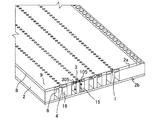
図14は、本実施形態における液体吐出ヘッド10の一部を拡大した斜視図であり、インクが供給、排出される経路を示している。記録素子基板2の第2の面2b側に第1の共通流路15と第2の共通流路16が形成されている。第1の共通流路15と第2の共通流路16には常にインクが流れている。第1の共通流路15を流れるインクの一部が第1の連通孔105を介して圧力室4へ供給される。圧力室4へ供給されたインクは第2の連通孔305を介して、第2の共通流路16に排出される。第1の共通流路15から第2の共通流路16へのインクの流れは第1の共通流路15と第2の共通流路16の差圧によって得られる。このため、液体吐出ヘッド10でインクの吐出が行われている際に、吐出が行われていない圧力室4においてもインクの流れが生じ、増粘したインクやインク中の異物が第2の共通流路16に排出される。従って、圧力室4及び吐出口3におけるインクの滞留や増粘を抑制することができる。吐出周波数や周囲の吐出口3からのインク吐出量に応じ、第1の共通流路15から第2の共通流路16にインクが流れる状態と、第1の共通流路15と第2の共通流路16の双方から圧力室4にインクが供給される状態と、を選択することができる。
本実施形態では、インクが循環する流路構成により、インク特性の変化が少ない状態を保つことができ、最初の液滴の吐出から安定した吐出性能を得ることができる。また、増粘したインクが圧力室4に滞留しにくいため、第二の実施形態と同様にインク液滴の着弾位置のばらつきを抑えることができる。
FIG. 14 is an enlarged perspective view of a part of the liquid ejection head 10 in the present embodiment, and shows a route through which ink is supplied and ejected. A first common flow path 15 and a second common flow path 16 are formed on the second surface 2b side of the recording element substrate 2. Ink is always flowing in the first common flow path 15 and the second common flow path 16. A part of the ink flowing through the first common flow path 15 is supplied to the pressure chamber 4 through the first communication hole 105. The ink supplied to the pressure chamber 4 is discharged to the second common flow path 16 through the second communication hole 305. The flow of ink from the first common flow path 15 to the second common flow path 16 is obtained by the differential pressure between the first common flow path 15 and the second common flow path 16. Therefore, when the ink is ejected by the liquid ejection head 10, the ink flows even in the pressure chamber 4 where the ink is not ejected, and the thickened ink and the foreign matter in the ink are the second common. It is discharged to the flow path 16. Therefore, it is possible to suppress ink retention and thickening in the pressure chamber 4 and the ejection port 3. A state in which ink flows from the first common flow path 15 to the second common flow path 16 and a state in which the first common flow path 15 and the second common flow path 15 are common according to the discharge frequency and the amount of ink discharged from the surrounding discharge port 3. It is possible to select a state in which ink is supplied to the pressure chamber 4 from both of the flow paths 16.
In the present embodiment, due to the flow path configuration in which the ink circulates, it is possible to maintain a state in which there is little change in ink characteristics, and it is possible to obtain stable ejection performance from the ejection of the first droplet. Further, since the thickened ink does not easily stay in the pressure chamber 4, it is possible to suppress the variation in the landing position of the ink droplets as in the second embodiment.

本実施形態の変形例では、バイモルポンプやチューブポンプを用いてインクを循環させることができる。これらのポンプを用いる場合、ポンプ出力に起因するインクの脈動が発生する場合がある。本実施形態では、圧力室4がダンパと同様の機能を有しており、圧力室4に供給されるインクが壁面抵抗による整流効果を受ける。このため、インクの脈動によるインク流速の時間的な変動を低減することができる。その結果、ポンプ出力によるインクの脈動流に起因するインク流速のゆらぎを小さくすることが可能であり、インク液滴の着弾位置の時間的なばらつきを抑えることができる。
さらに、液体吐出装置の稼働開始時などインク循環の開始時に、吐出口3からの揮発で粘度が高くなったインクを循環させ、圧力室のほぼ全域を流速分布が均一化されたインク流で置換することができる。このため、インク液滴が安定的に吐出されるまでの所要時間を短くすることが可能となる。
In the modified example of this embodiment, the ink can be circulated by using a bimol pump or a tube pump. When these pumps are used, ink pulsation due to the pump output may occur. In the present embodiment, the pressure chamber 4 has the same function as the damper, and the ink supplied to the pressure chamber 4 receives a rectifying effect due to the wall resistance. Therefore, it is possible to reduce the temporal fluctuation of the ink flow velocity due to the pulsation of the ink. As a result, it is possible to reduce the fluctuation of the ink flow velocity caused by the pulsating flow of the ink due to the pump output, and it is possible to suppress the temporal variation of the landing position of the ink droplet.
Further, at the start of ink circulation such as when the liquid ejection device starts operation, the ink whose viscosity has increased due to volatilization from the ejection port 3 is circulated, and almost the entire area of the pressure chamber is replaced with an ink flow having a uniform flow velocity distribution. can do. Therefore, it is possible to shorten the time required for the ink droplets to be stably ejected.

(第四の実施形態)
本実施形態の液体吐出ヘッド10の基本的な構成は第三の実施形態と同様であり、特徴的な構成についてのみ、図13を用いて説明する。
エネルギー発生素子1は1200dpiの配列密度で配置されている。
本実施形態の液体吐出ヘッド10の主要部の寸法は以下のとおりである。
エネルギー発生素子1の長さDr:18μm
エネルギー発生素子1の幅Wr:10m
吐出口3の直径R:15μm
圧力室4の幅Wp:17.7μm
連通孔105,305の断面長さDh:20μm
連通孔105,305の幅Wh:30μm
液体流路6及び圧力室4の高さ(側壁8の高さ)Hp:3.5μm
第1の隔壁7の長さDs:70μm
第1の隔壁7の幅Ws:3.5μm
第2の隔壁307a,307b,407a,407bの長さDs:30μm
第2の隔壁307a,307b,407a,407bの幅Ws:3.5μm
両側の側壁8の間隔Di:150μm
吐出口形成部材9の厚み:4μm
インク粘度は2cPで、インク吐出量は1pLとしている。
(Fourth Embodiment)
The basic configuration of the liquid discharge head 10 of the present embodiment is the same as that of the third embodiment, and only the characteristic configuration will be described with reference to FIG.
The energy generating element 1 is arranged with an array density of 1200 dpi.
The dimensions of the main part of the liquid discharge head 10 of the present embodiment are as follows.
Length of energy generating element 1 Dr: 18 μm
Width of energy generating element 1 Wr: 10m
Diameter R of discharge port 3: 15 μm
Width Wp of pressure chamber 4: 17.7 μm
Cross-sectional length of communication holes 105 and 305 Dh: 20 μm
Width of communication holes 105 and 305 Wh: 30 μm
Height of liquid flow path 6 and pressure chamber 4 (height of side wall 8) Hp: 3.5 μm
Length of first partition wall 7 Ds: 70 μm
Width Ws of the first partition wall 7: 3.5 μm
Lengths of the second partition walls 307a, 307b, 407a, 407b Ds: 30 μm
Width Ws of the second partition wall 307a, 307b, 407a, 407b: 3.5 μm
Spacing between side walls 8 on both sides Di: 150 μm
Thickness of discharge port forming member 9: 4 μm
The ink viscosity is 2 cP, and the ink ejection amount is 1 pL.

本実施形態では、等価流速域の下限値はWr/Wp=0.56である。図5を参照すると、圧力室4のアスペクト比が5.0以上のとき等価流速域が0.57以上となり、エネルギー発生素子1上で略均一とみなせるインク流速分布が得られる。その結果、インク液滴の着弾位置のばらつきを抑えることができる。 In the present embodiment, the lower limit of the equivalent flow velocity region is Wr / Wp = 0.56. Referring to FIG. 5, when the aspect ratio of the pressure chamber 4 is 5.0 or more, the equivalent flow velocity region becomes 0.57 or more, and an ink flow velocity distribution that can be regarded as substantially uniform on the energy generating element 1 can be obtained. As a result, it is possible to suppress variations in the landing positions of the ink droplets.

1 エネルギー発生素子
2 記録素子基板
3 吐出口
4 圧力室
7 第1の隔壁
9 吐出口形成部材
1 Energy generating element 2 Recording element substrate 3 Discharge port 4 Pressure chamber 7 First partition wall 9 Discharge port forming member

Claims (18)

液体に吐出のためのエネルギーを与える複数のエネルギー発生素子を備えた記録素子基板と、前記エネルギー発生素子と対向し前記液体を吐出する複数の吐出口を備えた吐出口形成部材と、前記記録素子基板と前記吐出口形成部材との間を延びる複数の第1の隔壁と、を有し、
前記複数の第1の隔壁は、それぞれが一つの前記エネルギー発生素子を備えた複数の圧力室を形成し、
前記複数のエネルギー発生素子は、前記記録素子基板の第1の面に第1の方向に配列されており、前記吐出口の中心を通り前記第1の面と直交し前記第1の方向と平行な前記圧力室の断面において、前記液体の流速が最大値の95%以上となる範囲の前記第1の方向における長さが、前記エネルギー発生素子の前記第1の方向における寸法より大きい、液体吐出ヘッド。
A recording element substrate provided with a plurality of energy generating elements that give energy for discharging the liquid, a discharge port forming member having a plurality of discharging ports facing the energy generating element and discharging the liquid, and the recording element. It has a plurality of first partition walls extending between the substrate and the discharge port forming member.
The plurality of first partition walls form a plurality of pressure chambers, each of which comprises one said energy generating element.
The plurality of energy generating elements are arranged on the first surface of the recording element substrate in the first direction, pass through the center of the discharge port, are orthogonal to the first surface, and are parallel to the first direction. In the cross section of the pressure chamber, the length in the first direction in the range where the flow velocity of the liquid is 95% or more of the maximum value is larger than the dimension of the energy generating element in the first direction. head.
前記複数の第1の隔壁は前記第1の面と平行で前記第1の方向と直交する第2の方向に延び、前記第1の隔壁の長さは前記エネルギー発生素子の前記第2の方向における寸法より大きい、請求項1に記載の液体吐出ヘッド。 The plurality of first partition walls extend in a second direction parallel to the first surface and orthogonal to the first direction, and the length of the first partition wall is the length of the energy generating element in the second direction. The liquid discharge head according to claim 1, which is larger than the size in the above. 前記記録素子基板を貫通し、前記圧力室と連通し、前記圧力室に前記液体を供給する複数の第1の連通孔を有し、前記圧力室の流路断面積が前記第1の連通孔の最少の流路断面積より小さい、請求項1または2に記載の液体吐出ヘッド。 It has a plurality of first communication holes that penetrate the recording element substrate, communicate with the pressure chamber, and supply the liquid to the pressure chamber, and the flow path cross-sectional area of the pressure chamber is the first communication hole. The liquid discharge head according to claim 1 or 2, which is smaller than the minimum flow path cross-sectional area of the above. 前記複数の第1の連通孔は前記第1の方向に配列されており、前記複数の第1の連通孔の配列間隔は前記複数のエネルギー発生素子の配列間隔より大きい、請求項に記載の液体吐出ヘッド。 Wherein the plurality of first communicating holes are arranged in the first direction, the arrangement interval of the plurality of first communicating hole is larger than the arrangement interval of the plurality of energy generating elements, according to claim 3 Liquid discharge head. 前記第1の連通孔を前記圧力室に接続し、前記液体を前記圧力室に供給する液体流路と、前記第1の隔壁から前記液体流路に突き出す突起と、を有している、請求項またはに記載の液体吐出ヘッド。 Claimed to have a liquid flow path connecting the first communication hole to the pressure chamber and supplying the liquid to the pressure chamber, and a protrusion protruding from the first partition wall into the liquid flow path. liquid discharge head according to claim 3 or 4. 前記第1の連通孔を前記圧力室に接続し、前記液体を前記圧力室に供給する液体流路を有し、前記第1の面と垂直な方向における前記液体流路の最小高さが前記吐出口の最大径より小さい、請求項またはに記載の液体吐出ヘッド。 The first communication hole is connected to the pressure chamber, the liquid flow path for supplying the liquid to the pressure chamber is provided, and the minimum height of the liquid flow path in a direction perpendicular to the first surface is the said. The liquid discharge head according to claim 3 or 4, which is smaller than the maximum diameter of the discharge port. 前記第1の連通孔を前記圧力室に接続し、前記液体を前記圧力室に供給する液体流路を有し、前記第1の面と垂直な方向における前記液体流路の高さが前記液体流路に沿った位置によって異なる、請求項またはに記載の液体吐出ヘッド。 The first communication hole is connected to the pressure chamber, the liquid flow path for supplying the liquid to the pressure chamber is provided, and the height of the liquid flow path in a direction perpendicular to the first surface is the liquid. The liquid discharge head according to claim 3 or 4, which varies depending on the position along the flow path. 前記複数の第1の連通孔からなる連通孔列の前記第1の方向における中心位置が、前記複数の吐出口からなる吐出口列の前記第1の方向における中心位置と、前記第1の方向において一致している、請求項からのいずれか1項に記載の液体吐出ヘッド。 The center position of the communication hole row composed of the plurality of first communication holes in the first direction is the center position of the discharge port row consisting of the plurality of discharge ports in the first direction and the first direction. The liquid discharge head according to any one of claims 3 to 7 , which is consistent with the above. 前記圧力室に関し前記第1の連通孔の反対側に、前記記録素子基板を貫通し、前記圧力室と連通する第2の連通孔を有している、請求項からのいずれか1項に記載の液体吐出ヘッド。 Any one of claims 3 to 8 , which has a second communication hole that penetrates the recording element substrate and communicates with the pressure chamber on the opposite side of the first communication hole with respect to the pressure chamber. The liquid discharge head described in. 液体に吐出のためのエネルギーを与える複数のエネルギー発生素子を備えた記録素子基板と、前記エネルギー発生素子と対向し前記液体を吐出する複数の吐出口を備えた吐出口形成部材と、前記記録素子基板と前記吐出口形成部材との間を延びる複数の第1の隔壁と、を有し、
前記複数の第1の隔壁は、それぞれが一つの前記エネルギー発生素子を備えた複数の圧力室を形成し、
前記複数のエネルギー発生素子は、前記記録素子基板の第1の面に第1の方向に配列されており、
前記記録素子基板を貫通し、前記圧力室と連通し、前記圧力室に前記液体を供給する複数の第1の連通孔を有し、前記圧力室の流路断面積が前記第1の連通孔の最少の流路断面積より小さく、
互いに隣接する前記第1の連通孔の間に第2の隔壁が設けられている、液体吐出ヘッド。
A recording element substrate provided with a plurality of energy generating elements that give energy for discharging the liquid, a discharge port forming member having a plurality of discharging ports facing the energy generating element and discharging the liquid, and the recording element. It has a plurality of first partition walls extending between the substrate and the discharge port forming member.
The plurality of first partition walls form a plurality of pressure chambers, each of which comprises one said energy generating element.
The plurality of energy generating elements are arranged on the first surface of the recording element substrate in the first direction.
It has a plurality of first communication holes that penetrate the recording element substrate, communicate with the pressure chamber, and supply the liquid to the pressure chamber, and the flow path cross-sectional area of the pressure chamber is the first communication hole. Smaller than the minimum flow path cross-sectional area of
Together the second partition wall between adjacent said first communication hole is provided, the liquid discharge head.
複数の前記第2の隔壁が互いに隣接する前記第1の連通孔の間に設けられている、請求項1に記載の液体吐出ヘッド。 A plurality of said second partition wall is provided between adjacent said first communication hole with each other, the liquid discharge head according to claim 1 0. 前記第2の隔壁は前記第1の隔壁から分離している、請求項1または1に記載の液体吐出ヘッド。 The second partition is separate from the first partition wall, the liquid discharge head according to claim 1 0 or 1 1. 前記第2の隔壁は前記第1の隔壁と一体化されている、請求項1または1に記載の液体吐出ヘッド。 The second partition is integral with the first partition wall, the liquid discharge head according to claim 1 0 or 1 1. 前記圧力室内の液体は当該圧力室の外部との間で循環される、請求項1から1のいずれか1項に記載の液体吐出ヘッド。 The pressure chamber of the liquid is circulated between the outside of the pressure chamber, the liquid discharge head according to any one of claims 1 1 3. 前記複数のエネルギー発生素子は、発熱して液体を発泡させることで前記液体を吐出する、請求項1から1のいずれか1項に記載の液体吐出ヘッド。 The plurality of energy generating elements, heating to ejecting the liquid by foaming the liquid, the liquid discharge head according to any one of claims 1 1 4. 複数の前記記録素子基板を備え、被記録媒体の幅に対応した長さを有する、請求項1から1のいずれか1項に記載の液体吐出ヘッド。 Comprising a plurality of said recording element substrate, having a length corresponding to the width of the recording medium, a liquid discharge head according to any one of claims 1 1 5. 長手方向を有し、前記複数の記録素子基板は前記長手方向に沿って直線状に配列される、請求項1に記載の液体吐出ヘッド。 The liquid discharge head according to claim 16 , which has a longitudinal direction and in which the plurality of recording element substrates are linearly arranged along the longitudinal direction. 請求項に記載の液体吐出ヘッドと、前記圧力室の液体を前記第1の連通孔から前記第2の連通孔に向けて循環させる手段と、を有する液体吐出装置。 A liquid discharge device comprising the liquid discharge head according to claim 9 and means for circulating the liquid in the pressure chamber from the first communication hole to the second communication hole.
JP2016137371A 2016-07-12 2016-07-12 Liquid discharge head and liquid discharge device Active JP6794159B2 (en)

Priority Applications (2)

Application Number Priority Date Filing Date Title
JP2016137371A JP6794159B2 (en) 2016-07-12 2016-07-12 Liquid discharge head and liquid discharge device
US15/644,590 US10220617B2 (en) 2016-07-12 2017-07-07 Liquid discharge head and liquid discharge apparatus

Applications Claiming Priority (1)

Application Number Priority Date Filing Date Title
JP2016137371A JP6794159B2 (en) 2016-07-12 2016-07-12 Liquid discharge head and liquid discharge device

Publications (3)

Publication Number Publication Date
JP2018008391A JP2018008391A (en) 2018-01-18
JP2018008391A5 JP2018008391A5 (en) 2019-07-18
JP6794159B2 true JP6794159B2 (en) 2020-12-02

Family

ID=60942453

Family Applications (1)

Application Number Title Priority Date Filing Date
JP2016137371A Active JP6794159B2 (en) 2016-07-12 2016-07-12 Liquid discharge head and liquid discharge device

Country Status (2)

Country Link
US (1) US10220617B2 (en)
JP (1) JP6794159B2 (en)

Families Citing this family (1)

* Cited by examiner, † Cited by third party
Publication number Priority date Publication date Assignee Title
US10457062B2 (en) * 2016-01-08 2019-10-29 Canon Kabushiki Kaisha Liquid discharge head

Family Cites Families (2)

* Cited by examiner, † Cited by third party
Publication number Priority date Publication date Assignee Title
US8308275B2 (en) 2010-10-26 2012-11-13 Eastman Kodak Company Dispenser including array of liquid dispensing elements
JP6271898B2 (en) * 2013-07-29 2018-01-31 キヤノン株式会社 Liquid ejection head and recording apparatus

Also Published As

Publication number Publication date
JP2018008391A (en) 2018-01-18
US10220617B2 (en) 2019-03-05
US20180015723A1 (en) 2018-01-18

Similar Documents

Publication Publication Date Title
KR102383356B1 (en) Liquid ejection head and liquid ejection apparatus
JP3927854B2 (en) Inkjet recording head
JP4323947B2 (en) Inkjet recording head
JP5362090B2 (en) Liquid discharge head
US8087758B2 (en) Liquid droplet ejecting head and liquid droplet ejecting apparatus
KR101122435B1 (en) Liquid ejection head, inkjet printing apparatus and liquid ejecting method
JP4027282B2 (en) Inkjet recording head
US7735962B2 (en) Ink jet print head
JP2010000649A (en) Recording head
JP5753739B2 (en) Droplet discharge head
JP5288825B2 (en) Inkjet recording head
KR100553623B1 (en) Ink jet record head
KR20130016073A (en) Liquid ejection head
JP5393082B2 (en) Liquid discharge head
JP6794159B2 (en) Liquid discharge head and liquid discharge device
JP2009132080A (en) Inkjet recording head
US11312135B2 (en) Liquid ejecting head
JP4137164B2 (en) Inkjet recording head
US10744778B2 (en) Liquid ejection head
JP2024007321A (en) Liquid ejection head and liquid ejection device
US20240009995A1 (en) Liquid ejection head and liquid ejection apparatus
JP6120645B2 (en) Liquid discharge head
JP2002273870A (en) Ink jet printing head
JP2005125696A (en) Inkjet recording head
JP2011025556A (en) Ink jet recording head

Legal Events

Date Code Title Description
A521 Request for written amendment filed

Free format text: JAPANESE INTERMEDIATE CODE: A523

Effective date: 20190603

A621 Written request for application examination

Free format text: JAPANESE INTERMEDIATE CODE: A621

Effective date: 20190603

A977 Report on retrieval

Free format text: JAPANESE INTERMEDIATE CODE: A971007

Effective date: 20200313

A131 Notification of reasons for refusal

Free format text: JAPANESE INTERMEDIATE CODE: A131

Effective date: 20200324

A521 Request for written amendment filed

Free format text: JAPANESE INTERMEDIATE CODE: A523

Effective date: 20200522

TRDD Decision of grant or rejection written
A01 Written decision to grant a patent or to grant a registration (utility model)

Free format text: JAPANESE INTERMEDIATE CODE: A01

Effective date: 20201013

A61 First payment of annual fees (during grant procedure)

Free format text: JAPANESE INTERMEDIATE CODE: A61

Effective date: 20201111

R151 Written notification of patent or utility model registration

Ref document number: 6794159

Country of ref document: JP

Free format text: JAPANESE INTERMEDIATE CODE: R151