JP6792334B2 - Mass spectrometer with improved magnetic sectors - Google Patents
Mass spectrometer with improved magnetic sectors Download PDFInfo
- Publication number
- JP6792334B2 JP6792334B2 JP2015552038A JP2015552038A JP6792334B2 JP 6792334 B2 JP6792334 B2 JP 6792334B2 JP 2015552038 A JP2015552038 A JP 2015552038A JP 2015552038 A JP2015552038 A JP 2015552038A JP 6792334 B2 JP6792334 B2 JP 6792334B2
- Authority
- JP
- Japan
- Prior art keywords
- mass spectrometer
- magnetic
- mass
- sector
- angle
- Prior art date
- Legal status (The legal status is an assumption and is not a legal conclusion. Google has not performed a legal analysis and makes no representation as to the accuracy of the status listed.)
- Active
Links
Images


Classifications
-
- H—ELECTRICITY
- H01—ELECTRIC ELEMENTS
- H01J—ELECTRIC DISCHARGE TUBES OR DISCHARGE LAMPS
- H01J49/00—Particle spectrometers or separator tubes
- H01J49/26—Mass spectrometers or separator tubes
- H01J49/28—Static spectrometers
-
- H—ELECTRICITY
- H01—ELECTRIC ELEMENTS
- H01J—ELECTRIC DISCHARGE TUBES OR DISCHARGE LAMPS
- H01J49/00—Particle spectrometers or separator tubes
- H01J49/26—Mass spectrometers or separator tubes
- H01J49/28—Static spectrometers
- H01J49/30—Static spectrometers using magnetic analysers, e.g. Dempster spectrometer
-
- H—ELECTRICITY
- H01—ELECTRIC ELEMENTS
- H01J—ELECTRIC DISCHARGE TUBES OR DISCHARGE LAMPS
- H01J49/00—Particle spectrometers or separator tubes
- H01J49/02—Details
- H01J49/025—Detectors specially adapted to particle spectrometers
-
- H—ELECTRICITY
- H01—ELECTRIC ELEMENTS
- H01J—ELECTRIC DISCHARGE TUBES OR DISCHARGE LAMPS
- H01J49/00—Particle spectrometers or separator tubes
- H01J49/02—Details
- H01J49/20—Magnetic deflection
Description
本発明は、質量分析器に関する。本発明は、特に、イオンを、それらの質量対電荷比に応じて分離するために用いられる非スキャニング型磁気セクタ機器を用いる質量分析器に関する。 The present invention relates to a mass spectrometer. The present invention relates specifically to mass spectrometers using non-scanning magnetic sector instruments used to separate ions according to their mass-to-charge ratio.
質量分析は、分子またはサンプルを構成する要素を決定するために一般的に用いられる分析技術である。質量分析器は、一般的にはイオン源、質量分離器、及び検出器を備える。イオン源は、例えば、サンプル分子の気体相、液体相、または固体相をイオン、即ち電気的に非中性の荷電した原子または分子に変換することが可能な装置であり得る。いくつかのイオン化技術が従来技術において公知であり、イオン源装置の特定の構造は、本明細書中では詳述しない。或いは、質量分析器によって解析されるイオンは、気体相、液体相、または固体相にあるサンプルと、レーザ、イオンまたは電子ビームなどの照射源との間の相互作用から生じ得る。その場合、イオンを放出するサンプルがイオン源と考えられる。 Mass spectrometry is an analytical technique commonly used to determine the components that make up a molecule or sample. Mass spectrometers generally include an ion source, a mass separator, and a detector. The ion source can be, for example, an apparatus capable of converting the gas, liquid, or solid phase of a sample molecule into an ion, an electrically non-neutral charged atom or molecule. Some ionization techniques are known in the prior art, and the particular structure of the ion source device is not detailed herein. Alternatively, the ions analyzed by the mass spectrometer may result from the interaction of the sample in the gas, liquid, or solid phase with an irradiation source such as a laser, ion, or electron beam. In that case, the sample that releases the ions is considered to be the ion source.
イオン源を起源とするイオンビームは、イオンをそれらの質量対電荷比に応じて分離、または分類すること可能な質量分析器を用いて分析される。この比率は、典型的にはm/zと表され、mは統一原子質量単位で表された被分析物の質量であり、zはイオンがもつ素電荷の数である。非相対論的な場合においてはローレンツ力とニュートンの運動の第2法則が、空間における荷電粒子の運動を特徴付ける。従って、質量分析器は、イオン源によって生成されるイオンを分離するために、種々の公知の組み合わせ方で電界及び/または磁界を利用している。特定の質量対電荷比を有するイオンは、質量分析器において特定の軌跡を辿る。異なる質量対電荷比のイオンは、それぞれ異なる軌跡を辿るので、観察された軌跡に基づいて被分析物の組成を決定し得る。波動ビームに含まれる異なる波長のスペクトルの生成を可能にする光学分光計のアナロジーによって、質量分析器は、分子またはサンプルに含まれる異なる質量対電荷比のスペクトルの生成を可能にする。 Ion beams originating from an ion source are analyzed using a mass spectrometer capable of separating or classifying the ions according to their mass-to-charge ratio. This ratio is typically expressed as m / z, where m is the mass of the object to be analyzed expressed in unified atomic mass units, and z is the number of elementary charges of the ion. In the non-relativistic case, Lorentz force and Newton's second law of motion characterize the motion of charged particles in space. Therefore, mass spectrometers utilize electric and / or magnetic fields in various known combinations to separate the ions produced by the ion source. Ions with a particular mass-to-charge ratio follow a particular trajectory in a mass spectrometer. Ions with different mass-to-charge ratios follow different trajectories, so the composition of the object to be analyzed can be determined based on the observed trajectories. An optical spectrometer analogy that allows the generation of spectra of different wavelengths contained in a wave beam allows a mass spectrometer to generate spectra of different mass-to-charge ratios contained in a molecule or sample.
イオンを検出するために、質量分析器の出口において種々の既知の装置を用いることができる。そのような検出器は、位置検出型(position sensitive)でもそうでないものでもよく、公知のものである。それらの機能は、本明細書中では特に説明はしない。一般的に、検出器は、インジケータ(指示物)量の値を測定することができる。検出器は、被分析物に存在する各イオンの存在量を計算するためのデータを提供する。 Various known devices can be used at the outlet of the mass spectrometer to detect the ions. Such detectors may or may not be position sensitive and are known. These functions are not specifically described herein. In general, the detector can measure the value of the indicator amount. The detector provides data for calculating the abundance of each ion present in the object to be analyzed.
セクタ機器は、特定のタイプの質量分析機器である。セクタ機器は、磁界を用いるか、または電界と磁界の組み合わせを用いて、荷電粒子の経路及び/または速度に影響を与える。一般に、イオンの軌跡は、それらイオンがセクタ機器を通過することによって曲げられるが、軽くて遅いイオンが、重くて早いイオンより大きく曲げられる。磁気セクタ機器は、一般に2つのクラスに属する。スキャニング型セクタ機器では磁界が変えられ、一種類のイオンのみが特定の形に調整された磁界において検出可能である。磁界の強度の範囲をスキャニングすることによって、質量対電荷比の範囲も連続して検出できる。非スキャニング型の磁気セクタ機器では、静磁界が使用される。イオンの範囲は、並行して同時に検出され得る。 A sector instrument is a particular type of mass spectrometer. Sector equipment uses magnetic fields or a combination of electric and magnetic fields to influence the path and / or velocity of charged particles. Generally, the trajectory of ions is bent by passing those ions through sector equipment, but light and slow ions are bent more than heavy and fast ions. Magnetic sector equipment generally belongs to two classes. In scanning sector equipment, the magnetic field is changed, and only one type of ion can be detected in a magnetic field adjusted to a specific shape. By scanning the range of magnetic field strength, the range of mass-to-charge ratio can also be detected continuously. A static magnetic field is used in non-scanning magnetic sector equipment. The range of ions can be detected in parallel and simultaneously.
質量分析器の分解能は、得られる質量スペクトルにおいて僅かに異なる質量対電荷比の2つのピークを分離する装置の能力の測定基準となる。分解能はR=m/Δmと定義され、ここでmは観察される質量の質量数でありΔmは分離され得る2つの質量の間の差である。質量分離は、検出面に沿った質量分散に変換される。Δmは、質量mに対応するピークの半値幅FWHMを測定することによって決定される。分解能は、観察される質量範囲のある範囲にわたって同一でないこともあり得る。 The resolution of a mass spectrometer is a measure of the device's ability to separate two peaks with slightly different mass-to-charge ratios in the resulting mass spectrum. The resolution is defined as R = m / Δm, where m is the mass number of the observed mass and Δm is the difference between the two masses that can be separated. Mass separation is transformed into mass dispersion along the detection plane. Δm is determined by measuring the full width at half maximum FWHM of the peak corresponding to the mass m. The resolutions may not be the same over a range of observed mass ranges.
非特許文献1に記載のMattauch−Herzog(マッタウフ・ヘルツォーク)型質量分析器は、典型的な高性能ワイドレンジ並行質量分析セクタ型の機器である。質量分析器として、この装置は、磁気セクタとそれに続く非スキャニング型セクタを使用している。この機器は、磁気セクタの出口における1つの直線的な焦点面上へのイオンの二重収束を提供し、そこである範囲の質量を同時に検出できる。二重収束の原理は、エネルギーが異なり角度が異なるイオンが、同じ平面に収束されるというものである。同時並行検出により、スキャニング型の質量分析器と比較して、検出効率が改善され、かつ装置の定量性能が改善される。システムの時間依存的な変動は除去される。しかし、Mattauch−Herzog型ジオメトリを用いた装置は、通常、大きい質量範囲において高性能を達成するために大型の磁気セクタを用いている。 The Mattauch-Herzog mass spectrometer described in Non-Patent Document 1 is a typical high-performance wide-range parallel mass spectrometry sector-type instrument. As a mass spectrometer, the device uses a magnetic sector followed by a non-scanning sector. The instrument provides double convergence of ions onto one linear focal plane at the exit of the magnetic sector, where a range of masses can be detected simultaneously. The principle of double convergence is that ions with different energies and different angles are converged on the same plane. Simultaneous parallel detection improves detection efficiency and improves instrument quantification performance compared to scanning mass spectrometers. Time-dependent fluctuations in the system are eliminated. However, devices using Mattach-Herzog geometry typically use large magnetic sectors to achieve high performance over large mass ranges.
いくつかのジオメトリの変形形態が、例えば非特許文献2、非特許文献3、または非特許文献4に記載のように、空間的にコンパクトな質量分析器として提案されてきた。しかし、これらの設計では性能面が限定される。一回の取得について並行して検出可能な質量対電荷比の範囲は、10単位未満にしかわたっておらず、質量分解能は、数十から2、3百に限定されている。 Several geometry variants have been proposed as spatially compact mass spectrometers, for example as described in Non-Patent Document 2, Non-Patent Document 3, or Non-Patent Document 4. However, these designs have limited performance. The range of mass-to-charge ratios that can be detected in parallel for a single acquisition is less than 10 units, and the mass resolution is limited to tens to a few hundred.
特許文献1には、多重同時検出が可能な非スキャニング型磁気セクタを備える質量分析器であって、質量分析器が回動することにより低分解能モードと高分解能モードとの間で切り換えられる、質量分析器が開示されている。 Patent Document 1 describes a mass spectrometer including a non-scanning type magnetic sector capable of multiple simultaneous detection, and the mass is switched between a low resolution mode and a high resolution mode by rotating the mass spectrometer. The analyzer is disclosed.
特許文献2には、小型セクタ並行型質量分析器が開示されている。達成された質量分解能は330FWHMである。達成された質量分解能は、同じ装置に関連する非特許文献3で報告されている。 Patent Document 2 discloses a small sector parallel mass spectrometer. The mass resolution achieved is 330 FWHM. The achieved mass resolution has been reported in Non-Patent Document 3 relating to the same device.
従って、そのような公知の装置は、分解能が少なくとも1500で、質量範囲が1〜35原子質量単位(amu)の用途には適したものではない。 Therefore, such known devices are not suitable for applications with a resolution of at least 1500 and a mass range of 1-35 atomic mass units (amu).
そのような高性能が要求される典型的な用途は、例えば、表面の水における硝酸性物質塩汚染の検出の分野等がある。現在も、窒素の同位体の分野では、依然として厄介なサンプリングや、複雑で大規模な研究室用の質量分析器に依拠している。酸素や水素の同位体の解析のため及び硝酸塩の15N及び18Oの解析のための現場への持ち運び用の磁場型質量分析器は、質量干渉を除去するために少なくとも1500の質量分解能を必要とし、またその分析器は軽量で堅固なものでなければならない。 Typical applications that require such high performance include, for example, the field of detecting nitrate contamination in surface water. Even today, the field of nitrogen isotopes still relies on cumbersome sampling and complex, large-scale laboratory mass spectrometers. On-site magnetic mass spectrometers for the analysis of oxygen and hydrogen isotopes and for the analysis of 15 N and 18 O of nitrates require at least 1500 mass resolutions to eliminate mass interference. And the analyzer must be lightweight and robust.
本発明の目的は、非スキャニング型磁気セクタ機器を備え、従来技術の不都合の少なくともいくつかを解決する質量分析器を提供することにある。 An object of the present invention is to provide a mass spectrometer comprising a non-scanning magnetic sector device that solves at least some of the inconveniences of the prior art.
本発明の第1の態様によれば、イオン源と、前記イオン源を起源とするイオンを、それらの質量対電荷比に応じて分離するための非スキャニング型磁気セクタと、検出手段とを備える質量分析器が提供される。前記磁気セクタは、イオン入口面(平面)と、前記イオン入口面に対して異なる角度で配置された少なくとも2つのイオン出口面(平面)とを有する。前記イオン源は、イオン源装置、または入射放射線の下でイオンを放出するサンプルであり得る。 According to the first aspect of the present invention, an ion source, a non-scanning magnetic sector for separating ions originating from the ion source according to their mass-to-charge ratio, and a detection means are provided. A mass spectrometer is provided. The magnetic sector has an ion inlet surface (plane) and at least two ion exit surfaces (planes) arranged at different angles with respect to the ion inlet surface. The ion source can be an ion source device or a sample that emits ions under incident radiation.
好ましくは、前記磁気セクタは、前記イオン入口面に対して異なる角度で配置された2つのイオン出口面を有する。 Preferably, the magnetic sector has two ion exit surfaces arranged at different angles with respect to the ion inlet surface.
第1の出口面は、第1のイオン質量範囲に対応し、好ましくは、入口面に対して第1の角度で配置され得る。前記第2出口面は、第2のイオン質量範囲に対応し、好ましくは、入口面に対して第2の角度で配置され得る。前記第1の角度は、前記第2の角度より小さい開口を形成するようにするのが有利であり得る。従って、前記第1の角度は、前記第2の角度より小さい。 The first outlet surface corresponds to the first ion mass range and may preferably be disposed at a first angle with respect to the inlet surface. The second outlet surface corresponds to a second ion mass range and may preferably be disposed at a second angle with respect to the inlet surface. It may be advantageous for the first angle to form an opening smaller than the second angle. Therefore, the first angle is smaller than the second angle.
角度の大きさは、前記第2の角度と前記第1の角度との差が、10度〜30度または17〜20度の範囲であり得るようにするのが更に好ましい場合もある。有利な形態では、前記第1の角度が60度の開きを有し、前記第2の角度が81.5度の開きを有し得る。 The magnitude of the angle may be more preferably such that the difference between the second angle and the first angle can be in the range of 10 to 30 degrees or 17 to 20 degrees . In an advantageous embodiment, the first angle may have an opening of 60 degrees and the second angle may have an opening of 81.5 degrees.
前記検出手段は、少なくとも1つの検出器を含み得る。前記検出器は、前記検出器の位置の変更を可能にするポジショニングステージ上に載置され得る。好ましくは、少なくとも2つの検出器が設けられ得る。各検出器の位置は、前記磁気セクタから前記出口面の1つを通して放出されたイオンが収束する収束面に概ね対応する。 The detection means may include at least one detector. The detector may be placed on a positioning stage that allows the position of the detector to be repositioned. Preferably, at least two detectors may be provided. The position of each detector roughly corresponds to a converging surface where the ions emitted from the magnetic sector through one of the outlet surfaces converge.
前記磁気セクタは、磁石の層とポールピースの層とを含んでなる積層構造体を含むのが好ましい。磁気セクタは、中央ギャップを更に含み得る。 The magnetic sector preferably includes a laminated structure including a layer of magnets and a layer of pole pieces. The magnetic sector may further include a central gap.
前記イオン源と前記磁気セクタは、好ましくは、イオン源によって生成されたイオンビームが、前記磁気セクタの前記入口面に垂直な方向に対してある角度で前記磁気セクタの入口面に当たるように配置され得る。前記角度は、好ましくは38度に実質的に等しい角度であり得る。 The ion source and the magnetic sector are preferably arranged so that the ion beam generated by the ion source hits the inlet surface of the magnetic sector at an angle with respect to the direction perpendicular to the inlet surface of the magnetic sector. obtain. The angle can preferably be an angle substantially equal to 38 degrees.
好ましくは、前記装置は、前記イオン源の下流で、かつ前記磁気セクタの上流に配置された静電気セクタを含み得る。 Preferably, the device may include electrostatic sectors located downstream of the ion source and upstream of the magnetic sector.
更に、磁気分路が、好ましくは、前記静電気セクタの下流で、かつ前記磁気セクタの上流に配置され得る。この磁気分路は、前記磁気セクタの前記入口面と平行に配置され得る。或いは、前記磁気分路は、前記磁気セクタの前記入口面に対してある角度をなすように配置され得る。更に、前記磁気分路は、前記静電気セクタの前記出口面と平行に配置され得る。 Further, the magnetic shunt may preferably be located downstream of the electrostatic sector and upstream of the magnetic sector. This magnetic shunt may be arranged parallel to the inlet surface of the magnetic sector. Alternatively, the magnetic shunt may be arranged at an angle to the inlet surface of the magnetic sector. Further, the magnetic shunt may be arranged parallel to the outlet surface of the electrostatic sector.
好ましくは、前記装置は、可搬性を有するものであり得る。前記静電気セクタ、前記磁気分路、前記磁気セクタ、及び前記検出手段は、好ましくは20cm×15cm×10cmの寸法の箱内にぴったりと収まるようなサイズとされ得る。 Preferably, the device can be portable. The electrostatic sector, the magnetic shunt, the magnetic sector, and the detection means may be sized to fit snugly within a box measuring preferably 20 cm x 15 cm x 10 cm.
本発明の別の態様によれば、イオン源と、静電気セクタと、前記静電気セクタの下流に配置された、前記イオン源を起源とするイオンを、それらの質量対電荷比に応じて分離するための非スキャニング型磁気セクタと、検出手段と、磁気分路とを備えた質量分析器が提供される。前記磁気分路は、前記静電気セクタの下流で、かつ前記磁気セクタの上流に配置される。前記磁気分路は、前記磁気セクタのイオン入口面に対してある角度で配置される。前記磁気分路の位置は、前記磁気セクタのフリンジ磁界の形状に影響を与える。具体的には、前記静電気セクタと前記磁気セクタとの間のドリフト空間、より詳細には、前記磁気セクタのイオン入力面に沿ったフリンジ磁界が、前記磁気分路の位置のために均一でなくなる。 According to another aspect of the present invention, in order to separate the ion source, the electrostatic sector, and the ions originating from the ion source located downstream of the electrostatic sector according to their mass-to-charge ratios. A mass spectrometer equipped with a non-scanning magnetic sector, detection means, and a magnetic shunt is provided. The magnetic shunt is located downstream of the electrostatic sector and upstream of the magnetic sector. The magnetic shunt is arranged at an angle with respect to the ion inlet surface of the magnetic sector. The position of the magnetic shunt affects the shape of the fringe magnetic field of the magnetic sector. Specifically, the drift space between the electrostatic sector and the magnetic sector, or more specifically, the fringe magnetic field along the ion input surface of the magnetic sector, becomes non-uniform due to the location of the magnetic shunt. ..
好ましくは、前記磁気分路は、前記静電気セクタの前記出口面と平行に配置され得る。 Preferably, the magnetic shunt can be arranged parallel to the outlet surface of the electrostatic sector.
前記静電気セクタは、好ましくは、その出口面が前記磁気セクタの前記入口面に垂直な方向に対して90度未満の角度を形成するように配置され得る。前記角度は、好ましくは38度に実質的に等しい角度である。 The electrostatic sector may preferably be arranged such that its outlet surface forms an angle of less than 90 degrees with respect to the direction perpendicular to the inlet surface of the magnetic sector. The angle is preferably an angle substantially equal to 38 degrees.
更に、前記磁気分路は、好ましくは鉄製である。前記磁気分路は、イオンビームの通路のために適合された開口を含み得る。 Further, the magnetic shunt is preferably made of iron. The magnetic shunt may include an aperture adapted for the passage of the ion beam.
前記質量分析器は、好ましくは、内部にその構成要素が配置される真空の筐体を含み得る。前記質量分析器は、被分析物を導入するためのサンプル入口を更に含み得る。 The mass spectrometer may preferably include a vacuum enclosure in which its components are located. The mass spectrometer may further include a sample inlet for introducing the object to be analyzed.
本発明による質量分析器は、いくつかの収束面に対して2000を優に超える分解能を達成する。その分解能は、磁気セクタの出口面のジオメトリを適宜定めることによって、特定の質量対電荷比範囲に対して微調整され得る。 The mass spectrometer according to the invention achieves resolutions well in excess of 2000 for some convergent surfaces. Its resolution can be fine-tuned for a particular mass-to-charge ratio range by appropriately defining the geometry of the exit surface of the magnetic sector.
水理学的な用途(特に同位体分析)における特定の使用法が見いだされる好ましい実施形態では、1〜2amu及び15〜35amuの両サブレンジに対応する2つの出口面が最適化される。各質量の範囲(サブレンジ)は、磁気セクタを通るとき異なる偏向角度で曲げられ、異なる収束面に収束する。シミュレーション結果では、シミュレートされたイオン源からの、約1度の角度広がりと約8.5eVのエネルギーの広がりを有するイオンビームの全ての質量が、2つの検出面に沿って十分に収束される。垂直方向では、ビーム幅は2mm未満である。作製された質量分析器は、イオン源を除き、長さ17cm、幅11cm、高さ7cmの中に収まる。従って、本発明による質量分析器は、高い性能を必要とし、機器の持ち運びがされるべき用途に特に適したものとなる。そのような用途として、限定しないが、表面の水における硝酸性物質汚染の検出や、地下水の水理学的同位体分析等が挙げられる。 In a preferred embodiment in which specific uses are found in hydraulic applications (particularly isotope analysis), two outlet planes corresponding to both 1-2 amu and 15-35 amu subranges are optimized. Each mass range (subrange) is bent at different deflection angles as it passes through the magnetic sector and converges on different convergence planes. The simulation results show that the entire mass of the ion beam from the simulated ion source, with an angular spread of about 1 degree and an energy spread of about 8.5 eV, is fully converged along the two detection planes. .. In the vertical direction, the beam width is less than 2 mm. The mass spectrometer produced fits within a length of 17 cm, a width of 11 cm, and a height of 7 cm, excluding the ion source. Therefore, the mass spectrometer according to the present invention requires high performance and is particularly suitable for applications in which the device should be carried. Such applications include, but are not limited to, detection of nitrate contamination in surface water, hydraulic isotope analysis of groundwater, and the like.
本発明のいくつかの実施形態について図面を参照して説明するが、本発明の範囲はこれらの実施形態に限定されない。 Although some embodiments of the present invention will be described with reference to the drawings, the scope of the present invention is not limited to these embodiments.
本欄では、好ましい実施形態及び図面に基づいて、本発明を更に詳細に説明する。本発明の異なる実施形態全てにわたって類似の概念を示すために類似の参照符合が用いられる。例えば、3つの異なる実施形態における本発明による質量分析器を示すために、符合100、200、300が用いられる。
In this section, the present invention will be described in more detail based on preferred embodiments and drawings. Similar reference numerals are used to indicate similar concepts across all the different embodiments of the invention. For example,
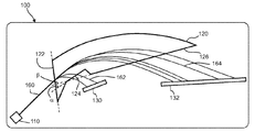
図1は、本発明による質量分析器100の概略図である。この質量分析器は、質量分析技術によって分析されるべきサンプルを導入するための入口(図示せず)を有する筐体として提供される。筐体は内部が真空状態とされ、イオン源110、磁気セクタ120、及び少なくとも2つの検出器130、132を有する。本明細書全体にわたって、検出器という用語は、スペクトルを計算し、そのスペクトルを表示するために異なる質量対電荷比のイオンを検出、定量することができる装置を表す。そのような装置または装置アセンブリは、従来技術として公知である。
FIG. 1 is a schematic view of a
イオン源またはイオン源群110はイオンビーム160を生成し、このイオンビームは、イオン源と磁気セクタ120の入口面122との間のドリフト空間を通過した後に磁気セクタの入口面122にある角度で当たる。磁気セクタは永久磁界を生成し、この磁界によりイオンは、それらの質量対電荷比に応じた特定の曲がった軌道に沿って移動する。磁気セクタ120は、一方の側において概ね曲がった形状を有し、その反対側にはイオン出口面が含まれる。別形態として、その概ね曲がった形状が、直線的なセグメントの組で湾曲を近似することによって与えられてもよい。図1の実施形態では、第1の出口面124及び第2の出口面126が、磁気セクタに設けられている。第1の出口面124は、入口面122の方向に対して角度αをなすように形成される。第2の出口面126は、入口面122の方向に対して角度βをなすように形成され、角度βは角度αより大きい角度である。両出口面の長さ及び角度は、特定のサブレンジのイオン162、164が、それぞれに対応する面124、126を通して磁気セクタから出るように選択される。図1に示すように、磁気セクタの形状は、出口面を含む側の入口面に隣接するところに更に平坦な領域を含み得る。イオンはこの平面を通して出ることはなく、その面のジオメトリが、磁気セクタのフリンジ磁界の形状に影響を与える。
The ion source or
本発明によれば、磁気セクタは、入口面に対して異なる角度で配置された複数の出口面を含み得る。明確化の目的で、以下の記述では、すべての実施形態で2つの異なる出口面が設けられた場合について説明するが、一般性が失われることはない。各出口面の長さ及び角度は、検出の必要のある質量対電荷比範囲のサブレンジに応じて適合され得る。 According to the present invention, the magnetic sector may include a plurality of exit planes arranged at different angles with respect to the inlet plane. For the purposes of clarification, the following description describes the case where two different exit surfaces are provided in all embodiments, but the generality is not lost. The length and angle of each outlet surface can be adapted according to the subrange of the mass-to-charge ratio range that needs to be detected.
イオン源110及び磁気セクタ120は、イオンビーム160がある角度で入口面122に当たるように配置される。入射角は好ましくは90度未満であり、更に好ましくは38度に概ね等しい角度である。両出口面の収束面は、磁気セクタからある距離だけ離れた位置にある。検出器130及び132は、検出器130が収束されたサブレンジ162を検出でき、検出器132が収束されたサブレンジ164を検出できるように適宜配置される。
The
図2は、磁気セクタ120の好ましい設計を斜視図として示したものである。この磁気セクタ機器は、磁石127とポールピース128を有するヨーク121を含む。磁石127とポールピース128の構成は、外側から内側に向かって磁石の次にポールピースが配置されるような構成である。中央の両ポールピース128の間に、ギャップ空間129が存在する。入口面122を通して磁気セクタに入り、出口面124または126を通して磁気セクタから出るイオンは、ギャップ空間129内を移動する。
FIG. 2 shows a preferred design of the
磁石127とポールピース128は磁気回路を形成し、ポールピースの間のギャップ129内に強力な磁界を形成する。好ましくは、磁石の質量を小さくするために、40MGOe(320kJ/m3)の最大エネルギー積を有するネオジム−鉄−ボロン磁石を用いる。好ましい実施形態では、磁石127の厚さは6mmである。ポールピース128は、ギャップ空間129における均一な磁界を維持するために、8mmの幅を有するのが好ましい。ヨーク121は、好ましくは14mmの厚さを有する。磁気セクタの縁の近傍のフリンジ磁界を最小とするために、ヨークとポールピースの両方において高い透磁率を有する純鉄を用いる。ギャップ空間129は、好ましくは4mmの高さを有する。ポールピース間のギャップにおいて好ましい設計を用いた場合に達成され得る最大磁界は、0.66Tである。
The
代替的な実施形態では、磁石が、対応する電磁石に置き換えられ得る。一般的に、質量分析器の検出可能な質量対電荷比の範囲は、磁気セクタのサイズと磁界の強さに応じて決まる。 In an alternative embodiment, the magnet can be replaced with the corresponding electromagnet. In general, the range of the mass-to-charge ratio that can be detected by a mass spectrometer depends on the size of the magnetic sector and the strength of the magnetic field.
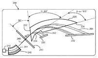
図3は、本発明による質量分析器200の好ましい実施形態の概略図である。この質量分析器は、質量分析技術によって分析されるべきサンプルを導入するための入口(図示せず)を有する筐体として提供される。筐体は内部が真空状態とされ、イオン源210、磁気セクタ220、及び少なくとも2つの検出器230、232を有する。
FIG. 3 is a schematic view of a preferred embodiment of the
質量分析器200は、静電気セクタ240を更に含む。静電気セクタ240は、イオン源210の下流でかつ磁気セクタ220の上流に配置される。磁気分路250は、静電気セクタ240と磁気セクタ220の間のドリフト空間に配置される。
The
イオン源210はイオンビーム260を生成し、このイオンビームは静電気セクタ240を通過する。静電気セクタの出口面241は、好ましくは磁気セクタの入口面222に対して90度未満の角度をなすように配向される。有利な形態として、静電気セクタの出口面241は、磁気セクタの入口面222に対して38度の角度をなすように配向される。この構成により、磁気セクタの入口面に対して垂直な方向と光学軸との間に正の傾斜角が形成される。これによって、面内方向にイオンビームを収束させないようにするための、磁気セクタのフリンジ磁界が適切に形成される。従って、収束面が、磁気セクタの出口面224、224から離れる方向に移動して、検出器230、232の取り付けや調節を行うことが容易になる。
The
面内方向(水平方向)及び面外方向(垂直方向)の両方向のイオンビームの収束を達成するためには、球形の静電気セクタを用いるのが好ましい。面外方向における収束は、収束面の垂直方向にある小さいスポットにイオンビームを収束させる。これによって1Dアレイ検出器の使用が容易になる。それらのアクティブ領域は概ね垂直方向に限定されているからである。そのような収束は、磁気セクタにおいて高い透過性を達成する助けにもなる。好ましい球形静電セクタの平均半径及び角度は、それぞれ30mm及び45度である。静電気セクタ240の電極間のギャップは10mmである。静電気セクタは、外側の電極にはイオンビームを偏向させるようにバイアスがかけられ、内側の電極は接地される、遅延モードで用いられる。これにより性能が向上することになる。好ましくは、5000eVのエネルギーを有するイオンビームを偏向させるために偏向電極には2670Vのバイアスがかけられる。
In order to achieve convergence of the ion beam in both the in-plane direction (horizontal direction) and the out-of-plane direction (vertical direction), it is preferable to use a spherical electrostatic sector. Out-of-plane convergence causes the ion beam to converge to a small spot perpendicular to the convergence plane. This facilitates the use of the 1D array detector. This is because their active areas are generally limited to the vertical direction. Such convergence also helps to achieve high transparency in the magnetic sector. The average radius and angle of the preferred spherical electrostatic sector are 30 mm and 45 degrees, respectively. The gap between the electrodes of the
磁気分路250は、好ましくは純鉄製であり、静電気セクタ240の下流でかつ磁気セクタの上流に配置される。磁気分路の目的は、フリンジ磁界が、静電気セクタにおけるイオンの軌道に影響を及ぼすのを防ぐことにある。磁気分路の厚さは、好ましくは約3mmである。磁気分路の構成は、質量分析器の性能に影響を与える重要なパラメータである。図3の好ましい実施形態では、磁気分路250は、イオンビームを通過させる開口を有し、静電気セクタ240の出口面241と平行に配置されている。従って、磁気分路は、磁気セクタ220の入口面222に対して38度の角をなすように傾斜している。これによって、磁気セクタの入口面に沿って不均一なフリンジ磁界が形成される。この不均一なフリンジ磁界は、異なる入射角及びエネルギーのイオンに対して異なる影響を与え、このことで収束面230、232における質量分析器の収束特性が改善することが確認された。
The
イオンビーム260は、磁気セクタ220の入口面222に38度の角度で当たる。気セクタは永久磁界を生成し、この永久磁界により、イオンは、磁気セクタのギャップにおいて、それらの質量対電荷比に応じた特定の曲がった軌道に沿って移動する。磁気セクタ220は、一方の側において概ね曲がった形状を有し、その反対側にはイオン出口面が含まれる。図3の実施形態では、第1の出口面224及び第2の出口面226が、磁気セクタに設けられている。第1の出口面224は、入口面222の方向に対して角度αをなすように形成される。第2の出口面226は、入口面222の方向に対して角度βをなすように形成され、角度βは角度αより大きい角度である。両出口面の長さ及び角度は、特定のサブレンジのイオン262、264が、それぞれに対応する面224、226を通して磁気セクタから出るように選択される。
The
好ましくは、磁気分路と静電気セクタとの間の距離は2.5cmであり、磁気分路と磁気セクタとの間の距離は1.5cmである。作製された質量分析器は、イオン源を除き、概ね17cm×11cmのフットプリントを占めるだけのものとなる。全ての構成要素は、二重収束条件の下で異なる質量のイオンがある収束面に収束されるように配置される必要があり、収束面は出口セクタの各出口からある距離に位置している必要がある。全ての質量を二重収束条件の下である収束面に収束させるためには、イオンビームは、静電気セクタと磁気セクタとの間のドリフト空間において平行化されている、即ちビームが静電気セクタから平行に発せられる必要がある。このことは、イオン源において、仮想的なイオン源と静電気セクタとの間の距離を調節するための収束レンズ(図示せず)を用いることにより達成され得る。図3の特定の設計では、仮想的イオン源が、静電気セクタからその前側に10mmの位置に配置されている。 Preferably, the distance between the magnetic shunt and the electrostatic sector is 2.5 cm and the distance between the magnetic shunt and the magnetic sector is 1.5 cm. The mass spectrometer produced, excluding the ion source, occupies a footprint of approximately 17 cm × 11 cm. All components must be arranged so that ions of different masses converge to a convergent plane under double convergence conditions, which is located at a distance from each exit of the exit sector. There is a need. In order to converge all masses to the convergence plane under the double convergence condition, the ion beam is parallelized in the drift space between the electrostatic sector and the magnetic sector, i.e. the beam is parallel from the electrostatic sector. Need to be issued to. This can be achieved by using a condensing lens (not shown) in the ion source to adjust the distance between the virtual ion source and the electrostatic sector. In the particular design of FIG. 3, the virtual ion source is located 10 mm in front of the electrostatic sector.
図3の好ましい実施形態では、磁気セクタの第1の出口面224と入口面222とによって形成される角度αが63度である。磁気セクタの第2の出口面と入口面222とによって形成される角度βは81.5度である。2つの角度の差は(β−α)=18.5度となる。第1の出口面は、1〜2amuの質量のイオンを検出するために最適化され、第2の出口面は、16〜35amuのサブレンジのために最適化される。この構成は、水理学的な用途、特に同位体分析のために特に有用である。
In a preferred embodiment of FIG. 3, the angle α formed by the
図4は、図3の好ましい実施形態による質量分析器の分解能を示すグラフである。具体的には、質量2amuについての分解能が、第1の出口面224と第2の出口面226との間の傾斜角の関数として示されている。従って、グラフの値(β−α)=0度は、磁気セクタにおいて、入口面に対して81.5度の角度をなす連続した1つの出口面しか設けられていない場合に対応する。その場合、質量2amuでの分解能は、約1350である。第1の出口面は、磁気セクタの本体内に深く切り込まれていることから、質量2amuにおける分解能は傾斜角によって変化することが確認された。(β−α)=18.5度の場合に最大値となることが確認され、このとき分解能は2000超となった。ある特定の用途に対する重要な各サブレンジに対して、類似の最適化技術を用いることができる。磁気セクタ全体のサイズを大型化することなく、分解能の顕著な改善が達成されている。
FIG. 4 is a graph showing the resolution of the mass spectrometer according to the preferred embodiment of FIG. Specifically, the resolution for mass 2amu is shown as a function of the tilt angle between the
図5は、図3の好ましい実施形態による質量分析器の分解能を示すグラフである。具体的には、第1の出口面224に対応する1〜2amuのサブレンジと、第2の出口面226に対応する16〜35amuのサブレンジにおける分解能が示されている。本発明のコンパクトな質量分析器によって2000かから3500超の分解能が達成されることが理解されよう。
FIG. 5 is a graph showing the resolution of the mass spectrometer according to the preferred embodiment of FIG. Specifically, the resolutions in the 1 to 2 amu subrange corresponding to the
図6は、図3の実施形態に類似しているが、磁気分路250が磁気セクタ320の入口面と平行に配置された点が異なっている、本発明の更に別の実施形態による質量分析器を示す。本発明によれば、磁気分路の位置は、図3に示す位置と図6の示す位置との間の任意の中間の角度をなす位置に適合させることができる。従って、磁気分路は、1つの軸に回転可能に取り付けられ得る。実験データは、特定の磁気セクタの設計について、図3に示すように磁気分路が静電気セクタの出口面と平行に配置された位置を有する場合に、その質量分析器の設計の全体の分解能が改善していることを示している。
FIG. 6 is similar to the embodiment of FIG. 3, except that the
下記の表1は、磁気分路が磁気セクタの入口面と平行な場合(図6)と、磁気分路が磁気セクタの入口面に対して38度の角度で配置されている場合(図3)の、質量2及び6amuにおいて観察された解像度をまとめたものである。 Table 1 below shows the case where the magnetic shunt is parallel to the entrance surface of the magnetic sector (FIG. 6) and the case where the magnetic shunt is arranged at an angle of 38 degrees with respect to the entrance surface of the magnetic sector (FIG. 3). ), The resolutions observed at masses 2 and 6 amu are summarized.

先と同様に、質量分析器または磁気セクタ全体のサイズを大型化することなく、分解能の顕著な改善が達成されている。 As before, significant improvements in resolution have been achieved without increasing the size of the mass spectrometer or the entire magnetic sector.
本発明の特定の好ましい実施形態について説明してきたが、本発明の実施に際して本発明の範囲を逸脱することなく種々の改変が可能であることは当業者には明らかであり、以上の特定の好ましい実施形態の詳細な説明は、例示のために提示されたものであることを理解されたい。本発明の範囲は、特許請求の範囲の各請求項の記載によって特定される。 Although the specific preferred embodiments of the present invention have been described, it is clear to those skilled in the art that various modifications can be made without departing from the scope of the present invention in carrying out the present invention, and the above specific preferred embodiments are described above. It should be understood that the detailed description of the embodiments are provided for illustration purposes. The scope of the present invention is specified by the description of each claim of the claims.
Claims (17)
イオン源(110;210;310)と、
前記イオン源を起源とするイオンを、それらの質量対電荷比に応じて分離するための非スキャニング型磁気セクタ(120;220;320)と、
検出手段(130,132;230,232;330,332)とを備え、
前記磁気セクタは、イオン入口平面(122;222;322)を備え、
前記磁気セクタは、前記イオン入口平面(122;222;322)に対して第1の角度(α)で配置されて1〜2amuの質量のイオンを検出するのに最適化された第1のイオン出口平面(124;224;324)と、前記イオン入口平面(122;222;322)に対して第2の角度(β)で配置されて16〜35amuの質量のイオンを検出するのに最適化された第2のイオン出口平面(126;226;326)とを備え、前記第2の角度と前記第1の角度との差が、17〜20度の範囲にあることを特徴とする質量分析器。 A mass spectrometer (100; 200; 300)
Ion sources (110; 210; 310) and
Non-scanning magnetic sectors (120; 220; 320) for separating ions originating from the ion source according to their mass-to-charge ratio, and
It is equipped with detection means (130, 132; 230, 232; 330, 332).
Said magnetic sector, ion entrance flat surface with a (122; 322; 222),
It said magnetic sector, the ions inlet flat surface (122; 222; 322) a first relative angle (alpha) are arranged in a first optimized to detect the mass of ions 1~2amu ion exit flat surface (124; 324; 224), said ion inlet flat surface for detecting (122; 322; 222) the second angle (beta) is arranged in respect of the mass of 16~35amu ions optimized second ion exit flat surface and a (126; 226 326), characterized in that the difference between the second angle and the first angle is in the range of 17 to 20 degrees Mass spectrometer.
前記第1の角度(α)は、前記第2の角度(β)より小さいことを特徴とする質量分析器。 The mass spectrometer according to claim 1.
It said first angle (alpha), the mass analyzer, characterized in that less than said second angle (beta).
前記第1の角度が63度であり、前記第2の角度が81.5度であることを特徴とする質量分析器。 The mass spectrometer according to claim 1 or 2.
A mass spectrometer characterized in that the first angle is 63 degrees and the second angle is 81.5 degrees.
前記検出手段が少なくとも1つの検出器を含み、前記検出器の各々の位置は、前記磁気セクタから前記イオン出口平面の1つを通して出たイオンが収束される収束面に対応することを特徴とする質量分析器。 The mass spectrometer according to any one of claims 1 to 3.
Wherein comprises detection means at least one detector, each position of the detector, and wherein said leaving the magnetic sector through one of said ion exit flat surface ions corresponds to the convergence plane to be converged Mass spectrometer.
前記磁気セクタ(120;220;320)が、ヨーク(121)が磁石(127)の層とポールピース(128)の層とを含んでなる積層構造体を含むことを特徴とする質量分析器。 The mass spectrometer according to any one of claims 1 to 4.
A mass spectrometer characterized in that the magnetic sectors (120; 220; 320) include a laminated structure in which the yoke (121) comprises a layer of magnets (127) and a layer of pole pieces (128).
前記磁気セクタが、中央ギャップ(129)を含むことを特徴とする質量分析器。 The mass spectrometer according to any one of claims 1 to 5.
A mass spectrometer characterized in that the magnetic sector includes a central gap (129).
前記イオン源(110;210;310)及び前記磁気セクタ(120;220;320)は、前記イオン源を起源とするイオンビームが、前記磁気セクタの前記イオン入口平面(122;222;322)に垂直な方向に対してある角度で前記イオン入口平面に当たるように配置されていることを特徴とする質量分析器。 The mass spectrometer according to any one of claims 1 to 6.
The ion source (110; 210; 310) and the magnetic sector (120; 220; 320), the ion beam of the ion source and origin, said ion inlet flat surface of the magnetic sector (122; 222; 322) mass analyzer, characterized in that it is arranged to strike the said ion inlet flat surface at an angle to the direction perpendicular to the.
前記角度が、38度に等しい角度であることを特徴とする質量分析器。 The mass spectrometer according to claim 7.
A mass spectrometer characterized in that the angle is equal to 38 degrees.
前記イオン源(210;310)の下流で、かつ前記磁気セクタ(220;320)の上流に配置された静電気セクタ(240;340)を更に含むことを特徴とする質量分析器。 The mass spectrometer according to any one of claims 1 to 8.
A mass spectrometer characterized by further including electrostatic sectors (240; 340) located downstream of the ion source (210; 310) and upstream of the magnetic sector (220; 320).
前記静電気セクタ(240;340)の下流で、かつ前記磁気セクタ(220;320)の上流に配置された磁気分路(250;350)を更に含むことを特徴とする質量分析器。 The mass spectrometer according to claim 9.
A mass spectrometer characterized by further including a magnetic shunt (250; 350) located downstream of the electrostatic sector (240; 340) and upstream of the magnetic sector (220; 320).
前記磁気分路(350)が、前記磁気セクタ(320)の前記イオン入口平面(322)と平行に配置されていることを特徴とする質量分析器。 The mass spectrometer according to claim 10.
Mass analyzer the magnetic shunt is (350), characterized in that it is arranged parallel to said ion inlet flat surface of the magnetic sector (320) and (322).
前記磁気分路(250)が、前記磁気セクタ(220)の前記イオン入口平面(222)に対してある角度で配置されていることを特徴とする質量分析器。 The mass spectrometer according to claim 10.
Mass analyzer the magnetic shunt is (250), wherein the are arranged in the angle with respect to the ion entrance flat surface (222) of the magnetic sector (220).
前記磁気分路(250)が、前記静電気セクタの出口平面(241)に平行に配置されていることを特徴とする質量分析器。 The mass spectrometer according to claim 10.
Mass analyzer the magnetic shunt is (250), characterized in that it is arranged parallel to the exit plane surface (241) of said electrostatic sector.
真空の筐体を更に含むことを特徴とする質量分析器。 The mass spectrometer according to any one of claims 1 to 13.
A mass spectrometer characterized by further including a vacuum enclosure.
サンプル入口を更に含むことを特徴とする質量分析器。 The mass spectrometer according to any one of claims 1 to 14.
A mass spectrometer characterized by further including a sample inlet.
可搬性を有することを特徴とする質量分析器。 The mass spectrometer according to any one of claims 1 to 15.
A mass spectrometer characterized by having portability.
前記静電気セクタ、前記磁気セクタ、及び前記検出手段を含む組立体が、20cm×15cm×10cmの寸法の体積内に収まることを特徴とする質量分析器。 The mass spectrometer according to any one of claims 9 to 13.
A mass spectrometer characterized in that an assembly including the electrostatic sector, the magnetic sector, and the detection means fits within a volume having a size of 20 cm × 15 cm × 10 cm.
Applications Claiming Priority (3)
| Application Number | Priority Date | Filing Date | Title |
|---|---|---|---|
| LU92131 | 2013-01-11 | ||
| LU92131A LU92131B1 (en) | 2013-01-11 | 2013-01-11 | Mass spectrometer with improved magnetic sector |
| PCT/EP2014/050103 WO2014108375A1 (en) | 2013-01-11 | 2014-01-07 | Mass spectrometer with improved magnetic sector |
Publications (2)
| Publication Number | Publication Date |
|---|---|
| JP2016509341A JP2016509341A (en) | 2016-03-24 |
| JP6792334B2 true JP6792334B2 (en) | 2020-11-25 |
Family
ID=47561749
Family Applications (1)
| Application Number | Title | Priority Date | Filing Date |
|---|---|---|---|
| JP2015552038A Active JP6792334B2 (en) | 2013-01-11 | 2014-01-07 | Mass spectrometer with improved magnetic sectors |
Country Status (8)
| Country | Link |
|---|---|
| US (1) | US9564306B2 (en) |
| EP (1) | EP2943971B1 (en) |
| JP (1) | JP6792334B2 (en) |
| AU (1) | AU2014204935B2 (en) |
| CA (1) | CA2897899C (en) |
| LU (1) | LU92131B1 (en) |
| NZ (1) | NZ709734A (en) |
| WO (1) | WO2014108375A1 (en) |
Families Citing this family (5)
| Publication number | Priority date | Publication date | Assignee | Title |
|---|---|---|---|---|
| LU92980B1 (en) | 2016-02-19 | 2017-09-08 | Luxembourg Inst Science & Tech List | Extraction system for charged secondary particles for use in a mass spectrometer or other charged particle device |
| LU92981B1 (en) | 2016-02-19 | 2017-09-08 | Luxembourg Inst Science & Tech List | Extraction system for charged secondary particles for use in a mass spectrometer or other charged particle device |
| WO2020001954A1 (en) * | 2018-06-25 | 2020-01-02 | Carl Zeiss Smt Gmbh | Inspection system and inspection method to qualify semiconductor structures |
| LU102015B1 (en) | 2020-08-27 | 2022-02-28 | Luxembourg Inst Science & Tech List | Magnetic sector with a shunt for a mass spectrometer |
| JP2022177560A (en) * | 2021-05-18 | 2022-12-01 | 国立大学法人東北大学 | electron spectrometer |
Family Cites Families (8)
| Publication number | Priority date | Publication date | Assignee | Title |
|---|---|---|---|---|
| GB1145132A (en) * | 1966-08-17 | 1969-03-12 | Varian Associates | Mass spectrometers |
| JPS5852299B2 (en) * | 1978-06-30 | 1983-11-21 | 株式会社島津製作所 | mass spectrometer |
| US4524275A (en) | 1981-12-07 | 1985-06-18 | Cottrell John S | Multiple collector mass spectrometers |
| JPH0224950A (en) * | 1988-07-14 | 1990-01-26 | Jeol Ltd | Mass analyzing device with simultaneous sensing |
| US5317151A (en) | 1992-10-30 | 1994-05-31 | Sinha Mahadeva P | Miniaturized lightweight magnetic sector for a field-portable mass spectrometer |
| GB9302886D0 (en) * | 1993-02-12 | 1993-03-31 | Fisons Plc | Multiple-detector system for detecting charged particles |
| US6984821B1 (en) * | 2004-06-16 | 2006-01-10 | Battelle Energy Alliance, Llc | Mass spectrometer and methods of increasing dispersion between ion beams |
| DE102009029899A1 (en) * | 2009-06-19 | 2010-12-23 | Thermo Fisher Scientific (Bremen) Gmbh | Mass spectrometer and isotope analysis method |
-
2013
- 2013-01-11 LU LU92131A patent/LU92131B1/en active
-
2014
- 2014-01-07 CA CA2897899A patent/CA2897899C/en active Active
- 2014-01-07 WO PCT/EP2014/050103 patent/WO2014108375A1/en active Application Filing
- 2014-01-07 EP EP14700336.2A patent/EP2943971B1/en active Active
- 2014-01-07 AU AU2014204935A patent/AU2014204935B2/en active Active
- 2014-01-07 US US14/760,639 patent/US9564306B2/en active Active
- 2014-01-07 NZ NZ709734A patent/NZ709734A/en unknown
- 2014-01-07 JP JP2015552038A patent/JP6792334B2/en active Active
Also Published As
| Publication number | Publication date |
|---|---|
| EP2943971B1 (en) | 2017-05-10 |
| AU2014204935A1 (en) | 2015-07-23 |
| JP2016509341A (en) | 2016-03-24 |
| US20150357175A1 (en) | 2015-12-10 |
| CA2897899A1 (en) | 2014-07-17 |
| AU2014204935B2 (en) | 2017-04-27 |
| US9564306B2 (en) | 2017-02-07 |
| LU92131B1 (en) | 2014-07-14 |
| NZ709734A (en) | 2018-10-26 |
| WO2014108375A1 (en) | 2014-07-17 |
| EP2943971A1 (en) | 2015-11-18 |
| CA2897899C (en) | 2020-03-10 |
Similar Documents
| Publication | Publication Date | Title |
|---|---|---|
| JP6254612B2 (en) | Mass spectrometer with optimized magnetic shunt | |
| Garcia et al. | A versatile electron-ion coincidence spectrometer for photoelectron momentum imaging and threshold spectroscopy on mass selected ions using synchrotron radiation | |
| JP6792334B2 (en) | Mass spectrometer with improved magnetic sectors | |
| JP2007527601A (en) | Mass spectrometer focal plane detector assembly | |
| AU2017220662B2 (en) | Extraction system for charged secondary particles for use in a mass spectrometer or other charged particle device | |
| US5723862A (en) | Mass spectrometer utilizing high energy product density permanent magnets | |
| Le Guen et al. | Development of a four-element conical electron lens dedicated to high resolution Auger electron–ion (s) coincidence experiments | |
| Yamazaki et al. | Development of multi-channel apparatus for electron-atom Compton scattering to study the momentum distribution of atoms in a molecule | |
| Saha et al. | A combined electron-ion spectrometer for studying complete kinematics of molecular dissociation upon shell selective ionization | |
| Saha et al. | An experimental setup to study delayed electron emission upon photoexcitation of trapped polyatomic anions | |
| Lower et al. | Invited Article: An improved double-toroidal spectrometer for gas phase (e, 2e) studies | |
| WO2022145263A1 (en) | Ion beam analysis device | |
| LU92981B1 (en) | Extraction system for charged secondary particles for use in a mass spectrometer or other charged particle device | |
| RU2272334C1 (en) | Gas mixture analyzing device | |
| Yang et al. | Development of a newly compact double-focusing mass spectrometer |
Legal Events
| Date | Code | Title | Description |
|---|---|---|---|
| A521 | Request for written amendment filed |
Free format text: JAPANESE INTERMEDIATE CODE: A523 Effective date: 20151202 |
|
| A621 | Written request for application examination |
Free format text: JAPANESE INTERMEDIATE CODE: A621 Effective date: 20161222 |
|
| A977 | Report on retrieval |
Free format text: JAPANESE INTERMEDIATE CODE: A971007 Effective date: 20171017 |
|
| A131 | Notification of reasons for refusal |
Free format text: JAPANESE INTERMEDIATE CODE: A131 Effective date: 20171031 |
|
| A601 | Written request for extension of time |
Free format text: JAPANESE INTERMEDIATE CODE: A601 Effective date: 20180124 |
|
| A601 | Written request for extension of time |
Free format text: JAPANESE INTERMEDIATE CODE: A601 Effective date: 20180326 |
|
| A521 | Request for written amendment filed |
Free format text: JAPANESE INTERMEDIATE CODE: A523 Effective date: 20180427 |
|
| A02 | Decision of refusal |
Free format text: JAPANESE INTERMEDIATE CODE: A02 Effective date: 20180821 |
|
| C60 | Trial request (containing other claim documents, opposition documents) |
Free format text: JAPANESE INTERMEDIATE CODE: C60 Effective date: 20181221 |
|
| C22 | Notice of designation (change) of administrative judge |
Free format text: JAPANESE INTERMEDIATE CODE: C22 Effective date: 20190611 |
|
| C22 | Notice of designation (change) of administrative judge |
Free format text: JAPANESE INTERMEDIATE CODE: C22 Effective date: 20190827 |
|
| C22 | Notice of designation (change) of administrative judge |
Free format text: JAPANESE INTERMEDIATE CODE: C22 Effective date: 20191105 |
|
| C13 | Notice of reasons for refusal |
Free format text: JAPANESE INTERMEDIATE CODE: C13 Effective date: 20191126 |
|
| A521 | Request for written amendment filed |
Free format text: JAPANESE INTERMEDIATE CODE: A523 Effective date: 20200221 |
|
| C13 | Notice of reasons for refusal |
Free format text: JAPANESE INTERMEDIATE CODE: C13 Effective date: 20200310 |
|
| C22 | Notice of designation (change) of administrative judge |
Free format text: JAPANESE INTERMEDIATE CODE: C22 Effective date: 20200414 |
|
| A601 | Written request for extension of time |
Free format text: JAPANESE INTERMEDIATE CODE: A601 Effective date: 20200605 |
|
| A601 | Written request for extension of time |
Free format text: JAPANESE INTERMEDIATE CODE: A601 Effective date: 20200709 |
|
| A601 | Written request for extension of time |
Free format text: JAPANESE INTERMEDIATE CODE: A601 Effective date: 20200807 |
|
| A521 | Request for written amendment filed |
Free format text: JAPANESE INTERMEDIATE CODE: A523 Effective date: 20200910 |
|
| C23 | Notice of termination of proceedings |
Free format text: JAPANESE INTERMEDIATE CODE: C23 Effective date: 20200929 |
|
| C03 | Trial/appeal decision taken |
Free format text: JAPANESE INTERMEDIATE CODE: C03 Effective date: 20201104 |
|
| C30A | Notification sent |
Free format text: JAPANESE INTERMEDIATE CODE: C3012 Effective date: 20201104 |
|
| A61 | First payment of annual fees (during grant procedure) |
Free format text: JAPANESE INTERMEDIATE CODE: A61 Effective date: 20201106 |
|
| R150 | Certificate of patent or registration of utility model |
Ref document number: 6792334 Country of ref document: JP Free format text: JAPANESE INTERMEDIATE CODE: R150 |
|
| R250 | Receipt of annual fees |
Free format text: JAPANESE INTERMEDIATE CODE: R250 |