JP6791843B2 - Glenoid implant - Google Patents
Glenoid implant Download PDFInfo
- Publication number
- JP6791843B2 JP6791843B2 JP2017508061A JP2017508061A JP6791843B2 JP 6791843 B2 JP6791843 B2 JP 6791843B2 JP 2017508061 A JP2017508061 A JP 2017508061A JP 2017508061 A JP2017508061 A JP 2017508061A JP 6791843 B2 JP6791843 B2 JP 6791843B2
- Authority
- JP
- Japan
- Prior art keywords
- bone engaging
- engaging surface
- peripheral edge
- longitudinal axis
- angle
- Prior art date
- Legal status (The legal status is an assumption and is not a legal conclusion. Google has not performed a legal analysis and makes no representation as to the accuracy of the status listed.)
- Active
Links
- 239000007943 implant Substances 0.000 title claims description 130
- 241001653121 Glenoides Species 0.000 title claims description 65
- 210000000988 bone and bone Anatomy 0.000 claims description 116
- 230000002093 peripheral effect Effects 0.000 claims description 55
- 210000004095 humeral head Anatomy 0.000 claims description 7
- 210000001991 scapula Anatomy 0.000 description 21
- 238000000034 method Methods 0.000 description 15
- 230000000712 assembly Effects 0.000 description 4
- 238000000429 assembly Methods 0.000 description 4
- 239000002639 bone cement Substances 0.000 description 4
- 238000001356 surgical procedure Methods 0.000 description 4
- 238000011882 arthroplasty Methods 0.000 description 3
- 230000007547 defect Effects 0.000 description 3
- 238000005553 drilling Methods 0.000 description 3
- 238000004519 manufacturing process Methods 0.000 description 3
- 239000004698 Polyethylene Substances 0.000 description 2
- 238000011081 inoculation Methods 0.000 description 2
- 239000002184 metal Substances 0.000 description 2
- 229910052751 metal Inorganic materials 0.000 description 2
- -1 polyethylene Polymers 0.000 description 2
- 229920000573 polyethylene Polymers 0.000 description 2
- 239000011148 porous material Substances 0.000 description 2
- 230000008569 process Effects 0.000 description 2
- 210000000323 shoulder joint Anatomy 0.000 description 2
- 235000014443 Pyrus communis Nutrition 0.000 description 1
- 239000000654 additive Substances 0.000 description 1
- 230000000996 additive effect Effects 0.000 description 1
- 230000008901 benefit Effects 0.000 description 1
- 239000000560 biocompatible material Substances 0.000 description 1
- 230000005540 biological transmission Effects 0.000 description 1
- 239000000919 ceramic Substances 0.000 description 1
- 210000000078 claw Anatomy 0.000 description 1
- 239000011248 coating agent Substances 0.000 description 1
- 238000000576 coating method Methods 0.000 description 1
- 230000000295 complement effect Effects 0.000 description 1
- 238000007906 compression Methods 0.000 description 1
- 230000006835 compression Effects 0.000 description 1
- 238000007907 direct compression Methods 0.000 description 1
- 230000003628 erosive effect Effects 0.000 description 1
- 238000002513 implantation Methods 0.000 description 1
- 210000001503 joint Anatomy 0.000 description 1
- 238000003754 machining Methods 0.000 description 1
- 239000000463 material Substances 0.000 description 1
- 150000002739 metals Chemical class 0.000 description 1
- 230000004048 modification Effects 0.000 description 1
- 238000012986 modification Methods 0.000 description 1
- 238000000465 moulding Methods 0.000 description 1
- 229920000642 polymer Polymers 0.000 description 1
- 238000000926 separation method Methods 0.000 description 1
Images


Classifications
-
- A—HUMAN NECESSITIES
- A61—MEDICAL OR VETERINARY SCIENCE; HYGIENE
- A61F—FILTERS IMPLANTABLE INTO BLOOD VESSELS; PROSTHESES; DEVICES PROVIDING PATENCY TO, OR PREVENTING COLLAPSING OF, TUBULAR STRUCTURES OF THE BODY, e.g. STENTS; ORTHOPAEDIC, NURSING OR CONTRACEPTIVE DEVICES; FOMENTATION; TREATMENT OR PROTECTION OF EYES OR EARS; BANDAGES, DRESSINGS OR ABSORBENT PADS; FIRST-AID KITS
- A61F2/00—Filters implantable into blood vessels; Prostheses, i.e. artificial substitutes or replacements for parts of the body; Appliances for connecting them with the body; Devices providing patency to, or preventing collapsing of, tubular structures of the body, e.g. stents
- A61F2/02—Prostheses implantable into the body
- A61F2/30—Joints
- A61F2/40—Joints for shoulders
- A61F2/4081—Glenoid components, e.g. cups
-
- A—HUMAN NECESSITIES
- A61—MEDICAL OR VETERINARY SCIENCE; HYGIENE
- A61F—FILTERS IMPLANTABLE INTO BLOOD VESSELS; PROSTHESES; DEVICES PROVIDING PATENCY TO, OR PREVENTING COLLAPSING OF, TUBULAR STRUCTURES OF THE BODY, e.g. STENTS; ORTHOPAEDIC, NURSING OR CONTRACEPTIVE DEVICES; FOMENTATION; TREATMENT OR PROTECTION OF EYES OR EARS; BANDAGES, DRESSINGS OR ABSORBENT PADS; FIRST-AID KITS
- A61F2/00—Filters implantable into blood vessels; Prostheses, i.e. artificial substitutes or replacements for parts of the body; Appliances for connecting them with the body; Devices providing patency to, or preventing collapsing of, tubular structures of the body, e.g. stents
- A61F2/02—Prostheses implantable into the body
- A61F2/30—Joints
- A61F2/30721—Accessories
- A61F2/30734—Modular inserts, sleeves or augments, e.g. placed on proximal part of stem for fixation purposes or wedges for bridging a bone defect
-
- A—HUMAN NECESSITIES
- A61—MEDICAL OR VETERINARY SCIENCE; HYGIENE
- A61F—FILTERS IMPLANTABLE INTO BLOOD VESSELS; PROSTHESES; DEVICES PROVIDING PATENCY TO, OR PREVENTING COLLAPSING OF, TUBULAR STRUCTURES OF THE BODY, e.g. STENTS; ORTHOPAEDIC, NURSING OR CONTRACEPTIVE DEVICES; FOMENTATION; TREATMENT OR PROTECTION OF EYES OR EARS; BANDAGES, DRESSINGS OR ABSORBENT PADS; FIRST-AID KITS
- A61F2/00—Filters implantable into blood vessels; Prostheses, i.e. artificial substitutes or replacements for parts of the body; Appliances for connecting them with the body; Devices providing patency to, or preventing collapsing of, tubular structures of the body, e.g. stents
- A61F2/02—Prostheses implantable into the body
- A61F2/30—Joints
- A61F2/30721—Accessories
- A61F2/30749—Fixation appliances for connecting prostheses to the body
-
- A—HUMAN NECESSITIES
- A61—MEDICAL OR VETERINARY SCIENCE; HYGIENE
- A61F—FILTERS IMPLANTABLE INTO BLOOD VESSELS; PROSTHESES; DEVICES PROVIDING PATENCY TO, OR PREVENTING COLLAPSING OF, TUBULAR STRUCTURES OF THE BODY, e.g. STENTS; ORTHOPAEDIC, NURSING OR CONTRACEPTIVE DEVICES; FOMENTATION; TREATMENT OR PROTECTION OF EYES OR EARS; BANDAGES, DRESSINGS OR ABSORBENT PADS; FIRST-AID KITS
- A61F2/00—Filters implantable into blood vessels; Prostheses, i.e. artificial substitutes or replacements for parts of the body; Appliances for connecting them with the body; Devices providing patency to, or preventing collapsing of, tubular structures of the body, e.g. stents
- A61F2/02—Prostheses implantable into the body
- A61F2/30—Joints
- A61F2002/30001—Additional features of subject-matter classified in A61F2/28, A61F2/30 and subgroups thereof
- A61F2002/30108—Shapes
- A61F2002/30199—Three-dimensional shapes
- A61F2002/30242—Three-dimensional shapes spherical
-
- A—HUMAN NECESSITIES
- A61—MEDICAL OR VETERINARY SCIENCE; HYGIENE
- A61F—FILTERS IMPLANTABLE INTO BLOOD VESSELS; PROSTHESES; DEVICES PROVIDING PATENCY TO, OR PREVENTING COLLAPSING OF, TUBULAR STRUCTURES OF THE BODY, e.g. STENTS; ORTHOPAEDIC, NURSING OR CONTRACEPTIVE DEVICES; FOMENTATION; TREATMENT OR PROTECTION OF EYES OR EARS; BANDAGES, DRESSINGS OR ABSORBENT PADS; FIRST-AID KITS
- A61F2/00—Filters implantable into blood vessels; Prostheses, i.e. artificial substitutes or replacements for parts of the body; Appliances for connecting them with the body; Devices providing patency to, or preventing collapsing of, tubular structures of the body, e.g. stents
- A61F2/02—Prostheses implantable into the body
- A61F2/30—Joints
- A61F2002/30001—Additional features of subject-matter classified in A61F2/28, A61F2/30 and subgroups thereof
- A61F2002/30316—The prosthesis having different structural features at different locations within the same prosthesis; Connections between prosthetic parts; Special structural features of bone or joint prostheses not otherwise provided for
- A61F2002/30329—Connections or couplings between prosthetic parts, e.g. between modular parts; Connecting elements
- A61F2002/30331—Connections or couplings between prosthetic parts, e.g. between modular parts; Connecting elements made by longitudinally pushing a protrusion into a complementarily-shaped recess, e.g. held by friction fit
- A61F2002/30362—Connections or couplings between prosthetic parts, e.g. between modular parts; Connecting elements made by longitudinally pushing a protrusion into a complementarily-shaped recess, e.g. held by friction fit with possibility of relative movement between the protrusion and the recess
- A61F2002/30369—Limited lateral translation of the protrusion within a larger recess
-
- A—HUMAN NECESSITIES
- A61—MEDICAL OR VETERINARY SCIENCE; HYGIENE
- A61F—FILTERS IMPLANTABLE INTO BLOOD VESSELS; PROSTHESES; DEVICES PROVIDING PATENCY TO, OR PREVENTING COLLAPSING OF, TUBULAR STRUCTURES OF THE BODY, e.g. STENTS; ORTHOPAEDIC, NURSING OR CONTRACEPTIVE DEVICES; FOMENTATION; TREATMENT OR PROTECTION OF EYES OR EARS; BANDAGES, DRESSINGS OR ABSORBENT PADS; FIRST-AID KITS
- A61F2/00—Filters implantable into blood vessels; Prostheses, i.e. artificial substitutes or replacements for parts of the body; Appliances for connecting them with the body; Devices providing patency to, or preventing collapsing of, tubular structures of the body, e.g. stents
- A61F2/02—Prostheses implantable into the body
- A61F2/30—Joints
- A61F2/30721—Accessories
- A61F2/30734—Modular inserts, sleeves or augments, e.g. placed on proximal part of stem for fixation purposes or wedges for bridging a bone defect
- A61F2002/30736—Augments or augmentation pieces, e.g. wedges or blocks for bridging a bone defect
-
- A—HUMAN NECESSITIES
- A61—MEDICAL OR VETERINARY SCIENCE; HYGIENE
- A61F—FILTERS IMPLANTABLE INTO BLOOD VESSELS; PROSTHESES; DEVICES PROVIDING PATENCY TO, OR PREVENTING COLLAPSING OF, TUBULAR STRUCTURES OF THE BODY, e.g. STENTS; ORTHOPAEDIC, NURSING OR CONTRACEPTIVE DEVICES; FOMENTATION; TREATMENT OR PROTECTION OF EYES OR EARS; BANDAGES, DRESSINGS OR ABSORBENT PADS; FIRST-AID KITS
- A61F2/00—Filters implantable into blood vessels; Prostheses, i.e. artificial substitutes or replacements for parts of the body; Appliances for connecting them with the body; Devices providing patency to, or preventing collapsing of, tubular structures of the body, e.g. stents
- A61F2/02—Prostheses implantable into the body
- A61F2/30—Joints
- A61F2/30767—Special external or bone-contacting surface, e.g. coating for improving bone ingrowth
- A61F2/30771—Special external or bone-contacting surface, e.g. coating for improving bone ingrowth applied in original prostheses, e.g. holes or grooves
- A61F2002/3082—Grooves
- A61F2002/30825—Grooves arcuate
-
- A—HUMAN NECESSITIES
- A61—MEDICAL OR VETERINARY SCIENCE; HYGIENE
- A61F—FILTERS IMPLANTABLE INTO BLOOD VESSELS; PROSTHESES; DEVICES PROVIDING PATENCY TO, OR PREVENTING COLLAPSING OF, TUBULAR STRUCTURES OF THE BODY, e.g. STENTS; ORTHOPAEDIC, NURSING OR CONTRACEPTIVE DEVICES; FOMENTATION; TREATMENT OR PROTECTION OF EYES OR EARS; BANDAGES, DRESSINGS OR ABSORBENT PADS; FIRST-AID KITS
- A61F2/00—Filters implantable into blood vessels; Prostheses, i.e. artificial substitutes or replacements for parts of the body; Appliances for connecting them with the body; Devices providing patency to, or preventing collapsing of, tubular structures of the body, e.g. stents
- A61F2/02—Prostheses implantable into the body
- A61F2/30—Joints
- A61F2/30767—Special external or bone-contacting surface, e.g. coating for improving bone ingrowth
- A61F2/30771—Special external or bone-contacting surface, e.g. coating for improving bone ingrowth applied in original prostheses, e.g. holes or grooves
- A61F2002/30841—Sharp anchoring protrusions for impaction into the bone, e.g. sharp pins, spikes
-
- A—HUMAN NECESSITIES
- A61—MEDICAL OR VETERINARY SCIENCE; HYGIENE
- A61F—FILTERS IMPLANTABLE INTO BLOOD VESSELS; PROSTHESES; DEVICES PROVIDING PATENCY TO, OR PREVENTING COLLAPSING OF, TUBULAR STRUCTURES OF THE BODY, e.g. STENTS; ORTHOPAEDIC, NURSING OR CONTRACEPTIVE DEVICES; FOMENTATION; TREATMENT OR PROTECTION OF EYES OR EARS; BANDAGES, DRESSINGS OR ABSORBENT PADS; FIRST-AID KITS
- A61F2/00—Filters implantable into blood vessels; Prostheses, i.e. artificial substitutes or replacements for parts of the body; Appliances for connecting them with the body; Devices providing patency to, or preventing collapsing of, tubular structures of the body, e.g. stents
- A61F2/02—Prostheses implantable into the body
- A61F2/30—Joints
- A61F2/30767—Special external or bone-contacting surface, e.g. coating for improving bone ingrowth
- A61F2/30771—Special external or bone-contacting surface, e.g. coating for improving bone ingrowth applied in original prostheses, e.g. holes or grooves
- A61F2002/30878—Special external or bone-contacting surface, e.g. coating for improving bone ingrowth applied in original prostheses, e.g. holes or grooves with non-sharp protrusions, for instance contacting the bone for anchoring, e.g. keels, pegs, pins, posts, shanks, stems, struts
- A61F2002/30879—Ribs
- A61F2002/30881—Circumferential ribs, flanges or fins
-
- A—HUMAN NECESSITIES
- A61—MEDICAL OR VETERINARY SCIENCE; HYGIENE
- A61F—FILTERS IMPLANTABLE INTO BLOOD VESSELS; PROSTHESES; DEVICES PROVIDING PATENCY TO, OR PREVENTING COLLAPSING OF, TUBULAR STRUCTURES OF THE BODY, e.g. STENTS; ORTHOPAEDIC, NURSING OR CONTRACEPTIVE DEVICES; FOMENTATION; TREATMENT OR PROTECTION OF EYES OR EARS; BANDAGES, DRESSINGS OR ABSORBENT PADS; FIRST-AID KITS
- A61F2/00—Filters implantable into blood vessels; Prostheses, i.e. artificial substitutes or replacements for parts of the body; Appliances for connecting them with the body; Devices providing patency to, or preventing collapsing of, tubular structures of the body, e.g. stents
- A61F2/02—Prostheses implantable into the body
- A61F2/30—Joints
- A61F2/30767—Special external or bone-contacting surface, e.g. coating for improving bone ingrowth
- A61F2/30771—Special external or bone-contacting surface, e.g. coating for improving bone ingrowth applied in original prostheses, e.g. holes or grooves
- A61F2002/30878—Special external or bone-contacting surface, e.g. coating for improving bone ingrowth applied in original prostheses, e.g. holes or grooves with non-sharp protrusions, for instance contacting the bone for anchoring, e.g. keels, pegs, pins, posts, shanks, stems, struts
- A61F2002/30891—Plurality of protrusions
Landscapes
- Health & Medical Sciences (AREA)
- Orthopedic Medicine & Surgery (AREA)
- Cardiology (AREA)
- Oral & Maxillofacial Surgery (AREA)
- Transplantation (AREA)
- Engineering & Computer Science (AREA)
- Biomedical Technology (AREA)
- Heart & Thoracic Surgery (AREA)
- Vascular Medicine (AREA)
- Life Sciences & Earth Sciences (AREA)
- Animal Behavior & Ethology (AREA)
- General Health & Medical Sciences (AREA)
- Public Health (AREA)
- Veterinary Medicine (AREA)
- Prostheses (AREA)
Description
[優先権の主張]
本出願は、本明細書中にその優先権の利益が主張され、全体が本明細書中に参照により組込まれる、2014年8月14日出願の米国特許出願第14/459,935号の利益を主張する。
[Priority claim]
The interests of U.S. Patent Application No. 14 / 459,935, filed August 14, 2014, of which the priority benefit is claimed herein and incorporated herein by reference in its entirety. Insist.
本開示は、外科用インプラントに関し、より詳細には、角度の付いた骨係合部分又は表面を有する関節窩インプラントに関する。 The present disclosure relates to surgical implants and, more particularly to, glenoid implants having angled bone engaging portions or surfaces.
このセクションは、必ずしも先行技術ではない本開示に関連する背景情報を提供する。 This section provides background information related to this disclosure that is not necessarily prior art.
関節を修復又は再構築するための外科的処置では、外科用インプラントを骨に対して、しっかりと締結することが必要である。例えば、逆及び/又は解剖学的肩関節形成術などの肩関節処置では、肩甲骨上に関節窩を再生又は複製するために、肩甲骨に対して関節窩インプラントを固定することが求められる場合がある。このような処置においては、関節窩に対するインプラントの正確な設置及び整列を保証することが望ましい。関節窩に対するインプラントの正確な設置及び整列を保証するためには、多くの場合、肩関節形成術処置全体に、関節窩に対し骨移植片を固定すること及び/又は関節窩をリーマ加工して関節窩の骨欠損及び侵食に対処することが関与する。関節窩に骨移植片を固定し及び/又は関節窩をリーマ加工することは、関節窩の表面をその自然な位置及び輪郭に戻すための一助となり得、こうして、関節窩に対するインプラントの正確且つ安全な設置を保証することができる。 Surgical procedures for repairing or reconstructing joints require a tight fastening of the surgical implant to the bone. For example, shoulder joint procedures such as reverse and / or anatomical shoulder arthroplasty require the fixation of a glenoid implant to the scapula in order to regenerate or replicate the glenoid on the scapula. There is. In such procedures, it is desirable to ensure accurate placement and alignment of the implant in the glenoid. To ensure accurate placement and alignment of the implant in the glenoid, the bone implant is often fixed to the glenoid and / or reamed in the glenoid throughout the shoulder arthroplasty procedure. Dealing with glenoid bone defects and erosion is involved. Fixing the bone implant in the glenoid and / or reaming the glenoid can help to return the surface of the glenoid to its natural position and contour, thus accurate and safe for the implant to the glenoid. Can be guaranteed to be installed properly.
既知の外科的処置及び外科的インプラントは、その意図された目的については許容できるものであることが証明されているものの、関連する技術における改善に対する継続的な必要性が残っている。 Although known surgical procedures and surgical implants have proven to be acceptable for their intended purpose, there remains a continuing need for improvements in related techniques.
このセクションは、本開示の一般的な概要を提供しており、その全範囲又はその特徴の全てを広範に開示するものではない。 This section provides a general overview of this disclosure and does not broadly disclose its full scope or all of its features.
一つの特定の態様によると、本開示は、関節窩インプラントを提供する。関節窩インプラントは、本体部とステム部とを含み得る。ステム部は、長手軸に沿って本体部から延在し得る。本体部は、関節面と、関節面とは反対の骨係合面と、を含み得る。骨係合面の少なくとも一部分は、関節面の少なくとも周囲縁部に対して平行でない角度で配置され得る。 According to one particular aspect, the present disclosure provides glenoid implants. The glenoid implant may include a body and a stem. The stem portion may extend from the body portion along the longitudinal axis. The body may include an articular surface and a bone engaging surface opposite the articular surface. At least a portion of the bone engagement surface may be placed at an angle that is not parallel to at least the peripheral edge of the articular surface.
いくつかの構成において、骨係合面は、実質的に球形の骨係合表面を含むことができる。 In some configurations, the bone engaging surface can include a substantially spherical bone engaging surface.
いくつかの構成において、骨係合表面は第1の部分及び第2の部分を含むことができる。第1の部分は、関節面の少なくとも周囲縁部に対して第1の角度α1で配置され得、第2の部分は、少なくとも周囲縁部に対して第2の異なる角度α2で配置され得る。 In some configurations, the bone engaging surface can include a first portion and a second portion. The first portion may be disposed at a first angle α1 with respect to at least the peripheral edge of the articular surface, and the second portion may be disposed at a second different angle α2 with respect to at least the peripheral edge.
いくつかの構成において、第1の部分は、長手軸を中心にして角度θだけ延在することができる。 In some configurations, the first portion can extend by an angle θ about the longitudinal axis.
いくつかの構成において、角度θは、実質的に180°に等しくあり得る。 In some configurations, the angle θ can be substantially equal to 180 °.
いくつかの構成において、骨係合表面は、骨係合表面から延在する歯の配列を含み得る。 In some configurations, the bone engagement surface may include an array of teeth extending from the bone engagement surface.
いくつかの構成において、関節面は、上腕頭を部分的に収容するように構成され得る。 In some configurations, the articular surface may be configured to partially accommodate the humeral head.
いくつかの構成において、関節面は、グレノスフェア(glenosphere)を収容するように構成され得る。 In some configurations, the articular surface may be configured to contain a glenosphere.
いくつかの構成において、関節面は、少なくとも部分的に凹状半球形状を画定することができる。 In some configurations, the articular surface can at least partially define a concave hemispherical shape.
いくつかの構成において、骨係合面は複数のブレードを含むことができる。複数のブレードの各ブレードは近位端、遠位端、内側面及び外側面を含み得る。近位端は、骨係合面に隣接し得る。遠位端は、関節面の少なくとも一部分とくさび形の構成体を画定できる。 In some configurations, the bone engagement surface can include multiple blades. Each blade of multiple blades may include proximal, distal, medial and lateral surfaces. The proximal end may be adjacent to the bone engagement surface. The distal end can define at least a portion of the articular surface and a wedge-shaped construct.
いくつかの構成において、内側面及びステム部は、それらの間に、半径方向に延在する空隙を画定することができる。 In some configurations, the inner flanks and stems can define radial voids between them.
いくつかの構成において、複数のブレードの遠位端は、集合的に、実質的に球形の輪郭を画定することができる。 In some configurations, the distal ends of the blades can collectively delineate a substantially spherical contour.
いくつかの構成において、複数のブレードの各々は近位端と遠位端との間に延在する長さXを画定できる。第1のブレードの長さX1は、第2のブレードの長さX2より短くあり得る。 In some configurations, each of the blades can define a length X extending between the proximal and distal ends. The length X1 of the first blade can be shorter than the length X2 of the second blade.
いくつかの構成において、長さLは内側面と外側面との間で変動し得る。 In some configurations, the length L can vary between the inner and outer surfaces.
いくつかの構成において、骨係合面は複数の固定部材を含むことができる。 In some configurations, the bone engagement surface can include multiple fixation members.
いくつかの構成において、固定部材は、第1の環状フィンと第2の環状フィンとを含み得る。固定部材は、第1の環状フィンと第2の環状フィンとの間に配置された環状溝を画定することができる。 In some configurations, the fixing member may include a first annular fin and a second annular fin. The fixing member can define an annular groove arranged between the first annular fin and the second annular fin.
いくつかの構成において、関節窩インプラントは、複数のペグ・アセンブリを含むことができる。各ペグ・アセンブリは、近位端から遠位端まで延在する長さLを有し得る。近位端は本体部に結合され得る。 In some configurations, the glenoid implant can include multiple peg assemblies. Each peg assembly may have a length L extending from the proximal end to the distal end. The proximal end can be attached to the body.
いくつかの構成において、第1のペグ・アセンブリの長さL1は、第2のペグ・アセンブリの長さL2より短くあり得る。 In some configurations, the length L1 of the first peg assembly can be shorter than the length L2 of the second peg assembly.
いくつかの構成において、関節面と複数のペグ・アセンブリの遠位端とは、くさび形の構成体を画定し得る。 In some configurations, the articular surface and the distal ends of the multiple peg assemblies may define a wedge-shaped construct.
別の特定の態様によると、本開示は、関節窩インプラントを提供する。この関節窩インプラントは、ステム部と本体部とを含み得る。ステム部は、長手軸を有することができる。本体部は、ステム部の遠位端に支持され得る。本体部は、関節面と、関節面とは反対の骨係合面と、関節面と骨係合面との間に延在する周囲側壁と、を含み得る。周囲側壁は、長手軸に対し平行な奥行を有し得る。周囲側壁の少なくとも一部分は、長手軸に垂直な方向で奥行が増大し得る。 According to another particular aspect, the present disclosure provides glenoid implants. The glenoid implant may include a stem portion and a body portion. The stem portion can have a longitudinal axis. The body may be supported at the distal end of the stem. The body portion may include a joint surface, a bone engaging surface opposite the joint surface, and a peripheral side wall extending between the joint surface and the bone engaging surface. The peripheral side wall may have a depth parallel to the longitudinal axis. At least a portion of the peripheral side wall can increase in depth in the direction perpendicular to the longitudinal axis.
さらに別の特定の態様によると、本開示は、関節窩インプラントを提供する。関節窩インプラントは、本体部と、第1のインサート及び第2のインサートと、を含むことができる。本体部は、関節面と、関節面とは反対の骨係合面と、第1の孔と、第2の孔と、を含むことができる。第1及び第2の孔は、関節面と骨係合面との間に延在することができる。第2の孔は、細長い形状を有することができる。第1のインサートは、本体部に結合され得、第1の孔内に配置された第1のペグ部を含み得る。第2のインサートは、本体部に回転可能に結合され得、第2の孔内に配置された第2のペグ部を含むことができる。 According to yet another particular aspect, the present disclosure provides glenoid implants. The glenoid implant can include a body and a first insert and a second insert. The body portion can include a joint surface, a bone engaging surface opposite to the joint surface, a first hole, and a second hole. The first and second holes can extend between the articular surface and the bone engaging surface. The second hole can have an elongated shape. The first insert may be coupled to the body portion and may include a first peg portion disposed within the first hole. The second insert may be rotatably coupled to the body portion and may include a second peg portion disposed within the second hole.
さらなる応用可能分野は、本明細書中に提供されている説明から明らかになる。本概要中の説明及び具体的実施例は、例示のみを目的としており、本開示の範囲を限定するように意図されていない。 Further applicable areas will become apparent from the description provided herein. The description and specific examples in this summary are for illustration purposes only and are not intended to limit the scope of this disclosure.
本明細書中で説明する図面は、全ての可能な実施ではなく選択された実施形態のみを例示する目的のためのものであり、本開示の範囲を限定するように意図されていない。 The drawings described herein are for purposes of exemplifying only selected embodiments, not all possible embodiments, and are not intended to limit the scope of this disclosure.
対応する参照番号は、図面の複数の図全体を通して対応する部分を表わしている。 Corresponding reference numbers represent corresponding parts throughout a plurality of drawings of a drawing.
ここで、例示的実施形態について、添付図面を参照しながらより詳しく説明する。 Here, exemplary embodiments will be described in more detail with reference to the accompanying drawings.
最初に図1、図2A、図3A及び図4を参照すると、本開示の原理にしたがって構築されたインプラントが示され、10という参照番号で全体が識別されている。1つの例示的使用によると、インプラント10は、肩関節の代替として使用するための関節窩インプラントであり得る。このような場合は、関節窩インプラントは、解剖学的肩関節代替品として、関節窩(図示せず)全体又はその一部分を置換するか又はそれらを複製することができる。関節窩インプラントは同様に、重大な摩耗に起因する空隙などの関節窩内の欠陥を充填することもできる。しかしながら、本教示がさまざまな骨に対してさまざまなインプラントを固定するために適応され得ることも、同様に認識される。
First referring to FIGS. 1, 2A, 3A and 4 shows implants constructed according to the principles of the present disclosure, all identified by a reference number of 10. According to one exemplary use, the
インプラント10は、本体部12と、中央固定部材又はステム14と、を含むことができる。インプラント10は概して、本明細書において、モノリシック構成体又は他の形で一体として形成された構成体であるものとして示され説明されているものの、本体部12及びステム14を別個の構成要素として形成しその後本体12内に形成された孔内に機械的に接合するか圧入するか又は螺入して、ステム14が長手軸16に沿って本体部12から延在するようにすることができるということが認識される。
The
インプラント10は、ポリマー、セラミック、金属又はそれらの組合せを含む任意の生体適合性材料から形成可能であり、機械加工、直接圧縮成形、及び/又は、単一の構造内での複数のインプラントの形成を可能にし製造時間を短縮する付加製造(additive manufacturing)を含めた任意の好適な製造技術を用いて形成可能である。ひとたび形成されると、インプラント10は、所望される通りにさらに加工(例えば研磨、ブラスト加工、機械加工)され得る。例えば、インプラント10を、ポリエチレン又は別の好適な材料で作られた上腕頭との連接のために研磨することができる。代替的には、金属製上腕頭との連接のため本体12全体の上にポリエチレンを成形するか又は本体12上にポリエチレンをプレス加工することができる。
本体12は、周囲表面18と、関節表面又は面20と、関節面20とは反対の骨係合表面又は面22と、を含み得る。例示されている通り、一構成において、周囲表面18は、全体として円形又は円筒形状の本体12を画定し得る。周囲表面18は、本開示の範囲内で他の形状(例えば矩形、楕円形、西洋ナシ形など)を画定し得ることも認識される。この点において、周囲表面18は、患者特定的であり、特定の患者の関節窩の周囲表面と整合するか又はこれを複製することができる。
The
インプラント10の関節面20は、上腕(図示せず)の頭部を部分的に収容しこれと入れ子式に係合するか又は連接するように構成され得る。例えば、関節面20は、上腕頭の相補的表面の鏡像として密に適合する凹状半球形表面を含むことができる。この点において、図2Aに図示されているように、関節面20の外部周囲縁部25は、長手軸16に実質的に垂直な1つの平面を画定できる。上腕頭は、特定の患者の生来の上腕の一部であり得、又は、上腕頭は上腕インプラントの一部であることも可能である。他の構成では、インプラント10の関節面20は、そのステム部24を含めたグレノスフェア(glenosphere)23(例えば図9A)を収容するように構成され得る。
The
骨係合面22は、関節窩又は他の骨表面と入れ子式に係合するように構成され得る。骨係合面22は、表面26を含むことができる。いくつかの構成において、表面26は凸状であり、実質的に球形の輪郭を画定することができる。図2Aに図示されているように、表面26は、表面26が関節面20の外部周囲縁部25とさらに角度αを画定するように、勾配付けされ得る。或る実施形態において、角度αはゼロ度(0°)と30度(30°)との間にあって、表面26と関節面20とが実質的にくさび形の構成体を画定できるようになっている。この点において、表面26と、関節面20の外部周囲縁部25と、の間の長手軸16に対し実質的に平行な方向に延在する奥行又は距離X(すなわち周囲表面18の奥行)は変動し得る。
The
複数の孔36は、関節面20と骨係合面22との間で本体12を通って延在し得る。例示されているように、一構成において、インプラント10は、4つの等しいサイズ及び離隔距離の孔36を含むことができる。しかしながら、インプラント10は、本開示の範囲内において、4個より多い又は少ない孔36を含むことができるということが分かる。孔36は軸39に沿って本体12を通って延在することができ、骨にインプラント10を固定するため機械的締結装置(例えば骨ねじ38)を収容するようにサイズ及び形状が決定され得る。軸39は、長手軸16と角度βを成すことができる。同様に、骨ねじ38を使用することなく骨に固定されるようにインプラント10を構成できる、ということも認識される。この点において、インプラント10は、インプラント10を骨に固定するために骨内に形成された孔の中にステム14を圧入できるように構成され得る。さらに、インプラント10は、骨内の対応する穿孔又は孔の内部にステム14を固定するため、ステム14上に骨セメントを収容するように構成され得る。
The plurality of
ステム14は、近位端又は部40と、遠位端又は部42と、を含むことができる。近位部40は、長手軸16に沿って本体12の骨係合面22から延在できる。この点において、ステム14は、骨係合面22に対して中心に位置設定され得る。一構成において、近位部40は、実質的に円筒形であり得、直径D1を画定する。近位部40は、骨係合面22に隣接するテーパの付いた又は凹状Rを有する表面44と、遠位部42に隣接する凸状Rを有する表面46と、を含むことができる。一構成において、遠位部42は、実質的に円筒形であって、直径D1よりも小さい直径D2を画定し得る。遠位部42は、遠位部42が近位部40に対して中心に形成されるように、長手軸16に沿って近位部40から延在し得る。
The
孔48は、長手軸16に沿って、ステム14及び本体12を通って延在することができる。孔48は、インサート又は取外し可能な締結装置(図示せず)を収容するように、サイズ及び形状が決定され得る。インサート及び/又は孔48の周囲表面は、孔48内への骨の内殖を改善するために多孔質材料でコーティングされ得、こうして、ステム14と骨内の対応する孔との間のしっかりとした連結を保証することによって、骨に対するインプラント10の安定性及び固定を改善することができる。同様にして、骨係合表面22は、孔48及び/又は孔36内への骨の内殖を改善するため多孔質材料でコーティングされ得る。
The
図2B及び図3Bを参照すると、インプラントの別の構成が示され、全体として参照番号10aで識別されている。インプラント10aは、本明細書中で別段の既定がある場合を除き、インプラント10と実質的に類似のものであり得る。したがって、以下では、及び図面中においては、同じ構成要素を識別するために同じ参照番号が使用され、一方、修正された構成要素を識別するためには、文字拡張部(すなわち「a」)を含む同じ参照番号が使用される。
With reference to FIGS. 2B and 3B, another configuration of the implant is shown and identified by
インプラント10aの骨係合面22aは、少なくとも部分的に、第1の部分又は表面26aと、第2の部分又は表面28と、によって画定することができる。図3Bに示されているように、第1及び第2の表面26a、28は、第1及び第2の端部30、32の間に延在でき、こうして、第1の表面26aは、第1の端部30から第2の端部32まで、長手軸16を中心にして延在し、第2の表面28は、第2の端部32から第1の端部30まで長手軸16を中心にして延在するようになっている。この点において、第1の表面26aは、長手軸16を中心にして角度θだけ延在することができる。一構成において、角度θは、実質的に180度(180°)に等しいものであり得る。しかしながら、本開示の範囲内で、角度θは180度(180°)より大きいか又は小さいものであり得ることが分かるだろう。以下でさらに詳しく説明するように、角度θ及びαによって外科医は、インプラント10aを特定の患者用に一意的にカスタマイズすることが可能になる。
The bone engaging surface 22a of the
いくつかの構成において、第1の表面26aは凸状で、実質的に半球形の輪郭を画定することができる。第1の表面26aは、さらに、関節面20の外部周囲縁部25と角度αを画定でき、こうして第1の表面26aと関節面20とは、実質的にくさび形の構成体を画定することになる。第2の表面28は、実質的に平面又はわずかに凸状であり得る。この点において、第2の表面28は、関節面20の外部周囲縁部25に対して実質的に平行であり(すなわち、外部周囲縁部25に対しておおよそゼロ度(0°)の角度で配置されており)、且つ、長手軸16に対して実質的に垂直な外部周囲縁部34を含むことができる。
In some configurations, the
ここで、肩甲骨(図示せず)の関節窩などの骨を修復する例示的方法について、説明する。第1に、外科医は、関節窩内に少なくとも1つの孔をドリル加工するか又は他の方法で形成することができる。第1の孔は、ステム14を収容するためにサイズ決定され得る。複数の第2の孔は、骨ネジ38を収容するためにサイズ決定され得る。肩甲骨の表面は、骨の摩滅した部分を除去するために、リーマ加工又は他の形で表面再建され得る。インプラント10は、表面26が骨と係合するように、関節窩内部に設置され得る。表面26が骨と係合する前又は後に、長手軸16を中心にしてインプラント10を回転させることができ、こうして角度αは、関節面20の外部周囲縁部25が実質的に骨の表面と整列するか又は他の形でこの表面と同一平面に位置することができるようにする。この位置で、孔36は第2の孔と整列し得る。
Here, an exemplary method of repairing bone such as the glenoid of the scapula (not shown) will be described. First, the surgeon can drill or otherwise form at least one hole in the glenoid cavity. The first hole can be sized to accommodate the
表面26、26a及び28の構成を含めた、インプラント10の構成は、骨に対する複数の位置及び構成における単一のインプラント10、10aの使用を可能にすることができると同時に、過剰なリーマ加工の必要性及び/又は骨のインプラント係合表面内の摩滅に対処するための骨移植片の使用を最小限に抑えることもできることが理解されるであろう。
The configuration of the
図5を参照すると、本教示にしたがって構築された別のインプラントが図示され、全体的に10bという参照番号で識別されている。インプラント10bの構造及び機能は、以下で説明し及び/又は図中に示されているいずれかの例外を除いて、上述のインプラント10の構造及び機能と類似又は同一であり得る。したがって、類似の特徴について再度詳述することはしない。以下では、及び図面中では、同じ構成要素を識別するために、同じ参照番号が使用されるが、修正されたこれらの構成要素を識別するためには、文字拡張部(すなわち「b」)を含む同じ参照番号が使用される。
With reference to FIG. 5, another implant constructed according to this teaching is illustrated and is generally identified by a reference number of 10b. The structure and function of implant 10b can be similar or identical to the structure and function of
解剖学的肩関節形成術処置において、インプラント10bを使用することができる。したがって、インプラント10bの骨係合面22bは、そこから延在する複数の突出部又は歯50及び複数の周囲固定部材又はペグ52を含むことができる。歯50は、角錐台として整形され得る。一構成において、歯50は、切頭四角錐として整形され得る。歯50は、直交して配置された列のグリッド又は配列の形で配設され、骨セメントが骨と骨係合面との間を流れるか又は他の形で分配されるのを助ける。
Implants 10b can be used in anatomical shoulder arthroplasty procedures. Thus, the
周囲ペグ52は、近位端56と遠位端58との間に延在し直径D3を有する実質的に円筒形の本体54を含むことができる。近位端56は、本体54の骨係合面22bに隣接し得る。周囲ペグ52は同様に、本体54の周囲表面内に形成された環状溝60を含むこともできる。図示されているように、一構成において、各周囲ペグ52は、本体54の3つの環状フィン部62を画定する2つの環状溝60を含む。しかしながら、各ペグ52が、本開示の範囲内で、3個よりも多い又は少ない環状溝60及びフィン部62を含み得ることが認識される。この点において、その様々な構成及び機能を含めた周囲ペグ52についてのさらなる論述は、本明細書中に全体が参照により組込まれている「周囲圧縮ペグを伴う圧入関節窩」という題の2014年3月26日出願の共同所有された米国特許出願第14/226,051号の中に見出すことができる。
The peripheral peg 52 can include a substantially cylindrical body 54 extending between the
インプラント10bを用いて肩甲骨を修復する例示的方法としては、肩甲骨内に複数の孔をドリル加工するか又は他の形で形成することが含まれ得る。第1の孔は、ステム14を収容するためにサイズ決定され得る。複数の第2の孔は、周囲ペグ52を収容するためにサイズ決定され得る。肩甲骨の表面は、骨の摩滅した部分を除去するために、リーマ加工又は他の形で表面再建され得る。インプラント10bは、骨係合面22bの第1の表面26bがリーマ加工された又は表面再建された骨部分と実質的に整列し、且つ、周囲ペグ52が複数の第2の孔と実質的に整列するように、関節窩内部に設置され得る。この点において、表面26bが骨と係合する前に、長手軸16を中心にしてインプラント10bを回転させることができ、こうして第1の表面26bによって形成される角度αは、関節面20bの外部周囲縁部25bが実質的に骨の表面と整列するか又は他の形でこの表面と同一平面になることができるようにする。
An exemplary method of repairing the scapula with the implant 10b may include drilling or otherwise forming multiple holes in the scapula. The first hole can be sized to accommodate the
環状フィン部62が圧入構成で肩甲骨の第2の孔と係合するように、インプラント10bに対し力を加えることができる。この点において、フィン部62は変形するか又は他の形で曲がって、インプラント10bと肩甲骨との間の安定性及びしっかりとした嵌合を保証することができる、という点が認識される。骨セメントを肩甲骨内の第2の孔の中に注入することができる。骨セメントは、環状溝60内に流入して、インプラント10bが肩甲骨に対し適切に固定されることを保証することができる。 A force can be applied to the implant 10b such that the annular fin portion 62 engages with the second hole of the scapula in a press-fit configuration. In this regard, it is recognized that the fin portion 62 can be deformed or otherwise bent to ensure stability and a tight fit between the implant 10b and the scapula. Bone cement can be injected into the second hole in the scapula. Bone cement can flow into the annular groove 60 to ensure that the implant 10b is properly secured to the scapula.
図6〜図8を参照すると、本教示に係る別のインプラントが図示され、全体的に10cという参照番号で識別されている。インプラント10cの構造及び機能は、以下で説明し及び/又は図中に示されているいずれかの例外を除いて、上述のインプラント10の構造及び機能と類似又は同一であり得る。したがって、類似の特徴について再度詳述することはしない。以下では、及び図面中では、同じ構成要素を識別するために、同じ参照番号が使用されるが、修正されたこれらの構成要素を識別するためには、文字拡張部(すなわち「c」)を含む同じ参照番号が使用される。
With reference to FIGS. 6-8, another implant according to this teaching is illustrated and is generally identified by a reference number of 10c. The structure and function of the
インプラント10cの骨係合面22cは表面26cを含み得る。空隙71により分離された複数の骨係合ブレード又は突出部70は、表面26cから延在し得る。突出部70は、近位端72から、及び近位端72と遠位端74との間で、長手軸16に対して実質的に平行な方向で延在し得る。突出部70はさらに、半径方向内側面76から、及び半径方向内側面76と半径方向外側面78との間で、長手軸16に対し実質的に垂直な方向で延在し得る。この点において、近位端72は、表面26cに隣接しこの表面と一体化し得るが、一方外側面78は周囲表面18cと整列され得る。図7に図示されているように、内側面76及びステム14は、それらの間を半径方向に延在する空隙又は間隙80を画定することができる。
The
突出部70の遠位端74は、関節面20の外部周囲縁部25と角度αを画定でき、こうして、突出部70の遠位端74と周囲縁部25とは、図8に図示されているように、実質的にくさび形の構成体を画定することになる。さらに、図6及び8に図示されているように、近位端及び遠位端72、74の間の距離Xcは、連続する突出部70の間で変動することができ、こうして、連続する突出部70の遠位端74は、凸状輪郭を画定できる。いくつかの構成において、距離Xcは同様に、遠位端74が実質的に球形の輪郭を画定するように、内側面76と外側面78との間で変動し得る。
The
図7に示されている通り、複数の突出部70は、長手軸を中心にして角度θcだけ延在できる。一構成において、角度θcは、実質的に150度(150°)に等しいものであり得る。しかしながら、角度θ1cは、本開示の範囲内で150度(150°)より大きいか又は小さいものであり得るという点が認識される。同様に、突出部70は、ブレード様の構成体を有するものとして例示されているものの、突出部70は、本開示の範囲内で、他の構成(例えばスパイク、ステム、つめなど)を有し得るということも、認識される。
As shown in FIG. 7, the plurality of
インプラント10cを用いて、肩甲骨を修復する例示的方法は、肩甲骨内に少なくとも1つの孔をドリル加工するか又は他の方法で形成することを含むことができる。第1の孔は、ステム14を収容するためにサイズ決定され得る。複数の第2の孔は、締結装置38を収容するためにサイズ決定され得る。肩甲骨の表面は、骨の摩滅した部分を除去するために、リーマ加工又は他の形で表面再建され得る。インプラント10cは、突出部70がリーマ加工された又は表面再建された骨部分と実質的に整列するように、関節窩内部に設置され得る。この点において、骨係合面22cが骨と係合する前に、長手軸16を中心にしてインプラント10cを回転させることができ、こうして突出部70によって形成される角度αは、関節面20の外部周囲縁部25が実質的に骨の表面と整列するか又は他の形でこの表面と同一平面に位置することができるようにする。骨移植片は、インプラント10cと肩甲骨との間のしっかりした嵌合を保証する一助となるように空隙71及び間隙80の中に設置され得る。さらに、表面26cは、インプラント10cと肩甲骨との間のしっかりした嵌合を保証する一助となるように、多孔質コーティングを含むことができる。その後、突出部70が肩甲骨と係合するように、軸16と実質的に平行な方向でインプラント10cに対して力を加えることができる。
An exemplary method of repairing the scapula using the
図9Aを参照すると、本教示に係る別のものが図示され、全体的に10dという参照番号で識別されている。インプラント10dの構造及び機能は、以下で説明し及び/又は図中に示されているいずれかの例外を除いて、上述のインプラント10の構造及び機能と類似又は同一であり得る。したがって、類似の特徴について再度詳述することはしない。以下では、及び図面中では、同じ構成要素を識別するために、同じ参照番号が使用されるが、修正されたこれらの構成要素を識別するためには、文字拡張部(すなわち「d」)を含む同じ参照番号が使用される。
With reference to FIG. 9A, another of the present teachings is illustrated and identified by a reference number of 10d overall. The structure and function of implant 10d may be similar or identical to the structure and function of
第2の複数の孔90が、関節面20dと骨係合面22dとの間で、本体12dを通って延在できる。図示されているように、一構成において、インプラント10dは2つの等しいサイズを有する離隔された孔90を含むことができる。しかしながら、インプラント10は、本開示の範囲内で2個より多い又は少ない数の孔90を含み得ることが認識される。各孔90は、隣接する孔36の間に位置設定され得る。いくつかの構成では、孔90は、長手軸16に対し実質的に平行で且つ関節面20dの外部周囲縁部25に対して実質的に垂直な方向で、本体12dを通って延在し得る。同様に、孔90は、本開示の範囲内で、長手軸16に対して平行でない角度で、本体12dを通って延在できる、ということも認識される。
A second plurality of
孔90及び/又は孔36は、第1のペグ・アセンブリ92及び/又は第2のペグ・アセンブリ94を収容するためにサイズ及び形状が決定され得る。図10Aに図示されているように、第1のペグ・アセンブリ92は、ペグ部材96及びハウジング98を含むことができる。ペグ部材96は、ヘッド部100とステム部102とを含むことができる。ヘッド部100は、ネジ部104を含むことができ、こうして、ヘッド部100を孔36及び/又は孔90内に螺入して収容することができるようになっている。ステム部102は、実質的に円筒形の構成体を含むことができる。図9Aに図示されているように、一構成において、ステム部102aは、関節窩又は他の骨とネジ係合するためのネジ部106を含むことができる。
The
図10Aを参照すると、一構成において、ハウジング98は、第1の端部108及び第2の端部110を含む実質的に円筒形の構成体を画定することができる。いくつかの構成において、第2の端部110は、閉鎖端部であり得る。この点において、以下でさらに詳細に説明するように、第2の端部110は丸くなっているか又は他の形でRが形成され得、こうしてハウジング98と骨との間での力及び応力の伝達を最小限に抑え且つ分配する。図9Bに図示されているように、他の構成において、ハウジング98aの第2の端部110aは、開放端部であり得る。ハウジング98、98aは、それぞれ第1の端部108から第2の端部110、110aまで延在する長さL1を画定できる。第1の端部108と第2の端部110、110aとの間には、カニュレーション114が延在し得る。以下でより詳細に説明するように、組立てた構成において、ペグ部材92のステム部102は、ヘッド部100がハウジング98の第1の端部108と当接するように、カニュレーション114の内部に配置され得る。
With reference to FIG. 10A, in one configuration, the
図10Bに図示されているように、第2のペグ・アセンブリ94は、ペグ部材118及びハウジング98又は98aを含むことができる。ペグ部材118は、ヘッド部122と、ステム部124と、フランジ部126と、を含むことができる。フランジ部126は、ステム部124から半径方向外向きに延在し得る。組立てた構成において、ステム部124は、フランジ部126がハウジングの第1の端部108に当接するように、ハウジング98又は98aの内部に配置され得る。
As illustrated in FIG. 10B, the
図9A及び図9Bに示されているように、ハウジング98、98Aの長さL1は変動し得る。したがって、インプラント10dは、異なる長さL1を各々有する任意の数の第1及び/又は第2のペグ・アセンブリ92、94を含むことができ、こうして、組立てた構成において、関節面20dとハウジング98、98aの第2の端部110との間の距離が変動するようになっている。この点において、第2の端部110及び関節面20d及び/又は周囲縁部25は、くさび形の構成体を画定することができる。ヘッド部100、122は、孔90又は孔36により収容されるか又はこれらの孔の内部に他の形で固定され得る。
As shown in FIGS. 9A and 9B, the length L1 of
インプラント10dを用いて肩甲骨を修復する例示的方法には、肩甲骨内に複数の孔をドリル加工するか又は他の形で形成することが含まれ得る。第1の孔は、ステム14を収容するようにサイズ決定可能である。複数の第2の孔は、ハウジング98及び/又は98aを収容するようにサイズ決定可能である。この点において、使用されているハウジング98、98aの種類及び長さL1に基づいて、外科医は、既定の長さまで第2の孔をドリル加工することができる。ハウジング98、98aは、複数の第2の孔の内部に設置され得る。ハウジング98、98aの直径は、第2の孔の直径よりもわずかに大きいものであり得、ハウジング98、98aが第2の孔と干渉し又は第2の孔の中に他の形で圧入されるようになっている。
An exemplary method of repairing the scapula using the implant 10d may include drilling or otherwise forming multiple holes in the scapula. The first hole can be sized to accommodate the
インプラント10dは、骨係合面22dが肩甲骨と係合するように、関節窩の内部に設置され得る。ペグ部材96、118は、孔36、90及びカニュレーション114の内部に設置され得、こうして、関節窩に対しインプラント10dを固定する。この点において、ステム部102、124の直径は、カニュレーション114の直径よりもわずかに大きいものであり得、こうして、ステム部102、124はカニュレーション114と干渉し、又は、このカニュレーション114内に他の形で圧入されるようになっている。図9Bに図示されるように、いくつかの構成では、ステム部102は、ステム部102が関節窩内に延在して、関節窩に対してインプラント10dをさらに固定できるように、ハウジング98の第2の端部110を通って延在できる。骨移植片を、本体12dとペグ・アセンブリ92、94との間の間隙130内に設置して、インプラント10dと肩甲骨との間のしっかりした嵌合を保証する一助となるようにすることができる。
The implant 10d can be placed inside the glenoid so that the bone engaging surface 22d engages the scapula. The
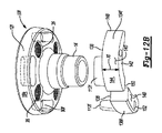
図11〜図128を参照すると、本教示にしたがった別のインプラントが図示され、全体的に10eという参照番号で識別されている。インプラント10eの構造及び機能は、以下で説明し及び/又は図中に示されているいずれかの例外を除いて、上述のインプラント10dの構造及び機能と類似又は同一であり得る。したがって、類似の特徴について再度詳述することはしない。以下では、及び図面中では、同じ構成要素を識別するために、同じ参照番号が使用されるが、修正されたこれらの構成要素を識別するためには、文字拡張部(すなわち「e」)を含む同じ参照番号が使用される。 With reference to FIGS. 11-128, another implant according to this teaching is illustrated and is generally identified by a reference number of 10e. The structure and function of the implant 10e can be similar or identical to the structure and function of the implant 10d described above, with the exception of any of those described below and / or shown in the drawings. Therefore, similar features will not be described in detail again. In the following, and in the drawings, the same reference numbers are used to identify the same components, but to identify these modified components, a character extension (ie, "e") is used. The same reference number is used, including.
インプラント10eは、隣接する孔36間に位置設定された複数の孔90を含むことができる。いくつかの構成において、孔90は、実質的に円形の断面領域を含むことができる(図11及び図12A)。しかしながら、孔90は本開示の範囲内で、他の断面形状を含み得ることが認識される。例えば、図12Bに図示されているように、いくつかの構成において、孔90fは、細長い又はインゲン豆形の断面を含むことができる。
The implant 10e can include a plurality of
図示されているように、一構成において、インプラント10eは、隣接する孔36の各対の間に位置設定された2つの孔90を含むことができる。この点において、孔90は、実質的に円形パターンを画定することができる。孔90、90fは、孔の断面積が関節面から骨係合面に向って増大するように、関節面20eと骨係合面22eとの間でテーパー(例えばモールス型テーパー)が付いていてもよい。
As shown, in one configuration, the implant 10e can include two
インプラント10eはさらに、第1のインサート134と第2のインサート136とを含むことができる。第1のインサート134は、インプラント係合表面138と、骨係合表面140と、半径方向内側表面142と、半径方向外側表面144と、を含むことができる。インプラント係合表面138及び骨係合表面140は、その間に延在する距離Xeを画定する。いくつかの構成において、距離Xeは、第1のインサート134が実質的にくさび形構成体を画定するように、インプラント係合表面138と骨係合表面140との間で変動し得る(図12A)。他の構成において、距離Xeは一定であり得る(図12B)。したがって、いくつかの構成では、第1のインサート134fは、実質的に矩形の断面を画定できる。
Implant 10e can further include a
インプラント係合表面138は、少なくとも1つのペグ112を含むことができる。いくつかの構成において、インプラント係合表面138は2つのペグ112を含み得る。ペグ112は、ペグ112の断面積が孔90の断面積に対応してペグ112と孔90との間の圧入係合を可能にするように、テーパー(例えばモールス型テーパー)が付けられていてもよい。この点において、いくつかの構成において、ペグ112は、実質的に円形の断面領域を含むことができる(図11及び図12A)。しかしながら、ペグ112は、孔90の形状に対応するように他の断面形状を含むこともできるという点が認識される。例えば、図12Bに図示されているように、いくつかの構成において、ペグ112fは、孔90fの形状と対応するように、細長い又はインゲン豆形の断面を含むことができる。
The
半径方向内側表面142は、第1のインサート134の第1及び第2の端部148、150から、及び、第1及び第2の端部148、150の間で、弓形に延在し得る。この点において、半径方向内側表面142は凹状であり得る。半径方向外側表面144は、半径方向内側表面142の反対側にあり得、第1及び第2の端部148、150から、及び、第1及び第2の端部148、150の間で、弓形に延在し得る。この点において、半径方向外側表面144は凸状であり得る。
The radial
第2のインサート136は、以下で説明し及び/又は図中に示されているいずれかの例外は除いて、以上で説明した第1のインサート134の構造及び機能と類似しているか又は同一であり得る。したがって、類似の特徴について、再度詳しく説明することはしない。以下で及び図面中では、同じ構成要素を識別するために、同じ参照番号が使用される。第2のインサート136は、インプラント係合表面138と骨係合表面140との間に延在する孔152を含むことができる。いくつかの構成において、孔152は、連続するペグ112の間に配置され得る。
The
図12A及び図128に図示されているように、組立てた構成において、本体12と第1及び第2のインサート134、136とは、実質的にくさび形のインプラント10eを画定する。ペグ112、112fは、本体12eの周囲表面18eが、第1及び第2のインサート134、136の半径方向外側表面144と実質的に整列されるか又は同一平面になるように、孔90、90f内に配置され得る。この点において、第1のインプラント134、134fの第1の端部148及び第2のインプラント136、136fの第2の端部150は、軸16を中心にして延在する角度θgを画定することができる。
As illustrated in FIGS. 12A and 128, in the assembled configuration, the
図13に図示されているように、インプラント10gのいくつかの構成において、第1及び/又は第2のインサート134、136のペグ112は、本体12fの孔90fの中に挿入され得る。同様にして、インサート134fは、ペグ112を含むことができる。細長い又は実質的にインゲン豆形の孔90f内に実質的に円筒形のペグ112を挿入することによって、第1のインサート134、134f及び/又は第2のインサート136、136fが本体12fに対して回転できるようにすることが可能であり、こうして、角度θgは調整可能になる。この点において、ペグ112は、孔90f内で滑動可能に、又は他の方法で移動可能に配置され得る。本体12fに対して第1のインサート134、134f及び/又は第2のインサート136、136fを回転させることで、インサート134、134f、136、136fを含めたインプラント10gが、骨のより大きい欠陥又は摩滅部分をカバーできるようにすることが可能である。
As illustrated in FIG. 13, in some configurations of the implant 10g, the
インプラント10、10a、10b、10c、10d、10e、10f及び10gの拡張された又はくさび形の構成体は、骨内の摩滅及び摩耗パターンを考慮に入れることによってインプラントの外科的移植を改善できる、ということが認識される。骨内の摩滅及び摩耗パターンを考慮に入れることは、骨移植片の必要性及び骨の過剰なリーマ加工を行う必要性を最小限に抑えるか又は無くするための一助となり得、これにより、外科的処置の時間は削減される一方、骨に対するインプラントの正確かつ安全な設置が保証される。
The expanded or wedge-shaped constructs of
実施形態の以上の記載は、例示及び説明を目的として提供されたものである。それは、網羅的であるように又は開示を限定するように意図されたものではない。特定の実施形態の個別の要素又は特徴は、概してその特定の実施形態に限定されず、該当する場合、具体的に示され又は説明されていない場合でも、互換性があり、選択された一実施形態において使用可能である。特定の実施形態の個別の要素又は特徴は、同様に、多くの方法で変形され得る。このような変形形態は、本開示からの逸脱としてみなされるべきものではなく、このような修正は全て、本開示の範囲内に含み入れられるように意図されている。 The above description of the embodiment is provided for the purpose of exemplification and explanation. It is not intended to be exhaustive or to limit disclosure. The individual elements or features of a particular embodiment are generally not limited to that particular embodiment and, where applicable, are compatible and selected, even if not specifically indicated or described. It can be used in the form. The individual elements or features of a particular embodiment can be similarly modified in many ways. Such variants should not be considered as deviations from this disclosure, and all such modifications are intended to be included within the scope of this disclosure.
例示的実施形態は、本開示が完璧なものとなるように提供され、当業者に対し完全に範囲を伝達する。本開示の実施形態を完全に理解できるようにするため、具体的構成要素、装置及び方法の例などの多くの具体的詳細が、明記されている。当業者にとっては、具体的詳細を利用する必要がないこと、多くの異なる形態で例示的実施形態を具体化できること、そして、そのいずれも本開示の範囲を限定するものとみなされるべきではないこと、は明白である。いくつかの例示的実施形態において、周知のプロセス、周知の装置構造及び周知の技術は詳細に説明されていない。 Illustrative embodiments are provided to complete this disclosure and fully communicate to those skilled in the art. In order to fully understand the embodiments of the present disclosure, many specific details such as examples of specific components, devices and methods are specified. For those skilled in the art, the need to utilize specific details, the ability to embody exemplary embodiments in many different forms, and none of which should be considered to limit the scope of this disclosure. , Is obvious. In some exemplary embodiments, well-known processes, well-known equipment structures and well-known techniques are not described in detail.
本明細書中で使用される用語は、特定の例示的実施形態を説明することのみを目的としたものであり、限定的であるようには意図されていない。本明細書中で使用されている単数形態「a」、「an」、及び「the」は、文脈上別段の明らかな指示がないかぎり、複数の形態も同様に含むように意図され得る。「備える(comprises)」、「備える(comprising)」、「含む」及び「有する」なる用語は、包含的であり、したがって、記された特徴、完成体、ステップ、動作、要素及び/又は構成要素の存在を規定するが、1つ以上の他の特徴、完成体、ステップ、動作、要素、構成要素及び/又はそれらの群の存在又は付加を除外するわけではない。本明細書中に記載の方法ステップ、プロセス及び動作は、実施順序として具体的に識別されているのでないかぎり、必ずしも、論述又は例示された特定の順序でそれらを実施することが求められるとみなされるべきものではない。追加の又は代替的なステップを利用できることも同様に理解すべきである。 The terms used herein are for the purpose of describing particular exemplary embodiments only and are not intended to be limiting. As used herein, the singular forms "a", "an", and "the" may be intended to include multiple forms as well, unless otherwise explicit in the context. The terms "comprises," "comprising," "including," and "having" are inclusive and are therefore described features, completeness, steps, actions, elements and / or components. It defines the existence of, but does not preclude the existence or addition of one or more other features, bodies, steps, actions, elements, components and / or groups thereof. The method steps, processes and operations described herein are not necessarily considered to be required to be performed in the particular order described or illustrated, unless specifically identified as the order of implementation. It shouldn't be. It should be understood as well that additional or alternative steps are available.
1つの要素又は層が、別の要素又は層に対して、「上にある」、「係合されている」、「連結されている」又は「結合されている」ものとして言及されている場合、それは、もう一方の要素又は層に対して、直接、上にある、係合されている、連結されている、又は結合されている可能性があり、又は、介在する要素又は層が存在し得る。対照的に、1つの要素が、別の要素又は層に対して、「直接上にある」、「直接係合されている」、「直接連結されている」、又は「直接結合されている」ものとして言及されている場合、介在する要素又は層は不在であり得る。要素間の関係を説明するために使用される他の用語も、同じように解釈されるべきである(例えば「〜の間」対「直接〜の間」、「〜に隣接する」対「直接〜に隣接する」等)。本明細書中で使用される「及び/又は」なる用語は、付随する列挙された事項の1つ以上のものの任意の及び全ての組合せを含む。 When one element or layer is referred to as "on", "engaged", "connected" or "bonded" to another element or layer , It may have elements or layers directly above, engaged, connected, or connected to the other element or layer, or there are intervening elements or layers. obtain. In contrast, one element is "directly above", "directly engaged", "directly linked", or "directly coupled" to another element or layer. Intervening elements or layers can be absent when referred to as. Other terms used to describe the relationships between the elements should be interpreted in the same way (eg, "between" vs. "directly between", "adjacent to" vs. "directly". Adjacent to "etc.). As used herein, the term "and / or" includes any and all combinations of one or more of the accompanying enumerated matters.
第1の、第2の、第3のなどの用語は本明細書において、さまざまな要素、構成要素、領域、層及び/又は区分を説明するために使用され得るものの、これらの要素、構成要素、領域、層及び/又は区分は、これらの用語により限定されるべきではない。これらの用語は、1つの要素、構成要素、領域、層又は区分を、別の領域、層又は区分から区別するためにのみ使用することができる。「第1の」、「第2の」及び他の数詞などの用語が本明細書中で使用される場合、それらは、文脈により明らかに指示されているのでないかぎり、1つの順番又は順序を暗に意味するわけではない。したがって、以下で論述する第1の要素、構成要素、領域、層又は区分は、例示的実施形態の教示から逸脱することなく、第2の要素、構成要素、領域、層又は区分と呼ぶことができる。 Although terms such as first, second, third, etc. may be used herein to describe various elements, components, areas, layers and / or compartments, these elements, components, etc. , Regions, layers and / or divisions should not be limited by these terms. These terms can only be used to distinguish one element, component, region, layer or division from another region, layer or division. When terms such as "first," "second," and other numerals are used herein, they are in one order or order, unless explicitly indicated by the context. It doesn't mean implicitly. Therefore, the first element, component, region, layer or division discussed below may be referred to as the second element, component, region, layer or division without departing from the teachings of the exemplary embodiments. it can.
「内部」、「外部」、「下方(beneath)」、「下方(below)」、「下方(lower)」、「上方(above)」、「上方(upper)」などの空間的に相対的な用語は、本明細書において、図中に示されているように、別の1つ若しくは複数の要素又は1つ若しくは複数の特徴に対する1つの要素又は特徴の関係を描写するため、説明を容易にする目的で使用され得る。空間的に相対的な用語は、図中に描かれた向きに加えて、使用又は動作中における装置の異なる向きを包含するように意図され得る。例えば、図中の装置が反転された場合、このとき他の要素又は特徴の「下方(below)」又は「下方(beneath)」として描写された要素は、他の要素又は特徴の「上方」に向けられていることになる。したがって、例示的用語「下方」は、上方及び下方の両方の向きを包含し得る。装置は、他の形で(90度回転されて、又は他の向きで)配向され得、空間的に相対的な記述子は、本明細書において相応して解釈されて使用され得る。 Spatial relatives such as "inside", "outside", "beneath", "below", "lower", "above", "upper" The terminology, as shown herein, is easy to explain because it describes the relationship of one element or feature to another one or more elements or one or more features. Can be used for the purpose of Spatial relative terms may be intended to include different orientations of the device during use or operation, in addition to the orientations depicted in the figure. For example, if the device in the figure is flipped, then the element depicted as "below" or "beneath" of the other element or feature will be "above" the other element or feature. It will be directed. Thus, the exemplary term "downward" can include both up and down orientations. The device can be oriented in other ways (rotated 90 degrees or in other orientations) and spatially relative descriptors can be interpreted and used accordingly herein.
特定の角度を説明するのに使用される「おおよそ」、「概して」、「約」及び「実質的に」なる用語は、規定された角度及び1から2度(1°〜2°)の範囲を包含するものとして理解されるべきである。 The terms "approximate," "generally," "about," and "substantially" used to describe a particular angle are defined angles and range from 1 to 2 degrees (1 ° to 2 °). Should be understood as embracing.
Claims (9)
ステム部であって、前記本体部から別個に形成され、かつ、前記本体部に対して取り付け可能であり、これによって、取り付けられたときに、当該ステム部が、前記本体部から長手軸に沿って延在する、ステム部と、を備え、
前記本体部は、関節面と、前記関節面とは反対の骨係合面と、を有し、
前記骨係合面の少なくとも一部分は、側面視において前記関節面の少なくとも周囲縁部に対して平行でない角度で配置されており、前記関節面の前記周囲縁部は、前記長手軸に対して実質的に垂直な平面を画定し、
前記骨係合面は、凸状である骨係合表面を含み、
前記骨係合表面は、前記骨係合面の全体に拡がっており、
前記骨係合表面は、第1の部分及び第2の部分を含み、
前記第1の部分は、側面視において前記関節面の少なくとも前記周囲縁部に対して第1の角度α1で配置された第1の周囲縁部であって、前記第1の角度α1が、ゼロ度でない、第1の周囲縁部を有し、
前記第2の部分は、側面視において前記関節面の少なくとも前記周囲縁部に対して第2の異なる角度α2で配置された第2の周囲縁部であって、前記第2の角度α2が、ゼロ度である、第2の周囲縁部を有し、
前記本体部は、前記関節面と前記骨係合面との間で前記本体部を通って延びる少なくとも1つの孔を含み、
前記骨係合表面の前記第1の部分は、近位端と遠位端との間で前記長手軸に対して平行な方向で延在する複数の突出部であって、当該複数の突出部の前記遠位端及び前記周囲縁部がくさび形の構成体を画定する、複数の突出部を含み、前記骨係合表面の前記第2の部分は、突出部を含まない、関節窩インプラント。 With the main body
It is a stem portion, which is formed separately from the main body portion and can be attached to the main body portion, whereby when attached, the stem portion is formed from the main body portion along a longitudinal axis. With a stem part that extends
The main body portion has a joint surface and a bone engaging surface opposite to the joint surface.
At least a portion of the bone engaging surface is arranged at an angle not parallel to at least the peripheral edge of the joint surface in lateral view, and the peripheral edge of the joint surface is substantially relative to the longitudinal axis. Demarcate a plane that is perpendicular to the
The bone engaging surface includes a convex bone engaging surface.
The bone engaging surface extends over the entire bone engaging surface .
The bone engaging surface includes a first portion and a second portion.
The first portion is a first peripheral edge portion arranged at a first angle α1 with respect to at least the peripheral edge portion of the joint surface in a lateral view, and the first angle α1 is zero. Has a first peripheral edge, not a degree,
The second portion is a second peripheral edge portion arranged at a second different angle α2 with respect to at least the peripheral edge portion of the joint surface in a lateral view, and the second angle α2 is. Has a second peripheral edge, which is zero degrees,
The body portion comprises at least one hole extending through the body portion between the joint surface and the bone engaging surface.
The first portion of the bone engaging surface is a plurality of protrusions extending in a direction parallel to the longitudinal axis between the proximal end and the distal end, and the plurality of protrusions. A glenoid implant comprising a plurality of protrusions , wherein the distal end and the peripheral edge of the bone define a wedge-shaped structure, and the second portion of the bone engaging surface is free of protrusions.
本体部であって、前記ステム部から別個に形成され、かつ、前記ステム部に対して取り付け可能であり、これによって、取り付けられたときに、当該本体部が、前記ステム部の近位端に支持される、本体部と、
を備え、
前記本体部は、関節面、前記関節面とは反対の骨係合面、及び前記関節面と前記骨係合面との間に延在する周囲側壁を含み、
前記周囲側壁は、前記長手軸に対して平行な奥行を有し、
前記周囲側壁の少なくとも一部分は、側面視において前記長手軸に対して垂直な方向で奥行が増大し、
前記骨係合面は、凸状である骨係合表面を含み、
前記骨係合表面は、前記骨係合面の全体に拡がっており、
前記本体部は、前記関節面と前記骨係合面との間で前記本体部を通って延びる少なくとも1つの孔を含み、
前記骨係合面は、近位端と遠位端との間で前記長手軸に対して平行な方向で延在する複数の突出部であって、当該複数の突出部の前記遠位端及び前記関節面の周囲縁部がくさび形の構成体を画定する、複数の突出部を含む第1の部分と、突出部を含まない第2の部分と、を有する、関節窩インプラント。 A stem part with a longitudinal axis and
A body portion that is formed separately from the stem portion and can be attached to the stem portion so that when attached, the body portion is located at the proximal end of the stem portion. The main body that is supported,
With
The body includes a joint surface, a bone engaging surface opposite the joint surface, and a peripheral side wall extending between the joint surface and the bone engaging surface.
The peripheral side wall has a depth parallel to the longitudinal axis and has a depth parallel to the longitudinal axis.
At least a part of the peripheral side wall increases in depth in a direction perpendicular to the longitudinal axis in side view.
The bone engaging surface includes a convex bone engaging surface.
The bone engaging surface extends over the entire bone engaging surface .
The body portion comprises at least one hole extending through the body portion between the joint surface and the bone engaging surface.
The bone engaging surface is a plurality of protrusions extending in a direction parallel to the longitudinal axis between the proximal end and the distal end, and the distal end and the distal end of the plurality of protrusions. A glenoid implant having a first portion with a plurality of protrusions and a second portion without protrusions , wherein the peripheral edge of the articular surface defines a wedge-shaped structure.
ステム部であって、前記本体部から別個に形成され、かつ、前記本体部に対して取り付け可能であり、これによって、取り付けられたときに、当該ステム部が、前記本体部から長手軸に沿って延在する、ステム部と、
を備え、
前記本体部は、関節面を有し、
前記関節面の少なくとも一部分は、凹状かつ実質的に球状である表面を含み、
前記本体部は、前記関節面とは反対の骨係合面を有し、
前記骨係合面は、凸状である骨係合表面を含み、
前記骨係合表面は、前記骨係合面の全体に拡がっており、
前記骨係合表面は、側面視において前記関節面の少なくとも周囲縁部に対して第1の角度α1で配置された第1の周囲縁部を有しかつ180°に実質的に等しい角度θだけ前記長手軸を中心にして延びる、第1の部分を含み、前記関節面の前記周囲縁部は、前記長手軸に対して実質的に垂直な平面を画定し、前記第1の角度α1が、ゼロ度でなく、
前記骨係合表面は、側面視において前記関節面の少なくとも前記周囲縁部に対して第2の異なる角度α2で配置された第2の周囲縁部を有する、第2の部分を更に含み、前記第2の角度α2が、ゼロ度であり、
前記骨係合面の少なくとも一部分は、側面視において前記関節面の少なくとも前記周囲縁部に対して平行でない角度で配置されており、
前記本体部は、前記関節面と前記骨係合面との間で前記本体部を通って延びる少なくとも1つの孔を含み、
前記骨係合表面の前記第1の部分は、近位端と遠位端との間で前記長手軸に対して平行な方向で延在する複数の突出部であって、当該複数の突出部の前記遠位端及び前記周囲縁部がくさび形の構成体を画定する、複数の突出部を含み、前記骨係合表面の前記第2の部分は、突出部を含まない、関節窩インプラント。 With the main body
It is a stem portion, which is formed separately from the main body portion and can be attached to the main body portion, whereby when attached, the stem portion is formed from the main body portion along a longitudinal axis. With the stem part that extends
With
The main body has an articular surface and has an articular surface.
At least a portion of the articular surface comprises a concave and substantially spherical surface.
The body portion has a bone engaging surface opposite to the joint surface and has a bone engaging surface.
The bone engaging surface includes a convex bone engaging surface.
The bone engaging surface extends over the entire bone engaging surface .
The bone engaging surface has a first peripheral edge located at a first angle α1 with respect to at least the peripheral edge of the joint surface in lateral view and is only at an angle θ substantially equal to 180 °. The peripheral edge of the articular surface, including a first portion extending about the longitudinal axis, defines a plane substantially perpendicular to the longitudinal axis, with the first angle α1 being Not zero degrees
The bone engaging surface further comprises a second portion having a second peripheral edge arranged at at least the peripheral edge of the joint surface at a second different angle α2 in lateral view. The second angle α2 is zero degree,
At least a portion of the bone engaging surface is arranged at an angle not parallel to at least the peripheral edge of the joint surface in lateral view.
The body portion comprises at least one hole extending through the body portion between the joint surface and the bone engaging surface.
The first portion of the bone engaging surface is a plurality of protrusions extending in a direction parallel to the longitudinal axis between the proximal end and the distal end, and the plurality of protrusions. A glenoid implant comprising a plurality of protrusions , wherein the distal end and the peripheral edge of the bone define a wedge-shaped structure, and the second portion of the bone engaging surface is free of protrusions.
Applications Claiming Priority (3)
| Application Number | Priority Date | Filing Date | Title |
|---|---|---|---|
| US14/459,935 | 2014-08-14 | ||
| US14/459,935 US9844440B2 (en) | 2014-08-14 | 2014-08-14 | Glenoid implant |
| PCT/US2015/044448 WO2016025378A1 (en) | 2014-08-14 | 2015-08-10 | Glenoid implant |
Publications (3)
| Publication Number | Publication Date |
|---|---|
| JP2017523872A JP2017523872A (en) | 2017-08-24 |
| JP2017523872A5 JP2017523872A5 (en) | 2018-07-12 |
| JP6791843B2 true JP6791843B2 (en) | 2020-11-25 |
Family
ID=53836915
Family Applications (1)
| Application Number | Title | Priority Date | Filing Date |
|---|---|---|---|
| JP2017508061A Active JP6791843B2 (en) | 2014-08-14 | 2015-08-10 | Glenoid implant |
Country Status (7)
| Country | Link |
|---|---|
| US (4) | US9844440B2 (en) |
| EP (1) | EP3179962B1 (en) |
| JP (1) | JP6791843B2 (en) |
| CN (1) | CN107072791B (en) |
| AU (1) | AU2015302017B2 (en) |
| CA (1) | CA2957682C (en) |
| WO (1) | WO2016025378A1 (en) |
Families Citing this family (41)
| Publication number | Priority date | Publication date | Assignee | Title |
|---|---|---|---|---|
| US8778028B2 (en) | 2005-02-25 | 2014-07-15 | Shoulder Innovations, Inc. | Methods and devices for less invasive glenoid replacement |
| US20230080207A1 (en) | 2005-02-25 | 2023-03-16 | Shoulder Innovations, Inc. | Methods and devices for less invasive glenoid replacement |
| FR2955247B1 (en) | 2010-01-21 | 2013-04-26 | Tornier Sa | GLENOIDAL COMPONENT OF SHOULDER PROSTHESIS |
| FR2971144A1 (en) * | 2011-02-08 | 2012-08-10 | Tornier Sa | GLENOIDAL IMPLANT FOR SHOULDER PROSTHESIS AND SURGICAL KIT |
| WO2015103090A1 (en) * | 2014-01-03 | 2015-07-09 | Tornier, Inc. | Reverse shoulder systems |
| US10575968B2 (en) | 2014-05-16 | 2020-03-03 | Howmedica Osteonics Corp. | Guides for fracture system |
| US9681960B2 (en) | 2014-05-16 | 2017-06-20 | Howmedica Osteonics Corp. | Guides for fracture system |
| US9844440B2 (en) | 2014-08-14 | 2017-12-19 | Biomet Manufacturing, Llc | Glenoid implant |
| GB201505212D0 (en) * | 2015-03-26 | 2015-05-13 | Imp Innovations Ltd | Prosthetic glenoid component |
| AU2016250842B2 (en) | 2015-04-24 | 2020-05-07 | Biomet Manufacturing, Llc | Patient-specific augmented glenoid systems |
| US11090161B2 (en) | 2016-03-25 | 2021-08-17 | Howmedica Osteonics Corp. | Surgical instrumentation assembly, set and surgical shoulder repair method |
| US10226350B2 (en) * | 2016-07-15 | 2019-03-12 | Encore Medical L.P. | Glenosphere with hood for augmented fixation and related methods |
| AU2018210170C1 (en) | 2017-01-19 | 2022-12-15 | Encore Medical, L.P. (D/B/A Djo Surgical) | Shoulder implant components |
| US11510785B2 (en) * | 2017-04-25 | 2022-11-29 | Biomet Manufacturing, Llc | Augmented glenoid with groove |
| EP3403617B1 (en) | 2017-05-19 | 2020-03-18 | Tornier | Augment insert, shoulder prosthesis and kit comprising the augment insert |
| EP3412251B1 (en) * | 2017-06-08 | 2021-12-15 | MAKO Surgical Corp. | Robotic bone preparation for increasing implant contact surface area |
| EP4039231A1 (en) * | 2017-06-29 | 2022-08-10 | Encore Medical, L.P. (D/B/A DJO Surgical) | Glenosphere with inserts for augmented fixation and related methods |
| AU2019263063A1 (en) * | 2018-04-30 | 2020-12-10 | Shoulder Innovations, Inc. | Inset/onlay glenoid, porous coated convertible glenoid, and humeral heads with textured undersides |
| CN112423687A (en) * | 2018-07-10 | 2021-02-26 | 阿德勒奥尔托股份公司 | Device for promoting the formation of new bone tissue |
| WO2020023971A1 (en) * | 2018-07-27 | 2020-01-30 | Ignite Orthopedics Llc | Implants, systems and methods of using the same |
| CA3107924A1 (en) * | 2018-07-27 | 2020-01-30 | Ignite Orthopedics Llc | Implants, systems and methods of using the same |
| CA3107923A1 (en) | 2018-07-27 | 2020-01-30 | Ignite Orthopedics Llc | Implants, systems and methods of using the same |
| WO2020159864A1 (en) * | 2019-01-28 | 2020-08-06 | Encore Medical L.P. (D/B/A Djo Surgical) | Glenoid implant |
| EP3937857A4 (en) * | 2019-03-11 | 2022-11-02 | Shoulder Innovations, Inc. | Total reverse shoulder systems and methods |
| CN114364349A (en) * | 2019-04-25 | 2022-04-15 | 安可医疗有限公司(以Djo外科名义) | Shoulder socket implant |
| AU2020204539A1 (en) * | 2019-07-12 | 2021-01-28 | Howmedica Osteonics Corp. | Augmented glenoid design |
| AU2020207869A1 (en) * | 2019-08-01 | 2021-02-18 | Howmedica Osteonics Corp. | Hybrid metal-backed glenoid component |
| AU2020328486B2 (en) | 2019-08-09 | 2024-01-25 | Howmedica Osteonics Corp. | Apparatuses and methods for implanting glenoid prostheses |
| US11426285B2 (en) | 2019-09-05 | 2022-08-30 | Howmedica Osteonics Corp. | Truss glenoid augment |
| EP4048159A4 (en) * | 2019-10-24 | 2023-09-13 | Ignite Orthopedics LLC | Orthopedic implant system with augmentation device and methods of use |
| IT201900021432A1 (en) * | 2019-11-18 | 2021-05-18 | Limacorporate Spa | Glenoid component for shoulder prosthesis and relative shoulder prosthesis |
| US11432935B2 (en) * | 2020-04-01 | 2022-09-06 | Arthrex, Inc. | Orthopaedic implants including peripheral aperture arrangements |
| WO2021202101A1 (en) | 2020-04-01 | 2021-10-07 | Arthrex, Inc. | Systems and methods of forming orthopaedic implants including printed augments |
| US11850158B2 (en) * | 2020-05-26 | 2023-12-26 | Howmedica Osteonics Corp. | Orthopedic surgical implant device with porous material and fluid channels for cleaning the porous material |
| US11737883B2 (en) | 2021-03-02 | 2023-08-29 | Arthrex, Inc. | Orthopaedic implants including breakaway fastener |
| IT202100005870A1 (en) * | 2021-03-12 | 2022-09-12 | Limacorporate Spa | SHOULDER PROSTHESIS |
| US11819415B2 (en) | 2021-04-02 | 2023-11-21 | Arthrex, Inc. | Orthopaedic implant systems including internal networks and methods of repair |
| KR20230064204A (en) * | 2021-11-03 | 2023-05-10 | 주식회사 코렌텍 | Glenoid baseplate and Manufacturing Method thereof |
| KR20230064220A (en) * | 2021-11-03 | 2023-05-10 | 주식회사 코렌텍 | Glenoid baseplate |
| KR20230064181A (en) * | 2021-11-03 | 2023-05-10 | 주식회사 코렌텍 | Glenoid baseplate |
| CN117159234B (en) * | 2023-11-03 | 2024-03-15 | 北京爱康宜诚医疗器材有限公司 | Joint implant |
Family Cites Families (27)
| Publication number | Priority date | Publication date | Assignee | Title |
|---|---|---|---|---|
| DE3813944A1 (en) | 1988-04-26 | 1989-11-09 | S & G Implants Gmbh | ENDOPROTHESIS FOR A JOINT |
| FR2704747B1 (en) | 1993-05-06 | 1995-07-21 | Medinov Sa | Support intended to receive a glenoid organ. |
| US5800551A (en) | 1997-03-10 | 1998-09-01 | Biomet, Inc. | Apparatus and method for shoulder arthroplasty |
| FR2780635B1 (en) | 1998-07-06 | 2000-10-20 | Tornier Sa | DEVICE FOR FIXING A PLASTIC INSERT |
| FR2802799B1 (en) | 1999-12-23 | 2002-08-16 | Depuy France | SHOULDER PROSTHESIS KIT |
| US6699289B2 (en) | 2001-12-31 | 2004-03-02 | Depuy Orthopaedics, Inc. | Augmented glenoid component having an interrupted surface and associated method for securing the augmented glenoid component to a glenoid surface of a scapula |
| ATE503442T1 (en) | 2004-05-19 | 2011-04-15 | Zimmer Gmbh | GLENOID ANCHORAGE |
| US8303665B2 (en) * | 2004-06-15 | 2012-11-06 | Tornier Sas | Glenoidal component, set of such components and shoulder prosthesis incorporating such a glenoidal component |
| US7892287B2 (en) * | 2004-09-27 | 2011-02-22 | Depuy Products, Inc. | Glenoid augment and associated method |
| CA2627551A1 (en) * | 2005-10-26 | 2007-05-03 | Exactech, Inc. | Apparatus and method to obtain bone fixation |
| US20070161985A1 (en) * | 2005-12-05 | 2007-07-12 | Kentomia, Llc . | Screws configured to engage bones, and methods of attaching implants to skeletal regions |
| US8425614B2 (en) * | 2006-03-20 | 2013-04-23 | Biomet Manufacturing Corp. | Modular center pegged glenoid |
| FR2899790B1 (en) * | 2006-04-13 | 2008-06-13 | Tornier Sas | GLENOIDAL COMPONENT FOR TOTAL SHOULDER PROSTHESIS, SET OF SUCH COMPONENTS, AND TOTAL SHOULDER PROSTHESIS COMPRISING SUCH A COMPONENT |
| EP2057970B1 (en) * | 2007-11-07 | 2016-01-06 | Arthrex, Inc. | Hybrid glenoid for shoulder arthroplasty |
| US8043375B2 (en) * | 2008-03-06 | 2011-10-25 | MoiRai Orthopaedic, LLC | Cartilage implants |
| US20100161066A1 (en) | 2008-12-23 | 2010-06-24 | Depuy Products, Inc. | Shoulder Prosthesis having Augmented Metaglene Component for Use in Rotator Cuff Deficient Shoulder |
| US20100217399A1 (en) * | 2009-02-22 | 2010-08-26 | Groh Gordon I | Base plate system for shoulder arthroplasty and method of using the same |
| US9545311B2 (en) * | 2009-03-05 | 2017-01-17 | Tornier, Inc. | Glenoid implant anchor post |
| US9833327B2 (en) * | 2009-03-20 | 2017-12-05 | DePuy Synthes Products, Inc. | Glenoid component for use in shoulder arthroplasty |
| FR2964857B1 (en) * | 2010-09-17 | 2013-07-05 | Marc Duport | MODULAR CUP OF SHOULDER PROSTHESIS |
| US9226830B2 (en) * | 2011-03-18 | 2016-01-05 | DePuy Synthes Products, Inc. | Device and method for retroversion correction for shoulder arthroplasty |
| US8764836B2 (en) * | 2011-03-18 | 2014-07-01 | Lieven de Wilde | Circular glenoid method for shoulder arthroplasty |
| US8992623B2 (en) * | 2011-03-25 | 2015-03-31 | Zimmer Gmbh | Shoulder prosthesis |
| US8721728B2 (en) * | 2011-04-27 | 2014-05-13 | Biomet Manufacturing, Llc | Modular glenoid prosthesis |
| EP2749255A1 (en) * | 2012-12-27 | 2014-07-02 | Zimmer GmbH | Shoulder prosthesis and components thereof |
| US10028838B2 (en) * | 2014-06-30 | 2018-07-24 | Tornier, Inc. | Augmented glenoid components and devices for implanting the same |
| US9844440B2 (en) | 2014-08-14 | 2017-12-19 | Biomet Manufacturing, Llc | Glenoid implant |
-
2014
- 2014-08-14 US US14/459,935 patent/US9844440B2/en active Active
-
2015
- 2015-08-10 EP EP15750604.9A patent/EP3179962B1/en active Active
- 2015-08-10 AU AU2015302017A patent/AU2015302017B2/en active Active
- 2015-08-10 JP JP2017508061A patent/JP6791843B2/en active Active
- 2015-08-10 WO PCT/US2015/044448 patent/WO2016025378A1/en active Application Filing
- 2015-08-10 CA CA2957682A patent/CA2957682C/en active Active
- 2015-08-10 CN CN201580050317.9A patent/CN107072791B/en active Active
-
2017
- 2017-11-16 US US15/815,462 patent/US10258478B2/en active Active
-
2019
- 2019-01-23 US US16/255,274 patent/US11033400B2/en active Active
-
2021
- 2021-05-12 US US17/318,623 patent/US20210259845A1/en active Pending
Also Published As
| Publication number | Publication date |
|---|---|
| US20180071104A1 (en) | 2018-03-15 |
| AU2015302017B2 (en) | 2018-07-19 |
| US20210259845A1 (en) | 2021-08-26 |
| CN107072791B (en) | 2019-08-09 |
| US9844440B2 (en) | 2017-12-19 |
| CA2957682A1 (en) | 2016-02-18 |
| US10258478B2 (en) | 2019-04-16 |
| EP3179962B1 (en) | 2021-03-24 |
| US20160045323A1 (en) | 2016-02-18 |
| EP3179962A1 (en) | 2017-06-21 |
| WO2016025378A1 (en) | 2016-02-18 |
| US20190151106A1 (en) | 2019-05-23 |
| JP2017523872A (en) | 2017-08-24 |
| CA2957682C (en) | 2018-12-04 |
| US11033400B2 (en) | 2021-06-15 |
| AU2015302017A1 (en) | 2017-03-30 |
| CN107072791A (en) | 2017-08-18 |
Similar Documents
| Publication | Publication Date | Title |
|---|---|---|
| JP6791843B2 (en) | Glenoid implant | |
| JP7314268B2 (en) | Implants, systems and methods of using same | |
| US20200155170A1 (en) | Flexible bone reamer | |
| US9295556B2 (en) | Minimally invasive total hip replacement | |
| JP6276510B2 (en) | Joint implant test component | |
| ES2920883T3 (en) | Retroversion Correction Device for Shoulder Arthroplasty | |
| US10512543B2 (en) | Components for artificial joints | |
| US8048161B2 (en) | Hybrid glenoid for shoulder arthroplasty | |
| JP7377864B2 (en) | Implants, systems and how to use them | |
| US20150272741A1 (en) | Press-fit glenoid with peripheral compression pegs | |
| US8366784B2 (en) | Distal radioulnar joint device | |
| US8900318B2 (en) | Implantable hallux joint assembly with spherical inter-support | |
| WO2018200101A1 (en) | Augmented glenoid with groove | |
| JP2019531131A (en) | Artificial hip joint stem and stem installation method | |
| JP2023502566A (en) | Glenoid components for shoulder prostheses and related shoulder prostheses | |
| KR20130093613A (en) | Acetabular cup prosthesis | |
| US10709562B2 (en) | Devices, apparatuses, kits, and methods for anchoring a suture to a bone | |
| CA3144607A1 (en) | Distal radioulnar joint prosthesis system and method of use | |
| EP3005987B1 (en) | Rotatable reverse metaglene assembly |
Legal Events
| Date | Code | Title | Description |
|---|---|---|---|
| A521 | Request for written amendment filed |
Free format text: JAPANESE INTERMEDIATE CODE: A523 Effective date: 20180529 |
|
| A621 | Written request for application examination |
Free format text: JAPANESE INTERMEDIATE CODE: A621 Effective date: 20180529 |
|
| A871 | Explanation of circumstances concerning accelerated examination |
Free format text: JAPANESE INTERMEDIATE CODE: A871 Effective date: 20180529 |
|
| A975 | Report on accelerated examination |
Free format text: JAPANESE INTERMEDIATE CODE: A971005 Effective date: 20180619 |
|
| A131 | Notification of reasons for refusal |
Free format text: JAPANESE INTERMEDIATE CODE: A131 Effective date: 20180626 |
|
| A521 | Request for written amendment filed |
Free format text: JAPANESE INTERMEDIATE CODE: A523 Effective date: 20180926 |
|
| A02 | Decision of refusal |
Free format text: JAPANESE INTERMEDIATE CODE: A02 Effective date: 20190108 |
|
| A521 | Request for written amendment filed |
Free format text: JAPANESE INTERMEDIATE CODE: A523 Effective date: 20190426 |
|
| C60 | Trial request (containing other claim documents, opposition documents) |
Free format text: JAPANESE INTERMEDIATE CODE: C60 Effective date: 20190426 |
|
| A911 | Transfer to examiner for re-examination before appeal (zenchi) |
Free format text: JAPANESE INTERMEDIATE CODE: A911 Effective date: 20190514 |
|
| C21 | Notice of transfer of a case for reconsideration by examiners before appeal proceedings |
Free format text: JAPANESE INTERMEDIATE CODE: C21 Effective date: 20190521 |
|
| A912 | Re-examination (zenchi) completed and case transferred to appeal board |
Free format text: JAPANESE INTERMEDIATE CODE: A912 Effective date: 20190607 |
|
| C211 | Notice of termination of reconsideration by examiners before appeal proceedings |
Free format text: JAPANESE INTERMEDIATE CODE: C211 Effective date: 20190611 |
|
| C22 | Notice of designation (change) of administrative judge |
Free format text: JAPANESE INTERMEDIATE CODE: C22 Effective date: 20200225 |
|
| C22 | Notice of designation (change) of administrative judge |
Free format text: JAPANESE INTERMEDIATE CODE: C22 Effective date: 20200414 |
|
| C22 | Notice of designation (change) of administrative judge |
Free format text: JAPANESE INTERMEDIATE CODE: C22 Effective date: 20200421 |
|
| C13 | Notice of reasons for refusal |
Free format text: JAPANESE INTERMEDIATE CODE: C13 Effective date: 20200512 |
|
| C302 | Record of communication |
Free format text: JAPANESE INTERMEDIATE CODE: C302 Effective date: 20200807 |
|
| A521 | Request for written amendment filed |
Free format text: JAPANESE INTERMEDIATE CODE: A523 Effective date: 20200812 |
|
| C23 | Notice of termination of proceedings |
Free format text: JAPANESE INTERMEDIATE CODE: C23 Effective date: 20200901 |
|
| C03 | Trial/appeal decision taken |
Free format text: JAPANESE INTERMEDIATE CODE: C03 Effective date: 20201006 |
|
| C30A | Notification sent |
Free format text: JAPANESE INTERMEDIATE CODE: C3012 Effective date: 20201006 |
|
| A61 | First payment of annual fees (during grant procedure) |
Free format text: JAPANESE INTERMEDIATE CODE: A61 Effective date: 20201105 |
|
| R150 | Certificate of patent or registration of utility model |
Ref document number: 6791843 Country of ref document: JP Free format text: JAPANESE INTERMEDIATE CODE: R150 |
|
| R250 | Receipt of annual fees |
Free format text: JAPANESE INTERMEDIATE CODE: R250 |