JP6790629B2 - Driving machine - Google Patents
Driving machine Download PDFInfo
- Publication number
- JP6790629B2 JP6790629B2 JP2016177407A JP2016177407A JP6790629B2 JP 6790629 B2 JP6790629 B2 JP 6790629B2 JP 2016177407 A JP2016177407 A JP 2016177407A JP 2016177407 A JP2016177407 A JP 2016177407A JP 6790629 B2 JP6790629 B2 JP 6790629B2
- Authority
- JP
- Japan
- Prior art keywords
- stopper
- pressing member
- magazine
- driving machine
- moving
- Prior art date
- Legal status (The legal status is an assumption and is not a legal conclusion. Google has not performed a legal analysis and makes no representation as to the accuracy of the status listed.)
- Active
Links
Images


Description
本開示は、射出部の止具を打撃部で打撃する打込機に関する。 The present disclosure relates to a driving machine that strikes a stopper of an injection portion with a striking portion.
射出部の止具を打撃部で打撃する打込機の例が、特許文献1に記載されている。特許文献1に記載された打込機は、射出部と、射出部に止具を送るマガジンと、射出部にある止具を打撃する打撃部と、打撃部を内蔵した動力部と、を有する。動力部は、ハンドルと、起動スイッチと、トリガと、起動レバーと、を有する。起動レバーは往復動可能であり、起動レバーは、上部起動レバー及び下部起動レバーを含む。上部起動レバーは引掛けレバーを有する。マガジンは、止具を送るフィーダを備え、フィーダは係合部を有する。 Patent Document 1 describes an example of a driving machine that strikes a stopper of an injection portion with a striking portion. The driving machine described in Patent Document 1 has an injection portion, a magazine for sending a stopper to the injection portion, a striking portion for striking the stopper in the injection portion, and a power unit having a built-in striking portion. .. The power unit has a handle, a start switch, a trigger, and a start lever. The start lever is reciprocating, and the start lever includes an upper start lever and a lower start lever. The upper start lever has a hook lever. The magazine comprises a feeder that feeds the stopper, which has an engaging portion.
特許文献1に記載された打込機は、マガジン内に止具が十分残っている時は、係合部と引掛けレバーとは係合しない。このため、上部起動レバーと下部起動レバーとが係合され、使用者が下部起動レバーを被打込材に押し付け、かつ、トリガを操作すると起動スイッチをオンできる。つまり、打込機は止具を打撃できる。 The driving machine described in Patent Document 1 does not engage the engaging portion and the hooking lever when a sufficient number of fasteners remain in the magazine. Therefore, the upper start lever and the lower start lever are engaged, and the start switch can be turned on when the user presses the lower start lever against the material to be driven and operates the trigger. That is, the driving machine can hit the stopper.
これに対して、マガジン内の止具が設定数以下になると、係合部が引掛けレバーに接触し、引掛けレバーを押し下げる。すると、上部起動レバーと下部起動レバーとが切り離された状態になる。このため、使用者が下部起動レバーを被打込材に押し付け、かつ、トリガを操作しても、起動スイッチをオンすることができない。つまり、打込機は起動しない。したがって、使用者は、打込機の空打ち防止が効いていることを認識できる。 On the other hand, when the number of fasteners in the magazine becomes less than the set number, the engaging portion contacts the hook lever and pushes down the hook lever. Then, the upper start lever and the lower start lever are separated from each other. Therefore, even if the user presses the lower start lever against the material to be driven and operates the trigger, the start switch cannot be turned on. That is, the driving machine does not start. Therefore, the user can recognize that the hitting prevention of the driving machine is effective.
釘打機における空打ち防止機構の上記とは別の方式として、起動レバー、つまり、押し付け部材の動きを規制する方式が考えられる。このような構造を想定した場合、上記従来技術と同様に、釘送り機構と押し付け部材との干渉による空打ち問題が発生し、回避する構造が必要となる。釘送り機構は、フィーダと係合部である。 As a method different from the above-mentioned method of the blank hitting prevention mechanism in the nailing machine, a method of restricting the movement of the starting lever, that is, the pressing member can be considered. When such a structure is assumed, a structure for avoiding a blank driving problem due to interference between the nail feeding mechanism and the pressing member is required as in the above-mentioned conventional technique. The nail feed mechanism is a feeder and an engaging portion.
本開示の目的は、マガジンに収容されている止具を射出部に送る動作を、円滑に行うことで空打ちを防止できる打込機を提供することにある。 An object of the present disclosure is to provide a driving machine capable of preventing a blank shot by smoothly performing an operation of sending a stopper housed in a magazine to an injection unit.
一実施形態の打込機は、止具を保持するマガジンと、前記マガジンから前記止具が送られる射出部と、前記射出部に送られた前記止具を打撃して被打込材に打ち込む打撃部と、を備えた打込機であって、前記射出部に設けられ、かつ、前記被打込材に押し付けられると前記射出部に対して移動する押し付け部材と、前記マガジンに設けられ、かつ、前記射出部に近づく向きで移動して前記止具を前記射出部に送るフィーダと、前記マガジンに対して前記射出部に近づく向きで移動可能に設けられ、かつ、前記押し付け部材に係合及び解放が可能なストッパと、前記フィーダを前記射出部に近づける向きで付勢する付勢部材と、前記フィーダの移動力を前記ストッパに伝達する移動力伝達部材と、を有し、前記ストッパは、前記マガジンが保持する前記止具の数が所定数以上であると、前記押し付け部材から解放されて前記押し付け部材の移動を許容し、前記ストッパは、前記マガジンが保持する前記止具の数が所定数未満であると、前記押し付け部材に係合して前記押し付け部材の移動を防止し、前記フィーダは、前記押し付け部材が前記被打込材に押し付けられ、かつ、前記ストッパが前記押し付け部材に接触して前記ストッパの移動が阻害されている場合に、前記止具を前記射出部に送り、前記移動力伝達部材は、前記マガジンが保持する前記止具の数が所定数以上であると前記フィーダの移動力を前記ストッパに伝達せず、前記移動力伝達部材は、前記マガジンが保持する前記止具の数が所定数未満であると前記フィーダの移動力を前記ストッパに伝達する。 The driving machine of one embodiment strikes a magazine holding a stopper, an injection portion to which the stopper is sent from the magazine, and the stopper sent to the injection portion to drive the stopper into the material to be driven. A driving machine provided with a striking portion, which is provided on the injection portion and is provided on the magazine with a pressing member that moves with respect to the injection portion when pressed against the material to be driven. A feeder that moves in a direction approaching the injection portion and sends the stopper to the injection portion, and a feeder that is movable in a direction approaching the injection portion with respect to the magazine and engages with the pressing member. The stopper has a stopper that can be released, an urging member that urges the feeder to approach the injection portion, and a moving force transmitting member that transmits the moving force of the feeder to the stopper. When the number of the stoppers held by the magazine is equal to or greater than a predetermined number, the pressing member is released from the pressing member to allow the pressing member to move, and the stopper has a number of the stoppers held by the magazine. If it is less than a predetermined number, it engages with the pressing member to prevent the pressing member from moving, and in the feeder, the pressing member is pressed against the driven material and the stopper is pressed against the pressing member. If the movement of the stopper in contact with is inhibited, Ri feed the fastener to the injection unit, the moving force transmitting member, the number of the fastener in which the magazine is held is equal to or greater than a predetermined number does not transmit the moving force of the feeder to the stopper, the moving force transmitting member, the number of the fastener in which the magazine is held by that be transmitted is less than a predetermined number of moving force of the feeder to the stopper.
打込機の一実施形態は、マガジンに収容されている止具を射出部に送る動作を、円滑に行うことが可能である。 In one embodiment of the driving machine, the operation of feeding the stopper housed in the magazine to the injection unit can be smoothly performed.
以下、打込機の実施形態を図面に基づいて詳細に説明する。それぞれの図において、共通する要素には同一の符号が付されている。 Hereinafter, embodiments of the driving machine will be described in detail with reference to the drawings. In each figure, the common elements are designated by the same reference numerals.
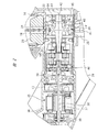
図1に示す打込機10はハウジング11を有する。ハウジング11は、シリンダケース12と、シリンダケース12に接続されたモータケース13と、シリンダケース12に接続されたハンドル14と、ハンドル14とモータケース13とを接続する装着部15と、を備えている。
The
シリンダ16がシリンダケース12内に固定して設けられ、ピストン17がシリンダ16内に収容されている。ピストン17はシリンダ16の中心線A1方向に移動可能である。ドライバブレード18がピストン17に固定されている。ピストン17及びドライバブレード18は打撃部19を構成する。
The
蓄圧容器20がシリンダケース12内に設けられ、蓄圧容器20はシリンダ16に固定されている。圧力室21が、蓄圧容器20の内部からシリンダ16の内部に亘って形成されている。シール部材がピストン17の外周面に取り付けられ、シール部材は、圧力室21を気密にシールする。気体が圧力室21に充填されている。気体は圧縮性の気体であればよく、気体は、空気の他、不活性ガス、例えば、窒素ガス、希ガスを用いることができる。本開示では、圧力室21に空気が充填されている例を説明する。
The
図2に示すように、ホルダ22がシリンダケース12内に設けられ、ホルダ22はバンパ23を支持している。バンパ23は、ゴム製またはウレタン製である。バンパ23は環状であり、かつ、軸孔24を有する。ドライバブレード18は軸孔24内で中心線A1方向に移動可能である。
As shown in FIG. 2, the
射出部25がシリンダケース12から中心線A1方向に突出しており、射出部25に射出路26が設けられている。射出部25は、図6Aに示すブレードガイド52を有し、ブレードガイド52により射出路26が形成されている。射出路26は、要素同士の隙間、要素に設けた溝の何れでもよい。ブレードガイド52は、ドライバブレード18の移動姿勢を保持する機能と、止具31の移動姿勢を保持する機能と、を有する。
The
図1及び図3のように、プッシュレバー27が射出部25に設けられ、プッシュレバー27は射出部25に対して中心線A1方向に移動可能である。プッシュレバー27は、弾性部材によりバンパ23から離れる向きに付勢されている。プッシュレバー27を付勢する弾性部材は、金属製のバネを含む。プッシュレバー27は、中心線A1方向の荷重を受けて変形しにくい材質、例えば、金属製または硬質樹脂製である。
As shown in FIGS. 1 and 3, a
作業者が打込機10を持ってプッシュレバー27を被打込材W1に押し付けると、プッシュレバー27はバンパ23に近づく向きで移動し、かつ、第1ストッパに接触して停止する。プッシュレバー27を被打込材W1対象物から離すと、プッシュレバー27は弾性部材の付勢力でバンパ23から離れる向きで移動し、プッシュレバー27は第2ストッパに接触して初期位置で停止する。
When the operator holds the driving
射出部25に、図11に示すプッシュレバースイッチ69が設けられている。プッシュレバースイッチ69は、プッシュレバー27が初期位置に停止しているとオフする。プッシュレバースイッチ69は、プッシュレバー27が被打込材W1に押し付けられて初期位置から移動するとオンする。
The
ドライバブレード18は、射出路26及びシリンダ16内で中心線A1方向に移動可能である。ドライバブレード18は軸形状であり、図4のように、ドライバブレード18の縁から突出した凸部28が複数設けられている。複数の凸部28は、ドライバブレード18の長手方向で互いに間隔をおいて配置されている。
The
図1のように、長尺状のマガジン29がハウジング11に取り付けられている。図2のように、マガジン29の長手方向を表す基準線A2に沿って供給路30が設けられている。複数の止具31が接続要素により互いに接続された状態で、供給路30に収容されている。止具31は軸形状の釘であるものとする。接続要素は、ワイヤ、接着剤の何れでもよい。
As shown in FIG. 1, a
マガジン29は、基準線A2に沿って設けたガイドレール32と、ガイドレール32に沿って移動可能なフィーダ33と、フィーダ33を付勢する弾性部材34と、を有する。弾性部材34は、フィーダ33を基準線A2と平行に、かつ、射出部25に近づく向きで付勢する。フィーダ33は、スライダ62と、スライダ62に取り付けた接触子63と、を有する。接触子63は、基準線A2方向で射出路26とスライダ62との間に配置されている。打込機10を図1のように側面視すると、中心線A1と基準線A2とが交差する。図1に示す打込機10は、中心線A1と基準線A2との間に形成される角度が90度ではない例である。
The
図5に示す弾性部材34は、金属製の渦巻きばねを用いた例である。渦巻きばねがスライダ62に取り付けられ、その渦巻きばねの端部がマガジン29に接続されている。接触子63は、供給路30に並べられた複数の止具31のうち、射出部25から最も離れた位置の止具31に押し付けられる。フィーダ33は、弾性部材34の付勢力で止具31を射出路26に送る。
The
図2のように、電動モータ35がモータケース13内に配置されている。電動モータ335は、モータケース13に固定されたステータ36と、モータケース13内に回転可能に配置したロータ37と、を有する。ステータ36は、鋼板と、鋼板に巻き付けた通電コイルと、を有する。ロータ37は、ロータコアと、ロータコアに取り付けた永久磁石と、を有する。ロータ37は回転軸38に固定されている。モータケース13内に軸受39が設けられ、軸受39は回転軸38を回転可能に支持する。電動モータ35は、例えば、3相交流形のブラシレスモータであり、通電コイルは、U相、V相、W相に対応する3種類の通電コイルを含む。モータケース13内に図11に示す回転状態検出センサ70が設けられている。回転状態検出センサ70は、ロータ37の回転数及び回転方向の位置を検出する。
As shown in FIG. 2, the
減速機40及び変換機構41がモータケース13内に設けられている。減速機40は、回転軸38の回転力を駆動軸42に伝達する機構である。減速機40は、複数の遊星歯車機構を有し、減速機40の入力要素は回転軸38に連結され、減速機40の出力要素は駆動軸42に連結されている。モータケース13内に軸受64が設けられ、軸受64は駆動軸42を回転可能に支持する。
The
減速機40の減速比は一定である。減速機40は、回転軸38の回転速度よりも駆動軸42の回転速度を低速として、回転力を伝達する。電動モータ35の回転力が減速機40を経由して駆動軸42に伝達される場合、駆動軸42の回転方向は正回転である。変換機構41は、回転力をドライバブレード18の移動力に変換する機構である。
The reduction ratio of the
図4のように、ホイール43は複数のピニオンピン44を有する。複数のピニオンピン44は、中心線A3を中心とする回転方向に沿って互いに間隔をおいて配置されている。複数のピニオンピン44は、ホイール43の回転に伴い、ドライバブレード18の凸部28のそれぞれに対して、別個に係合及び解放可能である。複数のピニオンピン44及び複数の凸部28は、ラック・アンド・ピニオン機構を構成する。変換機構41は、複数のピニオンピン44と複数の凸部28と、を含む。変換機構41は、複数のピニオンピン44と複数の凸部28と、を含む。
As shown in FIG. 4, the
モータケース13内には、図11に示す位置検出センサ71が設けられている。位置検出センサ71は、ホイール43の回転方向の位置を検出して信号を出力する。モータケース13内に回転規制機構45が設けられている。回転規制機構45は、減速機40から伝達される回転力で駆動軸42及びホイール43が回転することを許容する。回転規制機構45は、ドライバブレード18の力でホイール43に回転力が加わると、ホイール43及び駆動軸42が回転することを防止する。
The
図1に示すように、装着部15に取り付け及び取り外しが可能なバッテリ46が設けられている。バッテリ46は、収容ケースと、収容ケース内に収容した電池セルと、収容ケースに設けた端子と、を有する直流電源である。電池セルは、リチウムイオン電池、ニッケル水素電池、リチウムイオンポリマー電池及びニッケルカドミウム電池を含む。電池セルは、充電と放電とを繰り返すことの可能な二次電池である。
As shown in FIG. 1, a
トリガ47がハンドル14に設けられている。トリガ47は、ハンドルに対して移動可能に設けられたレバーである。作業者は、ハンドル14を手で握った状態でトリガ47のOn/Off動作が可能である。トリガ47のOnは、操作力を加えることであり、トリガ47のOffは、操作力を解除することである。ハンドル14の内部に、図11に示すトリガスイッチ68が設けられている。作業者がトリガ47に操作力を加えるとトリガスイッチ68はオンし、操作力を解除するとトリガスイッチ68はオフする。
A
制御部48が装着部15内に設けられている。制御部48は、図11に示すマイクロコンピュータ66及びインバータ回路67を有する。マイクロコンピュータ66は、入出力インタフェース、中央演算処理部及び記憶部を有する。インバータ回路67は、電動モータ35のステータ36に接続されており、複数のスイッチング素子を有する。複数のスイッチング素子は、それぞれオン・オフが切り替えられる。
The
制御部48は、トリガスイッチ68の信号、プッシュレバースイッチ69の信号、回転状態検出センサ70の信号、位置検出センサ71の信号を検出する。制御部48は、各種の信号を処理してインバータ回路67を制御し、電動モータ35の回転と停止とを切り替える。図1に示す変換機構41、制御部48、図2に示す電動モータ35により、移動機構65が構成されている。
The
次に、打込機10の使用例を説明する。制御部48は、トリガスイッチ68のオフ、またはプッシュレバースイッチ69のオフのうち、少なくとも一方を検出すると、インバータ回路67のスイッチング素子をオフする。このため、バッテリ46の電力は電動モータ35に供給されず、電動モータ35は停止している。圧力室21の圧力はピストン17に加わり、ピストン17及びドライバブレード18は中心線A1方向に付勢されている。ピニオンピン44と凸部28とが係合している。
Next, an example of using the driving
ドライバブレード18が受ける付勢力はホイール43に伝達され、ホイール43は図4で時計方向の回転力を受ける。回転規制機構45は、ドライバブレード18から加わる力でホイール43が回転することを防止し、ピストン17及びドライバブレード18は待機位置で停止している。ピストン17の待機位置は、ピストン17の上死点と下死点との間である。ピストン17の上死点は、中心線A1方向でバンパ23から最も離れた位置である。ピストン17の下死点は、中心線A1方向でバンパ23に接触した位置である。
The urging force received by the
ピストン17が待機位置で停止していると、図6Aのように、ドライバブレード18の先端49は、複数の止具31のうち射出路26に最も近い止具31の後端50と先端51との間に位置する。後端50は、被打込材W1に対する撃ち込み方向の後端であり、先端51は、被打込材W1に対する撃ち込み方向の先端である。フィーダ33は弾性部材34の力で複数の止具31を付勢しており、釘複数の止具31のうち射出路26に最も近い止具31は、ドライバブレード18に押し付けられている。
When the
制御部48は、トリガスイッチ68がオンされ、かつ、プッシュレバースイッチ69がオンされていることを検出すると、インバータ回路を制御してバッテリ46の電力を電動モータ35に供給する。電動モータ35の回転力は、減速機40を経由して駆動軸42に伝達される。駆動軸42及びホイール43は、図4で反時計回りに回転する。
When the
ホイール43の回転力は、ドライバブレード18に伝達され、ピストン17が図1において第2方向D2で移動する。ピストン17が図1において第2方向D2で移動することを上昇と呼ぶ。ピストン17が上昇すると、圧力室21の圧力が上昇する。
The rotational force of the
ピストン17が上死点に到達した後、図4のように、全てのピニオンピン44が凸部28から解放される。ピストン17は、圧力室21の圧力でバンパ23に近づく向きの第1方向で移動する。ピストン17が図1で第1方向D1で移動することを下降と呼ぶ。第2方向D2は第1方向D1に対して逆向きである。ドライバブレード18は、射出路26に送られる1本の止具31を打撃し、止具31が被打込材W1に打ち込まれる。
After the
また、ピストン17は、止具31が被打込材W1に打ち込まれた後、バンパ23に衝突する。バンパ23は中心線A1方向の圧縮荷重を受けて弾性変形し、バンパ23はピストン17及びドライバブレード18の運動エネルギを吸収する。また、制御部48は、ドライバブレード18が止具31を打撃した後も、電動モータ35を回転する。ピニオンピン44が凸部28に係合し、ピストン17が下死点から上死点に向けて移動する。制御部48は、ピストン17が待機位置に到達すると、電動モータ35を停止する。制御部48は、位置検出センサ71の信号を処理して、ピストン17が待機位置に到達したことを推定する。
Further, the
以後、上記の操作、動作、制御を行い、マガジン29に収容されている止具31を、順次、被打込材W1に打ち込むと、マガジン29に収容されている止具31の数が減少する。マガジン29に収容されている止具31の数を、止具31の残数と記載する。本開示の打込機10は、止具31の残数が、予め設定された所定数未満になると、その状態を作業者に知らせる残数告知機構B1を有する。
After that, when the above operations, operations, and controls are performed and the
残数告知機構B1を説明する。プッシュレバー27は、係合部53を有する。係合部53は、プッシュレバー27からマガジン29に向けて突出している。ストッパ54及び中間部材55がマガジン29に設けられている。ストッパ54及び中間部材55は、マガジン29に対して基準線A2方向に所定の範囲内で移動可能である。また、中間部材55はストッパ54に対して、基準線A2に方向に移動可能である。ストッパ54及び中間部材55は、基準線A2方向の荷重で塑性変形しにくい材質、例えば、金属製、硬質樹脂製である。
The remaining number notification mechanism B1 will be described. The
中間部材55を基準線A2方向に付勢する弾性部材56が設けれている。弾性部材56は、中間部材55を射出路26から離れる向きで付勢する。図6A及び図12は、弾性部材56を中間部材55とマガジン29に設けた受け部72との間に配置した例を示す。弾性部材56は金属製の圧縮ばねを用いることができる。マガジン29に規制部57が設けられ、ストッパ54は規制部57により移動範囲が規制される。規制部57は、ストッパ54が接触及び離間可能な壁または突起の何れでもよい。規制部57はストッパとしての機能を有する。
An
また、ストッパ54と中間部材55との間に弾性部材58が設けられけている。弾性部材58は金属製の圧縮ばねである。弾性部材58の第1端部はストッパ54に押し付けられ、弾性部材58の第2端部は中間部材55に押し付けられている。図7Aのように、ストッパ54に係合部59が設けられ、中間部材55に係合部60が設けられている。ストッパ54は弾性部材58に付勢され、係合部59は係合部60に押し付けられる。つまり、弾性部材56の付勢力は、中間部材55を介して間接にストッパ54に伝達される。
Further, an
残数告知機構B1は、ストッパ54、中間部材55、弾性部材34,56,58、係合部53等により構成されている。弾性部材34のばね定数は、弾性部材56,58のそれぞれのばね定数よりも大きい。
The remaining number notification mechanism B1 is composed of a
本開示の打込機10は止具31の残数が、予め設定された所定数以上であると、図7Aのように、フィーダ33は中間部材55から離れている。中間部材55は、弾性部材56により射出路26から離れる向きに付勢され、ストッパ54は規制部57に押し付けられて停止している。ストッパ54が規制部57に押し付けられていると、ストッパ54の係合部61は、係合部53の移動範囲外に位置する。このため、プッシュレバー27が被打込材W1に押し付けられると、ストッパ54はプッシュレバー27の移動を阻害せず、プッシュレバースイッチ69がオンする。
In the driving
これに対して、止具31の残数が減少することに伴い、フィーダ33は弾性部材34の付勢力で射出路26に近づく。そして、プッシュレバー27が被打込材W1から離れている状態で、止具31の残数が予め設定された所定数未満になると、フィーダ33が中間部材55に押し付けられる。
On the other hand, as the remaining number of the
すると、中間部材55は、弾性部材56の付勢力に抗して射出路26に近づく。中間部材55の移動力は、弾性部材58を介してストッパ54に伝達される。そして、図7Bのように、ストッパ54の係合部61が係合部53の移動範囲内に進入する。この状態で、作業者がプッシュレバー27を被打込材W1に押し付けると、図6Bのように、係合部61が係合部53と係合し、ストッパ54はプッシュレバー27の移動を阻害する。
Then, the
したがって、プッシュレバー27の移動が阻害され、プッシュレバースイッチ69はオフに維持される。つまり、電動モータ35は停止した状態に維持され、止具31は打ち込まれない。このため、作業者は止具31の残数が、予め設定された所定数未満になったことを認識できる。
Therefore, the movement of the
次に、プッシュレバー27が被打込材W1に押し付けられている状態で、止具31の残数が、予め設定された所定数未満になる場合の動作及び制御を説明する。例えば、作業者が、プッシュレバー27を被打込材W1に押し付けた状態を維持し、かつ、トリガスイッチ68のオンとオフとが交互に繰り返されると、止具31が順次、被打込材W1に打ち込まれ、止具31残数が減少する。止具31の残数が所定数以上であると、図8Aのように、フィーダ33は中間部材55から離れている。また、弾性部材56の付勢力が中間部材55を介してストッパ54に伝達され、ストッパ54は規制部57に押し付けられて停止している。さらに、ストッパ54の係合部61は係合部53から離れている。
Next, the operation and control when the remaining number of the
止具31の打ち込みが繰り返されて、止具31の残数が所定値未満になると、図8B及び図9Aのように、フィーダ33が中間部材55に押し付けられ、中間部材55は弾性部材56の付勢力に抗して射出路26に近づく。中間部材55の移動力は、弾性部材58を介してストッパ54に伝達され、ストッパ54は射出路26に近づく。このためストッパ54の係合部61は係合部53に押し付けられ、ストッパ54は停止する。
When the number of the
プッシュレバースイッチ69がオンされている状態で、トリガスイッチ68がオフからオンに切り替わり、電動モータ35が回転すると、ドライバブレード18が図9Bのように上昇する。
When the
ドライバブレード18が上昇すると、図10Aのように、フィーダ33が弾性部材34の付勢力で射出路26に近づき、止具31の送り方向で先頭に位置する止具31は、射出路26に送られる。さらに、ドライバブレード18が下降して射出路26の止具31を打撃し、止具31は図10Bのように被打込材W1に打ち込まれる。
When the
以後、プッシュレバー27が被打込材W1に押し付けられた状態で、トリガスイッチ68のオンとオフとが繰り返されると、ストッパ54が停止している状態で、フィーダ33は射出路26に近づき、かつ、ドライバブレード18が上昇及び下降を繰り返し、マガジン29から射出路26に送られる止具31を、順次、被打込材W1に打ち込む。
After that, when the
本開示の打込機10は、次の第1機能及び第2機能を、共に得ることができる。
The driving
第1機能は、止具31の残数が所定数未満になり、かつ、プッシュレバー27が被打込材W1から離れると、ストッパ54の係合部61が、図6A,図7Bのように、係合部53の移動領域に位置することである。このため、プッシュレバー27が被打込材W1に押し付けられても、図6Bのように係合部61が係合部53に係合し、プッシュレバー27は移動せず、かつ、プッシュレバースイッチ69はオフに維持される。したがって、電動モータ35が停止状態に維持されて止具31は打ち込まれない。止具31の残数がゼロを含む所定数であるときに、打込み動作を抑制するために空打ちを防止できる。そして作業者は止具31の補充が必要であることを認識できる。
The first function is that when the remaining number of the
第2機能は、プッシュレバー27が被打込材W1に押し付けられた状態で、止具31の打ち込みが行われて、止具31の残数が、補充の必要な所定数になった場合に、マガジン29内の止具31を射出路26に送ることである。したがって、マガジン29に収容されている止具31を射出路26に送る動作を、円滑に行うことが可能である。また、射出路26に送られた止具31を、ドライバブレード18で打撃できる。
The second function is when the
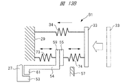
図5及び図6Aに示す残数告知機構B1の他の例が、図13Aに示されている。ストッパ54を射出路26から離れる向きで付勢する弾性部材73が設けられている。図13Aは、ストッパ54の係合部59とマガジン29との間に弾性部材73を配置した例を示す。弾性部材73は金属製の圧縮ばねである。弾性部材73は、ストッパ54を直接付勢する。中間部材55とフィーダ33との間に弾性部材74が設けられている。弾性部材74は金属製の圧縮ばねが好適である。弾性部材74は、中間部材55を射出路26に近づく向きで付勢する。弾性部材74は中間部材55と一体であってもよく、弾性力を有する構造であれば、樹脂等の他の弾性材料であってもよい。
Another example of the remaining number notification mechanism B1 shown in FIGS. 5 and 6A is shown in FIG. 13A. An
打込機10は止具31の残数が、予め設定された所定数以上であると、図13Aのように、中間部材55は係合部59から離れている。ストッパ54は規制部57に押し付けられて停止している。ストッパ54が規制部57に押し付けられていると、ストッパ54の係合部61は、係合部53の移動範囲外に位置する。このため、図1に示すプッシュレバー27が被打込材W1に押し付けられると、ストッパ54はプッシュレバー27の移動を阻害せず、図11に示すプッシュレバースイッチ69がオンする。
When the remaining number of the
これに対して、止具31の残数が減少することに伴い、フィーダ33は弾性部材34の付勢力で射出路26に近づく。そして、図1に示すプッシュレバー27が被打込材W1から離れている状態で、止具31の残数が予め設定された所定数未満になると、中間部材55が係合部59に押し付けられる。
On the other hand, as the remaining number of the
すると、ストッパ54は、弾性部材73の付勢力に抗して射出路26に近づく。そして、図13Bのように、ストッパ54の係合部61が係合部53の移動範囲内に進入する。この状態で、作業者がプッシュレバー27を被打込材W1に押し付けると、係合部61が係合部53と係合し、ストッパ54はプッシュレバー27の移動を阻害する。
Then, the
したがって、プッシュレバー27の移動が阻害され、プッシュレバースイッチ69はオフに維持される。つまり、電動モータ35は停止した状態に維持され、止具31は打ち込まれない。このため、作業者は、止具31の残数が、予め設定された所定数未満になったことを認識できる。
Therefore, the movement of the
次に、図1に示すプッシュレバー27が被打込材W1に押し付けられている状態で、止具31の残数が、予め設定された所定数未満になる場合において、図13Aに示す残数告知機構B1の作動を説明する。止具31の残数が所定数以上であると、図14Aのように、中間部材55は係合部59から離れている。また、ストッパ54は、弾性部材74の付勢力で規制部57に押し付けられて停止している。さらに、ストッパ54の係合部61は係合部53から離れている。
Next, when the
止具31の打ち込みが繰り返されて、止具31の残数が所定値未満になると、中間部材55は係合部59に押し付けられ、ストッパ54は弾性部材73の付勢力に抗して射出路26に近づく。このため、図14Bのように、ストッパ54の係合部61は係合部53に押し付けられ、ストッパ54は停止する。
When the number of the
図11に示すプッシュレバースイッチ69がオンされている状態で、トリガスイッチ68がオフからオンに切り替わり、電動モータ35が回転すると、ドライバブレード18が上昇する。ドライバブレード18が上昇すると、フィーダ33が弾性部材34の付勢力で射出路26に近づき、止具31の送り方向で先頭に位置する止具31は、射出路26に送られる。そして、ドライバブレード18が下降して射出路26の止具31を打撃し、止具31は被打込材W1に打ち込まれる。図13Aに示す残数告知機構B1を備えた打込機10においても、前述した第1機能及び第2機能を、共に得ることができる。
When the
本開示の要素の意味は、次の通りである。止具31は止具であり、プッシュレバー27は押し付け部材であり、弾性部材34は付勢部材である。中間部材55及び弾性部材58は、移動力伝達部材である。ドライバブレード18の先端49は、打撃部の先端である。回転規制機構45は保持機構である。トリガ47は操作部材であり、ホイール43は回転要素である。また、弾性部材56,73は押圧部材である。弾性部材34は第1付勢部材として把握でき、弾性部材56,73は第2付勢部材として把握できる。
The meanings of the elements of this disclosure are as follows. The
打込機は、開示した実施形態に限定されるものではなく、その要旨を逸脱しない範囲で種々変更可能である。例えば、気体の圧力で打撃部を移動させる移動機構は、外部から圧縮空気を供給する方式の空気工具であってもよい。また、密閉空間に気体を充填した空気バネ方式においては、伸縮可能なベローズと、ベローズ内に形成した圧力室と、を備えていてもよい。ベローズは、中心線方向に伸縮可能であり、ベローズの伸縮方向の端部に打撃部が取り付けられる。また、移動機構は、気体の圧力で打撃部を移動させる機構の他、弾性部材の弾性力で打撃部を移動させる機構を含む。ここで、弾性部材は金属製の圧縮ばねを含む。さらに、高速で回転運動等を行う打ち出し構造体と、打撃部とを接触させることによって、打撃部及び止具を移動させる構成であってもよい。 The driving machine is not limited to the disclosed embodiment, and can be variously changed without departing from the gist thereof. For example, the moving mechanism that moves the striking portion by the pressure of gas may be an air tool of a type that supplies compressed air from the outside. Further, in the air spring system in which the closed space is filled with gas, a stretchable bellows and a pressure chamber formed in the bellows may be provided. The bellows can be expanded and contracted in the center line direction, and a striking portion is attached to the end of the bellows in the expansion and contraction direction. Further, the moving mechanism includes a mechanism for moving the striking portion by the pressure of gas and a mechanism for moving the striking portion by the elastic force of the elastic member. Here, the elastic member includes a metal compression spring. Further, the striking portion and the stopper may be moved by bringing the striking portion into contact with the launching structure that performs rotational movement at high speed.
打撃部を移動させる移動機構は、ラック・アンド・ピニオン機構の他、カム機構またはウィンチ機構を用いることも可能である。カム機構は、モータの回転力で回転するカム板と、カム板のカム面に接触する接触子と、を有する。ウィンチ機構は、モータの回転力が伝達される回転要素と、回転要素と打撃部とを接続するケーブルと、を有する。回転要素は、ギヤ、スプロケット、プーリ、シャフト、を含む。 As the moving mechanism for moving the striking portion, a cam mechanism or a winch mechanism can be used in addition to the rack and pinion mechanism. The cam mechanism has a cam plate that is rotated by the rotational force of the motor and a contact that comes into contact with the cam surface of the cam plate. The winch mechanism has a rotating element to which the rotational force of the motor is transmitted, and a cable connecting the rotating element and the striking portion. Rotating elements include gears, sprockets, pulleys, shafts.
制御部は、マイクロコンピュータの他、プロセッサ、ユニット、モジュールを含む。制御部は、電気部品または電子部品単体で構成されているもの、複数の電気部品または複数の電子部品で構成されているものを含む。制御部は、信号、情報、データを処理する。 The control unit includes a processor, a unit, and a module in addition to the microcomputer. The control unit includes one composed of an electric component or an electronic component alone, and one composed of a plurality of electric components or a plurality of electronic components. The control unit processes signals, information, and data.
マガジンが保持する止具の所定数は、“1“以上であればよい。フィーダ、中間部材、ストッパ等の要素を付勢する弾性部材は、要素を付勢する方向に合わせて、ばね、合成ゴムを用いることができる。ばねは、要素を付勢する方向、及びばねの配置位置に応じて、圧縮ばね、引張りばねを用いることが可能である。ばねの形状や構造は、コイルばね、渦巻きばね、ねじりばね、板ばねの何れでもよい。これらのばねの材質は、金属製、合成樹脂製を用いることができる。 The predetermined number of fasteners held by the magazine may be "1" or more. As the elastic member that urges the element such as the feeder, the intermediate member, and the stopper, a spring or synthetic rubber can be used according to the direction in which the element is urged. As the spring, a compression spring or a tension spring can be used depending on the direction in which the element is urged and the position of the spring. The shape and structure of the spring may be any of a coil spring, a spiral spring, a torsion spring, and a leaf spring. As the material of these springs, metal or synthetic resin can be used.
図7Aに示す弾性部材56は、射出部25と係合部60との間に配置することも可能である。つまり、弾性部材56の配置位置は、中間部材55を射出部25から離れる向きに付勢する位置であればよい。
The
図13Aに示す弾性部材73は、射出部25と係合部60との間に配置することも可能である。つまり、弾性部材73の配置位置は、ストッパ54を射出部25から離れる向きに付勢する位置であればよい。
The
モータは、電動モータ、油圧モータ、空気圧モータの何れでもよい。電動モータの電源は、直流電源または交流電源の何れでもよい。打込機の実施形態は、図1に示す中心線A1と基準線A2との間に形成される角度が90度となるように、シリンダ16とマガジン29との位置関係が設計されているものを含む。
The motor may be an electric motor, a hydraulic motor, or a pneumatic motor. The power source of the electric motor may be either a DC power source or an AC power source. In the embodiment of the driving machine, the positional relationship between the
操作部材は、作業者の指により操作される要素であり、操作部材は、ハウジングに対して移動可能に設けられるボタン、レバー、スイッチを含む。また、操作部材は、ハウジングに対して移動不可能に設けられ、かつ、作業者が指で押す操作力の付与及び解除を検出可能な圧電素子、操作パネルを含む。中間部材は、フィーダの移動力をストッパに伝達する要素であり、中間部材は、アーム、ロッド、プランジャ、レバー、リンクの何れでもよい。止具は、軸形状の釘、コ字形の金属片の何れでもよい。また、止具は、釘頭部に平面部を有するT字状釘に限らず、平面釘を有しないI字状のピン釘であってもよい。 The operating member is an element operated by an operator's finger, and the operating member includes buttons, levers, and switches that are movably provided with respect to the housing. Further, the operation member includes a piezoelectric element and an operation panel which are provided so as not to be movable with respect to the housing and can detect the application and release of the operation force pressed by the operator with a finger. The intermediate member is an element that transmits the moving force of the feeder to the stopper, and the intermediate member may be any of an arm, a rod, a plunger, a lever, and a link. The stopper may be either a shaft-shaped nail or a U-shaped metal piece. Further, the stopper is not limited to a T-shaped nail having a flat surface portion on the nail head, and may be an I-shaped pin nail having no flat surface nail.
10…打込機、11…ハウジング、18…ドライバブレード、19…打撃部、21…圧力室、25…射出部、27…プッシュレバー、29…マガジン、31…止具、33…フィーダ、34,58…弾性部材、35…電動モータ、41…変換機構、43…ホイール、45…回転規制機構、47…トリガ、49,51…先端、50…後端、54…ストッパ、55…中間部材、65…移動機構、D1…第1方向、D2…第2方向。 10 ... driving machine, 11 ... housing, 18 ... driver blade, 19 ... striking part, 21 ... pressure chamber, 25 ... injection part, 27 ... push lever, 29 ... magazine, 31 ... stopper, 33 ... feeder, 34, 58 ... Elastic member, 35 ... Electric motor, 41 ... Conversion mechanism, 43 ... Wheel, 45 ... Rotation regulation mechanism, 47 ... Trigger, 49, 51 ... Tip, 50 ... Rear end, 54 ... Stopper, 55 ... Intermediate member, 65 ... movement mechanism, D1 ... first direction, D2 ... second direction.
Claims (6)
前記射出部に設けられ、かつ、前記被打込材に押し付けられると前記射出部に対して移動する押し付け部材と、
前記マガジンに設けられ、かつ、前記射出部に近づく向きで移動して前記止具を前記射出部に送るフィーダと、
前記マガジンに対して前記射出部に近づく向きで移動可能に設けられ、かつ、前記押し付け部材に係合及び解放が可能なストッパと、
前記フィーダを前記射出部に近づける向きで付勢する付勢部材と、
前記フィーダの移動力を前記ストッパに伝達する移動力伝達部材と、
を有し、
前記ストッパは、前記マガジンが保持する前記止具の数が所定数以上であると、前記押し付け部材から解放されて前記押し付け部材の移動を許容し、
前記ストッパは、前記マガジンが保持する前記止具の数が所定数未満であると、前記押し付け部材に係合して前記押し付け部材の移動を防止し、
前記フィーダは、前記押し付け部材が前記被打込材に押し付けられ、かつ、前記ストッパが前記押し付け部材に接触して前記ストッパの移動が阻害されている場合に、前記止具を前記射出部に送り、
前記移動力伝達部材は、前記マガジンが保持する前記止具の数が所定数以上であると前記フィーダの移動力を前記ストッパに伝達せず、
前記移動力伝達部材は、前記マガジンが保持する前記止具の数が所定数未満であると前記フィーダの移動力を前記ストッパに伝達する、打込機。 A driving portion including a magazine for holding the stopper, an injection portion to which the stopper is sent from the magazine, and a striking portion for striking the stopper sent to the injection portion to strike the material to be driven. It ’s a machine,
A pressing member provided on the injection portion and moving with respect to the injection portion when pressed against the material to be driven.
A feeder provided in the magazine and moving in a direction approaching the injection portion to send the stopper to the injection portion.
A stopper that is movably provided with respect to the magazine in a direction approaching the injection portion and that can be engaged and disengaged from the pressing member.
An urging member that urges the feeder in a direction that brings it closer to the injection portion,
A moving force transmitting member that transmits the moving force of the feeder to the stopper,
Have,
When the number of the stoppers held by the magazine is equal to or greater than a predetermined number, the stopper is released from the pressing member to allow the pressing member to move.
When the number of the stoppers held by the magazine is less than a predetermined number, the stopper engages with the pressing member to prevent the pressing member from moving.
The feeder sends the stopper to the injection portion when the pressing member is pressed against the driven material and the stopper comes into contact with the pressing member to hinder the movement of the stopper. ,
The moving force transmitting member does not transmit the moving force of the feeder to the stopper when the number of the stoppers held by the magazine is a predetermined number or more.
The moving force transmission member, the number of the fastener in which the magazine is held by you transmit moving force of the feeder is less than the predetermined number in the stopper, driving machine.
前記押し付け部材が前記被打込材に押し付けられて移動すると、前記打撃部を前記第1方向とは逆の第2方向に移動させて前記圧力室の圧力を上昇させる移動機構と、
前記打撃部を前記第2方向に移動させる前に前記圧力室の圧力に抗して停止させ、かつ、前記打撃部の先端を前記止具の先端と後端との間に位置させる保持機構と、
が設けられている、請求項1記載の打込機。 A pressure chamber in which the striking portion is moved in the first direction by the pressure of gas and the striking portion strikes the stopper.
When the pressing member is pressed against the material to be driven and moves, the striking portion is moved in a second direction opposite to the first direction to increase the pressure in the pressure chamber.
A holding mechanism that stops the striking portion against the pressure of the pressure chamber before moving the striking portion in the second direction and positions the tip of the striking portion between the tip and the rear end of the stopper. ,
Is provided, the driving machine of claim 1, wherein.
前記ハウジングに取り付けられて作業者が操作する操作部材と、
が設けられ、
前記移動機構は、
モータと、
前記モータの回転力で回転する回転要素と、
前記回転要素の回転力を前記打撃部の前記第2方向の移動力に変換する変換機構と、
前記操作部材が操作され、かつ、前記押し付け部材が前記射出部に対して移動すると、前記モータを回転させる制御部と、
を有する、請求項2記載の打込機。 A housing that movably supports the striking portion and
An operating member attached to the housing and operated by an operator,
Is provided,
The moving mechanism
With the motor
A rotating element that rotates with the rotational force of the motor,
A conversion mechanism that converts the rotational force of the rotating element into the moving force of the striking portion in the second direction, and
A control unit that rotates the motor when the operating member is operated and the pressing member moves with respect to the injection unit.
2. The driving machine according to claim 2 .
前記押圧部材は、前記マガジンが保持する前記止具の数が所定数以上であると、前記ストッパを前記押し付け部材から解放させ、
前記押圧部材は、前記マガジンが保持する前記止具の数が所定数未満であると、前記ストッパを前記押し付け部材に係合させる、請求項1乃至3の何れか1項記載の打込機。 A pressing member for urging the stopper in a direction away from the injection portion is provided.
When the number of the stoppers held by the magazine is equal to or greater than a predetermined number, the pressing member releases the stopper from the pressing member.
The driving machine according to any one of claims 1 to 3 , wherein the pressing member engages the stopper with the pressing member when the number of the stoppers held by the magazine is less than a predetermined number.
Priority Applications (1)
| Application Number | Priority Date | Filing Date | Title |
|---|---|---|---|
| JP2016177407A JP6790629B2 (en) | 2016-09-12 | 2016-09-12 | Driving machine |
Applications Claiming Priority (1)
| Application Number | Priority Date | Filing Date | Title |
|---|---|---|---|
| JP2016177407A JP6790629B2 (en) | 2016-09-12 | 2016-09-12 | Driving machine |
Publications (2)
| Publication Number | Publication Date |
|---|---|
| JP2018043294A JP2018043294A (en) | 2018-03-22 |
| JP6790629B2 true JP6790629B2 (en) | 2020-11-25 |
Family
ID=61692353
Family Applications (1)
| Application Number | Title | Priority Date | Filing Date |
|---|---|---|---|
| JP2016177407A Active JP6790629B2 (en) | 2016-09-12 | 2016-09-12 | Driving machine |
Country Status (1)
| Country | Link |
|---|---|
| JP (1) | JP6790629B2 (en) |
Families Citing this family (1)
| Publication number | Priority date | Publication date | Assignee | Title |
|---|---|---|---|---|
| JP7115544B2 (en) * | 2018-07-06 | 2022-08-09 | 工機ホールディングス株式会社 | hammer |
Family Cites Families (8)
| Publication number | Priority date | Publication date | Assignee | Title |
|---|---|---|---|---|
| JPS573726Y2 (en) * | 1976-01-13 | 1982-01-23 | ||
| JPH0228007B2 (en) * | 1985-01-21 | 1990-06-21 | Hitachi Ltd | RAININGUSHAFUTO |
| JPH0228007Y2 (en) * | 1985-05-16 | 1990-07-27 | ||
| JPH08216055A (en) * | 1995-02-15 | 1996-08-27 | Max Co Ltd | No-load driving preventing mechanism of fastener driver |
| JP3558884B2 (en) * | 1998-08-10 | 2004-08-25 | 株式会社マキタ | Nailing machine |
| JP4761257B2 (en) * | 2006-09-12 | 2011-08-31 | 日立工機株式会社 | Fastener driving machine |
| JP5395333B2 (en) * | 2007-05-11 | 2014-01-22 | 日立工機株式会社 | Driving machine |
| JP5234427B2 (en) * | 2009-03-23 | 2013-07-10 | 日立工機株式会社 | Fastener driving machine |
-
2016
- 2016-09-12 JP JP2016177407A patent/JP6790629B2/en active Active
Also Published As
| Publication number | Publication date |
|---|---|
| JP2018043294A (en) | 2018-03-22 |
Similar Documents
| Publication | Publication Date | Title |
|---|---|---|
| JP7081595B2 (en) | Driving machine | |
| US11926027B2 (en) | Driving tool with rotating member to move striking unit | |
| CN110573304B (en) | Drive-in machine, striking mechanism and moving mechanism | |
| EP2716409B1 (en) | Activation system having multi-angled arm and stall release mechanism | |
| JP6790598B2 (en) | Driving machine | |
| JPWO2018100943A1 (en) | Driving machine | |
| EP4116039A1 (en) | Driving machine | |
| US11491625B2 (en) | Driving machine | |
| US20220134524A1 (en) | Driving tool | |
| JP6790629B2 (en) | Driving machine | |
| US20230025226A1 (en) | Driving device | |
| JPWO2020008768A1 (en) | Driving machine | |
| JP2018039064A (en) | Driving machine | |
| JP6766727B2 (en) | Driving machine | |
| JP6972981B2 (en) | Driving machine | |
| JP7359219B2 (en) | driving machine | |
| JP6673524B2 (en) | Driving machine | |
| JP2019098456A (en) | Driving-in machine | |
| JP6753341B2 (en) | Driving machine | |
| JP2020114610A (en) | Driving machine | |
| JP7413856B2 (en) | work equipment | |
| JP2021098256A (en) | Driving machine | |
| CN111936272A (en) | Driving machine | |
| JP2017213634A (en) | Placing machine |
Legal Events
| Date | Code | Title | Description |
|---|---|---|---|
| A621 | Written request for application examination |
Free format text: JAPANESE INTERMEDIATE CODE: A621 Effective date: 20190329 |
|
| A131 | Notification of reasons for refusal |
Free format text: JAPANESE INTERMEDIATE CODE: A131 Effective date: 20200630 |
|
| A521 | Written amendment |
Free format text: JAPANESE INTERMEDIATE CODE: A523 Effective date: 20200827 |
|
| TRDD | Decision of grant or rejection written | ||
| A01 | Written decision to grant a patent or to grant a registration (utility model) |
Free format text: JAPANESE INTERMEDIATE CODE: A01 Effective date: 20201006 |
|
| A61 | First payment of annual fees (during grant procedure) |
Free format text: JAPANESE INTERMEDIATE CODE: A61 Effective date: 20201019 |
|
| R150 | Certificate of patent or registration of utility model |
Ref document number: 6790629 Country of ref document: JP Free format text: JAPANESE INTERMEDIATE CODE: R150 |