JP6789716B2 - Image processing device, control method of image processing device, and program - Google Patents
Image processing device, control method of image processing device, and program Download PDFInfo
- Publication number
- JP6789716B2 JP6789716B2 JP2016154834A JP2016154834A JP6789716B2 JP 6789716 B2 JP6789716 B2 JP 6789716B2 JP 2016154834 A JP2016154834 A JP 2016154834A JP 2016154834 A JP2016154834 A JP 2016154834A JP 6789716 B2 JP6789716 B2 JP 6789716B2
- Authority
- JP
- Japan
- Prior art keywords
- bitmap
- memory
- intermediate data
- creating
- data
- Prior art date
- Legal status (The legal status is an assumption and is not a legal conclusion. Google has not performed a legal analysis and makes no representation as to the accuracy of the status listed.)
- Active
Links
Images


Classifications
-
- G—PHYSICS
- G06—COMPUTING; CALCULATING OR COUNTING
- G06K—GRAPHICAL DATA READING; PRESENTATION OF DATA; RECORD CARRIERS; HANDLING RECORD CARRIERS
- G06K15/00—Arrangements for producing a permanent visual presentation of the output data, e.g. computer output printers
- G06K15/02—Arrangements for producing a permanent visual presentation of the output data, e.g. computer output printers using printers
- G06K15/18—Conditioning data for presenting it to the physical printing elements
- G06K15/1835—Transforming generic data
- G06K15/1836—Rasterization
- G06K15/184—Rasterization from compressed bitmap data
-
- G—PHYSICS
- G06—COMPUTING; CALCULATING OR COUNTING
- G06K—GRAPHICAL DATA READING; PRESENTATION OF DATA; RECORD CARRIERS; HANDLING RECORD CARRIERS
- G06K15/00—Arrangements for producing a permanent visual presentation of the output data, e.g. computer output printers
- G06K15/02—Arrangements for producing a permanent visual presentation of the output data, e.g. computer output printers using printers
- G06K15/18—Conditioning data for presenting it to the physical printing elements
- G06K15/1867—Post-processing of the composed and rasterized print image
- G06K15/1886—Storage of the print image data or of parts thereof
Description
本発明は、画像処理装置、画像処理装置の制御方法、及びプログラムに関するものである。 The present invention relates to an image processing apparatus, a control method of the image processing apparatus, and a program.
従来、画像データを処理する画像処理装置において、画像描画処理時、画像データをブロックごとの画像データに変換し、以降の画像処理をブロック単位で並列に行うことで、高速に印刷を行う技術がある。画像データをブロックごとの画像データに変換する処理をブロック順変換処理と呼ぶ。
ブロック順変換処理は、ページライン順に所定のブロック高さ分のデータをワークメモリに入力し、ブロック順に出力する処理である。
特許文献1では、ワークメモリに入力されたラスタライズ前のベクタ形式のデータをブロック分割する方法と、ワークメモリに入りきらない場合にラスタライズ後の画像データをバッファしてブロック分割する方法に切り替える技術を開示している。
図15の(A)にベクタ形式のブロック順変換900と図15の(B)にラスタ形式のブロック順変換910の一例を示す。図15の(A)のベクタ形式のブロック順変換900は、ベクタデータをブロック901,902毎に分割するため、通常のデータではワークメモリは小さい。しかし、データによっては多くのワークメモリを必要とするため、図15の(B)に示すラスタ形式のブロック順変換910に切り替え、バンドメモリ912を確保し、ラスタ化した画像データを分割してブロック毎に出力する。
Conventionally, in an image processing device that processes image data, there is a technique for high-speed printing by converting image data into image data for each block during image drawing processing and performing subsequent image processing in parallel in block units. is there. The process of converting image data into image data for each block is called a block order conversion process.
The block order conversion process is a process of inputting data for a predetermined block height in the page line order into the work memory and outputting the data in the block order.
FIG. 15 (A) shows an example of the vector format block order conversion 900, and FIG. 15 (B) shows an example of the raster format block order conversion 910. In the block order conversion 900 in the vector format shown in FIG. 15A, the vector data is divided into
しかしながら、特許文献1のブロック順変換処理を用いた場合、画像データをバッファするメモリを取得する必要がある。このとき、中間データ生成用のメモリや画像データをスプールするためのメモリが空いていない場合は、メモリが解放されるまで待つ必要があり、処理終了までの時間がかかってしまうことになる。
図16に示す印刷処理フロー1000を用いて具体的に説明する。画像データスプール1011内は既に展開処理1002で展開済みの複数ページの画像データで空きメモリが少ない状態である。そして、中間データスプール(1010)内にも中間データ生成1001で生成済みの複数ページの中間データで空きメモリが少ない状態である。この状態で展開処理1002においてビットマップメモリが必要になっても空きメモリが足りずメモリを取得できないため、メモリが足りず、印刷処理が終了するまで展開処理1002は待つことになる。
However, when the block order conversion process of
A specific description will be given using the print processing flow 1000 shown in FIG. The image data spool 1011 is in a state where the free memory is small with the image data of multiple pages already expanded by the
本発明は、上記の課題を解決するためになされたもので、本発明の目的は、中間データ生成時に、第1のビットマップイメージ作成処理を第2のビットマップイメージ作成処理に切り替える場合でも、必要なビットマップメモリを遅延なくワークメモリから取得できる。 The present invention has been made to solve the above problems, and an object of the present invention is to switch the first bitmap image creation process to the second bitmap image creation process at the time of intermediate data generation. The required bitmap memory can be obtained from the work memory without delay.
上記目的を達成する本発明の画像処理装置は以下に示す構成を備える。
印刷データから生成される中間データを中間データメモリに格納して処理する画像処理装置であって、ページ単位の中間データから生成される1バンド分の閉領域データを生成する生成手段と、前記生成手段が生成した1バンド分の閉領域データを前記中間データメモリに確保されるワークメモリに格納し、該格納された1バンド分の閉領域データからブロック単位のビットマップイメージを作成する第1の作成手段と、ページ単位の中間データから生成される1バンド分の閉領域データから1バンド分のビットマップイメージを前記中間データメモリに確保されるワークメモリに展開し、該ワークメモリに展開した1バンド分のビットマップイメージからブロック単位のビットマップイメージを作成する第2の作成手段と、前記中間データメモリから確保するワークメモリのサイズがブロック変換に使用するブロックサイズを超えているかどうかを判断する判断手段と、前記判断手段が前記ワークメモリのサイズが前記ブロックサイズを超えていると判断した場合、前記第1の作成手段がビットマップを作成する処理を前記第2の作成手段によるビットマップを作成する処理に切り替える制御手段と、前記第1の作成手段がビットマップを作成する処理を開始する場合、前記ワークメモリに前記第2の作成手段で使用するビットマップメモリをあらかじめ確保するメモリ管理手段と、を備えることを特徴とする。
The image processing apparatus of the present invention that achieves the above object has the following configuration.
An image processing device that stores and processes intermediate data generated from print data in an intermediate data memory, and is a generation means for generating closed area data for one band generated from intermediate data for each page, and the generation. First, the closed area data for one band generated by the means is stored in the work memory secured in the intermediate data memory, and the bitmap image for each block is created from the stored closed area data for one band. The creation means and the bitmap image for one band from the closed area data for one band generated from the intermediate data for each page are expanded into the work memory secured in the intermediate data memory, and expanded in the work memory. It is determined whether or not the size of the work memory secured from the intermediate data memory exceeds the block size used for the block conversion and the second creation means for creating the bitmap image for each block from the bitmap images for the bands. When the determination means and the determination means determine that the size of the work memory exceeds the block size, the process of creating the bitmap by the first creation means is performed by the second creation means. A control means for switching to the process of creating, and a memory management means for allocating in advance the bitmap memory used in the second creation means in the work memory when the first creation means starts the process of creating a bitmap. It is characterized by having.
本発明によれば、中間データ生成時に、第1のビットマップイメージ作成処理を第2のビットマップイメージ作成処理に切り替える場合でも、必要なビットマップメモリを遅延なくワークメモリから取得できる。 According to the present invention, even when the first bitmap image creation process is switched to the second bitmap image creation process at the time of intermediate data generation, the necessary bitmap memory can be acquired from the work memory without delay.
次に本発明を実施するための最良の形態について図面を参照して説明する。
<システム構成の説明>
〔第1実施形態〕
Next, the best mode for carrying out the present invention will be described with reference to the drawings.
<Explanation of system configuration>
[First Embodiment]
<システム構成>
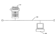
図1は、本発明の実施形態を示す画像処理装置を含むデータ処理システムの構成を示す図である。本システムでは、画像形成装置101、画像処理装置102がネットワーク103で接続する構成とする。
<System configuration>
FIG. 1 is a diagram showing a configuration of a data processing system including an image processing apparatus showing an embodiment of the present invention. In this system, the
図1において、ユーザは、画像処理装置102のアプリケーションを使って印刷実行すると、ドライバにより印刷データを生成し、ネットワーク103を介して印刷データを画像形成装置101に送信する。画像形成装置101は、印刷データに基づき印刷を行う。
In FIG. 1, when the user executes printing using the application of the
<画像形成装置のハードウェア構成>
図2は、図1に示した画像形成装置101のハードウェア構成を示すブロック図である。
図2において、画像形成装置101は、ROM401、RAM402、CPU403、HDD404、ネットワークI/F405、エンジンI/F406、プリンタエンジン407、パネル408、RIP409から構成される。
<Hardware configuration of image forming device>
FIG. 2 is a block diagram showing a hardware configuration of the
In FIG. 2, the
ROM401は、不揮発性メモリであり、画像形成装置101の各処理部のプログラムが格納される。RAM402は、揮発性メモリであり、電源投入時にROM401に格納された各処理部のプログラムが展開される。また、各処理部で高速に読み書きされる情報を格納する一次的な記憶領域になる。CPU403は、RAM402に展開された各処理部のプログラムを実行する演算プロセッサである。HDD404は、大量の情報を格納可能な記憶装置であり、画像処理装置102から送信された印刷データ、各処理部からの出力データである中間データ、画像データを格納する二次的な記憶領域になる。
ネットワークI/F405は、ネットワーク103を介して、画像処理装置102と通信を行う。エンジンI/F406は、各処理部の最終出力データである画像データをビデオデータに変換し、プリンタエンジン407に出力する。プリンタエンジン407は、不図示の印刷プロセスでビデオデータをもとに用紙に印刷する。パネル408は、ユーザからの設定や指示を受け付けるためのユーザインターフェース(UI)や、処理状況やエラー等のメッセージを表示する。409は、印刷データをもとに生成された中間データから画像データに展開するRIP(ラスタイメージプロセッサ)である。CPU403で実行されるソフトウェア処理、RIP409の画像データ展開、エンジンI/F406からのビデオデータ出力は同時に実行することが可能である。
The
The network I /
<画像形成装置のソフトウェア構成>
図3は、図1に示した画像形成装置101のソフトウェア構成を示す図である。
図3において、201はネットワーク処理部で、ネットワーク103を介して送信された印刷データを受信し、データ管理部202に渡す。202はデータ管理部で、ネットワーク処理部201により受信した印刷データをデータスプール210に格納する。解析処理部203は、データスプール210に格納された印刷データを解析し、中間データ生成部204に中間データの生成を依頼する。中間データ生成部204は、解析処理部203で解析された各コマンドに対し、展開処理部205で処理可能な中間データに変換する。中間データ生成部204は、印刷実行の場合、中間データを生成し、中間データメモリとして構成される中間データスプール211に格納する。
205は展開処理部で、中間データスプール211に格納された中間データを画像データに展開し、画像データを画像データスプール212に格納する。206は印刷処理部で、画像データスプール212に格納された画像データをプリンタエンジン407で印刷する。207はメモリ管理部で、中間データ生成部204で作成された中間データを格納する中間データスプール211を管理する。メモリ管理部207は、中間データ生成部204の要求に従い、中間データスプール211の領域を確保したり、展開処理部205で処理が終了した中間データの格納領域を展開処理部205の指示に従い解放したりする。
<Software configuration of image forming device>
FIG. 3 is a diagram showing a software configuration of the
In FIG. 3, 201 is a network processing unit that receives print data transmitted via the
210はデータスプールで、ネットワーク処理部201により受信した印刷データを格納する。211は、解析処理部202によって生成された中間データを格納する中間データスプールである。212は画像データスプールで、展開処理部204によって展開された画像データを格納する。データスプール210、中間データ211、画像データスプール212は、データを記憶するためのRAM402やHDD404に領域が確保される。
<印刷処理フロー>
図4は、本実施形態を示す画像処理装置の制御方法を示すフローチャートである。本例は、図1に示した画像形成装置101の印刷データの印刷処理例である。なお、各ステップは、CPU403が記憶された制御プログラムを実行することで実現される。なお、以下の説明では、CPU403が実行する図3に示したモジュールを主体として説明する。
ネットワーク103を介して印刷デビットマップータをネットワークI/F405から受信すると、解析処理部203はデータスプール210に格納された印刷データをデータ管理部202に要求し、印刷データ内のコマンドを解析する(S1001)。解析処理部203が解析した結果、ページ開始コマンドであると判断した場合(S1002)、メモリ管理部207は、ビットマップメモリの取得要求を行い、ビットマップメモリを確保する(S1003)。
次に、メモリ管理部207は、確保したビットマップメモリのアドレスを中間データに設定する(S1020)。
S1002で、NOと判断された場合、印刷データ内のコマンドが描画コマンドであると解析処理部203が判断した場合(S1004)、中間データ生成部204において、中間データを生成し、メモリ管理部207から確保した中間データスプール211に中間データを格納する(S1005)。
<Printing process flow>
FIG. 4 is a flowchart showing a control method of the image processing apparatus showing the present embodiment. This example is a print processing example of the print data of the
When the print debit mapter is received from the network I /
Next, the
If the S1002 determines NO, the
そして、解析処理部203がページ終了のコマンドを検知するまで(S1006)、データ解析処理(S1001)、中間データ生成処理(S1005)を繰り返し実行する。
そして、解析処理部203がページ終了のコマンドを検知すると(S1006)、中間データスプール211に格納された中間データに従って展開処理部205で展開処理を行い、ブロック画像データを画像データスプール212に格納する(S1007)。次に、展開処理部205は、メモリ管理部207にビットマップメモリの解放を依頼する(S1008)。次に、印刷処理部206において画像データスプール212に格納されたブロック画像データに対し所定の画像処理を行い、エンジンI/F406を介してプリンタエンジン407に出力し、印刷を実行する(S1009)。
そして、解析処理部203においてジョブ終了コマンドを検知するまで(S1010)、全ページのデータ解析処理(S1001)から印刷処理(S1009)まで繰り返し実行する。
Then, the data analysis process (S1001) and the intermediate data generation process (S1005) are repeatedly executed until the
Then, when the
Then, until the
<中間データ生成処理フロー>
図5は、本実施形態を示す画像処理装置の制御方法を示すフローチャートである。本例は、図4に示したS1005の中間データ生成処理フローの詳細手順である。なお、各ステップは、CPU403が記憶された制御プログラムを実行することで実現される。なお、以下の説明では、CPU403が実行する図3に示したモジュールを主体として説明する。
中間データ生成部204は、解析処理部203がページ単位の印刷データから解析した描画オブジェクトからエッジを抽出し(S1101)、エッジと描画オブジェクトを中間データスプール211内に格納する(S1102)。次に、中間データ生成部204は、展開処理で必要なワークメモリのサイズを見積り(S1103)、中間データ生成部204は、中間データスプール211からメモリを取得する(S1104)。また、中間データ生成部204は、S1101で抽出したエッジと描画オブジェクトを格納するメモリを中間データスプール211から取得し(S1105)、中間データ生成部204は、中間データスプール211内に格納して(S1106)、本処理を終了する。
<Intermediate data generation processing flow>
FIG. 5 is a flowchart showing a control method of the image processing apparatus showing the present embodiment. This example is a detailed procedure of the intermediate data generation processing flow of S1005 shown in FIG. Each step is realized by executing the control program stored in the
The intermediate
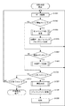
<展開処理フロー>
図6は、本実施形態を示す画像処理装置の制御方法を示すフローチャートである。本例は、図4に示したS1007の展開処理フローの詳細手順である。なお、各ステップは、CPU403が記憶された制御プログラムを実行することで実現される。なお、以下の説明では、CPU403が実行する図3に示したモジュールを主体として説明する。また、本実施形態では、第1の作成処理を開始して、所定の閾値(BlockSize)よりも中間データスプール211に確保できるワークメモリサイズ(WorkSize)が大きいと判断した場合は、第1の変換処理であるベクタ方式のブロック変換処理を実行するが、所定の閾値(BlockSize)よりも中間データスプール211に確保できるワークメモリサイズ(WorkSize)が小さいと判断した場合は、第2の作成処理であるライン方式のブロック変換処理を実行するように制御する。
なお、本実施形態において、第1の作成処理とは、展開処理部205がワークメモリに格納された1バンド分の閉領域データから、ブロック単位のビットマップイメージに相当する閉領域データを取得し、該取得された閉領域データから該ブロック単位のビットマップイメージを生成する処理をいう。以下、第1の作成処理と、第2の作成処理について詳述する。
展開処理においては、展開処理部205がバンド毎に全バンドの処理を行い(S1201〜S1220)、展開処理内でさらにブロック毎に分割してバンド内の全ブロックの画像を出力する(S1205〜S1209、S1212〜S1214)。バンド毎の処理において、S1201でバンド数に応じて、最初にバンドの閉領域データの生成を行う(S1202)。具体的には、展開処理部205がページ単位の中間データから生成される1バンド分の閉領域データを生成する。
<Expansion processing flow>
FIG. 6 is a flowchart showing a control method of the image processing apparatus showing the present embodiment. This example is a detailed procedure of the expansion processing flow of S1007 shown in FIG. Each step is realized by executing the control program stored in the
In the first embodiment, in the first creation process, the
In the expansion process, the
ここで、図14を参照してベクタデータである閉領域データの一例を説明する。例えば、ページ内にオブジェクト1・オブジェクト2・オブジェクト3が重なり合うページ1(透過無し)・ページ2(透過有り)を例に説明する。本実施形態において、ベクタデータは、閉領域と呼ばれるオブジェクトの輪郭で区切られた領域を示す情報から構成される。ライン上の閉領域は、区間でもあるから、1バンド分の閉領域データは1バンドを構成するスキャンライン分の区間データとも言える。
Here, an example of closed region data, which is vector data, will be described with reference to FIG. For example, page 1 (without transparency) and page 2 (with transparency) in which object 1,
そこで、ライン1上の閉領域情報は、閉領域621〜627のように輪郭で区切られた7つの領域から構成される。同様に、ライン2上の閉領域情報も、閉領域631〜637のように輪郭で区切られた7つの領域から構成される。
ベクタデータを構成する各閉領域データは、ライン1,2上の閉領域621〜627、閉領域631〜637の閉領域幅(長さ情報)と閉領域内に含まれるオブジェクトの数を示すオブジェクト個数と、オブジェクト個数が示す閉領域内のオブジェクト情報とで構成される(図14の閉領域データ1400、1401の一例を参照)。ここで、ライン1の閉領域データ641は、ライン1のベクタデータであり、ライン2の閉領域データ642は、ライン2のベクタデータである。なお、1ライン分の閉領域データのサイズは、その1ライン中に含まれる閉領域の数と、各閉領域に含まれる(寄与する)オブジェクトの数に依存する。
Therefore, the closed area information on the
Each closed domain data constituting the vector data is an object indicating the closed domain width (length information) of the closed domains 621 to 627 and the closed domains 631 to 637 on the
図6の説明に戻り、S1201でバンド数分の処理が開始され、S1202では、展開処理部205が所定のバンド高の閉領域データ(ベクタデータ)の生成処理を行う。続いて、展開処理部205が生成した閉領域データをもとにブロック変換で使用するメモリサイズを算出する(S1203)。
次に、展開処理部205は、S1203で算出したブロック変換のメモリサイズ(BlockSize)が中間データスプール211内に確保された一定のワークメモリサイズ(WorkSize)以下であるかどうかを判断する(S1204)。
ここで、展開処理部205がWorkSize≧BlockSize(ブロックサイズ)であると判断した場合、展開処理部205がベクタ方式のブロック変換(第1の変換処理)を行う(S1206)。
次に、展開処理部205がS1208でブロック変換されたベクタデータをラスタ化し(S1207)、展開処理部205がブロック画像を印刷処理部206に出力する(S1208)。これが、バンド内のブロック数分処理され(S1209)、さらに、バンド数分処理が完了したら(S1220)、展開処理を終了する。
一方、S1204でBlockSizeがWorkSizeより大きいと展開処理部205が判断した場合、展開処理部205が中間データを格納する中間データスプール211内に第1の作成処理を開始する際に、あらかじめワークメモリ上に確保されたビットマップメモリのアドレスを取得する(S1210)。そして、展開処理部205は、ライン方式のブロック変換を実行するため、取得したアドレスを先頭とするビットマップメモリ(中間データスプール211に確保される)にバンドのベクタデータをラスタ化したバンド画像データを展開して格納する(S1211)。次に、バンド内のブロック数分、格納されたバンド画像データをブロックごとに印刷処理部206に出力して(S1212〜S1214)、S1220へ進む。
Returning to the description of FIG. 6, processing for the number of bands is started in S1201, and in S1202, the
Next, the
Here, when the
Next, the
On the other hand, when the
<ビットマップメモリ取得フロー>
図7は、本実施形態を示す画像処理装置の制御方法を示すフローチャートである。本例は、図4に示したS1003のビットマップメモリ取得フローの詳細手順である。なお、各ステップは、CPU403が記憶された制御プログラムを実行することで実現される。なお、以下の説明では、CPU403が実行する図3に示したモジュールを主体として説明する。
<Bitmap memory acquisition flow>
FIG. 7 is a flowchart showing a control method of the image processing apparatus showing the present embodiment. This example is a detailed procedure of the bitmap memory acquisition flow of S1003 shown in FIG. Each step is realized by executing the control program stored in the
まず、中間データスプール211上に確保されるビットマップメモリを管理するビットマップメモリ管理情報の一例について図9を参照して説明する。
図9において、ビットマップメモリ管理情報700は、先頭テーブルID701、最後尾テーブルID702、複数のビットマップメモリ管理テーブル707から構成される。先頭テーブルID701は、メモリ取得中に、中間データスプール211上に最初に取得されたビットマップメモリの情報が登録されているビットマップメモリ管理テーブルのIDが設定される。最後尾テーブルID702は、メモリ取得中で最後に取得されたビットマップメモリの情報が登録されているビットマップメモリ管理テーブルのIDが設定される。ビットマップメモリ管理テーブル707は、それぞれビットマップメモリのアドレス704、サイズ705、ページID706が含まれる。
First, an example of bitmap memory management information for managing the bitmap memory secured on the
In FIG. 9, the bitmap memory management information 700 is composed of a first table ID701, a last table ID702, and a plurality of bitmap memory management tables 707. In the
まず、メモリ管理部207は、ビットマップメモリ取得要求がくると、図9に示すビットマップメモリ管理情報700の最後尾テーブルID702+1とテーブル数を比較する(S1301)。ここで、テーブル数とは、ビットマップメモリ管理テーブル707のテーブル数である。
S1301の比較した結果、テーブル数の方が大きいとメモリ管理部207が判断した場合、さらに先頭テーブルID701と最後尾テーブルID702+1とを比較(S1302)し、異なると判断した場合は、メモリ管理部207は、パラメータTableIDに最後尾テーブルID702+1を代入する(S1303)。一方、テーブル数以上で、先頭テーブルID701が1以外(S1304)であるとメモリ管理部207が判断した場合、パラメータTableIDに1を代入する(S1305)。
次に、メモリ管理部207は、ビットマップメモリ管理情報700の最後尾テーブルID702にパラメータTableIDの値を設定する(S1306)。さらに、メモリ管理部207は、展開処理で出力されるバンドのビットマップメモリサイズを以下の式1により算出する(S1307)。
ビットマップメモリサイズ(BMSize)=バンド(ブロック画像)の高さ×バンドの幅×channel数(式1)
First, when a bitmap memory acquisition request comes, the
As a result of comparing S1301, if the
Next, the
Bitmap memory size (BMSize) = band (block image) height x band width x number of channels (Equation 1)
S1308で、メモリ管理部207は、式1に基づいて算出したBMSize分の空きメモリが中間データスプール211から確保できるか否かを判定(S1308)し、空きメモリを確保できるとメモリ管理部207が判断した場合、中間データスプール211から空きメモリを取得する(S1309)。
次に、メモリ管理部207は、取得した空きメモリの先頭アドレスをパラメータTableIDが示す値番目のビットマップメモリ管理テーブルのアドレス704に設定する(S1310)。次に、メモリ管理部207は、ビットマップメモリを使用するページID706を設定して(S1311)、本処理を終了する。
In S1308, the
Next, the
<ビットマップメモリ解放フロー>
図8は、本実施形態を示す画像処理装置の制御方法を示すフローチャートである。本例は、図4に示したS1008のビットマップメモリ解放フローの詳細手順である。なお、各ステップは、CPU403が記憶された制御プログラムを実行することで実現される。なお、以下の説明では、CPU403が実行する図3に示したモジュールを主体として説明する。
メモリ管理部207は、ビットマップメモリ解放要求がくると、先頭テーブルID701が示す値番目のビットマップメモリ管理テーブルのアドレス704を参照し、ビットマップメモリを解放する(S1401)。ビットマップメモリ解放が終了すると、メモリ管理部207は、先頭テーブルID701が示す値番目のテーブルのアドレス704、サイズ705、ページID706を0に変更し、初期状態に戻す(S1402)。
次に、メモリ管理部207は、先頭テーブルID701と最後尾テーブルID702を比較し(S1403)、異なるとメモリ管理部207が判断した場合は、さらに先頭テーブルID701とテーブル数を比較する(S1404)。ここで、先頭テーブルID701とテーブル数が異なる(=最後のテーブル以外)とメモリ管理部207が判断した場合、メモリ管理部207は先頭テーブルID701に1を足して(S1405)、本処理を終了する。
一方、先頭テーブルID701とテーブル数が同じ(=最後のテーブル)であるとメモリ管理部207が判断した場合、先頭テーブルID701に1を設定して(S1406)、本処理を終了する。
<Bitmap memory release flow>
FIG. 8 is a flowchart showing a control method of the image processing apparatus showing the present embodiment. This example is a detailed procedure of the bitmap memory release flow of S1008 shown in FIG. Each step is realized by executing the control program stored in the
When a bitmap memory release request comes, the
Next, the
On the other hand, when the
図10は、ビットマップメモリ管理情報800,810,820と、実際のメモリ、すなわち中間データスプール221上に確保されたビットマップメモリ860〜863、中間データ850〜852を示している。
図10の(A)において、3ページ目の中間データ852の生成後の状態(ビットマップメモリ管理情報800、中間データスプールメモリ801で、図10の(B)に示す4ページ目の中間データ853の生成開始後、メモリ管理部207にビットマップメモリ取得要求(図4のS1003)が来るとする。この場合、メモリ管理部207は、中間データスプール211の中間データスプールメモリ811上に4ページ目のビットマップメモリ863と中間データ853を確保(中間データスプールメモリ211(図10の(B)参照)し、ビットマップメモリ管理情報800の最後部テーブルID831の3をビットマップメモリ管理情報810の最後部テーブルID831に示すように4に変更する。
また、4番目のビットマップメモリ管理テーブル845に取得したビットマップメモリのアドレス840、サイズ841、ページID842を設定する(ビットマップメモリ管理情報810(図10の(B)参照))。
次に、1ページ目の展開処理(S1007)が終了し、メモリ管理部207にビットマップメモリ解放要求が来るとする(S1008)。
この場合、メモリ管理部207は、図10の(C)に示すように中間データスプール211の中間データスプールメモリ821上の1ページ目のビットマップイメージを格納するビットマップメモリ860と中間データ850を解放し、ビットマップメモリ管理情報820の先頭テーブルID830を1から2に変更する。
その際、さらに、メモリ管理部207は、図10の(A)に示す1番目のビットマップメモリ管理テーブル845に取得したビットマップメモリのアドレス840、サイズ841、ページID842を0に初期化する(ビットマップメモリ管理情報820(図10の(C))。
本実施形態によれば、第1のブロック順変換処理を第2のブロック順変換処理に切り替える際、展開処理時に使用するビットマップメモリ(中間データスプール211上に確保されるワークメモリ)を各ページの中間データを生成する時にあらかじめ確保しておくことで、展開処理時のメモリ空き待ちが発生しないブロック順変換処理を実現することできる。
FIG. 10 shows bitmap memory management information 800,810,820, actual memory, that is,
In (A) of FIG. 10, the state after generation of the
In addition, the
Next, suppose that the expansion process (S1007) of the first page is completed, and a bitmap memory release request comes to the memory management unit 207 (S1008).
In this case, the
At that time, the
According to the present embodiment, when switching the first block order conversion process to the second block order conversion process, the bitmap memory (work memory secured on the intermediate data spool 211) used in the expansion process is set on each page. By securing in advance when generating the intermediate data of, it is possible to realize the block order conversion process in which the memory free wait during the expansion process does not occur.
〔第2実施形態〕
第1実施形態では、中間データ生成時にページ毎にビットマップメモリを確保する場合について説明した。以下、第2実施形態では、第1のタイル変換処理を実行する際に、第2のタイル変換処理に備えてあらかじめ各ページで共通に使用するビットマップメモリを取得し、当該ビットマップメモリの解放情報を管理することにより、最初に確保したビットマップメモリをページ間で共有する例を説明する。
[Second Embodiment]
In the first embodiment, a case where a bitmap memory is secured for each page at the time of intermediate data generation has been described. Hereinafter, in the second embodiment, when the first tile conversion process is executed, the bitmap memory commonly used on each page is acquired in advance in preparation for the second tile conversion process, and the bitmap memory is released. An example of sharing the first allocated bitmap memory between pages by managing the information will be described.
<ビットマップメモリ取得フロー>
図11は、本実施形態を示す画像処理装置の制御方法を示すフローチャートである。本例は、図4に示したS1003のビットマップメモリ取得フローの詳細手順である。なお、各ステップは、CPU403が記憶された制御プログラムを実行することで実現される。なお、以下の説明では、CPU403が実行する図3に示したモジュールを主体として説明する。
メモリ管理部207は、ビットマップメモリ取得の要求がくると、展開処理で出力されるバンドのビットマップメモリサイズを(上述した式1)により算出する(S1501)。
次に、メモリ管理部207は、既に確保されているビットマップメモリがあるかを調べるため、先頭テーブルID1311が示す値番目のビットマップメモリ管理テーブル1301(図13)を参照し(S1502、S1503)、アドレス1313が0以外でサイズ1314がBMSize以上かを判定する(S1504)。ここで、アドレス1313が0以外でサイズ1314がBMSize以上であるとメモリ管理部207が判断した場合は、メモリ管理部207は、先頭テーブルID1311が示す値番目のページID1315を更新する(S1505)。
<Bitmap memory acquisition flow>
FIG. 11 is a flowchart showing a control method of the image processing apparatus showing the present embodiment. This example is a detailed procedure of the bitmap memory acquisition flow of S1003 shown in FIG. Each step is realized by executing the control program stored in the
When a request for acquiring a bitmap memory arrives, the
Next, the
一方、S1504の判定で該当しないとメモリ管理部207が判断した場合は、図13の(A)に示すビットマップメモリ管理情報1300の最後尾テーブルID1310+1とテーブル数を比較する(S1510)。この比較した結果、テーブル数の方が大きいとメモリ管理部207が判断した場合、さらに先頭テーブルID1311と最後尾テーブルID1310+1を比較する(S1511)。ここで、メモリ管理部207が先頭テーブルID1311と最後尾テーブルID1312+1とが異なると判断した場合は、メモリ管理部207は、パラメータTableIDに最後尾テーブルID1312+1を代入する(S1512)。
一方、テーブル数以上で、先頭テーブルID1311が1以外(S1513)であるとメモリ管理部207が判断した場合、パラメータTableIDに1を代入する(S1514)。そして、メモリ管理部207は、ビットマップメモリ管理情報1310の最後尾テーブルID1312にパラメータTableIDが示す値を設定する(S1515)。
次に、メモリ管理部207は、S1501で算出したBMSize分の空きメモリが中間データスプール211の中間データスプールメモリに確保できるか否かを判定し(S1516)、空きメモリを確保できるとメモリ管理部207が判断した場合、中間データスプール211の中間データスプールメモリからBMSize分の空きメモリを取得する(S1517)。
次に、メモリ管理部207は、取得したBMSize分の空きメモリの先頭アドレスをパラメータTableIDが示す値番目のビットマップメモリ管理テーブル1301の先頭アドレス1313に設定する(S1518)。また、メモリ管理部207は、ビットマップメモリ1314を使用するページID1315を設定して(S1505)、本処理を終了する。
On the other hand, when the
On the other hand, if the number of tables is greater than or equal to the number of tables and the
Next, the
Next, the
<ビットマップメモリ解放フロー>
図12は、本実施形態を示す画像処理装置の制御方法を示すフローチャートである。本例は、S1008のビットマップメモリ解放フローの詳細手順である。なお、各ステップは、CPU403が記憶された制御プログラムを実行することで実現される。なお、以下の説明では、CPU403が実行する図3に示したモジュールを主体として説明する。
メモリ管理部207は、ビットマップメモリ解放要求がくると、先頭テーブルID1311が示す値番目のビットマップメモリ管理情報を参照し(S1601)、ページID1315と解放ページIDを比較する(S1602)。ここで、ページID1315と解放ページIDが同じであるとメモリ管理部207が判断した場合は、先頭テーブルID1311の1番目のビットマップ管理情報1310のアドレス1313を参照し、ビットマップメモリ1314を解放する(S1603)。
そして、ビットマップメモリ1314の解放が終了すると、メモリ管理部207は、先頭テーブルID1311が示す値番目のテーブルのアドレス1313、サイズ1314、ページID1315を0に変更し、初期状態に戻す(S1604)。
<Bitmap memory release flow>
FIG. 12 is a flowchart showing a control method of the image processing apparatus showing the present embodiment. This example is a detailed procedure of the bitmap memory release flow of S1008. Each step is realized by executing the control program stored in the
When the bitmap memory release request comes, the
Then, when the release of the
次に、メモリ管理部207は、先頭テーブルID1311と最後尾テーブルID1312を比較し(S1605)、異なるとメモリ管理部207が判断した場合は、さらに先頭テーブルID1311が示す値とテーブル数を比較する(S1606)。ここで、先頭テーブルID1311とテーブル数が異なる(=最後のテーブル以外)とメモリ管理部207が判断した場合、先頭テーブルID1311のページID1315に1を足して(S1607)、本処理を終了する。
一方、先頭テーブルID1311が示す値とテーブル数が同じ(=最後のテーブル)であるとメモリ管理部207が判断した場合、先頭テーブルID1311のページID1315に1を設定して(S1608)、処理を終了する。
Next, the
On the other hand, when the
一方、S1602でページID1315と解放ページIDが異なるとメモリ管理部207が判断した場合、メモリ管理部207は、最後尾テーブルID1312で特定される最後部IDが示す値番目のビットマップメモリ管理情報910を参照し(S1610)、解放ページIDと同じページID1315のビットマップメモリ管理テーブル1301が見つかるまで(S1614)、S1610〜S1614を繰り返し実行する。
そして、解放ページIDと同じページID1315のビットマップメモリ管理テーブル1301が見つかったとメモリ管理部207が判断した場合(S1614)、該当のビットマップメモリ管理テーブル1301のアドレス1313を参照し、ビットマップメモリ1314を解放する(S1615)。
このようにしてビットマップメモリ解放が終了すると、メモリ管理部207は、先頭テーブルID1311のアドレス1313、サイズ1314、ページID1315を0に変更し、初期状態に戻す(S1616)。
次に、最後尾テーブルID1312が示す値とテーブル数を比較し(S1617)、異なるとメモリ管理部207が判断した場合は、さらに最後尾テーブルID1312のページID1315が示す値が1であるかを判定する(S1618)。最後尾テーブルID1312のページID1315が示す値が1ではない(=先頭のテーブル以外)とメモリ管理部207が判断した場合、最後尾テーブルID1312のページID1315から1を引いて(S1619)、本処理を終了する。
一方、最後尾テーブルID1312のページID1315が示す値が1である(=先頭のテーブル)とメモリ管理部207が判断した場合、最後尾テーブルID1312にテーブル数を設定して(S1620)、本処理を終了する。
On the other hand, when the
Then, when the
When the bitmap memory release is completed in this way, the
Next, the value indicated by the
On the other hand, when the
図13は、ビットマップメモリ管理情報1300、1310と、実際の中間データスプール211上に確保されたビットマップメモリ1314、中間データ1316,1317,1319を示している。
図13において、3ページ目の中間データ生成後の状態(ビットマップメモリ管理情報800、810)で、1ページ目の中間データ生成後の状態に対応するビットマップメモリ管理情報1300、1310で、2,3,4ページ目の中間データ1317,1318,1319の生成開始後、メモリ管理部207にビットマップメモリ取得要求(S1003)が来るとする。この場合、中間データスプール211上には4ページ目の中間データ1319だけが確保され、メモリ管理部207がビットマップメモリ管理テーブル1301のページID1315を1→4に更新するだけで、1ページ目に確保されたビットマップメモリ1314をそのまま使えるようになる。
FIG. 13 shows bitmap memory management information 1300, 1310, and
In FIG. 13, in the state after the intermediate data generation on the third page (bitmap memory management information 800, 810), the bitmap memory management information 1300, 1310 corresponding to the state after the intermediate data generation on the first page, 2 , It is assumed that a bitmap memory acquisition request (S1003) comes to the
このように、第1の変換処理から第2の変換処理に切り替わる際、第2の変換処理に伴う展開処理時に使用するビットマップメモリを中間データ生成時にあらかじめ確保し、かつ前ページでビットマップメモリが既に確保されているかどうかを判定する。これにより、ビットマップメモリの使用サイズを抑えることができるようになる。 In this way, when switching from the first conversion process to the second conversion process, the bitmap memory used in the expansion process associated with the second conversion process is secured in advance at the time of intermediate data generation, and the bitmap memory is stored on the previous page. Determines if is already secured. This makes it possible to reduce the size of the bitmap memory used.
本発明は、上述の実施形態の1以上の機能を実現するプログラムを、ネットワーク又は記憶媒体を介してシステムまたは装置に供給し、そのシステム又は装置のコンピュータにおける1つ以上のプロセッサがプログラムを読み出し実行する処理でも実現可能である。また、1以上の機能を実現する回路(例えばASIC)によっても実現可能である。 The present invention supplies a program that realizes one or more functions of the above-described embodiment to a system or device via a network or storage medium, and one or more processors in the computer of the system or device reads and executes the program. It can also be realized by the processing to be performed. It can also be realized by a circuit (for example, ASIC) that realizes one or more functions.
101 画像形成装置
102 画像処理装置
103 ネットワーク
207 メモリ管理部
211 中間データスプール
101 Image forming device
102 Image processing equipment
103 network
207 Memory Management Department
211 Intermediate data spool
Claims (7)
装置であって、
ページ単位の中間データから生成される1バンド分の閉領域データを生成する生成手段
と、
前記生成手段が生成した1バンド分の閉領域データを前記中間データメモリに確保され
るワークメモリに格納し、該格納された1バンド分の閉領域データからブロック単位のビ
ットマップイメージを作成する第1の作成手段と、
ページ単位の中間データから生成される1バンド分の閉領域データから1バンド分のビ
ットマップイメージを前記中間データメモリに確保されるワークメモリに展開し、該ワー
クメモリに展開した1バンド分のビットマップイメージからブロック単位のビットマップ
イメージを作成する第2の作成手段と、
前記中間データメモリから確保するワークメモリのサイズがブロック変換に使用するブ
ロックサイズを超えているかどうかを判断する判断手段と、
前記判断手段が前記ワークメモリのサイズが前記ブロックサイズを超えていると判断し
た場合、前記第1の作成手段がビットマップを作成する処理を前記第2の作成手段がビッ
トマップを作成する処理に切り替える制御手段と、
前記第1の作成手段がビットマップを作成する処理を開始する場合、前記ワークメモリ
に前記第2の作成手段で使用するビットマップメモリをあらかじめ確保するメモリ管理手
段と、
を備えることを特徴とする画像処理装置。 An image processing device that stores and processes intermediate data generated from print data in an intermediate data memory.
A generation means for generating closed area data for one band generated from intermediate data for each page,
The closed area data for one band generated by the generation means is stored in the work memory secured in the intermediate data memory, and the bitmap image for each block is created from the stored closed area data for one band. 1 creation method and
One band of bitmap images generated from one band of closed area data generated from page-by-page intermediate data is expanded into the work memory secured in the intermediate data memory, and one band of bits expanded in the work memory. A second means of creating a block-by-block bitmap image from a map image,
A means for determining whether the size of the work memory allocated from the intermediate data memory exceeds the block size used for block conversion, and
When the determination means determines that the size of the work memory exceeds the block size, the process of creating the bitmap by the first creation means becomes the process of creating the bitmap by the second creation means. Control means to switch and
When the first creating means starts the process of creating a bitmap, the memory management means for allocating the bitmap memory used in the second creating means in the work memory in advance, and the memory management means.
An image processing device characterized by comprising.
段がビットマップを作成する処理に切り替えた場合、前記第2の作成手段は、前記メモリ
管理手段が確保しているビットマップメモリを使用して1バンド分のビットマップイメー
ジからブロック単位のビットマップイメージを作成することを特徴とする請求項1に記載
の画像処理装置。 When the control means switches the process of the first creating means to create a bitmap to the process of the second creating means creating a bitmap, the memory management means secures the second creating means. The image processing apparatus according to claim 1, wherein a block-based bitmap image is created from a one-band bitmap image using the bitmap memory.
場合、前記ワークメモリに前記第2の作成手段で使用するビットマップメモリを各ページ
毎に確保することを特徴とする請求項1に記載の画像処理装置。 The memory management means is characterized in that when the first creating means starts a process of creating a bitmap, the work memory is secured with a bitmap memory used by the second creating means for each page. The image processing apparatus according to claim 1.
場合、前記ワークメモリに前記第2の作成手段で使用する各ページで共通に使用するビッ
トマップメモリを1つ確保することを特徴とする請求項1に記載の画像処理装置。 When the first creating means starts a process of creating a bitmap, the memory management means uses the work memory as one bitmap memory commonly used on each page used by the second creating means. The image processing apparatus according to claim 1, wherein the image processing apparatus is secured.
、ブロック単位のビットマップイメージに相当する閉領域データを取得し、該取得された
閉領域データから該ブロック単位のビットマップイメージを生成することを特徴とする請
求項1乃至4の何れか1項に記載の画像処理装置。 The first creation means acquires closed area data corresponding to a bitmap image in block units from the closed area data for one band stored in the work memory, and blocks the blocks from the acquired closed area data. The image processing apparatus according to any one of claims 1 to 4, wherein a bitmap image of a unit is generated.
装置の制御方法であって、
ページ単位の中間データから生成される1バンド分の閉領域データを生成する生成工程
と、
前記生成工程で生成した1バンド分の閉領域データを前記中間データメモリに確保され
るワークメモリに格納し、該格納された1バンド分の閉領域データからブロック単位のビ
ットマップイメージを作成する第1の作成工程と、
ページ単位の中間データから生成される1バンド分の閉領域データから1バンド分のビ
ットマップイメージを前記中間データメモリに確保されるワークメモリに展開し、該ワー
クメモリに展開した1バンド分のビットマップイメージからブロック単位のビットマップ
イメージを作成する第2の作成工程と、
前記中間データメモリから確保するワークメモリのサイズがブロック変換に使用するブ
ロックサイズを超えているかどうかを判断する判断工程と、
前記判断工程で前記ワークメモリのサイズが前記ブロックサイズを超えていると判断し
た場合、前記第1の作成工程がビットマップを作成する処理を前記第2の作成工程がビッ
トマップを作成する処理に切り替える制御工程と、
前記第1の作成工程がビットマップを作成する処理を開始する場合、前記ワークメモリ
に前記第2の作成工程がビットマップを作成する処理で使用するビットマップメモリをあ
らかじめ確保するメモリ管理工程と、
を備えることを特徴とする画像処理装置の制御方法。 It is a control method of an image processing device that stores and processes intermediate data generated from print data in an intermediate data memory.
A generation process that generates closed area data for one band generated from intermediate data for each page,
The closed area data for one band generated in the generation step is stored in the work memory secured in the intermediate data memory, and the bitmap image for each block is created from the stored closed area data for one band. 1 creation process and
One band of bitmap images generated from one band of closed area data generated from page-by-page intermediate data is expanded into the work memory secured in the intermediate data memory, and one band of bits expanded in the work memory. The second creation process to create a block-by-block bitmap image from the map image,
A determination process for determining whether the size of the work memory secured from the intermediate data memory exceeds the block size used for block conversion, and a determination process.
When it is determined in the determination step that the size of the work memory exceeds the block size, the process of creating the bitmap by the first creation step becomes the process of creating the bitmap by the second creation step. Control process to switch and
When the first creation step starts the process of creating a bitmap, the memory management step of allocating the bitmap memory used in the process of creating the bitmap in the work memory in advance by the second creation step
A method for controlling an image processing apparatus, which comprises.
るプログラム。 A program characterized in that a computer executes the control method of the image processing device according to claim 6.
Priority Applications (2)
| Application Number | Priority Date | Filing Date | Title |
|---|---|---|---|
| JP2016154834A JP6789716B2 (en) | 2016-08-05 | 2016-08-05 | Image processing device, control method of image processing device, and program |
| US15/666,416 US10102458B2 (en) | 2016-08-05 | 2017-08-01 | Image processing apparatus for generating intermediate data and processing the intermediate data, method of processing intermediate data generated from print data |
Applications Claiming Priority (1)
| Application Number | Priority Date | Filing Date | Title |
|---|---|---|---|
| JP2016154834A JP6789716B2 (en) | 2016-08-05 | 2016-08-05 | Image processing device, control method of image processing device, and program |
Publications (3)
| Publication Number | Publication Date |
|---|---|
| JP2018020536A JP2018020536A (en) | 2018-02-08 |
| JP2018020536A5 JP2018020536A5 (en) | 2019-09-05 |
| JP6789716B2 true JP6789716B2 (en) | 2020-11-25 |
Family
ID=61069317
Family Applications (1)
| Application Number | Title | Priority Date | Filing Date |
|---|---|---|---|
| JP2016154834A Active JP6789716B2 (en) | 2016-08-05 | 2016-08-05 | Image processing device, control method of image processing device, and program |
Country Status (2)
| Country | Link |
|---|---|
| US (1) | US10102458B2 (en) |
| JP (1) | JP6789716B2 (en) |
Families Citing this family (1)
| Publication number | Priority date | Publication date | Assignee | Title |
|---|---|---|---|---|
| US10866769B2 (en) * | 2019-02-26 | 2020-12-15 | Ricoh Company, Ltd. | Data cache synchronization in two-phase printing processes |
Family Cites Families (9)
| Publication number | Priority date | Publication date | Assignee | Title |
|---|---|---|---|---|
| JP2001205868A (en) * | 2000-01-31 | 2001-07-31 | Canon Inc | Printing apparatus, information-transmitting apparatus, printing system, method for controlling them, and memory medium |
| US7145669B2 (en) * | 2003-01-28 | 2006-12-05 | Hewlett-Packard Development Company, L.P. | Partially pre-rasterizing image data |
| US7003597B2 (en) * | 2003-07-09 | 2006-02-21 | International Business Machines Corporation | Dynamic reallocation of data stored in buffers based on packet size |
| JP4337885B2 (en) * | 2007-02-15 | 2009-09-30 | コニカミノルタビジネステクノロジーズ株式会社 | Image forming apparatus and image forming method |
| JP4918871B2 (en) * | 2007-02-27 | 2012-04-18 | セイコーエプソン株式会社 | Printer and control method thereof |
| JP5662675B2 (en) * | 2009-12-04 | 2015-02-04 | キヤノン株式会社 | Image forming apparatus and control method thereof |
| JP5747489B2 (en) * | 2010-11-30 | 2015-07-15 | 富士ゼロックス株式会社 | Printed document processing system, cache device, and program |
| JP6029344B2 (en) * | 2012-06-20 | 2016-11-24 | キヤノン株式会社 | Image processing apparatus, image processing method, and program |
| JP6643056B2 (en) * | 2015-11-19 | 2020-02-12 | キヤノン株式会社 | Image processing apparatus, image processing method, data generation method, and program |
-
2016
- 2016-08-05 JP JP2016154834A patent/JP6789716B2/en active Active
-
2017
- 2017-08-01 US US15/666,416 patent/US10102458B2/en active Active
Also Published As
| Publication number | Publication date |
|---|---|
| US20180039870A1 (en) | 2018-02-08 |
| US10102458B2 (en) | 2018-10-16 |
| JP2018020536A (en) | 2018-02-08 |
Similar Documents
| Publication | Publication Date | Title |
|---|---|---|
| JP2016162238A (en) | Image processing system, processing execution control apparatus, image formation and output control apparatus, control program for image processing system, and control method of image processing system | |
| JP2005269629A (en) | Printing system, printing control method and printing system program | |
| JP6412365B2 (en) | Image processing apparatus, control method therefor, and image processing system | |
| JP6289276B2 (en) | Information processing apparatus, program, and control method | |
| JP2015157473A (en) | Image forming apparatus, information processing method, and program | |
| JP2019025801A (en) | Printing system, printer and control method thereof, and program | |
| JP6789716B2 (en) | Image processing device, control method of image processing device, and program | |
| JP5739639B2 (en) | Image forming apparatus, image forming method, and program | |
| JP4124898B2 (en) | Information processing system, information processing apparatus and method | |
| JP4912360B2 (en) | Information processing apparatus, information processing method, and program | |
| JP6455457B2 (en) | Image forming output control device, control program for image forming output control device, control method for image forming output control device, and image processing system | |
| JP5842590B2 (en) | Image processing apparatus and control program for image processing apparatus | |
| US10310788B2 (en) | Control method for generating data used for printing and information processing apparatus | |
| JP6381311B2 (en) | Image forming apparatus, image forming method, and program | |
| JP2019086987A (en) | Image forming device, control method thereof, and program | |
| JP6524854B2 (en) | IMAGE PROCESSING SYSTEM, PROCESSING EXECUTION CONTROL DEVICE, IMAGE PROCESSING METHOD, AND CONTROL PROGRAM | |
| JP2018206311A (en) | Printing system, server and control method thereof and program | |
| JP7158895B2 (en) | Information processing device, its control method, and program | |
| JP2010250393A (en) | Information processing apparatus and information processing method | |
| JP5516551B2 (en) | Image forming system and image forming control method | |
| JP4335852B2 (en) | Print control apparatus, print control method, and program | |
| JP6477359B2 (en) | Image processing system, process execution control device, image processing method, and control program | |
| JP6886338B2 (en) | Image forming device, its control method, and program | |
| JP2012164207A (en) | Workflow processing device, information processing method and program | |
| JP7091115B2 (en) | Image forming device, control method of image forming device, and program |
Legal Events
| Date | Code | Title | Description |
|---|---|---|---|
| RD02 | Notification of acceptance of power of attorney |
Free format text: JAPANESE INTERMEDIATE CODE: A7422 Effective date: 20180306 |
|
| A521 | Request for written amendment filed |
Free format text: JAPANESE INTERMEDIATE CODE: A523 Effective date: 20190724 |
|
| A621 | Written request for application examination |
Free format text: JAPANESE INTERMEDIATE CODE: A621 Effective date: 20190724 |
|
| A977 | Report on retrieval |
Free format text: JAPANESE INTERMEDIATE CODE: A971007 Effective date: 20200529 |
|
| A131 | Notification of reasons for refusal |
Free format text: JAPANESE INTERMEDIATE CODE: A131 Effective date: 20200714 |
|
| A521 | Request for written amendment filed |
Free format text: JAPANESE INTERMEDIATE CODE: A523 Effective date: 20200731 |
|
| TRDD | Decision of grant or rejection written | ||
| A01 | Written decision to grant a patent or to grant a registration (utility model) |
Free format text: JAPANESE INTERMEDIATE CODE: A01 Effective date: 20201006 |
|
| A61 | First payment of annual fees (during grant procedure) |
Free format text: JAPANESE INTERMEDIATE CODE: A61 Effective date: 20201104 |
|
| R151 | Written notification of patent or utility model registration |
Ref document number: 6789716 Country of ref document: JP Free format text: JAPANESE INTERMEDIATE CODE: R151 |