JP6789129B2 - Conductive polymer composite - Google Patents
Conductive polymer composite Download PDFInfo
- Publication number
- JP6789129B2 JP6789129B2 JP2017002432A JP2017002432A JP6789129B2 JP 6789129 B2 JP6789129 B2 JP 6789129B2 JP 2017002432 A JP2017002432 A JP 2017002432A JP 2017002432 A JP2017002432 A JP 2017002432A JP 6789129 B2 JP6789129 B2 JP 6789129B2
- Authority
- JP
- Japan
- Prior art keywords
- metal
- composite
- conductive polymer
- carbon nanotubes
- conductive
- Prior art date
- Legal status (The legal status is an assumption and is not a legal conclusion. Google has not performed a legal analysis and makes no representation as to the accuracy of the status listed.)
- Active
Links
- 239000002131 composite material Substances 0.000 title claims description 131
- 229920001940 conductive polymer Polymers 0.000 title claims description 52
- 239000002041 carbon nanotube Substances 0.000 claims description 66
- OKTJSMMVPCPJKN-UHFFFAOYSA-N Carbon Chemical compound [C] OKTJSMMVPCPJKN-UHFFFAOYSA-N 0.000 claims description 57
- 229910021393 carbon nanotube Inorganic materials 0.000 claims description 55
- 229910052751 metal Inorganic materials 0.000 claims description 46
- 239000002184 metal Substances 0.000 claims description 46
- 229910052709 silver Inorganic materials 0.000 claims description 40
- BQCADISMDOOEFD-UHFFFAOYSA-N Silver Chemical compound [Ag] BQCADISMDOOEFD-UHFFFAOYSA-N 0.000 claims description 38
- 239000004332 silver Substances 0.000 claims description 38
- 229920001169 thermoplastic Polymers 0.000 claims description 35
- 238000000034 method Methods 0.000 claims description 27
- 229920001610 polycaprolactone Polymers 0.000 claims description 26
- 239000007788 liquid Substances 0.000 claims description 19
- 229920000642 polymer Polymers 0.000 claims description 16
- 238000010146 3D printing Methods 0.000 claims description 14
- 238000007747 plating Methods 0.000 claims description 12
- 239000000203 mixture Substances 0.000 claims description 11
- RYGMFSIKBFXOCR-UHFFFAOYSA-N Copper Chemical compound [Cu] RYGMFSIKBFXOCR-UHFFFAOYSA-N 0.000 claims description 8
- 229910052802 copper Inorganic materials 0.000 claims description 8
- 239000010949 copper Substances 0.000 claims description 8
- KDLHZDBZIXYQEI-UHFFFAOYSA-N Palladium Chemical compound [Pd] KDLHZDBZIXYQEI-UHFFFAOYSA-N 0.000 claims description 7
- 239000002270 dispersing agent Substances 0.000 claims description 7
- PCHJSUWPFVWCPO-UHFFFAOYSA-N gold Chemical compound [Au] PCHJSUWPFVWCPO-UHFFFAOYSA-N 0.000 claims description 7
- 229910052737 gold Inorganic materials 0.000 claims description 7
- 239000010931 gold Substances 0.000 claims description 7
- -1 poly (styrene ethylene butylene styrene Chemical class 0.000 claims description 7
- 239000004632 polycaprolactone Substances 0.000 claims description 7
- 239000004626 polylactic acid Substances 0.000 claims description 7
- PXHVJJICTQNCMI-UHFFFAOYSA-N Nickel Chemical compound [Ni] PXHVJJICTQNCMI-UHFFFAOYSA-N 0.000 claims description 6
- 238000010438 heat treatment Methods 0.000 claims description 6
- 239000004014 plasticizer Substances 0.000 claims description 6
- 239000004094 surface-active agent Substances 0.000 claims description 6
- VSKJLJHPAFKHBX-UHFFFAOYSA-N 2-methylbuta-1,3-diene;styrene Chemical compound CC(=C)C=C.C=CC1=CC=CC=C1.C=CC1=CC=CC=C1 VSKJLJHPAFKHBX-UHFFFAOYSA-N 0.000 claims description 4
- 229910052755 nonmetal Inorganic materials 0.000 claims description 4
- 229910052763 palladium Inorganic materials 0.000 claims description 4
- 239000000758 substrate Substances 0.000 claims description 4
- 229910017052 cobalt Inorganic materials 0.000 claims description 3
- 239000010941 cobalt Substances 0.000 claims description 3
- GUTLYIVDDKVIGB-UHFFFAOYSA-N cobalt atom Chemical compound [Co] GUTLYIVDDKVIGB-UHFFFAOYSA-N 0.000 claims description 3
- 229910052759 nickel Inorganic materials 0.000 claims description 3
- 239000000956 alloy Substances 0.000 claims description 2
- 229910045601 alloy Inorganic materials 0.000 claims description 2
- 239000004693 Polybenzimidazole Substances 0.000 claims 4
- 229920002480 polybenzimidazole Polymers 0.000 claims 4
- 229920001054 Poly(ethylene‐co‐vinyl acetate) Polymers 0.000 claims 3
- 229920001200 poly(ethylene-vinyl acetate) Polymers 0.000 claims 3
- 239000003795 chemical substances by application Substances 0.000 claims 1
- 239000002048 multi walled nanotube Substances 0.000 description 44
- 239000000463 material Substances 0.000 description 24
- 239000002245 particle Substances 0.000 description 15
- 239000002105 nanoparticle Substances 0.000 description 9
- 238000001125 extrusion Methods 0.000 description 8
- 238000007772 electroless plating Methods 0.000 description 7
- 230000008569 process Effects 0.000 description 7
- 239000002904 solvent Substances 0.000 description 7
- 230000000052 comparative effect Effects 0.000 description 6
- 239000004020 conductor Substances 0.000 description 6
- 238000000465 moulding Methods 0.000 description 6
- 229920001577 copolymer Polymers 0.000 description 5
- 229920003023 plastic Polymers 0.000 description 5
- 239000004033 plastic Substances 0.000 description 5
- 238000007639 printing Methods 0.000 description 5
- 238000001878 scanning electron micrograph Methods 0.000 description 5
- 238000012360 testing method Methods 0.000 description 5
- WSFSSNUMVMOOMR-UHFFFAOYSA-N Formaldehyde Chemical compound O=C WSFSSNUMVMOOMR-UHFFFAOYSA-N 0.000 description 4
- ZMXDDKWLCZADIW-UHFFFAOYSA-N N,N-Dimethylformamide Chemical compound CN(C)C=O ZMXDDKWLCZADIW-UHFFFAOYSA-N 0.000 description 4
- FOIXSVOLVBLSDH-UHFFFAOYSA-N Silver ion Chemical compound [Ag+] FOIXSVOLVBLSDH-UHFFFAOYSA-N 0.000 description 4
- NIXOWILDQLNWCW-UHFFFAOYSA-M acrylate group Chemical group C(C=C)(=O)[O-] NIXOWILDQLNWCW-UHFFFAOYSA-M 0.000 description 4
- 229910052782 aluminium Inorganic materials 0.000 description 4
- XAGFODPZIPBFFR-UHFFFAOYSA-N aluminium Chemical compound [Al] XAGFODPZIPBFFR-UHFFFAOYSA-N 0.000 description 4
- 238000000151 deposition Methods 0.000 description 4
- 238000002149 energy-dispersive X-ray emission spectroscopy Methods 0.000 description 4
- 150000002739 metals Chemical class 0.000 description 4
- 238000002156 mixing Methods 0.000 description 4
- VEXZGXHMUGYJMC-UHFFFAOYSA-N Hydrochloric acid Chemical compound Cl VEXZGXHMUGYJMC-UHFFFAOYSA-N 0.000 description 3
- YXFVVABEGXRONW-UHFFFAOYSA-N Toluene Chemical compound CC1=CC=CC=C1 YXFVVABEGXRONW-UHFFFAOYSA-N 0.000 description 3
- 239000004676 acrylonitrile butadiene styrene Substances 0.000 description 3
- 239000000654 additive Substances 0.000 description 3
- 229920005601 base polymer Polymers 0.000 description 3
- 238000000576 coating method Methods 0.000 description 3
- 239000002482 conductive additive Substances 0.000 description 3
- 230000006870 function Effects 0.000 description 3
- 238000005259 measurement Methods 0.000 description 3
- 230000007246 mechanism Effects 0.000 description 3
- 239000000178 monomer Substances 0.000 description 3
- 239000002071 nanotube Substances 0.000 description 3
- 229920002981 polyvinylidene fluoride Polymers 0.000 description 3
- 229910017745 AgNP Inorganic materials 0.000 description 2
- IAZDPXIOMUYVGZ-UHFFFAOYSA-N Dimethylsulphoxide Chemical compound CS(C)=O IAZDPXIOMUYVGZ-UHFFFAOYSA-N 0.000 description 2
- 101150003085 Pdcl gene Proteins 0.000 description 2
- 239000004698 Polyethylene Substances 0.000 description 2
- 239000004743 Polypropylene Substances 0.000 description 2
- 239000004793 Polystyrene Substances 0.000 description 2
- 206010070834 Sensitisation Diseases 0.000 description 2
- PPBRXRYQALVLMV-UHFFFAOYSA-N Styrene Chemical compound C=CC1=CC=CC=C1 PPBRXRYQALVLMV-UHFFFAOYSA-N 0.000 description 2
- 238000010276 construction Methods 0.000 description 2
- 230000008021 deposition Effects 0.000 description 2
- 150000002500 ions Chemical class 0.000 description 2
- 238000012986 modification Methods 0.000 description 2
- 230000004048 modification Effects 0.000 description 2
- 230000003647 oxidation Effects 0.000 description 2
- 238000007254 oxidation reaction Methods 0.000 description 2
- 239000003973 paint Substances 0.000 description 2
- 229920000058 polyacrylate Polymers 0.000 description 2
- 229920000728 polyester Polymers 0.000 description 2
- 229920000573 polyethylene Polymers 0.000 description 2
- 239000002861 polymer material Substances 0.000 description 2
- 229920000307 polymer substrate Polymers 0.000 description 2
- 229920001155 polypropylene Polymers 0.000 description 2
- 229920002223 polystyrene Polymers 0.000 description 2
- 238000012545 processing Methods 0.000 description 2
- 230000009467 reduction Effects 0.000 description 2
- 239000000523 sample Substances 0.000 description 2
- 230000008313 sensitization Effects 0.000 description 2
- 238000001228 spectrum Methods 0.000 description 2
- 230000002195 synergetic effect Effects 0.000 description 2
- 239000004416 thermosoftening plastic Substances 0.000 description 2
- 229920002554 vinyl polymer Polymers 0.000 description 2
- BQCIDUSAKPWEOX-UHFFFAOYSA-N 1,1-Difluoroethene Chemical compound FC(F)=C BQCIDUSAKPWEOX-UHFFFAOYSA-N 0.000 description 1
- OMIHGPLIXGGMJB-UHFFFAOYSA-N 7-oxabicyclo[4.1.0]hepta-1,3,5-triene Chemical group C1=CC=C2OC2=C1 OMIHGPLIXGGMJB-UHFFFAOYSA-N 0.000 description 1
- 101710134784 Agnoprotein Proteins 0.000 description 1
- KXDHJXZQYSOELW-UHFFFAOYSA-N Carbamic acid Chemical group NC(O)=O KXDHJXZQYSOELW-UHFFFAOYSA-N 0.000 description 1
- 239000004593 Epoxy Substances 0.000 description 1
- VGGSQFUCUMXWEO-UHFFFAOYSA-N Ethene Chemical group C=C VGGSQFUCUMXWEO-UHFFFAOYSA-N 0.000 description 1
- 239000005977 Ethylene Substances 0.000 description 1
- FXHOOIRPVKKKFG-UHFFFAOYSA-N N,N-Dimethylacetamide Chemical compound CN(C)C(C)=O FXHOOIRPVKKKFG-UHFFFAOYSA-N 0.000 description 1
- SECXISVLQFMRJM-UHFFFAOYSA-N N-Methylpyrrolidone Chemical compound CN1CCCC1=O SECXISVLQFMRJM-UHFFFAOYSA-N 0.000 description 1
- GRYLNZFGIOXLOG-UHFFFAOYSA-N Nitric acid Chemical compound O[N+]([O-])=O GRYLNZFGIOXLOG-UHFFFAOYSA-N 0.000 description 1
- 239000004677 Nylon Substances 0.000 description 1
- 239000002033 PVDF binder Substances 0.000 description 1
- 239000004696 Poly ether ether ketone Substances 0.000 description 1
- 239000004952 Polyamide Substances 0.000 description 1
- 239000004695 Polyether sulfone Substances 0.000 description 1
- 239000004697 Polyetherimide Substances 0.000 description 1
- 239000004721 Polyphenylene oxide Substances 0.000 description 1
- 241000612182 Rexea solandri Species 0.000 description 1
- QTBSBXVTEAMEQO-UHFFFAOYSA-N acetic acid Substances CC(O)=O QTBSBXVTEAMEQO-UHFFFAOYSA-N 0.000 description 1
- 239000002253 acid Substances 0.000 description 1
- 230000003213 activating effect Effects 0.000 description 1
- 230000004913 activation Effects 0.000 description 1
- 230000000996 additive effect Effects 0.000 description 1
- 150000001408 amides Chemical group 0.000 description 1
- 125000003710 aryl alkyl group Chemical group 0.000 description 1
- 125000005013 aryl ether group Chemical group 0.000 description 1
- 125000003118 aryl group Chemical group 0.000 description 1
- 125000003785 benzimidazolyl group Chemical group N1=C(NC2=C1C=CC=C2)* 0.000 description 1
- 230000015572 biosynthetic process Effects 0.000 description 1
- 239000002134 carbon nanofiber Substances 0.000 description 1
- OKTJSMMVPCPJKN-YPZZEJLDSA-N carbon-10 atom Chemical compound [10C] OKTJSMMVPCPJKN-YPZZEJLDSA-N 0.000 description 1
- 125000003262 carboxylic acid ester group Chemical group [H]C([H])([*:2])OC(=O)C([H])([H])[*:1] 0.000 description 1
- 239000000969 carrier Substances 0.000 description 1
- 238000005266 casting Methods 0.000 description 1
- 230000008859 change Effects 0.000 description 1
- 229910052801 chlorine Inorganic materials 0.000 description 1
- 239000011248 coating agent Substances 0.000 description 1
- 238000000724 energy-dispersive X-ray spectrum Methods 0.000 description 1
- 125000003700 epoxy group Chemical group 0.000 description 1
- 125000001033 ether group Chemical group 0.000 description 1
- 230000001747 exhibiting effect Effects 0.000 description 1
- 239000000945 filler Substances 0.000 description 1
- 239000012467 final product Substances 0.000 description 1
- 239000008098 formaldehyde solution Substances 0.000 description 1
- 229910021389 graphene Inorganic materials 0.000 description 1
- 229910002804 graphite Inorganic materials 0.000 description 1
- 239000010439 graphite Substances 0.000 description 1
- GNOIPBMMFNIUFM-UHFFFAOYSA-N hexamethylphosphoric triamide Chemical compound CN(C)P(=O)(N(C)C)N(C)C GNOIPBMMFNIUFM-UHFFFAOYSA-N 0.000 description 1
- 230000003993 interaction Effects 0.000 description 1
- 239000002608 ionic liquid Substances 0.000 description 1
- JVTAAEKCZFNVCJ-UHFFFAOYSA-N lactic acid Chemical group CC(O)C(O)=O JVTAAEKCZFNVCJ-UHFFFAOYSA-N 0.000 description 1
- 238000003475 lamination Methods 0.000 description 1
- 239000003446 ligand Substances 0.000 description 1
- 238000004519 manufacturing process Methods 0.000 description 1
- 239000000155 melt Substances 0.000 description 1
- 239000002082 metal nanoparticle Substances 0.000 description 1
- VNWKTOKETHGBQD-UHFFFAOYSA-N methane Chemical class C VNWKTOKETHGBQD-UHFFFAOYSA-N 0.000 description 1
- PZYDAVFRVJXFHS-UHFFFAOYSA-N n-cyclohexyl-2-pyrrolidone Chemical compound O=C1CCCN1C1CCCCC1 PZYDAVFRVJXFHS-UHFFFAOYSA-N 0.000 description 1
- 239000002070 nanowire Substances 0.000 description 1
- 229910017604 nitric acid Inorganic materials 0.000 description 1
- 229920001778 nylon Polymers 0.000 description 1
- 238000005457 optimization Methods 0.000 description 1
- 229910052760 oxygen Inorganic materials 0.000 description 1
- 238000009832 plasma treatment Methods 0.000 description 1
- 229920000747 poly(lactic acid) Polymers 0.000 description 1
- 229920005569 poly(vinylidene fluoride-co-hexafluoropropylene) Polymers 0.000 description 1
- 229920002647 polyamide Polymers 0.000 description 1
- 229920006260 polyaryletherketone Polymers 0.000 description 1
- 239000004417 polycarbonate Substances 0.000 description 1
- 229920000515 polycarbonate Polymers 0.000 description 1
- 229920000647 polyepoxide Polymers 0.000 description 1
- 229920006393 polyether sulfone Polymers 0.000 description 1
- 229920002530 polyetherether ketone Polymers 0.000 description 1
- 229920001601 polyetherimide Polymers 0.000 description 1
- 229920000139 polyethylene terephthalate Polymers 0.000 description 1
- 239000005020 polyethylene terephthalate Substances 0.000 description 1
- 229920006380 polyphenylene oxide Polymers 0.000 description 1
- 229920002635 polyurethane Polymers 0.000 description 1
- 239000004814 polyurethane Substances 0.000 description 1
- 239000004800 polyvinyl chloride Substances 0.000 description 1
- 229920000915 polyvinyl chloride Polymers 0.000 description 1
- 238000002360 preparation method Methods 0.000 description 1
- 239000000047 product Substances 0.000 description 1
- 125000004805 propylene group Chemical group [H]C([H])([H])C([H])([*:1])C([H])([H])[*:2] 0.000 description 1
- HNJBEVLQSNELDL-UHFFFAOYSA-N pyrrolidin-2-one Chemical compound O=C1CCCN1 HNJBEVLQSNELDL-UHFFFAOYSA-N 0.000 description 1
- 230000001235 sensitizing effect Effects 0.000 description 1
- 150000003378 silver Chemical class 0.000 description 1
- 239000002109 single walled nanotube Substances 0.000 description 1
- 238000002791 soaking Methods 0.000 description 1
- 238000001179 sorption measurement Methods 0.000 description 1
- 229920001935 styrene-ethylene-butadiene-styrene Polymers 0.000 description 1
- 125000003011 styrenyl group Chemical group [H]\C(*)=C(/[H])C1=C([H])C([H])=C([H])C([H])=C1[H] 0.000 description 1
- 150000003457 sulfones Chemical group 0.000 description 1
- 229910052717 sulfur Inorganic materials 0.000 description 1
- 229920001187 thermosetting polymer Polymers 0.000 description 1
- 239000004634 thermosetting polymer Substances 0.000 description 1
- 238000003828 vacuum filtration Methods 0.000 description 1
- 125000000391 vinyl group Chemical group [H]C([*])=C([H])[H] 0.000 description 1
- XLYOFNOQVPJJNP-UHFFFAOYSA-N water Chemical compound O XLYOFNOQVPJJNP-UHFFFAOYSA-N 0.000 description 1
Images


Classifications
-
- H—ELECTRICITY
- H01—ELECTRIC ELEMENTS
- H01B—CABLES; CONDUCTORS; INSULATORS; SELECTION OF MATERIALS FOR THEIR CONDUCTIVE, INSULATING OR DIELECTRIC PROPERTIES
- H01B1/00—Conductors or conductive bodies characterised by the conductive materials; Selection of materials as conductors
- H01B1/20—Conductive material dispersed in non-conductive organic material
- H01B1/24—Conductive material dispersed in non-conductive organic material the conductive material comprising carbon-silicon compounds, carbon or silicon
-
- B—PERFORMING OPERATIONS; TRANSPORTING
- B29—WORKING OF PLASTICS; WORKING OF SUBSTANCES IN A PLASTIC STATE IN GENERAL
- B29C—SHAPING OR JOINING OF PLASTICS; SHAPING OF MATERIAL IN A PLASTIC STATE, NOT OTHERWISE PROVIDED FOR; AFTER-TREATMENT OF THE SHAPED PRODUCTS, e.g. REPAIRING
- B29C64/00—Additive manufacturing, i.e. manufacturing of three-dimensional [3D] objects by additive deposition, additive agglomeration or additive layering, e.g. by 3D printing, stereolithography or selective laser sintering
- B29C64/10—Processes of additive manufacturing
- B29C64/106—Processes of additive manufacturing using only liquids or viscous materials, e.g. depositing a continuous bead of viscous material
- B29C64/118—Processes of additive manufacturing using only liquids or viscous materials, e.g. depositing a continuous bead of viscous material using filamentary material being melted, e.g. fused deposition modelling [FDM]
-
- B—PERFORMING OPERATIONS; TRANSPORTING
- B29—WORKING OF PLASTICS; WORKING OF SUBSTANCES IN A PLASTIC STATE IN GENERAL
- B29C—SHAPING OR JOINING OF PLASTICS; SHAPING OF MATERIAL IN A PLASTIC STATE, NOT OTHERWISE PROVIDED FOR; AFTER-TREATMENT OF THE SHAPED PRODUCTS, e.g. REPAIRING
- B29C70/00—Shaping composites, i.e. plastics material comprising reinforcements, fillers or preformed parts, e.g. inserts
- B29C70/88—Shaping composites, i.e. plastics material comprising reinforcements, fillers or preformed parts, e.g. inserts characterised primarily by possessing specific properties, e.g. electrically conductive or locally reinforced
- B29C70/882—Shaping composites, i.e. plastics material comprising reinforcements, fillers or preformed parts, e.g. inserts characterised primarily by possessing specific properties, e.g. electrically conductive or locally reinforced partly or totally electrically conductive, e.g. for EMI shielding
-
- B—PERFORMING OPERATIONS; TRANSPORTING
- B33—ADDITIVE MANUFACTURING TECHNOLOGY
- B33Y—ADDITIVE MANUFACTURING, i.e. MANUFACTURING OF THREE-DIMENSIONAL [3-D] OBJECTS BY ADDITIVE DEPOSITION, ADDITIVE AGGLOMERATION OR ADDITIVE LAYERING, e.g. BY 3-D PRINTING, STEREOLITHOGRAPHY OR SELECTIVE LASER SINTERING
- B33Y70/00—Materials specially adapted for additive manufacturing
- B33Y70/10—Composites of different types of material, e.g. mixtures of ceramics and polymers or mixtures of metals and biomaterials
-
- C—CHEMISTRY; METALLURGY
- C09—DYES; PAINTS; POLISHES; NATURAL RESINS; ADHESIVES; COMPOSITIONS NOT OTHERWISE PROVIDED FOR; APPLICATIONS OF MATERIALS NOT OTHERWISE PROVIDED FOR
- C09D—COATING COMPOSITIONS, e.g. PAINTS, VARNISHES OR LACQUERS; FILLING PASTES; CHEMICAL PAINT OR INK REMOVERS; INKS; CORRECTING FLUIDS; WOODSTAINS; PASTES OR SOLIDS FOR COLOURING OR PRINTING; USE OF MATERIALS THEREFOR
- C09D5/00—Coating compositions, e.g. paints, varnishes or lacquers, characterised by their physical nature or the effects produced; Filling pastes
- C09D5/24—Electrically-conducting paints
-
- C—CHEMISTRY; METALLURGY
- C09—DYES; PAINTS; POLISHES; NATURAL RESINS; ADHESIVES; COMPOSITIONS NOT OTHERWISE PROVIDED FOR; APPLICATIONS OF MATERIALS NOT OTHERWISE PROVIDED FOR
- C09D—COATING COMPOSITIONS, e.g. PAINTS, VARNISHES OR LACQUERS; FILLING PASTES; CHEMICAL PAINT OR INK REMOVERS; INKS; CORRECTING FLUIDS; WOODSTAINS; PASTES OR SOLIDS FOR COLOURING OR PRINTING; USE OF MATERIALS THEREFOR
- C09D7/00—Features of coating compositions, not provided for in group C09D5/00; Processes for incorporating ingredients in coating compositions
- C09D7/40—Additives
-
- B—PERFORMING OPERATIONS; TRANSPORTING
- B29—WORKING OF PLASTICS; WORKING OF SUBSTANCES IN A PLASTIC STATE IN GENERAL
- B29K—INDEXING SCHEME ASSOCIATED WITH SUBCLASSES B29B, B29C OR B29D, RELATING TO MOULDING MATERIALS OR TO MATERIALS FOR MOULDS, REINFORCEMENTS, FILLERS OR PREFORMED PARTS, e.g. INSERTS
- B29K2067/00—Use of polyesters or derivatives thereof, as moulding material
- B29K2067/04—Polyesters derived from hydroxycarboxylic acids
-
- B—PERFORMING OPERATIONS; TRANSPORTING
- B29—WORKING OF PLASTICS; WORKING OF SUBSTANCES IN A PLASTIC STATE IN GENERAL
- B29K—INDEXING SCHEME ASSOCIATED WITH SUBCLASSES B29B, B29C OR B29D, RELATING TO MOULDING MATERIALS OR TO MATERIALS FOR MOULDS, REINFORCEMENTS, FILLERS OR PREFORMED PARTS, e.g. INSERTS
- B29K2105/00—Condition, form or state of moulded material or of the material to be shaped
- B29K2105/0058—Liquid or visquous
- B29K2105/007—Paste, dough
-
- B—PERFORMING OPERATIONS; TRANSPORTING
- B29—WORKING OF PLASTICS; WORKING OF SUBSTANCES IN A PLASTIC STATE IN GENERAL
- B29K—INDEXING SCHEME ASSOCIATED WITH SUBCLASSES B29B, B29C OR B29D, RELATING TO MOULDING MATERIALS OR TO MATERIALS FOR MOULDS, REINFORCEMENTS, FILLERS OR PREFORMED PARTS, e.g. INSERTS
- B29K2105/00—Condition, form or state of moulded material or of the material to be shaped
- B29K2105/06—Condition, form or state of moulded material or of the material to be shaped containing reinforcements, fillers or inserts
- B29K2105/16—Fillers
- B29K2105/165—Hollow fillers, e.g. microballoons or expanded particles
- B29K2105/167—Nanotubes
-
- B—PERFORMING OPERATIONS; TRANSPORTING
- B29—WORKING OF PLASTICS; WORKING OF SUBSTANCES IN A PLASTIC STATE IN GENERAL
- B29K—INDEXING SCHEME ASSOCIATED WITH SUBCLASSES B29B, B29C OR B29D, RELATING TO MOULDING MATERIALS OR TO MATERIALS FOR MOULDS, REINFORCEMENTS, FILLERS OR PREFORMED PARTS, e.g. INSERTS
- B29K2505/00—Use of metals, their alloys or their compounds, as filler
-
- B—PERFORMING OPERATIONS; TRANSPORTING
- B29—WORKING OF PLASTICS; WORKING OF SUBSTANCES IN A PLASTIC STATE IN GENERAL
- B29K—INDEXING SCHEME ASSOCIATED WITH SUBCLASSES B29B, B29C OR B29D, RELATING TO MOULDING MATERIALS OR TO MATERIALS FOR MOULDS, REINFORCEMENTS, FILLERS OR PREFORMED PARTS, e.g. INSERTS
- B29K2507/00—Use of elements other than metals as filler
- B29K2507/04—Carbon
-
- B—PERFORMING OPERATIONS; TRANSPORTING
- B29—WORKING OF PLASTICS; WORKING OF SUBSTANCES IN A PLASTIC STATE IN GENERAL
- B29K—INDEXING SCHEME ASSOCIATED WITH SUBCLASSES B29B, B29C OR B29D, RELATING TO MOULDING MATERIALS OR TO MATERIALS FOR MOULDS, REINFORCEMENTS, FILLERS OR PREFORMED PARTS, e.g. INSERTS
- B29K2995/00—Properties of moulding materials, reinforcements, fillers, preformed parts or moulds
- B29K2995/0003—Properties of moulding materials, reinforcements, fillers, preformed parts or moulds having particular electrical or magnetic properties, e.g. piezoelectric
- B29K2995/0005—Conductive
-
- B—PERFORMING OPERATIONS; TRANSPORTING
- B33—ADDITIVE MANUFACTURING TECHNOLOGY
- B33Y—ADDITIVE MANUFACTURING, i.e. MANUFACTURING OF THREE-DIMENSIONAL [3-D] OBJECTS BY ADDITIVE DEPOSITION, ADDITIVE AGGLOMERATION OR ADDITIVE LAYERING, e.g. BY 3-D PRINTING, STEREOLITHOGRAPHY OR SELECTIVE LASER SINTERING
- B33Y10/00—Processes of additive manufacturing
Landscapes
- Chemical & Material Sciences (AREA)
- Engineering & Computer Science (AREA)
- Materials Engineering (AREA)
- Physics & Mathematics (AREA)
- Organic Chemistry (AREA)
- Wood Science & Technology (AREA)
- Life Sciences & Earth Sciences (AREA)
- Mechanical Engineering (AREA)
- Manufacturing & Machinery (AREA)
- Composite Materials (AREA)
- Dispersion Chemistry (AREA)
- Spectroscopy & Molecular Physics (AREA)
- Optics & Photonics (AREA)
- Structural Engineering (AREA)
- Civil Engineering (AREA)
- Ceramic Engineering (AREA)
- Compositions Of Macromolecular Compounds (AREA)
- Chemically Coating (AREA)
- Conductive Materials (AREA)
Description
本開示は、導電性ポリマーコンポジットに関する。 The present disclosure relates to conductive polymer composites.
現在までに産業界で実施されている積層造形(三次元印刷としても知られる)は、ほとんどの場合、構造的な特徴を印刷することに関心がある。機能的な特性(例えば、電気特性)を積層造形に組み込む材料およびプロセスが必要とされている。近年、積層造形に潜在的に有用な導電性材料が商業化されているが、その導電率は、〜10−6S/cmから〜0.5S/cmまでと一般的に低いが、もっと高い導電率(例えば、〜2.0S/cm)を有するいくつかの材料が知られている。市販材料、特に、導電性材料(例えば、アクリロニトリルブタジエンスチレン(ABS)またはポリ乳酸(PLA))の機械特性は、一般的に制限されており(例えば、柔軟ではない)。 Laminated modeling (also known as 3D printing), which has been practiced in industry to date, is most often interested in printing structural features. There is a need for materials and processes that incorporate functional properties (eg, electrical properties) into the laminate. In recent years, conductive materials that are potentially useful for laminated molding have been commercialized, but their conductivity is generally low, from 10-6 S / cm to ~ 0.5 S / cm, but higher. Several materials with conductivity (eg, ~ 2.0 S / cm) are known. The mechanical properties of commercially available materials, especially conductive materials (eg, acrylonitrile butadiene styrene (ABS) or polylactic acid (PLA)) are generally limited (eg, not flexible).
積層造形の一般的な技術は、ペーストまたは熱可塑性ポリマーの押出成型を利用する。ペーストは、室温または高温で押出成型することができ、一方、熱可塑性ポリマーは、押出成型するために溶融状態へと加熱される。例えば、熱溶解積層法(FDM)において、連続押出成型のために可塑性フィラメントが加熱領域に供給される。三次元物体を作成するために、溶融ポリマーを構築プレートの上に層ごとに堆積させることができる。 A common technique for laminate molding utilizes extrusion molding of pastes or thermoplastic polymers. The paste can be extruded at room temperature or high temperature, while the thermoplastic polymer is heated to a molten state for extrusion. For example, in Fused Deposition Modeling (FDM), a thermoplastic filament is supplied to the heating region for continuous extrusion. Molten polymers can be deposited layer by layer on the construction plate to create a three-dimensional object.
積層造形の分野で、後での組立てが制限される完全に一体化された機能的な物体を簡単に印刷するために使用可能な改良された材料を開発することに大きな関心がもたれている。これにより、日々の物体の製造および消費において、特に、導電性材料と共に実施することができる場合、完全に新しいデザインが可能になるだろう。物体の中に導電性要素を印刷する能力によって、埋め込まれたセンサおよび電子機器の可能性を与えることができる。従って、三次元印刷のための可塑性コンポジットの導電率を上げることに非常に関心がある。 In the field of laminate modeling, there is great interest in developing improved materials that can be used to easily print fully integrated functional objects that are restricted in later assembly. This will allow for completely new designs in the daily manufacture and consumption of objects, especially when implemented with conductive materials. The ability to print conductive elements inside an object can offer the potential of embedded sensors and electronics. Therefore, we are very interested in increasing the conductivity of plastic composites for 3D printing.
導電性を高めるために、ポリマーに添加剤を加えることが当該技術分野で一般的によく知られている。例えば、ゼログラフィー要素に帯電防止特性を与えるために、カーボンナノチューブをポリマーに加え、導電性を上げてきた。カーボンナノチューブへの金属(例えば、銅または銀)の無電解メッキも一般的に知られている。Nature Nanotechnology 2010,5,853に記載されているように、銀フレークおよびイオン性液体と組み合わせた、銀ナノ粒子がMWCNTに(無電解メッキとは対照的に)吸着した組成物が知られている。これらのコンポジット材料は、フィルムの溶液流延のために調製された。金属は、無電解メッキを用いてMWCNTに直接メッキされるのではなく、その代わりとしてナノ粒子配位子のπ−π相互作用に基づき、あらかじめ作成したナノ粒子をカーボンナノチューブに吸着させることを含んでいた。 It is generally well known in the art to add additives to the polymer to increase conductivity. For example, carbon nanotubes have been added to the polymer to increase its conductivity in order to give the xerographic elements antistatic properties. Electroless plating of metals (eg, copper or silver) on carbon nanotubes is also commonly known. Compositions in which silver nanoparticles are adsorbed on MWCNTs (as opposed to electroless plating) in combination with silver flakes and ionic liquids are known, as described in Nature Nanotechnology 2010, 5, 853. .. These composite materials were prepared for solution casting of the film. The metal is not directly plated on the MWCNTs using electroless plating, but instead involves adsorbing pre-made nanoparticles on carbon nanotubes based on the π-π interaction of the nanoparticle ligands. I was out.
導電性ポリマーは、上述のように、一般的によく知られているが、現時点で三次元印刷するために市場で入手可能な導電性を示す材料は非常にわずかである。これは、少なくとの一部には、三次元印刷に使用される材料の処理能力の必要条件が厳しいことに起因しており、この必要条件には、最終製品の望ましい材料特性を維持しつつ、押出成型され、複雑な印刷された形状を作成することができる能力を含む。入手可能な材料は導電性が比較的低く、潜在的な用途の範囲を限定する。この材料は、典型的には、絶縁性ポリマー基材の中に導電性材料が入り込んで網目構造を形成し、電子が連続した経路を流れるように構築される。この導電性の網目構造の形成は、導電性粒子がポリマー基材内に整列する方法を限定する。これらの材料は、学術研究界および産業界の両方で広範囲に開発されてきたが、典型的には、中に入り込む網目構造を形成するのに必要な導電性添加剤の量をできるだけ少なくすることに注目が向けられており、導電性は比較的低い。 Conductive polymers are generally well known, as mentioned above, but there are currently very few conductive materials available on the market for three-dimensional printing. This is due, at least in part, to the stringent requirements for the processing power of the materials used for 3D printing, while maintaining the desired material properties of the final product. Includes the ability to extrude and create complex printed shapes. Available materials have relatively low conductivity, limiting the range of potential applications. This material is typically constructed so that the conductive material penetrates into an insulating polymer substrate to form a network structure in which electrons flow in a continuous path. The formation of this conductive network limits the way the conductive particles are aligned within the polymer substrate. These materials have been extensively developed in both academic and industrial fields, but typically require as little conductive additive as possible to form a network structure that penetrates. Attention is paid to, and the conductivity is relatively low.
三次元印刷に適しており、増加した導電率を示す新規可塑性コンポジット材料は、当該技術分野で歓迎される進歩であろう。このような材料は、積層造形の分野に顕著な影響を与えるだろう。 A novel plastic composite material suitable for 3D printing and exhibiting increased conductivity would be a welcome advance in the art. Such materials will have a significant impact on the field of laminated molding.
本開示の一実施形態は、導電性ポリマーコンポジットに関する。このコンポジットは、熱可塑性ポリマーと、複数の金属メッキされたカーボンナノチューブとを含む。 One embodiment of the present disclosure relates to a conductive polymer composite. The composite comprises a thermoplastic polymer and multiple metal-plated carbon nanotubes.
本開示の一実施形態は、三次元印刷の方法に関する。この方法は、三次元プリンタにコンポジットを提供することを含む。このコンポジットは、熱可塑性ポリマーと、複数の金属メッキされたカーボンナノチューブとを含む。コンポジットを加熱し、加熱したコンポジットを基材の上に押出成型し、三次元物体を作成する。 One embodiment of the present disclosure relates to a method of three-dimensional printing. This method involves providing a composite to a 3D printer. The composite comprises a thermoplastic polymer and multiple metal-plated carbon nanotubes. The composite is heated and the heated composite is extruded onto a substrate to create a three-dimensional object.
本開示のさらに別の実施形態は、導電性ポリマーコンポジットフィラメントに関する。このフィラメントは、熱可塑性ポリマーと、複数の金属メッキされたカーボンナノチューブとを含む。 Yet another embodiment of the present disclosure relates to a conductive polymer composite filament. The filament comprises a thermoplastic polymer and a plurality of metal-plated carbon nanotubes.
本出願の組成物は、以下の1つ以上の利点を示す。三次元印刷用途、例えば、熱溶解積層法(FDM)のためのフィラメントの改良された導電率;金属でメッキされたMWCNTは、メッキされていないMWCNTを含むコンポジットと比較して、コンポジット材料の導電率が向上した;金属メッキされた多層カーボンナノチューブと第2の金属添加剤を含むコンポジットについて、PCL中のMWCNTのみ、またはPCLコンポジット中のフレーク/ナノ粒子/ナノワイヤのみと比較して、導電率の相乗的な増加;コンポジット材料の測定したヤング弾性率および/または曲げ弾性率は、ベースポリマーと同程度の柔軟性を維持することを示す;および/または積層造形に適した材料特性を維持しつつ、コンポジット中の導電性を上げるための改良された方法。 The compositions of the present application exhibit one or more of the following advantages: Improved conductivity of filaments for three-dimensional printing applications, such as thermal melt lamination (FDM); metal-plated MWCNTs are more conductive than composites containing unplated MWCNTs. Increased conductivity; conductivity of composites containing metal-plated multi-walled carbon nanotubes and a second metal additive compared to MWCNT alone in PCL or flakes / nanoparticles / nanowires only in PCL composite. Synergistic increase; Young conductivity and / or conductivity measured for composite materials indicates that they maintain comparable flexibility to the base polymer; and / or while maintaining material properties suitable for laminate molding. , An improved way to increase conductivity in composites.
上の一般的な記載および以下の詳細な記載は、両方とも例示であり、単なる説明であり、特許請求の範囲に記載されるような本教示を制限するものではないことを理解すべきである。 It should be understood that the general description above and the detailed description below are both exemplary and merely explanatory and do not limit this teaching as described in the claims. ..
添付の図面は、本明細書に組み込まれ、本明細書の一部を構成し、本教示の実施形態を説明し、本記載とともに本教示の原理を説明するのに役立つ。 The accompanying drawings are incorporated herein and constitute a portion of this specification to help explain embodiments of this teaching and, along with this description, explain the principles of this teaching.
図面のいくつかの詳細は単純化されており、厳格な構造的な正確性、詳細および縮尺を維持するのではなく、本実施形態の理解を促進するために描かれていることを注記すべきである。 It should be noted that some details of the drawings have been simplified and are drawn to facilitate understanding of this embodiment, rather than maintaining strict structural accuracy, details and scale. Is.
本教示の実施形態について詳細に参照し、その例を添付の図面に示す。以下の図面では、全体で同一の要素を示すために同じ参照番号を使用した。以下の記載では、その一部を生成する添付の図面を参照し、本教示を実施し得る特定の例示的な実施形態を説明することによって示される。従って、以下の記載は、単なる例示である。 The embodiments of this teaching will be referred to in detail and examples are shown in the accompanying drawings. In the drawings below, the same reference numbers are used to indicate the same elements throughout. In the following description, reference will be made to the accompanying drawings that generate a portion thereof, by describing certain exemplary embodiments in which the present teaching may be practiced. Therefore, the following description is merely an example.
本開示の一実施形態は、導電性ポリマーコンポジットに関する。このコンポジットは、熱可塑性ポリマーと、複数の金属メッキされたカーボンナノチューブとを含む。このコンポジットは、金属メッキされていないカーボンナノチューブを同じ含有量で使用する同じコンポジットよりも高い導電率を示す。 One embodiment of the present disclosure relates to a conductive polymer composite. The composite comprises a thermoplastic polymer and multiple metal-plated carbon nanotubes. This composite exhibits higher conductivity than the same composite that uses non-metal plated carbon nanotubes at the same content.
三次元印刷に有用な任意の適切な熱可塑性ポリマーを本開示のコンポジットに使用することができる。コンポジットは、単一のポリマーまたは熱可塑性ポリマーの混合物を含んでいてもよく、本明細書に開示される任意の熱可塑性ポリマーの混合物を含む。一実施形態において、熱可塑性ポリマーは、アクリレート単位、カルボン酸エステル単位、アミド単位、乳酸単位、ベンズイミダゾール単位、炭酸エステル単位、エーテル単位、スルホン単位、アリールケトン単位、アリールエーテル単位、アリールアルキル単位、エーテルイミド単位、エチレン単位、フェニレンオキシド単位、プロピレン単位、スチレン単位、ハロゲン化ビニル単位およびカルバメート単位からなる群から選択される少なくとも1つの繰り返し単位を含む。一実施形態において、熱可塑性ポリマーは、コポリマー、例えば、上に列挙した任意の繰り返し単位の2つ以上のコポリマーである。一例として、熱可塑性ポリマーは、ポリアクリレート、ポリベンズイミダゾール、ポリカーボネート、ポリエーテルスルホン、ポリアリールエーテルケトン、例えば、ポリエーテルエーテルケトン、ポリエーテルイミド、ポリエチレン、例えば、ポリエチレンおよびポリ(エチレン−コ−酢酸ビニル)、ポリフェニレンオキシド、ポリプロピレン、例えば、ポリプロピレンおよびポリ(フッ化ビニリデン−コ−ヘキサフルオロプロピレン)、ポリスチレン、例えば、ポリスチレン、ポリ(スチレンイソプレンスチレン)、アクリロニトリルブタジエンスチレン(ABS)およびポリ(スチレンエチレンブチレンスチレン)(SEBS)、ポリエステル、例えば、ポリエチレンテレフタレート、ポリ乳酸(PLA)およびポリカプロラクトン、ポリウレタン、ポリアミド、例えば、ナイロン、ポリ(フッ化ビニリデン)(PVDF)およびポリ塩化ビニルからなる群から選択される少なくとも1つのポリマーを含んでいてもよい。一実施形態において、熱可塑性ポリマーは、アクリロニトリルブタジエンスチレン(ABS)またはPLAを含まない。 Any suitable thermoplastic polymer useful for 3D printing can be used in the composites of the present disclosure. The composite may include a single polymer or a mixture of thermoplastic polymers, including any mixture of thermoplastic polymers disclosed herein. In one embodiment, the thermoplastic polymer is an acrylate unit, a carboxylic acid ester unit, an amide unit, a lactic acid unit, a benzimidazole unit, a carbonate ester unit, an ether unit, a sulfone unit, an aryl ketone unit, an aryl ether unit, an aryl alkyl unit, It contains at least one repeating unit selected from the group consisting of etherimide units, ethylene units, phenylene oxide units, propylene units, styrene units, vinyl halide units and carbamate units. In one embodiment, the thermoplastic polymer is a copolymer, eg, two or more copolymers of any of the repeating units listed above. As an example, thermoplastic polymers include polyacrylate, polyvinylidene fluoride, polycarbonate, polyether sulfone, polyaryl ether ketone, such as polyether ether ketone, polyetherimide, polyethylene, such as polyethylene and poly (ethylene-co-acetic acid). Vinyl), polyphenylene oxide, polypropylene, such as polypropylene and poly (vinylidene fluoride-co-hexafluoropropylene), polystyrene, such as polystyrene, poly (styrene isoprene styrene), acrylonitrile butadiene styrene (ABS) and poly (styrene ethylene butylene). Selected from the group consisting of styrene) (SEBS), polyesters such as polyethylene terephthalate, polylactic acid (PLA) and polycaprolactone, polyurethanes, polyamides such as nylon, poly (vinylidene fluoride) (PVDF) and polyvinyl chloride. It may contain at least one polymer. In one embodiment, the thermoplastic polymer is free of acrylonitrile butadiene styrene (ABS) or PLA.
一実施形態において、熱可塑性ポリマーは、ポリアクリレートおよびアクリレートのコポリマー、(例えば、アクリレートのコポリマー)からなる群を含んでいてもよい。アクリレートコポリマーは、少なくとも1つのアクリレートモノマーと、場合により、1つ以上のさらなるモノマー(例えば、熱可塑性ポリマーに使用するために上に列挙した任意のモノマー)を含んでいてもよい。このようなポリマーを、望ましい程度の柔軟性を有するように配合してもよい。一実施形態において、ポリマーは、ポリエステル、例えば、ポリカプロラクトンであってもよい。 In one embodiment, the thermoplastic polymer may comprise a group consisting of a copolymer of polyacrylate and acrylate, eg, a copolymer of acrylate. The acrylate copolymer may comprise at least one acrylate monomer and optionally one or more additional monomers (eg, any of the monomers listed above for use in thermoplastic polymers). Such polymers may be blended to have the desired degree of flexibility. In one embodiment, the polymer may be polyester, for example polycaprolactone.
熱可塑性樹脂の使用は、エポキシまたは他の熱硬化性型のポリマーとは対照的に、材料を再成形するために、コンポジットを1回より多く熱処理することを可能にする。これにより、材料を加熱し、溶融して、例えば、三次元プリンタと共に使用するためのフィラメントを作成することができる。次いで、三次元印刷の押出成型プロセス中に、フィラメントコンポジットを加熱して再び溶融することができる。 The use of thermoplastics allows the composite to be heat treated more than once to remold the material, as opposed to epoxies or other thermosetting polymers. This allows the material to be heated and melted to create filaments for use with, for example, 3D printers. The filament composite can then be heated and remelted during the extrusion molding process of 3D printing.
多くの製品のために、特定の望ましい程度の弾性および/または柔軟性を有するエラストマー性ポリマーを使用することが有利であろう。ここで、弾性および/または柔軟性は、ヤング弾性率および曲げ弾性率によって特徴付けることができる。本開示において、ASTM D638法を使用し、材料のヤング弾性率を決定した。ASTM D790のPlastic Flexural 3 Point Bend Testを使用し、材料の曲げ弾性率を決定した。一例として、本開示の材料は、ヤング弾性率が1.5GPa未満、例えば、1GPa未満、または0.5Gpa未満であってもよい。別の例として、材料は、曲げ弾性率が2GPa未満、例えば、1GPa未満、または0.5Gpa未満であってもよい。
For many products, it would be advantageous to use an elastomeric polymer with a certain desired degree of elasticity and / or flexibility. Here, elasticity and / or flexibility can be characterized by Young modulus and flexural modulus. In the present disclosure, the ASTM D638 method was used to determine the Young modulus of the material. The Flexural Modulus of the material was determined using the
三次元印刷プロセスでコンポジットが機能するような任意の適切な量で、熱可塑性ポリマーがコンポジットに含まれていてもよい。適切な量の例としては、導電性ポリマーコンポジットの合計重量を基準として、約30重量%〜約99.5重量%、例えば、約50〜約99重量%、約50〜約95重量%が挙げられる。 The thermoplastic polymer may be included in the composite in any suitable amount that will allow the composite to function in the 3D printing process. Examples of suitable amounts include from about 30% to about 99.5% by weight, for example from about 50 to about 99% by weight, from about 50 to about 95% by weight, based on the total weight of the conductive polymer composite. Be done.
金属メッキされたカーボンナノチューブは、コンポジットの導電率を高める任意の適切な金属メッキを含んでいてもよい。例として、金属メッキは、銀、銅、ニッケル、パラジウム、コバルトおよび金からなる群から選択される少なくとも1つの金属を含む。金属メッキは、純粋な金属、またはこれら任意の金属のアロイであってもよい。一実施形態において、金属は、純度が、90重量%以上、例えば、95重量%、98重量%、99重量%、または100重量%の純度であり、金属は、上に列挙したもののいずれかから選択される。例えば、金属は、95重量%以上が銀であってもよく、例えば、実質的に100%の純粋な銀であってもよい。一実施形態において、金属メッキされたカーボンナノチューブまたは金属−アロイでメッキされたカーボンナノチューブは、無電解メッキされたカーボンナノチューブである。任意のコーティング方法を使用してもよいが、カーボンナノチューブに対する直接的な金属メッキが、いくつかの他のコーティング方法よりも優れた導電率を与えることが理論上推定される。 The metal-plated carbon nanotubes may include any suitable metal plating that increases the conductivity of the composite. As an example, metal plating comprises at least one metal selected from the group consisting of silver, copper, nickel, palladium, cobalt and gold. The metal plating may be pure metal or an alloy of any of these metals. In one embodiment, the metal is 90% by weight or more, eg, 95% by weight, 98% by weight, 99% by weight, or 100% by weight, and the metal is from any of those listed above. Be selected. For example, the metal may be 95% by weight or more silver, for example substantially 100% pure silver. In one embodiment, the metal-plated carbon nanotubes or metal-alloy-plated carbon nanotubes are electroless-plated carbon nanotubes. Although any coating method may be used, it is theoretically presumed that direct metal plating on the carbon nanotubes provides better conductivity than some other coating methods.
ナノチューブへの無電解メッキを任意の適切な様式で行ってもよい。適切な無電解メッキ技術の種々の例が、当該技術分野で知られている。例えば、多層カーボンナノチューブへ銀を無電解堆積させる既知の技術の1つは、以下の工程を含む。(i)CNTの酸化(例えば、空気−プラズマ酸化または濃酸浴中の環流を用いる);(ii)表面の増感処理(例えば、Sn2+の吸着)(前活性化とも呼ばれる);(iii)場合により、促進工程(例えば、HClを用い、Sn2+コアからClイオン殻をエッチングする);Sn2+イオンと置き換えるためのAgまたはPdの活性化/還元(増感処理と同じ工程で行われるときもある);および金属の無電解堆積(例えば、Agの自己触媒還元)。他の適切な無電解堆積方法を使用してもよい。 Electroless plating on the nanotubes may be performed in any suitable manner. Various examples of suitable electroless plating techniques are known in the art. For example, one of the known techniques for electrolessly depositing silver on multi-walled carbon nanotubes involves the following steps. (I) Oxidation of CNTs (eg, using air-plasma oxidation or recirculation in a concentrated acid bath); (ii) Surface sensitization (eg, adsorption of Sn 2+ ) (also called preactivation); (iii) ) In some cases, an accelerating step (eg, using HCl to etch the Cl ion shell from the Sn 2+ core); activation / reduction of Ag or Pd to replace Sn 2+ ions (performed in the same step as the sensitization process). (Sometimes); and electroless deposition of metals (eg, autocatalytic reduction of Ag). Other suitable electroless deposition methods may be used.
任意の適切なカーボンナノチューブを、金属メッキのための基材として使用してもよい。適切なカーボンナノチューブの例としては、単層カーボンナノチューブ、多層カーボンナノチューブ、およびこれらの混合物が挙げられる。一実施形態において、カーボンナノチューブは、多層カーボンナノチューブである。任意の適切な寸法を有するナノチューブを使用してもよい。例として、カーボンナノチューブの長さは、0.045um〜200umの範囲であってもよく、外径は、1nm〜30nmの範囲であってもよい。さらなる例として、外径に対する長さのアスペクト比は、50〜5000の範囲であってもよい。カーボンナノチューブの市販の供給源としては、例えば、CHEAPTUBES(商標)またはNANOCYL(商標)から入手可能なカーボンナノチューブ、例えば、Nanocyl 7000が挙げられる。 Any suitable carbon nanotube may be used as a substrate for metal plating. Examples of suitable carbon nanotubes include single-walled carbon nanotubes, multi-walled carbon nanotubes, and mixtures thereof. In one embodiment, the carbon nanotubes are multi-walled carbon nanotubes. Nanotubes with any suitable size may be used. As an example, the length of the carbon nanotubes may be in the range of 0.045 um to 200 um, and the outer diameter may be in the range of 1 nm to 30 nm. As a further example, the aspect ratio of the length to the outer diameter may be in the range of 50-5000. Commercially available sources of carbon nanotubes include, for example, carbon nanotubes available from CHEAPTUBES ™ or NANOCYL ™, such as Nanocyl 7000.
コンポジットは、金属メッキされたカーボンナノチューブを、望ましい材料特性と望ましい処理能を維持しつつ、望ましい導電率を与えるような任意の適切な量で含んでいてもよい。カーボンナノチューブの量の例としては、導電性ポリマーコンポジットの合計重量を基準として、1重量%〜約50重量%、例えば、約2重量%〜約20重量%、または約5重量%〜約15重量%、または約10重量%が挙げられる。 The composite may contain metal-plated carbon nanotubes in any suitable amount that provides the desired conductivity while maintaining the desired material properties and desired processability. Examples of the amount of carbon nanotubes are 1% to about 50% by weight, for example, about 2% to about 20% by weight, or about 5% to about 15% by weight, based on the total weight of the conductive polymer composite. %, Or about 10% by weight.
一実施形態において、コンポジットは、金属メッキされたカーボンナノチューブではない複数の任意要素の導電性粒子を含んでいてもよい。任意要素の導電性粒子の添加は、さらに、金属化されたカーボンナノチューブによって作られる既に存在する中に入り込む網目構造の一部となってもよく、それによって、導電率がさらに高まる。任意要素の導電性粒子は、任意の望ましい形態、例えば、金属ワイヤ、金属フレークおよび金属ナノ粒子からなる群から選択される少なくとも1つの粒子を有していてもよい。ここでも、これらの任意要素のワイヤおよびナノ粒子は、金属コーティングされたカーボンナノチューブではない。任意要素の粒子は、任意の適切な導電性材料、例えば、金属、例えば、金、銀、アルミニウムおよび銅、および金属メッキされていないグラフェン、グラファイト、カーボンナノチューブおよびカーボンナノファイバーを含んでいてもよい。このような粒子の例としては、金、銀、アルミニウムまたは銅のナノワイヤ、金、銀、アルミニウムまたは銅のナノ粒子、金、銀、アルミニウムまたは銅のフレークが挙げられる。任意要素の導電性粒子は、任意の適切な量であってもよく、例えば、導電性ポリマーコンポジットの合計重量を基準として、約1重量%〜約50重量%、例えば、約5重量%〜約50重量%、または約1重量%〜約30重量%、または約5重量%〜約30重量%、または約10重量%〜約30重量%、または約20重量%〜約30重量%の範囲の量であってもよい。 In one embodiment, the composite may include conductive particles of a plurality of optional elements that are not metal-plated carbon nanotubes. The addition of the conductive particles of the optional element may also be part of an already existing ingress network made of metallized carbon nanotubes, which further increases conductivity. The conductive particles of any element may have at least one particle selected from the group consisting of any desired form, eg, metal wires, metal flakes and metal nanoparticles. Again, the wires and nanoparticles of these optional elements are not metal-coated carbon nanotubes. Particles of any element may include any suitable conductive material such as metals such as gold, silver, aluminum and copper, and unplated graphene, graphite, carbon nanotubes and carbon nanofibers. .. Examples of such particles include gold, silver, aluminum or copper nanoparticles, gold, silver, aluminum or copper nanoparticles, gold, silver, aluminum or copper flakes. The conductive particles of any element may be in any suitable amount, for example from about 1% to about 50% by weight, for example from about 5% to about 5% by weight, based on the total weight of the conductive polymer composite. 50% by weight, or about 1% to about 30% by weight, or about 5% to about 30% by weight, or about 10% to about 30% by weight, or about 20% to about 30% by weight. It may be a quantity.
本開示の導電性ポリマーコンポジットは、任意の他の適切な任意要素の成分、例えば、担体液体、可塑剤、分散剤および界面活性剤を任意の望ましい量で含んでいてもよい。または、本開示の明確に引用されていない成分は、本明細書に開示される導電性ポリマーコンポジットに限定されてもよく、および/または本明細書に開示される導電性ポリマーコンポジットから除外されていてもよい。従って、熱可塑性ポリマー、金属メッキされたカーボンナノチューブの量は、本明細書に引用される任意要素の成分(例えば、導電性粒子、担体液体、可塑剤、分散剤および界面活性剤)を含むか、または含まずに、本開示のコンポジットに使用される全成分の90重量%〜100重量%、例えば、95重量%〜100重量%、または98重量%〜100重量%、または99重量%〜100重量%、または100重量%になるように加えてもよい。 The conductive polymer composites of the present disclosure may contain components of any other suitable optional element, such as carrier liquids, plasticizers, dispersants and surfactants in any desired amounts. Alternatively, components not explicitly cited in the present disclosure may be limited to the conductive polymer composites disclosed herein and / or are excluded from the conductive polymer composites disclosed herein. You may. Thus, does the amount of thermoplastic polymer, metal-plated carbon nanotubes include components of any of the elements cited herein (eg, conductive particles, carrier liquids, plasticizers, dispersants and surfactants)? , Or without, 90% to 100% by weight, for example 95% to 100% by weight, or 98% to 100% by weight, or 99% to 100% by weight of all components used in the composites of the present disclosure. It may be added so as to be% by weight or 100% by weight.
本開示のコンポジットは、任意の適切な形態であってもよい。一実施形態において、コンポジットは、導電性ペーストである。ペーストは、室温でペーストであってもよく、またはペーストのように流動させるために加熱することが必要な材料であってもよい。一実施形態において、ペーストは、少なくとも1つの担体液体を含む。一実施形態において、担体液体は、1つ以上のペースト成分を溶解することができる溶媒であってもよい。別の実施形態において、担体液体は、溶媒ではない。ペーストに適した担体液体としては、例えば、トルエン、ピロリドン(例えば、N−メチルピロリドン、1−シクロヘキシル−2−ピロリドン)、N,N−ジメチルホルムアミド(DMF)、N,N−ジメチルアセトアミドジメチルスルホキシドおよびヘキサメチルホスホラミドが挙げられる。担体液体は、ペースト中に任意の適切な量で、例えば、濡れたコンポジットペーストの合計重量を基準として約0.5重量%〜約60重量%の量で含まれていてもよい。ペーストに含まれ得る任意要素の添加剤は、例えば、担体液体および他の導電性添加剤に加え、分散剤、界面活性剤、他の溶媒である。 The composites of the present disclosure may be in any suitable form. In one embodiment, the composite is a conductive paste. The paste may be a paste at room temperature, or it may be a material that needs to be heated to flow like a paste. In one embodiment, the paste comprises at least one carrier liquid. In one embodiment, the carrier liquid may be a solvent capable of dissolving one or more paste components. In another embodiment, the carrier liquid is not a solvent. Suitable carrier liquids for paste include, for example, toluene, pyrrolidone (eg, N-methylpyrrolidone, 1-cyclohexyl-2-pyrrolidone), N, N-dimethylformamide (DMF), N, N-dimethylacetamide, dimethyl sulfoxide and Hexamethylphosphoramide can be mentioned. The carrier liquid may be included in the paste in any suitable amount, for example, in an amount of about 0.5% to about 60% by weight based on the total weight of the wet composite paste. Optional element additives that may be included in the paste are, for example, carrier liquids and other conductive additives, as well as dispersants, surfactants and other solvents.
代替的な実施形態において、コンポジットは、乾燥したコンポジット(例えば、液体担体を含まない)の合計重量を基準として、5重量%未満、例えば、3重量%未満、2重量%未満、または1重量%未満の液体担体を含む、乾燥したコンポジットの形態であってもよい。乾燥したコンポジットは、溶媒を用いて作られてもよく、次いで、任意の方法によって(例えば、加熱、減圧および/または他の液体除去技術によって)溶媒を除去する。または、コンポジットは、無溶媒処理技術を用い、担体液体または溶媒を用いずに製造することができる。 In an alternative embodiment, the composite is less than 5% by weight, such as less than 3% by weight, less than 2% by weight, or 1% by weight, based on the total weight of the dried composite (eg, without liquid carrier). It may be in the form of a dry composite containing less than a liquid carrier. The dried composite may be made with a solvent and then the solvent is removed by any method (eg, by heating, depressurization and / or other liquid removal technique). Alternatively, the composite can be produced using solvent-free treatment techniques and without the use of carrier liquids or solvents.
コンポジットは、バルク導電率が、約0.0001S/cm〜約200S/cm、例えば、約0.5〜約100S/cm、または約0.6〜約5S/cmの範囲である。バルク導電率は、以下の式を用いて計算される。
σ = L/(R*A) (1)
式中、
σは、バルク導電率であり;
Lは、フィラメントの長さであり;
Rは、押出成型されたフィラメントの測定された抵抗であり;
Aは、フィラメントの断面積(πr2)であり、ここで、rは、フィラメントの半径である。
The composite has a bulk conductivity in the range of about 0.0001 S / cm to about 200 S / cm, for example, about 0.5 to about 100 S / cm, or about 0.6 to about 5 S / cm. Bulk conductivity is calculated using the following formula.
σ = L / (R * A) (1)
During the ceremony
σ is the bulk conductivity;
L is the length of the filament;
R is the measured resistance of the extruded filament;
A is the cross-sectional area of the filament (πr 2 ), where r is the radius of the filament.
抵抗Rは、コンポジットから作られる押出成型されたフィラメントを作成することによって測定することができる。フィラメントの先端に銀を塗り、試験装置(例えば、デジタルマルチメーター)との良好な電気接続を与えるが、積層造形にフィラメントを使用する場合、塗ることは必須ではないだろう。次いで、フィラメントの長さ方向に沿って、抵抗を測定することができる。次いで、フィラメントの寸法およびRの測定値を使用し、コンポジットのバルク導電率(σ)を計算することができる。 The resistance R can be measured by making an extruded filament made from a composite. A silver coating is applied to the tips of the filaments to provide good electrical connectivity with a test device (eg, a digital multimeter), but if the filaments are used for laminate molding, the application may not be required. The resistance can then be measured along the length direction of the filament. The filament dimensions and R measurements can then be used to calculate the bulk conductivity (σ) of the composite.
本開示のコンポジットは、金属メッキされたコンポジット材料の導電率が、金属メッキされていないCNTを用いて作られた同じコンポジットと比較して、増加していることを示すことができる。一実施形態において、金属メッキされたカーボンナノチューブを含む本開示のコンポジットは、金属メッキされていないCNTを用いて作られた同じコンポジットと比較して導電率の増加を示し、金属メッキされていないCNTでは、CNTをメッキするために使用されるのと同じ重量での含有量の金属も、カーボンナノチューブと共にポリマー中に使用され、金属は、ナノチューブ上をメッキする変わりに、ナノ粒子の形態である。一実施形態において、本開示のコンポジットは、金属メッキされたCNTの既に存在する導電性網目構造の一部になることによって、本明細書に記載されるさらなる任意要素の導電性添加剤がコンポジット材料に組み込まれるとき、さらなる相乗的な導電率の増加を示す。 The composites of the present disclosure can show that the conductivity of the metal-plated composite material is increased as compared to the same composite made with non-metal-plated CNTs. In one embodiment, the composites of the present disclosure, including metal-plated carbon nanotubes, show increased conductivity compared to the same composites made with non-metal-plated CNTs, and non-metal-plated CNTs. In, a metal with the same weight content as used to plate CNTs is also used in the polymer along with the carbon nanotubes, which are in the form of nanoparticles instead of plating on the nanotubes. In one embodiment, the composites of the present disclosure are made of a composite material by being part of an already existing conductive network structure of metal-plated CNTs, which further comprises the conductive additives of any element described herein. When incorporated into, it exhibits a further synergistic increase in conductivity.
導電率を上げつつ、本開示のコンポジットは、積層造形に使用することが可能な望ましい程度の処理能を保持することもでき、これは、CNTが充填されたコンポジットの場合には、非常に剛性になる場合があるため、常に当てはまるとは言えない。従って、本開示のコンポジットを用いて作られるフィラメントは、現時点で市販されているFDM印刷のためのいくつかの他の材料よりも柔軟性が高い場合がある。柔軟性の程度は、熱可塑性ポリマー材料および任意要素の使用されるフィラーに依存して変わるだろう。一実施形態において、コンポジット材料は、ベースポリマーと同程度の柔軟性を維持することができる。例えば、金属メッキされたカーボンナノチューブを含むコンポジットは、ヤング弾性率のためのASTM D638試験によって測定されるように、熱可塑性ポリマー単独の場合と比較して、500MPa未満、例えば、300MPa未満までのヤング弾性率の増加を示すことができる。 While increasing the conductivity, the composites of the present disclosure can also retain the desired degree of processing power that can be used for laminated molding, which is very rigid in the case of CNT-filled composites. This is not always the case, as it may be. Therefore, filaments made using the composites of the present disclosure may be more flexible than some other materials for FDM printing currently on the market. The degree of flexibility will vary depending on the thermoplastic polymer material and the filler used for any element. In one embodiment, the composite material can maintain the same degree of flexibility as the base polymer. For example, composites containing metal-plated carbon nanotubes are younger than 500 MPa, eg, less than 300 MPa, as measured by the ASTM D638 test for Young modulus, as compared to the thermoplastic polymer alone. An increase in elastic modulus can be shown.
本開示のコンポジットを任意の適切な方法によって製造することができる。例えば、溶融混合技術を用い、熱可塑性ポリマーを、金属メッキされたカーボンナノチューブおよび任意要素の成分、例えば、本明細書に開示される任意の他の成分と合わせてもよい。所望な場合、任意要素の溶媒および/または液体担体をこの混合物に使用してもよい。このような組成物を混合するための他の適切な技術は、当該技術分野でよく知られている。 The composites of the present disclosure can be produced by any suitable method. For example, melt-mixing techniques may be used to combine the thermoplastic polymer with the components of the metal-plated carbon nanotubes and optional elements, such as any other component disclosed herein. If desired, optional solvent and / or liquid carriers may be used in this mixture. Other suitable techniques for mixing such compositions are well known in the art.
本開示は、三次元印刷の方法にも関する。例えば、フィラメント印刷(例えば、FDM)またはペーストの押出成型のような任意の種類の三次元印刷を使用してもよい。この方法は、三次元プリンタに本開示の任意の導電性ポリマーコンポジットを提供することを含む。コンポジットは、三次元印刷に有用な任意の適切な形態、例えば、フィラメントまたはペーストであってもよい。導電性ポリマーを、押出成型に適した溶融状態になるまで加熱してもよい。次いで、加熱した導電率ポリマーを、基材の上に押出成型し、三次元物体を作成する。 The present disclosure also relates to a method of three-dimensional printing. For example, any kind of 3D printing such as filament printing (eg, FDM) or extrusion of paste may be used. The method comprises providing a 3D printer with any of the conductive polymer composites of the present disclosure. The composite may be in any suitable form useful for 3D printing, such as filaments or pastes. The conductive polymer may be heated to a molten state suitable for extrusion. The heated conductivity polymer is then extruded onto a substrate to create a three-dimensional object.
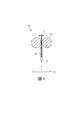
まず、コンポジットから、所望の形状および寸法を有するフィラメントを作成することによって(例えば、押出成型または任意の他の適切なプロセスによって)本開示の導電性ポリマーコンポジットをFDMプロセスに使用してもよい。フィラメントは、3D FDMプリンタにフィラメントを入れ、印刷することができる任意の適切な形状を有していてもよい。最初に供給したときのフィラメントは、その厚みTよりかなり長い連続的な長さを有していてもよく(図1)、例えば、厚みに対する長さの比率は、1に対して100より大きく、例えば、1に対して500より大きく、または1に対して1000以上であり、Tは、フィラメントの最も小さな厚み寸法である(例えば、フィラメントが円形の断面を有する場合は直径)。任意の適切な厚みを使用してもよく、厚みは、使用する3Dプリンタに依存して変わるだろう。一例として、厚みは、約0.1mm〜約10mm、例えば、約0.5mm〜約5mm、または約1mm〜約3mmの範囲であってもよい。 The conductive polymer composites of the present disclosure may be used in an FDM process, first by making filaments from the composite with the desired shape and dimensions (eg, by extrusion or any other suitable process). The filament may have any suitable shape that allows the filament to be placed and printed in a 3D FDM printer. The filament when first fed may have a continuous length significantly longer than its thickness T (FIG. 1), for example, the ratio of length to thickness is greater than 1 to 100. For example, greater than 500 relative to 1 or greater than or equal to 1000 relative to 1, where T is the smallest thickness dimension of the filament (eg, diameter if the filament has a circular cross section). Any suitable thickness may be used, and the thickness will vary depending on the 3D printer used. As an example, the thickness may range from about 0.1 mm to about 10 mm, for example, from about 0.5 mm to about 5 mm, or from about 1 mm to about 3 mm.
本開示のフィラメントを使用する三次元プリンタ100の一例を図1に示す。三次元プリンタ100は、フィラメント104を液化部106に供給するためのフィーダー機構102を備えている。液化部106は、フィラメント104を溶融し、得られた溶融プラスチックを、ノズル108を介して押出成型し、構築プラットフォーム110の上に堆積させる。フィーダー機構102は、フィラメント104を供給することができるローラーまたは任意の他の適切な機構、例えば、フィラメントのスプール(図示せず)を備えていてもよい。液化部106は、フィラメントを加熱するための任意の技術、例えば、加熱要素、レーザーなどを使用してもよい。図1に示される三次元プリンタ100は、単なる例であり、任意の種類の三次元プリンタを使用し、本開示のフィラメントを堆積させてもよい。
An example of a three-
以下の実施例に関し、無電解メッキ、溶融混合およびフィラメントの押出成型の条件は最適化されなかったことを注記しておく。従って、さらに最適化すると、ここに示したものよりも高い導電率が測定されることもあるだろう。 It should be noted that the conditions for electroless plating, melt mixing and extrusion of filaments were not optimized for the following examples. Therefore, with further optimization, higher conductivity may be measured than those shown here.
実施例1
各溶液(〜300mL)を別個の500mLの使い捨て容器に調製した。空気−プラズマ処理または濃硝酸中の環流を行い、MWCNTの表面を酸化した(5.5g)。酸化したMWCNTを増感溶液に加え(30分間)(0.1M SnCl2、0.1M HCl(aq))、次いで、活性化溶液に加え(30分間)(DI水中、0.0014 PdCl2、0.25M HCl)、最後に、無電解メッキ溶液に加えた(10分間)(0.059M AgNO3、4.5mL NH4OHconc、9mLの37%ホルムアルデヒド溶液)。MWCNTを加える直前に、このメッキ溶液にホルムアルデヒドをゆっくりと加えた。それぞれの溶液に浸した後、MWCNTを減圧濾過によって単離し、その後、100mLのDIで洗浄した。得られたメッキされたMWCNTを減圧炉中、70℃で乾燥させた。図2Aは、銀粒子で修飾されたMWCNTのSEM画像を示し、銀粒子は、画像中の明るい点として示す。図2Bは、TEMホルダーの上にある銀粒子(画像中の明るい点)で修飾されたMWCNTのSEM画像を示す。
Example 1
Each solution (~ 300 mL) was prepared in a separate 500 mL disposable container. The surface of the MWCNT was oxidized by air-plasma treatment or recirculation in concentrated nitric acid (5.5 g). Oxidized MWCNT was added to the sensitizing solution (30 minutes) (0.1M SnCl 2 , 0.1M HCl (aq) ) and then added to the activating solution (30 minutes) (DI water, 0.0014 PdCl 2 , 0.0014 PdCl 2 , 0.25M HCl), finally, was added to the electroless plating solution (10 min) (0.059M AgNO 3, 4.5mL NH 4 OH conc, 37% formaldehyde solution 9 mL). Formaldehyde was slowly added to this plating solution just before the addition of MWCNT. After soaking in each solution, MWCNTs were isolated by vacuum filtration and then washed with 100 mL DI. The obtained plated MWCNT was dried in a reduced pressure furnace at 70 ° C. FIG. 2A shows an SEM image of the MWCNT modified with silver particles, which are shown as bright spots in the image. FIG. 2B shows an SEM image of a MWCNT modified with silver particles (bright spots in the image) on a TEM holder.
図2Cは、銀粒子(図2Bの円の半径から)で修飾されたMWCNTのエネルギー分散分光法(EDS)スペクトルを示す。銀のピークは、2.5keV付近にあらわれる。EDSスペクトル中のCl、O、Cu、NaおよびSのピークは、メッキされたMWCNTが取り付けられているTEMホルダーからのバックグラウンドシグナルである。 FIG. 2C shows an energy dispersive spectroscopy (EDS) spectrum of MWCNTs modified with silver particles (from the radius of the circle in FIG. 2B). The silver peak appears near 2.5 keV. The peaks of Cl, O, Cu, Na and S in the EDS spectrum are background signals from the TEM holder fitted with the plated MWCNT.
実施例2−銀でコーティングされたMWCNTコンポジットの調製
ツインスクリューHaake Rheocordミキサーを用い、溶融混合によって導電性ポリマーコンポジットを調製した。Haake中、ポリマーベース(ポリカプロラクトン(PCL))を、銀メッキされたMWCNTと70℃で30分間、30rpmで混合した。
Example 2-Preparation of Silver-Coated MWCNT Composite A conductive polymer composite was prepared by melt mixing using a twin screw Haake Rheocord mixer. In Hake, the polymer base (polycaprolactone (PCL)) was mixed with silver-plated MWCNT at 70 ° C. for 30 minutes at 30 rpm.
PCLコンポジット材料中の得られたAgメッキされたMWCNTを低温粉砕し、改変されたダイ(直径=1.8mm)および16.96kgのおもりを取り付けたTinius Olson Melt Flow Indexer(MFI)を用い、100℃および150℃でそれぞれさらに処理し、フィラメント(d=1.75mm)にした。 The obtained Ag-plated MWCNT in the PCL composite material was cold milled and used with a modified die (diameter = 1.8 mm) and a Tinius Olson Melt Flow Indexer (MFI) fitted with a 16.96 kg weight, 100. Further treatment was performed at ° C. and 150 ° C. to obtain filaments (d = 1.75 mm).
実施例3
実施例2のフィラメントを10cm片に切断し、銀塗料(SPI supplies)を末端に塗った。この銀塗料を使用し、サンプルと、抵抗装置のクランプとの間の良好な接続を確実にした。2点プローブによる抵抗装置を使用し、体積抵抗を測定した。上の式1を用い、体積抵抗をバルク導電率に変換した。結果を以下の表1に示す。
Example 3
The filament of Example 2 was cut into 10 cm pieces and silver paint (SPI suplies) was applied to the ends. This silver paint was used to ensure a good connection between the sample and the clamp of the resistor. Volumetric resistance was measured using a resistor with a two-point probe. Volumetric resistance was converted to bulk conductivity using Equation 1 above. The results are shown in Table 1 below.
実施例4
実施例2および3と同様のコンポジットフィラメントを製造したが、但し、10重量%の銀メッキされたMWCNTに加え、10重量%の銀フレークが含まれていた。PCL中のAgメッキされたMWCNT+銀フレークのバルク導電率を、実施例3に記載したのと同様に決定した。結果を表1に示す。
Example 4
The same composite filaments as in Examples 2 and 3 were produced, except that they contained 10% by weight of silver flakes in addition to 10% by weight of silver-plated MWCNT. The bulk conductivity of the Ag-plated MWCNT + silver flakes in the PCL was determined in the same manner as described in Example 3. The results are shown in Table 1.
図3Aおよび図3Bは、(a)実施例3からのPCL中の10wt%のAgメッキされたMWCNT(図3A)および(b)実施例4からのPCL中の10wt%のAgメッキされたMWCNT+10重量%のAgフレーク(図3B)を含むコンポジットフィラメントの断面のSEM画像を示す。図3Aは、分散した銀と、AgメッキされたCNTの凝集した塊を示す。図3Bは、分散したAgフレークと、AgメッキされたCNTの分布した凝集物を示す。 3A and 3B show (a) 10 wt% Ag-plated MWCNT in PCL from Example 3 (FIG. 3A) and (b) 10 wt% Ag-plated MWCNT +10 in PCL from Example 4. An SEM image of a cross section of a composite filament containing% by weight of Ag flakes (FIG. 3B) is shown. FIG. 3A shows dispersed silver and agglomerated masses of Ag-plated CNTs. FIG. 3B shows dispersed Ag flakes and distributed aggregates of Ag-plated CNTs.
比較例A
実施例2および実施例3と同様のコンポジットフィラメントを製造したが、但し、金属メッキされたCNTを、金属でメッキされていない10重量%のMWCNTと置き換えた。実施例3に記載したのと同様にバルク導電率を決定し、結果を表1に示す。
Comparative Example A
The same composite filaments as in Examples 2 and 3 were produced, except that the metal plated CNTs were replaced with 10 wt% MWCNTs not metal plated. The bulk conductivity was determined in the same manner as described in Example 3, and the results are shown in Table 1.
比較例B
実施例2および実施例3と同様のコンポジットフィラメントを製造したが、但し、10重量%のMWCNTは、金属でメッキされておらず、30%の銀ナノ粒子が熱可塑性ポリマー中に含まれていた。実施例3に記載したのと同様にバルク導電率を決定し、結果を表1に示す。
Comparative Example B
Composite filaments similar to those of Example 2 and Example 3 were produced, except that 10% by weight of MWCNT was not metal plated and 30% of silver nanoparticles were contained in the thermoplastic polymer. .. The bulk conductivity was determined in the same manner as described in Example 3, and the results are shown in Table 1.
比較例C
実施例2および実施例3と同様のコンポジットフィラメントを製造したが、但し、MWCNTを、65重量%のAgフレークと置き換えた。実施例3に記載したのと同様にバルク導電率を決定し、結果を表1に示す。
Comparative Example C
Composite filaments similar to those of Example 2 and Example 3 were produced, provided that MWCNT was replaced with 65% by weight Ag flakes. The bulk conductivity was determined in the same manner as described in Example 3, and the results are shown in Table 1.
比較例D
実施例2および実施例3と同様のコンポジットフィラメントを製造したが、但し、MWCNTを、39重量%のAgナノ粒子と置き換えた。実施例3に記載したのと同様にバルク導電率を決定し、結果を表1に示す。
Comparative Example D
Composite filaments similar to those of Example 2 and Example 3 were produced, provided that the MWCNT was replaced with 39% by weight of Ag nanoparticles. The bulk conductivity was determined in the same manner as described in Example 3, and the results are shown in Table 1.
表1のバルク導電率の測定によって示されるように、(i)10wt%のMWCNTを含むPCL(0.55S/cm)と(ii)銀(Ag)でメッキされた10wt%のMWCNTを含むPCL(0.65S/cm)の間で、導電率の約15%の増加が観察された。10重量%のMWCNTおよび30%の銀ナノ粒子(AgNP)をPCL中で合わせることによって作られた同様のコンポジット材料からは、かなり低い導電率(0.07S/cm)が得られ、MWCNTへの銀の直接的なメッキが導電率を高めると考えられる。MWCNTに直接メッキされたAgは、接触抵抗を減らし、芳香族環のπを積み重ね、中に入り込む網目構造を作成するためにMWCNTが近くに整列する必要性を低減すると考えられ、メッキされた金属によって、金属の接触点を与えることによって、CNTをもっとランダムに配置することができる。PCL中の39wt%のAgNPは、導電率について、0S/cmを測定することを注記しておく。比較例Bの銀ナノ粒子は、実際に、比較例Aの銀ナノチューブを含まないMWNTと比較して、導電率が低いことも注記しておく。この結果は、予想されないものであった。なぜこの現象が起こるのか明らかではないが、可能な説明の1つは、Agナノ粒子の存在によってMWNTがさらに凝集し、望ましい中に入り込む網目構造を形成しなかったということである。 As shown by the bulk conductivity measurements in Table 1, (i) PCL containing 10 wt% MWCNT (0.55 S / cm) and (ii) PCL containing 10 wt% silver (Ag) plated MWCNT. Between (0.65 S / cm), an increase in conductivity of about 15% was observed. A similar composite material made by combining 10% by weight MWCNT and 30% silver nanoparticles (AgNP) in PCL yields fairly low conductivity (0.07S / cm) to MWCNT. Direct plating of silver is thought to increase conductivity. Ag directly plated on MWCNTs is thought to reduce contact resistance, stack π of aromatic rings, and reduce the need for MWCNTs to align close together to create a network structure that penetrates into the plated metal. Allows the CNTs to be placed more randomly by providing metal contact points. It should be noted that 39 wt% AgNP in PCL measures 0 S / cm for conductivity. It should also be noted that the silver nanoparticles of Comparative Example B actually have lower conductivity than the MWNTs of Comparative Example A that do not contain silver nanotubes. This result was unexpected. It is not clear why this phenomenon occurs, but one possible explanation is that the presence of Ag nanoparticles further aggregated the MWNTs and did not form a network structure that penetrated into the desired interior.
(i)PCL中の銀(Ag)でメッキされた10wt%のMWCNT(0.65S/cm)と、(ii)PCL中の銀(Ag)でメッキされた10wt%のMWCNT+10wt%のAgフレーク(2〜5μm)の間で、導電率のさらなる20%の増加が観察され、一方、PCL中の65%(2〜5μm)のAgフレークのみの場合、0S/cmが測定された。 (I) 10 wt% MWCNT (0.65 S / cm) plated with silver (Ag) in PCL and (ii) 10 wt% MWCNT + 10 wt% Ag flakes plated with silver (Ag) in PCL (ii) A further 20% increase in conductivity was observed between 2-5 μm), while 0 S / cm was measured for only 65% (2-5 μm) Ag flakes in PCL.

実施例5−材料の印刷
フィラメントを、Makerbot FDM 3Dプリンタを用いて印刷し、印刷された角材を作成した。印刷された角材(75mm×9mm×3mm)を用い、材料の曲げ弾性率を決定した。表2は、それぞれのポリマーコンポジットフィラメントを印刷するために用いられる印刷パラメータを記載する。
Example 5-Printing of Materials Filaments were printed using a Makerbot FDM 3D printer to create printed square timbers. The flexural modulus of the material was determined using the printed square timber (75 mm × 9 mm × 3 mm). Table 2 lists the printing parameters used to print each polymer composite filament.
表3には、上の実施例に記載される一連のPCL中のフィラメントの機械特性をまとめている。比較のために、添加剤を含まないPCLフィラメントを、上の実施例3のフィラメントと同じ寸法で製造した。ヤング弾性率と曲げ弾性率は、両方とも、コンポジット材料が、ベースポリマー材料PCLと比較して、CNTを加えたにもかかわらず、非常によく似た曲げ性を維持していることを示している。ASTM D638の方法を使用し、材料のヤング弾性率を決定した。ASTM D790のPlastic Flexural 3 Point Bend Testを使用し、材料の曲げ弾性率を決定した。
Table 3 summarizes the mechanical properties of the filaments in the series of PCLs described in the above examples. For comparison, additive-free PCL filaments were made to the same dimensions as the filaments of Example 3 above. Both Young modulus and flexural modulus indicate that the composite material maintains very similar bendability compared to the base polymer material PCL, despite the addition of CNTs. There is. The Young Elastic Modulus of the material was determined using the method of ASTM D638. The Flexural Modulus of the material was determined using the
本開示の広い範囲に記載する数値範囲およびパラメータは概算値であるが、具体例に記載する数値は、可能な限り正確に報告される。しかしながら、任意の数値は、それぞれの試験測定で見出される標準偏差から必然的に得られる特定の誤差を本質的に含む。さらに、本明細書に開示するすべての範囲は、その範囲に包含される任意の部分範囲およびあらゆる部分範囲を包含することが理解されるべきである。 The numerical ranges and parameters described in the broad scope of the present disclosure are approximate values, but the numerical values described in the specific examples are reported as accurately as possible. However, any numerical value essentially contains a particular error that is inevitably obtained from the standard deviation found in each test measurement. Moreover, it should be understood that all scopes disclosed herein include any subrange and any subrange contained within that scope.
本教示を1つ以上の実施の観点で示してきたが、添付の特許請求の範囲の精神および範囲から逸脱することなく、示されている実施例に対し、変更および/または改変を行ってもよい。それに加え、本教示の具体的な特徴が、いくつかの実施例の1つのみに関して開示されていてもよいが、このような特徴を、所望なように、任意の所与の機能または具体的な機能に有利な他の実施例の1つ以上の他の特徴と組み合わせてもよい。さらに、「〜を含む(including)」、「含む(includes)」、「〜を有する(having)」、「有する(has)」、「伴う(with)」という用語またはこれらの変形語をいずれかの詳細な記載および特許請求の範囲に使用する程度まで、このような用語は、「〜を含む(comprising)」という語句と同様の様式で包括的であることを意図している。さらに、本明細書の記載および特許請求の範囲では、「約」という語句は、変更によって、示されている実施形態に対するプロセスまたは構造と不整合がない限り、列挙した値をある程度変えてもよいことを示す。最終的に、「例示的な」は、理想的であると暗示されているのではなく、その記載が実施例として使用されることを示す。 Although the teachings have been presented in terms of one or more practices, modifications and / or modifications to the embodiments shown may be made without departing from the spirit and scope of the appended claims. Good. In addition, the specific features of this teaching may be disclosed with respect to only one of several embodiments, but such features may be, as desired, any given function or specific. It may be combined with one or more other features of other embodiments that favor the function. In addition, any of the terms "inclusion", "inclusions", "having", "has", "with" or variants thereof. To the extent that it is used in detail and in the claims, such terms are intended to be comprehensive in a manner similar to the phrase "comprising". Further, within the description and claims of the present specification, the phrase "about" may change some of the listed values as long as the changes do not inconsistent with the process or structure for the embodiments shown. Show that. Finally, "exemplary" is not implied to be ideal, but indicates that the description is used as an example.
Claims (20)
ポリベンズイミダゾール、ポリ(エチレン−コ−酢酸ビニル)、ポリ(スチレンイソプレンスチレン)、ポリ(スチレンエチレンブチレンスチレン)(SEBS)、ポリ乳酸(PLA)、及びポリカプロラクトンからなる群から選択される少なくとも1つのポリマーを含む熱可塑性ポリマーと;
複数の金属メッキされたカーボンナノチューブであって、導電性ポリマーコンポジットの合計重量を基準として、1重量%〜50重量%の範囲の量である金属メッキされたカーボンナノチューブと;
銀を含む複数の導電性金属フレークであって、導電性ポリマーコンポジットの合計重量を基準として、1重量%〜50重量%の範囲の量である導電性金属フレークと:
を含み、
前記熱可塑性ポリマー、前記複数の金属メッキされたカーボンナノチューブ及び前記複数の導電性金属フレークは混合されて混合物を形成し、
前記導電性ポリマーコンポジットは、金属メッキされていないカーボンナノチューブを使用して作成された同じコンポジットより導電率の増加を示し、導電性ポリマーコンポジットは、0.6S/cmから0.8S/cmのバルク導電率を有し、前記導電率は、前記コンポジットから作られる押出成型されたフィラメントであって、銀が塗布されたチップを有し、10cmの長さ(L)及び1.75mmの直径を有するフィラメントの測定された抵抗(R)に基づいて、式α=L/(R*A)を使用して計算される、導電性ポリマーコンポジット。 It is a conductive polymer composite
At least one selected from the group consisting of polybenzimidazole, poly (ethylene-co-vinyl acetate), poly (styrene isoprene styrene), poly (styrene ethylene butylene styrene) (SEBS), polylactic acid (PLA), and polycaprolactone. With thermoplastic polymers containing one polymer;
Multiple metal-plated carbon nanotubes with metal-plated carbon nanotubes in an amount in the range of 1 % to 50% by weight based on the total weight of the conductive polymer composite;
Multiple conductive metal flakes containing silver, with an amount in the range of 1 % to 50% by weight based on the total weight of the conductive polymer composites:
Including
The thermoplastic polymer, the plurality of metal-plated carbon nanotubes, and the plurality of conductive metal flakes are mixed to form a mixture.
The conductive polymer composite showed an increase in conductivity over the same composite made using non-metal plated carbon nanotubes, with conductive polymer composites ranging from 0.6 S / cm to 0.8 S / cm. It has bulk conductivity, said conductivity is an extrusion-molded filament made from said composite, having a silver-coated chip, 10 cm long (L) and 1.75 mm in diameter. A conductive polymer composite calculated using the formula α = L / (R * A) based on the measured resistance (R) of the filament having.
ポリベンズイミダゾール、ポリ(エチレン−コ−酢酸ビニル)、ポリ(スチレンイソプレンスチレン)、ポリ(スチレンエチレンブチレンスチレン)(SEBS)、ポリ乳酸(PLA)、及びポリカプロラクトンからなる群から選択される少なくとも1つのポリマーを含む熱可塑性ポリマーと;
複数の金属メッキされたカーボンナノチューブであって、導電性ポリマーコンポジットフィラメントの合計重量を基準として、5重量%〜50重量%の範囲の量である複数の金属メッキされたカーボンナノチューブと;
銀を含む複数の導電性金属フレークであって、導電性ポリマーコンポジットフィラメントの合計重量を基準として、5重量%〜50重量%の範囲の量である導電性金属フレークと:
を含み、
前記熱可塑性ポリマー、前記複数の金属メッキされたカーボンナノチューブ及び前記複数の導電性金属フレークは混合されて混合物を形成し、
前記導電性ポリマーコンポジットフィラメントは、金属メッキされていないカーボンナノチューブを使用して作成された同じコンポジットフィラメントより導電率の増加を示し、導電性ポリマーコンポジットフィラメントは、0.6S/cmから0.8S/cmのバルク導電率を有し、前記導電率は、銀が塗布されたチップを有し、10cmの長さ(L)及び1.75mmの直径を有するフィラメントの測定された抵抗(R)に基づいて、式α=L/(R*A)を使用して計算される、導電性ポリマーコンポジットフィラメント。 Conductive polymer composite filament
At least one selected from the group consisting of polybenzimidazole, poly (ethylene-co-vinyl acetate), poly (styrene isoprene styrene), poly (styrene ethylene butylene styrene) (SEBS), polylactic acid (PLA), and polycaprolactone. With thermoplastic polymers containing one polymer;
Multiple metal-plated carbon nanotubes with a plurality of metal-plated carbon nanotubes in an amount in the range of 5% to 50% by weight based on the total weight of the conductive polymer composite filaments ;
A plurality of conductive metal flakes comprising silver, based on the total weight of the conductive polymer Composite preparative filaments, 5 wt% conductive metal flakes in an amount of 50 wt% in the range:
Including
The thermoplastic polymer, the plurality of metal-plated carbon nanotubes, and the plurality of conductive metal flakes are mixed to form a mixture.
The conductive polymer composite filaments show an increase in conductivity over the same composite filaments made using non-metal plated carbon nanotubes, with conductive polymer composite filaments ranging from 0.6 S / cm to 0.8 S. It has a bulk conductivity of / cm, said conductivity to the measured resistance (R) of a filament having a silver- coated chip and having a length (L) of 10 cm and a diameter of 1.75 mm. Based on this, a conductive polymer composite filament calculated using the formula α = L / (R * A).
三次元プリンタに、導電性ポリマーコンポジットを提供することであって、前記導電性ポリマーコンポジットは、熱可塑性ポリマーと、複数の金属メッキされたカーボンナノチューブと、複数の導電性金属フレークとを含み、前記熱可塑性ポリマーはポリベンズイミダゾール、ポリ(エチレン−コ−酢酸ビニル)、ポリ(スチレンイソプレンスチレン)、ポリ(スチレンエチレンブチレンスチレン)(SEBS)、ポリ乳酸(PLA)、及びポリカプロラクトンからなる群から選択される少なくとも1つのポリマーを含み、前記熱可塑性ポリマー、前記金属メッキされたカーボンナノチューブ、前記複数の導電性金属フレークが混合されて混合物を形成する、導電性ポリマーコンポジットを提供することと;
前記導電性ポリマーコンポジットを加熱することと;
加熱したコンポジットを基材の上に押出成型し、三次元物体を作成することと
を含み、
前記導電性ポリマーコンポジットは、金属メッキされていないカーボンナノチューブを使用して作成された同じコンポジットより導電率の増加を示し、前記導電性ポリマーコンポジットは、0.6S/cmから0.8S/cmのバルク導電率を有し、前記導電率は、前記導電性ポリマーコンポジットから作られる押出成型フィラメントであって、銀が塗布された先端を有し、10cmの長さ(L)及び1.75mmの直径を有するフィラメントの測定された抵抗(R)に基づいて、式α=L/(R*A)を使用して計算され、
前記複数の金属メッキされたカーボンナノチューブは、導電性ポリマーコンポジットの合計重量に基づいて、5重量%〜50重量%の範囲の量である金属メッキされたカーボンナノチューブと;
前記複数の導電性金属フレークは銀を含み、導電性ポリマーコンポジットの合計重量に基づいて、5重量%〜50重量%の範囲の量である、方法。 It is a method of three-dimensional printing, and this method is
To provide a three-dimensional printer with a conductive polymer composite, said conductive polymer composite comprising a thermoplastic polymer, a plurality of metal-plated carbon nanotubes, and a plurality of conductive metal flakes. The thermoplastic polymer is selected from the group consisting of polybenzimidazole, poly (ethylene-co-vinyl acetate), poly (styreneisoprenestyrene), poly (styreneethylenebutylenestyrene) (SEBS), polylactic acid (PLA), and polycaprolactone. To provide a conductive polymer composite comprising at least one polymer to be formed, wherein the thermoplastic polymer, the metal-plated carbon nanotube, and the plurality of conductive metal flakes are mixed to form a mixture;
By heating the conductive polymer composite;
Including extruding a heated composite onto a substrate to create a three-dimensional object,
The conductive polymer composite exhibits increased conductivity over the same composite made using non-metal plated carbon nanotubes, the conductive polymer composite from 0.6 S / cm to 0.8 S / cm. The conductivity is an extrusion-molded filament made from the conductive polymer composite, having a silver-coated tip, 10 cm long (L) and 1.75 mm long. Calculated using the formula α = L / (R * A) based on the measured resistance (R) of the filament with diameter.
The plurality of metal-plated carbon nanotubes are with metal-plated carbon nanotubes in an amount in the range of 5% to 50% by weight based on the total weight of the conductive polymer composite;
The method, wherein the plurality of conductive metal flakes contain silver and are in an amount in the range of 5% to 50% by weight based on the total weight of the conductive polymer composite.
Composite heating is in the form of a filament, the method of claim 19.
Applications Claiming Priority (2)
| Application Number | Priority Date | Filing Date | Title |
|---|---|---|---|
| US15/000,609 | 2016-01-19 | ||
| US15/000,609 US10418146B2 (en) | 2016-01-19 | 2016-01-19 | Conductive polymer composite |
Publications (3)
| Publication Number | Publication Date |
|---|---|
| JP2017128719A JP2017128719A (en) | 2017-07-27 |
| JP2017128719A5 JP2017128719A5 (en) | 2020-02-20 |
| JP6789129B2 true JP6789129B2 (en) | 2020-11-25 |
Family
ID=59256230
Family Applications (1)
| Application Number | Title | Priority Date | Filing Date |
|---|---|---|---|
| JP2017002432A Active JP6789129B2 (en) | 2016-01-19 | 2017-01-11 | Conductive polymer composite |
Country Status (4)
| Country | Link |
|---|---|
| US (1) | US10418146B2 (en) |
| JP (1) | JP6789129B2 (en) |
| CA (1) | CA2955235C (en) |
| DE (1) | DE102017200448B4 (en) |
Families Citing this family (19)
| Publication number | Priority date | Publication date | Assignee | Title |
|---|---|---|---|---|
| US10418146B2 (en) | 2016-01-19 | 2019-09-17 | Xerox Corporation | Conductive polymer composite |
| US10186344B2 (en) | 2016-01-19 | 2019-01-22 | Xerox Corporation | Conductive polymer composite |
| US10685763B2 (en) | 2016-01-19 | 2020-06-16 | Xerox Corporation | Conductive polymer composite |
| JP6836101B2 (en) | 2016-01-22 | 2021-02-24 | セイコーエプソン株式会社 | Manufacturing method of 3D model |
| US10796813B2 (en) | 2016-02-16 | 2020-10-06 | Xerox Corporation | Conductive polymer composite |
| US10234342B2 (en) * | 2016-04-04 | 2019-03-19 | Xerox Corporation | 3D printed conductive compositions anticipating or indicating structural compromise |
| DE102017209357A1 (en) | 2017-06-01 | 2018-12-06 | Albis Plastic Gmbh | compound |
| US20190062524A1 (en) * | 2017-08-25 | 2019-02-28 | The Boeing Company | Carbon Nanotube Enhanced Polymers and Methods for Manufacturing the Same |
| CN109694636B (en) * | 2017-10-20 | 2021-11-23 | 常州第六元素材料科技股份有限公司 | Graphene conductive powder coating and preparation method and use method thereof |
| DE102018001222A1 (en) | 2018-02-15 | 2018-09-13 | Bundesrepublik Deutschland, vertr. durch das Bundesministerium der Verteidigung, vertr. durch das Bundesamt für Ausrüstung, Informationstechnik und Nutzung der Bundeswehr | Protected from laser radiation and thermal radiation component made of a plastic |
| US11152131B2 (en) * | 2018-06-20 | 2021-10-19 | The Boeing Company | Conductive compositions of conductive polymer and metal coated fiber |
| US11773271B2 (en) * | 2018-10-19 | 2023-10-03 | University Of South Florida | Conductive paste based on nano-hybrid materials |
| CN111534114A (en) * | 2020-05-15 | 2020-08-14 | 太原理工大学 | Stress sensor preparation method based on SEBS and conductive nano material |
| DE102020128014A1 (en) | 2020-05-20 | 2021-11-25 | Mocom Compounds Gmbh & Co. Kg | Additives and / or additive-additive combinations for compounding, thermoplastic plastic with these and use of the plastic |
| US20240173772A1 (en) * | 2021-03-29 | 2024-05-30 | Olivier Smiljanic | Methods and materials for additive manufacturing |
| WO2023122569A1 (en) * | 2021-12-24 | 2023-06-29 | Essentium Ipco, Llc | System and method of additive manufacturing for enhanced conductivity |
| CN114656657B (en) * | 2022-04-06 | 2024-01-30 | 合肥工业大学 | Preparation method of high-conductivity self-healing nano composite organic hydrogel |
| CN114702752B (en) * | 2022-04-07 | 2022-11-18 | 中山市华洋塑胶颜料有限公司 | Graphene composite plastic for heat dissipation and preparation method thereof |
| CN116003907B (en) * | 2022-12-21 | 2024-08-09 | 武汉金发科技有限公司 | Polypropylene composite material and preparation method thereof |
Family Cites Families (35)
| Publication number | Priority date | Publication date | Assignee | Title |
|---|---|---|---|---|
| DE3005849A1 (en) | 1980-02-16 | 1981-09-03 | Bayer Ag, 5090 Leverkusen | ELECTRICALLY CONDUCTIVE AND ANTISTATIC MOLDS |
| JP2799431B2 (en) | 1996-05-15 | 1998-09-17 | 広島大学長 | Sacrificial specimen for fatigue damage prediction monitoring of structures |
| US8999200B2 (en) * | 2002-07-23 | 2015-04-07 | Sabic Global Technologies B.V. | Conductive thermoplastic composites and methods of making |
| JP2006120665A (en) * | 2004-10-19 | 2006-05-11 | Sumitomo Metal Mining Co Ltd | Conductive resin paste composition containing silver and carbon nano tube, and semiconductor device using the same |
| JP2007138026A (en) * | 2005-11-18 | 2007-06-07 | Bridgestone Corp | Conductive resin composition and conductive resin material |
| WO2008048705A2 (en) | 2006-03-10 | 2008-04-24 | Goodrich Corporation | Low density lightning strike protection for use in airplanes |
| US20080166563A1 (en) | 2007-01-04 | 2008-07-10 | Goodrich Corporation | Electrothermal heater made from thermally conducting electrically insulating polymer material |
| TWI405801B (en) | 2007-10-19 | 2013-08-21 | Nat Univ Tsing Hua | Method of preparation of a mwcnt/polymer composite having electromagnetic interference shielding effectiveness |
| CN101977963B (en) * | 2008-03-28 | 2013-03-27 | 三菱化学株式会社 | Production method of aliphatic polyester |
| US7925454B1 (en) | 2008-08-20 | 2011-04-12 | Florida Turbine Technologies, Inc. | Process for determining a remaining life of a deteriorated turbine component |
| CN104194454B (en) * | 2009-02-16 | 2019-01-08 | 塞特克技术公司 | For the lightning stroke of same with thermosetting compound material and the co-curing conductivity meter facial mask of electromagnetic interference shield |
| WO2010101810A1 (en) | 2009-03-03 | 2010-09-10 | Arkema France | Thermoformable photovoltaic backsheet |
| US20120247808A1 (en) * | 2009-06-22 | 2012-10-04 | Si-Ty Lam | Transparent conductive material |
| US8344053B2 (en) * | 2009-09-10 | 2013-01-01 | Pixelligent Technologies, Llc | Highly conductive composites |
| FR2959231B1 (en) | 2010-04-22 | 2012-04-20 | Arkema France | THERMOPLASTIC AND / OR ELASTOMERIC COMPOSITE MATERIAL BASED ON CARBON NANOTUBES AND GRAPHICS |
| US20120024780A1 (en) * | 2010-06-21 | 2012-02-02 | Herman Carr | Water treatment plant for combined biomass and biogas production |
| EP2489442A1 (en) | 2011-02-18 | 2012-08-22 | Aernnova Engineering Solutions Iberica | Integrated phased array transducer, system and methodology for structural health monitoring of aerospace structures |
| US20140029640A1 (en) * | 2011-04-08 | 2014-01-30 | Mitsubishi Electric Corporation | Solid-state laser device |
| JP6122033B2 (en) | 2012-02-01 | 2017-04-26 | コーニンクレッカ フィリップス エヌ ヴェKoninklijke Philips N.V. | Nanoparticle RF shield used in MRI equipment |
| CN104302707B (en) | 2012-05-15 | 2018-08-28 | 日本瑞翁株式会社 | Conductive composition |
| US8865604B2 (en) | 2012-09-17 | 2014-10-21 | The Boeing Company | Bulk carbon nanotube and metallic composites and method of fabricating |
| CN105408095A (en) * | 2013-06-24 | 2016-03-16 | 哈佛学院院长等 | Printed three-dimensional (3D) functional part and method of making |
| CN104412331A (en) * | 2013-07-02 | 2015-03-11 | 株式会社俞旻St | Composition for oil leak detection and sensor for oil leak detection having same applied thereto |
| JP6563953B2 (en) * | 2013-12-26 | 2019-08-28 | テキサス・テック・ユニバーシティー・システム | Local heating of CNT-filled polymer composites by microwave induction to enhance internal bead diffusion bonding of shaped articles by hot melt filament manufacturing method |
| US10727537B2 (en) | 2014-09-02 | 2020-07-28 | G6 Materials Corp. | Electrochemical devices comprising nanoscopic carbon materials made by additive manufacturing |
| WO2016057250A1 (en) | 2014-10-05 | 2016-04-14 | Leonid Grigorian | 3d printers and feedstocks for 3d printers |
| CN107429398A (en) * | 2014-12-22 | 2017-12-01 | 斯马特高科技有限公司 | Multiple functionalized CNT |
| EP3067678B1 (en) | 2015-03-12 | 2019-10-09 | STBL Medical Research AG | Method for producing a strain gauge device |
| US10284957B2 (en) * | 2015-07-22 | 2019-05-07 | Google Llc | Devices and methods for a high performance electromagnetic speaker based on monolayers |
| US11097440B2 (en) | 2015-11-05 | 2021-08-24 | United States Of America As Represented By The Administrator Of Nasa | Cutting mechanism for carbon nanotube yarns, tapes, sheets and polymer composites thereof |
| US10562227B2 (en) | 2015-12-01 | 2020-02-18 | Massachusetts Institute Of Technology | Systems, devices, and methods for high-throughput three-dimensional printing |
| US10685763B2 (en) | 2016-01-19 | 2020-06-16 | Xerox Corporation | Conductive polymer composite |
| US10186344B2 (en) | 2016-01-19 | 2019-01-22 | Xerox Corporation | Conductive polymer composite |
| US10418146B2 (en) | 2016-01-19 | 2019-09-17 | Xerox Corporation | Conductive polymer composite |
| US10234342B2 (en) | 2016-04-04 | 2019-03-19 | Xerox Corporation | 3D printed conductive compositions anticipating or indicating structural compromise |
-
2016
- 2016-01-19 US US15/000,609 patent/US10418146B2/en active Active
-
2017
- 2017-01-11 JP JP2017002432A patent/JP6789129B2/en active Active
- 2017-01-12 DE DE102017200448.7A patent/DE102017200448B4/en active Active
- 2017-01-16 CA CA2955235A patent/CA2955235C/en active Active
Also Published As
| Publication number | Publication date |
|---|---|
| US10418146B2 (en) | 2019-09-17 |
| CA2955235C (en) | 2020-09-15 |
| DE102017200448B4 (en) | 2022-07-14 |
| US20170207001A1 (en) | 2017-07-20 |
| DE102017200448A1 (en) | 2017-07-20 |
| JP2017128719A (en) | 2017-07-27 |
| CA2955235A1 (en) | 2017-07-19 |
Similar Documents
| Publication | Publication Date | Title |
|---|---|---|
| JP6789129B2 (en) | Conductive polymer composite | |
| JP4480368B2 (en) | Resin composition containing nanoscale carbon, conductive or antistatic resin molding, conductive or antistatic resin coating composition, antistatic film, and production method thereof | |
| JP7005145B2 (en) | Conductive polymer composite | |
| US7462656B2 (en) | Electrically conductive compositions and method of manufacture thereof | |
| JP2006526058A (en) | Conductive composition and method for producing the same | |
| KR101082932B1 (en) | method for manufacturing metal coated carbon nano tube and metal coated carbon nano tube manufactured by the method | |
| JP5457274B2 (en) | Highly thermally conductive and moldable thermoplastic composites and compositions | |
| KR20060061306A (en) | Electrically conductive compositions and method of manufacture thereof | |
| JP2017128719A5 (en) | ||
| US10796813B2 (en) | Conductive polymer composite | |
| Oh et al. | Silver-plated carbon nanotubes for silver/conducting polymer composites | |
| WO2012133627A1 (en) | Silver-coated copper powder and method for producing same, silver-coated copper powder-containing conductive paste, conductive adhesive agent, conductive film, and electric circuit | |
| JP2014529352A (en) | Nanotube and finely pulverized carbon fiber polymer composite composition and production method | |
| CN104004355A (en) | Thermoplastic resin composition with EMI shielding properties | |
| JP7129402B2 (en) | Integrally-formed body and composite material, electrical contact terminal and printed wiring board having said integrally-formed body | |
| KR101724064B1 (en) | Conductive carbon nanotube-metal composite ink | |
| KR20140107119A (en) | Thermoplastic Resin Composition Having Excellent EMI Shielding Property | |
| KR20240005054A (en) | Polybutylene terephthalate compositions and articles | |
| JPH02168698A (en) | Conductive resin film and manufacture thereof | |
| KR101733222B1 (en) | Method for manufacturing a conductive polymer composite and a conductive polymer composite manufactured by the same | |
| KR101088723B1 (en) | Conductive paste comprising metal nanoparticle-deposited carbon nanostructure and preparation method thereof | |
| Kennel | . Electrical Properties of Nanoparticle-Filled Polymers | |
| JP2003342474A (en) | Conductive resin material |
Legal Events
| Date | Code | Title | Description |
|---|---|---|---|
| RD02 | Notification of acceptance of power of attorney |
Free format text: JAPANESE INTERMEDIATE CODE: A7422 Effective date: 20170120 |
|
| RD04 | Notification of resignation of power of attorney |
Free format text: JAPANESE INTERMEDIATE CODE: A7424 Effective date: 20170411 |
|
| A521 | Request for written amendment filed |
Free format text: JAPANESE INTERMEDIATE CODE: A523 Effective date: 20200108 |
|
| A621 | Written request for application examination |
Free format text: JAPANESE INTERMEDIATE CODE: A621 Effective date: 20200108 |
|
| A871 | Explanation of circumstances concerning accelerated examination |
Free format text: JAPANESE INTERMEDIATE CODE: A871 Effective date: 20200108 |
|
| A975 | Report on accelerated examination |
Free format text: JAPANESE INTERMEDIATE CODE: A971005 Effective date: 20200115 |
|
| A977 | Report on retrieval |
Free format text: JAPANESE INTERMEDIATE CODE: A971007 Effective date: 20200424 |
|
| A131 | Notification of reasons for refusal |
Free format text: JAPANESE INTERMEDIATE CODE: A131 Effective date: 20200602 |
|
| A521 | Request for written amendment filed |
Free format text: JAPANESE INTERMEDIATE CODE: A523 Effective date: 20200826 |
|
| TRDD | Decision of grant or rejection written | ||
| A01 | Written decision to grant a patent or to grant a registration (utility model) |
Free format text: JAPANESE INTERMEDIATE CODE: A01 Effective date: 20201006 |
|
| A61 | First payment of annual fees (during grant procedure) |
Free format text: JAPANESE INTERMEDIATE CODE: A61 Effective date: 20201102 |
|
| R150 | Certificate of patent or registration of utility model |
Ref document number: 6789129 Country of ref document: JP Free format text: JAPANESE INTERMEDIATE CODE: R150 |
|
| R250 | Receipt of annual fees |
Free format text: JAPANESE INTERMEDIATE CODE: R250 |