JP6788997B2 - 2-axis hinge and terminal equipment using this 2-axis hinge - Google Patents
2-axis hinge and terminal equipment using this 2-axis hinge Download PDFInfo
- Publication number
- JP6788997B2 JP6788997B2 JP2016092830A JP2016092830A JP6788997B2 JP 6788997 B2 JP6788997 B2 JP 6788997B2 JP 2016092830 A JP2016092830 A JP 2016092830A JP 2016092830 A JP2016092830 A JP 2016092830A JP 6788997 B2 JP6788997 B2 JP 6788997B2
- Authority
- JP
- Japan
- Prior art keywords
- hinge shaft
- hinge
- gear
- rotation
- cam
- Prior art date
- Legal status (The legal status is an assumption and is not a legal conclusion. Google has not performed a legal analysis and makes no representation as to the accuracy of the status listed.)
- Active
Links
- 230000001360 synchronised effect Effects 0.000 claims description 20
- 238000003825 pressing Methods 0.000 claims description 6
- 238000003780 insertion Methods 0.000 description 18
- 230000037431 insertion Effects 0.000 description 18
- 241000209094 Oryza Species 0.000 description 6
- 235000007164 Oryza sativa Nutrition 0.000 description 6
- 235000009566 rice Nutrition 0.000 description 6
- 230000000694 effects Effects 0.000 description 2
- 238000004519 manufacturing process Methods 0.000 description 2
- 230000002093 peripheral effect Effects 0.000 description 2
- 229920001690 polydopamine Polymers 0.000 description 2
- 238000013459 approach Methods 0.000 description 1
- 230000006835 compression Effects 0.000 description 1
- 238000007906 compression Methods 0.000 description 1
- 239000000470 constituent Substances 0.000 description 1
- 238000002788 crimping Methods 0.000 description 1
- 238000009434 installation Methods 0.000 description 1
- 238000000034 method Methods 0.000 description 1
- 238000004904 shortening Methods 0.000 description 1
- 229920003002 synthetic resin Polymers 0.000 description 1
- 239000000057 synthetic resin Substances 0.000 description 1
Images


Classifications
-
- E—FIXED CONSTRUCTIONS
- E05—LOCKS; KEYS; WINDOW OR DOOR FITTINGS; SAFES
- E05D—HINGES OR SUSPENSION DEVICES FOR DOORS, WINDOWS OR WINGS
- E05D3/00—Hinges with pins
- E05D3/06—Hinges with pins with two or more pins
- E05D3/12—Hinges with pins with two or more pins with two parallel pins and one arm
- E05D3/122—Gear hinges
-
- F—MECHANICAL ENGINEERING; LIGHTING; HEATING; WEAPONS; BLASTING
- F16—ENGINEERING ELEMENTS AND UNITS; GENERAL MEASURES FOR PRODUCING AND MAINTAINING EFFECTIVE FUNCTIONING OF MACHINES OR INSTALLATIONS; THERMAL INSULATION IN GENERAL
- F16C—SHAFTS; FLEXIBLE SHAFTS; ELEMENTS OR CRANKSHAFT MECHANISMS; ROTARY BODIES OTHER THAN GEARING ELEMENTS; BEARINGS
- F16C11/00—Pivots; Pivotal connections
- F16C11/04—Pivotal connections
-
- G—PHYSICS
- G06—COMPUTING; CALCULATING OR COUNTING
- G06F—ELECTRIC DIGITAL DATA PROCESSING
- G06F1/00—Details not covered by groups G06F3/00 - G06F13/00 and G06F21/00
- G06F1/16—Constructional details or arrangements
- G06F1/1613—Constructional details or arrangements for portable computers
- G06F1/1633—Constructional details or arrangements of portable computers not specific to the type of enclosures covered by groups G06F1/1615 - G06F1/1626
- G06F1/1675—Miscellaneous details related to the relative movement between the different enclosures or enclosure parts
- G06F1/1681—Details related solely to hinges
-
- E—FIXED CONSTRUCTIONS
- E05—LOCKS; KEYS; WINDOW OR DOOR FITTINGS; SAFES
- E05D—HINGES OR SUSPENSION DEVICES FOR DOORS, WINDOWS OR WINGS
- E05D3/00—Hinges with pins
- E05D3/06—Hinges with pins with two or more pins
-
- E—FIXED CONSTRUCTIONS
- E05—LOCKS; KEYS; WINDOW OR DOOR FITTINGS; SAFES
- E05D—HINGES OR SUSPENSION DEVICES FOR DOORS, WINDOWS OR WINGS
- E05D3/00—Hinges with pins
- E05D3/06—Hinges with pins with two or more pins
- E05D3/12—Hinges with pins with two or more pins with two parallel pins and one arm
-
- F—MECHANICAL ENGINEERING; LIGHTING; HEATING; WEAPONS; BLASTING
- F16—ENGINEERING ELEMENTS AND UNITS; GENERAL MEASURES FOR PRODUCING AND MAINTAINING EFFECTIVE FUNCTIONING OF MACHINES OR INSTALLATIONS; THERMAL INSULATION IN GENERAL
- F16C—SHAFTS; FLEXIBLE SHAFTS; ELEMENTS OR CRANKSHAFT MECHANISMS; ROTARY BODIES OTHER THAN GEARING ELEMENTS; BEARINGS
- F16C11/00—Pivots; Pivotal connections
- F16C11/04—Pivotal connections
- F16C11/045—Pivotal connections with at least a pair of arms pivoting relatively to at least one other arm, all arms being mounted on one pin
-
- F—MECHANICAL ENGINEERING; LIGHTING; HEATING; WEAPONS; BLASTING
- F16—ENGINEERING ELEMENTS AND UNITS; GENERAL MEASURES FOR PRODUCING AND MAINTAINING EFFECTIVE FUNCTIONING OF MACHINES OR INSTALLATIONS; THERMAL INSULATION IN GENERAL
- F16C—SHAFTS; FLEXIBLE SHAFTS; ELEMENTS OR CRANKSHAFT MECHANISMS; ROTARY BODIES OTHER THAN GEARING ELEMENTS; BEARINGS
- F16C11/00—Pivots; Pivotal connections
- F16C11/04—Pivotal connections
- F16C11/10—Arrangements for locking
- F16C11/103—Arrangements for locking frictionally clamped
-
- G—PHYSICS
- G06—COMPUTING; CALCULATING OR COUNTING
- G06F—ELECTRIC DIGITAL DATA PROCESSING
- G06F1/00—Details not covered by groups G06F3/00 - G06F13/00 and G06F21/00
- G06F1/16—Constructional details or arrangements
-
- H—ELECTRICITY
- H04—ELECTRIC COMMUNICATION TECHNIQUE
- H04M—TELEPHONIC COMMUNICATION
- H04M1/00—Substation equipment, e.g. for use by subscribers
- H04M1/02—Constructional features of telephone sets
- H04M1/0202—Portable telephone sets, e.g. cordless phones, mobile phones or bar type handsets
-
- H—ELECTRICITY
- H05—ELECTRIC TECHNIQUES NOT OTHERWISE PROVIDED FOR
- H05K—PRINTED CIRCUITS; CASINGS OR CONSTRUCTIONAL DETAILS OF ELECTRIC APPARATUS; MANUFACTURE OF ASSEMBLAGES OF ELECTRICAL COMPONENTS
- H05K5/00—Casings, cabinets or drawers for electric apparatus
- H05K5/02—Details
- H05K5/0217—Mechanical details of casings
- H05K5/0226—Hinges
-
- E—FIXED CONSTRUCTIONS
- E05—LOCKS; KEYS; WINDOW OR DOOR FITTINGS; SAFES
- E05Y—INDEXING SCHEME RELATING TO HINGES OR OTHER SUSPENSION DEVICES FOR DOORS, WINDOWS OR WINGS AND DEVICES FOR MOVING WINGS INTO OPEN OR CLOSED POSITION, CHECKS FOR WINGS AND WING FITTINGS NOT OTHERWISE PROVIDED FOR, CONCERNED WITH THE FUNCTIONING OF THE WING
- E05Y2900/00—Application of doors, windows, wings or fittings thereof
- E05Y2900/60—Application of doors, windows, wings or fittings thereof for other use
- E05Y2900/606—Application of doors, windows, wings or fittings thereof for other use for electronic devices
Description
本発明は、ノートパソコンやモバイルパソコン、PDAなどの端末機器の第1筐体と第2筐体を相対的に開閉する際に用いて好適な2軸ヒンジ及びこの2軸ヒンジを用いた端末機器に関する。 The present invention is a biaxial hinge suitable for opening and closing the first housing and the second housing of a terminal device such as a notebook personal computer, a mobile personal computer, or a PDA, and a terminal device using the biaxial hinge. Regarding.
2軸ヒンジには、第1ヒンジシャフトと第2ヒンジシャフトを互いに交わる方向へ配置した交叉2軸ヒンジと、互いに平行方向へ配置した平行2軸ヒンジとがあるが、本発明は後者の平行2軸ヒンジに属する。 The biaxial hinge includes a crossed biaxial hinge in which the first hinge shaft and the second hinge shaft are arranged in the direction of intersecting each other and a parallel biaxial hinge arranged in the direction parallel to each other. In the present invention, the latter parallel 2 It belongs to the shaft hinge.
この平行2軸ヒンジは、1軸のヒンジに較べて、第1の筐体と第2の筐体を手に持った本を開くように左右均等に開くように構成することができるという利点がある。そのような平行2軸ヒンジとして例えば下記特許文献1に記載されたものが公知である。
Compared to the uniaxial hinge, this parallel biaxial hinge has an advantage that it can be configured to open the book holding the first housing and the second housing evenly on the left and right sides. is there. As such a parallel biaxial hinge, for example, those described in
しかしながら、この特許文献1に記載の2軸ヒンジは、第1筐体と第2筐体を相対的に90°以上開いた場合、第1筐体の後側面に対して第2筐体の後側面が覆い被さるようになりなってしまうことから、第1筐体の後側面に配置されることの多いLANポートやUSBポート等々の各種ポートや電源コネクタや、排熱口等を塞ぎ、それらの各種ポート等に接続されたケーブル類と干渉し、それらの使用に支障を生じさせたり、排熱が思うようにいかず、商品寿命を短くするといった問題があった。
However, the biaxial hinge described in
また、最近はノートパソコンを軽量化かつ薄型化することが望まれており、特許文献1に記載の2軸ヒンジでは、対応が十分にできないという問題があった。
Further, recently, it has been desired to reduce the weight and thickness of a notebook computer, and there is a problem that the biaxial hinge described in
本発明はこれらの問題点を解決するためなされたものであり、その目的とするところは、端末機器の薄型化に対応できると共に、端末機器に接続された各種プラグやケーブル等の使用に障害を生じさせない上に、排熱にも支障を生じさせず、かつ製造コストの安価な2軸ヒンジを提供せんとするにある。 The present invention has been made to solve these problems, and an object of the present invention is to be able to cope with thinning of a terminal device and to impede the use of various plugs, cables, etc. connected to the terminal device. It is an object of the present invention to provide a biaxial hinge which does not generate heat, does not hinder heat exhaust, and has a low manufacturing cost.
上記した目的を達成するために本発明に係る2軸ヒンジは、端末機器の第1筐体に対して第2筐体を開閉可能に連結する2軸ヒンジであって、前記第1筐体へ取り付けられる取付プレート部とこの取付プレート部から上方へ立設した大径部と小径部を有する軸受部から成る取付部材と、この取付部材の前記小径部に回転可能に軸支されると共に、取付プレートを介して前記第2筐体へ取り付けられる外径の細い第1ヒンジシャフトと、前記取付部材の前記大径部に前記第1ヒンジシャフトと平行状態を保ちつつ軸方向へ位置をずらせて回転可能に軸支される前記第1ヒンジシャフトより外径の太い第2ヒンジシャフトと、前記第1ヒンジシャフトと前記第2ヒンジシャフトの間に設けられる一方のヒンジシャフトの回転に同期して他方のヒンジシャフトを互いに異なる方向に回転させる同期回転手段とを有し、前記第1ヒンジシャフトの側には、当該第1ヒンジシャフトの回転時にフリクショントルクを発生させるサブのフリクショントルク発生手段を設け、前記第2ヒンジシャフトの側には、当該第2ヒンジシャフトの回転時に前記第1ヒンジシャフトの側のサブのフリクショントルク発生手段と較べて強いフリクショントルクを発生させるメインのフリクショントルク発生手段と、当該第2ヒンジシャフトをその所定の回転角度から一方向へ回転付勢させて自動的に回転させる吸込み手段とを設け、この吸込み手段による前記第2ヒンジシャフトの回転を、前記同期回転手段を介して前記第1ヒンジシャフトへ伝達させることを特徴とする。 The biaxial hinge according to the present invention in order to achieve the above object is a biaxial hinge that connects the second housing to the first housing of the terminal device so as to be openable and closable, to the first housing. A mounting member consisting of a mounting plate to be mounted, a bearing portion having a large diameter portion and a small diameter portion erected upward from the mounting plate portion, and a mounting member rotatably supported and mounted on the small diameter portion of the mounting member. A first hinge shaft having a small outer diameter attached to the second housing via a plate and a large-diameter portion of the mounting member are rotated by shifting their positions in the axial direction while maintaining a parallel state with the first hinge shaft. and thick second hinge shaft outer diameter than the first hinge shaft is rotatably supported, rotated in the same synchronized with the other of the first hinge shaft and one of the hinge shaft provided between the second hinge shaft It has synchronous rotation means for rotating the hinge shafts in different directions, and a sub friction torque generating means for generating friction torque when the first hinge shaft is rotated is provided on the side of the first hinge shaft. On the side of the second hinge shaft, a main friction torque generating means that generates a stronger friction torque than the sub friction torque generating means on the side of the first hinge shaft when the second hinge shaft rotates, and the first friction torque generating means . A suction means for automatically rotating the two hinge shafts by rotationally urging them in one direction from the predetermined rotation angle is provided, and the rotation of the second hinge shaft by the suction means is performed via the synchronous rotation means. It is characterized in that it is transmitted to the first hinge shaft .
その際に、本発明は、前記同期回転手段を、前記第1ヒンジシャフトに回転を拘束されて取り付けられた第1ギアと、前記第2ヒンジシャフトに回転を拘束されて取り付けられた前記第1ギアより大径の第2ギアと、前記第1ギアと前記第2ギアとの間に設けられ、一方の回転を他方に伝え、それぞれ異なる方向へ回転させる中間ギアと、で構成したことを特徴とする。 At that time, in the present invention, the synchronous rotation means is attached to the first gear whose rotation is constrained to the first hinge shaft and to the first gear which is constrained to rotate to the second hinge shaft. It is characterized by being composed of a second gear having a diameter larger than that of the gear, and an intermediate gear provided between the first gear and the second gear, which transmits one rotation to the other and rotates in different directions. And.
本発明はさらに、前記同期回転手段を、前記第1ヒンジシャフトに回転を拘束されて取り付けられた第1ギアと、前記第2ヒンジシャフトに回転を拘束されて取り付けられ、前記第1ギアと噛み合わせられて前記第1ギアと異なる方向へ回転する前記第1ギアより大径の第2ギアと、で構成したことを特徴とする。 The present invention further engages the synchronous rotation means with the first gear, which is constrained to rotate and attached to the first hinge shaft, and the first gear, which is attached to the second hinge shaft with constrained rotation. It is characterized in that it is composed of a second gear having a diameter larger than that of the first gear, which is combined and rotates in a direction different from that of the first gear.
本発明はさらに、前記メインのフリクショントルク発生手段を、前記第1ヒンジシャフトと前記第2ヒンジシャフトを回転可能に挿通させたフリクションプレートと、前記第2ヒンジシャフト上に回転を拘束された状態で装着され、前記取付部材の前記軸受部の前記大径部と前記フリクションプレートの大径部との間に介在されるフリクションワッシャーと、前記フリクションワッシャーに前記取付部材と前記フリクションプレートを圧接するために前記第2ヒンジシャフト上に設けられた弾性手段と、で構成したことを特徴とする。 Further, in the present invention, the main friction torque generating means is rotatably inserted into the first hinge shaft and the second hinge shaft, and the rotation is restrained on the second hinge shaft. A friction washer that is mounted and interposed between the large-diameter portion of the bearing portion of the mounting member and the large-diameter portion of the friction plate, and for pressing the mounting member and the friction plate against the friction washer. It is characterized in that it is composed of an elastic means provided on the second hinge shaft.
本発明はさらに、前記サブのフリクショントルク発生手段を、前記第1ヒンジシャフトと前記第2ヒンジシャフトを回転可能に挿通させたフリクションプレートと、前記フリクションプレートの小径部の一方の側と前記取付部材の軸受部の小径部との間に前記第1ヒンジシャフトに回転を拘束されて配置された第1ワッシャーと、前記フリクションプレートの小径部の他方の側と前記第1ヒンジシャフトにネジ着させた第1締付ナットとの間に前記第1ヒンジシャフトの回転を拘束させて配置された第2ワッシャーと、で構成したことを特徴とする。 The present invention further comprises a friction plate in which the first hinge shaft and the second hinge shaft are rotatably inserted through the sub-friction torque generating means, one side of a small diameter portion of the friction plate, and the mounting member. A first washer whose rotation was constrained to be arranged by the first hinge shaft between the small diameter portion of the bearing portion and the other side of the small diameter portion of the friction plate and the first hinge shaft were screwed. It is characterized in that it is composed of a second washer arranged so as to restrain the rotation of the first hinge shaft between the first tightening nut and the first hinge shaft.
本発明はさらに、前記吸込み手段を、フリクションプレートに係止させて前記第2ヒンジシャフトを回転可能に挿通させると共に、その一側部外側に略円弧状のカム凹部又はカム凸部を備えたカムプレート部材と、前記第2ヒンジシャフトに回転を拘束されて取り付けられ、前記カムプレート部材の前記カム凹部又はカム凸部と対向する面にカム凸部又はカム凹部を有するカムフォロワー部材と、前記第2ヒンジシャフトに設けられた前記カムプレート部材と前記カムフォロワー部材とを互いに圧接させる弾性手段と、で構成したことを特徴とする。 Further, the present invention further engages the suction means with a friction plate to rotatably insert the second hinge shaft, and further, a cam provided with a substantially arc-shaped cam recess or cam protrusion on the outside of one side thereof. A plate member, a cam follower member which is attached to the second hinge shaft with rotation restrained and has a cam convex portion or a cam concave portion on a surface of the cam plate member facing the cam concave portion or the cam convex portion, and the first. 2 It is characterized in that it is composed of an elastic means for pressing the cam plate member and the cam follower member provided on the hinge shaft with each other.
そして、本発明は、前記いずれかに記載の発明に係る2軸ヒンジを端末機器に用いたことを特徴とする。 The present invention is characterized in that the biaxial hinge according to any one of the above is used for a terminal device.
本発明は上記したように、第2筐体の側に取り付けられる第1ヒンジシャフトの外形及びこの第1ヒンジシャフトに装着される第1ギアやワッシャーなどの部品の外径を、第1筐体側に取り付けられる第2ヒンジシャフト及びこの第2ヒンジシャフト側に装着される第2ギアやフリクションワッシャーなどより小径に構成することによって、第1筐体を薄くすることが可能となり、さらに前記メインのフリクショントルク発生手段や吸込み手段、及びそれらを機能させる弾性手段を第2ヒンジシャフト上にだけ設けることによって必要なフリクショントルクを確保することができるので、第2筐体の開成時に、第1筐体の後側面に設けられた各種ポートに接続された各種プラグやケーブルに対して第2筐体の後側面がぶつかったり、排熱口が塞がれたりして、それらの機能が妨げられることのない、安価で適応性に優れた2軸ヒンジとして好適に用いることができるという作用効果を奏し得るものである。 As described above, in the present invention, the outer shape of the first hinge shaft attached to the side of the second housing and the outer diameter of parts such as the first gear and washers mounted on the first hinge shaft are set on the first housing side. The first housing can be made thinner by making the diameter smaller than that of the second hinge shaft attached to the second hinge shaft and the second gear or friction washer attached to the second hinge shaft side, and further, the main friction. Since the required friction torque can be secured by providing the torque generating means, the suction means, and the elastic means for functioning them only on the second hinge shaft, the first housing is opened when the second housing is opened. The rear side of the second housing will not hit the various plugs and cables connected to the various ports provided on the rear side, and the heat exhaust port will not be blocked, and their functions will not be hindered. It can exert the effect that it can be suitably used as a biaxial hinge which is inexpensive and has excellent adaptability.
そして、本発明はまた、上記の如き本発明に係る2軸ヒンジを用いることにより、薄型で使い勝手の良い端末機器を提供できるものである。 Further, the present invention can also provide a thin and easy-to-use terminal device by using the biaxial hinge according to the present invention as described above.
以下に本発明に係る2軸ヒンジを端末機器の1例であるノートパソコンに用いた場合の実施例について図面に基づいて説明するが、本発明に係る2軸ヒンジを用い得る対象機器はノートパソコンに限定されず、互いに上下方向へ開閉可能に連結される第1筐体と第2筐体を有するモバイルパソコン、PDA等の端末機器、その他のものにも広く用いることができるものである。 Hereinafter, an example in which the biaxial hinge according to the present invention is used for a notebook computer which is an example of a terminal device will be described with reference to the drawings. However, the target device which can use the biaxial hinge according to the present invention is a notebook computer. The present invention is not limited to the above, and can be widely used for mobile personal computers having a first housing and a second housing that are connected to each other so as to be openable and closable, terminal devices such as PDAs, and others.
図1(a)、(b)は、本発明に係る2軸ヒンジを用いた端末機器の1例としてのノートパソコン1を示す。このノートパソコン1は、キーボード部2aを設けた第1筐体2と、ディスプレイ部3aを設けた第2筐体3の各後部の左右個所を、本発明に係る一対の2軸ヒンジ4と5で開閉可能に連結させて成るものである。第1筐体2の右側面には、電源プラグ7を差し込むための電源コネクタ6aが設けられ、後側面には、LANポート6bやUSBポート6c、6d、等々の各種ポートや排熱口が配設されている。
1 (a) and 1 (b) show a
2軸ヒンジ4と5の構成は、両者共に同じ構成であるので、以下その一方の指示記号4のもののみを説明し、他方の指示記号5で示したものの説明は省略する。勿論、動作に支障がない場合には、指示記号5で示した2軸ヒンジの構成を別なものとしても良い。
Since the configurations of the two-axis hinges 4 and 5 are the same, only one of the
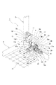
図2〜図11は、本発明に係る2軸ヒンジ4の一実施例を示す。とくに図5、図6に示す如く、第1ヒンジシャフト11は、後述する第2ヒンジシャフト12より小径に形成されている。この第1ヒンジシャフト11は、その一端部側から断面扁平形状を呈し、その表面に取付孔11b、11bを設けた取付板部11aと、この取付板部11aに続いて設けられた第2ヒンジシャフト12に設けられるフランジ部12aよりも小径のフランジ部11cと、このフランジ部11cに続いて設けられた断面略楕円形状を呈した変形軸部11dと、この変形軸部11dの先端近くに設けられた雄ネジ部11eとから構成されている。
2 to 11 show an embodiment of the
図2〜図6に示したように、第1ヒンジシャフト11の取付板部11aには、取付プレート13が取り付けられており、この取付プレート13の取付板部11aへの取付方法は、第1ヒンジシャフト11の2個の取付孔11b、11bと取付プレート13の取付孔13a、13aを通したフランジ部付の取付ピン13d、13dの各端部をかしめることによってなされている。そして、取付プレート13は、当該取付プレート13に設けた取付孔13b、13b及び13cにねじ込まれる取付ネジ13e、13e及び13f(図2)を用いて、ノートパソコン1の第2筐体3の下面側へ取り付けられる構成である。尚、取付ピン13d、13dはこれを取付ネジとしてもよい。この第1ヒンジシャフト11の変形軸部11dには、後述する第2ヒンジシャフト12に装着された第2ギア17よりも小径の第1ギア16がこの変形軸部11dに対して回転不能なように拘束された状態で装着されている。第1ヒンジシャフト11の変形軸部11dは更に、取付部材14の第1軸受孔14c、第1ワッシャー22の変形挿通孔22a、フリクションプレート21の第1軸受孔21a、第2ワッシャー24の変形挿通孔24aに順次挿通され、その先端の雄ネジ部11eに第1締付ナット25がその雌ネジ孔25aによってネジ着される。
As shown in FIGS. 2 to 6, a mounting
次に、同じく図2〜図5に示したように、指示記号12で示したものは、前記第1ヒンジシャフト11に対して上下方向へ平行に配置される第2ヒンジシャフトである。この第2ヒンジシャフト12は、第1ヒンジシャフトに対し大径に構成されており、その一端部に設けられたところの第1ヒンジシャフトのフランジ部11cよりも大径のフランジ部12aと、このフランジ部12aに続いて設けられた断面略楕円形状を呈した変形軸部12bと、この変形軸部12bに続いて設けられた雄ネジ部12cとから構成されている。
Next, as also shown in FIGS. 2 to 5, what is indicated by the
この第2ヒンジシャフト12の変形軸部12bには、第1ギア16よりも大径の第2ギア17がこの変形軸部12bに対して回転不能なように拘束された状態で装着され、更に前記取付部材14が回転可能なように装着される。この取付部材14には取付プレート部14aが一体的に設けられ、当該取付プレート部14aは、当該取付プレート部14aに設けた取付孔14h、14hにねじ込まれる取付ネジ14i、14i(図2)を用いて、ノートパソコン1の第1筐体2の上面側へ取り付けられる構成となっている。
A
前記取付部材14は、前記第1ヒンジシャフト11と第2ヒンジシャフト12とを、互いに平行状態で上下方向に配置させて回転可能に保持するように構成されている。即ち、取付部材14は、前記取付プレート部14aより上方に設けた軸受部14bの小径部14jと大径部14kに上下方向に位置して互いに平行に設けた第1軸受孔14cと第2軸受孔14dを有し、この各第1軸受孔14cと第2軸受孔14dに、前記第1ヒンジシャフト11の一端部側に位置する変形軸部11dと第2ヒンジシャフト12の他端部側に位置する変形軸部12bをそれぞれ回転可能に挿通させて成るものである。また、第1ヒンジシャフト11と第2ヒンジシャフト12は、平行状態であるが、その取付部材14の軸受部14bに対する装着部分が互いに軸方向へずれている。この構成が、第1ヒンジシャフト11自体とこの第1ヒンジシャフト11へ取り付けられる部材の外径を第2ヒンジシャフトの側のものよりも小径とし、かつ、第1ヒンジシャフト11側に設けた大きなフリクショントルクを創出しないサブのフリクショントルク発生手段の簡略な構成と相まって、この第1ヒンジシャフト11を取り付ける第2筐体3の厚さを減じさせる効果を奏するようにすることができるものである。また、この取付部材14は、後述する第1ギア16、第2ギア17及び中間ギア18を互いに噛合状態で保持するギアサポート部材を兼ねる構成となっている。
The mounting
次に、2軸ヒンジ4の第2ヒンジシャフト12に設けられた回転制御手段19について順次説明する。この回転制御手段19は、同期回転手段15、フリクショントルク発生手段20、吸込み手段26から構成される。尚、フリクショントルク発生手段20と吸込み手段26は、両者で兼用する弾性手段29を有する。まず、同期回転手段15について説明する。この同期回転手段15は、とくに図3〜図5に示したように、第1ヒンジシャフト11の変形軸部11dに、その中心部軸方向に設けた変形挿通孔16aを挿通係合させた傘歯車から成る第1ギア16と、第2ヒンジシャフト12の変形軸部12bにその中心部軸方向に設けた変形挿通孔17aを挿通係合させた同じく傘歯車から成る第2ギア17と、これらの第1ギア16と第2ギア17との間に設けられ、一方の回転を他方に伝え、それぞれ異なる方向へ回転させる小径の上部傘歯部18cと大径の下部傘歯部18dを有する中間ギア18とから構成される。この中間ギア18は、ギアサポート部材を兼ねる前記取付部材14の前記第1軸受孔14cの下部周壁に設けた第1軸支溝14fと[図8(c)参照]、第2軸受孔14dの上部周壁に設けた第2軸支溝14gとに、軸心を共通にして設けた上部支軸18aと下部支軸18bを回転可能に挿入支持させて成り、その上部と下部に設けた前記上部傘歯部18cと下部傘歯部18dに、前記第1ギア16と第2ギア17をそれぞれ噛合させるように構成されている。これらの第1ギア、第2ギア及び中間ギアを介することにより、図5に回転矢符で示す如く、第1ヒンジシャフト11を例えば時計回り方向(開成方向)に回転させると、その回転に同期して第2ヒンジシャフト12は反時計回り方向に回転せしめられるものであり、これによって同期回転手段15が構成される。尚、前記3つのギアを用いる代わりに、前記第1ヒンジシャフト11に回転を拘束されて取り付けられた第1ギアと、前記第2ヒンジシャフト12に回転を拘束されて取り付けられ、前記第1ギアと噛み合わせられて前記第1ギアと異なる方向へ回転する第2ギアと、を用いるようにすることも可能である。
Then, sequentially described
次に、2軸ヒンジ4の第2ヒンジシャフト12の先端部側に設けられている弾性手段29について説明する。この弾性手段29は、その各円形挿通孔29bに第2ヒンジシャフト12の変形軸部12bを挿通させつつ重ねて設けた複数の皿バネ、或いはスプリングワッシャーなどの弾性部材29a、29aと、この弾性部材29a、29aに隣接して設けたところのその変形挿通孔30aに第2ヒンジシャフト12の変形軸部12bを挿通係合させて設けた第2押えワッシャー30と、この第2押えワッシャー30に隣接して第2ヒンジシャフト12の先端の雄ネジ部12cにその雌ネジ孔31aをネジ着させて設けた第2締付ナット31とで構成されている。この弾性手段29は、後述するように、フリクショントルク発生手段20と、吸込み手段26に圧接力を作用させ、第1筐体2と第2筐体3の開閉操作時の第1ヒンジシャフト11と第2ヒンジシャフト12の回転時に、フリクション機能と吸込み機能を発揮させるものである。つまり、この弾性手段29は、フリクショントルク発生手段20と吸込み手段26の構成部材である。
Next, the elastic means 29 provided on the tip end side of the
次に、サブとメインのフリクショントルク発生手段20aと20bについて説明する。とくに図3〜図5に示したように、第2ヒンジシャフト12の側にメインのフリクショントルク発生手段20bと吸込み手段26が設けられており、そのメインのフリクショントルク発生手段20bは、同期回転手段15側に隣接して設けられている。このメインのフリクショントルク発生手段20bは、第1ヒンジシャフト11と第2ヒンジシャフト12をその小径部21fに設けた第1軸受孔21aと大径部21gに設けた第2軸受孔21bに回転可能に挿通させたフリクションプレート21と、第2ヒンジシャフト12の変形軸部12bを変形挿通孔23aへ通すことによって回転を拘束された状態で装着され、取付部材14の側部とフリクションプレート21の間に配置されたフリクションワッシャー23と、弾性手段29とで構成されている。次に、サブのフリクショントルク発生手段20aは、第1ヒンジシャフト11の変形軸部11dへその変形挿通孔22aを通すことによって回転を拘束された状態で装着され、取付部材14の軸受部14bの小径部14jとフリクションプレート21の小径部21fの一方の面との間に介在させた第1ワッシャー22と、第1ヒンジシャフト11の変形軸部11dへその変形挿通孔24aを通すことによって回転を拘束された状態で装着され、フリクションプレート21の小径部21fの他方の面と第1ヒンジシャフト11の雄ネジ部11eにネジ着させた第1締付ナット25との間に介在させた第2ワッシャー24とで構成されている。尚、フリクションプレート21の小径部21fと大径部21gの一側面側には、それぞれナナコメ加工部21c、21dが設けられている。また、第1ワッシャー22とフリクションワッシャー23の側にもナナコメ加工部22b、23bが設けられているが、これは必須ではない。
尚、第1ワッシャー22とフリクションワッシャー23は、それぞれ第1ヒンジシャフト11と第2ヒンジシャフト12に対してはその軸中心の回転を拘束されているが、軸方向にスライド可能である。
Next, the sub and main friction torque generating means 20a and 20b will be described. In particular, as shown in FIGS. 3 to 5, a main friction torque generating means 20b and a suction means 26 are provided on the side of the
The
つぎに、メインのフリクショントルク発生手段20bに隣接して弾性手段29との間に設けられる吸込み手段26について説明する。この吸込み手段26は、軸受孔27aに前記第2ヒンジシャフト12の変形軸部12bが回転可能に挿通されると共に、その一側部外側に略円弧状のカム凹部27c(図10参照)が形成されたカムプレート部材27と、変形挿通孔24aによって前記第2ヒンジシャフト12に回転を拘束されて取り付けられ、前記カムプレート部材27の前記カム凹部27cを有する面と対向する面にカム凸部28bを有するカムフォロワー部材28と、前記カムプレート部材27と前記カムフォロワー部材28とを互いに圧接させる前記弾性手段29とで構成される。即ち、上述したように、弾性手段29は、前記メインのフリクショントルク発生手段20bにおいて用いられたものを兼用する。前記カムプレート部材27には係止凸片27bが設けられ、これを前記フリクションプレート21の係止孔21eへ挿入した状態でその軸受孔27aへ第2ヒンジシャフト12を挿通することにより、第2ヒンジシャフト12はフリクションプレート21及びカムプレート部材27に対して回転可能に保持される。カムプレート部材27のカム凹部27cと平坦部27dとの間には傾斜部27e、27fが設けられる。他方、カムフォロワー部材28は、その変形挿通孔28aに第2ヒンジシャフト12の変形軸部12bが挿通されていることにより、第2ヒンジシャフト12に対して回転を拘束されている。カムフォロワー部材28のカム凸部28bと平坦部28cとの間には傾斜部28d、28eが設けられる。このような構成により、第2ヒンジシャフト12がカムプレート部材27に対して回転するときは、カムフォロワー部材28も第2ヒンジシャフト12と一緒にカムプレート部材27に対して回転し、したがって、その回転角度位置に応じて、カムプレート部材27のカム凹部27cとカムフォロワー部材28のカム凸部28bとが嵌まり合ったり、嵌まり合わなかったりする。尚、カムフォロワー部材28は、第2ヒンジシャフト12に回転を拘束されているが、軸方向にはスライド可能である。
Next, the suction means 26 provided adjacent to the main friction torque generating means 20b and between the elastic means 29 will be described. In the suction means 26, the
尚、カムプレート部材27に設けられるカム凹部27cは、これをカム凸部に形成しても良く、フリクショントルク発生手段20と吸込み手段26は、その設置位置に限定はなく、実施例のものに限定されない。
The
次に、上記した本発明に係る2軸ヒンジ4の動作について以下に説明する。上記の如き構成を有する本発明の2軸ヒンジ4において、ノートパソコン1等の第1筐体2に対して第2筐体3を開閉操作すると、前記取付部材14により互いに平行状態を保って回転可能なように保持された第1ヒンジシャフト11と第2ヒンジシャフト12とは、前記同期回転手段15によって互いに反対方向に同期して回転せしめられる。その際、サブのフリクショントルク発生手段20aにおいて、第1ヒンジシャフト11上に回転を拘束された状態で装着された第1ワッシャー22と第2ワッシャー24は第1ヒンジシャフト11と共に回転することから、フリクションプレート21の小径部21fの両面と取付部材14の小径部14jとの間で弱いフリクショントルクを発生させるが、メインのフリクショントルク発生手段20bにおいては、第2ヒンジシャフト12上に回転を拘束された状態で装着された大径のフリクションワッシャー23は第2ヒンジシャフト12と共に回転して、フリクションプレート21の大径部21gと取付部材14の大径部14kとの間でメインの大きなフリクショントルクを発生させ、第2筐体3を第1筐体2に対し任意の開閉角度で、安定停止させることができるものである。また、第1ヒンジシャフト11の側に、吸込み手段26や弾性手段29を設けてないので、構成が簡単となり、製造コストを下げることができるものである。
Next, the operation of the
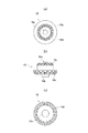
この開閉操作時のフリクショントルク及び吸込み機能について、図12〜図15を参照しつつ更に説明する。図12の(a)には、端末機器の1例であるノートパソコン1の第1筐体2と第2筐体3(いずれも、図12〜15中において想像線で示す。)の閉成状態(開度0°)が示されており、(b)図にはそのときの前記吸込み手段26のカムプレート部材27とカムフォロワー部材28との接触状態が示されている。(b)図において、カムプレート部材27については、そのカム凹部27cよりも隆起した平坦部27dに斜線を施してあり、カムフォロワー部材28については、その平坦部28cよりも隆起したカム凸部28bに細かい点模様を施してある。この開度0°の状態において、カムフォロワー部材28の傾斜部28d、28eは、カムプレート部材27の傾斜部27e、27fと部分的に重なり合うため、前記弾性手段29の押圧力によって、カムフォロワー部材28のカム凸部28bがカムプレート部材27のカム凹部27c内に落ち込む方向、即ち、図12の(b)図において、カムフォロワー部材28(そして第2ヒンジシャフト12)を時計回りに回転させる方向の力(吸込み手段26による吸込み力)が生じ、これに伴って前記同期回転手段15を介して、第1ヒンジシャフト11(そして第2筐体3)を反時計回りに回転させる方向の力(吸込み力)が生じる。そして、この吸込み作用によって、第1筐体2と第2筐体3の閉成状態において、第1筐体2と第2筐体3の間にラッチ手段等を設けなくとも、自然に第1筐体2及び第2筐体3が開いてしまうことなく閉成状態を保持できるものである。
The friction torque and the suction function during the opening / closing operation will be further described with reference to FIGS. 12 to 15. In FIG. 12A, the
次いで、図13(a)に示すように、第1筐体2を机上等で水平に保ったまま、第2筐体3を時計方向へ例えば45°まで開くと、前記同期回転手段15(図5参照)の作用により、まず、第1ヒンジシャフト11が時計方向へ45°回転し、共に回転する第1ギア16の第1傘歯部16bが噛み合っている中間ギア18の上部傘歯部18cを介して当該中間ギア18が反時計方向へ45°回転し、この中間ギア18の下部傘歯部18dと、その第2傘歯部17bを噛み合わせている第2ヒンジシャフト12に取り付けた第2ギア17が反時計方向へ回転することから、第2ヒンジシャフト12が第1ヒンジシャフト11とは反対方向へ45°回転することになる。これに伴い、図13(b)に示すように、第2ヒンジシャフト12と一緒に回転するカムフォロワー部材28も反時計方向へ45°回転し、カムフォロワー部材28のカム凸部28bの半分以上がカムプレート部材27の平坦部27d上に乗り上げた状態となる。そのため、弾性手段29の弾性部材29a、29aは図12のときよりも圧縮されることとなり、その弾性力が増大することによって、前記フリクショントルク発生手段20によるフリクショントルクが増加し、第2筐体3の開閉動作時の任意の角度位置における安定停止(チルト)作用を確保できるものである。
Next, as shown in FIG. 13A, when the
以下、同様にして、第2筐体3を時計方向へ例えば90°まで開いた状態を図14に示し、さらに、本実施例における限界角度の略190°まで開いた状態を図15に示す。これらの状態においても、カムフォロワー部材28のカム凸部28bがカムプレート部材27の平坦部27d上に乗り上げた状態が維持され、第2筐体3の任意の角度位置における安定停止作用が維持できる。また、図15に示したような限界角度まで開いた場合においても、第1ヒンジシャフト11と第2ヒンジシャフト12が取付部材14に設けた軸受部14bに上下方向に位置して取り付けられているので、第2筐体3が第1筐体2の後側面に設けられた前記のLANポート6bやUSBポート6c、6d(図1参照)、等々の各種ポートに接続された各種プラグやケーブルと干渉することがなく、それらの使用が妨げられることがない。また、第1筐体2の後側面に排熱口が設けられている場合には、それを塞ぐこともない。尚、第2筐体3を過剰に開くことによって、第1筐体2や第2筐体3が損傷等するのを防止するため、第2筐体3を所定の開度位置で停止させるストッパーを、例えば第1ヒンジシャフト11と取付部材14との相互間に設けるようにしても良い。
Hereinafter, in the same manner, FIG. 14 shows a state in which the
第2筐体3を閉じる場合には、第1ヒンジシャフト11及び第2ヒンジシャフト12が上記とは逆方向へ回転し、図12に示すようなカムフォロワー部材28のカム凸部28bがカムプレート部材27のカム凹部27c内に吸い込まれる角度位置に近づくと、その吸込み作用によって第2筐体3が自動的に閉じる方向へ回転付勢される。
When the
尚、その他の実施例としては、図示は省略するが、前記第1ギア16と第2ギア17を平歯車にして、互いに中間ギアを介さずに直接噛み合うように構成することができる。また、弾性手段29に用いている弾性部材29a、29aは、これらを圧縮コイルスプリング或は弾性を備えたゴムを始めとする合成樹脂製のものなどに代えることが可能である。また、2軸ヒンジ4や5をノートパソコン1へ取り付けた際に、同期回転手段15や、フリクショントルク発生手段20、吸込み手段26、弾性手段29等が外部へ露出して外観を損なうのを防止するよう、これら全体をカバーし得るヒンジケースを設けることも推奨される。
In addition, as another embodiment, although not shown, the
本発明は以上のように構成したので、メインのフリクショントルク発生手段や吸込み手段を第2ヒンジシャフト上に設けることによって必要なフリクショントルクを確保し、第1ヒンジシャフト側の第2筐体の薄型化が可能になると共に、第2筐体の開成時に第1筐体の後側面に設けられた各種ポートに接続された各種プラグやケーブルに対して第2筐体の後側面がぶつかったり、排熱口が塞がれたりして、それらの機能が妨げられることのない、適応性に優れた2軸ヒンジとして好適に用いることができる。 Since the present invention is configured as described above, the required friction torque is secured by providing the main friction torque generating means and suction means on the second hinge shaft, and the second housing on the first hinge shaft side is thin. The rear side surface of the second housing collides with various plugs and cables connected to various ports provided on the rear side surface of the first housing when the second housing is opened. It can be suitably used as a highly adaptable biaxial hinge that does not block the hot port and hinder their functions.
1 ノートパソコン
2 第1筐体
2a キーボード部
3 第2筐体
3a ディスプレイ部
4、5 2軸ヒンジ
6a 電源コネクタ
6b LANポート
6c、6d USBポート
7 電源プラグ
11 第1ヒンジシャフト
11a 取付板部
11b、11b 取付孔
11c フランジ部
11d 変形軸部
11e 雄ネジ部
12 第2ヒンジシャフト
12a フランジ部
12b 変形軸部
12c 雄ネジ部
13 取付プレート
13a〜13c 取付孔
13d 取付ピン
13e、13f 取付ネジ
14 ギアサポート部材を兼ねる取付部材
14a 取付プレート部
14b 軸受部
14c 第1軸受孔
14d 第2軸受孔
14f 第1軸支溝
14g 第2軸支溝
14h、14h 取付孔
14i、14i 取付ネジ
14j 小径部
14k 大径部
15 同期回転手段
16 第1ギア
16a 変形挿通孔
16b 第1傘歯部
17 第2ギア
17a 変形挿通孔
17b 第2傘歯部
18 中間ギア
18a 上部支軸
18b 下部支軸
18c 上部傘歯部
18d 下部傘歯部
19 回転制御手段
20a サブのフリクショントルク発生手段
20b メインのフリクショントルク発生手段
21 フリクションプレート
21a 第1軸受孔
21b 第2軸受孔
21c ナナコメ加工部
21d ナナコメ加工部
21e 係止孔
21f 小径部
21g 大径部
22 第1ワッシャー
22a 変形挿通孔
22b ナナコメ加工部
23 フリクションワッシャー
23a 変形挿通孔
23b ナナコメ加工部
24 第2ワッシャー
24a 変形挿通孔
25 第1締付ナット
25a 雌ネジ孔
26 吸込み手段
27 カムプレート部材
27a 軸受孔
27b 係止凸片
27c カム凹部
27d 平坦部
27e、27f 傾斜部
28 カムフォロワー部材
28a 変形挿通孔
28b カム凸部
28c 平坦部
28d、28e 傾斜部
29 弾性手段
29a 弾性部材
29b 円形挿通孔
30 第2押えワッシャー
30a 変形挿通孔
31 第2締付ナット
31a 雌ネジ孔
1 Laptop 2 1st housing 2a Keyboard part 3 2nd housing 3a Display part 4, 5 2-axis hinge 6a Power connector 6b LAN port 6c, 6d USB port 7 Power plug 11 1st hinge shaft 11a Mounting plate part 11b, 11b Mounting hole 11c Flange part 11d Deformed shaft part 11e Male threaded part 12 Second hinge shaft 12a Flange part 12b Deformed shaft part 12c Male threaded part 13 Mounting plate 13a to 13c Mounting hole 13d Mounting pin 13e, 13f Mounting screw 14 Gear support member 14a Mounting plate part 14b Bearing part 14c 1st bearing hole 14d 2nd bearing hole 14f 1st shaft support groove 14g 2nd shaft support groove 14h, 14h Mounting holes 14i, 14i Mounting screw 14j Small diameter part 14k Large diameter part 15 Synchronous rotation means 16 1st gear 16a Deformation insertion hole 16b 1st capsular tooth 17 2nd gear 17a Deformation insertion hole 17b 2nd capsular tooth 18 Intermediate gear 18a Upper bearing 18b Lower bearing 18c Upper bearing 18d Lower Gear tooth 19 Rotation control means 20a Sub friction torque generating means 20b Main friction torque generating means 21 Friction plate 21a 1st bearing hole 21b 2nd bearing hole 21c Nana rice processing part 21d Nana rice processing part 21e Locking hole 21f Small diameter part 21g Large diameter part 22 1st washer 22a Deformation insertion hole 22b Nana rice processing part 23 Friction washer 23a Deformation insertion hole 23b Nana rice processing part 24 2nd washer 24a Deformation insertion hole 25 1st tightening nut 25a Female screw hole 26 Suction means 27 Member 27a Bearing hole 27b Locking convex piece 27c Cam recess 27d Flat part 27e, 27f Inclined part 28 Cam follower member 28a Deformed insertion hole 28b Cam convex part 28c Flat part 28d, 28e Inclined part 29 Elastic member 29b Circular insertion hole 30 2nd presser foot washer 30a Deformation insertion hole 31 2nd tightening nut 31a Female screw hole
Claims (7)
前記第1筐体へ取り付けられる取付プレート部とこの取付プレート部から上方へ立設した大径部と小径部を有する軸受部から成る取付部材と、
この取付部材の前記小径部に回転可能に軸支されると共に、取付プレートを介して前記第2筐体へ取り付けられる外径の細い第1ヒンジシャフトと、
前記取付部材の前記大径部に前記第1ヒンジシャフトと平行状態を保ちつつ軸方向へ位置をずらせて回転可能に軸支される前記第1ヒンジシャフトより外径の太い第2ヒンジシャフトと、
前記第1ヒンジシャフトと前記第2ヒンジシャフトの間に設けられる一方のヒンジシャフトの回転に同期して他方のヒンジシャフトを互いに異なる方向に回転させる同期回転手段とを有し、
前記第1ヒンジシャフトの側には、当該第1ヒンジシャフトの回転時にフリクショントルクを発生させるサブのフリクショントルク発生手段を設け、
前記第2ヒンジシャフトの側には、当該第2ヒンジシャフトの回転時に前記第1ヒンジシャフトの側のサブのフリクショントルク発生手段と較べて強いフリクショントルクを発生させるメインのフリクショントルク発生手段と、当該第2ヒンジシャフトをその所定の回転角度から一方向へ回転付勢させて自動的に回転させる吸込み手段とを設け、この吸込み手段による前記第2ヒンジシャフトの回転を、前記同期回転手段を介して前記第1ヒンジシャフトへ伝達させることを特徴とする、2軸ヒンジ。 A biaxial hinge that connects the second housing to the first housing of the terminal device so that it can be opened and closed.
A mounting member comprising a bearing portion having a large diameter portion and a small diameter portion provided upright upwardly and the mounting plate portion attached to the first housing from the mounting plate portion,
A first hinge shaft having a small outer diameter, which is rotatably supported by the small diameter portion of the mounting member and mounted to the second housing via a mounting plate,
A second hinge shaft having a larger outer diameter than the first hinge shaft, which is rotatably supported by shifting the position in the axial direction while maintaining a parallel state with the first hinge shaft on the large diameter portion of the mounting member.
It has a synchronous rotation means provided between the first hinge shaft and the second hinge shaft, which rotates the other hinge shaft in different directions in synchronization with the rotation of one hinge shaft.
A sub-friction torque generating means for generating friction torque when the first hinge shaft rotates is provided on the side of the first hinge shaft.
Wherein the side of the second hinge shaft, and the main friction torque generating means for generating the sub friction torque generating means and compared with a strong friction torque on the side of the first hinge shaft upon rotation of the second hinge shaft, the A suction means for automatically rotating the second hinge shaft by rotating it in one direction from its predetermined rotation angle is provided, and the rotation of the second hinge shaft by the suction means is performed via the synchronous rotation means. A biaxial hinge characterized by transmitting to the first hinge shaft .
前記第1ヒンジシャフトに回転を拘束されて取り付けられた第1ギアと、
前記第2ヒンジシャフトに回転を拘束されて取り付けられた前記第1ギアより大径の第2ギアと、
前記第1ギアと前記第2ギアとの間に設けられ、一方の回転を他方に伝え、それぞれ異なる方向へ回転させる中間ギアと、
で構成したことを特徴とする、請求項1に記載の2軸ヒンジ。 The synchronous rotation means
The first gear attached to the first hinge shaft with rotation restrained,
A second gear having a diameter larger than that of the first gear, which is attached to the second hinge shaft with its rotation restricted.
An intermediate gear provided between the first gear and the second gear, which transmits one rotation to the other and rotates in different directions.
The biaxial hinge according to claim 1, wherein the hinge is made of.
前記第1ヒンジシャフトに回転を拘束されて取り付けられた第1ギアと、
前記第2ヒンジシャフトに回転を拘束されて取り付けられ、前記第1ギアと噛み合わせられて前記第1ギアと異なる方向へ回転する前記第1ギアより大径の第2ギアと、
で構成したことを特徴とする、請求項1に記載の2軸ヒンジ。 The synchronous rotation means
The first gear attached to the first hinge shaft with rotation restrained,
A second gear having a diameter larger than that of the first gear, which is attached to the second hinge shaft with its rotation constrained and meshed with the first gear to rotate in a direction different from that of the first gear.
The biaxial hinge according to claim 1, wherein the hinge is made of.
前記第1ヒンジシャフトと前記第2ヒンジシャフトを回転可能に挿通させたフリクションプレートと、
前記第2ヒンジシャフト上に回転を拘束された状態で装着され、前記取付部材の前記軸受部の前記大径部と前記フリクションプレートの大径部との間に介在されるフリクションワッシャーと、
前記フリクションワッシャーに前記取付部材と前記フリクションプレートを圧接するために前記第2ヒンジシャフト上に設けられた弾性手段と、
で構成したことを特徴とする、請求項1に記載の2軸ヒンジ。 The main friction torque generating means
A friction plate through which the first hinge shaft and the second hinge shaft are rotatably inserted,
A friction washer that is mounted on the second hinge shaft in a state where rotation is restricted and is interposed between the large diameter portion of the bearing portion of the mounting member and the large diameter portion of the friction plate.
An elastic means provided on the second hinge shaft for pressing the mounting member and the friction plate against the friction washer, and
The biaxial hinge according to claim 1, wherein the hinge is made of.
前記第1ヒンジシャフトと前記第2ヒンジシャフトを回転可能に挿通させたフリクションプレートと、
前記フリクションプレートの小径部の一方の側と前記取付部材の軸受部の小径部との間に前記第1ヒンジシャフトに回転を拘束されて配置された第1ワッシャーと、
前記フリクションプレートの小径部の他方の側と前記第1ヒンジシャフトにネジ着させた第1締付ナットとの間に前記第1ヒンジシャフトの回転を拘束させて配置された第2ワッシャーと、
で構成したことを特徴とする、請求項1に記載の2軸ヒンジ。 The sub-friction torque generating means
A friction plate through which the first hinge shaft and the second hinge shaft are rotatably inserted,
A first washer arranged with rotation restrained by the first hinge shaft between one side of the small diameter portion of the friction plate and the small diameter portion of the bearing portion of the mounting member.
A second washer arranged to restrain the rotation of the first hinge shaft between the other side of the small diameter portion of the friction plate and the first tightening nut screwed to the first hinge shaft.
The biaxial hinge according to claim 1, wherein the hinge is made of.
フリクションプレートに係止させて前記第2ヒンジシャフトを回転可能に挿通させると共に、その一側部外側に略円弧状のカム凹部又はカム凸部を備えたカムプレート部材と、
前記第2ヒンジシャフトに回転を拘束されて取り付けられ、前記カムプレート部材の前記カム凹部又はカム凸部と対向する面にカム凸部又はカム凹部を有するカムフォロワー部材と、
第2ヒンジシャフト上に設けられた前記カムプレート部材と前記カムフォロワー部材とを互いに圧接させる弾性手段と、
で構成したことを特徴とする、請求項1に記載の2軸ヒンジ。 The suction means
A cam plate member that is locked to a friction plate to rotatably insert the second hinge shaft and has a substantially arc-shaped cam recess or cam protrusion on the outside of one side thereof.
A cam follower member which is attached to the second hinge shaft with rotation restrained and has a cam convex portion or a cam concave portion on a surface of the cam plate member facing the cam concave portion or the cam convex portion.
An elastic means for pressing the cam plate member and the cam follower member provided on the second hinge shaft with each other.
The biaxial hinge according to claim 1, wherein the hinge is made of.
Applications Claiming Priority (2)
| Application Number | Priority Date | Filing Date | Title |
|---|---|---|---|
| CN201610186631.6A CN107228119B (en) | 2016-03-25 | 2016-03-25 | Biaxial hinge and terminal machine using the same |
| CN201610186631.6 | 2016-03-25 |
Publications (3)
| Publication Number | Publication Date |
|---|---|
| JP2017172784A JP2017172784A (en) | 2017-09-28 |
| JP2017172784A5 JP2017172784A5 (en) | 2019-05-09 |
| JP6788997B2 true JP6788997B2 (en) | 2020-11-25 |
Family
ID=59896839
Family Applications (1)
| Application Number | Title | Priority Date | Filing Date |
|---|---|---|---|
| JP2016092830A Active JP6788997B2 (en) | 2016-03-25 | 2016-05-02 | 2-axis hinge and terminal equipment using this 2-axis hinge |
Country Status (5)
| Country | Link |
|---|---|
| US (1) | US10000955B2 (en) |
| JP (1) | JP6788997B2 (en) |
| KR (1) | KR101937557B1 (en) |
| CN (1) | CN107228119B (en) |
| TW (1) | TWI634412B (en) |
Families Citing this family (29)
| Publication number | Priority date | Publication date | Assignee | Title |
|---|---|---|---|---|
| US10501973B2 (en) * | 2016-06-14 | 2019-12-10 | Microsoft Technology Licensing, Llc | Hinge with free-stop function |
| TWM536198U (en) * | 2016-08-24 | 2017-02-01 | First Dome Corp | Dual-axis transmission device and transmission module |
| TWI642856B (en) * | 2016-11-03 | 2018-12-01 | 緯創資通股份有限公司 | Hinge module and assembling method |
| US9927845B1 (en) * | 2016-11-04 | 2018-03-27 | Lenovo (Singapore) Pte. Ltd. | Hinge assembly |
| CN207005077U (en) * | 2017-04-27 | 2018-02-13 | 杭州安费诺飞凤通信部品有限公司 | The two-shaft hinge mechanism and mobile terminal applied on mobile terminal |
| JP6890829B2 (en) * | 2017-08-17 | 2021-06-18 | 株式会社ナチュラレーザ・ワン | Parallel 2-axis hinges and electronic devices |
| WO2019045709A1 (en) * | 2017-08-31 | 2019-03-07 | Hewlett-Packard Development Company, L.P. | Hinge assembly with vertical torque engine |
| WO2019107854A1 (en) | 2017-11-28 | 2019-06-06 | Samsung Electronics Co., Ltd. | Foldable display device |
| CN107977049A (en) * | 2017-12-27 | 2018-05-01 | 昆山玮硕恒基智能科技股份有限公司 | Cam drive and apply its electronic equipment |
| TWI699155B (en) * | 2018-03-02 | 2020-07-11 | 仁寶電腦工業股份有限公司 | Hinge structure and electronic device having same |
| WO2019194796A1 (en) * | 2018-04-04 | 2019-10-10 | Hewlett-Packard Development Company, L.P. | Dual-axis hinge assemblies |
| KR20190124110A (en) * | 2018-04-25 | 2019-11-04 | (주)오라컴디스플레이 | Infolding Hinge Structure for Flexible Display Panel |
| JP7085407B2 (en) * | 2018-05-17 | 2022-06-16 | 加藤電機株式会社 | Switchgear of switchgear and switchgear |
| TWI718784B (en) * | 2018-12-04 | 2021-02-11 | 仁寶電腦工業股份有限公司 | Hinge assembly and electronic device using the same |
| US10983569B2 (en) * | 2018-12-07 | 2021-04-20 | Compal Electronics, Inc. | Hidden hinge and electronic device having the same |
| TWI691826B (en) * | 2019-01-08 | 2020-04-21 | 宏碁股份有限公司 | Electronic device and hinge mechanism of the same |
| CN109882498B (en) * | 2019-04-16 | 2024-03-12 | 泰州市创新电子有限公司 | Double-shaft hinge and portable electronic device |
| CN109899377B (en) * | 2019-04-24 | 2024-02-23 | 泰州市创新电子有限公司 | Biaxial hinge and portable electronic device |
| TWI693352B (en) * | 2019-06-25 | 2020-05-11 | 富世達股份有限公司 | Folding screen device and hinge mechanism |
| CN112814992B (en) * | 2019-11-18 | 2022-04-26 | 昆山纬绩资通有限公司 | Double-shaft pivot mechanism and electronic device comprising same |
| CN113280034B (en) * | 2020-02-19 | 2022-07-22 | 苏州佳世达光电有限公司 | Rotating shaft module, electronic device bracket and electronic device |
| US11599155B2 (en) * | 2020-04-21 | 2023-03-07 | Microsoft Technology Licensing, Llc | Hinged device |
| KR102260987B1 (en) * | 2020-07-03 | 2021-06-04 | 주식회사 서진시스템 | electronic devices having movable block and 2-axial hinge structure |
| TWI769560B (en) * | 2020-10-19 | 2022-07-01 | 華碩電腦股份有限公司 | Electronic device |
| KR20220052096A (en) * | 2020-10-20 | 2022-04-27 | 삼성전자주식회사 | A hinge module and foldable electronic device including the same |
| KR102394122B1 (en) * | 2021-01-08 | 2022-05-13 | 주식회사 서진시스템 | electronic devices having 2-axial hinge structure |
| TWI783789B (en) * | 2021-11-23 | 2022-11-11 | 富世達股份有限公司 | Front and rear sliding hinges |
| TWI804106B (en) * | 2021-12-16 | 2023-06-01 | 富世達股份有限公司 | Gear Synchronous Hinge |
| JP7457091B1 (en) | 2022-12-07 | 2024-03-27 | レノボ・シンガポール・プライベート・リミテッド | Electronics |
Family Cites Families (30)
| Publication number | Priority date | Publication date | Assignee | Title |
|---|---|---|---|---|
| JPH09303032A (en) * | 1996-05-16 | 1997-11-25 | Kato Electrical Mach Co Ltd | Tilt hinge |
| JP2005023955A (en) * | 2003-06-30 | 2005-01-27 | Casio Comput Co Ltd | Hinge structure, image pickup device and cellular phone device |
| US20070270197A1 (en) * | 2006-05-16 | 2007-11-22 | Chang-Ling Hsieh | Mobile device with a rotary assembly |
| JP2012237392A (en) | 2011-05-12 | 2012-12-06 | Katoh Electrical Machinery Co Ltd | Parallel biaxial hinge and small-sized electronic apparatus equipped with the parallel biaxial hinge |
| CN202251417U (en) * | 2011-09-28 | 2012-05-30 | 兆利科技工业股份有限公司 | Double-mandrel turning-type hinging machine |
| CN202634502U (en) * | 2012-03-31 | 2012-12-26 | 三星电子株式会社 | Double-shaft gear hinge device and flip-type portable terminal |
| JP6179199B2 (en) * | 2013-06-04 | 2017-08-16 | 富士通株式会社 | HINGE DEVICE AND ELECTRONIC DEVICE PROVIDED WITH THE HINGE DEVICE |
| WO2015012830A1 (en) * | 2013-07-25 | 2015-01-29 | Hewlett-Packard Development Company, L.P. | Hinge assembly for a computing device |
| TWM468131U (en) * | 2013-08-16 | 2013-12-11 | I3G Design Co Ltd | Hinge device |
| CN203477049U (en) * | 2013-09-13 | 2014-03-12 | 连鋐科技股份有限公司 | Large-angle biaxial pivot |
| CN104613085A (en) * | 2013-11-05 | 2015-05-13 | 昆山万禾精密电子有限公司 | Synchronous rotary biaxial hinge |
| US9127490B2 (en) * | 2013-12-05 | 2015-09-08 | Lianhong Art Co., Ltd. | Transmission mechanism for dual-shaft hinge |
| TWM478991U (en) * | 2013-12-17 | 2014-05-21 | First Dome Corp | Parallelism fixing device for dual rotary shaft |
| US20150342068A1 (en) * | 2014-05-22 | 2015-11-26 | Sinher Technology Inc. | Durable synchronous opening and closing mechanism |
| CN105179459B (en) * | 2014-06-12 | 2021-01-22 | 加藤电机(香港)有限公司 | Double-shaft hinge and terminal machine using same |
| TWI644608B (en) * | 2014-07-14 | 2018-12-11 | 富世達股份有限公司 | Double shaft synchronous transmission |
| TWI603006B (en) * | 2014-07-14 | 2017-10-21 | First Dome Corp | Pivoting device for hinged hinge |
| TWI603007B (en) * | 2014-07-31 | 2017-10-21 | First Dome Corp | Double shaft synchronous drive fixing device |
| JP2016037979A (en) * | 2014-08-05 | 2016-03-22 | 株式会社ナチュラレーザ・ワン | Tilt hinge and notebook personal computer using the same |
| CN105465161A (en) * | 2014-09-03 | 2016-04-06 | 联想(北京)有限公司 | Double-rotary-shaft pivoting device and electronic equipment |
| JP6590135B2 (en) * | 2014-10-14 | 2019-10-16 | 株式会社ナチュラレーザ・ワン | Biaxial hinge and electronic device using the biaxial hinge |
| CN105889308B (en) * | 2015-01-26 | 2019-01-15 | 联想(北京)有限公司 | Connector and electronic device with connector |
| TWM509367U (en) * | 2015-05-29 | 2015-09-21 | Lian Hong Art Co Ltd | Oblique biaxial hinge connector |
| CN204716733U (en) * | 2015-06-18 | 2015-10-21 | 兆利科技工业股份有限公司 | Biaxial linkage type rotating shaft |
| TWM511564U (en) * | 2015-06-26 | 2015-11-01 | Lian Hong Art Co Ltd | Large-small shaft differential ratio pivot device |
| TWM521869U (en) * | 2015-11-30 | 2016-05-11 | Lian Hong Art Co Ltd | Interleaving shaft integrally dual-shaft synchronous hinge |
| CN105528035A (en) * | 2015-12-31 | 2016-04-27 | 联想(北京)有限公司 | Electronic equipment |
| US20170235337A1 (en) * | 2016-02-11 | 2017-08-17 | Kabushiki Kaisha Toshiba | Electronic apparatus comprising two casing coupled together with two-parallel-axis hinge |
| JP6797393B2 (en) * | 2016-06-02 | 2020-12-09 | 株式会社ナチュラレーザ・ワン | 2-axis hinge and terminal equipment using this 2-axis hinge |
| KR102499448B1 (en) * | 2016-07-21 | 2023-02-15 | 삼성전자주식회사 | electronic device including hinge structure |
-
2016
- 2016-03-25 CN CN201610186631.6A patent/CN107228119B/en active Active
- 2016-05-02 JP JP2016092830A patent/JP6788997B2/en active Active
-
2017
- 2017-03-17 TW TW106109023A patent/TWI634412B/en active
- 2017-03-20 US US15/463,587 patent/US10000955B2/en active Active
- 2017-03-22 KR KR1020170035974A patent/KR101937557B1/en active IP Right Grant
Also Published As
| Publication number | Publication date |
|---|---|
| CN107228119B (en) | 2020-02-28 |
| JP2017172784A (en) | 2017-09-28 |
| TW201734327A (en) | 2017-10-01 |
| US20170275935A1 (en) | 2017-09-28 |
| TWI634412B (en) | 2018-09-01 |
| KR101937557B1 (en) | 2019-01-10 |
| KR20170113176A (en) | 2017-10-12 |
| CN107228119A (en) | 2017-10-03 |
| US10000955B2 (en) | 2018-06-19 |
Similar Documents
| Publication | Publication Date | Title |
|---|---|---|
| JP6788997B2 (en) | 2-axis hinge and terminal equipment using this 2-axis hinge | |
| JP6324833B2 (en) | Biaxial hinge and terminal device using the biaxial hinge | |
| CN105404357B (en) | Computing device | |
| JP6338176B2 (en) | Biaxial hinge and terminal device using the biaxial hinge | |
| JP6764181B2 (en) | 3-axis hinges and electronic devices using these 3-axis hinges | |
| US9223347B2 (en) | Display panel device | |
| JP6355233B2 (en) | Biaxial hinge and terminal device using the biaxial hinge | |
| JP6338177B2 (en) | Biaxial hinge and terminal device using the biaxial hinge | |
| KR20130135091A (en) | Biaxial hinge | |
| JP2017172784A5 (en) | ||
| US20170192467A1 (en) | Hinge assemblies | |
| JP2015148296A5 (en) | ||
| US20080034550A1 (en) | Hinge unit with auto-lock and double-side rotation | |
| JP2005337301A (en) | Hinge device and electronic device using hinge device | |
| US20180224899A1 (en) | Hinge mechanism for a computing device | |
| TW201640989A (en) | Two-shaft hinge and terminal apparatus using the same | |
| US10296056B2 (en) | Bell crank linked hinge mechanism for a computing device | |
| CN103809685A (en) | Portable electronic device with pin joint structure | |
| US20180224900A1 (en) | Hinge mechanism for a computing device | |
| TW201326590A (en) | Latch locking type dual-shaft hinge device | |
| KR200472450Y1 (en) | Hinge assembly | |
| TWI490420B (en) | Rotary stop type biaxial hub | |
| WO2021210075A1 (en) | Raising/lowering-type biaxial hinge and terminal apparatus using said raising/lowering-type biaxial hinge | |
| TWM447660U (en) | Dual-axial hinge capable of opening and closing smoothly | |
| KR101021808B1 (en) | Swing Hinge Apparatus and Electronic Appliance having it |
Legal Events
| Date | Code | Title | Description |
|---|---|---|---|
| A521 | Request for written amendment filed |
Free format text: JAPANESE INTERMEDIATE CODE: A523 Effective date: 20160524 |
|
| A521 | Request for written amendment filed |
Free format text: JAPANESE INTERMEDIATE CODE: A523 Effective date: 20190322 |
|
| A621 | Written request for application examination |
Free format text: JAPANESE INTERMEDIATE CODE: A621 Effective date: 20190322 |
|
| A131 | Notification of reasons for refusal |
Free format text: JAPANESE INTERMEDIATE CODE: A131 Effective date: 20200331 |
|
| A521 | Request for written amendment filed |
Free format text: JAPANESE INTERMEDIATE CODE: A523 Effective date: 20200629 |
|
| TRDD | Decision of grant or rejection written | ||
| A01 | Written decision to grant a patent or to grant a registration (utility model) |
Free format text: JAPANESE INTERMEDIATE CODE: A01 Effective date: 20201006 |
|
| A61 | First payment of annual fees (during grant procedure) |
Free format text: JAPANESE INTERMEDIATE CODE: A61 Effective date: 20201102 |
|
| R150 | Certificate of patent or registration of utility model |
Ref document number: 6788997 Country of ref document: JP Free format text: JAPANESE INTERMEDIATE CODE: R150 |
|
| R250 | Receipt of annual fees |
Free format text: JAPANESE INTERMEDIATE CODE: R250 |