JP6788384B2 - Image forming device - Google Patents
Image forming device Download PDFInfo
- Publication number
- JP6788384B2 JP6788384B2 JP2016113800A JP2016113800A JP6788384B2 JP 6788384 B2 JP6788384 B2 JP 6788384B2 JP 2016113800 A JP2016113800 A JP 2016113800A JP 2016113800 A JP2016113800 A JP 2016113800A JP 6788384 B2 JP6788384 B2 JP 6788384B2
- Authority
- JP
- Japan
- Prior art keywords
- image
- mode
- page
- monochromatic
- multicolor
- Prior art date
- Legal status (The legal status is an assumption and is not a legal conclusion. Google has not performed a legal analysis and makes no representation as to the accuracy of the status listed.)
- Active
Links
Images


Classifications
-
- G—PHYSICS
- G03—PHOTOGRAPHY; CINEMATOGRAPHY; ANALOGOUS TECHNIQUES USING WAVES OTHER THAN OPTICAL WAVES; ELECTROGRAPHY; HOLOGRAPHY
- G03G—ELECTROGRAPHY; ELECTROPHOTOGRAPHY; MAGNETOGRAPHY
- G03G15/00—Apparatus for electrographic processes using a charge pattern
- G03G15/50—Machine control of apparatus for electrographic processes using a charge pattern, e.g. regulating differents parts of the machine, multimode copiers, microprocessor control
-
- G—PHYSICS
- G03—PHOTOGRAPHY; CINEMATOGRAPHY; ANALOGOUS TECHNIQUES USING WAVES OTHER THAN OPTICAL WAVES; ELECTROGRAPHY; HOLOGRAPHY
- G03G—ELECTROGRAPHY; ELECTROPHOTOGRAPHY; MAGNETOGRAPHY
- G03G15/00—Apparatus for electrographic processes using a charge pattern
- G03G15/01—Apparatus for electrographic processes using a charge pattern for producing multicoloured copies
- G03G15/0105—Details of unit
- G03G15/0131—Details of unit for transferring a pattern to a second base
- G03G15/0136—Details of unit for transferring a pattern to a second base transfer member separable from recording member or vice versa, mode switching
Landscapes
- Physics & Mathematics (AREA)
- General Physics & Mathematics (AREA)
- Engineering & Computer Science (AREA)
- Microelectronics & Electronic Packaging (AREA)
- Color Electrophotography (AREA)
- Control Or Security For Electrophotography (AREA)
- Electrostatic Charge, Transfer And Separation In Electrography (AREA)
Description
本発明は画像形成装置に関する。 The present invention relates to an image forming apparatus.
電子写真方式の画像形成装置は、それぞれ色の異なるトナー画像を重畳して多色画像を形成したり、ブラックのトナーだけを用いて単色画像を形成したりする。このような画像形成装置では、トナーの色ごとに感光体が設けられている。各感光体が中間転写ベルトに当接しているため、各感光体は摩耗する。感光体の摩耗を軽減するために、単色モードではブラックのトナー画像を担持する感光体のみが中間転写ベルトに当接し、他の色のトナー画像を担持する感光体は間転写ベルトから離間している。多色モードではすべての感光体が中間転写モードに当接する。感光体と中間転写ベルトとを当接させたり、離間させたりするにはある程度の時間が必要となる。とりわけ、多色画像と単色画像とが混在する画像形成ジョブにおいて、頻繁に当接・離間を実行すると、画像形成の生産性が低下する。 The electrophotographic image forming apparatus superimposes toner images of different colors to form a multicolor image, or forms a monochromatic image using only black toner. In such an image forming apparatus, a photoconductor is provided for each color of the toner. Since each photoconductor is in contact with the intermediate transfer belt, each photoconductor wears. In order to reduce wear on the photoconductor, in the monochromatic mode, only the photoconductor carrying the black toner image abuts on the intermediate transfer belt, and the photoconductor carrying the toner image of another color is separated from the inter-transfer belt. There is. In the multicolor mode, all photoconductors come into contact with the intermediate transfer mode. A certain amount of time is required to bring the photoconductor and the intermediate transfer belt into contact with each other or to separate them from each other. In particular, in an image forming job in which a multicolor image and a monochromatic image are mixed, if abutting / separating is performed frequently, the productivity of image forming is lowered.
特許文献1によれば、フルカラーモードで印刷中に、後続のモノクロ画像の連続数が閾値未満の場合にはフルカラーモードを継続し、閾値以上の場合にはモノクロモードへ切り替えることが提案されている。これにより、フルカラーとモノクロの混在プリント時における生産性と効率が高められるという。
According to
しかし、特許文献1では紙間の長さとは無関係にフルカラーモードがモノクロモードへ切り替えられたり、モノクロモードがフルカラーモードへ切り替えられたりしてしまう。そのため、画像形成ジョブの全体で見ると、生産性が低下するケースが存在する。なお、紙間とは、搬送路において先行するページと後続のページとの間に存在する距離や、この距離に応じた処理待ち時間のことである。一般に紙間は生産性を高めるために短く設定されるが、ジョブの内容によっては紙間が通常の紙間よりも相対的に長い紙間となるように延長されることがある。したがって、このような相対的に長い紙間を利用してモードを切り替えれば生産性が向上するだろう。そこで、本発明は、単色画像と多色画像とが混在するジョブにおける生産性を向上させることを目的とする。
However, in
本発明は、たとえば、
第一色のトナーを用いて第一感光体に画像を形成する第一形成手段と、
第二色のトナーを用いて第二感光体に画像を形成する第二形成手段と、
前記第一形成手段により前記第一感光体に形成された画像および前記第二形成手段により前記第二感光体に形成された画像が転写される中間転写体と、
前記第一感光体と前記第二感光体との双方に前記中間転写体が当接している状態で画像が形成される多色モードと、前記第一感光体に前記中間転写体が当接し前記第二感光体から前記中間転写体が離間している状態で画像が形成される単色モードとに変位させる当接離間手段と、
前記第一形成手段および前記第二形成手段を制御し、前記第一色のトナーを用いた画像と前記第二色のトナーを用いた画像とを重畳した多色画像を形成させるか、または、前記第二色のトナーを使用せずに前記第一色のトナーを用いた単色画像を形成させる制御手段と、を有し、
前記制御手段は、
前記多色画像が形成されるページと前記単色画像が形成されるページとが混在するジョブが投入され、前記ジョブの途中で前記単色モードから前記多色モードへの切り替えを行う場合に、前記ジョブを解析することにより、前記ジョブにおける前記多色画像が形成されるページよりも前の複数のページにおいて隣り合うページ間の処理待ち時間を判別し、各ページ間の処理待ち時間のうち相対的に長い処理待ち時間を特定し、特定された相対的に長い処理待ち時間が前記多色モードと前記単色モードとの切り替えに要する時間よりも短くても、当該相対的に長い処理待ち時間において、前記単色モードから前記多色モードへ切り替えることを特徴とする画像形成装置を提供する。
The present invention is, for example,
The first forming means for forming an image on the first photoconductor using the first color toner,
A second forming means for forming an image on the second photoconductor using a second color toner,
An intermediate transfer body to which an image formed on the first photoconductor by the first forming means and an image formed on the second photoconductor by the second forming means are transferred.
A multicolor mode in which an image is formed with the intermediate transfer body in contact with both the first photoconductor and the second photoconductor, and the intermediate transfer body in contact with the first photoconductor. A contact separating means for displacing the intermediate transfer body from the second photoconductor into a monochromatic mode in which an image is formed while the intermediate transfer body is separated from the second photoconductor.
The first forming means and the second forming means are controlled to form a multicolor image in which an image using the first color toner and an image using the second color toner are superimposed. It has a control means for forming a monochromatic image using the first color toner without using the second color toner.
The control means
The multi-color image is a job in which the pages are mixed to the monochromatic image and the page to be formed is formed is turned, in the case of switching from the single-color mode in the middle of the job to the multi-color mode, the job By analyzing, the processing waiting time between adjacent pages on a plurality of pages before the page on which the multicolor image is formed in the job is determined, and the processing waiting time between each page is relatively. In the relatively long processing waiting time, even if a long processing waiting time is specified and the specified relatively long processing waiting time is shorter than the time required for switching between the multicolor mode and the monochromatic mode, the said Provided is an image forming apparatus characterized by switching from a monochromatic mode to the multicolor mode.
本発明によれば、単色画像と多色画像とが混在するジョブにおける生産性が向上する。 According to the present invention, productivity is improved in a job in which a monochromatic image and a multicolor image are mixed.
実施例ではカラーモードの切り替えが相対的に長い紙間で実行されるよう、多色モードから単色モードへ切り替えるタイミングが遅延されたり(先送り切り替え)、単色モードから多色モードへ切り替えるタイミングが早められたりする(前倒し切り替え)。たとえば、カラーモードの切り替えが実行されるべきタイミングの前後に相対的に長い処理待ち時間(紙間)が存在すれば、カラーモードの切り替えが前倒し、または、先送りされる。これにより、単色画像と多色画像とが混在する画像形成ジョブにおける生産性が向上する。たとえば、多色画像の前に複数の単色画像が形成されるジョブが受信されると、複数の単色画像間に存在するいくつかの紙間のうち相対的に長い紙間で単色モードから多色モードへの切り替えが実行される。これは以下においてカラーモードの前倒し切り替えと呼ばれる。また、多色画像の後に複数の単色画像が形成されるジョブが受信されると、複数の単色画像間に存在するいくつかの紙間のうち相対的に長い紙間で多色モードから単色モードへの切り替えが実行される。これは以下においてカラーモードの先送り切り替えと呼ばれる。 In the embodiment, the timing of switching from the multicolor mode to the monochromatic mode is delayed (postponed switching), or the timing of switching from the monochromatic mode to the multicolor mode is advanced so that the color mode switching is executed between relatively long papers. Or (switch forward). For example, if there is a relatively long processing waiting time (paper spacing) before and after the timing at which the color mode switching should be executed, the color mode switching is advanced or postponed. This improves productivity in an image forming job in which a single color image and a multicolor image are mixed. For example, when a job is received in which multiple monochromatic images are formed before a multicolor image, the monochromatic mode to multicolor is received between several papers existing between the monochromatic images, which are relatively long. Switching to mode is performed. This is referred to below as color mode advance switching. Further, when a job in which a plurality of monochromatic images are formed after a multicolor image is received, the multicolor mode to the monochromatic mode is performed between several papers existing between the plurality of monochromatic images, which is relatively long. The switch to is performed. This is referred to below as color mode postponement switching.
<画像形成装置の基本的な構成>
図1を用いて実施例における画像形成装置1の基本的な構成が説明される。画像形成装置1は印刷装置、プリンタ、複写機、複合機、ファクシミリとして製品化されうる。画像形成装置1はそれぞれ色の異なるトナーを用いて多色画像を形成したり、単色のトナーを用いて単色画像を形成したりする。多色画像とは2色以上のトナーが使用されて形成される画像であり、フルカラー画像も含まれうる。画像形成部132yはイエロートナーを用いてイエローの画像を形成するイエローステーションである。画像形成部132mはマゼンタトナーを用いてマゼンタの画像を形成するマゼンタステーションである。画像形成部132cはシアントナーを用いてシアンの画像を形成するシアンステーションである。画像形成部132kはブラックトナーを用いてブラックの画像を形成するブラックテーションである。なお、参照符号の末尾に付与されているymckの文字はトナーの色を示している。以下の説明においてymckの文字は省略されることがある。中間転写ベルト131は、画像形成部132により形成されたトナー画像が一次転写される中間転写体である。画像形成部132yないし画像形成部132kからそれぞれトナー画像が重畳的に転写されることで多色画像が形成される。中間転写ベルト131が回転することでトナー画像が二次転写部130へ搬送される。二次転写部130は、中間転写ベルト131に担持されているトナー画像をシートPに二次転写する。シートPは記録材、記録媒体、用紙、転写材、転写紙と呼ばれてもよい。
<Basic configuration of image forming device>
The basic configuration of the
給紙カセット100は複数のシートPを収容する収容部である。ピックローラ110はシートPをピックアップし、フィード/リタードローラ111に渡す。フィード/リタードローラ111は、一緒に連れ出された複数のシートPのうち最も上に位置するシートPを他のシートPから分離してレジ前ローラ120へ搬送する。レジ前ローラ120はシートPをレジストローラ121へ搬送する搬送ローラである。レジストローラ121は、トナー画像が二次転写部130へ到達するタイミングと、シートPが二次転写部130へ到達するタイミングとが一致するように、シートPを搬送する搬送ローラである。
The
定着装置140は二次転写部130から搬送されてきたシートPに対して熱と圧力を加えてトナー画像をシートPに定着させる。シートセンサ141が定着装置140から排出されたシートPを検知すると、分岐フラッパ150が実線で示した位置に移動する。定着搬送ローラ142はシートPを縦パスローラ151へ搬送する。縦パスローラ151はシートPを排紙ローラ153に搬送する搬送ローラである。排紙ローラ153は画像が形成された面を下向きにして排紙トレイ160へ排紙する。
The
シートPの両面に画像を形成する両面画像形成が指示されることがある。この場合、シートセンサ154がシートPの先端を検知してから所定時間が経過すると、排紙ローラ153が回転を停止する。ここで、分岐フラッパ150が図1の破線の位置に切り替わる。排紙ローラ153は逆回転を開始し、シートPを逆方向へ搬送する(スイッチバック)。分岐フラッパ150はシートPを両面ユニット170へ誘導する。両面ユニット170はシートPをレジストローラ121に搬送する。ここで、シートPの第二面が中間転写ベルト131に対向している。レジストローラ121がシートPを二次転写部130に搬送することで、シートPの第二面にトナー画像が二次転写される。両面画像形成(両面プリント)における以下の処理は片面画像形成(片面プリント)と同様である。
Double-sided image formation may be instructed to form an image on both sides of the sheet P. In this case, when a predetermined time elapses after the
<画像形成部>
図2(A)は画像形成部132を示している。感光体ドラム134は静電潜像やトナー画像を担持する像担持体である。帯電ローラ135は感光体ドラム134の表面を一様に帯電させる。レーザスキャナ136は入力された画像情報に応じてレーザ光を出力し、感光体ドラム134の表面を露光し、静電潜像を形成する。現像装置137はイエロー、マゼンタ、シアンまたはブラックのトナーを収容している。現像ローラ138はトナーを付着させて静電潜像を現像し、トナー画像を形成する。一次転写部133は中間転写ベルト131にトナー画像を一次転写する。クリーニングブレード139は、感光体ドラム134の表面に残ったトナーを清掃する。
<Image forming part>
FIG. 2A shows the
<一次転写部の当接/離間制御の説明>
図2(B)は一次転写部133y〜133kcの当接状態と離間状態とを示している。破線は当接状態を示す。実線は離間状態を示す。多色モードが設定されると、中間転写ベルト131の内側面を支持している第一規制ローラ200と第二規制ローラ201のうち第一規制ローラ200が上昇する。これにより、ブラック用の一次転写部133kだけでなく、イエロー、マゼンタおよびシアン用の一次転写部133y、133m、133cも対向する感光体ドラム134に当接する。つまり、多色モードでは、ブラック、イエロー、マゼンタおよびシアンの各トナー画像が中間転写ベルト131に転写可能となる。
<Explanation of contact / separation control of primary transfer unit>
FIG. 2B shows the contact state and the separation state of the
一方で、単色モードが設定されると、第一規制ローラ200と第二規制ローラ201が下降する。これにより、イエロー、マゼンタおよびシアン用の一次転写部133y、133m、133cが感光体ドラム134y、134m、134cからそれぞれ離間する。ただし、ブラック用の一次転写部133kだけは、ブラック用の感光体ドラム134kに当接したままに維持される。このように、単色モードでは、ブラックのトナー画像だけが中間転写ベルト131に転写可能となる。
On the other hand, when the monochromatic mode is set, the
単色モードにおいてイエロー、マゼンタおよびシアン用の一次転写部133y、133m、133cを当接状態から離間状態に切り替える理由は、感光体ドラム134y、134m、134cの摩耗を軽減するためである。感光体ドラム134y、134m、134cは、クリーニングブレード139y、139m、139cや中間転写ベルト131と摺擦するため、これらの表面が削られる。特に、トナーが感光体ドラム134の表面に存在しない状態では、感光体ドラム134の表面とそれに当接している部材との間の摩擦力が大きくなる。感光体ドラム134の表面が削られてしまうと、トナーが感光体ドラム134に付着しにくくなり、色抜けまたはかすれといった現象が発生しうる。多色モードで単色画像が形成され続けると、感光体ドラム134y、134m、134cの寿命が短くなってしまう。そこで、単色画像を形成する際には、多色モードから単色モードへ切り替えることで、感光体ドラム134y、134m、134cの寿命が延びる。
The reason for switching the
<制御システム>
図3は画像形成装置1を制御する制御システムの機能を示している。CPU300は画像形成装置1の各部を統括的に制御するコントローラである。ROM301はCPU300により実行される制御プログラムや各種のデータを記憶する記憶デバイスである。RAM302は、パソコン等の外部機器310から受信されたジョブデータなどを記憶する記憶デバイスである。I/F311は、CPU300が外部機器310と通信するための通信デバイスである。
<Control system>
FIG. 3 shows the function of the control system that controls the
負荷331はレジストローラ121などの各種の回転体を駆動するモータやフラッパを切り替えるソレノイドなどである。センサ332はシートセンサなどである。当接離間機構333は第一規制ローラ200を上昇または下降させる機構であり、たとえば、カム、ギアおよびこれらを駆動するモータなどを含む。当接離間機構333はソレノイドやアクチュエータなどにより実現されてもよい。CPU300、負荷331、センサ332および当接離間機構333はI/O330を介して接続され、制御信号や検知信号を通信する。
The
<画像形成装置の基本的な動作の説明>
CPU300は外部機器310から印刷情報400(ジョブデータ)を受信すると、画像形成を開始する。図4は印刷情報400の一例を示している。印刷情報400は1ページ毎に送信され、RAM302に記憶される。シートID401は、各シートPを識別するための識別情報であり、シート毎に割り当てられる。給紙口情報402は、印刷に使用されるシートPを給紙する給紙口を指定する情報である。給紙口情報402には、たとえば、給紙カセット100を示す情報または両面ユニット170を示す情報が設定される。排紙口情報403は、画像形成が完了したシートPが排紙される排紙口を指定する情報である。排紙口情報403には、たとえば、排紙トレイ160を示す情報または両面ユニット170を示す情報が設定される。両面印刷では、1面目の印刷情報400と2面目の印刷情報400とが個別に送信されるが、それぞれ同じシートIDが設定される。1面目の印刷情報400では、排紙口情報403に両面ユニット170を指定する情報が格納される。2面目の印刷情報400では、給紙口情報402に両面ユニット170を指定する情報が格納される。CPU300は、これらの印刷情報400にしたがって1面目の画像形成が終了したシートPを両面ユニット170へ搬送し、2面目に画像形成を実行すべく、両面ユニット170から当該シートPを二次転写部130へ給紙する。印刷情報400に含まれている画像データ404は、シートPへ印刷される画像を示す画像データである。
<Explanation of the basic operation of the image forming apparatus>
When the
<カラーモードの切り替えタイミング>
画像形成装置1は多色モードと単色モードといった2種類のカラーモードを有している。図5は多色モードから単色モードへ切り替える際の一般的な制御タイミングを示している。ここでは、1枚目のシートPに多色画像が形成され、2枚目のシートPに単色画像が形成されるケースが例示されている。図5において、YMCKの各文字はイエロー、マゼンタ、シアン、ブラックを示している。時刻t1ないし時刻t5の期間ではカラーモードが多色モードに設定されているため、多色画像を形成可能である。CPU300は、画像データ404にしたがってY・M・C・Kのレーザスキャナ136y〜136kを駆動し、画像を形成する。
<Color mode switching timing>
The
時刻t5でCPU300は印刷情報400に基づき単色画像を形成するためにカラーモードを単色モードへ切り替える。時刻t5から時刻t6までの期間においてCPU300は、Y・M・C用の画像形成部132y〜132cをそれぞれ停止させる。なお、Y・M・C・Kの各色のトナー画像の形成が終了しても、画像形成部132y〜132kは一定期間(例:2秒)回転し続ける。これは、感光体ドラム134の表面の電位を除去することで次の画像形成に備えるためである。時刻t6から時刻t7までの期間においてCPU300は当接離間機構333を駆動し、第一規制ローラ200および第二規制ローラ201を下降させる。これにより、Y・M・C用の画像形成部132y〜132cは当接状態から離間状態に遷移する。離間が完了するまでに一定時間(例:0.5秒)が必要となる。時刻t7で、CPU300は、Kのレーザスキャナ136kを駆動し、ブラックの画像の形成を開始する。図5が示すように、多色モードから単色モードへ切り替えるための処理時間は、約2.5秒である。
At time t5, the
図6は単色モードから多色モードへ切り替える際の制御タイミングを示している。ここでは、1枚目のシートPに単色画像が形成され、2枚目のシートPに多色画像が形成されるケースが例示されている。時刻t11でCPU300は単色画像を形成すべく、Kのレーザスキャナ136kを駆動し、Kのみのトナー画像をシートPに形成する。CPU300は、印刷情報400を解析し、次の画像が多色画像であることを認識する。時刻t12で、CPU300は、当接離間機構333を駆動し、第一規制ローラ200および第二規制ローラ201を上昇させる。これにより、Y・M・C用の画像形成部132y〜132cは離間状態から当接状態に遷移する。時刻t13において当接状態への遷移が完了する。離間状態から当接状態への遷移するためにも一定時間(例:0.5秒)が必要となる。時刻t13でCPU300はY・M・Cの画像形成部132y〜132cの駆動を開始する。なお、時刻t13から時刻t14までの期間において、CPU300は、画像形成部132y〜132cを駆動し続ける。これは、感光体ドラム134の表面の電位を安定させるためである。時刻t14以降で、CPU300は、Y・M・C・Kの順に、レーザスキャナ136y〜136kを駆動し、各色のトナー画像を形成する。図6が示すように、単色モードから多色モードへ切り替えるための処理時間は、約2.5秒である。
FIG. 6 shows the control timing when switching from the single color mode to the multicolor mode. Here, a case where a monochromatic image is formed on the first sheet P and a multicolor image is formed on the second sheet P is exemplified. At time t11, the
このように、カラーモードを変更するには、複数のシートPに連続して画像を形成する際の一般的な紙間よりもずっと長い処理待ち時間が必要となる。したがって、カラーモードを頻繁に切り替えると生産性が低下してしまう。多色画像と単色画像が混在しているジョブでは、Y・M・C用の感光体ドラム134の寿命と生産性とのバランスを取ることが重要となろう。なお、紙間とは、先行する画像と後続の画像との間の距離を指す場合と、先行する画像と後続の画像との間の処理待ち時間を指す場合とがある。紙間がこれらのどちらを指しているかは文脈に依存する。
As described above, in order to change the color mode, a processing waiting time much longer than that of a general paper gap when forming an image on a plurality of sheets P continuously is required. Therefore, frequent switching of color modes reduces productivity. For jobs in which multicolor images and monochromatic images are mixed, it will be important to balance the life and productivity of the
<単色モードから多色モードへの切り替え時間と紙間との関係>
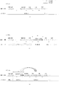
図7(A)はすべてのページを多色モードで形成するケースの紙間を示している。このケースは、たとえば、単色モードおよび当接離間機構を有さない画像形成装置が当てはまる。ここでは1番目のページは両面印刷における1面目であり、単色画像が形成される。2番目のページは両面印刷における2面目であり、単色画像が形成される。3番目のページは片面に単色画像が形成されるページである。4番目と5番目のページはそれぞれ片面に多色画像が形成されるページである。ここでの紙間は二次転写部130における紙間を示している。
<Relationship between paper space and switching time from single color mode to multicolor mode>
FIG. 7A shows the space between papers in a case where all pages are formed in multicolor mode. This case applies, for example, to monochromatic modes and image forming devices that do not have a contact separation mechanism. Here, the first page is the first page in double-sided printing, and a monochromatic image is formed. The second page is the second page in double-sided printing, and a monochromatic image is formed. The third page is a page in which a monochromatic image is formed on one side. The fourth and fifth pages are pages in which a multicolor image is formed on one side, respectively. The paper spacing here indicates the paper spacing in the
多色モードでは多色画像だけでなく、単色画像も形成可能である。画像形成の生産性をあげるために、先行するページと後続のページとの間に生じる紙間は画像形成装置1で実現可能な最小の紙間(通常紙間dn)に設定される。図1を用いて説明したように両面印刷では1面目に画像を形成されたシートPは排紙ローラ153によりスイッチバックして表裏を反転し、両面ユニット170に送り込まれ、さらに、二次転写部130に送り込まれる。したがって、先行するページ(シートPの1面目)の後端が二次転写部130を通過してから、後続のページ(シートPの2面目)の先端が二次転写部130に到着するまでの紙間(処理待ち時間)は通常の紙間dnよりも長い紙間(両面用紙間dm)となる。このように、両面印刷を含むジョブではシートPをスイッチバックするための時間だけ、紙間が長くなる。このケースでは常に多色モードが設定されているため、カラーモードの切り替え時間は発生しないが、感光体ドラム134y〜134cの表面の摩耗が進んでしまう。
In the multicolor mode, not only a multicolor image but also a monochromatic image can be formed. In order to increase the productivity of image formation, the paper spacing generated between the preceding page and the succeeding page is set to the minimum paper spacing (normal paper spacing dn) that can be realized by the
図7(B)は単色画像を単色モードで印刷し、多色画像を多色モードで印刷するケースにおける紙間を示している。図7(B)において各シートに適用される印刷モードは図7(A)に示した印刷モードと同じである。CPU300は、印刷情報400を分析して1番目のページを単色画像が形成されるページであると認識し、単色モードを設定する。CPU300は、印刷情報400を分析して2番目および3番目のページも単色画像が形成されるページであると認識し、単色モードを維持する。CPU300は、印刷情報400を分析して4番目のページを多色画像が形成されるページであると認識し、単色モードから多色モードに切り替える。上述したように単色モードから多色モードへ切り替えるには一定時間が必要となる。したがって、カラーモードの切り替えが実行される3番目のページと4番目のページとの間の紙間が長い紙間(切替紙間dx)になってしまう。つまり、切替紙間dxと通常紙間dnとの差分である紙間doだけ生産性が低下してしまう。
FIG. 7B shows the space between papers in a case where a monochromatic image is printed in a monochromatic mode and a multicolor image is printed in the multicolor mode. The print mode applied to each sheet in FIG. 7 (B) is the same as the print mode shown in FIG. 7 (A). The
ところで、1番目のページと2番目のページとの間の紙間では両面印刷のためのシートPのスイッチバックが実行される。つまり、1番目のページと2番目のページとの間の紙間は通常紙間dnよりも長い両面用紙間dmとなる。本願の発明者は切替紙間dxと両面用紙間dmとに着目した。つまり、発明者は、両面用紙間dmにおいてカラーモードの切り替えを前倒しして実行すれば、生産性が改善されることに気が付いた。つまり、ジョブ全体の紙間の合計値を短縮することが可能となり、生産性が向上する。 By the way, the switchback of the sheet P for double-sided printing is executed between the papers between the first page and the second page. That is, the space between the first page and the second page is a double-sided paper dm longer than the normal paper dn. The inventor of the present application has focused on the switching paper dx and the double-sided paper dm. That is, the inventor has noticed that the productivity can be improved by executing the color mode switching ahead of schedule in the double-sided paper dm. That is, it is possible to shorten the total value between the papers of the entire job, and the productivity is improved.
図7(C)は改善された紙間を示している。図7(C)が示すように、単色モードから多色モードへの切り替えが、通常紙間dnよりも相対的に長い紙間(両面用紙間dm)において実行される。なお、切替紙間dxは両面用紙間dmよりも長いため、両面用紙間dmが切替紙間dxへと拡張される。図7(C)と図7(B)を比較すると分かるように、生産性の低下の目安である紙間doは、切替紙間dxと両面用紙間dmとの差分である紙間dpまで削減される。つまり、図7(C)では両面用紙間dmと通常紙間dnとの差分に相当する時間だけ早く画像形成が完了する。 FIG. 7C shows the improved paper spacing. As shown in FIG. 7C, switching from the monochromatic mode to the multicolor mode is performed in a paper spacing (double-sided paper spacing dm) that is relatively longer than the normal paper spacing dn. Since the switching paper dx is longer than the double-sided paper dm, the double-sided paper dm is extended to the switching paper dx. As can be seen by comparing FIGS. 7 (C) and 7 (B), the inter-paper do, which is a measure of the decrease in productivity, is reduced to the inter-paper dp, which is the difference between the switching inter-paper dx and the double-sided inter-paper dm. Will be done. That is, in FIG. 7C, image formation is completed earlier by a time corresponding to the difference between the double-sided paper dm and the normal paper dn.
なお、多色画像を形成するタイミングからあまりにも早いタイミングで単色モードから多色モードに切り替えてしまうと、Y・M・C用の感光体ドラム134の寿命が短くなってしまう。したがって、多色画像よりも前に連続して形成された単色画像の数が閾値以下となる期間内に相対的に長い紙間がある場合に限って、単色モードから多色モードへの前倒し切り替えが実行されてもよい。たとえば、CPU300は、印刷情報400を解析し、多色画像の前に連続して存在する単色画像の数nをカウントし、単色画像の数nが閾値以下どうかを判定する。単色画像の数nが閾値以下であれば、CPU300は、n個の単色画像が連続する区間における各紙間を調査し、相対的に長い紙間を特定する。そして、CPU300は、相対的に長い紙間においてカラーモードの切り替えを実行する。相対的に長い紙間が存在しなければ、感光体ドラム134の摩耗を軽減すべく、単色画像と多色画像との間の紙間においてカラーモードの切り替えを実行してもよい。
If the monochromatic mode is switched to the multicolor mode too early from the timing of forming the multicolor image, the life of the
<多色モードから単色モードへの切り替え時間と紙間との関係>
図7(A)ないし図7(C)では単色モードから多色モードへ切り替えるケースが着目されているが、多色モードから単色モードへ切り替えるケースにおいても生産性が改善される余地がある。図8(A)はすべてのページを多色モードで形成するケースの紙間を示している。このケースは、たとえば、単色モードおよび当接離間機構を有さない画像形成装置が当てはまる。ここでは1番目のページは片面に多色画像が形成されるシートである。2番目のページは片面に多色画像を形成されるシートである。3番目のページは両面印刷における1面目であり、単色画像を形成される。4番目のページは両面印刷における2面目であり、単色画像を形成される。5番目のページは片面に多色画像を形成されるシートである。
<Relationship between paper space and switching time from multi-color mode to single-color mode>
In FIGS. 7A to 7C, attention is paid to the case of switching from the monochromatic mode to the multicolor mode, but there is room for improvement in productivity even in the case of switching from the multicolor mode to the monochromatic mode. FIG. 8A shows the space between papers in a case where all pages are formed in multicolor mode. This case applies, for example, to monochromatic modes and image forming devices that do not have a contact separation mechanism. Here, the first page is a sheet on which a multicolor image is formed on one side. The second page is a sheet on which a multicolor image is formed on one side. The third page is the first page in double-sided printing and forms a monochromatic image. The fourth page is the second side in double-sided printing and forms a monochromatic image. The fifth page is a sheet on which a multicolor image is formed on one side.
上述したように、多色モードでは多色画像だけでなく、単色画像も形成可能である。したがって、単色画像と多色画像とが混在したジョブが投入されるとCPU300は常に多色モードを維持し、紙間を通常紙間dnに設定してもよい。図8(A)に示したケースでは常に多色モードが設定されているため、カラーモードの切り替え時間は発生しないが、感光体ドラム134y〜134cの表面の摩耗が進んでしまう。
As described above, in the multicolor mode, not only a multicolor image but also a monochromatic image can be formed. Therefore, when a job in which a single color image and a multicolor image are mixed is input, the
図8(B)は感光体ドラム134y〜134cの表面の摩耗を低減するために、多色画像と単色画像との紙間において多色モードから単色モードへの切り替えが実行されるケースを示している。多色モードから単色モードへの切り替えを実行するには切り替え時間が必要となる。つまり、紙間は通常紙間dnよりも長い切替紙間dxへ延長されてしまう。ここでも、切替紙間dxと通常紙間dnとの差分doだけ生産性が低下してしまう。
FIG. 8B shows a case where switching from the multicolor mode to the monochromatic mode is executed between the papers of the multicolor image and the monochromatic image in order to reduce the wear on the surfaces of the
ここで、本願の発明者は、多色画像の後ろに複数の単色画像が連続しており、かつ、両面印刷のための両面用紙間dmも存在することに着目した。つまり、発明者は、多色モードから単色モードへの切り替えを先送りして、両面用紙間dmにおいて切り替えを実行すれば、生産性が改善されることに気が付いた。これにより、ジョブ全体の紙間の合計値を短縮することが可能となる。 Here, the inventor of the present application has noted that a plurality of monochromatic images are continuous after the multicolor image, and that there is also a dm between double-sided papers for double-sided printing. That is, the inventor has noticed that productivity can be improved by deferring the switch from the multicolor mode to the monochromatic mode and executing the switch at the dm between the double-sided papers. This makes it possible to reduce the total value between papers for the entire job.
図8(C)は改善された紙間を示している。図8(C)が示すように、多色モードから単色モードへの切り替えが、通常紙間dnよりも相対的に長い紙間(両面用紙間dm)において実行される。図8(C)と図8(B)を比較すると分かるように、生産性の低下の目安である紙間doは、切替紙間dxと両面用紙間dmとの差分である紙間dpまで削減される。つまり、図8(C)では両面用紙間dmと通常紙間dnとの差分に相当する時間だけ早く画像形成が完了する。 FIG. 8C shows the improved paper spacing. As shown in FIG. 8C, switching from the multicolor mode to the monochromatic mode is performed in a paper spacing (double-sided paper spacing dm) that is relatively longer than the normal paper spacing dn. As can be seen by comparing FIGS. 8 (C) and 8 (B), the inter-paper do, which is a measure of the decrease in productivity, is reduced to the inter-paper dp, which is the difference between the switching inter-paper dx and the double-sided inter-paper dm. Will be done. That is, in FIG. 8C, the image formation is completed earlier by the time corresponding to the difference between the double-sided paper dm and the normal paper dn.
なお、最初に単色画像を形成するタイミングからあまりにも遅いタイミングで多色モードから単色モードに切り替えてしまうと、Y・M・C用の感光体ドラム134の寿命が短くなってしまう。したがって、多色画像の後に連続して形成される単色画像の数が閾値以上となる場合には相対的に長い紙間を探索して、相対的に長い紙間で多色モードから単色モードへの先送り切り替えが実行されてもよい。たとえば、CPU300は、印刷情報400を解析し、多色画像の後に連続して存在する単色画像の数nをカウントし、単色画像の数nが閾値以上どうかを判定する。単色画像の数nが閾値th以上であれば、CPU300は、多色画像に続く区間であってth個の単色画像が連続する区間における各紙間を調査し、相対的に長い紙間を特定する。そして、CPU300は、相対的に長い紙間においてカラーモードの切り替えを実行する。相対的に長い紙間が存在しなければ、感光体ドラム134の摩耗を軽減すべく、多色画像と単色画像との間の紙間においてカラーモードの切り替えを実行してもよい。
If the multicolor mode is switched to the monochromatic mode at a timing that is too late from the timing at which the monochromatic image is first formed, the life of the
<カラーモード切替のフローチャート>
図9はCPU300が実行するカラーモードの切替処理を示すフローチャートである。CPU300は制御プログラムにしたがって以下の処理を実行する。
<Flowchart for switching color modes>
FIG. 9 is a flowchart showing a color mode switching process executed by the
S1でCPU300は印刷情報400をRAM302から読み出して解析する。たとえば、CPU300は、各ページの印刷情報400に含まれている画像データに基づき各ページに形成される画像が多色画像か単色画像かを識別する。あるいは、CPU300は各ページの印刷情報400に含まれている指示(多色画像を形成するか、単色画像を形成するかを示す指示)にしたがって各ページに形成される画像が多色画像か単色画像かを識別してもよい。
In S1, the
S2でCPU300は解析結果に基づき多色画像の前または後ろに複数の単色画像が存在するかどうかを判定する。なお、単色画像だけを形成するジョブが投入されると、CPU300は当接離間機構に単色モードを設定する(離間を指示する)。また、多色画像だけを形成するジョブが投入されると、CPU300は当接離間機構に多色モードを設定する(当接を指示する)。多色画像の前または後ろに複数の単色画像が存在しなければ、CPU300は、多色画像と単色画像との間の紙間でカラーモードを切り替える。一方で、多色画像の前または後ろに複数の単色画像が存在すれば、CPU300は、S3に進む。なお、図7(C)に示したように、多色画像の前に複数の単色画像が存在することがある。また、図8(C)に示したように、多色画像の後ろに複数の単色画像が存在することもある。
In S2, the
S3でCPU300は印刷情報400を解析し、複数の単色画像が連続した区間における各紙間の長さを決定する。たとえば、印刷情報400において両面印刷が指定されていれば、CPU300は1面目のページと2面目のページとの間の紙間を両面用紙間dmに決定する。また、CPU300は、片面画像が形成されるページと片面画像が形成されるページとの間の紙間を通常紙間dnに決定する。たとえば、CPU300は、印刷情報400により給紙カセット100が給紙口として指定されているページの前の紙間を通常紙間dnに決定する。また、CPU300は、印刷情報400により両面ユニット170が給紙口として指定されているページの前の紙間を両面用紙間dmに決定する。
In S3, the
S4でCPU300は複数の単色画像が連続した区間における各紙間において相対的に長い紙間を特定する。たとえば、両面用紙間dmが適用される紙間が存在すれば、CPU300はその紙間を相対的に長い紙間と特定する。図7(C)に示したケースでは1番目のページと2番目のページとの間にある紙間が相対的に長い紙間に特定される。なお、CPU300は元の紙間である両面用紙間dmよりも切替紙間dxが長いため、両面用紙間dmを切替紙間dxに拡張または延長する。図8(C)に示したケースでは3番目のページと4番目のページとの間にある紙間が相対的に長い紙間に特定される。この場合も、両面用紙間dmは切替紙間dxに拡張または延長される。なお、特定された紙間が切替紙間dxよりも長ければ、紙間の延長は不要である。
In S4, the
S5でCPU300は特定された紙間でカラーモードの切り替えを実行する。図7(C)に示したケースでは1番目のページと2番目のページとの間にある紙間でカラーモードを単色モードから多色モードへ切り替える(前倒し切り替え)。図8(C)に示したケースでは3番目のページと4番目のページとの間にある紙間でカラーモードを多色モードから単色モードへ切り替える(先送り切り替え)。
In S5, the
このように本実施例ではカラーモードの切り替えが相対的に長い紙間で実行されるよう、多色モードから単色モードへ切り替えるタイミングが先送りされたり、単色モードから多色モードへ切り替えるタイミングが前倒しされたりする。たとえば、カラーモードの切り替えが実行されるべきタイミングの前に相対的に長い処理待ち時間(紙間)が存在すれば、カラーモードの切り替えが前倒しされる。一方、カラーモードの切り替えが実行されるべきタイミングの後に相対的に長い処理待ち時間(紙間)が存在すれば、カラーモードの切り替えが先送りされる。これにより、単色画像と多色画像とが混在する画像形成ジョブにおける生産性が向上する。 As described above, in this embodiment, the timing of switching from the multicolor mode to the monochromatic mode is postponed, or the timing of switching from the monochromatic mode to the multicolor mode is advanced so that the color mode switching is executed between relatively long papers. Or something. For example, if there is a relatively long processing wait time (between papers) before the timing when the color mode switching should be executed, the color mode switching is advanced. On the other hand, if there is a relatively long processing waiting time (between papers) after the timing at which the color mode switching should be executed, the color mode switching is postponed. This improves productivity in an image forming job in which a single color image and a multicolor image are mixed.
<前倒し切り替えに関するより詳細なフローチャート>
まず、図7(C)を用いて説明された前倒し切り替えが説明される。図10は前倒し切り替えに関するより詳細なフローチャートである。ユーザが外部機器310から画像形成装置1に印刷を指示すると、CPU300は外部機器310から印刷情報400を受信する。
<More detailed flow chart for moving forward>
First, the forward switching described with reference to FIG. 7C will be described. FIG. 10 is a more detailed flowchart regarding the advance switching. When the user instructs the
S11でCPU300は、外部機器310から受信した印刷情報400をRAM302へ記憶する。以降、CPU300は、必要に応じて、RAM302から印刷情報400を読み出して使用する。S12でCPU300は初期化処理として、禁止カウンタに0をセットする。禁止カウンタとは、カラーモードの切り替えを禁止するためにRAM302に確保されるカウンタである。0はカラーモードの切り替えを許容することを示し、0以外の値はカラーモードの切り替えを禁止することを示す。
In S11, the
S13でCPU300は禁止カウンタに基づきカラーモードの切り替えが禁止されているかどうかを判定する。CPU300は、禁止カウンタが0であれば、切り替えが許容されていると判定し、S14に進む。S14でCPU300は必要に応じて切り替え処理を実行する。たとえば、CPU300は、1ページ毎に、多色モードと単色モードのどちらで画像を形成するかを判定する。CPU300は、この判定結果に基づき必要に応じてカラーモードを切り替え、S16に進む。この切り替え処理の詳細は後述する。一方、CPU300は禁止カウンタが0でなければ、切り替えが禁止されていると判定し、S15に進む。S15でCPU300は禁止カウンタから1を減算して、S16に進む。
In S13, the
S16でCPU300は、印刷情報400の給紙口情報402により指定された給紙口からシートPを給紙する。S17でCPU300は画像形成部132を制御し、印刷情報400の画像データにより指定された画像をシートPに形成する。S18でCPU300は印刷情報400の排紙口情報403により指定された排紙口へシートPを排紙する。
In S16, the
S19で、CPU300は、受信した印刷情報400に基づき画像形成ジョブが完了したかどうかを判定する。すべての印刷情報400について画像形成が完了すれば、CPU300は、ジョブが完了したと判定し、画像形成処理を終了する。一方、ジョブが完了していなければ、CPU300はS13に戻り、次のページの画像形成を実行する。
In S19, the
図11は禁止カウンタの作用を示すタイミングチャートである。ここでは、印刷ページ順、カラーモード、禁止カウンタ、切り替えの実行状況が示されている。なお、図11において印刷ページ順とカラーモードについては図7(C)に示したものと同じものが想定されている。CPU300は、印刷情報400を解析することで、単色画像が印刷される複数のページの後に多色画像が印刷されるページがあることを認識する。また、CPU300は、多色画像が印刷されるページの前に存在する単色画像が印刷されるページの数をカウントする。たとえば、すでに1番目のページの印刷が終了していれば、CPU300は、単色画像の連続数nを2と決定する。なお、1番目のページを印刷する前にカウントを実行する場合、CPU300は、単色画像の連続数nを3と決定する。
FIG. 11 is a timing chart showing the operation of the prohibition counter. Here, the print page order, color mode, prohibition counter, and switching execution status are shown. In FIG. 11, the print page order and the color mode are assumed to be the same as those shown in FIG. 7 (C). By analyzing the
次に、CPU300は、単色画像の連続数nが閾値th以下であるかどうかを判定する。ここでは閾値thを2と仮定する。つまり、1番目のページの印刷が終了すると、連続数nが閾値th以下となる。CPU300は、単色画像が形成される3番目のページと多色画像が形成される4番目のページとの間の紙間(通常紙間dn)よりも相対的に長い紙間が存在するかどうかを探索する。CPU300は、1番目のページと2番目のページとの間にある紙間は両面用紙間dmであるため、3番目のページと4番目のページとの間にある通常紙間dnよりも長いと判定する。なお、1番目のページと2番目のページとの間にある紙間のように、単色画像が形成される複数のページのうち先頭ページと、その前のページとの間の紙間は単色先頭紙間とよばれてもよい。単色画像が形成される複数のページのうち最終ページと、その後ろのページとの間の紙間は単色最終紙間と呼ばれてもよい。CPU300は、単色先頭紙間が単色最終紙間よりも相対的に長いため、単色モードから多色モードへの切り替えタイミングを単色先頭紙間に前倒しすると決定する。
Next, the
ここで、単色モードから多色モードへの切り替えタイミングを前倒すると、CPU300は、2番目のページから4番目のページまで多色モードで単色画像を形成しなければならない。一般に、CPU300は、多色モードで動作しているときに単色画像の印刷情報400を発見すると、単色モードへ切り替えようとする。したがって、CPU300は、2番目のページから4番目のページまでは多色モードから単色モードへの切り替えを禁止しなければならない。そこで、本実施例ではカラーモードの切り替え処理を禁止する回数(ページ数)を管理する禁止カウンタが導入されてもよい。図11に示したケースでは、多色モードへの切り替えタイミングが2ページ分だけ前倒しされる。そのため、CPU300は禁止カウンタに2をセットする。CPU300は単色画像を形成するたびに禁止カウンタから1を減算する。図11が示すように、2番目のページへの画像形成が終了すると、CPU300は禁止カウンタの値から1を減算する。3番目のページへの画像形成が終了すると、CPU300は禁止カウンタの値から1を減算する。これにより、3番目のページへの画像形成が終了した時点では禁止カウンタの値が0になる。CPU300は、禁止カウンタに0以外の値がセットされている場合には、カラーモードの切り替えが禁止されていると認識する。CPU300は、禁止カウンタに0がセットされている場合には、カラーモードの切り替えが許可されていると認識する。5番目のページには多色画像が形成されるが、カラーモードはすでに多色モードに設定されているため、カラーモードの切り替えは実行されない。
Here, if the timing of switching from the single color mode to the multicolor mode is advanced, the
●切り替え処理の詳細
図12は図10に示したS14の切り替え処理をより詳細に示している。なお、図10はメインルーチンに相当し、図12はサブルーチンに相当する。カラーモードの切り替えは、多色モードと単色モードのどちらを適用すべきかを決定し、決定結果に応じてカラーモードを切り替える処理である。CPU300は、S13で禁止カウンタを参照し、切り替えが禁止されていないことを認識すると、以下の処理を実行する。
● Details of the switching process FIG. 12 shows the switching process of S14 shown in FIG. 10 in more detail. Note that FIG. 10 corresponds to the main routine, and FIG. 12 corresponds to the subroutine. The color mode switching is a process of deciding whether to apply the multicolor mode or the monochromatic mode, and switching the color mode according to the decision result. When the
S21で、CPU300は、次のページが多色画像かどうかを判定する。たとえば、CPU300は、RAM302に記憶されている印刷情報400を参照し、印刷情報400に含まれている画像データ404が多色画像のデータであるかどうかを判定する。次のページが単色画像であれば、CPU300はS24に進む。S24でCPU300は現在モードが多色モードであるかどうかを判定する。現在モードとは判定処理を実行する時点で画像形成装置1に設定されているカラーモードのことである。現在モードが多色モードであれば、CPU300はS25に進む。S25で、CPU300は、単色モードへ切り替え、メインルーチンにリターンする。
In S21, the
一方で、S21で次のページが単色画像であると判定し、かつ、S22で現在モードが単色モードであると判定すると、CPU300はS26に進む。S26でCPU300はRAM302に記憶されている印刷情報400を参照し、単色画像の後に多色画像が存在するかどうかを判定する。単色画像の後に多色画像が存在していれば、CPU300はS27に進む。CPU300は、単色画像の後に多色画像が存在しなければ、メインルーチンにリターンする。
On the other hand, if it is determined in S21 that the next page is a monochromatic image and in S22 it is determined that the current mode is the monochromatic mode, the
S27でCPU300は多色画像の前に連続的に存在する単色画像の数(連続数n)をカウントする。S28でCPU300は連続数nが閾値以下であるかどうかを判定する。たとえば、閾値thが2ページであり、かつ、単色画像の連続n数が2ページ以下であれば、CPU300はS29に進む。CPU300は、連続数nが閾値th以下でなければ、メインルーチンにリターンする。
In S27, the
S29でCPU300は前倒し判定を実行する。前倒し判定とは、単色モードから多色モードへの切り替えを本来のタイミングよりも前倒しして実行すべきかどうかを判定する処理である。本来のタイミングとは先行する単色画像と後続の多色画像との間の紙間のことである。たとえば、多色モードへの切り替えを前倒すと判定すると、CPU300は禁止カウンタにカラーモードの切り替えを禁止する回数をセットして、S30に進む。なお、S29の詳細は後述される。S30でCPU300は、禁止カウンタに基づき長い紙間が見つかったかどうかを判定する。たとえば、CPU300は、RAM302に記憶されている禁止カウンタの値を参照し、禁止カウンタの値が0かどうかを判定する。ここで、禁止カウンタに0がセットされていれば、CPU300は、相対的に長い紙間が発見されなかったと認識し、メインルーチンにリターンする。つまり、前倒し切り替えは実行されない。一方で、禁止カウンタに0以外の値が設定されていれば、CPU300は、相対的に長い紙間が発見されたと認識し、単色モードから多色モードへの切り替えを前倒しすべく、S23に進む。S23でCPU300はカラーモードを単色モードから多色モードへ切り替え、メインルーチンにリターンする。なお、メインルーチンのS13において禁止カウンタに0以外の値が設定されている判定されると、CPU300はS14に進まない。つまり、図11に示したように多色モードから単色モードへの復帰が禁止される。
In S29, the
なお、S21で次のページが多色画像であると判定すると、CPU300はS22に進む。S22でCPU300は、現在モードが単色モードであるかどうかを判定する。現在モードが多色モードであれば、カラーモードの切り替えは必要無いため、CPU300は、メインルーチンに戻る。一方で、現在モードが単色モードであれば、CPU300はS23に進む。S23でCPU300はカラーモードを単色モードから多色モードへ切り替え、メインルーチンにリターンする。
If it is determined in S21 that the next page is a multicolor image, the
●前倒し判断の詳細
図13は図12に示したS29の前倒し判定を詳細に示すフローチャートである。前倒し判定は、単色モードから多色モードへの切り替えを前倒すための長い紙間を探索し、長い紙間が発見されると禁止カウンタに単色画像の連続数をセットする処理である。
● Details of Advance Determination FIG. 13 is a flowchart showing in detail the advance determination of S29 shown in FIG. The advance determination is a process of searching for a long paper space for advancing the switching from the single color mode to the multi-color mode, and setting the continuous number of single color images in the prohibition counter when a long paper space is found.
S31でCPU300は、先頭ページの給紙口が両面ユニット170であるかどうかを判定する。先頭ページとは、連続して単色画像が形成される複数のページのうちの先頭のページである。たとえば、CPU300は、連続した複数の単色画像のうち先頭の単色画像の印刷情報400の給紙口情報402を参照し、給紙口として両面ユニット170が指定されているかどうかを判定する。なお、先頭の単色画像とは先頭ページに形成される単色画像である。両面ユニット170から給紙されるシートPは、2面目に画像が形成されるシートであり、表裏の反転のために長い処理待ち時間を発生させる。つまり、先頭ページの前には相対的に長い紙間(両面用紙間dm)が発生する。給紙口として両面ユニット170が指定されていれば、CPU300はS33に進む。S33でCPU300は先頭の単色画像(先頭ページ)の前に存在する紙間(先頭紙間dl)に両面用紙間dmをセットする。先頭紙間dlはRAM302に保持されてもよい。S31で給紙口として両面ユニット170が指定されている判定すると、CPU300はS32に進む。S32でCPU300は先頭紙間dlに通常紙間dnをセットする。
In S31, the
S34でCPU300は最終ページの排紙口が両面ユニット170であるかどうかを判定する。最終ページとは、連続して単色画像が形成される複数のページのうちの最後のページである。たとえば、CPU300は、連続した複数の単色画像のうち最後の単色画像の印刷情報400の排紙口情報403を参照し、排紙口として両面ユニット170が指定されているかどうかを判定する。なお、最後の単色画像とは最終ページに形成される単色画像のことである。最終ページの排紙口が両面ユニット170であれば、CPU300はS36に進む。S36でCPU300は最終紙間dtに両面用紙間dmをセットする。最終紙間dtとは最終ページの後ろ(最後の単色画像と多色画像との間)に存在する紙間のことである。S34で最終ページの排紙口が両面ユニット170でないと判定すると、CPU300はS35に進む。S35でCPU300は最終紙間dtに通常紙間dnをセットする。
In S34, the
S34でCPU300は先頭紙間dlが最終紙間dtより長いかどうかを判定する。先頭紙間dlが最終紙間dtより長くなければ、先頭紙間dlにおいて前倒し切り替えを実行すべきでないため、禁止カウンタの値を変更せずに、CPU300は元のルーチンに戻り、元のルーチンのS30に進む。たとえば、先頭紙間dlと最終紙間dtと両方が通常紙間dnであるか、または、両面用紙間dmであれば、先頭紙間dlは最終紙間dtより長くはない。また、先頭紙間dlが通常紙間dnであり、かつ、最終紙間dtが両面用紙間dmであれば、やはり、先頭紙間dlは最終紙間dtより長くはない。一方で、先頭紙間dlが最終紙間dtより長ければ、先頭紙間dlにおいて前倒し切り替えを実行することで生産性が向上する。よって、CPU300はS38に進む。なお、このケースは、先頭紙間dlが両面用紙間dmであり、かつ、最終紙間dtが通常紙間dnでるケースである。S38でCPU300は、禁止カウンタに単色画像の連続数nをセットし、元のルーチンのS30に進む。連続数nは元のルーチンのS27で取得されたカウント値である。
In S34, the
本実施例によれば単色モードから多色モードへの切り替えを前倒しすることで、生産性が向上する。たとえば、多色画像の前に複数の単色画像が連続し、かつ、複数の単色画像が連続している区間に存在する紙間の一つが多色画像と単色画像との間にある紙間よりも長いことがある。複数の単色画像が連続している区間において両面印刷が実行されると、シートPの表裏を反転するために一部の紙間が長くなる。よって、このような相対的に長い紙間でカラーモードの切り替えを実行することで、ジョブの全体で見れば、生産性が向上する。図11では閾値thが2ページである事例が示されている。しかし、これは本発明を限定するものではない。閾値thに大きな値を設定すると、長い紙間が見つかりやすくなるが、前倒しされるページ(単色画像)の数が増加する。つまり、多色モードで形成される単色画像が多くなり、Y・M・Cの感光体ドラム134の摩耗が増えてしまう。一方で、閾値thに小さな値を設定すると、長い紙間が見つかりにくくなり、前倒しされるページ(単色画像)の数が減少する。つまり、生産性の向上が図れないケースも発生するが、Y・M・Cの感光体ドラム134の摩耗は減る。このように、閾値thは生産性とY・M・Cの感光体ドラム134の摩耗とのトレードオフとなる。よって、閾値thは、生産性とY・M・Cの感光体ドラム134の摩耗とバランスが図られるような値に設定されよう。
According to this embodiment, the productivity is improved by accelerating the switching from the monochromatic mode to the multicolor mode. For example, one of the spaces between papers existing in a section in which a plurality of monochromatic images are continuous in front of the multicolor image and the plurality of monochromatic images are continuous is more than a space between papers between the multicolor image and the monochromatic image. Can also be long. When double-sided printing is executed in a section in which a plurality of monochrome images are continuous, a part of the paper space becomes long because the front and back sides of the sheet P are reversed. Therefore, by switching the color mode between such relatively long papers, the productivity of the entire job is improved. FIG. 11 shows an example in which the threshold value th is
<先送り切り替えに関するより詳細なフローチャート>
次に、図8(C)を用いて説明された先送り切り替えが説明される。図14は先送り切り替えに関するより詳細なフローチャートである。なお、図14において図10と共通するステップには同一の参照符号が付与されている。図14と図10の相違点は、S13ないしS15がS40およびS41に置換されている点である。
<More detailed flow chart for postponement switching>
Next, the postponement switching described with reference to FIG. 8C will be described. FIG. 14 is a more detailed flowchart of the postponement switching. In FIG. 14, the same reference numerals are given to the steps common to those in FIG. The difference between FIGS. 14 and 10 is that S13 to S15 are replaced with S40 and S41.
S40でCPU300は初期化処理として、遅延カウンタに0をセットする。遅延カウンタとは、多色モードから単色モードへ切り替えるタイミングを遅らせるために使用されるカウンタであり、RAM302に保持される。S41でCPU300は遅延カウンタに応じて多色モードから単色モードへの切り替えを実行する。
In S40, the
図15は遅延カウンタの作用を示すタイミングチャートである。ここでは、印刷ページ順、カラーモード、遅延カウンタ、切り替えの実行状況が示されている。なお、図15において印刷ページ順とカラーモードについては図8(C)に示したものと同じものが想定されている。 FIG. 15 is a timing chart showing the operation of the delay counter. Here, the print page order, color mode, delay counter, and switching execution status are shown. In FIG. 15, the print page order and the color mode are assumed to be the same as those shown in FIG. 8 (C).
たとえば、CPU300は、多色モードで多色画像を形成しているときに、この多色画像の後に所定数以上の単色画像が連続して存在するかどうかを、印刷情報400に基づき判定する。つまり、単色画像の連続数nが閾値th以上であれば、CPU300は多色モードから単色モードへの切り替えが必要であると判定する。この例では、1個の多色画像の後ろに4個の単色画像が連続している。また、閾値thは3に設定されているものと仮定する。CPU300はth個の単色画像のうちの先頭画像の前に存在している紙間よりも相対的に長い紙間が、先頭画像から最終画像までの間に存在するかどうかを判定する。最終画像とは、th個の単色画像のうちの最後に形成される単色画像のことである。図15において先頭画像は2番目のページに形成された単色画像である。最終画像は4番目のページに形成される単色画像である。多色画像と先頭画像との間にある紙間よりも相対的に長い紙間を発見すると、CPU300は、発見した紙間において多色モードから単色モードへの切り替えを実行する。この例では、多色画像と先頭画像との間にある紙間は通常紙間dnであり、最終画像の前にある紙間は両面用紙間dmである。したがって、CPU300は相対的に長い紙間として3番目のページと4番目のページとの間にある両面用紙間dmを特定する。本来は1番目のページと2番目のページとの間で実行される切り替えが、3番目のページと4番目のページとの間にある紙間で実行される。したがってCPU300は切り替えタイミングを2ページにわたり先送りする(遅延させる)ために、遅延カウンタに2をセットする。CPU300は1ページに画像を形成するたびに遅延カウンタから1を減算する。3番目のページへの画像形成が完了すると、遅延カウンタが0になる。よって、CPU300は、カラーモードの切り替えを実行する。
For example, when a multicolor image is formed in the multicolor mode, the
このようにカラーモードの切り替えが先送り(遅延)される。遅延カウンタは、本来の切り替えタイミングに対して切り替えが遅延されるページの数を示す。遅延カウンタに0以外の値がセットされている場合、CPU300は、切り替えを実行せずに、遅延カウンタの値を一つ削減する。一方で、遅延カウンタの値が0になったタイミングでCPU300は多色モードから単色モードへの切り替えを実行する。
In this way, the color mode switching is postponed (delayed). The delay counter indicates the number of pages whose switching is delayed with respect to the original switching timing. When a value other than 0 is set in the delay counter, the
●切り替え処理の詳細
図16は、図14に示したS41の切り替え処理の詳細を示したフローチャートである。なお、図16に示したサブルーチンは図14に示したメインルーチンから呼び出されるものとする。図14のフローチャートから明らかなように切り替え処理は1ページごとに実行される。
● Details of Switching Process FIG. 16 is a flowchart showing details of the switching process of S41 shown in FIG. It is assumed that the subroutine shown in FIG. 16 is called from the main routine shown in FIG. As is clear from the flowchart of FIG. 14, the switching process is executed page by page.
S51でCPU300は、遅延カウンタの値が0かどうかを判定する。つまり、CPU300は、遅延カウンタに基づき遅延切り替えが予約されているかどうかを判定する。遅延カウンタはRAM302に保持されている。遅延カウンタが0である場合、カラーモードの切り替えが許可されているため、CPU300はS52に進む。S52でCPU300は、次の画像が多色画像かどうかを判定する。たとえば、CPU300は次の印刷対象となっているページの印刷情報400に含まれている画像データ404を参照し、画像データ404が多色画像の画像データであるかどうかを判定する。ここで、次の画像が多色画像である場合、CPU300はS53に進む。S53でCPU300は、現在モードが単色モードであるかどうかを判定する。ここで、現在モードが単色モードである場合、CPU300はS54に進む。S54で、CPU300は単色モードから多色モードへの切り替えを実行し、図14に示したメインルーチンに戻る。
In S51, the
一方、S51で遅延カウンタを0であると判定し、かつ、S52で次の画像を単色画像であると判定すると、CPU300はS56に進む。S56でCPU300は、現在モードが多色モードであるかどうかを判定する。現在モードが単色モードである場合、切り替えは不要であるため、CPU300はメインルーチンに戻る。一方で、現在モードが多色モードである場合、CPU300はS57に進む。
On the other hand, if the delay counter is determined to be 0 in S51 and the next image is determined to be a monochromatic image in S52, the
S57でCPU300は、印刷情報400に基づき、多色画像の後に存在する単色画像の連続数nをカウントする。S58で、CPU300は連続数nが閾値th以上かどうかを判定する。連続数nが閾値th以上でなければ、CPU300は、単色モードへの切り替えを実行せずに、多色モードを継続する。これにより生産性が向上する。よって、連続数nが閾値th以上でなければ、CPU300はメインルーチンに戻る。一方で、連続数nが閾値th以上であれば、CPU300はS59に進む。
In S57, the
なお、連続数nが閾値th以上であれば、CPU300は、多色モードから単色モードへの切り替えが必要であると認識するが、どのタイミングで実行するかが問題となる。そこで、CPU300はS59に進む。S59でCPU300は切り替えタイミングを決定するための先送り判定を実行する。図15を用いて説明したように、先送り判定では、本来の切り替えタイミングである先頭紙間よりも長い紙間が存在するかどうかを探索する処理である。先頭紙間よりも相対的に長い紙間が発見されれば、発見された紙間が切り替えタイミングに決定される。つまり、遅延カウンタには切り替えタイミングを示す値が格納される。図15を用いて説明したように、切り替えタイミングが本来のタイミングから2ページにわたり先送りされる場合、遅延カウンタには2が設定される。なお、S59の詳細は後述される。
If the continuous number n is equal to or higher than the threshold value th, the
S60でCPU300は遅延カウンタの値をRAM302から取得し、遅延カウンタの値が0かどうかを判定することで、単色モードへの切り替えを先送りすべきかどうかを判定する。ここで、遅延カウンタに0以外の値がセットされている場合、CPU300は、単色モードへの切り替えをスキップし、メインルーチンに戻る。一方で、遅延カウンタに0がセットされていれば、CPU300はS61に進む。S61でCPU300は多色モードから単色モードへ切り替える。
In S60, the
ところで、S51で遅延カウンタに0以外の値がセットされていると判定すると、CPU300はS55に進む。このように、遅延カウンタに0以外の値がセットされているケースは、先頭紙間よりも相対的に長い紙間が発見されているものの、その紙間が到来していないケースである。図15では、2番目のページと3番目のページとの間にある紙間がCPU300による処理対象となっているケースである。S55でCPU300は、遅延カウンタの値を1つ減らし、S60に進む。
By the way, if it is determined in S51 that a value other than 0 is set in the delay counter, the
●先送り判定の詳細
図17は、図16に示したS59の先送り判定の詳細を示すフローチャートである。先送り判定は、多色画像と単色画像との間に存在する紙間より相対的に長い紙間を探索する処理である。なお、探索範囲は、多色画像の後に存在する閾値分の単色画像である。なお、多色画像と単色画像との間に存在する紙間は、切り替えが実行されるべき本来の紙間であり、元の紙間と呼ばれる。
● Details of Postponement Determination FIG. 17 is a flowchart showing details of the postponement determination of S59 shown in FIG. The postponement determination is a process of searching for a space between papers that is relatively longer than the space between papers existing between the multicolor image and the monochromatic image. The search range is a single-color image for a threshold value existing after the multicolor image. The space between the papers existing between the multicolor image and the single color image is the original space between the papers on which the switching should be executed, and is called the original space between the papers.
S71でCPU300は初期化処理として、チェックカウンタを0にセットする。先送り判定では、多色モードから単色モードへの切り替えが実行される紙間を特定するための情報が必要となる。たとえば、切り替えが実行される紙間が、元の紙間に対して何ページ分だけ後ろの位置にあるかを示す情報が必要となる。この情報を保持するためにチェックカウンタがRAM302に記憶される。
In S71, the
S72でCPU300はチェックカウンタの値を1つインクリメントする。このように、チェックカウンタは、チェック対象となる紙間を1つ後ろの紙間に移すたびに、カウントアップされる。S73でCPU300は、直前ページの排紙口が両面ユニット170であるかどうかを判定する。直前ページとはチェック対象となっている紙間の直前に存在するページである。図15が示すように、チェック対象の紙間が2番目のページと3番目のページとの間にある紙間であれば、直前ページは2番目のページである。CPU300は、直前ページについての印刷情報400に含まれている排紙口情報403を参照し、排紙口として両面ユニット170が指定されているかどうかを判定する。排紙口情報403が排紙トレイ160を指定している場合、CPU300はS74に進む。S74でCPU300は、チェック対象の紙間に通常紙間dnをセットし、S76に進む。一方で、排紙口情報403が両面ユニット170を指定している場合、CPU300はS75に進む。S75でCPU300は、チェック対象の紙間に両面用紙間dmをセットし、S76に進む。
In S72, the
S76でCPU300はチェック対象の紙間が元の紙間よりも相対的に長いかどうかを判定する。元の紙間が通常紙間であり、チェック対象の紙間も通常紙間であれば、チェック対象の紙間が元の紙間よりも相対的に長くはないため、CPU300はS77に進む。S77でCPU300は、チェックすべき紙間がまだ残っているかどうかを判定する。たとえば、閾値thが3であれば、チェックすべき紙間の数は2である。したがって、チェックの完了した紙間の数が(閾値−1)よりも小さければ、CPU300は、チェックすべき紙間がまだ残っていると判定する。チェックの完了した紙間の数が(閾値−1)に一致していれば、CPU300は、チェックすべき紙間は残っていないと判定する。
In S76, the
一方、S76において、元の紙間が通常紙間であり、チェック対象の紙間が両面用紙間であれば、チェック対象の紙間が元の紙間よりも相対的に長いため、CPU300はS78に進む。S78でCPU300は遅延カウンタにチェックカウンタの値をセットし、元のルーチンに戻る。
On the other hand, in S76, if the original paper spacing is between normal papers and the check target paper spacing is between double-sided papers, the check target paper spacing is relatively longer than the original paper spacing, so the
本実施例によれば多色モードから単色モードへの切り替えを先送りすることで、生産性が向上する。たとえば、多色画像の後に複数の単色画像が連続し、かつ、複数の単色画像が連続している区間に存在する紙間の一つが、多色画像と単色画像との間にある紙間よりも長いことがある。複数の単色画像が連続している区間において両面印刷が実行されると、シートPの表裏を反転するために一部の紙間が長くなる。よって、このような相対的に長い紙間でカラーモードの切り替えを実行することで、印刷ジョブの全体で見れば、生産性が向上する。図15では閾値thが3ページである事例が示されている。しかし、これは本発明を限定するものではない。閾値thに大きな値を設定すると、長い紙間が見つかりやすくなるが、先送りされるページ(単色画像)の数が増加する。つまり、多色モードで形成される単色画像が多くなり、Y・M・Cの感光体ドラム134の摩耗が増えてしまう。一方で、閾値thに小さな値を設定すると、長い紙間が見つかりにくくなり、先送りされるページ(単色画像)の数が減少する。つまり、生産性の向上が図れないケースも発生するが、Y・M・Cの感光体ドラム134の摩耗は減る。このように、閾値thは生産性とY・M・Cの感光体ドラム134の摩耗とのトレードオフとなる。よって、閾値thは、生産性とY・M・Cの感光体ドラム134の摩耗とバランスが図られるような値に設定されよう。
According to this embodiment, the productivity is improved by postponing the switching from the multicolor mode to the monochromatic mode. For example, one of the spaces between papers existing in a section in which a plurality of monochromatic images are continuous after a multicolor image and a plurality of monochromatic images are continuous is more than a space between papers between the multicolor images and the monochromatic images. Can also be long. When double-sided printing is executed in a section in which a plurality of monochrome images are continuous, a part of the paper space becomes long because the front and back sides of the sheet P are reversed. Therefore, by switching the color mode between such relatively long papers, the productivity of the entire print job is improved. FIG. 15 shows an example in which the threshold value th is
<まとめ>
画像形成装置1は単色モードから多色モードへ切り替えや、多色モードから単色モードへ切り替えを長い紙間で実行することで生産性を向上させる。図11などに示したように、画像形成装置1は、多色画像の前に複数の単色画像が形成されるジョブを受信すると、複数の単色画像間に存在するいくつかの紙間のうち相対的に長い紙間を探索する。画像形成装置1は当該相対的に長い紙間までは単色モードで複数の単色画像に含まれる一部の単色画像を順番に形成し、当該相対的に長い紙間において単色モードから多色モードへ切り替える。画像形成装置1は、当該相対的に長い紙間の後は多色モードで複数の単色画像のうち残りの単色画像と多色画像とを順番に形成する。一方で、図15などに示したように、画像形成装置1は、多色画像の後に複数の単色画像が形成されるジョブを受信すると、複数の単色画像間に存在するいくつかの紙間のうち相対的に長い紙間を探索する。画像形成装置1は、当該相対的に長い紙間までは多色モードで多色画像と複数の単色画像に含まれる一部の単色画像を順番に形成し、当該紙間において多色モードから単色モードへ切り替える。その後、画像形成装置1は、当該相対的に長い紙間の後は単色モードで複数の単色画像に含まれる残りの単色画像を順番に形成する。
<Summary>
The
図1を用いて説明したように、画像形成部132kは第一色(例:ブラック)のトナーを用いて画像を形成する第一形成手段の一例である。画像形成部132y、132m、132cは第二色(例:イエロー、マゼンタ、シアン)のトナーを用いて画像を形成する第二形成手段の一例である。中間転写ベルト131は少なくとも画像形成部132kから画像を転写される中間転写体の一例である。当接離間機構333は多色モードと単色モードとを有する当接離間手段の一例である。当接離間機構333は、第二形成手段の像担持体と中間転写体とを当接または離間させる機構である。多色モードとは、画像形成部132kと画像形成部132y、132m、132cとの双方に中間転写ベルト131を当接させるカラーモードである。単色モードとは、画像形成部132kに中間転写ベルト131を当接させたまま画像形成部132y、132m、132cから中間転写ベルト131を離間させるカラーモードである。CPU300は画像形成部132k、132y、132m、132cを制御し、第一色のトナーを用いた画像と第二色のトナーを用いた画像とを重畳した多色画像を形成させるか、または、第一色のトナーのみを用いた単色画像を形成させる制御手段の一例である。CPU300は、多色画像が形成されるページと単色画像が形成されるページとが混在するジョブであって、単色モードから多色モードへの切り替えが必要なジョブを投入されることがある。前倒し切り替えとして説明したように、CPU300は、ジョブにおける先行するページと後続のページとの間の処理待ち時間のうち、相対的に長い処理待ち時間において、単色モードから多色モードへ切り替える。CPU300は、多色画像が形成されるページと単色画像が形成されるページとが混在するジョブであって、多色モードから単色モードへの切り替えが必要なジョブが投入されることがある。先送り切り替えとして説明したように、CPU300は、ジョブにおける先行するページと後続のページとの間の処理待ち時間のうち、相対的に長い処理待ち時間において、多色モードから単色モードへ切り替える。
As described with reference to FIG. 1, the
図18はCPU300が制御プログラムを実行することで実現する機能の一例を示している。CPU300が備える機能の一部またはすべては、ASICやFPGAなどのハードウエアによって実現されてもよい。ASICは特定用途集積回路の略称である。FPGAはフィールドプログラマブルゲートアレイの略称である。
FIG. 18 shows an example of a function realized by the
判別部1801は、ジョブ(印刷情報400)を解析し、各ページ間の処理待ち時間(いわゆる紙間)を判別する。S3やS31、34に関して説明したように給紙口情報402や排紙口情報403を参照し、各ページ間の紙間を決定する。S4やS37に関して説明したように特定部1802は判別部1801の判別結果に基づき相対的に長い処理待ち時間を特定する。このように印刷情報400などのジョブデータを参照することで相対的に長い紙間が特定されてもよい。
The
相対的に長い処理待ち時間は、シートPの両面に画像を形成するために確保される処理待ち時間(例:両面用紙間dm)であってもよい。シートPの1面目に画像を形成した後でシートPの2面目に画像を形成するにはシートPの表裏の反転処理が必要となり、紙間が長くなる。したがって、この紙間においてカラーモードの切り替えを実行すれば、生産性が向上する。なお、相対的に長い紙間の一例として両面用紙間dmが一例として採用されているが、これは一例にすぎない。相対的に長い紙間は他の要因により発生することもある。たとえば、搬送方向と直交する方向における長さ(幅)が短いシートPを連続して定着装置140に通紙すると、定着装置140の端部が中央部よりも昇温してしまう。これは、シートPが定着装置140の中央部のみを通過するからである。このような昇温を抑制するために、このようなサイズの小さいシートPが指定されると、CPU300が紙間を延長することがある。よって、定着装置140の昇温を軽減するために延長された紙間においてカラーモードの切り替えが実行されてもよい。このように相対的に長い処理待ち時間は、定着手段の部分的な昇温を抑制するために確保される処理待ち時間であってもよい。
The relatively long processing waiting time may be a processing waiting time (eg, dm between double-sided papers) secured for forming an image on both sides of the sheet P. In order to form an image on the second surface of the sheet P after forming an image on the first surface of the sheet P, it is necessary to reverse the front and back surfaces of the sheet P, and the space between papers becomes long. Therefore, if the color mode is switched between the papers, the productivity is improved. As an example of relatively long paper spacing, double-sided paper spacing dm is adopted as an example, but this is only an example. The relatively long paper spacing may be caused by other factors. For example, when sheets P having a short length (width) in a direction orthogonal to the transport direction are continuously passed through the fixing
また、画像形成装置1は、色ずれや画像濃度などを補正するために、先行する画像と後続の画像との間の紙間を延長し、中間転写ベルト131上に測定用画像を形成することがある。なお、色ずれは、各色の画像形成位置が理想位置からずれることで発生する。したがって、CPU300は補正処理を実行するために延長した紙間においてカラーモードを切り替えてもよい。つまり、相対的に長い処理待ち時間は、画像形成位置のずれを補正する補正処理を実行するために確保される処理待ち時間であってもよい。また、相対的に長い処理待ち時間は、画像濃度を補正する補正処理を実行するために確保される処理待ち時間であってもよい。
Further, the
また、穿孔、製本処理、ステープル処理などを実行する後処理装置が画像形成装置1に接続されることがある。画像形成装置1は後処理装置においてシートPの受け入れ準備が完了するまでシートPを後処理装置に搬送することができない。つまり、紙間が延長される。このように、CPU300は、後処理装置に起因して延長される紙間において、カラーモードを切り替えてもよい。つまり、相対的に長い処理待ち時間は、後処理装置のために確保される処理待ち時間であってもよい。
In addition, a post-processing device that executes perforation, bookbinding processing, staple processing, and the like may be connected to the
画像形成装置1が複数の給紙口を備えていることがある。CPU300は、給紙口を切り替えるために、紙間が延長することがある。よって、CPU300は、給紙口を切り替えるために延長された紙間においてカラーモードを切り替えてもよい。このように、相対的に長い処理待ち時間は、給紙口を切り替えるために確保される処理待ち時間であってもよい。
The
図7(C)が示すように、CPU300は、相対的に長い処理待ち時間において、単色モードから多色モードへ切り替えることで、ジョブにおける一部のページに多色モードを用いて単色画像を形成する。このように、多色モードにおいて画像形成装置1は多色画像だけでなく、単色画像を形成すること可能である。したがって、本来のタイミングよりも前倒しされたタイミングで単色モードから多色モードへ切り替えることで、生産性が向上する。
As shown in FIG. 7C, the
図11や図12では連続数nを用いて説明したが、実施例の技術思想はさらに一般化されうる。CPU300は、ジョブにおいてi番目のページに多色画像が形成され、i−j番目からi−1番目までの各ページに単色画像が形成され、かつ、i−1番目のページとi番目のページとの間の処理待ち時間よりも、i−j−1番目のページとi−j番目のページとの間の処理待ち時間が相対的に長ければ、i−j−1番目のページとi−j番目のページとの間の処理待ち時間において、単色モードから多色モードへの切り替えを実行する。これにより、i−j番目からi−1番目までの各ページには多色モードを用いて単色画像が形成される。なお、図11に示した事例では、iは4であり、jは2である。つまり、iは連続数nに相当し、jは閾値thに相当する。
Although the continuous number n has been described in FIGS. 11 and 12, the technical idea of the embodiment can be further generalized. In the job, the
図11や図12、図13を用いて説明したように、CPU300の切替制御部1805は、i−j番目のページからi番目のページまでに存在する処理待ち時間においては多色モードから単色モードへの切り替えを禁止する禁止手段として機能してもよい。図11に示した事例では2番目のページから4番目のページまでに存在する2つの紙間ではカラーモードの切り替えが禁止される。切替制御部1805は禁止カウンタ1806を用いることで多色モードから単色モードへの切り替えを禁止してもよい。
As described with reference to FIGS. 11, 12, and 13, the switching
図18やS27が示すように、取得部1803は、i−j番目からi−1番目までのページ数j(連続数n)を取得する。S28に関して説明したように、判定部1804はページ数jが閾値以下であるかどうかを判定する。なお、切替制御部1805はページ数jが閾値以下である場合に、i−j−1番目のページとi−j番目のページとの間の処理待ち時間において、単色モードから多色モードへの切り替えを実行してもよい。つまり、連続した複数の単色画像のうち先頭画像の前に存在する紙間においてカラーモードの切り替えが実行されてもよい。とりわけ、この紙間が相対的に長い紙間であれば、生産性が向上する。一方、切替制御部1805は、ページ数jが閾値以下でない場合に、i−1番目のページとi番目のページとの間の処理待ち時間において、単色モードから多色モードへの切り替えを実行してもよい。つまり、十分に連続した複数の単色画像が存在しない場合、最後の単色画像と多色画像との間にある紙間でカラーモードの切り替えが実行されてもよい。
As shown in FIGS. 18 and S27, the
図8(C)などを用いて説明したように、CPU300は、多色画像が形成されるページと単色画像が形成されるページとが混在するジョブであって、多色モードから単色モードへの切り替えが必要なジョブが投入されることがある。CPU300は、ジョブにおける先行するページと後続のページとの間の処理待ち時間のうち、相対的に長い処理待ち時間において、多色モードから単色モードへ切り替えることで、ジョブにおける一部のページに多色モードを用いて単色画像を形成してもよい。これにより、生産性が向上する。たとえば、図8(C)や図15が示すように多色モードから単色モードへの切り替えが本来のタイミングよりも先送りされて実行されてもよい。
As described with reference to FIG. 8C and the like, the
図8(C)や図15では特定の事例が示されているが、本実施例の技術思想は次のように一般化されうる。ジョブにおいてi番目のページに多色画像が形成され、i+1番目のページからi+k番目のページまでのそれぞれに単色画像が形成されることがある。図8(C)や図15ではi=1かつk=3のケースが示されている。CPU300は、i番目のページとi+1番目のページとの間の処理待ち時間よりも、i+k−1番目のページとi+k番目のページとの間の処理待ち時間が相対的に長ければ、i+k−1番目のページとi+k番目のページとの間の処理待ち時間において、多色モードから単色モードへの切り替えを実行する。この場合、CPU300は、i+1番目のページからi+k−1番目のページまでのそれぞれには多色モードを用いて単色画像を形成する。これにより生産性が向上する。
Although specific cases are shown in FIGS. 8C and 15, the technical idea of this embodiment can be generalized as follows. In a job, a multicolor image may be formed on the i-th page, and a monochromatic image may be formed on each of the i + 1th page to the i + kth page. 8 (C) and 15 show cases of i = 1 and k = 3. The
図15が示すように、CPU300は、i+1番目のページからi+k−1番目のページまでに存在する処理待ち時間においては多色モードから単色モードへの切り替えを禁止する。i+1番目のページからi+k−1番目のページまでは単色画像が形成れるため、通常であれば、単色モードへの切り替えが実行されてしまう。そこで、切替制御部1805は遅延カウンタ1807やチェックカウンタ1808を用いることで、通常紙間dnでの切り替えを禁止し、より長い紙間での切り替えを許可してもよい。
As shown in FIG. 15, the
S57に関して説明したように、取得部1803は、i+1番目からi+k番目までのページ数kを取得する。ここで、kは連続数nに相当する。判定部1804は、ページ数kが閾値以上であるかどうかを判定する。切替制御部1805はページ数kが閾値以上である場合に、i+k−1番目のページとi+k番目のページとの間の処理待ち時間において、多色モードから単色モードへの切り替えを実行する。なお、ページ数kが閾値以上でない場合に、切替制御部1805はi番目のページとi+1番目のページとの間の処理待ち時間において、多色モードから単色モードへの切り替えを実行してもよい。このように、連続数n(ページ数k)が閾値th以上であれば、多色モードで単色画像が形成されることになるため、感光体ドラム134y等の摩耗が進む。したがって、多色モードから単色モードへの切り替えを実行することで、感光体ドラム134y等の寿命が延びる。一方で、連続数n(ページ数k)が閾値th未満であれば、感光体ドラム134y等の摩耗はそれほど進行しない。よって、多色モードから単色モードへの切り替えがスキップされてもよい。
As described with respect to S57, the
図1を用いて説明したように画像形成部132kはブラックのトナーを用いて画像を形成するブラックステーションである。画像形成部132yはイエローのトナーを用いて画像を形成するイエローステーションである。画像形成部132mはマゼンタのトナーを用いて画像を形成するマゼンタステーションである。画像形成部132cはシアンのトナーを用いて画像を形成するシアンステーションである。中間転写ベルト131はブラックステーション、イエローステーション、マゼンタステーションおよびシアンステーションのうちの少なくとも一つから画像を転写される中間転写体である。多色モードは、ブラックステーション、イエローステーション、マゼンタステーションおよびシアンステーションに中間転写ベルト131を当接させるカラーモードである。単色モードは、ブラックステーションにのみ中間転写ベルト131を当接させたままイエローステーション、マゼンタステーションおよびシアンステーションから中間転写ベルト131を離間させるモードである。CPU300は、ブラックステーション、イエローステーション、マゼンタステーションおよびシアンステーションを制御し、ブラックのトナーを用いた画像、イエローのトナーを用いた画像、マゼンタのトナーを用いた画像およびシアンのトナーを用いた画像を重畳した多色画像を形成させるか、または、ブラックのトナーのみを用いた単色画像を形成させる。上記の実施例では、4色のトナーが使用されているが、2色以上のトナーを使用する画像形成装置に対して本発明は適用可能である。
As described with reference to FIG. 1, the
1…画像形成装置、131…中間転写ベルト、132y〜132k…画像形成部、200…CPU、333…当接離間機構、 1 ... Image forming apparatus, 131 ... Intermediate transfer belt, 132y to 132k ... Image forming unit, 200 ... CPU, 333 ... Contact separation mechanism,
Claims (17)
第二色のトナーを用いて第二感光体に画像を形成する第二形成手段と、
前記第一形成手段により前記第一感光体に形成された画像および前記第二形成手段により前記第二感光体に形成された画像が転写される中間転写体と、
前記第一感光体と前記第二感光体との双方に前記中間転写体が当接している状態で画像が形成される多色モードと、前記第一感光体に前記中間転写体が当接し前記第二感光体から前記中間転写体が離間している状態で画像が形成される単色モードとに変位させる当接離間手段と、
前記第一形成手段および前記第二形成手段を制御し、前記第一色のトナーを用いた画像と前記第二色のトナーを用いた画像とを重畳した多色画像を形成させるか、または、前記第二色のトナーを使用せずに前記第一色のトナーを用いた単色画像を形成させる制御手段と、を有し、
前記制御手段は、
前記多色画像が形成されるページと前記単色画像が形成されるページとが混在するジョブが投入され、前記ジョブの途中で前記単色モードから前記多色モードへの切り替えを行う場合に、前記ジョブを解析することにより、前記ジョブにおける前記多色画像が形成されるページよりも前の複数のページにおいて隣り合うページ間の処理待ち時間を判別し、各ページ間の処理待ち時間のうち相対的に長い処理待ち時間を特定し、特定された相対的に長い処理待ち時間が前記多色モードと前記単色モードとの切り替えに要する時間よりも短くても、当該相対的に長い処理待ち時間において、前記単色モードから前記多色モードへ切り替えることを特徴とする画像形成装置。 The first forming means for forming an image on the first photoconductor using the first color toner,
A second forming means for forming an image on the second photoconductor using a second color toner,
An intermediate transfer body to which an image formed on the first photoconductor by the first forming means and an image formed on the second photoconductor by the second forming means are transferred.
A multicolor mode in which an image is formed with the intermediate transfer body in contact with both the first photoconductor and the second photoconductor, and the intermediate transfer body in contact with the first photoconductor. A contact separating means for displacing the intermediate transfer body from the second photoconductor into a monochromatic mode in which an image is formed while the intermediate transfer body is separated from the second photoconductor.
The first forming means and the second forming means are controlled to form a multicolor image in which an image using the first color toner and an image using the second color toner are superimposed. It has a control means for forming a monochromatic image using the first color toner without using the second color toner.
The control means
The multi-color image is a job in which the pages are mixed to the monochromatic image and the page to be formed is formed is turned, in the case of switching from the single-color mode in the middle of the job to the multi-color mode, the job By analyzing, the processing waiting time between adjacent pages on a plurality of pages before the page on which the multicolor image is formed in the job is determined, and the processing waiting time between each page is relatively. In the relatively long processing waiting time, even if a long processing waiting time is specified and the specified relatively long processing waiting time is shorter than the time required for switching between the multicolor mode and the monochromatic mode, the said An image forming apparatus characterized by switching from a single color mode to the multicolor mode.
第二色のトナーを用いて第二感光体に画像を形成する第二形成手段と、
前記第一形成手段により前記第一感光体に形成された画像および前記第二形成手段により前記第二感光体に形成された画像が転写される中間転写体と、
前記第一感光体と前記第二感光体との双方に前記中間転写体が当接している状態で画像が形成される多色モードと、前記第一感光体に前記中間転写体が当接し前記第二感光体から前記中間転写体が離間している状態で画像が形成される単色モードとを有する当接離間手段と、
前記第一形成手段および前記第二形成手段を制御し、前記第一色のトナーを用いた画像と前記第二色のトナーを用いた画像とを重畳した多色画像を形成させるか、または、前記第二色のトナーを使用せずに前記第一色のトナーを用いた単色画像を形成させる制御手段と、を有し、
前記制御手段は、
前記多色画像が形成されるページと前記単色画像が形成されるページとが混在するジョブが投入され、前記ジョブの途中で前記多色モードから前記単色モードへの切り替えを行う場合に、前記ジョブを解析することにより、前記ジョブにおける前記多色画像が形成されるページの後の複数のページにおいて隣り合うページ間の処理待ち時間を判別し、各ページ間の処理待ち時間のうち相対的に長い処理待ち時間を特定し、特定された相対的に長い処理待ち時間が前記多色モードと前記単色モードとの切り替えに要する時間よりも短くても、当該相対的に長い処理待ち時間において、前記多色モードから前記単色モードへ切り替えることを特徴とする画像形成装置。 The first forming means for forming an image on the first photoconductor using the first color toner,
A second forming means for forming an image on the second photoconductor using a second color toner,
An intermediate transfer body to which an image formed on the first photoconductor by the first forming means and an image formed on the second photoconductor by the second forming means are transferred.
A multicolor mode in which an image is formed with the intermediate transfer body in contact with both the first photoconductor and the second photoconductor, and the intermediate transfer body in contact with the first photoconductor. A contact separating means having a monochromatic mode in which an image is formed in a state where the intermediate transfer body is separated from the second photoconductor, and
The first forming means and the second forming means are controlled to form a multicolor image in which an image using the first color toner and an image using the second color toner are superimposed. It has a control means for forming a monochromatic image using the first color toner without using the second color toner.
The control means
The multi-color image is a job in which the pages are mixed to the monochromatic image and the page to be formed is formed is turned, when performing switching from the multi-color mode in the middle of the job to the monochromatic mode, the job By analyzing, the processing waiting time between adjacent pages in a plurality of pages after the page on which the multicolor image is formed in the job is determined, and the processing waiting time between each page is relatively long. The processing wait time is specified, and even if the specified relatively long processing waiting time is shorter than the time required for switching between the multicolor mode and the monochromatic mode, in the relatively long processing waiting time, the many An image forming apparatus characterized by switching from a color mode to the monochromatic mode.
前記相対的に長い処理待ち時間は、前記定着手段の部分的な昇温を抑制するために確保される処理待ち時間であることを特徴とする請求項1または2に記載の画像形成装置。 Further having a fixing means for fixing the image transferred from the intermediate transfer body on the sheet,
The image forming apparatus according to claim 1 or 2 , wherein the relatively long processing waiting time is a processing waiting time secured to suppress a partial temperature rise of the fixing means.
前記ページ数jが所定値以下であるかどうかを判定する判定手段と
をさらに有し、
前記制御手段は、
前記ページ数jが前記所定値以下である場合に、前記i−j−1番目のページと前記i−j番目のページとの間の処理待ち時間において、前記単色モードから前記多色モードへの切り替えを実行し、前記ページ数jが前記所定値以下でない場合に、前記i−1番目のページと前記i番目のページとの間の処理待ち時間において、前記単色モードから前記多色モードへの切り替えを実行することを特徴とする請求項8または9に記載の画像形成装置。 An acquisition means for acquiring the number of pages j from the i-jth to the i-1st, and
Further, it has a determination means for determining whether or not the number of pages j is equal to or less than a predetermined value.
The control means
When the number of pages j is equal to or less than the predetermined value, the monochromatic mode is changed to the multicolor mode in the processing waiting time between the ij-1st page and the ijth page. When switching is executed and the number of pages j is not equal to or less than the predetermined value, the processing waiting time between the i-1st page and the ith page is changed from the monochromatic mode to the multicolor mode. The image forming apparatus according to claim 8 or 9 , wherein the switching is performed.
前記ページ数kが所定値以上であるかどうかを判定する判定手段と
をさらに有し、
前記制御手段は、
前記ページ数kが前記所定値以上である場合に、前記i+k−1番目のページと前記i+k番目のページとの間の処理待ち時間において、前記多色モードから前記単色モードへの切り替えを実行し、
前記ページ数kが前記所定値以上でない場合に、前記i番目のページと前記i+1番目のページとの間の処理待ち時間において、前記多色モードから前記単色モードへの切り替えを実行しないことを特徴とする請求項11または12に記載の画像形成装置。 An acquisition means for acquiring the number of pages k from the i + 1th to the i + kth, and
Further, it has a determination means for determining whether or not the number of pages k is equal to or greater than a predetermined value.
The control means
When the number of pages k is equal to or greater than the predetermined value, switching from the multicolor mode to the monochromatic mode is executed in the processing waiting time between the i + k-1st page and the i + kth page. ,
When the number of pages k is not equal to or greater than the predetermined value, the switching from the multicolor mode to the monochromatic mode is not executed in the processing waiting time between the i-th page and the i + 1th page. The image forming apparatus according to claim 11 or 12 .
イエローのトナーを用いて画像を形成するイエローステーションと、
マゼンタのトナーを用いて画像を形成するマゼンタステーションと、
シアンのトナーを用いて画像を形成するシアンステーションと、
前記ブラックステーション、前記イエローステーション、前記マゼンタステーションおよび前記シアンステーションのうちの少なくとも一つから画像を転写される中間転写体と、
前記ブラックステーション、前記イエローステーション、前記マゼンタステーションおよび前記シアンステーションに前記中間転写体が当接している多色モードと、前記ブラックステーションに前記中間転写体が当接しており、前記イエローステーション、前記マゼンタステーションおよび前記シアンステーションから前記中間転写体が離間している単色モードとに変位させる当接離間手段と、
前記ブラックステーション、前記イエローステーション、前記マゼンタステーションおよび前記シアンステーションを制御し、前記ブラックのトナーを用いた画像、前記イエローのトナーを用いた画像、前記マゼンタのトナーを用いた画像および前記シアンのトナーを用いた画像を重畳した多色画像を形成させるか、または、前記イエローのトナー、前記マゼンタのトナー及び前記シアンのトナーを用いず、前記ブラックのトナーを用いた単色画像を形成させる制御手段と、を有し、
前記制御手段は、
前記多色画像が形成されるページと前記単色画像が形成されるページとが混在するジョブが投入され、前記単色モードから前記多色モードへの切り替えを行う場合、前記ジョブを解析することにより、複数の単色画像間に存在する紙間の長さを判別し、各紙間のうち相対的に長い紙間を特定し、特定された相対的に長い紙間が前記多色モードと前記単色モードとの切り替えに要する時間よりも短くても、当該相対的に長い紙間までは前記単色モードで前記複数の単色画像に含まれる一部の単色画像を順番に形成し、当該相対的に長い紙間において前記単色モードから前記多色モードへ切り替え、当該相対的に長い紙間の後は前記多色モードで前記複数の単色画像のうち残りの単色画像と前記多色画像とを順番に形成することを特徴とする画像形成装置。 A black station that forms an image using black toner,
A yellow station that forms an image using yellow toner,
A magenta station that forms an image using magenta toner,
A cyan station that forms an image using cyan toner,
An intermediate transfer member from which an image is transferred from at least one of the black station, the yellow station, the magenta station, and the cyan station.
The multicolor mode in which the intermediate transfer body is in contact with the black station, the yellow station, the magenta station, and the cyan station, and the yellow station, the magenta, in which the intermediate transfer body is in contact with the black station. A contact separating means for displaced the station and the cyan station into a monochromatic mode in which the intermediate transfer member is separated.
An image using the black toner, an image using the yellow toner, an image using the magenta toner, and the cyan toner by controlling the black station, the yellow station, the magenta station, and the cyan station. As a control means for forming a multicolor image in which images using the above are superimposed, or for forming a monochromatic image using the black toner without using the yellow toner, the magenta toner, and the cyan toner. Have,
The control means
When a job in which the page on which the multicolor image is formed and the page on which the monochromatic image is formed coexist is input and the mode is switched from the monochromatic mode to the multicolor mode, the job is analyzed. The length between the papers existing between the plurality of monochromatic images is determined, the relatively long papers between the papers are specified, and the specified relatively long papers are the multicolor mode and the monochromatic mode. Even if it is shorter than the time required for switching, some monochromatic images included in the plurality of monochromatic images are sequentially formed in the monochromatic mode up to the relatively long paper spacing, and the relatively long paper spacing is formed. In, the monochromatic mode is switched to the multicolor mode, and after the relatively long paper interval, the remaining monochromatic image and the multicolor image among the plurality of monochromatic images are sequentially formed in the multicolor mode. An image forming apparatus characterized by.
イエローのトナーを用いて画像を形成するイエローステーションと、
マゼンタのトナーを用いて画像を形成するマゼンタステーションと、
シアンのトナーを用いて画像を形成するシアンステーションと、
前記ブラックステーション、前記イエローステーション、前記マゼンタステーションおよび前記シアンステーションのうちの少なくとも一つから画像を転写される中間転写体と、
前記ブラックステーション、前記イエローステーション、前記マゼンタステーションおよび前記シアンステーションに前記中間転写体が当接している多色モードと、前記ブラックステーションに前記中間転写体が当接しており、前記イエローステーション、前記マゼンタステーションおよび前記シアンステーションから前記中間転写体が離間している単色モードとに変位させる当接離間手段と、
前記ブラックステーション、前記イエローステーション、前記マゼンタステーションおよび前記シアンステーションを制御し、前記ブラックのトナーを用いた画像、前記イエローのトナーを用いた画像、前記マゼンタのトナーを用いた画像および前記シアンのトナーを用いた画像を重畳した多色画像を形成させるか、または、前記イエローのトナー、前記マゼンタのトナー及び前記シアンのトナーを用いず、前記ブラックのトナーを用いた単色画像を形成させる制御手段と、を有し、
前記制御手段は、
前記多色画像が形成されるページと前記単色画像が形成されるページとが混在するジョブが投入され、前記ジョブの途中で前記多色モードから前記単色モードへの切り替えを行う場合に、前記ジョブを解析することにより、複数の単色画像間に存在する紙間の長さを判別し、各紙間のうち相対的に長い紙間を特定し、特定された相対的に長い紙間が前記多色モードと前記単色モードとの切り替えに要する時間よりも短くても、当該相対的に長い紙間までは前記多色モードで前記多色画像と前記複数の単色画像に含まれる一部の単色画像を順番に形成し、当該紙間において前記多色モードから前記単色モードへ切り替え、当該相対的に長い紙間の後は前記単色モードで前記複数の単色画像に含まれる残りの単色画像を順番に形成することを特徴とする画像形成装置。 A black station that forms an image using black toner,
A yellow station that forms an image using yellow toner,
A magenta station that forms an image using magenta toner,
A cyan station that forms an image using cyan toner,
An intermediate transfer member from which an image is transferred from at least one of the black station, the yellow station, the magenta station, and the cyan station.
The multicolor mode in which the intermediate transfer body is in contact with the black station, the yellow station, the magenta station, and the cyan station, and the yellow station, the magenta, in which the intermediate transfer body is in contact with the black station. A contact separating means for displaced the station and the cyan station into a monochromatic mode in which the intermediate transfer member is separated.
An image using the black toner, an image using the yellow toner, an image using the magenta toner, and the cyan toner by controlling the black station, the yellow station, the magenta station, and the cyan station. As a control means for forming a multicolor image in which images using the above are superimposed, or for forming a monochromatic image using the black toner without using the yellow toner, the magenta toner, and the cyan toner. Have,
The control means
The multi-color image is a job in which the pages are mixed to the monochromatic image and the page to be formed is formed is turned, when performing switching from the multi-color mode in the middle of the job to the monochromatic mode, the job By analyzing, the length between the papers existing between the plurality of monochromatic images is determined, the relatively long papers between the papers are specified, and the specified relatively long papers are the multicolored ones. Even if it is shorter than the time required to switch between the mode and the monochromatic mode, the multicolor image and a part of the monochromatic images included in the plurality of monochromatic images can be displayed in the multicolor mode up to the relatively long paper space. Form in order, switch from the multicolor mode to the monochromatic mode between the papers, and after the relatively long papers, form the remaining monochromatic images included in the plurality of monochromatic images in the monochromatic mode in order. An image forming apparatus characterized by
Priority Applications (2)
| Application Number | Priority Date | Filing Date | Title |
|---|---|---|---|
| JP2016113800A JP6788384B2 (en) | 2016-06-07 | 2016-06-07 | Image forming device |
| US15/602,496 US10452014B2 (en) | 2016-06-07 | 2017-05-23 | Image forming apparatus capable of switching color mode |
Applications Claiming Priority (1)
| Application Number | Priority Date | Filing Date | Title |
|---|---|---|---|
| JP2016113800A JP6788384B2 (en) | 2016-06-07 | 2016-06-07 | Image forming device |
Publications (3)
| Publication Number | Publication Date |
|---|---|
| JP2017219692A JP2017219692A (en) | 2017-12-14 |
| JP2017219692A5 JP2017219692A5 (en) | 2019-07-11 |
| JP6788384B2 true JP6788384B2 (en) | 2020-11-25 |
Family
ID=60482232
Family Applications (1)
| Application Number | Title | Priority Date | Filing Date |
|---|---|---|---|
| JP2016113800A Active JP6788384B2 (en) | 2016-06-07 | 2016-06-07 | Image forming device |
Country Status (2)
| Country | Link |
|---|---|
| US (1) | US10452014B2 (en) |
| JP (1) | JP6788384B2 (en) |
Families Citing this family (3)
| Publication number | Priority date | Publication date | Assignee | Title |
|---|---|---|---|---|
| JP2018124468A (en) * | 2017-02-02 | 2018-08-09 | 富士ゼロックス株式会社 | Document display device |
| JP7363396B2 (en) * | 2019-11-13 | 2023-10-18 | ブラザー工業株式会社 | Image forming device |
| JP2023172295A (en) * | 2022-05-23 | 2023-12-06 | キヤノン株式会社 | Image forming apparatus |
Family Cites Families (11)
| Publication number | Priority date | Publication date | Assignee | Title |
|---|---|---|---|---|
| US6201944B1 (en) * | 1997-08-12 | 2001-03-13 | Minolta Co., Ltd. | Tandem-type image forming apparatus operating in color mode and monochrome mode |
| JP3750301B2 (en) * | 1997-08-29 | 2006-03-01 | コニカミノルタビジネステクノロジーズ株式会社 | Image forming apparatus |
| JP2003262999A (en) | 2002-03-12 | 2003-09-19 | Konica Corp | Image forming apparatus |
| JP2005010653A (en) * | 2003-06-20 | 2005-01-13 | Konica Minolta Business Technologies Inc | Image forming apparatus |
| JP4652798B2 (en) * | 2004-12-17 | 2011-03-16 | キヤノン株式会社 | Color image forming apparatus |
| JP2010072080A (en) * | 2008-09-16 | 2010-04-02 | Ricoh Co Ltd | Image forming apparatus, method for switching image formation mode, and computer program |
| US20100310268A1 (en) * | 2009-06-03 | 2010-12-09 | Kabushiki Kaisha Toshiba | Image forming apparatus and image forming method |
| JP5623175B2 (en) * | 2010-07-30 | 2014-11-12 | キヤノン株式会社 | High voltage generator, image forming apparatus, and voltage control method for high voltage generator |
| JP5721492B2 (en) * | 2011-03-24 | 2015-05-20 | キヤノン株式会社 | Image forming apparatus |
| JP2015138212A (en) * | 2014-01-24 | 2015-07-30 | 株式会社リコー | image forming apparatus |
| JP2016009134A (en) * | 2014-06-25 | 2016-01-18 | キヤノン株式会社 | Image forming apparatus |
-
2016
- 2016-06-07 JP JP2016113800A patent/JP6788384B2/en active Active
-
2017
- 2017-05-23 US US15/602,496 patent/US10452014B2/en active Active
Also Published As
| Publication number | Publication date |
|---|---|
| US10452014B2 (en) | 2019-10-22 |
| US20170351208A1 (en) | 2017-12-07 |
| JP2017219692A (en) | 2017-12-14 |
Similar Documents
| Publication | Publication Date | Title |
|---|---|---|
| US7770998B2 (en) | Method and apparatus for color image forming capable of effectively forming a quality color image | |
| EP0735430B1 (en) | Method and apparatus for optimizing scheduling in imaging devices | |
| US7810808B2 (en) | Image forming apparatus, sheet-conveyance control method, and sheet-conveyance control program | |
| US7664420B2 (en) | Image forming apparatus having monochrome and color print modes and a plurality of system speeds | |
| US7469991B2 (en) | Image forming apparatus and image correction method | |
| US9547266B2 (en) | Image forming apparatus controlling timing of switching between image formation modes | |
| US20030161649A1 (en) | Image forming apparatus | |
| JP6788384B2 (en) | Image forming device | |
| JP5020733B2 (en) | Image forming apparatus | |
| US6865355B2 (en) | Printing apparatus and method for monochrome mode and color mode switching | |
| US7430382B2 (en) | Color image forming apparatus, and program and method of controlling a color image forming apparatus | |
| JP5440899B2 (en) | Image forming apparatus and image forming method | |
| US8032044B2 (en) | Image forming apparatus | |
| JP2006285294A (en) | Image forming apparatus | |
| JP6287505B2 (en) | Image forming system, image forming apparatus, and control program | |
| US20110205557A1 (en) | Method for Printing a Simplex Print Job in Between Images of a Duplex Print Job | |
| JP2010231139A (en) | Image forming device | |
| US20020018674A1 (en) | Color image forming apparatus and process | |
| EP2023210B1 (en) | Image forming apparatus | |
| EP2259149B1 (en) | Image forming apparatus, image forming system, and program | |
| JP5272380B2 (en) | Image forming apparatus and control apparatus | |
| JP4164503B2 (en) | Image forming apparatus. | |
| US10996580B2 (en) | Image forming apparatus | |
| JP2005084307A (en) | Image forming apparatus | |
| JP2009163116A (en) | Image forming apparatus |
Legal Events
| Date | Code | Title | Description |
|---|---|---|---|
| A521 | Request for written amendment filed |
Free format text: JAPANESE INTERMEDIATE CODE: A523 Effective date: 20190529 |
|
| A621 | Written request for application examination |
Free format text: JAPANESE INTERMEDIATE CODE: A621 Effective date: 20190529 |
|
| A977 | Report on retrieval |
Free format text: JAPANESE INTERMEDIATE CODE: A971007 Effective date: 20200319 |
|
| A131 | Notification of reasons for refusal |
Free format text: JAPANESE INTERMEDIATE CODE: A131 Effective date: 20200330 |
|
| A521 | Request for written amendment filed |
Free format text: JAPANESE INTERMEDIATE CODE: A523 Effective date: 20200522 |
|
| TRDD | Decision of grant or rejection written | ||
| A01 | Written decision to grant a patent or to grant a registration (utility model) |
Free format text: JAPANESE INTERMEDIATE CODE: A01 Effective date: 20201002 |
|
| A61 | First payment of annual fees (during grant procedure) |
Free format text: JAPANESE INTERMEDIATE CODE: A61 Effective date: 20201030 |
|
| R151 | Written notification of patent or utility model registration |
Ref document number: 6788384 Country of ref document: JP Free format text: JAPANESE INTERMEDIATE CODE: R151 |