JP6785238B2 - High-speed beam operation for cross-axis microfabrication - Google Patents
High-speed beam operation for cross-axis microfabrication Download PDFInfo
- Publication number
- JP6785238B2 JP6785238B2 JP2017545573A JP2017545573A JP6785238B2 JP 6785238 B2 JP6785238 B2 JP 6785238B2 JP 2017545573 A JP2017545573 A JP 2017545573A JP 2017545573 A JP2017545573 A JP 2017545573A JP 6785238 B2 JP6785238 B2 JP 6785238B2
- Authority
- JP
- Japan
- Prior art keywords
- aod
- dither
- laser
- laser beam
- workpiece
- Prior art date
- Legal status (The legal status is an assumption and is not a legal conclusion. Google has not performed a legal analysis and makes no representation as to the accuracy of the status listed.)
- Active
Links
Images


Classifications
-
- B—PERFORMING OPERATIONS; TRANSPORTING
- B23—MACHINE TOOLS; METAL-WORKING NOT OTHERWISE PROVIDED FOR
- B23K—SOLDERING OR UNSOLDERING; WELDING; CLADDING OR PLATING BY SOLDERING OR WELDING; CUTTING BY APPLYING HEAT LOCALLY, e.g. FLAME CUTTING; WORKING BY LASER BEAM
- B23K26/00—Working by laser beam, e.g. welding, cutting or boring
- B23K26/36—Removing material
- B23K26/362—Laser etching
-
- B—PERFORMING OPERATIONS; TRANSPORTING
- B23—MACHINE TOOLS; METAL-WORKING NOT OTHERWISE PROVIDED FOR
- B23K—SOLDERING OR UNSOLDERING; WELDING; CLADDING OR PLATING BY SOLDERING OR WELDING; CUTTING BY APPLYING HEAT LOCALLY, e.g. FLAME CUTTING; WORKING BY LASER BEAM
- B23K26/00—Working by laser beam, e.g. welding, cutting or boring
- B23K26/02—Positioning or observing the workpiece, e.g. with respect to the point of impact; Aligning, aiming or focusing the laser beam
- B23K26/06—Shaping the laser beam, e.g. by masks or multi-focusing
- B23K26/0604—Shaping the laser beam, e.g. by masks or multi-focusing by a combination of beams
- B23K26/0608—Shaping the laser beam, e.g. by masks or multi-focusing by a combination of beams in the same heat affected zone [HAZ]
-
- B—PERFORMING OPERATIONS; TRANSPORTING
- B23—MACHINE TOOLS; METAL-WORKING NOT OTHERWISE PROVIDED FOR
- B23K—SOLDERING OR UNSOLDERING; WELDING; CLADDING OR PLATING BY SOLDERING OR WELDING; CUTTING BY APPLYING HEAT LOCALLY, e.g. FLAME CUTTING; WORKING BY LASER BEAM
- B23K26/00—Working by laser beam, e.g. welding, cutting or boring
- B23K26/02—Positioning or observing the workpiece, e.g. with respect to the point of impact; Aligning, aiming or focusing the laser beam
- B23K26/06—Shaping the laser beam, e.g. by masks or multi-focusing
- B23K26/062—Shaping the laser beam, e.g. by masks or multi-focusing by direct control of the laser beam
- B23K26/0622—Shaping the laser beam, e.g. by masks or multi-focusing by direct control of the laser beam by shaping pulses
-
- B—PERFORMING OPERATIONS; TRANSPORTING
- B23—MACHINE TOOLS; METAL-WORKING NOT OTHERWISE PROVIDED FOR
- B23K—SOLDERING OR UNSOLDERING; WELDING; CLADDING OR PLATING BY SOLDERING OR WELDING; CUTTING BY APPLYING HEAT LOCALLY, e.g. FLAME CUTTING; WORKING BY LASER BEAM
- B23K26/00—Working by laser beam, e.g. welding, cutting or boring
- B23K26/02—Positioning or observing the workpiece, e.g. with respect to the point of impact; Aligning, aiming or focusing the laser beam
- B23K26/06—Shaping the laser beam, e.g. by masks or multi-focusing
- B23K26/064—Shaping the laser beam, e.g. by masks or multi-focusing by means of optical elements, e.g. lenses, mirrors or prisms
- B23K26/0648—Shaping the laser beam, e.g. by masks or multi-focusing by means of optical elements, e.g. lenses, mirrors or prisms comprising lenses
-
- B—PERFORMING OPERATIONS; TRANSPORTING
- B23—MACHINE TOOLS; METAL-WORKING NOT OTHERWISE PROVIDED FOR
- B23K—SOLDERING OR UNSOLDERING; WELDING; CLADDING OR PLATING BY SOLDERING OR WELDING; CUTTING BY APPLYING HEAT LOCALLY, e.g. FLAME CUTTING; WORKING BY LASER BEAM
- B23K26/00—Working by laser beam, e.g. welding, cutting or boring
- B23K26/352—Working by laser beam, e.g. welding, cutting or boring for surface treatment
- B23K26/356—Working by laser beam, e.g. welding, cutting or boring for surface treatment by shock processing
-
- B—PERFORMING OPERATIONS; TRANSPORTING
- B23—MACHINE TOOLS; METAL-WORKING NOT OTHERWISE PROVIDED FOR
- B23K—SOLDERING OR UNSOLDERING; WELDING; CLADDING OR PLATING BY SOLDERING OR WELDING; CUTTING BY APPLYING HEAT LOCALLY, e.g. FLAME CUTTING; WORKING BY LASER BEAM
- B23K26/00—Working by laser beam, e.g. welding, cutting or boring
- B23K26/36—Removing material
-
- Y—GENERAL TAGGING OF NEW TECHNOLOGICAL DEVELOPMENTS; GENERAL TAGGING OF CROSS-SECTIONAL TECHNOLOGIES SPANNING OVER SEVERAL SECTIONS OF THE IPC; TECHNICAL SUBJECTS COVERED BY FORMER USPC CROSS-REFERENCE ART COLLECTIONS [XRACs] AND DIGESTS
- Y02—TECHNOLOGIES OR APPLICATIONS FOR MITIGATION OR ADAPTATION AGAINST CLIMATE CHANGE
- Y02P—CLIMATE CHANGE MITIGATION TECHNOLOGIES IN THE PRODUCTION OR PROCESSING OF GOODS
- Y02P10/00—Technologies related to metal processing
- Y02P10/25—Process efficiency
Description
本出願は、2015年2月27日に提出された米国仮特許出願第62/126,420号の本出願である。当該米国仮特許出願の内容は、あらゆる目的のためにその全体が参照により本明細書に組み込まれる。 This application is the application of US Provisional Patent Application No. 62 / 126,420 filed on February 27, 2015. The contents of the US provisional patent application are incorporated herein by reference in their entirety for all purposes.
(c) 2016 Electro Scientific Industries社。この特許文書の開示の一部には、著作権保護を受ける構成要素が含まれている。この特許文書又は特許開示は米国特許商標庁の特許ファイル又は記録に記載されているので、著作権者は、いかなる者による特許文書又は特許開示のファクシミリによる複製に対して異議を唱えることはないが、それ以外についてはどのようなものであってもすべての著作権を留保する。米国連邦規則集第37巻第1.71条(d)。 (C) 2016 Electro Scientific Industries. Some of the disclosures in this patent document include components that are subject to copyright protection. This patent document or patent disclosure is contained in the patent file or record of the US Patent and Trademark Office, so the copyright holder does not object to the facsimile reproduction of the patent document or patent disclosure by anyone. , All other copyrights are reserved. Code of Federal Regulations, Vol. 37, Article 1.71 (d).
本開示は、クロス軸レーザ加工に関するものである。 The present disclosure relates to cross-axis laser machining.
電子部品における微細フィーチャをアブレートするために誘電材料及び導電材料のレーザ加工が一般的に用いられている。例えば、半導体ダイからボールグリッドアレイ又は同様のパッケージに信号を送るためにチップ実装基板をレーザ加工してもよい。レーザ加工されたフィーチャは、信号トレース、接地トレース、及び(パッケージ層の間で信号トレースを接続するための)マイクロビアを含み得る。 Laser machining of dielectric and conductive materials is commonly used to ablate fine features in electronic components. For example, the chip mount substrate may be laser machined to signal from a semiconductor die to a ball grid array or similar package. Laserized features may include signal traces, ground traces, and microvias (for connecting signal traces between package layers).
レーザダイレクトアブレーション(LDA)は、1つの層上に信号トレースと接地トレースとを組み込んでチップパッケージにおける層の数を少なくしつつ信号インピーダンスをしっかりと制御する。そのようなアプローチでは、フィーチャの寸法と間隔を小さくしたり(例えば、約10ミクロン(μm)から約25μm)、パッケージごとのトレース長を長くしたり(約5メーター(m)から約10m)しなければならないことがある。チップパッケージを経済的に構成するために、そのようなフィーチャをアブレートする速度を非常に高速に(例えば、約1メーター/秒(m/s)から約10m/s)してもよい。顧客のスループットの目標を達成するために、パッケージを例えば約0.5秒(s)から約5sで加工してもよい。 Laser Direct Ablation (LDA) incorporates a signal trace and a ground trace on one layer to tightly control the signal impedance while reducing the number of layers in the chip package. Such an approach may reduce the size and spacing of features (eg, about 10 microns (μm) to about 25 μm) or increase the trace length per package (about 5 meters (m) to about 10 m). There is something I have to do. In order to economically construct the chip package, the speed of ablating such features may be very high (eg, from about 1 meter / second (m / s) to about 10 m / s). The package may be processed in, for example, about 0.5 seconds (s) to about 5s to meet the customer's throughput goals.
チップ実装の他の有用な特徴は、深さの変化を制御しつつトレースを交差させることでもあり得る。例えば、接地トレースは、パターンにわたって複数の点で分岐していてもよい。それぞれの分岐交点において、約+/-10%未満の所望の深さの変化としつつトレースをアブレートしてもよい。通常、2つのトレースを1点でアブレートする場合、アブレートするビームの二重露光により約100%の深さの変化が生じる。 Another useful feature of chip mounting may be to cross traces while controlling changes in depth. For example, the ground trace may branch at multiple points across the pattern. At each bifurcation, the trace may be ablated with a desired depth change of less than about +/- 10%. Normally, when two traces are ablated at one point, double exposure of the ablated beam results in a depth change of about 100%.
チップ実装の他の有用な特徴は、パッケージの異なる部分においてトレース幅を可変にしてインピーダンスを制御すること、あるいは層間接続ビアのためのパッドを提供することでもあり得る。トレース幅制御は、主トレースの高速加工に対する害を低減あるいは最小限にしたものでなければならない。 Other useful features of chip mounting may also be to have variable trace widths to control impedance in different parts of the package, or to provide pads for interlayers. Trace width control must reduce or minimize the harm to high speed machining of the main trace.
また、任意のサイズ及び形状のフィーチャを高速で、かつそのフィーチャの特性を変化させるような時間を削減又は最小限にして加工することも有用であり得る。例えば、フィーチャは、種々の直径及び/又は側壁テーパを有するマイクロビア、正方形又は長方形パッド、アライメント基準、及び/又は英数字表記を含んでいる。従来、マイクロビアのようなフィーチャを加工するためには、可変の直径を有する整形された強度プロファイル(例えばフラットトップビーム)又は純粋なガウス型ビームを提供するように光学系が設計されてきた。これらの光学系は、レーザ加工スポットの特性を変更する際に、かなりの時間遅延(例えば、約10ミリ秒(ms)から約10s)を伴う場合がある。 It may also be useful to process features of any size and shape at high speed and with reduced or minimal time to change the properties of the features. For example, features include microvias, square or rectangular pads, alignment criteria, and / or alphanumeric notation with various diameters and / or side wall tapers. Traditionally, for machining features such as microvias, optics have been designed to provide a shaped intensity profile with variable diameters (eg, flat top beams) or pure Gaussian beams. These optics may involve a significant time delay (eg, from about 10 milliseconds (ms) to about 10 s) in changing the properties of the laser machined spot.
他の問題は、上述した加工パラメータを満たすように機械を構築することに関連する。例えば、取り回しの要件のためにパッケージにわたってトレースの方向を変更することがある。高速でトレースを加工する際に、軌跡の角度の変化により、非常に短いタイムスケールでビーム位置の加速度を高くしなければならない場合がある。レーザ加工は、例えば、高いスループットのために使用される高速動作(例えば、約1m/sから約10m/s)の場合に、ビームポジショナの動的制限を簡単に超えてしまう。 Another problem is related to building the machine to meet the machining parameters mentioned above. For example, tracing may be reoriented across packages due to maneuvering requirements. When processing a trace at high speed, it may be necessary to increase the acceleration of the beam position on a very short time scale due to changes in the angle of the trajectory. Laser machining can easily exceed the dynamic limits of the beam positioner, for example, for high speed operations used for high throughput (eg, from about 1 m / s to about 10 m / s).
そのような加速度及び/又は速度では、この種の加工に使用されるタイムスケール(例えば、約1マイクロ秒(μsec)から約100μsecのオーダー)では反応できない静的(又はゆっくりと変化する)ビーム調整光学部品とともにミラーガルバノメータビームデフレクタ(ここでは「ガルボ」又は「ガルバノミラー」という)と組み合わされる直動ステージのようなビーム位置決め技術に依存する従来のレーザ加工機械においては、成果をあげることが難しい場合がある。 Static (or slowly changing) beam conditioning that cannot react at such accelerations and / or velocities on the timescales used for this type of machining (eg, on the order of about 1 microsecond (μsec) to about 100 μsec). When it is difficult to achieve results with conventional laser machining machines that rely on beam positioning techniques such as linear motion stages combined with mirror galvanometer beam deflectors (here referred to as "galvo" or "galvanometer mirrors") along with optics. There is.
実際のアブレーション工程も考慮すべきファクターとなり得る。融解やクラッキング、基板損傷などの熱的な副作用を最小限にしつつ誘電材料をアブレートするためにピークパワーの高いレーザパルスを用いることができる。例えば、約5メガヘルツ(MHz)から約100MHzの繰り返し率で約20ピコ秒(ps)から約50psの範囲のパルス持続時間(パルス幅)を有する超高速レーザは、パルスをかなり重ね合わせることにより、パルススペーシング効果を避けつつ、高いピークパワーで材料を加工することができる。現在、ファイバレーザは、通常、約500キロヘルツ(kHz)を超える繰り返し率でナノ秒領域のパルス幅を提供する。通常、所定の加工条件(アブレーション深さ及び幅)に対して、加工された材料に照射される「線量」(パワー/速度)は一定にする必要がある。しかしながら、低速時には、照射されるパワーが低くなり、熱的効果(例えば、融解や炭化)を誘因せずに材料をアブレートするにはピークパルスパワーが不十分になることがある。 The actual ablation process can also be a factor to consider. Laser pulses with high peak power can be used to ablate the dielectric material while minimizing thermal side effects such as melting, cracking, and substrate damage. For example, an ultrafast laser with a pulse duration (pulse width) in the range of about 20 picoseconds (ps) to about 50 ps at a repetition rate of about 5 MHz (MHz) to about 100 MHz can be achieved by superimposing pulses considerably. The material can be processed with high peak power while avoiding the pulse spacing effect. Currently, fiber lasers typically provide pulse widths in the nanosecond range with repetition rates in excess of about 500 kilohertz (kHz). Normally, the "dose" (power / velocity) applied to the processed material needs to be constant for predetermined processing conditions (ablation depth and width). However, at low speeds, the irradiated power is low and the peak pulse power may be insufficient to ablate the material without inducing thermal effects (eg, melting or carbonization).
ビームポジショナの設計により、ガルボを用いた加工ビームが偏向することがある。ワークピースでの加工ビームの強度プロファイルは、(ガウスビームの単純な集束のための)ガウス形であってもよく、固定された光学ビーム整形器により調整されたビームのために整形された強度プロファイル(例えばフラットトッププロファイル)であってもよい。 Due to the design of the beam positioner, the processed beam using galvo may be deflected. The intensity profile of the processed beam at the workpiece may be Gaussian (for simple focusing of the Gaussian beam) and the intensity profile shaped for the beam adjusted by a fixed optical beam shaper. (For example, a flat top profile) may be used.
レーザビームは、一般的に、カッティング経路に沿ったカッティング方向のビーム軌跡に沿ってワークピースに対して移動されるビーム軸に沿って方向付けられ、ワークピースにトレンチを形成することがある。典型的には、レーザパルスは、ビーム軌跡に沿った空間的に隣り合う又は重なり合う位置でワークピースに当たる。空間的に重なり合うパルスは、レーザシステムによって連続的に生成され得るし、米国特許出願公開第2010-0252959号に述べられているように不連続的に照射されてもよい。ビーム軸とワークピースとの間の相対運動は典型的には(加速、減速、及び整定時間によるスループット遅れを避けるために)連続的であり、ビーム軸は通常、ワークピースと垂直になるように配向されている。 The laser beam is generally oriented along a beam axis that is moved relative to the workpiece along a beam trajectory in the cutting direction along the cutting path, which may form a trench in the workpiece. Typically, the laser pulse hits the workpiece spatially adjacent or overlapping along the beam trajectory. Spatically overlapping pulses can be generated continuously by the laser system or may be irradiated discontinuously as described in US Patent Application Publication No. 2010-0252959. The relative motion between the beam axis and the workpiece is typically continuous (to avoid throughput delays due to acceleration, deceleration, and settling times) so that the beam axis is typically perpendicular to the workpiece. It is oriented.
レーザパルスは、一般的には、これらに限られるわけではないが、レーザパワー、パルス繰り返し周波数、パルス幅、波長、ワークピースに当たるレーザスポットの面積、及びワークピースの材料特性をはじめとする種々のレーザ出力パラメータの関数であることが多い、レーザパルス当たりのカッティング深さ限度を有している。カッティング深さ限度を補償するために、ビーム軸はトレンチに沿った位置に複数回照射され、カットの総深さを増やすことがある。これらの位置には、以下のようにして複数回向けられる。ビーム軌跡に沿ってレーザビーム軸の複数のパスを実施し、その位置上にビーム軸を留め、ワークピースに対するビーム軸の相対運動の速度を調整し、空間的バイトサイズ(最も近くで隣り合うスポット領域に対してレーザパルスのスポット領域が重なり合っていない部分)を調整し、空間的に隣り合う又は重なり合うパルス間の時間的遅れを調整し、ワークピースの表面に対してレーザビームの焦点の深さを調整し、先に述べた他のレーザ出力パラメータのうち1つ以上を調整する。 Laser pulses are generally, but not limited to, various, including, but not limited to, laser power, pulse repetition frequency, pulse width, wavelength, area of laser spots hitting the workpiece, and material properties of the workpiece. It has a cutting depth limit per laser pulse, which is often a function of laser output parameters. To compensate for the cutting depth limit, the beam axis may be irradiated multiple times along the trench to increase the total depth of the cut. These positions are directed multiple times as follows: Perform multiple passes of the laser beam axis along the beam trajectory, anchor the beam axis at that position, adjust the rate of relative motion of the beam axis with respect to the workpiece, and spatial bite size (closest adjacent spots). Adjust the spot areas of the laser pulses that do not overlap with respect to the area), adjust the time lag between spatially adjacent or overlapping pulses, and the depth of focus of the laser beam with respect to the surface of the workpiece To adjust one or more of the other laser output parameters mentioned above.
これらの変数のすべてを制御したとしても、トレンチの形成は一般的にテーパ状になる。テーパ状は、トレンチの側壁の形状及び角度を意味している。多くの材料において、テーパは一般的に、ワークピースの表面での側壁の上面間のトレンチ幅の関数としてのトレンチの深さを制限するので、側壁テーパは顕著なものである。例えば、ワークピース上の1箇所に複数のレーザパルスを照射するとき、ワークピースに形成される孔の深さが深くなるにつれ、その孔の径が大きくなる。孔は、ワークピースの表面で最も径が大きく、孔の側壁は、孔の底部では無視できる程の径となり得るようなテーパ状になり得る。多くの場合、初期深さ(rudimentary depth)に達した後は、1パルス当たりの深さは減少する。その後、スループットは減少し、ワークピース内でレーザエネルギーが浪費される。また、多くの場合、そのような1箇所連続パンチングプロセスによる最大深さに達する前に、ワークピース内の材料における損傷閾値に達することがある。 Even if all of these variables are controlled, the trench formation is generally tapered. The tapered shape means the shape and angle of the side wall of the trench. In many materials, the side wall taper is remarkable because the taper generally limits the depth of the trench as a function of the trench width between the top surfaces of the side walls on the surface of the workpiece. For example, when irradiating a plurality of laser pulses at one location on the workpiece, the diameter of the hole increases as the depth of the hole formed in the workpiece increases. The hole has the largest diameter on the surface of the workpiece, and the side wall of the hole can be tapered to a negligible diameter at the bottom of the hole. In many cases, the depth per pulse decreases after reaching the rudimentary depth. Throughput is then reduced and laser energy is wasted within the workpiece. Also, in many cases, the damage threshold on the material in the workpiece may be reached before reaching the maximum depth of such a one-point continuous punching process.
深いトレンチを生成するための従来の1つの解決策は、複数のパスにわたってビーム軸をトレンチに沿って照射することにより、ワークピース上の所定の位置に連続的に照射されるレーザパワーの量を制限することを含んでいる。ビーム軸のそれぞれのパスによりトレンチが深くなる。また、ビーム軌跡のパスの一部は、典型的には、ワークピースの表面での側壁間のトレンチ幅を広げるように、意図した中央線に平行で内側及び/又は外側に延びるように照射される。ワークピースの表面でトレンチ幅を広げることは、テーパによる深さに関する問題の一部を軽減するために用いられる。 One conventional solution for creating deep trenches is to irradiate the beam axis along the trench over multiple passes to provide the amount of laser power that is continuously applied to a given location on the workpiece. Includes limiting. Each path of the beam axis deepens the trench. Also, part of the beam trajectory path is typically irradiated to extend inward and / or outward parallel to the intended centerline to widen the trench width between the sidewalls on the surface of the workpiece. To. Widening the trench width on the surface of the workpiece is used to alleviate some of the depth problems due to taper.
不運なことに、ビーム軌跡に沿ったビーム軸の追加のパス(又は平行なビーム軌跡)により、特に、そのようなビーム軌跡が長い距離にわたる場合には、トレンチ(又はスループット)を所望の深さにするのに費やされる時間を実質的に増やさなければならない。 Unfortunately, additional paths (or parallel beam trajectories) of the beam axis along the beam trajectories allow trenches (or throughput) to the desired depth, especially if such beam trajectories span long distances. The time spent on it must be substantially increased.
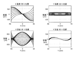
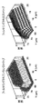
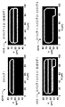
図1Aは、ワークピース10内に深いトレンチ20を形成するためにビーム軸がこれに沿って移動し得る従来の一群のビーム軌跡22,24,26,28,30の平面図である。図1Bは、所望の深さのトレンチ20を得るためにビーム軸が図1Aに示されるビーム軌跡22,24,26,28,30のそれぞれに沿って方向付けられ得るパス数のグラフである。図1Cは、図1Aに示されるビーム軌跡22,24,26,28,30に沿ったトレンチの深さのグラフである。図1A〜図1Cは、所望の深さを得るためにワークピース10の上面でどのようにしてトレンチ20を広げる必要があり、これがスループットに悪影響を与える加工時間を増やし得るかを示している。
FIG. 1A is a plan view of a conventional group of
本概要は、詳細な説明においてさらに述べられる概念を厳選したものを簡略化した形態で紹介するために提供されるものである。本概要は、特許請求の範囲に記載された主題の重要な又は必須の創作的な概念を特定すること意図しているものでも、あるいは、特許請求の範囲に記載された主題の範囲を限定することを意図しているものでもない。 This overview is provided to introduce in a simplified form a carefully selected concept further described in the detailed description. This summary is intended to identify important or essential creative concepts of the subject matter described in the claims, or limits the scope of the subject matter described in the claims. Nor is it intended to be.
一実施形態においては、レーザビームをディザリングする方法は、ビーム軌跡に沿った加工速度が変化することとは関係なく、ワークピース内に1以上の所望のトレンチ幅を有するトレンチを形成する。上記方法は、ビーム軌跡に沿った、上記ワークピースの表面に対するレーザビーム光路の第1の相対移動を生じさせ、複数のディザ行に沿った上記レーザビーム光路の第2の相対移動を決定する。上記第2の相対移動は、上記ビーム軌跡に対して所定の角度で上記第1の相対移動に重ね合わされる。上記第2の相対移動の決定は、上記複数のディザ行のそれぞれに対して上記所定の角度を維持するために加工速度の変化を補償することを含んでいる。上記方法は、さらに、上記レーザビーム光路の上記第2の相対移動を生じさせ、複数のレーザビームパルスを上記複数のディザ行に沿った複数のスポット位置で上記ワークピースに照射して、上記所定の角度で定義される方向にトレンチを広げる。ある実施形態においては、上記所定の角度は上記ビーム軌跡に対して垂直である。加えて、あるいは他の実施形態においては、上記複数のレーザビームパルスを照射することは一定の速度で照射することを含み、上記方法は、さらに、整数個のディザ行を加工して上記トレンチを完成させるように上記加工速度を選択的に調整する。 In one embodiment, the method of dithering a laser beam forms a trench with one or more desired trench widths in the workpiece, regardless of changes in machining speed along the beam trajectory. The method causes a first relative movement of the laser beam optical path with respect to the surface of the workpiece along the beam trajectory and determines a second relative movement of the laser beam optical path along a plurality of dither rows. The second relative movement is superimposed on the first relative movement at a predetermined angle with respect to the beam trajectory. The second relative movement determination includes compensating for changes in machining speed to maintain the predetermined angle with respect to each of the plurality of dither rows. The method further causes the second relative movement of the laser beam optical path and irradiates the workpiece with a plurality of laser beam pulses at a plurality of spot positions along the plurality of dither rows to determine the predetermined. Widen the trench in the direction defined by the angle of. In certain embodiments, the predetermined angle is perpendicular to the beam trajectory. In addition, or in other embodiments, irradiating the plurality of laser beam pulses comprises irradiating at a constant rate, the method further processing an integer number of dither rows to form the trench. The processing speed is selectively adjusted so as to be completed.
他の実施形態においては、レーザ加工システムは、ビーム軌跡に沿った、ワークピースの表面に対するレーザビーム光路の第1の相対移動を生じさせる第1の位置決めシステムと、複数のディザ行に沿った上記レーザビーム光路の第2の相対移動を決定する1以上のプロセッサとを備えている。上記第2の相対移動は、上記ビーム軌跡に対して所定の角度で上記第1の相対移動に重ね合わされる。上記第2の相対移動の決定は、上記複数のディザ行のそれぞれに対して上記所定の角度を維持するように上記ビーム軌跡に沿った加工速度の変化を補償することを含んでいる。また、上記システムは、上記レーザビーム光路の上記第2の相対移動を生じさせる第2の位置決めシステムと、複数のレーザビームパルスを上記複数のディザ行に沿った複数のスポット位置で上記ワークピースに照射して、上記所定の角度で定義される方向にトレンチを広げるレーザ源とを備えている。 In another embodiment, the laser machining system includes a first positioning system that causes a first relative movement of the laser beam optical path with respect to the surface of the workpiece along the beam trajectory, and the above along a plurality of dither rows. It includes one or more processors that determine the second relative movement of the laser beam optical path. The second relative movement is superimposed on the first relative movement at a predetermined angle with respect to the beam trajectory. The determination of the second relative movement includes compensating for changes in machining speed along the beam trajectory so as to maintain the predetermined angle with respect to each of the plurality of dither rows. In addition, the system includes a second positioning system that causes the second relative movement of the laser beam optical path, and a plurality of laser beam pulses on the workpiece at a plurality of spot positions along the plurality of dither rows. It is equipped with a laser source that irradiates and widens the trench in the direction defined by the predetermined angle.
他の実施形態においては、レーザビームをディザリングする方法は、ワークピースにトレンチを生成する。上記方法は、上記トレンチの長さを定義するビーム軌跡に沿った、上記ワークピースの表面に対するレーザビーム光路の第1の相対移動を生じさせ、複数のディザ行に沿った上記レーザビーム光路の上記第2の相対移動を生じさせる。上記第2の相対移動は、上記トレンチを広げるために上記第1の相対移動に重ね合わされる。上記トレンチの幅は可変である。上記方法は、さらに、上記複数のディザ行のそれぞれに含まれるディザ点の数を選択する。当該選択により各ディザ行を加工する時間が短縮され、各ディザ行における上記ディザ点の数はそれぞれのディザ行に対応する上記トレンチの上記幅に基づいたものである。上記方法は、さらに、複数のレーザビームパルスを上記複数のディザ行のそれぞれにおける上記ディザ点に対応する複数のスポット位置で上記ワークピースに照射する。 In another embodiment, the method of dithering a laser beam creates a trench in the workpiece. The method causes a first relative movement of the laser beam optical path with respect to the surface of the workpiece along a beam trajectory that defines the length of the trench, thereby causing the laser beam optical path along a plurality of dither rows. It causes a second relative movement. The second relative movement is superimposed on the first relative movement to widen the trench. The width of the trench is variable. The method further selects the number of dither points included in each of the plurality of dither lines. The selection reduces the time it takes to process each dither row, and the number of dither points in each dither row is based on the width of the trench corresponding to each dither row. The method further irradiates the workpiece with a plurality of laser beam pulses at a plurality of spot positions corresponding to the dither points in each of the dither rows.
他の実施形態においては、ワークピース上の2次元のスカイブ領域をレーザ加工する方法は、レーザダイレクトアブレーションシステムを用いる。上記方法は、上記スカイブ領域内でレーザスポット位置のグリッドを生成する。上記グリッド内の上記レーザスポット位置間の間隔は、少なくとも部分的にレーザスポットサイズ及び隣接するレーザスポットの所望の重なりに基づいている。上記方法は、さらに、上記グリッドをビーム軌跡に沿ったレーザビーム光路のそれぞれのパスに対応する複数のストリップに分割する。各ストリップは、上記ビーム軌跡に対してディザ方向に沿った複数のディザ行を含む。上記方法は、さらに、上記複数のストリップにわたって連続的に上記ビーム軌跡に沿った上記レーザビーム光路の第1の相対移動を生じさせ、各ディザ行に対して上記ディザ方向に沿った上記レーザビーム光路の第2の相対移動を生じさせ、上記スカイブ領域内の上記レーザスポット位置への上記レーザビーム光路に沿って複数のレーザビームパルスを上記ワークピースに照射する。ある実施形態においては、上記方法は、上記ディザ行のそれぞれに対してデータをフィルタリングして、上記グリッドの隣接するストリップの両側に沿ってレーザスポット強度プロファイルに傾斜を付け、深さの変化が上記スカイブ領域内で制御されるように上記レーザビームの上記パス間に重なりを形成する。上記複数のレーザビームパルスのそれぞれに対する上記レーザスポット強度は、上記フィルタリングされたデータに基づいて選択される。加えて、あるいは他の実施形態においては、上記方法は、上記レーザビーム光路が上記グリッドの第1のストリップから上記グリッドの第2のストリップに移動するときに、上記ディザ方向を反転させる。上記ディザ方向は、上記ビーム軌跡の方向に基づいていてもよい。 In another embodiment, the method of laser machining a two-dimensional skive region on a workpiece uses a laser direct ablation system. The method produces a grid of laser spot positions within the skive region. The spacing between the laser spot positions in the grid is at least partially based on the laser spot size and the desired overlap of adjacent laser spots. The method further divides the grid into a plurality of strips corresponding to each path of the laser beam optical path along the beam trajectory. Each strip contains a plurality of dither rows along the dither direction with respect to the beam trajectory. The method further causes a first relative movement of the laser beam optical path along the beam trajectory continuously over the plurality of strips, and for each dither row, the laser beam optical path along the dither direction. The second relative movement of the above is generated, and a plurality of laser beam pulses are applied to the workpiece along the laser beam optical path to the laser spot position in the skive region. In certain embodiments, the method filters data for each of the dither rows to slope the laser spot intensity profile along both sides of adjacent strips of the grid, with changes in depth. Overlapping is formed between the paths of the laser beam so that it is controlled within the skive region. The laser spot intensity for each of the plurality of laser beam pulses is selected based on the filtered data. In addition, or in other embodiments, the method reverses the dither direction as the laser beam optical path moves from the first strip of the grid to the second strip of the grid. The dither direction may be based on the direction of the beam trajectory.
代替的な、付加的な、あるいは累積的な実施形態では、レーザビームをディザリングしてワークピース内にビーム軌跡に沿ってフィーチャを形成する方法は、レーザ源から、上記ワークピースの表面に対してレーザビーム軸を形成するレーザビーム経路に沿った複数のレーザビームパルスを生成し、第1の位置決めシステムを用いて、上記ワークピースの上記表面に対して上記ビーム軌跡に沿った上記レーザビーム軸の第1の相対移動を生じさせ、上記第1の位置決めシステムは、第1のビーム偏向範囲を提供し、第2の位置決めシステムを用いて、上記第1の相対移動に重ねられる上記レーザビーム軸の第2の相対移動を生じさせ、上記第2の位置決めシステムは、上記第1のビーム偏向範囲よりも小さい第2のビーム偏向範囲を提供し、上記第2の相対移動は、上記ビーム軌跡を横切る方向成分を含み、上記ビーム軌跡に沿ったレーザパス中に、上記第2の位置決めシステムの上記偏向範囲内でレーザビームパルスを複数の選択的スポット位置のそれぞれで上記ワークピースに照射し、それぞれの選択的スポット位置は、隣り合う選択的スポット位置に空間的により近くて、空間的に隣り合わない選択的スポット位置から空間的により遠くにあり、上記ワークピースに照射される時間的に連続するレーザビームパルスは、上記第2の位置決めシステムの上記偏向範囲内で隣り合わない選択的スポット位置に照射される。 In an alternative, additional, or cumulative embodiment, the method of dithering the laser beam to form features in the workpiece along the beam trajectory is from the laser source to the surface of the workpiece. Generates a plurality of laser beam pulses along the laser beam path forming the laser beam axis, and uses the first positioning system to generate the laser beam axis along the beam trajectory with respect to the surface of the workpiece. The first relative movement of the laser beam axis provides a first beam deflection range and is superimposed on the first relative movement using the second positioning system. The second relative movement provides a second beam deflection range that is smaller than the first beam deflection range, and the second relative movement follows the beam trajectory. The workpieces are irradiated with laser beam pulses at each of the plurality of selective spot positions within the deflection range of the second positioning system during the laser path along the beam trajectory, including the crossing directional component. The selective spot position is spatially closer to the adjacent selective spot position and spatially farther from the spatially non-adjacent selective spot position, and the time-continuous laser irradiating the workpiece. The beam pulse is applied to non-adjacent selective spot positions within the deflection range of the second positioning system.
代替的な、付加的な、あるいは累積的な実施形態では、レーザビームをディザリングしてワークピース内にビーム軌跡に沿ってフィーチャを形成する方法は、レーザ源から、上記ワークピースの表面に対してレーザビーム軸を形成するレーザビーム経路に沿った複数のレーザビームパルスを生成し、第1の位置決めシステムを用いて、上記ワークピースの上記表面に対して上記ビーム軌跡に沿った上記レーザビーム軸の第1の相対移動を生じさせ、上記第1の位置決めシステムは、第1のビーム偏向範囲を提供し、第2の位置決めシステムを用いて、上記第1の相対移動に重ねられる上記レーザビーム軸の第2の相対移動を生じさせ、上記第2の位置決めシステムは、上記第1のビーム偏向範囲よりも小さい第2のビーム偏向範囲を提供し、上記第2の相対移動は、上記ビーム軌跡を横切る方向成分を含み、上記ビーム軌跡に沿ったレーザパス中に、上記第2の位置決めシステムの上記偏向範囲内でレーザビームパルスを複数の選択的スポット位置のそれぞれで上記ワークピースに照射し、上記複数のレーザビームパルスのうち選択されたレーザビームパルスは、上記ワークピースに当たらないようにブロックされ、上記レーザパス中に上記ワークピースに照射された上記レーザビームパルスは、上記第2の位置決めシステムの上記偏向範囲内で3次元パターニングを提供し、上記3次元パターニングは、上記ビーム軌跡を横切り、上記ワークピースの上記表面に対して深さ方向に2以上の深さとなるパターニングを含む。 In an alternative, additional, or cumulative embodiment, the method of dithering the laser beam to form features in the workpiece along the beam trajectory is from the laser source to the surface of the workpiece. Generate a plurality of laser beam pulses along the laser beam path forming the laser beam axis, and use the first positioning system to generate the laser beam axis along the beam trajectory with respect to the surface of the workpiece. The first relative movement of the laser beam axis provides a first beam deflection range and is superimposed on the first relative movement using the second positioning system. The second relative movement provides a second beam deflection range that is smaller than the first beam deflection range, and the second relative movement follows the beam trajectory. The workpiece is irradiated with a laser beam pulse at each of the plurality of selective spot positions within the deflection range of the second positioning system during the laser path along the beam trajectory, including the crossing directional component. The laser beam pulse selected from the laser beam pulses of the above is blocked so as not to hit the workpiece, and the laser beam pulse irradiated to the workpiece during the laser path is the above of the second positioning system. Providing three-dimensional patterning within the deflection range, the three-dimensional patterning includes patterning that traverses the beam trajectory and has a depth of two or more in the depth direction with respect to the surface of the workpiece.
代替的な、付加的な、あるいは累積的な実施形態では、レーザビームをディザリングしてワークピース内にビーム軌跡に沿ってフィーチャを形成する方法は、レーザ源から、上記ワークピースの表面に対してレーザビーム軸を形成するレーザビーム経路に沿った複数のレーザビームパルスを生成し、第1の位置決めシステムを用いて、上記ワークピースの上記表面に対して上記ビーム軌跡に沿った上記レーザビーム軸の第1の連続的な相対移動を生じさせ、上記第1の位置決めシステムは、第1のビーム偏向範囲を提供し、第2の位置決めシステムを用いて、上記第1の連続的な相対移動に重ねられる上記レーザビーム軸の第2の相対移動を生じさせ、上記第2の位置決めシステムは、上記第1のビーム偏向範囲よりも小さい第2のビーム偏向範囲を提供し、上記第2の相対移動は、上記ビーム軌跡を横切る非ゼロ方向成分を含み、上記ビーム軌跡に沿った主レーザパス中に、上記第2の位置決めシステムの上記偏向範囲内でレーザビームパルスを複数の選択的スポット位置のそれぞれで上記ワークピースに照射し、上記レーザビーム軸が上記第2のビーム偏向範囲内にあるときに、上記ビーム軌跡に沿った上記主レーザパス中に、上記レーザビームパルスの上記総数の80%を超える数のレーザビームパルスが上記ワークピースに照射される。 In an alternative, additional, or cumulative embodiment, the method of dithering the laser beam to form features in the workpiece along the beam trajectory is from the laser source to the surface of the workpiece. Generate a plurality of laser beam pulses along the laser beam path forming the laser beam axis, and use the first positioning system to generate the laser beam axis along the beam trajectory with respect to the surface of the workpiece. The first continuous relative movement of the above is caused, the first positioning system provides a first beam deflection range, and the second positioning system is used to make the first continuous relative movement of the above. The second relative movement of the superposed laser beam axes is caused and the second positioning system provides a second beam deflection range smaller than the first beam deflection range and the second relative movement. Contains a non-zero direction component across the beam trajectory and causes a laser beam pulse at each of the plurality of selective spot positions within the deflection range of the second positioning system during the main laser path along the beam trajectory. A number exceeding 80% of the total number of laser beam pulses in the main laser path along the beam trajectory when the workpiece is irradiated and the laser beam axis is within the second beam deflection range. The laser beam pulse of the above is applied to the workpiece.
代替的な、付加的な、あるいは累積的な実施形態では、レーザビームをディザリングしてワークピース内にビーム軌跡に沿ってフィーチャを形成する方法は、レーザ源から、上記ワークピースの表面に対してレーザビーム軸を形成するレーザビーム経路に沿った複数のレーザビームパルスを生成し、第1の位置決めシステムを用いて、上記ワークピースの上記表面に対して上記ビーム軌跡に沿った上記レーザビーム軸の第1の相対移動を生じさせ、上記第1の位置決めシステムは、第1のビーム偏向範囲を提供し、第2の位置決めシステムを用いて、上記第1の相対移動に重ねられる上記レーザビーム軸の第2の相対移動を生じさせ、上記第2の位置決めシステムは、上記第1のビーム偏向範囲よりも小さい第2のビーム偏向範囲を提供し、上記第2の相対移動は、上記ビーム軌跡を横切る方向成分を含み、上記ビーム軌跡に沿った主レーザパス中に、上記第2の位置決めシステムの上記偏向範囲内で複数のレーザビームパルスを1以上の選択的スポット位置のそれぞれで上記ワークピースに照射する。代替的な、付加的な、あるいは累積的な実施形態では、レーザビームをディザリングしてワークピース内にビーム軌跡に沿ってフィーチャを形成する方法は、レーザ源から、上記ワークピースの表面に対してレーザビーム軸を形成するレーザビーム経路に沿った複数のレーザビームパルスを生成し、第1の位置決めシステムを用いて、上記ワークピースの上記表面に対して上記ビーム軌跡に沿った上記レーザビーム軸の第1の連続的な相対移動を生じさせ、上記第1の位置決めシステムは、第1のビーム偏向範囲を提供し、第2の位置決めシステムを用いて、上記第1の連続的な相対移動に重ねられる上記レーザビーム軸の第2の相対移動を生じさせ、上記第2の位置決めシステムは、上記第1のビーム偏向範囲よりも小さい第2のビーム偏向範囲を提供し、上記第2の相対移動は、上記ビーム軌跡を横切る非ゼロ方向成分を含み、上記レーザビームパルスのエネルギーを選択的に制御し、上記ビーム軌跡に沿った主レーザパス中に、上記第2の位置決めシステムの上記偏向範囲内でレーザビームパルスを複数の選択的スポット位置のそれぞれで上記ワークピースに照射し、上記ワークピースに照射された上記レーザビームパルスのうちの2つ以上は、上記第2の相対移動により向けられた異なるスポット位置で異なるエネルギーを有する。 In an alternative, additional, or cumulative embodiment, the method of dithering the laser beam to form features in the workpiece along the beam trajectory is from the laser source to the surface of the workpiece. Generate a plurality of laser beam pulses along the laser beam path forming the laser beam axis, and use the first positioning system to generate the laser beam axis along the beam trajectory with respect to the surface of the workpiece. The first relative movement of the laser beam axis provides a first beam deflection range and is superimposed on the first relative movement using the second positioning system. The second relative movement provides a second beam deflection range that is smaller than the first beam deflection range, and the second relative movement follows the beam trajectory. A plurality of laser beam pulses are applied to the workpiece at each of one or more selective spot positions within the deflection range of the second positioning system during the main laser path along the beam trajectory, including the crossing directional component. To do. In an alternative, additional, or cumulative embodiment, the method of dithering the laser beam to form features in the workpiece along the beam trajectory is from the laser source to the surface of the workpiece. Generate a plurality of laser beam pulses along the laser beam path forming the laser beam axis, and use the first positioning system to generate the laser beam axis along the beam trajectory with respect to the surface of the workpiece. The first continuous relative movement of the above is caused, the first positioning system provides a first beam deflection range, and the second positioning system is used to make the first continuous relative movement of the above. The second relative movement of the superposed laser beam axes is caused and the second positioning system provides a second beam deflection range smaller than the first beam deflection range and the second relative movement. Contains a non-zero direction component across the beam trajectory, selectively controls the energy of the laser beam pulse, and within the deflection range of the second positioning system during the main laser path along the beam trajectory. A laser beam pulse is applied to the workpiece at each of the plurality of selective spot positions, and two or more of the laser beam pulses irradiated to the workpiece are differently directed by the second relative movement. It has different energies at the spot location.
代替的な、付加的な、あるいは累積的な実施形態では、レーザビームをディザリングしてワークピース内にビーム軌跡に沿ってフィーチャを形成する方法は、レーザ源から、上記ワークピースの表面に対してレーザビーム軸を形成するレーザビーム経路に沿った複数のレーザビームパルスを生成し、第1の位置決めシステムを用いて、上記ワークピースの上記表面に対して上記ビーム軌跡に沿った上記レーザビーム軸の第1の連続的な相対移動を生じさせ、上記第1の位置決めシステムは、第1のビーム偏向範囲を提供し、第2の位置決めシステムを用いて、上記第1の連続的な相対移動に重ねられる上記レーザビーム軸の第2の相対移動を生じさせ、上記第2の位置決めシステムは、上記第1のビーム偏向範囲よりも小さい第2のビーム偏向範囲を提供し、上記第2の相対移動は、上記ビーム軌跡を横切る非ゼロ方向成分を含み、上記ビーム軌跡に沿った主レーザパス中に、上記第2の位置決めシステムの上記偏向範囲内でレーザビームパルスを複数の選択的スポット位置のそれぞれで上記ワークピースに照射し、上記レーザビーム軸が上記第2のビーム偏向範囲内にあるときに、上記レーザ源は、上記ビーム軌跡に沿った上記主レーザパス中に、ある総数のレーザビームパルスを生成し、上記レーザビームパルスの上記総数は、上記ビーム軌跡から5ミクロンの距離の範囲内で上記ビーム軌跡に沿って上記レーザビームパルスの上記総数で上記ワークピースに当たるための加工ウィンドウの動作フルエンスを超える合計フルエンスを提供する。 In an alternative, additional, or cumulative embodiment, the method of dithering the laser beam to form features in the workpiece along the beam trajectory is from the laser source to the surface of the workpiece. Generate a plurality of laser beam pulses along the laser beam path forming the laser beam axis, and use the first positioning system to generate the laser beam axis along the beam trajectory with respect to the surface of the workpiece. The first continuous relative movement of the above is caused, the first positioning system provides a first beam deflection range, and the second positioning system is used to make the first continuous relative movement of the above. The second relative movement of the superposed laser beam axes is caused and the second positioning system provides a second beam deflection range smaller than the first beam deflection range and the second relative movement. Contains a non-zero direction component across the beam trajectory and causes a laser beam pulse at each of the plurality of selective spot positions within the deflection range of the second positioning system during the main laser path along the beam trajectory. When the workpiece is irradiated and the laser beam axis is within the second beam deflection range, the laser source produces a total number of laser beam pulses in the main laser path along the beam trajectory. However, the total number of the laser beam pulses exceeds the operating fluence of the machining window for hitting the workpiece with the total number of the laser beam pulses along the beam trajectory within a distance of 5 microns from the beam trajectory. Provides total fluence.
代替的な、付加的な、あるいは累積的な実施形態では、レーザビームをディザリングしてワークピース内にビーム軌跡に沿ってフィーチャを形成する方法は、レーザ源から、上記ワークピースの表面に対してレーザビーム軸を形成するレーザビーム経路に沿った複数のレーザビームパルスを生成し、第1の位置決めシステムを用いて、上記ワークピースの上記表面に対して上記ビーム軌跡に沿った上記レーザビーム軸の第1の連続的な相対移動を生じさせ、上記第1の位置決めシステムは、第1のビーム偏向範囲を提供し、第2の位置決めシステムを用いて、上記第1の連続的な相対移動に重ねられる上記レーザビーム軸の第2の相対移動を生じさせ、上記第2の位置決めシステムは、上記第1のビーム偏向範囲よりも小さい第2のビーム偏向範囲を提供し、上記第2の相対移動は、上記ビーム軌跡を横切る非ゼロ方向成分を含み、上記ビーム軌跡に沿った主レーザパス中に、上記第2の位置決めシステムの上記偏向範囲内で動作レーザビームパルスを複数の選択的スポット位置のそれぞれで上記ワークピースに照射し、上記レーザビーム軸が上記第2のビーム偏向範囲内にあるときに、上記レーザ源は、上記ビーム軌跡に沿った上記主レーザパス中に、ある総数のレーザビームパルスを生成し、上記レーザビームパルスの上記総数は、上記ビーム軌跡から5ミクロンの距離の範囲内で上記ビーム軌跡に沿って上記ワークピースに当たるために動作しているレーザビームパルスの所望の数を10%よりも多く超える。 In an alternative, additional, or cumulative embodiment, the method of dithering the laser beam to form features in the workpiece along the beam trajectory is from the laser source to the surface of the workpiece. Generate a plurality of laser beam pulses along the laser beam path forming the laser beam axis, and use the first positioning system to generate the laser beam axis along the beam trajectory with respect to the surface of the workpiece. The first continuous relative movement of the above is caused, the first positioning system provides a first beam deflection range, and the second positioning system is used to make the first continuous relative movement of the above. The second relative movement of the superposed laser beam axes is caused and the second positioning system provides a second beam deflection range smaller than the first beam deflection range and the second relative movement. Contains a non-zero direction component across the beam trajectory and operates within the deflection range of the second positioning system during the main laser path along the beam trajectory, each of a plurality of selective spot positions. When the workpiece is irradiated with and the laser beam axis is within the second beam deflection range, the laser source produces a total number of laser beam pulses in the main laser path along the beam trajectory. The total number of laser beam pulses generated is 10% of the desired number of laser beam pulses operating to hit the workpiece along the beam trajectory within a distance of 5 microns from the beam trajectory. More than
代替的な、付加的な、あるいは累積的な実施形態では、レーザビームをディザリングしてワークピース内にビーム軌跡に沿ってフィーチャを形成する方法は、レーザ源から、上記ワークピースの表面に対してレーザビーム軸を形成するレーザビーム経路に沿った複数のレーザビームパルスを生成し、第1の位置決めシステムを用いて、上記ワークピースの上記表面に対して上記ビーム軌跡に沿った上記レーザビーム軸の第1の連続的な相対移動を生じさせ、上記第1の位置決めシステムは、第1のビーム偏向範囲を提供し、第2の位置決めシステムを用いて、上記第1の連続的な相対移動に重ねられる上記レーザビーム軸の第2の相対移動を生じさせ、上記第2の位置決めシステムは、上記第1のビーム偏向範囲よりも小さい第2のビーム偏向範囲を提供し、上記第2の相対移動は、上記ビーム軌跡を横切る非ゼロ方向成分を含み、上記ビーム軌跡に沿った主レーザパス中に、上記第2の位置決めシステムの上記偏向範囲内で動作レーザビームパルスを複数の選択的スポット位置のそれぞれであるスポットサイズで上記ワークピースに照射し、上記レーザビーム軸が上記第2のビーム偏向範囲内にあるときに、上記レーザ源は、上記ビーム軌跡に沿った上記主レーザパス中に、ある総数のレーザビームパルスを生成し、上記レーザビームパルスの上記総数は、上記ビーム軌跡からあるスポットサイズの距離の範囲内で上記ビーム軌跡に沿って上記ワークピースに当たるために動作しているレーザビームパルスの所望の数を10%よりも多く超える。 In an alternative, additional, or cumulative embodiment, the method of dithering the laser beam to form features in the workpiece along the beam trajectory is from the laser source to the surface of the workpiece. Generate a plurality of laser beam pulses along the laser beam path forming the laser beam axis, and use the first positioning system to generate the laser beam axis along the beam trajectory with respect to the surface of the workpiece. The first continuous relative movement of the above is caused, the first positioning system provides a first beam deflection range, and the second positioning system is used to make the first continuous relative movement of the above. The second relative movement of the superposed laser beam axes is caused and the second positioning system provides a second beam deflection range smaller than the first beam deflection range and the second relative movement. Contains a non-zero direction component across the beam trajectory and operates within the deflection range of the second positioning system during the main laser path along the beam trajectory, each of a plurality of selective spot positions. When the workpiece is irradiated with a spot size of, and the laser beam axis is within the second beam deflection range, the laser source has a total number of laser sources in the main laser path along the beam trajectory. The desired total number of laser beam pulses that generate a laser beam pulse and are operating to hit the workpiece along the beam trajectory within a spot size distance from the beam trajectory. More than 10%.
代替的な、付加的な、あるいは累積的な実施形態では、それぞれの選択的スポット位置は、隣り合う選択的スポット位置に対して空間的に近接し、空間的に隣り合わない選択的スポット位置から空間的に離れており、上記ワークピースに照射される時間的に連続するレーザビームパルスは、上記第2の位置決めシステムの上記偏向範囲内で隣り合わない選択的スポット位置に照射される。 In an alternative, additional, or cumulative embodiment, each selective spot position is spatially close to adjacent selective spot positions and from spatially non-adjacent selective spot positions. Spatically separated, temporally continuous laser beam pulses applied to the workpiece are applied to non-adjacent selective spot positions within the deflection range of the second positioning system.
代替的な、付加的な、あるいは累積的な実施形態では、2次レーザパス中に上記ワークピースに照射された上記レーザビームパルスは、上記第2の位置決めシステムの上記偏向範囲内で3次元パターニングを提供し、上記3次元パターニングは、上記ビーム軌跡を横切り、上記ワークピースの上記表面に対してそれぞれのスポット位置で深さ方向に2以上の深さとなるパターニングを含む。 In an alternative, additional, or cumulative embodiment, the laser beam pulse applied to the workpiece during the secondary laser path causes three-dimensional patterning within the deflection range of the second positioning system. Provided, the three-dimensional patterning includes patterning that traverses the beam trajectory and has a depth of two or more in the depth direction at each spot position with respect to the surface of the workpiece.
代替的な、付加的な、あるいは累積的な実施形態では、上記第2の相対移動は、非ゼロX方向成分及び非ゼロY方向成分の双方を含む。 In an alternative, additional, or cumulative embodiment, the second relative movement includes both a non-zero X-direction component and a non-zero Y-direction component.
代替的な、付加的な、あるいは累積的な実施形態では、上記第2のビーム偏向範囲は、横方向に0.01mmから4.0mmの間で延びる。 In an alternative, additional, or cumulative embodiment, the second beam deflection range extends laterally between 0.01 mm and 4.0 mm.
代替的な、付加的な、あるいは累積的な実施形態では、上記第2のビーム偏向範囲は、横方向に0.01mmから2.5mmの間で延びる。 In an alternative, additional, or cumulative embodiment, the second beam deflection range extends laterally between 0.01 mm and 2.5 mm.
代替的な、付加的な、あるいは累積的な実施形態では、上記エネルギーは、上記第2の位置決めシステムの上記偏向範囲内で上記選択的スポット位置のうち時間的に連続的に向けられた位置で異なるように選択的に制御される。 In an alternative, additional, or cumulative embodiment, the energy is directed in time-continuously of the selective spot positions within the deflection range of the second positioning system. It is selectively controlled to be different.
代替的な、付加的な、あるいは累積的な実施形態では、上記エネルギーは、上記第2の位置決めシステムの上記偏向範囲内で上記選択的スポット位置のうち時間的に連続的に向けられたグループで異なるように選択的に制御される。 In an alternative, additional, or cumulative embodiment, the energy is directed in a temporally continuous group of the selective spot positions within the deflection range of the second positioning system. It is selectively controlled to be different.
代替的な、付加的な、あるいは累積的な実施形態では、上記レーザビームパルスのスポットサイズは、上記第2の位置決めシステムの上記偏向範囲内で上記選択的スポット位置のうち時間的に連続的に向けられた位置で異なるように選択的に制御される。 In an alternative, additional, or cumulative embodiment, the spot size of the laser beam pulse is temporally continuous of the selective spot positions within the deflection range of the second positioning system. It is selectively controlled to be different depending on the directed position.
代替的な、付加的な、あるいは累積的な実施形態では、上記レーザビームパルスのスポットサイズは、上記第2の位置決めシステムの上記偏向範囲内で上記選択的スポット位置のうち時間的に連続的に向けられたグループで異なるように選択的に制御される。 In an alternative, additional, or cumulative embodiment, the spot size of the laser beam pulse is temporally continuous of the selective spot positions within the deflection range of the second positioning system. It is selectively controlled differently in the directed group.
代替的な、付加的な、あるいは累積的な実施形態では、上記レーザビームの焦点は、上記第2の位置決めシステムの上記偏向範囲内で上記選択的スポット位置のうち時間的に連続的に向けられた位置で異なるように選択的に制御される。 In an alternative, additional, or cumulative embodiment, the laser beam is focused in time and continuously of the selective spot positions within the deflection range of the second positioning system. It is selectively controlled so that it differs depending on the position.
代替的な、付加的な、あるいは累積的な実施形態では、上記レーザビームの焦点は、上記第2の位置決めシステムの上記偏向範囲内で上記選択的スポット位置のうち時間的に連続的に向けられたグループで異なるように選択的に制御される。 In an alternative, additional, or cumulative embodiment, the laser beam is focused in time and continuously of the selective spot positions within the deflection range of the second positioning system. It is selectively controlled to be different in each group.
代替的な、付加的な、あるいは累積的な実施形態では、上記第2の位置決めシステムの上記偏向範囲内で上記選択的スポット位置のうち時間的に連続的に向けられた位置は、空間的に近接していない。 In an alternative, additional, or cumulative embodiment, the temporally and continuously oriented positions of the selective spot positions within the deflection range of the second positioning system are spatially oriented. Not in close proximity.
代替的な、付加的な、あるいは累積的な実施形態では、上記第2の位置決めシステムの上記偏向範囲内で上記選択的スポット位置のうち時間的に連続的に向けられた位置は、空間的に近接している。 In an alternative, additional, or cumulative embodiment, the temporally and continuously oriented positions of the selective spot positions within the deflection range of the second positioning system are spatially oriented. Close to each other.
代替的な、付加的な、あるいは累積的な実施形態では、上記第2の相対移動は、時間的に分離した反対方向成分を含む。 In an alternative, additional, or cumulative embodiment, the second relative movement comprises a temporally separated opposite direction component.
代替的な、付加的な、あるいは累積的な実施形態では、上記時間的に分離した反対方向成分は、上記ビーム軌跡を横切る方向である。 In an alternative, additional, or cumulative embodiment, the temporally separated opposite directional components are in the direction across the beam trajectory.
代替的な、付加的な、あるいは累積的な実施形態では、上記時間的に分離した反対方向成分のうちの1つは、上記ビーム軌跡と反対の方向である。 In an alternative, additional, or cumulative embodiment, one of the temporally separated opposite direction components is in the direction opposite to the beam trajectory.
代替的な、付加的な、あるいは累積的な実施形態では、上記方向成分は、上記ビーム軌跡に対する上記第2の相対移動の成分ベクトルである。 In an alternative, additional, or cumulative embodiment, the directional component is the component vector of the second relative movement with respect to the beam trajectory.
代替的な、付加的な、あるいは累積的な実施形態では、上記ワークピースに照射される上記レーザビームパルスのうち2以上のレーザビームパルスは、上記第2の相対移動の単一の2次パス中に異なるスポット位置で異なるエネルギーを有する。 In an alternative, additional, or cumulative embodiment, two or more of the laser beam pulses irradiated on the workpiece are single secondary paths of the second relative movement. It has different energies at different spot positions inside.
代替的な、付加的な、あるいは累積的な実施形態では、上記第2の相対移動は非楕円移動である。 In an alternative, additional, or cumulative embodiment, the second relative movement is a non-elliptical movement.
代替的な、付加的な、あるいは累積的な実施形態では、上記第2の相対移動は非楕円移動である。 In an alternative, additional, or cumulative embodiment, the second relative movement is a non-elliptical movement.
代替的な、付加的な、あるいは累積的な実施形態では、上記ビーム軌跡に沿った上記主レーザパスは、いずれのスポット位置についても一度上記ビーム軸をスイープする。 In an alternative, additional, or cumulative embodiment, the main laser path along the beam trajectory sweeps the beam axis once at any spot location.
代替的な、付加的な、あるいは累積的な実施形態では、上記ビーム軌跡に沿った上記2次レーザパスは、いずれのスポット位置についても一度上記ビーム軸をスイープする。 In an alternative, additional, or cumulative embodiment, the secondary laser path along the beam trajectory sweeps the beam axis once at any spot location.
代替的な、付加的な、あるいは累積的な実施形態では、上記2次レーザパスは、いずれのスポット位置についても一度上記ビーム軸をスイープする。 In an alternative, additional, or cumulative embodiment, the secondary laser path sweeps the beam axis once for any spot position.
代替的な、付加的な、あるいは累積的な実施形態では、上記第2の相対移動は、上記ビーム軌跡に沿った上記主レーザパス中の上記第2のビーム偏向範囲内における上記ビーム軸の複数のレーザパスを含む。 In an alternative, additional, or cumulative embodiment, the second relative movement is a plurality of the beam axes within the second beam deflection range in the main laser path along the beam trajectory. Includes laser path.
代替的な、付加的な、あるいは累積的な実施形態では、上記ワークピースに照射される時間的に連続するレーザビームパルスは、上記第2のビーム偏向範囲の25%以上の相互間距離にある選択的スポット位置に照射される。 In an alternative, additional, or cumulative embodiment, the temporally continuous laser beam pulses applied to the workpiece are at a distance of 25% or more of the second beam deflection range. The selective spot position is illuminated.
代替的な、付加的な、あるいは累積的な実施形態では、上記ワークピースに照射される時間的に連続するレーザビームパルスは、上記第2のビーム偏向範囲の50%以上の相互間距離にある選択的スポット位置に照射される。 In an alternative, additional, or cumulative embodiment, the temporally continuous laser beam pulses applied to the workpiece are at a distance of 50% or more of the second beam deflection range. The selective spot position is illuminated.
代替的な、付加的な、あるいは累積的な実施形態では、上記ワークピースに照射される時間的に連続するレーザビームパルスは、上記第2のビーム偏向範囲の75%以上の相互間距離にある選択的スポット位置に照射される。 In an alternative, additional, or cumulative embodiment, the temporally continuous laser beam pulses applied to the workpiece are at a distance of 75% or more of the second beam deflection range. The selective spot position is illuminated.
代替的な、付加的な、あるいは累積的な実施形態では、上記ワークピースに照射される時間的に連続するレーザビームパルスは、上記第2のビーム偏向範囲の90%以上の相互間距離にある選択的スポット位置に照射される。 In an alternative, additional, or cumulative embodiment, the temporally continuous laser beam pulses applied to the workpiece are at a distance of 90% or more of the second beam deflection range. The selective spot position is illuminated.
代替的な、付加的な、あるいは累積的な実施形態では、上記ワークピースに照射される上記時間的に連続するレーザビームパルスの上記選択的スポット位置間の距離は、上記第2のビーム偏向範囲、上記第1の位置決めシステムが上記ビーム軌跡に沿って上記ビーム軸を移動させる第1の速度、及び上記第2の位置決めシステムが上記ビーム軸を移動させる第2の速度の関数である。 In an alternative, additional, or cumulative embodiment, the distance between the selective spot positions of the temporally continuous laser beam pulses applied to the workpiece is the second beam deflection range. It is a function of the first speed at which the first positioning system moves the beam axis along the beam trajectory, and the second speed at which the second positioning system moves the beam axis.
代替的な、付加的な、あるいは累積的な実施形態では、隣り合う上記選択的スポット位置が重なり合う。 In an alternative, additional, or cumulative embodiment, adjacent selective spot locations overlap.
代替的な、付加的な、あるいは累積的な実施形態では、上記第1のビーム位置決めシステムは、上記ビーム軌跡に沿った上記第1のビーム位置決めシステムの最大速度の25%以上で上記ビーム軸を移動させる。 In an alternative, additional, or cumulative embodiment, the first beam positioning system aligns the beam axis at 25% or more of the maximum velocity of the first beam positioning system along the beam trajectory. Move.
代替的な、付加的な、あるいは累積的な実施形態では、上記第1のビーム位置決めシステムは、上記ビーム軌跡に沿った上記第1のビーム位置決めシステムの最大速度の50%以上で上記ビーム軸を移動させる。 In an alternative, additional, or cumulative embodiment, the first beam positioning system aligns the beam axis at 50% or more of the maximum velocity of the first beam positioning system along the beam trajectory. Move.
代替的な、付加的な、あるいは累積的な実施形態では、上記第1のビーム位置決めシステムは、上記ビーム軌跡に沿った上記第1のビーム位置決めシステムの最大速度の75%以上で上記ビーム軸を移動させる。 In an alternative, additional, or cumulative embodiment, the first beam positioning system aligns the beam axis at 75% or more of the maximum velocity of the first beam positioning system along the beam trajectory. Move.
代替的な、付加的な、あるいは累積的な実施形態では、上記第1のビーム位置決めシステムは、上記ビーム軌跡に沿った上記第1のビーム位置決めシステムの最大速度の90%以上で上記ビーム軸を移動させる。 In an alternative, additional, or cumulative embodiment, the first beam positioning system aligns the beam axis at 90% or more of the maximum velocity of the first beam positioning system along the beam trajectory. Move.
代替的な、付加的な、あるいは累積的な実施形態では、上記フィーチャはトレンチである。 In an alternative, additional, or cumulative embodiment, the feature is a trench.
代替的な、付加的な、あるいは累積的な実施形態では、上記フィーチャは貫通切欠きである。 In an alternative, additional, or cumulative embodiment, the feature is a penetrating notch.
代替的な、付加的な、あるいは累積的な実施形態では、上記フィーチャはマークである。 In an alternative, additional, or cumulative embodiment, the feature is a mark.
代替的な、付加的な、あるいは累積的な実施形態では、上記フィーチャはサブ表面マークである。 In an alternative, additional, or cumulative embodiment, the feature is a subsurface mark.
代替的な、付加的な、あるいは累積的な実施形態では、上記フィーチャは抵抗器上のトリムである。 In an alternative, additional, or cumulative embodiment, the feature is a trim on a resistor.
代替的な、付加的な、あるいは累積的な実施形態では、上記フィーチャは非貫通ビアである。 In an alternative, additional, or cumulative embodiment, the feature is a non-penetrating via.
代替的な、付加的な、あるいは累積的な実施形態では、上記フィーチャは貫通孔ビアである。 In an alternative, additional, or cumulative embodiment, the feature is a through-hole via.
代替的な、付加的な、あるいは累積的な実施形態では、上記第2の位置決めシステムは、ゼロ慣性位置決め装置を含む。 In an alternative, additional, or cumulative embodiment, the second positioning system includes a zero inertial positioning device.
代替的な、付加的な、あるいは累積的な実施形態では、上記第2の位置決めシステムは、音響光学装置(AOD)を含む。 In an alternative, additional, or cumulative embodiment, the second positioning system includes an acoustic optics device (AOD).
代替的な、付加的な、あるいは累積的な実施形態では、上記第2の位置決めシステムは、2以上の変換器を含む。 In an alternative, additional, or cumulative embodiment, the second positioning system comprises two or more transducers.
代替的な、付加的な、あるいは累積的な実施形態では、上記第2の位置決めシステムは、2以上の偏向軸に沿って上記ビーム軸を偏向させることができる。 In an alternative, additional, or cumulative embodiment, the second positioning system can deflect the beam axis along two or more deflection axes.
代替的な、付加的な、あるいは累積的な実施形態では、上記第2の位置決めシステムは、2以上の音響光学装置(AOD)を含む。 In an alternative, additional, or cumulative embodiment, the second positioning system comprises two or more acoustic optics (AODs).
代替的な、付加的な、あるいは累積的な実施形態では、上記第2の位置決めシステムは、AODの横面上に設置された変換器を用いる。 In an alternative, additional, or cumulative embodiment, the second positioning system uses a transducer installed on the side surface of the AOD.
代替的な、付加的な、あるいは累積的な実施形態では、上記第2の位置決めシステムは、電気光学装置(EOD)を含む。 In an alternative, additional, or cumulative embodiment, the second positioning system includes an electro-optic device (EOD).
代替的な、付加的な、あるいは累積的な実施形態では、上記第2の位置決めシステムは、共振器外ビームブロッカとして機能することが可能である。 In an alternative, additional, or cumulative embodiment, the second positioning system is capable of functioning as an extra-resonator beam blocker.
代替的な、付加的な、あるいは累積的な実施形態では、上記複数のレーザビームパルスのうち選択的なレーザビームパルスをブロックするために共振器外ビームブロッカが利用される。 In an alternative, additional, or cumulative embodiment, an extrasonator beam blocker is utilized to block a selective laser beam pulse of the plurality of laser beam pulses.
代替的な、付加的な、あるいは累積的な実施形態では、上記ビーム軌跡に沿った上記レーザパス中に複数のレーザビームパルスが1つの選択的スポット位置に照射される。 In an alternative, additional, or cumulative embodiment, multiple laser beam pulses are applied to one selective spot position during the laser path along the beam trajectory.
代替的な、付加的な、あるいは累積的な実施形態では、上記ワークピースに照射される上記時間的に連続するレーザビームパルスは、上記ビーム軌跡に関して異なる軸に沿って隣り合わない選択的スポット位置に照射される。 In an alternative, additional, or cumulative embodiment, the temporally continuous laser beam pulses applied to the workpiece are non-adjacent selective spot locations along different axes with respect to the beam trajectory. Is irradiated to.
代替的な、付加的な、あるいは累積的な実施形態では、上記ワークピースに照射される上記時間的に連続するレーザビームパルスは、上記ビーム軌跡に関して単一の軸に沿って隣り合わない選択的スポット位置に照射される。 In an alternative, additional, or cumulative embodiment, the temporally continuous laser beam pulses applied to the workpiece are selective, not adjacent along a single axis with respect to the beam trajectory. The spot position is illuminated.
代替的な、付加的な、あるいは累積的な実施形態では、上記レーザパス中に上記第2の位置決めシステムのスキャンフィールド内で上記ワークピースに照射される上記時間的に連続するレーザビームパルスは、10個以上のレーザビームパルスを含む。 In an alternative, additional, or cumulative embodiment, the temporally continuous laser beam pulse irradiated on the workpiece in the scan field of the second positioning system during the laser path is 10. Includes more than one laser beam pulse.
代替的な、付加的な、あるいは累積的な実施形態では、上記レーザパス中に上記第2の位置決めシステムのスキャンフィールド内で上記ワークピースに照射される上記時間的に連続するレーザビームパルスは、100個以上のレーザビームパルスを含む。 In an alternative, additional, or cumulative embodiment, the temporally continuous laser beam pulse that irradiates the workpiece within the scan field of the second positioning system during the laser path is 100. Includes more than one laser beam pulse.
代替的な、付加的な、あるいは累積的な実施形態では、上記第2の位置決めシステムのスキャンフィールド又はビーム偏向範囲は、横方向に10個のレーザスポットより大きい長軸寸法を有する。 In an alternative, additional, or cumulative embodiment, the scan field or beam deflection range of the second positioning system has a major axis dimension greater than 10 laser spots laterally.
代替的な、付加的な、あるいは累積的な実施形態では、上記第2の位置決めシステムのスキャンフィールド又はビーム偏向範囲は、横方向に100個のレーザスポットより大きい長軸寸法を有する。 In an alternative, additional, or cumulative embodiment, the scan field or beam deflection range of the second positioning system has a major axis dimension greater than 100 laser spots laterally.
代替的な、付加的な、あるいは累積的な実施形態では、上記第2の位置決めシステムのスキャンフィールド又はビーム偏向範囲は、横方向に500個のレーザスポットより大きい長軸寸法を有する。 In an alternative, additional, or cumulative embodiment, the scan field or beam deflection range of the second positioning system has a major axis dimension greater than 500 laser spots laterally.
代替的な、付加的な、あるいは累積的な実施形態では、上記レーザパス中に上記第2の位置決めシステムのスキャンフィールド内で上記ワークピースに照射される上記時間的に連続するレーザビームパルスは、500個以上のレーザビームパルスを含む。 In an alternative, additional, or cumulative embodiment, the temporally continuous laser beam pulse that is applied to the workpiece in the scan field of the second positioning system during the laser path is 500. Includes more than one laser beam pulse.
代替的な、付加的な、あるいは累積的な実施形態では、上記ビーム軸は、上記ビーム軌跡に対して横方向にディザリングされ、それぞれのレーザパス中に上記レーザにより加工される領域を広げる。 In an alternative, additional, or cumulative embodiment, the beam axis is laterally dithered with respect to the beam trajectory, expanding the area machined by the laser in each laser path.
代替的な、付加的な、あるいは累積的な実施形態では、上記複数のレーザビームパルスは、100kHz以上のパルス繰り返し率で生成される。 In an alternative, additional, or cumulative embodiment, the plurality of laser beam pulses are generated with a pulse repetition rate of 100 kHz or greater.
代替的な、付加的な、あるいは累積的な実施形態では、上記ビーム軸と上記ワークピースとの間の上記相対運動は、上記ビーム軌跡に沿って400mm/s以上である。 In an alternative, additional, or cumulative embodiment, the relative motion between the beam axis and the workpiece is greater than or equal to 400 mm / s along the beam trajectory.
代替的な、付加的な、あるいは累積的な実施形態では、上記複数のレーザビームパルスは、100ps以下のパルス幅を有する。 In an alternative, additional, or cumulative embodiment, the plurality of laser beam pulses have a pulse width of 100 ps or less.
代替的な、付加的な、あるいは累積的な実施形態では、上記複数のレーザビームパルスは、10ps以下のパルス幅を有する。 In an alternative, additional, or cumulative embodiment, the plurality of laser beam pulses have a pulse width of 10 ps or less.
代替的な、付加的な、あるいは累積的な実施形態では、上記複数のレーザビームパルスは、1ps以下のパルス幅を有する。 In an alternative, additional, or cumulative embodiment, the plurality of laser beam pulses have a pulse width of 1 ps or less.
代替的な、付加的な、あるいは累積的な実施形態では、隣り合う選択的スポット位置間の上記バイトサイズは、4ミクロン以下である。 In an alternative, additional, or cumulative embodiment, the bite size between adjacent selective spot positions is 4 microns or less.
代替的な、付加的な、あるいは累積的な実施形態では、上記ワークピースに照射される上記時間的に連続するレーザビームパルスは、15ミクロン以下の長軸を有するスポット領域を有する。 In an alternative, additional, or cumulative embodiment, the temporally continuous laser beam pulse applied to the workpiece has a spot region with a major axis of 15 microns or less.
代替的な、付加的な、あるいは累積的な実施形態では、上記ワークピースに照射される上記時間的に連続するレーザビームパルスは、選択的レーザスポットの微細運動パターンにある。 In an alternative, additional, or cumulative embodiment, the temporally continuous laser beam pulse applied to the workpiece is in the fine motion pattern of the selective laser spot.
代替的な、付加的な、あるいは累積的な実施形態では、上記軌跡は、ビアの表面周縁部を形成する。 In an alternative, additional, or cumulative embodiment, the trajectories form the surface margins of the vias.
代替的な、付加的な、あるいは累積的な実施形態では、上記レーザビームパルスは、第1のスポット位置に照射される第1のレーザビームパルスであり、上記ワークピースに照射される上記時間的に連続するレーザビームパルスは、第2のスポット位置に照射される第2のレーザビームパルスであり、時間的に後に続くレーザビームパルスは、第3のスポット位置に照射される第3のレーザビームパルスであり、上記第3のスポット位置は、上記隣り合う選択的スポット位置である。 In an alternative, additional, or cumulative embodiment, the laser beam pulse is a first laser beam pulse that irradiates the first spot location and irradiates the workpiece over time. The laser beam pulse continuous with is the second laser beam pulse irradiated to the second spot position, and the laser beam pulse following in time is the third laser beam irradiated to the third spot position. It is a pulse, and the third spot position is the adjacent selective spot position.
代替的な、付加的な、あるいは累積的な実施形態では、上記ビーム軸を個々に選択された横方向位置に向けることができる。 In an alternative, additional, or cumulative embodiment, the beam axes can be directed to individually selected lateral positions.
代替的な、付加的な、あるいは累積的な実施形態では、上記レーザビームは、単一パス中に複数回横方向位置に向けることができる。 In an alternative, additional, or cumulative embodiment, the laser beam can be directed laterally multiple times in a single pass.
代替的な、付加的な、あるいは累積的な実施形態では、上記ワークピース上の空間的に同一のスポット領域位置、空間的に重なり合うスポット領域位置、又は空間的に隣り合うスポット領域位置に照射されるレーザパルスは、不連続である。 In an alternative, additional, or cumulative embodiment, spatially identical spot region locations, spatially overlapping spot region locations, or spatially adjacent spot region locations on the workpiece are irradiated. The laser pulses are discontinuous.
代替的な、付加的な、あるいは累積的な実施形態では、上記レーザビーム軸が上記第2のビーム偏向範囲内にあるときに、上記レーザ源は、上記ビーム軌跡に沿った上記主レーザパス中に、ある総数のレーザビームパルスを生成し、上記レーザビームパルスの上記総数は、上記レーザビーム軸の2ミクロンの範囲内で上記ビーム軌跡に沿って上記レーザビームパルスの上記総数で上記ワークピースに当たるための加工ウィンドウの動作フルエンスを超える合計フルエンスを供給する。 In an alternative, additional, or cumulative embodiment, when the laser beam axis is within the second beam deflection range, the laser source is in the main laser path along the beam trajectory. To generate a certain total number of laser beam pulses, the total number of the laser beam pulses hits the workpiece with the total number of the laser beam pulses along the beam trajectory within a range of 2 microns of the laser beam axis. Provides a total fluence that exceeds the operating fluence of the machining window.
代替的な、付加的な、あるいは累積的な実施形態では、上記レーザビームパルスの上記総数は、上記レーザビーム軸の5ミクロンの範囲内で上記ビーム軌跡に沿って上記レーザビームパルスの上記総数で上記ワークピースに当たるための加工ウィンドウの動作フルエンスを超える合計フルエンスを供給する。 In an alternative, additional, or cumulative embodiment, the total number of laser beam pulses is the total number of laser beam pulses along the beam trajectory within 5 microns of the laser beam axis. It supplies a total fluence that exceeds the operating fluence of the machining window to hit the workpiece.
代替的な、付加的な、あるいは累積的な実施形態では、上記レーザビームパルスの上記総数は、上記レーザビーム軸の10ミクロンの範囲内で上記ビーム軌跡に沿って上記レーザビームパルスの上記総数で上記ワークピースに当たるための加工ウィンドウの動作フルエンスを超える合計フルエンスを供給する。 In an alternative, additional, or cumulative embodiment, the total number of laser beam pulses is the total number of laser beam pulses along the beam trajectory within a range of 10 microns of the laser beam axis. It supplies a total fluence that exceeds the operating fluence of the machining window to hit the workpiece.
代替的な、付加的な、あるいは累積的な実施形態では、上記レーザビームパルスの上記総数は、上記レーザビーム軸の5ミクロンの範囲内で上記ビーム軌跡に沿って上記ワークピースに当たるために動作しているレーザビームパルスの所望の数を20%よりも多く超える。 In an alternative, additional, or cumulative embodiment, the total number of laser beam pulses operates to hit the workpiece along the beam trajectory within 5 microns of the laser beam axis. More than 20% more than the desired number of laser beam pulses.
代替的な、付加的な、あるいは累積的な実施形態では、上記レーザビーム軸が上記第2のビーム偏向範囲内にあるときに、上記レーザ源は、上記ビーム軌跡に沿った上記主レーザパス中に、ある総数のレーザビームパルスを生成し、上記レーザビームパルスの上記総数は、上記ビーム軌跡から5ミクロンの距離の範囲内で上記ビーム軌跡に沿って上記ワークピースに当たるために動作しているレーザビームパルスの所望の数を10%よりも多く超える。 In an alternative, additional, or cumulative embodiment, when the laser beam axis is within the second beam deflection range, the laser source is in the main laser path along the beam trajectory. , A total number of laser beam pulses are generated, and the total number of the laser beam pulses is operating to hit the workpiece along the beam trajectory within a distance of 5 microns from the beam trajectory. More than 10% more than the desired number of pulses.
代替的な、付加的な、あるいは累積的な実施形態では、上記動作しているレーザビームパルスは、上記複数の選択的スポット位置のそれぞれにおいてスポットサイズを有し、上記レーザビーム軸が上記第2のビーム偏向範囲内にあるときに、上記レーザ源は、上記ビーム軌跡に沿った上記主レーザパス中に、ある総数のレーザビームパルスを生成し、上記レーザビームパルスの上記総数は、上記ビーム軌跡からあるスポットサイズの距離の範囲内で上記ビーム軌跡に沿って上記ワークピースに当たるために動作しているレーザビームパルスの所望の数を10%よりも多く超える。 In an alternative, additional, or cumulative embodiment, the operating laser beam pulse has a spot size at each of the plurality of selective spot positions, and the laser beam axis is the second. When within the beam deflection range of, the laser source produces a total number of laser beam pulses in the main laser path along the beam trajectory, and the total number of laser beam pulses from the beam trajectory. More than 10% more than the desired number of laser beam pulses operating to hit the workpiece along the beam trajectory within a spot size distance.
代替的な、付加的な、あるいは累積的な実施形態では、上記レーザビームパルスの上記総数は、上記ビーム軌跡からあるスポットサイズの距離の範囲内で上記ビーム軌跡に沿って上記ワークピースに当たるために動作しているレーザビームパルスの所望の数を20%よりも多く超える。 In an alternative, additional, or cumulative embodiment, the total number of laser beam pulses is to hit the workpiece along the beam trajectory within a spot size distance from the beam trajectory. More than 20% more than the desired number of working laser beam pulses.
代替的な、付加的な、あるいは累積的な実施形態では、上記レーザビームパルスの上記総数は、上記ビーム軌跡からあるスポットサイズの距離の範囲内で上記ビーム軌跡に沿って上記ワークピースに当たるために動作しているレーザビームパルスの所望の数を30%よりも多く超える。 In an alternative, additional, or cumulative embodiment, the total number of laser beam pulses is to hit the workpiece along the beam trajectory within a spot size distance from the beam trajectory. More than 30% more than the desired number of working laser beam pulses.
代替的な、付加的な、あるいは累積的な実施形態では、上記レーザビームパルスの上記総数は、上記ビーム軌跡からあるスポットサイズの距離の範囲内で上記ビーム軌跡に沿って上記ワークピースに当たるために動作しているレーザビームパルスの所望の数を50%よりも多く超える。 In an alternative, additional, or cumulative embodiment, the total number of laser beam pulses is to hit the workpiece along the beam trajectory within a spot size distance from the beam trajectory. More than 50% more than the desired number of working laser beam pulses.
代替的な、付加的な、あるいは累積的な実施形態では、上記レーザビームパルスの上記総数は、上記ビーム軌跡から5つのスポットサイズの距離の範囲内で上記ビーム軌跡に沿って上記ワークピースに当たるために動作しているレーザビームパルスの所望の数を10%よりも多く超える。 In an alternative, additional, or cumulative embodiment, the total number of laser beam pulses hits the workpiece along the beam trajectory within a distance of five spot sizes from the beam trajectory. More than 10% more than the desired number of laser beam pulses operating in.
代替的な、付加的な、あるいは累積的な実施形態では、上記レーザビームパルスの上記総数は、上記ビーム軌跡から5つのスポットサイズの距離の範囲内で上記ビーム軌跡に沿って上記ワークピースに当たるために動作しているレーザビームパルスの所望の数を20%よりも多く超える。 In an alternative, additional, or cumulative embodiment, the total number of laser beam pulses hits the workpiece along the beam trajectory within a distance of five spot sizes from the beam trajectory. More than 20% more than the desired number of laser beam pulses operating in.
代替的な、付加的な、あるいは累積的な実施形態では、上記レーザビームパルスの上記総数は、上記ビーム軌跡から5つのスポットサイズの距離の範囲内で上記ビーム軌跡に沿って上記ワークピースに当たるために動作しているレーザビームパルスの所望の数を30%よりも多く超える。 In an alternative, additional, or cumulative embodiment, the total number of laser beam pulses hits the workpiece along the beam trajectory within a distance of five spot sizes from the beam trajectory. More than 30% more than the desired number of laser beam pulses operating in.
代替的な、付加的な、あるいは累積的な実施形態では、上記レーザビームパルスの上記総数は、上記ビーム軌跡から5つのスポットサイズの距離の範囲内で上記ビーム軌跡に沿って上記ワークピースに当たるために動作しているレーザビームパルスの所望の数を50%よりも多く超える。 In an alternative, additional, or cumulative embodiment, the total number of laser beam pulses hits the workpiece along the beam trajectory within a distance of five spot sizes from the beam trajectory. More than 50% more than the desired number of laser beam pulses operating in.
代替的な、付加的な、あるいは累積的な実施形態では、上記レーザビームパルスの上記総数は、上記ビーム軌跡から5ミクロンの距離の範囲内で上記ビーム軌跡に沿って上記ワークピースに当たるために動作しているレーザビームパルスの所望の数を20%よりも多く超える。 In an alternative, additional, or cumulative embodiment, the total number of laser beam pulses operates to hit the workpiece along the beam trajectory within a distance of 5 microns from the beam trajectory. More than 20% more than the desired number of laser beam pulses.
代替的な、付加的な、あるいは累積的な実施形態では、上記レーザビームパルスの上記総数は、上記ビーム軌跡から5ミクロンの距離の範囲内で上記ビーム軌跡に沿って上記ワークピースに当たるために動作しているレーザビームパルスの所望の数を30%よりも多く超える。 In an alternative, additional, or cumulative embodiment, the total number of laser beam pulses operates to hit the workpiece along the beam trajectory within a distance of 5 microns from the beam trajectory. More than 30% more than the desired number of laser beam pulses.
代替的な、付加的な、あるいは累積的な実施形態では、上記レーザビームパルスの上記総数は、上記ビーム軌跡から5ミクロンの距離の範囲内で上記ビーム軌跡に沿って上記ワークピースに当たるために動作しているレーザビームパルスの所望の数を50%よりも多く超える。 In an alternative, additional, or cumulative embodiment, the total number of laser beam pulses operates to hit the workpiece along the beam trajectory within a distance of 5 microns from the beam trajectory. More than 50% more than the desired number of laser beam pulses.
代替的な、付加的な、あるいは累積的な実施形態では、上記レーザビームパルスの上記総数は、上記ビーム軌跡から10ミクロンの距離の範囲内で上記ビーム軌跡に沿って上記ワークピースに当たるために動作しているレーザビームパルスの所望の数を20%よりも多く超える。 In an alternative, additional, or cumulative embodiment, the total number of laser beam pulses operates to hit the workpiece along the beam trajectory within a distance of 10 microns from the beam trajectory. More than 20% more than the desired number of laser beam pulses.
代替的な、付加的な、あるいは累積的な実施形態では、上記レーザビームパルスの上記総数は、上記ビーム軌跡から10ミクロンの距離の範囲内で上記ビーム軌跡に沿って上記ワークピースに当たるために動作しているレーザビームパルスの所望の数を30%よりも多く超える。 In an alternative, additional, or cumulative embodiment, the total number of laser beam pulses operates to hit the workpiece along the beam trajectory within a distance of 10 microns from the beam trajectory. More than 30% more than the desired number of laser beam pulses.
代替的な、付加的な、あるいは累積的な実施形態では、上記レーザビームパルスの上記総数は、上記ビーム軌跡から10ミクロンの距離の範囲内で上記ビーム軌跡に沿って上記ワークピースに当たるために動作しているレーザビームパルスの所望の数を50%よりも多く超える。 In an alternative, additional, or cumulative embodiment, the total number of laser beam pulses operates to hit the workpiece along the beam trajectory within a distance of 10 microns from the beam trajectory. More than 50% more than the desired number of laser beam pulses.
代替的な、付加的な、あるいは累積的な実施形態では、上記レーザビームパルスの上記総数は、上記ビーム軌跡から25ミクロンの距離の範囲内で上記ビーム軌跡に沿って上記ワークピースに当たるために動作しているレーザビームパルスの所望の数を20%よりも多く超える。 In an alternative, additional, or cumulative embodiment, the total number of laser beam pulses operates to hit the workpiece along the beam trajectory within a distance of 25 microns from the beam trajectory. More than 20% more than the desired number of laser beam pulses.
代替的な、付加的な、あるいは累積的な実施形態では、上記レーザビームパルスの上記総数は、上記ビーム軌跡から25ミクロンの距離の範囲内で上記ビーム軌跡に沿って上記ワークピースに当たるために動作しているレーザビームパルスの所望の数を30%よりも多く超える。 In an alternative, additional, or cumulative embodiment, the total number of laser beam pulses operates to hit the workpiece along the beam trajectory within a distance of 25 microns from the beam trajectory. More than 30% more than the desired number of laser beam pulses.
代替的な、付加的な、あるいは累積的な実施形態では、上記レーザビームパルスの上記総数は、上記ビーム軌跡から25ミクロンの距離の範囲内で上記ビーム軌跡に沿って上記ワークピースに当たるために動作しているレーザビームパルスの所望の数を50%よりも多く超える。 In an alternative, additional, or cumulative embodiment, the total number of laser beam pulses operates to hit the workpiece along the beam trajectory within a distance of 25 microns from the beam trajectory. More than 50% more than the desired number of laser beam pulses.
代替的な、付加的な、あるいは累積的な実施形態では、上記レーザビーム軸が上記第2のビーム偏向範囲内にあるときに、上記レーザ源は、上記ビーム軌跡に沿った上記主レーザパス中に、ある総数のレーザビームパルスを生成し、上記レーザビーム軸が上記第2のビーム偏向範囲内にあるときに、上記ビーム軌跡に沿った上記主レーザパス中に、上記レーザビームパルスの上記総数の60%を超える数のレーザビームパルスが上記ワークピースに照射される。 In an alternative, additional, or cumulative embodiment, when the laser beam axis is within the second beam deflection range, the laser source is in the main laser path along the beam trajectory. Generates a certain total number of laser beam pulses, and when the laser beam axis is within the second beam deflection range, 60 of the total number of the total number of laser beam pulses in the main laser path along the beam trajectory. A laser beam pulse in excess of% is applied to the workpiece.
代替的な、付加的な、あるいは累積的な実施形態では、上記レーザビーム軸が上記第2のビーム偏向範囲内にあるときに、上記ビーム軌跡に沿った上記主レーザパス中に、上記レーザビームパルスの上記総数の80%を超える数のレーザビームパルスが上記ワークピースに照射される。 In an alternative, additional, or cumulative embodiment, when the laser beam axis is within the second beam deflection range, the laser beam pulse during the main laser path along the beam trajectory. A number of laser beam pulses exceeding 80% of the total number of laser beams is applied to the workpiece.
代替的な、付加的な、あるいは累積的な実施形態では、上記レーザビーム軸が上記第2のビーム偏向範囲内にあるときに、上記ビーム軌跡に沿った上記主レーザパス中に、上記レーザビームパルスの上記総数の90%を超える数のレーザビームパルスが上記ワークピースに照射される。 In an alternative, additional, or cumulative embodiment, when the laser beam axis is within the second beam deflection range, the laser beam pulse during the main laser path along the beam trajectory. A number of laser beam pulses exceeding 90% of the total number of laser beams is applied to the workpiece.
代替的な、付加的な、あるいは累積的な実施形態では、上記レーザビーム軸が上記第2のビーム偏向範囲内にあるときに、上記ビーム軌跡に沿った上記主レーザパス中に、上記レーザビームパルスの上記総数の95%を超える数のレーザビームパルスが上記ワークピースに照射される。 In an alternative, additional, or cumulative embodiment, when the laser beam axis is within the second beam deflection range, the laser beam pulse during the main laser path along the beam trajectory. A number of laser beam pulses exceeding 95% of the total number of laser beams is applied to the workpiece.
代替的な、付加的な、あるいは累積的な実施形態では、フィーチャは、上述の実施形態の任意の組み合わせの方法により形成することができる。 In an alternative, additional, or cumulative embodiment, the features can be formed by any combination of methods described above.
代替的な、付加的な、あるいは累積的な実施形態では、上述の実施形態のいずれかの構成要素を利用したシステムを構成することができる。 In an alternative, additional, or cumulative embodiment, a system can be configured that utilizes any of the components of the embodiments described above.
更なる態様及び利点は、添付図面を参照して以下に述べられる好ましい実施形態の詳細な説明から明らかになるであろう。 Further embodiments and advantages will become apparent from the detailed description of the preferred embodiments described below with reference to the accompanying drawings.
図1A〜図1Cに関連するプロセスの1つの欠点は、ビーム軌跡に沿ったそれぞれのパスに時間がかかり、1つのワークピースに費やす時間が増え、スループットが低下することである。 One drawback of the process associated with FIGS. 1A-1C is that each path along the beam trajectory takes longer, more time is spent on one workpiece, and throughput is reduced.
図1A〜図1Cに関連するプロセスの他の欠点は、より新しいレーザが、ビーム軌跡に沿ったビーム軸とワークピースとの間の相対運動の最大利用可能速度での損傷閾値を超えるパワーとパルス繰り返し率を有することである。この問題は、レーザの最大効率を利用しないことにより対応可能である。例えば、レーザパルスを減衰してもよいし、あるいは、いくつかのレーザパルスをブロックしてもよい。また、ビーム軌跡に沿ったビーム軸とワークピースとの間の相対運動を最も速くすることでも、連続したスポットが大きく離間することによりスキャロップエッジのような望ましくない加工特性となり得る。 Another drawback of the process related to Figures 1A-1C is that the newer laser has power and pulses that exceed the damage threshold at the maximum available velocity of relative motion between the beam axis and the workpiece along the beam trajectory. To have a repeat rate. This problem can be addressed by not utilizing the maximum efficiency of the laser. For example, the laser pulses may be attenuated or some laser pulses may be blocked. Also, the fastest relative motion between the beam axis and the workpiece along the beam trajectory can also result in undesired machining characteristics such as scalloped edges due to the large separation of continuous spots.
本明細書においては、これらの欠点を克服し、付加的な加工上の利点を提供するような例示的な実施形態が述べられる。 Illustrative embodiments are described herein that overcome these shortcomings and provide additional machining advantages.
以下、添付図面を参照しつつ実施形態の例を説明する。本開示の精神及び教示を逸脱することのない多くの異なる形態及び実施形態が考えられ、本開示を本明細書で述べた実施形態に限定して解釈すべきではない。むしろ、これらの実施形態の例は、本開示が完全かつすべてを含むものであって、本開示の範囲を当業者に十分に伝えるように提供されるものである。図面においては、理解しやすいように、構成要素のサイズや相対的なサイズが誇張されている場合がある。明細書において使用される用語は、特定の例示的な実施形態を説明するためだけのものであり、限定を意図しているものではない。本明細書で使用される場合には、内容が明確にそうではないことを示している場合を除き、単数形は複数形を含むことを意図している。さらに、「備える」及び/又は「備えている」という用語は、本明細書で使用されている場合には、述べられた特徴、整数、ステップ、動作、要素、及び/又は構成要素の存在を特定するものであるが、1つ以上の他の特徴、整数、ステップ、動作、要素、構成要素、及び/又はそのグループの存在又は追加を排除するものではないことも理解されよう。特に示している場合を除き、値の範囲が記載されているときは、その範囲は、その範囲の上限と下限の間にあるサブレンジだけではなく、その上限及び下限を含むものである。 Hereinafter, an example of the embodiment will be described with reference to the accompanying drawings. Many different embodiments and embodiments are conceivable that do not deviate from the spirit and teachings of the present disclosure, and this disclosure should not be construed as confined to the embodiments described herein. Rather, examples of these embodiments are provided so that the present disclosure is complete and inclusive and the scope of the present disclosure is fully communicated to those skilled in the art. In the drawings, the size and relative size of the components may be exaggerated for ease of understanding. The terms used herein are for illustration purposes only and are not intended to be limiting. As used herein, the singular is intended to include the plural, unless the content explicitly indicates otherwise. In addition, the terms "provide" and / or "provide", as used herein, refer to the presence of the features, integers, steps, actions, elements, and / or components described. It will also be appreciated that while specifying, it does not preclude the existence or addition of one or more other features, integers, steps, actions, elements, components, and / or groups thereof. Unless otherwise indicated, when a range of values is stated, the range includes not only the subrange between the upper and lower limits of the range, but also its upper and lower limits.
本明細書に含まれる開示では、音響光学偏向器(AOD)をビーム位置決め装置として用いるLDAシステムに対する実施の詳細について述べる。本明細書に開示される例示実施形態はAODを対象としているが、電気光学偏向器(EOD)を用いることもできる。ある実施形態においては、例えばEODが、AODの指向(偏向)機能の一部又は全部を好適に置換するものとなる。 The disclosures contained herein describe details of implementation for LDA systems that use an acoustic-optical deflector (AOD) as a beam positioning device. Although the exemplary embodiments disclosed herein are intended for AODs, electro-optic deflectors (EODs) can also be used. In certain embodiments, for example, the EOD will suitably replace some or all of the directional (deflection) function of the AOD.
ある実施形態においては、加工されたフィーチャの幾何配置(例えば幅及び深さ)を高いレベルでユーザが特定した後、それを機械制御ソフトウェアにより加工コマンドに変換してもよい。ある実施形態においては、レーザパワー及びディザリング動作の詳細が自動化され、煩わしくて誤りがちな手動の機械セットアップ工程が防止される。例えば、公称寸法で幾何的フィーチャを生成する単純な工程をユーザに提供してもよい。フィーチャには、目標幅及び深さを有するトレンチあるいは目標径及び深さを有するパッドが含まれ得る。ユーザがこれらの幾何的パラメータを直接入力し、システムがこれに反応して、フィーチャを作るのに必要とされる適切な加工パラメータ(例えば、ビーム速度、ディザ幅、レーザパワー)を生成してもよい。あるLDA機器は、(ビームポジショナ及びレーザパワーに対する制約の下でのスループットを最大にするために)任意のビーム速度で動作できるので、加工パラメータを速度に対して自動的に調整してもよい。この自動化により、システムに自動的にスループットを最大化させつつ、操作者の間違いという付随するリスクを伴う、ユーザに低レベルの詳細(例えば、レーザパワー、ディザ幅、ディザ点、速度)を特定させることを避けることができる。 In certain embodiments, the geometry of the machined features (eg, width and depth) may be identified by the user at a high level and then converted into machining commands by machine control software. In certain embodiments, the details of the laser power and dithering operations are automated, avoiding the cumbersome and error-prone manual machine setup process. For example, the user may be provided with a simple process of generating geometric features with nominal dimensions. Features can include trenches with a target width and depth or pads with a target diameter and depth. Even if the user inputs these geometric parameters directly and the system reacts to them to generate the appropriate machining parameters needed to create the feature (eg beam velocity, dither width, laser power). Good. Since some LDA equipment can operate at any beam speed (to maximize throughput under constraints on beam positioner and laser power), machining parameters may be automatically adjusted for speed. This automation allows the system to automatically maximize throughput while allowing the user to identify low-level details (eg, laser power, dither width, dither point, speed) with the associated risk of operator error. You can avoid that.
ある実施形態は、ディザ点の選択を最適化する。この実施形態は、最小限のディザ点で所望のディザ範囲をカバーするようにディザテーブルを大きさで分けることによりスループットを最大化する。ディザ点の数を最小限にする1つの理由は、各ディザ点が、ある更新時間Tdither(例えば、後述する実施形態の例によれば約1μsの更新速度)を使うからである。1行あたりのディザ点の数をNptsとすると、Tdither×Npts=(1行あたりに使用される時間)となる。このように、ディザ点の数を最小限にすることにより、均一なフルエンス分布及びそれゆえフィーチャの均一なアブレーションを生成するのに有用なディザ行の間の重なりを十分に維持しつつ、システムが可能な限り高速でフィーチャを加工することが可能となる。例えば、AODディザリングによりフィーチャを形成する場合、ディザスポットは最小限の重なりを維持してフルエンス変化を最小限にする。トレンチを広げるために使用されるディザ点の数がこの重なりに影響し得る。ある実施形態においては、高い加工速度と適切なスポット重なりの両方を提供するために、ディザ点の選択が最適化される。 One embodiment optimizes the selection of dither points. This embodiment maximizes throughput by dividing the dither table by size so as to cover the desired dither range with minimal dither points. One reason to minimize the number of dither points is that each dither point uses a certain update time Tdither (eg, an update rate of about 1 μs according to the examples of embodiments described below). Assuming that the number of dither points per line is Npts, Tdither × Npts = (time used per line). Thus, by minimizing the number of dither points, the system maintains sufficient overlap between dither rows, which is useful for producing a uniform fluence distribution and therefore uniform ablation of features. It is possible to process features as fast as possible. For example, when forming features with AOD dithering, dither spots maintain minimal overlap and minimize fluence changes. The number of dither points used to widen the trench can affect this overlap. In certain embodiments, dither point selection is optimized to provide both high machining speeds and adequate spot overlap.
ある実施形態は、幅の広い円弧の加工のためにフルエンス正規化を行う。そのような実施形態は、円弧半径に対する幅の比が比較的大きい場合に、アブレートされる円弧フィーチャの品質(例えば均一なトレンチ深さ)を維持する。これにより、実現可能なものよりも狭い領域に円弧を取り回す回路レイアウト設計者により多くの自由度が与えられる。例えば、円形の円弧部を形成する広いトレンチを加工するためにディザリングする際に、広いトレンチにわたって照射されるフルエンスは、円弧中心からの半径の関数として変化する。ある実施形態においては、一定の深さを有する円弧を加工するために、このフルエンスが正規化される。 One embodiment performs fluence normalization for machining wide arcs. Such an embodiment maintains the quality of the arc features to be ablated (eg, uniform trench depth) when the ratio of width to arc radius is relatively large. This gives the circuit layout designer more freedom to route the arc in a smaller area than is feasible. For example, when dithering to machine a wide trench forming a circular arc, the fluence applied over the wide trench changes as a function of the radius from the center of the arc. In certain embodiments, this fluence is normalized to machine an arc with a certain depth.
ある実施形態は、AOD及びガルボ位置決めシステムの調整較正を行う。異なる位置決めシステムの高速ステアリングミラー(FSM)調整較正を用い、スキャンフィールド全体にわたってディザリング動作の正確性を維持するシステムなどの他の位置決めシステムを用いてもよい。AODビーム位置決めサブシステムは、スキャンレンズ、ガルバノミラー、及びAODサブシステムの実装によりスキャンフィールド歪みを生じる場合がある。例えば、スキャンレンズは、一般的に、スキャンフィールド位置とともに変化する局所的な幾何的歪みを有している。スキャンフィールド位置の関数としての局所補正を施すことにより、ディザリングの精度は、交点において許容できる程度の深さ変化を得るのに有用なレベルに維持される。加えて、あるいは他の実施形態においては、3次ビーム位置決めを適切に実装するために、AODビーム位置決めサブシステムの較正がガルボサブシステムの較正に組み合わされる。以下に述べるように、そのような較正がディザリングモード、ラスタリングモード、及びスカイビングモード中に使用される。これは、3次ビーム位置決めと連係して行われてもよく、3次ビーム位置決めは、AODサブシステムに(ベクトルモード又はスカイブモードにおけるディザリング中に)軌跡の中心線を維持させ、あるいは(ラスタモード中に)ラスタの中心点を維持させる。 One embodiment adjusts and calibrates the AOD and galvo positioning system. Other positioning systems may be used, such as systems that use high speed steering mirror (FSM) adjustment calibration of different positioning systems and maintain the accuracy of dithering operations throughout the scan field. The AOD beam positioning subsystem may cause scanfield distortion due to the implementation of scan lenses, galvanometer mirrors, and the AOD subsystem. For example, scan lenses generally have local geometric distortions that change with scan field position. By applying local correction as a function of scanfield position, the accuracy of dithering is maintained at a level useful for obtaining acceptable depth changes at intersections. In addition, or in other embodiments, calibration of the AOD beam positioning subsystem is combined with calibration of the galvo subsystem in order to properly implement tertiary beam positioning. Such calibration is used during dithering mode, rastering mode, and skiving mode, as described below. This may be done in conjunction with tertiary beam positioning, which causes the AOD subsystem to maintain the centerline of the trajectory (during dithering in vector or skive mode) or (raster). Keep the center point of the raster (during mode).
ある実施形態は、ラスタパターンを重ねる。AODラスタリング動作は、ステージ又はガルボビーム位置決めを用いた場合よりもずっと高速に生じるので、可能なすべての場所においてフィーチャをラスタリングすることによりスループットを最適化してもよい。しかしながら、AODフィールドのフィールドサイズの制約により1工程でAODラスタ処理可能なフィーチャのサイズが制限される。ラスタパターンを重ねることで、重なった領域の交点において適切な深さ制御を維持しつつ、AODフィールドサイズを超えるパターンに対して良質のラスタパターンを生成することができ、スループットを最大化することができる。ある実施形態においては、AOD範囲内でガルボサブシステムからの運動がない状態で2次元フィーチャをラスタリングするためにAODサブシステムが使用される。また、別個の(かつ固定された)ガルボ座標において複数の別個のラスタパターンを重ねることにより、AODフィールドよりも大きなパターンをラスタリングしてもよい。このアプローチは、ガルボ軌跡を移動させる一般的な2次元スカイビングよりも効率的で(かつより望ましい)加工方法であることがある。本明細書で使用されるように、2次元(2D)とは、2D領域を(例えばX方向及びY方向に)加工することをいうが、深さ制御を伴う3次元(3D)のレーザ加工を含むものでもある。深さ制御は、例えばZ方向に材料を除去すること又は加工されたフィーチャの整形を含むものである。 In one embodiment, raster patterns are overlaid. Since the AOD rastering operation occurs much faster than with stage or galvo beam positioning, throughput may be optimized by rasterizing the features wherever possible. However, the field size constraint of the AOD field limits the size of features that can be AOD rasterized in one step. By superimposing raster patterns, it is possible to generate good quality raster patterns for patterns that exceed the AOD field size while maintaining appropriate depth control at the intersections of overlapping regions, maximizing throughput. it can. In certain embodiments, the AOD subsystem is used to rasterize 2D features within the AOD range without motion from the galvo subsystem. Also, patterns larger than the AOD field may be rasterized by overlaying a plurality of separate raster patterns at separate (and fixed) galvo coordinates. This approach may be a more efficient (and more desirable) processing method than the general two-dimensional skiving that moves the galvo trajectory. As used herein, two-dimensional (2D) refers to machining a 2D region (eg, in the X and Y directions), but three-dimensional (3D) laser machining with depth control. It also includes. Depth control includes, for example, removing material in the Z direction or shaping the machined features.
ある実施形態は、AOD効率対AOD範囲を最適化する。LDAシステムにおいてフィーチャを加工する際に実現できるスループットは、必要とされる加工パラメータが与えられた際の利用可能レーザパワーに比例する。このレーザパワーを最適化することによりスループットが最適化される。(動作AODフィールドにわたってAODパワーの正確な線形化を維持しつつ)必要とされるAOD動作範囲の関数としてのAOD効率を最適化することにより、そのようなパワー最適化が実現される。大きなフィーチャに対して必要とされる場合にはAOD範囲を最大化する能力を依然として提供しつつ、比較的小さなAODフィールドを必要とするフィーチャを加工する際にはスループットが最大化される。例えば、AODでディザリングをするか、あるいは2次元のラスタパターンを形成する場合、偏向範囲が大きくなるとともに光学効率が低下する。このため、AOD動作を予測可能かつ不変なものとするために、AODからの光学出力パワーを動作範囲にわたって線形化することが好ましい場合がある。ある実施形態においては、ある動作において使用される、小さくしたAOD偏向範囲に対して光学効率を高めるとともに、他の動作に対しては、より大きな範囲(光学効率は低下するが)を利用可能としつつ、線形化パワー制御が行われる。 One embodiment optimizes AOD efficiency vs. AOD range. The throughput that can be achieved when machining features in an LDA system is proportional to the available laser power given the required machining parameters. Throughput is optimized by optimizing this laser power. Such power optimization is achieved by optimizing AOD efficiency as a function of the required AOD operating range (while maintaining accurate linearization of AOD power across the operating AOD field). Throughput is maximized when machining features that require relatively small AOD fields, while still providing the ability to maximize the AOD range when needed for large features. For example, when dithering with AOD or forming a two-dimensional raster pattern, the deflection range becomes large and the optical efficiency decreases. For this reason, it may be preferable to linearize the optical output power from the AOD over the operating range in order to make the AOD behavior predictable and invariant. In some embodiments, the optical efficiency is increased for the reduced AOD deflection range used in one operation, while a larger range (although the optical efficiency is reduced) is available for other operations. At the same time, linearized power control is performed.
ある実施形態は、3次フィルタリングを用いて速度最適化を行う。3次フィルタリングのアプローチは、制限されたAODビーム変位範囲と組み合わされ、一定のフィーチャ幅を考慮した最大ビーム速度に制限を課す。この制限(一定のディザ幅及びAOD動作範囲の関数としてのAODパワー制限)を算出することにより、一定の制約条件の下で最適速度を決定することができ、これによりスループットを最適化することができる。保存速度の制限の設定の代替法は、すべての条件下で機能するが、許容できない程度にスループットを低下させる場合がある。AODビーム制御を用いた3次フィルタリングによりガルボビームポジショナに対する帯域幅の要件を減らすことができる。3次フィルタのダイナミクスと偏向範囲の関数としてのAOD光学効率の変化とを組み合わせてトレンチを加工する際の許容可能な加工速度に対して制限を設定することができる。ある実施形態においては、この最適速度を決定する自動システム及び自動処理を使用して加工速度を最高速度にする。ある実施形態は、軌跡に垂直なディザリングを維持する。そのような実施形態においては、加工速度から独立して所望のライン幅が自動的に維持されることが保証されていてもよい。これにより、ビームポジショナ及びパワーの制約の範囲内でスループットを最適化するのに要求されるように速度を任意に変化させつつ、予測可能で繰り返し可能な加工品質が提供される。ビームをディザリングしてワークピース材料に可変幅のトレンチを形成する際に、例えば、ディザリングされたビームは、加工速度にかかわらずトレンチの接線に対して垂直のままである。ある実施形態は、整数個のディザ行を用いる。そのような実施形態は、直線状の加工フィーチャを広げるために使用されるディザ点の数にかかわらず、また、選択された加工速度にかかわらず、予測可能な加工結果を提供する。その予測可能な加工結果は、例えば、フィーチャの間の交点を作成する際に有用である。整数個のディザ行を完成させることにより、直線状の加工フィーチャの端部がうまく画定され、他のトレンチやパッドのような他のフィーチャとの交点において深さの変化をうまく制御できる。 In one embodiment, speed optimization is performed using tertiary filtering. The tertiary filtering approach, combined with a limited AOD beam displacement range, imposes a limit on the maximum beam velocity taking into account a certain feature width. By calculating this limit (AOD power limit as a function of constant dither width and AOD operating range), the optimum speed can be determined under certain constraints, which can optimize throughput. it can. Alternatives to setting retention speed limits work under all conditions, but can reduce throughput unacceptably. Third-order filtering with AOD beam control can reduce bandwidth requirements for galvo beam positioners. A limit can be set for the permissible machining speed when machining a trench by combining the dynamics of a cubic filter with the change in AOD optical efficiency as a function of the deflection range. In certain embodiments, an automated system and automated processing that determines this optimum speed is used to maximize the machining speed. One embodiment maintains dithering perpendicular to the trajectory. In such embodiments, it may be guaranteed that the desired line width is automatically maintained independently of the machining speed. This provides predictable and repeatable machining quality, with arbitrary variations in speed as required to optimize throughput within beam positioner and power constraints. When dithering the beam to form a variable width trench in the workpiece material, for example, the dithered beam remains perpendicular to the tangent of the trench regardless of machining speed. One embodiment uses an integer number of dither lines. Such an embodiment provides predictable machining results regardless of the number of dither points used to spread the linear machining features and regardless of the machining speed selected. The predictable machining results are useful, for example, in creating intersections between features. By completing an integer number of dither rows, the edges of the linear machined feature are well defined and the change in depth can be well controlled at the intersection with other features such as other trenches and pads.
ある実施形態は、ワークピース上で大きな2次元の領域を加工する効率を向上する。これは、その領域をスカイビングし、ディザリングを使って加工スポットを広げることにより行うことができる。このアプローチは、スカイビングされた領域周囲の解像度を良好にし、隣接するスカイビングパスの重なりから生ずる深さの変化を適切に制御する。そのような実施形態は、重なりが制御され、エッジの解像度を高くした効率的なスカイビングを提供する。大きな領域をスカイビングすることは、LDA機械により加工される用途においては一般的である。スループットを最大にするためには、スカイビングされた領域のエッジの解像度を十分に維持しつつ、これらのスカイビングされたフィーチャの加工を最適化することが有用である。これらの実施形態により、より広いディザビームを使用して、スカイビングされた領域を加工すると同時に、エッジの解像度を高品質に維持し、スカイビングされた領域内で深さの変化がうまく制御されるように、スカイブパス間の重なりを整形することが可能となる。 Certain embodiments improve the efficiency of machining large two-dimensional areas on the workpiece. This can be done by skiving the area and using dithering to widen the processing spot. This approach improves the resolution around the skived area and adequately controls the depth changes resulting from the overlap of adjacent skiving paths. Such an embodiment provides efficient skiving with controlled overlap and high edge resolution. Skiving large areas is common in applications machined by LDA machines. In order to maximize throughput, it is useful to optimize the machining of these skived features while maintaining sufficient edge resolution in the skived area. These embodiments use a wider dither beam to process the skived area while maintaining high quality edge resolution and well controlling depth changes within the skived area. As such, it is possible to shape the overlap between skive paths.
ここで、図面が参照され、これらの図面において、同様の参照符号は同様の要素を表している。わかりやすくするため、参照符号の最初の数字は、対応する要素が最初に使用された図の番号を示す。以下の説明では、本明細書で開示される実施形態を十分に理解するために非常に多くの具体的な詳細が示される。しかしながら、当業者であれば、これらの実施形態は、1以上の具体的な詳細がなくても、あるいは、他の方法や要素又は材料を使っても実施することができることを理解するであろう。さらに、場合によっては、本発明の態様が不明瞭になるのを避けるために、周知の構造、材料、又は動作の詳細は示されておらず、また説明されない。また、説明される特徴部や構造又は特徴部分は、1以上の実施形態において任意の適切な方法で組み合わせることができる。 Here, drawings are referred to, in which similar reference numerals represent similar elements. For clarity, the first number in the reference code indicates the number of the figure in which the corresponding element was first used. In the following description, a great many specific details are given to fully understand the embodiments disclosed herein. However, one of ordinary skill in the art will appreciate that these embodiments can be implemented without one or more specific details, or with the use of other methods, elements or materials. .. Moreover, in some cases, in order to avoid obscuring aspects of the invention, well-known structure, materials, or operational details are not shown or described. Also, the feature portions, structures or feature portions described may be combined in any suitable manner in one or more embodiments.
実施形態は種々の工程を含んでいてもよく、これらの工程は、汎用又は専用コンピュータ(又は他の電子機器)により実行される機械実行可能な指令の形態で具現化され得る。あるいは、これらの工程を実施する特定のロジックを含むハードウェア要素により、あるいはハードウェア、ソフトウェア、及び/又はファームウェアの組み合わせによりこれらの工程を行ってもよい。 The embodiments may include various steps, which may be embodied in the form of machine-executable commands executed by a general purpose or dedicated computer (or other electronic device). Alternatively, these steps may be performed by a hardware element containing specific logic that performs these steps, or by a combination of hardware, software, and / or firmware.
また、本明細書で述べられた処理を行わせるようにコンピュータ(又は他の電子機器)をプログラミングするのに使用され得る指令を格納した一時的なものではない機械読取可能な媒体を含むコンピュータプログラム製品として実施形態を実現してもよい。機械読取可能な媒体には、ハードドライブ、フロッピーディスク、光ディスク、CD-ROM、DVD-ROM、ROM、RAM、EPROM、EEPROM、磁気又は光カード、固体記憶装置、又は電子的指令の格納に好適な他の種類の媒体/コンピュータ読取可能媒体が含まれ得るが、これらに限られるものではない。 Also, a computer program that includes a non-transitory machine-readable medium that contains instructions that can be used to program a computer (or other electronic device) to perform the processes described herein. The embodiment may be realized as a product. Machine-readable media are suitable for storing hard drives, floppy disks, optical disks, CD-ROMs, DVD-ROMs, ROMs, RAMs, EPROMs, EEPROMs, magnetic or optical cards, solid-state storage devices, or electronic commands. Other types of media / computer readable media may be included, but are not limited to these.
I.はじめに
本開示では、LDAシステムにおいて使用されるAOD制御方法について説明する。この制御は、LDAアーキテクチャの性能を拡張し、スカイビングされた大きな領域に対するスループットを向上するとともに、トレンチ加工に対する高速動作をサポートする。
I. Introduction This disclosure describes the AOD control method used in the LDA system. This control extends the performance of the LDA architecture to increase throughput for large skived areas while supporting high speed operation for trenching.
LDAシステムの性能は、加工ビームを超高速(>1MHz)で偏向してレーザ加工性能を得るために音響光学偏向器(AOD)を使用するものである。ある実施形態においては、AODは、横方向に約5〜500スポット径のスキャンフィールド又はビーム偏向範囲を提供する。ある実施形態においては、AODスキャンフィールド又はビーム偏向範囲は、横方向に約5〜100スポット径である。ある実施形態においては、AODスキャンフィールド又はビーム偏向範囲は、横方向に約5〜50スポット径である。ある実施形態においては、AODスキャンフィールド又はビーム偏向範囲は、横方向に約5〜20スポット径である。ある実施形態においては、AODスキャンフィールド又はビーム偏向範囲は、横方向に約500スポット径の最大距離を有する。LDAシステムは、例えば、ベクトルモード、ラスタモード、ベクトルモード、及びスカイブモードで動作することができる。 The performance of the LDA system is to use an acoustic optical deflector (AOD) to deflect the machining beam at ultra-high speed (> 1MHz) to obtain laser machining performance. In certain embodiments, the AOD provides a scan field or beam deflection range with a laterally approximately 5 to 500 spot diameter. In certain embodiments, the AOD scan field or beam deflection range is laterally about 5-100 spot diameters. In certain embodiments, the AOD scan field or beam deflection range is laterally about 5-50 spot diameters. In certain embodiments, the AOD scan field or beam deflection range is laterally about 5-20 spot diameters. In certain embodiments, the AOD scan field or beam deflection range has a maximum distance of approximately 500 spot diameters laterally. The LDA system can operate in, for example, vector mode, raster mode, vector mode, and skive mode.
ベクトルモードにおいては、システムは、トレンチをワークピースにおける「線」として加工する。AODビームは、ビーム軌跡に直交する軸における1次元(1D)線に沿ってディザリングし、アブレートされるトレンチを人為的に広げる。 In vector mode, the system processes the trench as a "line" in the workpiece. The AOD beam dithers along a one-dimensional (1D) line on an axis orthogonal to the beam trajectory and artificially widens the ablated trench.
ラスタモードにおいては、AODは、加工ビームを偏向し、加工フィールド内で2次元(2D)領域を加工する。これらのラスタ領域の空間及び強度パターンは一般的に任意なものである。例えば、トレンチ間に交点を作成するために、あるいはビアパッドのようなフィーチャを作成するために、この性能を使用してもよい。 In raster mode, the AOD deflects the machining beam and machining a two-dimensional (2D) region within the machining field. The spatial and intensity patterns of these raster regions are generally arbitrary. This performance may be used, for example, to create intersections between trenches, or to create features such as viapads.
スカイブモードにおいては、(AODフィールドサイズを超える)大きな領域が加工され得る。これは、ディザリングにより広げられたラインを用いて行うことができる。しかしながら、湾曲したエッジの過度のピクセル化を避けるため、また、良好な重なり及び良好な交点品質を得るために傾斜したフルエンスプロファイルを提供するために、特別な加工が用いられる。 In skive mode, large areas (beyond the AOD field size) can be machined. This can be done using the lines widened by dithering. However, special processing is used to avoid excessive pixelation of curved edges and to provide a sloping fluence profile for good overlap and good intersection quality.
以下のセクションでは、これらのモードについて説明し、LDAシステムの様々な実施形態に対する実施の詳細の要点を述べる。 The following sections describe these modes and outline the details of their implementation for various embodiments of the LDA system.
II.AOD加工理論
一実施形態においては、LDAシステムは、AODサブシステムを用いて加工ビームを操作して、様々な寸法のフィーチャを作成する。このセクションでは、この加工の背後にある理論について説明した後、システムアーキテクチャを説明する。
II. AOD Machining Theory In one embodiment, the LDA system uses the AOD subsystem to manipulate the machining beam to create features of various dimensions. This section describes the theory behind this process and then the system architecture.
A.深さ制御のための中心フルエンス正規化 A. Central fluence normalization for depth control
材料が除去される体積は、名目上、(一定のレーザパワーレベルに対して)フルエンスに比例し、このため、フルエンスを制御してフィーチャの深さを制御することができる。加えて、線量に変えてフルエンスを特定することにより、フィーチャの寸法とフルエンスとの間の相互作用をなくすことができる。線量が特定された場合、ディザリング又はラスタリングされた領域において得られたフルエンスが、ディザ点の数及び加工スポットサイズに対するフィーチャの寸法に依存し、これは、ディザされたグリッド領域の外側にあるガウス形スポットエネルギー分布の結果である。この相互作用をなくすために、この効果を算出し補償することができる。システムは、自動的にレーザパワーを動的に調整し、速度又はディザ(又はラスタ)グリッド寸法とは独立して、トレンチ又はラスタ領域の中心で特定されたフルエンスを維持する。その結果、加工較正結果に影響を与えることなく、システムの基本ビーム伝達設定(例えば、スポットサイズ、最小ディザ(又はラスタ)スポット重なり)を変更することができる。 The volume from which the material is removed is nominally proportional to the fluence (for a constant laser power level), so that the fluence can be controlled to control the depth of the features. In addition, specifying fluence in place of dose can eliminate the interaction between feature dimensions and fluence. When the dose is identified, the fluence obtained in the dithered or rasterized area depends on the number of dither points and the size of the feature relative to the machining spot size, which is outside the dithered grid area. This is the result of the Gaussian spot energy distribution. This effect can be calculated and compensated to eliminate this interaction. The system automatically dynamically adjusts the laser power to maintain the fluence identified in the center of the trench or raster region, independent of velocity or dither (or raster) grid dimensions. As a result, the system's basic beam transfer settings (eg, spot size, minimum dither (or raster) spot overlap) can be changed without affecting the machining calibration results.
1.理論フルエンス 1. 1. Theoretical fluence
図1Dは、加工スポット110のグリッド100を示す模式図であり、加工スポット110は、移動ビームを(例えばベクトルモードで)あるいは固定ラスタパターンを(例えばラスタモードで)ディザリングすることにより生成することができる。加工スポット110はそれぞれ、オン軸(OA)及びクロス軸(CA)上にそれぞれDoa及びDcaのXYスポット分離幅を有している。この例に係るディザリングされたビームに関しては、ビームが(矢印112にて示されるように)Y軸に移動すると、ディザパターンが(例えば、本質的にずっと)繰り返されるものとする。算出領域は、それぞれOA軸及びCA軸におけるNoa個及びNca個によりカバーされる。換言すれば、Ncaは、クロス軸方向における点の数である。
FIG. 1D is a schematic diagram showing the
i.ラスタフルエンス i. Raster Fluence
レーザパワーをP、各点ごとのAOD滞留時間をTaodとすると、平均フルエンス(単位面積AあたりのエネルギーE)は、以下の式によって与えられる。
フルエンスFluence=E/A=P×Taod/(Dca×Doa)
Assuming that the laser power is P and the AOD residence time for each point is Taod, the average fluence (energy E per unit area A) is given by the following formula.
Fluence = E / A = P x Taod / (Dca x Doa)
この式は、ラスタ加工において有用である。ラスタ加工は、予測可能なグリッド間隔によってうまく説明される。この場合において、「フルエンススケールFluenceScale」は、フルエンスをパワーに変換するように以下のように定義することができる。
フルエンススケールFluenceScale=(Dca×Doa)/Taod
そして、特定されたフルエンスに対するラスタパワー(単位ワット)は以下により求めることができる。
パワーPower=フルエンススケールFluenceScale×フルエンスFluence
This equation is useful in raster machining. Raster machining is well explained by the predictable grid spacing. In this case, the "fluence scale" can be defined as follows so as to convert fluence into power.
Fluence Scale = (Dca × Doa) / Taod
Then, the raster power (unit watt) for the specified fluence can be obtained by the following.
Power Power = Fluence Scale x Fluence Fluence
ii.ベクトルフルエンス ii. Vector fluence
ディザビームの場合、速度が可変でありディザ幅が変化するために、グリッド間隔が一定ではない。この場合において、フルエンスの算出は、線量に基づいて説明することができる。
Doa=V×Nca×Taod
幅Width=Dca×(Nca−1)
とすると、
フルエンスFluence=P×Taod/(Dca×V×Nca×Taod)
=(P/V)/(幅Width×Nca/(Nca−1))
=線量Dosage/有効幅EffectiveWidth
である。ここで、(例えば図1Dに示されるY軸に沿った)ビーム速度=V、線量Dosage=P/V、有効幅EffectiveWidth=幅Width×Nca/(Nca−1)=Dca×Ncaである。
In the case of a dither beam, the grid spacing is not constant because the velocity is variable and the dither width changes. In this case, the calculation of fluence can be explained based on the dose.
Doa = V × Nca × Taod
Width = Dca × (Nca-1)
Then
Fluence = P x Taod / (Dca x V x Nca x Taod)
= (P / V) / (Width Width x Nca / (Nca-1))
= Dose Dosage / Effective Width
Is. Here, beam velocity = V, dose Dosage = P / V, effective width EffectiveWidth = width Width × Nca / (Nca-1) = Dca × Nca (for example, along the Y axis shown in FIG. 1D).
これは、(理想的な場合について)一定の領域内のフルエンスを、(ディザリングされた線に対する)線量Dosage及び幅Widthあるいは(ラスタリングされた領域に対する)間隔及び滞留時間という既知の加工パラメータを用いて正規化できることを意味するので、有用な結果である。経時変化するスポット分布によりディザリングされたフィーチャと、任意のスポット分布によりラスタリングされたフィーチャとを組み合わせて、それぞれのフルエンスレベルを正規化した後に交点を形成することができる。 This provides fluence within a given area (for ideal cases), dose Dosage and width (for dithered lines) or known machining parameters such as spacing and residence time (for rasterized areas). This is a useful result as it means that it can be used and normalized. Features that are dithered by a spot distribution that changes over time and features that are rasterized by an arbitrary spot distribution can be combined to form intersections after normalizing their respective fluence levels.
線量Dosageが制御される限りにおいては、ベクトル加工中のディザリングの詳細(ディザ点の数Nd、ディザ間隔、速度)は必要とされないことに留意されたい。LDAシステムのビーム制御のアーキテクチャはディザ間隔及び速度を任意に変化できるかに依存しているので、これは有用である。 Note that dithering details during vector processing (number of dither points Nd, dither spacing, velocity) are not required as long as the dose dosage is controlled. This is useful because the beam control architecture of the LDA system depends on the ability to change the dither interval and velocity at will.
iii.エッジ効果 iii. Edge effect
ディザリングされたパターンの寸法がスポットサイズに対して小さい場合には、上述したフルエンスモデルは理論から逸脱してしまう。そのような小さな寸法の場合は、各スポットにおけるパワーがグリッド100「から漏れ出し」、グリッド領域の中心においてフルエンスが小さくなる。この効果は、グリッド寸法とグリッド内の点の数の両方の関数である。例えば、図2は、一実施形態における、(スポット径Dspotにより正規化された)相対グリッド幅とグリッド幅にわたるディザ点の数との関数としての有効幅EffectiveWidth(Weff)における変化をグラフで示すものである。この有効幅EffectiveWidthにおける偏差は予想し補償できるものである。
If the size of the dithered pattern is small relative to the spot size, the fluence model described above deviates from theory. With such small dimensions, the power at each spot "leaks out" of the
図2において、正規化されたグリッド幅の0から約1の間で、一番上の曲線は6つのスポットに対応し、次に高い曲線は5つのスポットに対応し、次に高い曲線は4つのスポットに対応し、次に高い曲線は3つのスポットに対応し、最も低い曲線は2つのスポットに対応する。 In FIG. 2, between 0 and about 1 of the normalized grid width, the top curve corresponds to 6 spots, the next highest curve corresponds to 5 spots, and the next highest curve corresponds to 4 The next highest curve corresponds to 3 spots and the lowest curve corresponds to 2 spots.
2.フルエンス正規化 2. Fluence normalization
別々に加工される領域を予測可能な結果に合成できるように、上述した式によりレーザスポットの任意のグリッドのフルエンスを算出する。この「フルエンス正規化」は、幅の変化するトレンチやフィーチャの交点を形成するのに有用である。2つの例によりこれを示す。 The fluence of any grid of laser spots is calculated by the equations described above so that the regions processed separately can be combined into predictable results. This "fluence normalization" is useful for forming intersections of varying width trenches and features. This is illustrated by two examples.
フルエンス正規化の1つ目の例が図3、図4、図5、及び図6に示されている。図3は、一実施形態における、グリッド濃度の異なる2つの交差するフィーチャのグリッドパターンをグラフで示すものである。図3において、2つのフィーチャはそれぞれ異なるディザグリッド間隔で交差する。それらのフィーチャの一方に対する加工スポットが丸で表され、他方のフィーチャに対する加工スポットがプラス記号(+)で表されている。1つの交点について、これらのパターンの一方は例えばトレンチであり、他方は交点ラスタパターンの切断である。スポット振幅を小さくして交差傾斜を生成し、位置決め誤差に対して許容誤差を与えていることに留意されたい。図4は、一実施形態における、振幅正規化の後に交差するフィーチャ(非合成)のモデル化フルエンスをグラフで示すものである。図4において、各パターンにわたるフルエンスは、各グリッドに対してそのスポット濃度によりスポットエネルギーをスケーリングした後、シミュレーションされたものである。図5は、一実施形態における、交差するフィーチャの合成フルエンスをグラフで示すものである。図5において、2つのパターンのフルエンスは合成され比較的滑らかな交差となっている。 A first example of fluence normalization is shown in FIGS. 3, 4, 5, and 6. FIG. 3 graphically shows the grid pattern of two intersecting features having different grid densities in one embodiment. In FIG. 3, the two features intersect at different dither grid intervals. The machining spots for one of those features are represented by a circle, and the machining spots for the other feature are represented by a plus sign (+). For one intersection, one of these patterns is, for example, a trench and the other is a cut of the intersection raster pattern. It should be noted that the spot amplitude is reduced to generate the cross slope, which gives a tolerance for the positioning error. FIG. 4 graphically illustrates the modeling fluence of features (non-synthesized) that intersect after amplitude normalization in one embodiment. In FIG. 4, the fluence over each pattern is simulated after scaling the spot energy by its spot density for each grid. FIG. 5 graphically illustrates the synthetic fluence of intersecting features in one embodiment. In FIG. 5, the fluences of the two patterns are combined to form a relatively smooth intersection.
このアプローチは、そのような規則的な矩形パターンに対してはうまく機能する。トレンチや円形パッド(LDAで一般的な交点)のような、より複雑な交点の場合、パッドパターンは、パッドグリッドを矩形セクションまで延長する「タブ」を含み得る。その後、矩形セクションは上述のように加工され得る。例えば、図6は、一実施形態における、タブ612を有する円形パッド610に対するラスタグリッド(右側)及びフルエンスプロファイル(左側)をグラフで示すものである。図6の例において、タブ612は、約50μmの長さを有しており、交点の移行のために使用することができる。
This approach works well for such regular rectangular patterns. For more complex intersections, such as trenches and circular pads (common intersections in LDA), the pad pattern may include "tabs" that extend the pad grid to rectangular sections. The rectangular section can then be processed as described above. For example, FIG. 6 graphically shows a raster grid (right side) and a fluence profile (left side) for a
2つ目の例が図7に示されており、図7は、一実施形態における、幅の変化するトレンチに対するフルエンス正規化の影響をグラフで示すものである。図7において、グラフが3列に整理されており、一番上のグラフはディザパターンを示し、真ん中のグラフは対応するフルエンス分布を示し、一番下のグラフは対応する中心フルエンス710,712,714(すなわち、トレンチの幅が変化するときの各トレンチの中央におけるフルエンス)を示すものである。左側の列は補償がない場合を示し、真ん中の列は幅補償を示し、右側の列は非線形補償を示している。この例において、線量がディザグリッド幅によって単にスケーリングされている場合、図2に示される有効幅における非線形性によって、ディザ幅が狭くなるにつれて依然としてフルエンスの変化が生じる。これに対して、図7は、非線形フルエンス補正を適用することにより、幅が変化してもフルエンスを一定にすることができることを示している。図7に示されるように、トレンチ幅が変化するにつれて、補償をしなかった中心フルエンス710と、幅に基づく線形補償を行った中心フルエンス712の両方が変化する。しかしながら、(例えば、フルエンスFluence=P×Taod/(Dca×V×Nca×Taod)という線量Dosageと幅Widthのパラメータに基づく)上述した非線形フルエンス補正を用いた場合、中心フルエンス714は一定のままである(すなわち、曲線714は正規化された値が「1」のままである)。
A second example is shown in FIG. 7, which graphically illustrates the effect of fluence normalization on varying width trenches in one embodiment. In FIG. 7, the graphs are arranged in three columns, the top graph shows the dither pattern, the middle graph shows the corresponding fluence distribution, and the bottom graph shows the corresponding central fluence 710,712, It indicates 714 (ie, the fluence in the center of each trench as the width of the trench changes). The left column shows the case without compensation, the middle column shows the width compensation, and the right column shows the non-linear compensation. In this example, if the dose is simply scaled by the dither grid width, the non-linearity at the effective width shown in FIG. 2 will still cause a change in fluence as the dither width narrows. On the other hand, FIG. 7 shows that the fluence can be kept constant even if the width changes by applying the non-linear fluence correction. As shown in FIG. 7, as the trench width changes, both the uncompensated
フルエンス線形性補正がディザ(又はラスタ)グリッド幅の関数として適用された後、一定の線量(パワー/速度)を適用して速度に関係なくこのフルエンスを維持することができる。このため、中心フルエンスを一定に維持しつつ、ベクトル加工されたトレンチの幅及び速度を変化させることができる。 After the fluence linearity correction is applied as a function of dither (or raster) grid width, a constant dose (power / velocity) can be applied to maintain this fluence regardless of velocity. Therefore, the width and velocity of the vector-processed trench can be changed while maintaining the central fluence constant.
フルエンス線形性補償を、ラスタリングされた領域に対する(例えばパッドや他の大きなフィーチャに対する)2次元に拡張してもよい。しかしながら、この効果は、約1.5×スポット径よりも大きなパッド直径に対しては無視することができる。パッドは典型的にはこの直径の基準を満たすので、ある実施形態においては、パッドがフルエンス補償を必要としない場合もある。 Fluence linearity compensation may be extended two-dimensionally for rasterized areas (eg for pads and other large features). However, this effect is negligible for pad diameters larger than about 1.5 x spot diameter. In some embodiments, the pad may not require fluence compensation, as the pad typically meets this diameter criterion.
3.フルエンスモデリングに対する注意 3. 3. Attention to fluence modeling
上記分析を理想化する。深さの変化を制御しつつ交点を生成する際のシステムの性能に影響を与え得るいくつかの注意点について言及すべきである。 Idealize the above analysis. Some caveats should be mentioned that can affect the performance of the system in generating intersections while controlling changes in depth.
材料は加工閾値を有しているため、アブレートされる材料の量を予測するために必ずしもフルエンスを線形的に合成するわけではない。これは、一定の線量で速度とともにパワーが増大するにつれて加工閾値効果が低減するので、線量一定の加工では均一な結果が得られない場合があることを示唆している。 Because the material has a processing threshold, it does not necessarily synthesize fluence linearly to predict the amount of material to be ablated. This suggests that uniform results may not be obtained with constant dose machining because the machining threshold effect decreases as the power increases with speed at a constant dose.
(特に偏向速度が高いときの、AOD偏向からの効果を含む)スポット歪みによりフルエンスフィールドが歪められる。 Spot distortion distorts the fluence field (including the effect from AOD deflection, especially when the deflection speed is high).
トレンチの端部におけるフルエンス非線形性については述べていないかもしれない。典型的には、トレンチは、他のトレンチ(パッド上のスタブやラスタリングされた交点上の脚部)との交点で終端する。交差する双方のトレンチが交差領域にわたるフルエンスにおいて同一の斜面を有する限り、端部の影響は名目上相殺される。 It may not mention the fluence non-linearity at the end of the trench. Typically, the trench terminates at an intersection with another trench, such as a stub on the pad or a leg on a rasterized intersection. As long as both intersecting trenches have the same slope in fluence over the intersection area, the end effects are nominally offset.
B.ディザ抽出 B. Dither extraction
この結果に基づいて、ディザリング及びラスタリングの処理を抽出して、ディザリングの低レベルの詳細(例えばディザ点の数及びそれらのスケーリング)をカプセル化してもよい。これにより、ユーザ(又はプログラマ)がディザ加工又はラスタ加工を特定する方法に影響を与えることなく、システムアーキテクチャ又は構成要素を簡単に変更すること(例えば、新しいAODのデザインや異なる光学的レイアウトなど)が可能となる。ソフトウェアアーキテクチャ、機械較正、及びアプリケーション設定が簡略化される。 Based on this result, dithering and rastering processes may be extracted to encapsulate low-level details of dithering (eg, the number of dither points and their scaling). This allows users (or programmers) to easily change the system architecture or components without affecting how they identify dithering or rastering (eg, new AOD designs or different optical layouts). Is possible. Simplifies software architecture, machine calibration, and application settings.
交点の形成において、交点におけるフルエンス変化(ひいては深さ変化)を避ける配慮が必要である。実施形態の例においては、周りのトレンチの寸法に基づいて、それぞれのタイプの交点に対して生成されたカスタムラスタパターン(例えば、Matlabや他のツールを用いてオフラインで予め算出されたもの)で各交点がカスタマイズされる。このプロセスは製造機械用に合理化することができる。 In the formation of intersections, consideration must be given to avoiding fluence changes (and thus depth changes) at the intersections. In the example embodiment, with custom raster patterns generated for each type of intersection based on the dimensions of the surrounding trenches (eg, pre-calculated offline using Matlab or other tools). Each intersection is customized. This process can be streamlined for manufacturing machines.
LDAシステムに関しては、ディザリングされた対象物及びラスタリングされた対象物が、スポット密度及び寸法的な範囲により記述される、ディザリングされたスポットのグリッドからなるものと考えることにより双方の目的を満たすことができる。これを行うことにより、ワークピース上のディザリングされた領域又はラスタリングされた領域内のフルエンスを算出することができ、そのように算出されたフルエンスに基づいて交点ラスタパターンを生成することができる。 For the LDA system, both purposes are achieved by considering that the dithered and rasterized objects consist of a grid of dithered spots, described by spot density and dimensional range. Can be met. By doing this, the fluence within the dithered or rasterized area on the workpiece can be calculated and the intersection raster pattern can be generated based on the fluence calculated so. ..
1.ディザマップ 1. 1. Dither map
交点定義にはディザ幾何配置の詳細が必要とされないので、ベクトル加工中のディザの仕様をスポットグリッド幅及び線量に要約することができる。スポット配置は、(速度ベクトルに沿った)オン軸及びクロス軸のいずれについても、明確な定義を必要としない。むしろ、ディザマップ(Dither Map)は、グリッド幅を低レベルディザパラメータ、例えばディザ点の数Ndやディザ幅の倍率Kwに変換する。差し当たり「形状」の概念(Ks)は無視されていることに留意されたい。 Since the intersection definition does not require dither geometry details, the dither specifications during vector machining can be summarized in spot grid width and dose. Spot placement does not require a clear definition for either the on-axis or the cross-axis (along the velocity vector). Rather, the Dither Map transforms the grid width into low-level dither parameters, such as the number of dither points Nd and the dither width multiplier Kw. Note that for the time being the concept of "shape" (Ks) is ignored.
本明細書において述べるプロセス較正(Process Calibration)工程は、グリッド幅及びフルエンスのインタフェイスを通じてディザ動作を考えている。ある実施形態におけるNd及びKwの詳細は、プロセス較正(Process Calibration)ステップにおける複雑さを避けるために、ディザマップ(Dither Map)においてカプセル化されている。スポットサイズ又はAOD範囲が変更される場合には、ディザマップ(Dither Map)を変更できることに留意されたい。ある実施形態においては、プロセス較正(Process Calibration)のために同一のディザマップ(Dither Map)がランタイム加工中に使用され、一貫した較正加工結果が確実に得られるようにしている。 The Process Calibration process described herein considers dithering through a grid width and fluence interface. The details of Nd and Kw in certain embodiments are encapsulated in the Dither Map to avoid complexity in the Process Calibration step. Note that the Dither Map can be changed if the spot size or AOD range changes. In one embodiment, the same Dither Map is used during run-time machining for Process Calibration to ensure consistent calibration results are obtained.
この加工をサポートするAODディザテーブルがシステム較正中に予めセットされる。ディザマップ(Dither Map)は、プロセス較正(Process Calibration)、プロセスマップ(Process Map)、シーケンサ(Sequencer)などのディザパラメータに対するユーザとのインタフェイスをカプセル化している。ディザマップ(Dither Map)は、以下のステップを用いてディザテーブルをセットアップする。 An AOD dither table to support this process is preset during system calibration. A dither map encapsulates the user's interaction with dither parameters such as process calibration, process map, and sequencer. The Dither Map uses the following steps to set up a dither table.
まず、システム較正中にAOD偏向倍率を決定する。 First, the AOD deflection factor is determined during system calibration.
次に、システム較正データにおける有効スポット径Deffを1:1の深さ/幅のアスペクト比に対する最小トレンチ寸法に基づいてセットする。このセッティングは、(ピッチを控えめな最大値に設定するために)AODテーブルをセットアップし、フルエンスを線形化するための指針に過ぎない。ある実施形態においては、Deffの値が正確に〜10%−20%の範囲内にある必要があり得る。Deffの下限は重なりを確保するために使用することができるが、ディザ点の数が増えてしまうし、最高速度を下げることがある。 The effective spot diameter Deff in the system calibration data is then set based on the minimum trench size for a 1: 1 depth / width aspect ratio. This setting is just a guide for setting up the AOD table (to set the pitch to a conservative maximum) and linearizing the fluence. In some embodiments, the value of Deff may need to be exactly in the range of ~ 10% -20%. The lower limit of Deff can be used to ensure overlap, but it will increase the number of dither points and may reduce the maximum speed.
次に、(例えば、後述するような書換可能ゲートアレイ(FPGA)内において)32個のシーケンシャルディザテーブルを初期化する。ディザテーブルのそれぞれは1から32個の点を含んでおり、各点は0.35×Deffのピッチを有している。ディザテーブルは、10×Deffのディザ範囲までカバーし得る。これにより、重なったパルスが均一なフルエンス分布を生成するのが確保され、Deffの定義において10%の許容誤差が与えられる。 Next, 32 sequential dither tables are initialized (eg, in a rewritable gate array (FPGA) as described below). Each of the dither tables contains 1 to 32 points, each of which has a pitch of 0.35 x Deff. The dither table can cover up to a dither range of 10 x Deff. This ensures that the overlapping pulses produce a uniform fluence distribution, giving a 10% margin of error in Deff's definition.
C.プロセス較正及びマッピング C. Process calibration and mapping
フルエンス制御の実例を考えると、LDAシステムにおいてプロセスセットアップ工程を修正してもよい。LDAシステムの実施形態の一例においては、加工パラメータは、低レベルディザパラメータ(Kw,Ks)及び線量(パワー/速度)((実際の線量の単位は任意であるが)名目的にはジュール毎メートル(J/m)の単位である)を含んでいる。LDAシステムは、一貫した、較正された単位により、また低レベルの実施の詳細から離れることにより、加工セットアップのためのユーザインタフェイスを簡略化することができる。 Given an example of fluence control, the process setup process may be modified in the LDA system. In an example of an embodiment of the LDA system, the machining parameters are low level dither parameters (Kw, Ks) and dose (power / velocity) (although the actual unit of dose is arbitrary) nominally joules per meter. It is a unit of (J / m)). The LDA system can simplify the user interface for machining setup by using consistent, calibrated units and by moving away from low-level implementation details.
LDAシステムにおける材料加工は、2つのパラメータ、フルエンス(J/cm2)とディザ又はラスタグリッド寸法(ベクトル加工及びスカイブ加工についての幅、ラスタリングについてのXYラスタ寸法)によって定義され得る。 Material machining in the LDA system can be defined by two parameters, fluence (J / cm 2 ) and dither or raster grid dimensions (width for vector machining and skiving, XY raster dimensions for rastering).
1.プロセス較正 1. 1. Process calibration
フルエンス正規化は、ディザ(又はラスタ)フィーチャの中心領域に適用される。フィーチャのエッジでのフルエンスは、ガウス形スポットの末尾部に由来しているので、それほど簡単に正規化できない。その結果として、トレンチ幅がディザグリッド幅の非線形関数として変化し、ある実施形態においてはそれが依然として較正される。これは、プロセス較正(Process Calibration)の特徴的な機能である。これと同じ工程が、所定の材料に対するフィーチャの深さ対フルエンスを較正するために使用される。 Fluence normalization is applied to the central region of dither (or raster) features. The fluence at the edges of the features comes from the end of the Gaussian spot, so it cannot be normalized so easily. As a result, the trench width changes as a non-linear function of the dither grid width, which in some embodiments is still calibrated. This is a characteristic feature of Process Calibration. This same process is used to calibrate feature depth vs. fluence for a given material.
図8は、一実施形態におけるプロセス較正テスト行列800の一例を示すものである。較正テスト行列800は、フルエンスレベルとディザグリッド幅の範囲を特定するものである。一組のフィーチャ(パラメータ行列における各項目に対するもの)が機械上で自動的に加工され、外部計測工具により計測が行われる。フィーチャの幅及び深さの結果がプロセス較正ソフトウェアに取り込まれ、プロセス較正ソフトウェアは、任意の寸法のフィーチャを加工するために使用される加工パラメータ(フルエンス及びグリッド幅)を自動的に選択するために使用される「プロセステーブル(Process Table)」データベースを構築する。
FIG. 8 shows an example of the process
2.プロセスマップ及び材料テーブル 2. Process map and material table
ベクトル加工について、トレンチの寸法(幅及び深さ)は、アプリケーション用の材料テーブル(Material Table)にデータを加えるプロセスマップ(Process Map)を介してディザグリッド幅及びフルエンスを決定する。プロセスマップ(Process Map)は、プロセス較正(Process Calibration)テーブルから与えられたデータに基づいてこのマッピングを行う。図9は、一実施形態における材料テーブル(Material Table)900の一例を示すものである。材料テーブル(Material Table)900中の灰色の項目はプロセスマップ(Process Map)により入力され、ユーザによって変えられないものであることに留意されたい。プロセステストを行うため、あるいはプロセスを微調整するために加工パラメータに対する微調整が可能である。 For vector machining, trench dimensions (width and depth) determine dither grid width and fluence via a process map that adds data to the material table for the application. The Process Map makes this mapping based on the data given from the Process Calibration table. FIG. 9 shows an example of the Material Table 900 in one embodiment. Note that the gray items in the Material Table 900 are entered by the Process Map and cannot be changed by the user. It is possible to fine-tune the machining parameters to perform process tests or to fine-tune the process.
アプリケーションがロードされると、アプリケーションに含まれるすべてのベクトルフィーチャ及びスカイブフィーチャの寸法(トレンチ幅及び深さ)とラスタフィーチャの寸法(パッド径及び深さ)とが材料テーブル(Material Table)900に入力される。 When the application is loaded, the dimensions (trench width and depth) of all vector and skive features contained in the application and the dimensions of the raster features (pad diameter and depth) are entered into the Material Table 900. Will be done.
必要に応じて材料テーブル(Material Table)900の微調整をユーザが行ってもよい。これは、ある実施形態においては生産工程処理の観点から推奨されないが、プロセステスト及び微調整のためには有用な場合がある。プロセス較正(Process Calibration)テーブルが利用できない場合は、材料テーブル(Material Table)900の項目を手動で入力することができる。 The user may fine-tune the Material Table 900 as needed. This is not recommended in some embodiments from the point of view of production process processing, but may be useful for process testing and fine tuning. If the Process Calibration table is not available, you can manually enter the items in the Material Table 900.
プロセスマップ(Process Map)の機能は、プロセス較正(Process Calibration)中に集められた比較的散在している情報に基づいて、必要とされる材料テーブル(Material Table)900の項目を補間することである。 The function of the Process Map is to interpolate the required items in the Material Table 900 based on the relatively scattered information gathered during the Process Calibration. is there.
III.システムアーキテクチャIII. System architecture
以下のセクションでは、AOD動作を行うシステムアーキテクチャ及び構成要素の実施形態について述べる。 The following sections describe the system architecture and component embodiments that perform AOD operation.
A.データフロー及び加工 A. Data flow and processing
図10は、一実施形態における、AODに指令を与えるための簡易加工・データフローアーキテクチャ(本明細書では「AOD加工アーキテクチャ」1000ともいう)を示すブロック図である。AOD加工アーキテクチャ1000は、システム制御コンピュータ(SCC)1010と、加工クラスタ1012と、AODフロントエンドボード(AFEB)1014と、AODドライバ1016,1018と、AOD 1020,1022とを含んでいる。後に詳述するように、SCC 1010は、レーザ加工アプリケーションを前処理して個々のプロセスセグメント及び関連する加工パラメータを生成する。SCC 1010は、インタフェイス1023を介してセグメントデータを(例えば200kHzのデータ転送速度で)加工クラスタ1012のインタフェイス1024に送信する。加工クラスタ1012は、デジタル信号プロセッサ(DSP)1026と書換可能ゲートアレイ(FPGA)1028とを含んでいる。(例えばDSP 1026及び/又はFPGA 1028に加えて、あるいはこれらに代えて)他の種類の処理ロジックも利用できることは、当業者であれば本明細書の開示から理解できるであろう。
FIG. 10 is a block diagram showing a simple machining / data flow architecture (also referred to as “AOD machining architecture” 1000 in the present specification) for giving a command to AOD in one embodiment. The
DSP 1026は、(例えば1MHzのデータ転送速度で)詳細なビーム軌跡及びディザパラメータを算出する。その後、このデータは、FPGA 1028に送られる。後に詳述するように、FPGA 1028は、(例えば4MHzのデータ転送速度までの)高速AODコマンドを算出する。高速AODコマンドは、SSP1シリアルリンクを介してAFEB 1014に送信される。AFEB 1014はAODコマンドをパラレルデータワードに変換し、パラレルデータワードはAODドライバ1016,1018に送られる。そして、AODドライバ1016,1018が、AOD 1020,1022を動作させる高周波(RF)ドライブ信号を生成して、AODセルにより(RF信号の周波数を介して)光学ビームの偏向を制御し、(RF信号の振幅を介して)振幅を制御する。以下では、AOD 1020,1022及び他の光学要素の動作の例について図10A、図10B、及び図10Cを参照して説明する。
The
図10Aは、一実施形態における、レーザビームをディザリングするためのAODサブシステム1042及びガルボサブシステム1044を含むシステム1040のブロック図である。他の種類の位置決めサブシステムを利用可能であることは、当業者であれば本明細書の開示から理解できるであろう。例えば位置決めサブシステムはFSMを利用することができる。
FIG. 10A is a block diagram of
このシステム1040は、AODサブシステム1042に加工ビーム1048を供給するためのレーザ源1046を含んでいる。一実施形態では、レーザ源1046は、加工ビーム1048が一連のレーザパルスを有するようにパルスレーザ源を含んでいる。他の実施形態においては、レーザ源1046は、加工ビーム1048がCWレーザビームとなるような連続波(CW)レーザ源を含んでいる。そのような実施形態においては、AODサブシステム1042が、加工ビーム1048を離散(「パルス」)間隔で偏向させることにより、CWレーザビームからレーザパルスを生成する。
This
例示的なレーザは、1以上のファイバレーザ、CO2レーザ、銅蒸気レーザ、レーザダイオード、又は他のタイプのレーザを含み得る。しかしながら、光源がレーザである必要がないことは理解できよう。例えば、光源は、発光ダイオード(LED)又はハイパワーランプであり得る。これらの光源は、広帯域であってもよく、分光フィルタリングされてもよく、あるいは狭帯域であってもよい。 An exemplary laser may include one or more fiber lasers, CO 2 lasers, copper vapor lasers, laser diodes, or other types of lasers. However, it is understandable that the light source does not have to be a laser. For example, the light source can be a light emitting diode (LED) or a high power lamp. These light sources may be wideband, spectrofiltered, or narrowband.
ある実施形態では、レーザ源1046は、5MHzまでのパルス繰り返し率で約266nm(UV)から約1320nm(IR)の波長を出射するように構成され得る固体ダイオード励起レーザを用いる。しかしながら、これらのシステムは、ワークピース1060上で選択されたスポット領域を確実に繰り返し生成するために、適切なレーザ、レーザ光学系、部品取扱装置、及び制御ソフトウェアを入れ替えるか追加することにより改良可能である。これらの変更により、レーザ処理システムは、所望の速度及びレーザスポット間又はパルス間のピッチで、適切な位置に保持されたワークピース1060上の所望の位置に適切なレーザパラメータを有するレーザパルスを照射して、所望の色、コントラスト、及び/又は光学濃度を有する所望のスポット領域を生成することが可能となる。
In one embodiment, the
ある実施形態では、レーザ微細加工システムは、ドイツ連邦共和国カイザースラウテルンのLumera Laser社(Coherent社)により製造されるモデルRapidのような、1064nm波長で動作するダイオード励起Nd:YVO4固体レーザを用いる。このレーザは、必要に応じて固体調波発生器を用いて波長を532nmに下げて二逓倍され、これにより可視(緑色)レーザパルスを生成することができ、あるいは、約355nmに三逓倍され、あるいは、266nmに四逓倍され、これにより紫外(UV)レーザパルスを生成することができる。このレーザ源は、6ワットの連続パワーを生成するとされており、1000KHzの最大パルス繰り返し率を有する。このレーザ源は、コントローラと協働して約10psの持続時間のレーザパルスを生成する。しかしながら、1フェムト秒(fs)から1000ナノ秒(ns)のパルス幅を呈する他のレーザを利用することができる。 In one embodiment, the laser micromachining system uses a diode-pumped Nd: YVO 4 solid-state laser operating at a wavelength of 1064 nm, such as the model Rapid manufactured by Lumera Laser (Coherent) in Kaiserslautern, Germany. The laser can be doubled by lowering the wavelength to 532 nm, if necessary, using a solid-state tuning generator, which can generate visible (green) laser pulses, or tripled to about 355 nm. Alternatively, it is quadrupled to 266 nm, which can generate an ultraviolet (UV) laser pulse. The laser source is said to generate 6 watts of continuous power and has a maximum pulse repetition rate of 1000 KHz. This laser source works with the controller to generate a laser pulse with a duration of about 10 ps. However, other lasers with pulse widths from 1 femtosecond (fs) to 1000 nanoseconds (ns) are available.
上述したように、AODサブシステム1042は、加工ビーム1048の1次ビーム1049をAOD偏向角1050で偏向させ、加工ビーム1048の0次ビーム1051をビームダンプ1052に偏向させる。このシステム1040は、1次ビーム1049をガルボサブシステム1044に偏向させるための固定ミラー1054と、レーザビームスポット1058の焦点をワークピース1060上又はワークピース1060内に合わせるためのスキャンレンズ1056とをさらに含んでいてもよい。本明細書では、スキャンレンズ1056の出力を集束レーザビーム1061と呼ぶことがある。
As described above, the
一実施形態においては、AODサブシステム1042が、ガルボサブシステム1044により加工軌跡1062に沿った第2の方向の偏向を提供しつつ、第1の方向(例えばディザ方向)に往復する偏向を提供するために使用される単一のAODを含んでいてもよい。図10Aに示される実施形態においては、AODディザスポットの各行(X軸に沿って示されている)は、加工軌跡1062に対して垂直である。しかしながら、高速化及び汎用性の向上のために、図10Aに示される実施形態におけるAODサブシステム1042は、ワークピース1060の表面に対してX軸及びY軸に沿った2次元偏向を提供する。この例では、Y軸は加工軌跡1062に平行であると言え、X軸は加工軌跡1062に対して垂直であると言える。このため、X軸をディザリング方向と呼ぶことができる。加工軌跡1062は、例えば、このシステム1040が(例えばガルボサブシステム1044の管理下で)トレンチ1064をワークピース1060の表面にスクライブする又は切り込む方向に対応し得る。
In one embodiment, the
図示した2次元偏向を提供するために、AODサブシステム1042は、ガルボサブシステム1044がビーム軸を加工軌跡1062に沿って移動させるに伴って、第1の方向の1次ビーム1049を偏向させる第1のAOD 1020と、第2の方向の1次ビーム1049を偏向させる第2のAOD 1022とを含んでいる。換言すれば、AODサブシステム1042によって提供されるビームスポット位置の移動は、ガルボサブシステム1044によって提供されるビームスポット位置の移動に重ね合わされる。また、図10Aに示されるように、ガルボサブシステム1044は、1次ビーム1049をワークピース1060に対してX軸方向及びY軸方向の双方に偏向するための第1のガルバノミラー1066及び第2のガルバノミラー1067を含んでいてもよい。
To provide the illustrated two-dimensional deflection, the
AOD偏向の方向付けは、ガルボサブシステム1044の偏向軸に揃っていなくてもよい。一般的に、AOD偏向コマンドに対して座標変換を適用して、得られたAOD偏向を所望の座標系に揃えてもよい。また、ガルボサブシステム1044により画定される加工軌跡に対してAODビーム偏向を垂直に維持するために、この座標変換を速度の関数とし、AOD偏向座標系を回転させてもよい。
The orientation of the AOD deflection does not have to be aligned with the deflection axis of the
システム1040に含まれるAODサブシステム1042により、いくつかの動作モードが可能となる。一実施形態においては、動作モードは、ワークピース1060でのレーザビームスポット1058を効果的に広げるために加工ビーム1048をディザリングする能力を含んでいる。換言すれば、加工ビーム1048をディザリングすることは、一連の集束レーザビームスポット1068の位置を空間的に決めて、スキャンレンズ1056により焦点が合わされる単一のレーザビームスポット1058の寸法よりも大きな寸法を有する幾何的フィーチャを生成することを含んでいる。説明の便宜上、図10Aは、加工軌跡1062の方向にトレンチ1064が加工される際に、ディザリングされるレーザビームスポット1068をワークピース1060の表面の上方から見たところを示している。このように、例えば、一定の繰り返し率でディザリングされた一連のレーザビームスポット1068は、より低いパルス繰り返し率で加工軌跡1062の方向に順次照射される、より大きな径の一連のレーザビームスポットの効果を有している。
The
ある実施形態においては、AOD 1020,1022は、約0.1μsから約10μsまでのオーダーでそれぞれの音場を更新する(新しい音響波形で光学的開口(optical aperture)を満たす)ことができる。例としての更新速度が約1μsであったとすると、ディザリングされたレーザビームスポット1068のいくつかが加工中に重なるように加工ビームの位置をすぐに更新することができる。ディザリングされたレーザビームスポット1068は、加工されるフィーチャ(例えばトレンチ1064)を広げるために、加工軌跡1062に垂直な寸法において(例えばX軸又はディザ方向に沿って)重なっていてもよい。図10Aに示されるように、ディザリングされたレーザビームスポット1068は、加工軌跡1062の方向に重なっていてもよい。ディザリングされたビームを加工軌跡1062に垂直な方向に向け続けるために、ある実施形態によれば、加工軌跡1062の角度が変化するのに従ってディザ軸を絶えず調整してもよい。加えて、加工軌跡速度の関数としての、ディザ点の線上に与えられた角度を補償するようにディザ軸を調整してもよい。
In certain embodiments,
ワークピース1060の表面に対してビーム位置をディザリングすることに加えて、あるいは他の実施形態においては、ディザ軸の強度プロファイルを変化させるためにAODサブシステム1042を使用してもよい。加工ビーム1048の強度プロファイルをディザ軸に沿って操作することにより、加工されたトレンチ1064の断面の整形をすることが可能となる。例えば、トレンチ1064を矩形状、U字状、又はV字状の断面を有するように加工してもよい。側壁斜面のようなフィーチャを整形することは、交点形成のような状況においては有用な場合がある。整形の解像度は基本スポットサイズに基づいていてもよく、整形される強度プロファイルは、ディザパターン(位置及び強度)とスポット強度プロファイル(例えば、ガウス形又は他のプロファイル形状)とのたたみ込みであってもよい。例えば、対象材料を所望の量だけ除去するためにパルスをディザ軸に沿ったある位置で重ねることによって(例えば2以上のパルスを同じ位置に照射してもよい)、及び/又はディザ軸に沿った偏向位置の関数としてレーザパルスのパワー振幅を変調することによって、フィーチャを整形してもよい。
In addition to dithering the beam position with respect to the surface of the
ディザ軸に沿ってフィーチャを整形することに加えて、あるいは他の実施形態においては、加工軌跡1062に沿った位置の関数としてパワーを制御して、加工された直線状フィーチャの「端点」を同様に整形するためにAODサブシステム1042を使ってもよい。また、加工軌跡1062に沿った位置の関数としてパワーを制御することは、交点形成のような用途においては有用な場合がある。AODサブシステム1042を使うことにより、高い加工速度(例えば約1m/sから約5m/sの範囲)で強度プロファイルの微細な制御(例えば約5μmから約50μmの範囲のフィーチャ寸法を実現する)が可能となるように、パワー変調を非常に高速で(例えばマイクロ秒のオーダーで)生じさせることが可能となる。
In addition to shaping features along the dither axis, or in other embodiments, power is controlled as a function of position along the
また、ガウス形ビームの偏向に加えて、ある実施形態では、例えば、回折光学素子(DOE)をはじめとする従来のビーム整形技術により整形されたビームが偏向される。例えば、図10Bは、一実施形態におけるビーム整形用システム1070のブロック図である。このシステム1070は、図10Aに示された、(第1のAOD 1020及び第2のAOD 1022を有する)AODサブシステム1042と、0次ビームダンプ1052と、ミラー1054とを含んでいる。このシステム1070は、ビーム整形用回折光学素子(DOE)1072と、光学要素1074(例えば結像光学系やガルバノミラー、スキャンレンズ)とをさらに含んでいる。説明の便宜上、図10Bの1次ビーム1049は、AOD偏向角1050の範囲にわたって示されている。図10Bに示される実施形態においては、AODサブシステム1042によって偏向された1次ビーム1049は、AODサブシステム1042により与えられるAOD偏向角1050にかかわらず、1次ビーム1049をDOEの開口の中央に維持するための(ビームの転心(pivot point)の像をDOE 1072に写す)リレーレンズ1076を介してDOE 1072に中継される。そして、DOE 1072は、(そのようなビーム整形DOEではよくなされるように)付加的な波面位相歪みを与えることによりビーム強度を整形する。このアプローチは、大きな径の整形ビームが偏向され隣接されて、例えば正方形の強度プロファイルを有する、より均一なディザリングされたフルエンスプロファイルを形成するような状況においては利点がある場合がある。また、このアプローチは、所望のフィーチャ(例えば、誘電体材料に穿孔されるマイクロビア)を形成するには少数のレーザパルスが適切であるような状況においては利点がある場合がある。この場合において、ガウス形パルスのラスタリングへの適用は、整形された強度プロファイルを適用することに比べて効率的ではない場合がある。整形された強度加工スポット位置の高速制御に対しては、さらに高速のAOD偏向が好ましい場合がある。レーザスポット領域の空間的放射プロファイルを修正することについての詳細な説明は、本出願の譲受人に譲受されたCorey Dunsky等による米国特許第6,433,301号に見つけることができる。この米国特許は参照により本明細書に組み込まれる。
In addition to the deflection of the Gaussian beam, in some embodiments, the beam shaped by conventional beam shaping techniques, such as a diffractive optical element (DOE), is deflected. For example, FIG. 10B is a block diagram of the
他の実施形態においては、同様のリレーレンズの配置を用いて、AOD偏向ビームの偏向をスキャンレンズで調整してもよい。これは、少なくとも2つの理由で好ましい場合がある。1つ目は、ビームの転心を(ビーム側方偏向(beam lateral deflection)をなくす)ガルボスキャンミラーに中継して、(a)ビームクリッピングを避けるためにビームをガルバノミラー及びスキャンレンズの開放口(clear aperture)内の中央に維持し、(b)そのような変位によりビームがワーク表面で傾くことがあるため、スキャンレンズの入射瞳の中央からビームが変位することを避けるのが好ましい場合があるからである。2つ目は、意図的にワーク表面でビームを傾けるために、スキャンレンズにおいて側方ビーム偏向を与えることが好ましい場合があるからである。傾いたビームは、加工されたフィーチャ内で急峻な側壁を生成するガウス形レーザ穿孔の用途(例えばマイクロビア穿孔)においては利点がある場合がある。 In other embodiments, the deflection of the AOD deflection beam may be adjusted with a scan lens using a similar relay lens arrangement. This may be preferable for at least two reasons. The first is to relay the center of gravity of the beam to the galvo scan mirror (which eliminates the beam lateral deflection), and (a) open the beam to the galvano mirror and scan lens to avoid beam clipping. It may be preferable to avoid shifting the beam from the center of the entrance pupil of the scan lens, as it remains centered within (clear aperture) and (b) the beam may tilt at the workpiece surface due to such displacement. Because there is. The second reason is that it may be preferable to apply lateral beam deflection in the scan lens in order to intentionally tilt the beam on the work surface. Tilted beams may be advantageous in Gaussian laser perforations (eg, microvia perforations) applications that produce steep sidewalls within the machined features.
図10Cは、一実施形態における、斜行した加工ビーム1082を供給するシステム1080のブロック図である。このシステム1080は、図10Aに示された、(第1のAOD 1020及び第2のAOD 1022を有する)AODサブシステム1042と、0次ビームダンプ1052と、ミラー1054とを含んでいる。このシステム1080は、リレーレンズ1076と光学要素1074(例えば結像光学系やガルバノミラー、スキャンレンズ)とをさらに含んでいる。説明の便宜上、図10Cの1次ビーム1049は、AOD偏向角1050の範囲にわたって示されている。図10Cに示されるように、スキャンレンズから(例えば図10Aに示されるスキャンレンズ1056から)リレーレンズ1076の間隔1084を適切に設計することにより、AODサブシステム1042により偏向された1次ビーム1049を横方向に偏向させてワークピース1060の表面で傾斜ビーム1082を生成することができる。ワークピース1060での加工スポットの所定の偏向に対するビーム傾斜量を、(a)AOD 1020,1022を使ってワークピース1060で横方向スポット偏向を実質的に生じさせ、リレーレンズ1076の光学系及びスキャンレンズ(例えばスキャンレンズ1056)までの間隔1084を変化させることにより制御してもよく、あるいは、(b)ワークピース1060での所望の横方向スポット偏向と無関係に、スキャンレンズで任意の横方向ビーム偏向が(そしてこれによりワークピース1060での任意のビーム傾斜が)与えられ得るように、ガルボ(例えば図10Aに示されるガルボ1066,1067)及びAOD 1020,1022を調整することにより制御してもよい。
FIG. 10C is a block diagram of the
整形技術のさらなる詳細については後で詳述するが、Mark A. Unrath等による米国特許出願公開第2012/0273472号にも見つけることができる。この内容は参照により本明細書に組み込まれる。 Further details of the shaping technique will be described later, but can also be found in US Patent Application Publication No. 2012/0273472 by Mark A. Unrath et al. This content is incorporated herein by reference.
ビームディザリングは、所望のフルエンスプロファイルを生成するのに非常に有効であり柔軟であり得るが、ディザリングに対する他の(時としてより限定的な)アプローチでは、チャープ波形(chirp waveform)をAOD 1020,1022の少なくとも一方に当てることによりレーザビームスポット1058の焦点を変化させる。すなわち、レーザパルスがAODを伝搬する際に、AODの1以上の超音波振動子に印加されるRF信号をチャーピングすることによりAOD 1020,1022を駆動することができる。印加されたRF信号をチャーピングすることで、AODサブシステム1042を出るレーザパルスビームの焦点距離に変化を与える効果がある。焦点距離を変化させた際に、ワークピース1060に伝搬されるレーザパルスの有効スポットサイズはこれに対応して変化する。焦点距離を変化させる度合いは、以下の式により特徴付けることができる。
F=v2/(λ・df/dt)
ここで、Fはチャーピングにより生成される有効焦点距離、νは音響光学(AO)セル内の音速、λはレーザパルスの波長、df/dtは超音波振動子に印加されるRF周波数における変化率である。理解されるように、焦点距離が変化する方向(すなわち、ワークピース1060に向かう方向又はワークピース1060から遠ざかる方向)は、Fの符号により与えられる(すなわち、時間とともに周波数が増加又は減少するように変調されるか否かによって正又は負であり得る)。
Beam dithering can be very effective and flexible in generating the desired fluence profile, but other (sometimes more restrictive) approaches to dithering include chirp waveforms in the
F = v 2 / (λ ・ df / dt)
Here, F is the effective focal length generated by chirping, ν is the speed of sound in the acoustic optical (AO) cell, λ is the wavelength of the laser pulse, and df / dt is the change in the RF frequency applied to the ultrasonic oscillator. The rate. As will be understood, the direction in which the focal length changes (ie, the direction towards or away from the workpiece 1060) is given by the sign of F (ie, the frequency increases or decreases over time). Can be positive or negative depending on whether it is modulated or not).
また、チャープ波形により、AODの結晶を通過する光学加工ビーム1048の内部で音波の瞬時周波数が線形的に変化する。音波の瞬時周波数の線形的な変化は、別個のステップにおいてレーザビームスポット1058を変位させるのではなく、単軸の(アスティグマティックな)焦点限界点(focusing term)を加工ビーム1048に適用する効果がある。ある実施形態によれば、チャープ波形をAOD 1020,1022の双方に当てることにより、レーザビームスポット1058の焦点が対称に(又は非対称的に)ずれ、ワークピース1060でのスポットサイズが大きくなる。このアプローチは、例えば、トレンチ1064を広げる際の強度変化を避けるためにワークピース1060でパルスを重ねる程度までパルス繰り返し周波数が高くはないような、繰り返し率の低いレーザの場合には有用な場合がある。また、低いフルエンス又はパルスエネルギーを用いた加工ステップ中にレーザビームスポットの焦点をずらすためにもチャーピングを用いることができる。例えば、レーザプロセス(例えば、半導体ウェハ上又は半導体ウェハ内に形成された集積回路の間のスクライビング)は、被覆金属層(例えば銅層)を貫通切断する第1の加工ステップと、その次に行われる、フルエンスを下げて下地誘電体層を加工する第2の加工ステップとを含み得る。一実施形態では、2パスのレーザビームを用いるのではなく、両方の層が単一のパスで加工されるようにチャーピングを用いてレーザビームスポットの焦点をずらしている。チャーピングは、パルスごとに選択的に制御することができ、あるいは、パルスグループに適用することができる。同様に、パルスの空間形状も制御することができる。
In addition, the chirp waveform causes the instantaneous frequency of the sound wave to change linearly inside the optically processed
一般的に、印加されたRF信号をチャーピングすることは、レーザパルスビームが照射された開口を音波が通過する通過時間よりも短いレーザパルスに対して有効に作用する。基本的にCW又は準CW(QCW)レーザのようなレーザ源1046は、チャープ周波数を開始値にリセットすることができる間、パルス間にレーザオフ時間が(有効に)存在しないので、CW又は準CW(QCW)レーザのようなレーザ源1046により生成されるレーザパルスビームの焦点距離を効果的に変更するのが難しいことがある。したがって、離散パルス状レーザを用いてチャーピング手法を行うことがより簡単な場合があり、この結果、レーザパルスがAOD 1020,1022を通過するときにチャープスイープ(スポット位置決めのために利用される中心AOD周波数近傍)を適切に設定することができる。しかしながら、パルスゲートユニットも設けられる場合には、CW又はQCWレーザとともにチャーピング手法を用いることができる。
In general, chirping the applied RF signal works well for laser pulses that have a shorter transit time than the sound wave passes through the aperture irradiated with the laser pulse beam. Basically, a
AODサブシステム1042がビーム軸を移動させることができる範囲は、印加されたRF信号の周波数に比例する。印加されたRF周波数がチャープされる際、音波の周波数は、AOセルを通過するレーザパルスの幅(すなわちビーム経路を横切って測定される)にわたって変化し、ビーム経路の偏向は、通過するレーザパルスにわたる平均周波数に比例する。ビーム軸に所望の運動を与えるように平均周波数を適切に設定又は較正することができる。しかしながら、レーザパルス及び/又はAOD制御信号タイミングにおけるばらつきは、この平均周波数にずれを生じさせることがあり、これによりスポット位置誤差を生じることがある(すなわち、レーザパルスが所望のスポット位置とは異なるワークピース1060の位置に照射されることになる)。例えば、AODサブシステム1042は、(例えば30MHz帯域を超えて)150μmのスキャニング範囲を有していてもよい。このように、MHz当たりのビーム経路の偏向量は、150μm/30Mhz又は5μm/MHzである。所望のチャープ速度が30MHz/μsである場合には、10nsのタイミングのばらつきは、1.5μm(すなわち(5μm/MHz)×(30MHz/μs)×(10ns))のビーム経路偏向誤差を生じる。
The range in which the
レーザパルス及び/又はAOD制御信号タイミングにおけるばらつきは、典型的には、(様々に具体化され得る)コントローラ内の回路又は動作、ドライバ内のばらつき、レーザ源1046からのレーザパルスの生成などから生じる。(ダイオードパルスファイバレーザのような)一部のレーザ源においては、入力レーザトリガ信号と最終的に生成された対応レーザパルスとの間のジッタが比較的低い場合がある(<10ns)。他のレーザ源(例えば、Qスイッチダイオード励起レーザ)1046においては、(例えば、内部Qスイッチ動作とレーザ共振器ダイナミクスのランダムな同期により)ばらつきが大きくなる場合がある。例えば、典型的なUV式Qスイッチレーザでは、入力レーザトリガ信号と最終的に生成された対応レーザパルスとの間におよそ±15nsのタイミング不確実性が生じ得る。さらに、典型的なFPGAは、20nsクロック周期で動作する基本クロックを有している場合がある。このため、そのようなFPGAを含むコントローラ(例えば、FPGA 1028のAODコントローラ)であれば、付加的な±10nsのタイミング不確実性が導入される。これらのタイミング不確実性は、最終的にワークピース102に照射されるレーザパルスに対する位置決め誤差(すなわち、レーザパルスが最終的に照射された実際の位置についての所望の加工スポットからの変化又はずれ)を生じることがある。加工中に形成される特定のフィーチャによっては、この位置決め誤差が顕著になったりならなかったりする。
Variations in laser pulse and / or AOD control signal timing typically result from circuit or operation within the controller (which can be variously embodied), variations within the driver, generation of laser pulses from the
Z高さ補償を行う際に、上述した位置決め誤差が顕著になることがある。そのような場合には、(例えばレーザパルスと生成するための)レーザ源1046に対するトリガ信号の出力、(例えばチャープされた1以上のRF信号を印加するための)AODサブシステム1042に対するトリガ信号の出力、及びレーザ源1046によるレーザパルスの生成の間の同期が改善され得る。例えば、レーザ源1046がレーザパルスの出力をトリガするために内部クロックを使用している実施形態においては、その内部クロックを、AODサブシステム1042に対するトリガ信号を開始するコントローラの内部クロックに(例えばPLL、ゲートロジックなどを介して)同期させることができる。さらに、チャープシーケンス自体を生成する際に用いられたクロック(例えば、ダイレクトデジタルシンセサイザ(DDS)回路など)を同様に同期させてもよい。この同期により、タイミング不確実性を、ランダムなレーザ共振器効果によるタイミング不確実性によるもののみに下げることができる。
When performing Z height compensation, the above-mentioned positioning error may become significant. In such cases, the output of the trigger signal to the laser source 1046 (eg to generate the laser pulse), the trigger signal to the AOD subsystem 1042 (eg to apply one or more chirped RF signals). The synchronization between the output and the generation of the laser pulse by the
ある実施形態では、レーザパルスが超音波振動子のうちの1つ以上を通過する際に、空間的に整形されたRF信号をその1つ以上の超音波振動子に印加することによりAODサブシステム1042を駆動することができる。そのような実施形態においては、印加されるRF信号におけるスペクトルの形状が、AODサブシステム1042を出るレーザパルスビームのM2ファクター(当該技術分野において「ビーム品質ファクター」又は「ビーム伝搬ファクター」としても知られる)を変更するように選択される。M2ファクターを変更する際に、ワークピース1060に照射されるレーザパルス有効スポットサイズがこれに対応して変化する。M2ファクターを変更可能な程度は、印加されるRF信号におけるスペクトルの幅に対応する(例えば、比較的広いスペクトルは、比較的狭いスペクトルよりもM2ファクターに強い影響を与える)。一般的に、印加されたRF信号のスペクトルの大きさを整形することは、レーザパルスビームが照射された開口を音波が通過する通過時間よりも長いレーザパルスに対して有効に作用する。
In one embodiment, the AOD subsystem applies a spatially shaped RF signal to the one or more ultrasonic transducers as the laser pulse passes through one or more of the ultrasonic transducers. It can drive 1042. In such embodiments, the shape of the spectrum in the applied RF signal is also known as the M2 factor of the laser pulse beam exiting the AOD subsystem 1042 (also known in the art as the "beam quality factor" or "beam propagation factor". Is selected to change). When the M2 factor is changed, the laser pulse effective spot size applied to the
径方向に対称なガウス型空間強度プロファイルを有するレーザパルスがワークピース1060に照射される(レーザ源1046により出力されたレーザパルスがガウス型空間強度プロファイルを有すると仮定する)実施形態においては、印加されたRF信号のスペクトルもガウス形状を有し得る。したがって、一実施形態においては、印加され得る第1のタイプのRF信号は、時間領域における比較的狭い信号スパイキングとして特徴付けられる(すなわち、印加される信号スペクトルにおけるすべての周波数間の位相が一定又は実質的に一定であることを示唆している)。このタイプの信号は、AODセルの総合偏向効率に悪い影響を与える可能性がある。したがって、他の実施形態においては、印加され得る第2のタイプのRF信号は、ほとんど単一周波数振動のような比較的滑らかな信号(例えば、ある振動ピークの振幅が1つおきの振動ピークの振幅とほぼ同じである信号)として特徴付けられる。そのようなRF信号は、準周期信号を含んでいる。スパイクされたRF信号と異なり、これらスペクトル整形されたRF信号は、AOセルの偏向効率にそれほど影響を与えないものと解釈される。
In the embodiment, a laser pulse having a radially symmetrical Gaussian spatial intensity profile is applied to the workpiece 1060 (assuming the laser pulse output by the
スペクトル整形された好適なRF信号は、任意の好適な手法を用いて生成することができる。一実施形態においては、変調されたビームの重心位置を設定するために所望の中心周波数ωoを選択し、ワークピース1060での有効レーザパルススポットサイズを設定するために所望のスペクトル幅σωを選択し、駆動される離散周波数の間隔を設定するために所望の周波数分解能rωを選択し、選択された中心周波数ωo、スペクトル幅σω、及び周波数分解能rωをGerchberg-Saxtonアルゴリズムのようなアルゴリズムに入力して、それぞれの周波数に対して必要とされる位相の決定を介して、印加されるRF信号に対する所望のスペクトル特性を近似するプロセスによりスペクトル整形されたRF信号を生成することができる。この実施形態においては、AOセルに入射したレーザパルスビームが、AOセルの比較的多くのグレーティング期間を照射するようにAODシステムを設計することができる(例えば、パルス繰り返し率100MHzで石英AOセルに入射した6mmのビームサイズは100よりも多くの期間を照射する)。これにより、最も実際的な場合についてはガウス型スペクトルに対する好適な近似が得られる。そして、この近似を(例えばコントローラで)適用して、AODサブシステム1042に印加すべき1以上のスペクトル整形された適切なRF信号を生成することができる。近似アルゴリズムに入力されるスペクトル幅σωを変化させることにより、印加されるRF信号におけるスペクトルの幅を変化させるように、印加されるRF信号のスペクトルを変化させることができる。さらに、近似アルゴリズムに入力される中心周波数ωoを変化させることにより、ビーム経路を偏向することができる。このように、スペクトル幅σω、中心周波数ωo、及び周波数分解能rω又はこれらの組み合わせは、一緒に又は別個に変化させることができることは理解できよう。
Suitable spectrum-shaped RF signals can be generated using any suitable technique. In one embodiment, the desired center frequency ωo is selected to set the position of the center of gravity of the modulated beam, and the desired spectral width σω is selected to set the effective laser pulse spot size on the
上述した説明は、ガウス型スペクトルを有するRF信号の生成に限定されるものであるが、本発明はそのように限定されるものではないことは認識すべきである。例えば、上述した手法は、AODシステムの1以上の変換器に印加される他のスペクトル整形されたRF信号(例えば、矩形又は「トップハット形」スペクトル形状を有するRF信号)を生成するように修正してもよい。適用される場合には、対応する非ガウス型空間強度プロファイル(例えば、矩形「トップハット形」空間強度プロファイル)を有するレーザパルスを生成するように、AODシステムを出るレーザパルスのM2ファクターを変更することができる。 Although the above description is limited to the generation of RF signals with Gaussian spectra, it should be recognized that the present invention is not so limited. For example, the techniques described above are modified to generate other spectrally shaped RF signals (eg, RF signals with a rectangular or "top hat" spectral shape) applied to one or more transducers in an AOD system. You may. If applicable, modify the M2 factor of the laser pulse leaving the AOD system to generate a laser pulse with a corresponding non-Gaussian spatial intensity profile (eg, a rectangular "top hat" spatial intensity profile). be able to.
スポットサイズの変化、スポット形状の変化、スポットエネルギーの変化、及び高さ制御補償に関する追加の詳細は、Mar. Unrath等による米国仮特許出願第62/271,446号、第62/216,102号、及び第62/241,624号に見つけることができる。これらの仮特許出願の内容はその全体が参照により組み込まれる。 For additional details regarding changes in spot size, changes in spot shape, changes in spot energy, and height control compensation, see US Provisional Patent Applications 62 / 271,446, 62 / 216, 102, and 62 by Mar. Unrath et al. It can be found at / 241,624. The contents of these provisional patent applications are incorporated by reference in their entirety.
B.ディザアーキテクチャ B. Dither architecture
1.基本ディザ(又はラスタ)テーブルアーキテクチャ 1. 1. Basic dither (or raster) table architecture
図11は、一実施形態における、FPGA 1028内に実装されたAOD制御データフローを表すブロック図である。ディザとラスタは同義で用いられることが多いことに留意すべきである。これらはともに同様に実行されるが、ディザは1次元のビーム偏向を意味し、ラスタリングは2次元の偏向を意味する。FPGA 1028は、1以上のディザテーブル1110と、整形テーブル1112と、線形化テーブル1114,1115と、待ち時間調整部(latency adjustment)1116とを含んでいる。
FIG. 11 is a block diagram showing the AOD control data flow implemented in the
2組のディザ点がディザテーブル1110にロードされる。ディザテーブル1110は、いつまでもアドレス指定可能なサーキュラバッファとして動作する。多くのディザテーブル1110がFPGA 1028内に格納されている。それぞれのディザテーブル1110はアドレスと長さによって特定される。FPGA 1028は、特定されたテーブル長を受け入れるように自動的にサーキュラバッファのアドレス指定を調整する。
Two sets of dither points are loaded into the dither table 1110. The dither table 1110 operates as a circular buffer that can be addressed indefinitely. Many dither tables 1110 are stored in
ラスタ動作又はディザ動作中は、ディザテーブルの項目が読み込まれて変換行列により調整され、ディザ(又はラスタ)パターンをスケーリング及び回転させ、2つのAODチャンネルに対する周波数コマンドを得る。 During raster or dither operation, items in the dither table are read and adjusted by the transformation matrix to scale and rotate the dither (or raster) pattern to obtain frequency commands for the two AOD channels.
変換されたディザコマンドに一対の付加的周波数オフセットが追加され、ディザコマンドが適用される名目上のコマンドベクトルが得られる。 A pair of additional frequency offsets are added to the converted dither command to give the nominal command vector to which the dither command is applied.
1組の線形化テーブル1114,1115は、AOD周波数コマンドに基づいてAOD振幅コマンドを生成する。 A set of linearization tables 1114, 1115 generates AOD amplitude commands based on AOD frequency commands.
また、図11に関して以下の定義が与えられる。 In addition, the following definitions are given with respect to FIG.
F0:AOD周波数コマンド、軸0
F0: AOD frequency command,
F1:AOD周波数コマンド、軸1
F1: AOD frequency command,
Fnom:ゼロ偏向に対する公称AOD周波数コマンド Fnom: Nominal AOD frequency command for zero deflection
Fd[1..Nd]:上述した「ディザテーブル」1110を有する1組の偏向周波数 Fd [1..Nd]: A set of deflection frequencies with the "dither table" 1110 described above.
Nd:偏向周波数点の数(例えばディザ点の数) Nd: Number of deflection frequency points (for example, number of dither points)
Kw:ディザ幅の倍率。ディザがない場合(公称加工ビーム)はKw=0。 Kw: Magnification of dither width. If there is no dither (nominal processing beam), Kw = 0.
Kp:パワーコマンド倍率 Kp: Power command magnification
Ks:強度整形ファクター Ks: Strength shaping factor
Atten:減衰コマンド Atten: Attenuation command
2.FPGAインタフェイス 2. FPGA interface
更新時間Tcmd(例えば1μsec)ごとにデータがDSP 1026からFPGA 1028に送信される。
Data is sent from the
3.DSP/FPGA同期 3. 3. DSP / FPGA synchronization
加工中、DSP 1026がFPGA 1028に連続的にデータをストリーミングし、FPGA 1028はそれらのデータ伝送とAOD制御実行を同期させる。これは、更新時間(Tcmd)の例を1μsecとすると、以下の手順で行うことができる。図12は、このタイミングを示すものである。
During processing, the
図12は、一実施形態における、DSPとFPGAの同期の例を示すタイミングチャートである。図12に示されるように、DSP 1026は、10組の制御データ1210(これは5μsecのDSPサイクルの2サイクル分に対して十分なものである)をFPGA 1028に書き込む。DSP 1026は、FPGA 1028内の「Synch」レジスタ1212をセットし、データ処理の準備できたことをFPGA 1028に通知する。FPGA 1028は、破線1218に示されるように、次の5μsecのDSP割込1216でデータ処理1214を開始する。(FPGA 1028及びDSP 1026は同一の割込を受信する。)それぞれのDSPサイクル中は、DSP 1026が新しいデータ1220をFPGA 1028にロードする。FPGA 1028は、このデータを先入れ先出し(FIFO)の方法により処理する。それぞれのDSPサイクル中は、ガルボコマンドデータが算出されるが、これは次のDSPサイクルにおいてガルボコントローラに適用される。このようにして、ガルボ1066,1067及びAOD 1020,1022は、同一のタイミング基準を共有する。DSP 1026は、ガルボコマンドデータに対してAODコマンドデータを遅らせてガルボとAOD制御の間で様々な信号処理遅延を生じさせる。この遅延は、(1210で示される)最初のデータ伝送と(1214で示される)データ実行の開始の間の2サイクル遅延に対するFPGA 1028による調整を含んでいる。
FIG. 12 is a timing chart showing an example of synchronization between DSP and FPGA in one embodiment. As shown in FIG. 12, the
4.バンクパラメータ 4. Bank parameters
図11には示されていないパラメータの1つは「バンク」パラメータ(Kb)であり、これはLDAシステムのディザ定義に含まれる場合がある。このパラメータは、ディザリングされたビームの幅にわたって与えられるパワーを変化させて、(バンクのある競技場の湾曲部のような)円弧の内側のエッジと外側のエッジとの間に速度差を生じさせるために使用される。これは、付加的な倍率をディザ位置の関数としてのディザ振幅に適用することによりなされ、ある実施形態において使用される「形状」パラメータに類似するものである。 One of the parameters not shown in Figure 11 is the "bank" parameter (Kb), which may be included in the dither definition of the LDA system. This parameter varies the power given across the width of the dithered beam, creating a velocity difference between the inner and outer edges of the arc (such as the bend in a stadium with a bank). Used to make it. This is done by applying an additional magnification to the dither amplitude as a function of the dither position and is similar to the "shape" parameter used in certain embodiments.
図13は、一実施形態における、バンク処理を用いる加工条件を示す模式図である。図13は、幅の広い円弧1310を示している。幅広円弧1310は、比較的小さな平均半径Rを有しており、外側円弧長Roに対する内側円弧長Riの比は1から大きく異なる場合があり、トレンチ幅Wにわたるフルエンス変化を生ずる。
FIG. 13 is a schematic diagram showing processing conditions using bank processing in one embodiment. FIG. 13 shows a
フィーチャの幅Wに対する平均半径Rの比を以下のバンク比として定義する。
Rb=R/W
そして、外側速度と内側速度の比は以下のようになる。
Vo/Vi=(2×Rb+1)/(2×Rb−1)
The ratio of the average radius R to the feature width W is defined as the following bank ratio.
Rb = R / W
Then, the ratio of the outer speed to the inner speed is as follows.
Vo / Vi = (2 x Rb + 1) / (2 x Rb-1)
ディザ幅にわたってレーザパワーを調整するために、「バンクパラメータ」Kbは、ディザ位置の関数としてのパワースケーリングの変化を定義する。図14は、一実施形態における、バンクパラメータスケーリングの例をグラフで示すものである。バンクパラメータKbは、−1から+1の間で変化し、以下のように定義することができる。
Kb=(Kstart−Kend)/2
ここで、
Kstart=ディザサイクルの開始時のバンク振幅スケーリング
Kend=ディザサイクルの終了時のバンク振幅スケーリング
である。
To adjust the laser power over the dither width, the "bank parameter" Kb defines the change in power scaling as a function of dither position. FIG. 14 is a graph showing an example of bank parameter scaling in one embodiment. The bank parameter Kb varies from -1 to +1 and can be defined as follows.
Kb = (Kstart-Kend) / 2
here,
Kstart = Bank amplitude scaling at the start of the dither cycle
Kend = Bank amplitude scaling at the end of the dither cycle.
バンクパラメータは、以下のようにバンク比と関係している。
Kb=1/(2×Rb)
The bank parameters are related to the bank ratio as follows.
Kb = 1 / (2 x Rb)
Kb=0のとき、ディザ範囲にわたって倍率は1である(影響なし)。両極端(|Kb|=1)では、ディザ範囲の一方がゼロまで縮小し、他方が2倍まで増幅される。典型的な円弧を加工する場合、Kbを中間値(例えば約0.5未満)に設定することができる。 When Kb = 0, the magnification is 1 over the dither range (no effect). At both extremes (| Kb | = 1), one of the dither ranges is reduced to zero and the other is amplified up to 2 times. When machining a typical arc, Kb can be set to an intermediate value (eg less than about 0.5).
ディザ範囲の中央(ディザリングされたビームの中心線)でのバンクスケーリングは影響を受けない。このため、(より遅いビーム速度を補償するために)内側エッジパワーは減衰され、(より速いビーム速度を補償するために)外側エッジパワー(Pouter)は以下のように増幅され、中心線パワー(Pnom)は変わらないままである。
Pouter=Pnom×(1+Kb)
Bank scaling at the center of the dither range (the centerline of the dithered beam) is unaffected. As a result, the inner edge power is attenuated (to compensate for the slower beam velocity) and the outer edge power (Pouter) is amplified (to compensate for the faster beam velocity) as follows: Pnom) remains unchanged.
Pouter = Pnom × (1 + Kb)
ある実施形態におけるLDAの設計基準では、妥当な速度比及びパワースケーリングを維持するために、比R/Wは約2.0よりも大きくなるように制限されなければならない。加工中、増幅されたパワーがチェックされ、最大利用可能パワーを超えていないことが確認される。円弧における速度は、増幅されたパワーが最大利用可能パワーを超えないことを保証するように設定される。3次プロファイリング能力のために、円弧のセグメントの端部でこの速度低下がすぐに起きる。 The LDA design criteria in certain embodiments must limit the ratio R / W to greater than about 2.0 in order to maintain reasonable speed ratios and power scaling. During machining, the amplified power is checked to make sure it does not exceed the maximum available power. The speed in the arc is set to ensure that the amplified power does not exceed the maximum available power. Due to the third-order profiling capability, this slowdown occurs immediately at the ends of the arc segment.
5.ディザ動作の例 5. Example of dither operation
図15、図16、及び図17において単純な例によりディザとコマンド更新のタイミングを図示している。図15は、このディザ動作の例におけるXYビーム位置の例をグラフで示すものである。図16は、図15に示されるディザ動作の例における、Xビーム位置及びYビーム位置と時間の例をグラフで示すものである。図17は、図15及び図16に示されるディザ動作の例のビーム位置及び加工パラメータのテーブルの例を示すものである。この例では、Taod=Tcmd=1μsecである。トレンチは、1つのディザテーブル(Nd=5,Td=5μsec)で切り込まれる。切り込みの開始時に線量Dosage(Kd)を変化させる。円弧の途中でバンクパラメータ(Kb)が修正され、カーブの内側エッジと外側エッジでのフルエンスが正規化される。 The timing of dither and command update is illustrated by a simple example in FIGS. 15, 16 and 17. FIG. 15 is a graph showing an example of the XY beam position in the example of this dither operation. FIG. 16 is a graph showing an example of the X beam position, the Y beam position, and the time in the example of the dither operation shown in FIG. FIG. 17 shows an example of a table of beam positions and machining parameters of the dither operation examples shown in FIGS. 15 and 16. In this example, Taod = Tcmd = 1 μsec. The trench is cut with one dither table (Nd = 5, Td = 5 μsec). Change the dose dosage (Kd) at the beginning of the incision. The bank parameter (Kb) is modified in the middle of the arc to normalize the fluence at the inner and outer edges of the curve.
この例におけるトレンチは、トレンチ幅が大きくなり始める移行セグメント1510を含んでいる。この例において、移行セグメント1510は、13番目と14番目のディザ行を含んでいる。しかしながら、他の実施形態においては、異なる数のディザ行を用いてもよい(例えば、4つ、5つ、あるいは6つ以上のディザ行を移行領域で使用してもよい)。最初に(例えば13番目の行の開始時に)、前のセグメントに合致するように大きなディザテーブル(Nd=7)が圧縮される(Kw<1)。そして、Kwが2つのディザ行にわたってKw=1(全幅)まで増加する。換言すれば、図17に示されるように、13番目のディザ行においてはKw=0.76であり、14番目のディザ行においてはKw=0.87であり、15番目のディザ行においてはKw=1である。
The trench in this example contains a
また、幅パラメータが変化すると線量Dosage(Kd)が修正される。ディザ間隔が圧縮されると(例えば、新しいディザテーブルの開始が13番目のディザ行で始まると)、線量が減少し、パルスの重なりが大きくなる。換言すれば、Nd=7に対して移行セグメント1510の外側でKd=1.4となる。しかしながら、(ディザテーブルがNd=5から初めてNd=7に変化する)移行セグメント内では、13番目のディザ行でKdが1.06に下がる。そして、15番目のディザ行でさらに1.4に上げられる前に、14番目のディザ行でKdが1.22まで上げられる。
Also, the dose Dosage (Kd) is modified when the width parameter changes. When the dither interval is compressed (for example, when the start of a new dither table begins at the 13th dither row), the dose decreases and the pulse overlap increases. In other words, for Nd = 7, Kd = 1.4 outside the
この例では、形状は一定のままであるが、一般には、Kd、Kw、Kbと同様の方法で変化してもよい。一実施形態におけるLDAシステムについては形状が無視される。 In this example, the shape remains constant, but in general may be changed in the same manner as Kd, Kw, Kb. The shape is ignored for the LDA system in one embodiment.
各ディザ行に対して、加工パラメータ(Kw、Kd、Kb、Ks)とディザテーブル選択(Nd)は一定のままにされることに留意されたい。先に述べたように、FPGA 1028は、このパラメータ更新タイミングを適用する。DSP 1026は、すべての加工パラメータの規則的な更新を行うことができ、適切な場合にFPGA 1028が加工パラメータを適用することを可能にする。
Note that the machining parameters (Kw, Kd, Kb, Ks) and dither table selection (Nd) remain constant for each dither row. As mentioned earlier,
C.AOD座標系及び較正 C. AOD coordinate system and calibration
AODビーム偏向は、最終的なワーク表面ビーム位置を得るためにガルボビーム偏向と連係して動作する。3次位置決め中、ディザリング中、及びラスタリング中のAOD偏向及びそのガルボビーム偏向との相互作用の較正は、(例えば交点形成を支持するために)局所的な繰り返し精度を維持し、ディザリング及びラスタリングされたフィーチャの寸法を制御するためには有用である。 AOD beam deflection works in conjunction with galvo beam deflection to obtain the final workpiece surface beam position. Calibration of the AOD deflection during tertiary positioning, dithering, and rastering and its interaction with galvo beam deflection maintains local repeatability (eg, to support intersection formation) and dithering. And useful for controlling the dimensions of rasterized features.
一実施形態においては、AODサブシステム1042及びガルバノミラー1066,1067は、加工ビームがスキャンレンズ1056に入射する前に加工ビーム角をそれぞれ偏向させる。任意のAODビームの角度偏向がガルボ1066,1067の角度偏向に追加される。したがって、AOD偏向コマンドは、ガルボの「未処理の」コマンド(これらは「ビーム角」座標である)と等価なものであると考えることができる。AOD偏向コマンドを、ガルボ1066,1067の「ビーム角」コマンドに追加される「ビーム角」コマンドと考えてもよい。ある実施形態においては、光学系の一連のレイアウトによりこれら2つの軸の間で回転を生じる場合があり、AOD偏光器1020,1022は特有の倍率を有しているので、これは、AODビーム偏向座標系をスケーリングし回転して(図38により述べられるような)ガルボ座標系のものと合致させた後においてのみ当てはまることことがある。
In one embodiment, the
ガルバノミラー1066,1067から仮想AOD偏向の転心をずらすことによる2次的効果がある。AOD 1020,1022がビームを偏向させると、横方向ビーム位置がレンズ入射瞳の中でわずかに移動し、小さな付加的な歪みが生じる。ある実施形態においては、サブミクロンと予測されるこの誤差を無視することができる。
There is a secondary effect by shifting the inversion of the virtual AOD deflection from the galvanometer mirrors 1066 and 1067. When
AOD 1020,1022により適用される「増加角」という概念は、システム性能の目標を達成するために必要とされる較正や必要とされるランタイム補正に対して影響を与え、3次プロファイリング、ディザリング、及びラスタリングの動作を考慮したときには有用なものである。
The concept of "increased angle" applied by
1.AOD変換 1. 1. AOD conversion
ある実施形態においては、AODサブシステム1042へのコマンド信号は、AOD処理の種類に固有の座標変換を介して得られる。以下の議論では、いくつかの座標系を参照する。「理想的な」座標は、較正されたワーク表面の座標である。これらは、XYステージのガラスグリッド較正により定義することができる。本明細書では、「所望の」や「公称」という用語は、「理想的な」の代わりに用いられることがある。「未処理ガルボ(Raw Galvo)」座標は、ガルボサーボループを指令するために用いられる。「未処理AOD(Raw AOD)」座標は、AODチャンネルを指令するために用いられる。
In certain embodiments, the command signal to the
本明細書においては、TMframe、TMfield、TMdither、及びTMaodという変換が参照される。TMframeは、未処理ガルボ(Raw Galvo)座標を未処理AOD(Raw AOD)座標に変換する。(公称ガルボ位置あたりで外れている)1組の未処理増加ガルボ座標にTMframeを適用することにより形成されるAODコマンドは、この公称位置あたりの増加ガルボ偏向と光学的に同一であるAODビーム偏向を生成する。このように、TMframeを未処理ガルボ(Raw Galvo)コマンドに適用した後、AODは「仮想ガルボ(virtual galvo)」となる。この変換は、所定の光学的配置に対して固定的であり、ガラスグリッド較正により変化しない。この変換はAOD位置較正ルーチンにより算出される。 In the present specification, the conversions TMframe, TMfield, TMdither, and TMaod are referred to. TMframe converts raw Galvo coordinates to raw AOD (Raw AOD) coordinates. The AOD command formed by applying the TMframe to a set of unprocessed increased galvo coordinates (off per nominal galvo position) is optically identical to this increased galvo deflection per nominal position. To generate. Thus, after applying the TMframe to the raw Galvo command, the AOD becomes a "virtual galvo". This conversion is fixed for a given optical arrangement and does not change with glass grid calibration. This conversion is calculated by the AOD position calibration routine.
TMfieldは局所的なスキャンフィールド歪みの変換である。これは、1組の増加理想(又は所望の)座標(スキャンフィールド中の何らかの公称位置あたりで外れている)を増加未処理ガルボ座標に変換する。「前方(forward)」(理想(Ideal)を未処理ガルボ(Raw Galvo)に)及び「後方(reverse)」(未処理ガルボ(Raw Galvo)を理想(Ideal)に)の双方が用いられる。この変換は、スキャンフィールド位置の関数である。この較正は理想座標系を定義しているので、この変換はガラスグリッド較正とともに変化する。TMfieldは、ガルボ較正データから算出し得る。 TMfield is a conversion of local scanfield distortion. This converts a set of augmented ideal (or desired) coordinates (out of any nominal position in the scanfield) to augmented unprocessed galvo coordinates. Both "forward" (Ideal to Raw Galvo) and "reverse" (Raw Galvo to Ideal) are used. This transformation is a function of scanfield position. Since this calibration defines an ideal coordinate system, this transformation changes with the glass grid calibration. TMfield can be calculated from galvo calibration data.
TMditherは、ベクトル加工中にTMaodを算出する際に使用される、SCC 1010からDSP 1026を通過する1組の変換項である。TMditherは、ベクトル又はスカイブ加工セグメントごとにSCC 1010によって算出され、スキャンフィールド位置及びビーム速度の関数である。
TMdither is a set of conversion terms that pass from
TMaodは、FPGA 1028内部のディザ/ラスタテーブルに格納された理想AODデータを回転及びスケーリングする変換である。ベクトル加工又はスカイブ加工において、TMaodは、理想ディザベクトルが理想軌跡ベクトルに対して垂直になるように維持する。ラスタ加工においては、TMaodは、交点加工又は一般的なラスタパターン形成のために、2次元のラスタデータを必要に応じてスケーリングして揃える。ベクトル又はスカイブ加工中は、DSPによってこの変換がビーム軌跡速度ベクトル及びTMdither変換に基づいてリアルタイムに算出される。ラスタ加工中は、SCC 1010によってTMaod変換が1回算出される。
TMaod is a transformation that rotates and scales ideal AOD data stored in the dither / raster table inside the
2.スキャンレンズフィールド歪み 2. Scan lens field distortion
スキャンレンズ1056及びガルバノミラービーム伝達システムに起因するフィールド歪みから、座標系及び較正式についての懸念が生じる。理想的なスキャンレンズにおいては、入射ビームの角度が偏向されてワーク表面でスポットの変位を生じる。うまく設計されたテレセントリックスキャンレンズ(「F-θ」レンズ)については、レンズ入射瞳の中央を中心としてビームが回転すると、スポット変位がビーム角に比例することとなり、較正の必要がない。しかしながら、ガルバノミラー1066,1067を入射瞳で一纏めにするという物理的制約によって、理想的な点を中心にビームを正確に回転させることができない。ビーム偏向中には何らかのビーム並進運動が生じる。これにより、図18に示されるようなスキャンフィールド歪みパターンが生じる。
Field distortion due to the
図18は、LDAシステムがF/18の100mmスキャンフィールドレンズを含む実施形態の例におけるスキャンフィールド歪みパターンをグラフで示すものである。典型的なレーザ加工システムにおいては、補正項がビームポジショナに適用され、ワーク表面に(名目的に)歪みのないパターンが生じるように、この歪みパターンがマッピングされる。そのような較正変換の出力は、ビームポジショナの「未処理」座標系におけるコマンドであり、ガルボ1066,1067の場合のミラー角コマンドと同等なものである。LDAガルボコントローラサブシステム内では、公称倍率(例えば2×レンズ焦点距離)が適用され、ワーク表面の単位μmにおける未処理コマンドが生じる。FSM位置決めシステムを用いる実施形態においては、スキャンフィールドレンズの入射瞳に位置するFSMは、ガルボの歪みと比較して比較的小さな補正すべき歪みを有するであろう。
FIG. 18 graphically illustrates a scanfield distortion pattern in an example embodiment in which the LDA system includes an F / 18 100 mm scanfield lens. In a typical laser machining system, a correction term is applied to the beam positioner and this distortion pattern is mapped so that there is a (nominal) distortion-free pattern on the workpiece surface. The output of such a calibration transformation is a command in the beam positioner's "unprocessed" coordinate system, equivalent to the mirror angle command for
システム上で計測される実際のフィールド歪みは、一連の光学系(ガルボブロック+スキャンレンズ)における幾何的歪みとガルボポジショナ誤差(オフセット、倍率、非線形性)とが組み合わさったものであることに留意されたい。光学系のフィールド歪み項は、ガルボとAOD偏向の双方に共通なものであり、同じ補正項を適用できる。しかしながら、ガルボ1066,1067自体における較正誤差(角度に依存する線形性誤差と倍率(SF)ドリフト)もまたスキャンフィールド較正条件に含められ、AOD偏向に適用されたときに較正誤差を生成する。しかしながら、このガルボ誤差は小さく、倍率(SF)非線形性誤差及び温度ドリフトは0.1%未満であり、100μmの3次AOD偏向に対してはガルボ偏向とAOD偏向との間の不一致が0.1μm未満となり得る。しかしながら、ガルボ1066,1067における公称倍率の許容量が大きいことがあり(例えば20%)、その場合には後述する較正手順に影響を与える。
Note that the actual field distortion measured on the system is a combination of geometric distortion in a series of optics (galvo block + scan lens) and galvo positioner error (offset, magnification, non-linearity). I want to be. The field distortion term of the optical system is common to both galvo and AOD deflection, and the same correction term can be applied. However, the calibration error in
スキャンフィールド歪みパターンは、スキャンフィールド位置の関数として変化する局所的な歪みを生ずる。例えば、図19は、実施形態の一例における、X及びYスキャンフィールド歪み誤差(err)とX及びYフィールド位置をグラフで示すものである。図20は、図19に示される実施形態の例における、X及びYスキャンフィールド歪み倍率(SF)及び回転誤差とX及びYフィールド位置をグラフで示すものである。図21は、図19及び図20に示される例における、ラスタリングされたフィーチャの局所的な位置幾何配置補正(PGC)歪みの例をグラフで示すものである。XYフィールド位置の関数としてのX誤差及びY誤差の傾きは、局所的な倍率及び回転誤差、例えばPGC歪み関係として取り扱うことができる。これらの誤差が十分に大きい場合、局所的なPGC歪みによりラスタパターン中に許容できない誤差が生じる場合がある。例えば、(-50mm,-50mm)のフィールド位置に位置する200×200μmのラスタパターンを考える。(図20から得られる)局所的なPGC歪みがあると、図21に示されるような歪んだパターンが生じる。大きな回転誤差のためパターンの角部でX誤差は5μmに達し、これは、交点形成において許容できないテーブル深さ変化を生じるのに十分に大きい場合がある。 The scanfield distortion pattern produces a local distortion that changes as a function of the scanfield position. For example, FIG. 19 graphically shows the X and Y scan field distortion errors (err) and the X and Y field positions in an example of an embodiment. FIG. 20 is a graph showing the X and Y scan field strain magnification (SF), the rotation error, and the X and Y field positions in the example of the embodiment shown in FIG. FIG. 21 graphically illustrates an example of local position geometry correction (PGC) distortion of rasterized features in the examples shown in FIGS. 19 and 20. The slopes of the X and Y errors as a function of the XY field position can be treated as local magnification and rotation errors, such as PGC distortion relationships. If these errors are large enough, local PGC distortion can cause unacceptable errors in the raster pattern. For example, consider a 200 × 200 μm raster pattern located at the (-50 mm, -50 mm) field position. Local PGC distortion (obtained from FIG. 20) results in a distorted pattern as shown in FIG. Due to the large rotational error, the X error reaches 5 μm at the corners of the pattern, which may be large enough to cause unacceptable table depth changes in intersection formation.
スキャンフィールド歪みパターンは、少なくとも次の3つの形態でLDAビームポジショナに影響を与える。すべてのモード中、3次プロファイリングが公称ビーム軌跡を生成するようにAOD及びガルボコマンドを定義するときと、ベクトル又はスカイブモード中、AODディザコマンドがスケーリングされ回転されるときと、ラスタモード中、潜在的に大きなラスタ領域が歪む可能性があるときである。 The scanfield distortion pattern affects the LDA beam positioner in at least three ways: Latent in all modes, when defining AOD and galvo commands so that tertiary profiling produces a nominal beam trajectory, in vector or skive mode, when the AOD dither command is scaled and rotated, and in raster mode. This is when a large raster region may be distorted.
3.3次プロファイリング中のAOD較正補正 3. AOD calibration correction during tertiary profiling
図22は、一実施形態における3次プロファイリングサブシステム2200を模式的に示すものである。3次プロファイリングにおいては、ガルボサブシステム1044とAODサブシステム1042との間でビーム位置決めが分割される。3次プロファイリングは、AODサブシステム1042を(例えばXYステージ及びガルボサブシステム1044に加えて)3次ポジショナとして使うことを意味する。本開示の譲受人に譲渡された米国特許第6,706,999号にはレーザビーム3次ポジショナの例が記載されている。なお、この米国特許は全体として参照により本明細書に組み込まれる。本明細書に開示されるように、AODサブシステム1042を用いた3次プロファイリングは、別個のタイミング境界からAODコマンドが発行されるような場合に、高速で(例えばタイミング分解能を得るために約1μsの更新時間を使用する)ビーム光路をプロファイリングすることを考慮している。3次プロファイリングサブシステム2200は、プロファイリングフィルタ2204と、遅延要素2206と、減算器2208とを含んでいる。
FIG. 22 schematically illustrates the
図22は、ワークピースに切り込もうとしているトレンチに対応する例示ビームプロファイル2210(本明細書では例示「ビームコマンド」と呼ぶこともある)を示している。この例示ビームプロファイル2210は、ガルボサブシステム1044を使って高速で追跡するのが難しいかもしれない急な変化を含んでいる。スキャンフィールド較正変換2203を通過した後、例示ビームプロファイル2210は3次フィルタ2205に供給される。3次フィルタ2205は、プロファイリングフィルタ2204と遅延要素2206とを含んでいる。プロファイリングフィルタ2204は、ガルボサブシステム1044により追跡するのが難しいかもしれない高周波数成分を除去する低域フィルタを備えている。位置プロファイル2212により示されているように、プロファイリングフィルタ2204の出力をガルボコマンド(ガルボ制御信号)として用いてもよい。図22は、位置プロファイル2212の一部を拡大したもの2213を示しており、ガルボサブシステム1044により与えられた実際の位置2218に対して、指示された位置2216を示している。AODサブシステム1042は、この指示された位置2216と実際の位置2218との間の差を補正するために使用される。
FIG. 22 shows an exemplary beam profile 2210 (sometimes referred to herein as an exemplary “beam command”) corresponding to a trench attempting to cut into a workpiece. This
一実施形態においては、プロファイリングフィルタ2204は、無限インパルス応答(IIR)フィルタである。他の実施形態においては、プロファイリングフィルタ2204は、有限インパルス応答(FIR)フィルタである。当然、FIRフィルタは、任意の周波数範囲における信号に対して一定の遅延を有する。しかしながら、他の種類のフィルタも使用できることは、当業者であれば本明細書の開示から理解できるであろう。遅延要素2206は、プロファイリングフィルタ2204により導入された遅延とほぼ同じ量だけ例示ビームプロファイル2210を遅延させる。減算器2208は、遅延要素2206の出力からプロファイリングフィルタ2204の出力を減算し、ガルボコマンドから除去された高周波要素を得る。その後、減算器2208により出力された高周波要素は、AODサブシステム1042を制御するAODコマンド信号として利用することができる。図22は、例示AOD位置コマンドプロファイル2214を示している。図示されていないが、位置コマンドプロファイル2214に差分を用いて対応する速度及び加速度コマンドプロファイルを算出してもよい。
In one embodiment, the
例示ビームコマンド2210は、パネル位置合わせ変換の適用後における、「所望の」座標におけるワーク表面上のビームの所望の軌跡である。上述したように、例示ビームプロファイル2210は、(指示されたビーム位置信号として)スキャンフィールド較正変換2203に与えられる。その軌跡を低周波要素と高周波要素に分けるようにデータがフィルタされ、AODサブシステム1042により高周波低振幅コマンドを追跡することが可能になり、帯域幅が制限された大きな振幅のコマンドをガルボサブシステム1044に通過させる。スキャンフィールド較正変換2203を適用することにより「未処理ガルボ」座標が生成される。これは3次フィルタ2205によりコマンドが分割される前に起きるので、3次フィルタ2205の出力は、それぞれ同じ未処理ガルボ座標で表されるガルボ要素とAOD要素である。
未処理ガルボ座標系においてビームを偏向させるためにAODサブシステム1042が較正される場合には、AOD3次変位に対してそれ以上スキャンフィールド較正変換は必要とされない。これは、局所AODフィールド歪み補正が不要となることを意味している点で有用である。換言すれば、スキャンフィールド較正変換2203が適用される際にスキャンフィールド歪み効果はすでに生じている。
If the
このアプローチの他の解釈は、3次プロファイリングフィルタにより未処理ガルボ座標において所望のコマンドからガルボコマンドが遠ざけられることである。AODサブシステム1042は、このガルボビーム角度変位を補うための補償変位を提供するだけである。
Another interpretation of this approach is that a third-order profiling filter keeps the galvo command away from the desired command in unprocessed galvo coordinates. The
そして、「未処理ガルボ」座標におけるAODコマンド出力は変換されて(スケーリング及び回転されて)「未処理AOD」偏向コマンドが生成される。この変換を「TMtert」変換という。 The AOD command output at the "raw galvo" coordinates is then transformed (scaled and rotated) to generate the "raw AOD" deflection command. This conversion is called the "TMtert" conversion.
TMtert変換は、少なくとも2つの理由から、ディザリングを修正するのに使用されるTMaod変換(図11に示される)から分離されたままである。まず、TMtert内部のスケーリングは、AOD及びガルボのSFの両方を補正するものであり、ガルボ運動とは独立したディザリングには適用されないので、ディザリング中にはTMtert内部のスケーリングを使用することができない。次に、軌跡角度とともに変化するTMaodディザ変換(FPGA 1028内部で適用される)とは対照的にTMtertにおける回転項は固定されており、速度ベクトル角とは独立している。このように、TMtert変換は、それがFPGA 1028に送信される前にAOD軌跡データに適用され、このデータはそれ以上TMaodにより影響を受けない。
The TMtert transformation remains separate from the TMaod transformation (shown in FIG. 11) used to correct dithering for at least two reasons. First, the internal scaling of TMtert corrects both AOD and Galvo SF and does not apply to dithering independent of galvo motion, so it is possible to use internal TMtert scaling during dithering. Can not. Second, the rotation term in TMtert is fixed and independent of the velocity vector angle, in contrast to the TMaod dither transformation (applied inside the FPGA 1028), which changes with the trajectory angle. Thus, the TMtert transformation is applied to the AOD trajectory data before it is sent to
また、TMtert変換を「未処理ガルボ」座標に適用することにより、AOD誤差補正項を3次AODデータに追加する機会が与えられる。(AOD誤差補正データを生成するようにフィルタされる)ガルボコントローラ誤差は未処理ガルボ座標で表されるので、これは便利である。 Also, applying the TMtert transformation to the "unprocessed galvo" coordinates gives the opportunity to add an AOD error correction term to the cubic AOD data. This is convenient because the galvo controller error (filtered to generate AOD error correction data) is expressed in raw galvo coordinates.
得られた較正データフローの概要が図51に示されている。 A summary of the resulting calibration data flow is shown in FIG.
上記議論は3次フィルタアルゴリズムに供給されるビーム中心軌跡位置の処理にのみ適用される。ディザリング及びラスタリングに対する較正効果は後述するように若干異なる。 The above discussion applies only to the processing of the beam center locus position supplied to the cubic filter algorithm. The calibration effect on dithering and rastering is slightly different as described below.
4.ラスタパターン形成中のAOD較正補正 4. AOD calibration correction during raster pattern formation
上述したように、フィールド位置の関数としてのラスタパターンに対する局所較正補正を必要とするほど局所スキャンフィールドPGC歪みが十分に大きい場合がある。この場合は、(AOD偏向コマンドを予め補償することを意味する)予め補償されたガルボ偏向の代わりにAOD偏向がなされるわけではなく、ラスタパターンの中心点のみのフィールド歪みが補償されるので、上述した3次プロファイリングの場合と異なることに留意されたい。ラスタパターンを加工するために使用されるAOD偏向は補償されない。 As mentioned above, the local scan field PGC distortion may be large enough to require local calibration correction for the raster pattern as a function of field position. In this case, AOD deflection is not made in place of the pre-compensated galvo deflection (which means pre-compensating the AOD deflection command), but the field distortion of only the center point of the raster pattern is compensated. Note that this is different from the case of tertiary profiling described above. The AOD deflection used to machine the raster pattern is not compensated.
局所PGC補正は、スキャンフィールド較正変換から得られ、ラスタ加工中又はラスタ加工前にSCC 1010からDSP 1026に送信することができる。局所PGC変換は、後の「ベクトル処理の概要」で述べるように、ディザ角及びAOD座標系回転のために他のAOD変換と組み合わされる。
The local PGC correction is obtained from the scanfield calibration transformation and can be transmitted from the
5.ディザリング中のAOD較正補正 5. AOD calibration correction during dithering
ディザリングの場合、AODフィールドの局所PGC歪みがディザベクトルの幅及び回転に影響を与え得る。ビームがトレンチの幅にわたってディザリングされるので、クロス軸(「回転」)の歪み誤差成分は、(トレンチに沿った)オン軸方向に偏向を生じさせ、幅に対して無視し得る程度の影響を与える(例えばコサイン誤差0.2%未満)。クロス軸におけるPGCスケーリング誤差は、トレンチ幅に直接約2%から約3%の影響を与える。 In the case of dithering, the local PGC distortion of the AOD field can affect the width and rotation of the dither vector. As the beam is dithered across the width of the trench, the distortion error component of the cross axis (“rotation”) causes an on-axis deflection (along the trench) and has a negligible effect on the width. (For example, cosine error less than 0.2%). The PGC scaling error at the cross axis directly affects the trench width by about 2% to about 3%.
しかしながら、非常に幅の広いトレンチは、大きなラスタパターンの場合と同様に、その端点が回転歪みによりずれることがある。これが幅の広いトレンチに対する交点に影響を与えることがあるので、PGC補正はディザリングに対して適切なものである。歪み項は、加工セグメントごとにSCC 1010からDSP 1026に送信され、誤差範囲が12.5%、1/1024のスケーリング後の解像度が0.1%であるとすると、これを8ビットで表すことができる。
However, very wide trenches may have their endpoints displaced due to rotational strain, as in the case of large raster patterns. PGC correction is appropriate for dithering, as this can affect intersections for wide trenches. The distortion term is transmitted from the
6.AOD較正手順 6. AOD calibration procedure
図23は、一実施形態におけるAOD較正パターンを模式的に示すものである。以下の手順によりガルボフレーム2312に対するAODフレーム回転2310及びAOD倍率が較正される。スキャンフィールド歪みが無視できるスキャンフィールドの中心近傍でTMtert変換に対する較正がなされる。ガルボフレーム2312の回転は、ディザリング及びラスタリングの両方に対する懸念にはならないことがあることに留意されたい。AODフレーム2310が直交し、ガルボフレーム2312に位置合わせされている限り、ディザリング及びラスタリングの動作はガルボフレーム2312に対するものであるため、ディザリング及びラスタリングは適切に位置合わせがなされる。
FIG. 23 schematically shows an AOD calibration pattern in one embodiment. The
この手順では、TMtert変換をデフォルト(行列×公称SFを特定する)に設定し、Xステージをその移動範囲の中心に移動する。そして、FPGA 1028が4つの十字線ラスタパターン2314とともにロードされる。説明のために、図23は、十字線ラスタパターン2318の1つを拡大(及び回転)したもの2316を示している。それぞれのパターンは、中心十字線2320(ゼロAOD変位)と、AOD軸(+ch0,−ch0,+ch1,−ch1)の1つにおいて変位された十字線2322とを含んでいる。これらの変位は、ワークピース又はガルボ座標系(XY)ではなく、未処理AOD座標系(ch0,1)におけるものであることに留意されたい。この手順では、4つの十字線較正パターン2314のグループ及び/又はそれぞれのパターン2318をシステム設定により変化し得る加工スポットサイズでスケーリングする。加工スポットサイズはシステム設定パラメータである。
In this procedure, the TMtert transformation is set to the default (matrix x nominal SF is specified) and the X stage is moved to the center of its movement range.
また、この手順では、スキャンフィールド中心に中央がくるように配置されたグリッドパターンで4つのパターン2314のそれぞれを切り離す。それぞれのパターンに対して、ガルボがパターンのそれぞれの位置に移動され、ラスタリングの前に(例えば1msの間)固定される。実施形態の一例においては、すべてのパターンは、スキャンフィールド中心から1mm四方の中に入り得る。この手順では、4つのパターン2314のそれぞれを所定の回数だけ切り離し、Y直動ステージを移動させパターンを変位させる工程を繰り返す。例えば、図23に示されるように、4つのパターン2314は、10回(又は特定の実施形態によっては他の所定の回数だけ)切り離される場合がある。この手順では、データを収集して、変位されたAOD十字線2322を対応するゼロ変位の十字線2320に対して位置付ける。そして、この手順では、(例えば10個の)データセットを平均し、AOD倍率(AODのミクロン当たりのMHz)とガルボ座標系2312に対する回転を算出する。4つの中心十字線(ゼロAOD変位)がガルボ回転に関する情報を与えることに留意されたい。AOD軸の回転はガルボ軸の角度に対して算出されなければならない。また、この手順では、ガルボパターンの回転が約1%未満であることを光学的設定のチェックとして確認することとしてもよい。
Also, in this procedure, each of the four
i.倍率分離及びTMtert形成 i. Magnification separation and TMtert formation
AOD較正手順では、以下の2つの倍率(SF)を生成する。
MHzPerRawμm:[AOD MHz]/[未処理ガルボ μm],
MHzPerμm:[AOD MHz]/[μm]
The AOD calibration procedure produces the following two magnifications (SF):
MHzPerRaw μm: [AOD MHz] / [Unprocessed galvo μm],
MHzPerμm: [AOD MHz] / [μm]
1つ目のSF(MHzPerRawμm)は、X成分及びY成分とともに、TMtert変換におけるスケーリング項を構成する。上記で説明したように、3次プロファイリングは、3次位置決め中にガルボサブシステム1044と合致するように、未処理ガルボ座標におけるAODコマンドを生成する。このため、このSFは、AOD項及びガルボSF項の組み合わせを表している。
The first SF (MHzPerRaw μm), together with the X and Y components, constitutes the scaling term in the TMtert transformation. As described above, tertiary profiling generates an AOD command in unprocessed galvo coordinates to match the
2つ目のAODのSF(MHzPerμm)は、(XYワーク表面μmの単位により特定される)SCCディザ(又はラスタ)テーブルデータを、そのデータがFPGA 1028にダウンロードされる前にAOD単位(MHz)に変換する。
The second AOD SF (MHz Per μm) is the SCC dither (or raster) table data (specified by the XY work surface μm units) in AOD units (MHz) before the data is downloaded to the
AOD較正の結果、MHzPerμmが生成される。MHzPerRawμmを生成するために、ガルボ較正に埋め込まれたガルボ倍率データが適用される。ガルボ較正データのXY倍率からガルボSF項(RawμmPerμm=[未処理ガルボ μm]/[μm])を抽出することができ、フィールド歪みを無視し得るスキャンフィールドの中心でそれを評価することができる。そして、XY成分のそれぞれに対して以下のようになる。
MHzPerRawμm[X,Y]=MHzPerμm/RawμmPerμm[X,Y]
As a result of AOD calibration, MHz Per μm is generated. The galvo magnification data embedded in the galvo calibration is applied to generate MHzPerRaw μm. The galvo SF term (Raw μm Per μm = [unprocessed galvo μm] / [μm]) can be extracted from the XY magnification of the galvo calibration data and evaluated at the center of the scan field where field distortion can be ignored. Then, it becomes as follows for each of the XY components.
MHzPerRaw μm [X, Y] = MHzPerRaw μm / Raw μm Per μm [X, Y]
TMtert変換を形成するために、ガルボフレームに対するAODフレームの回転が上記で決定された倍率と組み合わされる。AODフレーム回転は、AOD 1020,1022及びマウントにおける機械的公差のために非直交であってもよい。このため、2つの別々の回転項が含まれる。図24は、ある実施形態におけるAOD較正角をグラフで示すものである。AOD座標系(TMframe)の回転変換は以下のように定義することができる。

ThetaAod0=ch0とXガルボ軸とのなす角
ThetaAod1=ch1とYガルボ軸とのなす角
K0=AOD ch0対ワーク表面の大きさのスケーリング(μmAOD0/μm)
K1=AOD ch1対ワーク表面の大きさのスケーリング(μmAOD1/μm)
である。
To form the TMtert transformation, the rotation of the AOD frame relative to the galvo frame is combined with the magnification determined above. AOD frame rotations may be non-orthogonal due to mechanical tolerances in
ThetaAod0 = angle between ch0 and X galvo axis
ThetaAod1 = angle between ch1 and Y galvo axis
K0 = AOD ch0 vs. work surface size scaling (μmAOD0 / μm)
K1 = AOD ch1 vs. work surface size scaling (μmAOD1 / μm)
Is.
図24において、角度とスケーリングは、スキャンフィールドの中心で評価される。TMframeは、AOD座標系をガルボ座標系に合わせることを意図している。TMfield変換は、ガルボ軸の符号フリップ(sign flips)を含むスキャンフィールド歪み及び公称ガルボアライメントを補正する。混乱を避けるために、ある実施形態においては、AOD軸における符号フリップは、回転角(付加的な180°回転)に起因するものであり、K0/1の倍率に起因するものではない。K0及びK1はMHzPerμm倍率を含んでいない。このスケーリングは、ディザ(又はラスタ)テーブルをロードするときに適用されるか、あるいは(プロファイリングのために)TMtert変換に含められる。むしろ、K0及びK1は、公称MHzPerμm倍率を適用した後に、AOD0とAOD1の間で生じ得るスケーリングの変化を表している。ある実施形態においては、K0及びK1は、1.0に等しいものと期待される。 In FIG. 24, the angle and scaling are evaluated at the center of the scan field. TMframe is intended to align the AOD coordinate system with the Galvo coordinate system. The TMfield transform corrects scanfield distortion and nominal galvo alignment, including sign flips of the galvo axis. To avoid confusion, in some embodiments, the sign flip on the AOD axis is due to the angle of rotation (additional 180 ° rotation), not the K0 / 1 magnification. K0 and K1 do not include MHz Perμm magnification. This scaling is applied when loading the dither (or raster) table or is included in the TMtert conversion (for profiling). Rather, K0 and K1 represent the scaling changes that can occur between AOD0 and AOD1 after applying the nominal MHz Perμm magnification. In some embodiments, K0 and K1 are expected to be equal to 1.0.
そして、3次プロファイリング中に適用される変換であるTMtertは以下により与えられる。
ここで、MHzPerRawμm[X,Y]スケーリング項は、規模スケーリングのみを含む必要があり、TMframeの回転項において符号が生じる。 Here, the MHzPerRaw μm [X, Y] scaling term needs to include only scale scaling, and a sign is generated in the rotation term of TMframe.
TMtertは、ランタイム算出において使用され、3次フィルタから出力されたAODコマンドに適用される。
TMtertの定義は、倍率補正に続いて回転が行われることを示唆していることに留意されたい。このため、AOD較正データを評価する際に、TMframe変換は、AOD偏向を評価してMHzPerRawμm[X,Y]を算出する前に、AODデータを回転させてガルボフレームと揃うように最初に適用される。 Note that the definition of TMtert suggests that the rotation follows the magnification correction. Therefore, when evaluating the AOD calibration data, the TMframe transformation is first applied to rotate the AOD data to align it with the galvo frame before evaluating the AOD deflection to calculate MHzPerRaw μm [X, Y]. To.
D.パワー制御 D. Power control
ディザリング中及び速度変化中に一貫したレーザパワーを維持するためにLDAシステムではパワー制御が使用される。パワー制御は、AODパワー減衰の線形化と、ワーク表面パワーに線形化されたAODパワー制御の較正とを含んでいる。 Power control is used in the LDA system to maintain consistent laser power during dithering and speed changes. Power control includes linearization of AOD power attenuation and calibration of AOD power control linearized to workpiece surface power.
1.AODパワー線形化 1. 1. AOD power linearization
図25は、一実施形態におけるパワー制御用の信号の流れを示すブロック図である。適用されるRF信号周波数及び所望の光学出力パワーの関数としての光学出力パワーを線形化するためのch1 RF信号振幅コマンド2514を生成するために、2つの線形化テーブル2510,2512が使用される。
FIG. 25 is a block diagram showing a signal flow for power control in one embodiment. Two linearization tables 2510, 2512 are used to generate the ch1 RF
2つのAODセル1020,1022(ch0及びch1)のそれぞれに対して、周波数偏移(ビーム軌跡)コマンド(Fdev0又はFdev1)及び公称中心周波数(Fctr0又はFctr1)にディザ(例えばDither0又はDither1)が加えられ、総合周波数コマンド(RfFreq0又はRfFreq1)が生成される。ch0周波数コマンドRfFreq0はch0線形化テーブル2510にインデックス化され、Pscale0パワースケーリングコマンドが生成される。Pscale0パワースケーリングコマンドは、ch0光学出力パワーを周波数の関数として線形化し続けるために使用される光学出力パワー倍率を表している。線形化テーブル2510は、ch0周波数のみの1次元の関数である。
For each of the two
Pscale0に(DSP 1026により指令された)システムパワーコマンド倍率Kpが乗算され、総合パワー倍率Pscaleが算出される。このコマンドは、ch1周波数コマンドRfFreq1とともに、2次元のルックアップテーブル2512にインデックス化され、ch1 RF信号振幅コマンドであるRfAmpCmd2514が生成される。ch0に対するRF信号振幅は一定とされることに留意されたい。換言すれば、この実施形態の例におけるすべての出力パワー制御は、ch1のRF信号振幅変調を介してなされる。 Pscale0 is multiplied by the system power command multiplier Kp (commanded by DSP 1026) to calculate the total power multiplier Pscale. This command, along with the ch1 frequency command RfFreq1, is indexed into a two-dimensional look-up table 2512 to generate the ch1 RF signal amplitude command RfAmpCmd2514. Note that the RF signal amplitude for ch0 is constant. In other words, all output power control in the example of this embodiment is done via RF signal amplitude modulation of ch1.
i.線形化テーブル i. Linearization table
AOD 1020,1022は、AODセルに印加されるRF信号パワーレベルを変化させることにより光学パワーを制御する。図26は、一実施形態におけるパワー制御曲線(正規化された光学出力パワー対正規化されたRF信号パワー)の例をグラフで示すものである。図26は、RF振幅コマンドから得られる光学パワー出力を示していることに留意されたい。
ある実施形態においては、図26に示される非線形カーブは、所望の正規化出力パワー(0から1、1は最大出力パワー)をこの出力を達成するために必要とされるAOD RF信号パワーに変換するルックアップテーブルを生成するようにマッピングされる。これは、図26のX軸及びY軸のフリップ(flip)として考えることができる。すなわち、所望の光学パワーを与えると、必要とされるRF振幅コマンドが決定される。 In one embodiment, the non-linear curve shown in FIG. 26 converts the desired normalized output power (0 to 1, 1 is the maximum output power) into the AOD RF signal power required to achieve this output. Mapped to generate a lookup table to do. This can be thought of as a flip on the X and Y axes of FIG. That is, given the desired optical power, the required RF amplitude command is determined.
得られた線形化曲線が図27に示されている。図27は、一実施形態におけるch1 AODパワー線形化曲線セットの例をグラフで示すものである。図26に示されるパワー制御曲線は、単一のRF信号周波数でのAODの振る舞いを表していることに留意されたい。実際には、この曲線は、AODセル1020,1022に印加されるRF信号周波数とともに変化する。このように、AODサブシステム1042の動作周波数範囲にわたるそれぞれのRF信号周波数に対して非線形マッピングが繰り返される。図27は、線形化カーブの集合を示している。
The resulting linearization curve is shown in FIG. FIG. 27 graphically illustrates an example of the ch1 AOD power linearization curve set in one embodiment. Note that the power control curve shown in Figure 26 represents the behavior of the AOD at a single RF signal frequency. In practice, this curve changes with the RF signal frequency applied to
ch1線形化テーブルは、要求された光学出力パワースケーリングを生成するのに必要なRF振幅コマンドを生成する。RF信号振幅出力は、光学出力パワーに影響を与えるが、出力パワーを直接設定するものではない。 The ch1 linearization table generates the RF amplitude commands needed to generate the required optical output power scaling. The RF signal amplitude output affects the optical output power, but does not directly set the output power.
ch1テーブルとは対照的に、ch0テーブルは、(RF振幅コマンドではなく)Pscale0パワー倍率を生成する。Pscale0は、ch0レスポンスをch0 RF信号周波数の関数として線形化する。ch0 RF信号振幅は一定に保持され、線形化テーブルでは使用されない。図28は、一実施形態における、ch0 AODに対する曲線の例を示している。図28は、ch0光学効率対RF信号周波数における変化を示しており(左側のプロット)、これにより線形化に対する必要なパワースケーリング(右側のプロット)が生じる。 In contrast to the ch1 table, the ch0 table produces a Pscale0 power multiplier (rather than an RF amplitude command). Pscale0 linearizes the ch0 response as a function of the ch0 RF signal frequency. The ch0 RF signal amplitude is kept constant and is not used in the linearization table. FIG. 28 shows an example of a curve for ch0 AOD in one embodiment. FIG. 28 shows the change in ch0 optical efficiency vs. RF signal frequency (left plot), which results in the necessary power scaling for linearization (right plot).
図28に示されるように、AOD 1020,1022は、周波数の関数としての振幅コマンドを減少させることにより、任意の周波数での出力パワーが効率の最も低い周波数でのパワーに等しくなるように、周波数範囲にわたって線形化される。このため、線形化によりAODサブシステム1042の有効光学効率が低下し、AOD 1020,1022の動作周波数範囲がサブシステムの光学効率に影響を与える。
As shown in Figure 28,
ii.ハイパワーモード:効率利得 ii. High power mode: efficiency gain
上述したパワー線形化手順により、ch0及びch1において最も悪い場合の光学効率の結果に等しくなるまで光学効率が下げられ、動作RF信号周波数範囲の全体にわたりパワーが完全に線形化されたAODサブシステム1042が提供される。AODサブシステム1042は、このモードでは、パワーが適切に線形化され、RF振幅コマンドの飽和もない状態で控えめに動作する。
The power linearization procedure described above reduces the optical efficiency until it is equal to the worst optical efficiency result on ch0 and ch1, and the power is fully linearized over the operating RF signal frequency range. Is provided. The
しかしながら、ch0及びch1 RF信号周波数範囲(すなわち、等価的にはAOD XY偏向範囲)の関数としての実際のAODサブシステム1042の光学効率を算出することにより、かなりの光学効率利得を実現することができる。光学効率が高くなるにつれ低いRF振幅コマンドが必要となるので、これにより、RF振幅コマンドを飽和させることなく、より高いパワーレベルで、全パワー較正範囲よりも狭い範囲でAODサブシステム1042を動作させることが可能となる。あるいは、等価的に、このアプローチにより、大きなラスタフィールド又は非常に幅の広いトレンチを受け入れるために、より典型的でより小さな偏向範囲における通常の動作に影響を与えることなく、通常よりも非常に大きな周波数範囲にわたってAOD 1020,1022のパワーを較正することが可能となる。
However, significant optical efficiency gain can be achieved by calculating the optical efficiency of the
一実施形態においては、(ch0及びch1の両方について)選択された周波数範囲にわたって最低効率を決定し、2つの最も悪い場合の値を乗算することで最も悪い場合の効率を算出し、考えられる周波数範囲のそれぞれについてこれを繰り返すことにより、光学効率利得が算出される。この手順により、一般的な用途及びラスタリング時に好適である、効率利得対周波数範囲に対する控えめな曲線が生成される。ディザリングとAODの過渡状態との間でAOD偏向を分割するようなベクトル処理を考慮するとさらに改良が可能である。ディザリングにより、AOD座標系において角度回転させた線に沿ってAOD偏向を生ずる。ch0偏向器及びch1偏向器において使用される実際のAOD範囲は、(sin関数及びcos関数としての)ディザ角に依存している。いずれの軸も同時に完全な偏向を受けることはない。このように、総合効率は上記のように求めた控えめな概算よりも高くなる場合がある。 In one embodiment, the lowest efficiency is determined over the selected frequency range (for both ch0 and ch1), and the worst case efficiency is calculated by multiplying the two worst case values, and the possible frequencies. By repeating this for each of the ranges, the optical efficiency gain is calculated. This procedure produces a conservative curve for efficiency gain vs. frequency range, which is suitable for general applications and rastering. Further improvements can be made by considering vector processing that divides the AOD deflection between dithering and the AOD transient. Dithering causes AOD deflection along an angle-rotated line in the AOD coordinate system. The actual AOD range used in the ch0 and ch1 deflectors depends on the dither angle (as the sin and cos functions). Neither axis is completely deflected at the same time. Thus, the overall efficiency may be higher than the conservative estimate obtained above.
しかしながら、ディザリング中にAOD過渡変化域(AOD transient excursions)が生じる場合もある。そのようなAOD過渡変化域はビーム軌跡に応じていずれの軸でも生じ得る。 However, AOD transient excursions may occur during dithering. Such an AOD transient region can occur on any axis depending on the beam trajectory.
図29及び図30は、効率利得の算出結果を示すグラフである。図29は、ある実施形態におけるAOD効率曲線の例を示すグラフである。図30は、ある実施形態におけるAOD効率利得の例を示すグラフである。例えば、図29は2つのAODセル1020,1022(ch0及びch1)の効率を示しており、図30はラスタモード及びベクトルモードについての、完全に線形化された不飽和効率に対する効率利得を示している。
29 and 30 are graphs showing the calculation result of the efficiency gain. FIG. 29 is a graph showing an example of an AOD efficiency curve in an embodiment. FIG. 30 is a graph showing an example of AOD efficiency gain in an embodiment. For example, FIG. 29 shows the efficiency of two
2.AODワーク表面パワー較正 2. AOD work surface power calibration
上記線形化手順の完了後、線形化テーブルがFPGA 1028のAODコントローラにロードされる。そして、FPGA 1028に送られた正規化パワーコマンド(Kp、0から1の範囲)により、指令されたパワー振幅の1次関数であって、AOD 1020,1022に適用されたRF周波数コマンドとは独立している場合のある光学パワー出力が得られる。ある実施形態においては、線形化テーブルの量子化及び較正の不確実性により、約1%から約2%の間の残余線形性誤差が生じる。
After completing the above linearization procedure, the linearization table is loaded into the
しかしながら、ある実施形態においては、線形化されたパワー出力のスケーリングは任意である。最後のパワー較正工程において、チャックパワーメーター(CPM)によりその結果生じたワーク表面パワーを測定しつつ、正規化レーザパワーコマンドは0から1の間のいくつかの値に設定される。線形適合性(linear fit)が、CPMオフセットと、加工中にDSP 1026からFPGA 1028に送られる正規化パワーコマンドKpにワーク表面パワー(ワット)を変換する倍率Kpwrとを決定する。
However, in some embodiments, linearized power output scaling is optional. In the final power calibration step, the normalized laser power command is set to some value between 0 and 1 while measuring the resulting workpiece surface power with a chuck power meter (CPM). The linear fit determines the CPM offset and the magnification Kpwr that converts the workpiece surface power (watts) to the normalized power command Kp sent from the
図31は、一実施形態におけるパワー較正データの流れ3100を示すブロック図である。図31に示されるパワー制御データの流れ3100は、効率利得により利用可能となるハイパワーモードもサポートしている。これは、分数のKp値を増幅して、1より大きな効率利得の利用を可能にするためにFPGA 1028内部に2倍利得を含んでいる。FPGA 1028の付加的な倍率KpNormはKpコマンドを正規化し、Kp=0.5は最大不飽和線形化出力パワーを表し、0.5より大きな値は、効率利得により縮小されたAOD範囲内で(飽和することなく)達成し得るより高いパワーを表すこととなる。
FIG. 31 is a block diagram showing a flow of
一実施形態におけるワーク表面パワー較正を提供する方法は、AODパワー線形化較正を行うことを含んでいる。このデータから、システムは最小ch1効率であるPscaleCalを決定する。この方法は、さらに、FPGA 1028に線形化テーブルをロードし、FPGA 1028の倍率KpNormをPscaleCalに設定することを含んでいる。そして、この方法は、DSP 1026のパワー倍率Kpwrを0.5に設定し、1に等しいパワーコマンドを発行することを含んでいる。内部FPGA 1028のスケーリングを得るために、このコマンドは、パワー線形化較正範囲内の任意のFdev0又はFdev1周波数コマンドに対してch1 Pscale値をわずかPscaleCalに制限する。これにより、飽和することなく全AOD周波数範囲にわたって線形化された出力パワーを確実に取得することができる。Pscale0(ch0線形化テーブルの出力)が1未満のとき、PscaleはPscaleCalよりも小さくなり得るが、これは光学効率の高いch0周波数でのみ生じることに留意されたい。このように、実際の光学出力パワーは、名目上、すべてのFdev0周波数にわたって一定であり続ける。同様の原理がch1線形化出力にも当てはまる。また、この方法は、完全に線形化された不飽和パワーコマンド(先の工程で設定される)によりチャックパワーメーターで測定されたワーク表面パワーであるLinPmaxを記録することを含んでいる。そして、DSP 1026のパワー倍率Kpwrを0.5/LinPmaxに設定する。これにより、FPGA 1028のパワー制御が較正されたワーク表面パワーを生じるように、DSP 1026のパワーコマンド(ワット)が正規化される。このときパワーコマンド(ワット)は効率利得が1よりも大きいAOD範囲に対してLinPmaxを超えることがある。そのような場合には、Pscale0及び/又はch1線形化テーブル項目は1未満に設定され、得られる振幅コマンドは不飽和のままである。
The method of providing a workpiece surface power calibration in one embodiment comprises performing an AOD power linearization calibration. From this data, the system determines the minimum ch1 efficiency, PscaleCal. This method also involves loading the
要約すれば、Ch0線形化テーブルと、Ch1線形化テーブルと、KpNormと、Kpwrと、効率利得(Gain)テーブルと、LinPmaxというデータが較正データとして格納され、初期化中にDSP 1026及びFPGA 1028にロードされ得る。
In summary, the Ch0 linearization table, Ch1 linearization table, KpNorm, Kpwr, efficiency gain (Gain) table, and LinPmax data are stored as calibration data in the
E.加工速度制限 E. Machining speed limit
トレンチに対して、最大加工セグメント速度は、ディザタイミング(ディザ行間で必要とされるスポットサイズの重なり)、3次フィルタリングによるAODダイナミクス、トレンチを加工するために利用可能なレーザパワー、及びデータ転送速度制限をはじめとするいくつかのファクターにより決まる。 For trenches, the maximum machining segment speeds are dither timing (spot size overlap required between dither rows), AOD dynamics with tertiary filtering, laser power available to machine the trench, and data transfer rates. It depends on several factors, including limits.
1.ディザ速度制限 1. 1. Dither speed limit
ディザリングによる速度制限は、ディザ行間に使用される重なりから生じる。ある実施形態においては、ディザ行間の最大位置増分は0.35×Deffである(安全域を得るために重なり65%とする)。このように、この重なりを維持するための速度制限は、0.35×Deff/Td=0.35×Deff/(Nd×Taod)である。 The speed limit due to dithering results from the overlap used between dither lines. In one embodiment, the maximum position increment between dither rows is 0.35 x Deff (overlapping 65% for safety margin). Thus, the speed limit for maintaining this overlap is 0.35 x Deff / Td = 0.35 x Deff / (Nd x Taod).
各ディザ行について線量及び幅パラメータはこの間は一定に維持され、すべての変化は次のディザ行の開始時にのみ有効となる。低レベルFPGA 1028制御アルゴリズムがこれを行うので、DSP 1026により算出され、FPGA 1028に送られたパラメータが直線補間される場合があり、FPGA 1028により適切な時期にディザ行のパラメータが更新される。
The dose and width parameters for each dither row remain constant during this time, and all changes are valid only at the beginning of the next dither row. As the low-
一般に、上述したディザ生成は、ディザ更新が限定ファクターとならないように設計され、システムがレーザパワーの限界点で動作することを可能にしている。 In general, the dither generation described above is designed so that dither update is not a limiting factor, allowing the system to operate at the limit of laser power.
2.3次フィルタ制限 2.3 Third-order filter limitation
較正AODフィールドサイズが制限されるとすると、3次フィルタリングの処理は加工速度に制限を課すものである。 Given that the calibration AOD field size is limited, the third-order filtering process imposes a limit on machining speed.
3次フィルタリング中、加工セグメント間で速度がステップ状に変化すると、AODコマンドに過渡応答が生じる。例えば、図32は、一実施形態における、速度変化に対する3次フィルタの応答をグラフで示すものである。この応答の大きさは速度のステップ状の変化に比例しており、その減衰時間は3次フィルタ帯域幅及び減衰比の関数である。 A transient response occurs in the AOD command as the velocity changes stepwise between machining segments during tertiary filtering. For example, FIG. 32 graphically shows the response of a cubic filter to a change in velocity in one embodiment. The magnitude of this response is proportional to the stepwise change in velocity, and its decay time is a function of the third-order filter bandwidth and attenuation ratio.
図32は、AOD変化域を最大にする最も悪い場合の速度プロファイル3210を示しており、これは、ある速度変化3210(2×Vmaxに等しい)の後に、大きさは等しいが反対の符号を有する、3次フィルタのオーバーシュート3216のピーク(3kHzの3次フィルタについては速度変化後約0.12msec)に合わせた次の速度変化3214が続くときに起きる。
Figure 32 shows the worst
AOD過渡倍率を「Ktrans」と定義すると、加工セグメントの速度変化deltaVに対して以下のようになる。
deltaAod=Ktrans×deltaV
Ktransの値の例としては、4次の3kHzの3次フィルタに対して26.6μm/(m/sec)である。このように、例えば、+2m/secから−2m/secの速度変化をし得る2m/secの加工速度のセグメントに対して、deltaAodの制限=2×(2m/s)×(26.6μm/(m/s))=106.4μmである。
If the AOD transient magnification is defined as "Ktrans", it will be as follows for the speed change deltaV of the machining segment.
deltaAod = Ktrans × deltaV
An example of the value of Ktrans is 26.6 μm / (m / sec) for a 4th order 3kHz 3rd order filter. Thus, for example, for a segment with a machining speed of 2 m / sec that can change the speed from + 2 m / sec to -2 m / sec, the limit of deltaAod = 2 × (2 m / s) × (26.6 μm / (m). / s))) = 106.4 μm.
図33は、一実施形態におけるモンテカルロAOD過渡状態シミュレーションをグラフで示すものである。タイミングがランダムで速度セグメントの大きさもランダムな(+−Vmaxまで)ランダム速度シーケンス3308の簡単なモンテカルロモデルは、図32に関して上記で述べたシナリオにより(図33に示されるように)AOD変化域3310が限度内に留められていることを確認するものである。したがって、3次フィルタ応答により、与えられたレーザ加工速度に対して最も悪い場合のAOD変化域を確実に予測することができる。 FIG. 33 graphically illustrates the Monte Carlo AOD transient simulation in one embodiment. A simple Monte Carlo model of the random velocity sequence 3308 with random timing and random velocity segment size (up to + -Vmax) is based on the scenario described above for FIG. 32 (as shown in FIG. 33). Is to confirm that is kept within the limit. Therefore, the third-order filter response can reliably predict the AOD change region in the worst case for a given laser machining speed.
3.レーザパワー制限 3. 3. Laser power limit
レーザパワーは、加工速度に根本的な制限を課すものである。1次近似に対して、トレンチを加工するために必要な線量(パワー/速度=W/(m/sec)=J/m)は、トレンチ領域に依存している。ディザリングされていないガウス形ビームにより切り込まれたトレンチに対しては、Deff=有効スポットサイズであるような実施形態の例においては、断面積がおよそ0.65×幅Width×Deffとなる。幅がディザリングにより増えると、全面積はD×(0.65×Deff+幅Width−Deff)となる。 Laser power imposes a fundamental limit on machining speed. For the first-order approximation, the dose (power / velocity = W / (m / sec) = J / m) required to machine the trench depends on the trench region. For trenches cut by an undithered Gaussian beam, the cross-sectional area is approximately 0.65 x width x Deff in the example embodiment where Deff = effective spot size. When the width is increased by dithering, the total area becomes D × (0.65 × Deff + width Width−Deff).
線量の必要条件に対する例示モデルは以下のものである。
線量Dosage(J/m)=面積Area(μm2)/143+0.3)
An exemplary model for dose requirements is:
Dose Dosage (J / m) = Area Area (μm 2 ) /143 + 0.3)
較正されたLDAシステム上で、プロセスマップ(Process Map)は線量に対する較正値を与える。ここで、
線量Dosage=フルエンスFluence×有効幅EffectiveWidth
である。
On a calibrated LDA system, the Process Map gives a calibration value for the dose. here,
Dose Dosage = Fluence x Effective Width
Is.
線量はパワー/速度に等しいので、必要とされる線量が、与えられた利用可能レーザパワーに対する最高速度を決定する。 Since the dose is equal to power / velocity, the required dose determines the maximum velocity for a given available laser power.
図34は、一実施形態における、Taod=Tcmd=1μsecであるときの速度制限の例をグラフで示すものである。図34は、線量制限に対する曲線の例と、可変数の点(Npt)の制限に対する曲線の例とを含んでいる。ワーク表面のレーザパワーの制限(LDAシステムの例については約8W)は、図34に示されるように、幅の関数としての加工速度を制限する。ある実施形態において、図示された曲線の例は、AOD効率の影響(例えば最大幅で65〜70%)や3次プロファイリングにより必要とされる付加的なAOD偏向を含んでいないため、楽観的なものであるかもしれない。それでもなお、レーザにより制限された加工速度の図示された上限は、スループットを制限することを避けるために他の速度制限(ビームポジショナ及びディザリング)が超えてしまう控え目な下限を形成する。図34は、ディザテーブルが最大幅に必要とされる最大数の点(最大Npt制限)を使ったならば、より小さな幅での最高速度が許容できない程度に制限されるであろうということを強調している。 FIG. 34 is a graph showing an example of the speed limit when Taod = Tcmd = 1 μsec in one embodiment. FIG. 34 includes an example of a curve for dose limits and an example of a curve for variable number of points (Npt) limits. Limiting the laser power on the work surface (about 8W for the LDA system example) limits the machining speed as a function of width, as shown in FIG. In certain embodiments, the illustrated curve example is optimistic because it does not include the effects of AOD efficiency (eg 65-70% at maximum width) or the additional AOD deflection required by third-order profiling. It may be a thing. Nonetheless, the illustrated upper bounds of laser-limited machining speeds form a conservative lower bound that other speed limits (beam positioners and dithering) would exceed in order to avoid limiting throughput. Figure 34 shows that if the dither table used the maximum number of points required for the maximum width (maximum Npt limit), the maximum speed at smaller widths would be unacceptably limited. I emphasize it.
実際には、最大ワーク表面のパワーは、(AOD効率曲線により)AOD範囲とともに変化する光学縦列効率(optical train efficiency)の関数である。所望のトレンチ幅によってグリッド幅gridWidth(必要とされるディザ偏向)が決まり、グリッド幅gridWidthによって(AODパワー線形化により)最大パワーレベルが決まる。3次AOD偏向は、付加的なAOD偏向を必要とし、このため最大効率を下げるので、この算出にも含められる。このように、利用可能なレーザパワーはトレンチ幅とともに減少し、図34の曲線に影響を与える。 In practice, the maximum workpiece surface power is a function of optical train efficiency that changes with the AOD range (according to the AOD efficiency curve). The desired trench width determines the grid width gridWidth (the required dither deflection), and the grid width gridWidth determines the maximum power level (by AOD power linearization). Third-order AOD deflection is included in this calculation as it requires additional AOD deflection, which reduces maximum efficiency. Thus, the available laser power decreases with trench width, affecting the curve in Figure 34.
セグメント速度Vsegの関数としての必要AOD範囲は、以下により与えられる。
AODrange=[グリッド幅gridWidth+4×Vseg×Ktrans]×1.10
これは、トレンチに対する必要グリッド幅gridWidth(可変であれば最大グリッド幅gridWidth)による成分と、3次フィルタダイナミクスによる(「Ktrans」倍率を介した)AOD変化域による成分と(セグメント速度Vsegに対して、最大速度変化は2×Vsegであり、pk−pk AOD偏向範囲は2×(2×Vseg)×Ktransであることに留意されたい)、スキャンフィールド歪み及び速度に依存するディザ角効果を含む10%の安全域による成分とを含んでいる。
The required AOD range as a function of the segment velocity Vseg is given by:
AODrange = [gridwidth gridWidth + 4 x Vseg x Ktrans] x 1.10
This is due to the required grid width gridWidth for the trench (maximum grid width gridWidth if variable) and the AOD change region (via the "Ktrans" magnification) due to the cubic filter dynamics and (for the segment velocity Vseg). Note that the maximum velocity change is 2 × Vseg and the pk-pk AOD deflection range is 2 × (2 × Vseg) × Ktrans), including scanfield distortion and velocity-dependent dither angle effect10 Includes ingredients with% safety margin.
結果の例が図35に示されており、図35は、一実施形態における、AOD移動範囲とフィーチャの幅をグラフで示すものである。図35に示される例は、速度2m/sec、レーザパワー8W、AOD範囲280μmを用いている。また、このモデルは、ラスタ位置への移動の後に静止することなく加工が可能な最大ラスタ径を予測している。これは、例えば、100μm未満の場合があり、多くのパッドには十分な大きさではないが、トレンチ交点には適切な場合がある。大きなラスタ領域に対する代替案は、3次フィルタ応答で定義された時間(一般に0.4〜0.5msec)だけラスタ点で静止することである。 An example of the results is shown in FIG. 35, which graphically illustrates the AOD movement range and feature width in one embodiment. The example shown in FIG. 35 uses a speed of 2 m / sec, a laser power of 8 W, and an AOD range of 280 μm. The model also predicts the maximum raster diameter that can be machined without resting after moving to the raster position. This may be less than 100 μm, for example, not large enough for many pads, but may be suitable for trench intersections. An alternative for large raster regions is to rest at the raster point for the time defined in the third-order filter response (generally 0.4-0.5 msec).
図35は、AOD効率におけるAOD範囲の効果を含んでいないことに留意されたい。加工速度の算出に対するこの影響を具体化するために、算出されたAOD範囲は効率曲線(図30)と組み合わされてVsegの関数として利用可能レーザパワーを算出する。そして、(速度に依存するAOD範囲に基づいた)利用可能レーザパワーを、(線量に基づいた)必要レーザパワーと比較することにより、加工速度に対するレーザパワー制限を決定することができる。例えば、図36は、一実施形態における、加工速度に対するレーザパワー制限をグラフで示すものである。図36に示される例では、50μmのトレンチが示されており、その中での加工速度は1.65m/secである。 Note that Figure 35 does not include the effect of the AOD range on AOD efficiency. To embody this effect on the calculation of machining speed, the calculated AOD range is combined with the efficiency curve (Fig. 30) to calculate the available laser power as a function of Vseg. The available laser power (based on the speed-dependent AOD range) can then be compared to the required laser power (based on the dose) to determine the laser power limit for the machining speed. For example, FIG. 36 graphically illustrates the laser power limit for machining speed in one embodiment. In the example shown in FIG. 36, a trench of 50 μm is shown, in which the machining speed is 1.65 m / sec.
i.円弧加工効果 i. Arc processing effect
幅の広い円弧の間は、外側のパワーは(1+W/R/2)により増幅され、外側エッジ上のパワーが制限されることを防止するために円弧内の中心線速度を低くしなければならない場合がある。しかしながら、上記モデルは、公称加工速度が最も悪い場合のAOD移動を許容するように選択されている限り、速度のステップ状の変化(公称速度の2倍未満)が許容できることを示している。このように、AOD移動範囲の制限を気にすることなく幅の広い円弧を加工してもよい。 During the wide arc, the outer power is amplified by (1 + W / R / 2) and the centerline velocity in the arc must be reduced to prevent the power on the outer edge from being limited. In some cases. However, the model shows that stepwise changes in speed (less than twice the nominal speed) are acceptable as long as they are selected to allow AOD movement at the worst nominal speeds. In this way, a wide arc may be machined without worrying about the limitation of the AOD movement range.
4.データ転送速度制限 4. Data transfer speed limit
データ流量制限により、任意の加工セグメントに対する許容可能な加工時間に対する下限が設定される(おそよ7μsec)。加工セグメントの長さが与えられると、これによりセグメント速度の上限が設定される。例えば、21μmのセグメントは、データ転送速度により3m/secの速度制限を受ける。 The data flow rate limit sets a lower limit for the allowable machining time for any machining segment (approximately 7 μsec). Given the length of the machined segment, this sets an upper limit on the segment speed. For example, a 21 μm segment is subject to a speed limit of 3 m / sec depending on the data transfer rate.
5.加工速度制限の概要 5. Overview of machining speed limits
一実施形態においては、トレンチに対する加工速度の算出はこれらの工程の後に行われる。以下に述べる工程を異なる順番で行うことも可能であることは、当業者であれば本明細書の開示から理解できるであろう。 In one embodiment, the machining speed for the trench is calculated after these steps. Those skilled in the art will appreciate from the disclosure herein that the steps described below can be performed in different orders.
第1の工程では、プロセスマップ(Process Map)を用いてトレンチ寸法(幅及び深さ)に基づいてフルエンスFluence、グリッド幅gridWidth、及び有効幅EffectiveWidthを決定する。 In the first step, the process map is used to determine the fluence Fluence, grid width gridWidth, and effective width EffectiveWidth based on trench dimensions (width and depth).
第2の工程では、トレンチに対して線量Dosage=フルエンスFluence×有効幅EffectiveWidthを算出する。このとき、加工速度Vsegの関数としての必要レーザパワーは、Preq=線量Dosage×Vsegである。 In the second step, the dose Dosage = Fluence × Effective Width is calculated for the trench. At this time, the required laser power as a function of the processing speed Vseg is Preq = dose Dosage × Vseg.
第3の工程では、Vsegの関数としての必要AOD偏向範囲を算出する。最大較正AOD範囲が与えられたとして、この結果を用いてAOD移動範囲(Vaod)による速度制限を決定する。 In the third step, the required AOD deflection range as a function of Vseg is calculated. Given the maximum calibration AOD range, this result is used to determine the speed limit by the AOD range of motion (Vaod).
第4の工程では、効率利得(Efficiency Gain)曲線(「ハイパワーモード」参照)を用いて、AOD範囲の関数としての最大利用可能レーザパワーを算出する。 In the fourth step, the Efficiency Gain curve (see “High Power Mode”) is used to calculate the maximum available laser power as a function of the AOD range.
第5の工程では、レーザパワー(Vlaser)による速度制限、すなわち必要レーザパワーが利用可能レーザパワーに等しくなる加工速度を決定する。 In the fifth step, the speed limit by the laser power (Vlaser), that is, the processing speed at which the required laser power becomes equal to the available laser power is determined.
第6の工程では、ディザの重なり(Vdither)による速度制限を決定する。 In the sixth step, the speed limit due to dither overlap (Vdither) is determined.
第7の工程では、最小セグメント時間(Vsegtime)による速度制限を決定する。 In the seventh step, the speed limit by the minimum segment time (Vsegtime) is determined.
第8の工程では、加工速度をVaod、Vlaser、Vdither、及びVsegtimeの最小値に設定する。 In the eighth step, the machining speed is set to the minimum values of Vaod, Vlaser, Vdither, and Vsegtime.
IV.加工モードIV. Machining mode
一実施形態においては、LDAシステムは3つの異なるモードで材料を加工する。ベクトルモードは、幅及び深さの異なる直線状トレースを加工する。これら幅及び深さはいずれも任意に制御可能である。ラスタモードは、(例えば加工スポットサイズよりも10倍大きな)1つのAODスキャンフィールド内で任意の2次元形状を有する小さなフィーチャを生成する。スカイブモードは、周囲位置の精度及びスカイブ処理領域内での材料のアブレーション深さの一貫性をうまく制御しつつ、任意の形状を有する大きな領域を加工する。 In one embodiment, the LDA system processes the material in three different modes. Vector mode processes linear traces of different widths and depths. Both the width and the depth can be arbitrarily controlled. Raster mode produces small features with arbitrary 2D shapes within a single AOD scan field (eg, 10 times larger than the machining spot size). The skive mode processes large areas of arbitrary shape while well controlling the accuracy of the perimeter position and the consistency of the ablation depth of the material within the skive processing area.
A.ベクトル加工 A. Vector processing
トレンチのベクトル加工は、トレンチ幅を制御するのにAODディザリングに依存している。LDAシステムのある実施形態においては、例えば、ディザパターンがトレンチの始点及び終点で任意の位置で始まり、ディザ角が(主ビーム軌跡に対して)軌跡速度とともに変化するようなディザリングに対する矛盾したアプローチに対して懸念が生ずる場合がある。 Vector processing of trenches relies on AOD dithering to control trench width. In one embodiment of the LDA system, for example, a contradictory approach to dithering where the dither pattern starts at any position at the start and end of the trench and the dither angle changes with trajectory velocity (relative to the main beam trajectory). May raise concerns about.
この懸念に取り組むために、一実施形態では、各加工セグメントに対する整数個の行に対してディザを適用し、均一かつ繰り返し可能で輪郭のはっきりしたセグメント端部を生成する。加工セグメントコマンドは、そのような整数個のディザ行のタイミングをサポートするように調整されている。 To address this concern, one embodiment applies dither to an integer number of rows for each machined segment to produce uniform, repeatable, well-defined segment edges. The machining segment command is tuned to support the timing of such an integer number of dither lines.
整数個のディザ行の数は、交点を生成するために使用されるトレース端部の移行領域をサポートしている。40〜50μmの移行例では、深さ許容範囲として5〜10%を維持しつつ、ビームの位置誤差として2〜3μmを許容する。LDAシステムの一実施形態において使用される公称25μmの有効スポットサイズ対しては、この移行長さは、線量移行のディザ行を4〜5行使用する。 The number of integer dither rows supports the transition area at the end of the trace used to generate the intersection. In the 40 to 50 μm transition example, the beam position error is allowed to be 2 to 3 μm while maintaining the depth tolerance of 5 to 10%. For a nominal 25 μm effective spot size used in one embodiment of the LDA system, this transition length uses 4-5 dither rows of dose transitions.
線量は、トレース端部で一貫した幅を維持するために各ディザ行の間は一定とされる。すべての線量制御は、線量が変化する間、形成されるトレンチ幅の変化を予測可能なものとするために、ディザ行ごとに適用してもよい。 The dose is constant between each dither row to maintain a consistent width at the end of the trace. All dose controls may be applied per dither row to make the changes in trench width formed predictable during dose changes.
ある実施形態においては、スポット径の60%よりも多くの量だけ重なるようにディザが適用される。また、連続する行間の重なりを60%よりも多くするのに十分なぐらい早くディザが適用される。幅の広いトレンチについては、多くのディザパルスが必要となり、AOD更新期間に対する制約があるため、これが問題となる場合がある。 In some embodiments, dither is applied so that it overlaps by more than 60% of the spot diameter. Also, dither is applied fast enough to increase the overlap between consecutive lines by more than 60%. For wide trenches, this can be a problem due to the large number of dither pulses required and restrictions on the AOD renewal period.
AOD更新期間は、AOD内の光学ビームを横切る音波の移動時間により制約される。一実施形態において、LDAシステムのAOD 1020,1022は、500nsecよりも長い更新時間で動作可能である。更新速度が速いと、音波における過渡現象による、偏向されたスポットにおける歪みが非常に顕著になる。500nsecであってもスポット歪みが問題となる場合がある。スポット径を大きくするとワーク表面のフルエンスが減少し、深さ変化が生じる。一実施形態においては、AOD 1020,1022は、AOD内の4.5mmの光学ビームを横切る音波の実際の移動時間である750nsecよりも早い速度で更新される。図37は、ある実施形態におけるスポット歪みの例をグラフで示すものである。図37は、左から右にかけて、440nsec、640nsec、1240nsecの更新期間で偏向された2つのスポットの歪みを比較するものである。
The AOD update period is constrained by the time it takes for the sound waves to travel across the optical beam within the AOD. In one embodiment, the
LDAシステムの他の実施形態は、もっと速いビーム軌跡速度で動作する。速い速度、スポットの重なり要件、及び制限されたAOD更新速度の組み合わせは、ディザ点の数がフィーチャの幅とともに変化することを意味している。他の実施形態においては、1つのディザテーブルが使用され、ディザ点間の距離をスケーリングすることによりフィーチャのサイズを変化させる。 Other embodiments of the LDA system operate at higher beam trajectory velocities. The combination of fast speed, spot overlap requirements, and limited AOD update speed means that the number of dither points changes with the width of the feature. In other embodiments, one dither table is used to change the size of features by scaling the distance between dither points.
1.ディザパラメータ算出 1. 1. Dither parameter calculation
ある実施形態においては、以下の用語がディザパラメータの算出及び設定を定義する。 In certain embodiments, the following terms define the calculation and setting of dither parameters.
入力パラメータ: Input parameters:
Deff:有効スポットサイズ(μm)。ディザリングされていないトレンチの所望の深さにおける幅。Deffは、所望の深さだけではなく(深さを増やすために必要とされる線量の増加により幅も増加するため)、光学スポット径とともに変化することに留意されたい。 Deff: Effective spot size (μm). The width of the undithered trench at the desired depth. Note that Deff changes not only with the desired depth (because the width also increases with the increase in dose required to increase the depth), but with the optical spot diameter.
BiteSizeRatio:滑らかなフルエンス分布を維持するのに十分な重なりを提供するようなスポットごとの最大偏向。スポット径の何分の1かにより表される。ガウス形のスポットについて、BiteSizeRatioは0.4以下である。 BiteSizeRatio: Maximum per-spot deflection that provides enough overlap to maintain a smooth fluence distribution. It is represented by a fraction of the spot diameter. For Gauss-shaped spots, the BiteSizeRatio is 0.4 or less.
Taodmin:最小AOD更新期間(μsec)。LDAシステムの一実施形態についてはおよそ400〜700nsecである。 Taodmin: Minimum AOD update period (μsec). One embodiment of the LDA system is approximately 400-700 nsec.
Tclock:AODクロック期間(μsec)。Taodがこの期間に量子化される。名目上は0.04μsecである。 Tclock: AOD clock period (μsec). Taod is quantized during this period. Nominally 0.04 μsec.
出力パラメータ: Output parameters:
Taod:実際のAOD更新期間(μsec)。 Taod: Actual AOD renewal period (μsec).
Nd:所望のトレンチ幅に必要なディザ点の数。幅及びDeffの関数である。 Nd: The number of dither points required for the desired trench width. It is a function of width and Deff.
Td:総ディザ期間(μsec)=Nd×Taod。各ディザ行に対して一定に保持される加工パラメータ(幅、深さ、形状、バンク)は、この割合で更新される。 Td: Total dither period (μsec) = Nd x Taod. Machining parameters (width, depth, shape, bank) that are kept constant for each dither row are updated at this rate.
Tcmd:公称ビーム位置への更新の間の期間(μsec)。名目上は1μsec。 Tcmd: The period (μsec) between updates to the nominal beam position. Nominally 1 μsec.
Ncmd:プロセス変数及び/又はディザパラメータ(Nd、Taod)に対する変化の間にあるTcmdコマンド期間の数 Ncmd: The number of Tcmd command periods between changes to process variables and / or dither parameters (Nd, Taod)
可変数のディザ点が存在する場合があるので、Tcmdの境界上で行全体を更新するようにAOD更新期間を調整してもよい。加えて、AOD更新期間は20nsecの間隔に量子化される。 Since there may be a variable number of dither points, the AOD update period may be adjusted to update the entire line on the Tcmd boundary. In addition, the AOD update period is quantized at intervals of 20 nsec.
依存パラメータの算出は所望のフィーチャ幅から始める。ディザリングされたトレースの幅は以下により概略近似される。
幅Width=Deff+Nd×Deff×BiteSizeRatio
The calculation of the dependent parameters starts with the desired feature width. The width of the dithered trace is roughly approximated by:
Width = Deff + Nd x Deff x BiteSizeRatio
所望の幅に対して使用されるディザ点の数は、離散値に切り上げられ、以下により得られる。
Nd≧1+ceil((幅Width−Deff)/(Deff×BiteSizeRatio))
ここで、「ceil」は次の整数に切り上げる天井関数である。
The number of dither points used for the desired width is rounded up to a discrete value and is obtained by:
Nd ≧ 1 + ceil ((width Width−Deff) / (Deff × BiteSizeRatio))
Here, "ceil" is a ceiling function that rounds up to the next integer.
切り上げにより、Ndは、通常、必要とされるよりも大きくなることがあり、BiteSizeRatioは、(Kwパラメータを介して)幅を所望値にスケーリングするために小さくされることがある。Ndの値が与えられたとすると、コマンドパラメータは以下により与えられる。
Ncmd=ceil(Nd×Taodmin/Tcmd)
Taod=ceil(Ncmd/Nd×Tcmd/Tclock)×Tclock
With rounding up, Nd can usually be larger than required, and BiteSizeRatio can be reduced (via the Kw parameter) to scale the width to the desired value. Given the value of Nd, the command parameters are given by:
Ncmd = ceil (Nd x Taodmin / Tcmd)
Taod = ceil (Ncmd / Nd x Tcmd / Tclock) x Tclock
例えば、Deff=25μm、幅Width=250μm、BiteSizeRatio=0.4、Taod=0.5μsec、Tcmd=1μsecについては、以下のようになる。
Nd=ceil((250−25)/(25×0.4))=23
Ncmd=ceil(23×0.5/1.0)=13
Taod=ceil(13/23×1.0/0.02)×0.02=0.580μsec
For example, Deff = 25 μm, width Width = 250 μm, BiteSizeRatio = 0.4, Taod = 0.5 μsec, and Tcmd = 1 μsec are as follows.
Nd = ceil ((250-25) / (25 x 0.4)) = 23
Ncmd = ceil (23 x 0.5 / 1.0) = 13
Taod = ceil (13/23 x 1.0 / 0.02) x 0.02 = 0.580 μsec
一実施形態におけるLDAシステムのAOD 1020,1022の最大偏向範囲は、10×Deffと等価である。すべてのAOD範囲が使用されている場合はNd≦24である。
The maximum deflection range of
上記式はディザパラメータに対する一般的な解を与えるものである。Taodを一定にし、Ncmdに対する離散値を生み出すNdの値を適用するのがより良い場合もある。例えば、Tcmd=1μsecに対しては、Ndが2の累乗であり、Taod=0.5μsecであるか、あるいはNdが4の累乗であり、Taod=0.75μsecであってもよい。次のセクションで述べるように、一実施形態においては、AOD周波数制限、光学スポット品質、及び上記式を組み合わせれば、Taod及びTcmdに対して1μsecの期間を用いるLDAシステムとなる。 The above equation gives a general solution for dither parameters. Sometimes it is better to keep Taod constant and apply the value of Nd that produces a discrete value for Ncmd. For example, for Tcmd = 1 μsec, Nd may be a power of 2 and Taod = 0.5 μsec, or Nd may be a power of 4 and Taod = 0.75 μsec. As described in the next section, in one embodiment, the combination of AOD frequency limitation, optical spot quality, and the above equations results in an LDA system that uses a period of 1 μsec for Taod and Tcmd.
2.公称周波数 2. Nominal frequency
公称ビーム光路(すなわちトレンチの中心線)を特定する1対の公称AOD周波数(Fnom0/1)に対する周波数の偏差としてディザが適用される。Fnom0/1は、コマンド更新速度(Tcmd秒ごと)に更新され、このため、一般には、ディザ行ごとに複数回更新される。一実施形態においては、Fnom0/1はディザ行の完了を待たずにすぐに適用され、主ビーム軌跡における正確性が維持される。これは、各ディザ行で一定に保持される加工パラメータ(幅、形状、線量、バンク)の更新と対照的である。 Dither is applied as a frequency deviation from a pair of nominal AOD frequencies (Fnom0 / 1) that identifies the nominal beam path (ie, the centerline of the trench). Fnom0 / 1 is updated at the command update rate (every Tcmd second), so it is generally updated multiple times per dither line. In one embodiment, Fnom0 / 1 is applied immediately without waiting for the completion of the dither row to maintain accuracy in the main beam trajectory. This is in contrast to updating the machining parameters (width, shape, dose, bank), which are kept constant at each dither row.
しかしながら、ある実施形態においては、Fnom更新は次に利用可能なAOD更新(Taod秒ごと)でのみ効果を生じる。Fnom更新がAOD更新サイクルと同期していない場合には、Fnom更新の有効タイミング不確実性はTaodに等しくなる。加えて、一定に維持されない場合(例えば、上述したようにNdの関数として算出される場合)には、このジッタの大きさが変化する。 However, in some embodiments, the Fnom update only takes effect with the next available AOD update (every Taod second). If the Fnom update is out of sync with the AOD update cycle, the valid timing uncertainty of the Fnom update is equal to Taod. In addition, if it is not kept constant (for example, when it is calculated as a function of Nd as described above), the magnitude of this jitter changes.
ランダムなジッタは較正でなくすことができないので、非同期動作により導入される不確実性は加工の正確性を低下させる。例えば、Taod=750nsecに対しては、2m/secで加工されるトレンチでは、付加的な位置決め不確実性が±0.75μmになる。 Uncertainty introduced by asynchronous operation reduces machining accuracy, as random jitter cannot be eliminated by calibration. For example, for Taod = 750nsec, the additional positioning uncertainty is ± 0.75μm in a trench machined at 2m / sec.
この誤差を避けるために、TcmdをTaodの倍数としてもよい。Tcmd=1μsecでありDSP1のサーボサイクル(5μsec)ごとに更新がFPGA 1028に送られるとすると、Taodの未処理値は500又は1000nsecである。他の選択肢としてはTaod=Tcmd=750nsecがあるが、これはサーボサイクルごとに可変数のデータパケットを必要とすることがある。
To avoid this error, Tcmd may be a multiple of Taod. Assuming that Tcmd = 1 μsec and updates are sent to
図37に示されるように、AODから偏向されたビームの歪みは約500nsecで限界に近くなる。この歪みを避けるために、ベクトルモード加工は、Tcmd=Taod=1000nsecで動作する。他の実施形態においては、AODの設計によりTaod(例えば250nsec)をより小さな値にしてもよい。このように、アーキテクチャはTcmd及びTaodの変更を許容する。 As shown in FIG. 37, the distortion of the beam deflected from the AOD approaches the limit at about 500 nsec. To avoid this distortion, vector mode machining operates at Tcmd = Taod = 1000nsec. In other embodiments, the Taod (eg 250nsec) may be set to a smaller value by designing the AOD. Thus, the architecture allows changes to Tcmd and Taod.
3.ディザ角の補正及び大きさのスケーリング 3. 3. Dither angle correction and size scaling
一実施形態においては、AODディザパターンの方向付けは、公称ビーム軌跡に対して直交するように(すなわち垂直になるように)維持されるように調整される。例えば、図38は、一実施形態において、公称ビーム軌跡3812に対して垂直となるように揃えられたディザ行3810を模式的に示すものである。ビーム速度によるスキューイングを生じる処理について、図38において述べられた標準名称を用いて以下に述べる。各レーザスポット位置3814(11個が示されている)は、各レーザスポット位置3814がビーム軌跡3812に対して動く際のレーザビームの速度とは関係なく、ディザ行3810に沿って直線状に並べられている。
In one embodiment, the orientation of the AOD dither pattern is adjusted to be maintained orthogonally (ie, perpendicular) to the nominal beam trajectory. For example, FIG. 38 schematically illustrates a
i.符号変換 i. Code conversion
本明細書で開示された実施形態の例において使われているように、ディザリングされたビームは、ガルボX軸においてディザリングされた後、ディザリングされたビームがビーム軌跡3812に対して垂直であり続けるように正しい方向を向くように回転されたものと定義される。AODサブシステム1042は、スキャンフィールドの中心においてガルボXY座標系に適合するように較正される。以下の式はディザ回転行列を展開したものである。特に示されない限り、角度に関する慣行は、+Xガルボ軸に沿った方向をゼロとした時計回りの正の方向(CCW)である。
As used in the examples of embodiments disclosed herein, the dithered beam is dithered in the galvo X-axis, after which the dithered beam is perpendicular to the
ii.AOD回転及び変換成分 ii. AOD rotation and conversion components
最後のAODコマンドは以下の式で算出することができる。
AODcmd=TMframe×TMfield×Rdither×Dither
又は
AODcmd=TMaod×Dither
ここで、
AODcmd=それぞれのRFドライバに対するAOD RF周波数コマンド(2要素ベクトル)
TMframe=AOD較正のセクションで定義されたように、AOD XYコマンドをAOD座標系に変換する非直交変換行列
TMfield=ガルボXYフレームにおける局所スキャンフィールド歪み補正(4要素行列)
Rdither=ビーム軌跡3812に対してディザベクトルを方向付ける回転行列(4要素行列)
Dither=FPGA 1028にロードされるディザ(又はラスタ)テーブル
TMaod=上記の構成要素から得られる完全なAODコマンド変換行列(この行列の要素はFPGA 1028に送信され、Kw0項、Kw1項を置換する)
である。
The final AOD command can be calculated by the following formula.
AODcmd = TMframe x TMfield x Rdither x Dither
Or
AODcmd = T Maod × Dither
here,
AODcmd = AOD RF frequency command for each RF driver (two-factor vector)
A non-orthogonal transformation matrix that transforms the AOD XY command into the AOD coordinate system, as defined in the TMframe = AOD calibration section.
TMfield = Local scan field distortion correction in Galvo XY frame (4 element matrix)
Rdither = Rotation matrix (4-element matrix) that directs the dither vector to the
Dither = dither (or raster) table loaded into
TMaod = Complete AOD command transformation matrix obtained from the above components (elements of this matrix are sent to
Is.
TMfield補正項(2軸スケーリング及び回転)が適用され、局所スキャンフィールド歪みが得られる。AOD 1020,1022は、スキャンフィールド較正補正なしで動作しているので、これを用いることができる場合がある。この行列の要素は以下のようなものである。
SFx=X軸スケーリング(名目上は1.0)
SFy=Y軸スケーリング
Ryx=Y軸のX軸への回転(rad)
Rxy=X軸のY軸への回転
である。
TMfield correction terms (biaxial scaling and rotation) are applied to obtain local scanfield distortion. Since
SFx = X-axis scaling (nominal 1.0)
SFy = Y-axis scaling
Ryx = Rotation of Y-axis to X-axis (rad)
Rxy = rotation of the X-axis to the Y-axis.
iii.Rditherの導出 iii. Derivation of Rdither
ディザリングされたビームは、(1ディザサイクルにおいて)以下の大きさのオン軸要素及びクロス軸要素を持っている。
DitherCA=幅Width
DitherOA=Vel×Taod×(Nd−1)
The dithered beam has on-axis and cross-axis elements of less than or equal size (in one dither cycle).
DitherCA = Width Width
DitherOA = Vel x Taod x (Nd-1)
OAディザ成分は、各ディザ行におけるすべての点のオン軸位置が固定され続けるように(例えばレーザスポット位置3814は、図38に示されるディザ行3810に沿って固定され続ける)、ビーム軌跡3812に対してディザリングされたビームを「逆方向に」移動させることに留意されたい。このように、OAディザ成分は、各ディザ行がビーム軌跡3812に対して垂直になることを維持するように速度ベクトルに基づいている。OAディザ成分とCAディザ成分は合成されて、+Xガルボ軸に対して角θditherをなす「ディザベクトル」を形成する。図38に示されるように、OAディザ成分とCAディザ成分は速度補償角θvelを以下のように定義している。
θvel=atan(DitherOA/DitherCA)
The OA dither component is placed in the
θ vel = atan (DitherOA / DitherCA)
ディザベクトルの方向付けは、以下のように、速度補償角θvelに軌跡角θtraj及び90°(すなわち、図38においてビーム軌跡3812とCAディザ成分DitherCAとがなす角90°)の回転を加えたものである。
θdither=θvel+θtraj+π/2
To orient the dither vector, add rotation of the locus angle θ traj and 90 ° (that is, the angle 90 ° formed by the
θ dither = θ vel + θ traj + π / 2
このように、ディザ角θditherは、ガルボXYフレームに対する全ディザベクトル角である。その後、ディザベクトルは、角θaodによりAODフレームに揃えられてもよい。角θaodは光学縦列レイアウトによりガルボXYフレームに対して回転させてもよい。 Thus, the dither angle θ dither is the total dither vector angle for the galvo XY frame. The dither vector may then be aligned to the AOD frame by the angle θ aod . The angle θ aod may be rotated with respect to the galvo XY frame depending on the optical column layout.
加工中は、較正の後にAOD角(θaod)が一定となる一方で、軌跡角(θtraj)が(ビーム軌跡速度成分Vx及びVyの関数として)リアルタイムで更新される。リアルタイム更新(1μsec更新)について三角関数の算出を最小限にしてもよい。これは、例えば、sin(atan(y/x))=y/sqrt(x2+y2)などの三角恒等式を適用することによって可能である。 During machining, the AOD angle (θ aod ) remains constant after calibration, while the trajectory angle (θ traj ) is updated in real time (as a function of the beam trajectory velocity components Vx and Vy). The calculation of trigonometric functions may be minimized for real-time updates (1 μsec updates). This is possible, for example, by applying trigonometric identities such as sin (atan (y / x)) = y / sqrt (x 2 + y 2 ).
ディザの向きを算出するためにDSP 1026が以下の変数を使用してもよい。
ditherRange=現在のディザテーブルの全範囲(μm)
Kw=所望のディザ幅を生成するためにディザテーブルに適用される倍率(セグメントを次第に減らすためにこれが補間される場合がある)
Nd=現在のディザテーブルにおけるディザ点の数(各セグメントで一定である)
Taod=ディザテーブル更新速度(μsec)
Vx,Vy=未処理ガルボXY座標におけるビーム軌跡3812のX成分及びY成分(m/sec)
Vel=sqrt(Vx2+Vy2)=速度ベクトルの大きさ
The
ditherRange = full range of current dither table (μm)
Kw = Magnification applied to the dither table to generate the desired dither width (this may be interpolated to gradually reduce the segments)
Nd = number of dither points in the current dither table (constant for each segment)
Taod = dither table update speed (μsec)
Vx, Vy = X and Y components (m / sec) of the
Vel = sqrt (Vx 2 + Vy 2 ) = Velocity vector magnitude
そして、三角恒等式は、Rdither回転行列に対するsin項及びcos項が以下により算出されることを可能にする。
// スケーリング後の公称クロス軸ディザ幅
ditherCA = ditherRange*Kw(μm);
// ディザ点を揃え続けるために1つのディザ行中に必要なオン軸増分
ditherOA = Vel*Taod*(Nd-1);
// 速度補償による全ディザベクトルの大きさ(OA、CAのベクトル和)
ditherMag = sqrt(ditherOA^2+ditherCA^2);
// ゼロで割ることの問題を避ける。恒等行列に対するデフォルト値
if abs(Vel*ditherMag) <1e-6
cosThetaDither = 1;
sinThetaDither = 0;
else
cosThetaDither = -(Vy*ditherCA + Vx*ditherOA)/(Vel*ditherMag);
sinThetaDither = (Vx*ditherCA - Vy*ditherOA)/(Vel*ditherMag);
end
The trigonometric identity then allows the sin and cos terms for the Rdither rotation matrix to be calculated by:
// Nominal cross-axis dither width after scaling
ditherCA = ditherRange * Kw (μm);
// On-axis increment required in one dither row to keep dither points aligned
ditherOA = Vel * Taod * (Nd-1);
// Magnitude of all dither vectors by velocity compensation (the sum of OA and CA vectors)
ditherMag = sqrt (ditherOA ^ 2 + ditherCA ^ 2);
// Avoid the problem of dividing by zero. Default value for identity matrix
if abs (Vel * ditherMag) <1e-6
cosThetaDither = 1;
sinThetaDither = 0;
else else
cosThetaDither =-(Vy * ditherCA + Vx * ditherOA) / (Vel * ditherMag);
sinThetaDither = (Vx * ditherCA --Vy * ditherOA) / (Vel * ditherMag);
end
iv.スケーリング及びTMaod算出 iv. Scaling and T Maod calculation
速度が補正されたディザベクトルにおいて余分な斜辺の長さを得るためにディザベクトルの大きさを調整してもよい。したがって、以下のようになる。
KwCorr=Kw×ditherMag/ditherCA=ditherMag/ditherRange
The magnitude of the dither vector may be adjusted to obtain the extra hypotenuse length in the velocity-corrected dither vector. Therefore, it becomes as follows.
KwCorr = Kw × ditherMag / ditherCA = ditherMag / ditherRange
そして、最後の変換行列は以下の行列積により得られる。
最初の2項(TMframe、TMfield)をSCC 1010において前もって算出し、以下のような「TMdither」変換行列としてもよい。
最後の2項(Rdither、KwCorr)を速度ベクトル及び補間されたKwに基づいてリアルタイムで算出してもよい。Rdither及びKwCorrの両方はditherMagの項を含んでおり、積Rdither×KwCorrによりditherMagが相殺され、DSP 1026において犠牲の多いsqrt()の算出を避けていることに留意されたい。もし、
cosThetaDitherCorr=−(Vy×ditherCA+Vx×ditherOA)/(Vel×ditherRange)
sinThetaDitherCorr=(Vx×ditherCA−Vy×ditherOA)/(Vel×ditherRange)
あるいは(ditherOA及びditherCAの算出を避けて)、
cosThetaDitherCorr=−(Vy×Kw/Vel+Vx×(Nd−1)×Taod/ditherRange)
sinThetaDitherCorr=(Vx×Kw/Vel−Vy×(Nd−1)×Taod/ditherRange)
と定義すれば、
cosThetaDitherCorr = - (Vy × ditherCA + Vx × ditherOA) / (Vel × ditherRange)
sinThetaDitherCorr = (Vx × ditherCA-Vy × ditherOA) / (Vel × ditherRange)
Alternatively (avoid calculating ditherOA and ditherCA),
cosThetaDitherCorr = - (Vy × Kw / Vel + Vx × (Nd-1) × Taod / ditherRange)
sinThetaDitherCorr = (Vx × Kw / Vel−Vy × (Nd-1) × Taod / dieterRange)
If you define
そして、TMaodの4つの要素がFPGA 1028に送信され、FPGA 1028はRF信号周波数更新を以下のように算出する。
TMframe行列における項は、一定であり、予め算出してDSP 1026内に記憶しておくことができる。TMfield行列における項は、ガルボ較正データから抜き出される。TMframe回転が大きい場合がある(大きな回転角に対しては回転が可換とならない)ので、この変換はガルボXYフレームにおいて適用される。
The terms in the TMframe matrix are constant and can be calculated in advance and stored in the
v.付加的に較正されるTMaod算出 v. T Maod calculation that is additionally calibrated
ある実施形態では、軌跡コマンドに対する較正補正の効果を生じるディザリング中にTMaodの算出を行う。上記で提示した導出法において、理想的な(ワーク表面)速度を仮定した。しかしながら、ある実施形態においては、スキャンフィールド歪み補正は、DSP 1026に送信される前に軌跡コマンドに適用される。これらの補正はDSP 1026により算出されるように軌跡速度を修正する。これにより、ディザベクトル速度角の算出において、数ミクロンの誤差になり得るような小さな誤差が生じる。さらに補正を行うために、局所フィールド歪み補正をTMdither行列に埋め込むことができる。
In one embodiment, the T Maod is calculated during dithering that produces the effect of calibration correction on the trajectory command. In the derivation method presented above, an ideal (work surface) velocity was assumed. However, in some embodiments, the scanfield distortion correction is applied to the trajectory command before it is transmitted to the
まず、ディザベクトルを回転しスケーリングする変換行列を構成する要素を以下のように再定義する。
Kca=Kw/VelIdeal
Koa=Taod×(Ndither−1)/ditherRange
First, the elements that make up the transformation matrix that rotates and scales the dither vector are redefined as follows.
Kca = Kw / VelIdeal
Koa = Taod × (Ndither-1) / ditherRange
SCCによりKca及びKoaの両方を加工セグメントパラメータに基づいて理想座標における軌跡速度を用いて算出することができる。 Both Kca and Koa can be calculated by SCC using the trajectory speed in ideal coordinates based on the machining segment parameters.
この定式化により様々な実施オプションが提供される。一実施形態においては、Kwに対する値が1つの加工セグメントにわたって一定に保持され、単一の一定のTMdither変換がSCC 1010からDSP 1026に渡される。それぞれ一定のKw値を有する一連の短いセグメントにより徐々に細くなる線を生成することができるので、Kwを一定にすることはある実施形態においては許容できる制約である場合がある。他の実施形態においては、TMditherの要素が、一定のものとKwによってスケーリングされたものという2つの変換を生じるように展開される。そして、DSP 1026は、加工セグメント内で以下のようにTMditherを更新することができる。
TMdither=TMdither1+Kw×TMdither2
This formulation provides various implementation options. In one embodiment, the value for Kw is kept constant across one machining segment and a single constant TMdither transformation is passed from
TMdither = TMdither1 + Kw × TMdither2
そして、1つの加工セグメントにわたって徐々に小さくなるライン幅を生成するようにKwの値が補間される。これは、DSP 1026によってより多くの算出が必要となること、そしてより多くのデータがSCC 1010からDSP 1026に送られることを示唆している。より短い幅とより正確な幅の移行を行うことができることがトレードオフである。
Then, the value of Kw is interpolated so as to generate a line width that gradually decreases over one processing segment. This suggests that the
最後のディザコマンドは、FPGA 1028によって以下のように生成される。
しかしながら、慣例により、DitherX成分のみがFPGAディザテーブルにおいて非ゼロである。このため、ディザリング中にはTMaodの第1列のみが必要とされる。
前のセクションにおける式に基づいて、この列は以下のように与えられる。
しかしながら、DSP 1026において利用可能なビーム軌跡データは、理想(Ideal)座標ではなく、未処理ガルボ(Raw Galvo)座標内にある。スキャンフィールド歪みにより修正されたビーム軌跡速度ベクトルの角度及び大きさはディザベクトルを歪ませる。理想座標におけるディザベクトルを適切に算出するために、ある実施形態においては、ディザベクトルの算出前に、以下のように(TMfieldによって記述される)局所スキャンフィールド歪みを速度ベクトルから取り除いてもよい。
この変換により、理想座標においてディザベクトルを算出することが可能となり、そしてディザベクトルを未処理AOD座標に変換することが可能となる。この手順は、TMfield(未処理ガルボ(Raw Galvo)を理想(Ideal)に)、TMfield(理想(Ideal)を未処理ガルボ(Raw Galvo)に)、及びTMframe(未処理ガルボ(Raw Galvo)を未処理AOD(Raw AOD)に)という3つの変換を用いる。そして、TMaodの第1列は以下のように与えられる。
SCC 1010により各セグメントに対してTMdither行列が算出され、VxRaw及びVyRawのリアルタイム値に基づく処理のためにDSP 1026に渡される。そして、ディザ変換項がSCC 1010上で予め算出されるので、これによりDSP処理が簡単になる。
The
そして、DSPからFPGA 1028に送信された完全なTMaod行列は以下のようになる。
このTMaodの形態はディザリングに対してのみの特別な場合である。ラスタリングについては、完全なTMaod行列が一般的に使用される。 This T Maod form is a special case only for dithering. For rastering, the full T Maod matrix is commonly used.
vi.ディザ方向制御 vi. Dither direction control
例えばスカイビング中に、アブレートされた大きな領域がむらなく加工される場合に(速度軌跡に対する)ディザリングの方向を用いてもよい。経験によれば、デブリアシスト気流(debris assist airflow)に対するレーザ加工の方向が加工結果に大きく影響を与え得る。一般に、「風に向かって」加工することは、デブリプルーム(debris plume)との相互作用を避ける点で好ましい。 For example, the dithering direction (relative to the velocity trajectory) may be used when large ablated areas are evenly machined during skiving. Experience has shown that the direction of laser machining with respect to debris assist airflow can have a significant effect on machining results. In general, processing "in the wind" is preferred in that it avoids interaction with debris plume.
上記式が与えられた場合に、TMditherの式におけるKcaの符号を単に変えてクロス軸ディザ運動を効果的に反転させることにより、ディザ方向を変更してもよい。これは、スカイブパスの速度軌跡に基づいてSCCレベルで行うことができる。一般に、スカイブパスは、デブリアシスト気流に対するディザ方向の簡単な制御を可能にする1つの角度方向で複数の行が規則的に間隔を空けて配置されていることに留意されたい。 Given the above equation, the dither direction may be changed by simply changing the sign of Kca in the TMdither equation to effectively invert the cross-axis dither motion. This can be done at the SCC level based on the velocity trajectory of the skive path. It should be noted that in general, the skive path is regularly spaced with multiple rows in one angular direction that allows easy control of the dither direction for debris assisted airflow.
4.ディザ行フルエンス制御 4. Dither line fluence control
ある実施形態においては、ディザリング中のフルエンス制御の実施により、ディザ行あたりの線量が一定に維持される。これにより、ラインの幅にわたって線量を一定に維持しつつ、加工セグメントの端部で線量を落とすことが可能になる。これは例えば幅の広いディザリングラインに対して線量が急速に変化する場合には有用である場合がある。 In certain embodiments, the implementation of fluence control during dithering keeps the dose per dither row constant. This allows the dose to be reduced at the ends of the machining segment while keeping the dose constant across the width of the line. This may be useful, for example, when the dose changes rapidly for a wide dithering line.
図52は、一実施形態におけるディザ行フルエンス制御をグラフで示すものである。一番上のプロット5210は、2つの加工セグメント(破線5214によって分離されたセグメントNとセグメントN+1として示されている)にわたる一連のディザ行5212(6つが示されている)を示している。2番目のプロット5216は、各ディザ行5212に対するオン軸(OA)ディザコマンド5217を示している。3つ目のプロット5218は、各ディザ行5212に対するクロス軸(CA)ディザコマンド5220を示している。OAディザ成分は負の傾きを有しており、主ビーム軌跡が一定の速度で移動する際にディザをワークピースに対して固定させていることに留意されたい。一番下のプロット5222は、理想的なフルエンスコマンド5224と実際のフルエンスコマンド5226とを示している。2番目の加工セグメント(破線5214の左側)においては、フルエンスが下がっている(例えば交点の一方の脚を形成している)ことに留意されたい。連続的なフルエンスの変化が、各ディザ行に対してフルエンスが一定に維持された一連のステップ状フルエンスに変換されている。各ディザ行に対するフルエンスレベルは、ディザ行の中央のフルエンス変化値によって与えられる。
FIG. 52 graphically illustrates dither row fluence control in one embodiment. The
ディザ行5212のオン軸位置は、加工セグメントの開始又は終了と揃っておらず、Taod×Vel×(Ndither−1)/2に等しいオフセットを有していることにも留意されたい。。これにより、任意のセグメントを任意の方向で加工できるように加工セグメントの概念を一般化することができる。この小さなオフセットにより生じる加工の結果は、特定のセグメントで速度を低下させディザ行間隔を小さくすることにより緩和することができる。
It should also be noted that the on-axis position of
これは、ディザ行ごとにフルエンスを一定にするアプローチについて述べている。加工セグメント内でディザ幅を変更することが許されているのであれば、同様のアプローチを使用することができる。 It describes an approach to constant fluence for each dither row. A similar approach can be used if it is permissible to change the dither width within the machining segment.
5.TMaod制限 5. TMaod limit
ある実施形態においては、TMaod項目の大きさは2未満に制限されている。これは以下の展開式で表される。
|cosThDitherCorr|=(Vy/Vel×ditherCA+Vx/Vel×ditherOA)/ditherRange
又は
|cosThDitherCorr|=sinThVel×ditherCA/ditherRange+cosThVel×ditherOA/ditherRange
In certain embodiments, the size of the T Maod item is limited to less than two. This is expressed by the following expansion formula.
| cosThDitherCorr | = (Vy / Vel x ditherCA + Vx / Vel x ditherOA) / ditherRange
Or
| cosThDitherCorr | = sinThVel × ditherCA / ditherRange + cosThVel × ditherOA / ditherRange
スポットの重なりを維持するために、ディザテーブルの項目の間隔は〜0.35×Deff未満とされる。同様に、セグメント速度が、ディザ行(ditherOA)間の間隔が〜0.35×Deff未満となるように制限される。これにより、最も悪いディザの場合(Nd=2)であってもditherOA/ditherRange≦1が保証される。定義上は、ditherCA/ditherRange=Kw≦1である。したがって、|cosThDitherCorr|の最大値は、これらの項のそれぞれが1であるときに生じ、
|cosThDitherCorr|=sinThVel+cosThVel
となって、ThVel=45度のときに最大値が1.414となる。同様の制限が|sinThDitherCorr|にも当てはまる。
To maintain spot overlap, the dither table item spacing should be less than ~ 0.35 x Deff. Similarly, the segment rate is limited so that the spacing between dither rows (ditherOA) is less than ~ 0.35 x Deff. As a result, ditherOA / ditherRange ≦ 1 is guaranteed even in the case of the worst dither (Nd = 2). By definition, ditherCA / ditherRange = Kw ≦ 1. Therefore, the maximum value of | cosThDitherCorr | occurs when each of these terms is 1.
| cosThDitherCorr | = sinThVel + cosThVel
Then, when ThVel = 45 degrees, the maximum value is 1.414. Similar restrictions apply to | sinThDitherCorr |.
TMfieldの項は、スキャンレンズ歪み局所倍率により1よりも少しだけ大きくてもよい(例えばおそらく1.2まで)。非直交性によりTMframeの項が〜1.1にまでなることがある。このように、TMaodのすべての項の大きさは2未満である。 The TMfield term may be slightly greater than 1 (eg, perhaps up to 1.2) depending on the scan lens distortion local magnification. Due to non-orthogonality, TMframe terms can range up to ~ 1.1. Thus, the size of all terms in T Maod is less than 2.
この制限を保証するために、ディザマップ(Dither Map)は、適切な間隔をおいてディザテーブル点を配置し(ditherRangeが大きくなるにつれNdを増やす)、セグメント速度は|ditherOA|に制約を加えるように制限される。 To guarantee this limitation, the Dither Map should place dither table points at appropriate intervals (increase Nd as the ditherRange increases) and the segment velocity should constrain | ditherOA |. Limited to.
TMaodにおけるスケーリングは1よりも大きいことがあるが、TMaodにおけるスケーリングの項は他のスケーリング効果を補償するので、これはスポットの重なりの変化を示唆するものではないことに留意されたい。例えば、ディザベクトルの斜辺が長くなると(速度補償により、図38参照)、スポットの重なりが小さくなるように見えるが、スポットが実際にワーク表面に照射されるので、速度効果がスポットを揃えて、幾何配置が正常に戻る。同様の議論が局所レンズ歪みスケーリングにも当てはまる(TMfieldの項>1であれば局所レンズスケーリング<1に対する正規化がなされる)。このように、ディザマップ(Dither Map)は、TMaodスケーリング効果に関係なく公称スポット間隔を特定することができる。 Note that the scaling in TMaod can be greater than 1, but this does not suggest a change in spot overlap, as the scaling term in TMaod compensates for other scaling effects. For example, if the hypotenuse of the dither vector becomes longer (due to velocity compensation, see Figure 38), the spot overlap appears to be smaller, but since the spots are actually radiated to the work surface, the velocity effect aligns the spots. The geometric arrangement returns to normal. A similar argument applies to local lens distortion scaling (if TMfield term> 1, normalization for local lens scaling <1 is made). In this way, the Dither Map can identify the nominal spot spacing regardless of the T Maod scaling effect.
6.ベクトル加工の概要 6. Overview of vector processing
ある実施形態におけるベクトルモードでの加工は以下のように概説することができる。以下の工程は、1つのアプリケーションの各加工セグメントに対して行われる。(後述する)図48は、ベクトル加工セグメントデータをFPGA 1028へのコマンドに変換するこの処理フローを示している。以下の工程の一部を異なる順番で行ってもよいことは、当業者であれば本明細書の開示から理解できるであろう。
Machining in vector mode in certain embodiments can be outlined as follows. The following steps are performed for each machining segment of one application. Figure 48 (described later) shows this process flow of converting vector processed segment data into commands to
ステップ1:SCC 1010は、以下の規則を用いてアプリケーションを別々の加工セグメントに分割する。円弧には別個のセグメントが必要である。すべてのセグメントは最大セグメント長さ(〜1mm、較正について)未満である。すべてのセグメントは12.5μsecよりも長い時間で加工を行う(この特定の例に関して、加工は、セグメント当たり12.5μsecの持続更新速度をサポートしており、これは2m/secで25μmの最小セグメント長さをサポートするであろう。もちろん、他の実施形態では、異なる更新速度が用いられる。)。
Step 1:
ステップ2:SCC 1010は、プロセスマップ(Process Map)とトレンチ幾何配列(幅、深さ)を用いて、必要とされる加工パラメータ(グリッド幅GridWidth及びフルエンスFluence)を決定する。
Step 2: The
ステップ3:SCC 1010は、DitherMapを用いて必要グリッド幅GridWidthに対応するディザテーブルパラメータ(Nd,Kw)を決定する。Ndは各セグメントに対して一定とされるが、Kwは移行セグメントにわたって補間されてもよいことに留意されたい。
Step 3:
ステップ4:SCC 1010は、DitherMapを用いてNdに対応するディザテーブルパラメータtableAddress及びtableLengthを決定する。
Step 4:
ステップ5:SCC 1010は、DitherMapを用いて有効幅EffectiveWidthを算出する。Kwは補間され得るので、有効幅EffectiveWidthもまた移行セグメントにわたって補間され得る。
Step 5:
ステップ6:SCC 1010は、線量Dosage=フルエンスFluence×有効幅EffectiveWidthを算出する。これは移行セグメントにわたって補間され得る。
Step 6:
ステップ7:SCC 1010は、(必要であれば)セグメント円弧の半径に基づいてKbを算出する。
Step 7:
ステップ8:SCC 1010は、以下の1以上の制限に基づいて(セグメントにわたって一定に維持される)セグメント速度を決める。a.パワーマップ(Power Map)及び必要線量に基づく、レーザパワーが制限された速度、b.必要グリッド幅GridWidth、AODフィールドサイズ、及び3次フィルタ過渡状態の大きさによるAOD速度制限、c.ディザ行(=Taod×(Nd−1)×Vel)間の最大間隔(これは0.35×Deff未満であり得る)によるAOD速度制限、e.ステップ1において言及された最小セグメント時間の要件を満たすために必要とされる場合には、セグメントにおける速度を下げてもよい。
Step 8: The
ステップ9:SCC 1010は、加工及び位置プロファイルデータをDSP 1026に送信する。(この例では形状パラメータKsは使用されない。)SCC 1010からDSP 1026に送られたデータは、セグメント端点XY座標、セグメント円弧中心XY座標及び半径、軌跡サンプルの数(〜速度)、ディザtableAddress、ディザtableLength、線量Dosage、Kw、及びKbを含んでいる。
Step 9: The
ステップ10:DSP 1026は、更新期間Tcmdで中心線位置データ(Xc,Yc)を算出し、3次フィルタでそのデータを処理する。
Step 10: The
ステップ11:DSP 1026は、ディザ行ごとに(Nd×Taod秒ごとに)1回、新しいディザパラメータ(Kw)及び加工パラメータ(Kp,Kb)を算出し、(移行セグメントにおいて)必要であれば補間を行う。
Step 11:
ステップ12:DSP 1026は、軌跡角度及び速度に基づいてTMaod変換成分を算出する。
Step 12:
ステップ13:DSP 1026は、低レベルコマンドをFPGA 1028に送り、AOD動作を制御する。DSP 1026及びFPGA 1028は異なる更新期間(TdspとTaod)で動作しているため、各DSPサイクルで十分なデータが送信され、これによりFPGA 1028が次のTdsp秒(すなわちTdsp/Tcmdデータセットの合計)の間に加工することが可能となる。
Step 13:
B.ラスタ加工 B. Raster processing
ラスタ加工は、ベクトル加工でのような1Dテーブルではなく、2DラスタテーブルがAOD制御のために使用される点を除き、ベクトル加工と同様である。 Raster machining is similar to vector machining except that a 2D raster table is used for AOD control rather than a 1D table as in vector machining.
一実施形態においては、ラスタ加工は、ベクトル加工とともにインラインで実施され、これにより、ラスタ位置を再検討する無駄な時間が避けられ、ベクトル書き込みと交点加工との間の経過時間が最短にされてレーザビームのふらつき効果(wander effects)が最小限にされる。加えて、大フィールドスキャンレンズ歪み特性を検討したところ、大きなラスタパターン(例えば幅200μm)は、特にトレンチによる交差がある場合には、PGCスケーリング及び回転補正が適用される場合があることが示された。
In one embodiment, raster machining is performed in-line with vector machining, which avoids wasted time revisiting the raster position and minimizes the elapsed time between vector writing and intersection machining. The wander effects of the laser beam are minimized. In addition, studies of large field scan lens distortion characteristics have shown that large raster patterns (eg,
一実施形態においては、LDAシステムは、ラスタ加工及びベクトル加工用に同一のハードウェアアーキテクチャを用いることにより、ベクトル加工及びラスタ加工を一緒に行う。各加工セグメントに対して一意なディザテーブルが特定されるので、ラスタ動作は、他のテーブルとしてのプロセスフローにシームレスに統合される。 In one embodiment, the LDA system performs vector machining and raster machining together by using the same hardware architecture for raster machining and vector machining. Since a unique dither table is identified for each machining segment, raster operation is seamlessly integrated into the process flow as another table.
一般に、ラスタ加工中は、公称ビーム位置の速度はゼロに設定される。加えて、大きなラスタ領域が加工される(AOD範囲の多くを使用する)場合には、3次フィルタは、追加されたAOD3次偏向を最小限にするために固定され得る。一般に、ある実施形態においては、これは0.25msecのオーダーである。 Generally, the velocity at the nominal beam position is set to zero during raster machining. In addition, if a large raster region is machined (using much of the AOD range), the 3rd order filter can be fixed to minimize the added AOD 3rd order deflection. In general, in some embodiments, this is on the order of 0.25 msec.
上述したディザ回転の説明で述べたように、スケーリング/回転補正を1組のPGC項として与えてもよい。ラスタ加工については、Rdither行列は、ガルボXY座標系におけるラスタパターンの回転を含んでおり、(軌跡速度に基づいてDSP 1026により算出されるのではなくて)ラスタパターンごとにSCC 1010により送信される。この回転は、適切な交点を形成するために、周りのトレースに対して交点ラスタパターンを方向付ける場合がある。
As described in the description of dither rotation above, scaling / rotation correction may be given as a set of PGC terms. For raster machining, the Rdither matrix contains the rotation of the raster pattern in the Galvo XY coordinate system and is transmitted by the
また、スキャンフィールド歪みを得るために、SCC 1010は、ラスタ較正データ及びガルボ較正データのXYスキャンフィールド位置に基づいてPGC補正を特定する。ある実施形態においては、これにより、ラスタ領域にわたるX/Y誤差における誤差が5〜6%まで補正される。これは、ラスタ加工中の未補正誤差である場合がある。ベクトル加工においては、スキャンフィールド較正は、セグメント端点に対して明示的に適用され、短距離(〜1mm)の端点間の非線形性誤差は小さいことに留意されたい。
Also, to obtain scanfield distortion, the
1.ラスタ加工の概要 1. 1. Overview of raster machining
ラスタモードでの加工は以下のように以下のように概説することができる。以下の工程は、1つのアプリケーションの各加工セグメントに対して行われ得る。(以下に述べる)図49は、ラスタ加工セグメントデータをFPGA 1028へのコマンドに変換するこの加工フローの概要を示している。以下の工程の一部を異なる順番で行ってもよいことは、当業者であれば本明細書の開示から理解できるであろう。
Machining in raster mode can be outlined as follows. The following steps can be performed for each machining segment of one application. Figure 49 (described below) outlines this machining flow for converting raster machining segment data into commands to
ステップ1:SCC 1010は、ラスタパターンを算出し、アプリケーションの「変換」中に多くの個々のパターンを用いてラスタテーブルを構築する。場合によっては、単一のラスタ「場所(site)」がいくつかの小さなラスタパターン(例えば丸いパッド+様々な角度の「タブ(tabs)」)からなっていてもよい。これらを組み合わせて1つの大きなパターンにすることもでき、あるいは別個に処理することもできる。一部のラスタパターンは、アプリケーションを通して異なる回転角度で何回か使用され得ることに留意されたい。
Step 1:
ステップ2:SCC 1010は、すべてのラスタパターンに対して、例えばCAD(特定の用途のためのコンピュータ支援設計)座標における回転角度を特定する。
Step 2: The
ステップ3:SCC 1010は、アプリケーションが起動する前に、ラスタテーブルデータをFPGA 1028にダウンロードする。
Step 3:
ステップ4:SCC 1010は、各ラスタ位置に対してTMdither変換を生成する。このPGCは、FPGA 1028に送られたTMaod変換に対応する。TMdither変換は、CAD座標におけるラスタ回転と、ワークピース位置合わせ回転と、局所スキャンフィールド歪みPGCと、ユーザにより選択的に特定される付加的スケーリング調整とを含んでいる。
Step 4:
ステップ5:SCC 1010は、ラスタの継続期間中は速度をゼロとしたラスタ加工セグメントを形成する。ユーザが(例えば加工制御を改善するために)ラスタの繰り返しを指定した場合には、複数のセグメントが数珠つなぎにされ得る。
Step 5: The
ステップ6:SCC 1010は、3次フィルタの整定を可能にする整定持続時間とともに、前縁及び後縁ゼロ速度セグメントを含むことがあり、大きなラスタパターンに対して余分なAOD変化域を防止している。
Step 6:
ステップ7:SCC 1010は、特定されたラスタ深さ及びプロセスマップ(Process Map)に基づき所望のフルエンスを算出する。
Step 7:
ステップ8:SCC 1010は、ラスタスポットのピッチ及びオプションのKwスケーリング調整ファクターに基づいて公称パワーを算出する。
Step 8: The
ステップ9:SCC 1010は、ラスタパラメータをDSP 1026に送る。DSP 1026は、「線量」をラスタセグメントに対する「パワー」と解釈する場合があり、幾何的スケーリングがKw項ではなくPGC項に組み込まれ、バンク処理が使用されないことに留意されたい。「ラスタモード」識別子は、これを異なるデータ構造としてフラグを付けるために有用である場合がある。SCC 1010からDSPに送られたラスタパラメータは、(ゼロ速度に対して同一である)セグメント端点のXY座標と、セグメント円弧の中心のXY座標及び半径(未使用)と、軌跡サンプルの数(〜ラスタ時間)と、ラスタtableAddressと、ラスタtableLengthと、(線量に代わる)パワーと、TMdither(フィールド歪みとラスタ角)とを含み得る。
Step 9:
ステップ10:DSP 1026は、上記ラスタパラメータを処理のためにFPGA 1028に送る。ラスタはディザとして見られるので、特別なモードを設定する必要はない。
Step 10:
2.傾斜ラスタ加工 2. Inclined raster processing
ある状況においてはラスタ加工の変形例が有用である場合がある。図39は、一実施形態における傾斜ラスタ加工の例を模式的に示すものである。図39において、2つのパッド3910,3912は、近接しており、短いトレース3914によって接続されている。領域全体は単一のラスタパターンに対しては大きすぎ、典型的なパッド−トレース−パッドの加工シーケンスに対してパッド3910,3912を近接させすぎる程度に間隔を空けることとしてもよい。加工領域の形状のためにレーザデューティサイクルは低いが、この領域がスカイビングされ得る。
In some situations, a variant of raster machining may be useful. FIG. 39 schematically shows an example of inclined raster processing in one embodiment. In FIG. 39, the two
一実施形態における他のアプローチは、2つのラスタ領域3916,3918の間に移行領域3920を形成するように傾斜され重ねられた2つのラスタパターン3916,3918としてこの領域を加工することである。ラスタパターン3916,3918は、SCC 1010上で以下のように定義することができる。任意の「小塊(blob)」(すなわち任意の形状及び/又は寸法を有する領域)を、重なりが所望の移行長さ3922(例えば約40〜50μm)に等しくなり、各小塊の周りの境界が移行長さ3922を超えるように、重なったいくつかのラスタ領域3916,3918に分解する。均一な振幅を有するスポットグリッドで各領域を満たす。各寸法に沿ってFIRフィルタを適用して(例えばスカイビングフィルタのように)移行領域3920におけるラスタ振幅を小さくする。各ラスタ領域内で小塊領域の外部のデータを削除して、タイル間に傾斜した移行領域を有する小塊領域をより明確に画定する。そして、各ラスタパターンを適切な位置でダウンロード及び実行する。
Another approach in one embodiment is to process this region as two
これは、数個のラスタフィールド内に含めることができる小さな小塊に対してはうまく作用する場合があり、(何もない空間はすべて省略して)必要な点のみをラスタリングするだけでよいので、また、AODフィールド間で二、三のガルボの動きがあるだけであるので、図39に示されるような低濃度パターンに対してはスカイビングよりも速い場合がある。 This can work well for small chunks that can be contained within a few raster fields, and you only need to rasterize the points you need (omitting all empty spaces). So also, there may be faster than skiving for low density patterns as shown in Figure 39, as there are only a few galvo movements between the AOD fields.
その度に新しいスカイブデータを再計算するのとは対照的に、反復パターンを(適切な回転をして)繰り返すことができる。もちろん、「同一パターン」を特定することは困難な場合がある。 The iterative pattern can be repeated (with proper rotation), as opposed to recalculating new skive data each time. Of course, it can be difficult to identify the "same pattern".
C.スカイブ加工 C. Skybe processing
スカイビングは、(細長いトレンチではなく)大きな領域にわたって材料を除去する工程である。以下に概説されるそのアプローチにより、ディザで幅の広げられたラインが、そのような幅広ラインにより生じ得る「ピクセル化」効果を避けつつ、公称スポットを用いるよりもずっと効率的に材料を除去することが可能となる。例えば、図40は、ある実施形態における幅広ラインのスカイビングによるピクセル化誤差を模式的に示すものである。図40において、加工される小塊の例(左側)は、適切な解像度を得るには十分に細いビームを用いて加工される、丸みのあるエッジを含んでいる。幅広ビームを使ってフィーチャ(右側)を加工することにより、過度のピクセル化及び許容できない程度の解像度の損失が生じる。 Skiving is the process of removing material over a large area (rather than an elongated trench). With that approach outlined below, dither-widened lines remove material much more efficiently than using nominal spots, while avoiding the "pixelation" effects that such wide lines can cause. It becomes possible. For example, FIG. 40 schematically shows the pixelation error due to skiving of a wide line in an embodiment. In FIG. 40, the example of the ingot to be machined (left) includes rounded edges that are machined with a beam that is thin enough to obtain the appropriate resolution. Machining features (on the right) with a wide beam results in excessive pixelation and unacceptable loss of resolution.
ある実施形態においては、スカイブビームの側方傾斜及び端部傾斜を整形することは有用である。これらの「移行傾斜(transition slopes)」により、隣接するスカイブパスを適切に重ねて、(例えば均一な深さ制御のために)ワークピース上で均一のフルエンスを生成することができ、ビーム位置誤差に対して許容誤差を与えることができる。加えて、スカイブ領域がトレンチと交差する場合には、(同じく均一性と位置誤差に対する許容誤差を提供するので)スカイビングされたビームの端部が傾斜していることが望ましい。 In certain embodiments, it is useful to shape the lateral and end tilts of the skive beam. These "transition slopes" allow adjacent skive paths to be properly overlapped to produce uniform fluence on the workpiece (eg for uniform depth control), resulting in beam position error. On the other hand, a tolerance can be given. In addition, if the skiving region intersects the trench, it is desirable that the end of the skived beam be tilted (as it also provides uniformity and tolerance for positional error).
一実施形態においては、線量及び形状を制御しつつ、幅広スカイブビームのそのような整形が行われる。しかしながら、加工中にライン幅が一定に維持される場合には、幅広ラインのピクセル化問題はこのアプローチを難しくする。 In one embodiment, such shaping of the wide skive beam is performed while controlling the dose and shape. However, the wide line pixelation problem complicates this approach if the line width remains constant during machining.
他の実施形態においては、「ピクセルのグリッド」を処理し、フィルタをそのグリッドに適用して所望の側方傾斜及び端部傾斜を得ることにより幅広ディザパターンを変化させる。 In another embodiment, a "pixel grid" is processed and a filter is applied to the grid to change the wide dither pattern to obtain the desired lateral and edge tilts.
図41は、一実施形態における、グリッドストライプ4102,4104,4106に分割されたスカイブ領域4100を模式的に示すものである。3つのストリップ4102,4104,4106のみが示されているが、付加的なストリップを使用してスカイブ領域4100全体を完成させてもよい。汎用又は任意の「小塊」領域が、(例えば60%よりも大きな重なりを要求する)基本スポットサイズに基づいたピクセル4110間の最小間隔を有するピクセル4110のグリッドに変換される。スカイブ対象は、スカイブビーム軌跡と位置が合わせられる(例えば、図41の例では矢印4112によって示されるように第1のストリップ4102に対しては左から右)ことがある細長い1つの軸を有していてもよい。
FIG. 41 schematically shows the
この主ビーム軌跡(「オン軸」)に沿ったグリッド間隔は、速度、ディザ点の更新速度、及びディザ点の数によっては、直交軸(「クロス軸」)において必要とされる間隔よりも小さくてもよい。スポットグリッドは、特に他のフィーチャがスカイビングされた領域と交差する場合には、スカイビングされた領域の輪郭が正確に描かれるように設定される。このように、最終的なスポットグリッドの間隔は輪郭寸法に依存している。また、ある実施形態においては、ディザ行の実行時間は固定され量子化される(=Taod×Nd)ので、スカイブ軌跡速度は、整数個のスカイブディザ行がちょうどスカイブ領域を満たすように調整される。 The grid spacing along this main beam trajectory (“on-axis”) is smaller than the spacing required on the orthogonal axis (“cross axis”), depending on speed, dither update rate, and number of dither points. You may. The spot grid is set to accurately outline the skived area, especially if other features intersect the skived area. Thus, the final spot grid spacing depends on the contour dimensions. Also, in some embodiments, the dither row execution time is fixed and quantized (= Taod × Nd), so the skive trajectory speed is adjusted so that an integer number of skive dither rows just fill the skive region. ..
そして、グリッドは、別々のパス(図41において4102(ストリップ1)、4104(ストリップ2)、4106(ストリップ3)として示されており、説明の便宜上、破線で分割されているものとして示されている)に分割される。それぞれのパスにおいて、ビームがディザリングされて所望の幅を生成する。通常、これにより、図40に示されるように、許容できないピクセル化誤差が生じ得る。しかしながら、ディザパターンをオン軸位置の関数として調整できるのであれば、そのようなピクセル化を避けることができる。 The grid is then shown as separate paths (4102 (strip 1), 4104 (strip 2), 4106 (strip 3) in FIG. 41, as separated by dashed lines for convenience of explanation. Is divided into). At each pass, the beam is dithered to produce the desired width. This can usually result in unacceptable pixelation errors, as shown in FIG. However, such pixelation can be avoided if the dither pattern can be adjusted as a function of the on-axis position.
ピクセル化を避けるために、各「ディザ行」が2進パターンにより特定され、グリッドパターンが順次FPGA 1028のAODコントローラにロードされる。そして、側方傾斜及び端部傾斜を生成するためにこのパターンがフィルタリングされる。フィルタリングされたグリッドの結果が図42に示されている。図42は、一実施形態における、スカイブディザ点のフィルタリング未処理グリッド(左側)と、スカイブ処理されたディザ点の対応するフィルタリング処理グリッド(右側)とをグラフで示すものである。図43は、一実施形態における、図41に示されるストリップ4102,4104,4106に対応する3つの第1のスカイブビームのフルエンス分布をグラフで示すものである。1つ目のグラフ4310は、第1のストリップ4102に対応するフルエンス分布を示している。2つ目のグラフ4312は、第2のストリップ4104の追加に対応するフルエンス分布を示している。3つ目のグラフは、第3のストリップ4106の追加に対応するフルエンス分布を示している。4つ目のグラフ4316は、ストリップ4102,4104,4106に対応する合成フルエンスのフルエンス分布を示している。
To avoid pixelation, each "dither row" is identified by a binary pattern and the grid pattern is sequentially loaded into the
ある実施形態においては、ディザ方向(スカイブビーム軌跡に対してクロス軸方向)は、スカイブビーム軌跡の方向に基づいてあるストリップから次のストリップへパスが変わるときに切り替わる。例えば、再び図41を参照すると、第1のストリップ4102に対するスカイブビーム軌跡4112は左から右、第2のストリップ4104に対するスカイブビーム軌跡4114は右から左、第3のストリップ4106に対するスカイブビーム軌跡4116は再び左から右に向かう。スカイブパスごとに主ビーム軌跡が方向を反転するとき、図41は(矢印4118,4120,4122によって示される)各ディザ行に沿ったディザ方向も方向を変えることを示している。第1のパスについてスカイブビーム軌跡4112は左から右に移動するとき、第1のストリップ4102における各ディザ行は第1のディザ方向4118に(例えば下から上へ)加工される。第2のパスについてスカイブビーム軌跡4114は右から左に移動するとき、第2のストリップ4104における各ディザ行は第2のディザ方向4120に(上から下へ)加工される。また、第3のパスについてスカイブビーム軌跡4116は左から右に移動するとき、第3のストリップ4106における各ディザ行は第1のディザ方向4122(下から上へ)加工される。ある実施形態においては、スカイブパスの方向に基づいてディザ方向を切り替えることは、スカイビング加工の制御及び品質に影響を与える(例えばスカイブの深さに影響を与える)。ある実施形態においては、ユーザは、(例えばスカイブパスの方向に基づいて)スカイブ中にディザ方向を反転するか維持するかを選択できる。
In one embodiment, the dither direction (cross-axis direction with respect to the skive beam trajectory) switches when the path changes from one strip to the next, based on the direction of the skive beam trajectory. For example, referring again to FIG. 41, the
以下の概要は、一実施形態におけるスカイブの手順を概説するものである。 The following outline outlines the skiving procedure in one embodiment.
最適化された効率に対してスカイブ行の幅の選択が使用される。以下では、2つのシナリオ例について述べる。 The selection of skive line width is used for optimized efficiency. Two scenario examples will be described below.
1つ目のシナリオは、図44及び図45に示されるように、スカイブ行間での移動後は整定がないものと仮定している。図44は、一実施形態におけるスカイビングの例をグラフで示すものである。図44において、説明の便宜上、複数のスカイブ行4410,4412,4414,4416は互いに分離されている。しかしながら、上述したように、図41及び図43に関して、スカイブ行4410,4412,4414,4416が互いに隣接していてもよい(あるいは互いに部分的に重なっていてもよい)ことは、当業者であれば本明細書の開示から理解できるであろう。図45は、一実施形態における、スカイビング中のビームコマンドをグラフで示すものである。各スカイブ行4410,4412,4414,4416が加工されるとき、(3次フィルタが整定した後)3次AOD位置は中央に位置付けられ、AODサブシステム1042は、行の幅の±半分だけ中央付近をディザリングする。ビームポジショナが各行の処理を完了し、次に移動するとき、(3次プロファイリングにより)行の幅の半分に等しいAODフィールドにおける付加的な偏向を生ずる(AOD偏向は現在の行と次の行とで分割される)。このように、次の行への移動後の最大AOD偏向は、1つの行の幅の合計を使用する。この「非整定」アプローチにおいては、次行への移動後に整定は必要とされないが、各行の長さは、前の行からの移動後3次フィルタが整定可能な程度に長くなるように選択される。選択されたスカイブ幅に応じて、短い行長さが依然として付加的な「整定セグメント」を用いてこの時間を提供してもよい。スカイブ幅が最大AOD範囲未満にうまく設定されていても、パワー(そしてこれにより速度)を偏向範囲全体にわたって最も悪い場合のAOD効率を受け入れるように設定して、このアプローチの効率を下げてもよいことに留意されたい。
The first scenario assumes that there is no settling after moving between skive lines, as shown in FIGS. 44 and 45. FIG. 44 is a graph showing an example of skiving in one embodiment. In FIG. 44, for convenience of explanation, a plurality of
2つ目のシナリオは、AOD幅の全体を使用可能にするが、スカイブ行の加工が始まる前に3次過渡状態を減衰させるために整定セグメントが常に挿入される。これにより、より広いスカイブ幅を使用することが可能になる。これにより、1行あたりの除去面積が大きくなってスカイビング効率が上がる場合があるが、スカイブ幅を広げることにより得られる効率は、(システムがパワーを偏向の幅の関数として増加させるができると仮定すると)より広い偏向範囲においてより低いAOD効率によって相殺される。 The second scenario enables the entire AOD width, but a settling segment is always inserted to attenuate the third-order transients before the skive row machining begins. This makes it possible to use a wider skive width. This may increase the removal area per row and increase skiving efficiency, but the efficiency gained by increasing the skive width is (if the system can increase power as a function of deflection width). It is offset by lower AOD efficiencies over a wider deflection range (assuming).
これら2つのシナリオから得られるスカイビング効率のモデルが図46に示されており、これは、一実施形態における、材料除去速度(毎秒の面積)対スカイブ行の長さ(skiveLength)及び幅(Line pitch)を示すプロットである。図46におけるプロットは、スカイブ深さが10μm、スポットサイズが25μmであると仮定している。これは、この例で用いられたAODについては、「未整定」シナリオは「整定」シナリオとほとんど同じくらい効率的であるということを示している。これは、効率を上げたり、偏向範囲を広げたりした異なるAOD設計によって、あるいは、スカイブ深さや公称スポットサイズが異なる場合には変化することがある。「未整定」の場合は、行間の移動中の付加的なAOD偏向により、より制限された幅範囲にわたって動作することに留意されたい。この例では、最適なスカイブ行の幅はおよそ50μmである。 A model of skiving efficiency obtained from these two scenarios is shown in FIG. 46, which in one embodiment is the material removal rate (area per second) vs. skive length (skiveLength) and width (Line). It is a plot showing pitch). The plot in FIG. 46 assumes a skive depth of 10 μm and a spot size of 25 μm. This shows that for the AOD used in this example, the "unset" scenario is almost as efficient as the "set" scenario. This can vary due to different AOD designs, such as increased efficiency and increased deflection, or with different skive depths and nominal spot sizes. Note that in the case of "undetermined", it operates over a more limited width range due to additional AOD deflection during movement between rows. In this example, the optimal skive row width is approximately 50 μm.
図47は、一実施形態におけるスカイブ行の幾何配置の側面図を模式的に示すものである。図47は、フィルタリング前のスカイブ行幅4710と、フィルタリング後のディザ幅4712を示している。フィルタリングにより、移行幅4716を有する移行領域内に(例えば、隣接するスカイブ行又は他のフィーチャと交差するための)傾斜側壁4714が生成される。傾斜と移行幅4716の程度はフィルタリングに基づいている(例えば、CrossAxisTaps×スポットピッチ)。
FIG. 47 schematically shows a side view of the geometric arrangement of the skive rows in one embodiment. FIG. 47 shows the
1.スカイブ加工の概要 1. 1. Overview of skiving
スカイブモードでの加工は以下のように概説することができる。以下の工程の一部を異なる順番で行ってもよいことは、当業者であれば本明細書の開示から理解できるであろう。(後述する)図50は、ラスタ加工セグメントデータをFPGA 1028へのコマンドに変換するこの処理フローの概要を示している。
Machining in skive mode can be outlined as follows. Those skilled in the art will appreciate from the disclosure herein that some of the following steps may be performed in a different order. Figure 50 (described later) outlines this process flow of converting raster machining segment data into commands to
i.前処理ステップ i. Pretreatment step
ステップ1:SCC 1010はスカイブ領域を認識する。このスカイブ領域は、アプリケーションのファイルにおいて別個の層に置かれ得る。
Step 1:
ステップ2:SCC 1010は、スカイブ領域を、スポットサイズに基づくクロス軸間隔と、速度及びディザパラメータに基づくオン軸間隔とを有する2進スポットのグリッドに変換する。
Step 2: The
ステップ3:SCC 1010は、スカイブグリッドを1組の行に変換する。
Step 3:
a.図46に示されるように、行の幅を最適化してもよい(幅と効率とのトレードオフ)。傾斜したエッジを生成するフィルタリングによりスカイブ幅が大きくなり、このため、幅の最適化の算出にこれを考慮する場合があることに留意されたい。エッジにおける移行は(位置誤差2μmとしたときの深さ誤差5%に対して)幅が約40μmになる場合があり、フィルタリングされていない公称エッジからフィルタリングされたエッジに延長すると、移行長さの1/2に等しくなる。 a. The row width may be optimized (trade-off between width and efficiency), as shown in Figure 46. Note that filtering that produces sloping edges increases the skive width, which may be taken into account in the calculation of width optimization. The transition at the edge can be approximately 40 μm wide (relative to a depth error of 5% with a position error of 2 μm), and the extension of the transition length from the unfiltered nominal edge to the filtered edge. Equal to 1/2.
b.(オン軸方向における)スカイブディザ行の間隔は、最大ピッチに対する要件(スポットの重なり>60%)、パワー制約内の加工速度の要件、及び各スカイブセグメント内の整数個のディザ行の要件を満足する。加えて、ディザ行間隔を、所望のオン軸移行長さ及び特定されたオン軸ボックスカーフィルタ(以下を参照)に適合するものとしてもよい。ボックスカーフィルタリングは整数個のディザ行に対して作用するので、ディザ行間隔が移行領域内で整数個の行を提供する場合がある。必要であれば、これを可能とするように、整合する移行長さを有する対応交点と同じくらい長くなるように移行長さを少し大きくしてもよい。 b. The spacing of the skive dither rows (in the on-axis direction) meets the requirements for maximum pitch (spot overlap> 60%), machining speed requirements within power constraints, and integer dither row requirements within each skive segment. To do. In addition, the dither line spacing may be adapted to the desired on-axis transition length and the identified on-axis boxcar filter (see below). Since boxcar filtering works on an integer number of dither rows, the dither row spacing may provide an integer number of rows within the transition area. If desired, the transition length may be slightly increased to be as long as the corresponding intersection with a matching transition length to allow this.
ステップ4:SCC 1010は、ボックスカー平均(CrossAxisTaps及びOnAxisTaps)の長さを特定し、エッジ及び端部に所望の傾斜を生成する。
Step 4: The
a.CrossAxisTaps及びOnAxisTapsは奇数である(中心点+それを取り囲む、対になった点)。 a. CrossAxisTaps and OnAxisTaps are odd numbers (center point + surrounding, paired points).
b.CrossAxisTaps及びOnAxisTapsは、(ディザが制御された)クロス軸間隔及び(Nd×Taod×velにより制御される)オン軸間隔によって異なっていてもよい。移行領域は、交点に対して使用されるものと同じ、例えば(位置誤差2μmに対する深さ誤差5%について)約40μmであってもよい。 b. CrossAxisTaps and OnAxisTaps may vary depending on the dither-controlled cross-axis spacing and the on-axis spacing (controlled by Nd × Taod × vel). The transition region may be the same as that used for the intersection, eg, about 40 μm (for a depth error of 5% for a position error of 2 μm).
c.OnAxisTapsは丸められた整数値であるので、端点位置及び移行傾斜幅の要件を満足するために、(速度及び/又はTaodを介した)ディザ行のタイミングを調整する必要がある場合がある。 c. Since OnAxisTaps is a rounded integer value, it may be necessary to adjust the timing of dither rows (via velocity and / or Taod) to meet the endpoint position and transition slope requirements.
ステップ5:各スカイブ行に対して、SCC 1010は、1組のSkiveDataワードを生成する。
Step 5: For each skive row,
a.各SkiveDataワードは、ディザ行ごとの1組の振幅点を表しており、未処理点はゼロに設定される。 a. Each SkiveData word represents a set of amplitude points per dither row, with unprocessed points set to zero.
b.SkiveDataワードの長さは、スカイビングに使用されるディザテーブル長さ(32点まで)に等しい。 b. The length of the SkiveData word is equal to the dither table length used for skiving (up to 32 points).
c.SkiveDataワードの端部のそれぞれで、「CrossAxisTaps」個の点をゼロに設定し、図47に示されるようにボックスカーフィルタの幅を得てもよい。 c. At each end of the SkiveData word, the "CrossAxis Taps" points may be set to zero to obtain the width of the boxcar filter as shown in Figure 47.
d.クロス軸におけるレーザ加工を「CrossAxisTaps」個のディザ点の分だけ(ディザテーブルの端部に向かって)シフトさせる。スカイブディザテーブルはこのシフトを生じる。スカイブディザテーブルは、上述したゼロでパディングされた十分な数の項目を含んでいる。 d. The laser machining on the cross axis is shifted by the number of "CrossAxis Taps" dither points (towards the edge of the dither table). The skive dither table causes this shift. The skive dither table contains a sufficient number of zero-padded items as described above.
ステップ6:SCC 1010は、加工セグメント位置を算出する。各スカイブ行の実際のレーザ加工は「OnAxisTaps」個のディザ行の分だけオン軸に沿ってシフトされる(遅れる)。加工セグメントの幾何配置がこのシフトを生じる。
Step 6:
ステップ7:SCC 1010は、プロセスマップ(Process Map)とトレンチ幾何配置(幅、深さ)を用いて、必要とされる加工パラメータ(グリッド幅GridWidth及びフルエンスFluence)を決定する。
Step 7: The
ステップ8:SCC 1010は、ディザマップ(Dither Map)を用いて、必要とされるグリッド幅GridWidthに対応するディザテーブルパラメータ(Nd、Kw)を決定する。
Step 8: The
ステップ9:SCC 1010は、ディザマップ(Dither Map)を用いて、Ndに対応するディザテーブルパラメータtableAddress及びtableLengthを決定する。
Step 9: The
ステップ10:SCC 1010は、ディザマップ(Dither Map)を用いて、有効幅EffectiveWidthを算出する。Kwを補間してもよいので、有効幅EffectiveWidthも移行セグメントにわたって補間してもよい。
Step 10:
ステップ11:SCC 1010は、線量Dosage=フルエンスFluence×有効幅EffectiveWidthを算出する。これは移行セグメントにわたって補間してもよい。
Step 11:
ステップ12:SCC 1010は、パワーマップ(Power Map)を用いて、必要線量に基づいてセグメントに対して許容される最大速度を決定する。セグメントは、最小セグメント時間要件を満足するために必要であれば速度を低くしてもよい。速度は、任意のセグメントにわたって一定に保持される。
Step 12: The
ステップ13:SCC 1010は以下の式によって線量をスケーリングする。
Kskive=1/(CrossAxisTaps×OnAxisTaps)
Step 13:
Kskive = 1 / (CrossAxisTaps x OnAxisTaps)
ステップ14:SCC 1010は、スカイブモードに入ることをDSP 1026に通知する。DSP 1026は、FPGA 1028をスカイブモードに設定する。
Step 14: The
ii.ランタイム処理 ii. Runtime processing
以下の工程は、スカイブ加工中に各セグメントに対して行われる。 The following steps are performed on each segment during skiving.
ステップ1:SCC 1010は、各スカイブ行に対して加工セグメントを生成し、セグメント端点のXY座標、セグメント円弧の中心のXY座標及び半径、軌跡サンプルの数(〜速度)、スカイブtableAddress、スカイブtableLength、線量Dosage、Kw、SkiveData、OnAxisTaps、CrossAxisTaps、及びスカイブモード(Skive Mode)通知といったデータをDSP 1026に送信する。
Step 1:
ステップ2:DSP 1026は、ベクトルモードと同様に、SCC 1010から流れ出たデータを処理し、そのデータをFPGA 1028に送る。
Step 2:
ステップ3:FPGA 1028は、ディザ行ベクトルを生成し、非ゼロデータ点は特定の線量に設定される。
Step 3:
ステップ4:FPGA 1028は、ディザ行に対してクロス軸及びオン軸ボックスカー平均フィルタを以下のように実行する。
Step 4:
a.クロス軸データ(各ディザ行)が届くと、これにボックスカーフィルタを実行する。各点に対する各ボックスカーフィルタは、その点と±(CrossAxisTaps−1)/2周囲点(ベクトル端部でゼロパッドを有する)の総和である。スケーリングは必要とされない(線量はKskiveによって事前にスケーリングされた)。 a. When the cross-axis data (each dither row) arrives, a boxcar filter is executed on it. Each boxcar filter for each point is the sum of that point and ± (CrossAxisTaps-1) / 2 peripheral points (having zero pads at the end of the vector). No scaling is required (dose was prescaled by Kskive).
b.これらのフィルタリングされたディザ行をキューに加える。 b. Add these filtered dither rows to the queue.
c.このキューからディザ行を処理する。周囲の(OnAxisTaps−1)/2行(必要に応じて最初と最後の行がゼロによりパディングされる)で各行を合計することによりオン軸ボックスカーフィルタリングを適用する。また、Kskiveの事前スケーリングによりスケーリングは必要とされない。 c. Process dither rows from this queue. Apply on-axis boxcar filtering by summing each row at the surrounding (OnAxisTaps-1) / 2 rows (first and last rows padded with zeros if necessary). Also, Kskive's pre-scaling does not require scaling.
ステップ5:角度及び線量のパラメータは(通常のディザリングと同様に)依然として適用されるが、形状やバンクのパラメータは適用されない(ボックスカーフィルタリングが形状パラメータを適用し、スカイビングは直線に制約される。したがってバンクのパラメータは適用されない)ことに留意されたい。 Step 5: Angle and dose parameters are still applied (as with regular dithering), but shape and bank parameters are not applied (boxcar filtering applies shape parameters, skiving is constrained to straight lines Therefore, the bank parameters do not apply).
ステップ6:同期が調整され、ボックスカーフィルタからの遅延が生じる。 Step 6: Sync is adjusted and there is a delay from the boxcar filter.
図48は、一実施形態における、ベクトル加工用のAODコマンドの生成を示すブロック図である。上述したように、SCC 1010は、アプリケーションを、それぞれ対応するセグメントデータ4810を有する別個の加工セグメントに分解する。材料テーブル4812(例えば図9参照)を用いて、SCC 1010は、セグメントデータ4810からのトレンチの幾何配置(例えば深さ及び幅)とプロセスマップ4814からのデータとを処理し、グリッド幅GridWidthやフルエンスFluenceのような加工パラメータを決定する。SCC 1010は、ディザマップ4816を用いて、グリッド幅GridWidthを処理してディザテーブルパラメータNd及びKwを決定する。ある実施形態においては、各セグメントに対してNdは一定に保持されるが、Kwは移行セグメントにわたって補間されてもよい。そして、SCC 1010は、ディザマップ4816を用いて、Ndに対応するディザテーブルパラメータtableAddress及びtableLengthを決定する。また、SCC 1010は、ディザマップ(DitherMap)を用いて有効幅EffeciveWidth(Weff)を算出する。Kwは補間され得るので、有効幅EffeciveWidthも移行セグメントにわたって補間されてもよい。図48に示されるように、SCC 1010は、線量Dosage=フルエンスFluence×有効幅EffeciveWidthを算出する。線量Dosageも移行セグメントにわたって補間されてもよい。また、ディザマップ4816は、ディザ範囲DitherRangeをDSP 1026に供給する。
FIG. 48 is a block diagram showing the generation of an AOD command for vector processing in one embodiment. As mentioned above,
SCC 1010は、線量Dosageをパワーマップ4818に供給し、(セグメントにわたって一定に保持される)セグメント速度MaxVelを割り当てる。セグメント速度MaxVelは、レーザパワーが制限される速度及び/又は1以上のAOD速度制限に基づくものであってよい。レーザパワーが制限される速度は、パワーマップ4818及び算出された線量Dosageに基づいている。AOD速度制限は、必要とされるグリッド幅GridWidth、AODフィールドサイズ、及び3次フィルタ過渡状態の大きさに基づくものであってもよい。加えて、あるいは他の実施形態においては、AOD速度制限は、ある実施形態によれば0.35×Deff未満であるディザ行間の最大間隔(=Taod×(Nd−1)×Vel)に基づいていてもよい。ある実施形態においては、最小セグメント時間要件を満足するために必要とされる場合には、セグメントにおける速度を下げてもよい。
The
SCC軌跡生成モジュール4820は、セグメントデータ4810からのXYビーム座標と割り当てられたセグメント速度MaxVelを受信する。円弧セグメントに対してバンク処理が使用される場合は、SCC軌跡生成モジュール4820は、セグメント円弧半径に基づいてバンクパラメータKbを算出する。また、SCC軌跡生成モジュール4820は、セグメント軌跡データ(例えば、セグメント端点のXY座標、セグメント円弧の中心のXY座標及び半径、及び軌跡サンプルの数)を生成する。
The SCC
SCC 1010は、セグメントデータ4810を用いて、スキャンフィールド歪み及び公称ガルボ位置合わせを補正するTMfield変換4822を生成する。また、SCC 1010は、AOD座標系の位置をガルボ座標系の位置に合わせるためのTMframe変換4823を生成する。図48に示されるように、SCC 1010は、TMfield変換4822とTMframe変換4823とを乗算してTMdither変換行列を決定する。
The
DSP 1026内では、DSP軌跡生成モジュール4824が、SCC 1010から受信したセグメント軌跡データ、ディザ範囲DitherRange、及びKwを用いて、更新期間Tcmdで中心線の位置データ(Xc,Yc)を算出する。図48には示されていないが、ある実施形態においては、DSP 1026は、3次フィルタ(例えば、図22及び図51に示される3次フィルタ2205を参照)を用いてデータを処理する。DSP軌跡生成モジュール4824は、速度、AOD偏向座標、及びディザベクトルスケール/回転を出力する。AOD偏向座標は、TMtert変換4832に供給され、TMtert変換4832は、周波数偏移コマンドFdev0及びFdev1を出力する。
In the
DSP 1026は、ディザ行ごと(Nd×Taod秒ごと)に1回新しいディザ(Kw)と加工パラメータ(Kp,Kb)を算出する。セグメントが移行セグメントである場合、DSP 1026は、補間4826を用いて、新しいディザパラメータKwを算出する。また、移行セグメントに対しても、DSP 1026は、補間4828を用いて線量Dosageを決定する。図48に示されるように、DSP 1026は、DSP軌跡生成モジュール4824により算出された線量Dosage及び速度を用いて、Kpwrモジュール4830に供給されるワーク表面パワーが決定される。Kpwrモジュール4830は、ワーク表面パワーを正規化パワーコマンドKpに変換する。
The
図48に示されるように、DSP 1026は、上述したように、TMdither及びディザベクトルスケール/回転に基づいてTMaod変換成分を算出する。
As shown in FIG. 48, the
DSP 1026は、低レベルコマンドをFPGA 1028に送りAOD動作を制御する。
The
図49は、一実施形態における、ラスタ加工用のAODコマンドの生成を示すブロック図である。上述したように、SCC 1010は、アプリケーションをそれぞれ対応するセグメントデータ4810を有する別個の加工セグメントに分解する。SCC 1010は、アプリケーションの「変換」中に、ラスタパターンを算出し、多数の個々のパターンを有するラスタテーブルを構築する。セグメントデータ4810は、ラスタパターン用のラスタ回転角を含んでいる。各ラスタセグメントは、ゼロ速度を有している。
FIG. 49 is a block diagram showing the generation of an AOD command for raster processing in one embodiment. As mentioned above, the
材料テーブル4812を用いて、SCC 1010は、セグメントデータ4810からのラスタ幾何配置(例えば、深さ及び幅)とプロセスマップ4814からのデータを処理し、(例えば、グリッド幅GridWidthに対応する)RasterIDやフルエンスFluenceのような加工パラメータを決定する。SCC 1010は、ディザマップ4816を用いて、RasterIDを処理し、フルエンススケーリングだけではなくディザテーブルパラメータNd及びKwも決定する。図49に示されるように、ユーザは、選択的にKwを調整してもよい。また、SCC 1010は、ディザマップ4816を用いて、Ndに対応するラスタテーブルパラメータtableAddress及びtableLengthを決定する。図49に示されるように、SCC 1010は、材料テーブル4812からのフルエンスに、ディザマップ4816により提供されるフルエンススケーリングを乗算することにより所望のフルエンスを算出する。
Using the material table 4812, the
SCC軌跡生成モジュール4820は、セグメントデータ4810からXYビーム座標を受信する。SCC軌跡生成モジュール4820は、セグメント軌跡データを生成し、DSP軌跡生成モジュール4824に供給する。
The SCC
図49に示されるように、SCCは、TMfield変換4822、TMframe変換4823、セグメントデータ4810からのラスタ回転、及びディザマップ4816からのKwを用いてTMdither変換行列を算出する。TMdither変換は、FPGA 1028に送られるTMaod変換に対応する。
As shown in FIG. 49, SCC calculates the TMdither transformation matrix using
また、図49にも示されるように、DSP 1026は、ラスタセグメントに対して線量を「パワー」として解釈する場合がある。Kpwrモジュール4830は、パワーを正規化パワーコマンドKpに変換する。
Also, as shown in FIG. 49, the
DSP軌跡生成モジュール4824は、AOD偏向座標を出力する。AOD偏向座標はTMtert変換4832に供給され、TMtert変換4832は周波数偏移コマンドFdev0及びFdev1を出力する。
The DSP
図50は、一実施形態における、スカイブ加工用のAODコマンドの生成を示すブロック図である。上述したように、SCC 1010は、アプリケーションをそれぞれ対応するセグメントデータ4810を有する別個の加工セグメントに分解する。この実施形態においては、SCC 1010は、スカイブ領域を認識する。このスカイブ領域は、アプリケーションのファイルにおいて別個の層に置くことができる。SCC 1010は、スカイブ領域を、スポットサイズに基づくクロス軸間隔と、速度及びディザパラメータに基づくオン軸間隔とを有する2進スポットのグリッドに変換する。上述したように、SCC 1010は、スカイブグリッドを1組の行に変換する。
FIG. 50 is a block diagram showing the generation of an AOD command for skiving in one embodiment. As mentioned above, the
材料テーブル4812を用いて、SCC 1010は、セグメントデータ4810からのトレンチ幾何配置(例えば、深さ及び幅)とプロセスマップ4814からのデータを処理し、グリッド幅GridWidthやフルエンスFluenceのような加工パラメータを決定する。SCC 1010は、ディザマップ4816を用いて、グリッド幅GridWidthを処理しディザテーブルパラメータNd及びKwを決定する。ある実施形態においては、各セグメントに対してNdが一定に保持されるが、移行セグメントにわたって補間されてもよい。そして、SCC 1010は、ディザマップ4816を用いて、Ndに対応するディザテーブルパラメータtableAddress及びtableLengthを決定する。また、SCC 1010は、ディザマップDitherMapを用いて有効幅EffectiveWidth(Weff)を算出する。Kwは補間される場合があるので、有効幅EffectiveWidthも移行セグメントにわたって補間されてもよい。図50に示されるように、SCC 1010は、線量Dosage=フルエンスFluence×有効幅EffectiveWidthを算出する。線量Dosageも移行セグメントにわたって補間されてもよい。また、ディザマップ4816はディザ範囲DitherRangeをDSP 1026に供給する。
Using the material table 4812, the
SCC 1010は、線量Dosageをパワーマップ4818に供給し、そのセグメントに対する最大速度MaxVel(そのセグメントにわたって一定に保持される)を決定する。ある実施形態においては、最小セグメント時間要件を満足するために必要であれば、セグメントにおける速度を下げてもよい。
The
SCC軌跡生成モジュール4820は、セグメントデータ4810からのXYビーム座標と最大速度MaxVelを受信する。SCC軌跡生成モジュール4820は、ボックスカー平均(CrossAxisTaps及びOnAxisTaps)の長さを特定し、エッジ及び端部で所望の傾斜を生成する。このため、設定中は、SCC軌跡生成モジュール4820は、スカイブタップSkiveTapsをFPGA 1028に供給する。また、各スカイブ行に対して、SCC軌跡生成モジュール4820は、1組のSkiveDataワードを生成する。SCC軌跡生成モジュール4820は、セグメント軌跡データを生成し、このセグメント軌跡データは、加工セグメント位置を含み得る。各スカイブ行の実際のレーザ加工は、「OnAxisTaps」個のディザ行の分だけオン軸に沿ってシフトされる(遅れる)。加工セグメント幾何配置によりこのシフトが生ずる。
The
上述したように、SCC 1010は、Kskive=1/(CrossAxisTaps×OnAxisTaps)により線量をスケーリングする。
As mentioned above, the
図50に示されるように、SCC 1010は、TMfield変換4822とTMframe変換4823とを乗算し、TMdither変換行列を決定する。
As shown in FIG. 50, the
DSP 1026内では、DSP軌跡生成モジュール4824は、SCC 1010から受信したセグメント軌跡データ、ディザ範囲DitherRange、及びKwを用いて、速度、AOD偏向座標、及びディザベクトルスケール/回転を出力する。AOD偏向座標は、TMtert変換4832に供給され、TMtert変換4832は、周波数偏移コマンドFdev0及びFdev1を出力する。
Within the
図50に示されるように、DSP 1026は、DSP軌跡生成モジュール4824により算出された線量Dosage及び速度を用いて、Kpwrモジュール4830に供給されるワーク表面パワーを決定する。Kpwrモジュール4830は、ワーク表面パワーを正規化パワーコマンドKpに変換する。DSP 1026は、上述したように、TMdither及びディザベクトルスケール/回転に基づいてTMaod変換成分を算出する。
As shown in FIG. 50, the
DSP 1026は、低レベルコマンドをFPGA 1028に送りAOD動作を制御する。FPGA 1028は、ディザ行ベクトルを生成し、非ゼロデータ点は特定の線量に設定される。また、FPGA 1028は、ディザ行に対してクロス軸及びオン軸ボックスカー平均フィルタを実行する。
The
図51は、一実施形態における、ガルボ及びAOD較正データの流れ5100を示すブロック図である。ガルボ及びAOD較正データフロー5100において、SCC 1010は、(例えばワーク表面座標における)XYセグメント座標を含むSCC軌跡詳細5110(図22に示される例示ビームプロファイル2210など)をスキャンフィールド変換2203に供給する。そして、スキャンフィールド変換2203は、(例えば未処理ガルボ座標における)補正後のXYセグメント座標をDSP軌跡生成ユニット4824に供給し、DSP軌跡生成ユニット4824は、3次フィルタ2205に送られる(例えば未処理ガルボ座標における)詳細なビーム軌跡及びディザパラメータを算出する。上述したように、3次フィルタ2205は、(例えば未処理ガルボ座標における)未処理XYガルボ制御コマンドをガルボコントローラ5114に供給する。また、3次フィルタ2205は、(未処理ガルボ座標におけるオプションのXYガルボ誤差補正項が加えられることがある)XY AODコマンドをTMtert変換4832に供給する。そして、TMtert変換4832からの出力が(例えばch0 AODコマンド及びch1 AODコマンドとして)FPGA 1028に供給され、FPGA 1028は、最後のAOD RFコマンドを生成する。
FIG. 51 is a block diagram showing a galvo and AOD calibration data flow 5100 in one embodiment. In the galvo and AOD calibration data flow 5100, the
また、SCC 1010は、回転変換TMframe5118を局所スキャンフィールド歪み補正TMfield4822に組み合わせてTMdither変換行列を生成する。そして、TMdither変換行列は、ディザ回転/スケール変換5122(例えばRdither及びKwCorr)と組み合わされてAODコマンド変換行列TMaod変換が生成され、これがFPGA 1028に供給される。また、SCC 1010は、(例えばワーク表面座標における)SCCディザデータ5124を用いて、倍率MHzPerμmを生成し、この倍率MHzPerμmは、ディザ(又はラスタ)テーブル1110にプリロードされたデータとして含まれ得る。FPGA 1028は、ディザテーブル1110からのデータをTMoad変換と組み合わせてディザ及びラスタデータを生成し、FPGA 1028はこれらをTMtert変換4832からのAODコマンドと組み合わせてAOD RFコマンドを生成する。
The
ビーム軌跡に沿ったそれぞれのパスの間、レーザにより加工される領域を広げることに加えて、本明細書において開示されるクロス軸微細加工技術も使用又は適用して(ディザ行、グリッドストリップ、又はラスタ移動に関して又はこれらに関係なく)個々に選択された横方向スポットにレーザビームパルスを照射することができる。また、横方向スポット位置は、特質的深さ方向パターニングの特質的エネルギーパターンのような3次元パターニングを可能にするためにレーザパス中に複数回レーザビームによって指定することができる。また、レーザ加工パラメータウィンドウを増やすため、及び/又は熱的特性又はピークパワー、フルエンス、繰り返し率、及びバイトサイズに対する感度を含む(これらに限られるわけではないが)他の応答特性を有するワークピース材料を取り扱うために、レーザビームパルスを時間的に不連続な順序でワークピース上の空間的に同一のスポット領域位置、空間的に重なり合うスポット領域位置、又は空間的に隣り合うスポット領域位置に照射することができる。これらの能力により、これらのレーザ微細加工システムが種々のワークピース材料に高いスループットで小さなビアや貫通する切欠きを形成したりするだけでなくワークピースにマークを施して複雑なフィーチャを作成できる能力が高められる。 In addition to expanding the area machined by the laser between each path along the beam trajectory, the cross-axis micromachining techniques disclosed herein are also used or applied (dither rows, grid strips, or). Laser beam pulses can be applied to individually selected lateral spots with respect to raster movement or not. Also, the lateral spot position can be specified by the laser beam multiple times during the laser path to allow for three-dimensional patterning, such as the characteristic energy pattern of the characteristic depth patterning. Workpieces that also have other response characteristics, including, but not limited to, to increase the laser processing parameter window and / or thermal characteristics or sensitivity to peak power, fluence, repetition rate, and bite size. To handle the material, laser beam pulses are applied in a temporally discontinuous order to spatially identical spot region locations, spatially overlapping spot region locations, or spatially adjacent spot region locations on the workpiece. can do. These capabilities allow these laser micromachining systems to not only form small vias and penetrating notches on various workpiece materials with high throughput, but also to mark workpieces to create complex features. Is enhanced.
ワークピース10の例示的な材料には、セラミック、ガラス、プラスチック、金属、又はこれらの組み合わせが含まれる。例示的な材料は結晶質又は非結晶質であり得る。例示的な材料は天然材料又は合成材料であり得る。例示的な半導体ウェハ材料には、アルミナ、サファイヤ、ガラス、強化ガラス、及びCorning Gorillaガラス(商標)が含まれるが、これに限られるものではない。例示的な金属材料には、アルミニウム、ステンレス鋼、及び金属窒化物が含まれる。
Exemplary materials for
図53は、ビーム軸1061が移動し得るビーム軌跡5300及びビーム軸1061のクロス軸位置決めにより当たった例示的な補助スポット領域位置5310の例示的なグリッド100の平面図である。ある実施形態では、1以上のガルバノメータ駆動ミラー(ガルボ)1066,1067を用いてビーム軸1061をビーム軌跡5300に沿って方向付けてもよく、ゼロ慣性位置決め装置又はファーストステアリングミラーのような高速位置決めシステムを用いてビーム軸1061を個々に選択された補助スポット位置に方向付けてもよい。ある実施形態では、ゼロ慣性位置決め装置は、音響光学装置又は電気光学装置を用いる。
FIG. 53 is a plan view of an
高速位置決めシステムは、Johnsonによる米国特許第7,133,186号に開示されたAOM変調手法のうちの1以上を用いてもよい。この米国特許は参照により本明細書に組み込まれる。そのような変調手法には、1)1以上のAOM(又はEOM)を用いて、ワークピース10の表面に対して横軸に沿ってビーム軸1061を偏向すること、2)AOMの横面上などAOM上で1以上の変換器を用いて、ワークピース10の表面に対して横軸に沿ってビーム軸1061を偏向すること、3)複数のAOM又は複数の異なる角度の切断面を有する1つのAOMと対応する変換器を用いて、高速位置決めシステムの累積的偏向範囲を増加させること、及び4)種々の手法を用いて、生成されたレーザビームのパルスがビーム軸に沿ってワークピース10まで伝搬することを(完全ビーム減衰で)ブロックすることが含まれるが、これに限られるものではない。
The fast positioning system may use one or more of the AOM modulation techniques disclosed in US Pat. No. 7,133,186 by Johnson. This U.S. patent is incorporated herein by reference. Such modulation techniques include 1) using one or more AOMs (or EOMs) to deflect the
ワークピース10に対してビーム軸を方向付けるための高速ファースト位置決めシステムを含むビーム及び基板位置決めシステムは、Unrathによる米国特許第8,288,679号及び第8,680,430号、Unrath等による米国特許第8,026,158号、Unrath等による米国特許公開第2012-0273472号、Kelly Bruland等による米国特許第7,633,034号及び第7,425,471号に開示された位置決めシステムの適用を利用してもよい。これらの特許はすべて参照により本明細書に組み込まれる。
Beam and substrate positioning systems, including a high-speed first positioning system for orienting the beam axis with respect to
図53を参照すると、グリッド100の面積は、高速位置決めデバイスのビーム偏向範囲と同じくらい大きくてもよいし、グリッド100の面積はこれよりも小さくてもよい。あるいは、グリッド100は、ビーム偏向範囲、ビーム軸とワークピースとの間の相対運動の速度、パルス繰り返し率、特定の期間内に伝達されるパルスの数(特定の位置とそれらの位置のいずれかに当たる回数を含む)、及び/又はビーム軌跡に垂直な所望の幅の関数として定義され得る。
Referring to FIG. 53, the area of the
ある実施形態では、1kHzから100MHzの範囲にあり得るパルス繰り返し率(パルス繰り返し周波数(PRF)とも呼ばれる)でレーザビームパルスを照射してもよい。ある実施形態では、パルス繰り返し率は100kHz以上である。ある実施形態では、パルス繰り返し率は10kHzから1MHzである。 In certain embodiments, the laser beam pulse may be irradiated at a pulse repetition rate (also referred to as pulse repetition frequency (PRF)) that may range from 1 kHz to 100 MHz. In some embodiments, the pulse repetition rate is 100 kHz or greater. In some embodiments, the pulse repetition rate is from 10 kHz to 1 MHz.
ある実施形態では、レーザフルエンスは、約0.1×10⁻⁶J/cm2から100.0J/cm2、より具体的には1.0×10-2J/cm2から10.0J/cm2に及んでいてもよい。 In certain embodiments, the laser fluence is not extend about 0.1 × 10 -6 J / cm 2 from 100.0J / cm 2, more particularly from 1.0 × 10 -2 J / cm 2 to 10.0J / cm 2 May be good.
ある実施形態では、ワークピース10に対してビーム軸1061が移動する速度は、1mm/sから10m/sに及ぶ。ある実施形態では、ワークピース10に対してビーム軸1061が移動する速度は、100mm/sから1m/sに及ぶ。ある実施形態では、ビーム軸とワークピース10との間の相対運動は、ビーム軌跡112に沿って400mm/s以上である。
In one embodiment, the speed at which the
ある実施形態では、ガルバノメータ駆動ミラー1066及び1067のようなファーストビーム位置決めシステム1044は、ファーストビーム位置決めシステム1044の最大速度の25%以上でビーム軸1061をビーム軌跡112に沿って移動させる。ある実施形態では、ファーストビーム位置決めシステム1044は、ファーストビーム位置決めシステム1044の最大速度の50%以上でビーム軸1061をビーム軌跡112に沿って移動させる。ある実施形態では、ファーストビーム位置決めシステム1044は、ファーストビーム位置決めシステム1044の最大速度の75%以上でビーム軸1061をビーム軌跡112に沿って移動させる。ある実施形態では、ファーストビーム位置決めシステム1044は、ファーストビーム位置決めシステム1044の最大速度の90%以上でビーム軸1061をビーム軌跡112に沿って移動させる。ある実施形態では、ファーストビーム位置決めシステム1044は、ファーストビーム位置決めシステム1044の最大速度の95%以上でビーム軸1061をビーム軌跡112に沿って移動させる。
In one embodiment, a fast
ある実施形態では、レーザビームパルスは、1フェムト秒(fs)から1000ナノ秒(ns)に及ぶパルス持続時間(パルス幅)を有する。ある実施形態では、レーザビームパルスは、約10fsから500nsに及ぶパルス幅を有する。ある実施形態では、500fsから10nsの範囲のパルス幅を用いることができる。ある実施形態では、レーザビームパルスは、約1psから200nsに及ぶパルス幅を有する。ある実施形態では、レーザビームパルスは、約1から1,000psに及ぶパルス幅を有する。ある実施形態では、1から100psの範囲のパルス幅を用いることができる。ある実施形態では、5から75psの範囲のパルス幅を用いることができる。ある実施形態では、10から50psの範囲のパルス幅を用いることができる。ある実施形態では、パルス幅は100ps以下である。ある実施形態では、パルス幅は10ps以下である。ある実施形態では、パルス幅は1ps以下である。ある実施形態では、1から1000fsの範囲のパルス幅を用いることができる。 In certain embodiments, the laser beam pulse has a pulse duration (pulse width) ranging from 1 femtosecond (fs) to 1000 nanoseconds (ns). In certain embodiments, the laser beam pulse has a pulse width ranging from about 10 fs to 500 ns. In certain embodiments, pulse widths in the range of 500 fs to 10 ns can be used. In certain embodiments, the laser beam pulse has a pulse width ranging from about 1 ps to 200 ns. In certain embodiments, the laser beam pulse has a pulse width ranging from about 1 to 1,000 ps. In certain embodiments, pulse widths in the range of 1 to 100 ps can be used. In certain embodiments, pulse widths in the range of 5 to 75 ps can be used. In certain embodiments, pulse widths in the range of 10 to 50 ps can be used. In some embodiments, the pulse width is 100 ps or less. In some embodiments, the pulse width is 10 ps or less. In some embodiments, the pulse width is 1 ps or less. In certain embodiments, pulse widths in the range of 1 to 1000 fs can be used.
ある実施形態では、ワークピース10上の隣り合う行のスポット位置5310の間のピッチ又は間隔は、1μmから1000μmに及び得る。ある実施形態では、ワークピース10上の隣り合う行のスポット位置5310の間のピッチ又は間隔は、より好ましくは10μmから100μmに及び得る。
In certain embodiments, the pitch or spacing between
ある実施形態では、レーザビームの焦点で測定されるレーザビームパルスのビームウェストの空間的長軸は、0.5μmから1000μm又は1μmから500μmに及び得る。レーザビームの焦点で測定されるレーザビームパルスのビームウェストの空間的長軸は約50μmよりも短い。ある実施形態では、焦点のビームウェストは1μmから50μmの間である。ある実施形態では、焦点のビームウェストは1μmから25μmの間である。ある実施形態では、焦点のビームウェストは1μmから15μmの間である。ある実施形態では、焦点のビームウェストは1μmから50μmの間である。ある実施形態では、スポット領域は15μm以下の長軸を有する。 In certain embodiments, the spatial long axis of the beam waist of the laser beam pulse measured at the focal point of the laser beam can range from 0.5 μm to 1000 μm or 1 μm to 500 μm. The spatial semimajor axis of the beam waist of the laser beam pulse measured at the focal point of the laser beam is shorter than about 50 μm. In some embodiments, the focal beam waist is between 1 μm and 50 μm. In some embodiments, the focal beam waist is between 1 μm and 25 μm. In some embodiments, the focal beam waist is between 1 μm and 15 μm. In some embodiments, the focal beam waist is between 1 μm and 50 μm. In some embodiments, the spot region has a major axis of 15 μm or less.
ある実施形態では、連続的に照射されるレーザビームパルスが約0.1μmから約500μmの範囲のバイトサイズでワークピース10に当たるように、スキャン速度とパルス繰り返し周波数とを選択することができる。ある実施形態では、バイトサイズは約0.5μmから約100μmの範囲にある。ある実施形態では、バイトサイズは約0.5μmから約50μmの範囲にある。ある実施形態では、バイトサイズは約1μmから約5μmの範囲にある。代替的な、付加的な、あるいは累積的な実施形態では、バイトサイズは4μm以下である。
In certain embodiments, the scan speed and pulse repetition frequency can be selected so that the continuously irradiated laser beam pulse hits the
ある実施形態では、レーザ微細加工システム1000は、ドイツ連邦共和国カイザースラウテルンのLumera Laser社により製造されるモデルRapidのような、1064nm波長で動作するダイオード励起Nd:YVO4固体レーザ1046を用いる。このレーザ1046は、必要に応じて固体調波発生器を用いて波長を532nmに下げて二逓倍され、これにより可視(緑色)レーザビームパルスを生成することができ、あるいは、約355nmに三逓倍され、あるいは、266nmに四逓倍され、これにより紫外(UV)レーザビームパルスを生成することができる。このレーザ1046は、6ワットの連続パワーを生成するとされており、1000kHzの最大パルス繰り返し率を有する。このレーザ1046は、システム制御コンピュータ1010と協働して1ピコ秒から1,000ナノ秒の持続時間のレーザビームパルスを生成する。
In one embodiment, the
ある実施形態では、レーザ微細加工システム1000は、およそ1030〜1550nmの範囲内の基本波長を有するダイオード励起エルビウム添加ファイバレーザ1046を用いる。これらのレーザ1046は、必要に応じて固体調波発生器を用いて波長を約515nmに下げて二逓倍され、これにより可視(緑色)レーザビームパルスを生成することができ、あるいは、例えば、約775nmに下げて二逓倍され、これにより可視(暗赤色)レーザビームパルスを生成することができ、あるいは、約343nm又は約517nmに三逓倍され、あるいは、約257nm又は約387.5nmに四逓倍され、これによりUVレーザビームパルスを生成することができる。より一般的には、ある実施形態では、レーザ波長は200nmから3000nmの間の波長を含む。
In one embodiment, the
図1A〜図1C及び図53を再び参照すると、本明細書に開示されるクロス軸微細加工技術は、図1A〜図1Cに関連した欠点を克服するために使用又は適応することができる。特に、より新しいレーザシステムは、ワークピース10に対する閾値ダメージに関してファーストビーム位置決めシステム1044及びワークピース位置決めシステム(ステージ)の速度及び慣性に関する制限を超えるパワー及びフルエンスを有する。したがって、当業者は、よりパワーの低いレーザシステムを用いたり、より高い能力を有するレーザのレーザビームパルスの一部分がワークピース10に到達しないようにブロックしたりする必要があった。最初のケースではスループットが制限され、2番目のケースではより高価なレーザの最大能力を利用することが妨げられる。
With reference to FIGS. 1A-1C and 53 again, the cross-axis microfabrication techniques disclosed herein can be used or adapted to overcome the shortcomings associated with FIGS. 1A-1C. In particular, newer laser systems have power and fluence that exceed the speed and inertia limits of the fast
これらの欠点を克服するためのクロス軸微細加工技術の1つの例は、ビーム軸1061とワークピース10との間で連続的に相対運動を生じさせ、ファーストビーム位置決めシステム1044及びワークピース位置決めシステム(ステージ)の速度及び慣性に関する制限にかかわらず、より新しい高パワーのレーザシステムの利用可能なパワー及びフルエンスの利用効率を高めることができるようにファーストビーム位置決めシステム1044及びワークピース位置決めシステム(ステージ)の一方又は双方からのビーム軌跡のベクトル速度の頂点に重ねられた高速位置決めシステム1042により行われるラスタ法である。この手法により、高速位置決めシステム1042の同時ラスタ能力が、ビーム軌跡112を横切る軸においてレーザビームパルスのほとんど又はすべてを十分に分配することができるので、ほとんど又は全くレーザビームパルスをブロックすることなく、利用されるレーザの最大パワーと繰り返し率を得ることができる。
One example of a cross-axis micromachining technique to overcome these shortcomings is to generate continuous relative motion between the
同様に、ビーム軸を2つの寸法にディザリングして同一の結果を得ることができる。あるいは、スカイビング法を用いて同一の結果を得ることができる。 Similarly, the beam axis can be dithered to two dimensions to achieve the same result. Alternatively, the same result can be obtained using the skiving method.
上記の観点から、図1A〜図1Cに関する欠点を克服することができ、効率を高めつつ、より新しくより高パワーのレーザシステムの最大パワー及び/又はより高いリパルス繰り返し率を用いることができ、レーザ加工スループットを上げることができる。 From the above point of view, the shortcomings of FIGS. 1A-1C can be overcome, the maximum power and / or higher repulse repetition rate of the newer and higher power laser system can be used while increasing the efficiency of the laser. Processing throughput can be increased.
再び図53を参照すると、一部のワークピース材料は、レーザビームの照射に対して悪い副作用を呈する。ある解決策は、(蓄熱に関連するものなどの)ワークピースの損傷閾値を避けるために、従来技術の位置決めシステムの制約条件下でレーザパルスパラメータをしっかりと制御することである。しかしながら、これらの損傷閾値に関連した問題の一部は、時間的に連続する又は続くレーザビームパルスを空間的に分離して空間的に隣接しない又は隣り合わないスポット位置5310に向けることにより解決できる。
Seeing FIG. 53 again, some workpiece materials have adverse side effects on laser beam irradiation. One solution is to tightly control the laser pulse parameters under the constraints of a prior art positioning system to avoid work piece damage thresholds (such as those related to heat storage). However, some of the problems associated with these damage thresholds can be solved by spatially separating the temporally continuous or subsequent laser beam pulses into spatially non-adjacent or
図54は、スポット位置5310の例示的なグリッドストリップ又は行、及び、空間的に隣り合うスポット位置5310に時間的に連続するレーザビームパルスを当てることにより生じ得るワークピース10内の蓄熱を低減するために、レーザビームパルスがレーザパス中に隣り合わないスポット位置5310に照射される例示的なシーケンスを示すものである。ある実施形態では、先に述べたディザリング法を適応することにより、この加工シーケンスを行うことができる。
FIG. 54 reduces the heat storage in the
特に、ワークピース10に時間的に連続して当たるレーザビームパルスによりスポット位置5310a,5310c,5310e,5310g,5310iを含む、行に沿ったスポット位置5310の第1のサブセットを順次加工するようにクロス軸角度を設定することができる。(ブロックされたレーザビームパルスはこのシーケンスから省略されている。)このように、1番目にスポット位置5310aに向けられ、2番目にスポット位置5310cに向けられ、3番目にスポット位置5310eに向けられ、4番目にスポット位置5310gに向けられ、5番目にスポット位置5310iに向けられる。
In particular, a laser beam pulse that hits the
その後、同じレーザパス中に、ワークピース10に時間的に連続して当たるレーザビームパルスによりスポット位置5310b,5310d,5310f,5310hを含む、行に沿ったスポット位置5310の第2のサブセットを順次加工するようにクロス軸角度を必要に応じて再調整することができる。クロス軸角度の再調整は、スポット位置5310の第1のサブセットの加工中にビーム軸1061がビーム軌跡112に沿って移動した距離を補償し得る。レーザビームパルス間の間隔及び時間は、蓄熱の問題を適切に低減又は緩和し、広いウィンドウのレーザ加工パラメータを用いることを可能にすることができる。
Then, in the same laser path, a second subset of
図55は、スポット位置5310の例示的なグリッドストリップ又は行と、ワークピース10内の蓄熱を低減するために、レーザビームパルスがレーザパス中に隣り合わないスポット位置5310に照射される例示的なシーケンスとを示すものである。図55を参照すると、9個のスポット位置5310の行セットに対する例示的な加工順序は、スポット位置5310aの加工から始まってもよい。スポット位置5310dを2番目に加工してもよく、スポット位置5310gを3番目に加工してもよい。そして、同じレーザパス中に、スポット位置5310bを4番目に加工し、スポット位置5310eを5番目に加工し、スポット位置5310hを6番目に加工するように、行に沿ったスポット位置5310の第2のサブセットを順次加工するようにクロス軸角度を必要に応じて再調整することができる。その後、同じレーザパス中に、スポット位置5310cを7番目に加工し、スポット位置5310fを8番目に加工し、スポット位置5310iを9番目に加工するように、行に沿ったスポット位置5310の第3のサブセットを順次加工するようにクロス軸角度を必要に応じて再調整することができる。
FIG. 55 shows an exemplary grid strip or row of
この実施形態においては、時間的に連続するレーザビームパルスが最低でも3つのスポット位置5310により離間される。しかしながら、2つのクロス軸角度調整を利用してもよい。熱的特性及びスポット位置5310の行が高速位置決めシステムのスキャンフィールドにある時間を、他のレーザ加工パラメータとバランスさせ、好適な連続的なレーザビームパルス間の空間距離とクロス軸角度の再調整回数とを決定することができる。
In this embodiment, temporally continuous laser beam pulses are separated by at least three
また、熱的な悪影響をなくすためのレーザビームパルスの空間的配置の順序に関して多くの変形例がある。スポット位置5310のサブセットの数又はサブセット内のスポット位置5310の数は、レーザビームの伝達及び材料位置決めシステムのスキャンフィールド能力又はレーザパス中のその構成要素のいずれかのスキャンフィールド能力内で加工速度を最大化するように決定することができる。
There are also many variations on the order of spatial arrangement of laser beam pulses to eliminate the adverse thermal effects. The number of subsets of
例えば、犂耕体のようなパターンでスポット位置5310のそれぞれの行に向けることができる。犂耕体のような順番の例は、スポット位置5310a,5310c,5310e,5310g,5310iに次から次へと向けた後、戻る方向転換でスポット位置5310f,5310d,5310bに次から次へと向け、最後に再び方向を変更し、スポット位置5310hに向けるものである。あるいは、スポット位置5310fの後、スポット位置5310dの前にスポット位置5310hに向けてもよい。
For example, it can be directed to each row at
ある実施形態では、スポット位置5310に向けるシーケンスを調整して時間的に連続するレーザビームパルス間の距離を最大にすることができる。ある実施形態では、連続するレーザビームパルスの変位は、複数行のレーザスポット位置5310を用いてもよい。
In some embodiments, the sequence towards
ある実施形態では、ワークピースに照射された時間的に連続するレーザビームパルスは、高速位置決めシステム1042のビーム偏向範囲の25%以上の相互間距離にある選択的スポット位置に照射される。ある実施形態では、ワークピースに照射された時間的に連続するレーザビームパルスは、高速位置決めシステム1042のビーム偏向範囲の50%以上の相互間距離にある選択的スポット位置に照射される。ある実施形態では、ワークピースに照射された時間的に連続するレーザビームパルスは、高速位置決めシステム1042のビーム偏向範囲の75%以上の相互間距離にある選択的スポット位置に照射される。ある実施形態では、ワークピースに照射された時間的に連続するレーザビームパルスは、高速位置決めシステム1042のビーム偏向範囲の90%以上の相互間距離にある選択的スポット位置に照射される。
In one embodiment, the time-continuous laser beam pulses applied to the workpiece are applied to selective spot locations at a distance of 25% or more of the beam deflection range of the
付加的な、代替的な、あるいは累積的な実施形態では、高速位置決めシステム1042のビーム偏向範囲又はスキャンフィールドは、X方向やY方向などの横方向に0.01mmから4.0mmの間で延びる。しかしながら、ビーム偏向範囲又はスキャンフィールドは、(例えば、高速位置決めシステム1042の構成、ビーム軌跡に沿った高速位置決めシステム1042の位置、高速位置決めシステム1042に入射したレーザパルスのビームサイズ、スポットサイズなどの1以上のファクターに応じて)横方向のいずれかにおいて0.01mmよりも短く又は4mmよりも長く延びていてもよいことは理解できよう。このように、高速位置決めシステム1042のビーム偏向範囲又はスキャンフィールドは、横方向のいずれかにおいて、0.04mm以上、0.1mm以上、0.5mm以上、1.0mm以上、1.4mm以上、1.5mm以上、1.8mm以上、2mm以上、2.5mm以上、3.0mm以上、3.5mm以上、4.0mm以上、4.2mm以上などの距離だけ延びていてもよい。同様に、高速位置決めシステム1042のビーム偏向範囲又はスキャンフィールドは、横方向のいずれかにおいて、5mm未満、4.2未満mm、4.0mm未満、3.5mm未満、3.0mm未満、2.5mm未満、2.0mm未満、1.8mm未満、1.5mm未満、1.4mm未満、1.0mm未満、0.5mm未満、0.1mm未満、0.04mm未満、0.01mmなどの距離だけ延びていてもよい。本明細書において用いられる限りにおいて、「ビームサイズ」又は「スポットサイズ」という用語は、レーザパルスの直径、空間的長軸、又は幅を意味し、ビーム軸から光強度がビーム軸での光強度の1/e2に下がるところまでの半径方向又は横方向の距離として測定することができる。このため、ある実施形態では、高速位置決めシステム1042のビーム偏向範囲又はスキャンフィールドの最大寸法(例えば、X方向又はY方向又はその他)は、ワークピース1060に形成されるフィーチャ(例えば開口、ビア、トレンチなど)の(XY平面で測定した)対応する最大寸法以上であってもよい。しかしながら、他の実施形態においては、高速位置決めシステム1042のビーム偏向範囲又はスキャンフィールドの最大寸法は、形成されるフィーチャの最大寸法未満であってもよい。
In an additional, alternative, or cumulative embodiment, the beam deflection range or scan field of the
ある実施形態では、選択されたスポット位置5310の一部に(例えばパルストレインにおける)複数の連続パルスを当てることによって、例えば、高速位置決めシステム1044のレーザパスにおいて、複雑なフィーチャ及び/又は(3次元QRコードのような)3次元コードを生成するために、深さ方向のパターニングを含む3次元パターニングを容易にすることができる。図56は、スポット位置5310の例示的なグリッドストリップ又は行を示すものであり、1つのレーザパス中にこれらの一部に複数回当たっている。図56を参照すると、クロス軸角度を絶え間なく又は連続的に調整して、レーザビーム軸1061がスポット位置5310に位置するようにして複数のレーザビームパルスがそこに照射されるようにすることができる。例えば、2つの連続するレーザビームパルスをスポット位置5310aに向けて第1の深さまで加工することができる。その後、2つの連続するレーザビームパルスをスポット位置5310bにも向けて第1の深さまで加工することができる。次に、5つの連続するレーザビームパルスをスポット位置5310cに向けて第2の深さまで加工することができる。その後、5つの連続するレーザビームパルスをスポット位置5310dにも向けて第2の深さまで加工することができる。次に、8つの連続するレーザビームパルスをスポット位置5310eに向けて第3の深さまで加工することができる。その後、8つの連続するレーザビームパルスをスポット位置5310fにも向けて第3の深さまで加工することができる。次に、2つの連続するレーザビームパルスをスポット位置5310gに向けて第1の深さまで加工することができる。次に、5つの連続するレーザビームパルスをスポット位置5310hに向けて第2の深さまで加工することができる。次に、8つの連続するレーザビームパルスをスポット位置5310iに向けて第3の深さまで加工することができる。
In some embodiments, complex features and / or (three-dimensional QR) are applied to a portion of the selected
当業者であれば、様々なスポット位置に向けられるパルスの数を変えてもよいことは理解するであろう。さらに、ある実施形態では、異なる深さに加工されるスポット位置5310の前に、同じ深さに加工されるスポット位置5310を加工することができる。所望の光学的Z方向高さ補正の数を最小にするためには、このシーケンスが望ましい場合がある。
Those skilled in the art will appreciate that the number of pulses directed to different spot locations may vary. Further, in one embodiment,
代替的な実施形態においては、複数のレーザビームパルスが、高速ポジショナ1044の1つのレーザパス中に連続的に同一のスポット位置5310に伝達されないことがあるが、高速位置決めシステム1042の複数のパス中に照射されることがある。
In an alternative embodiment, multiple laser beam pulses may not be continuously transmitted to the
したがって、ある実施形態は、選択されたスポット位置5310に照射される強度プロファイル又は線量を個々に制御することができる。
Thus, certain embodiments can individually control the intensity profile or dose applied to the selected
図57は、ビーム軸1061の微細運動において照射されたレーザビームパルスが当たった、選択されたクロス軸フィーチャ領域の例示的な行を示している。フィーチャ領域は、スポットサイズの長軸よりも大きな寸法を有する場合がある。ある実施形態では、それらのフィーチャに似せるように単一のレーザパルスのサイズ及び空間的形状を調整するよりも、フィーチャを生成するために、より小さなスポットサイズを有する複数のレーザビームパルスを用いることが好ましい。マスクを使って又はマスクを使わないで、またビーム整形光学系又はエネルギーモールディング光学系にかかわらず単一のパルスによりフィーチャ形状を生成することが難しい場合がある。さらに、レーザスポットのサイズを大きくすること、又はスポットサイズに適用するためにレーザビームパルスの強度を上げる又は下げることは、レーザ加工ウィンドウに悪影響を与える場合がある。
FIG. 57 shows an exemplary row of selected cross-axis feature regions hit by a laser beam pulse emitted in the micromotion of
図57を参照すると、ある実施形態では、高速位置決めシステム1044及び/又はワークピース位置決めシステムは、ビーム軌跡112に沿ったビーム軸1061の相対運動を提供する。ある実施形態では、高速位置決めシステムは、概してフィーチャ領域の行に沿ったクロス軸角度方向を提供する。ある実施形態では、ビーム軸1061を移動させる微細運動パターンを、ビーム軸のクロス軸角度運動に重ねる又はこれと一体化することができ、必要に応じて、ビーム軌跡に沿った相対運動に重ねる又はこれと一体化することができる。ビーム軸1061の微細運動パターンを用いて、レーザビームパルスのスポット位置5310が沿う、図57に示されるサブ軌跡5720a〜5720gのようなサブ軌跡を生成することができる。
Referring to FIG. 57, in one embodiment, the high
既存の高速ポジショナ1020及び1022のうちの1つ以上によってビーム軸の微細運動パターンを提供することができる。あるいは、その運動が元々の高速ポジショナ1020及び1022の運動に重ねられる1以上の付加的な高速ポジショナ1020及び1022によってビーム軸の微細運動パターンを提供することができる。これらの付加的な高速ポジショナ1020及び1022をビーム経路に沿って元々の高速ポジショナ1020及び1022の上流側又は下流側に配置してもよい。微細運動パターンを用いて、ビーム軸1061に沿ったレーザビームパルスにサブ軌跡5720aに沿った1以上のパスを提供し、高速位置決めシステム1044の単一のパス中に円形周縁部を有するフィーチャを生成してもよい。高速位置決めシステム1044の1つのレーザパス中のクロス軸角度に沿った高速位置決めシステムの1以上のパスにおいて微細運動パターンを実現してもよい。
One or more of the existing
同様に、微細運動パターンを用いて、ビーム軸1061に沿ったレーザビームパルスにサブ軌跡5720bに沿った1以上のパスを提供し、高速位置決めシステム1044の単一のパス中に矩形周縁部を有するフィーチャを生成してもよい。
Similarly, using a fine motion pattern, the laser beam pulse along the
同様に、微細運動パターンを用いて、ビーム軸1061に沿ったレーザビームパルスにサブ軌跡5720cに沿った1以上のパスを提供し、高速位置決めシステム1044の単一のパス中に三角形周縁部を有するフィーチャを生成してもよい。
Similarly, using a fine motion pattern, the laser beam pulse along the
同様に、微細運動パターンを用いて、ビーム軸1061に沿ったレーザビームパルスにサブ軌跡5720dに沿った1以上のパスを提供し、高速位置決めシステム1044の単一のパス中に円形周縁部を有するフィーチャを生成してもよい。
Similarly, using a fine motion pattern, the laser beam pulse along the
同様に、微細運動パターンを用いて、ビーム軸1061に沿ったレーザビームパルスにサブ軌跡5720eに沿った1以上のパスを提供し、高速位置決めシステム1044の単一のパス中に矩形周縁部を有するフィーチャを生成してもよい。
Similarly, using a fine motion pattern, the laser beam pulse along the
同様に、微細運動パターンを用いて、ビーム軸1061に沿ったレーザビームパルスにサブ軌跡5720fに沿った1以上のパスを提供し、高速位置決めシステム1044の単一のパス中に三角形周縁部を有するフィーチャを生成してもよい。
Similarly, using a fine motion pattern, the laser beam pulse along the
微細運動パターンを用いて所望の形状のフィーチャを生成することができる。 The fine motion pattern can be used to generate features of the desired shape.
これらに限られるわけではないが、スクライビング、エングレービング、又はカッティングをはじめとする従来の任意のレーザフィーチャ生成又は改質手法に対して、本明細書で述べたレーザ及び選択的パルスエネルギー制御手法を用いることができる。フィーチャには、信号トレース、接地トレース、トリム、切溝、トレンチ、貫通切欠き、様々な直径及び/又は側壁テーパを有する非貫通孔又は貫通孔マイクロビア、正方形又は長方形パッド、アライメント基準、表面又はサブ表面マーク、及び/又は英数字表記が含まれるが、これらに限られるものではない。 Laser and selective pulse energy control techniques described herein as opposed to any conventional laser feature generation or modification technique, including, but not limited to, scribing, engraving, or cutting. Can be used. Features include signal traces, ground traces, trims, notches, trenches, through notches, non-through or through hole microvias with various diameters and / or side wall tapers, square or rectangular pads, alignment criteria, surfaces or Includes, but is not limited to, sub-surface marks and / or alphanumeric notation.
例えば、本明細書に開示されたこれらのレーザ及び選択的パルスエネルギー制御手法は、高度なテーパ制御を提供することができる。側壁テーパは、ワークピース1060の上面に垂直な深さ方向軸に対して定義することができる。側壁がワークピース1060の上面に垂直である場合には、側壁は深さ方向軸に対して平行であり(かつこれと同一線上にあり)、側壁はゼロのテーパを有する。
For example, these lasers and selective pulse energy control techniques disclosed herein can provide advanced taper control. The side wall taper can be defined with respect to the depth axis perpendicular to the top surface of the
しかしながら、側壁が、上面から底面に向かって、切溝の中心に向かって内側に傾く傾斜を有する場合には、切欠きにより形成された側壁は正のテーパを有する。側壁と深さ方向軸とがなす角度として測定されるテーパ角θによりテーパを定義してもよい。側壁が、上面から底面に向かって、切溝の中心から遠ざかるように傾く傾斜を有する場合には、切欠きにより形成された側壁は負のテーパを有する。 However, if the side wall has an inwardly inclined slope from the top surface to the bottom surface towards the center of the groove, the side wall formed by the notch has a positive taper. The taper may be defined by the taper angle θ measured as the angle formed by the side wall and the depth direction axis. If the side wall has an inclination that tilts from the top surface to the bottom surface away from the center of the groove, the side wall formed by the notch has a negative taper.
テーパ角θは、数度から10度を超える角度に及ぶことができ、あるいは、意図的にこれよりも大きくすることができ、一部のレーザ加工パラメータの影響を受け得るが、必ずしもこれに支配されるわけではない。大きなテーパは、多くの切断用途において理想的な結果とはならない。さらに、最小化されたテーパ又はほぼゼロのテーパは、多くの切断用途において望ましい結果である。 The taper angle θ can range from a few degrees to over 10 degrees, or can be intentionally greater than this, and can be influenced by some laser machining parameters, but is not necessarily dominated by this. Not done. Large tapers do not give ideal results for many cutting applications. Moreover, a minimized taper or near zero taper is a desirable result for many cutting applications.
ある実施形態では、望ましいテーパ特性は、側壁と深さ方向軸とがなす角として測定されるテーパ角θであって、5度以下のテーパ角θを含み得る。ある実施形態では、テーパ角θは1度以下である。ある実施形態では、テーパ角θは0.5度以下である。ある実施形態では、テーパ角θは0.1度以下である。ある実施形態では、所望のテーパ特性は、テクスチャや滑らかさ、あるいはテクスチャ又は滑らかさの均質性のような側壁124の他の品質を含み得る。 In certain embodiments, the desired taper characteristic is a taper angle θ measured as the angle between the side wall and the depth axis, which may include a taper angle θ of 5 degrees or less. In some embodiments, the taper angle θ is less than or equal to 1 degree. In some embodiments, the taper angle θ is 0.5 degrees or less. In some embodiments, the taper angle θ is 0.1 degrees or less. In certain embodiments, the desired taper properties may include texture and smoothness, or other qualities of sidewall 124 such as texture or smoothness homogeneity.
ある実施形態では、本明細書に開示されたレーザ及び選択的パルスエネルギー制御手法を用いて、特定のスポット位置としてフォトレジストを架橋させたり、インジウム錫酸化物(ITO)のパターンやフォトリソグラフィの他の形態を形成したりするなどのワークピース1060の基板の組成内に光化学作用を生じさせるか、ワークピース1060の基板の組成を変化させることができる。
In certain embodiments, the laser and selective pulse energy control techniques disclosed herein can be used to cross the photoresist at specific spot locations, as well as indium tin oxide (ITO) patterns and photolithography. Photochemical action can be generated in the composition of the substrate of the
また、本明細書に開示されたこれらのレーザ及び選択的パルスエネルギー制御手法は、マーキング用途における色生成に対する機会と選択性を向上するものである。 Also, these lasers and selective pulse energy control techniques disclosed herein enhance the opportunity and selectivity for color generation in marking applications.
また、本明細書に開示されたこれらのレーザ及び選択的パルスエネルギー制御手法は、特定の用途において必要とされるようなテクスチャリング又は研磨などの機能的マーキングに対する機会と選択性を向上するものである。 Also, these lasers and selective pulse energy control techniques disclosed herein enhance the opportunity and selectivity for functional markings such as texturing or polishing as required in a particular application. is there.
特に、本明細書に開示されたこれらのレーザ及び選択的パルスエネルギー制御手法を利用して、アルミニウム管潤滑スピンドルにクレータやウェルを生成して、内燃機関に対する油をより良好に保持することができる。 In particular, these lasers and selective pulse energy control techniques disclosed herein can be used to create craters and wells in aluminum tube lubrication spindles to better retain oil for internal combustion engines. ..
上記は、本発明の実施形態を説明したものであって、これに限定するものとして解釈されるものではない。いくつかの特定の実施形態例が述べられたが、当業者は、本発明の新規な教示や利点から大きく逸脱することなく、開示された実施形態例及び他の実施形態に対して多くの改良が可能であることを容易に認識するであろう。 The above is a description of an embodiment of the present invention and is not construed as being limited thereto. Although some specific embodiments have been described, those skilled in the art will make many improvements to the disclosed embodiments and other embodiments without significant deviations from the novel teachings and advantages of the present invention. Will easily recognize that is possible.
したがって、そのような改良はすべて、特許請求の範囲において規定される発明の範囲に含まれることを意図している。例えば、当業者は、そのような組み合わせが互いに排他的になる場合を除いて、いずれかの文や段落の主題を他の文や段落の一部又は全部の主題と組み合わせることができることを理解するであろう。 Therefore, all such improvements are intended to be included in the scope of the invention as defined in the claims. For example, one of ordinary skill in the art understands that the subject matter of any sentence or paragraph can be combined with the subject matter of some or all of the other sentence or paragraph, unless such combinations are mutually exclusive. Will.
本発明の根底にある原理を逸脱することなく上述の実施形態の詳細に対して多くの変更をなすことが可能であることは当業者にとって自明なことであろう。したがって、本発明の範囲は、以下の特許請求の範囲とこれに含まれるべき請求項の均等物とによって決定されるべきである。
It will be apparent to those skilled in the art that many changes can be made to the details of the embodiments described above without departing from the underlying principles of the present invention. Therefore, the scope of the present invention should be determined by the following claims and the equivalent of the claims to be included therein.
Claims (13)
レーザ源から、前記ワークピースの表面に対してレーザビーム軸を形成するレーザビーム経路に沿った複数のレーザビームパルスを生成し、
第1のビーム偏向範囲を提供する第1の位置決めシステムを用いて、前記ワークピースの前記表面に対してビーム軌跡に沿った前記レーザビーム軸の第1の相対移動を生じさせ、
前記第1のビーム偏向範囲よりも小さい第2のビーム偏向範囲を提供する第2の位置決めシステムを用いて、前記第1の相対移動に重ねられる前記レーザビーム軸の第2の相対移動を生じさせ、前記第2の相対移動は、前記ビーム軌跡を横切る非ゼロ方向成分を含み、
前記第1の相対移動及び前記第2の相対移動の双方を生じさせつつ、前記第2のビーム偏向範囲内に存在する前記ワークピース上の複数の選択的スポット位置のそれぞれにレーザパルスを照射し、
前記複数の選択的スポット位置は、第1の選択的スポット位置と、前記第1の選択的スポット位置に隣接する第2の選択的スポット位置と、前記第2の選択的スポット位置に隣接するが前記第1の選択的スポット位置には隣接しない第3の選択的スポット位置とを含み、
前記複数の選択的スポット位置のそれぞれに前記レーザパルスを照射する際に、時間的に連続する2つのレーザパルスを前記第1の選択的スポット位置と前記第3の選択的スポット位置とに照射する、
方法。 A method of forming a full Icha into workpiece the laser beam dithering,
A plurality of laser beam pulses along a laser beam path forming a laser beam axis with respect to the surface of the workpiece are generated from the laser source.
Using the first positioning system that provides a first beam deflection range, said with respect to the surface of the workpiece causes a movement first phase pair of the laser beam axis along a bi chromatography beam trajectory,
Using a second positioning system to provide a small second beam deflection range than the first beam deflection range results in a second relative movement of the laser beam axis is superimposed on the movement of the first relative is allowed, the previous SL moves the second relative include non-zero directional component transverse to the beam path,
A laser pulse is applied to each of the plurality of selective spot positions on the workpiece existing in the second beam deflection range while causing both the first relative movement and the second relative movement. ,
The plurality of selective spot positions are adjacent to the first selective spot position, the second selective spot position adjacent to the first selective spot position, and the second selective spot position. A third selective spot position that is not adjacent to the first selective spot position is included.
When irradiating each of the plurality of selective spot positions with the laser pulse, two time-continuous laser pulses are applied to the first selective spot position and the third selective spot position. ,
Method.
Applications Claiming Priority (3)
| Application Number | Priority Date | Filing Date | Title |
|---|---|---|---|
| US201562126420P | 2015-02-27 | 2015-02-27 | |
| US62/126,420 | 2015-02-27 | ||
| PCT/US2016/019752 WO2016138367A1 (en) | 2015-02-27 | 2016-02-26 | Fast beam manipulation for cross-axis micromachining |
Publications (3)
| Publication Number | Publication Date |
|---|---|
| JP2018509300A JP2018509300A (en) | 2018-04-05 |
| JP2018509300A5 JP2018509300A5 (en) | 2019-04-04 |
| JP6785238B2 true JP6785238B2 (en) | 2020-11-18 |
Family
ID=56789631
Family Applications (1)
| Application Number | Title | Priority Date | Filing Date |
|---|---|---|---|
| JP2017545573A Active JP6785238B2 (en) | 2015-02-27 | 2016-02-26 | High-speed beam operation for cross-axis microfabrication |
Country Status (6)
| Country | Link |
|---|---|
| US (1) | US10507544B2 (en) |
| JP (1) | JP6785238B2 (en) |
| KR (1) | KR102387132B1 (en) |
| CN (1) | CN107405724B (en) |
| TW (1) | TWI718127B (en) |
| WO (1) | WO2016138367A1 (en) |
Families Citing this family (26)
| Publication number | Priority date | Publication date | Assignee | Title |
|---|---|---|---|---|
| US10139803B2 (en) * | 2014-04-16 | 2018-11-27 | Mitsubishi Electric Corporation | Instruction value generation device |
| US10239155B1 (en) * | 2014-04-30 | 2019-03-26 | The Boeing Company | Multiple laser beam processing |
| US11361003B2 (en) * | 2016-10-26 | 2022-06-14 | salesforcecom, inc. | Data clustering and visualization with determined group number |
| KR102406333B1 (en) * | 2016-11-18 | 2022-06-08 | 아이피지 포토닉스 코포레이션 | Materials Processing Laser Systems and Methods |
| US11478853B2 (en) | 2016-12-23 | 2022-10-25 | General Electric Company | Method for emissions plume monitoring in additive manufacturing |
| US11318535B2 (en) | 2016-12-23 | 2022-05-03 | General Electric Company | Method for process control in additive manufacturing |
| US11072025B2 (en) | 2016-12-23 | 2021-07-27 | General Electric Company | Method for avoiding plume interference in additive manufacturing |
| WO2018147959A1 (en) * | 2017-02-09 | 2018-08-16 | Us Synthetic Corporation | Energy machined polycrystalline diamond compacts and related methods |
| GB2546437B (en) * | 2017-04-13 | 2018-03-21 | Elfab Ltd | Improvements in or for burst members |
| US20200164469A1 (en) * | 2017-05-15 | 2020-05-28 | The Trustees Of The University Of Pennsylvania | Systems and methods for laser cleaving diamonds |
| EP3421168B1 (en) * | 2017-06-29 | 2022-11-16 | GF Machining Solutions AG | Method for defining a sequence of relative positionings of a laser head in relation to a part ; method for machining a surface of a part by a laser using such method for defining ; corresponding computer program product and storage medium |
| KR102411536B1 (en) * | 2017-10-11 | 2022-06-22 | 삼성디스플레이 주식회사 | Deposition mask manufacturing method and manufacturing apparatus thereof |
| KR20190055295A (en) * | 2017-11-14 | 2019-05-23 | 삼성디스플레이 주식회사 | Apparatus for manufactuing mask and method for manufacturing mask |
| JP6910932B2 (en) * | 2017-11-21 | 2021-07-28 | Dgshape株式会社 | Thermal transfer device |
| US11065707B2 (en) * | 2017-11-29 | 2021-07-20 | Lincoln Global, Inc. | Systems and methods supporting predictive and preventative maintenance |
| TWI684842B (en) * | 2018-10-04 | 2020-02-11 | 財團法人精密機械研究發展中心 | Adjustable parameter processing machine |
| TW202042946A (en) * | 2019-01-31 | 2020-12-01 | 美商伊雷克托科學工業股份有限公司 | Laser-processing apparatus, methods of operating the same, and methods of processing workpieces using the same |
| JP7404043B2 (en) * | 2019-03-22 | 2023-12-25 | ビアメカニクス株式会社 | Laser processing equipment and laser processing method |
| US20200298344A1 (en) * | 2019-03-22 | 2020-09-24 | Via Mechanics, Ltd. | Laser processing apparatus and laser processing method |
| DE102019116803A1 (en) * | 2019-06-21 | 2020-12-24 | Trumpf Laser- Und Systemtechnik Gmbh | Method and device for machining a workpiece |
| CN111822886B (en) * | 2020-06-11 | 2022-11-22 | 华东师范大学重庆研究院 | Multi-focus ultrafast laser preparation device and method for micro-fluidic chip micro-channel |
| CN111650744B (en) * | 2020-08-04 | 2020-10-30 | 成都极米科技股份有限公司 | Method, device and equipment for adjusting parameters of galvanometer and readable storage medium |
| CN113579517B (en) * | 2021-07-27 | 2023-07-14 | 江苏先河激光技术有限公司 | Four-vibrating-mirror group hole machining method |
| CN113721256A (en) * | 2021-09-24 | 2021-11-30 | 探维科技(北京)有限公司 | Angle splicing laser radar system |
| DE102021126360A1 (en) | 2021-10-12 | 2023-04-13 | Lpkf Laser & Electronics Aktiengesellschaft | Method for processing a workpiece by laser radiation in the form of Lissajous figures and a scanner and a mirror element intended for this purpose |
| US20230249291A1 (en) * | 2022-02-09 | 2023-08-10 | Ford Global Technologies, Llc | Laser notching apparatus for cutting of electrode sheets |
Family Cites Families (30)
| Publication number | Priority date | Publication date | Assignee | Title |
|---|---|---|---|---|
| US3026158A (en) | 1959-04-20 | 1962-03-20 | Lewis G Freeman | Adjustable table |
| US5841099A (en) | 1994-07-18 | 1998-11-24 | Electro Scientific Industries, Inc. | Method employing UV laser pulses of varied energy density to form depthwise self-limiting blind vias in multilayered targets |
| US5837962A (en) * | 1996-07-15 | 1998-11-17 | Overbeck; James W. | Faster laser marker employing acousto-optic deflection |
| TW482705B (en) | 1999-05-28 | 2002-04-11 | Electro Scient Ind Inc | Beam shaping and projection imaging with solid state UV Gaussian beam to form blind vias |
| US6676878B2 (en) | 2001-01-31 | 2004-01-13 | Electro Scientific Industries, Inc. | Laser segmented cutting |
| US6972268B2 (en) * | 2001-03-29 | 2005-12-06 | Gsi Lumonics Corporation | Methods and systems for processing a device, methods and systems for modeling same and the device |
| JP2003136270A (en) * | 2001-11-02 | 2003-05-14 | Hitachi Via Mechanics Ltd | Laser beam machining device |
| US6706998B2 (en) | 2002-01-11 | 2004-03-16 | Electro Scientific Industries, Inc. | Simulated laser spot enlargement |
| US6706999B1 (en) | 2003-02-24 | 2004-03-16 | Electro Scientific Industries, Inc. | Laser beam tertiary positioner apparatus and method |
| JP4443208B2 (en) | 2003-12-12 | 2010-03-31 | 日立ビアメカニクス株式会社 | Scanner device |
| US7133182B2 (en) | 2004-06-07 | 2006-11-07 | Electro Scientific Industries, Inc. | AOM frequency and amplitude modulation techniques for facilitating full beam extinction in laser systems |
| US7633034B2 (en) * | 2004-06-18 | 2009-12-15 | Electro Scientific Industries, Inc. | Semiconductor structure processing using multiple laser beam spots overlapping lengthwise on a structure |
| US7425471B2 (en) | 2004-06-18 | 2008-09-16 | Electro Scientific Industries, Inc. | Semiconductor structure processing using multiple laser beam spots spaced on-axis with cross-axis offset |
| US7259354B2 (en) | 2004-08-04 | 2007-08-21 | Electro Scientific Industries, Inc. | Methods for processing holes by moving precisely timed laser pulses in circular and spiral trajectories |
| US7244906B2 (en) | 2005-08-30 | 2007-07-17 | Electro Scientific Industries, Inc. | Energy monitoring or control of individual vias formed during laser micromachining |
| US8084706B2 (en) | 2006-07-20 | 2011-12-27 | Gsi Group Corporation | System and method for laser processing at non-constant velocities |
| JP2008049383A (en) | 2006-08-28 | 2008-03-06 | Sumitomo Heavy Ind Ltd | Beam irradiation method and beam irradiation apparatus |
| DE102007012815A1 (en) | 2007-03-16 | 2008-09-18 | Sauer Gmbh Lasertec | Method and device for workpiece machining |
| US8026158B2 (en) | 2007-06-01 | 2011-09-27 | Electro Scientific Industries, Inc. | Systems and methods for processing semiconductor structures using laser pulses laterally distributed in a scanning window |
| GB0800333D0 (en) | 2008-01-09 | 2008-02-20 | Ucl Business Plc | Beam deflection apparatus and methods |
| US8680430B2 (en) | 2008-12-08 | 2014-03-25 | Electro Scientific Industries, Inc. | Controlling dynamic and thermal loads on laser beam positioning system to achieve high-throughput laser processing of workpiece features |
| US20100252959A1 (en) | 2009-03-27 | 2010-10-07 | Electro Scientific Industries, Inc. | Method for improved brittle materials processing |
| TWI594828B (en) | 2009-05-28 | 2017-08-11 | 伊雷克托科學工業股份有限公司 | Acousto-optic deflector applications in laser processing of features in a workpiece, and related laser processing method |
| JP5446631B2 (en) | 2009-09-10 | 2014-03-19 | アイシン精機株式会社 | Laser processing method and laser processing apparatus |
| US20110210105A1 (en) * | 2009-12-30 | 2011-09-01 | Gsi Group Corporation | Link processing with high speed beam deflection |
| GB201006679D0 (en) | 2010-04-21 | 2010-06-09 | Ucl Business Plc | Methods and apparatus to control acousto-optic deflectors |
| EP2599295A1 (en) | 2010-07-30 | 2013-06-05 | ByteMobile, Inc. | Systems and methods for video cache indexing |
| CN110039173B (en) * | 2010-10-22 | 2021-03-23 | 伊雷克托科学工业股份有限公司 | Laser machining system and method for beam dithering and skiving |
| WO2012116226A2 (en) * | 2011-02-25 | 2012-08-30 | Gsi Group Corporation | Predictive link processing |
| JP5953198B2 (en) * | 2011-09-28 | 2016-07-20 | 株式会社リプス・ワークス | Multidimensional pattern forming apparatus and forming method using ultrashort pulse laser |
-
2016
- 2016-02-26 JP JP2017545573A patent/JP6785238B2/en active Active
- 2016-02-26 WO PCT/US2016/019752 patent/WO2016138367A1/en active Application Filing
- 2016-02-26 CN CN201680012156.9A patent/CN107405724B/en active Active
- 2016-02-26 US US15/055,037 patent/US10507544B2/en active Active
- 2016-02-26 TW TW105105862A patent/TWI718127B/en active
- 2016-02-26 KR KR1020177020889A patent/KR102387132B1/en active IP Right Grant
Also Published As
| Publication number | Publication date |
|---|---|
| KR20170120100A (en) | 2017-10-30 |
| US10507544B2 (en) | 2019-12-17 |
| KR102387132B1 (en) | 2022-04-15 |
| CN107405724A (en) | 2017-11-28 |
| US20160250714A1 (en) | 2016-09-01 |
| WO2016138367A1 (en) | 2016-09-01 |
| JP2018509300A (en) | 2018-04-05 |
| TWI718127B (en) | 2021-02-11 |
| TW201637764A (en) | 2016-11-01 |
| CN107405724B (en) | 2020-05-05 |
Similar Documents
| Publication | Publication Date | Title |
|---|---|---|
| JP6785238B2 (en) | High-speed beam operation for cross-axis microfabrication | |
| JP7162094B2 (en) | Laser processing system and method for beam dithering and skiving | |
| JP6170980B2 (en) | Application of acousto-optic deflectors in laser processing of dielectrics or other materials | |
| US8648277B2 (en) | Laser direct ablation with picosecond laser pulses at high pulse repetition frequencies |
Legal Events
| Date | Code | Title | Description |
|---|---|---|---|
| A521 | Request for written amendment filed |
Free format text: JAPANESE INTERMEDIATE CODE: A523 Effective date: 20190222 |
|
| A621 | Written request for application examination |
Free format text: JAPANESE INTERMEDIATE CODE: A621 Effective date: 20190222 |
|
| A977 | Report on retrieval |
Free format text: JAPANESE INTERMEDIATE CODE: A971007 Effective date: 20200219 |
|
| A131 | Notification of reasons for refusal |
Free format text: JAPANESE INTERMEDIATE CODE: A131 Effective date: 20200303 |
|
| A601 | Written request for extension of time |
Free format text: JAPANESE INTERMEDIATE CODE: A601 Effective date: 20200602 |
|
| A521 | Request for written amendment filed |
Free format text: JAPANESE INTERMEDIATE CODE: A523 Effective date: 20200608 |
|
| TRDD | Decision of grant or rejection written | ||
| A01 | Written decision to grant a patent or to grant a registration (utility model) |
Free format text: JAPANESE INTERMEDIATE CODE: A01 Effective date: 20201013 |
|
| A61 | First payment of annual fees (during grant procedure) |
Free format text: JAPANESE INTERMEDIATE CODE: A61 Effective date: 20201026 |
|
| R150 | Certificate of patent or registration of utility model |
Ref document number: 6785238 Country of ref document: JP Free format text: JAPANESE INTERMEDIATE CODE: R150 |
|
| R250 | Receipt of annual fees |
Free format text: JAPANESE INTERMEDIATE CODE: R250 |