JP6783732B2 - Image processing device and image processing method - Google Patents
Image processing device and image processing method Download PDFInfo
- Publication number
- JP6783732B2 JP6783732B2 JP2017177399A JP2017177399A JP6783732B2 JP 6783732 B2 JP6783732 B2 JP 6783732B2 JP 2017177399 A JP2017177399 A JP 2017177399A JP 2017177399 A JP2017177399 A JP 2017177399A JP 6783732 B2 JP6783732 B2 JP 6783732B2
- Authority
- JP
- Japan
- Prior art keywords
- image
- reduced
- filter
- image processing
- memory
- Prior art date
- Legal status (The legal status is an assumption and is not a legal conclusion. Google has not performed a legal analysis and makes no representation as to the accuracy of the status listed.)
- Active
Links
- 238000012545 processing Methods 0.000 title claims description 76
- 238000003672 processing method Methods 0.000 title claims description 24
- 238000000034 method Methods 0.000 claims description 98
- 238000001914 filtration Methods 0.000 claims description 21
- 238000012546 transfer Methods 0.000 claims description 6
- 238000010586 diagram Methods 0.000 description 12
- 230000000052 comparative effect Effects 0.000 description 8
- 230000006870 function Effects 0.000 description 2
- 238000009499 grossing Methods 0.000 description 2
- 238000003384 imaging method Methods 0.000 description 2
- 238000004891 communication Methods 0.000 description 1
- 230000000694 effects Effects 0.000 description 1
- 238000000605 extraction Methods 0.000 description 1
- 238000012986 modification Methods 0.000 description 1
- 230000004048 modification Effects 0.000 description 1
- 238000004904 shortening Methods 0.000 description 1
- 230000003068 static effect Effects 0.000 description 1
- 230000001360 synchronised effect Effects 0.000 description 1
Images


Classifications
-
- G—PHYSICS
- G06—COMPUTING; CALCULATING OR COUNTING
- G06T—IMAGE DATA PROCESSING OR GENERATION, IN GENERAL
- G06T1/00—General purpose image data processing
- G06T1/60—Memory management
-
- G—PHYSICS
- G06—COMPUTING; CALCULATING OR COUNTING
- G06T—IMAGE DATA PROCESSING OR GENERATION, IN GENERAL
- G06T3/00—Geometric image transformation in the plane of the image
- G06T3/40—Scaling the whole image or part thereof
-
- G—PHYSICS
- G06—COMPUTING; CALCULATING OR COUNTING
- G06T—IMAGE DATA PROCESSING OR GENERATION, IN GENERAL
- G06T5/00—Image enhancement or restoration
- G06T5/20—Image enhancement or restoration by the use of local operators
-
- G06T5/70—
-
- H—ELECTRICITY
- H04—ELECTRIC COMMUNICATION TECHNIQUE
- H04N—PICTORIAL COMMUNICATION, e.g. TELEVISION
- H04N23/00—Cameras or camera modules comprising electronic image sensors; Control thereof
- H04N23/80—Camera processing pipelines; Components thereof
Description
本発明の実施形態は、画像処理装置および画像処理方法に関する。 Embodiments of the present invention relate to image processing devices and image processing methods.
従来のピラミッド処理を利用した画像処理では、DSP(Digital Signal Processor)が、メモリから読み出した1枚のオリジナル画像から、複数の異なるスケールの縮小画像を生成する。このピラミッド処理では、複数の縮小画像を生成することから処理に時間がかかるとともに、DSPとメモリとの間で画像データのやり取りが行われるのでDSPとメモリとを接続するバスに負荷がかかっていた。 In image processing using conventional pyramid processing, a DSP (Digital Signal Processor) generates a plurality of reduced images of different scales from one original image read from a memory. In this pyramid processing, it takes time to process because a plurality of reduced images are generated, and image data is exchanged between the DSP and the memory, so that the bus connecting the DSP and the memory is loaded. ..
本発明の一つの実施形態は、従来に比して、画像処理にかかる時間を短縮し、バス負荷を軽減することができる画像処理装置および画像処理方法を提供することを目的とする。 One embodiment of the present invention aims to provide an image processing apparatus and an image processing method capable of shortening the time required for image processing and reducing the bus load as compared with the conventional case.
本発明の一つの実施形態によれば、画像を記憶するメモリと、前記メモリから読み込んだ前記画像の縮小またはフィルタ処理を行う画像処理部と、前記メモリと前記画像処理部との間で前記画像を転送するバスと、を備える画像処理装置が提供される。前記画像処理部は、画像生成処理と最終画像フィルタ処理とを実行する。前記画像生成処理では、前記メモリから第1画像を読み込み、前記第1画像からスケールの異なるN枚(Nは2以上の自然数)の縮小画像を生成し、前記縮小画像のうち最小のスケールの第1縮小画像を前記メモリに書き込み、前記縮小画像のうち前記第1縮小画像を除いた第2縮小画像および前記第1画像に前記フィルタ処理を行って第1フィルタ画像を生成し、前記メモリに書き込む。前記最終画像フィルタ処理では、前記メモリから前記第1縮小画像を読み込み、前記フィルタ処理を行って第2フィルタ画像を生成し、前記メモリに書き込む。 According to one embodiment of the present invention, the image is stored between a memory for storing an image, an image processing unit for reducing or filtering the image read from the memory, and the memory and the image processing unit. An image processing device is provided that includes a bus for transferring images. The image processing unit executes an image generation process and a final image filter process. In the image generation process, the first image is read from the memory, N reduced images having different scales (N is a natural number of 2 or more) are generated from the first image, and the smallest scale of the reduced images is generated. 1 The reduced image is written to the memory, and the second reduced image excluding the first reduced image and the first image of the reduced image are subjected to the filtering process to generate a first filter image and written to the memory. .. In the final image filtering process, the first reduced image is read from the memory, the filtering process is performed to generate a second filter image, and the image is written to the memory.
以下に添付図面を参照して、実施形態にかかる画像処理装置および画像処理方法を詳細に説明する。なお、この実施形態により本発明が限定されるものではない。 The image processing apparatus and the image processing method according to the embodiment will be described in detail with reference to the accompanying drawings. The present invention is not limited to this embodiment.
図1は、実施形態による画像処理装置のハードウェア構成の一例を示すブロック図である。画像処理装置1は、DSP11と、CPU(Central Processing Unit)12と、RAM(Random Access Memory)13と、ROM(Read Only Memory)14を備え、DSP11とCPU12とRAM13とROM14との間は、バス15によって接続される。このような構成の画像処理装置1は、たとえばSoC(System-on-Chip)によって実現される。
FIG. 1 is a block diagram showing an example of a hardware configuration of an image processing device according to an embodiment. The
DSP11は、画像処理を行うマイクロプロセッサである。DSP11は、画像処理部の一例である。実施形態では、DSP11は、画像生成処理と、最終画像フィルタ処理と、を実行する。画像生成処理では、1枚のフィルタがかけられていない画像(以下、オリジナル画像という)から、異なるスケールで縮小された縮小画像をN枚(Nは2以上の自然数)生成し、最小のスケールの縮小画像以外の縮小画像およびオリジナル画像についてフィルタをかけたフィルタ画像を生成する。つまり、画像生成処理では、1枚のオリジナル画像から、最小のスケールの縮小画像を含まず、フィルタをかけたオリジナル画像を含むN枚の異なるスケールのフィルタ画像と、1枚の最小のスケールの縮小画像と、が生成される。 The DSP 11 is a microprocessor that performs image processing. DSP 11 is an example of an image processing unit. In the embodiment, the DSP 11 executes an image generation process and a final image filter process. In the image generation process, N images (N is a natural number of 2 or more) reduced by different scales are generated from one unfiltered image (hereinafter referred to as the original image), and the minimum scale is used. Generates a filtered image with a filter applied to the reduced image other than the reduced image and the original image. That is, in the image generation process, from one original image, N filter images of different scales including the filtered original image without including the reduced image of the minimum scale and one reduced scale of the minimum scale are used. The image and is generated.
最終画像フィルタ処理では、画像生成処理で生成された最小のスケールの縮小画像にフィルタをかけたフィルタ画像を生成する。画像生成処理は、1回以上の任意の回数繰り返し実行することができ、最後に実行された画像生成処理の後に、最終画像フィルタ処理が実行される。 In the final image filtering process, a filtered image obtained by filtering the reduced image of the smallest scale generated in the image generation process is generated. The image generation process can be repeatedly executed one or more times arbitrarily, and the final image filter process is executed after the last executed image generation process.
たとえば、1回の画像生成処理で5枚のスケールの異なるフィルタ画像が得られる場合を考える。フィルタがかけられたスケールの異なる画像が5枚要求される場合には、画像生成処理を1回行った後、最終画像フィルタ処理が行われる。また、フィルタがかけられたスケールの異なる画像が10枚要求される場合には、画像生成処理を2回繰り返し行う。このとき、2回目の画像生成処理では、1回目の画像生成処理で生成された最小スケールの縮小画像がオリジナル画像となる。そして、2回目の画像生成処理の後に、最終画像フィルタ処理が行われる。 For example, consider a case where five filter images having different scales can be obtained by one image generation process. When five filtered images with different scales are required, the image generation process is performed once, and then the final image filter process is performed. Further, when 10 filtered images having different scales are required, the image generation process is repeated twice. At this time, in the second image generation process, the reduced image of the minimum scale generated in the first image generation process becomes the original image. Then, after the second image generation process, the final image filter process is performed.
図2は、実施形態によるDSPの機能構成の一例を模式的に示すブロック図である。上記の処理を行うために、DSP11は、読込部111と、縮小部112と、フィルタ部113と、書込部114と、を備える。
FIG. 2 is a block diagram schematically showing an example of the functional configuration of the DSP according to the embodiment. In order to perform the above processing, the DSP 11 includes a reading unit 111, a reduction unit 112, a filter unit 113, and a
読込部111は、RAM13の所定のアドレスからオリジナル画像を読み込む。画像生成処理の指示を受けた場合には、読み込んだオリジナル画像を縮小部112に渡し、最終画像フィルタ処理の指示を受けた場合には、読み込んだオリジナル画像をフィルタ部113に渡す。なお、画像の読み込みは、画像を一度に全体を読み込んでもよいが、タイルまたはラインに分割して読み込んでもよい。
The reading unit 111 reads the original image from a predetermined address of the
縮小部112は、画像生成処理の指示を受けた場合に、読込部111で読み込まれたオリジナル画像から、スケールの異なるN枚の縮小画像を生成する。縮小画像の生成枚数は、その用途に応じて定められる。ここでは、オリジナル画像を、R1倍、R2倍、R3倍、R4倍およびR5倍に縮小するものとする。ただし、1>R1>R2>R3>R4>R5である。また、縮小倍率は、任意の倍率に設定される。さらに、縮小部112は、等倍のオリジナル画像と、最小のスケールの縮小画像を除くN−1枚の縮小画像と、をフィルタ部113に出力し、最小のスケールの縮小画像を書込部114に渡す。
When the reduction unit 112 receives an instruction for image generation processing, the reduction unit 112 generates N reduced images having different scales from the original image read by the reading unit 111. The number of reduced images to be generated is determined according to the intended use. Here, it is assumed that the original image is reduced to R1 times, R2 times, R3 times, R4 times, and R5 times. However, 1> R1> R2> R3> R4> R5. Further, the reduction magnification is set to an arbitrary magnification. Further, the reduction unit 112 outputs the original image of the same size and the N-1 reduced image excluding the reduced image of the minimum scale to the filter unit 113, and writes the reduced image of the minimum scale to the
フィルタ部113は、画像生成処理の指示を受けた場合に、縮小部112からのオリジナル画像と、N枚の縮小画像のうち最小のスケールを除くN−1枚の縮小画像と、について、所望のフィルタ処理を行い、N枚のフィルタ画像を生成する。フィルタ部113は、5枚のフィルタ画像を書込部114に渡す。所望のフィルタ処理として、高周波強調フィルタ、ローパスフィルタおよび平滑化フィルタ等を例示することができる。
When the filter unit 113 receives an instruction for image generation processing, the filter unit 113 desires the original image from the reduction unit 112 and the N-1 reduced image excluding the smallest scale among the N reduced images. Filter processing is performed to generate N filter images. The filter unit 113 passes five filter images to the
また、フィルタ部113は、最終画像フィルタ処理の指示を受けた場合に、読込部111からのオリジナル画像について、高周波強調フィルタ、ローパスフィルタおよび平滑化フィルタ等の所望のフィルタ処理を行い、フィルタ画像を生成する。フィルタ部113は、生成したフィルタ画像を書込部114に渡す。
Further, when the filter unit 113 receives an instruction for final image filter processing, the filter unit 113 performs desired filter processing such as a high-frequency enhancement filter, a low-pass filter, and a smoothing filter on the original image from the reading unit 111 to obtain a filter image. Generate. The filter unit 113 passes the generated filter image to the
書込部114は、画像生成処理の指示を受けた場合には、縮小部112からの最小のスケールの縮小画像と、フィルタ部113からのN枚のフィルタ画像と、をRAM13に書き込む。また、書込部114は、最終画像フィルタ処理の指示を受けた場合には、フィルタ部113からのフィルタ画像をRAM13に書き込む。
When the
図1に戻り、CPU12は、画像処理装置1を統括的に制御する中央演算プロセッサである。この実施形態では、CPU12は、フィルタ画像が所定の枚数となるように、DSP11の処理を制御する。具体的には、CPU12は、フィルタ画像が所定の枚数となるように、画像生成処理の実行回数をカウントし、画像生成処理の実行回数が所定の回数になると、最終画像フィルタ処理を実行するようにDSP11に指示する。CPU12は、たとえば、カメラなどの撮像装置によって撮像されたオリジナル画像がRAM13に記憶されると、カウンタをリセットし、DSP11によって画像生成処理が実行されるたびにカウンタを1インクリメントする。たとえば、DSP11によって、フィルタ画像と縮小画像とがRAM13に書き込まれたことを検出すると、CPU12はカウンタを1インクリメントする。また、画像生成処理の実行回数が1回に設定されている場合には、最終画像フィルタ処理後に6枚のフィルタ画像が生成され、画像生成処理の実行回数が2回に設定されている場合には、最終画像フィルタ処理後に11枚のフィルタ画像が得られる。一般的に画像生成処理の実行回数がN回(Nは自然数)に設定されている場合には、最終画像フィルタ処理後に5N+1枚のフィルタ画像が得られる。
Returning to FIG. 1, the CPU 12 is a central processing processor that collectively controls the
RAM13は、画像を記憶するメモリである。RAM13には、オリジナル画像と、DSP11で処理されたフィルタ画像および縮小画像と、が記憶される。RAM13として、DDR SDRAM(Double-Data-Rate Synchronous Dynamic RAM)、SRAM(Static RAM)などを用いることができる。なお、RAM13に保存されたフィルタ画像は、特徴点抽出などの画像処理が施される。また、RAM13には、ROM14に格納されたプログラムがロードされ、DSP11またはCPU12によって実行される。
The
ROM14は、DSP11およびCPU12で実行されるプログラムを記憶する。たとえば、ROM14には、後述する画像処理方法を実行するプログラムなどが記憶される。
The ROM 14 stores a program executed by the
バス15は、DSP11とCPU12とRAM13とROM14との間で、所定の通信規約にしたがってデータを電気信号の形で転送する。
The
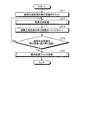
つぎに、このような構成の画像処理装置1での画像処理方法について説明する。図3は、実施形態による画像処理方法の手順の一例を示すフローチャートである。なお、ここでは、画像生成処理の繰り返し回数がM回(Mは自然数)に設定されているものとする。また、RAM13の所定のアドレスに、カメラなどの撮像装置によって撮像されたオリジナル画像が記憶された状態にあるものとする。
Next, an image processing method in the
まず、RAM13にオリジナル画像が記憶されると、CPU12は、画像生成処理の実行回数をカウントするカウンタをリセットする(ステップS11)。ついで、CPU12は、RAM13に記憶されたオリジナル画像について、画像生成処理の実行をDSP11に指示し、DSP11は、画像生成処理を実行する(ステップS12)。
First, when the original image is stored in the
図4は、画像生成処理の手順の一例を示すフローチャートである。まず、DSP11の読込部111は、RAM13の所定のアドレスから画像データを読み込む(ステップS31)。この画像データは、フィルタ処理が施されていないオリジナル画像である。カウンタの値が0の場合には、RAM13に記憶されている画像データは、たとえば撮像装置で撮像されたオリジナル画像である。また、カウンタの値が0以外の場合には、RAM13に記憶されている画像データは、前回の画像生成処理で生成された最小のスケールの縮小画像である。
FIG. 4 is a flowchart showing an example of the procedure of the image generation processing. First, the reading unit 111 of the
ついで、DSP11のフィルタ部113は、読み込んだオリジナル画像について、フィルタ処理を行い、フィルタ画像を生成する(ステップS32)。その後、DSP11の書込部114は、フィルタ処理されたフィルタ画像を、RAM13の所定のアドレスに書き込む(ステップS33)。
Next, the filter unit 113 of the
また、DSP11の縮小部112は、読み込んだオリジナル画像から異なるN枚のスケールの縮小画像を生成する(ステップS34)。上記したように、スケールは、任意の値とすることができる。最小のスケールの縮小画像以外のN−1枚の縮小画像について、DSP11のフィルタ部113は、フィルタ処理を行い、フィルタ画像を生成する(ステップS35)。その後、DSP11の書込部114は、フィルタ処理されたN−1枚のフィルタ画像を、RAM13の所定のアドレスに書き込む(ステップS36)。一方、最小のスケールの縮小画像については、ステップS34で縮小画像が生成された後、書込部114は、RAM13の所定のアドレスに縮小画像を書き込む(ステップS37)。
Further, the reduction unit 112 of the
なお、オリジナル画像のステップS32〜S33の処理と、最小のスケールの縮小画像以外のステップS34〜S36の処理と、最小のスケールの縮小画像のステップS34,S37の処理とは、並行して実行される。以上によって、画像生成処理が終了し、図3のフローチャートに処理が戻る。 The processing of steps S32 to S33 of the original image, the processing of steps S34 to S36 other than the reduced image of the minimum scale, and the processing of steps S34 and S37 of the reduced image of the minimum scale are executed in parallel. To. As a result, the image generation process is completed, and the process returns to the flowchart of FIG.
その後、RAM13の所定のアドレスにフィルタ画像と縮小画像とが書き込まれると、CPU12は、カウンタを1インクリメントする(ステップS13)。すなわち、画像生成処理の実行回数が1インクリメントされる。
After that, when the filter image and the reduced image are written to the predetermined address of the
ついで、CPU12は、カウンタの値が繰り返し回数Mよりも小さいかを判定する(ステップS14)。カウンタの値が繰り返し回数Mよりも小さい場合(ステップS14でYesの場合)には、ステップS12へと処理が戻る。この場合には、前回の画像生成処理で、RAM13に書き込まれた最小のスケールの縮小画像について、画像生成処理が行われることになる。すなわち、CPU12は、RAM13に書き込まれた最小のスケールの縮小画像を読み込むようにDSP11に指示を与えて、上記した図4の処理が行われる。
Then, the CPU 12 determines whether the value of the counter is smaller than the number of repetitions M (step S14). If the value of the counter is smaller than the number of repetitions M (Yes in step S14), the process returns to step S12. In this case, in the previous image generation process, the image generation process is performed on the reduced image of the smallest scale written in the
一方、カウンタの値が繰り返し回数Mと同じである場合(ステップS14でNoの場合)には、最終画像フィルタ処理を実行する(ステップS15)。 On the other hand, when the value of the counter is the same as the number of repetitions M (No in step S14), the final image filter processing is executed (step S15).
図5は、最終画像フィルタ処理の手順の一例を示すフローチャートである。まず、DSP11の読込部111は、RAM13の所定のアドレスから画像データを読み込む(ステップS51)。ここでは、直前の画像生成処理で最小のスケールの縮小画像が書き込まれたアドレスがCPU12からDSP11に通知され、DSP11は通知されたアドレスから最小のスケールの縮小画像を読み込む。ついで、DSP11のフィルタ部113は、読み込んだ最小のスケールの縮小画像にフィルタ処理を行い、フィルタ画像を生成する(ステップS52)。そして、DSP11の書込部114は、生成されたフィルタ画像をRAM13の所定のアドレスに書き込む(ステップS53)。以上によって、最終画像フィルタ処理が終了し、また図3のフローチャートも終了する。
FIG. 5 is a flowchart showing an example of the procedure of the final image filtering process. First, the reading unit 111 of the
なお、上記した説明では、CPU12が、画像生成処理の実行回数をカウントする機能を有しているが、画像処理部であるDSP11に画像生成処理の実行回数をカウントする機能(カウント部)を設けてもよい。
In the above description, the CPU 12 has a function of counting the number of times the image generation process is executed, but the
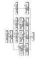
つぎに、画像処理方法の概要について説明する。図6−1〜図7−2は、実施形態による画像処理方法の手順の一例を模式的に示す図である。この説明では、DSP11がオリジナル画像から5枚のスケールの異なる縮小画像を生成する場合を例に挙げる。また、図6−1〜図6−2は、繰り返し回数が1回の場合を示し、図7−1〜図7−2は、繰り返し回数が複数回の場合を示している。また、以下では、1回の画像形成処理で5枚の縮小画像が生成される場合を例に挙げる。
Next, an outline of the image processing method will be described. 6-1 to 7-2 are diagrams schematically showing an example of the procedure of the image processing method according to the embodiment. In this description, the case where the
<繰り返し回数が1回の場合>
図6−1(a)に示されるように、DSP11の読込部111は、バス15を介して、オリジナル画像201aをRAM13から読み込む。ついで、図6−1(b)に示されるように、DSP11の縮小部112は、オリジナル画像201aから異なる倍率の5枚の縮小画像202a〜206aを生成する。すなわち、オリジナル画像201aに対して、R1倍の縮小画像202a、R2倍の縮小画像203a、R3倍の縮小画像204a、R4倍の縮小画像205aおよびR5倍の縮小画像206aが生成される。
<When the number of repetitions is 1>
As shown in FIG. 6-1 (a), the reading unit 111 of the
その後、図6−1(c)に示されるように、DSP11の書込部114は、バス15を介して、最小のスケールの縮小画像206aをRAM13の所定のアドレスに書き込む。
After that, as shown in FIG. 6-1 (c), the
また、これと並行して、図6−1(d)に示されるように、DSP11のフィルタ部113は、最小のスケールの縮小画像206aを除く縮小画像202a〜205aおよびオリジナル画像201aのそれぞれについて、フィルタ処理を行う。これによって、フィルタ画像201b〜205bが生成される。そして、図6−2(e)に示されるように、DSP11の書込部114は、バス15を介して、生成したフィルタ画像201b〜205bをRAM13の所定のアドレスに書き込む。
In parallel with this, as shown in FIG. 6-1 (d), the filter unit 113 of the
この例では、繰り返し回数が1回であるので、以上が画像生成処理になる。その後、最終画像フィルタ処理が行われる。図6−2(f)に示されるように、DSP11の読込部111は、バス15を介して、最小のスケールの縮小画像206aを読み込む。ついで、図6−2(g)に示されるように、DSP11のフィルタ部113は、読み込んだ縮小画像206aについてフィルタ処理を施してフィルタ画像206bを生成する。そして、図6−2(h)に示されるように、DSP11の書込部114は、バス15を介して、生成したフィルタ画像206bをRAM13の所定のアドレスに書き込む。以上によって、オリジナル画像と等倍のフィルタ画像を含む6枚のフィルタ画像が得られる。
In this example, since the number of repetitions is one, the above is the image generation process. After that, the final image filtering process is performed. As shown in FIG. 6-2 (f), the reading unit 111 of the
<繰り返し回数が複数回の場合>
繰り返し回数が複数回の場合でも、繰り返し回数が1回の場合の図6−1(a)〜図6−2(e)と同様である。その後、図示しないCPU12によって繰り返し回数がカウントされ、図7−1(a)に示されるように、DSP11の読込部111は、バス15を介して、前回の画像生成処理で最小のスケールの縮小画像206aが書き込まれたRAM13のアドレスから縮小画像206aを読み込む。すなわち、縮小画像206aが新たなオリジナル画像となる。
<When the number of repetitions is multiple>
Even when the number of repetitions is a plurality of times, it is the same as in FIGS. 6-1 (a) to 6-2 (e) when the number of repetitions is one. After that, the number of repetitions is counted by a CPU 12 (not shown), and as shown in FIG. 7-1 (a), the reading unit 111 of the
ついで、図7−1(b)に示されるように、DSP11の縮小部112は、オリジナル画像206aから異なる倍率の5枚の縮小画像207a〜211aを生成する。すなわち、オリジナル画像206aに対して、R1倍の縮小画像207a、R2倍の縮小画像208a、R3倍の縮小画像209a、R4倍の縮小画像210aおよびR5倍の縮小画像211aが生成される。なお、ここで生成される縮小画像207a〜211aは、それぞれ元のオリジナル画像201aのR5×R1倍、R5×R2倍、R5×R3倍、R5×R4倍、R5×R5倍となる。
Then, as shown in FIG. 7-1 (b), the reduction unit 112 of the
その後、図7−1(c)に示されるように、DSP11の書込部114は、バス15を介して、最小のスケールの縮小画像211aをRAM13の所定のアドレスに書き込む。
After that, as shown in FIG. 7-1 (c), the
また、これと並行して、図7−1(d)に示されるように、DSP11のフィルタ部113は、最小のスケールの縮小画像211aを除く縮小画像207a〜210aおよびオリジナル画像206aのそれぞれについて、フィルタ処理を行う。これによって、フィルタ画像206b〜210bが生成される。そして、図7−2(e)に示されるように、DSP11の書込部114は、バス15を介して、生成したフィルタ画像206b〜210bをRAM13の所定のアドレスに書き込む。
In parallel with this, as shown in FIG. 7-1 (d), the filter unit 113 of the
繰り返し回数が3回以上の場合には、図7−1(a)〜図7−2(e)が繰り返し回数分だけ行われることになる。ここでは、繰り返し回数が2回であるとする。そして、繰り返し回数が設定された回数になると、図7−2(f)に示されるように、DSP11の読込部111は、バス15を介して、最小のスケールの縮小画像211aを読み込む。ついで、図7−2(g)に示されるように、DSP11のフィルタ部113は、読み込んだ縮小画像211aについてフィルタ処理を施してフィルタ画像211bを生成する。そして、図7−2(h)に示されるように、DSP11の書込部114は、バス15を介して、生成したフィルタ画像211bをRAM13の所定のアドレスに書き込む。以上によって、図6−1(a)で読み込まれたオリジナル画像201aと等倍のフィルタ画像201bを含む11枚のフィルタ画像201b〜211bが得られる。
When the number of repetitions is 3 or more, FIGS. 7-1 (a) to 7-2 (e) are repeated for the number of repetitions. Here, it is assumed that the number of repetitions is two. Then, when the number of repetitions reaches the set number of times, as shown in FIG. 7-2 (f), the reading unit 111 of the
ここで、比較例と比較した本実施形態の効果について説明する。図8−1〜図8−2は、比較例による画像処理方法の手順の一例を模式的に示す図である。この説明では、DSP11がオリジナル画像から5枚のスケールの異なる縮小画像を生成する場合を例に挙げる。
Here, the effect of the present embodiment compared with the comparative example will be described. 8-1 to 8-2 are diagrams schematically showing an example of the procedure of the image processing method according to the comparative example. In this description, the case where the
図8−1(a)に示されるように、DSP11は、バス15を介して、オリジナル画像201aをRAM13から読み込む。ついで、図8−1(b)に示されるように、DSP11は、オリジナル画像201aから異なる倍率の5枚の縮小画像202a〜206aを生成する。すなわち、オリジナル画像201aに対して、R1倍の縮小画像202a、R2倍の縮小画像203a、R3倍の縮小画像204a、R4倍の縮小画像205aおよびR5倍の縮小画像206aが生成される。
As shown in FIG. 8-1 (a), the
その後、図8−1(c)に示されるように、DSP11は、バス15を介して、最小のスケールの縮小画像206aをRAM13の所定のアドレスに書き込む。
Then, as shown in FIG. 8-1 (c), the
また、これと並行して、図8−1(d)に示されるように、DSP11は、縮小画像202a〜206aのそれぞれについて、フィルタ処理を行う。これによって、フィルタ画像202b〜206bが生成される。そして、図8−2(e)に示されるように、DSP11は、バス15を介して、生成したフィルタ画像202b〜206bをRAM13の所定のアドレスに書き込む。
In parallel with this, as shown in FIG. 8-1 (d), the
繰り返し回数が1回である場合には、その後、図8−2(f)に示されるように、DSP11は、バス15を介して、図8−1(a)で読み込んだものと同じオリジナル画像201aを読み込む。ついで、図8−2(g)に示されるように、DSP11は、読み込んだオリジナル画像201aについてフィルタ処理を施してフィルタ画像201bを生成する。そして、図8−2(h)に示されるように、DSP11は、バス15を介して、生成したフィルタ画像201bをRAM13の所定のアドレスに書き込む。以上によって、オリジナル画像と等倍のフィルタ画像を含む6枚のフィルタ画像が得られる。
When the number of repetitions is one, then, as shown in FIG. 8-2 (f), the
図8−1(a)および図8−2(f)に示されるように、比較例では、RAM13からDSP11へと、バス15を介して、縮小画像と比較するとサイズの大きいオリジナル画像201aが2回読み込まれている。そのため、画像処理に時間がかかるとともに、転送時にバス15に負荷がかかってしまう。
As shown in FIGS. 8-1 (a) and 8-2 (f), in the comparative example, the
一方、本実施形態では、繰り返し回数が1回の場合には、RAM13からDSP11へと、バス15を介して、オリジナル画像201aを転送した後、最終画像フィルタ処理の際には、RAM13からDSP11へと、バス15を介して、オリジナル画像を縮小したもののうち最小のスケールの縮小画像を転送する。つまり、比較例と比較して、2回目に送信する画像データのサイズが小さくなる。そのため、画像データの転送に要する時間、すなわち画像処理にかかる時間を比較例に比して短縮することができ、かつ転送時のバス15にかかる負荷を比較例に比して低減できるという効果を得ることができる。
On the other hand, in the present embodiment, when the number of repetitions is one, the
本実施形態の画像処理装置で実行される画像処理プログラムは、インストール可能な形式または実行可能な形式のファイルでCD(Compact Disc)−ROM、フレキシブルディスク(FD)、CD−R(recordable)、DVD(Digital Versatile Disk)等のコンピュータで読み取り可能な記録媒体に記録されて提供される。 The image processing program executed by the image processing apparatus of the present embodiment is a file in an installable format or an executable format, and is a CD (Compact Disc) -ROM, a flexible disk (FD), a CD-R (recordable), or a DVD. It is recorded and provided on a computer-readable recording medium such as (Digital Versatile Disk).
また、本実施形態の画像処理装置で実行される画像処理プログラムを、インターネット等のネットワークに接続されたコンピュータ上に格納し、ネットワーク経由でダウンロードさせることにより提供するように構成してもよい。さらに、本実施形態の画像処理装置で実行される画像処理プログラムをインターネット等のネットワーク経由で提供または配布するように構成してもよい。 Further, the image processing program executed by the image processing device of the present embodiment may be stored on a computer connected to a network such as the Internet and provided by downloading via the network. Further, the image processing program executed by the image processing apparatus of the present embodiment may be configured to be provided or distributed via a network such as the Internet.
また、本実施形態の画像処理プログラムを、ROM等に予め組み込んで提供するように構成してもよい。 Further, the image processing program of the present embodiment may be configured to be provided by incorporating it into a ROM or the like in advance.
本実施の形態の画像処理装置で実行される画像処理プログラムは、上述した各部(読込部111、縮小部112、フィルタ部113および書込部114)を含むモジュール構成となっており、実際のハードウェアとしてはDSP11(プロセッサ)が上記記憶媒体から画像処理プログラムを読み出して実行することにより上記各部が主記憶装置上にロードされ、読込部111、縮小部112、フィルタ部113および書込部114が主記憶装置上に生成されるようになっている。
The image processing program executed by the image processing device of the present embodiment has a module configuration including the above-mentioned parts (reading unit 111, reduction unit 112, filter unit 113, and writing unit 114), and is an actual hardware. As hardware, when the DSP 11 (processor) reads the image processing program from the storage medium and executes it, each of the above parts is loaded on the main storage device, and the reading unit 111, the reduction unit 112, the filter unit 113, and the
また、上記した説明では、DSP11が画像処理プログラムを読み込んで、上記した画像処理方法を実行する場合を説明した。しかし、DSP11に代えて、上記した画像処理方法をソフトウェアではなくハードウェアで実行するIPA(Image Processing Accelerator)を用いてもよい。IPAは、画像処理方法を実行する回路によって構成される。
Further, in the above description, the case where the
本発明のいくつかの実施形態を説明したが、これらの実施形態は、例として提示したものであり、発明の範囲を限定することは意図していない。これら新規な実施形態は、その他の様々な形態で実施されることが可能であり、発明の要旨を逸脱しない範囲で、種々の省略、置き換え、変更を行うことができる。これら実施形態やその変形は、発明の範囲や要旨に含まれるとともに、特許請求の範囲に記載された発明とその均等の範囲に含まれる。 Although some embodiments of the present invention have been described, these embodiments are presented as examples and are not intended to limit the scope of the invention. These novel embodiments can be implemented in various other embodiments, and various omissions, replacements, and changes can be made without departing from the gist of the invention. These embodiments and modifications thereof are included in the scope and gist of the invention, and are also included in the scope of the invention described in the claims and the equivalent scope thereof.
1 画像処理装置、11 DSP、12 CPU、13 RAM、14 ROM、15 バス、111 読込部、112 縮小部、113 フィルタ部、114 書込部。 1 Image processing device, 11 DSP, 12 CPU, 13 RAM, 14 ROM, 15 bus, 111 reading unit, 112 reduction unit, 113 filter unit, 114 writing unit.
Claims (9)
前記メモリから読み込んだ前記画像の縮小またはフィルタ処理を行う画像処理部と、
前記メモリと前記画像処理部との間で前記画像を転送するバスと、
を備え、
前記画像処理部は、
画像生成処理では、前記メモリから第1画像を読み込み、前記第1画像からスケールの異なるN枚(Nは2以上の自然数)の縮小画像を生成し、前記縮小画像のうち最小のスケールの第1縮小画像を前記メモリに書き込み、前記縮小画像のうち前記第1縮小画像を除いた第2縮小画像および前記第1画像に前記フィルタ処理を行って第1フィルタ画像を生成し、前記メモリに書き込み、
最終画像フィルタ処理では、前記メモリから前記第1縮小画像を読み込み、前記フィルタ処理を行って第2フィルタ画像を生成し、前記メモリに書き込むことを特徴とする画像処理装置。 Memory for storing images and
An image processing unit that reduces or filters the image read from the memory, and
A bus that transfers the image between the memory and the image processing unit,
With
The image processing unit
In the image generation process, the first image is read from the memory, N reduced images having different scales (N is a natural number of 2 or more) are generated from the first image, and the first of the smallest scales of the reduced images is generated. The reduced image is written to the memory, the second reduced image excluding the first reduced image and the first image are subjected to the filtering process to generate a first filter image, and the reduced image is written to the memory.
In the final image filtering process, an image processing apparatus characterized in that the first reduced image is read from the memory, the filtering process is performed to generate a second filter image, and the image is written to the memory.
前記メモリから読み込んだ前記画像の縮小またはフィルタ処理を行う画像処理部と、
前記メモリと前記画像処理部との間で前記画像を転送するバスと、
を備える画像処理装置で実行される画像処理方法であって、
前記メモリから第1画像を読み込む第1読込工程と、
前記第1画像からスケールの異なるN枚(Nは2以上の自然数)の縮小画像を生成する第1縮小画像生成工程と、
前記縮小画像のうち最小のスケールの第1縮小画像を前記メモリに書き込む第1書込工程と、
前記縮小画像のうち前記第1縮小画像を除いた第2縮小画像および前記第1画像に前記フィルタ処理を行って第1フィルタ画像を生成する第1フィルタ画像生成工程と、
前記第1フィルタ画像を前記メモリに書き込む第2書込工程と、
前記メモリから前記第1縮小画像を読み込む第2読込工程と、
前記第1縮小画像に対して前記フィルタ処理を行って第2フィルタ画像を生成する第2フィルタ画像生成工程と、
前記第2フィルタ画像を前記メモリに書き込む第3書込工程と、
を含むことを特徴とする画像処理方法。 Memory for storing images and
An image processing unit that reduces or filters the image read from the memory, and
A bus that transfers the image between the memory and the image processing unit,
An image processing method executed by an image processing apparatus including
The first reading step of reading the first image from the memory and
The first reduced image generation step of generating N reduced images (N is a natural number of 2 or more) having different scales from the first image, and
A first writing step of writing the first reduced image of the smallest scale among the reduced images to the memory, and
A first filter image generation step of performing the filter processing on the second reduced image excluding the first reduced image and the first image to generate a first filter image among the reduced images.
A second writing step of writing the first filter image to the memory, and
A second reading step of reading the first reduced image from the memory, and
A second filter image generation step of performing the filter processing on the first reduced image to generate a second filter image, and
A third writing step of writing the second filter image to the memory, and
An image processing method characterized by including.
前記実行回数が予め定められた繰り返し回数となったかを判定する判定工程と、
をさらに含み、
前記実行回数が予め定められた繰り返し回数未満の場合には、前記第1読込工程から前記第2書込工程までの処理を実行し、
前記実行回数が予め定められた繰り返し回数となった場合に、前記第2読込工程以降の処理を実行することを特徴とする請求項5に記載の画像処理方法。 A counting process that counts the number of times the process is executed from the first reading process to the second writing process, and
A determination step for determining whether the number of executions has reached a predetermined number of repetitions, and
Including
When the number of executions is less than the predetermined number of repetitions, the processes from the first reading step to the second writing step are executed.
The image processing method according to claim 5, wherein when the number of executions reaches a predetermined number of repetitions, the processing after the second reading step is executed.
前記第1読込工程で読み込まれる前記第1画像は、直前の前記第1書込工程で書き込まれた前記第1縮小画像であり、
前記第2読込工程では、直前の前記第1書込工程で書き込まれた前記第1縮小画像を読み込むことを特徴とする請求項8に記載の画像処理方法。 When the number of executions is 2 or more,
The first image read in the first reading step is the first reduced image written in the first writing step immediately before.
The image processing method according to claim 8, wherein in the second reading step, the first reduced image written in the first writing step immediately before is read.
Priority Applications (3)
| Application Number | Priority Date | Filing Date | Title |
|---|---|---|---|
| JP2017177399A JP6783732B2 (en) | 2017-09-15 | 2017-09-15 | Image processing device and image processing method |
| CN201810148834.5A CN109509147A (en) | 2017-09-15 | 2018-02-13 | Image processing apparatus and image processing method |
| US15/899,476 US20190087931A1 (en) | 2017-09-15 | 2018-02-20 | Image processing apparatus and image processing method |
Applications Claiming Priority (1)
| Application Number | Priority Date | Filing Date | Title |
|---|---|---|---|
| JP2017177399A JP6783732B2 (en) | 2017-09-15 | 2017-09-15 | Image processing device and image processing method |
Publications (2)
| Publication Number | Publication Date |
|---|---|
| JP2019053524A JP2019053524A (en) | 2019-04-04 |
| JP6783732B2 true JP6783732B2 (en) | 2020-11-11 |
Family
ID=65720499
Family Applications (1)
| Application Number | Title | Priority Date | Filing Date |
|---|---|---|---|
| JP2017177399A Active JP6783732B2 (en) | 2017-09-15 | 2017-09-15 | Image processing device and image processing method |
Country Status (3)
| Country | Link |
|---|---|
| US (1) | US20190087931A1 (en) |
| JP (1) | JP6783732B2 (en) |
| CN (1) | CN109509147A (en) |
Families Citing this family (1)
| Publication number | Priority date | Publication date | Assignee | Title |
|---|---|---|---|---|
| CN113298823B (en) * | 2021-05-20 | 2024-03-15 | 西安锐思数智科技股份有限公司 | Image fusion method and device |
Family Cites Families (17)
| Publication number | Priority date | Publication date | Assignee | Title |
|---|---|---|---|---|
| US5471320A (en) * | 1994-05-11 | 1995-11-28 | Xerox Corporation | Stack filters for 1-to-N bit image processing in electronic printers |
| US5547132A (en) * | 1994-10-20 | 1996-08-20 | Calmar Inc. | Sprayer having variable spray pattern |
| JP2001251624A (en) * | 2000-03-06 | 2001-09-14 | Canon Inc | Image processor, image processing method and computer readable memory |
| JP4561380B2 (en) * | 2005-01-24 | 2010-10-13 | コニカミノルタホールディングス株式会社 | Detection apparatus, detection method, and detection program |
| JP4832031B2 (en) * | 2005-09-08 | 2011-12-07 | オリンパスイメージング株式会社 | Image processing method and image processing apparatus |
| JP4926568B2 (en) * | 2006-06-29 | 2012-05-09 | キヤノン株式会社 | Image processing apparatus, image processing method, and image processing program |
| US7848597B2 (en) * | 2006-09-08 | 2010-12-07 | Telefonaktiebolaget Lm Ericsson (Publ) | Data processing |
| US8135230B2 (en) * | 2007-07-30 | 2012-03-13 | Dolby Laboratories Licensing Corporation | Enhancing dynamic ranges of images |
| TWI399088B (en) * | 2007-10-12 | 2013-06-11 | Sony Corp | Data processor, solid-state imaging device, imaging device, and electronic apparatus |
| JP4955616B2 (en) * | 2008-06-27 | 2012-06-20 | 富士フイルム株式会社 | Image processing apparatus, image processing method, and image processing program |
| US8508603B2 (en) * | 2009-04-10 | 2013-08-13 | Panasonic Corporation | Object detection device, object detection system, integrated circuit for object detection, and object detection method |
| JP5644444B2 (en) * | 2010-12-03 | 2014-12-24 | 富士通株式会社 | Image display device, image display method, and image processing device |
| JP5514132B2 (en) * | 2011-02-07 | 2014-06-04 | 日本放送協会 | Image reduction device, image enlargement device, and program thereof |
| JP2013041400A (en) * | 2011-08-15 | 2013-02-28 | Sony Corp | Image processing device, image processing method and program |
| US8995743B2 (en) * | 2011-10-19 | 2015-03-31 | Crown Equipment Corporation | Identifying and locating possible lines corresponding to pallet structure in an image |
| US9380245B1 (en) * | 2013-02-14 | 2016-06-28 | Rambus Inc. | Conditional-reset image sensor with analog counter array |
| US9378555B2 (en) * | 2013-11-06 | 2016-06-28 | Honeywell International Inc. | Enhanced outlier removal for 8 point algorithm used in camera motion estimation |
-
2017
- 2017-09-15 JP JP2017177399A patent/JP6783732B2/en active Active
-
2018
- 2018-02-13 CN CN201810148834.5A patent/CN109509147A/en not_active Withdrawn
- 2018-02-20 US US15/899,476 patent/US20190087931A1/en not_active Abandoned
Also Published As
| Publication number | Publication date |
|---|---|
| CN109509147A (en) | 2019-03-22 |
| JP2019053524A (en) | 2019-04-04 |
| US20190087931A1 (en) | 2019-03-21 |
Similar Documents
| Publication | Publication Date | Title |
|---|---|---|
| JP5784299B2 (en) | Data processing apparatus and image processing apparatus | |
| JP2008118306A5 (en) | ||
| US9313358B2 (en) | Image processing apparatus | |
| JP2017041727A5 (en) | Image processing apparatus, image processing method, and image processing program | |
| US9026697B2 (en) | Data processing apparatus | |
| JP6783732B2 (en) | Image processing device and image processing method | |
| US8648936B2 (en) | Image processing apparatus and image processing method | |
| JP2007048257A (en) | Signal processor | |
| US20090055816A1 (en) | Information processing apparatus, update method, and program | |
| US9652832B2 (en) | Image processing apparatus, image pickup apparatus, image processing method, and non-transitory computer-readable storage medium which perform image restoration processing | |
| JP2014107837A5 (en) | ||
| JP2016110622A5 (en) | Control device, lens device, image processing system, control method, image processing method, program, and storage medium | |
| US9779701B2 (en) | Image processing apparatus, image processing method, and imaging apparatus | |
| JP4602860B2 (en) | Image processing device | |
| JP6132610B2 (en) | Image processing apparatus and image processing method | |
| US8712194B1 (en) | System for non-destructive image processing | |
| JP2017076887A (en) | Image processing device, control method for the same and imaging device | |
| JP6677593B2 (en) | Image processing apparatus and control method thereof | |
| JP2020150489A5 (en) | ||
| JP4598623B2 (en) | Image processing device | |
| JP2016092483A (en) | Memory control circuit and image forming apparatus | |
| JP6273881B2 (en) | Image processing apparatus, image processing method, and program | |
| US20170053387A1 (en) | Image processing apparatus, image pickup apparatus, image processing method, and non-transitory computer-readable storage medium for correcting deterioration of image | |
| JP5007234B2 (en) | Image processing device | |
| JP6399891B2 (en) | Imaging device |
Legal Events
| Date | Code | Title | Description |
|---|---|---|---|
| A621 | Written request for application examination |
Free format text: JAPANESE INTERMEDIATE CODE: A621 Effective date: 20190723 |
|
| A977 | Report on retrieval |
Free format text: JAPANESE INTERMEDIATE CODE: A971007 Effective date: 20200807 |
|
| TRDD | Decision of grant or rejection written | ||
| A01 | Written decision to grant a patent or to grant a registration (utility model) |
Free format text: JAPANESE INTERMEDIATE CODE: A01 Effective date: 20200923 |
|
| A61 | First payment of annual fees (during grant procedure) |
Free format text: JAPANESE INTERMEDIATE CODE: A61 Effective date: 20201022 |
|
| R150 | Certificate of patent or registration of utility model |
Ref document number: 6783732 Country of ref document: JP Free format text: JAPANESE INTERMEDIATE CODE: R150 |