JP6781695B2 - Kit including guidance system and bone material removal device - Google Patents
Kit including guidance system and bone material removal device Download PDFInfo
- Publication number
- JP6781695B2 JP6781695B2 JP2017521086A JP2017521086A JP6781695B2 JP 6781695 B2 JP6781695 B2 JP 6781695B2 JP 2017521086 A JP2017521086 A JP 2017521086A JP 2017521086 A JP2017521086 A JP 2017521086A JP 6781695 B2 JP6781695 B2 JP 6781695B2
- Authority
- JP
- Japan
- Prior art keywords
- bone
- cannula
- removal device
- bone material
- shaft
- Prior art date
- Legal status (The legal status is an assumption and is not a legal conclusion. Google has not performed a legal analysis and makes no representation as to the accuracy of the status listed.)
- Active
Links
Images


Classifications
-
- A—HUMAN NECESSITIES
- A61—MEDICAL OR VETERINARY SCIENCE; HYGIENE
- A61B—DIAGNOSIS; SURGERY; IDENTIFICATION
- A61B17/00—Surgical instruments, devices or methods, e.g. tourniquets
- A61B17/16—Bone cutting, breaking or removal means other than saws, e.g. Osteoclasts; Drills or chisels for bones; Trepans
- A61B17/17—Guides or aligning means for drills, mills, pins or wires
- A61B17/1739—Guides or aligning means for drills, mills, pins or wires specially adapted for particular parts of the body
- A61B17/1764—Guides or aligning means for drills, mills, pins or wires specially adapted for particular parts of the body for the knee
-
- A—HUMAN NECESSITIES
- A61—MEDICAL OR VETERINARY SCIENCE; HYGIENE
- A61B—DIAGNOSIS; SURGERY; IDENTIFICATION
- A61B17/00—Surgical instruments, devices or methods, e.g. tourniquets
- A61B17/16—Bone cutting, breaking or removal means other than saws, e.g. Osteoclasts; Drills or chisels for bones; Trepans
- A61B17/17—Guides or aligning means for drills, mills, pins or wires
-
- A—HUMAN NECESSITIES
- A61—MEDICAL OR VETERINARY SCIENCE; HYGIENE
- A61B—DIAGNOSIS; SURGERY; IDENTIFICATION
- A61B17/00—Surgical instruments, devices or methods, e.g. tourniquets
- A61B17/16—Bone cutting, breaking or removal means other than saws, e.g. Osteoclasts; Drills or chisels for bones; Trepans
- A61B17/1613—Component parts
- A61B17/1615—Drill bits, i.e. rotating tools extending from a handpiece to contact the worked material
- A61B17/1617—Drill bits, i.e. rotating tools extending from a handpiece to contact the worked material with mobile or detachable parts
-
- A—HUMAN NECESSITIES
- A61—MEDICAL OR VETERINARY SCIENCE; HYGIENE
- A61B—DIAGNOSIS; SURGERY; IDENTIFICATION
- A61B17/00—Surgical instruments, devices or methods, e.g. tourniquets
- A61B17/16—Bone cutting, breaking or removal means other than saws, e.g. Osteoclasts; Drills or chisels for bones; Trepans
- A61B17/1662—Bone cutting, breaking or removal means other than saws, e.g. Osteoclasts; Drills or chisels for bones; Trepans for particular parts of the body
- A61B17/1675—Bone cutting, breaking or removal means other than saws, e.g. Osteoclasts; Drills or chisels for bones; Trepans for particular parts of the body for the knee
-
- A—HUMAN NECESSITIES
- A61—MEDICAL OR VETERINARY SCIENCE; HYGIENE
- A61B—DIAGNOSIS; SURGERY; IDENTIFICATION
- A61B17/00—Surgical instruments, devices or methods, e.g. tourniquets
- A61B17/16—Bone cutting, breaking or removal means other than saws, e.g. Osteoclasts; Drills or chisels for bones; Trepans
- A61B17/17—Guides or aligning means for drills, mills, pins or wires
- A61B17/1714—Guides or aligning means for drills, mills, pins or wires for applying tendons or ligaments
-
- A—HUMAN NECESSITIES
- A61—MEDICAL OR VETERINARY SCIENCE; HYGIENE
- A61B—DIAGNOSIS; SURGERY; IDENTIFICATION
- A61B17/00—Surgical instruments, devices or methods, e.g. tourniquets
- A61B17/16—Bone cutting, breaking or removal means other than saws, e.g. Osteoclasts; Drills or chisels for bones; Trepans
Description
関連出願
本出願は、2014年10月19日に出願された米国仮特許出願第62/065,701号の米国特許法第119条(e)に基づく優先権の利益を主張するものであり、その内容は、参照によりその全体が本明細書に組み込まれる。
Related Applications This application claims the benefit of priority under Section 119 (e) of the US Patent Act of US Provisional Patent Application No. 62 / 065,701 filed on October 19, 2014. Its contents are incorporated herein by reference in its entirety.
本明細書によって、2014年4月24日に出願された「BONE MATERIAL REMOVAL DEVICES AND METHODS」という名称のPCT特許出願第PCT/IL2014/050381号に対する参照がなされ、その開示は、参照によりその全体が本明細書に組み込まれる。 The present specification makes a reference to PCT patent application No. PCT / IL2014 / 050381, entitled "BONE MATERIAL REMOVAL DEVICES AND METHODS", filed April 24, 2014, the disclosure of which is in its entirety by reference. Incorporated herein.
本発明は、そのいくつかの実施形態では、誘導システムと骨材料除去デバイスとを含むキットおよび使用方法、たとえば、有効直径を変更する骨除去デバイスに関する。より詳細には、本発明は、関節鏡視下再建における使用のための、特に前十字靱帯再建(ACL)術において有用な、固定デバイスに関する。 The present invention relates to kits and methods of use, including, in some embodiments thereof, a induction system and a bone material removing device, eg, a bone removing device that modifies the effective diameter. More specifically, the present invention relates to a fixed device for use in arthroscopic reconstruction, especially in anterior cruciate ligament reconstruction (ACL) surgery.
いくつかの関節鏡視下術中、特に前十字靱帯再建(ACL再建)中に、損傷した前十字靱帯を置換するために、外科的組織移植片が膝に挿入されることが知られている。損傷した靱帯が膝から除去されてから、穿孔によって作製された穴を通して移植片が挿入される。 It is known that a surgical tissue graft is inserted into the knee to replace the injured anterior cruciate ligament during some arthroscopic procedures, especially during anterior cruciate ligament reconstruction (ACL reconstruction). The damaged ligament is removed from the knee before the implant is inserted through the hole created by the perforation.
大腿骨および/または脛骨を通して所定の寸法を有する孔を穿孔するために、さまざまな固定技法が用いられる。 Various fixation techniques are used to perforate holes of a given size through the femur and / or tibia.
たとえば、米国特許第5,112,337号は、「前十字靱帯置換のために脛骨内でトンネルを穿孔するためのドリル誘導子が、脛骨プラトー内のトンネルの出口と係合し、脛骨プラトーを決定するための突端を有する標的フックと、ドリル誘導子スリーブホルダとプラトーに対するホルダの角位置を調整し堅固に固定するための選択的に可変の手段とを担持するハンドルとを備える。このドリル誘導子は、その突端に向かっておよびそれから離れるように軸方向移動のためにホルダ内で長手方向に選択的に調整可能に受け入れられるドリルスリーブも備え、このドリルスリーブは、突端に向かって延びる近位端を有する。このドリルスリーブは、突端に向けられた鋭利な先端を有するガイドワイヤを受け入れるためにカニューレ状である(カニューレ処理される)。選択された位置においてドリルスリーブを保持するための係合手段が提供され、それによって、前記ドリルスリーブの近位端と突端との間に画定された所望のトンネル長をあらかじめ選択する」に関する。 For example, US Pat. No. 5,112,337 states that "a drill inductor for drilling a tunnel in the tibia for anterior cruciate ligament replacement engages with the exit of the tunnel in the tibial plateau to create a tibial plateau. The drill guide comprises a target hook having a tip for determining and a handle carrying a drill inductor sleeve holder and selectively variable means for adjusting the angular position of the holder with respect to the plateau and fixing it firmly. The child also features a drill sleeve that is selectively adjustable longitudinally within the holder for axial movement towards and away from its tip, which is proximal to extend towards the tip. Has an end. This drill sleeve is cannulated (canneled) to receive a guide wire with a sharp tip pointed at the tip. Engagement to hold the drill sleeve in a selected position. Means are provided, thereby preselecting the desired tunnel length defined between the proximal end and the tip of the drill sleeve. "
いくつかの例示的な実施形態によれば、誘導システムと骨材料除去デバイスとを含み、誘導カニューレと、長手方向シャフトを有し、長手方向に向けられた切断縁を有する半径方向に拡張可能な切断部分を長手方向シャフト上に備える骨材料除去デバイスと、この半径方向の拡張が、拡張可能な切断部分の長手方向位置における骨材料除去デバイスの横断面直径の増加を備える、を備え、ここにおいて、骨材料除去デバイスがカニューレ内で軸方向に変位可能である、キットが提供される。 According to some exemplary embodiments, it includes a guiding system and a bone material removal device, has a guiding cannula, a longitudinal shaft, and is radially expandable with a longitudinally oriented cutting edge. A bone material removing device comprising a cut portion on a longitudinal shaft, wherein this radial extension comprises an increase in the cross-sectional diameter of the bone material removal device in the longitudinal position of the expandable cut portion, wherein. A kit is provided in which the bone material removal device is axially displaceable within the cannula.
いくつかの実施形態によれば、このキットは、接続部材と、ここにおいて、誘導カニューレが、接続要素に取り付けられている間、長手方向に摺動可能である、ガイドアームの基端において接続部材要素に取り付け可能であり、別の端において末端構造を有するガイドアームと、ここにおいて、ガイドアームおよび前記要素が取り付けられるとき、末端構造が、長手方向に沿った領域に設置されるまたはこれを少なくとも部分的に取り囲む、をさらに備える。 According to some embodiments, the kit comprises a connecting member and, in this case, a connecting member at the proximal end of a guide arm that is longitudinally slidable while the induction cannula is attached to the connecting element. A guide arm that is attachable to an element and has a terminal structure at another end, and where, when the guide arm and said element are attached, the terminal structure is installed in a region along the longitudinal direction or at least this. Partially surrounding, further equipped.
いくつかの実施形態によれば、接続部材は、形状が円弧状である。 According to some embodiments, the connecting member is arcuate in shape.
いくつかの実施形態によれば、拡張可能な切断部分は、長手方向シャフトの遠位部分から半径方向に展開するように構成された少なくとも1つの切断歯を備える。 According to some embodiments, the expandable cut portion comprises at least one cut tooth configured to extend radially from the distal portion of the longitudinal shaft.
いくつかの実施形態によれば、拡張可能な切断部分は、長手方向シャフトに沿って延びるように向けられたヒンジ要素上で枢動することによって拡張する。 According to some embodiments, the expandable cut is expanded by pivoting on a hinge element directed to extend along a longitudinal shaft.
いくつかの実施形態によれば、誘導カニューレの内径は、カニューレ内で軸方向に変位可能な長手方向シャフトの一部分を嵌合式に受け入れるようなサイズにされる。 According to some embodiments, the inner diameter of the induction cannula is sized to fit into a portion of the longitudinal shaft that is axially displaceable within the cannula.
いくつかの実施形態によれば、長手方向シャフトは、直径が少なくとも4mmである。 According to some embodiments, the longitudinal shaft is at least 4 mm in diameter.
いくつかの実施形態によれば、長手方向シャフトと誘導カニューレの内径との間の隙間は、0.1mm未満である。 According to some embodiments, the clearance between the longitudinal shaft and the inner diameter of the induction cannula is less than 0.1 mm.
いくつかの実施形態によれば、骨材料除去デバイスは、カニューレ処置されている。 According to some embodiments, the bone material removal device has been cannulated.
いくつかの実施形態によれば、非拡張位置にある半径方向に拡張可能な切断部分は、非拡張の長手方向シャフトの任意の隣接する円周を越えて半径方向に拡張し、誘導カニューレの内径は、非拡張位置において拡張可能な切断部分を嵌合式に受け入れるようなサイズにされる。 According to some embodiments, the radially expandable cut in the non-expanded position extends radially beyond any adjacent circumference of the non-expanded longitudinal shaft and the inner diameter of the induction cannula. Is sized to fit into an expandable cut in a non-expandable position.
いくつかの実施形態によれば、キットは、軸方向変位の方向に沿ってカニューレ上で摺動可能に変位可能な少なくとも1つのストッパをさらに備える。 According to some embodiments, the kit further comprises at least one stopper that is slidably displaceable on the cannula along the direction of axial displacement.
いくつかの実施形態によれば、骨材料除去デバイスは、長手方向シャフトまで実質的に横断方向に延び、前記骨材料除去デバイスの長手方向の動程を制限するために少なくとも1つのストッパと接触するところに位置決めされるピンをさらに備える。 According to some embodiments, the bone material removal device extends substantially transversely to the longitudinal shaft and contacts at least one stopper to limit the longitudinal movement of the bone material removal device. Further provided with a pin positioned at the place.
いくつかの実施形態によれば、ピンが回転に関して静止している間、シャフトが自由に回転するように、ピンが、軸受けを回転させることによって長手方向シャフトに取り付けられる。 According to some embodiments, the pin is attached to the longitudinal shaft by rotating the bearing so that the shaft rotates freely while the pin is stationary with respect to rotation.
いくつかの実施形態によれば、ピンの長手方向位置は、長手方向シャフトに対して固定される。 According to some embodiments, the longitudinal position of the pin is fixed with respect to the longitudinal shaft.
いくつかの実施形態によれば、ストッパは、その中に形成され、ストッパがカニューレに取り付けられている間、それを通してピンの変位を可能にするようなサイズにされ、位置決め可能である、溝を含む。 According to some embodiments, the stopper is formed therein and is sized and positionable to allow displacement of the pin through it while the stopper is attached to the cannula. Including.
いくつかの実施形態によれば、末端構造は、少なくとも部分的に長手方向に沿って領域を取り囲み、円周の外部では骨材料除去デバイスの長手方向シャフトの直径を有する。 According to some embodiments, the end structure surrounds the region at least partially along the longitudinal direction and has the diameter of the longitudinal shaft of the bone material removal device outside the circumference.
いくつかの実施形態によれば、少なくとも部分的に取り囲むことは、骨材料除去デバイスの直径によって画定された円周の少なくとも33%のまわりに延びることを備える。 According to some embodiments, the encircling at least partially comprises extending around at least 33% of the circumference defined by the diameter of the bone material removing device.
いくつかの実施形態によれば、末端構造はフック型である。 According to some embodiments, the terminal structure is hook type.
いくつかの実施形態によれば、末端構造はフォーク型である。 According to some embodiments, the terminal structure is fork-shaped.
いくつかの実施形態によれば、誘導カニューレは、それに沿って長手方向に設けられた全体的な骨トンネル長を示す距離スケールを備え、このスケールは、カニューレの最も遠位の摺動可能な位置が、誘導カニューレの遠位先端と末端構造との間の最小距離を画定する基準位置を提供するようにマークされ、より大きい距離は、誘導カニューレの遠位端に向かって値を増加させることによってスケール上に示される。 According to some embodiments, the induction cannula comprises a distance scale along which is provided longitudinally to indicate the overall bone tunnel length, which scale is the most distal slidable position of the cannula. Is marked to provide a reference position that defines the minimum distance between the distal tip of the induction cannula and the distal structure, and larger distances are increased by increasing the value towards the distal end of the induction cannula. Shown on the scale.
いくつかの実施形態によれば、カニューレは、最小距離を画定する位置へのカニューレの遠位摺動運動を制限するために接続部材に干渉する広がりを備える。 According to some embodiments, the cannula comprises a spread that interferes with the connecting member in order to limit the distal sliding movement of the cannula to a position defining the minimum distance.
いくつかの実施形態によれば、スケールの距離は、カニューレおよびガイドアームの末端構造の相対位置によって画定された骨トンネルの実際の長さとしてマークされる。 According to some embodiments, the distance of the scale is marked as the actual length of the bone tunnel defined by the relative position of the terminal structure of the cannula and the guide arm.
いくつかの実施形態によれば、第2のスケールは骨材料除去デバイス上でマークされ、骨材料デバイスが近位方向に抜去されると逆方向の切断距離の標識を提供するためにマーク可能である。 According to some embodiments, the second scale is marked on the bone material removal device and can be marked to provide a sign of the reverse cutting distance when the bone material device is removed proximally. is there.
いくつかの実施形態によれば、2つのスケールは、骨材料除去デバイス上にマークされたスケール上の現在の距離示度が、骨トンネルの形成中に長手方向動程が制限されるべき骨材料除去デバイススケール上の位置を与えるように、協調される。 According to some embodiments, the two scales have the current distance reading on the scale marked on the bone material removal device, but the bone material whose longitudinal movement should be restricted during the formation of the bone tunnel. Coordinated to give position on the removal device scale.
いくつかの例示的な実施形態によれば、誘導システムと骨材料除去デバイスとを含み、誘導カニューレと、接続部材と、ここにおいて、誘導カニューレは、接続部材に取り付けられている間、長手方向に摺動可能である、ガイドアームの基端において接続部材に取り付け可能であり、別の端において末端構造を有するガイドアームと、ここにおいて、ガイドアームおよび接続部材が取り付けられるとき、末端構造が、長手方向に沿った領域に設置されるまたはこれを少なくとも部分的に取り囲む、カニューレ内で軸方向に変位可能な、長手方向シャフトを有するカニューレ処置された骨材料除去デバイスとを備えるキットが提供される。 According to some exemplary embodiments, the induction system and the bone material removal device include an induction cannula and a connecting member, wherein the induction cannula is longitudinally attached to the connecting member. A guide arm that is slidable, attachable to a connecting member at the base end of the guide arm and has a terminal structure at another end, and where the terminal structure is longitudinal when the guide arm and connecting member are attached. A kit is provided with a cannulated bone material removal device with a longitudinal shaft that is axially displaceable within the cannula and is installed in or at least partially surrounds the area along the direction.
いくつかの実施形態によれば、誘導カニューレの内径は、カニューレ内で軸方向に変位可能な長手方向シャフトの一部分を嵌合式に受け入れるようなサイズにされる。 According to some embodiments, the inner diameter of the induction cannula is sized to fit into a portion of the longitudinal shaft that is axially displaceable within the cannula.
いくつかの実施形態によれば、長手方向シャフトは、直径が少なくとも4mmである。 According to some embodiments, the longitudinal shaft is at least 4 mm in diameter.
いくつかの実施形態によれば、長手方向シャフトと誘導カニューレの内径との間の隙間は、0.1mm未満である。 According to some embodiments, the clearance between the longitudinal shaft and the inner diameter of the induction cannula is less than 0.1 mm.
いくつかの例示的な実施形態によれば、骨内に骨トンネルを穿孔する方法であって、骨上に誘導カニューレを位置決めすることと、このカニューレに骨材料除去デバイスを挿入することと、この骨材料除去デバイスを前進させながら、骨を通って順方向に骨トンネルを形成することと、骨材料除去デバイスの拡張可能な遠位部分を拡張することと、骨材料除去デバイスを抜去させながら、逆方向に骨トンネルを拡張することとを備え、ここにおいて、骨材料除去デバイスが、前進させることおよび抜去させることの間にそれぞれ反対方向に回転する、方法が提供される。 According to some exemplary embodiments, there is a method of perforating a bone tunnel into the bone, positioning the induction cannula on the bone and inserting a bone material removal device into the cannula. While advancing the bone removal device, forming a forward bone tunnel through the bone, expanding the expandable distal portion of the bone removal device, and removing the bone removal device. A method is provided in which the bone material removing device is rotated in opposite directions during advancing and withdrawal, respectively, comprising expanding the bone tunnel in the opposite direction.
いくつかの実施形態によれば、拡張可能な遠位部分は、骨材料除去デバイスの長手方向シャフトに沿って長手方向に向けられたヒンジ部材に枢動可能に取り付けられた切断歯を備える。 According to some embodiments, the expandable distal portion comprises a cutting tooth pivotally attached to a hinge member oriented longitudinally along the longitudinal shaft of the bone material removal device.
いくつかの実施形態の一態様によれば、誘導システムと骨材料除去デバイスとを含み、円弧状要素と、この円弧状要素に取り付けられるように構成された誘導要素と、円弧状要素の一部分に摺動可能に挿入可能なカニューレと、このカニューレ内で軸方向に変位可能な、長手方向シャフトを有するカニューレ処置された骨材料除去デバイスとを含むキットが提供される。 According to one aspect of some embodiments, the induction system and the bone material removing device are included in an arcuate element, an arcuate element configured to be attached to the arcuate element, and a portion of the arcuate element. A kit is provided that includes a slidably insertable cannula and a cannulated bone material removal device with a longitudinal shaft that is axially displaceable within the cannula.
好ましくは、カニューレ上で摺動可能に変位可能なストッパがある。このストッパは、好ましくは、その中に形成された溝を含む。 Preferably, there is a stopper that is slidably displaceable on the cannula. The stopper preferably includes a groove formed therein.
本発明のいくつかの実施形態では、骨材料除去デバイスは、長手方向シャフトまで実質的に横断方向に延びるピンをさらに含む。好ましくは、ピンは、ストッパの溝を通って変位可能である。 In some embodiments of the invention, the bone material removal device further comprises a pin that extends substantially transversely to the longitudinal shaft. Preferably, the pin is displaceable through the groove of the stopper.
本発明のいくつかの実施形態では、骨材料除去デバイスは、拡張可能な切断歯を有する。 In some embodiments of the invention, the bone material removing device has expandable cutting teeth.
いくつかの実施形態の一態様によれば、細長いシャフトと、骨内の孔を広げるための少なくとも1つの骨材料除去要素と、この要素はシャフトに結合され、この要素は、この要素がシャフト内で部分的にのみ受け入れられる閉位置からこの要素がシャフトから半径方向に遠ざかるように延びる開位置に移動可能である、を備え、ここにおいて、シャフトは、略円筒状の回転のボリュームを画定する断面を備え、骨除去要素の少なくとも一部分が、要素が閉位置にあるとき、回転のボリュームを越えて延びる、骨材料除去デバイスが提供される。 According to one aspect of some embodiments, an elongated shaft and at least one bone material removing element for widening a hole in the bone, this element is coupled to the shaft, which element is this element within the shaft. The element is movable from a closed position, which is only partially accepted in, to an open position, which extends radially away from the shaft, where the shaft defines a substantially cylindrical volume of rotation. Provided is an osteomaterial removal device comprising, at least a portion of the bone removal element extending beyond the volume of rotation when the element is in the closed position.
いくつかの実施形態では、骨材料除去要素は、ヒンジによってシャフトに結合された枢動可能な切断歯である。 In some embodiments, the bone material removing element is a pivotable cutting tooth that is hinged to the shaft.
いくつかの実施形態では、骨除去要素の部分は、閉位置にあるとき、シャフトの回転のボリュームから0.05mmから0.5mmの間の距離範囲ではみ出る。 In some embodiments, the portion of the bone removal element protrudes from the volume of rotation of the shaft in a distance range of between 0.05 mm and 0.5 mm when in the closed position.
いくつかの実施形態では、切断歯は、凹所とともに形成された切断面を備える。任意選択で、凹所の湾曲の半径は、1.5mm〜4mmに及ぶ。 In some embodiments, the cut tooth comprises a cut surface formed with a recess. Optionally, the radius of curvature of the recess ranges from 1.5 mm to 4 mm.
いくつかの実施形態では、切断歯は、平坦な部分とともに形成された切断面を備える。 In some embodiments, the cut tooth comprises a cut surface formed with a flat portion.
いくつかの実施形態では、歯は、デバイスの回転方向の逆転の結果として開くために、ヒンジ上で自由に枢動する。 In some embodiments, the teeth are free to pivot on the hinges to open as a result of the rotational reversal of the device.
いくつかの実施形態では、ヒンジは、ヒンジをシャフトにしっかりと取り付けるためにシャフト内で受け入れられる近位の細長い延長部と遠位の細長い延長部とを備える。 In some embodiments, the hinge comprises a proximal elongated extension and a distal elongated extension that are accepted within the shaft to securely attach the hinge to the shaft.
いくつかの実施形態では、シャフトは、歯の少なくとも一部分を受け入れるための形状およびサイズにされた凹部を備え、この凹部は、歯の回転運動を制限するような形状にされる。 In some embodiments, the shaft comprises a recess shaped and sized to accommodate at least a portion of the tooth, which recess is shaped to limit rotational movement of the tooth.
いくつかの実施形態では、デバイスはドリルビットであり、シャフトは1つまたは複数の縦溝(flute)を備える。 In some embodiments, the device is a drill bit and the shaft comprises one or more flutes.
いくつかの実施形態では、歯の切断面における凹所は、引き出された骨材料の除去のためのさらなる経路を提供するために、歯が開いているとき、シャフトの縦溝から直径に沿って対向する方向に面する。 In some embodiments, the recess in the cut surface of the tooth is along the diameter from the longitudinal groove of the shaft when the tooth is open to provide an additional path for removal of the extracted bone material. Facing in opposite directions.
いくつかの実施形態では、切断歯の底部表面は、骨表面の不規則な外形と係合するように非平面である。 In some embodiments, the bottom surface of the cut tooth is non-planar so as to engage the irregularities of the bone surface.
いくつかの実施形態では、シャフトは、尖った遠位先端を有するテーパのついたヘッドを備える。 In some embodiments, the shaft comprises a tapered head with a pointed distal tip.
いくつかの実施形態では、骨除去要素は、シャフトの長手方向軸と平行して延びる少なくとも1つの支持要素を含み、シャフトへの骨除去要素の枢動可能な接続を提供する。 In some embodiments, the bone removal element comprises at least one support element extending parallel to the longitudinal axis of the shaft to provide a pivotable connection of the bone removal element to the shaft.
いくつかの実施形態では、骨除去要素は、ヒンジピンまたは前記支持要素のうちの少なくとも1つによってシャフトに非可動的に(irremovably)取り付けられる。 In some embodiments, the bone removal element is immovably attached to the shaft by a hinge pin or at least one of said support elements.
いくつかの実施形態では、骨除去要素は、遠心力により、回転するとシャフトから拡張する。 In some embodiments, the bone removal element expands from the shaft as it rotates due to centrifugal force.
いくつかの実施形態では、骨除去要素は、シャフトの長手方向軸に垂直に延びる。 In some embodiments, the bone removal element extends perpendicular to the longitudinal axis of the shaft.
いくつかの実施形態では、デバイスは、骨除去要素が閉位置にある回転方向を有する孔穿孔構成で動作するように適合される。 In some embodiments, the device is adapted to operate in a perforated configuration with a rotational direction in which the bone removal element is in a closed position.
いくつかの実施形態では、デバイスは、骨除去要素が開位置にある孔を広げる構成で動作するように適合される。任意選択で、この構成は、回転の方向を選択することによって選択される。 In some embodiments, the device is adapted to operate in a configuration in which the bone removal element widens the hole in the open position. Optionally, this configuration is selected by selecting the direction of rotation.
いくつかの実施形態では、デバイスは、ガイドワイヤ上に挿入されるようにカニューレ処置される。 In some embodiments, the device is cannulated to be inserted onto a guide wire.
いくつかの実施形態では、骨除去要素は、開位置にあるとき、回転のボリュームを越えて少なくとも2mm拡張する。 In some embodiments, the bone removal element extends at least 2 mm beyond the volume of rotation when in the open position.
いくつかの実施形態では、デバイスはリーマーである。 In some embodiments, the device is a reamer.
いくつかの実施形態では、デバイスは、複数の切断歯を備える。 In some embodiments, the device comprises a plurality of cutting teeth.
いくつかの実施形態では、デバイスは、閉位置において骨除去要素がシャフトへとさらに入ることに抵抗するために構成された少なくとも1つの構造を備える。 In some embodiments, the device comprises at least one structure configured to resist further entry of the bone removal element into the shaft in the closed position.
いくつかの実施形態では、前記骨除去要素がシャフトへとさらに入ることに抵抗する構造は、この要素が受け入れられるシャフト内の凹部の1つまたは複数の壁である。 In some embodiments, the structure that resists further entry of the bone removal element into the shaft is one or more walls of a recess in the shaft where this element is accepted.
いくつかの実施形態では、構造は、骨除去要素がシャフトへと押し込まれてシャフト内に完全に隠されることを可能にする弾性要素である。 In some embodiments, the structure is an elastic element that allows the bone removal element to be pushed into the shaft and completely concealed within the shaft.
いくつかの実施形態では、骨除去要素は切断歯であり、ここにおいて、切断歯の少なくとも一部分は、歯がシャフトへとさらに入ることに抵抗する構造として機能するのに十分なほど大きい。 In some embodiments, the bone removal element is a cutting tooth, where at least a portion of the cutting tooth is large enough to function as a structure that resists further entry of the tooth into the shaft.
本発明のいくつかの実施形態の一態様によれば、細長いシャフトと、このシャフトに取り付け可能な第1の歯と少なくとも半径方向の寸法が第1の歯と異なり、シャフトに取り付け可能な第2の歯とを含む複数の切断歯と、ここにおいて、歯の1つがシャフトに取り付けられたとき、歯が、シャフトから遠ざかるように半径方向に拡張する開位置から閉位置に移動可能である、を備え、ここにおいて、第1の歯が閉位置にあるとき、第1の歯がシャフト内で少なくとも部分的に受け入れられる、ここにおいて、第2の歯が閉位置にあるとき、第2の歯がシャフト内に完全に受け入れられる、骨材料除去キットが提供される。 According to one aspect of some embodiments of the present invention, an elongated shaft and a second tooth that can be attached to the shaft and a second tooth that can be attached to the shaft differ in at least radial dimensions from the first tooth. A plurality of cut teeth, including one, and where, when one of the teeth is attached to the shaft, the tooth can move from an open position to a closed position that extends radially away from the shaft. Provided, here, when the first tooth is in the closed position, the first tooth is at least partially accepted in the shaft, where, when the second tooth is in the closed position, the second tooth A bone material removal kit is provided that is fully contained within the shaft.
いくつかの実施形態では、第1の歯は、第1の歯が閉位置において、骨内に形成された孔の側壁と接触するように、少なくとも半径方向の寸法が第2の歯よりも大きい。 In some embodiments, the first tooth is at least radially larger than the second tooth so that the first tooth, in the closed position, contacts the side wall of the hole formed in the bone. ..
いくつかの実施形態では、第1の歯は、歯に作用する壁の抵抗を利用して、骨内の孔の内部で開くために構成される。 In some embodiments, the first tooth is configured to open inside a hole in the bone by utilizing the resistance of the wall acting on the tooth.
いくつかの実施形態では、第2の歯は、遠心力を利用して、骨内の孔の外部で開くために構成される。 In some embodiments, the second tooth is configured to utilize centrifugal force to open outside the hole in the bone.
いくつかの実施形態の一態様によれば、骨内で孔を形成し、この孔の少なくとも一部分を広げるための方法であって、切断歯を備える骨材料除去デバイスを骨に挿入することと、切断歯の少なくとも一部分がデバイスのシャフトの外部に突き出しながら、骨内に孔を形成するように第1の方向にデバイスを回転させることと、この部分が孔の壁において骨組織と接触する、前記デバイスが孔へと前進されるとき、歯を開くために、切断歯の部分に作用する孔の壁の抵抗を利用して、デバイスの回転方向を逆転させることと、開かれた切断歯を使用して孔の少なくとも一部分を広げるために、挿入方向に対向する方向に孔を通してデバイスを引っ張ることを備える方法が提供される。 According to one aspect of some embodiments, a method for forming a hole in the bone and widening at least a portion of the hole, wherein a bone material removing device with amputated teeth is inserted into the bone. Rotating the device in a first direction to form a hole in the bone while at least a portion of the cut tooth protrudes out of the shaft of the device, and this part contacts the bone tissue at the wall of the hole, said. When the device is advanced into the hole, it uses the resistance of the wall of the hole acting on the part of the cut tooth to reverse the direction of rotation of the device and use the open cut tooth to open the tooth. A method is provided that comprises pulling the device through the hole in a direction opposite to the insertion direction in order to widen at least a portion of the hole.
いくつかの実施形態では、孔の直径は、歯が閉位置にあるとき、切断歯がデバイスの外部にはみ出す程度によって画定される。 In some embodiments, the diameter of the hole is defined by the extent to which the cut tooth protrudes outside the device when the tooth is in the closed position.
いくつかの実施形態では、方法は、切断歯が骨を出るまで孔を通るデバイスを前進させることと、遠心力を利用して切断歯を開くために回転方向を逆転させることとをさらに備える。 In some embodiments, the method further comprises advancing the device through the hole until the cut tooth exits the bone and reversing the direction of rotation to open the cut tooth using centrifugal force.
いくつかの実施形態では、方法は、歯を閉鎖させ、広げられた孔からデバイスを除去するために、第1の回転方向にデバイスを回転させることをさらに備える。 In some embodiments, the method further comprises rotating the device in a first direction of rotation in order to close the teeth and remove the device from the widened hole.
いくつかの実施形態では、方法は、切断歯の湾曲した切断表面により、開いている切断歯の前にある除去された骨材料を取り除くことをさらに備える。 In some embodiments, the method further comprises removing the removed bone material in front of an open cut tooth by means of a curved cut surface of the cut tooth.
いくつかの実施形態では、孔の直径は、少なくとも30%だけ広げられる。 In some embodiments, the diameter of the hole is widened by at least 30%.
いくつかの実施形態では、デバイスは、骨内の既存の孔を広げるために、この孔を通される。 In some embodiments, the device is passed through this hole to widen an existing hole in the bone.
いくつかの実施形態では、挿入することは、穿孔することを備える。任意選択で、穿孔することは、ばねとともに形成された区間を少なくとも備える可撓性シャフトを使用して穿孔することを備える。 In some embodiments, the insertion comprises perforating. Perforating, optionally, comprises drilling using a flexible shaft having at least a section formed with a spring.
別段に定義されない限り、本明細書で使用されるあらゆる技術的および/または科学的な用語は、本発明が関係する当業者によって一般に理解されるものと同じ意味を有する。本明細書で説明される方法および材料に類似または等しい方法および材料は、本発明の実施形態の実施またはテストにおいて使用可能であるが、例示的な方法および/または材料が以下で説明される。矛盾する場合、定義を含む特許明細書が支配するであろう。さらに、材料、方法、および例は例示にすぎず、必ずしも限定を意図するものではない。 Unless otherwise defined, any technical and / or scientific term used herein has the same meaning as commonly understood by one of ordinary skill in the art to which this invention relates. Methods and materials that are similar or equivalent to the methods and materials described herein can be used in the embodiments or tests of embodiments of the invention, but exemplary methods and / or materials are described below. In case of conflict, the patent specification containing the definition will dominate. Moreover, the materials, methods, and examples are exemplary only and are not necessarily intended to be limiting.
本発明のいくつかの実施形態が、本明細書において、単に例として、添付の図面を参照しながら説明される。次に、具体的に図面を詳細に参照しながら、図示の項目は例としてのものであり、本発明の実施形態の例示的な説明を目的とすることが強調される。この点に関して、図面に関してなされる説明によって、本発明の実施形態がどのように実施されうるかが当業者に明らかになろう。 Some embodiments of the invention are described herein by way of example only with reference to the accompanying drawings. Next, it is emphasized that the items shown are examples and are intended for the purpose of exemplary embodiments of the present invention, with reference to the drawings in detail. In this regard, the description given with respect to the drawings will clarify to those skilled in the art how embodiments of the present invention may be practiced.
本発明は、そのいくつかの実施形態では、誘導システムと骨材料除去デバイスとを含むキットおよび使用方法、たとえば、有効直径を変更する骨除去デバイスに関する。より詳細には、本発明は、関節鏡視下再建術における使用のための、特に前十字靱帯再建(ACL)術において有用な、固定デバイスに関する。
概要
本発明のいくつかの実施形態の広範な一態様は、誘導システムと骨材料除去デバイスとを備えるキットに関する。いくつかの実施形態では、誘導システムは、骨(たとえば、腓骨および/または脛骨)内に作製されるための骨トンネルの1つまたは2つの側部の位置、ならびに/または異なる直径を有する骨トンネルの断面の長さおよび/もしくは位置の決定のための1つまたは複数の基準構造を備える。いくつかの実施形態では、基準構造は、任意選択で形態が円弧状である接続部材を介して互いに対して保持される。
The present invention relates to kits and methods of use, including, in some embodiments thereof, a induction system and a bone material removing device, eg, a bone removing device that modifies the effective diameter. More specifically, the present invention relates to a fixed device for use in arthroscopic reconstruction, especially in anterior cruciate ligament reconstruction (ACL).
Overview A broad aspect of some embodiments of the present invention relates to a kit comprising a guidance system and a bone material removal device. In some embodiments, the induction system is located in one or two sides of the bone tunnel to be made within the bone (eg, fibula and / or tibia), and / or bone tunnels with different diameters. It comprises one or more reference structures for determining the length and / or position of the cross section of the. In some embodiments, the reference structures are optionally held relative to each other via connecting members that are arcuate in shape.
より具体的には、少なくとも2つのトンネル部分の長さおよび/または位置は、基準構造を使用して決定され、これらの部分は、近位でより狭い部分と、より広く、より遠位の部分とを備える。任意選択で、より広い部分は、2つのより狭いトンネル部分の間にある。いくつかの実施形態では、より狭い部分は、たとえば、トンネル内でアンカリングされた構造に安定性を提供する、トンネル配置のより高い自由を可能にする、および/またはトンネルが作製された骨それ自体においてより高い強度を保つために機能する「骨橋」を備える。 More specifically, the length and / or location of at least two tunnel sections is determined using a reference structure, which are proximal and narrower sections and wider and more distal sections. And. Optionally, the wider portion lies between the two narrower tunnel portions. In some embodiments, the narrower portion provides stability to the anchored structure within the tunnel, allows greater freedom of tunnel placement, and / or the bone from which the tunnel was made. It has a "bone bridge" that functions to maintain higher strength in itself.
いくつかの実施形態では、第1の基準構造は、カニューレ処置されたドリル誘導子を備える。カニューレ処置されたドリル誘導子の関連基準部分は、たとえば、骨トンネル入口側部に位置決めするためのカニューレ遠位先端を備える。いくつかの実施形態では、先端は、骨に固着される(たとえば、骨内へと衝撃により(percussively)駆動される)ように構成される。カニューレ本体は、接続部材に取り付けるためにカニューレ遠位先端から延びる。この本体上のスケールマークおよび/または構造は、任意選択で、基準点として使用される。いくつかの実施形態では、カニューレは、カニューレの長手方向軸に沿って、および/または接続部材の湾曲に対して半径方向に(たとえば、接続部材が円弧状である場合)、接続部材に対して摺動可能に位置決め可能である。カニューレは、骨材料除去デバイス(たとえば、ドリルおよび/またはリーマー)を受け入れるようなサイズにされる。より具体的には、いくつかの実施形態では、カニューレは、カニューレ処置された骨材料除去デバイスを受け入れるようなサイズにされる。より具体的には、依然として、いくつかの実施形態では、骨材料除去デバイスは、拡張する切断歯などの拡張する部分を備える。 In some embodiments, the first reference structure comprises a cannulated drill inductor. The relevant reference portion of the cannulated drill inductor comprises, for example, the distal tip of the cannula for positioning on the side of the bone tunnel entrance. In some embodiments, the tip is configured to be anchored to the bone (eg, driven into the bone by impact (percussively)). The cannula body extends from the distal tip of the cannula for attachment to the connecting member. The scale mark and / or structure on this body is optionally used as a reference point. In some embodiments, the cannula is relative to the connecting member along the longitudinal axis of the cannula and / or radially with respect to the curvature of the connecting member (eg, if the connecting member is arcuate). It can be slidably positioned. The cannula is sized to accommodate an bone material removal device (eg, a drill and / or reamer). More specifically, in some embodiments, the cannula is sized to accommodate a cannulated bone material removal device. More specifically, still, in some embodiments, the bone material removal device comprises an expanding portion, such as an expanding cutting tooth.
いくつかの実施形態では、カニューレ処置された骨材料除去デバイスは、K−鋼線を受け入れるようにカニューレ処置される。したがって、動作時、カニューレ処置されたドリル誘導子は、カニューレ処置された骨材料除去デバイスを受け入れ、このデバイスは、任意選択で、K−鋼線または外科的ワイヤなどのそれ自体のカニューレ内で、さらなるアイテムを受け入れる。 In some embodiments, the cannulated bone material removal device is cannulated to accept the K-steel wire. Thus, during operation, the cannulated drill inductor accepts a cannulated bone material removal device, which, optionally, within its own cannula, such as a K-steel wire or surgical wire. Accept more items.
いくつかの実施形態では、第2の基準構造(骨トンネル出口マーカ)は、フック、ポインタ、フォーク、または接続部材にその基部において接続されるアームの端において他の末端構造を備える。任意選択で、基部は、接続部材によって画定された円周に沿って摺動可能である(たとえば、接続部材が、形状が円弧状であるとき)。任意選択で、基部が摺動すると、第2の基準構造は、骨トンネル出口位置を示す基準位置のまわりで回転するが、この基準位置に対して空間平行移動(translation)において実質的に固定されたままである。 In some embodiments, the second reference structure (bone tunnel exit marker) comprises another end structure at the end of an arm connected to a hook, pointer, fork, or connecting member at its base. Optionally, the base is slidable along the circumference defined by the connecting member (eg, when the connecting member is arcuate in shape). Optionally, when the base slides, the second reference structure rotates around a reference position that indicates the bone tunnel exit position, but is substantially fixed in spatial translation with respect to this reference position. It remains.
したがって、3つのパーツからなる誘導システムの構成は、いくつかの実施形態では、摺動可能なアームの接続部材に沿った(より具体的には、円弧状の接続部材に沿った)円周位置によって設定される誘導角度の決定と、アームの末端構造に対するカニューレの遠位先端の位置によって設定される骨トンネル長の決定とを備える。 Therefore, the configuration of the three-part guidance system, in some embodiments, is a circumferential position along a slidable arm connecting member (more specifically, along an arcuate connecting member). It comprises determining the induction angle set by and the bone tunnel length determined by the position of the distal tip of the cannula with respect to the terminal structure of the arm.
本明細書では、別段に明示的に示されない限り、機器が使用中であるとき、「遠位」は、一般に機器オペレータから遠ざかり、患者に向かって設置された方向を指すが、「近位」は、一般に機器オペレータにより近く、患者から遠ざかることを理解されたい。そのうえ、順方向直線運動(たとえば穿孔など)は、一般に、方向は近位−遠位であるが、逆方向直線運動(たとえば深座ぐりなど)は、一般に、方向は遠位−近位である。 As used herein, unless expressly stated otherwise, "distal" generally refers to the direction in which the device is placed away from the device operator and towards the patient, but "proximal" when the device is in use. It should be understood that is generally closer to the equipment operator and further away from the patient. Moreover, forward linear motion (eg perforation) is generally proximal-distal in direction, while reverse linear motion (eg deep counterbore) is generally distal-proximal in direction. ..
本発明のいくつかの実施形態の一態様は、骨トンネルの形成のためのキットに関し、少なくともカニューレ処置されたドリル誘導子、ならびに任意選択で接続要素およびアーム(たとえば、以下で概説される)は、カニューレ処置された骨材料除去デバイスとともに、誘導システムとして提供される。いくつかの実施形態では、カニューレ処置された骨材料除去デバイスは、第1の直径におけるトンネル切断(たとえば、穿孔)のための切断シャフトと、第2の、より大きい直径におけるトンネル切断(たとえば、未拡張シャフトによって切断されるトンネルの一部分をリーミングする)のための拡張可能な遠位部分とを備える。 One aspect of some embodiments of the invention relates to a kit for the formation of a bone tunnel, at least a cannulated drill inductor, and optionally connecting elements and arms (eg, outlined below). , Along with a cannulated bone material removal device, is provided as a guidance system. In some embodiments, the cannulated bone material removal device has a cutting shaft for tunnel cutting (eg, perforation) at a first diameter and a tunnel cutting (eg, not yet) at a second, larger diameter. It comprises an expandable distal portion for (reaming a portion of the tunnel cut by the expansion shaft).
米国特許第5,112,337号では、アームと接続要素も備えるドリル誘導システムのカニューレは、それが脛骨を通って穿孔されるとき、K−鋼線を位置決めするために使用される。次いで、誘導システムが除去され、その後の穿孔は、K−鋼線上でカニューレ処置されたドリルによる。本発明のキットを使用するトンネル形成の方法では、K−鋼線およびドリルは、一緒にトンネルを通って遠位方向に前進される。任意選択で、ドリルのみが前進される。このことの潜在的な利点は、実行されることが必要な骨への穿孔通過の数の減少である。さらに、それは、誘導システムによって画定されるランドマークおよび/または距離が穿孔動作および/またはリーミング動作中に所定の位置にあるままであることの潜在的な利点である。 In US Pat. No. 5,112,337, the cannula of a drill guidance system, which also includes an arm and a connecting element, is used to position the K-steel wire as it is drilled through the tibia. The guidance system is then removed and subsequent drilling is by a drill that has been cannulated on the K-steel wire. In the method of tunneling using the kit of the present invention, the K-steel wire and the drill are moved distally through the tunnel together. At the option, only the drill is advanced. A potential advantage of this is the reduction in the number of perforation passages through the bone that need to be performed. Moreover, it is a potential advantage that the landmarks and / or distances defined by the guidance system remain in place during drilling and / or reaming operations.
いくつかの実施形態では、骨トンネルをさらに開くことは、トンネル長の一部分に沿ってリーミングすることを備え、骨材料除去デバイスの拡張可能な遠位部分がその拡張状態に変換される。任意選択で、これは、遠位−近位方向に実行され、トンネルの近位端に到達する前に停止する。したがって、結果として得られる骨トンネルは、少なくとも2つの直径、すなわち、近位側部におけるより狭い直径と、遠位側部を通って外に出るより広い直径とを備える。より狭いトンネル部分は、「骨橋」のより大きい骨厚さを維持することによって、長期強度および/または安定性のための潜在的な利点を提供する。それは、距離を視覚化するために、および/または安全機構として作用するために、誘導システムの少なくとも一部分がリーミング中にも所定の位置にあるままである、たとえば、位置決めのさらなる安定性の、潜在的な利点である。 In some embodiments, further opening the bone tunnel comprises reaming along a portion of the tunnel length, converting the expandable distal portion of the bone material removal device into its expanded state. Optionally, this is performed in the distal-proximal direction and stops before reaching the proximal end of the tunnel. Thus, the resulting bone tunnel comprises at least two diameters, a narrower diameter in the proximal side and a wider diameter that exits through the distal side. The narrower tunnel section provides potential benefits for long-term strength and / or stability by maintaining the greater bone thickness of the "bone bridge". It remains in place during reaming, for example, the potential for further stability of positioning, to visualize distance and / or act as a safety mechanism. Advantages.
いくつかの実施形態では、誘導システムのカニューレは、穿孔シャフトおよび/またはカニューレ処置された骨材料除去デバイスの拡張可能な遠位端の一部分を嵌合式に囲むようなサイズにされる。嵌合内径は、骨材料除去デバイスのシャフト、および/またはその未拡張遠位部分の通過を可能にするようなサイズにされる。嵌合サイズ決定は、たとえば、その内部で回転する骨材料除去デバイス部分および/またはそれを通過する最大の骨材料除去デバイス部分の最大外径からの0.025mm、0.05mm、0.1mm、0.15mm、0.2mm、または別のより大きい距離、より小さい距離、もしくは中間の距離の範囲内であってよい。 In some embodiments, the cannula of the guidance system is sized to fit around a portion of the perforated shaft and / or the expandable distal end of the cannulated bone removal device. The mating inner diameter is sized to allow passage of the shaft of the bone material removal device and / or its unexpanded distal portion. The mating size determination is, for example, 0.025 mm, 0.05 mm, 0.1 mm, from the maximum outer diameter of the bone material removal device portion rotating within it and / or the largest bone material removal device portion passing through it. It may be within the range of 0.15 mm, 0.2 mm, or another larger, smaller, or intermediate distance.
任意選択で、骨材料除去デバイスの未拡張遠位部分はシャフトの残りよりも、たとえば、最大約0.1mm、0.2mm、0.5mm、または別のより大きい、より小さい、または中間の量だけ広い。シャフト直径は、たとえば、約3mm、3.5mm、4.0mm、4.5mm、5.0mm、または別のより大きい直径、より小さい直径、もしくは中間の直径である。参考のために、一般的なK−鋼線(キルシュナー鋼線)は、約0.711mmから1.575mmの間の範囲内の直径を備えることに留意されたい。 Optionally, the undilated distal portion of the bone material removal device is, for example, up to about 0.1 mm, 0.2 mm, 0.5 mm, or another larger, smaller, or intermediate amount than the rest of the shaft. Only wide. The shaft diameter is, for example, about 3 mm, 3.5 mm, 4.0 mm, 4.5 mm, 5.0 mm, or another larger, smaller, or intermediate diameter. For reference, it should be noted that a typical K-steel wire (Kirschner wire) has a diameter in the range of about 0.711 mm to 1.575 mm.
誘導システムのカニューレは、任意選択で、トンネル形成の切断フェーズの冒頭およびその間に骨材料除去デバイスを位置決めするために使用され、切断は、骨を通って近位方向から遠位方向に進む。任意選択で、アームの末端構造との遭遇は、完了した穿孔を示し、および/またはドリルの遠位前進を制限する。 The induction system cannula is optionally used to position the bone material removal device at the beginning of and during the cutting phase of tunneling, with cutting proceeding proximal to distal through the bone. Optionally, the encounter with the end structure of the arm indicates a completed perforation and / or limits the distal advance of the drill.
いくつかの実施形態では、リーマーの最大抜去(およびしたがって、トンネルのより広い直径部分の近位制限)は、誘導カニューレの遠位先端の位置によって画定され、その内腔は、拡張された遠位部分の拡張された直径よりも狭く、これを停止具として働かせる。任意選択で、遠位先端は、たとえば約7mmの深度まで、骨内へと(たとえば、回転によって、および/または衝撃により)駆動される。いくつかの実施形態では、この深度は、より大きくまたはより小さく、たとえば、約5、6、8、9、10、またはより大きい値、より小さい値、または中間の値である。いくつかの実施形態では、遠位先端の肩部分において広げることによって、誘導カニューレの遠位先端が骨内へと駆動される深度が制限および/またはマークされる。 In some embodiments, the maximum removal of the reamer (and thus the proximal limitation of the wider diameter portion of the tunnel) is defined by the location of the distal tip of the induction cannula and its lumen is dilated distal. It is narrower than the expanded diameter of the part and acts as a stop. Optionally, the distal tip is driven into the bone (eg, by rotation and / or by impact), for example to a depth of about 7 mm. In some embodiments, this depth is greater or lesser, eg, about 5, 6, 8, 9, 10, or greater, lesser, or intermediate. In some embodiments, spreading at the shoulder portion of the distal tip limits and / or marks the depth at which the distal tip of the induction cannula is driven into the bone.
本発明のいくつかの実施形態の一態様は、骨材料除去デバイスの遠位先端に対する末端アーム構造の関係に関する。いくつかの実施形態では、骨材料除去デバイスの遠位先端は、末端アーム構造の先端に衝突する。いくつかの実施形態では、末端アーム構造は、骨材料除去デバイスの遠位先端が骨を出るとき、それを(たとえば、フック型またはフォーク型の構造の中空内で)少なくとも部分的に取り囲む。任意選択で、少なくとも部分的に取り囲むことは、骨材料除去デバイスの円周の少なくとも25%、33%、50%、または別のより大きい断片、より小さい断片、中間の断片のまわりに延びることを備える。 One aspect of some embodiments of the invention relates to the relationship of the terminal arm structure to the distal tip of the bone material removal device. In some embodiments, the distal tip of the bone material removal device collides with the tip of the terminal arm structure. In some embodiments, the terminal arm structure surrounds the distal tip of the bone material removal device at least partially as it exits the bone (eg, in the hollow of a hook or fork type structure). Optional, at least partial enclosing can extend around at least 25%, 33%, 50%, or another larger, smaller, or intermediate fragment of the circumference of the bone material removal device. Be prepared.
任意選択で、末端アーム構造の中空は、K−鋼線の直径がそれを超えて通過することを可能にするが、カニューレ処置されたドリルシャフトの直径の一部分が通過することを可能にしないようなサイズにされる。任意選択で、末端アーム構造の中空は、その拡張構成において、(少なくとも、その遠位先端における)未拡張シャフトの直径がその中へとおよび/またはそれを通って通過することを可能にするが、拡張可能な遠位部分の直径が通過することは可能にしないようなサイズにされる。いくつかの実施形態では、誘導システムは、拡張可能な遠位部分を有する骨材料除去デバイスが骨を貫通できるように、誘導カニューレおよび骨に対する誘導アーム末端構造の関係を設定する。いくつかの実施形態では、貫通の深度は、拡張可能な遠位部分の最も遠位の切断部分が、骨トンネルの遠位端(または別の標的距離)に到達したが、遠位方向にあまりにも遠くまで通過するので、除去することが意図されていない組織(たとえば、隣接する骨の材料)を損傷する危険を防止することが保証されるようなものである。 Optionally, the hollow end arm structure allows the diameter of the K-steel wire to pass beyond it, but does not allow a portion of the diameter of the cannulated drill shaft to pass. Is made into a large size. Optionally, the hollow of the terminal arm structure allows, in its expanded configuration, the diameter of the unexpanded shaft (at least at its distal tip) to pass into and / or through it. It is sized so that the diameter of the expandable distal portion does not allow it to pass through. In some embodiments, the guidance system sets the relationship between the guidance cannula and the guidance arm end structure to the bone so that the bone material removal device with the expandable distal portion can penetrate the bone. In some embodiments, the depth of penetration is such that the most distal cut of the expandable distal portion reaches the distal end (or another target distance) of the bone tunnel, but too distally. It also travels so far that it is assured to prevent the risk of damaging tissue that is not intended to be removed (eg, adjacent bone material).
いくつかの実施形態では、中空は、完全に拡張された位置での骨材料除去デバイスの拡張可能な遠位部分の通過を可能にするのに十分なほど大きい。そのような実施形態に対して限定はしないが特に、たとえば、代替手段、たとえば、誘導システムの誘導カニューレと相互作用することによって長手方向運動に干渉するデバイスのより近位の部分の上でピンおよび/またはOリングが、任意選択で、シャフトの前進を制限/マークするために使用されることに留意されたい。 In some embodiments, the hollow is large enough to allow the passage of an expandable distal portion of the bone material removal device in a fully expanded position. In particular, but not limited to such embodiments, pins and, in particular, on alternative means, eg, more proximal portions of the device that interfere with longitudinal motion by interacting with the induction cannula of the induction system. Note that / or O-rings are optionally used to limit / mark the advance of the shaft.
本発明のいくつかの実施形態の一態様は、トンネルおよび/またはトンネル部分の長さの決定のためのスケールマーキングの配置に関する。いくつかの実施形態では、カニューレは、カニューレ遠位先端とアーム末端構造との間の最短の達成可能な骨にまたがる距離L2が、円弧状部材(標識は、L2が4.5cmである場合4.5cmすなわち45mm、L2が4.0cmである場合4.0cmすなわち40mmなどである)上でのいくつかの基準点に対してカニューレ上でのL2の標識によってマークされるように、円弧状部材内でその長手方向位置に対してマークされ、より長い距離は、カニューレの遠位端に向かって延びる値を徐々に増加させることによって示される。任意選択で、橋渡される骨距離は、カニューレから直接的に読み取られる。代替的に、距離L1は、0(橋渡しの最小位置における)から、遠位方向にマークされたより大きい距離まで増加し、それらの距離は、孔が開けられるべきであるトンネルの長さである、骨を橋渡す総距離L3を得るために、L2の既知の値または個別に示された値に追加される。 One aspect of some embodiments of the invention relates to the placement of scale markings for determining the length of a tunnel and / or tunnel portion. In some embodiments, the cannula has an arcuate member with the shortest achievable bone-straddling distance L2 between the distal tip of the cannula and the end structure of the arm (marker, if L2 is 4.5 cm 4 Arc-shaped members as marked by the L2 marker on the cannula for some reference points on (0.5 cm or 45 mm, 4.0 cm or 40 mm if L2 is 4.0 cm, etc.) Marked within its longitudinal position, longer distances are indicated by gradually increasing the value extending towards the distal end of the cannula. Optionally, the bone distance to be bridged is read directly from the cannula. Alternatively, the distance L1 increases from 0 (at the minimum position of the bridge) to a larger distance marked distally, and those distances are the length of the tunnel that should be perforated. In order to obtain the total distance L3 that bridges the bone, it is added to the known value of L2 or the individually indicated value.
いくつかの実施形態では、第2のスケールが、骨材料除去デバイス自体の位置の決定のために提供される。いくつかの実施形態では、最も遠位の点が、ゴムO−リングの使用によってマークされる。たとえば、O−リングは誘導カニューレを圧迫することによってさらなる前進を防止するように、骨材料除去デバイスのシャフト上に配置された。任意選択で、O−リングは、ガイドカニューレが所定の位置にあるとき、ガイドカニューレの測定値を読み取った後に設定される。任意選択で、骨材料除去デバイスおよびカニューレ上でのスケールのマーキングは、誘導カニューレの位置から読み取られる骨材料除去デバイスシャフトの同じ距離マーカ値の上に配置されたO−リングが、ちょうど穿孔がトンネルの清掃を終えると遠位シャフト動程を制限するように協調される。または、任意選択で、ドリルの拡張可能な遠位部分が以後のリーミングのためにトンネルの遠位端と係合することを可能にするようなこの距離に追加されるちょうど十分な長さを有する。たとえば、最も遠位のドリル位置は、骨トンネル自体5mmから突き出す。次いで、適切なオフセットが提供されるように、5mmのオフセットが2つのスケールへと設計される。 In some embodiments, a second scale is provided for determining the position of the bone material removal device itself. In some embodiments, the most distal point is marked by the use of a rubber O-ring. For example, the O-ring was placed on the shaft of the bone material removal device to prevent further advancement by compressing the induction cannula. Optionally, the O-ring is set after reading the measured value of the guide cannula when the guide cannula is in place. Optionally, the marking of the scale on the bone removal device and cannula is an O-ring placed on the same distance marker value on the bone removal device shaft read from the position of the induction cannula, but just a perforation tunnel. After cleaning, it is coordinated to limit the distal shaft movement. Or, optionally, have just enough length added to this distance to allow the expandable distal portion of the drill to engage the distal end of the tunnel for subsequent reaming. .. For example, the most distal drill position protrudes from the bone tunnel itself 5 mm. The 5 mm offset is then designed into two scales to provide the appropriate offset.
さらに、骨に固定された構成要素に対して各々が読み取り可能な2つのスケールの組み合わせは、潜在的に、トンネル形成の全体にわたる位置決めのより正確および/もしくは精密な決定、ならびに/または骨材料除去デバイスのための絶対的もしくは相対的な前進および/もしくは後退距離の事前決定を可能にする。 In addition, the combination of two scales, each readable for bone-fixed components, potentially provides a more accurate and / or precise determination of positioning throughout tunnel formation, and / or bone material removal. Allows the determination of absolute or relative forward and / or backward distances for the device.
いくつかの実施形態では、1つまたは2つのストッパが、誘導カニューレ自体の上の、骨材料除去デバイスの遠位動程および/または近位動程の最大距離を設定するために骨材料除去デバイスの一部分の長手方向運動に干渉する所定の位置に配置される。 In some embodiments, one or two stoppers set the maximum distance of the distal and / or proximal movements of the bone removal device on the induction cannula itself. It is placed in place to interfere with the longitudinal movement of a portion of the.
いくつかの実施形態では、遠位ストッパは、骨材料除去デバイス、たとえばドリルの順方向動程の限度を設定する。これは、任意選択で、たとえば、骨トンネルの完全清掃を保証するために、および/またはドリルが非標的組織と接触するのを防止するためにドリルの特定および/または最大の動程を設定する助けとなる。いくつかの実施形態では、近位ストッパは、骨材料除去デバイス、たとえばリーマーの逆方向動程の限度を設定する。これは、任意選択で、特定および/または最小の骨橋厚さを設定する助けとなる。 In some embodiments, the distal stopper sets a limit on the forward motion of the bone material removal device, eg, the drill. This is optional, for example, to ensure complete cleaning of the bone tunnel and / or to set the drill's identification and / or maximum stroke to prevent the drill from contacting non-target tissue. It helps. In some embodiments, the proximal stopper sets a limit on the reverse movement of the bone material removal device, eg, a reamer. This, at the option, helps to set a specific and / or minimum bone bridge thickness.
いくつかの実施形態では、骨材料除去デバイスの干渉された部分は、シャフトに対して長手方向にロックされるが、回転に関して自由である。これは潜在的に、シャフトが回転することを依然として可能にしながら、誘導システムの1つまたは複数の長手方向に固定された要素との相互作用によって移動を制限する働きをする。たとえば、その部分は、軸受けリングから突き出すピンを備える。追加または代替として、シャフト上の軸受けリングは、ある一定の範囲の外部での移動をブロックおよび/または抵抗するために、ガイドカニューレに固定された部分が挿入する1つまたは複数の溝を備える。任意選択で、1つまたは複数の溝は、一方向のみに自由に移動できるように、側方に非対称である(たとえば、のこぎり歯型)。任意選択で、2つの溝が対向するように向けられ、1つは遠位方向に移動を制限し、1つは近位方向に移動を制限するように位置決めされる。任意選択で、制限される移動の範囲は、溝と相互作用し、任意選択でガイドカニューレの本体に沿って移動可能なストッパ/スライダによって設定される。 In some embodiments, the interfering portion of the bone material removal device is longitudinally locked with respect to the shaft but is free to rotate. This potentially serves to limit movement by interacting with one or more longitudinally fixed elements of the guidance system, while still allowing the shaft to rotate. For example, the portion comprises a pin protruding from a bearing ring. As an addition or alternative, the bearing ring on the shaft comprises one or more grooves into which a portion fixed to the guide cannula is inserted to block and / or resist movement outside a certain range. Optionally, one or more grooves are laterally asymmetric (eg, sawtooth type) so that they can move freely in only one direction. Optionally, the two grooves are oriented so as to face each other, one to limit movement in the distal direction and one to limit movement in the proximal direction. The optional, restricted range of movement interacts with the groove and is optionally set by a stopper / slider that is movable along the body of the guide cannula.
本発明のいくつかの実施形態の一態様は、拡張可能な遠位部分とともにシャフトを備える、骨材料除去デバイスに関している。いくつかの実施の形態では、拡張可能な遠位部分は、1または複数の骨除去要素、たとえば、歯を切断することまたはリーミングすることを備える。いくつかの実施形態では、デバイスは、2つの動作構成、たとえば、骨内の孔を穿孔および/または通過するための一方の動作構成ならびに骨内の孔を広げるための他方の動作構成のうちの1つで動作するように適合される。いくつかの実施形態では、第1の構成は、デバイスのシャフト内に含まれるなどの閉鎖構成において、切断歯を備える。いくつかの実施形態では、第2の構成は、たとえばシャフトの円周を越えて延びる、開放構成において、切断歯を備える。 One aspect of some embodiments of the present invention relates to an bone material removal device comprising a shaft with an expandable distal portion. In some embodiments, the expandable distal portion comprises cutting or reaming one or more bone removal elements, such as teeth. In some embodiments, the device is of two motion configurations, eg, one motion configuration for perforating and / or passing a hole in the bone and the other motion configuration for widening the hole in the bone. Fitted to work with one. In some embodiments, the first configuration comprises cutting teeth in a closed configuration, such as included within the shaft of the device. In some embodiments, the second configuration comprises cutting teeth, for example in an open configuration that extends beyond the circumference of the shaft.
いくつかの実施形態の一態様は、歯が閉位置にあるとき、デバイスのシャフトの凹部内に部分的にのみ受け入れられる切断歯を備える骨材料除去デバイスに関する。 One aspect of some embodiments relates to an bone material removal device comprising a cut tooth that is only partially accepted within a recess in the shaft of the device when the tooth is in the closed position.
いくつかの実施形態では、歯は、デバイスの周囲を越えて、たとえば歯が受け入れられる凹部の真上および/または真下に構成されたシャフト部分の周囲を越えて、拡張する。いくつかの実施形態では、シャフトの少なくとも断面は、略円筒状の回転のボリュームを画定し、閉鎖された歯の少なくとも一部分は、回転のボリュームを越えて拡張する。場合によっては、デバイスを使用して形成された孔の直径は、歯がデバイスのシャフトの外部にはみ出す程度によって画定される。 In some embodiments, the tooth extends beyond the perimeter of the device, eg, over the perimeter of a shaft portion configured just above and / or beneath the recess in which the tooth is received. In some embodiments, at least a cross section of the shaft defines a substantially cylindrical volume of rotation, and at least a portion of the closed tooth extends beyond the volume of rotation. In some cases, the diameter of the holes formed using the device is defined by the extent to which the teeth protrude outside the shaft of the device.
いくつかの実施形態では、歯は、歯のはみ出た部分に作用する孔の壁の抵抗を利用することによって、開位置に移動される。任意選択で、歯の枢動は、デバイスの回転方向の反転によって作動され、歯のはみ出した部分と孔の壁との間に摩擦を生じさせる。代替的に、たとえばデバイスが、骨内の事前に形成された孔に挿入される場合、デバイスを回転させるだけで(回転の方向を逆転させないなど)、歯が開くであろう。 In some embodiments, the tooth is moved to the open position by utilizing the resistance of the wall of the hole acting on the protruding portion of the tooth. Optionally, the tooth pivot is actuated by reversing the direction of rotation of the device, causing friction between the protruding portion of the tooth and the wall of the hole. Alternatively, for example, if the device is inserted into a preformed hole in the bone, simply rotating the device (such as not reversing the direction of rotation) will open the teeth.
追加または代替として、いくつかの実施形態では、歯は、骨を出るために孔を通過して前進され、歯の枢動は、歯を開くために遠心力を利用して、回転方向の反転によって作動される。 As an addition or alternative, in some embodiments, the tooth is advanced through a hole to exit the bone, and the tooth pivot reverses the direction of rotation using centrifugal force to open the tooth. Activated by.
いくつかの実施形態では、歯の一部分が受け入れられるシャフト内の凹部は、回転運動などの歯の移動を制限する、たとえば歯を過度に開放するおよび/または過度に閉鎖するのを防止するように形状および/またはサイズにされる。追加または代替として、歯がデバイスに結合されるヒンジは、たとえば1つまたは複数の横断方向に延びる突起を備えることによって、歯の移動を制限するために構成される。 In some embodiments, the recess in the shaft where a portion of the tooth is accepted limits the movement of the tooth, such as rotational movement, such as preventing the tooth from being over-opened and / or over-closed. Shaped and / or sized. As an addition or alternative, the hinge to which the tooth is attached to the device is configured to limit the movement of the tooth, for example by providing one or more transverse protrusions.
いくつかの実施形態では、ヒンジは、デバイスのシャフト内に受け入れられる細長い近位延長部および/または遠位延長部を備えるロッドヒンジである。細長い延長部を備えるヒンジの潜在的な利点としては、デバイスのシャフトからヒンジの係合解除のリスクを減少させることがあり得る。 In some embodiments, the hinge is a rod hinge with an elongated proximal extension and / or distal extension that is accepted within the shaft of the device. A potential advantage of hinges with elongated extensions may be to reduce the risk of hinge disengagement from the shaft of the device.
いくつかの実施形態の一態様は、湾曲とともに形成された切断面を備える骨切断歯に関する。いくつかの実施形態では、切断面の少なくとも一部分は凹状である。追加または代替として、切断面の一部分は平面状である。 One aspect of some embodiments relates to osteocut teeth having a cut surface formed with curvature. In some embodiments, at least a portion of the cut surface is concave. As an addition or alternative, a portion of the cut surface is planar.
いくつかの実施形態では、凹状の切断表面などの湾曲した切断表面は、切断されている骨組織によって切断面上に加えられた力を分散させるのに有効である。任意選択で、凹所は、たとえば歯の高さに沿って、非対称である。代替的に、凹所は対称である。場合によっては、切断面の凹所は縦溝として機能し、たとえば骨片および/または埃を含む除去された骨材料の除去のための経路を提供する。場合によっては、除去された骨材料は、凹所の中心に向かって流れ、次いで、切断歯の上部表面および/または底部表面を越えて近位方向および/または遠位方向に流れる。場合によっては、除去された骨材料は、形成された孔の第1の開口および/または第2の開口を通って出る。追加または代替として、除去された骨材料は、孔の壁に向かって切断面によって掃除される。 In some embodiments, a curved cut surface, such as a concave cut surface, is effective in distributing the force applied on the cut surface by the bone tissue being cut. At the option, the recesses are asymmetric, for example along the height of the teeth. Alternatively, the recesses are symmetrical. In some cases, the recesses in the cut surface act as flutes, providing a path for removal of removed bone material, including, for example, bone fragments and / or dust. In some cases, the removed bone material flows toward the center of the recess and then proximally and / or distally beyond the upper and / or bottom surface of the cut tooth. In some cases, the removed bone material exits through the first and / or second opening of the formed hole. As an addition or alternative, the removed bone material is cleaned by a cut surface towards the wall of the hole.
いくつかの実施形態では、略近位方向に面する切断歯の底部表面は、孔の少なくとも一部分を広げるために、孔を通ってたとえば開かれた切断歯が引き戻される前に、不規則な骨表面と係合するために湾曲および/または傾斜とともに形成される。 In some embodiments, the bottom surface of the cut tooth facing approximately proximally is an irregular bone before the cut tooth, eg, opened, is pulled back through the hole to widen at least a portion of the hole. Formed with curvature and / or tilt to engage with the surface.
いくつかの実施形態では、切断面に略対向する壁などの歯の背壁は、歯が閉鎖構成であるとき、シャフトと少なくとも部分的に面一であるように、丸い外形を備える。いくつかの実施形態では、背壁は湾曲しており、歯が閉鎖されているとき、たとえばシャフトの回転中に孔の壁を横切ってスムーズに摺動させることによって、シャフトの回転に抵抗を与えない。 In some embodiments, the dorsal wall of the tooth, such as the wall substantially opposed to the cut surface, has a rounded outer shape such that it is at least partially flush with the shaft when the tooth is in a closed configuration. In some embodiments, the back wall is curved to resist rotation of the shaft when the teeth are closed, for example by sliding smoothly across the wall of the hole during rotation of the shaft. Absent.
いくつかの実施形態では、歯は剛性である。いくつかの実施形態では、歯は、歯の突き出た部分が孔の形成中にシャフト内の凹部へと押し込まれるように十分なほど弾性である。任意選択で、回転方向が変化すると、突き出た部分が、即座にシャフトから出て、孔の壁と接触し、それによって、歯の開放を始める。任意選択で、回転が続き、増加する抵抗が孔の壁によって歯に加えられると、歯は、完全開放構成まで引き続き枢動する。 In some embodiments, the teeth are rigid. In some embodiments, the tooth is elastic enough to push the protruding portion of the tooth into a recess in the shaft during the formation of a hole. Optionally, when the direction of rotation changes, the protruding portion immediately exits the shaft and contacts the wall of the hole, thereby initiating the opening of the teeth. Optionally, as the rotation continues and increasing resistance is applied to the tooth by the wall of the hole, the tooth continues to pivot until a fully open configuration.
いくつかの実施形態では、歯の切断表面などの歯の一部分は、硬質材料から形成される。追加または代替として、歯の一部分、たとえば背壁は、可撓性材料から形成される。 In some embodiments, a portion of the tooth, such as the cut surface of the tooth, is formed from a hard material. As an addition or alternative, a portion of the tooth, such as the back wall, is formed from a flexible material.
いくつかの実施形態では、切断歯は、1つまたは複数のスロットまたはチャネルを備え、たとえば、切断面は、歯から一掃されるために除去された骨材料が通過可能な半径方向に延びるスロットとともに形成され得る。 In some embodiments, the cut tooth comprises one or more slots or channels, for example, the cut surface is along with a slot extending radially through which the bone material removed to be cleared from the tooth can pass. Can be formed.
いくつかの実施形態では、切断歯は遠位先端から延び、たとえば、デバイスの長手方向軸に実質的に垂直に延びる。任意選択で、切断歯は、デバイスから遠ざかるように半径方向に延びる開位置まで枢動する。いくつかの実施形態では、遠位部分を拡張することは、デバイスの骨係合部分の半径を大きくすることを含む。いくつかの実施形態では、デバイスは、フォワードドリルビットを含む。 In some embodiments, the cut tooth extends from the distal tip, eg, substantially perpendicular to the longitudinal axis of the device. Optionally, the amputated tooth pivots to an open position that extends radially away from the device. In some embodiments, dilating the distal portion involves increasing the radius of the bone engaging portion of the device. In some embodiments, the device comprises a forward drill bit.
本発明の例示的な一実施形態では、骨除去要素は、十分な速度でのシャフトの回転が、これらの要素を、それらの要素がある位置から、たとえば要素がシャフトと面一である位置または要素がシャフトから引っ込められている位置から、外側に半径方向に延びさせるように十分なほど自由にシャフトに取り付けられる。例示的な一実施形態では、シャフトは、要素の過度の拡張を防止する、たとえば、たとえば50度、70度、80度、90度、100度、またはより小さい度数または中間の度数またはより大きい度数の範囲の角度で要素をシャフトに取り付けるヒンジのまわりでの要素の回転を制限する、停止具を含む。 In one exemplary embodiment of the invention, the bone removal elements are such that the rotation of the shaft at a sufficient speed causes these elements to move from where they are, eg, where the elements are flush with the shaft. The element is freely attached to the shaft from where it is retracted from the shaft so that it extends radially outward. In one exemplary embodiment, the shaft prevents excessive expansion of the element, eg, 50 degrees, 70 degrees, 80 degrees, 90 degrees, 100 degrees, or smaller or intermediate or greater degrees. Includes a stop that limits the rotation of the element around a hinge that attaches the element to the shaft at an angle in the range of.
いくつかの実施形態では、停止要素は、たとえば切断要素が閉位置にあるとき、シャフトへの切断要素のさらなる侵入を限定するように構成される。いくつかの実施形態では、停止要素は、骨除去要素が受け入れられるシャフト内の凹部の1つまたは複数の壁を備える。いくつかの実施形態では、停止要素は、たとえば切断要素がシャフトに完全に入るのを防止するのに十分なほど大きい部分とともに形成された、切断要素自体である。一例では、切断要素の半径方向の程度は、シャフトの半径方向の程度よりも大きく、完全な切断要素がシャフト内に完全に含まれるのを防止する。いくつかの実施形態では、停止要素が、歯および/またはシャフトに結合されたばねなどの弾性要素を備え、これによって、切断要素がシャフトに押し込まれることが可能になる。任意選択で、ばねは、たとえば切断要素と骨内の孔の壁との間の接触を形成するために、切断要素が勢いよく開くことを実現する。任意選択で、摩擦が、切断要素と壁との間で生じ、歯の初期開放またはさらなる開放を作動する。 In some embodiments, the stopping element is configured to limit further entry of the cutting element into the shaft, for example when the cutting element is in the closed position. In some embodiments, the stopping element comprises one or more walls of a recess in the shaft in which the bone removal element is received. In some embodiments, the stopping element is, for example, the cutting element itself, formed with a portion large enough to prevent the cutting element from completely entering the shaft. In one example, the radial degree of the cutting element is greater than the radial degree of the shaft, preventing the complete cutting element from being completely contained within the shaft. In some embodiments, the stopping element comprises elastic elements such as teeth and / or springs attached to the shaft, which allows the cutting element to be pushed into the shaft. Optionally, the spring realizes that the cutting element opens vigorously, for example to form a contact between the cutting element and the wall of the hole in the bone. Optionally, friction occurs between the cutting element and the wall, triggering the initial or further opening of the tooth.
いくつかの実施形態では、動作構成が使用者によって選択される。いくつかの実施形態では、回転の方向を変更することによって、切断歯が、開放構成に枢動することによって拡張し、または閉鎖構成へと折り畳まれる。たとえば、これは、歯の重心と、歯をシャフトに接続するヒンジ(たとえば軸方向ピン)との相対的位置関係によって提供され得る。いくつかの実施形態では、デバイスの回転中に生じる遠心力が、切断歯をデバイスのシャフトから外側に押し出す。 In some embodiments, the operating configuration is selected by the user. In some embodiments, by changing the direction of rotation, the cut tooth expands or folds into a closed configuration by pivoting to an open configuration. For example, this can be provided by the relative positional relationship between the center of gravity of the tooth and the hinge (eg, axial pin) that connects the tooth to the shaft. In some embodiments, the centrifugal force generated during the rotation of the device pushes the cut tooth outward from the shaft of the device.
いくつかの実施形態では、回転は、たとえば、停止具に到達するまで、デバイスのシャフトに対する歯の枢動によって得られる拡張を引き起こす。しかしながら、歯は、以前の位置に自由に戻り得る。そのような場合、歯の拡張(枢動によるなど)は、回転の方向と、歯と接触する、骨などの近接の物体の存在に依存するであろう。第1の方向での回転は、歯を骨と係合させ、停止具は、歯が邪魔にならない所に動くことを防止し、最終的に、骨除去が得られる。反対方向での回転は、歯が、骨によって加えられる力から退き、場合によっては折り畳まれてシャフトと面一になることを可能にする。 In some embodiments, rotation causes, for example, the expansion obtained by the pivot of the tooth relative to the shaft of the device until it reaches the stop. However, the tooth is free to return to its previous position. In such cases, tooth dilation (such as by pivotal movement) will depend on the direction of rotation and the presence of nearby objects, such as bones, that come into contact with the tooth. Rotation in the first direction engages the tooth with the bone, and the stop tool prevents the tooth from moving out of the way, ultimately resulting in bone removal. Rotation in the opposite direction allows the teeth to recede from the force applied by the bone and, in some cases, fold to flush with the shaft.
いくつかの実施形態では、デバイスは、穿孔方向に応じて2つの挙動を有すると見なされ得る。1つの穿孔方向では、骨などの物体との延びた歯の接触は、歯を閉鎖させる傾向があり、他の穿孔挙動では、歯は、骨と接触すると、拡張位置にあるままであり、骨材料を除去する傾向がある。 In some embodiments, the device can be considered to have two behaviors depending on the drilling direction. In one perforation direction, extended tooth contact with an object such as bone tends to close the tooth, and in other perforation behaviors, the tooth remains in an expanded position upon contact with bone, bone. Tends to remove material.
いくつかの実施形態では、初期孔が骨内で穿孔される。いくつかの実施形態では、初期孔が穿孔された後、デバイスは、孔の少なくとも一部分を広げるために使用される。いくつかの実施形態では、デバイスの回転の方向を逆転させることによって、切断歯が外側に押される。一例では、デバイスが時計回りの方向に回転されると、切断歯はデバイスのシャフトの円周内に維持され、デバイスが反時計回りの方向に回転されると、歯は、シャフトから外側に拡張する。任意選択で、回転の方向が逆転されると生じる遠心力は、切断歯を外側に押し出すのに十分なほど強い。 In some embodiments, the initial hole is perforated within the bone. In some embodiments, after the initial hole has been drilled, the device is used to widen at least a portion of the hole. In some embodiments, the cut tooth is pushed outward by reversing the direction of rotation of the device. In one example, when the device is rotated clockwise, the cutting teeth are kept within the circumference of the device shaft, and when the device is rotated counterclockwise, the teeth extend outward from the shaft. To do. At the option, the centrifugal force generated when the direction of rotation is reversed is strong enough to push the cut tooth outward.
いくつかの実施形態では、デバイスのシャフトは、たとえば、ばねを備える可撓性部分を備える。 In some embodiments, the shaft of the device comprises, for example, a flexible portion with a spring.
いくつかの実施形態の一態様は、たとえば本明細書で説明されるデバイスと複数の交換可能な切断歯とを備える骨材料除去キットに関する。いくつかの実施形態では、切断歯は、デバイスのシャフト内に部分的にのみ受け入れられる第1の歯と、デバイスのシャフト内に完全に受け入れられる第2の歯とを含む。いくつかの実施形態では、第1の歯の少なくとも一部分は、閉位置では、デバイスが骨内の孔の中にあるとき、歯の開放に基づいた摩擦を提供するために、骨内の孔の壁と接触する。いくつかの実施形態では、第2の歯は、たとえば遠心力により、回転の結果として開放構成に動かされる。任意選択で、使用者は、孔内での歯の開放が望ましいときは、第1の歯を選択し、孔の外部での歯の開放が望ましいときは、第2の歯を選択する。いくつかの実施形態では、歯は、たとえばデバイス上に組み付け可能なシャフト区間を含むユニットの一部として構成される。 One aspect of some embodiments relates to a bone material removal kit comprising, for example, the device described herein and a plurality of replaceable cut teeth. In some embodiments, the cutting tooth comprises a first tooth that is only partially accepted within the shaft of the device and a second tooth that is completely accepted within the shaft of the device. In some embodiments, at least a portion of the first tooth, in the closed position, of the hole in the bone to provide friction based on the opening of the tooth when the device is in the hole in the bone. Contact the wall. In some embodiments, the second tooth is moved to an open configuration as a result of rotation, for example by centrifugal force. Optionally, the user selects the first tooth when opening the tooth inside the hole is desired, and selects the second tooth when opening the tooth outside the hole is desired. In some embodiments, the teeth are configured as part of a unit that includes, for example, a shaft section that can be assembled onto the device.
本発明の少なくとも1つの実施形態を詳細に説明する前に、本発明は、その適用例において、以下の説明に記載されるおよび/または図面に示される構成要素および/または方法の構造の詳細および構成に必ずしも限定されないことを理解されたい。本発明は、他の実施形態が可能であり、または、さまざまな手段で実施もしくは実行されることが可能である。 Prior to elaborating on at least one embodiment of the invention, the invention describes in its application the structural details and / or structural details of the components and / or methods described in the following description and / or shown in the drawings. It should be understood that it is not necessarily limited to the configuration. Other embodiments are possible, or the invention can be implemented or implemented by various means.
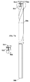
次に、本発明のいくつかの実施形態に関して、拡張可能な遠位部分103を備える骨材料除去デバイスを示す図1A〜図1Bを参照する。図1Aおよび図1Bの遠位部分103の拡大図が、各々の下に示されている。
Next, with respect to some embodiments of the present invention, reference is made to FIGS. 1A-1B showing an bone material removing device with an expandable
いくつかの実施形態では、デバイスは、遠位先端105と、シャフト107と、近位端109とを備える。
In some embodiments, the device comprises a
いくつかの実施形態では、デバイスの遠位部分103は、たとえば1つ、2つ、5つ、8つ、または任意のより大きい数もしくは中間の数の、切断歯111などの、複数の骨除去要素を備える。いくつかの実施形態では、切断歯111は、デバイスのシャフト107から拡張する。いくつかの実施形態では、さらに説明されるように、デバイスの回転によって起こされる遠心力が、切断歯を拡張するために、それらに作用する。
In some embodiments, the
いくつかの実施形態では、デバイスは、2つの動作構成に適合される。図1Aに示される第1の構成では、切断歯は閉鎖構成のままであり、たとえば、シャフトの円周内に含まれる。図1Bに示される第2のモードでは、切断歯は、開放構成へとシャフトから外部に拡張し、たとえば、シャフトの円周を越えて拡張する。いくつかの実施形態では、穿孔方向は、閉鎖構成に適合する。いくつかの実施形態では、穿孔方向は、歯がいったん開くと、歯が開いたままではなく閉鎖する構成に適合する。 In some embodiments, the device is adapted to two operating configurations. In the first configuration shown in FIG. 1A, the cutting teeth remain in the closed configuration and are contained, for example, within the circumference of the shaft. In the second mode shown in FIG. 1B, the cutting tooth extends outward from the shaft into an open configuration, eg, beyond the circumference of the shaft. In some embodiments, the perforation direction fits the closed configuration. In some embodiments, the perforation direction adapts to a configuration in which the teeth close rather than remain open once the teeth have opened.
いくつかの実施形態では、図1Aに示される第1の動作構成は、骨内で孔を穿孔するために使用される。任意選択で、穿孔は、デバイスの近位端109をドリルモータ(図示せず)に取り付けることによって実行される。いくつかの実施形態では、第1の構成は、場合によっては回転させずに、デバイスを既存の孔に通過させるために使用される。任意選択で、ばね要素(たとえば、歯111とシャフト107との間の)または結合材料(たとえば、要素上のコーティング)が、歯111をシャフト107の表面に適合するように維持する目的で小さい力を加えるために設けられる。
In some embodiments, the first motion configuration shown in FIG. 1A is used to perforate a hole in the bone. Optionally, drilling is performed by attaching the
いくつかの実施形態では、第1の動作構成では、切断歯111はシャフト内に含まれる。いくつかの実施形態では、切断歯は、シャフトの円周に位置決めされる。任意選択で、閉鎖構成では、切断歯は、シャフトの最大直径を越えて拡張しない。代替的に、閉鎖構成では、切断歯は、シャフトの直径を越えて拡張する。
In some embodiments, in the first motion configuration, the cutting
いくつかの実施形態では、図1Bに示される第2の動作構成は、骨内の孔の少なくとも一部分を広げるために使用される。いくつかの実施形態では、切断歯111は、シャフト107から外部に拡張し、たとえばシャフトの主軸に垂直に延びる。いくつかの実施形態では、切断歯111が開放構成へと拡張されたとき、切断歯111は、たとえば20%、70%、90%、およびより小さい数、より大きい数、または中間の数だけ、遠位部分103の少なくとも1つの断面たとえば遠位先端105の直径を増加させる。
In some embodiments, the second motion configuration shown in FIG. 1B is used to widen at least a portion of the hole in the bone. In some embodiments, the cutting
いくつかの実施形態では、使用者は、たとえばデバイスの回転の方向を選定することによって、動作構成を選択的に選定し得る。いくつかの実施形態では、一方向に、たとえば時計回りの方向に回転しているとき、切断歯111は、閉鎖構成においてシャフトに隣接したままである。追加および/または代替として、反時計回りの方向などの反対方向に回転しているとき、遠心力は、切断歯111を、シャフトの円周を越えて拡張させる。
In some embodiments, the user may selectively select the operating configuration, for example by selecting the direction of rotation of the device. In some embodiments, the cutting
いくつかの実施形態では、物体と接触するとき、回転は常に歯の拡張を引き起こすが、回転方向は、歯が開いたまたは閉じたままである傾向があるかどうかを決定する。 In some embodiments, rotation always causes tooth dilation when in contact with an object, but the direction of rotation determines whether the tooth tends to remain open or closed.
いくつかの実施形態は、さまざまな形状および/またはサイズの切断縁を有する切断歯111を備え、たとえば、切断縁は、方形の横断面、円形の横断面、または三角形の横断面を有する。いくつかの実施形態では、切断歯は、円弧として形作られる。任意選択で、円弧の長さは、シャフトの円周の半分である。一例では、2つの円弧形の切断歯は、シャフトの円周を完成させる。いくつかの実施形態では、円弧は、軸方向および/または半径方向に、厚さ、たとえば0.2mm、0.4mm、2mm、または任意のより薄い厚さ、中間の厚さ、もしくはより厚い厚さを有する。いくつかの実施形態では、切断歯111は、たとえば拡張する間に孔にやすりをかけるために、浸食外部とともに形成される。
Some embodiments include cutting
いくつかの実施形態では、切断歯111はシャフト107に接続され、たとえば、ヒンジまたはピボットを使用して接続される。いくつかの実施形態では、接続エリアは、切断歯111の自由な運動を阻止する外形を含み、たとえば、切断歯が一方向にのみ拡張して開くことを可能にする。いくつかの実施形態では、枢動の度合いは、必要に応じて製造され、たとえば枢動の軸に対して30度、60度、90度、または任意の中間の度数、もしくはより小さい度数で開くように切断歯を制限する。
In some embodiments, the cutting
いくつかの実施形態では、図1Bの遠位部分103の拡大版において凹部115の横に示されるなどの断面は、切断歯111が過度に拡張し、たとえば180度よりも大きい角度で開くのを防止する。
In some embodiments, a cross section, such as shown beside the
いくつかの実施形態では、シャフト107は、凹部115を備える。任意選択で、凹部115は、たとえばデバイスが閉鎖構成であるとき、切断歯111を受け入れる。
In some embodiments, the
いくつかの実施形態では、異なる歯は、異なる長さを有する。いくつかの実施形態では、異なる歯は、異なる軸方向位置を有する。たとえば、1つの切断歯は、シャフトの円周の半分に等しい長さに延び得、第2の切断歯は、シャフトの円周の4分の1である長さに延び得る。 In some embodiments, the different teeth have different lengths. In some embodiments, the different teeth have different axial positions. For example, one cutting tooth can extend to a length equal to half the circumference of the shaft, and a second cutting tooth can extend to a length that is a quarter of the circumference of the shaft.
いくつかの実施形態では、切断歯の形状ならびに/またはそれらの切断縁および/もしくは面のサイズは、孔を広げる特定のパターンを生じさせるように選択される。 In some embodiments, the shape of the cutting teeth and / or the size of their cutting edges and / or surfaces is selected to produce a particular pattern that widens the holes.
いくつかの実施形態では、切断歯は個々の様式で拡張し、たとえば、各切断歯は、別の歯とは無関係に拡張する。代替的に、切断歯は、拡張構成への1つの歯の開放が、たとえば隣接する歯を押すことによって、別の歯の開放をもたらすように製造され得る。 In some embodiments, the cut teeth expand in individual fashion, for example, each cut tooth expands independently of another tooth. Alternatively, the cut tooth can be manufactured such that the opening of one tooth to the dilated configuration results in the opening of another tooth, for example by pushing an adjacent tooth.
いくつかの実施形態では、切断歯は、たとえばそれらの歯を開くまたは閉鎖するために、ばね装荷であってよい。 In some embodiments, the cutting teeth may be spring loaded, for example to open or close those teeth.
いくつかの実施形態では、デバイスはドリルである。いくつかの実施形態では、デバイスはリーマーである。 In some embodiments, the device is a drill. In some embodiments, the device is a reamer.
いくつかの実施形態では、遠位先端はドリルビットである。任意選択で、遠位先端は、ねじ付き部分を備える。いくつかの実施形態では、近位端は、穿孔と係合するような形状にされ、たとえば、六角形を有する。 In some embodiments, the distal tip is a drill bit. Optionally, the distal tip comprises a threaded portion. In some embodiments, the proximal end is shaped to engage the perforation and has, for example, a hexagon.
いくつかの実施形態では、デバイスは、たとえばガイドワイヤ上で挿入されるために、カニューレ処置される。 In some embodiments, the device is cannulated to be inserted, for example, on a guide wire.
いくつかの実施形態では、デバイスは、マーキングを示す複数の深度を備える。 In some embodiments, the device comprises multiple depths indicating marking.
いくつかの実施形態では、デバイスは、Eagleステンレス鋼などのステンレス鋼から作製される。いくつかの実施形態では、切断歯111は、デバイスの残りと同じ材料から作製される、または異なる材料から作製される。
In some embodiments, the device is made from stainless steel, such as Eagle stainless steel. In some embodiments, the cutting
次に、本発明のいくつかの実施形態に関して、骨内に孔を穿孔し、その孔の少なくとも一部分を広げるための例示的な方法を示す図2A〜図2Dを参照する。それぞれ図2A〜図2Bおよび図2C〜図2Dに記載される段階中のデバイスの遠位先端の拡大図である図2E〜図2Fをさらに参照する。 Next, with respect to some embodiments of the present invention, reference is made to FIGS. 2A-2D showing exemplary methods for perforating a hole in the bone and widening at least a portion of the hole. Further refer to FIGS. 2E-2F, which are enlarged views of the distal tip of the device during the stage described in FIGS. 2A-2B and 2C-2D, respectively.
いくつかの実施形態では、デバイス201は、骨内に孔を穿孔するために使用される。いくつかの実施形態では、図2Aに示されるように、1つまたは複数の切断歯203は閉鎖構成である。いくつかの実施形態では、デバイスの遠位先端205は骨207に挿入される。いくつかの実施形態では、遠位先端205はドリルビットであり、任意選択で、ねじ付き部分を有する。いくつかの実施形態では、矢印217によって示される方向での骨への挿入中に、デバイス201は、たとえばドリルに接続されることによって、方向209などの方向に回転される。
In some embodiments,
いくつかの実施形態では、図2Bに示されるように、デバイスは、骨の両側間に延びる孔223(点線によってマークされる)を作製するために、骨207を通って穿孔する。いくつかの実施形態では、デバイス211の遠位部分は、骨207を越えて延びる。
In some embodiments, as shown in FIG. 2B, the device is perforated through
いくつかの実施形態では、骨207は、切断歯203が拡張するのを防止する。追加および/または代替として、骨207は、切断歯203を閉鎖構成に戻ることを強制する。
In some embodiments, the
いくつかの実施形態では、図2Cに示されるように、孔が穿孔されると、切断歯203は、シャフト215の外部に拡張するように強制される。いくつかの実施形態では、回転の方向を反対方向213に逆転させることによって、生じた遠心力は、切断歯203がヒンジ上で枢動することなどによってシャフトから外側に拡張するように、切断歯203に作用する。いくつかの実施形態では、この時点で、デバイスは、矢印219によって示される方向に、穿孔された孔内へと戻されるなど、後方に引っ張られる(たとえば、ドリルを使用して)。
In some embodiments, as shown in FIG. 2C, when the hole is drilled, the cutting
いくつかの実施形態では、図2Dに示されるように、回転の逆転された方向は、切断歯203を開放構成に保つ。いくつかの実施形態では、デバイスが既存の孔を通って後方に引っ張られると、切断歯213は、孔部分221で示されるように、孔の直径を広げる。いくつかの実施形態では、切断歯は、骨組織を切断および/または粉砕することによって、骨材料を除去する。いくつかの実施形態では、孔の初期直径は、10%、50%、90%、およびまたは中間の値、および/またはより大きい値だけ、広げられる。
In some embodiments, the reversed direction of rotation keeps the cutting
いくつかの実施形態では、切断歯203は、たとえば孔が狭い場合、孔の壁によって及ぼされる対向する力により開放構成のままである。
In some embodiments, the cutting
いくつかの実施形態では、孔の一部分のみが広げられる。任意選択で、孔の一部分の広げることは、たとえば、骨の狭いパートに引き寄せられ得るACLまたは/他の任意の靱帯もしくは物体を係留する場所を形成する。 In some embodiments, only part of the hole is widened. Optionally, widening a portion of the hole forms, for example, a place to anchor an ACL or / or any other ligament or object that can be attracted to a narrow part of the bone.
いくつかの実施形態では、回転の方向が、たとえば孔の途中で再度逆転され、切断歯203を、シャフトの内部で閉鎖構成に戻させる。いくつかの実施形態では、切断歯の面および/または縁は、孔との接触が半径方向の閉鎖力を切断歯に加えるように、湾曲している。
In some embodiments, the direction of rotation is reversed again, for example in the middle of the hole, causing the cutting
いくつかの実施形態では、次いで、デバイスが、任意選択で孔の残りの部分を広げずに、孔の残りの部分を通って引っ張り戻される。 In some embodiments, the device is then optionally pulled back through the rest of the hole without expanding the rest of the hole.
いくつかの実施形態では、たとえば、孔がすでに骨207内に存在する場合、デバイスは、たとえば閉鎖構成で孔を通して挿入され、回転時に既存の孔を広げるために既存の孔の少なくとも一部分に沿って切断歯が切断するように、開放構成で引っ張り戻されることによって、既存の孔を広げるためにのみ使用され得る。
In some embodiments, for example, if the hole is already in
図2Eの拡大図は、閉鎖構成での切断歯203を示す。任意選択で、デバイスは、第1の方向209に回転される。
The enlarged view of FIG. 2E shows the cutting
図2Fの拡大図は、開放構成での切断歯203を示す。任意選択で、デバイスは、第2の方向213に回転される。
The enlarged view of FIG. 2F shows the cutting
次に、本発明のいくつかの実施形態に関する、骨内に孔を穿孔し、その孔の少なくとも一部分を広げるための例示的な方法のフローチャートである図3を参照する。いくつかの実施形態では、デバイスが骨に挿入される301。いくつかの実施形態では、孔は、デバイスを使用して、たとえばデバイスの回転によって、骨を通って穿孔される303。代替的に、以前に言及されたように、デバイスは、骨内の既存の孔、たとえば、ドリルまたは他の任意の孔を形成するための手段を使用して以前に作成された孔を通過する。
Next, reference is made to FIG. 3 which is a flowchart of an exemplary method for perforating a hole in the bone and widening at least a part of the hole according to some embodiments of the present invention. In some embodiments, the device is inserted into the
いくつかの実施形態では、孔は、骨の一部分を通って穿孔され、たとえば、2mm、9mm、5cm、7cm、および/または任意のより浅い深度、中間の深度、もしくはより深い深度などの、骨内の特定の深度まで延びる。いくつかの実施形態では、穿孔された孔は、骨の2つの両面の間で延びる。 In some embodiments, the holes are perforated through a portion of the bone, eg, 2 mm, 9 mm, 5 cm, 7 cm, and / or any shallower, intermediate, or deeper depth of bone. Extends to a certain depth within. In some embodiments, the perforated hole extends between the two sides of the bone.
いくつかの実施形態では、デバイスの遠位部分は、孔の出口アパーチャを越えて延びる。いくつかの実施形態では、この位置決めは、切断歯が開放構成へと拡張することを可能にするために、十分に大きい内腔内に遠位部分を設置することを可能にする。任意選択で、十分に大きい内腔は、異なる場所、たとえば骨内に自然に形成された内腔に存在する。 In some embodiments, the distal portion of the device extends beyond the exit aperture of the hole. In some embodiments, this positioning allows the distal portion to be placed within a sufficiently large lumen to allow the cut tooth to expand into an open configuration. Optionally, a sufficiently large lumen resides in a different location, eg, a naturally formed lumen in the bone.
いくつかの実施形態では、切断歯の拡張は、デバイスの回転、たとえば孔の穿孔中に回転の方向とは反対方向の回転によって達成される305。任意選択で、回転中に生じる遠心力は、切断歯を開放構成へと押し出すのに十分なほど強い。
In some embodiments, dilation of the cutting tooth is achieved by rotation of the device, eg, rotation in the direction opposite to the direction of rotation during perforation of the
いくつかの実施形態では、切断歯が、延ばされた開放構成になると、デバイスは、孔を通して引っ張り戻され得る。いくつかの実施形態では、デバイスが引っ張り戻されるにつれて、切断歯が孔を広げる。任意選択で、回転速度は、歯の切断効果に影響を与える。 In some embodiments, the device can be pulled back through the hole when the cut tooth is in an extended open configuration. In some embodiments, the cutting tooth widens the hole as the device is pulled back. Optionally, the rotational speed affects the cutting effect of the teeth.
いくつかの実施形態では、デバイスは、孔の直径の少なくとも一部分を広げ307、たとえば、孔の長さの3分の1、孔の長さの半分、または孔の全長を広げる。いくつかの実施形態では、孔の直径は、10%、50%、90%、および/または中間の値、またはより大きい値だけ増加し得る。 In some embodiments, the device widens at least a portion of the hole diameter to 307, eg, one-third of the hole length, half the hole length, or the entire length of the hole. In some embodiments, the hole diameter can be increased by 10%, 50%, 90%, and / or intermediate or greater values.
いくつかの実施形態では、使用者は、たとえば孔を広げることを回避するために、切断歯を拡張しないことを選択的に決定する。任意選択で、デバイスは、閉鎖構成での歯を有する孔を通って引っ張り戻される。 In some embodiments, the user selectively decides not to dilate the cut tooth, for example to avoid dilating the hole. Optionally, the device is pulled back through a toothed hole in a closed configuration.
次に、本発明のいくつかの実施形態に関する、可撓性部分を有するシャフトを有する拡張可能な骨除去デバイスを示す図4を参照する。いくつかの実施形態では、シャフト401は、たとえば遠位先端405と近位端407との間に延びる可撓性部分403、またはその部分の区間を備える。
Next, refer to FIG. 4, which shows an expandable bone removal device having a shaft with a flexible portion for some embodiments of the present invention. In some embodiments, the
いくつかの実施形態では、可撓性部分403は、ばねを備える。任意選択で、ばねは、デバイスの回転中、トルクを遠位先端405に伝える。
In some embodiments, the
いくつかの実施形態では、遠位先端405は、切断歯などの拡張可能な部分を備える。いくつかの実施形態では、遠位先端405は、拡張可能な部分を備えない。任意選択で、遠位先端405はドリルビットである。
In some embodiments, the
いくつかの実施形態では、可撓性部分403は、デバイスの屈曲を可能にし、たとえば直接に接近できない骨場所における穿孔を可能にする。いくつかの実施形態では、たとえばデバイスが曲げられる場合、湾曲した孔が形成され得る。いくつかの実施形態では、デバイスは、ガイドワイヤ上で挿入される。
In some embodiments, the
いくつかの実施形態では、可撓性部分403は、シャフト401の残りと同じ直径を有する。いくつかの実施形態では、可撓性部分403は、シャフト401の直径よりも小さい直径を有する。
In some embodiments, the
いくつかの実施形態では、可撓性部分403を備えるばねは、ばねをシャフトに結合するのに適したレーザ溶接技法および/または他の技法を使用して、製造中にシャフト401に取り付けられる。
In some embodiments, the spring with the
次に、閉鎖構成における拡張可能な部分502を示す、拡張可能な遠位部分502を含む本発明の別の実施形態により構築された骨材料除去デバイス500を示す図5A〜図6Bを参照する。
Next, see FIGS. 5A-6B showing the bone
骨材料除去デバイス500が、遠位先端504と、長手方向シャフト506と、近位端508とを含むことがわかる。
It can be seen that the bone
骨材料除去デバイス500の遠位部分502は、好ましくは、単一の切断歯510を含む。遠位部分502が複数の切断歯510を含んでよいことは理解されよう。
The
図5A〜図5Bおよび図6A〜図6Bに見られるように、切断歯510が閉鎖構成と開放構成の両方でシャフト506の外周から拡張することは、本発明のいくつかの実施形態の特定の特徴である。
As seen in FIGS. 5A-5B and 6A-6B, the extension of the cutting
本発明の例示的な一実施形態では、以下で詳細に説明されるように、切断歯510と骨の一部分との間の遠心力および摩擦力は、拡張可能な部分502を開かせ、したがって、切断歯510は、長手方向シャフト506からさらに拡張する。
In one exemplary embodiment of the invention, the centrifugal and frictional forces between the cutting
デバイスは、2つの動作構成に適合される。 The device fits into two operating configurations.
第1の構成は図5A〜図5Bに示されており、切断歯510は、切断歯510の小さい部分のみが長手方向シャフト506の外周から拡張するように、閉鎖構成のままである。本発明の例示的な一実施形態では、切断歯510は、シャフト506の外周から約0.1mm拡張する。
The first configuration is shown in FIGS. 5A-5B, and the cutting
第2の構成は図6A〜図6Bに示されており、切断歯510は、骨材料除去デバイス500の開放構成を仮定して、より大きい程度、シャフト506の外周から外部に拡張する。
The second configuration is shown in FIGS. 6A-6B, where the cutting
図5A〜図5Bに示される第1の動作構成は、一般的には、骨内の孔を穿孔するために使用される。任意選択で、穿孔は、デバイス500の近位端508をドリル(図示せず)に取り付けることによって、実行される。いくつかの実施形態では、第1の構成は、場合によっては回転なしで、デバイス500を既存の孔に挿入するために使用される。
The first motion configuration shown in FIGS. 5A-5B is generally used to perforate a hole in the bone. Optionally, drilling is performed by attaching the
図5A〜図5Bに示される本発明の例示的な一実施形態によれば、第1の動作構成では、切断歯510は、シャフト506の外周からわずかに拡張する。
According to one exemplary embodiment of the invention shown in FIGS. 5A-5B, in the first motion configuration, the cutting
図6A〜図6Bに示される本発明の例示的な一実施形態によれば、第2の動作構成は、骨内の孔の少なくとも一部分を広げるために使用される。いくつかの実施形態では、切断歯510は、シャフト506の外周から外部に拡張する、たとえば、図5A〜図5Bに示される第1の動作構成におけるよりも大きい程度、シャフトの主軸に垂直に拡張する。いくつかの実施形態では、切断歯510が開放構成に拡張されるとき、切断歯510は、たとえば20%、70%、90%、ならびに/または任意のより小さい数字、より大きい数字、もしくは中間の数字だけ、遠位部分502の少なくとも1つの断面、たとえば遠位先端504の直径を増加させる。
According to one exemplary embodiment of the invention shown in FIGS. 6A-6B, the second motion configuration is used to widen at least a portion of the hole in the bone. In some embodiments, the cutting
使用者は、たとえば骨材料除去デバイス500の回転の方向を選定することによって、動作構成を選択的に選定し得る。いくつかの実施形態では、一方向に、たとえば時計回りの方向に回転しているとき、切断歯510は、シャフト506に隣接するままであり、閉鎖構成で、それからわずかに拡張する。追加および/または代替として、反時計回りの方向などの反対方向に回転しているとき、骨部分とシャフト506の円周を越えて拡張する切断歯510の部分との間で形成される摩擦力および遠心力によって、切断歯510は、シャフト506の円周を越えてより大きい程度に拡張する。
The user can selectively select the operation configuration by, for example, selecting the direction of rotation of the bone
次に、近位端508と遠位先端504とその中における切断歯510の挿入のための凹部512とを有する長手方向シャフト506からなる、本発明の例示的な一実施形態に従って構築された骨材料除去デバイス500のドリルを示す図7A〜図7Bを参照する。いくつかの実施形態では、遠位先端504はドリルビットであり、任意選択で、ねじ付き部分を有する。
Next, a bone constructed according to an exemplary embodiment of the invention, comprising a
図7A〜図7Bでは、ドリルは、カニューレ処置され、残留穿孔材料の洗浄または除去のために、遠位端508から近位先端504まで延びる長手方向の孔514を含むことがわかる。
In FIGS. 7A-7B, it can be seen that the drill is cannulated and includes a
次に、骨材料除去デバイス500のドリルの凹部512に挿入可能な切断歯510の例示的な設計を示す図8A〜図8Dを参照する。
Next, reference is made to FIGS. 8A-8D showing an exemplary design of the cutting
次に、閉鎖構成、部分的開放構成、および拡張された開放構成における骨材料除去デバイス500をそれぞれ示す図9A〜図9Cを参照する。
Next, reference is made to FIGS. 9A-9C showing the bone
図9Aでは、切断歯510が閉鎖構成であるとき、切断歯510はシャフト506の外周をわずかに越えて拡張することがわかる。
In FIG. 9A, it can be seen that when the cutting
図9Bでは、切断歯が部分的に開くと、切断歯510は、シャフト506の外周をさらに越えて拡張することがわかる。
In FIG. 9B, it can be seen that when the cutting teeth are partially opened, the cutting
図9Cでは、切断歯510が開放構成であるとき、切断歯510がシャフト506の外周を最大限に越えて拡張することがさらにわかる。
In FIG. 9C, it is further seen that when the cutting
第1の直径の孔が骨部分を通って穿孔されたとき骨部分内に示される、閉鎖構成での骨材料除去デバイスを示す図10A〜図10Cをさらに参照する。 Further refer to FIGS. 10A-10C showing the bone material removal device in a closed configuration, which is shown within the bone portion when a hole of first diameter is perforated through the bone portion.
図10A〜図10Cでは、骨材料除去デバイス500のドリルが、閉鎖構成において、遠位先端504を骨部分に挿入し、たとえばドリルへの接続によって、デバイス500を回転させ、拡張部分502が骨部分から延び、切断歯510が骨部分の遠位方向に位置決めされるかまたは骨部分に当接するかのどちらかまで、骨部分全体を通って穿孔することによって、骨部分内に第1の直径の孔516を設けるために使用されることがわかる。
In FIGS. 10A-10C, the drill of the bone
ドリルは、切断歯510がシャフト506の円周をわずかに越えて拡張するように、好ましくは時計回りの方向に回転され、切断歯510を閉鎖構成に保つ。
The drill is preferably rotated clockwise so that the cutting
次に、第1の直径の孔が骨部分を通って穿孔されたとき骨部分内に部分的に示される、拡張構成での骨材料除去デバイス500を示す図11A〜図11Cを参照する。
Next, see FIGS. 11A-11C showing the bone
図11A〜図11Cでは、骨材料除去デバイス500のドリルが、拡張構成において、ドリルの回転方向を逆転させ、広げられた孔部分を提供するように、第1の直径の孔の一部分を通って反対の軸方向に穿孔することによって、好ましくは第1の直径よりも大きい第2の直径の孔518を設けるために使用されることがわかる。
In FIGS. 11A-11C, the drill of the bone
切断歯510と骨部分との間に生じる摩擦力と、ドリルの回転の方向を逆転させることによって引き起こされる遠心力は、切断歯510が拡張し、開放構成を仮定することを可能にすることが理解されよう。
The frictional force generated between the cutting
次に、第2の直径の孔が骨部分を通って部分的に穿孔されたとき骨部分内に示される、拡張構成での骨材料除去デバイス500を示す図12A〜図12Bを参照する。
Next, see FIGS. 12A-12B showing the bone
ドリルの回転方向の逆転に続いて、ドリルが、第1の直径の穿孔された孔516の中へと近位方向に引っ張り戻され、切断歯510の拡張構成により、第2の直径の孔518が、以前に形成された第1の直径の孔516に沿って、骨部分を通って部分的に形成される。
Following the reversal of the direction of rotation of the drill, the drill is pulled back proximally into the
次に、第1の直径の盲孔は骨部分を通って部分的に穿孔され、骨材料除去デバイスは閉鎖構成で示される、デバイスの使用のさらなる方法を示す、骨部分内に示される骨材料除去デバイス500を示す図13A〜図13Bを参照する。
A blind hole of first diameter is then partially perforated through the bone portion and the bone material removing device is shown in a closed configuration, indicating a further method of use of the device, the bone material shown within the bone portion. See FIGS. 13A-13B showing the
図13A〜図13Bでは、骨材料除去デバイス500の遠位先端504が骨部分内で位置決めされ、骨部分を越えて延びず、したがって、切断歯510も骨部分内に存在しているように、骨材料除去デバイス500のドリルが、閉鎖構成において、遠位先端504を骨部分に挿入し、たとえばドリルへの接続によって、デバイス500を回転させ、好ましくは第1の直径の盲孔520を穿孔することによって骨部分内に第1の直径の孔516を設けるために使用されることがわかる。
In FIGS. 13A-13B, the
ドリルは、切断歯510がシャフト506の円周をわずかに越えて拡張するように、好ましくは時計回りの方向に回転され、切断歯510を閉鎖構成に保つ。
The drill is preferably rotated clockwise so that the cutting
次に、第2の直径の盲孔は骨部分を通って部分的に穿孔され、骨材料除去デバイス500は拡張構成で示される、デバイスの使用のさらなる方法を示す、骨部分内の骨材料除去デバイス500を示す図14A〜図14Bを参照する。
A second diameter blind hole is then partially perforated through the bone portion and the bone
図14A〜図14Bでは、骨材料除去デバイス500のドリルが、開放構成において、ドリルの回転方向を逆転させ、好ましくは骨部分内にアンダーカット524を形成する広げられた孔部分を提供するために第1の直径の孔の一部分を通って反対の軸方向に穿孔することによって、好ましくは第1の直径よりも大きい第2の直径の盲孔522を設けるために使用されることがわかる。
In FIGS. 14A-14B, in order for the drill of the bone
その拡張が0.1〜0.5mmの範囲内であり得る、シャフト506の円周をわずかに越えて拡張する切断歯510は、閉鎖構成において、回転の方向が逆転されると、骨の一部分に対して摩擦力を生じさせることが、本発明のいくつかの実施形態の特定の特徴である。その結果生じる摩擦力は、切断歯510の拡張を引き起こし、開放構成を仮定しながら、第2の直径の孔522を穿孔することを可能にする。
The cutting
ドリルの回転方向の逆転に続いて、ドリルが、第1の直径の穿孔された孔520の中へと近位方向に引っ張り戻され、切断歯510の拡張構成により、第2の直径の孔522が、以前に形成された第1の直径の孔520に沿って、骨部分を通って部分的に形成される。
Following the reversal of the direction of rotation of the drill, the drill is pulled back proximally into the
第1の直径の孔520および第2の直径の孔522からなる行き止まりの(blind)アンダーカットが、単一の骨材料除去デバイス500を骨から除去することなく、デバイス500によって形成されることが、本発明のいくつかの実施形態の特定の特徴である。
A blind undercut consisting of a
説明された行き止まりのアンダーカットが骨内でのアンカーの位置決めのために使用され得ることが理解されよう。 It will be appreciated that the described dead end undercut can be used for anchor positioning within the bone.
本発明の例示的な一実施形態では、遠位の拡張可能な部分502は、ドリルの長手方向シャフト506とともに一体的に形成され得る。
In one exemplary embodiment of the invention, the distal
本発明の別の実施形態によれば、遠位の拡張可能な部分502は、好ましくはねじ切り可能な(threadable)接続を使用して、ドリルの長手方向シャフト506に取り付け可能である。この実施形態によれば、ドリルは、第1の直径の孔520および第2の直径の孔522からなる可変の直径の孔を形成するために、上記で説明されたように使用され得、次いで、ドリルの長手方向シャフト506は、拡張可能な遠位部分502からねじ切り可能に取り外され得、拡張可能な遠位部分502は、好ましくは、形成された行き止まりのアンダーカット内に固定的に位置決めされ、アンカーとして使用される。
According to another embodiment of the invention, the distal
第2の直径の孔522が形成された後、切断歯510は、開放された拡張構成で位置決めされるので、遠位の拡張可能な部分502は、骨部分内に確実に位置決めされ、近位方向に除去されることはできず、したがって、安全なアンカーを提供する。
After the
本発明の別の実施形態によれば、遠位部分502の長さは骨材料除去デバイス500の直径よりも大きく、遠位の拡張可能な部分502は、ねじ切り不可能な接続によってドリルの長手方向シャフト506に取り付け可能である。いくつかの実施形態によれば、ドリルは、第1の直径の孔520および第2の直径の孔522からなる可変の直径の孔を形成するために、上記で説明されたように使用され得、次いで、ドリルの長手方向シャフト506は、拡張可能な遠位部分502から取り外され得る。次いで、遠位部分は、行き止まりのアンダーカット内の方位を変更して、その初期の長手方向の方位に対して約90度を回転させる。拡張可能な遠位部分502の長さは第1の直径520よりも大きいので、遠位の拡張可能な部分502は、骨部分内に確実に位置決めされ、近位方向に除去されることはできず、したがって、安全なアンカーを提供する。
According to another embodiment of the invention, the length of the
遠位部分がドリルの長手方向シャフト506から取り外し可能である例示的な一実施形態によれば、遠位部分は、チタンまたは他の任意の生物学的に適切な材料から形成されることが理解されよう。
According to an exemplary embodiment in which the distal portion is removable from the
次に、本発明のさらに別の実施形態により構築された、図5A〜図5Bに示される骨除去デバイスに類似した骨除去デバイスのドリル600の2つの正面図を示す図15A〜図15Bを参照する。
Next, see FIGS. 15A-15B showing two front views of a bone
ドリル600は、近位端608と遠位先端610とその中における切断歯の挿入のための凹部612とを有する長手方向シャフト606を含む。いくつかの実施形態では、遠位先端610はドリルビットであり、任意選択で、ねじ付き部分を有する。
The
ドリルは、カニューレ処置され、残留穿孔材料の洗浄または除去のために遠位先端610から近位端608に延びる長手方向の孔を含むことに留意されたい。
Note that the drill is cannulated and contains a longitudinal hole extending from the
次に、骨材料除去デバイスのドリル600の凹部612に挿入可能なカバー614を示す、図16A〜図16Cを参照する。
Next, see FIGS. 16A-16C showing a
カバー614は、その外側の寸法が好ましくは骨除去材料のドリル600の円周に対応するような形状にされる。カバー614は、近位端616と遠位端618とを有する。特に図16A〜図16Bでは、さらに詳細に図示および説明されるように、凹部620が、中へのヒンジピンの挿入のために、カバー614の遠位端618内に形成されることがわかる。長手方向に延びる孔622が、凹部620内に形成される。
The
次に、骨材料除去デバイスのドリル600の凹部612に挿入可能な切断歯630の例示的な設計を示す図17A〜図17Dを参照する。
Next, reference is made to FIGS. 17A-17D showing an exemplary design of the cutting
切断歯630は、近位端632と遠位端634と支持部材636とを有し、支持部材636は、近位端632から近位方向に延びる略円筒状の近位部分638と、遠位端634から遠位方向に延びる略円筒状の遠位部分640とを有する。長手方向の孔642は、支持部材636の長さ全体を通って延びる。
The cutting
次に、ヒンジピン650を使用して組み付けられた骨除去デバイスのドリル600とカバー614とを示す、骨除去デバイスの部分的アセンブリを示す、図18A〜図18Cを参照する。図18Cの断面図では、特に、カバー614がドリル600の凹部612に挿入され、ヒンジピン650が、カバー614の孔622に挿入された近位端652と、ドリル600内に形成された孔に挿入された遠位端654とを有することがわかる。
Next, see FIGS. 18A-18C showing the partial assembly of the bone removal device, showing the
ヒンジピン650の長さは、ヒンジピン650の近位端652と遠位端654の両方が実質的にドリル600へと延び、その中にしっかりと保持されるようなものであることが理解されよう。
It will be appreciated that the length of the
次に、閉鎖構成での骨材料除去デバイスを示す、図19A〜図19Cを参照する。 Next, see FIGS. 19A-19C showing the bone material removal device in a closed configuration.
図19Cでは、特に、切断歯630が、ヒンジピン650を使用して骨除去デバイスのドリル600の凹部612に挿入されることがわかる。切断歯630の近位端632がカバー614の遠位端618と係合し、切断歯630の支持部材636の遠位部分638がカバー614の凹部620および長手方向の孔622に挿入されることがわかる。切断歯630の支持部材636の遠位部分640は、ドリル600の長手方向の孔に挿入される。
In FIG. 19C, in particular, it can be seen that the cutting
ヒンジピン650を使用したドリル600および切断歯630の前述のアセンブリは、ドリル600と切断歯630との間のしっかりとした枢動可能な接続を可能にすることが、本発明のいくつかの実施形態の特定の特徴である。カバー614内に形成された凹部620へのヒンジピン650の挿入と、ドリル600内のその端の両方にヒンジピン650がしっかりと保持されるということにより、切断歯630が、ドリル600の凹部612内に確実に保持され、それから除去されることはできない。
It is in some embodiments of the invention that the aforementioned assembly of the
ヒンジピン650が破壊された場合ですら、切断歯630が、一方の端でドリル600に、他方の端でカバー614に非可逆的に挿入される支持部材636により、ドリル600に取り付けられで確実に保持されることが、本発明のいくつかの実施形態の特定の特徴である。
Even if the
したがって、切断歯630は、ヒンジピン650または支持部材636のうちの少なくとも1つによってドリル600に非可動的に取り付けられることに留意されたい。
Therefore, it should be noted that the cutting
ヒンジピン650の長さを増加させることは、ヒンジピン650の破損を生じさせることなく、ドリルに及ぼされ得る力を、対応して増加させることが理解されよう。
It will be appreciated that increasing the length of the
図19A〜図19Cでは、切断歯630が閉鎖構成であるとき、切断歯630がシャフト606の外周をわずかに越えて拡張することがわかる。
In FIGS. 19A-19C, it can be seen that when the cutting
次に、拡張構成での骨材料除去デバイスを示す図20A〜図20Cを参照する。 Next, reference is made to FIGS. 20A to 20C showing the bone material removing device in the extended configuration.
切断歯630は、ヒンジピン650のまわりで枢動可能である。開放拡張構成では、切断歯630がシャフト606の外周を最大限に越えて拡張することがわかる。
The cutting
図15A〜図20Cに示される骨材料除去デバイスの動作は、図10A〜図14Bに示された骨材料デバイス500の動作に類似している。
The operation of the bone material removing device shown in FIGS. 15A to 20C is similar to the operation of the
次に、本発明のいくつかの実施形態に関する、延長可能な切断歯2106を備える例示的な骨材料除去デバイス2100を示す図21を参照する。
Next, reference is made to FIG. 21 showing an exemplary bone
いくつかの実施形態では、デバイス2100はシャフト2102を備える。任意選択で、ヘッド2108は、シャフトの遠位端で構成される。
In some embodiments, the
いくつかの実施形態では、切断歯2106は、たとえば歯が閉鎖構成であるとき、シャフト2102内に形成された凹部2110内で少なくとも部分的に受け入れられる。
In some embodiments, the cutting
いくつかの実施形態では、切断歯2106は、たとえばヒンジによって、シャフト2102に枢動可能に接続される。
In some embodiments, the cutting
いくつかの実施形態では、ヒンジ(この図では隠されている)が、シャフトの中心の長手方向軸2120に沿って位置決めされる。代替的に、ヒンジは、軸2120からずらされて位置決めされ、たとえば、軸2120から、たとえば、0.7mm、1.3mm、1.8mm、または中間の距離、より長い距離、またはより短い距離などの、0.5〜2mmに及ぶ範囲の距離のところに位置決めされる。
In some embodiments, the hinge (hidden in this figure) is positioned along the
いくつかの実施形態では、たとえば本明細書に示されるように、切断歯2106は切断面2112を備える。いくつかの実施形態では、切断表面の少なくとも一部分に湾曲とともに形成された切断面2112、たとえば、部分2114などの表面の少なくとも一部分は、凹状である。追加または代替として、部分2116などの表面の少なくとも一部分は、平坦である。
In some embodiments, the cutting
いくつかの実施形態では、平面状部分2116は近接軸2120内に構成され、湾曲した部分2114は、平面状部分2116に半径方向外側に構成される。いくつかの実施形態では、歯の閉鎖中などに、平面状部分2116は、シャフト2102内の凹部2110の内側壁に押しつけられる。任意選択で、平面状部分2116は、歯の過度の閉鎖(たとえば、力が歯の背壁2122に加えられるとき、歯が凹部2110内により深く入る)に抵抗する。平面状部分2116の潜在的な利点としては、たとえば、歯の縁または隅での閉鎖と比較して、歯がシャフト材料に対して凹部2110に押し込まれているときの、増加された耐摩耗性および/または減少された破損のリスクがあり得る。
In some embodiments, the
いくつかの実施形態では、ヘッド2108に向かって遠位方向に面する歯2106の上部表面2118は、平坦である。任意選択で、上部表面2118は、歯が閉位置にあるとき、ヘッド2108の底部表面と係合するように構成され、たとえば、底部表面との間に間隙が形成されないように、ヘッド2108の底部表面と接触するのに適した平坦な表面として形成される。
In some embodiments, the
いくつかの実施形態では、開放構成では、歯2106の半径方向に外側の縁2124は、たとえば、シャフトの半径2130たとえば凹部2110の真下に構成されたシャフト部分の半径の1.1〜1.5倍の範囲で、シャフトの軸2120から距離2126のところに設置される。任意選択で、距離2126は、たとえば外科医によって、所望の直径の孔を生じさせるように選択される。場合によっては、移植片が回収され、開いた歯の程度は、この移植片を受け入れるのに適した直径まで孔を広げるなどのように選択される。
In some embodiments, in an open configuration, the radial
いくつかの実施形態では、シャフト2102は、たとえば本明細書で示されるように、円筒状である。任意選択で、骨に挿入されると、シャフト2102は、類似の外形を有する孔を生じさせる、略円筒状の回転のボリュームを画定する。代替的に、シャフト2102は異なる外形を備え、たとえば、六角形または八角形の断面などの多角形の断面を備える。任意選択で、多角形の断面を有するシャフトによって画定された回転のボリュームも、円筒状である。
In some embodiments, the
いくつかの実施形態では、デバイス2100は、ねじれ型(twist−type)ドリルビットなどのドリルビットである。いくつかの実施形態では、デバイスのシャフト2102は、1つまたは複数の縦溝2104とともに形成される。任意選択で、縦溝2104のねじれ具合は、特定の骨片除去具合をもたらすように選択される。
In some embodiments, the
いくつかの実施形態では、ヘッド2108は、任意選択で尖った先端2126とともに形成された、テーパのついた遠位端を備える。
In some embodiments, the
いくつかの実施形態では、歯2106は、たとえば、4〜7mm、3〜9mm、2〜5mm、または中間の範囲、より大きい範囲、またはより小さい範囲に及ぶ、先端2124から距離2128などの、先端2126からある距離に、近位方向に設置される。任意選択で、距離2128は、一方では、骨を越えて構成された組織の損傷を減少させるなどのために、遠位先端2126に十分に近くなるように、他方では、先端の穿孔機能に干渉しないおよび/または遠位部分の強度に影響を与えないように、遠位先端2126から十分に離隔されるように、選択される。
In some embodiments, the
いくつかの実施形態では、シャフト2102の近位端(この図には示されていない)は、たとえばシャンクとともに形成された、ドリルと係合するように構成される。 In some embodiments, the proximal end of shaft 2102 (not shown in this figure) is configured to engage a drill, for example formed with a shank.
骨材料除去デバイスのさまざまな実施形態は、さまざまな数の切断歯、たとえば2つ、3つ、4つ、5つ、8つ、10、または中間の数、より大きい数、またはより小さい数の切断歯を含み得る。任意選択で、複数の切断歯は、シャフトのまわりに周方向に分散される。任意選択で、複数の切断歯は、長手方向軸2120に沿ってさまざまな場所に位置決めされる。
Different embodiments of the bone material removal device include a different number of cutting teeth, eg, two, three, four, five, eight, ten, or an intermediate number, a larger number, or a smaller number. May include amputated teeth. Optionally, the plurality of cutting teeth are circumferentially dispersed around the shaft. Optionally, the plurality of cutting teeth are positioned at various locations along the
次に、本発明のいくつかの実施形態に関して、切断歯の閉鎖構成(A)と切断歯の開放構成(B)とを示す、骨除去のための切断歯を備えるデバイスの正面図である図22A〜図22Bを参照する。 Next, it is a front view of the device provided with the cutting tooth for bone removal which shows the closed structure (A) of the cutting tooth and the open structure (B) of the cutting tooth with respect to some embodiments of this invention. 22A to 22B.
閉鎖構成での歯2106を示す図22Aを参照すると、いくつかの実施形態では、歯2106の少なくとも一部分2200が、シャフトを越えて延び、たとえば、シャフトの周囲から距離2202まで延び、このシャフトは、たとえば、0.2mm、0.3mm、または中間の距離、より長い距離、またはより短い距離などの、0.1〜0.4mmの範囲に及ぶ。任意選択で、歯2106の突き出た部分2200は、デバイスによって穿孔される孔の直径を増加させ、たとえば、歯の突き出た部分2200のないシャフトによって形成されたであろう直径と比較して、0.5%、2%、5%、10%、または中間のパーセンテージ、より大きいパーセンテージ、またはより小さいパーセンテージだけ、孔の直径を増加させる。たとえば、シャフトの直径が、たとえば、4.5mmの場合、切断歯の突き出た部分を有するデバイスによって形成される孔の直径(歯が閉鎖構成であるとき)は、たとえば、4.6〜5mmの範囲に及び得る。
With reference to FIG. 22A showing the
いくつかの実施形態では、ヒンジ2204(この図はデバイス2204の正面図を示すので、ヒンジの場所を示す)は、シャフトの周囲から遠ざかるように位置決めされ、たとえば、0.2mm、0.3mm、0.35mm、または中間の距離、より大きい距離、またはより小さい距離などの、0.15〜0.4mmの範囲に及ぶ距離2206のところに位置決めされる。シャフトの周囲から遠ざかるように設置されたヒンジの潜在的な利点としては、ヒンジの破損などの損傷のリスクを減少させることがあり得る。 In some embodiments, the hinge 2204 (which shows the location of the hinge as this figure shows a front view of the device 2204) is positioned away from the perimeter of the shaft, eg, 0.2 mm, 0.3 mm, etc. Positioned at a distance of 2206 ranging from 0.15 to 0.4 mm, such as 0.35 mm, or an intermediate distance, a larger distance, or a smaller distance. A potential advantage of hinges installed away from the perimeter of the shaft may be to reduce the risk of damage such as hinge breakage.
いくつかの実施形態では、突き出た部分2200の半径方向外側の縁2124は、ヒンジ2204によって画定された軸と平行に延びる(近位−遠位方向に延びる)。代替的に、縁2124は傾斜しており、ヒンジ2204によって画定された軸に対して、ある角度で構成される。
In some embodiments, the radial
図22Bは、本発明のいくつかの実施形態による、開放構成での歯2106を示す。いくつかの実施形態では、たとえば凹状表面とともに形成された、湾曲した部分2114の湾曲2208の半径は、たとえば、1.5mm〜4mmの範囲に及ぶ。
FIG. 22B shows
いくつかの実施形態では、歯2106は、たとえば、除去された骨材料のためのさらなる除去トラックを提供するために、切断面2112の凹所が縦溝2104とは反対の方向に面するように、シャフト2102に対して位置決めされる。任意選択で、凹所と縦溝は、直径に沿って対向する。
In some embodiments, the
いくつかの実施形態では、歯2106は、ニチノール、ステンレス鋼、プラチナ、他の金属、PEEKなどのポリマー、および/または他の硬質材料などの硬質材料から形成される。任意選択で、歯は、骨と係合したとき破壊および/または変形しないように、骨組織よりも剛性の材料から形成される。
In some embodiments, the
いくつかの実施形態では、デバイスが、たとえば、5rpm、70rpm、250rpm、700rpm、または中間の速度、より高い速度、またはより低い速度などの、0.01〜1000rpmの範囲に及ぶ速度で回転される。いくつかの実施形態では、デバイスは、手動で操作される。追加または代替として、デバイスは、たとえばシャフトの近位端で、外科用ドリルなどのドリルに結合される。 In some embodiments, the device is rotated at speeds ranging from 0.01 to 1000 rpm, such as, for example, 5 rpm, 70 rpm, 250 rpm, 700 rpm, or intermediate speeds, higher speeds, or lower speeds. .. In some embodiments, the device is manually manipulated. As an addition or alternative, the device is coupled to a drill, such as a surgical drill, for example at the proximal end of the shaft.
いくつかの実施形態では、歯の剛性は、回転速度に従って選択され、たとえば、歯は、より高い回転速度に耐え、歯の欠けなどの損傷を減少させるために、より弾性であるように選択される。それぞれ、より剛性の歯が、より低い回転速度とともに使用可能である。 In some embodiments, the stiffness of the tooth is selected according to the speed of rotation, for example, the tooth is selected to be more elastic in order to withstand higher speeds of rotation and reduce damage such as chipping of the tooth. Tooth. Each, stiffer teeth can be used with lower rotational speeds.
いくつかの実施形態では、歯の剛性は、孔が穿孔される組織に従って選択される。一例では、脛骨体部分内で穿孔するために、チタンから形成された歯が使用され得る。任意選択で、1000rpmの回転速度が適用される。別の例では、脛骨プラトー内などの、脛骨の遠位端および/または近位端内で穿孔するために、選択される歯は、チタンよりも硬いステンレス鋼(PH174)から形成され得てよく、回転速度は、より遅くてよく、たとえば500rpmであってよい。 In some embodiments, the stiffness of the tooth is selected according to the tissue in which the hole is perforated. In one example, teeth formed from titanium may be used to perforate within the tibial body. Optionally, a rotation speed of 1000 rpm is applied. In another example, the tooth selected for perforation within the distal and / or proximal end of the tibia, such as within the tibial plateau, may be formed from stainless steel (PH174), which is harder than titanium. The rotation speed may be slower, for example 500 rpm.
次に、本発明のいくつかの実施形態に関する、孔を穿孔し、その孔の少なくとも一部分を広げるための方法のフローチャートである図23を参照する。 Next, refer to FIG. 23, which is a flowchart of a method for perforating a hole and expanding at least a part of the hole according to some embodiments of the present invention.
いくつかの実施形態では、骨材料除去デバイスが、穿孔などによって、骨に挿入される2300。いくつかの実施形態では、挿入することは、孔を形成するためにデバイスを回転させること2302を備える。いくつかの実施形態では、デバイスの切断歯は、デバイスのシャフトの周囲を越えて拡張し、閉位置における切断歯の半径方向の程度によって画定された直径を有する孔を形成する。
In some embodiments, the bone material removing device is inserted into the bone, such as by perforation, 2300. In some embodiments, the insertion comprises rotating the device to form a
いくつかの実施形態では、デバイスは、入った側の面とは異なる骨の面を出るまで、骨に挿入される。任意選択で、デバイスは、少なくとも切断歯が孔の遠位開口を出るまで、前進される。代替的に、デバイスは、デバイスの長さに沿った他の部分が孔の遠位開口を出るまで、前進される。 In some embodiments, the device is inserted into the bone until it exits a surface of the bone that is different from the surface on which it entered. Optionally, the device is advanced at least until the cut tooth exits the distal opening of the hole. Alternatively, the device is advanced until another portion along the length of the device exits the distal opening of the hole.
代替的に、いくつかの実施形態では、デバイスは、骨内で特定の距離のみ前進され、孔に対する遠位開口を形成しない。 Alternatively, in some embodiments, the device is advanced only a certain distance within the bone and does not form a distal opening to the hole.
いくつかの実施形態では、たとえば、必要な深度の孔が得られたら、デバイスは、デバイス2304の挿入のために使用された回転方向とは反対の方向に回転される。いくつかの実施形態では、たとえば、切断歯が孔の中にある場合、歯の突き出た部分は、孔の壁に押しつけられる。任意選択で、回転が継続するにつれて、孔の壁によって歯の突き出た部分に加えられる抵抗力は、歯が開放構成へと回転するように強制されるまで増加する。追加または代替として、穿孔方向とは反対の方向におけるデバイスの回転は、たとえば遠心力により、歯の開放をもたらす。いくつかの実施形態では、回転に基づく開放は、歯が前進されて骨を通過し、孔の壁によって課される抵抗などと比較して歯の開放に対してより少ない抵抗を課す内腔内に位置決めされたとき、実行される。
In some embodiments, for example, once a hole of the required depth is obtained, the device is rotated in a direction opposite to the direction of rotation used to insert the
いくつかの実施形態では、開放された歯を備えるデバイスは、形成された孔の少なくとも一部分を広げるために、近位方向に引っ張り戻される2306。任意選択で、デバイスは、歯を開位置に保つために、初期穿孔方向に対向する方向に回転される2308。いくつかの実施形態では、開放された歯は、孔の初期壁を取り囲む骨組織を切断し、それによって、孔の直径を増加させる。
In some embodiments, the device with open teeth is pulled back proximally to widen at least a portion of the formed
いくつかの実施形態では、孔の一部分のみが広げられる。任意選択で、デバイスは、歯を閉鎖させるために、第1の初期穿孔回転においてもう一度回転される。任意選択で、歯が閉鎖されると、デバイスは、孔の近位開口を通してなどの、孔から除去される。代替的に、デバイスは、その長さに沿って孔を広げるために、開放構成での歯を有する孔の全長に沿って引っ張られる。 In some embodiments, only part of the hole is widened. Optionally, the device is rotated again in the first initial perforation rotation to close the teeth. Optionally, when the tooth is closed, the device is removed from the hole, such as through a proximal opening in the hole. Alternatively, the device is pulled along the overall length of the toothed hole in the open configuration to widen the hole along its length.
次に、本発明のいくつかの実施形態に関する、切断歯2106におけるシャフト2102の横断面図である図24A〜図24Bを参照する。
Next, reference is made to FIGS. 24A to 24B, which are cross-sectional views of the
いくつかの実施形態では、たとえば図24Aに示されるように、切断面2112は、歯が閉位置にあるとき、シャフト壁2406に寄りかかっている。任意選択で、切断面の平坦部分2116は、シャフト壁2406と十分に接触したが、凹状部分2114は、シャフト壁2406と切断面との間に間隙2402を画定する。いくつかの実施形態では、ギャップ2402は、たとえば、0.3mm、0.45mm、0.6mm、または中間の距離、より大きい距離、またはより小さい距離などの、0.25〜0.7mmの範囲に及ぶ。
In some embodiments, the
いくつかの実施形態では、たとえば、デバイスが、歯を開くために穿孔方向とは反対の方向に回転されるとき、形成された孔2406の壁によって適用された力2404は、突き出た部分2200に作用する。任意選択で、摩擦が、切断歯2106の縁2124と孔壁との間に生じさせられる2406。場合によっては、力2404は、歯2106にスピンさせて開放させるまで、回転が継続するにつれて増加する。
In some embodiments, for example, when the device is rotated in the direction opposite to the drilling direction to open the teeth, the
いくつかの実施形態では、たとえば図24Bに示されるように、さまざまな力が、孔を広げる間に、開いた歯2106に作用し得る。場合によっては、力2408が、歯が切断する骨組織の抵抗により、切断面2112上に加えられる。任意選択で、切断面2112の湾曲は、切断面2112に沿って力2408を分散させるように構成される。任意選択で、凹状部分2114の円弧状構成は、力2408を、たとえば平坦な表面と比較して、より広い表面積にわたって拡散させ、切断面2112に沿った各点に作用する力の大きさを減少させる。
In some embodiments, various forces can act on the
いくつかの実施形態では、力2410は、シャフト壁2406によって、背壁2122上に加えられる。任意選択で、力2410は、歯2106の移動を制限し、たとえば、歯2106が過度に開くのを防止する。
In some embodiments, the
いくつかの実施形態では、歯2106は、歯2106がヒンジ上で自由に回転することを可能にするように、ヒンジ2204に結合される。いくつかの実施形態では、歯2106は、ヒンジ2204のロッドにねじ込まれることになる凹部2412を備える。任意選択で、凹部2412は、ロッドヒンジ上で自由に回転するような形状および/またはサイズにされる。
In some embodiments, the
代替的に、いくつかの実施形態では、ヒンジ2204は、たとえば、歯の移動を制限するためにシャフト本体内のそれぞれの凹部へと係止する1つまたは複数の突起を備えることによって、歯の回転移動および/または歯の軸方向移動(長手方向の移動)などの移動を制限するように構成される。
Alternatively, in some embodiments, the
いくつかの実施形態では、ヒンジ2204は、ばねなどの弾性要素を備える。任意選択で、このばねは、歯の開放を作動させるために使用される。
In some embodiments, the
いくつかの実施形態では、たとえば歯2106の平坦な表面2116と、ヒンジ2204の中心を通って延び、ヒンジの場所を示す水平軸2414との間で測定される歯2106の開放角度αは、60度、90度、120度、または中間の角度、より大きい角度、またはより小さい角度などの、0〜130度の範囲に及ぶ。
In some embodiments, the opening angle α of the
次に、本発明のいくつかの実施形態に関する、骨内に形成された孔内に示される、骨除去デバイスの正面図である図25を参照する。 Next, with reference to some embodiments of the present invention, FIG. 25, which is a front view of the bone removal device shown in the hole formed in the bone.
この図に示されるように、歯2106は、孔2500を広げるのに有効な開放構成である。いくつかの実施形態では、切断面2112は、たとえば、除去された骨片および/または埃を含む除去された骨材料2502の除去を可能にするような形状にされる。場合によっては、たとえば、デバイスが腹腔鏡手術において使用されるとき、孔は、流体環境において生じるおよび/または広げられ、除去された骨材料は、固体骨片としてではなく、流体またはペーストとして形成される。任意選択で、除去された骨材料は、切断面の凹所を通って除去される。切断面2112の凹所の機能は、ドリル上の縦溝の機能と比較可能である。
As shown in this figure, the
いくつかの実施形態では、孔を広げる間に形成される除去された骨材料2502は、さまざまな方向に流れ、たとえば、近位方向、遠位方向、および/または孔2500の壁に向かって半径方向外側の方向に流れる。いくつかの実施形態では、除去された骨材料2502は、孔の近位開口および/または遠位開口を通って出る。いくつかの実施形態では、動作中に、少なくともいくらかの除去された骨材料は、凹状部分2114の中心エリア2504に蓄積され得る。任意選択で、次いで、骨材料は、歯の上部表面および/または底部表面を通過して近位方向および/または遠位方向に流れ、たとえば、デバイスがさらに回転され、新しい骨材料が歯2106によって切断されるまで、一時的に材料から歯を「解放する」。
In some embodiments, the removed
いくつかの実施形態では、孔を形成するとき、除去された骨材料を排出するのに適したシステムが、孔をきれいにするために使用され得る。 In some embodiments, a suitable system for draining the removed bone material can be used to clean the hole when forming the hole.
次に、本発明のいくつかの実施形態に関する、さまざまな方向からの切断歯2106を示す図26A〜図26Eを参照する。
Next, reference is made to FIGS. 26A-26E showing the
いくつかの実施形態では、歯の上部表面2118は、平坦である。代替的に、上部表面2118は、湾曲とともに形成される。
In some embodiments, the upper surface of the
いくつかの実施形態では、背壁2122は円弧形である。任意選択で、背壁2122は、歯が閉鎖されると、デバイスのシャフトと面一であるような形状および/またはサイズにされる。
In some embodiments, the
いくつかの実施形態では、歯の底部表面2600は、湾曲とともに形成される。任意選択で、底部表面2600は、傾斜した表面である。代替的に、底部表面2600は平坦である。
In some embodiments, the
いくつかの実施形態では、たとえば平坦な部分2116に沿って上部表面と底部表面との間で測定された、歯2106の高さ2602は、たとえば、2〜3mm、1〜4mm、2〜6mm、または中間の高さ、より高い高さ、またはより低い高さの範囲に及ぶ。任意選択で、高さ2602は、歯の半径方向軸に沿って変化し、たとえば、歯が開放構成であるときシャフトから最も遠い半径方向外側の縁2124に向かって減少し得る。孔の外側壁の方向に減少する、歯の変化する高さの潜在的な利点としては、骨材料の除去を促進し得る、切断されている骨組織に対する力の漸進的な印加があり得る。
In some embodiments, the height of the
いくつかの実施形態では、たとえば壁2122と平坦な部分2116における切断面2112との間で測定される、歯2106の幅2604は、たとえば、1.7mm、2mm、2.5mm、または中間の幅、より大きい幅、またはより小さい幅などの1.5〜3mmの範囲に及ぶ。
In some embodiments, the
いくつかの実施形態では、歯2106は、骨材料が除去可能なチャネル2606などの、1つまたは複数のスロットまたはチャネルを備える。任意選択で、このチャネルは、孔の近位方向および/または遠位方向に材料を除去するための経路を画定するために、切断面2112に沿って延び、たとえば、孔の壁に向かう経路を画定するために半径方向に外側の方向に、および/または歯2106の高さに沿ってなどの異なる方向に延びる。
In some embodiments, the
いくつかの実施形態では、歯2106は、骨除去デバイスから取り外し可能である。
In some embodiments, the
いくつかの実施形態では、骨除去デバイスと複数の異なる形状および/またはサイズの歯とを備えるキットが提供され、歯は、骨のタイプおよび/もしくはサイズおよび/もしくは形状、ならびに/または骨内に形成される孔の形状および/もしくはサイズにより選択される。いくつかの実施形態では、たとえば、デバイスのシャフトの残りに組み付けおよび/またはそれから取り外し可能なシャフト区間として構築された、切断歯を備えるユニットが提供される。任意選択で、このユニットは、歯に加えて、デバイスの遠位ヘッドを含む。 In some embodiments, kits are provided that include a bone removal device and teeth of multiple different shapes and / or sizes, where the teeth are bone type and / or size and / or shape, and / or intrabone. It is selected according to the shape and / or size of the hole to be formed. In some embodiments, a unit with cutting teeth is provided, for example, constructed as a shaft section assembled and / or removable from the rest of the shaft of the device. Optionally, this unit includes the distal head of the device in addition to the teeth.
次に、本発明のいくつかの実施形態に関する、たとえば、骨内に形成された孔を広げるために後退して穿孔する前に、骨表面2700に対して位置決めされた骨材料除去デバイスの切断歯2106を示す図27を参照する。本明細書で説明されるように、底部表面2600は、骨表面2700の非平面状の外形と係合するのに適した、湾曲および/または傾斜とともに形成される。
Next, according to some embodiments of the present invention, for example, the cutting teeth of the bone material removing device positioned relative to the
次に、本発明のいくつかの実施形態に関する、ヒンジ2204を備える骨材料除去デバイスのシャフト2102の図である図28を参照する。
Next, reference is made to FIG. 28, which is a diagram of a
いくつかの実施形態では、たとえばシャフトの露出部分に示されるように、ヒンジ2204は、遠位延長部2800および/または近位延長部2802とともに形成されたロッドを備える。いくつかの実施形態では、遠位延長部2800は、ヘッド2108内の凹部内に受け入れられる。いくつかの実施形態では、近位延長部2802は、シャフト2102の内側本体内の凹部内に受け入れられる。任意選択で、延長部2800および2802は、ヒンジを所定の位置に固着し、ヒンジの、およびそれによって切断歯の、係合解除のリスクを減少させる。任意選択で、2802などの延長部の長さは、たとえば、少なくとも3mm、少なくとも5mm、少なくとも6mm、または中間の長さ、またはより長い長さ、またはより短い長さである。任意選択で、遠位延長部2800の長さは、たとえば、4〜7mm、3〜9mm、2〜5mm、または中間の範囲、より大きい範囲、またはより小さい範囲に及ぶ。いくつかの実施形態では、遠位延長部2800は、ヘッド2108の遠位端まで延びるが、ヘッドの遠位端を越えない。
In some embodiments, the
次に、本発明のいくつかの実施形態に関する、平坦な切断面2904とともに形成された切断歯2902を備える例示的な骨材料除去デバイス2900を示す図29A〜図29Cを参照する。図29Bは、ロッドヒンジ2906に結合された切断歯2902を示し、図29Cは、切断歯およびヒンジから分離されたデバイス2900のシャフト2908を示す。平坦な切断面2904は、その半径方向の軸に沿って、骨材料上に、等しく分散された力を加え得る。
Next, see FIGS. 29A-29C showing an exemplary bone
次に、本発明のいくつかの実施形態に関する、2つの切断歯などの複数の切断歯を備える骨材料除去デバイス3000を示す図30A〜図30Cを参照する。図30Bおよび図30Cはそれぞれ、より明快な図を提供するために、2つの切断歯とそれらそれぞれのヒンジを、デバイス3000のシャフトから切り離して示す横断面図および側面図である。
Next, reference is made to FIGS. 30A to 30C showing an bone
いくつかの実施形態では、歯3002および3004は、互いに対向する直径に沿って位置決めされる。任意選択で、歯は、切断面3006および3008がそれぞれ反対方向に面する構成で方位付けられる。複数の切断歯を使用して孔を広げることの潜在的な利点としては、骨材料除去の速度を増加させることがあり得る。
In some embodiments, the
いくつかの実施形態では、たとえば図30Bに示されるように、切断面の凹所3010は、たとえば歯の高さに沿って、非対称である。
In some embodiments, the
上記で説明されたすべてに加えて、本発明は、そのいくつかの実施形態では、誘導システムと骨材料除去器具たとえば器具の有効直径が選択可能な器具とを含む器具のキットに関する。 In addition to all described above, the present invention relates to a kit of instruments including, in some embodiments thereof, a guidance system and a bone material removing instrument such as an instrument with selectable effective diameter of the instrument.
次に、本発明の一実施形態により構築され動作可能な誘導システムと骨材料除去デバイス4004とを含むキット4000の簡略化された立体図である図31と、図31に示される誘導システムと骨材料除去デバイス4004とを含むキット4000の簡略化された分解組立図である図32を参照する。
Next, FIG. 31, which is a simplified three-dimensional view of the
さらに、断面が図33Bの線A−Aに沿った、図31に示された誘導システムと骨材料除去デバイスとを含むキットの簡略化された側面図および断面図である図33A〜図33Bを参照する。 In addition, FIGS. 33A-33B are simplified side views and cross-sectional views of the kit including the guidance system and bone material removal device shown in FIG. 31, whose cross section is along line AA of FIG. 33B. refer.
誘導システムと骨材料除去デバイス4004とを含むキット4000が、図31〜図33Bに見られる。キット4000は、好ましくは、カニューレ4002を含み、その内腔は、骨材料除去デバイス4004を部分的に収容するように構成される。
骨材料除去デバイス4004自体もカニューレ処置され、長手方向の機器、たとえばK−鋼線4006を収容するために適合されることが、本発明のいくつかの実施形態の特定の特徴である。
It is a particular feature of some embodiments of the invention that the bone
いくつかの実施形態では、位置決め「O−リング」4007または他のストッパ/マーカデバイスは、骨材料除去デバイス4004上で、誘導システムに対する骨材料除去デバイス4004の長手方向運動を制限するように提供可能な位置に着座されるように適合される。本明細書では、O−リングにおける「O」は、メカニカルシールにおける特定の機能を有する要素を示すのではなく、このマーカの任意選択の形状を指すと理解されるべきである。任意選択で、O−リング4007は再位置決め可能である。たとえば、O−リングは、弾性帯を備え、骨材料除去デバイスのシャフト上で摩擦ばめされるようなサイズにされる。任意選択で、O−リングは、デバイスのシャフトに沿って複数の円周の溝のうちの1つへと着座することによってさらに確保される。
In some embodiments, a positioning "O-ring" 4007 or other stopper / marker device can be provided on the bone
いくつかの実施形態では、円弧4008は、カニューレ4002に摺動可能に結合されるように構成され、ガイドは、円弧4008に摺動可能に取り付けられるように構成される。ガイドは、左大腿骨ガイド4010、右大腿骨ガイド4012、左脛骨ガイドおよび右脛骨ガイド4016などのさまざまなガイドのグループから選択され得る。他の任意のガイドが、本発明の一実施形態により構築された操作可能なキット4000と共に使用されてよいことが理解されよう。説明のためだけに、図31〜図33Bに左大腿骨ガイド4010が示されている。
In some embodiments, the
次に、本発明の一実施形態に関する、拡張可能な遠位先端とその部分拡大図を備える骨除去デバイス4004の簡略化された分解組立図である図34と、断面が図35Aの線B−Bに沿った、図34に示される骨材料除去デバイス4004の簡略化された側面図および断面図である図35A〜図35Bを参照する。
Next, FIG. 34, which is a simplified exploded view of the
さらに、図34に示された骨除去デバイスのカバーを2つの方向からみた2つの異なる簡略化された立体図である図36A〜図36Bと、図34に示された骨除去デバイスの切断歯を2つの方向からみた2つの異なる簡略化された立体図である図37A〜図37Bと、図34に示された骨除去デバイスのヒンジの簡略化された立体図である図38を参照する。 In addition, two different simplified three-dimensional views of the cover of the bone removal device shown in FIG. 34 viewed from two directions, FIGS. 36A-36B, and the cut teeth of the bone removal device shown in FIG. 34. See FIGS. 37A-37B, which are two different simplified three-dimensional views viewed from two directions, and FIG. 38, which is a simplified three-dimensional view of the hinge of the bone removal device shown in FIG. 34.
骨材料除去デバイス4004は、その全体が参照により本明細書に組み込まれる出願人の同時係属中出願PCT/IL2014/050381に類似しており、明確にするために以下で簡単に説明されることが理解されよう。
The bone
骨材料除去デバイス4004が図34〜図38に示されている。骨材料除去デバイス4004は、本発明のいくつかの実施形態による、拡張可能な遠位部分4020を含む。
The bone
骨材料除去デバイス4004は、好ましくは、遠位先端4022と、シャフト4024と、近位端4026とを含む。
The bone
骨材料除去デバイス4004の遠位部分4020は、好ましくは、単一の切断歯4028を含む。遠位部分4020は任意選択で複数の切断歯4028を含むことが理解されよう。
The
切断歯4028が閉鎖構成と開放構成の両方でシャフト4024の外周から延びることは、本発明のいくつかの実施形態の特定の特徴である。
It is a particular feature of some embodiments of the present invention that the cutting
本発明の例示的な一実施形態では、切断歯4028と骨の一部分との間の遠心力および/または摩擦力は、拡張可能な部分4020を開かせ、したがって、切断歯4028は、長手方向シャフト4024からさらに拡張される。
In one exemplary embodiment of the invention, centrifugal and / or frictional forces between the cutting
いくつかの実施形態では、骨材料除去デバイスは、2つの動作構成に適合される。第1の構成では、切断歯4028は、歯4028がシャフト4024の円周からわずかにのみ拡張する閉位置にあるままである。第2の構成では、切断歯4028は開位置にあり、より大きい半径方向の程度、シャフト4024の円周から拡張し、この第2の構成は、逆方向に穿孔するために構成される。
In some embodiments, the bone material removal device is adapted to two operating configurations. In the first configuration, the cutting
いくつかの実施形態では、第1の動作構成は、骨内に孔を穿孔するために使用される。任意選択で、穿孔は、骨材料除去デバイス4004の近位端4026をドリルモータ(図示せず)に取り付けることによって実行される。いくつかの実施形態では、第1の構成は、任意選択で回転させずに、デバイスを既存の孔に通過させるために使用される。
In some embodiments, the first motion configuration is used to perforate a hole in the bone. Optionally, perforation is performed by attaching the
いくつかの実施形態では、第2の動作構成は、骨内の孔の少なくとも一部分を広げるために使用される。いくつかの実施形態では、切断歯4028は、シャフト4024から外部に延び、たとえばシャフトの主軸に垂直に延びる。いくつかの実施形態では、切断歯4028が開放構成に拡張されるとき、切断歯4028は、遠位部分4020の少なくとも1つの断面の直径を増加させることを可能にする。
In some embodiments, the second motion configuration is used to widen at least a portion of the hole in the bone. In some embodiments, the cutting
いくつかの実施形態では、使用者は、たとえばデバイスの回転の方向を選定することによって、動作構成を選択的に選定し得る。いくつかの実施形態では、一方向に、たとえば時計回りの方向に回転しているとき、切断歯4028は、閉鎖構成においてシャフト4024に隣接したままである(すなわち、摩擦力は、切断歯を展開するのを支援しない)。追加および/または代替として、反時計回りの方向などの反対方向に回転しているとき、遠心力は、骨の摩擦力とともに、切断歯4028を、シャフト4024の円周を越えてさらに拡張させる。
In some embodiments, the user may selectively select the operating configuration, for example by selecting the direction of rotation of the device. In some embodiments, when rotating in one direction, eg, clockwise, the cutting
いくつかの実施形態では、切断歯4028はシャフト4024に接続され、たとえば、ヒンジ4030を使用して接続される。
In some embodiments, the cutting
いくつかの実施形態では、シャフト4024は、切断歯4028の挿入のためのシャフト4024の遠位部分4020内に凹部4032と、その中にカバー4034とを含む。
In some embodiments, the
カバー4034は、その外側の寸法が好ましくは骨材料除去デバイス4004のシャフト4024の円周に対応するような形状にされる。カバー4034は、近位端4036と遠位端4038とを有する。凹部4040は、その中でのヒンジ4030の挿入のために、カバー4034の遠位端4038内に形成される。長手方向に延びる孔4042が、凹部4040内に形成される。
The
本発明の一実施形態によれば、骨材料除去デバイス4004はカニューレ処置され、したがって、長手方向の医療機器たとえばK−鋼線4006の挿入のために構成された貫通孔4050を画定する。
According to one embodiment of the invention, the bone
いくつかの実施形態では、デバイス4004は、その円周上に複数の深度を示すマーキングを備える。
In some embodiments, the
骨材料除去デバイス4004は、前方向に骨材料除去デバイス4004を前進させることによって切断歯4028が閉位置に位置決めされている間、孔が患者の骨内に形成されるように利用される。さらに、骨材料除去デバイス4004の回転の方向は反対方向に逆転され、骨の摩擦力および生じた遠心力は、ヒンジ4030上で枢動することなどによって切断歯4028がシャフト4024から外側に延びるように、切断歯4028に作用する。いくつかの実施形態では、この時点で、デバイスは、穿孔された孔に戻されるなど、逆行するように後方に引っ張られる。
The bone
図35A〜図35Bでは、特に、カバー4034が骨材料除去デバイス4004の凹部4032に挿入され、ヒンジ4030が、カバー4034の孔4042に挿入された近位端4052と、骨材料除去デバイス4004内に形成された孔4050に挿入された遠位端4054とを有することがわかる。
In FIGS. 35A-35B, in particular, the
ヒンジ4030の長さは、ヒンジ4030の近位端4052と遠位端4054の両方が実質的に骨材料除去デバイス4004へと延び、その中にしっかりと保持されるようなものであることが理解されよう。
It is understood that the length of the
ヒンジピン4030を使用した骨材料除去デバイス4004および切断歯4028の前述のアセンブリは、骨材料除去デバイス4004と切断歯4028との間のしっかりとした枢動可能な接続を可能にすることが、本発明のいくつかの実施形態の特定の特徴である。カバー4034内に形成された凹部4040へのヒンジ4030の挿入と、骨材料除去デバイス4004内のその端の両方にヒンジ4030がしっかりと保持されるということにより、切断歯4028が、骨材料除去デバイス4004の凹部4032内に確実に保持され、それから外すことはできない。
The above-mentioned assembly of the bone
ヒンジ4030の長さを増加させることは、ヒンジ4030の破損を生じさせることなく、骨材料除去デバイス4004に及ぼされ得る力を、潜在的に増加させることが理解されよう。
It will be appreciated that increasing the length of the
次に、それぞれ、断面が図39Bの線C−Cに沿った、図31に示される誘導システムと骨材料除去デバイス4004とを含むキット4000の一部を形成するカニューレ4002の簡略化された2つの正面図および断面図である図39A〜図39Cを参照する。
A simplified 2 of the
図39A〜図39Cでは、カニューレ4002が、遠位端4050と中間部分4051と近位端4052とを有する一体的に作製された略中空円筒状要素として形成されることがわかる。半径方向に延びる環状フランジ4054がカニューレ4002の近位端4052に形成され、カニューレ4002と円弧4008との間の相対的な摺動可能移動のためのストッパとして使用される。
In FIGS. 39A-39C, it can be seen that the
カニューレ4002の遠位端4050は、患者の骨に対する固定のために構成された比較的狭い円筒状部分4056を有する。いくつかの実施形態では、固定は、任意選択で、狭い円筒状部分4056の近位側部を終わらせる広がりによって制限される、たとえば、約7mmの深さである。
The
中間部分4051は、好ましくは、圧力によって遠位方向に前進するために向けられているが、ラチェットが係合されている限り、後退しないようにラチェット機構によって係止される、外側のラチェット付き表面を有する。任意選択で、マーキングスケールも外側表面に示される。任意選択で、2つの略平坦な表面4058が、中間部分4051上にある。任意選択で、これによって、円弧4008に対するカニューレ4002の回転およびその後の軸方向変位により、円弧4008とのラチェット係合からのカニューレ4002の係合解除が可能になる。
The
いくつかの実施形態では、貫通孔4060は、カニューレ4002内に形成される。
In some embodiments, the through
次に、それぞれ、図31に示される誘導システムと骨材料除去デバイス4004とを含むキット4000の一部を形成する円弧4008の3つの簡略化された正面図である図40A〜図40Cを参照する。
Next, refer to FIGS. 40A-40C, which are three simplified front views of the
図40A〜図40Cでは、円弧4008は、好ましくはそれと一体的に作製された、円弧状部分4070と保持部分4072とを有する、一体的に作製された要素であることがわかる。代替的に、保持部分4072は、円弧状部分4070に取り付けられる。保持部分4072は、任意選択で、たとえばカニューレの部分的回転に、ラチェット係合するようにおよびそれから変換可能であるように、カニューレ4002の中間部分4051を摺動可能な係合のために構成される。
In FIGS. 40A-40C, it can be seen that the
次に、それぞれ、図31に示される誘導システムと骨材料除去デバイス4004とを含むキット4000の一部を任意選択で形成する左大腿骨ガイド4010の簡略化された3つの図である図41A〜図41Cを参照する。
Next, three simplified views of the
図41A〜図41Cに見られるように、左大腿骨ガイド4010は、それと一体的に形成された保持部分4080と誘導部分4082とを有する、一体的に形成された要素である。保持部分4080は、円弧4008の円弧状部分4070との保持部分4080の摺動可能な係合を可能にするための長手方向に延びる溝4084を有する。誘導部分4082は、好ましくは、左向きフック要素4086を有する。
As seen in FIGS. 41A-41C, the
代替的に、保持部分4080は、誘導部分4082に取り付け可能である。
Alternatively, the holding
次に、それぞれ、図31における誘導システムと骨材料除去デバイス4004とを含むキット4000の一部を任意選択で形成する右大腿骨ガイド4012の簡略化された3つの図である図42A〜図42Cを参照する。
Next, FIGS. 42A-42C, which are three simplified views of the
図42A〜図42Cに見られるように、右大腿骨ガイド4012は、それと一体的に形成された保持部分4090と誘導部分4092とを有する、一体的に形成された要素である。保持部分4090は、円弧4008の円弧状部分4070との保持部分4090の摺動可能な係合を可能にするための長手方向に延びる溝4094を有する。誘導部分4092は、好ましくは、右向きフック要素4096を有する。任意選択で、フック要素は、骨材料除去デバイスの遠位端の直径を収容するようなサイズにされた中空を形成する。
As seen in FIGS. 42A-42C, the
代替的に、保持部分4090は、誘導部分4092に取り付け可能である。
Alternatively, the holding
次に、それぞれ、図31に示される誘導システムと骨材料除去デバイス4004とを含むキット4000の一部を任意選択で形成する右脛骨ガイド4016の3つの簡略化された図である図43A〜図43Cを参照する。
3 Simplified Diagrams of
図43A〜図43Cに見られるように、右脛骨ガイド4016は、それと一体的に形成された保持部分4100と誘導部分4102とを有する、一体的に形成された要素である。保持部分4100は、円弧4008の円弧状部分4070との保持部分4100の摺動可能な係合を可能にするための長手方向に延びる溝4104を有する。誘導部分4102は、好ましくは、右向き針様要素4106を有する。
As seen in FIGS. 43A-43C, the
代替的に、保持部分4100は、誘導部分4102に取り付け可能である。
Alternatively, the holding
左脛骨ガイドは、左向きである針様要素4106以外のあらゆる点で、右脛骨ガイド4016に類似していることが理解されよう。
It will be appreciated that the left tibial guide is similar to the
次に、右脛骨ガイド4016と骨材料除去デバイス4004とを含む組み立てられたキットの簡略化された立体図である図44A、左大腿骨ガイド4010と骨材料除去デバイス4004とを含む組み立てられたキットの簡略化された立体図である図44B、および右大腿骨ガイド4012と骨材料除去デバイス4004とを含む組み立てられたキットの簡略化された立体図である図44Cを参照する。
Next, FIG. 44A, which is a simplified three-dimensional view of the assembled kit including the
図44A〜図44Cは、それぞれ右脛骨ガイド4016、左大腿骨ガイド4010、および右大腿骨ガイド4012と、ガイドシステムと骨材料除去デバイス4004とを含むキットの3つの異なる例を示す。
44A-44C show three different examples of a kit that includes a
いくつかの実施形態では、以下の空間関係が存在する。 In some embodiments, the following spatial relationships exist.
カニューレ処置された骨材料除去デバイス4004は、骨材料除去デバイス4004の遠位端部分4020がカニューレ4002の遠位端4056から遠位方向に延びるように、カニューレ4002の貫通孔4060に挿入される。切断歯4028はカニューレ4002の孔4060における閉位置にあり、さらに、ドリルの回転の方向が逆転され、骨材料除去デバイス4004の遠位端部分4020がカニューレ4002の遠位端4056から遠位方向に延びると、拡張することが許可されることが理解されよう。
The cannulated bone
K−鋼線4006が、カニューレ処置された骨材料除去デバイス4004の孔4050に挿入可能であることが、本発明の一実施形態の特定の特徴である。
It is a particular feature of one embodiment of the invention that the K-
さらに、図44A〜図44Cでは、円弧4008の保持部分4072がカニューレ4002の中間部分4051に摺動可能に取り付けられることがわかる。カニューレ4002のフランジ4052は、カニューレ4002の中間部分4051上での円弧4008の保持部分4072の移動用のストッパとして働く。
Further, in FIGS. 44A-44C, it can be seen that the holding
図44Aでは、右脛骨ガイド4016の保持部分4100が、右脛骨ガイド4016の溝4104への円弧4008の円弧状部分4070の挿入によって、円弧4008に摺動可能に取り付けられることが具体的にわかる。右脛骨ガイド4016の針様要素4106は、骨材料除去デバイス4004の遠位先端4022と位置合わせされるように構成される。
In FIG. 44A, it can be specifically seen that the holding
図44Bでは、左大腿骨ガイド4010の保持部分4080が、左大腿骨ガイド4010の溝4084への円弧4008の円弧状部分4070の挿入によって、円弧4008に摺動可能に取り付けられることが具体的にわかる。左大腿骨ガイド4086の左向きフック要素4086は、骨材料除去デバイス4004の遠位先端4022と位置合わせされるように構成される。
In FIG. 44B, the holding
図44Cでは、右大腿骨ガイド4012の保持部分4090が、右大腿骨ガイド4012の溝4094への円弧4008の円弧状部分4070の挿入によって、円弧4008に摺動可能に取り付けられることが具体的にわかる。右大腿骨ガイド4096の右向きフック要素4096は、骨材料除去デバイス4004の遠位先端4022と位置合わせされるように構成される。
In FIG. 44C, the holding
次に、いくつかの実施形態に関する、図31に示された誘導システムと骨材料除去デバイス4004とを含むキット4000の使用の概略フローチャートを示す図57を参照する。このフローチャートのいくつかの動作は、たとえば、同様に図45〜図51で概説された動作に対応する。
Next, reference is made to FIG. 57, which shows a schematic flow chart of the use of the
いくつかの実施形態では、再度位置決め可能なO−リング4007が、任意選択で骨材料除去デバイス4004上にマークされたスケールに関して、逆方向穿孔深度を監視するために使用される。
In some embodiments, a repositionable O-
ブロック6002において、いくつかの実施形態では、骨の一部分がカニューレの遠位端4056と、ガイドアーム4010のフックおよび/または針要素(たとえば、要素4106、4086、または4096)などの末端アーム構造との間に位置決めされるように、骨4120に嵌合される。任意選択で、誘導システムは、円弧状部材4008と、カニューレ4002と、ガイドアーム4010とを備える。いくつかの実施形態では、カニューレ4002のみが使用される(しかしながら、この場合、3つの部品の相対位置に関する動作はスキップされるおよび/または代替動作と置き換えられる)。
In block 6002, in some embodiments, a portion of the bone is with a
いくつかの実施形態では、一方の側では、カニューレ4002の遠位端4056が骨に対して位置決めされ、他方の側では、ガイド4010の先端/フックが骨の近くにあるおよび/または寄りかかる(against)。任意選択で、位置決めは、ホルダ4072に対するラチェット摺動カニューレ4002を備え、それを骨に対して適切な位置に係止する。任意選択で、カニューレ4002は、たとえば、ハンマー打ちおよび/またはねじりによって、骨へと部分的に駆動される。いくつかの実施形態では、このことによって、誘導システムが、骨材料除去に備えて骨に対して固定される。
In some embodiments, on one side, the
ブロック6004において、いくつかの実施形態では、拡張可能な遠位切断端を有するカニューレ処置された骨材料除去デバイス4004が、カニューレ4002の孔4060に挿入される。任意選択で、O−リング4007は、たとえば、カニューレ上および/または骨材料除去デバイス上のスケールを参照して、骨材料除去デバイスの順方向移動に関する停止具として働くように事前に位置決めされる。
In
任意選択で、ブロック6006において、K−鋼線4006が、骨材料除去デバイス4004のカニューレ孔4050に挿入される。潜在的に、このことは、骨材料除去中に破片がカニューレ孔4050に入るのを妨げる。
Optionally, at block 6006, the K-
ブロック6008において、いくつかの実施形態では、順方向骨材料除去(たとえば、近位方向での穿孔)が、骨材料除去デバイス4004を使用して実行される。前進は、任意選択で、たとえば、穴が完全に骨を通過した後のある時点で、および/または骨材料除去デバイスの拡張可能な遠位部分が、デバイスを展開したとき、トンネルの端から材料を切り取るのに十分なほど前進されると、O−リング4007によって、および/またはガイドアーム4010の末端構造によって停止される。
In
任意選択で、ブロック6010において、ガイドアセンブリキット4000が、作製さればかりの穴の遠位端からの逆方向骨材料除去の長さの測定のためにマークされる。いくつかの実施形態では(すでにそのように配置されてない場合)、O−リング4007は、骨穴の遠位端に対して基準位置をマークするために、骨材料除去デバイスに押しつけられる。特に、基準位置は、デバイススケールを参照して、および/または物理的停止具に衝突することによって決定され得る、遠位穴端に対する切断歯4028の既知の位置を備える。たとえば、任意選択で、その位置は、一部は、骨材料除去デバイス4004の遠位先端に対するガイド4010の先端/フックの位置によって、および/またはそれから、決定される。O−リングは、任意選択で、少なくとも2つの異なる測定機能を有することに留意されるべきである。順方向穿孔中に、O−リングは、遠位移動の限度をマークする。逆方向のリーミング中、抜去されるときのカニューレ近位端に対するO−リングの位置は、発生した逆方向移動の距離を与える。
Optionally, in
ブロック6012において、いくつかの実施形態では、逆方向(近位方向に向けられた)骨材料除去が実行される。1つまたは複数の切断歯6028は、(たとえば、遠心力、および/または歯の展開を許可する方向に回転しながらの既存の孔壁との歯の係合によって)拡張位置に展開され、骨材料除去デバイス4004が回転しながら徐々に抜去される。O−リング4007の移動は、実行される逆方向(孔を広げること)穿孔の距離を決定および/または制御するために、(任意選択で、骨材料除去デバイス4004の円周上に示される深度を示すマーキングを参照して)監視される。任意選択で、誘導システムの円弧4008部分および/またはガイド4010部分は、カニューレ4002に対するホルダ4072の回転をアンロックすることによって、(逆方向の穿孔の前または後に)解放される。いくつかの実施形態では、カニューレ4002の遠位先端の埋め込み深度は、拡張されたリーミングヘッドのさらなる抜去を防止することによって、最小骨橋厚さを決定する。
In
ブロック6014において、いくつかの実施形態では、K−鋼線4006は、任意選択で、サージカルワイヤ4130と置き換えられる。骨材料除去デバイスは除去される。移植の残りの外科的ステップは、任意選択で、所定の位置に残っているカニューレ処置されたデバイス4002、4004の一方または両方を用いて、あるいはどちらも用いずに実行される。
In
次に、誘導システムを含むキットが最初は患者の骨の上に位置決めされる、第1の動作可能な方位で示された、図31の誘導システムと骨材料除去デバイス4004とを含むキット4000の簡略化された立体図である図45を参照する。
Next, the
図45では、第1の動作可能な方位において、左大腿骨ガイド4010に取り付けられた円弧4008に取り付けられたカニューレ4002を含む誘導システムが、たとえば、患者の骨4120の第1の表面上に位置決めされることがわかる。
In FIG. 45, in a first operable orientation, a guidance system including a
この第1の動作可能な方位では、骨材料除去デバイス4004はまだ、カニューレ4002の孔4060に挿入されない。この方位では、カニューレ4002は、カニューレ4002の遠位端4056を骨4120に部分的に挿入するために、カニューレ4002のフランジ4052上でのハンマー打ちによって、患者の骨4120内に固定的に位置決めされる。
In this first operable orientation, the bone
さらに、図45では、フック要素4096が、フック要素4096の中心軸とカニューレ4002の長手方向軸が整列されるように、骨4120の対向する表面に配設されることがわかる。
Further, in FIG. 45, it can be seen that the
次に、誘導システムと骨材料除去デバイス4004とを含むキット4000が患者の骨4120の上に位置決めされたままであり、骨材料除去デバイス4004が前方向に骨4120を穿孔するために前進される、第2の動作可能な方位で示された、図31の誘導システムと骨材料除去デバイス4004とを含むキット4000の簡略化された立体図である図46を参照する。
Next, the
図46では、第2の動作可能な方位において、左大腿骨ガイド4010に取り付けられた円弧4008に取り付けられたカニューレ4002を含む誘導システムが、たとえば、患者の骨4120の第1の表面上に位置決めされたままであることがわかる。
In FIG. 46, in a second operable orientation, a guidance system including a
この第2の動作可能な方位では、穿孔プロセス中に孔4050への破片の挿入を防止するために、骨材料除去デバイス4004はカニューレ4002の孔4060に挿入され、K−鋼線4006は、骨材料除去デバイス4004の孔4050に挿入される。この方位では、カニューレ4002は、患者の骨4120内で固定的に位置決めされる。
In this second operable orientation, the bone
骨材料除去デバイス4004の遠位先端4022は、フック要素4096の中心軸と位置合わせされる。
The
次に、患者の骨4120内に直径のより大きい受け口を作製するために骨材料除去デバイス4004の切断歯4028がその逆方向移動の前に拡張される、第3の動作可能な方位に示された、図31の誘導システムと骨材料除去デバイス4004とを含むキットの簡略化された立体図である図47を参照する。
The
図47では、第3の動作可能な方位において、左大腿骨ガイド4010に取り付けられた円弧4008に取り付けられたカニューレ4002を含む誘導システムが、たとえば、患者の骨4120の第1の表面上に位置決めされたままであることがわかる。
In FIG. 47, in a third operable orientation, a guidance system including a
この第3の動作可能な方位では、穿孔プロセス中に孔4050への破片の挿入を防止するために、骨材料除去デバイス4004はカニューレ4002の孔4060の中にあるままであり、K−鋼線4006は、骨材料除去デバイス4004の孔4050に挿入される。この方位では、カニューレ4002は、患者の骨4120内で固定的に位置決めされたままである。
In this third operable orientation, the bone
骨材料除去デバイス4004は、患者の骨4120を通って第1の直径の孔を穿孔するために、前方へ前進される。前方穿孔プロセスの終了時に、骨材料除去デバイス4004の遠位先端4022は、フック要素4096を通って前方へ延びる。
The bone
O−リング4007は、以下の逆方向穿孔プロセス中に形成された受け口の長さの測定を可能にするために、骨材料除去デバイス4004の上でフランジ4052の近位端に隣接して位置決めされる。
The O-
図47では、骨材料除去デバイス4004の回転の方向が逆転され、切断歯4028は拡張され、骨4120内に形成された第1の孔よりも大きい直径を有する孔を骨4120内で形成するために、逆方向における穿孔の準備ができていることがわかる。
In FIG. 47, the direction of rotation of the bone
次に、ガイド4010および円弧4008が除去され、骨材料除去デバイス4004を収容するカニューレ4002がさらに患者の骨4120の上に位置決めされる、第4の動作可能な方位で示された、図31の誘導システムと骨材料除去デバイス4004とを含むキット4000の簡略化された立体図である図48を参照する。
The
図48では、第4の動作可能な方位において、円弧4002および左大腿骨ガイド4010が除去されることがわかる。円弧4008の保持部分4072は、カニューレ4002の平坦な表面4058が円弧4008の保持部分4072を解放することを許可するように、カニューレ4002に対する円弧4008の回転により、カニューレ4002から係合解除される。
In FIG. 48, it can be seen that the
この第4の動作可能な方位では、穿孔プロセス中に孔4050への破片の挿入を防止するために、骨材料除去デバイス4004はカニューレ4002の孔4060の中にあるままであり、K−鋼線4006は、骨材料除去デバイス4004の孔4050に挿入されたままである。この方位では、カニューレ4002は、患者の骨4120内で固定的に位置決めされたままである。
In this fourth operable orientation, the bone
骨材料除去デバイス4004は、逆方向における穿孔を完了している。逆方向の穿孔プロセスの終了時に、骨材料除去デバイス4004の遠位先端4022は、患者の骨4120の中に配設されている。
Bone
O−リング4007は、骨材料除去デバイス4004上の、骨材料除去デバイス4004に対して同じ場所に位置決めされるが、ここでは、図47と比較すると、O−リング4007はフランジ4052から後方へ離隔されている。カニューレ4002のフランジ4052とO−リング4007との距離は、逆方向における穿孔中に形成された受け口の長さを表す。
The O-
次に、ガイド4010および円弧4008が除去され、骨材料除去デバイス4004を収容するカニューレ4002がさらに患者の骨4120の上に位置決めされ、K−鋼線4006が骨材料除去デバイス4004から除去された、第5の動作可能な方位で示された、図31の誘導システムと骨材料除去デバイス4004とを含むキット4000の簡略化された立体図である図49を参照する。
The
図49では、第5の動作可能な方位において、円弧4002および左大腿骨ガイド4010が除去されることがわかる。
In FIG. 49, it can be seen that the
この第5の動作可能な方位では、骨材料除去デバイス4004の貫通孔4050を通してのサージカルワイヤの挿入を可能にするために、骨材料除去デバイス4004はカニューレ4002の孔4060の中にあるままであり、K−鋼線4006は、骨材料除去デバイス4004の孔4050から除去されつつある。この方位では、カニューレ4002は、患者の骨4120内で固定的に位置決めされたままである。
In this fifth operable orientation, the bone
骨材料除去デバイス4004は、O−リング4007が再度フランジ4052に隣接して位置決めされるように、前方へ前進される。この位置決めは、骨材料除去デバイス4004の遠位先端4022が、より大きい直径を有する受け口の端に位置決めされ、サージカルワイヤは、骨材料除去デバイス4004の孔4050を通って、患者の骨4120内に穿孔された孔の正確な場所に案内可能であることを保証する。
The bone
骨材料除去デバイス4004は、サージカルワイヤを患者の骨4120内に穿孔された孔の正確な場所に案内するので、カニューレ4002の孔4060ではなく、骨材料除去デバイス4004の孔4050を通ってサージカルワイヤを案内することには利点があることが理解されよう。
The bone
次に、ニチノールワイヤ4130が、患者の骨4120内に位置決めされた骨材料除去デバイス4004を通って挿入される、第6の動作可能な方位で示された、図31の誘導システムと骨材料除去デバイス4004とを含むキット4000の簡略化された立体図である図50を参照する。
The
図50では、第6の動作可能な方位では、骨材料除去デバイス4004はカニューレ4002の孔4060の中にあるままであり、ニチノールワイヤ4130は骨材料除去デバイス4004の孔4050を通って挿入され、骨4120の第2の表面から前方へ延びることがわかる。この方位では、カニューレ4002は、患者の骨4120内で固定的に位置決めされたままである。
In FIG. 50, in the sixth operable orientation, the bone
骨材料除去デバイス4004がカニューレ処置されていることにより、骨4120から骨材料除去デバイス4004を除去することなく、移植片が骨材料除去デバイス4004を通過可能であり、ACL再建が実行可能であることが理解されよう。
By cannulating the bone
次に、ニチノールワイヤ4130が骨4120を通って延び、誘導システムと骨材料除去デバイス4004とを含むキット4000が患者の骨4120から除去される、第6の動作可能な方位で示された、図31の誘導システムと骨材料除去デバイス4004とを含むキット4000の簡略化された立体図である図51を参照する。
Next, the
図51では、最終的な第7の動作可能な方位において、好ましくはねじ切りされた移植片をその上に有する、ニチノールワイヤは、患者の骨4120内の所望の位置に挿入され、骨材料除去デバイス4004が除去されることがわかる。
In FIG. 51, in the final seventh operable orientation, the nitinol wire, preferably having a threaded implant on it, is inserted at the desired location within the patient's
次に、本発明の別の実施形態により構築され動作可能な、誘導システムと骨材料除去デバイスとを含むキット5100の簡略化された立体図である図52を参照する。
Next, reference is FIG. 52, which is a simplified three-dimensional view of the
骨材料除去デバイス5200は、たとえば軸受けに装着されたピンまたは軸受けに装着された他のマーカを提供するために、任意選択で必要に応じて修正された、市場で入手可能な任意の種類のドリルまたはリーマーであってよいことに留意されたい。好ましくは、骨材料除去デバイス5200は、上記で説明された種類のものである。たとえば、骨材料除去デバイス4004は、さまざまな直径を有する孔を穿孔することを可能にする。
The Bone
誘導システムと骨材料除去デバイス5200とを含むキット5100は、好ましくは、円弧状要素5102と、係合アーム5104と、中空カニューレ5106と、このカニューレ5106に結合された1つまたは2つのストッパ5107、5107Bとを含む。円弧状要素5102と係合アーム5104は、一方を他方に確実に取り付けてもよいし、一体的に形成されてもよいことを理解されたい(後者の場合、摺動自由度は、任意選択で見合わされる)。係合アーム5104は、好ましくは、膝関節における大腿骨の解剖学的形状に、または代替的に膝関節における脛骨の解剖学的形状に嵌合するように形成される。円弧状要素5102は、それを通るカニューレ5106の摺動可能な挿入のためのトンネル5108を画定する。
The
カニューレ5106は、円弧状要素5102のトンネル5108から近位方向に離隔された近位端部分5110とトンネル5108に挿入可能な遠位端部分5112とを画定する、略長手方向の中空要素である。
The
膝関節の大腿骨を通って穿孔される実際の孔の長さの決定を容易にするために、スケール標識がカニューレ5106の遠位端部分5112上に設けられることが、本発明の一実施形態の特定の特徴である。任意選択で、スケール標識は、穿孔された孔のさまざまな直径のより小さい直径を有する孔の長さを画定する骨橋長さを決定するために、カニューレ5106の近位端上にも設けられる。
One embodiment of the invention is that a scale marker is provided on the
図52では、長手方向溝5114がカニューレ5106の近位端部分5110に形成され、カニューレ5106の長さに部分的に沿って延びることがわかる。
In FIG. 52, it can be seen that the
ストッパ5107は、略環状要素であり、任意選択で長手方向に延びる溝を画定する。ストッパ5107は摺動可能であり、実質的に密に嵌合するようにカニューレ5106上に回転可能に着座させられる。
The
図52では、骨材料除去デバイス5200が、カニューレ5106との相互長手方向軸に沿って延びる長手方向シャフト5202を有することがわかる。骨材料除去デバイス5200は、側方に延びるピン5204をさらに有する。長手方向シャフト5202は、誘導システムと骨材料除去デバイス5100とを含むキットのカニューレ5106に挿入可能であり、側方に延びるピン5204は、カニューレ5106の長手方向溝5114の中に摺動可能に配設される。ピン5204は、カニューレ5106の長手方向軸に直角に整列される。
In FIG. 52, it can be seen that the bone
いくつかの実施形態では、ストッパ5107は、ピン5204がストッパ5107の溝を通って軸方向に変位可能であるように、ストッパ5107の溝がピン5204の長手方向の大きさと位置合わせされる位置に回転可能である。追加または代替として、いくつかの実施形態では、ピン5204は、シャフト5202がカニューレ5106に挿入された後、骨材料除去デバイス5200に取り付けられる。追加または代替として、いくつかの実施形態では、ストッパ5107は、シャフト5202がカニューレ5106に挿入された後、カニューレ上に設置される。
In some embodiments, the
特許出願PCT/IL2014/050381など、本発明のいくつかの実施形態の出願人の以前に出願された特許出願に詳細に記載されているように、骨除去デバイス5200の長手方向シャフト5202は、拡張可能なドリルヘッド5208を備えた遠位端を有することに留意されたい。
Patent Application The
カニューレ5106の近位端部分5112全体が円弧状要素5102のトンネル5108に挿入されると、カニューレ5106の近位端部分5112上に提供されたスケール標識によって示されるように、距離L1はゼロに等しく、カニューレが近位方向に後退されると、L1は、スケール標識によって示されるように増加することがさらに理解されよう。カニューレがそのホルダ内で完全に遠位方向に押されるとき、距離L2は、カニューレ5106の遠位端とアーム5104との間の最短距離として提供される。いくつかの実施形態では、最短距離の位置は、L2を画定する位置を越えたカニューレの遠位移動に干渉する、カニューレに沿った構造によって画定される(たとえば、カニューレのより狭い外径とより広い外径との間で広げること)。
When the entire
距離L1とL2の合計(距離L3)は、膝関節の大腿骨を通って穿孔される孔の長さを画定することが、本発明の一実施形態の特定の特徴である。任意選択で、この距離は、カニューレ上でマークされたスケールから直接的に読み取られる(完全に遠位方向に押された位置はL2の距離値とともにマークされ、したがって、より長い距離は、増加してマークされる)。代替的に、距離L1が読み取られ、全距離はL2に加算されることによって理解される。 It is a particular feature of one embodiment of the invention that the sum of the distances L1 and L2 (distance L3) defines the length of the hole drilled through the femur of the knee joint. Optionally, this distance is read directly from the scale marked on the cannula (positions pushed completely distally are marked with a distance value of L2, so longer distances increase. Marked as). Alternatively, the distance L1 is read and the total distance is understood by being added to L2.
次に、患者の膝関節5300の簡略化された絵画図である図53を参照する。 Next, refer to FIG. 53, which is a simplified pictorial view of the patient's knee joint 5300.
膝関節5300が図53で見られ、大腿骨5302と、脛骨5304とを含む。矢印Aは、穿孔手順の開始のための誘導システムと骨材料除去デバイス5100とを含むキットのカニューレ5106の係合エリアを示し、矢印Bは、アーム5104の係合エリアを示し、骨除去デバイス5200のドリルヘッド5208の出口点を示す。
The knee joint 5300 is seen in FIG. 53 and includes the
次に、関節5300へと遠位方向に前進される間の骨材料除去デバイス5200を示す、膝関節5300に固着された誘導システムと骨材料除去デバイス5100とを含むキットの簡略化された立体図および拡大図である図54A〜図54Bを参照する。
Next, a simplified three-dimensional view of the kit containing the induction system secured to the knee joint 5300 and the bone
図54A〜図54Bに示される動作可能位置では、カニューレ5106は、大腿骨5302に対する入口点と係合し、アーム5104は、大腿骨5302上の出口点と係合する。カニューレ5106は大腿骨に対して固着され、カニューレ5106の遠位端部分5112上のスケール標識は、使用者が、穿孔されることになる孔の長さを決定することを可能にする。カニューレ5106が大腿骨5302に対して固着されると、骨材料除去デバイス5200のドリルヘッド5208がアーム5104に到達するまで大腿骨内で孔を穿孔するために、骨材料除去デバイス5200は遠位方向に前進され、一方向に、好ましくは時計回りに、回転される。この時点では、第1の直径の孔は、カニューレ5106の遠位端5112とアーム5104との間に誘導システムと骨材料除去デバイス5100とを含むキットによって画定された軌道に従って、大腿骨5302を通って穿孔される。
At the operable positions shown in FIGS. 54A-54B, the
次に、誘導システムと骨材料除去デバイス5100とを含むキットの調整を示す、膝関節5300に固着された誘導システムと骨材料除去デバイス5100とを含むキットの簡略化された立体図および拡大図である図55A〜図55Bを参照する。
Next, in a simplified three-dimensional view and an enlarged view of the kit including the guidance system and the bone
誘導システムと骨材料除去デバイス5100とを含むキットは、正確な骨橋長さを提供するために、調整可能であることは、本発明の一実施形態の特定の特徴である。骨橋は、第1の直径孔の長さの一部として画定され、これは、第1の直径よりも大きい第2の直径の領域を作製するために、さらに穿孔される。骨橋長さは、カニューレ5106の上でストッパ5107を軸方向に変位させることによって調整されるが、ストッパ5107は、骨材料除去デバイス5200のピン5204と係合する。一方、ストッパ5107Bは、任意選択で、骨材料除去デバイスの近位動程を制限するように、たとえば、アーム5104の末端構造によって設定されるのと同じ点に動程を制限するように、または遠位動程を制限する代替方法としての働きをするように、設定される。
It is a particular feature of one embodiment of the invention that the kit, including the induction system and the bone
いくつかの実施形態では、ピン5204は、デバイスのシャフト5202とともに長手方向に平行移動したように、骨材料除去デバイス5200に取り付けられるが、シャフトがスピンする間、カニューレに対して回転に関して固定されたままであることができるように、軸受け上で自由に回転する。骨橋の長さは、カニューレ5106の近位端部分5110上に設けられたスケール標識によって示される。
In some embodiments, the
図示の特定のピン−ストッパ機構は、骨材料除去デバイスの回転に関して自由であるが長手方向に固定された要素が、誘導システムの1つまたは複数の長手方向に固定された要素との相互作用による移動を制限する働きをする、より一般的な概念の例示であることを理解されたい。たとえば、シャフトの軸受けリングは、任意選択で、カニューレの一部に沿って長手方向に延びるトラックによって所定の位置に回転式に保持される長手方向溝を備える。そのようなシステムの潜在的な利点は、道程を制限する力が、その役割に特化した構造に集中させられ、たとえば、切断歯のヒンジ上での不安定なトルクを潜在的に回避することである。高い回転速度における突然の高運動量変化に伴う部品の衝突も、潜在的に回避される。 The particular pin-stopper mechanism shown is free with respect to rotation of the bone material removal device, but by interaction of longitudinally fixed elements with one or more longitudinally fixed elements of the guidance system. It should be understood that it is an example of a more general concept that acts as a restriction on movement. For example, the bearing ring of the shaft optionally comprises a longitudinal groove that is rotationally held in place by a track extending longitudinally along a portion of the cannula. The potential advantage of such a system is that the path limiting force is concentrated in its role-specific structure, potentially avoiding unstable torque on the hinge of the cutting tooth, for example. Is. Collisions of parts due to sudden high momentum changes at high rotational speeds are also potentially avoided.
代替的に、軸受けの円周溝またはリムは、誘導カニューレに取り付けられた停止具の一部分と噛み合うおよび/またはこれを圧迫することができる。軸受けは、任意選択で、ほとんどの場合はシャフトとともに回転しているであろうが、軸受けの比較的低い運動量は、潜在的に、接触を停止すると、骨材料除去デバイスの残りに堅固に結合されたシャフトの一部分との接触によって制限することと比較して、低下した機械的な衝撃をもたらすであろう。 Alternatively, the circumferential groove or rim of the bearing can engage and / or squeeze a portion of the stop attached to the induction cannula. The bearings are optional and will most likely rotate with the shaft, but the relatively low momentum of the bearings is potentially tightly coupled to the rest of the bone removal device when contact is stopped. It will result in a reduced mechanical impact compared to limiting by contact with a portion of the bearing.
次に、関節5300から近位方向に前進される間の骨材料除去デバイス5200を示す、膝関節5300に固着された誘導システムと骨材料除去デバイス5100とを含むキットの簡略化された立体図および拡大図である図56A〜図56Bを参照する。
Next, a simplified three-dimensional view of the kit containing the induction system secured to the knee joint 5300 and the bone
この動作可能な段階では、標的骨橋長さを設定するための調整に続いて、ドリルヘッド5208の回転方向が逆転され、ドリルヘッド5208が、好ましくは反時計回りの方向で回転し、リーミングのための拡張を可能にしながら、骨材料除去デバイス5200は、大腿骨5302から近位方向に後退させられる。ドリルヘッド5208は、少なくとも1つの側方に延びる歯5210を有する。ドリルヘッド5208が、逆転された方向に回転されると、歯5210は、骨材料除去デバイス5200の長手方向シャフト5202の外周から側方に延び、したがって、第1の直径よりも大きい第2の直径の孔が、図55A〜図55Bを参照して説明されたように調整された骨橋長さに応じて、第1の直径の孔の長さの一部を通って穿孔される。
In this operable stage, following adjustments to set the target bone bridge length, the direction of rotation of the
第2の直径の孔の穿孔に続いて、骨材料除去デバイス5200がカニューレ5106から除去されることに留意されたい。ヘッドの折りたたみが、たとえば、拡張された歯が、トンネル壁から「跳ね上がり」、その折りたたみ位置に戻ることを可能にしながら時計回りの方向におけるゆっくりとした回転によって実行される。最後に、カニューレ5106およびアーム5104が、大腿骨5302から係合解除される。任意選択で、アームは、より早く個別に係合解除される(たとえば、リーマーの近位の抜去の前に)。
Note that following the perforation of the second diameter hole, the bone
次に、いくつかの実施形態による、図31に示された誘導システムと骨材料除去デバイス5200とを含むキット5100の使用の概略フローチャートを示す図58を参照する。いくつかの実施形態では、骨材料除去深度は、カニューレ5106上のキット5100のスケールマーキングに対して決定される。
Next, refer to FIG. 58, which shows a schematic flowchart of the use of the
ブロック6102において、いくつかの実施形態では、骨の一部分がカニューレの遠位端5112とガイド5104のフックおよび/または針要素との間に位置決めされるように、円弧4008とカニューレ5106とアームガイド5104とを備える誘導システムは骨(たとえば、大腿骨5302)に対して配置される。一方の側では、カニューレ5106の遠位端5112が骨に対して位置決めされ、他方の側では、ガイド5104の先端/フックが骨の近くにあるおよび/または寄りかかる。任意選択で、位置決めは、ホルダトンネル5108に対してカニューレ5106を摺動させ、それに続いて、そのねじ山をホルダトンネル5108と係合させるためにカニューレを回転させることを備える。任意選択で、カニューレ5106は、ハンマー打ちによって骨に固定される。いくつかの実施形態では、このことによって、誘導システムが、骨材料除去に備えて骨に対して固定される。
In
いくつかの実施形態では、カニューレ5106は、カニューレの遠位先端5112とガイド5104の先端/フックとの間の距離L3がカニューレマーキングからの読み出しによって容易に決定されることを可能にするスケールマーキング(たとえば、遠位端部分5112の近くのスケールマーキング)を備える。この距離は、たとえば、抜去の距離L1を既知の最短距離L2に加算することによって、読み取られる。代替的に、スケールマーキングは、トンネル長さを決定する、ノギスで測定された(calipered)骨の厚さに直接的に対応する。任意選択で、これは、順方向穿孔深度にも対応する。代替的に、順方向穿孔深度は、ドリル外形の詳細(たとえば、テーパのついた先端および/または骨材料除去デバイスの拡張可能な切断部分のための隙間)を考慮に入れるために、トンネル長からわずかに相殺される。任意選択で、この相殺は、骨をノギスで測定するスケールで直接的に考慮に入れられる(追加される)。代替的に、この相殺は、それに個別に加算される。
In some embodiments, the
任意選択で、円弧4008および/またはアームガイド5104が使用されず、または設けられることさえない。そのような場合、カニューレ5106および/またはストッパ5107B、5107に関する動作が実行されるが、ガイドシステム部品間の空間関係に関する他の動作が省略される、または代替実装形態(たとえば、イメージングによって距離を推定すること)と交換される。
Optionally, the
任意選択で、ブロック6103において、いくつかの実施形態では、ストッパ5107Bは、ドリルのさらなる前進を防止する遠位停止具を設けるために、カニューレ上の適切な位置に押し込まれる。任意選択で、この位置は、ガイドカニューレスケールの読みにより設定される。追加または代替として、遠位前進は、ガイドアーム5104の末端構造との前進している骨材料除去デバイスの遭遇によって、および/または単に前進している骨材料除去デバイスのシャフト自体上のスケールを監視するだけで、穿孔中に停止される。
Optionally, at
ブロック6104において、いくつかの実施形態では、カニューレ処置された骨材料除去デバイス5200が、カニューレ5106の孔4060に挿入される。いくつかの実施形態では、カニューレ5106の近位方向長さに沿った長手方向スロットが、骨材料除去デバイス5200のシャフトに軸受けにより結合されるピン5204の長手方向移動に対応するがまた、回転を防止する(すなわち、ピンが長手方向スロットによって回転に関して固定されながら、シャフトが回転する)。いくつかの実施形態では、骨材料除去デバイスの長手方向移動に対する誘導カニューレおよび/またはそれに装備された部材による機械的干渉のための別の構成が提供される。たとえば、ストッパは、溝と連動する、または、骨材料除去デバイスのシャフト上のステップに干渉する。
In
任意選択で、ブロック6105において、近位ストッパ5107は、拡張された遠位カッターの逆方向(近位)移動を制限するところに配置され、骨橋のテーパのついた厚さは切断されないままであることを保証する。いくつかの実施形態では、一方または両方のストッパが、ラチェット機構により動作し、(たとえば、係合解除されたラチェットへの部分的回転によって、および/または止めねじを緩めることによって)自由にされない限り、一方向に自由に押されるが、他の方向に係止される。追加または代替として、近位ストッパが、順方向骨材料除去の完了時に配置/調整される。
Optionally, at
任意選択で、ブロック6106において、K−鋼線4006が、骨材料除去デバイス5200のカニューレ孔4050に挿入される。潜在的に、このことは、骨材料除去中に破片がカニューレ孔4050に入るのを妨げる。
Optionally, at block 6106, a K-
ブロック6108において、いくつかの実施形態では、順方向骨材料除去(たとえば、穿孔)が、骨材料除去デバイスを使用して実行される。たとえば、穴が骨を完全に通過するとき、ストッパ5107Bとの衝突によって、アーム5104の末端構造との衝突によって、および/または操作する外科医によって自発的に、前進が停止される。
In
ブロック6112において、いくつかの実施形態では、逆方向の骨材料除去が実行される。1つまたは複数の切断歯4028は、(たとえば、遠心力、および/または歯の展開の方向における既存の孔壁との歯の係合によって)拡張位置に展開され、骨材料除去デバイス5200が回転しながら徐々に抜去される。ストッパ5107との衝突は、逆方向の穿孔が完了したことを示す。任意選択で、誘導システムの円弧4008部分および/またはガイド5104部分は、カニューレ5106に対するホルダトンネル5108の回転をアンロックすることによって、(逆方向の穿孔の前または後に)解放される。
In
任意選択で、ブロック6114において、K−鋼線4006は、サージカルワイヤ4130と置き換えられる。移植の残りの外科的ステップは、任意選択で、所定の位置に残っているカニューレ処置されたデバイス5106、5200の一方または両方を用いて、あるいはどちらも用いずに実行される。
Optionally, in
本明細書で量または値に関して使用されるとき、「約」という用語は、「の±10%以内」を意味する。 As used herein in terms of quantity or value, the term "about" means "within ± 10% of".
「〜を備える(comprises)」、「〜を備える(comprising)」、「〜を含む(includes)」、「〜を含む(including)」、「〜を有する(having)」という用語と、それらの活用したものは、「〜に限定されるものではないが、これを含む」を意味する。 The terms "comprises", "comprising", "includes", "inclusions", "having" and their What is utilized means "including, but not limited to,".
「〜からなる(consisting of)」という用語は、「〜を含み、これに限定される」を意味する。 The term "consisting of" means "including and limited to".
「〜から実質的になる(consisting esentially of)」という用語は、組成物、方法、または構造は、追加成分、ステップ、および/または部分を含み得るが、追加成分、ステップ、および/または部分は、特許請求される組成物、方法、または構造の基本的および新規な特性を著しく変えない場合に限ることを意味する。 The term "consisting patenty of" means that the composition, method, or structure may include additional ingredients, steps, and / or moieties, although the additional ingredients, steps, and / or moieties may. , Claimed only if it does not significantly alter the basic and novel properties of the claimed composition, method, or structure.
本明細書で使用されるとき、「ある(a)」、「ある(an)」、および「その(the)」という単数形は、文脈が別段に明らかに示されない限り、複数のものを含む。たとえば、「化合物」または「少なくとも1つの化合物」という用語は、その混合物を含む複数の化合物を含んでよい。 As used herein, the singular forms "is (a)", "is (an)", and "the" include the plural, unless the context is explicitly stated. .. For example, the term "compound" or "at least one compound" may include a plurality of compounds containing a mixture thereof.
「例」および「例示的な」という単語は、本明細書では、「一例、1つの場合(instance)、または1つの例示として働くこと」を意味するために使用される。「例」または「例示的な」として説明される任意の実施形態は必ずしも、他の実施形態よりも好ましいもしくは有利であると解釈されるべきではなく、および/または他の実施形態からの特徴の組み込みを除外するべきではない。 The words "example" and "exemplary" are used herein to mean "an example, one instance, or one acting as an example." Any embodiment described as "example" or "exemplary" should not necessarily be construed as preferred or advantageous over other embodiments, and / or features from other embodiments. Incorporation should not be ruled out.
「任意選択で」という単語は、本明細書では、「いくつかの実施形態では提供され、他の実施形態では提供されない」ことを意味するために使用される。本発明の任意の特定の実施形態は、そのような特徴が矛盾しない限りは、複数の「任意選択の」特徴を含んでよい。 The word "optionally" is used herein to mean "provided in some embodiments and not in other embodiments." Any particular embodiment of the invention may include multiple "optional" features, as long as such features do not conflict.
本明細書で使用されるとき、「方法」という用語は、限定するものではないが、化学分野、薬理学分野、生物学分野、生化学分野、および医学分野の専門家による、既知の様式、手段、技法、および手順に知られている、またはそれらから容易に展開される、それらの様式、手段、技法、および手順を含む所与のタスクを達成するための様式、手段、技法、および手順を指す。 As used herein, the term "method" is a known form, but not limited to, by experts in the fields of chemistry, pharmacology, biology, biochemistry, and medicine. Styles, means, techniques, and procedures to accomplish a given task, including those styles, means, techniques, and procedures known to or easily developed from the means, techniques, and procedures. Point to.
本明細書で使用されるとき、「処理」という用語は、状態の進行を廃止する、実質的に阻止する、遅らせる、もしくは逆転させること、状態の臨床的症状もしくは審美的症状を実質的に改善すること、または状態の臨床的症状もしくは審美的症状の出現を実質的に防止することを含む。 As used herein, the term "treatment" substantially abolishes, substantially blocks, delays, or reverses the progression of a condition, substantially ameliorate the clinical or aesthetic symptoms of the condition. Includes doing, or substantially preventing the appearance of clinical or aesthetic symptoms of the condition.
本出願全体を通じて、本発明の実施形態は、範囲形式に関して提示され得る。範囲形式の記述は、便宜および簡潔を目的としたものにすぎず、本発明の範囲に関する柔軟性のない制限と解釈されるべきではないことを理解されたい。したがって、範囲の記述は、あらゆる可能な部分範囲ならびにその範囲内の個々の数値を具体的に開示したと考えられるべきである。たとえば、「1から6」などの範囲の記述は、「1から3」、「1から4」、「1から5」、「2から4」、「2から6」、「3から6」などの部分範囲、ならびにその範囲内の個々の数値、たとえば、1、2、3、4、5、および6を具体的に開示したと考えらえるべきである。これは、範囲の幅に関係なく、適用される。 Throughout the application, embodiments of the invention may be presented in terms of range form. It should be understood that the description in range form is for convenience and brevity only and should not be construed as an inflexible limitation on the scope of the invention. Therefore, the description of the range should be considered to specifically disclose every possible subrange as well as the individual numbers within that range. For example, the description of the range such as "1 to 6" is "1 to 3", "1 to 4", "1 to 5", "2 to 4", "2 to 6", "3 to 6", etc. It should be considered that the partial range of, and the individual numerical values within the range, for example, 1, 2, 3, 4, 5, and 6 are specifically disclosed. This applies regardless of the width of the range.
数値範囲(たとえば、「10〜15」、「10から15」、またはこれらの別のそのような範囲標識によって結び付けられる数値の任意のペア)が本明細書で示されるときはいつでも、文脈が別段に明らかに規定しない限り、示された範囲限度を含むその範囲限度内の任意の数値(分数または整数)を含むことを意味する。第1の指示数(indicate number)から第2の指示数「の範囲に及ぶ(range between)/範囲に及ぶ(ranging between)/範囲に及ぶ(ranges between)」という句と、第1の指示数「から」第2の指示数「の(to)」、「までの(up to)」、「までの(until)」、または「までの(through)」(または、別のそのような範囲を示す用語)「範囲に及ぶ(range from)/範囲に及ぶ(ranging from)/範囲に及ぶ(ranges from)」は、本明細書では、互換的に使用され、第1の指示数と、第2の指示数と、それらの間のすべての分数と整数とを含むことを意味する。 Whenever a numerical range (eg, "10 to 15", "10 to 15", or any pair of numbers linked by these other such range markers) is indicated herein, the context is different. Means to include any number (fraction or integer) within that range limit, including the range limit indicated, unless expressly specified in. The phrase "indicating number" to the second instruction number "ranging buffet / ranking buffet" and the first instruction number. "From" the second indicated number "to", "up to", "until", or "through" (or another such range The term "ranging from / range from" is used interchangeably herein with the first indicated number and the second. Means to include the indicated number of and all fractions and integers between them.
本発明は、その特定の実施形態に関して説明されてきたが、多数の代替形態、変更形態、および変形形態は当業者には明らかであることは明らかである。したがって、本発明は、添付の特許請求の範囲の趣旨および広範な範囲に含まれる、かかるすべての代替形態、変更形態、変形形態を包含するものである。 Although the present invention has been described for that particular embodiment, it is clear to those skilled in the art that a number of alternatives, modifications, and variations will be apparent. Accordingly, the present invention includes all such alternative, modified, and modified forms, which are included in the purpose and broad scope of the appended claims.
本明細書で言及されるすべての公報、特許、および特許出願は、本明細書において、各個々の公報、特許、または特許出願が参照により本明細書に組み込まれるように具体的および個別に示されたのと同じ程度まで、その全体が参照により本明細書に組み込まれる。さらに、本出願における任意の参照の引用または識別は、そのような参照が従来技術として本発明に利用可能であるという承認と解釈されるべきではない。セクションの見出しが使用される程度まで、これらは、必ずしも制限すると解釈されるべきではない。 All publications, patents, and patent applications referred to herein are specifically and individually indicated herein so that each individual publication, patent, or patent application is incorporated herein by reference. To the same extent as it was done, the whole is incorporated herein by reference. Moreover, the citation or identification of any reference in this application should not be construed as an endorsement that such a reference is available in the present invention as prior art. To the extent that section headings are used, these should not necessarily be construed as restrictive.
分かりやすくするために別個の実施形態の文脈で記述される本発明の特定の特徴も、単一の実施形態において組み合わせて提供され得ることが理解されよう。反対に、単一の実施形態の文脈で簡潔のために説明されている本発明のさまざまな特徴も、個別に、または任意の適切な部分組み合わせで、または本発明の他の任意の説明された実施形態において適切であるように、提供され得る。さまざまな実施形態の文脈で説明される特定の特徴は、実施形態がそれらの要素なしで動作可能でない限り、それらの実施形態の必須の特徴とみなされるべきではない。
以下に、本願出願の当初の特許請求の範囲に記載された発明を付記する。
[1] 誘導システムと骨材料除去デバイスとを含み、
誘導カニューレと、
長手方向シャフトを有し、長手方向に向けられた切断縁を有する半径方向に拡張可能な切断部分を前記長手方向シャフト上に備える骨材料除去デバイスと、前記半径方向の拡張が、前記拡張可能な切断部分の長手方向位置における前記骨材料除去デバイスの横断面直径の増加を備える、
を備え、
ここにおいて、前記骨材料除去デバイスが前記カニューレ内で軸方向に変位可能である、
キット。
[2] 接続部材と、ここにおいて、前記誘導カニューレが、前記接続要素に取り付けられている間、長手方向に摺動可能である、
ガイドアームの基端において前記接続部材要素に取り付け可能であり、別の端において末端構造を有する前記ガイドアームと、ここにおいて、前記ガイドアームおよび前記要素が組み付けられるとき、前記末端構造が、前記長手方向に沿った領域に設置されるまたはこれを少なくとも部分的に取り囲む、
をさらに備える、[1]に記載のキット。
[3] 前記接続部材は、形状が円弧状である、[2]に記載のキット。
[4] 前記拡張可能な切断部分が、前記長手方向シャフトの遠位部分から半径方向に展開するように構成された少なくとも1つの切断歯を備える、[1]から[3]のいずれか一項に記載のキット。
[5] 前記拡張可能な切断部分が、前記長手方向シャフトに沿って延びるように向けられたヒンジ要素上で枢動することによって拡張する、[1]から[4]のいずれか一項に記載のキット。
[6] 前記誘導カニューレの内径が、前記カニューレ内で軸方向に変位可能な前記長手方向シャフトの一部分を嵌合式に受け入れるようなサイズにされる、[1]から[5]のいずれか一項に記載のキット。
[7] 前記長手方向シャフトは、直径が少なくとも4mmである、[6]に記載のキット。
[8] 前記長手方向シャフトと前記誘導カニューレの前記内径との間の隙間が0.1mm未満である、[6]に記載のキット。
[9] 前記骨材料除去デバイスがカニューレ処置されている、[1]から[8]のいずれか一項に記載のキット。
[10] 非拡張位置にある前記半径方向に拡張可能な切断部分が、非拡張の長手方向シャフトの任意の隣接する円周を越えて半径方向に延び、前記誘導カニューレの内径が、前記非拡張位置において前記拡張可能な切断部分を嵌合式に受け入れるようなサイズにされる、[1]から[9]のいずれか一項に記載のキット。
[11] 前記軸方向の変位の方向に沿って前記カニューレ上で摺動可能に変位可能な少なくとも1つのストッパをさらに備える、[1]から[10]のいずれか一項に記載のキット。
[12] 前記骨材料除去デバイスが、前記長手方向シャフトまで実質的に横断方向に延び、前記骨材料除去デバイスの長手方向の動程を制限するために前記少なくとも1つのストッパと接触するところに位置決めされるピンをさらに備える、[11]に記載のキット。
[13] 前記ピンが回転に関して静止している間、前記シャフトが自由に回転するように、前記ピンが、軸受けを回転させることによって前記長手方向シャフトに取り付けられる、[12]に記載のキット。
[14] 前記ピンの前記長手方向位置が前記長手方向シャフトに対して固定される、[12]から[13]のいずれか一項に記載のキット。
[15] 前記ストッパが、その中に形成され、前記ストッパが前記カニューレに取り付けられている間、それを通して前記ピンの変位を可能にするようなサイズにされ、位置決め可能である、溝を含む、[12]から[13]のいずれか一項に記載のキット。
[16] 前記末端構造が、少なくとも部分的に前記長手方向に沿って前記領域を取り囲み、円周の外部では前記骨材料除去デバイスの前記長手方向シャフトの直径を有する、[2]に記載のキット。
[17] 前記少なくとも部分的に取り囲むことが、前記骨材料除去デバイスの直径によって画定された円周の少なくとも33%のまわりに延びることを備える、[16]に記載のキット。
[18] 前記末端構造がフック型である、[16]に記載のキット。
[19] 前記末端構造がフォーク型である、[16]に記載のキット。
[20] 前記誘導カニューレが、それに沿って長手方向に設けられた全体の骨トンネル長を示す距離スケールを備え、前記スケールが、前記カニューレの最も遠位の摺動可能な位置が、前記誘導カニューレの遠位先端と前記末端構造との間の最小距離を画定する基準位置を提供するようにマークされ、より大きい距離が、前記誘導カニューレの遠位端に向かって値を増加させることによって前記スケール上に示される、[2]に記載のキット。
[21] 前記カニューレが、前記最小距離を画定する位置への前記カニューレの遠位摺動運動を制限するために前記接続部材に干渉する広がりを備える、[20]に記載のキット。
[22] 前記スケールの距離が、前記カニューレおよび前記ガイドアームの前記末端構造の相対位置によって画定された骨トンネルの実際の長さとしてマークされる、[20]に記載のキット。
[23] 第2のスケールが前記骨材料除去デバイス上でマークされ、前記骨材料除去デバイスが近位方向に抜去されると逆方向の切断距離の標識を提供するためにマーク可能である、[20]に記載のキット。
[24] 前記骨材料除去デバイス上にマークされた前記スケール上の現在の距離示度が、骨トンネルの形成中に長手方向動程が制限されるべき前記骨材料除去デバイススケール上の位置を与えるように、前記2つのスケールが協調される、[23]に記載のキット。
[25] 誘導システムと骨材料除去デバイスとを含み、
誘導カニューレと、
接続部材と、ここにおいて、前記誘導カニューレが、前記接続部材に取り付けられている間、長手方向に摺動可能である、
ガイドアームの基端において前記接続部材に取り付け可能であり、別の端において末端構造を有するガイドアームと、ここにおいて、前記ガイドアームおよび前記接続部材が取り付けられるとき、前記末端構造が、前記長手方向に沿った領域に設置されるまたはこれを少なくとも部分的に取り囲む、
前記カニューレ内で軸方向に変位可能な、長手方向シャフトを有するカニューレ処置された骨材料除去デバイスと
を備えるキット。
[26] 前記誘導カニューレの内径が、前記カニューレ内で軸方向に変位可能な前記長手方向シャフトの一部分を嵌合式に受け入れるようなサイズにされる、[25]に記載のキット。
[27] 前記長手方向シャフトは、直径が少なくとも4mmである、[26]に記載のキット。
[28] 前記長手方向シャフトと前記誘導カニューレの前記内径との間の隙間が0.1mm未満である、[26]に記載のキット。
[29] 骨内に骨トンネルを穿孔する方法であって、
前記骨上に誘導カニューレを位置決めすることと、
前記カニューレに骨材料除去デバイスを挿入することと、
前記骨材料除去デバイスを前進させながら、前記骨を通って順方向に骨トンネルを形成することと、
前記骨材料除去デバイスの拡張可能な遠位部分を拡張することと、
前記骨材料除去デバイスを抜去させながら、逆方向に前記骨トンネルを拡張することと を備え、
ここにおいて、前記骨材料除去デバイスが、前記前進させることおよび前記抜去させることの間にそれぞれ反対方向に回転する、方法。
[30] 前記拡張可能な遠位部分が、前記骨材料除去デバイスの長手方向シャフトに沿って長手方向に向けられたヒンジ部材に枢動可能に取り付けられた切断歯を備える、[29]に記載の方法。
It will be appreciated that certain features of the invention, described in the context of separate embodiments for clarity, may also be provided in combination in a single embodiment. Conversely, the various features of the invention, which are described for brevity in the context of a single embodiment, have also been described individually, in any suitable subcombination, or any other description of the invention. It may be provided as appropriate in the embodiment. Specific features described in the context of the various embodiments should not be considered essential features of those embodiments unless the embodiments are operational without their elements.
Hereinafter, the inventions described in the claims of the original application of the present application will be added.
[1] Includes a guidance system and a bone material removal device
With a guided cannula,
A bone material removing device having a longitudinal shaft and a radially expandable cut on the longitudinal shaft with a longitudinally oriented cutting edge and the radial extension are said to be expandable. It comprises increasing the cross-sectional diameter of the bone material removing device in the longitudinal position of the cut.
With
Here, the bone material removing device is axially displaceable within the cannula.
kit.
[2] The connecting member and, here, the inductive cannula, is slidable in the longitudinal direction while attached to the connecting element.
When the guide arm, which can be attached to the connecting member element at the base end of the guide arm and has a terminal structure at another end, and here, the guide arm and the element are assembled, the terminal structure is the longitudinal. Installed in or at least partially surrounding an area along the direction,
The kit according to [1], further comprising.
[3] The kit according to [2], wherein the connecting member has an arcuate shape.
[4] Any one of [1] to [3], wherein the expandable cutting portion comprises at least one cutting tooth configured to extend radially from a distal portion of the longitudinal shaft. The kit described in.
[5] The item according to any one of [1] to [4], wherein the expandable cut portion expands by pivoting on a hinge element directed so as to extend along the longitudinal shaft. Kit.
[6] Any one of [1] to [5], wherein the inner diameter of the induction cannula is sized so as to fit a part of the longitudinal shaft displaceable in the axial direction in the cannula. The kit described in.
[7] The kit according to [6], wherein the longitudinal shaft has a diameter of at least 4 mm.
[8] The kit according to [6], wherein the gap between the longitudinal shaft and the inner diameter of the induction cannula is less than 0.1 mm.
[9] The kit according to any one of [1] to [8], wherein the bone material removing device is cannulated.
[10] The radially expandable cut in the non-expanded position extends radially beyond any adjacent circumference of the non-expanded longitudinal shaft, and the inner diameter of the induction cannula is increased by the non-expanded. The kit according to any one of [1] to [9], which is sized to fit the expandable cut portion in position.
[11] The kit according to any one of [1] to [10], further comprising at least one stopper slidably displaceable on the cannula along the direction of the axial displacement.
[12] Positioning where the bone material removing device extends substantially transversely to the longitudinal shaft and contacts the at least one stopper to limit the longitudinal movement of the bone material removing device. The kit according to [11], further comprising a pin to be formed.
[13] The kit according to [12], wherein the pin is attached to the longitudinal shaft by rotating a bearing so that the shaft rotates freely while the pin is stationary with respect to rotation.
[14] The kit according to any one of [12] to [13], wherein the longitudinal position of the pin is fixed with respect to the longitudinal shaft.
[15] The stopper is formed therein and includes a groove that is sized and positionable to allow displacement of the pin through it while the stopper is attached to the cannula. The kit according to any one of [12] to [13].
[16] The kit according to [2], wherein the terminal structure surrounds the region at least partially along the longitudinal direction and has the diameter of the longitudinal shaft of the bone material removing device outside the circumference. ..
[17] The kit according to [16], wherein the at least partial encircling extends around at least 33% of the circumference defined by the diameter of the bone material removing device.
[18] The kit according to [16], wherein the terminal structure is a hook type.
[19] The kit according to [16], wherein the terminal structure is a fork type.
[20] The induction cannula comprises a distance scale along the longitudinal direction indicating the total bone tunnel length, the most distal slidable position of the scale being the induction cannula. The scale is marked to provide a reference position that defines the minimum distance between the distal tip of the cannula and the distal structure, with larger distances increasing in value towards the distal end of the induction cannula. The kit according to [2] shown above.
[21] The kit of [20], wherein the cannula comprises a spread that interferes with the connecting member in order to limit the distal sliding movement of the cannula to a position defining the minimum distance.
[22] The kit of [20], wherein the distance of the scale is marked as the actual length of the bone tunnel defined by the relative position of the terminal structure of the cannula and the guide arm.
[23] A second scale is marked on the bone removal device and can be marked to provide a reverse cutting distance indicator when the bone removal device is removed proximally, [ 20].
[24] The current distance reading on the scale marked on the bone removal device provides a position on the scale for which longitudinal movement should be restricted during the formation of the bone tunnel. The kit according to [23], wherein the two scales are coordinated as described above.
[25] Includes induction system and bone material removal device
With a guided cannula,
The connecting member and, here, the induction cannula, are slidable in the longitudinal direction while attached to the connecting member.
A guide arm that can be attached to the connecting member at the base end of the guide arm and has a terminal structure at another end, and here, when the guide arm and the connecting member are attached, the terminal structure is in the longitudinal direction. Installed in or at least partially surrounding the area along
With a cannulated bone material removal device having a longitudinal shaft that is axially displaceable within the cannula.
Kit with.
[26] The kit according to [25], wherein the inner diameter of the induction cannula is sized to fit and fit a portion of the longitudinal shaft that is axially displaceable within the cannula.
[27] The kit according to [26], wherein the longitudinal shaft has a diameter of at least 4 mm.
[28] The kit according to [26], wherein the gap between the longitudinal shaft and the inner diameter of the induction cannula is less than 0.1 mm.
[29] A method of perforating a bone tunnel in a bone.
Positioning the induction cannula on the bone and
Inserting a bone material removal device into the cannula and
Forming a bone tunnel in the forward direction through the bone while advancing the bone material removing device.
To dilate the expandable distal portion of the bone material removal device and
It comprises expanding the bone tunnel in the opposite direction while removing the bone material removing device.
Here, a method in which the bone material removing device rotates in opposite directions during the advancement and the removal.
[30] The expandable distal portion comprises a cutting tooth pivotally attached to a hinge member oriented longitudinally along a longitudinal shaft of the bone material removing device. the method of.
Claims (21)
誘導カニューレと、
長手方向シャフトを有し、以下の一つを有する半径方向に伸長可能な切断歯を備える切断部分を前記長手方向シャフト上に備える骨材料除去デバイスと、
長手方向に向けられた切断縁、および
長手方向シャフトに対して傾斜して伸長する切断縁、
ここにおいて、前記切断歯は前記長手方向の軸と平行な軸のまわりで枢動することによって伸長するように構成され、前記半径方向の伸長が、前記切断部分の長手方向位置における前記骨材料除去デバイスの横断面直径の増加を備える、
を備え、
ここにおいて、前記骨材料除去デバイスが前記誘導カニューレ内で軸方向に変位可能であり、
非伸長位置にある半径方向に伸長可能な切断歯は、非伸長の長手方向シャフトの任意の隣接する円周を越えて半径方向に伸長する
キット。 Including guidance system and bone material removal device,
With a guided cannula,
An aggregate removal device having a longitudinal shaft and having a cutting portion on the longitudinal shaft with a radially extendable cutting tooth having one of the following:
A cutting edge oriented in the longitudinal direction, and a cutting edge that extends at an angle with respect to the longitudinal shaft
Here, the cut tooth is configured to extend by pivoting around an axis parallel to the longitudinal axis, and the radial extension removes the bone material at a longitudinal position of the cut portion. With increased cross-sectional diameter of the device,
With
Here, the bone material removing device is axially displaceable within the induction cannula.
Radially extendable cutting teeth in non-extended positions are kits that extend radially beyond any adjacent circumference of the non-extended longitudinal shaft.
前記骨材料除去デバイスが、前記長手方向シャフトまで実質的に横断方向に延び、前記骨材料除去デバイスの長手方向の動程を制限するために前記少なくとも1つのストッパと接触するところに位置決めされるピンをさらに備える、請求項1から4のいずれか一項に記載のキット。 Further comprising at least one stopper that is slidably displaceable on the induction cannula along the direction of the axial displacement.
A pin positioned where the bone material removing device extends substantially transversely to the longitudinal shaft and contacts the at least one stopper to limit the longitudinal movement of the bone material removing device. The kit according to any one of claims 1 to 4, further comprising.
ガイドアームの基端において接続部材に取り付け可能であり、前記ガイドアームの別の端において末端構造を有する前記ガイドアームと、をさらに備え、
ここにおいて、前記ガイドアームと前記接続部材が取り付けられたとき、前記末端構造が、少なくとも部分的に前記長手方向に沿って領域を取り囲む、請求項1に記載のキット。 A connecting member comprising a tunnel, wherein the induction cannula is axially movable within the tunnel.
The guide arm, which can be attached to the connecting member at the base end of the guide arm and has a terminal structure at another end of the guide arm, is further provided.
The kit according to claim 1, wherein when the guide arm and the connecting member are attached, the terminal structure surrounds a region at least partially along the longitudinal direction.
ガイドアームの基端において前記接続部材に取り付け可能であり、別の端において末端構造を有するガイドアームと、
ここにおいて、前記誘導カニューレが、それに沿って長手方向に設けられた全体の骨トンネル長を示す距離スケールを備え、前記スケールが、前記誘導カニューレの最も遠位の摺動可能な位置が、前記誘導カニューレの遠位先端と前記末端構造との間の最小距離を画定する基準位置を提供するようにマークされ、より大きい距離が、前記誘導カニューレの遠位端に向かって値を増加させることによって前記スケール上に示され、そして、
前記誘導カニューレが、前記最小距離を画定する位置への前記誘導カニューレの遠位摺動運動を制限するために前記接続部材に干渉する広がりを備える、請求項1に記載のキット。 The connecting member and, here, the inductive cannula, are slidable in the longitudinal direction while attached to the connecting member.
A guide arm that can be attached to the connecting member at the base end of the guide arm and has a terminal structure at another end.
Here, the induction cannula comprises a distance scale indicating the total length of the bone tunnel provided longitudinally along it, with the scale being the most distal slidable position of the induction cannula to the induction. Marked to provide a reference position defining the minimum distance between the distal tip of the cannula and the terminal structure, the larger distance is said by increasing the value towards the distal end of the induction cannula. Shown on the scale, and
The kit of claim 1, wherein the induction cannula has a spread that interferes with the connecting member in order to limit the distal sliding movement of the induction cannula to a position defining the minimum distance.
ガイドアームの基端において前記接続部材に取り付け可能であり、別の端において末端構造を有するガイドアームと、ここにおいて、前記ガイドアームおよび前記接続部材が取り付けられるとき、前記末端構造が、前記長手方向に沿った領域に設置されるまたはこれを少なくとも部分的に取り囲む、
を、さらに備える請求項1に記載のキット。 The connecting member and, here, the inductive cannula, are slidable in the longitudinal direction while attached to the connecting member.
A guide arm that can be attached to the connecting member at the base end of the guide arm and has a terminal structure at another end, and here, when the guide arm and the connecting member are attached, the terminal structure is in the longitudinal direction. Installed in or at least partially surrounding the area along
The kit according to claim 1, further comprising.
Applications Claiming Priority (3)
| Application Number | Priority Date | Filing Date | Title |
|---|---|---|---|
| US201462065701P | 2014-10-19 | 2014-10-19 | |
| US62/065,701 | 2014-10-19 | ||
| PCT/IL2015/051033 WO2016063279A2 (en) | 2014-10-19 | 2015-10-19 | A kit including a guiding system and a bone material removal device and method of use thereof |
Publications (3)
| Publication Number | Publication Date |
|---|---|
| JP2017531518A JP2017531518A (en) | 2017-10-26 |
| JP2017531518A5 JP2017531518A5 (en) | 2018-11-29 |
| JP6781695B2 true JP6781695B2 (en) | 2020-11-04 |
Family
ID=54780396
Family Applications (1)
| Application Number | Title | Priority Date | Filing Date |
|---|---|---|---|
| JP2017521086A Active JP6781695B2 (en) | 2014-10-19 | 2015-10-19 | Kit including guidance system and bone material removal device |
Country Status (8)
| Country | Link |
|---|---|
| US (3) | US10537340B2 (en) |
| EP (2) | EP3206596B1 (en) |
| JP (1) | JP6781695B2 (en) |
| CN (1) | CN107106186B (en) |
| BR (2) | BR122022014776B1 (en) |
| ES (1) | ES2950085T3 (en) |
| PT (1) | PT3206596T (en) |
| WO (1) | WO2016063279A2 (en) |
Families Citing this family (24)
| Publication number | Priority date | Publication date | Assignee | Title |
|---|---|---|---|---|
| US10363140B2 (en) | 2012-03-09 | 2019-07-30 | Si-Bone Inc. | Systems, device, and methods for joint fusion |
| EP4212109A1 (en) | 2013-04-24 | 2023-07-19 | T.A.G. Medical Devices - Agriculture Cooperative Ltd. | Bone material removal devices |
| WO2016044731A1 (en) | 2014-09-18 | 2016-03-24 | Si-Bone Inc. | Implants for bone fixation or fusion |
| ES2950085T3 (en) | 2014-10-19 | 2023-10-05 | T A G Medical Products Corp Ltd | A kit that includes a guidance system and a bone material extraction device |
| WO2016162869A2 (en) | 2015-04-09 | 2016-10-13 | T.A.G. Medical Devices - Agriculture Cooperative Ltd. | Bone material removal device and a method for use thereof |
| EP3413810B1 (en) | 2016-02-11 | 2021-08-18 | T.A.G. Medical Devices - Agriculture Cooperative Ltd. | Bone material removal device |
| US11020132B2 (en) | 2016-04-24 | 2021-06-01 | T.A.G. Medical Devices—Agriculture Cooperative Ltd. | Guiding device and method of using thereof |
| US11298143B2 (en) * | 2017-04-12 | 2022-04-12 | Smith & Nephew, Inc. | Surgical drill guide systems and methods of use thereof |
| WO2019067584A1 (en) | 2017-09-26 | 2019-04-04 | Si-Bone Inc. | Systems and methods for decorticating the sacroiliac joint |
| US11266422B2 (en) | 2018-01-30 | 2022-03-08 | Conmed Corporation | Drill guide assembly |
| US11083470B2 (en) * | 2018-03-06 | 2021-08-10 | Viant As&O Holdings Llc | Expandable reamer cutting head |
| CN108635012B (en) * | 2018-04-23 | 2020-10-23 | 山东威高骨科材料股份有限公司 | Minimally invasive bone harvesting device |
| US11510686B2 (en) | 2018-07-05 | 2022-11-29 | Conmed Corporation | Retrograde drilling device |
| JP7189317B2 (en) | 2018-08-01 | 2022-12-13 | ティー.エー.ジー. メディカル デヴァイシス-アグリカルチャー コーポラティヴ リミテッド | Adjustable piercing device and method of use |
| JP2022520101A (en) | 2019-02-14 | 2022-03-28 | エスアイ-ボーン・インコーポレイテッド | Implants for spinal fixation and / or fusion |
| US11357521B2 (en) | 2019-02-18 | 2022-06-14 | Conmed Corporation | Multifunctional PCL guide arm |
| US11357517B1 (en) * | 2019-04-25 | 2022-06-14 | Nirav H. Amin | System and method for creating graft tunnels in bone |
| CN110251280A (en) * | 2019-07-01 | 2019-09-20 | 中南大学湘雅医院 | A kind of pulp cavity bone cement withdrawing device |
| US11793599B2 (en) | 2020-08-04 | 2023-10-24 | Mazor Robotics Ltd. | Surgical cleaning tool, systems, and methods |
| JP2023553120A (en) | 2020-12-09 | 2023-12-20 | エスアイ-ボーン・インコーポレイテッド | Sacroiliac joint stabilization implants and implant methods |
| KR102581637B1 (en) * | 2021-01-28 | 2023-09-25 | (주)메디메카 | Drill for dental implant procedure |
| CN114098893B (en) * | 2021-12-28 | 2024-04-16 | 杭州锐健马斯汀医疗器材有限公司 | Bone tunnel preparation facilities |
| US11523834B1 (en) | 2022-06-20 | 2022-12-13 | University Of Utah Research Foundation | Cartilage and bone harvest and delivery system and methods |
| WO2023249964A1 (en) * | 2022-06-20 | 2023-12-28 | University Of Utah Research Foundation | Cartilage and bone harvest and delivery system and methods |
Family Cites Families (145)
| Publication number | Priority date | Publication date | Assignee | Title |
|---|---|---|---|---|
| US854956A (en) * | 1906-11-16 | 1907-05-28 | Charles F Martin | Veterinary surgical instrument. |
| US1006468A (en) | 1911-01-09 | 1911-10-24 | Leonard H Des Isles | Fastener for railway-rails. |
| US1106767A (en) | 1913-07-10 | 1914-08-11 | Edwin C Miller | Rail-holding device. |
| US1204330A (en) | 1915-03-04 | 1916-11-07 | Adolphus G Adair | Rail-spike. |
| US1173882A (en) | 1915-07-16 | 1916-02-29 | Clarence O Smith | Railroad-spike. |
| US1237142A (en) | 1916-11-18 | 1917-08-14 | Karl L Aase | Spike. |
| US1958399A (en) | 1932-06-03 | 1934-05-08 | Natural Food Products Company | Reamer for citrus fruits |
| US3195378A (en) | 1957-08-07 | 1965-07-20 | Cogsdill Tool Prod | Cutting tool |
| AT258668B (en) | 1965-03-12 | 1967-12-11 | Eriksbergs Mek Verkst S Aktieb | Device for countersinking through holes on the back of a workpiece |
| US3690357A (en) | 1970-07-07 | 1972-09-12 | Roberto Lugo | Adjustable depth groove cutter and support therefor |
| US3702611A (en) | 1971-06-23 | 1972-11-14 | Meyer Fishbein | Surgical expansive reamer for hip socket |
| JPS4862067A (en) | 1971-12-01 | 1973-08-30 | ||
| US3945076A (en) | 1974-12-10 | 1976-03-23 | Thomas Sung | Circular toothbrush |
| DE3024656C2 (en) | 1980-06-30 | 1982-08-12 | Heinrich 6102 Pfungstadt Liebig | Undercut drilling tool |
| US4475852A (en) | 1981-12-24 | 1984-10-09 | Santrade Ltd. | Retractable rotary cutting tool |
| US4541423A (en) | 1983-01-17 | 1985-09-17 | Barber Forest C | Drilling a curved hole |
| US4635737A (en) | 1984-03-08 | 1987-01-13 | Kabushiki Kaishi Miyanaga | Undercutting drill |
| SE455843B (en) | 1985-02-15 | 1988-08-15 | Erix Tool Ab | BACKGROUND TOOLS WITH A PENDING STORAGE WING |
| US4738255A (en) | 1986-04-07 | 1988-04-19 | Biotron Labs, Inc. | Suture anchor system |
| US4883048A (en) * | 1986-10-03 | 1989-11-28 | Purnell Mark L | Apparatus and method for use in performing a surgical operation |
| US4739751A (en) | 1986-10-03 | 1988-04-26 | Temple University | Apparatus and method for reconstructive surgery |
| US4920958A (en) * | 1986-11-05 | 1990-05-01 | Minnesota Mining And Manufacturing Company | Drill guide assembly |
| DE3839617A1 (en) | 1988-11-24 | 1990-05-31 | Fischer Artur Werke Gmbh | DEVICE FOR PRODUCING AN UNDERCUT IN A DRILL HOLE |
| JP2598515B2 (en) | 1989-04-24 | 1997-04-09 | 株式会社ミヤナガ | Hole punching device with enlarged diameter |
| CA2007210C (en) | 1989-05-10 | 1996-07-09 | Stephen D. Kuslich | Intervertebral reamer |
| US5112337A (en) | 1991-02-05 | 1992-05-12 | Depuy Du Pont Orthopaedics | Variable angle, selective length tibial drill guide |
| US5681320A (en) * | 1991-12-13 | 1997-10-28 | Mcguire; David A. | Bone-cutting guide |
| US5330468A (en) | 1993-10-12 | 1994-07-19 | Burkhart Stephen S | Drill guide device for arthroscopic surgery |
| US6716216B1 (en) | 1998-08-14 | 2004-04-06 | Kyphon Inc. | Systems and methods for treating vertebral bodies |
| US5645589A (en) | 1994-08-22 | 1997-07-08 | Li Medical Technologies, Inc. | Anchor and method for securement into a bore |
| US5514136A (en) | 1994-09-06 | 1996-05-07 | Wright Medical Technology, Inc. | Surgical instrument for driving and rotating a long bone prosthesis |
| US5591170A (en) | 1994-10-14 | 1997-01-07 | Genesis Orthopedics | Intramedullary bone cutting saw |
| GB2297052B (en) | 1995-01-23 | 1998-02-18 | David Patrick Payne | Improvements in drills |
| US5643273A (en) | 1995-02-17 | 1997-07-01 | Clark; Ron | ACL bone tunnel projection drill guide and method for its use |
| US5507606A (en) | 1995-05-04 | 1996-04-16 | R. Steiner Technologies, Inc. | Back spotfacing tool |
| BR9611373A (en) | 1995-10-30 | 1999-12-28 | Biomedical Enterprises Inc | System for collecting materials and uses. |
| US5817095A (en) | 1996-02-22 | 1998-10-06 | Smith & Nephew, Inc. | Undercutting surgical instrument |
| US5885258A (en) | 1996-02-23 | 1999-03-23 | Memory Medical Systems, Inc. | Medical instrument with slotted memory metal tube |
| DE19634484C1 (en) | 1996-08-26 | 1998-04-02 | Plus Endoprothetik Ag | Bone cutter |
| JP3611934B2 (en) * | 1996-10-23 | 2005-01-19 | メイラ株式会社 | Bone drilling device for ligament reconstruction |
| US5839860A (en) | 1996-12-31 | 1998-11-24 | R. Steiner Technolgoies, Inc. | Intertially activated spotfacing and counterboring tool |
| IL128261A0 (en) | 1999-01-27 | 1999-11-30 | Disc O Tech Medical Tech Ltd | Expandable element |
| US6120511A (en) * | 1997-11-18 | 2000-09-19 | Chan; Kwan-Ho | Drill guide assembly and method for producing a bone tunnel |
| WO2001028469A2 (en) | 1999-10-21 | 2001-04-26 | Sdgi Holdings, Inc. | Devices and techniques for a posterior lateral disc space approach |
| JP2001219312A (en) | 2000-02-09 | 2001-08-14 | Matsuda Ika Kk | Drill for drilling lateral hole |
| US6383188B2 (en) | 2000-02-15 | 2002-05-07 | The Spineology Group Llc | Expandable reamer |
| US20030191474A1 (en) | 2000-02-16 | 2003-10-09 | Cragg Andrew H. | Apparatus for performing a discectomy through a trans-sacral axial bore within the vertebrae of the spine |
| US6210415B1 (en) * | 2000-02-18 | 2001-04-03 | Lab Engineering & Manufacturing, Inc. | Surgical drill guide |
| US7485119B2 (en) | 2000-03-07 | 2009-02-03 | Zimmer Technology, Inc. | Method and apparatus for reducing femoral fractures |
| US6358251B1 (en) | 2000-03-21 | 2002-03-19 | University Of Washington | Method and apparatus for forming a cavity in soft tissue or bone |
| US6375658B1 (en) | 2000-04-28 | 2002-04-23 | Smith & Nephew, Inc. | Cartilage grafting |
| US7163541B2 (en) | 2002-12-03 | 2007-01-16 | Arthrosurface Incorporated | Tibial resurfacing system |
| US6679886B2 (en) | 2000-09-01 | 2004-01-20 | Synthes (Usa) | Tools and methods for creating cavities in bone |
| US7594917B2 (en) * | 2001-03-13 | 2009-09-29 | Ethicon, Inc. | Method and apparatus for fixing a graft in a bone tunnel |
| CN2469895Y (en) | 2001-03-21 | 2002-01-09 | 王玉山 | Sneak-dilating decompressor for head of femur |
| US7927332B2 (en) | 2004-11-12 | 2011-04-19 | Acumed Llc | Bone reamer |
| US6746451B2 (en) * | 2001-06-01 | 2004-06-08 | Lance M. Middleton | Tissue cavitation device and method |
| US6814734B2 (en) | 2001-06-18 | 2004-11-09 | Sdgi Holdings, Inc, | Surgical instrumentation and method for forming a passage in bone having an enlarged cross-sectional portion |
| US8142365B2 (en) | 2002-05-31 | 2012-03-27 | Vidacare Corporation | Apparatus and method for accessing the bone marrow of the sternum |
| US7828804B2 (en) | 2002-11-08 | 2010-11-09 | Warsaw Orthopedic, Inc. | Transpedicular intervertebral disk access methods and devices |
| US7172374B2 (en) | 2002-12-30 | 2007-02-06 | Cogsdill Tool Products, Inc. | Backspot facing tool |
| WO2004093637A2 (en) | 2003-04-17 | 2004-11-04 | Secant Medical, Llc | Tool with deployable cutting blade |
| CN1845709B (en) | 2003-09-03 | 2012-06-20 | 科丰有限公司 | Devices for creating voids in interior body regions |
| WO2006074321A2 (en) * | 2003-11-20 | 2006-07-13 | Arthrosurface, Inc. | System and method for retrograde procedure |
| US20050113836A1 (en) | 2003-11-25 | 2005-05-26 | Lozier Antony J. | Expandable reamer |
| ES2350879T3 (en) | 2004-02-05 | 2011-01-27 | Bti, I+D, S.L. | PROCEDURE AND MILLING TOOLS TO A REGIME OF LOW REVOLUTIONS WITHOUT IRRIGATION AND WITH EXTRACTION AND COLLECTION OF FABRIC PARTICLES. |
| US8784421B2 (en) | 2004-03-03 | 2014-07-22 | Boston Scientific Scimed, Inc. | Apparatus and methods for removing vertebral bone and disc tissue |
| US7632276B2 (en) | 2004-07-29 | 2009-12-15 | Greatbatch Medical Sa | Minimally invasive collapsible surgical reamer |
| US7682378B2 (en) | 2004-11-10 | 2010-03-23 | Dfine, Inc. | Bone treatment systems and methods for introducing an abrading structure to abrade bone |
| US8562607B2 (en) | 2004-11-19 | 2013-10-22 | Dfine, Inc. | Bone treatment systems and methods |
| US20060241629A1 (en) | 2005-04-07 | 2006-10-26 | Zimmer Technology, Inc. | Expandable reamer |
| US20070123889A1 (en) | 2005-10-14 | 2007-05-31 | Malandain Hugues F | Mechanical cavity-creation surgical device and methods and kits for using such devices |
| EP1785103B1 (en) | 2005-11-10 | 2010-09-15 | Arthrex, Inc. | Apparatus for anterior cruciate ligament (ACL) reconstruction using rotary drill cutter to form retrograde sockets |
| US8926613B2 (en) | 2011-03-25 | 2015-01-06 | Biomet Sports Medicine, Llc | Method and apparatus for forming a bone hole |
| US7637910B2 (en) | 2006-03-21 | 2009-12-29 | Arthrex, Inc. | Method of ACL reconstruction using dual-sided rotary drill cutter |
| AU2007238578C1 (en) | 2006-04-14 | 2011-11-03 | Blackstone Medical, Inc. | Percutaneous facet fusion system and method |
| US8038678B2 (en) | 2006-04-25 | 2011-10-18 | Arthrex, Inc. | Arthroscopic unicompartmental knee and method of formation |
| US8480673B2 (en) | 2006-06-01 | 2013-07-09 | Osteo Innovations Llc | Cavity creation device and methods of use |
| US8491595B2 (en) | 2006-10-30 | 2013-07-23 | Depuy Mitek, Llc | Methods and devices for ligament repair |
| US20080114364A1 (en) * | 2006-11-15 | 2008-05-15 | Aoi Medical, Inc. | Tissue cavitation device and method |
| CN101677823A (en) | 2006-11-15 | 2010-03-24 | Aoi医药公司 | Tissue cavitation device and method |
| CA2669737A1 (en) | 2006-11-22 | 2008-05-29 | Sonoma Orthopedic Products, Inc. | Surgical tools for use in deploying bone repair devices |
| AU2007332787A1 (en) | 2006-12-11 | 2008-06-19 | Arthrosurface Incorporated | Retrograde resection apparatus and method |
| US9480485B2 (en) | 2006-12-15 | 2016-11-01 | Globus Medical, Inc. | Devices and methods for vertebrostenting |
| DE102006062382B4 (en) * | 2006-12-22 | 2014-08-07 | Karl Storz Gmbh & Co. Kg | Device for guiding a drilling tool for introducing a second bore in a bone |
| US20070276392A1 (en) * | 2007-01-09 | 2007-11-29 | Disc-O-Tech Medical Technologies Ltd | Soft Tissue to Bone Fixation |
| US8480675B2 (en) | 2007-03-07 | 2013-07-09 | Vertech, Inc. | Betts osteotome |
| US8469908B2 (en) | 2007-04-06 | 2013-06-25 | Wilson T. Asfora | Analgesic implant device and system |
| EP1990012B1 (en) | 2007-05-09 | 2010-06-30 | Jaak Ph. Janssens | A medical tool arrangement |
| JP2010527705A (en) | 2007-05-21 | 2010-08-19 | エーオーアイ メディカル インコーポレイテッド | Bending type cavity forming device |
| ES2348889T3 (en) | 2007-05-23 | 2010-12-16 | Stryker Trauma Gmbh | SCARNING DEVICE. |
| US8048079B2 (en) | 2007-06-07 | 2011-11-01 | Arthrex, Inc. | Retrograde cutting instrument |
| EP2098177B1 (en) | 2008-03-03 | 2013-10-16 | Arthrex, Inc. | Combined flip cutter and drill |
| AU2009221716B2 (en) | 2008-03-06 | 2015-02-19 | Smith & Nephew, Inc. | Retrodrill system |
| ES2351563B1 (en) | 2008-11-04 | 2011-12-30 | Agusti ALBIOL LLORACH | IMPROVEMENTS IN PATENT P200800991 PER SYSTEM FOR THE PRACTICE OF OSTEOTOMY. |
| US20090254092A1 (en) | 2008-04-03 | 2009-10-08 | Albiol Llorach Agusti | Cutting apparatus for performing osteotomy |
| US20120059382A1 (en) * | 2008-04-30 | 2012-03-08 | Paulos Lonnie E | Guide systems and methods for ligament reconstruction |
| US20110164937A1 (en) | 2008-06-06 | 2011-07-07 | Gerry Byrne | Cutting Tool |
| GB0813818D0 (en) | 2008-07-29 | 2008-09-03 | Depuy Int Ltd | An instrument for forming a cavity within a bone |
| WO2010029409A1 (en) | 2008-09-10 | 2010-03-18 | University Of Cape Town | A surgical drill aimer |
| US8303594B2 (en) | 2008-12-30 | 2012-11-06 | Howmedica Osteonics Corp. | Method and apparatus for removal of tissue |
| US9060748B2 (en) | 2009-03-18 | 2015-06-23 | Smith & Nephew, Inc. | Soft tissue manipulator assembly |
| CN102802544B (en) * | 2009-04-02 | 2015-06-24 | 脊柱诊察公司 | Minimally invasive discectomy |
| US9168047B2 (en) | 2009-04-02 | 2015-10-27 | John T. To | Minimally invasive discectomy |
| CN201394046Y (en) | 2009-04-29 | 2010-02-03 | 李庆波 | Eccentric amplifier |
| US20100298832A1 (en) | 2009-05-20 | 2010-11-25 | Osseon Therapeutics, Inc. | Steerable curvable vertebroplasty drill |
| US20230225746A9 (en) | 2009-07-10 | 2023-07-20 | Peter Mats Forsell | Hip Joint Device |
| US10383629B2 (en) | 2009-08-10 | 2019-08-20 | Covidien Lp | System and method for preventing reprocessing of a powered surgical instrument |
| US8348950B2 (en) | 2010-01-04 | 2013-01-08 | Zyga Technology, Inc. | Sacroiliac fusion system |
| CN105534561B (en) | 2010-01-20 | 2018-04-03 | 康文图斯整形外科公司 | For bone close to the device and method with bone cavity preparation |
| US20120022568A1 (en) | 2010-03-03 | 2012-01-26 | Orthovita, Inc. | Instrument for Use in Bone and Method of Use |
| CN201617897U (en) | 2010-03-12 | 2010-11-03 | 北京市富乐科技开发有限公司 | Dual-purpose femoral head single-knife sneaking drilling and expanding device |
| US20110251616A1 (en) | 2010-04-12 | 2011-10-13 | K2M, Inc. | Expandable reamer and method of use |
| US9445825B2 (en) | 2011-02-10 | 2016-09-20 | Wright Medical Technology, Inc. | Expandable surgical device |
| JP5819669B2 (en) | 2011-08-04 | 2015-11-24 | スミス アンド ネフュー インコーポレーテッド | Cutting tools |
| US9308001B2 (en) | 2011-03-18 | 2016-04-12 | Carlos Andres Rodriguez | Vertebral cavitation surgical tool |
| US9848890B2 (en) | 2011-07-15 | 2017-12-26 | Globus Medical, Inc. | Devices and methods for the preparation of intervertebral discs |
| US9198676B2 (en) * | 2011-07-26 | 2015-12-01 | Howmedica Osteonics Corp. | PCL guides for drilling tibial and femoral tunnels |
| US9381021B2 (en) | 2011-09-23 | 2016-07-05 | Biomet Sports Medicine, Llc | Method and apparatus for forming a hole in bone during a surgical procedure |
| US9408613B2 (en) | 2011-12-13 | 2016-08-09 | Biomet Manufacturing, Llc | Glenoid reamer |
| US20130165935A1 (en) | 2011-12-27 | 2013-06-27 | Jerry R. Griffiths | Expandable retrograde drill |
| RU2015100036A (en) | 2012-06-18 | 2016-08-10 | Смит Энд Нефью, Инк. | MODULAR CHANNEL EXPANDER WITH RETROGRAPHY ATTACHMENT |
| US20140039552A1 (en) | 2012-08-03 | 2014-02-06 | Howmedica Osteonics Corp. | Soft tissue fixation devices and methods |
| RU2015126000A (en) * | 2012-12-05 | 2017-01-12 | Смит Энд Нефью, Инк. | SURGICAL INSTRUMENT |
| US10499932B2 (en) | 2013-03-08 | 2019-12-10 | Arthrex, Inc. | Expandable reamer |
| KR20150126615A (en) | 2013-03-12 | 2015-11-12 | 스미스 앤드 네퓨, 인크. | Retro guidewire reamer |
| US9295479B2 (en) | 2013-03-14 | 2016-03-29 | Spinal Stabilization Technologies, Llc | Surgical device |
| EP4212109A1 (en) | 2013-04-24 | 2023-07-19 | T.A.G. Medical Devices - Agriculture Cooperative Ltd. | Bone material removal devices |
| PL230292B1 (en) | 2013-07-05 | 2018-10-31 | Int Tobacco Machinery Poland Spolka Z Ograniczona Odpowiedzialnoscia | The cutting guide mechanism of the billet making machine |
| ES2781985T3 (en) | 2013-08-23 | 2020-09-09 | Kk Miyanaga | Device for drilling holes with an extended diameter hole portion |
| US9592061B2 (en) | 2013-09-06 | 2017-03-14 | Biomet Manufacturing, Llc | Modular reamer drill tip connector assembly |
| JP5802729B2 (en) | 2013-11-22 | 2015-11-04 | タキロン株式会社 | Guide pin piercing jig |
| JP5621079B1 (en) | 2014-01-24 | 2014-11-05 | アリオメディカル株式会社 | Reverse drill |
| DE102014003721A1 (en) | 2014-03-18 | 2015-09-24 | Karl Storz Gmbh & Co. Kg | Tool and method for creating an undercut in a bone |
| US9795395B2 (en) | 2014-06-10 | 2017-10-24 | Medos International Sarl | Retro-cutting instrument with adjustable limit setting |
| US9662123B2 (en) | 2014-07-31 | 2017-05-30 | Amendia, Inc. | Vertical cutter and method of use |
| ES2950085T3 (en) | 2014-10-19 | 2023-10-05 | T A G Medical Products Corp Ltd | A kit that includes a guidance system and a bone material extraction device |
| US20160199145A1 (en) | 2015-01-09 | 2016-07-14 | Biomet Manufacturing, Llc | Method and apparatus for measurement of intramedullary length with radiopaque markings |
| WO2016162869A2 (en) | 2015-04-09 | 2016-10-13 | T.A.G. Medical Devices - Agriculture Cooperative Ltd. | Bone material removal device and a method for use thereof |
| EP3413810B1 (en) | 2016-02-11 | 2021-08-18 | T.A.G. Medical Devices - Agriculture Cooperative Ltd. | Bone material removal device |
| US11020132B2 (en) | 2016-04-24 | 2021-06-01 | T.A.G. Medical Devices—Agriculture Cooperative Ltd. | Guiding device and method of using thereof |
| WO2018035034A1 (en) | 2016-08-14 | 2018-02-22 | Greatbatch Ltd. | Cutting head for an intramedullary reamer |
| US11350949B2 (en) | 2016-09-18 | 2022-06-07 | T.A.G. Medical Products Corporation Ltd. | Multiple head drill |
| US10695073B2 (en) | 2017-08-22 | 2020-06-30 | Arthrex, Inc. | Control system for retrograde drill medical device |
| JP7189317B2 (en) | 2018-08-01 | 2022-12-13 | ティー.エー.ジー. メディカル デヴァイシス-アグリカルチャー コーポラティヴ リミテッド | Adjustable piercing device and method of use |
-
2015
- 2015-10-19 ES ES15804626T patent/ES2950085T3/en active Active
- 2015-10-19 BR BR122022014776-3A patent/BR122022014776B1/en active IP Right Grant
- 2015-10-19 BR BR112017008135-0A patent/BR112017008135B1/en active IP Right Grant
- 2015-10-19 WO PCT/IL2015/051033 patent/WO2016063279A2/en active Application Filing
- 2015-10-19 EP EP15804626.8A patent/EP3206596B1/en active Active
- 2015-10-19 US US15/519,844 patent/US10537340B2/en active Active
- 2015-10-19 CN CN201580069380.7A patent/CN107106186B/en active Active
- 2015-10-19 JP JP2017521086A patent/JP6781695B2/en active Active
- 2015-10-19 EP EP23166977.1A patent/EP4233741A3/en active Pending
- 2015-10-19 PT PT158046268T patent/PT3206596T/en unknown
-
2020
- 2020-01-13 US US16/740,597 patent/US11033283B2/en active Active
-
2021
- 2021-05-11 US US17/316,866 patent/US11896242B2/en active Active
Also Published As
| Publication number | Publication date |
|---|---|
| US20170245869A1 (en) | 2017-08-31 |
| EP4233741A2 (en) | 2023-08-30 |
| CN107106186A (en) | 2017-08-29 |
| BR112017008135A2 (en) | 2018-02-20 |
| EP4233741A3 (en) | 2023-10-11 |
| EP3206596B1 (en) | 2023-05-24 |
| WO2016063279A2 (en) | 2016-04-28 |
| PT3206596T (en) | 2023-07-11 |
| US20200163684A1 (en) | 2020-05-28 |
| WO2016063279A3 (en) | 2016-09-15 |
| CN107106186B (en) | 2020-01-21 |
| EP3206596A2 (en) | 2017-08-23 |
| US11033283B2 (en) | 2021-06-15 |
| BR112017008135B1 (en) | 2022-11-16 |
| US11896242B2 (en) | 2024-02-13 |
| US10537340B2 (en) | 2020-01-21 |
| BR122022014776B1 (en) | 2023-12-26 |
| ES2950085T3 (en) | 2023-10-05 |
| JP2017531518A (en) | 2017-10-26 |
| US20210259710A1 (en) | 2021-08-26 |
Similar Documents
| Publication | Publication Date | Title |
|---|---|---|
| JP6781695B2 (en) | Kit including guidance system and bone material removal device | |
| JP6954888B2 (en) | Equipment for excision of aggregate | |
| AU2001238292B2 (en) | Expandable reamer | |
| US11202641B2 (en) | Adjustable drilling device and a method for use thereof | |
| AU2001238292A1 (en) | Expandable reamer | |
| AU2004203352B2 (en) | Expandable reamer |
Legal Events
| Date | Code | Title | Description |
|---|---|---|---|
| A521 | Request for written amendment filed |
Free format text: JAPANESE INTERMEDIATE CODE: A523 Effective date: 20181017 |
|
| A621 | Written request for application examination |
Free format text: JAPANESE INTERMEDIATE CODE: A621 Effective date: 20181017 |
|
| A977 | Report on retrieval |
Free format text: JAPANESE INTERMEDIATE CODE: A971007 Effective date: 20190809 |
|
| A131 | Notification of reasons for refusal |
Free format text: JAPANESE INTERMEDIATE CODE: A131 Effective date: 20190820 |
|
| A521 | Request for written amendment filed |
Free format text: JAPANESE INTERMEDIATE CODE: A523 Effective date: 20191115 |
|
| A131 | Notification of reasons for refusal |
Free format text: JAPANESE INTERMEDIATE CODE: A131 Effective date: 20191210 |
|
| A521 | Request for written amendment filed |
Free format text: JAPANESE INTERMEDIATE CODE: A523 Effective date: 20200310 |
|
| A131 | Notification of reasons for refusal |
Free format text: JAPANESE INTERMEDIATE CODE: A131 Effective date: 20200707 |
|
| A521 | Request for written amendment filed |
Free format text: JAPANESE INTERMEDIATE CODE: A523 Effective date: 20200710 |
|
| TRDD | Decision of grant or rejection written | ||
| A01 | Written decision to grant a patent or to grant a registration (utility model) |
Free format text: JAPANESE INTERMEDIATE CODE: A01 Effective date: 20200929 |
|
| A61 | First payment of annual fees (during grant procedure) |
Free format text: JAPANESE INTERMEDIATE CODE: A61 Effective date: 20201016 |
|
| R150 | Certificate of patent or registration of utility model |
Ref document number: 6781695 Country of ref document: JP Free format text: JAPANESE INTERMEDIATE CODE: R150 |
|
| R250 | Receipt of annual fees |
Free format text: JAPANESE INTERMEDIATE CODE: R250 |