JP6780552B2 - Fuel cell system - Google Patents

Fuel cell system Download PDF

Info

Publication number
JP6780552B2
JP6780552B2 JP2017047476A JP2017047476A JP6780552B2 JP 6780552 B2 JP6780552 B2 JP 6780552B2 JP 2017047476 A JP2017047476 A JP 2017047476A JP 2017047476 A JP2017047476 A JP 2017047476A JP 6780552 B2 JP6780552 B2 JP 6780552B2
Authority
JP
Japan
Prior art keywords
air
fuel cell
flow rate
lead
cells
Prior art date
Legal status (The legal status is an assumption and is not a legal conclusion. Google has not performed a legal analysis and makes no representation as to the accuracy of the status listed.)
Active
Application number
JP2017047476A
Other languages
Japanese (ja)
Other versions
JP2018152235A (en
Inventor
裕司 石川
裕司 石川
石原 孝宏
孝宏 石原
和順 山田
和順 山田
茂樹 長谷川
茂樹 長谷川
Current Assignee (The listed assignees may be inaccurate. Google has not performed a legal analysis and makes no representation or warranty as to the accuracy of the list.)
Denso Corp
Original Assignee
Denso Corp
Priority date (The priority date is an assumption and is not a legal conclusion. Google has not performed a legal analysis and makes no representation as to the accuracy of the date listed.)
Filing date
Publication date
Application filed by Denso Corp filed Critical Denso Corp
Priority to JP2017047476A priority Critical patent/JP6780552B2/en
Publication of JP2018152235A publication Critical patent/JP2018152235A/en
Application granted granted Critical
Publication of JP6780552B2 publication Critical patent/JP6780552B2/en
Active legal-status Critical Current
Anticipated expiration legal-status Critical

Links

Images

Classifications

    • YGENERAL TAGGING OF NEW TECHNOLOGICAL DEVELOPMENTS; GENERAL TAGGING OF CROSS-SECTIONAL TECHNOLOGIES SPANNING OVER SEVERAL SECTIONS OF THE IPC; TECHNICAL SUBJECTS COVERED BY FORMER USPC CROSS-REFERENCE ART COLLECTIONS [XRACs] AND DIGESTS
    • Y02TECHNOLOGIES OR APPLICATIONS FOR MITIGATION OR ADAPTATION AGAINST CLIMATE CHANGE
    • Y02EREDUCTION OF GREENHOUSE GAS [GHG] EMISSIONS, RELATED TO ENERGY GENERATION, TRANSMISSION OR DISTRIBUTION
    • Y02E60/00Enabling technologies; Technologies with a potential or indirect contribution to GHG emissions mitigation
    • Y02E60/30Hydrogen technology
    • Y02E60/50Fuel cells

Description

本発明は、燃料電池システムに関するものである。 The present invention relates to a fuel cell system.

従来、燃料電池システムとして特許文献1に記載されたものがある。この燃料電池システムは、燃料電池に空気を供給する供給路と、燃料電池から空気を排出する排出路と、供給路から排出路に空気を排出するバイパス路と、を備えてえいる。この燃料電池システムは、さらに、供給路と排出路との分岐点と、排出路とバイパス路との分岐点に、それぞれ三方バルブを備えている。そして、各三方バルブは、それぞれ、供給路と排出路を閉口するシャット機構と、供給路と排出路の流量を調整する調圧機構とを備えている。 Conventionally, there is a fuel cell system described in Patent Document 1. This fuel cell system includes a supply path for supplying air to the fuel cell, a discharge path for discharging air from the fuel cell, and a bypass path for discharging air from the supply path to the discharge path. The fuel cell system is further equipped with three-way valves at the branch point between the supply path and the discharge path and at the branch point between the discharge path and the bypass path. Each of the three-way valves is provided with a shut mechanism for closing the supply path and the discharge path, and a pressure regulating mechanism for adjusting the flow rate of the supply path and the discharge path.

特開2007−184109号公報JP-A-2007-184109

このような燃料電池システムでは、複数のセルのうち一部のセルに生成水の滞留が生じてセルの空気極に十分な空気を供給できない状態(フラッディング)になると、発電性能が低下してしまうといった問題がある。例えば、積層された複数のセルのうち、端部に配置される端部セルは中央部に配置されるセルと比較して冷却されやすいためフラッディングが生じやすく発電性能が低下しやすい。 In such a fuel cell system, if the generated water stays in some of the plurality of cells and sufficient air cannot be supplied to the air electrode of the cell (flooding), the power generation performance deteriorates. There is a problem such as. For example, among the plurality of stacked cells, the end cells arranged at the ends are more likely to be cooled than the cells arranged at the center, so that flooding is likely to occur and the power generation performance is likely to deteriorate.

そこで、生成水の滞留が生じたセルに供給する空気の供給量を増加させてセルに滞留した生成水を飛ばすといったことが考えられる。しかし、上記特許文献1に記載されたシステムは、燃料電池のセルに空気を供給する供給路が1つとなっているため、燃料電池のセルに供給する空気の供給量を増加させると、生成水が滞留していないセルへの空気の供給量も増加してしまう。このため、生成水が滞留していないセルが乾いてしまい、燃料電池の発電効率が低下してしまうといった問題が生じる。このように、上記特許文献1に記載されたシステムは、複数のセルへ向けて適正に空気を供給することができないといった問題がある。 Therefore, it is conceivable to increase the amount of air supplied to the cell in which the generated water has accumulated to fly the generated water accumulated in the cell. However, in the system described in Patent Document 1, since there is only one supply path for supplying air to the fuel cell, when the amount of air supplied to the fuel cell is increased, the generated water is generated. The amount of air supplied to the cell in which the fuel is not retained also increases. For this reason, there arises a problem that the cell in which the generated water does not stay is dried and the power generation efficiency of the fuel cell is lowered. As described above, the system described in Patent Document 1 has a problem that air cannot be properly supplied to a plurality of cells.

本発明は上記問題に鑑みたもので、複数のセルへ向けて適正に空気を供給できるようにすることを目的とする。 The present invention has been made in view of the above problems, and an object of the present invention is to enable proper supply of air to a plurality of cells.

上記目的を達成するため、請求項1に記載の発明は、空気に含まれる酸素と燃料ガスの電気化学反応により電気エネルギーを出力するセル(10a)を複数積層してなる燃料電池(10)を備た燃料電池システムであって、複数のセルのうち第1の範囲に向けて空気を供給する第1空気供給路(13)と、複数のセルのうち第1の範囲と異なる第2の範囲に向けて空気を供給する第2空気供給路(14)と、複数のセルを迂回させるよう空気を流すバイパスライン(15)と、第1空気供給路に供給する空気の流量と第2空気供給路に供給する空気の流量を調整する流量調整部(70)と、空気を圧送する空気ポンプ(21)と、を備え、流量調整部は、空気ポンプから圧送された空気を導入する導入ポート(71a)、第1空気供給路に空気を導出する第1導出ポート(71b)、第2空気供給路に空気を導出する第2導出ポート(71c)およびバイパスラインに空気を導出する第3導出ポート(71d)と、を有する筐体(71)と、筐体内に移動可能に配置され、第1導出ポート、第2導出ポートおよび第3導出ポートの開度を調整する流量調整機構(721〜724、731〜732、741〜742、753、763、771〜772)と、を有している。 In order to achieve the above object, the invention according to claim 1 is a fuel cell (10) in which a plurality of cells (10a) for outputting electric energy by an electrochemical reaction between oxygen contained in air and fuel gas are laminated. A provided fuel cell system, the first air supply path (13) for supplying air toward the first range of a plurality of cells, and the second range different from the first range of the plurality of cells. A second air supply path (14) for supplying air toward , a bypass line (15) for passing air so as to bypass a plurality of cells, a flow rate of air supplied to the first air supply path, and a second air supply. A flow rate adjusting unit (70) for adjusting the flow rate of air supplied to the road and an air pump (21) for pumping air are provided, and the flow rate adjusting unit is an introduction port (introduction port) for introducing the air pumped from the air pump. 71a), a first outlet port (71b) for leading air to the first air supply path, a second outlet port (71c) for leading air to the second air supply path, and a third outlet port for leading air to the bypass line. A flow rate adjusting mechanism (721 to 724) movably arranged in the housing (71) having (71d) and, and adjusting the opening degree of the first lead-out port, the second lead-out port, and the third lead-out port. , 731-732, 741-742, 753, 763, 771-772) .

このような構成によれば、複数のセルのうち第1の範囲に供給する空気の流量と、複数のセルのうち第1の範囲と異なる第2の範囲に向けて供給する空気の流量を調整することができる。したがって、複数のセルへ向けて適正に空気を供給することができる。また、第1導出ポート、第2導出ポートおよび第3導出ポートの開度を調整する流量調整機構により第1空気供給路、第2空気供給路およびバイパスラインを流れる空気の流量を一体で制御することができる。 According to such a configuration, the flow rate of the air supplied to the first range of the plurality of cells and the flow rate of the air supplied to the second range different from the first range of the plurality of cells are adjusted. can do. Therefore, air can be appropriately supplied to a plurality of cells. Further, the flow rate adjusting mechanism for adjusting the opening degree of the first lead-out port, the second lead-out port and the third lead-out port integrally controls the flow rate of the air flowing through the first air supply path, the second air supply path and the bypass line. be able to.

なお、この欄および特許請求の範囲で記載した各手段の括弧内の符号は、後述する実施形態に記載の具体的手段との対応関係を示すものである。 In addition, the reference numerals in parentheses of each means described in this column and the scope of claims indicate the correspondence with the specific means described in the embodiment described later.

本発明の第1実施形態に係る燃料電池システムの全体構成を示した図である。It is a figure which showed the whole structure of the fuel cell system which concerns on 1st Embodiment of this invention. 第1実施形態の燃料電池システムの空気流路を模式的に示した図である。It is a figure which showed typically the air flow path of the fuel cell system of 1st Embodiment. 第1実施形態の空気分流機構の構成を示した図である。It is a figure which showed the structure of the air diversion mechanism of 1st Embodiment. 空気分流機構の作動を表した図である。It is the figure which showed the operation of the air diversion mechanism. 第1実施形態の燃料電池システムの制御部のフローチャートである。It is a flowchart of the control part of the fuel cell system of 1st Embodiment. 従来の燃料電池システムと、第1実施形態の燃料電池システムの空気過剰率に対するスタック電圧の特性を示した図である。It is a figure which showed the characteristic of the stack voltage with respect to the excess air ratio of the conventional fuel cell system and the fuel cell system of 1st Embodiment. 第2実施形態の燃料電池システムの空気流路を模式的に示した図である。It is a figure which showed typically the air flow path of the fuel cell system of 2nd Embodiment. 第3実施形態の燃料電池システムの空気流路を模式的に示した図である。It is a figure which showed typically the air flow path of the fuel cell system of 3rd Embodiment. 第4実施形態の燃料電池システムの空気流路を模式的に示した図である。It is a figure which showed typically the air flow path of the fuel cell system of 4th Embodiment. 第5実施形態の空気分流機構の構成を示した図である。It is a figure which showed the structure of the air diversion mechanism of 5th Embodiment. 第6実施形態の空気分流機構の構成を示した図である。It is a figure which showed the structure of the air diversion mechanism of 6th Embodiment. 第6実施形態の空気分流機構の分流スリットの構成を示した図である。It is a figure which showed the structure of the diversion slit of the air diversion mechanism of 6th Embodiment. 第7実施形態の空気分流機構の構成を示した図である。It is a figure which showed the structure of the air diversion mechanism of 7th Embodiment. 第8実施形態の空気分流機構の構成を示した図である。It is a figure which showed the structure of the air diversion mechanism of 8th Embodiment. 第9実施形態の空気分流機構の構成を示した図である。It is a figure which showed the structure of the air diversion mechanism of the 9th Embodiment. 第9実施形態の空気分流機構の分流スリットの構成を示した図である。It is a figure which showed the structure of the diversion slit of the air diversion mechanism of the 9th Embodiment. 第10実施形態の燃料電池システムの空気流路を模式的に示した図である。It is a figure which showed typically the air flow path of the fuel cell system of 10th Embodiment.

以下、本発明の実施形態について図に基づいて説明する。なお、以下の各実施形態相互において、互いに同一もしくは均等である部分には、図中、同一符号を付してある。 Hereinafter, embodiments of the present invention will be described with reference to the drawings. In each of the following embodiments, the same or equal parts are designated by the same reference numerals in the drawings.

(第1実施形態)
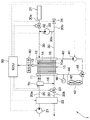
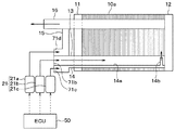
以下、本発明の第1実施形態に係る燃料電池システムについて図1〜図6を用いて説明する。この燃料電池システム1は例えば電気自動車に適用される。図1は本実施形態に係る燃料電池システム1の全体構成を示した図であり、図2は、燃料電池システム1の空気流路20を模式的に示した図である。
(First Embodiment)
Hereinafter, the fuel cell system according to the first embodiment of the present invention will be described with reference to FIGS. 1 to 6. This fuel cell system 1 is applied to, for example, an electric vehicle. FIG. 1 is a diagram showing the overall configuration of the fuel cell system 1 according to the present embodiment, and FIG. 2 is a diagram schematically showing an air flow path 20 of the fuel cell system 1.

図1に示すように、本実施形態の燃料電池システム1は、水素と酸素との電気化学反応を利用して電力を発生する燃料電池10を備えている。この燃料電池10は、図示しない電気負荷や2次電池等の電気機器に電力を供給するものである。因みに、電気自動車の場合、車両走行駆動源としての電動モータが電気負荷に相当している。 As shown in FIG. 1, the fuel cell system 1 of the present embodiment includes a fuel cell 10 that generates electric power by utilizing an electrochemical reaction between hydrogen and oxygen. The fuel cell 10 supplies electric power to an electric load (not shown) or an electric device such as a secondary battery. Incidentally, in the case of an electric vehicle, an electric motor as a vehicle traveling drive source corresponds to an electric load.

本実施形態では燃料電池10として固体高分子電解質型燃料電池を用いており、基本単位となるセル10aが集電板11、12の間に複数積層され、かつ電気的に直列接続されている。 In the present embodiment, a solid polymer electrolyte fuel cell is used as the fuel cell 10, and a plurality of cells 10a, which are basic units, are stacked between the current collector plates 11 and 12 and electrically connected in series.

燃料電池10の複数のセル10aでは、それぞれ、以下の水素と酸素の電気化学反応が起こり電気エネルギーが発生する。 In each of the plurality of cells 10a of the fuel cell 10, the following electrochemical reactions of hydrogen and oxygen occur to generate electric energy.

負極側:H2→2H++2e-
正極側:2H++1/2O2+2e-→H2
これにより、上記電気化学反応に伴って、複数のセル10aを通して集電板11、12の間には電流が流れる。集電板11、12のうち一方の集電板は、セル10aに対してその面方向に分散化して電流を供給し、他方の集電板は、セル10aにその面方向に分散して流れる電流を集める。
The negative side: H 2 → 2H + + 2e -
The positive side: 2H + + 1 / 2O 2 + 2e - → H 2 O
As a result, a current flows between the current collector plates 11 and 12 through the plurality of cells 10a in accordance with the electrochemical reaction. One of the current collector plates 11 and 12 is dispersed in the surface direction of the cell 10a to supply current, and the other current collector plate is dispersed in the cell 10a in the surface direction and flows. Collect current.

燃料電池システム1には、燃料電池10の空気極(正極)側に空気(酸素)を供給するための空気流路20と、燃料電池10の水素極(負極)側に水素を供給するための水素流路30が設けられている。ここで、空気流路20における燃料電池10より上流側を空気供給流路20aといい、下流側を空気排出路20bという。また、水素流路30における燃料電池10より上流側を水素供給流路30aといい、下流側を水素排出流路30bという。なお、空気は本発明の酸化剤ガスに相当し、水素は本発明の燃料ガスに相当している。 The fuel cell system 1 has an air flow path 20 for supplying air (oxygen) to the air electrode (positive electrode) side of the fuel cell 10 and hydrogen for supplying hydrogen to the hydrogen electrode (negative electrode) side of the fuel cell 10. A hydrogen flow path 30 is provided. Here, the upstream side of the air flow path 20 from the fuel cell 10 is referred to as an air supply flow path 20a, and the downstream side is referred to as an air discharge path 20b. Further, the upstream side of the hydrogen flow path 30 from the fuel cell 10 is referred to as a hydrogen supply flow path 30a, and the downstream side is referred to as a hydrogen discharge flow path 30b. Air corresponds to the oxidant gas of the present invention, and hydrogen corresponds to the fuel gas of the present invention.

空気供給流路20aの最上流部には、大気中から吸入した空気を燃料電池10に圧送するための空気ポンプ21が設けられ、空気供給流路20aにおける空気ポンプ21と燃料電池10との間には、空気への加湿を行う加湿器22と空気ポンプ21から圧送された空気を分流させるための空気分流機構70が設けられている。空気分流機構70は、流量調整部に相当する。また、空気排出路20bには、燃料電池10内の空気の圧力を調整するための空気調圧弁23が設けられている。 An air pump 21 for pumping air sucked from the atmosphere to the fuel cell 10 is provided at the most upstream portion of the air supply flow path 20a, and is between the air pump 21 and the fuel cell 10 in the air supply flow path 20a. Is provided with a humidifier 22 for humidifying the air and an air splitting mechanism 70 for splitting the air pumped from the air pump 21. The air diversion mechanism 70 corresponds to a flow rate adjusting unit. Further, the air discharge path 20b is provided with an air pressure regulating valve 23 for adjusting the pressure of the air in the fuel cell 10.

水素供給流路30aの最上流部には、水素が充填された高圧水素タンク31が設けられ、水素供給流路30aにおける高圧水素タンク31と燃料電池10との間には、燃料電池10に供給される水素の圧力を調整するための水素調圧弁32が設けられている。 A high-pressure hydrogen tank 31 filled with hydrogen is provided in the most upstream portion of the hydrogen supply flow path 30a, and is supplied to the fuel cell 10 between the high-pressure hydrogen tank 31 and the fuel cell 10 in the hydrogen supply flow path 30a. A hydrogen pressure regulating valve 32 is provided for adjusting the pressure of hydrogen to be produced.

水素排出流路30bには、水素供給流路30aにおける水素調圧弁32の下流側に接続されて閉ループを構成する水素循環流路30cが分岐して設けられており、これにより水素流路30内で水素を循環させて、未反応の水素を燃料電池10に再供給するようにしている。そして、水素循環流路30cには、水素流路30内で水素を循環させるための水素ポンプ33が設けられている。 The hydrogen discharge flow path 30b is provided with a branched hydrogen circulation flow path 30c connected to the downstream side of the hydrogen pressure regulating valve 32 in the hydrogen supply flow path 30a to form a closed loop, thereby forming the inside of the hydrogen flow path 30. Hydrogen is circulated in the fuel cell 10 to resupply unreacted hydrogen to the fuel cell 10. The hydrogen circulation flow path 30c is provided with a hydrogen pump 33 for circulating hydrogen in the hydrogen flow path 30.

燃料電池10は発電効率確保のために運転中一定温度(例えば80℃程度)に維持する必要がある。このため、燃料電池10を冷却するための冷却システムが設けられている。冷却システムには、燃料電池10に冷却水(熱媒体)を循環させる冷却水経路40、冷却水を循環させるウォータポンプ41、およびファン42を備えたラジエータ(放熱器)43が設けられている。 The fuel cell 10 needs to be maintained at a constant temperature (for example, about 80 ° C.) during operation in order to secure power generation efficiency. Therefore, a cooling system for cooling the fuel cell 10 is provided. The cooling system is provided with a cooling water path 40 for circulating cooling water (heat medium) in the fuel cell 10, a water pump 41 for circulating cooling water, and a radiator (radiator) 43 including a fan 42.

冷却水経路40には、冷却水をラジエータ52をバイパスさせるためのバイパス経路44が設けられている。冷却水経路40とバイパス経路44との合流点には、バイパス経路44に流れる冷却水流量を調整するための流路切替弁45が設けられている。また、冷却水経路40における燃料電池10の出口側近傍には、燃料電池10から流出した冷却水の温度を検出する温度検出手段としての温度センサ46が設けられている。この温度センサ46により冷却水温度Wtを検出することで、燃料電池10の温度を間接的に検出することができる。 The cooling water path 40 is provided with a bypass path 44 for bypassing the radiator 52 with the cooling water. At the confluence of the cooling water path 40 and the bypass path 44, a flow path switching valve 45 for adjusting the flow rate of the cooling water flowing through the bypass path 44 is provided. Further, a temperature sensor 46 as a temperature detecting means for detecting the temperature of the cooling water flowing out from the fuel cell 10 is provided in the vicinity of the outlet side of the fuel cell 10 in the cooling water path 40. By detecting the cooling water temperature Wt with the temperature sensor 46, the temperature of the fuel cell 10 can be indirectly detected.

燃料電池システム1は、各種制御を行う制御部(ECU)50およびセルモニタ60を備えている。制御部50は、CPU、ROM、RAM等からなる周知のマイクロコンピュータとその周辺回路にて構成されている。セルモニタ60は、セル10aから出力される電圧をセル10a毎に測定する。 The fuel cell system 1 includes a control unit (ECU) 50 that performs various controls and a cell monitor 60. The control unit 50 is composed of a well-known microcomputer including a CPU, ROM, RAM, and the like, and peripheral circuits thereof. The cell monitor 60 measures the voltage output from the cell 10a for each cell 10a.

制御部50は、セルモニタ60によって測定された各セル10aの電圧および温度センサ46の検出温度等に基づいて空気ポンプ21、加湿器22、空気分流機構70、空気調圧弁23、水素調圧弁32、水素ポンプ33、ウォータポンプ41、流路切替弁45を制御する。 The control unit 50 includes an air pump 21, a humidifier 22, an air diversion mechanism 70, an air pressure regulating valve 23, and a hydrogen pressure regulating valve 32, based on the voltage of each cell 10a measured by the cell monitor 60 and the detected temperature of the temperature sensor 46. It controls the hydrogen pump 33, the water pump 41, and the flow path switching valve 45.

図2、図3に示すように、空気分流機構70は、導入ポート71aと、第1〜第3導出ポート71b〜71dと、を有する筐体71を備えている。 As shown in FIGS. 2 and 3, the air diversion mechanism 70 includes a housing 71 having an introduction port 71a and first to third outlet ports 71b to 71d.

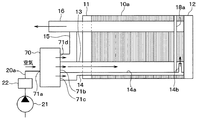
導入ポート71aは、加湿器22を介して空気ポンプ21に接続されている。第1導出ポート71bは、空気入口マニホールド13に接続され、第2導出ポート71cは、端部供給ライン14に接続され、第3導出ポート71dは、バイパスライン15に接続されている。なお、空気入口マニホールド13は、第1空気供給路に相当し、端部供給ライン14は、第2空気供給路に相当する。 The introduction port 71a is connected to the air pump 21 via the humidifier 22. The first lead-out port 71b is connected to the air inlet manifold 13, the second lead-out port 71c is connected to the end supply line 14, and the third lead-out port 71d is connected to the bypass line 15. The air inlet manifold 13 corresponds to the first air supply path, and the end supply line 14 corresponds to the second air supply path.

筐体71には、第1導出ポート71bから空気ポンプ21から圧送された空気が導入される。空気分流機構70は、導入ポート71aから導入された空気を、空気入口マニホールド13、端部供給ライン14およびバイパスライン15に供給する。空気分流機構70は、後述する制御部50からの信号に応じて、空気入口マニホールド13、端部供給ライン14およびバイパスライン15に供給する空気の流量を調整する。 The air pumped from the air pump 21 is introduced into the housing 71 from the first lead-out port 71b. The air diversion mechanism 70 supplies the air introduced from the introduction port 71a to the air inlet manifold 13, the end supply line 14, and the bypass line 15. The air distribution mechanism 70 adjusts the flow rate of air supplied to the air inlet manifold 13, the end supply line 14, and the bypass line 15 in response to a signal from the control unit 50 described later.

空気入口マニホールド13は、空気分流機構70より導入された空気を各セル10aのそれぞれに分配する。空気分流機構70より導入された空気は、空気入口マニホールド13を介して各セル10aの全体に供給される。 The air inlet manifold 13 distributes the air introduced from the air diversion mechanism 70 to each of the cells 10a. The air introduced from the air diversion mechanism 70 is supplied to the entire cells 10a via the air inlet manifold 13.

端部供給ライン14は、空気分流機構70より導入された空気を、各セル10aのうち集電板12側の端部に配置された複数の端部セル10aに向けて局所的に供給する。端部供給ライン14は、一端が空気分流機構70の第2導出ポート71cに接続され、他端が閉塞されたチューブ形状を成すチューブ部材14aを有している。チューブ部材14aにおける他端側の端部の近くの側面には、空気分流機構70の第2導出ポート71cから導入された空気を各セル10aのうち集電板12側の端部に配置された複数の端部セル10aに向けて吹き出す吹出口14bが設けられている。 The end supply line 14 locally supplies the air introduced from the air diversion mechanism 70 toward the plurality of end cells 10a arranged at the ends of the cells 10a on the current collector plate 12 side. The end supply line 14 has a tube member 14a having a tube shape in which one end is connected to the second outlet port 71c of the air diversion mechanism 70 and the other end is closed. On the side surface of the tube member 14a near the other end, air introduced from the second outlet port 71c of the air diversion mechanism 70 was arranged at the end of each cell 10a on the current collector plate 12 side. Air outlets 14b that blow out toward the plurality of end cells 10a are provided.

空気出口マニホールド16は、各セル10aから排出される生成水や不純物を空気とともに燃料電池10の外部へ排出する。各セル10aから排出される生成水、不純物、空気等は、空気出口マニホールド16を介して燃料電池10の外部へ排出される。 The air outlet manifold 16 discharges the generated water and impurities discharged from each cell 10a to the outside of the fuel cell 10 together with air. The generated water, impurities, air and the like discharged from each cell 10a are discharged to the outside of the fuel cell 10 via the air outlet manifold 16.

バイパスライン15は、空気分流機構70より導入された空気を、燃料電池10を迂回させて空気出口マニホールド16へ合流させる。空気出口マニホールド16は、例えば、氷点下で燃料電池システム1を始動する際に、空気出口マニホールド16に多く含まれる燃料ガスをバイパスライン15より導入された空気で希釈するために設けられている。 The bypass line 15 bypasses the fuel cell 10 and joins the air introduced from the air diversion mechanism 70 into the air outlet manifold 16. The air outlet manifold 16 is provided, for example, to dilute the fuel gas contained in the air outlet manifold 16 in large quantities with the air introduced from the bypass line 15 when starting the fuel cell system 1 below the freezing point.

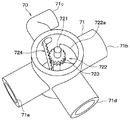
次に、空気分流機構70の構造について図3、図4を用いて説明する。図3に示すように、空気分流機構70は、筐体71、モータ721、回転弁722、ピニオンギア723およびシャット弁724を有している。モータ721、回転弁722、ピニオンギア723およびシャット弁724は、筐体71内に収納されている。なお、モータ721は、パルス信号の入力に応じて回転角度を制御するステッピングモータにより構成されている。 Next, the structure of the air diversion mechanism 70 will be described with reference to FIGS. 3 and 4. As shown in FIG. 3, the air diversion mechanism 70 includes a housing 71, a motor 721, a rotary valve 722, a pinion gear 723, and a shut valve 724. The motor 721, the rotary valve 722, the pinion gear 723, and the shut valve 724 are housed in the housing 71. The motor 721 is composed of a stepping motor that controls the rotation angle according to the input of the pulse signal.

筐体71は、導入ポート71aと、第1〜第3導出ポート71b〜71dと、を有している。 The housing 71 has an introduction port 71a and first to third out-licensing ports 71b to 71d.

回転弁722は、モータ721の回転軸に結合された扇形のロータリードアとして形成されている。回転弁722は、モータ721の回転軸を中心としてこの回転軸の軸周り方向に回動する。回転弁722は、円弧状の曲面部722aを有し、この曲面部722aにて、第1〜第3導出ポート71b〜71dの開度を調整する。ピニオンギア723は、モータ721の回転軸に固定されている。 The rotary valve 722 is formed as a fan-shaped rotary door coupled to the rotary shaft of the motor 721. The rotary valve 722 rotates around the rotary shaft of the motor 721 in the axial direction of the rotary shaft. The rotary valve 722 has an arcuate curved surface portion 722a, and the curved surface portion 722a adjusts the opening degree of the first to third lead-out ports 71b to 71d. The pinion gear 723 is fixed to the rotating shaft of the motor 721.

シャット弁724は、平板状の棒に歯すじが形成されたラックギア724aと、第2導出ポート71c内に配置され、ラックギア724aの一端に接続された弁機構724bと、を備えている。モータ721の回転軸の回転によりピニオンギア723に回転力が与えられると、ピニオンギア723に噛み合わされたラックギア724aが直線移動させられる。このラックギア724aの直線移動によりラックギア724aの一端に接続された弁機構724bが第2導出ポート71cを開閉する。シャット弁724は、回転弁722に連動して第2導出ポート71cを開閉する。 The shut valve 724 includes a rack gear 724a in which tooth streaks are formed on a flat plate-shaped rod, and a valve mechanism 724b arranged in a second lead-out port 71c and connected to one end of the rack gear 724a. When a rotational force is applied to the pinion gear 723 by the rotation of the rotation shaft of the motor 721, the rack gear 724a meshed with the pinion gear 723 is linearly moved. The linear movement of the rack gear 724a causes the valve mechanism 724b connected to one end of the rack gear 724a to open and close the second lead-out port 71c. The shut valve 724 opens and closes the second lead-out port 71c in conjunction with the rotary valve 722.

図4(a)〜(c)は、第1〜第3導出ポート71b〜71dにおける回転弁722とシャット弁724の状態を表している。 4 (a) to 4 (c) show the states of the rotary valve 722 and the shut valve 724 at the first to third lead-out ports 71b to 71d.

図4(a)は、回転弁722により第3導出ポート71dが閉じられ、第1導出ポート71bと第2導出ポート71cの開度が大となっている状態を表している。 FIG. 4A shows a state in which the third lead-out port 71d is closed by the rotary valve 722 and the opening degree of the first lead-out port 71b and the second lead-out port 71c is large.

図4(b)は、回転弁722により第3導出ポート71dが閉じられ、第1導出ポート71bの開度が大となり、弁機構724bにより第2導出ポート71cの開度が小となった状態を表している。 FIG. 4B shows a state in which the third outlet port 71d is closed by the rotary valve 722, the opening degree of the first outlet port 71b is large, and the opening degree of the second outlet port 71c is small by the valve mechanism 724b. Represents.

図4(c)は、回転弁722により第3導出ポート71dが閉じられ、弁機構724bによりシャット弁75により第2導出ポート71cが閉じられ、第1導出ポート71bの開度が大となった状態を表している。 In FIG. 4C, the rotary valve 722 closes the third lead-out port 71d, the valve mechanism 724b closes the second lead-out port 71c by the shut valve 75, and the opening degree of the first lead-out port 71b becomes large. It represents the state.

次に、本実施形態の燃料電池システム1の作動について説明する。 Next, the operation of the fuel cell system 1 of the present embodiment will be described.

制御部50は、アクセルペダルの操作量などに応じて燃料電池10の要求電力を算出するとともに、この算出される要求電力に燃料電池10から実際の出力される電力(以下、実際の電力という)を近づけるために、空気ポンプ21、加湿器22、空気分流機構70、空気調圧弁23、水素調圧弁32、水素ポンプ33、ウォータポンプ41、流路切替弁45を制御する通常時処理を行う。 The control unit 50 calculates the required power of the fuel cell 10 according to the amount of operation of the accelerator pedal and the like, and the power actually output from the fuel cell 10 to the calculated required power (hereinafter referred to as the actual power). In order to bring the air pump 21, the humidifier 22, the air diversion mechanism 70, the air pressure regulating valve 23, the hydrogen pressure regulating valve 32, the hydrogen pump 33, the water pump 41, and the flow path switching valve 45, a normal time process is performed.

ここで、要求電力は、燃料電池10から出力されることが要求される電力であって、アクセルペダルの操作量が大きくなるほど、要求電力が大きくなる。燃料電池10の実際の電力は、セルモニタ60により測定された各セル10aの電圧によって求められる。 Here, the required power is the power required to be output from the fuel cell 10, and the larger the operation amount of the accelerator pedal, the larger the required power. The actual power of the fuel cell 10 is determined by the voltage of each cell 10a measured by the cell monitor 60.

この際に、水素タンク31から燃料電池10に水素調圧弁32により調圧された水素が吐出する。水素ポンプ33は、水素供給流路30a→燃料電池10の複数のセル10a→水素排出流路30bの順に流れる水素の流れを発生させる。 At this time, hydrogen regulated by the hydrogen pressure regulating valve 32 is discharged from the hydrogen tank 31 to the fuel cell 10. The hydrogen pump 33 generates a flow of hydrogen that flows in the order of the hydrogen supply flow path 30a → the plurality of cells 10a of the fuel cell 10 → the hydrogen discharge flow path 30b.

これに伴い、水素排出流路30bは、燃料電池10の複数のセル10aから排出された反応水等の廃液を排気弁34を通して排出する。 Along with this, the hydrogen discharge flow path 30b discharges waste liquid such as reaction water discharged from the plurality of cells 10a of the fuel cell 10 through the exhaust valve 34.

空気ポンプ21は、大気中から空気を吸い込んでこの吸い込んだ空気を空気供給流路20aへ圧送する。空気供給流路20aに圧送された空気は、加湿器22により加湿された後、空気分流機構70に導入される。 The air pump 21 sucks air from the atmosphere and pumps the sucked air to the air supply flow path 20a. The air pumped into the air supply flow path 20a is humidified by the humidifier 22 and then introduced into the air diversion mechanism 70.

ここで、通常時、空気分流機構70は、空気供給流路20aより導入された空気の全量を空気入口マニホールド13に導入する。空気入口マニホールド13に流れ込んだ空気は、複数のセル10aのそれぞれに分配される。この分配された空気は、複数のセル10aのそれぞれを通過して空気出口マニホールド16に集合される。この集合された空気は、空気出口マニホールド16から空気排気流路20bに設けられた空気調圧弁23を通して排出される。 Here, at normal times, the air diversion mechanism 70 introduces the entire amount of air introduced from the air supply flow path 20a into the air inlet manifold 13. The air that has flowed into the air inlet manifold 13 is distributed to each of the plurality of cells 10a. The distributed air passes through each of the plurality of cells 10a and is collected in the air outlet manifold 16. The collected air is discharged from the air outlet manifold 16 through the air pressure regulating valve 23 provided in the air exhaust flow path 20b.

また、例えば、氷点下で燃料電池システム1を始動する際には、空気分流機構70は、空気入口マニホールド13に導入する空気の流量を減少させて各セル10aの発熱を促進させるとともに、バイパス経路44に導入する空気の流量を多くする。このとき、燃料ガスが空気極側に透過してきて空気出口マニホールド16に多量の燃料ガスが流れ込む。しかし、空気出口マニホールド16に流れ込んだ燃料ガスは、バイパス経路44に導入された空気で希釈されて外部に排出される。 Further, for example, when starting the fuel cell system 1 below the freezing point, the air diversion mechanism 70 reduces the flow rate of the air introduced into the air inlet manifold 13 to promote the heat generation of each cell 10a and the bypass path 44. Increase the flow rate of air introduced into. At this time, the fuel gas permeates to the air electrode side, and a large amount of fuel gas flows into the air outlet manifold 16. However, the fuel gas that has flowed into the air outlet manifold 16 is diluted with the air introduced into the bypass path 44 and discharged to the outside.

本実施形態の制御部は、例えば、複数のセル10aのうち集電板12側の端部に配置された複数の端部セル10aの電圧が目標電圧よりも低下した場合に、空気分流機構70から空気入口マニホールド13に導入される空気の流量を減少させるとともに、空気分流機構70から端部供給ライン14に導入される空気の流量を増加させる処理を実施する。 The control unit of the present embodiment is, for example, an air flow rate mechanism 70 when the voltage of the plurality of end cells 10a arranged at the ends of the plurality of cells 10a on the current collector plate 12 side is lower than the target voltage. The process of reducing the flow rate of the air introduced into the air inlet manifold 13 and increasing the flow rate of the air introduced from the air current collecting mechanism 70 into the end supply line 14 is performed.

図5に、この処理のフローチャートを示す。制御部50は、上記した通常時処理と並行して図5に示す処理を周期的に実施する。なお、各図面のフローチャートにおける各制御ステップは、制御部50が有する各種の機能実現部を構成している。 FIG. 5 shows a flowchart of this process. The control unit 50 periodically executes the process shown in FIG. 5 in parallel with the above-mentioned normal time process. Each control step in the flowchart of each drawing constitutes various function realization units included in the control unit 50.

まず、S100にて、端部セル10aの電圧を取得する。具体的には、セルモニタ60から集電板12側の端部セル10aの電圧を取得する。 First, in S100, the voltage of the end cell 10a is acquired. Specifically, the voltage of the end cell 10a on the current collector plate 12 side is acquired from the cell monitor 60.

次に、S102にて、端部セル10aの電圧が予め定められた目標電圧よりも低下しているか否かを判定する。 Next, in S102, it is determined whether or not the voltage of the end cell 10a is lower than the predetermined target voltage.

ここで、端部セル10aの電圧が予め定められた目標電圧以上となっている場合、空気分流機構70から空気入口マニホールド13に導入される空気の流量を変更することなく本処理を終了する。具体的には、空気分流機構70から空気入口マニホールド13に、空気分流機構70に導入された全ての空気が導入されるよう空気分流機構70を制御する。 Here, when the voltage of the end cell 10a is equal to or higher than a predetermined target voltage, this process ends without changing the flow rate of the air introduced from the air diversion mechanism 70 into the air inlet manifold 13. Specifically, the air diversion mechanism 70 is controlled so that all the air introduced into the air diversion mechanism 70 is introduced into the air inlet manifold 13 from the air diversion mechanism 70.

また、冷却されやすい端部セル10aに生成水の滞留が生じて端部セル10aの空気極に十分な空気を供給できない状態(フラッディング)になっており、端部セル10aの電圧が予め定められた目標電圧よりも低下している場合、S102の判定はYESとなり、S104にて、空気分流機構70から端部供給ライン14に流す空気の増加量Xを特定する。具体的には、目標電圧と端部セル10aの電圧の差分を変数とする関数Fを用いて端部供給ライン14に流す空気の増加量Xを特定する。なお、関数Fは、制御部50のROMに予め記憶されている。 In addition, the generated water stays in the end cell 10a, which is easily cooled, and sufficient air cannot be supplied to the air electrode of the end cell 10a (flooding), and the voltage of the end cell 10a is predetermined. If the voltage is lower than the target voltage, the determination in S102 is YES, and in S104, the increase amount X of the air flowing from the air diversion mechanism 70 to the end supply line 14 is specified. Specifically, the increase amount X of the air flowing through the end supply line 14 is specified by using the function F in which the difference between the target voltage and the voltage of the end cell 10a is used as a variable. The function F is stored in advance in the ROM of the control unit 50.

次に、空気入口マニホールド13に流れる空気の流量と端部供給ライン14に流れる空気の流量が、S104にて特定した増加量Xに基づく流量となるよう端部供給ライン14を制御する(S106)。具体的には、空気入口マニホールド13に流れる空気の流量は流量X分だけ減少し、端部供給ライン14に流れる空気の流量は流量X分だけ増加するよう端部供給ライン14を制御する。 Next, the end supply line 14 is controlled so that the flow rate of the air flowing through the air inlet manifold 13 and the flow rate of the air flowing through the end supply line 14 are the flow rates based on the increase amount X specified in S104 (S106). .. Specifically, the end supply line 14 is controlled so that the flow rate of the air flowing through the air inlet manifold 13 decreases by the flow rate X and the flow rate of the air flowing through the end supply line 14 increases by the flow rate X.

これにより、端部セル10aに生成水の滞留が生じて端部セル10aの電圧が目標電圧よりも低下したときに、空気入口マニホールド13から各セル10aに供給される空気の流量を低下させるとともに、端部供給ライン14を介して端部セル10aに供給する空気の流量が増加する。 As a result, when the generated water stays in the end cell 10a and the voltage of the end cell 10a drops below the target voltage, the flow rate of the air supplied from the air inlet manifold 13 to each cell 10a is reduced. , The flow rate of air supplied to the end cell 10a via the end supply line 14 increases.

なお、端部供給ライン14を介して端部セル10aに供給する空気の流量が増加するので、フラッディングが生じている端部セル10aに溜まった生成水を飛ばすことが可能となる。また、空気入口マニホールド13から各セル10aに供給される空気の流量を低下させるので、フラッディングが生じていないセル10aが乾いてしまうといったことを防止することも可能である。 Since the flow rate of the air supplied to the end cell 10a via the end supply line 14 increases, the generated water accumulated in the end cell 10a where flooding has occurred can be blown away. Further, since the flow rate of the air supplied from the air inlet manifold 13 to each cell 10a is reduced, it is possible to prevent the cell 10a without flooding from drying out.

図6は、空気分流機構70および端部供給ライン14を備えることなく空気入口マニホールド13から各セル10aに空気を供給する従来の燃料電池システムと、空気分流機構70、空気入口マニホールド13および端部供給ライン14を備えた本発明の燃料電池システムの空気過剰率に対するスタック電圧の特性を示した図である。なお、空気過剰率は、実際に供給された空気の質量を理論上必要な最少空気質量で除した値をいう。ここでは、燃料電池10の端部セル10aにフラッディングを生じさせた状態で、空気ポンプ21から圧送される空気の流量を変化させて空気過剰率を変化させている。 FIG. 6 shows a conventional fuel cell system that supplies air from an air inlet manifold 13 to each cell 10a without providing an air diversion mechanism 70 and an end supply line 14, an air diversion mechanism 70, an air inlet manifold 13, and an end. It is a figure which showed the characteristic of the stack voltage with respect to the excess air ratio of the fuel cell system of this invention provided with a supply line 14. The excess air ratio is a value obtained by dividing the mass of the actually supplied air by the theoretically required minimum mass of air. Here, the excess air ratio is changed by changing the flow rate of the air pumped from the air pump 21 in a state where the end cell 10a of the fuel cell 10 is flooded.

従来の燃料電池システムでは、特に、空気過剰率が1.1〜1.3程度のときにセル10全体の電圧が大きく低下している。これに対し、本実施形態の燃料電池システムでは、端部セル10aの電圧向上によりセル10a全体の電圧が上昇している。すなわち、本実施形態の燃料電池システムは、従来の燃料電池システムよりも発電効率が向上している。 In the conventional fuel cell system, the voltage of the entire cell 10 is greatly reduced, particularly when the excess air ratio is about 1.1 to 1.3. On the other hand, in the fuel cell system of the present embodiment, the voltage of the entire cell 10a rises due to the voltage improvement of the end cell 10a. That is, the fuel cell system of the present embodiment has improved power generation efficiency as compared with the conventional fuel cell system.

上記した構成によれば、燃料電池システムは、複数のセルのうち第1の範囲に向けて空気を供給する第1空気供給路13と、複数のセルのうち第1の範囲と異なる第2の範囲に向けて空気を供給する第2空気供給路14と、第1空気供給路に供給する空気の流量と第2空気供給路に供給する空気の流量を調整する流量調整部70と、を備えている。 According to the above configuration, the fuel cell system has a first air supply path 13 that supplies air to the first range of the plurality of cells and a second air supply path 13 that is different from the first range of the plurality of cells. A second air supply path 14 for supplying air toward a range, and a flow rate adjusting unit 70 for adjusting the flow rate of air supplied to the first air supply path and the flow rate of air supplied to the second air supply path are provided. ing.

このような構成によれば、複数のセルのうち第1の範囲に供給する空気の流量と、複数のセルのうち第1の範囲と異なる第2の範囲に向けて供給する空気の流量を調整することができ、複数のセルへ向けて適正に空気を供給することができる。 According to such a configuration, the flow rate of the air supplied to the first range of the plurality of cells and the flow rate of the air supplied to the second range different from the first range of the plurality of cells are adjusted. It is possible to properly supply air to a plurality of cells.

ここで、第1の範囲は、複数のセルの全体を含む範囲とし、第2の範囲は、複数のセルのうち少なくとも一方の端部に配置されたセルに対応する範囲とすることができる。 Here, the first range may be a range including the entire plurality of cells, and the second range may be a range corresponding to cells arranged at at least one end of the plurality of cells.

また、燃料電池システムは、空気を圧送する空気ポンプ21を備えている。また、流量調整部70は、空気ポンプ21から圧送された空気を導入する導入ポート71a、第1空気供給路13に空気を導出する第1導出ポート71bおよび第2空気供給路14に空気を導出する第2導出ポート71cを有する筐体71と、筐体71内に移動可能に配置され、第1導出ポート71bおよび第2導出ポート71cの開度を調整する流量調整機構721〜724と、を備えている。 The fuel cell system also includes an air pump 21 that pumps air. Further, the flow rate adjusting unit 70 leads out air to the introduction port 71a for introducing the air pumped from the air pump 21, the first outlet port 71b for leading out the air to the first air supply passage 13, and the second air supply passage 14. A housing 71 having a second lead-out port 71c, and a flow rate adjusting mechanism 721 to 724 movably arranged in the housing 71 to adjust the opening degree of the first lead-out port 71b and the second lead-out port 71c. I have.

このように、流量調整部70は、導入ポート71a、第1導出ポート71bおよび第2導出ポート71cを有する筐体71と、第1導出ポート71bおよび第2導出ポート71cの開度を調整する流量調整機構721〜724により構成することができる。 In this way, the flow rate adjusting unit 70 adjusts the opening degree of the housing 71 having the introduction port 71a, the first out-licensing port 71b and the second out-licensing port 71c, and the opening degree of the first out-licensing port 71b and the second out-licensing port 71c. It can be configured by adjusting mechanisms 721 to 724.

また、流量調整機構721〜724は、モータ721の回転軸を中心として該回転軸の回転軸周り方向に回動する回転弁722を有し、回転弁722の位置に応じて第1導出ポート71bおよび第2導出ポート71cの開度を調整することができる。 Further, the flow rate adjusting mechanisms 721 to 724 have a rotary valve 722 that rotates around the rotary shaft of the motor 721 in the direction around the rotary shaft of the rotary shaft, and the first lead-out port 71b is provided according to the position of the rotary valve 722. And the opening degree of the second lead-out port 71c can be adjusted.

(第2実施形態)
本発明の第2実施形態について図7を参照して説明する。上記第1実施形態の端部供給ライン14は、空気分流機構70より導入された空気を、各セル10aのうち集電板12側の端部に配置された複数の端部セル10aに向けて集中的に供給している。これに対し、本実施形態の端部供給ライン14は、図7に示すように、空気分流機構70より導入された空気を、各セル10aのうち集電板11側と集電板12側の両側の端部に配置された複数の端部セル10aに向けて集中的に供給する。
(Second Embodiment)
A second embodiment of the present invention will be described with reference to FIG. The end supply line 14 of the first embodiment directs the air introduced from the air diversion mechanism 70 toward a plurality of end cells 10a arranged at the ends of each cell 10a on the current collector plate 12 side. It is supplied intensively. On the other hand, in the end supply line 14 of the present embodiment, as shown in FIG. 7, the air introduced from the air diversion mechanism 70 is introduced from the current collecting plate 11 side and the current collecting plate 12 side of each cell 10a. It is intensively supplied toward a plurality of end cells 10a arranged at the ends on both sides.

端部供給ライン14は、チューブ部材14a、吹出口14bおよび吹出口14cを有している。吹出口14bは、空気分流機構70の第2導出ポート71cから導入された空気を各セル10aのうち集電板12側の端部に配置された複数の端部セル10aに向けて吹き出す。 The end supply line 14 has a tube member 14a, an outlet 14b and an outlet 14c. The air outlet 14b blows out the air introduced from the second outlet port 71c of the air diversion mechanism 70 toward the plurality of end cells 10a arranged at the ends of the cells 10a on the current collector plate 12 side.

吹出口14cは、空気分流機構70の第2導出ポート71cから導入された空気を各セル10aのうち集電板11側の端部に配置された複数の端部セル10aに向けて吹き出す。 The air outlet 14c blows out the air introduced from the second outlet port 71c of the air diversion mechanism 70 toward the plurality of end cells 10a arranged at the ends of the cells 10a on the current collector plate 11 side.

このように、端部供給ライン14は、空気分流機構70より導入された空気を、複数のセル10aのうち両方の端部に配置された複数のセル10aに向けて集中的に分配することもできる。 In this way, the end supply line 14 can also centrally distribute the air introduced from the air diversion mechanism 70 toward the plurality of cells 10a arranged at both ends of the plurality of cells 10a. it can.

(第3実施形態)
本発明の第3実施形態について図8を参照して説明する。本実施形態の燃料電池システムは、上記第1実施形態の燃料電池システムに対し、さらに、端部供給ライン14から供給される空気を集電板12側の端部セル10aへ案内する仕切板18aを備えている。
(Third Embodiment)
A third embodiment of the present invention will be described with reference to FIG. The fuel cell system of the present embodiment is a partition plate 18a that guides the air supplied from the end supply line 14 to the end cell 10a on the current collector plate 12 side with respect to the fuel cell system of the first embodiment. It has.

これによれば、仕切板18aにより端部供給ライン14から供給される空気が集電板12側の端部セル10a以外の部位へ流れ出るのが防止されるので、仕切板18aを設けていない場合と比較して集電板12側の端部セル10aへ十分な空気を供給することができる。 According to this, the air supplied from the end supply line 14 by the partition plate 18a is prevented from flowing out to a portion other than the end cell 10a on the current collector plate 12 side. Therefore, when the partition plate 18a is not provided. It is possible to supply sufficient air to the end cell 10a on the current collector plate 12 side as compared with the above.

(第4実施形態)
本発明の第4実施形態について図9を用いて説明する。本実施形態の燃料電池システムは、上記第2実施形態の燃料電池システムに対し、さらに、端部供給ライン14から供給される空気を集電板12側の端部セル10aへ案内する仕切板18aと、集電板11側の端部セル10aへ案内する仕切板18bを備えている。
(Fourth Embodiment)
A fourth embodiment of the present invention will be described with reference to FIG. The fuel cell system of the present embodiment is a partition plate 18a that guides the air supplied from the end supply line 14 to the end cell 10a on the current collector plate 12 side with respect to the fuel cell system of the second embodiment. And a partition plate 18b that guides the end cell 10a on the current collector plate 11 side.

これによれば、さらに、仕切板18bにより端部供給ライン14から供給される空気が集電板11側の端部セル10a以外の部位へ流れ出るのも防止されるので、集電板12側の端部セル10aへ十分な空気を供給することができる。 According to this, further, the air supplied from the end supply line 14 by the partition plate 18b is prevented from flowing out to a portion other than the end cell 10a on the current collector plate 11 side, so that the air on the current collector plate 12 side is further prevented. Sufficient air can be supplied to the end cell 10a.

(第5実施形態)
本発明の第5実施形態について図10を用いて説明する。上記第1〜第4実施形態の空気分流機構70は、モータ721の回転軸の回転に伴う回転弁722の回転およびシャット弁724の移動により空気入口マニホールド13、端部供給ライン14およびバイパスライン15に供給する空気の流量を調整している。これに対し、本実施形態の空気分流機構70は、ピニオンギア732および分流スリット731を有し、ピニオンギア732の回転に伴って分流スリット731が直線移動することにより空気入口マニホールド13、端部供給ライン14およびバイパスライン15に供給する空気の流量を調整する。なお、ピニオンギア732および分流スリット731は、流量調整機構に相当する。
(Fifth Embodiment)
A fifth embodiment of the present invention will be described with reference to FIG. The air diversion mechanism 70 of the first to fourth embodiments has the air inlet manifold 13, the end supply line 14, and the bypass line 15 due to the rotation of the rotary valve 722 and the movement of the shut valve 724 accompanying the rotation of the rotary shaft of the motor 721. The flow rate of air supplied to is adjusted. On the other hand, the air diversion mechanism 70 of the present embodiment has a pinion gear 732 and a diversion slit 731, and the diversion slit 731 linearly moves with the rotation of the pinion gear 732 to supply the air inlet manifold 13 and the end portion. The flow rate of air supplied to the line 14 and the bypass line 15 is adjusted. The pinion gear 732 and the diversion slit 731 correspond to the flow rate adjusting mechanism.

ピニオンギア732は、図示しないモータの回転軸に固定されている。分流スリット731は、板状を成している。分流スリット731の中央部には、表裏を貫通するスリット穴731aが形成されている。また、分流スリット731の一面には、歯すじが形成されている。 The pinion gear 732 is fixed to a rotating shaft of a motor (not shown). The diversion slit 731 has a plate shape. A slit hole 731a penetrating the front and back is formed in the central portion of the diversion slit 731. Further, a tooth streak is formed on one surface of the diversion slit 731.

モータの回転軸の回転の回転によりピニオンギア732に回転力が与えられると、ピニオンギア732と歯すじが噛み合わされた分流スリット731が直線移動させられる。この分流スリット731の直線移動により分流スリット731のスリット穴731aを通過する空気の流れが変更される。 When a rotational force is applied to the pinion gear 732 by the rotation of the rotation shaft of the motor, the diversion slit 731 in which the pinion gear 732 and the tooth streaks are engaged is linearly moved. The linear movement of the diversion slit 731 changes the flow of air passing through the slit hole 731a of the diversion slit 731.

このように、本実施形態の空気分流機構70は、空気を流すスリット731aが形成されるとともに直線移動させられる板状の分流スリット731を有しており、スリット731の位置に応じて第1導出ポート71bおよび第2導出ポート71cの開度を調整することができる。 As described above, the air diversion mechanism 70 of the present embodiment has a plate-shaped diversion slit 731 in which the slit 731a through which air flows is formed and is linearly moved, and the first derivation is performed according to the position of the slit 731. The opening degree of the port 71b and the second lead-out port 71c can be adjusted.

(第6実施形態)
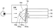
本発明の第6実施形態について図11〜図12を用いて説明する。本実施形態の空気分流機構70は、モータ742の回転軸に固定された分流スリット741を有している。分流スリット741は、三角形板状部材741aにより構成されている。三角形板状部材741aの一辺には、2つのガイド壁741bが立設されている。2つのガイド壁741bの間には、スリット741cが形成されている。
(Sixth Embodiment)
A sixth embodiment of the present invention will be described with reference to FIGS. 11 to 12. The air diversion mechanism 70 of the present embodiment has a diversion slit 741 fixed to the rotation shaft of the motor 742. The diversion slit 741 is composed of a triangular plate-shaped member 741a. Two guide walls 741b are erected on one side of the triangular plate-shaped member 741a. A slit 741c is formed between the two guide walls 741b.

モータ742の回転軸の回転により分流スリット741に回転力が与えられると、2つのガイド壁741bの間に形成されたスリット741cの位置が移動し、このスリット741cを通過する空気の流れが変更される。なお、分流スリット741およびモータ742は、流量調整機構に相当する。 When a rotational force is applied to the diversion slit 741 by the rotation of the rotation shaft of the motor 742, the position of the slit 741c formed between the two guide walls 741b moves, and the flow of air passing through the slit 741c is changed. Slit. The flow dividing slit 741 and the motor 742 correspond to the flow rate adjusting mechanism.

このように、本実施形態の空気分流機構70は、空気を流すスリット741aが形成されるとともにモータ721の回転軸を中心として該回転軸の回転軸周り方向に回動する分流スリット741を有している。そして、スリット741の位置に応じて第1導出ポート71bおよび第2導出ポート71cの開度を調整することができる。 As described above, the air diversion mechanism 70 of the present embodiment has a slit 741a for flowing air and a diversion slit 741 that rotates around the rotation axis of the motor 721 in the direction around the rotation axis of the rotation axis. ing. Then, the opening degrees of the first lead-out port 71b and the second lead-out port 71c can be adjusted according to the position of the slit 741.

(第7実施形態)
本発明の第7実施形態について図13を用いて説明する。上記第1実施形態の空気分流機構70は、ピニオンギア723によりモータ721の回転軸の回転運動をラックギア724aの直線運動に変換している。これに対し、本実施形態の空気分流機構70は、筐体71、回転弁722、リンク機構753、シャット弁724を有し、リンク機構753によりモータ721の回転軸の回転運動をシャット弁724の直線運動に変換している。なお、リンク機構753は流量調整機構を構成している。
(7th Embodiment)
A seventh embodiment of the present invention will be described with reference to FIG. The air diversion mechanism 70 of the first embodiment converts the rotational movement of the rotating shaft of the motor 721 into the linear motion of the rack gear 724a by the pinion gear 723. On the other hand, the air diversion mechanism 70 of the present embodiment includes a housing 71, a rotary valve 722, a link mechanism 753, and a shut valve 724, and the link mechanism 753 causes the rotary motion of the rotary shaft of the motor 721 to be shut by the shut valve 724. It is converted to linear motion. The link mechanism 753 constitutes a flow rate adjusting mechanism.

リンク機構753は、2つの板部材753a、753bを有している。板部材753aの一端は、モータ721の回転軸に固定され、板部材753aの他端は、板部材753bの一端とリベット等により接続されている。
シャット弁724は、平板状のラックギア724aと、第2導出ポート71c内に配置され、ラックギア724aの一端に接続された弁機構724bと、を備えている。ラックギア724aの一端は、弁機構724bに接続され、ラックギア724aの他端は、板部材753bの他端にリベット等により接続されている。
The link mechanism 753 has two plate members 753a and 753b. One end of the plate member 753a is fixed to the rotating shaft of the motor 721, and the other end of the plate member 753a is connected to one end of the plate member 753b by a rivet or the like.
The shut valve 724 includes a flat plate-shaped rack gear 724a and a valve mechanism 724b arranged in the second lead-out port 71c and connected to one end of the rack gear 724a. One end of the rack gear 724a is connected to the valve mechanism 724b, and the other end of the rack gear 724a is connected to the other end of the plate member 753b by a rivet or the like.

モータ721の回転軸の回転に伴って板部材753aが回動すると、その回動力は板部材753bによりラックギア724aに伝達される。なお、ラックギア724aはリンク機構752により直線移動させられ、ラックギア724aの一端接続された弁機構724bが第2導出ポート71cを開閉する。 When the plate member 753a rotates with the rotation of the rotation shaft of the motor 721, the rotational power is transmitted to the rack gear 724a by the plate member 753b. The rack gear 724a is linearly moved by the link mechanism 752, and the valve mechanism 724b connected to one end of the rack gear 724a opens and closes the second lead-out port 71c.

リンク機構752は、モータ721の回転軸の回転運動をラックギア724aの直線運動に変換する。すなわち、モータ721の回転軸の回転によりリンク機構753の板部材753aが回動すると、ラックギア724aは直線移動し、ラックギア724aの一端に接続された弁機構724bは第2導出ポート71cを開閉する。 The link mechanism 752 converts the rotational motion of the rotating shaft of the motor 721 into the linear motion of the rack gear 724a. That is, when the plate member 753a of the link mechanism 753 rotates due to the rotation of the rotation shaft of the motor 721, the rack gear 724a moves linearly, and the valve mechanism 724b connected to one end of the rack gear 724a opens and closes the second lead-out port 71c.

(第8実施形態)
本発明の第8実施形態について図14を用いて説明する。本実施形態の空気分流機構70は、筐体71、回転弁722、偏心カム763、シャット弁724を有し、偏心カム763によりモータ721の回転軸の回転運動をシャット弁724の直線運動に変換している。なお、偏心カム763は流量調整機構を構成している。
(8th Embodiment)
An eighth embodiment of the present invention will be described with reference to FIG. The air distribution mechanism 70 of the present embodiment includes a housing 71, a rotary valve 722, an eccentric cam 763, and a shut valve 724, and the eccentric cam 763 converts the rotary motion of the rotary shaft of the motor 721 into a linear motion of the shut valve 724. doing. The eccentric cam 763 constitutes a flow rate adjusting mechanism.

偏心カム763は、円盤状を成している。偏心カム763は、モータ721の回転軸に、該回転軸に対して偏心して取り付けられている。 The eccentric cam 763 has a disk shape. The eccentric cam 763 is attached to the rotating shaft of the motor 721 eccentrically with respect to the rotating shaft.

シャット弁724は、平板状のラックギア724aと、第2導出ポート71c内に配置され、ラックギア724aの一端に接続された弁機構724bと、を備えている。ラックギア724aの一端は、弁機構724bに接続され、ラックギア724aの他端は、図示しないバネ等により偏心カム763の側面に付勢されている。 The shut valve 724 includes a flat plate-shaped rack gear 724a and a valve mechanism 724b arranged in the second lead-out port 71c and connected to one end of the rack gear 724a. One end of the rack gear 724a is connected to the valve mechanism 724b, and the other end of the rack gear 724a is urged to the side surface of the eccentric cam 763 by a spring or the like (not shown).

偏心カム763は、モータ721の回転軸の回転運動をラックギア724aの直線運動に変換する。すなわち、モータ721の回転軸の回転により偏心カム763が回動すると、ラックギア724aは直線移動し、ラックギア724aの一端に接続された弁機構724bは第2導出ポート71cを開閉する。 The eccentric cam 763 converts the rotational motion of the rotating shaft of the motor 721 into a linear motion of the rack gear 724a. That is, when the eccentric cam 763 is rotated by the rotation of the rotation shaft of the motor 721, the rack gear 724a moves linearly, and the valve mechanism 724b connected to one end of the rack gear 724a opens and closes the second outlet port 71c.

(第9実施形態)
本発明の第9実施形態について図15〜図16を用いて説明する。本実施形態の空気分流機構70は、モータ772の回転軸に固定された分流スリット771を有している。分流スリット771は、底板部771aと、底板部771aの一面側に所定の間隔を設けて立設された2つのガイド部771bを有している。2つのガイド部771bの間にスリット771cが形成されている。
(9th Embodiment)
A ninth embodiment of the present invention will be described with reference to FIGS. 15 to 16. The air diversion mechanism 70 of the present embodiment has a diversion slit 771 fixed to the rotation shaft of the motor 772. The flow dividing slit 771 has a bottom plate portion 771a and two guide portions 771b erected on one surface side of the bottom plate portion 771a at a predetermined interval. A slit 771c is formed between the two guide portions 771b.

モータ772の回転軸の回転により分流スリット771に回転力が与えられると、2つのガイド部771bの間に形成されたスリット771cの位置が移動し、このスリット771cを通過する空気の流れが変更される。なお、分流スリット771およびモータ772は、流量調整機構を構成している。 When a rotational force is applied to the diversion slit 771 by the rotation of the rotation shaft of the motor 772, the position of the slit 771c formed between the two guide portions 771b is moved, and the flow of air passing through the slit 771c is changed. Slit. The flow dividing slit 771 and the motor 772 form a flow rate adjusting mechanism.

このように、本実施形態の空気分流機構70は、分流スリット771がモータ772の回転軸の軸周りに回動することにより空気入口マニホールド13、端部供給ライン14およびバイパスライン15に供給する空気の流量を調整することができる。 As described above, in the air diversion mechanism 70 of the present embodiment, the air split slit 771 rotates around the axis of the rotation shaft of the motor 772 to supply the air to the air inlet manifold 13, the end supply line 14, and the bypass line 15. The flow rate can be adjusted.

(第10実施形態)
本発明の第10実施形態について図17を用いて説明する。本実施形態の燃料電池システムは、3つの空気ポンプ21a〜21cを備えている。各空気ポンプ21a〜21cは、制御部50に接続されている。制御部50は、空気入口マニホールド13、端部供給ライン14およびバイパスライン15に供給する空気の流量を調整する。
(10th Embodiment)
The tenth embodiment of the present invention will be described with reference to FIG. The fuel cell system of this embodiment includes three air pumps 21a to 21c. Each of the air pumps 21a to 21c is connected to the control unit 50. The control unit 50 adjusts the flow rate of air supplied to the air inlet manifold 13, the end supply line 14, and the bypass line 15.

空気ポンプ21aは、バイパスライン15に空気を供給するものであり、空気ポンプ21bは、空気入口マニホールド13に空気を供給するものである。また、空気ポンプ21cは、端部供給ライン14に空気を供給するものである。 The air pump 21a supplies air to the bypass line 15, and the air pump 21b supplies air to the air inlet manifold 13. Further, the air pump 21c supplies air to the end supply line 14.

このように、空気入口マニホールド13、端部供給ライン14およびバイパスライン15に吸気を供給する空気ポンプ21a〜21cを備え、制御部50の制御により空気入口マニホールド13、端部供給ライン14およびバイパスライン15に供給する空気の流量を調整することもできる。 As described above, the air pumps 21a to 21c for supplying intake air to the air inlet manifold 13, the end supply line 14 and the bypass line 15 are provided, and the air inlet manifold 13, the end supply line 14 and the bypass line are controlled by the control unit 50. It is also possible to adjust the flow rate of the air supplied to 15.

(他の実施形態)
(1)上記各実施形態では、複数のセル10aの全体を含む範囲を第1の範囲とし、この第1の範囲に向けて空気入口マニホールド13から空気を供給するよう構成した。これに対し、必ずしも複数のセル10aの全体を含む範囲に向けて空気入口マニホールド13から空気を供給するよう構成しなくてもよい。
(Other embodiments)
(1) In each of the above embodiments, the range including the entire plurality of cells 10a is set as the first range, and air is supplied from the air inlet manifold 13 toward the first range. On the other hand, it is not always necessary to supply air from the air inlet manifold 13 to a range including the entire plurality of cells 10a.

(2)上記各実施形態では、空気入口マニホールド13に対して1つの端部供給ライン14を設けるようにしたが、2つ以上の端部供給ライン14を設けるようにしてもよい。 (2) In each of the above embodiments, one end supply line 14 is provided for the air inlet manifold 13, but two or more end supply lines 14 may be provided.

(3)上記各実施形態では、複数のセル10aのうち少なくとも一方の端部に配置されたセルに端部供給ライン14から空気を供給するよう構成にしたが、例えば、複数のセル10aのうち中央部に配置されたセルに端部供給ライン14から空気を供給するよう構成にしてもよい。 (3) In each of the above embodiments, air is supplied from the end supply line 14 to the cells arranged at at least one end of the plurality of cells 10a. For example, among the plurality of cells 10a. The cell arranged in the central portion may be configured to supply air from the end supply line 14.

なお、本発明は上記した実施形態に限定されるものではなく、特許請求の範囲に記載した範囲内において適宜変更が可能である。また、上記各実施形態は、互いに無関係なものではなく、組み合わせが明らかに不可な場合を除き、適宜組み合わせが可能である。また、上記各実施形態において、実施形態を構成する要素は、特に必須であると明示した場合および原理的に明らかに必須であると考えられる場合等を除き、必ずしも必須のものではないことは言うまでもない。また、上記各実施形態において、実施形態の構成要素の個数、数値、量、範囲等の数値が言及されている場合、特に必須であると明示した場合および原理的に明らかに特定の数に限定される場合等を除き、その特定の数に限定されるものではない。また、上記各実施形態において、構成要素等の材質、形状、位置関係等に言及するときは、特に明示した場合および原理的に特定の材質、形状、位置関係等に限定される場合等を除き、その材質、形状、位置関係等に限定されるものではない。 The present invention is not limited to the above-described embodiment, and can be appropriately modified within the scope of the claims. Further, the above-described embodiments are not unrelated to each other, and can be appropriately combined unless the combination is clearly impossible. Further, in each of the above embodiments, it goes without saying that the elements constituting the embodiment are not necessarily essential except when it is clearly stated that they are essential and when they are clearly considered to be essential in principle. No. Further, in each of the above embodiments, when numerical values such as the number, numerical values, amounts, and ranges of the constituent elements of the embodiment are mentioned, when it is clearly stated that they are particularly essential, and in principle, the number is clearly limited to a specific number. It is not limited to the specific number except when it is done. Further, in each of the above embodiments, when referring to the material, shape, positional relationship, etc. of the constituent elements, etc., except when specifically specified or when the material, shape, positional relationship, etc. are limited in principle. , The material, shape, positional relationship, etc. are not limited.

10 燃料電池
10a セル
11、12 集電板
13 空気入口マニホールド
14 端部供給ライン
15 バイパスライン
16 空気出口マニホールド
21 空気ポンプ
70 空気分流機構
71 筐体
71a 第1導入ポート
71b 第2導入ポート
71c 第3導入ポート
10 Fuel cell 10a Cell 11, 12 Current collector 13 Air inlet manifold 14 End supply line 15 Bypass line 16 Air outlet manifold 21 Air pump 70 Air diversion mechanism 71 Housing 71a 1st introduction port 71b 2nd introduction port 71c 3rd Introductory port

Claims (6)

空気に含まれる酸素と燃料ガスの電気化学反応により電気エネルギーを出力するセル(10a)を複数積層してなる燃料電池(10)を備た燃料電池システムであって、
複数の前記セルのうち第1の範囲に向けて前記空気を供給する第1空気供給路(13)と、
複数の前記セルのうち前記第1の範囲と異なる第2の範囲に向けて前記空気を供給する第2空気供給路(14)と、
複数の前記セルを迂回させるよう前記空気を流すバイパスライン(15)と、
前記第1空気供給路に供給する前記空気の流量と前記第2空気供給路に供給する前記空気の流量を調整する流量調整部(70)と、
前記空気を圧送する空気ポンプ(21)と、を備え、
前記流量調整部は、
前記空気ポンプから圧送された前記空気を導入する導入ポート(71a)、前記第1空気供給路に前記空気を導出する第1導出ポート(71b)、前記第2空気供給路に前記空気を導出する第2導出ポート(71c)および前記バイパスラインに前記空気を導出する第3導出ポート(71d)と、を有する筐体(71)と、
前記筐体内に移動可能に配置され、前記第1導出ポート、前記第2導出ポートおよび前記第3導出ポートの開度を調整する流量調整機構(721〜724、731〜732、741〜742、753、763、771〜772)と、を有している燃料電池システム。
A fuel cell system example Bei cell fuel cell (10) of the (10a) formed by stacking a plurality of output electric energy by the electrochemical reaction of oxygen and fuel gas contained in the air,
A first air supply path (13) for supplying the air toward the first range of the plurality of cells,
A second air supply path (14) for supplying the air to a second range different from the first range among the plurality of cells.
A bypass line (15) through which the air flows so as to bypass the plurality of cells,
A flow rate adjusting unit (70) that adjusts the flow rate of the air supplied to the first air supply path and the flow rate of the air supplied to the second air supply path.
An air pump (21) for pumping the air is provided.
The flow rate adjusting unit
An introduction port (71a) for introducing the air pumped from the air pump, a first outlet port (71b) for leading the air to the first air supply path, and the air being led out to the second air supply path. A housing (71) having a second lead-out port (71c) and a third lead-out port (71d) for leading out the air to the bypass line.
Flow rate adjusting mechanisms (721-724, 731-732, 741-742, 753) that are movably arranged in the housing and adjust the opening degrees of the first lead-out port, the second lead-out port, and the third lead-out port. , 763, 771-772), and a fuel cell system.
前記第1の範囲は、複数の前記セルの全体を含む範囲であり、
前記第2の範囲は、複数の前記セルのうち少なくとも一方の端部に配置された前記セルに対応する範囲である請求項1に記載の燃料電池システム。
The first range is a range including the entire plurality of the cells.
The fuel cell system according to claim 1, wherein the second range corresponds to the cell arranged at at least one end of the plurality of cells.
前記流量調整機構は、モータ(721、771)の回転軸を中心として該回転軸の回転軸周り方向に回動する回転弁(722、771)を有し、
前記回転弁の位置に応じて前記第1導出ポートおよび前記第2導出ポートの開度を調整する請求項に記載の燃料電池システム。
The flow rate adjusting mechanism has a rotary valve (722, 771) that rotates around the rotary shaft of the motor (721, 771) in a direction around the rotary shaft of the rotary shaft.
The fuel cell system according to claim 2 , wherein the opening degrees of the first lead-out port and the second lead-out port are adjusted according to the position of the rotary valve.
前記流量調整機構は、前記空気を流すスリット(731a)が形成されるとともに直線移動させられる板状の分流スリット(731)を有し、
前記スリットの位置に応じて前記第1導出ポートおよび前記第2導出ポートの開度を調整する請求項に記載の燃料電池システム。
The flow rate adjusting mechanism has a plate-shaped diversion slit (731) in which the slit (731a) through which the air flows is formed and is linearly moved.
The fuel cell system according to claim 2 , wherein the opening degree of the first outlet port and the second outlet port is adjusted according to the position of the slit.
前記流量調整機構は、前記空気を流すスリット(741a)が形成されるとともにモータ(721、771)の回転軸に連動して回動する分流スリット(741)を有し、
前記スリットの位置に応じて前記第1導出ポートおよび前記第2導出ポートの開度を調整する請求項に記載の燃料電池システム。
The flow rate adjusting mechanism has a flow dividing slit (741) in which the slit (741a) through which the air flows is formed and rotates in conjunction with the rotation axis of the motors (721, 771).
The fuel cell system according to claim 2 , wherein the opening degrees of the first lead-out port and the second lead-out port are adjusted according to the position of the slit.
複数の前記セルから前記電気化学反応により生成された生成水を含む前記空気を外部へ排出する空気排出路(20b)と、
前記第1空気供給路から前記燃料電池を迂回させて前記空気排出路に前記空気を排出するバイパス路(15)と、を備え、
前記流量調整部は、前記第1空気供給路に供給する前記空気の流量、前記第2空気供給路に供給する前記空気の流量および前記バイパス路に供給する前記空気の流量を調整する請求項に記載の燃料電池システム。
Air discharge passage for discharging the air including the plurality of the cells the electrochemical reaction water produced by the incoming and (20b),
A bypass path (15) for bypassing the fuel cell from the first air supply path and discharging the air to the air discharge path is provided.
The flow rate adjusting unit, the flow rate of the air supplied to the first air supply passage, claim 2 for regulating the flow rate of the air supplied to the flow rate and the bypass passage of the air supplied to the second air supply passage The fuel cell system described in.
JP2017047476A 2017-03-13 2017-03-13 Fuel cell system Active JP6780552B2 (en)

Priority Applications (1)

Application Number Priority Date Filing Date Title
JP2017047476A JP6780552B2 (en) 2017-03-13 2017-03-13 Fuel cell system

Applications Claiming Priority (1)

Application Number Priority Date Filing Date Title
JP2017047476A JP6780552B2 (en) 2017-03-13 2017-03-13 Fuel cell system

Publications (2)

Publication Number Publication Date
JP2018152235A JP2018152235A (en) 2018-09-27
JP6780552B2 true JP6780552B2 (en) 2020-11-04

Family

ID=63679657

Family Applications (1)

Application Number Title Priority Date Filing Date
JP2017047476A Active JP6780552B2 (en) 2017-03-13 2017-03-13 Fuel cell system

Country Status (1)

Country Link
JP (1) JP6780552B2 (en)

Families Citing this family (1)

* Cited by examiner, † Cited by third party
Publication number Priority date Publication date Assignee Title
CN113270615A (en) * 2020-02-14 2021-08-17 广州汽车集团股份有限公司 Air humidifier and fuel cell vehicle

Family Cites Families (7)

* Cited by examiner, † Cited by third party
Publication number Priority date Publication date Assignee Title
EP1623478A2 (en) * 2003-05-15 2006-02-08 Nissan Motor Company, Limited Prevention of flooding of fuel cell stack
JP2005085531A (en) * 2003-09-05 2005-03-31 Nissan Motor Co Ltd Fuel cell system
JP2005174645A (en) * 2003-12-09 2005-06-30 Nissan Motor Co Ltd Fuel cell system
KR101124985B1 (en) * 2009-06-19 2012-03-27 현대자동차주식회사 Integrated valve for fuel cell stack
JP5818014B2 (en) * 2012-04-04 2015-11-18 トヨタ自動車株式会社 Fuel cell system
JP5761110B2 (en) * 2012-04-11 2015-08-12 株式会社デンソー Fuel cell system
JP6221426B2 (en) * 2013-07-05 2017-11-01 アイシン精機株式会社 Fluid control valve

Also Published As

Publication number Publication date
JP2018152235A (en) 2018-09-27

Similar Documents

Publication Publication Date Title
US9735437B2 (en) Wet state control device for fuel cell
JP6206440B2 (en) Fuel cell system
CN103534857B (en) The coolant temperature adjustment System of fuel cell and thermostat valve
US10862145B2 (en) Humidifying device for fuel cell
JP4701624B2 (en) Fuel cell system
JP6322712B2 (en) Pressure adjustment method
CN101790813A (en) Fuel cell system, and its control method
JP5834594B2 (en) Fuel cell wet state control device
CN111613815A (en) Fuel cell hydrogen circulation system and control method thereof
JP6780552B2 (en) Fuel cell system
JP5583902B2 (en) Fuel cell system
JP2016035870A (en) Fuel battery system
KR101966449B1 (en) Air supply device for fuel cell system and method for adjusting pressure of air blower
JP2014089813A (en) Fuel cell system
EP3118922B1 (en) Fuel cell system
JP2014007097A (en) Fuel cell system
KR101836257B1 (en) Fuel cell stack and method for removing flooding in the stack
JP5982825B2 (en) Fuel cell system
JP5790177B2 (en) Fuel cell system
CN110137546A (en) Fuel cell system
JP2015170440A (en) fuel cell system
CN114665123B (en) Fuel cell stack and control system thereof
KR101405649B1 (en) Hydrogenre circulation device for fuel cell system
KR20220144099A (en) Condensate water discharge control device for fuel cell stack
JP2004039541A (en) Fuel cell

Legal Events

Date Code Title Description
A621 Written request for application examination

Free format text: JAPANESE INTERMEDIATE CODE: A621

Effective date: 20190718

A977 Report on retrieval

Free format text: JAPANESE INTERMEDIATE CODE: A971007

Effective date: 20200529

A131 Notification of reasons for refusal

Free format text: JAPANESE INTERMEDIATE CODE: A131

Effective date: 20200616

A521 Request for written amendment filed

Free format text: JAPANESE INTERMEDIATE CODE: A523

Effective date: 20200807

TRDD Decision of grant or rejection written
A01 Written decision to grant a patent or to grant a registration (utility model)

Free format text: JAPANESE INTERMEDIATE CODE: A01

Effective date: 20200915

A61 First payment of annual fees (during grant procedure)

Free format text: JAPANESE INTERMEDIATE CODE: A61

Effective date: 20200928

R150 Certificate of patent or registration of utility model

Ref document number: 6780552

Country of ref document: JP

Free format text: JAPANESE INTERMEDIATE CODE: R150

R250 Receipt of annual fees

Free format text: JAPANESE INTERMEDIATE CODE: R250