JP6780065B2 - Radiation imaging system and radiography imaging method - Google Patents
Radiation imaging system and radiography imaging method Download PDFInfo
- Publication number
- JP6780065B2 JP6780065B2 JP2019119134A JP2019119134A JP6780065B2 JP 6780065 B2 JP6780065 B2 JP 6780065B2 JP 2019119134 A JP2019119134 A JP 2019119134A JP 2019119134 A JP2019119134 A JP 2019119134A JP 6780065 B2 JP6780065 B2 JP 6780065B2
- Authority
- JP
- Japan
- Prior art keywords
- image
- radiation
- defect
- radiation detection
- row
- Prior art date
- Legal status (The legal status is an assumption and is not a legal conclusion. Google has not performed a legal analysis and makes no representation as to the accuracy of the status listed.)
- Active
Links
- 230000005855 radiation Effects 0.000 title claims description 450
- 238000002601 radiography Methods 0.000 title claims description 41
- 238000003384 imaging method Methods 0.000 title claims description 22
- 238000001514 detection method Methods 0.000 claims description 282
- 230000007547 defect Effects 0.000 claims description 155
- 238000012545 processing Methods 0.000 claims description 85
- 238000003702 image correction Methods 0.000 claims description 71
- 238000012937 correction Methods 0.000 claims description 45
- 230000002950 deficient Effects 0.000 claims description 44
- 230000015572 biosynthetic process Effects 0.000 claims description 33
- 238000003786 synthesis reaction Methods 0.000 claims description 33
- 238000000034 method Methods 0.000 claims description 27
- 230000002194 synthesizing effect Effects 0.000 claims description 26
- 230000001678 irradiating effect Effects 0.000 claims description 10
- 239000000203 mixture Substances 0.000 claims description 5
- 238000002156 mixing Methods 0.000 claims description 2
- 238000003672 processing method Methods 0.000 claims 8
- 239000002131 composite material Substances 0.000 description 7
- 238000006243 chemical reaction Methods 0.000 description 5
- 239000000758 substrate Substances 0.000 description 5
- 238000010586 diagram Methods 0.000 description 3
- 239000002184 metal Substances 0.000 description 3
- 229910052751 metal Inorganic materials 0.000 description 3
- 239000000853 adhesive Substances 0.000 description 2
- 230000001070 adhesive effect Effects 0.000 description 2
- 210000003141 lower extremity Anatomy 0.000 description 2
- 239000000463 material Substances 0.000 description 2
- 210000000278 spinal cord Anatomy 0.000 description 2
- 238000012935 Averaging Methods 0.000 description 1
- 229910021417 amorphous silicon Inorganic materials 0.000 description 1
- 238000004458 analytical method Methods 0.000 description 1
- 238000013459 approach Methods 0.000 description 1
- 238000003745 diagnosis Methods 0.000 description 1
- 238000010191 image analysis Methods 0.000 description 1
- 239000004575 stone Substances 0.000 description 1
- 239000000126 substance Substances 0.000 description 1
- 238000002834 transmittance Methods 0.000 description 1
- 238000009966 trimming Methods 0.000 description 1
- PICXIOQBANWBIZ-UHFFFAOYSA-N zinc;1-oxidopyridine-2-thione Chemical class [Zn+2].[O-]N1C=CC=CC1=S.[O-]N1C=CC=CC1=S PICXIOQBANWBIZ-UHFFFAOYSA-N 0.000 description 1
Images


Description
本発明は、放射線を用いて撮影を行う放射線撮影システム及び放射線撮影方法に関するものである。 The present invention relates to a radiographic imaging system and a radiographic imaging method for photographing using radiation.
近年、例えば医療分野では被検者の脊髄や下肢の全体や全身を撮影するといった、観察領域が広い撮影(以下、長尺撮影と称する)が行われている。特許文献1には、複数の放射線検出装置(放射線撮影装置)を並べて撮影することで、長尺撮影を行うことができる放射線撮影システムが開示されている。
In recent years, for example, in the medical field, imaging with a wide observation area (hereinafter referred to as long imaging) such as imaging the entire spinal cord or lower limbs of a subject or the whole body has been performed.
特許文献1において、放射線検出装置の一部を重ねながら複数の放射線検出装置を並べて撮影する際、放射線発生部から遠い位置に配置された放射線検出装置に放射線発生部に近い位置に配置された放射線検出装置の一部が写り込んでしまう。すなわち、一方の放射線検出装置が出力する放射線画像には他方の放射線検出装置の構造物が写り込む。放射線検出装置の構造物は、診断対象である被検者とは関係のない構造であり、欠陥領域といえる。欠陥領域は、複数の放射線画像を合成して長尺画像(合成画像)としても残ってしまう。しかしながら、特許文献1には、この写り込みに対する対策については言及されていない。
In
そこで本発明は、放射線検出装置の構造物に起因する欠陥領域を含んだ長尺画像の画質を向上させる放射線撮影システム及び放射線撮影方法を提供することを目的とする。 Therefore, an object of the present invention is to provide a radiography system and a radiography method for improving the image quality of a long image including a defect region caused by a structure of a radiation detection device.
本発明の目的を達成する放射線撮影システムは、放射線を検出する複数の放射線検出装置と、複数の放射線検出装置から取得される複数の放射線画像の拡大率を調整して合成することにより長尺画像を生成する合成処理部と、一方の放射線検出装置から取得される放射線画像から他方の放射線検出装置の構造情報を示す欠陥領域を取得する欠陥領域取得部と、前記長尺画像における、前記欠陥領域を補正する画像補正部と、を備える。 A radiography system that achieves the object of the present invention is a long image by adjusting and synthesizing a plurality of radiation detection devices for detecting radiation and a plurality of radiation images acquired from the plurality of radiation detection devices. A defect region acquisition unit that acquires a defect region showing structural information of the other radiation detection device from a radiation image acquired from one radiation detection device, and a defect region acquisition unit in the long image. It is provided with an image correction unit for correcting the above.
本発明によれば、放射線検出装置の構造物に起因する欠陥領域を含んだ長尺画像(合成画像)の画質を向上させることができる。 According to the present invention, it is possible to improve the image quality of a long image (composite image) including a defect region caused by the structure of the radiation detection device.
以下、添付図面を参照して本発明の好適な実施形態について説明する。 Hereinafter, preferred embodiments of the present invention will be described with reference to the accompanying drawings.
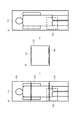
図1は、本発明の放射線撮影システムの概略構成を示す図である。複数の放射線検出装置を並べて行われる長尺撮影に用いられる放射線撮影システムの概略構成を示す図である。 FIG. 1 is a diagram showing a schematic configuration of the radiography system of the present invention. It is a figure which shows the schematic structure of the radiation imaging system used for long-length imaging performed by arranging a plurality of radiation detection devices side by side.
放射線撮影システムは、放射線を発生させる放射線発生部112を備えている。放射線発生部112は、照射範囲114に放射線を照射することができる。放射線発生部112は、床面又は天井に設置された支持部(図示しない。)を介して設置されている。放射線発生部112の照射面には、放射線を遮蔽する絞り(図示しない。)が設置されている。操作者は、放射線を遮蔽する絞りを制御することにより、放射線発生部112から照射される放射線の照射範囲114を設定することができる。
The radiography system includes a radiation generating
放射線撮影システムは、複数の放射線検出装置120、122、124を備えている。ここでは、3つの放射線検出装置120、122、124を備えた形態を示すが、2つの放射線検出装置、4つ以上の放射線検出装置であってもよい。複数の放射線検出装置120、122、124は、被検者100を通過した放射線を検出し、放射線に応じた画像データを出力するものである。なお、画像データを放射線画像と言い換えることもできる。
The radiography system includes a plurality of
具体的には、複数の放射線検出装置120、122、124は、被検者を透過した放射線を、透過放射線量に相当する電荷として検出する。例えば、複数の放射線検出装置120、122、124には、放射線を電荷に変換するa−Seなどの放射線を直接的に電荷に変換する直接変換型センサや、CsIなどのシンチレータとa−Siなどの光電変換素子を用いた間接型センサが用いられる。さらに、複数の放射線検出装置120、122、124は、検出された電荷をA/D変換することにより、画像データを生成し、画像表示制御部130へ出力する。
Specifically, the plurality of
複数の放射線検出装置は、撮影台110内に収納されている。撮影台110は、矩形の筐体であり、筐体内は中空である。また、撮影台110は、複数の放射線検出装置120、122、124を保持する機能を有している。
The plurality of radiation detection devices are housed in the photographing table 110. The shooting table 110 is a rectangular housing, and the inside of the housing is hollow. Further, the photographing table 110 has a function of holding a plurality of
図1に示すように、撮影台110を床面に対して直立させ、撮影台110が設置される。被検者100は、撮影台110の長手方向に沿って設置される。撮影台110は、被検者100を支える支持機能を有している。
As shown in FIG. 1, the photographing table 110 is set upright with respect to the floor surface, and the photographing table 110 is installed. The
図1では、撮影台110の長手方向が鉛直方向となるように、すなわち、撮影台110が床面に対して直立するように撮影台110が設置される。なお、撮影台110の長手方向が水平方向となるように、すなわち、撮影台110が床面に対して平行となるように撮影台110が設置されてもよい。 In FIG. 1, the photographing table 110 is installed so that the longitudinal direction of the photographing table 110 is the vertical direction, that is, the photographing table 110 stands upright with respect to the floor surface. The photographing table 110 may be installed so that the longitudinal direction of the photographing table 110 is horizontal, that is, the photographing table 110 is parallel to the floor surface.
撮影台110には、放射線検出装置120、放射線検出装置122、放射線検出装置124が撮影台110の長手方向に沿ってそれぞれ配置される。このとき、放射線検出装置の一部を重ねながら複数の放射線検出装置が配置される。例えば、図1に示すように、放射線検出装置120と放射線検出装置122は、一部が空間的に互いに重なるように配置される。このとき、放射線検出装置120と放射線検出装置122の撮影可能領域は互いに重なっている。同様にして、放射線検出装置122と放射線検出装置124は、一部が空間的に互いに重なるように配置される。このとき、放射線検出装置122と放射線検出装置124の撮影可能領域は互いに重なっている。また、放射線検出装置122は、放射線検出装置120と放射線検出装置124の背面側、つまり放射線発生部112から遠い位置に配置されている。
A
また、放射線撮影システムは、放射線検出装置から出力された画像データに対して画像処理を行ない、画像を生成する画像表示制御部130と、画像を表示する表示部132と、操作者から指示を行うための操作部134とを備えている。また、画像表示制御部130は、各構成要素を制御する機能を有している。
In addition, the radiography system performs image processing on the image data output from the radiation detection device, and gives instructions from the operator to the image
画像表示制御部130は、複数の放射線検出装置120、122、124に接続されている。具体的には、画像表示制御部130は、複数の放射線検出装置120、122、124と有線または無線のネットワークもしくは専用線で接続されている。複数の放射線検出装置120、122、124は、放射線発生部112で発生した放射線を撮像し、画像データを画像表示制御部130に出力する。画像表示制御部130は、コンピュータ上で動作するアプリケーション機能を有している。画像表示制御部130は、複数の放射線検出装置120、122、124の動作を制御しつつ、表示部132へ画像を出力したり、グラフィカルユーザーインターフェースを出力したりする。
The image
画像表示制御部130は、放射線発生部112の放射線を発生するタイミングと放射線の撮影条件を制御する。また、画像表示制御部130は、複数の放射線検出装置120、122、124の画像データを撮影するタイミング及び出力するタイミングを制御する。画像表示制御部130は、複数の放射線検出装置120、122、124に対して同時に撮影を行わせ、複数の放射線検出装置120、122、124に対して同時に画像データを出力させることができる。
The image
画像表示制御部130は、複数の放射線検出装置120、122、124から出力された画像データに対して、ノイズ除去などの画像処理を行う機能を有している。また、画像表示制御部130は、複数の放射線検出装置120、122、124から出力された画像に対してトリミングや回転といった画像処理を行なうこともできる。表示部132は、画像表示制御部130から出力される当該画像を表示させる。
The image
被検者100は、撮影台110に置かれた踏み台上に立ち、複数の放射線検出装置120、122、124および放射線発生部112に対して位置決めされる。本実施例では、放射線検出装置122の中心に垂直に放射線が入射する角度となっている。放射線発生部112から複数の放射線検出装置120、122、124に向け照射された放射線は、被検者100を透過して複数の放射線検出装置120、122、124に到達して検出される。複数の放射線検出装置120、122、124で得られた画像データは、画像表示制御部130で合成処理され、被検者100の合成画像が生成される。合成画像は、観察領域が広い長尺撮影によって取得される長尺画像である。表示部132は、画像表示制御部130から出力される長尺画像を表示させる。
The subject 100 stands on a stepping stone placed on the photographing table 110 and is positioned with respect to the plurality of
本発明の放射線撮影システムでは、1回の放射線の照射によって、被検者100の脊髄や下肢の全体や全身を撮影する長尺撮影を行うことができる。放射線発生部112から照射される放射線(照射範囲114)が複数の放射線検出装置120、122、124に同時に照射される。例えば、操作者は、放射線を遮蔽する絞りを制御したり、複数の放射線検出装置120、122、124と放射線発生部112との距離を調整したりする。
In the radiography system of the present invention, it is possible to perform long-length radiography in which the entire spinal cord and lower limbs of the subject 100 or the whole body is photographed by one irradiation of radiation. The radiation (irradiation range 114) emitted from the
なお、複数の放射線検出装置120、122、124は、放射線発生部112からの放射線の照射を自動検知する検知機能を有していてもよい。自動検知する検知機能は、放射線発生部112から放射線が照射された際、複数の放射線検出装置120、122、124が放射線を検知して放射線に起因する電荷を蓄積する機能である。複数の放射線検出装置120、122、124のいずれかに1つより放射線の照射を検知した際、複数の放射線検出装置120、122、124は、本読み動作を開始させて画像データを取得する。
The plurality of
上述した放射線撮影システムでは、放射線検出装置120、124の背後に放射線検出装置122が重なり合うように配置されている。このため、放射線検出装置122が出力する画像データには、放射線検出装置120、124の内部構成要素である放射線検出パネル、基板、筐体などの構造物(構造情報)が写り込んだ欠陥領域が生じる。この欠陥領域について、本発明の放射線撮影システムの放射線検出装置と放射線画像の関係を示す図2を用いて説明する。
In the above-mentioned radiography system, the
放射線検出装置120は、放射線入射面側から、放射線を検出する放射線検出パネル150、放射線検出パネル150を粘着してパネル基台158に設置させる粘着材156と、放射線検出パネル150を支持するパネル基台158、放射線検出パネル150から電気信号を出力させる制御基板154の順に積層された結合体が内包される。放射線検出パネル150と制御基板154は、フレキシブル基板152を介して接続されている。
The
また、放射線検出装置120の外装筺体は、金属から成る金属筺体160と、放射線を透過させる放射線透過部材から成る放射線透過部162とから構成される。放射線検出パネル150の放射線入射面には、放射線透過部162が設置され、放射線発生部112からの放射線の減衰を抑える。放射線検出パネル150は、放射線を検出可能な有効画素領域と、該有効画素領域の外周に辺縁部を有する。
Further, the exterior housing of the
なお、説明は省略するが、放射線検出装置122及び放射線検出装置124は、放射線検出装置120の構成と同様である。
Although the description is omitted, the
放射線検出装置122は、その有効画素領域が放射線検出装置120の有効画素領域と一部重なるように配置され、どのラインにおいても放射線検出装置120、122のいずれかの有効画素領域が確実に画像情報を取得するように構成される。長尺画像は、放射線検出装置120から出力される画像データ(放射線画像)と、放射線検出装置122から出力される画像データのうちの放射線検出装置120が取得していない画像領域の画像データ(放射線画像)から生成される。
The
ここで、放射線検出装置122から取得される画像データ302には、放射線検出装置120の構造物が写り込んでいる。放射線検出装置122の有効画素領域の端部から放射線検出装置122の外装筺体の端部までの領域410は、放射線検出装置120の構造物が放射線検出装置122に写り込んでしまう領域である。放射線検出装置122から取得される画像データ302には、放射線検出装置120の構造物の写り込みによる欠陥領域412が生じてしまう。すなわち、合成処理部142において、放射線検出装置122から取得される画像データ302から生成される長尺画像にも欠陥領域412が生じてしまう。
Here, the structure of the
放射線検出装置122から取得される画像データ302の欠陥領域412には、放射線検出装置120における放射線検出パネル150、フレキシブル基板152、粘着材156、パネル基台158、金属筺体160の一部が画像情報として含まれる。また、欠陥領域412には、フレキシブル基板152上の基板や、ネジなどに起因する画像情報が含まれる。
In the
なお、図示はしないが、放射線検出装置122から取得される画像データ302には、放射線検出装置124の構造物の写り込みによる欠陥領域が生じている。
Although not shown, the
以上説明した通り、欠陥領域は放射線透過率が低い構造物によって生じる画像情報の欠損であり、欠陥領域からは被検者情報が失われてしまうため、長尺画像を用いる診断時の妨げとなる可能性がある。 As described above, the defective region is a defect of image information caused by a structure having low radiation transmittance, and the subject information is lost from the defective region, which hinders the diagnosis using a long image. there is a possibility.
次に、図3に示す本発明の放射線撮影システムの構成図を用いて、上述した放射線検出装置の重ね合わせに起因する長尺画像の欠陥領域を低減し、画質を向上させる形態を説明する。 Next, using the configuration diagram of the radiography system of the present invention shown in FIG. 3, a mode of reducing a defect region of a long image caused by superposition of the above-mentioned radiation detection device and improving image quality will be described.
画像表示制御部130は、放射線検出装置から出力された画像データを記憶する記憶部140と、画像データを合成して長尺画像を生成する合成処理部142と、長尺画像に生じる欠陥領域を目立たないように補正する画像補正部146と、画像補正部146によって補正された長尺画像に対して階調処理を行う階調処理部148とを備えている。
The image
記憶部140は、複数の放射線検出装置120、122、124から出力される画像データ(放射線画像)を記憶する。図3に示すように、放射線検出装置120、122、124は、それぞれ、放射線検出装置(D1)、放射線検出装置(D2)、放射線検出装置(D3)としている。
The
記憶部140は、放射線検出装置120、122、124から出力される画像データを時間情報とともに記憶することができる。よって、記憶部140は、放射線画像が取得された時間情報によって、放射線検出装置120、122、124から出力された放射線画像が同時に取得されたものであるかどうかを区別して記憶することができる。記憶部140は、被検者の画像情報が含まれた放射線画像であるのか、被検者の画像情報が含まれていない放射線画像であるのか区別して記憶することができる。
The
また記憶部140は、複数の放射線検出装置120、122、124によって同時に撮影された複数の放射線画像を、放射線検出装置の位置情報(空間的配置情報)と関連付けて記憶することができる。例えば、記憶部140は、放射線検出装置120から出力される画像データと放射線検出装置122から出力される画像データとが隣接していることを関連付けて記憶することができる。同様にして、記憶部140は、放射線検出装置122から出力される画像データと放射線検出装置124から出力される画像データとが隣接していることを関連付けて記憶することができる。さらに記憶部140は、放射線検出装置122が放射線検出装置120、124の背面側に配置されていることを関連付けて記憶することができる。記憶部140は、合成処理部142に対して、複数の画像データとその位置情報を出力することができる。
Further, the
合成処理部142は、記憶部140に記憶された複数の画像データを合成して、長尺画像を生成する。このとき、合成処理部142は、被検者100の画像情報が含まれた複数の画像データについて合成して、長尺画像を生成する。
The
合成処理部142は、放射線検出装置120、122、124から出力された複数の画像データとその時間情報及び位置情報に基づいて合成することにより、長尺画像を生成する。具体的には、合成処理部142は、放射線検出装置120、122、124から時間情報に基づいて同時に出力された複数の画像データ(放射線画像)を合成対象と判別し、複数の画像データを合成する。合成処理部142は、位置情報に基づいて放射線検出装置120、122、124から出力された複数の画像データの位置関係を決定して合成する。
The
例えば、図1に示す例では、放射線検出装置120から出力された画像データが上方に、放射線検出装置124から出力された画像データが下方に、放射線検出装置122から出力された画像データがその間に位置決めされる。さらに位置情報が示す重なり方も考慮して合成が行われる。例えば、放射線発生部112から遠い位置に他の放射線検出装置に重なり合うように配置された放射線検出装置122には、上下に欠陥領域が生じる。しかし、放射線検出装置120、124には欠陥領域は生じない。そこで、合成処理部142は、放射線検出装置が重なり合う範囲では放射線検出装置120、124が生成する画像データを用いて長尺画像を生成することで長尺画像に生じる欠陥領域の面積を最小化することができる。このように、合成処理部142は、隣接する複数の撮影領域を撮影して得た複数の画像データを合成することにより、長尺画像を生成することができる。
For example, in the example shown in FIG. 1, the image data output from the
画像補正部146は、合成処理部142から出力された合成画像に対して、欠陥領域を目立たないように補正する処理を行う。具体的には、画像補正部146は、欠陥領域を放射線検出装置の構造物を表す構造情報と欠陥領域に隣接する正常領域の画素値分布を用いて補正する。言い換えれば、画像補正部146は、長尺画像の欠陥領域を、欠陥領域に隣接する正常な画像領域の情報を利用して補正する。
The
ここで構造情報とは、放射線画像に写り込む可能性のある放射線検出装置の構造物を表す情報である。構造情報には、放射線検出装置の内部に存在する物質の放射線源弱係数、厚み、位置などの情報が含まれている。長尺画像上の欠陥領域を補正する場合、欠陥領域の端は空間的に隣接する正常領域の画素値分布と写り込みが無ければ相関があることが期待される。従って、写り込みが生じている構造情報を考慮した上で、画像補正部146は、欠陥領域の画素値分布が正常領域の画素値分布に近づくような補正を行うことで欠陥領域を低減することができる。
Here, the structural information is information representing a structure of a radiation detection device that may be reflected in a radiation image. The structural information includes information such as the radiation source weakness coefficient, thickness, and position of the substance existing inside the radiation detection device. When correcting a defective region on a long image, it is expected that the edge of the defective region has a correlation with the pixel value distribution of the spatially adjacent normal region if there is no reflection. Therefore, in consideration of the structural information in which the reflection occurs, the
ここでは説明を簡易にするために、被検者が無い状態で複数の放射線検出装置を重ね合わせて撮影した画像データを取得して構造情報として利用する方法を説明する。構造情報は、放射線検出装置の構造物の写り込みが画素値という形で表される。この画素値は例えば放射線源弱係数が大きく厚い構造物による写り込みが生じている画素では小さな値を、放射線源弱係数が小さく薄い構造物による写り込みが生じている画素では大きな値となる。 Here, in order to simplify the explanation, a method of acquiring image data taken by superimposing a plurality of radiation detection devices in the absence of a subject and using them as structural information will be described. The structural information represents the reflection of the structure of the radiation detection device in the form of pixel values. This pixel value is, for example, a small value for a pixel having a large radiation source weakness coefficient and being reflected by a thick structure, and a large value for a pixel having a small radiation source weakness coefficient and being reflected by a thin structure.
画像データに構造情報が含まれる場合について図4を用いて説明する。図4は、本発明の放射線撮影システムの構成と画像データ(欠陥領域を含む)の形態を模式的に示すものである。図4で示すような形態で複数の放射線検出装置120、122、124を配置し、被検者が無い状態で撮影すると、放射線検出装置122から取得される画像データ302には、放射線検出装置120、124の構造情報が写り込む。
A case where the image data includes structural information will be described with reference to FIG. FIG. 4 schematically shows the configuration of the radiography system of the present invention and the form of image data (including a defect region). When a plurality of
具体的には、放射線検出装置122から取得される画像データ302には、重複する放射線検出装置120の下端部おける構造情報の写り込み領域306が含まれている。また、放射線検出装置122から取得される画像データ302には、重複する放射線検出装置124の上端部における構造情報の写り込み領域308が含まれている。
Specifically, the
なお、放射線検出装置120から取得される画像データ(放射線画像)300には、他の放射線検出装置の構造情報の写り込みは生じない。また、放射線検出装置124から取得される画像データ(放射線画像)304には、他の放射線検出装置の構造情報の写り込みは生じない。そのため、画像データ302が、画像上の写り込み方を位置・画素値情報として持つ構造データに相当する。写り込み領域306及び写り込み領域308を構造情報と見なすこともできる。
The image data (radiation image) 300 acquired from the
欠陥領域の長尺画像上での位置は記憶部140が保持する放射線検出装置の位置情報から求めてもよいが、構造情報を用いて求めることもできる。すなわち構造情報が示す長尺画像上で生じる情報欠損を長尺画像上で検出すれば、その検出領域が欠陥領域である。例えば構造情報として上述の写り込み領域306及び308を用いる場合、画像補正部146は、構造情報をテンプレート画像として長尺画像上でテンプレートマッチングを行う。そして最も相関が高い位置を欠陥領域として取得して、画像補正部146による補正対象とする。
The position of the defective region on the long image may be obtained from the position information of the radiation detection device held by the
図5は、本発明の放射線撮影システムの画像補正部146における補正処理を示す図である。特に画像データから放射線検出装置120及び放射線検出装置124の構造物の写り込みに基づく欠陥領域(画像欠陥領域)を低減させる形態を示すものである。
FIG. 5 is a diagram showing correction processing in the
図5(a)は、合成処理部142によって、複数の画像データ(放射線画像)を合成して生成された長尺画像510を表している。長尺画像510は、合成処理部142によって生成され、画像補正部146に出力される。
FIG. 5A shows a
図5(b)は、画像補正部146における補正処理に用いられる構造情報の一例を表している。ここでは、被検者100無しで撮影を行い、放射線検出装置122から取得された画像データを構造情報302とする。
FIG. 5B shows an example of structural information used for correction processing in the
図5(c)は、図5(a)の長尺画像510に対して、放射線検出装置120及び放射線検出装置124の構造が写り込んだ欠陥領域が補正された補正済み長尺画像512である。補正済み長尺画像512は、画像補正部146の出力である。また、図5(a)に示す画像500は、放射線検出装置120から出力される画像データであり、この例では主に被検者100の頭部と肩が含まれている。続いて図5(a)に示す画像502は、放射線検出装置122から出力される画像データであり、この例では主に被検者100の胴体と手が含まれている。画像502の上端部と下端部は、それぞれ放射線検出装置120、124の構造情報が写り込んでおり欠陥領域を生じている。合成処理部142は、放射線検出部の配置関係に基づいて、欠陥領域が長尺画像上で占める面積が最小となるように合成する。
FIG. 5C is a corrected
図5(a)に示す画像504は、放射線検出装置124から出力される画像データであり、この例では主に被検者100の脚部が含まれている。
The
図5(a)に示すように、合成処理部142は、画像500と画像502と画像504を合成して長尺画像510を生成することにより、被検者100の全身画像を取得する。
As shown in FIG. 5A, the
図5(c)に示すように、画像補正部146は、図5(a)に示される長尺画像510に対して、放射線検出装置120及び放射線検出装置124の構造物の写り込みによる欠陥領域を低減させる補正処理を行う。つまり、画像補正部146は、放射線検出装置の一部(放射線検出装置の構造物)が写り込んだ欠陥領域を補正した長尺画像512を生成する。
As shown in FIG. 5 (c), the
ここで、画像補正部146の補正処理について、図6、7を用いて説明する。図6は図5の破線領域600を、図7は図5の破線領域700を拡大したものである。
Here, the correction process of the
画像補正部146は、長尺画像の欠陥領域の欠陥行に対して、欠陥行に隣接する正常な画像領域を有した正常行を用いて補正する。画像補正部146は、正常行の放射線画像を欠陥行の放射線画像と相関を取りながら欠陥行の放射線画像にブレンドして、欠陥行を補正する。画像補正部146は、長尺画像の欠陥領域と構造情報との位置合わせを行い、長尺画像内の欠陥行と対応する構造情報内の欠陥情報を用いて、長尺画像を補正する。
The
画像補正部146による補正対象である欠陥領域は、図6に示すように長尺画像上の行Y(1)から行Y(N)までという行番号で範囲が特定される領域である。欠陥領域内の行Y(n)(1≦n≦N)を欠陥行と呼ぶ。ここで、欠陥領域の終端行であるY(1)、Y(N)に隣接する正常領域の行Y(0)およびY(N+1)を正常行と呼ぶ。
As shown in FIG. 6, the defect region to be corrected by the
画像補正部146は、欠陥行を1行ずつ隣接する正常行を用いて補正するものである。補正された欠陥行は新しい正常行となり次の欠陥行の補正に利用される。1行ずつ欠陥行を正常行へと補正する処理を欠陥領域全体が処理されるように繰り返すことによって補正が行われる。すなわち、画像補正部146は、長尺画像の欠陥領域を行単位の欠陥行に分割し、欠陥領域の端行から、端行に隣接する正常領域の一部である正常行あるいは補正済みの欠陥行の画素値分布に近付ける補正処理を行毎に繰り返す。
The
例えば、画像の上から下へ補正を行う時、欠陥行Y(1)は正常行Y(0)を用いて補正される。そして欠陥行Y(2)は補正された欠陥行Y(1)を正常行とすることで補正される。従って1≦n≦Nについて欠陥行Y(n)の補正はY(n−1)を正常行として順次補正を行うことができる。下から上へ補正を行う場合は欠陥行Y(n)の補正はY(n+1)を正常行としてn=Nから順次補正を行う。 For example, when correcting from top to bottom of an image, the defective row Y (1) is corrected using the normal row Y (0). Then, the defective row Y (2) is corrected by making the corrected defective row Y (1) a normal row. Therefore, for 1 ≦ n ≦ N, the correction of the defective line Y (n) can be sequentially corrected with Y (n-1) as the normal line. When correcting from bottom to top, the defect line Y (n) is corrected sequentially from n = N with Y (n + 1) as the normal line.
ここで行う補正処理は、隣接する画素に相関があることを利用するものであればどのような方法でもよい。例えば、長尺画像の行Y(n)のx番目(1≦x≦W)を座標(x,Y(n))で表し、その座標における補正前の画素値をI(x,Y(n))とする。そして補正後の画素値をO(x,Y(n))として次式で表す。
O(x,Y(n))=f(I(x,Y(n)))
上式において関数fは次式を最小化する関数である。
The correction process performed here may be any method as long as it utilizes the fact that there is a correlation between adjacent pixels. For example, the xth (1 ≦ x ≦ W) of the row Y (n) of a long image is represented by coordinates (x, Y (n)), and the pixel value before correction at those coordinates is I (x, Y (n). )). Then, the corrected pixel value is expressed as O (x, Y (n)) by the following equation.
O (x, Y (n)) = f (I (x, Y (n)))
In the above equation, the function f is a function that minimizes the following equation.

上式においてY(m)はY(n)に隣接する正常行を表す。例えば関数fを多項式で表し、最小二乗法により多項式係数を求めることで行毎に欠陥行を正常行に変換する関数を得ることができる。この関数を用いて式1を計算することにより補正を行うことが可能になる。
In the above equation, Y (m) represents a normal line adjacent to Y (n). For example, by expressing the function f as a polynomial and obtaining the polynomial coefficient by the least squares method, it is possible to obtain a function that converts a defective row into a normal row for each row. The correction can be made by calculating
また、さらに構造データを利用して補正を行ってもよい。座標(x,Y(n))に対応する構造データ上の画素値をP(x,Y(n))とする。構造データの画素値P(x,Y(n))は、長尺画像の画素値I(x,Y(n))に写り込んだ放射線検出装置の構造に関する情報を持つものとする。このとき、補正後の座標の画素値O(x,Y(n))を次式で表す。
O(x,Y(n))=g(I(x,Y(n)),P(x,Y(n)))
上式において関数gは次式を最小化する関数である。
Further, the structural data may be used for correction. Let P (x, Y (n)) be a pixel value on the structural data corresponding to the coordinates (x, Y (n)). It is assumed that the pixel value P (x, Y (n)) of the structural data has information on the structure of the radiation detection device reflected in the pixel value I (x, Y (n)) of the long image. At this time, the pixel value O (x, Y (n)) of the corrected coordinates is expressed by the following equation.
O (x, Y (n)) = g (I (x, Y (n)), P (x, Y (n)))
In the above equation, the function g is a function that minimizes the following equation.
上式においてY(m)はY(n)に隣接する正常行を表す。例えば関数gを多項式で表し、最小二乗法により多項式係数を求めることで行毎に欠陥行を正常行に変換する関数を得ることができる。関数gは構造データの情報も用いて補正を行うためより良好な補正を行うことが可能になる。 In the above equation, Y (m) represents a normal line adjacent to Y (n). For example, the function g is represented by a polynomial, and the polynomial coefficient is obtained by the least squares method to obtain a function that converts a defective row into a normal row for each row. Since the function g makes a correction using the information of the structural data, it is possible to perform a better correction.
なお、画像補正部146は、1方向の補正結果のみを用いてもよいが、上下2方向の補正結果をブレンドすることもできる。画像補正部146は、長尺画像の欠陥領域を挟み込む上下の隣接行から、双方向に補正を行うことで二つの補正結果を生成して長尺画像を補正する。例えば、画像補正部146は、上方向から補正された欠陥領域の画像データと下方向から補正された欠陥領域の画像データ二つを生成する。上方向から補正された欠陥行と下方向から補正された欠陥行は、欠陥領域(重複領域)における同じ行である。具体的には、画像補正部146は、上方向から補正された欠陥行の画像データと下方向から補正された欠陥行の画像データとの平均をとって、欠陥行の画像データを補正する。また、補正された欠陥行は、欠陥領域の終端に隣接する正常行に近いほど補正精度が高いと考えられることから、補正開始行からの距離に基づく重みを考慮して補正結果をブレンドしてもよい。この場合、欠陥領域の行数をN−1、上方向から補正した結果をO1、下方向から補正した結果をO2とすると、n行目の補正結果O(n)は例えば次式で表すことができる。
The
図7は、表示部132に表示される補正後の長尺画像を示している。欠陥領域(重複領域)に対して、長尺画像を補正することにより、放射線検出装置の構造物が写り込んだ欠陥領域による画像欠陥を低減させ、長尺画像の画質を向上させることができる。
FIG. 7 shows a corrected long image displayed on the
階調処理部148は、複数の画像データ(放射線画像)を合成して得られた長尺画像に対して、階調処理を行なう。具体的には、階調処理部148は、放射線検出装置120、122、124から取得された複数の画像データを記憶部140から取得する。階調処理部148は、放射線検出装置120、122、124から取得された複数の画像データの特徴量をそれぞれ解析して、表示部132のダイナミックレンジを有効に利用することができるように、長尺画像の階調変換特性を決定する。
The
そして、階調処理部148は、決定された階調変換特性を用いて長尺画像の階調を変換する。特徴量には、各画像データのヒストグラム、最大画素値、最小画素値が含まれ、放射線検出装置120、122、124から取得された複数の画像データに対して解析処理を実行することにより、特徴量を算出している。
Then, the
階調処理部148は、画像補正部146によって補正が行われた長尺画像に対して、階調処理を行うことができる。このように、欠陥領域が低減された長尺画像に対して階調処理を行うため、長尺画像の階調処理を適切に行うことができる。つまり、階調処理部148は、放射線検出装置120及び放射線検出装置124の構造物の写り込みの影響を抑えて、長尺画像の階調処理を行うことができる。
The
表示部132は、欠陥領域が低減された長尺画像を表示することができる。つまり、放射線検出装置の構造物の写り込みを含んだ長尺画像の画質を向上させることができる。
The
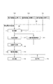
次に、放射線撮影システムの動作手順について図8のフローチャートを用いて説明する。 Next, the operation procedure of the radiography system will be described with reference to the flowchart of FIG.
ステップ(S801):操作者は、撮影台110に複数の放射線検出装置を配置する。操作者は、撮影台110には、放射線検出装置120、122、124を撮影台110の長手方向に沿ってそれぞれ配置する。このとき、操作者は、放射線を検出可能な有効画素領域が重なるように、放射線検出装置の一部を重ねながら複数の放射線検出装置を配置する。
Step (S801): The operator arranges a plurality of radiation detection devices on the photographing table 110. The operator arranges the
ステップ(S802):操作者は、複数の放射線検出装置120、122、124に対して同時に撮影を行わせ、複数の放射線検出装置120、122、124に対して同時に画像データを合成処理部142に出力させる。合成処理部142は、画像データを合成して長尺画像を生成する。
Step (S802): The operator causes a plurality of
ステップ(S803):操作者は、長尺画像に対して補正処理を行うかどうかについて、操作部134を介して選択する。例えば、放射線検出装置の構造物の写り込みが写り込んだ欠陥領域が診断領域から外れる場合、補正処理を行わなくてもよい。長尺画像の補正処理を行わない場合、ステップ(S805)に進む。長尺画像の補正処理を行なう場合、ステップ(S804)に進む。
Step (S803): The operator selects whether or not to perform correction processing on the long image via the
ステップ(S804):画像補正部146は、合成処理部142から出力された長尺画像に対して、放射線検出装置120及び放射線検出装置124の構造物の写り込みによる欠陥領域を低減させる処理を行う。
Step (S804): The
ステップ(S805):階調処理部148は、合成処理部142から出力された長尺画像に対して、階調処理を行なう。若しくは、階調処理部148は、画像補正部146によって補正が行われた長尺画像に対して、階調処理を行なう。
Step (S805): The
以上、本実施例によれば、放射線を検出する複数の放射線検出装置120、122、124と、複数の放射線検出装置から取得される複数の放射線画像を合成して長尺画像を生成する合成処理部142を有した放射線撮影システムにおいて、長尺画像における、放射線検出装置が重ね合わせられた領域の欠陥領域を補正する画像補正部146を備える。
As described above, according to the present embodiment, a synthesis process for generating a long image by synthesizing a plurality of
言い換えれば、一部が重なり合う複数の放射線検出部に同時に被検者を透過した放射線を照射して得られる複数の放射線画像を合成して長尺画像を生成する合成処理部142を有する放射線撮影システムにおいて、長尺画像における、放射線検出部の構造物が写り込んだ欠陥領域を補正する画像補正部146を備える。
In other words, a radiography system having a
欠陥領域の補正には放射線検出装置の写り込みに関する構造情報を用いる。これにより、欠陥領域を含んだ長尺画像の画質を向上させることができる。 Structural information regarding the reflection of the radiation detection device is used to correct the defective area. As a result, the image quality of a long image including a defective region can be improved.
次に実施例2について説明する。実施例1と異なる点は、合成処理部142は、放射線検出装置の配置関係に応じて、各画像データ(放射線画像)を調整して長尺画像を生成する点である。
Next, Example 2 will be described. The difference from the first embodiment is that the
具体的には、合成処理部142は、放射線検出装置の配置関係に応じて、各画像データの拡大率を調整して長尺画像を生成する。
Specifically, the
撮影台110には、放射線検出装置の一部を重ねながら複数の放射線検出装置が配置され、放射線発生部112に対する距離が異なるため、画像データ上の被検者の拡大率が異なる。具体的には、放射線発生部112からの距離が放射線検出装置120及び放射線検出装置124と比較して遠い放射線検出装置122で取得される画像データ上では被検者が拡大されて撮像される。そこで、合成処理部142は、放射線検出装置122で取得される画像データに合わせて、放射線検出装置120及び放射線検出装置124で取得される画像データを拡大する。
A plurality of radiation detection devices are arranged on the photographing table 110 while partially overlapping the radiation detection devices, and the distances to the
また、合成処理部142は、放射線検出装置122で取得される画像データに合わせて、放射線検出装置120及び放射線検出装置124で取得される画像データの相対位置を調整してもよい。撮影台への放射線検出装置の配置は、相対位置が一定となるように厳密に行うことは難しいため、数ミリの位置ずれが発生する可能性がある。そこで合成処理部142は、放射線検出装置120及び放射線検出装置124で取得され、拡大された画像データを、放射線検出装置122で取得される画像データに合わせた位置合わせを行い、合成することができる。
Further, the
なお、合成処理部142は、合成処理部142は、放射線検出装置122で取得される画像データに合わせて、放射線検出装置120及び放射線検出装置124で取得される画像データを回転してもよい。これも上述した撮影台への放射線検出装置の配置の際に生じる位置ずれに対応するものである。
The
以上の拡大率・相対位置・回転量は、重ね合わせられた領域における画像データ間の画像解析を行うことで求めることができる。例えば、拡大率・相対位置・回転量を所定範囲で微小に変動させながら重ね合わされた領域間の相関値を求め、相関値が最大になる拡大率・相対位置・回転量を求めればよい。 The above enlargement ratio, relative position, and rotation amount can be obtained by performing image analysis between image data in the superposed region. For example, the correlation value between the superposed regions may be obtained while slightly changing the enlargement ratio / relative position / rotation amount within a predetermined range, and the enlargement ratio / relative position / rotation amount that maximizes the correlation value may be obtained.
よって、本実施例によれば、合成処理部142は、複数の画像データを適切に合成して長尺画像を生成することができる。
Therefore, according to this embodiment, the
次に実施例3について、図9を用いて説明する。実施例1、2と異なる点は、画像データから放射線検出装置が重ね合わせられた領域における欠陥領域を取得する欠陥領域取得部144を有した点である。
Next, Example 3 will be described with reference to FIG. The difference from Examples 1 and 2 is that the radiation detection device has a defect
欠陥領域取得部144は、一方の放射線検出装置122から取得される画像データ(放射線画像)から他方の放射線検出装置120及び放射線検出装置124の構造物(構造情報)を示す欠陥領域を取得する。
The defect
具体的には、欠陥領域取得部144は、記憶部140から被検者100の画像情報が含まれていない放射線検出装置122の画像データを取得する。欠陥領域取得部144は、放射線検出装置122から取得される画像データのどの領域に放射線検出装置120及び放射線検出装置124の構造情報があるのかを認識する。つまり、欠陥領域取得部144は、放射線検出装置120及び放射線検出装置124の構造情報の領域情報を認識する。放射線検出装置120及び放射線検出装置124の構造情報の領域情報には、画像データにおける位置情報が含まれる。そして、欠陥領域取得部144は、欠陥領域を位置情報とともに画像補正部146に出力する。
Specifically, the defect
放射線検出装置120及び放射線検出装置124が、放射線検出装置122の一部と重なるように配置される場合、放射線検出装置120及び放射線検出装置124から取得される画像データから放射線検出装置122の欠陥領域を取得する。つまり、欠陥領域取得部144は、複数の放射線検出装置120、122、124の配置関係によって、どの放射線検出装置の画像データから欠陥領域を取得するのか決定する。ここでは、欠陥領域取得部144は、ある放射線検出装置よりも放射線発生部112に遠い側に配置された放射線検出装置から取得される画像データから放射線検出装置の欠陥領域を取得する。言い換えれば、欠陥領域取得部144は、ある放射線検出装置よりも放射線発生部112に近い側に配置された放射線検出装置から取得される画像データから放射線検出装置の欠陥領域を取得しない。
When the
欠陥領域取得部144は、放射線検出装置122から取得される画像データ302から欠陥領域を取得する。図4で示すような形態で複数の放射線検出装置120、122、124を配置して撮影した場合、放射線検出装置122は、放射線検出装置120及び放射線検出装置124の一部と重なるように配置される。そのため、放射線検出装置122から取得される画像データには、放射線検出装置120及び放射線検出装置124の構造情報が含まれている。欠陥領域取得部144は、放射線検出装置122から取得される画像データから放射線検出装置120及び放射線検出装置124の欠陥領域を取得する。
The defect
図9に示すように、画像補正部146は、合成処理部142から出力された長尺画像に対して、放射線検出装置120及び放射線検出装置124の構造情報における欠陥領域を低減させる処理を行う。つまり、画像補正部146は、放射線検出装置の一部(放射線検出装置の構造情報)が写り込んだ欠陥領域を補正する。
As shown in FIG. 9, the
具体的には、画像補正部146は、欠陥領域取得部144から出力された放射線検出装置120及び放射線検出装置124の構造情報の欠陥領域を認識し、合成画像に写り込まれた欠陥領域に対して補正を行う。画像補正部146は、放射線検出装置120及び放射線検出装置124の構造情報の周囲の画像情報から欠陥領域における画像情報を低減して、長尺画像を補正する。放射線検出装置120及び放射線検出装置124の構造情報の周囲の画像情報とは、正常な画像情報であり、構造情報が含まれていない画像情報である。このように、画像補正部146は、欠陥領域における画像欠陥を低減させ、長尺画像を補正することができる。
Specifically, the
100 被検者
110 撮影台
112 放射線発生部
114 照射範囲
120 放射線検出装置(D1)
122 放射線検出装置(D2)
124 放射線検出装置(D3)
130 画像表示制御部
132 表示部
134 操作部
140 記憶部
142 合成処理部
144 欠陥領域取得部
146 画像補正部
148 階調処理部
100 Subject 110 Shooting table 112
122 Radiation detector (D2)
124 Radiation detector (D3)
130 Image
Claims (32)
複数の放射線検出装置から取得される複数の放射線画像の拡大率を調整して合成することにより長尺画像を生成する合成処理部と、
一方の放射線検出装置から取得される放射線画像から他方の放射線検出装置の構造情報を示す欠陥領域を取得する欠陥領域取得部と、
前記長尺画像における、前記欠陥領域を補正する画像補正部と、
を備えることを特徴とする放射線撮影システム。 Multiple radiation detectors that detect radiation,
A synthesis processing unit that generates a long image by adjusting and synthesizing the magnification of multiple radiation images acquired from multiple radiation detectors, and
A defect area acquisition unit that acquires a defect area showing structural information of the other radiation detection device from a radiation image acquired from one radiation detection device, and a defect area acquisition unit.
In the elongated image, and an image correction section that corrects the defective area,
A radiography system characterized by being equipped with.
複数の放射線検出装置から取得される複数の放射線画像の拡大率を調整して合成することにより長尺画像を生成する合成処理部と、
前記長尺画像における、前記放射線検出装置の構造物が写り込んだ欠陥領域を補正する画像補正部と、
前記複数の放射線検出装置から出力される放射線画像を、被検者の画像情報が含まれた放射線画像であるのか、被検者の画像情報が含まれていない放射線画像であるのか区別して記憶する記憶部と、
を備えることを特徴とする放射線撮影システム。 Multiple radiation detectors that detect radiation,
A synthesis processing unit that generates a long image by adjusting and synthesizing the magnification of multiple radiation images acquired from multiple radiation detectors, and
An image correction unit that corrects a defect region in which the structure of the radiation detection device is reflected in the long image, and an image correction unit.
The radiation images output from the plurality of radiation detection devices are stored separately as to whether the radiation images include the image information of the subject or the radiation images that do not include the image information of the subject. Memory and
A radiography system characterized by being equipped with.
複数の放射線検出装置から取得される複数の放射線画像の拡大率を調整して合成することにより長尺画像を生成する合成処理部と、
前記長尺画像における、前記放射線検出装置の構造物が写り込んだ欠陥領域を補正する画像補正部と、を備え、
前記画像補正部は、前記欠陥領域を、前記欠陥領域に隣接する正常な画像領域の情報を利用して補正することを特徴とする放射線撮影システム。 Multiple radiation detectors that detect radiation,
A synthesis processing unit that generates a long image by adjusting and synthesizing the magnification of multiple radiation images acquired from multiple radiation detectors, and
An image correction unit for correcting a defect region in which a structure of the radiation detection device is reflected in the long image is provided.
The image correction unit is a radiography imaging system characterized in that the defect region is corrected by using information of a normal image region adjacent to the defect region.
複数の放射線検出装置から取得される複数の放射線画像の拡大率を調整して合成することにより長尺画像を生成する合成処理部と、
前記長尺画像における、前記放射線検出装置の構造物が写り込んだ欠陥領域を補正する画像補正部と、を備え、
前記画像補正部は、前記欠陥領域の欠陥行に対して、欠陥行に隣接する正常な画像領域を有した正常行を用いて補正することを特徴とする放射線撮影システム。 Multiple radiation detectors that detect radiation,
A synthesis processing unit that generates a long image by adjusting and synthesizing the magnification of multiple radiation images acquired from multiple radiation detectors, and
An image correction unit for correcting a defect region in which a structure of the radiation detection device is reflected in the long image is provided.
The image correction unit is a radiography system characterized in that a defective row in the defective region is corrected by using a normal row having a normal image region adjacent to the defective row.
複数の放射線検出装置から取得される複数の放射線画像の拡大率を調整して合成することにより長尺画像を生成する合成処理部と、
前記長尺画像における、前記放射線検出装置の構造物が写り込んだ欠陥領域を補正する画像補正部と、を備え、
前記画像補正部は、前記正常行の放射線画像を欠陥行の放射線画像とブレンドして、前記欠陥行を補正することを特徴とする請求項9に記載の放射線撮影システム。 Multiple radiation detectors that detect radiation,
A synthesis processing unit that generates a long image by adjusting and synthesizing the magnification of multiple radiation images acquired from multiple radiation detectors, and
An image correction unit for correcting a defect region in which a structure of the radiation detection device is reflected in the long image is provided.
The radiography system according to claim 9, wherein the image correction unit blends the radiation image of the normal line with the radiation image of the defect line to correct the defect line.
複数の放射線検出装置から取得される複数の放射線画像の拡大率を調整して合成することにより長尺画像を生成する合成処理部と、
前記長尺画像における、前記放射線検出装置の構造物が写り込んだ欠陥領域を補正する画像補正部と、を備え、
前記画像補正部は、前記欠陥領域を挟み込む、前記欠陥領域の隣接行から、双方向に補正を行うことで二つの補正結果を生成して前記長尺画像を補正することを特徴とする放射線撮影システム。 Multiple radiation detectors that detect radiation,
A synthesis processing unit that generates a long image by adjusting and synthesizing the magnification of multiple radiation images acquired from multiple radiation detectors, and
An image correction unit for correcting a defect region in which a structure of the radiation detection device is reflected in the long image is provided.
The image correction unit corrects the long image by generating two correction results by performing correction in both directions from adjacent lines of the defect region sandwiching the defect region. system.
複数の放射線検出装置から取得される複数の放射線画像の拡大率を調整して合成することにより長尺画像を生成する合成処理部と、
前記長尺画像における、前記放射線検出装置の構造物が写り込んだ欠陥領域を補正する画像補正部と、を備え、
前記合成処理部は、前記放射線検出装置の配置関係に基づいて、前記欠陥領域が前記長尺画像上で占める面積が最小となるように前記複数の放射線画像を合成することを特徴とする放射線撮影システム。 Multiple radiation detectors that detect radiation,
A synthesis processing unit that generates a long image by adjusting and synthesizing the magnification of multiple radiation images acquired from multiple radiation detectors, and
An image correction unit for correcting a defect region in which a structure of the radiation detection device is reflected in the long image is provided.
The synthesis processing unit synthesizes the plurality of radiographic images so that the area occupied by the defect region on the long image is minimized based on the arrangement relationship of the radiological detection apparatus. system.
一方の放射線検出装置から取得される放射線画像から他方の放射線検出装置の構造情報を示す欠陥領域を取得する欠陥領域取得部と、
前記長尺画像における、前記欠陥領域を補正する画像補正部と、を備えること
を特徴とする画像処理装置。 A compositing processing unit that generates a long image by adjusting the magnifying power of a plurality of radiation images obtained by simultaneously irradiating a plurality of overlapping radiation detectors with radiation transmitted through a subject and synthesizing them.
A defect area acquisition unit that acquires a defect area showing structural information of the other radiation detection device from a radiation image acquired from one radiation detection device, and a defect area acquisition unit.
An image processing apparatus including an image correction unit that corrects the defect region in the long image.
前記長尺画像における、前記放射線検出装置の構造物が写り込んだ欠陥領域を補正する画像補正部と、を備え、
前記画像補正部は、前記欠陥領域を、前記欠陥領域に隣接する正常な画像領域の情報を利用して補正することを特徴とする画像処理装置。 A compositing processing unit that generates a long image by adjusting the magnifying power of a plurality of radiation images obtained by simultaneously irradiating a plurality of overlapping radiation detectors with radiation transmitted through a subject and synthesizing them.
An image correction unit for correcting a defect region in which a structure of the radiation detection device is reflected in the long image is provided.
The image correction unit is an image processing apparatus characterized in that the defect region is corrected by using information of a normal image region adjacent to the defect region.
前記長尺画像における、前記放射線検出装置の構造物が写り込んだ欠陥領域を補正する画像補正部と、を備え、
前記画像補正部は、前記欠陥領域の欠陥行に対して、欠陥行に隣接する正常な画像領域を有した正常行を用いて補正することを特徴とする画像処理装置。 A compositing processing unit that generates a long image by adjusting the magnifying power of a plurality of radiation images obtained by simultaneously irradiating a plurality of overlapping radiation detectors with radiation transmitted through a subject and synthesizing them.
An image correction unit for correcting a defect region in which a structure of the radiation detection device is reflected in the long image is provided.
The image correction unit is an image processing apparatus characterized in that a defective row in the defective region is corrected by using a normal row having a normal image region adjacent to the defective row.
前記長尺画像における、前記放射線検出装置の構造物が写り込んだ欠陥領域を補正する画像補正部と、を備え、
前記画像補正部は、前記正常行の放射線画像を欠陥行の放射線画像と相関を取りながら欠陥行の放射線画像にブレンドして、前記欠陥行を補正することを特徴とする画像処理装置。 A compositing processing unit that generates a long image by adjusting the magnifying power of a plurality of radiation images obtained by simultaneously irradiating a plurality of overlapping radiation detectors with radiation transmitted through a subject and synthesizing them.
An image correction unit for correcting a defect region in which a structure of the radiation detection device is reflected in the long image is provided.
The image correction unit is an image processing apparatus characterized in that the radiation image of the normal row is blended with the radiation image of the defect row while correlating with the radiation image of the defect row to correct the defect row.
前記長尺画像における、前記放射線検出装置の構造物が写り込んだ欠陥領域を補正する画像補正部と、を備え、
前記画像補正部は、前記欠陥領域を挟み込む、前記欠陥領域の隣接行から、双方向に補正を行うことで二つの補正結果を生成して前記長尺画像を補正することを特徴とする画像処理装置。 A compositing processing unit that generates a long image by adjusting the magnifying power of a plurality of radiation images obtained by simultaneously irradiating a plurality of overlapping radiation detectors with radiation transmitted through a subject and synthesizing them.
An image correction unit for correcting a defect region in which a structure of the radiation detection device is reflected in the long image is provided.
The image correction unit is characterized in that it corrects the long image by generating two correction results by performing correction in both directions from adjacent lines of the defect area sandwiching the defect area. apparatus.
一方の放射線検出装置から取得される放射線画像から他方の放射線検出装置の構造情報を示す欠陥領域を取得するステップと、
前記長尺画像における、前記欠陥領域を補正するステップと、を有すること
を特徴とする画像処理方法。 A step of adjusting and synthesizing a plurality of radiation images obtained by irradiating a plurality of radiation detectors having partially overlapped with radiation transmitted through a subject at the same time.
A step of acquiring a defect region showing structural information of the other radiation detector from a radiation image acquired from one radiation detector, and
An image processing method comprising: a step of correcting the defect region in the long image.
前記長尺画像における、前記放射線検出装置の構造物が写り込んだ欠陥領域を補正するステップと、を有し、
前記補正するステップにおいて、前記欠陥領域を、前記欠陥領域に隣接する正常な画像領域の情報を利用して補正することを特徴とする画像処理方法。 A step of adjusting and synthesizing a plurality of radiation images obtained by irradiating a plurality of radiation detectors having partially overlapped with radiation transmitted through a subject at the same time.
It has a step of correcting a defect region in which the structure of the radiation detection device is reflected in the long image.
An image processing method characterized in that, in the correction step, the defect region is corrected by using information of a normal image region adjacent to the defect region.
前記長尺画像における、前記放射線検出装置の構造物が写り込んだ欠陥領域を補正するステップと、を有し、
前記補正するステップにおいて、前記欠陥領域の欠陥行に対して、欠陥行に隣接する正常な画像領域を有した正常行を用いて補正することを特徴とする画像処理方法。 A step of adjusting and synthesizing a plurality of radiation images obtained by irradiating a plurality of radiation detectors having partially overlapped with radiation transmitted through a subject at the same time.
It has a step of correcting a defect region in which the structure of the radiation detection device is reflected in the long image.
An image processing method, characterized in that, in the correction step, a defective row in the defective region is corrected by using a normal row having a normal image region adjacent to the defective row.
前記長尺画像における、前記放射線検出装置の構造物が写り込んだ欠陥領域を補正するステップと、を有し、
前記画像補正部は、前記欠陥領域を挟み込む、前記欠陥領域の隣接行から、双方向に補正を行うことで二つの補正結果を生成して前記長尺画像を補正することを特徴とする画像処理方法。 A step of adjusting and synthesizing a plurality of radiation images obtained by irradiating a plurality of radiation detectors having partially overlapped with radiation transmitted through a subject at the same time.
It has a step of correcting a defect region in which the structure of the radiation detection device is reflected in the long image.
The image correction unit is characterized in that it corrects the long image by generating two correction results by performing correction in both directions from adjacent lines of the defect area sandwiching the defect area. Method.
Priority Applications (1)
| Application Number | Priority Date | Filing Date | Title |
|---|---|---|---|
| JP2019119134A JP6780065B2 (en) | 2019-06-26 | 2019-06-26 | Radiation imaging system and radiography imaging method |
Applications Claiming Priority (1)
| Application Number | Priority Date | Filing Date | Title |
|---|---|---|---|
| JP2019119134A JP6780065B2 (en) | 2019-06-26 | 2019-06-26 | Radiation imaging system and radiography imaging method |
Related Parent Applications (1)
| Application Number | Title | Priority Date | Filing Date |
|---|---|---|---|
| JP2016251181A Division JP6548628B2 (en) | 2016-12-26 | 2016-12-26 | Radiography system and radiography method |
Publications (3)
| Publication Number | Publication Date |
|---|---|
| JP2019155163A JP2019155163A (en) | 2019-09-19 |
| JP2019155163A5 JP2019155163A5 (en) | 2020-04-16 |
| JP6780065B2 true JP6780065B2 (en) | 2020-11-04 |
Family
ID=67994156
Family Applications (1)
| Application Number | Title | Priority Date | Filing Date |
|---|---|---|---|
| JP2019119134A Active JP6780065B2 (en) | 2019-06-26 | 2019-06-26 | Radiation imaging system and radiography imaging method |
Country Status (1)
| Country | Link |
|---|---|
| JP (1) | JP6780065B2 (en) |
Family Cites Families (4)
| Publication number | Priority date | Publication date | Assignee | Title |
|---|---|---|---|---|
| JP2000278607A (en) * | 1999-03-29 | 2000-10-06 | Matsushita Electric Ind Co Ltd | X-ray photographing device |
| JP5402576B2 (en) * | 2009-11-27 | 2014-01-29 | 株式会社島津製作所 | X-ray imaging apparatus and X-ray imaging method |
| JP5480117B2 (en) * | 2010-03-29 | 2014-04-23 | 富士フイルム株式会社 | Radiation image capturing apparatus and radiation image capturing system |
| JP2012161472A (en) * | 2011-02-07 | 2012-08-30 | Fujifilm Corp | Radiographic imaging apparatus and method of radiographic imaging |
-
2019
- 2019-06-26 JP JP2019119134A patent/JP6780065B2/en active Active
Also Published As
| Publication number | Publication date |
|---|---|
| JP2019155163A (en) | 2019-09-19 |
Similar Documents
| Publication | Publication Date | Title |
|---|---|---|
| JP6072102B2 (en) | Radiographic system and radiographic method | |
| JP6862099B2 (en) | Radiation imaging system and radiography imaging method | |
| JP6815818B2 (en) | Radiation imaging system and radiography imaging method | |
| US7555100B2 (en) | Long length imaging using digital radiography | |
| JP6525680B2 (en) | Radiography system, control method and program | |
| JP6957170B2 (en) | Radiation imaging equipment, radiography systems, radiography methods, and programs | |
| JP2012075862A (en) | Body motion detector, method, and program | |
| JP6676345B2 (en) | Radiation imaging system and radiation imaging method | |
| JP2005204810A (en) | X-ray imaging apparatus | |
| JP7091047B2 (en) | Radiation imaging system and radiography imaging method | |
| JP6780065B2 (en) | Radiation imaging system and radiography imaging method | |
| JP6548628B2 (en) | Radiography system and radiography method | |
| WO2018135287A1 (en) | Radiographic image capturing system and radiographic image capturing method | |
| JP2017169715A (en) | Image processing device, radiographic image capturing system, image processing method, and image processing program | |
| JP2017077405A (en) | Radiographic system, image processing device, and image processing method | |
| JP5562184B2 (en) | Radiation imaging apparatus, method and program | |
| JP2016138757A (en) | Device and method for measuring radiation | |
| JP2019107065A (en) | Image processing device, radiographic system, image processing method, and program | |
| JP7115545B2 (en) | Medical X-ray image processing device and X-ray imaging device | |
| JP2012055474A (en) | Body motion detection device, method and program | |
| JP2005066144A (en) | X-ray imaging apparatus | |
| JP2019208824A (en) | Image processing device, image processing method, and program |
Legal Events
| Date | Code | Title | Description |
|---|---|---|---|
| A621 | Written request for application examination |
Free format text: JAPANESE INTERMEDIATE CODE: A621 Effective date: 20190725 |
|
| A521 | Request for written amendment filed |
Free format text: JAPANESE INTERMEDIATE CODE: A523 Effective date: 20200309 |
|
| A131 | Notification of reasons for refusal |
Free format text: JAPANESE INTERMEDIATE CODE: A131 Effective date: 20200428 |
|
| A521 | Request for written amendment filed |
Free format text: JAPANESE INTERMEDIATE CODE: A523 Effective date: 20200626 |
|
| TRDD | Decision of grant or rejection written | ||
| A01 | Written decision to grant a patent or to grant a registration (utility model) |
Free format text: JAPANESE INTERMEDIATE CODE: A01 Effective date: 20200915 |
|
| A61 | First payment of annual fees (during grant procedure) |
Free format text: JAPANESE INTERMEDIATE CODE: A61 Effective date: 20201014 |
|
| R151 | Written notification of patent or utility model registration |
Ref document number: 6780065 Country of ref document: JP Free format text: JAPANESE INTERMEDIATE CODE: R151 |
|
| S802 | Written request for registration of partial abandonment of right |
Free format text: JAPANESE INTERMEDIATE CODE: R311802 |
|
| R350 | Written notification of registration of transfer |
Free format text: JAPANESE INTERMEDIATE CODE: R350 |