JP6779902B2 - How to apply a support to a surgical stapler - Google Patents
How to apply a support to a surgical stapler Download PDFInfo
- Publication number
- JP6779902B2 JP6779902B2 JP2017549692A JP2017549692A JP6779902B2 JP 6779902 B2 JP6779902 B2 JP 6779902B2 JP 2017549692 A JP2017549692 A JP 2017549692A JP 2017549692 A JP2017549692 A JP 2017549692A JP 6779902 B2 JP6779902 B2 JP 6779902B2
- Authority
- JP
- Japan
- Prior art keywords
- adhesive
- anvil
- staple cartridge
- support
- support assembly
- Prior art date
- Legal status (The legal status is an assumption and is not a legal conclusion. Google has not performed a legal analysis and makes no representation as to the accuracy of the status listed.)
- Active
Links
- 230000001070 adhesive effect Effects 0.000 claims description 517
- 239000000853 adhesive Substances 0.000 claims description 515
- 239000012636 effector Substances 0.000 claims description 177
- 238000000034 method Methods 0.000 claims description 118
- 229920000642 polymer Polymers 0.000 claims description 104
- 229920001577 copolymer Polymers 0.000 claims description 90
- PAPBSGBWRJIAAV-UHFFFAOYSA-N ε-Caprolactone Chemical compound O=C1CCCCCO1 PAPBSGBWRJIAAV-UHFFFAOYSA-N 0.000 claims description 58
- 230000009477 glass transition Effects 0.000 claims description 35
- 230000003014 reinforcing effect Effects 0.000 claims description 29
- RKDVKSZUMVYZHH-UHFFFAOYSA-N 1,4-dioxane-2,5-dione Chemical compound O=C1COC(=O)CO1 RKDVKSZUMVYZHH-UHFFFAOYSA-N 0.000 claims description 25
- 230000002745 absorbent Effects 0.000 claims description 23
- 239000002250 absorbent Substances 0.000 claims description 23
- JJTUDXZGHPGLLC-UHFFFAOYSA-N lactide Chemical compound CC1OC(=O)C(C)OC1=O JJTUDXZGHPGLLC-UHFFFAOYSA-N 0.000 claims description 23
- YFHICDDUDORKJB-UHFFFAOYSA-N trimethylene carbonate Chemical compound O=C1OCCCO1 YFHICDDUDORKJB-UHFFFAOYSA-N 0.000 claims description 23
- 230000008569 process Effects 0.000 claims description 21
- 238000002347 injection Methods 0.000 claims description 19
- 239000007924 injection Substances 0.000 claims description 19
- 230000000712 assembly Effects 0.000 claims description 11
- 238000000429 assembly Methods 0.000 claims description 11
- 229920001245 poly(D,L-lactide-co-caprolactone) Polymers 0.000 claims description 11
- 230000009471 action Effects 0.000 claims description 7
- 238000003825 pressing Methods 0.000 claims description 5
- 238000000926 separation method Methods 0.000 claims 1
- 239000000203 mixture Substances 0.000 description 99
- 239000012530 fluid Substances 0.000 description 94
- 239000010410 layer Substances 0.000 description 93
- 210000001519 tissue Anatomy 0.000 description 91
- 239000012790 adhesive layer Substances 0.000 description 82
- 239000000463 material Substances 0.000 description 75
- 239000000499 gel Substances 0.000 description 49
- 229920001223 polyethylene glycol Polymers 0.000 description 49
- 239000002202 Polyethylene glycol Substances 0.000 description 47
- 239000010408 film Substances 0.000 description 41
- 230000033001 locomotion Effects 0.000 description 29
- 230000007246 mechanism Effects 0.000 description 29
- 239000007788 liquid Substances 0.000 description 27
- 238000001356 surgical procedure Methods 0.000 description 27
- 238000010304 firing Methods 0.000 description 26
- 238000000465 moulding Methods 0.000 description 26
- PEDCQBHIVMGVHV-UHFFFAOYSA-N Glycerine Chemical compound OCC(O)CO PEDCQBHIVMGVHV-UHFFFAOYSA-N 0.000 description 24
- 239000002313 adhesive film Substances 0.000 description 20
- 238000005520 cutting process Methods 0.000 description 20
- -1 hemostasis Proteins 0.000 description 19
- 239000000017 hydrogel Substances 0.000 description 19
- 235000010409 propane-1,2-diol alginate Nutrition 0.000 description 19
- 229920000954 Polyglycolide Polymers 0.000 description 18
- 239000007787 solid Substances 0.000 description 18
- 229920001059 synthetic polymer Polymers 0.000 description 16
- 239000004820 Pressure-sensitive adhesive Substances 0.000 description 15
- 239000006260 foam Substances 0.000 description 15
- 238000002844 melting Methods 0.000 description 15
- 230000008018 melting Effects 0.000 description 15
- 229920005615 natural polymer Polymers 0.000 description 15
- 210000004027 cell Anatomy 0.000 description 14
- 229920001343 polytetrafluoroethylene Polymers 0.000 description 14
- 239000004810 polytetrafluoroethylene Substances 0.000 description 14
- 229920002463 poly(p-dioxanone) polymer Polymers 0.000 description 12
- 230000000694 effects Effects 0.000 description 11
- 239000000622 polydioxanone Substances 0.000 description 11
- LCSKNASZPVZHEG-UHFFFAOYSA-N 3,6-dimethyl-1,4-dioxane-2,5-dione;1,4-dioxane-2,5-dione Chemical compound O=C1COC(=O)CO1.CC1OC(=O)C(C)OC1=O LCSKNASZPVZHEG-UHFFFAOYSA-N 0.000 description 10
- 235000011187 glycerol Nutrition 0.000 description 10
- 230000004048 modification Effects 0.000 description 10
- 238000012986 modification Methods 0.000 description 10
- 239000000243 solution Substances 0.000 description 10
- XLYOFNOQVPJJNP-UHFFFAOYSA-N water Substances O XLYOFNOQVPJJNP-UHFFFAOYSA-N 0.000 description 10
- 239000012141 concentrate Substances 0.000 description 9
- 102000010834 Extracellular Matrix Proteins Human genes 0.000 description 8
- 108010037362 Extracellular Matrix Proteins Proteins 0.000 description 8
- 229920002678 cellulose Polymers 0.000 description 8
- 239000001913 cellulose Substances 0.000 description 8
- 230000000295 complement effect Effects 0.000 description 8
- 230000006835 compression Effects 0.000 description 8
- 238000007906 compression Methods 0.000 description 8
- 210000002744 extracellular matrix Anatomy 0.000 description 8
- 238000010438 heat treatment Methods 0.000 description 8
- 229920002101 Chitin Polymers 0.000 description 7
- 239000000835 fiber Substances 0.000 description 7
- 239000000178 monomer Substances 0.000 description 7
- AEMRFAOFKBGASW-UHFFFAOYSA-N Glycolic acid Chemical compound OCC(O)=O AEMRFAOFKBGASW-UHFFFAOYSA-N 0.000 description 6
- 230000015572 biosynthetic process Effects 0.000 description 6
- 229920001400 block copolymer Polymers 0.000 description 6
- 239000008280 blood Substances 0.000 description 6
- 210000004369 blood Anatomy 0.000 description 6
- 150000001875 compounds Chemical class 0.000 description 6
- 230000002439 hemostatic effect Effects 0.000 description 6
- JVTAAEKCZFNVCJ-UHFFFAOYSA-N lactic acid Chemical compound CC(O)C(O)=O JVTAAEKCZFNVCJ-UHFFFAOYSA-N 0.000 description 6
- 150000002596 lactones Chemical class 0.000 description 6
- 229920001282 polysaccharide Polymers 0.000 description 6
- 239000005017 polysaccharide Substances 0.000 description 6
- 150000004804 polysaccharides Chemical class 0.000 description 6
- 229920002635 polyurethane Polymers 0.000 description 6
- 239000004814 polyurethane Substances 0.000 description 6
- 108090000623 proteins and genes Proteins 0.000 description 6
- 239000004627 regenerated cellulose Substances 0.000 description 6
- 230000002787 reinforcement Effects 0.000 description 6
- 230000004044 response Effects 0.000 description 6
- 229920002134 Carboxymethyl cellulose Polymers 0.000 description 5
- 229920001661 Chitosan Polymers 0.000 description 5
- 102000009123 Fibrin Human genes 0.000 description 5
- 108010073385 Fibrin Proteins 0.000 description 5
- BWGVNKXGVNDBDI-UHFFFAOYSA-N Fibrin monomer Chemical compound CNC(=O)CNC(=O)CN BWGVNKXGVNDBDI-UHFFFAOYSA-N 0.000 description 5
- 108090000190 Thrombin Proteins 0.000 description 5
- 239000000654 additive Substances 0.000 description 5
- 229940030225 antihemorrhagics Drugs 0.000 description 5
- 238000004140 cleaning Methods 0.000 description 5
- 229950003499 fibrin Drugs 0.000 description 5
- 238000011049 filling Methods 0.000 description 5
- 239000002874 hemostatic agent Substances 0.000 description 5
- 230000002209 hydrophobic effect Effects 0.000 description 5
- 230000036961 partial effect Effects 0.000 description 5
- 102000004169 proteins and genes Human genes 0.000 description 5
- 239000000126 substance Substances 0.000 description 5
- 229920001897 terpolymer Polymers 0.000 description 5
- 229960004072 thrombin Drugs 0.000 description 5
- KIUKXJAPPMFGSW-DNGZLQJQSA-N (2S,3S,4S,5R,6R)-6-[(2S,3R,4R,5S,6R)-3-Acetamido-2-[(2S,3S,4R,5R,6R)-6-[(2R,3R,4R,5S,6R)-3-acetamido-2,5-dihydroxy-6-(hydroxymethyl)oxan-4-yl]oxy-2-carboxy-4,5-dihydroxyoxan-3-yl]oxy-5-hydroxy-6-(hydroxymethyl)oxan-4-yl]oxy-3,4,5-trihydroxyoxane-2-carboxylic acid Chemical compound CC(=O)N[C@H]1[C@H](O)O[C@H](CO)[C@@H](O)[C@@H]1O[C@H]1[C@H](O)[C@@H](O)[C@H](O[C@H]2[C@@H]([C@@H](O[C@H]3[C@@H]([C@@H](O)[C@H](O)[C@H](O3)C(O)=O)O)[C@H](O)[C@@H](CO)O2)NC(C)=O)[C@@H](C(O)=O)O1 KIUKXJAPPMFGSW-DNGZLQJQSA-N 0.000 description 4
- BYEAHWXPCBROCE-UHFFFAOYSA-N 1,1,1,3,3,3-hexafluoropropan-2-ol Chemical compound FC(F)(F)C(O)C(F)(F)F BYEAHWXPCBROCE-UHFFFAOYSA-N 0.000 description 4
- VPVXHAANQNHFSF-UHFFFAOYSA-N 1,4-dioxan-2-one Chemical group O=C1COCCO1 VPVXHAANQNHFSF-UHFFFAOYSA-N 0.000 description 4
- 102000008186 Collagen Human genes 0.000 description 4
- 108010035532 Collagen Proteins 0.000 description 4
- 239000002253 acid Substances 0.000 description 4
- 230000000740 bleeding effect Effects 0.000 description 4
- 239000003054 catalyst Substances 0.000 description 4
- 230000008859 change Effects 0.000 description 4
- 238000006243 chemical reaction Methods 0.000 description 4
- 229920001436 collagen Polymers 0.000 description 4
- 238000004132 cross linking Methods 0.000 description 4
- 238000009826 distribution Methods 0.000 description 4
- RTZKZFJDLAIYFH-UHFFFAOYSA-N ether Substances CCOCC RTZKZFJDLAIYFH-UHFFFAOYSA-N 0.000 description 4
- 239000004744 fabric Substances 0.000 description 4
- 229920001519 homopolymer Polymers 0.000 description 4
- 210000000056 organ Anatomy 0.000 description 4
- 238000003860 storage Methods 0.000 description 4
- 229920002818 (Hydroxyethyl)methacrylate Polymers 0.000 description 3
- IAYPIBMASNFSPL-UHFFFAOYSA-N Ethylene oxide Chemical compound C1CO1 IAYPIBMASNFSPL-UHFFFAOYSA-N 0.000 description 3
- 108010010803 Gelatin Proteins 0.000 description 3
- 229920002971 Heparan sulfate Polymers 0.000 description 3
- WOBHKFSMXKNTIM-UHFFFAOYSA-N Hydroxyethyl methacrylate Chemical compound CC(=C)C(=O)OCCO WOBHKFSMXKNTIM-UHFFFAOYSA-N 0.000 description 3
- QAOWNCQODCNURD-UHFFFAOYSA-L Sulfate Chemical compound [O-]S([O-])(=O)=O QAOWNCQODCNURD-UHFFFAOYSA-L 0.000 description 3
- 229920006125 amorphous polymer Polymers 0.000 description 3
- 210000004204 blood vessel Anatomy 0.000 description 3
- 239000001768 carboxy methyl cellulose Substances 0.000 description 3
- 235000010948 carboxy methyl cellulose Nutrition 0.000 description 3
- 239000008112 carboxymethyl-cellulose Substances 0.000 description 3
- 230000015556 catabolic process Effects 0.000 description 3
- 238000000576 coating method Methods 0.000 description 3
- 238000006731 degradation reaction Methods 0.000 description 3
- MTHSVFCYNBDYFN-UHFFFAOYSA-N diethylene glycol Chemical compound OCCOCCO MTHSVFCYNBDYFN-UHFFFAOYSA-N 0.000 description 3
- 239000007789 gas Substances 0.000 description 3
- 239000008273 gelatin Substances 0.000 description 3
- 229920000159 gelatin Polymers 0.000 description 3
- 235000019322 gelatine Nutrition 0.000 description 3
- 235000011852 gelatine desserts Nutrition 0.000 description 3
- 230000014509 gene expression Effects 0.000 description 3
- 229920002674 hyaluronan Polymers 0.000 description 3
- 229960003160 hyaluronic acid Drugs 0.000 description 3
- 239000003999 initiator Substances 0.000 description 3
- 238000009434 installation Methods 0.000 description 3
- 230000003993 interaction Effects 0.000 description 3
- 230000014759 maintenance of location Effects 0.000 description 3
- 239000011159 matrix material Substances 0.000 description 3
- 229920003023 plastic Polymers 0.000 description 3
- 239000004033 plastic Substances 0.000 description 3
- 239000004014 plasticizer Substances 0.000 description 3
- 229920005862 polyol Polymers 0.000 description 3
- 150000003077 polyols Chemical class 0.000 description 3
- 150000003839 salts Chemical class 0.000 description 3
- 238000007789 sealing Methods 0.000 description 3
- 239000000758 substrate Substances 0.000 description 3
- 239000010409 thin film Substances 0.000 description 3
- 230000007704 transition Effects 0.000 description 3
- SJDLIJNQXLJBBE-UHFFFAOYSA-N 1,4-dioxepan-2-one Chemical compound O=C1COCCCO1 SJDLIJNQXLJBBE-UHFFFAOYSA-N 0.000 description 2
- 239000004970 Chain extender Substances 0.000 description 2
- 102100022641 Coagulation factor IX Human genes 0.000 description 2
- 229920002307 Dextran Polymers 0.000 description 2
- 108010076282 Factor IX Proteins 0.000 description 2
- 229920002527 Glycogen Polymers 0.000 description 2
- HTTJABKRGRZYRN-UHFFFAOYSA-N Heparin Chemical compound OC1C(NC(=O)C)C(O)OC(COS(O)(=O)=O)C1OC1C(OS(O)(=O)=O)C(O)C(OC2C(C(OS(O)(=O)=O)C(OC3C(C(O)C(O)C(O3)C(O)=O)OS(O)(=O)=O)C(CO)O2)NS(O)(=O)=O)C(C(O)=O)O1 HTTJABKRGRZYRN-UHFFFAOYSA-N 0.000 description 2
- 206010061218 Inflammation Diseases 0.000 description 2
- 239000004264 Petrolatum Substances 0.000 description 2
- 229920003171 Poly (ethylene oxide) Polymers 0.000 description 2
- 229920002565 Polyethylene Glycol 400 Polymers 0.000 description 2
- 229920002472 Starch Polymers 0.000 description 2
- ATJFFYVFTNAWJD-UHFFFAOYSA-N Tin Chemical group [Sn] ATJFFYVFTNAWJD-UHFFFAOYSA-N 0.000 description 2
- 238000010521 absorption reaction Methods 0.000 description 2
- 150000001252 acrylic acid derivatives Chemical class 0.000 description 2
- 235000010443 alginic acid Nutrition 0.000 description 2
- 229920000615 alginic acid Polymers 0.000 description 2
- 229920003232 aliphatic polyester Polymers 0.000 description 2
- 235000013871 bee wax Nutrition 0.000 description 2
- 239000012166 beeswax Substances 0.000 description 2
- 230000000903 blocking effect Effects 0.000 description 2
- 229920003064 carboxyethyl cellulose Polymers 0.000 description 2
- 150000001735 carboxylic acids Chemical class 0.000 description 2
- 125000002057 carboxymethyl group Chemical group [H]OC(=O)C([H])([H])[*] 0.000 description 2
- 229940045110 chitosan Drugs 0.000 description 2
- 239000011248 coating agent Substances 0.000 description 2
- 238000004891 communication Methods 0.000 description 2
- 238000001816 cooling Methods 0.000 description 2
- 230000008878 coupling Effects 0.000 description 2
- 238000010168 coupling process Methods 0.000 description 2
- 238000005859 coupling reaction Methods 0.000 description 2
- 229960002086 dextran Drugs 0.000 description 2
- LQZZUXJYWNFBMV-UHFFFAOYSA-N dodecan-1-ol Chemical compound CCCCCCCCCCCCO LQZZUXJYWNFBMV-UHFFFAOYSA-N 0.000 description 2
- 239000003814 drug Substances 0.000 description 2
- 229920001971 elastomer Polymers 0.000 description 2
- 239000000806 elastomer Substances 0.000 description 2
- 238000002674 endoscopic surgery Methods 0.000 description 2
- 229960004222 factor ix Drugs 0.000 description 2
- 239000010419 fine particle Substances 0.000 description 2
- 239000006261 foam material Substances 0.000 description 2
- 229940096919 glycogen Drugs 0.000 description 2
- 239000001257 hydrogen Substances 0.000 description 2
- 229910052739 hydrogen Inorganic materials 0.000 description 2
- 229920013821 hydroxy alkyl cellulose Polymers 0.000 description 2
- 230000004054 inflammatory process Effects 0.000 description 2
- 230000001788 irregular Effects 0.000 description 2
- 239000012948 isocyanate Substances 0.000 description 2
- 150000002513 isocyanates Chemical class 0.000 description 2
- XUGNVMKQXJXZCD-UHFFFAOYSA-N isopropyl palmitate Chemical compound CCCCCCCCCCCCCCCC(=O)OC(C)C XUGNVMKQXJXZCD-UHFFFAOYSA-N 0.000 description 2
- 235000014655 lactic acid Nutrition 0.000 description 2
- 239000004310 lactic acid Substances 0.000 description 2
- 230000000670 limiting effect Effects 0.000 description 2
- 238000004519 manufacturing process Methods 0.000 description 2
- 238000002156 mixing Methods 0.000 description 2
- DNIAPMSPPWPWGF-UHFFFAOYSA-N monopropylene glycol Natural products CC(O)CO DNIAPMSPPWPWGF-UHFFFAOYSA-N 0.000 description 2
- 125000002524 organometallic group Chemical group 0.000 description 2
- 239000001814 pectin Substances 0.000 description 2
- 235000010987 pectin Nutrition 0.000 description 2
- 229920001277 pectin Polymers 0.000 description 2
- 229940066842 petrolatum Drugs 0.000 description 2
- 235000019271 petrolatum Nutrition 0.000 description 2
- 229920000117 poly(dioxanone) Polymers 0.000 description 2
- 238000006116 polymerization reaction Methods 0.000 description 2
- 229920006124 polyolefin elastomer Polymers 0.000 description 2
- 229920001451 polypropylene glycol Polymers 0.000 description 2
- 229920000166 polytrimethylene carbonate Polymers 0.000 description 2
- ULWHHBHJGPPBCO-UHFFFAOYSA-N propane-1,1-diol Chemical compound CCC(O)O ULWHHBHJGPPBCO-UHFFFAOYSA-N 0.000 description 2
- 239000011241 protective layer Substances 0.000 description 2
- 230000005855 radiation Effects 0.000 description 2
- 238000007151 ring opening polymerisation reaction Methods 0.000 description 2
- 239000008159 sesame oil Substances 0.000 description 2
- 235000011803 sesame oil Nutrition 0.000 description 2
- 239000002904 solvent Substances 0.000 description 2
- 239000008107 starch Substances 0.000 description 2
- 235000019698 starch Nutrition 0.000 description 2
- 238000003756 stirring Methods 0.000 description 2
- 239000000725 suspension Substances 0.000 description 2
- 239000003356 suture material Substances 0.000 description 2
- 230000001225 therapeutic effect Effects 0.000 description 2
- 238000002560 therapeutic procedure Methods 0.000 description 2
- 210000000115 thoracic cavity Anatomy 0.000 description 2
- 210000003813 thumb Anatomy 0.000 description 2
- 238000013519 translation Methods 0.000 description 2
- 239000001993 wax Substances 0.000 description 2
- DNIAPMSPPWPWGF-VKHMYHEASA-N (+)-propylene glycol Chemical compound C[C@H](O)CO DNIAPMSPPWPWGF-VKHMYHEASA-N 0.000 description 1
- DNIAPMSPPWPWGF-GSVOUGTGSA-N (R)-(-)-Propylene glycol Chemical compound C[C@@H](O)CO DNIAPMSPPWPWGF-GSVOUGTGSA-N 0.000 description 1
- UCTWMZQNUQWSLP-VIFPVBQESA-N (R)-adrenaline Chemical compound CNC[C@H](O)C1=CC=C(O)C(O)=C1 UCTWMZQNUQWSLP-VIFPVBQESA-N 0.000 description 1
- 229930182837 (R)-adrenaline Natural products 0.000 description 1
- UJGHGRGFKZWGMS-UHFFFAOYSA-N 1,3-dioxan-2-one Chemical compound O=C1OCCCO1.O=C1OCCCO1 UJGHGRGFKZWGMS-UHFFFAOYSA-N 0.000 description 1
- YPFDHNVEDLHUCE-UHFFFAOYSA-N 1,3-propanediol Substances OCCCO YPFDHNVEDLHUCE-UHFFFAOYSA-N 0.000 description 1
- KSYBWAGMCCOKQE-UHFFFAOYSA-N 1,4-dioxane;1,4-dioxan-2-one Chemical compound C1COCCO1.O=C1COCCO1 KSYBWAGMCCOKQE-UHFFFAOYSA-N 0.000 description 1
- AOLNDUQWRUPYGE-UHFFFAOYSA-N 1,4-dioxepan-5-one Chemical group O=C1CCOCCO1 AOLNDUQWRUPYGE-UHFFFAOYSA-N 0.000 description 1
- IXPNQXFRVYWDDI-UHFFFAOYSA-N 1-methyl-2,4-dioxo-1,3-diazinane-5-carboximidamide Chemical compound CN1CC(C(N)=N)C(=O)NC1=O IXPNQXFRVYWDDI-UHFFFAOYSA-N 0.000 description 1
- FHVDTGUDJYJELY-UHFFFAOYSA-N 6-{[2-carboxy-4,5-dihydroxy-6-(phosphanyloxy)oxan-3-yl]oxy}-4,5-dihydroxy-3-phosphanyloxane-2-carboxylic acid Chemical compound O1C(C(O)=O)C(P)C(O)C(O)C1OC1C(C(O)=O)OC(OP)C(O)C1O FHVDTGUDJYJELY-UHFFFAOYSA-N 0.000 description 1
- 102000009027 Albumins Human genes 0.000 description 1
- 108010088751 Albumins Proteins 0.000 description 1
- 229920000945 Amylopectin Polymers 0.000 description 1
- 229920000856 Amylose Polymers 0.000 description 1
- 241000894006 Bacteria Species 0.000 description 1
- 206010051542 Bone fistula Diseases 0.000 description 1
- BVKZGUZCCUSVTD-UHFFFAOYSA-L Carbonate Chemical compound [O-]C([O-])=O BVKZGUZCCUSVTD-UHFFFAOYSA-L 0.000 description 1
- 229920002567 Chondroitin Polymers 0.000 description 1
- 229920001287 Chondroitin sulfate Polymers 0.000 description 1
- 102100023804 Coagulation factor VII Human genes 0.000 description 1
- 102000016942 Elastin Human genes 0.000 description 1
- 108010014258 Elastin Proteins 0.000 description 1
- 108010048049 Factor IXa Proteins 0.000 description 1
- 108010023321 Factor VII Proteins 0.000 description 1
- 108010054265 Factor VIIa Proteins 0.000 description 1
- 108010074864 Factor XI Proteins 0.000 description 1
- 108010080865 Factor XII Proteins 0.000 description 1
- 102000000429 Factor XII Human genes 0.000 description 1
- 108010071241 Factor XIIa Proteins 0.000 description 1
- 108010080805 Factor XIa Proteins 0.000 description 1
- 108010074860 Factor Xa Proteins 0.000 description 1
- 108010049003 Fibrinogen Proteins 0.000 description 1
- 102000008946 Fibrinogen Human genes 0.000 description 1
- 102000016359 Fibronectins Human genes 0.000 description 1
- 108010067306 Fibronectins Proteins 0.000 description 1
- WQZGKKKJIJFFOK-GASJEMHNSA-N Glucose Natural products OC[C@H]1OC(O)[C@H](O)[C@@H](O)[C@@H]1O WQZGKKKJIJFFOK-GASJEMHNSA-N 0.000 description 1
- 239000004705 High-molecular-weight polyethylene Substances 0.000 description 1
- UFHFLCQGNIYNRP-UHFFFAOYSA-N Hydrogen Chemical compound [H][H] UFHFLCQGNIYNRP-UHFFFAOYSA-N 0.000 description 1
- 229920000663 Hydroxyethyl cellulose Polymers 0.000 description 1
- 239000004354 Hydroxyethyl cellulose Substances 0.000 description 1
- 229920002153 Hydroxypropyl cellulose Polymers 0.000 description 1
- 229920002201 Oxidized cellulose Polymers 0.000 description 1
- 108010001014 Plasminogen Activators Proteins 0.000 description 1
- 102000001938 Plasminogen Activators Human genes 0.000 description 1
- 239000004372 Polyvinyl alcohol Substances 0.000 description 1
- HDSBZMRLPLPFLQ-UHFFFAOYSA-N Propylene glycol alginate Chemical compound OC1C(O)C(OC)OC(C(O)=O)C1OC1C(O)C(O)C(C)C(C(=O)OCC(C)O)O1 HDSBZMRLPLPFLQ-UHFFFAOYSA-N 0.000 description 1
- 108010094028 Prothrombin Proteins 0.000 description 1
- 102100027378 Prothrombin Human genes 0.000 description 1
- 102000003800 Selectins Human genes 0.000 description 1
- 108090000184 Selectins Proteins 0.000 description 1
- 108010000499 Thromboplastin Proteins 0.000 description 1
- 102000002262 Thromboplastin Human genes 0.000 description 1
- 239000004775 Tyvek Substances 0.000 description 1
- 229920000690 Tyvek Polymers 0.000 description 1
- UGXQOOQUZRUVSS-ZZXKWVIFSA-N [5-[3,5-dihydroxy-2-(1,3,4-trihydroxy-5-oxopentan-2-yl)oxyoxan-4-yl]oxy-3,4-dihydroxyoxolan-2-yl]methyl (e)-3-(4-hydroxyphenyl)prop-2-enoate Chemical compound OC1C(OC(CO)C(O)C(O)C=O)OCC(O)C1OC1C(O)C(O)C(COC(=O)\C=C\C=2C=CC(O)=CC=2)O1 UGXQOOQUZRUVSS-ZZXKWVIFSA-N 0.000 description 1
- 210000001015 abdomen Anatomy 0.000 description 1
- 230000002378 acidificating effect Effects 0.000 description 1
- 239000012190 activator Substances 0.000 description 1
- 230000006978 adaptation Effects 0.000 description 1
- 230000002730 additional effect Effects 0.000 description 1
- 239000013466 adhesive and sealant Substances 0.000 description 1
- 230000002411 adverse Effects 0.000 description 1
- 229940072056 alginate Drugs 0.000 description 1
- 239000000783 alginic acid Substances 0.000 description 1
- 229960001126 alginic acid Drugs 0.000 description 1
- 150000004781 alginic acids Chemical class 0.000 description 1
- 229920013820 alkyl cellulose Polymers 0.000 description 1
- 125000000217 alkyl group Chemical group 0.000 description 1
- 150000001412 amines Chemical class 0.000 description 1
- 239000003242 anti bacterial agent Substances 0.000 description 1
- 229940121363 anti-inflammatory agent Drugs 0.000 description 1
- 239000002260 anti-inflammatory agent Substances 0.000 description 1
- 229940088710 antibiotic agent Drugs 0.000 description 1
- 229940121375 antifungal agent Drugs 0.000 description 1
- 239000003429 antifungal agent Substances 0.000 description 1
- 230000000890 antigenic effect Effects 0.000 description 1
- 238000013459 approach Methods 0.000 description 1
- 229920000617 arabinoxylan Polymers 0.000 description 1
- 230000003416 augmentation Effects 0.000 description 1
- 239000011324 bead Substances 0.000 description 1
- 230000008901 benefit Effects 0.000 description 1
- 230000000975 bioactive effect Effects 0.000 description 1
- 229920002988 biodegradable polymer Polymers 0.000 description 1
- 239000004621 biodegradable polymer Substances 0.000 description 1
- 230000005540 biological transmission Effects 0.000 description 1
- 210000001124 body fluid Anatomy 0.000 description 1
- 239000010839 body fluid Substances 0.000 description 1
- 230000036760 body temperature Effects 0.000 description 1
- 210000000988 bone and bone Anatomy 0.000 description 1
- 239000006227 byproduct Substances 0.000 description 1
- 235000010410 calcium alginate Nutrition 0.000 description 1
- 239000000648 calcium alginate Substances 0.000 description 1
- 229960002681 calcium alginate Drugs 0.000 description 1
- OKHHGHGGPDJQHR-YMOPUZKJSA-L calcium;(2s,3s,4s,5s,6r)-6-[(2r,3s,4r,5s,6r)-2-carboxy-6-[(2r,3s,4r,5s,6r)-2-carboxylato-4,5,6-trihydroxyoxan-3-yl]oxy-4,5-dihydroxyoxan-3-yl]oxy-3,4,5-trihydroxyoxane-2-carboxylate Chemical compound [Ca+2].O[C@@H]1[C@H](O)[C@H](O)O[C@@H](C([O-])=O)[C@H]1O[C@H]1[C@@H](O)[C@@H](O)[C@H](O[C@H]2[C@H]([C@@H](O)[C@H](O)[C@H](O2)C([O-])=O)O)[C@H](C(O)=O)O1 OKHHGHGGPDJQHR-YMOPUZKJSA-L 0.000 description 1
- 229920001525 carrageenan Polymers 0.000 description 1
- 235000010418 carrageenan Nutrition 0.000 description 1
- 239000000969 carrier Substances 0.000 description 1
- 238000005266 casting Methods 0.000 description 1
- 238000010382 chemical cross-linking Methods 0.000 description 1
- 239000003153 chemical reaction reagent Substances 0.000 description 1
- 239000003795 chemical substances by application Substances 0.000 description 1
- 210000000038 chest Anatomy 0.000 description 1
- DLGJWSVWTWEWBJ-HGGSSLSASA-N chondroitin Chemical compound CC(O)=N[C@@H]1[C@H](O)O[C@H](CO)[C@H](O)[C@@H]1OC1[C@H](O)[C@H](O)C=C(C(O)=O)O1 DLGJWSVWTWEWBJ-HGGSSLSASA-N 0.000 description 1
- 229940107200 chondroitin sulfates Drugs 0.000 description 1
- 238000010668 complexation reaction Methods 0.000 description 1
- 230000008094 contradictory effect Effects 0.000 description 1
- 238000011443 conventional therapy Methods 0.000 description 1
- 238000000354 decomposition reaction Methods 0.000 description 1
- 229940019765 dermatin Drugs 0.000 description 1
- 238000011161 development Methods 0.000 description 1
- 229960000633 dextran sulfate Drugs 0.000 description 1
- 150000002016 disaccharides Chemical class 0.000 description 1
- 239000006185 dispersion Substances 0.000 description 1
- 229940079593 drug Drugs 0.000 description 1
- 230000036267 drug metabolism Effects 0.000 description 1
- 108010085662 ecarin Proteins 0.000 description 1
- 230000001700 effect on tissue Effects 0.000 description 1
- 229920002549 elastin Polymers 0.000 description 1
- 239000006263 elastomeric foam Substances 0.000 description 1
- 238000010894 electron beam technology Methods 0.000 description 1
- 229960005139 epinephrine Drugs 0.000 description 1
- 238000011156 evaluation Methods 0.000 description 1
- 238000001125 extrusion Methods 0.000 description 1
- 229940012413 factor vii Drugs 0.000 description 1
- 229940012414 factor viia Drugs 0.000 description 1
- 210000003746 feather Anatomy 0.000 description 1
- 229940012952 fibrinogen Drugs 0.000 description 1
- 239000002657 fibrous material Substances 0.000 description 1
- 210000003811 finger Anatomy 0.000 description 1
- 230000009969 flowable effect Effects 0.000 description 1
- FEBLZLNTKCEFIT-VSXGLTOVSA-N fluocinolone acetonide Chemical compound C1([C@@H](F)C2)=CC(=O)C=C[C@]1(C)[C@]1(F)[C@@H]2[C@@H]2C[C@H]3OC(C)(C)O[C@@]3(C(=O)CO)[C@@]2(C)C[C@@H]1O FEBLZLNTKCEFIT-VSXGLTOVSA-N 0.000 description 1
- 238000005187 foaming Methods 0.000 description 1
- 238000004108 freeze drying Methods 0.000 description 1
- 210000001035 gastrointestinal tract Anatomy 0.000 description 1
- 229960002442 glucosamine Drugs 0.000 description 1
- 239000008103 glucose Substances 0.000 description 1
- 239000003292 glue Substances 0.000 description 1
- 239000003102 growth factor Substances 0.000 description 1
- 230000035876 healing Effects 0.000 description 1
- 230000023597 hemostasis Effects 0.000 description 1
- 229920000669 heparin Polymers 0.000 description 1
- 229960002897 heparin Drugs 0.000 description 1
- 235000012907 honey Nutrition 0.000 description 1
- 229920001477 hydrophilic polymer Polymers 0.000 description 1
- 235000019447 hydroxyethyl cellulose Nutrition 0.000 description 1
- 239000001863 hydroxypropyl cellulose Substances 0.000 description 1
- 235000010977 hydroxypropyl cellulose Nutrition 0.000 description 1
- 239000007943 implant Substances 0.000 description 1
- 230000004941 influx Effects 0.000 description 1
- 238000001746 injection moulding Methods 0.000 description 1
- 238000003780 insertion Methods 0.000 description 1
- 230000037431 insertion Effects 0.000 description 1
- 210000003734 kidney Anatomy 0.000 description 1
- 239000006193 liquid solution Substances 0.000 description 1
- 210000004072 lung Anatomy 0.000 description 1
- 239000000155 melt Substances 0.000 description 1
- 230000004060 metabolic process Effects 0.000 description 1
- 229920000609 methyl cellulose Polymers 0.000 description 1
- 125000002496 methyl group Chemical group [H]C([H])([H])* 0.000 description 1
- 239000001923 methylcellulose Substances 0.000 description 1
- 235000010981 methylcellulose Nutrition 0.000 description 1
- 238000002324 minimally invasive surgery Methods 0.000 description 1
- 239000002991 molded plastic Substances 0.000 description 1
- 150000002772 monosaccharides Chemical class 0.000 description 1
- 231100000252 nontoxic Toxicity 0.000 description 1
- 230000003000 nontoxic effect Effects 0.000 description 1
- 125000005474 octanoate group Chemical group 0.000 description 1
- 229940107304 oxidized cellulose Drugs 0.000 description 1
- 229940127126 plasminogen activator Drugs 0.000 description 1
- 229920001610 polycaprolactone Polymers 0.000 description 1
- 229920000728 polyester Polymers 0.000 description 1
- 229920002643 polyglutamic acid Polymers 0.000 description 1
- 229920001155 polypropylene Polymers 0.000 description 1
- 229920002689 polyvinyl acetate Polymers 0.000 description 1
- 239000011118 polyvinyl acetate Substances 0.000 description 1
- 229920002451 polyvinyl alcohol Polymers 0.000 description 1
- 239000011148 porous material Substances 0.000 description 1
- 230000002980 postoperative effect Effects 0.000 description 1
- 239000000843 powder Substances 0.000 description 1
- 239000002243 precursor Substances 0.000 description 1
- 108090000765 processed proteins & peptides Proteins 0.000 description 1
- 239000003805 procoagulant Substances 0.000 description 1
- AAEVYOVXGOFMJO-UHFFFAOYSA-N prometryn Chemical compound CSC1=NC(NC(C)C)=NC(NC(C)C)=N1 AAEVYOVXGOFMJO-UHFFFAOYSA-N 0.000 description 1
- 239000000770 propane-1,2-diol alginate Substances 0.000 description 1
- 235000013772 propylene glycol Nutrition 0.000 description 1
- 230000001681 protective effect Effects 0.000 description 1
- 229940039716 prothrombin Drugs 0.000 description 1
- 230000001698 pyrogenic effect Effects 0.000 description 1
- 229920005604 random copolymer Polymers 0.000 description 1
- 238000011084 recovery Methods 0.000 description 1
- 230000002829 reductive effect Effects 0.000 description 1
- 239000000565 sealant Substances 0.000 description 1
- 239000002356 single layer Substances 0.000 description 1
- 150000003384 small molecules Chemical class 0.000 description 1
- 235000010413 sodium alginate Nutrition 0.000 description 1
- 239000000661 sodium alginate Substances 0.000 description 1
- 229940005550 sodium alginate Drugs 0.000 description 1
- 210000004872 soft tissue Anatomy 0.000 description 1
- 230000001954 sterilising effect Effects 0.000 description 1
- 238000004659 sterilization and disinfection Methods 0.000 description 1
- 239000003351 stiffener Substances 0.000 description 1
- 235000000346 sugar Nutrition 0.000 description 1
- 150000008163 sugars Chemical class 0.000 description 1
- 230000003319 supportive effect Effects 0.000 description 1
- 229940124597 therapeutic agent Drugs 0.000 description 1
- 238000012546 transfer Methods 0.000 description 1
- 230000001131 transforming effect Effects 0.000 description 1
- 238000002604 ultrasonography Methods 0.000 description 1
- 239000002435 venom Substances 0.000 description 1
- 210000001048 venom Anatomy 0.000 description 1
- 231100000611 venom Toxicity 0.000 description 1
- 229920003169 water-soluble polymer Polymers 0.000 description 1
- 238000009941 weaving Methods 0.000 description 1
- 239000002759 woven fabric Substances 0.000 description 1
- 210000000707 wrist Anatomy 0.000 description 1
Images


Classifications
-
- A—HUMAN NECESSITIES
- A61—MEDICAL OR VETERINARY SCIENCE; HYGIENE
- A61B—DIAGNOSIS; SURGERY; IDENTIFICATION
- A61B17/00—Surgical instruments, devices or methods, e.g. tourniquets
- A61B17/10—Surgical instruments, devices or methods, e.g. tourniquets for applying or removing wound clamps, e.g. containing only one clamp or staple; Wound clamp magazines
- A61B17/105—Wound clamp magazines
-
- A—HUMAN NECESSITIES
- A61—MEDICAL OR VETERINARY SCIENCE; HYGIENE
- A61B—DIAGNOSIS; SURGERY; IDENTIFICATION
- A61B17/00—Surgical instruments, devices or methods, e.g. tourniquets
- A61B17/068—Surgical staplers, e.g. containing multiple staples or clamps
- A61B17/072—Surgical staplers, e.g. containing multiple staples or clamps for applying a row of staples in a single action, e.g. the staples being applied simultaneously
- A61B17/07207—Surgical staplers, e.g. containing multiple staples or clamps for applying a row of staples in a single action, e.g. the staples being applied simultaneously the staples being applied sequentially
-
- A—HUMAN NECESSITIES
- A61—MEDICAL OR VETERINARY SCIENCE; HYGIENE
- A61B—DIAGNOSIS; SURGERY; IDENTIFICATION
- A61B17/00—Surgical instruments, devices or methods, e.g. tourniquets
- A61B17/068—Surgical staplers, e.g. containing multiple staples or clamps
-
- A—HUMAN NECESSITIES
- A61—MEDICAL OR VETERINARY SCIENCE; HYGIENE
- A61B—DIAGNOSIS; SURGERY; IDENTIFICATION
- A61B17/00—Surgical instruments, devices or methods, e.g. tourniquets
- A61B17/068—Surgical staplers, e.g. containing multiple staples or clamps
- A61B17/072—Surgical staplers, e.g. containing multiple staples or clamps for applying a row of staples in a single action, e.g. the staples being applied simultaneously
- A61B17/07292—Reinforcements for staple line, e.g. pledgets
-
- A—HUMAN NECESSITIES
- A61—MEDICAL OR VETERINARY SCIENCE; HYGIENE
- A61B—DIAGNOSIS; SURGERY; IDENTIFICATION
- A61B17/00—Surgical instruments, devices or methods, e.g. tourniquets
- A61B2017/00004—(bio)absorbable, (bio)resorbable or resorptive
-
- A—HUMAN NECESSITIES
- A61—MEDICAL OR VETERINARY SCIENCE; HYGIENE
- A61B—DIAGNOSIS; SURGERY; IDENTIFICATION
- A61B17/00—Surgical instruments, devices or methods, e.g. tourniquets
- A61B2017/00831—Material properties
- A61B2017/00951—Material properties adhesive
Landscapes
- Health & Medical Sciences (AREA)
- Life Sciences & Earth Sciences (AREA)
- Surgery (AREA)
- Heart & Thoracic Surgery (AREA)
- Engineering & Computer Science (AREA)
- Biomedical Technology (AREA)
- Nuclear Medicine, Radiotherapy & Molecular Imaging (AREA)
- Medical Informatics (AREA)
- Molecular Biology (AREA)
- Animal Behavior & Ethology (AREA)
- General Health & Medical Sciences (AREA)
- Public Health (AREA)
- Veterinary Medicine (AREA)
- Surgical Instruments (AREA)
Description
切開創をより小さくすることで、術後の回復時間及び合併症を低減させ得ることから、一部の状況では、従来の開腹外科用装置よりも内視鏡外科用器具が好ましい場合がある。このため、内視鏡外科用器具の中には、トロカールのカニューレを通して所望の手術部位に遠位エンドエフェクタを配置するのに適したものがある。これらの遠位エンドエフェクタは、様々な形で組織と係合して診断又は治療効果を得ることができる(例えば、エンドカッター、把持具、カッター、ステープラ、クリップアプライヤ、アクセス装置、薬物/遺伝子治療送達装置、及び、超音波振動、RF、レーザなどを使用するエネルギー送達装置など)。内視鏡外科用器具は、エンドエフェクタとハンドル部分との間に、臨床医によって操作されるシャフトを含むことがある。かかるシャフトは、所望の深さへの挿入及びシャフトの長手方向軸を中心とした回転を可能にし、それにより患者の体内でエンドエフェクタの位置決めを行うことを容易とする。エンドエフェクタの位置決めは、エンドエフェクタをシャフトの長手方向軸に対して選択的に関節動作させるか又は別の形で撓ませることを可能にする、1つ又は2つ以上の関節ジョイント又は機構を含めることによって更に容易に行うことができる。 In some situations, endoscopic surgical instruments may be preferred over conventional open surgical devices, as smaller incisions can reduce postoperative recovery time and complications. For this reason, some endoscopic surgical instruments are suitable for placing the distal end effector at the desired surgical site through the trocar cannula. These distal end effectors can engage with tissue in a variety of ways for diagnostic or therapeutic effects (eg, end cutters, grippers, cutters, staplers, clip appliers, access devices, drugs / genes). Treatment delivery device and energy delivery device using ultrasonic vibration, RF, laser, etc.). Endoscopic surgical instruments may include a shaft operated by a clinician between the end effector and the handle portion. Such a shaft allows insertion to a desired depth and rotation about the longitudinal axis of the shaft, thereby facilitating positioning of the end effector within the patient's body. Positioning of the end effector includes one or more articulated joints or mechanisms that allow the end effector to selectively joint or otherwise flex with respect to the longitudinal axis of the shaft. This can be done more easily.
内視鏡外科用器具の例として、外科用ステープラが挙げられる。かかるステープラのいくつかは、組織層をクランプし、クランプされた組織層を切断し、組織層を通してステープルを打ち込むことによって、組織層の切断された端部の近くで、切断された組織層同士を互いに実質的にシールするように動作可能である。あくまで例示の外科用ステープラが以下に開示されている。すなわち、1989年2月21日に発行された「Pocket Configuration for Internal Organ Staplers」と題する米国特許第4,805,823号、1995年5月16日に発行された「Surgical Stapler and Staple Cartridge」と題する米国特許第5,415,334号、1995年11月14日に発行された「Surgical Stapler Instrument」と題する米国特許第5,465,895号、1997年1月28日に発行された「Surgical Stapler Instrument」と題する米国特許第5,597,107号、1997年5月27日に発行された「Surgical Instrument」と題する米国特許第5,632,432号、1997年10月7日に発行された「Surgical Instrument」と題する米国特許第5,673,840号、1998年1月6日に発行された「Articulation Assembly for Surgical Instruments」と題する米国特許第5,704,534号、1998年9月29日に発行された「Surgical Clamping Mechanism」と題する米国特許第5,814,055号、2005年12月27日に発行された「Surgical Stapling Instrument Incorporating an E−Beam Firing Mechanism」と題する米国特許第6,978,921号、2006年2月21日に発行された「Surgical Stapling Instrument Having Separate Distinct Closing and Firing Systems」と題する米国特許第7,000,818号、2006年12月5日に発行された「Surgical Stapling Instrument Having a Firing Lockout for an Unclosed Anvil」と題する米国特許第7,143,923号、2007年12月4日に発行された「Surgical Stapling Instrument Incorporating a Multi−Stroke Firing Mechanism with a Flexible Rack」と題する米国特許第7,303,108号、2008年5月6日に発行された「Surgical Stapling Instrument Incorporating a Multistroke Firing Mechanism Having a Rotary Transmission」と題する米国特許第7,367,485号、2008年6月3日に発行された「Surgical Stapling Instrument Having a Single Lockout Mechanism for Prevention of Firing」と題する米国特許第7,380,695号、2008年6月3日に発行された「Articulating Surgical Stapling Instrument Incorporating a Two−Piece E−Beam Firing Mechanism」と題する米国特許第7,380,696号、2008年7月29日に発行された「Surgical Stapling and Cutting Device」と題する米国特許第7,404,508号、2008年10月14日に発行された「Surgical Stapling Instrument Having Multistroke Firing with Opening Lockout」と題する米国特許第7,434,715号、2010年5月25日に発行された「Disposable Cartridge with Adhesive for Use with a Stapling Device」と題する米国特許第7,721,930号、2013年4月2日に発行された「Surgical Stapling Instrument with An Articulatable End Effector」と題する米国特許第8,408,439号、及び2013年6月4日に発行された「Motor−Driven Surgical Cutting Instrument with Electric Actuator Directional Control Assembly」と題する米国特許第8,453,914号である。上に引用した米国特許のそれぞれの開示内容は、参照により本明細書に組み込まれる。 An example of an endoscopic surgical instrument is a surgical stapler. Some of these staplers clamp the cut tissue layers, cut the clamped tissue layers, and drive staples through the tissue layers so that the cut tissue layers are brought together near the cut ends of the tissue layer. It can operate to substantially seal each other. An exemplary surgical stapler is disclosed below. That is, US Pat. No. 4,805,823 entitled "Pocket Configuration for International Orange Staples" issued on February 21, 1989, and "Surgical Stapler and Staple Cartridge" issued on May 16, 1995. US Pat. No. 5,415,334, US Pat. No. 5,415,334, US Pat. No. 5,465,895, US Pat. US Pat. No. 5,597,107 entitled "Stapler Instrument", US Pat. No. 5,632,432 entitled "Surgical Instrument" issued on May 27, 1997, issued October 7, 1997. US Pat. No. 5,673,840 entitled "Surgical Instrument", US Pat. No. 5,704,534, entitled "Artification Assembly for Surgical Instruments" issued on January 6, 1998, September 1998. US Pat. No. 5,814,055 entitled "Surgical Classing Mechanism" issued on the 29th, "Surgical Stamping Instrument Incorporating an E-Beam Firming US Patent" issued on December 27, 2005. 6,978,921, issued on February 21, 2006, US Pat. No. 7,000,818, issued on December 5, 2006, entitled "Surgical Stapling Instrument Having Separate Distinct Closing and Filling Systems." US Pat. No. 7,143,923, entitled "Surgical Stapleing Instrument Having a Filling Lockout for an Unclosed Anvil", "Surgical Stapleing Instrument" issued on December 4, 2007. ratting a Multi-Stroke Filling Mechanism With a Flexible Rack US Pat. No. 7,303,108, issued on May 6, 2008, "Surgical Stapleing Instrument Movement U.S. Patent No. 7,367,485, U.S. Patent No. 7,380,695, June 3, 2008, entitled "Surgical Stapleing Instrument Having a Single Lockout Mechanism for Presentation of Filling," issued June 3, 2008. US Pat. No. 7,380,696, US Pat. U.S. Pat. No. 7,404,508, entitled "Surgical Stapling Instrument Having Multistroke With Opening Lockout," U.S. Pat. No. 7,434,715, May 2010, issued October 14, 2008. U.S. Pat. US Pat. No. 8,408,439, and "Motor-Driven Surgical Cutting Instrument with El" issued June 4, 2013. U.S. Pat. No. 8,453,914 entitled "Detective Actuator Directional Control Assembly". The disclosure of each of the US patents cited above is incorporated herein by reference.
上述した外科用ステープラは、内視鏡手術において使用されるものとして記載されているが、このような外科用ステープラは、開口処置及び/又は他の非内視鏡手術でも使用することができることを理解されたい。ほんの一例として、トロカールをステープラの導管として使用しない胸部外科手術では、外科用ステープラを開胸術によって患者の肋骨の間に挿入し、1つ又は2つ以上の臓器に到達させることもできる。かかる手術では、肺につながる血管を切断及び閉鎖するためにステープラが使用される場合もある。例えば、臓器につながる血管を、胸腔から臓器を切除するのに先立ってステープラによって切断して閉鎖することができる。外科用ステープラを他の様々な状況及び手術で使用できることは言うまでもない。 Although the surgical staplers described above are described as being used in endoscopic surgery, such surgical staplers can also be used in open procedures and / or other non-endoscopic surgery. I want to be understood. As just one example, in thoracic surgery where the trocar is not used as a conduit for the stapler, the surgical stapler can also be inserted between the patient's ribs by thoracotomy to reach one or more organs. In such surgery, staplers may be used to cut and close the blood vessels that connect to the lungs. For example, blood vessels leading to an organ can be cut and closed with a stapler prior to excision of the organ from the thoracic cavity. It goes without saying that surgical staplers can be used in a variety of other situations and in surgery.
特に好適であり得る、つまり開胸術によって使用できる外科用ステープラの例は、2014年8月28日に公開された「Surgical Instrument End Effector Articulation Drive with Pinion and Opposing Racks」と題する米国特許出願公開第2014/0243801号、2014年8月28日に公開された「Lockout Feature for Movable Cutting Member of Surgical Instrument」と題する米国特許出願公開第2014/0239041号、2014年8月28日に公開された「Integrated Tissue Positioning and Jaw Alignment Features for Surgical Stapler」と題する米国特許出願公開第2014/0239042号、2014年8月28日に公開された「Jaw Closure Feature for End Effector of Surgical Instrument」と題する米国特許出願公開第2014/0239036号、2014年8月28日に公開された「Surgical Instrument with Articulation Lock having a Detenting Binary Spring」と題する米国特許出願公開第2014/0239040号、2014年8月28日に公開された「Distal Tip Features for End Effector of Surgical Instrument」と題する米国特許出願公開第2014/0239043号、2014年8月28日に公開された「Staple Forming Features for Surgical Stapling Instrument」と題する米国特許出願公開第2014/0239037号、2014年8月28日に公開された「Surgical Instrument with Multi−Diameter Shaft」と題する米国特許出願公開第2014/0239038号、及び2014年8月28日に公開された「Installation Features for Surgical Instrument End Effector Cartridge」と題する米国特許出願公開第2014/0239044号に開示されている。上に引用した米国特許出願公開のそれぞれの開示内容は、参照により本明細書に組み込まれる。 An example of a surgical stapler that may be particularly suitable, i.e., can be used by open chest surgery, is a US patent application published on August 28, 2014, entitled "Surgical Instrument End Effector Articulation Drive with Pinion and Opposing Racks". 2014/0243801, US Patent Application Publication No. 2014/0239041, published on August 28, 2014, entitled "Lockout Feature for Mobile Cutting Member of Surgical Instrument", published on August 28, 2014. US Patent Application Publication No. 2014/0239042 entitled "Tisse Positioning and Jaw Alignment Features for Surgical Stapler", "Jaw Color Feature Forment" published on August 28, 2014 2014/0239036, published on August 28, 2014, US Patent Application Publication No. 2014/0239040, published on August 28, 2014, entitled "Surgical Instrument with Artification Lock having a Detenting Binary Spring". US Patent Application Publication No. 2014/0239043 entitled "Distal Tip Features for End Effector of Surgical Instrument", "Standard Forming Features for Surgical Patent" published on August 28, 2014 US 0239037, US Patent Application Publication No. 2014/0239038 entitled "Surgical Instrument with Multi-Diameter Shaft" published on August 28, 2014, and "Inst" published on August 28, 2014. It is disclosed in US Patent Application Publication No. 2014/0239044 entitled "allation Features for Surgical Instrument End Effect Cartridge". The respective disclosures of the US patent application publications cited above are incorporated herein by reference.
更なる外科用ステープル留め器具は、2012年3月27日に発行された「Surgical Stapler Comprising a Staple Pocket」と題する米国特許第8,141,762号、2013年2月12日に発行された「Surgical End Effector Having Buttress Retention Features」と題する米国特許第8,371,491号、2014年9月18日に公開された「Method and Apparatus for Sealing End−to−End Anastomosis」と題する米国特許出願公開第2014/0263563号、2014年9月4日に公開された「Rotary Powered Surgical Instruments with Multiple Degrees of Freedom」と題する米国特許出願公開第2014/0246473号、2013年8月15日に公開された「Linear Stapler」と題する米国特許出願公開第2013/0206813号、2008年7月17日に公開された「Buttress Material for Use with a Surgical Stapler」と題する米国特許出願公開第2008/0169328号、2014年6月10日に出願された「Woven and Fibrous Materials for Reinforcing a Staple Line」と題する米国特許出願第14/300,804号、「Devices and Methods for Sealing Staples in Tissue」と題する米国特許出願第14/300,811号、及び、2014年9月26日に出願された「Radically Expandable Staple Line」と題する米国特許出願第14/498,070号に開示されている。上に引用した米国特許、米国特許出願公開、米国特許出願のそれぞれの開示内容は、参照により本明細書に組み込まれる。
〔先行技術文献〕
〔特許文献〕
〔特許文献1〕特開2005−103293号公報
Further surgical staple fasteners are US Pat. No. 8,141,762, issued March 27, 2012, entitled "Surgical Staple Comprising a Staple Pocket," issued February 12, 2013. US Pat. No. 8,371,491 entitled "Surgical End Effector Having Buttress Retention Features", "Method and Apparatus for Sealing End-to-End US Patent No. 2014/0263563, published on September 4, 2014, US Patent Application Publication No. 2014/0246473, published on August 15, 2013, entitled "Rotary Powered Surgical Instruments with Multiple Degrees of Freedom". US Patent Application Publication No. 2013/0206813 entitled "Stapler", US Patent Application Publication No. 2008/0169328 entitled "Buttress Material for Use with a Surgical Staple" published on July 17, 2008, June 2014 US Patent Application Nos. 14/300, 804 entitled "Woven and Fibers Materials for Reinforcing a Staple Line" filed on the 10th, "Devices and Methods for Sealing Staples" It is disclosed in No. 811 and US Patent Application No. 14 / 498,070 entitled "Radically Expandable Staple Line" filed on September 26, 2014. The disclosures of US patents, US patent application publications, and US patent applications cited above are incorporated herein by reference.
[Prior art literature]
[Patent Document]
[Patent Document 1] Japanese Unexamined Patent Publication No. 2005-103293
場合によっては、ステープルによってもたらされる組織の機械的締結を補強するため、外科用ステープル留め器具に支持材料を備えることが望ましい場合がある。かかる支持具は、適用したステープルが組織から引き抜かれるのを防ぐことができ、ステープルの適用部位又はその付近の組織が裂けるリスクを別の方法で低減することができる。様々な種類の外科用ステープル留め器具及び関連構成要素が作製され使用されてきたが、本発明者(ら)以前には、添付の請求項に記載されている発明を誰も作製又は使用したことがないものと考えられる。 In some cases, it may be desirable to provide a supporting material in the surgical staple fastening device to reinforce the mechanical fastening of the tissue provided by the staples. Such supports can prevent the applied staples from being pulled out of the tissue and can otherwise reduce the risk of tearing of the tissue at or near the application site of the staples. Various types of surgical staple fasteners and related components have been made and used, but prior to the present inventors, no one has made or used the invention described in the attached claims. It is considered that there is no such thing.
本明細書に組み込まれると共にその一部をなす添付の図面は、本発明の実施形態を示すものであり、上記の本発明の一般的説明、及び以下の実施形態の詳細な説明と共に、本発明の原理を説明する役割を果たすものである。
図面は、いかなる方式でも限定すること意図されておらず、本発明の種々の実施形態は、図面に必ずしも描写されていないものを含め、他の様々な方式で実施し得ることが企図される。本明細書に組み込まれ、その一部をなす添付図面は、本発明のいくつかの態様を図示したものであり、本説明文と共に本発明の原理を説明する役割を果たすものである。しかしながら、本発明が示される正確な配置に限定されない点が理解される。 The drawings are not intended to be limited in any manner, and it is contemplated that various embodiments of the present invention may be carried out in a variety of other ways, including those not necessarily depicted in the drawings. The accompanying drawings, incorporated herein by reference and in part thereof, illustrate some aspects of the invention and serve to explain the principles of the invention along with this description. However, it is understood that the present invention is not limited to the exact arrangement shown.
本発明の特定の例の以下の説明文は、本発明の範囲を限定する目的で用いられるべきではない。本発明の他の例、特徴、態様、実施形態、及び利点は、本発明を実施するために想到される最良の形態の1つを実例として示す以下の説明文より当業者には明らかとなろう。理解されるように、本発明には、いずれも本発明から逸脱することなく、他の異なる、かつ明白な態様が可能である。したがって、図面及び説明は、限定的な性質のものではなく、例示的な性質のものとみなされるべきである。 The following description of a particular example of the invention should not be used to limit the scope of the invention. Other examples, features, embodiments, embodiments, and advantages of the present invention will be apparent to those skilled in the art from the following description exemplifying one of the best embodiments conceivable for carrying out the present invention. Let's do it. As will be appreciated, any other different and obvious aspect of the present invention is possible without departing from the present invention. Therefore, drawings and descriptions should be considered of exemplary nature, not of limited nature.
I.例示的な外科用ステープラ
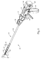
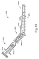
図1は、例示的な外科用ステープル留め及び切断器具(10)を表し、この器具は、ハンドル組立体(20)と、シャフト組立体(30)と、エンドエフェクタ(40)と、を含む。エンドエフェクタ(40)及びシャフト組立体(30)の遠位部分は、外科的処置を行うために、図1に描写されるような非関節動作状態で、トロカールカニューレを通って患者内の手術部位まで挿入するように寸法決めされている。単なる例示として、患者の腹部内に、患者の2本の肋骨の間に、又はその他の部位に、かかるトロカールを挿入してもよい。一部の状況では、器具(10)は、トロカールなしで使用される。例えば、エンドエフェクタ(40)及びシャフト組立体の遠位部分(30)を、開胸術又は他の種類の切開によって直接挿入することができる。本明細書では、「近位」及び「遠位」といった用語は、器具(10)のハンドル組立体(20)を握っている臨床医を基準として使用されていることを理解されたい。したがって、エンドエフェクタ(40)は、より近位にあるハンドル組立体(20)に対して遠位にある。便宜上、また説明を明確にするため、本明細書では「垂直」及び「水平」といった空間的な用語が、図面に対して使用されている点も更に認識されるであろう。しかしながら、外科器具は、多くの配向及び位置で使用されるものであり、これらの用語は、限定的かつ絶対的なものであることを意図するものではない。
I. An exemplary surgical stapler FIG. 1 represents an exemplary surgical stapler and cutting instrument (10), which includes a handle assembly (20), a shaft assembly (30), and an end effector (40). ) And, including. The distal portion of the end effector (40) and shaft assembly (30) passes through the trocar cannula to the surgical site within the patient in a non-joint motion state as depicted in FIG. 1 for surgical procedures. It is sized to be inserted up to. As a mere illustration, such a trocar may be inserted within the patient's abdomen, between the patient's two ribs, or elsewhere. In some situations, instrument (10) is used without a trocar. For example, the end effector (40) and the distal portion (30) of the shaft assembly can be inserted directly by thoracotomy or other type of incision. It should be understood that the terms "proximal" and "distal" are used herein with reference to the clinician holding the handle assembly (20) of the instrument (10). Therefore, the end effector (40) is distal to the more proximal handle assembly (20). It will also be further appreciated that spatial terms such as "vertical" and "horizontal" are used in the drawings for convenience and for clarity. However, surgical instruments are used in many orientations and positions, and these terms are not intended to be limited and absolute.
A.例示的なハンドル組立体及びシャフト組立体
図1〜2に示すように、本例のハンドル組立体(20)は、ピストルグリップ(22)、閉鎖トリガー(24)、及び発射トリガー(26)を含む。各トリガー(24、26)は、以下により詳細に記載されるように、ピストル把持部(22)に向かって、かつそれから離れるように選択的に枢動可能である。ハンドル組立体(20)は、アンビル解放ボタン(25)と、発射ビーム反転スイッチ(27)と、取り外し可能な電池パック(28)と、を更に備える。これらの構成要素についても、以下でより詳細に説明する。勿論、ハンドル組立体(20)は、上記したもののいずれかに加えて又はその代わりに様々な他の構成要素、特徴、及び動作性を有することができる。ハンドル組立体(20)の他の好適な構成は、本明細書の教示を考慮することで当業者には明らかであろう。
A. Illustrative Handle Assembly and Shaft Assembly As shown in FIGS. 1-2, the handle assembly (20) of this example includes a pistol grip (22), a closure trigger (24), and a firing trigger (26). .. Each trigger (24, 26) is selectively pivotable towards and away from the pistol grip (22), as described in more detail below. The handle assembly (20) further comprises an anvil release button (25), a firing beam reversal switch (27), and a removable battery pack (28). These components will also be described in more detail below. Of course, the handle assembly (20) can have various other components, features, and operability in addition to or in place of any of the above. Other suitable configurations of the handle assembly (20) will be apparent to those skilled in the art by considering the teachings herein.
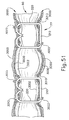
図1〜図3に示すように、本例のシャフト組立体(30)は、外側閉鎖管(32)、関節運動部(34)、及び閉鎖用リング(36)を備え、それは、更にエンドエフェクタ(40)に連結する。閉鎖チューブ(32)はシャフト組立体(30)の長さに沿って延在する。閉鎖リング(36)は、関節運動部(34)の遠位に位置付けられている。閉鎖管(32)及び閉鎖用リング(36)は、ハンドル組立体(20)に対して長手方向に並進するように構成されている。閉鎖チューブ(32)の長手方向並進運動は、関節運動部(34)を介して閉鎖リング(36)に伝達される。閉鎖管(32)及び閉鎖用リング(36)を長手方向に並進するのに使用できる例示の機構は、以下により詳細に記載される。 As shown in FIGS. 1-3, the shaft assembly (30) of this example comprises an outer closure tube (32), a joint motion section (34), and a closure ring (36), which further comprises an end effector. Connect to (40). The closing tube (32) extends along the length of the shaft assembly (30). The closure ring (36) is located distal to the articular movement (34). The closing tube (32) and closing ring (36) are configured to translate longitudinally with respect to the handle assembly (20). The longitudinal translational motion of the closure tube (32) is transmitted to the closure ring (36) via the articulation section (34). Illustrative mechanisms that can be used to translate the closure tube (32) and closure ring (36) longitudinally are described in more detail below.
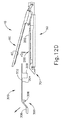
関節運動部(34)は、シャフト組立体(30)の長手方向軸(LA)から所望の角度(α)で横方向へ離れるように、閉鎖リング(36)とエンドエフェクタ(40)を横方向に偏向させるよう動作可能である。エンドエフェクタ(40)は、そのようにして、所望の角度から又は他の理由のために、臓器の背後に到達するか又は組織に近付くことができる。一部の形態においては、関節運動部(34)は、単一の平面に沿ってエンドエフェクタ(40)を偏向させることができる。その他の一部の形態では、関節運動部(34)により、2つ以上の平面に沿ってエンドエフェクタを撓ませることができる。本例では、関節運動は、シャフト組立体(30)の近位端に位置する関節運動制御ノブ(35)によって制御される。ノブ(35)は、シャフト組立体(30)の長手方向軸(LA)に対して垂直な軸を中心として回転可能である。閉鎖用リング(36)及びエンドエフェクタ(40)は、ノブ(35)の回転に反応してシャフト組立体(30)の長手方向軸(LA)に垂直な軸の周りを枢動する。ほんの一例として、ノブ(35)が時計回りに回転すると、関節運動部(34)において閉鎖用リング(36)及びエンドエフェクタ(40)が対応して時計回りに枢動する。関節運動部(34)は、関節運動部(34)が真っ直ぐな構成であるか、又は関節運動構成であるかにかかわらず、閉鎖管(32)が閉鎖用リング(36)まで長手方向に並進するのを伝達するように構成されている。 The articulating portion (34) laterally displaces the closure ring (36) and end effector (40) so that it laterally separates from the longitudinal axis (LA) of the shaft assembly (30) at a desired angle (α). It can be operated to deflect to. The end effector (40) can thus reach behind the organ or approach the tissue from the desired angle or for other reasons. In some forms, the articular movement part (34) can deflect the end effector (40) along a single plane. In some other forms, the articulating section (34) allows the end effector to flex along two or more planes. In this example, the joint movement is controlled by a joint movement control knob (35) located at the proximal end of the shaft assembly (30). The knob (35) is rotatable about an axis perpendicular to the longitudinal axis (LA) of the shaft assembly (30). The closing ring (36) and end effector (40) pivot around an axis perpendicular to the longitudinal axis (LA) of the shaft assembly (30) in response to rotation of the knob (35). As just one example, when the knob (35) rotates clockwise, the closing ring (36) and end effector (40) correspondingly pivot clockwise at the articulating part (34). In the joint movement part (34), the closing tube (32) translates longitudinally to the closing ring (36) regardless of whether the joint movement part (34) has a straight structure or a joint movement structure. It is configured to convey what you do.
一部の形態では、関節運動部(34)及び/又は関節運動制御ノブ(35)は、2014年8月28日に公開された「Surgical Instrument End Effector Articulation Drive with Pinion and Opposing Racks」と題する米国特許出願公開第2014/0243801号(この開示は、参照により本明細書に組み込まれる)の少なくとも一部の教示に従って、構成され操作できる。関節運動部(34)は、また、2014年6月25日に出願された「Articulation Drive Features for Surgical Stapler」と題する米国特許出願第14/314,125号(この開示は、参照により本明細書に組み込まれる)の少なくとも一部の教示に従って、及び/又は、以下の様々な教示に従って、構成され操作できる。関節運動部(34)及び関節動作ノブ(35)が取り得る他の好適な形態は、本明細書の教示を鑑みれば当業者には明らかになるであろう。 In some forms, the joint motion unit (34) and / or the joint motion control knob (35) is the United States entitled "Surgical Instrument End Effect Artist Artification Drive with Pinion and Opposing Racks" published on August 28, 2014. It can be constructed and manipulated in accordance with at least some of the teachings of Patent Application Publication No. 2014/0243801, which disclosure is incorporated herein by reference. The Joint Movement Department (34) also referred to US Patent Application No. 14 / 314,125 entitled "Artification Drive Features for Surgical Stapler" filed June 25, 2014 (this disclosure is herein by reference). Can be configured and operated according to at least some of the teachings (incorporated in) and / or according to various teachings below. Other suitable forms that the joint motion part (34) and the joint motion knob (35) can take will be apparent to those skilled in the art in light of the teachings herein.
図1〜2に示すように、本例のシャフト組立体(30)は更に、回転ノブ(31)を含む。回転ノブ(31)は、シャフト組立体(30)の長手方向軸(LA)の周りを、ハンドル組立体(20)に対して、全シャフト組立体(30)及びエンドエフェクタ(40)を回転するように動作可能である。一部の形態では、回転ノブ(31)は、シャフト組立体(30)の長手方向軸(LA)の周りを、ハンドル組立体(20)に対して、シャフト組立体(30)及びエンドエフェクタ(40)の角度位置を選択的に係止するように動作可能である。例えば、回転ノブ(31)は、シャフト組立体(30)及びエンドエフェクタ(40)がシャフト組立体(30)の長手方向軸(LA)の周りをハンドル組立体(20)に対して回転可能である第1の長手方向位置と、シャフト組立体(30)及びエンドエフェクタ(40)がシャフト組立体(30)の長手方向軸線(LA)の周りを、ハンドル組立体(20)に対して回転できない第2の長手方向位置との間で並進可能である。当然のことながら、シャフト組立体(30)は、上記したもののいずれかに加えて又はその代わりに様々な他の構成要素、特徴、及び動作性を有することができる。あくまで一例として、シャフト組立体(30)の少なくとも一部は、2014年8月28日公開の「Surgical Instrument with Multi−Diameter Shaft」と題する米国特許出願公開第2014/0239038号の教示のうちの少なくともいくつかに従って構成されてもよい。シャフト組立体(30)の他の好適な構成は、本明細書の教示を鑑みれば当業者には明らかになるであろう。 As shown in FIGS. 1 and 2, the shaft assembly (30) of this example further includes a rotary knob (31). The rotary knob (31) rotates the entire shaft assembly (30) and end effector (40) with respect to the handle assembly (20) around the longitudinal axis (LA) of the shaft assembly (30). It is possible to operate like this. In some embodiments, the rotary knob (31) is around the longitudinal axis (LA) of the shaft assembly (30), relative to the handle assembly (20), the shaft assembly (30) and the end effector (30). It is possible to operate so as to selectively lock the angular position of 40). For example, the rotary knob (31) allows the shaft assembly (30) and the end effector (40) to rotate about the longitudinal axis (LA) of the shaft assembly (30) with respect to the handle assembly (20). A first longitudinal position and the shaft assembly (30) and end effector (40) cannot rotate around the longitudinal axis (LA) of the shaft assembly (30) with respect to the handle assembly (20). It can be translated to and from the second longitudinal position. Of course, the shaft assembly (30) can have various other components, features, and operability in addition to or in place of any of the above. As an example, at least a portion of the shaft assembly (30) is at least part of the teachings of US Patent Application Publication No. 2014/0239038 entitled "Surgical Instrument with Multi-Diameter Shaft" published August 28, 2014. It may be configured according to some. Other suitable configurations of the shaft assembly (30) will be apparent to those skilled in the art in light of the teachings herein.
B.例示的なエンドエフェクタ
図1〜3にも示されているように、本例のエンドエフェクタ(40)は、下側ジョー(50)及び枢動可能なアンビル(60)を含む。アンビル(60)は、下側ジョー(50)の対応する湾曲スロット(54)に配置されている一対の一体的な、外側に延在するピン(66)を含む。ピン(66)及びスロット(54)を図5に示す。アンビル(60)は、開放位置(図2及び4に示す)と閉鎖位置(図1、3、及び7A〜7Bに示す)との間で、下側ジョー(50)に向かって、及びそれから離れるように、枢動可能である。「枢動可能」という用語(及び「枢動」を基体とした類義語)の使用は、必ずしも固定軸を中心とした枢動運動を必要とすると理解されるべきではない。例えば、本例において、アンビル(60)は、ピン(66)により画定される軸を中心に枢動し、このピンは、アンビル(60)が下側ジョー(50)に向かって動くと、下側ジョー(50)の湾曲スロット(54)に沿って摺動する。かかる形態では、枢動軸がスロット(54)によって画定された経路に沿って並進する一方で、アンビル(60)はその軸を中心として同時に枢動する。追加的にあるいは代替的に、まず枢動軸がスロット(54)に沿って摺動し、次いで枢動軸がスロット(54)に沿ってある一定の距離を摺動した後に、アンビル(60)が枢動軸を中心として枢動してもよい。そのような摺動/並進枢動運動は、「枢動」、「枢動する」「枢動の」、「枢動可能な」、「枢動している」などの用語内に包含されることを理解されたい。当然のことながら、一部の形態は、固定されたままである、かつスロット又はチャネルなどの内側を並進しない、軸を中心としたアンビル(60)の枢動運動を提供してもよい。
B. Illustrative End Effector As also shown in FIGS. 1-3, the end effector (40) of this example includes a lower jaw (50) and a pivotable anvil (60). The anvil (60) includes a pair of integral, outwardly extending pins (66) located in the corresponding curved slots (54) of the lower jaw (50). Pins (66) and slots (54) are shown in FIG. The anvil (60) is between the open position (shown in FIGS. 2 and 4) and the closed position (shown in FIGS. 1, 3 and 7A-7B) towards and away from the lower jaw (50). As such, it is pivotal. The use of the term "portable" (and a synonym based on "psycho") should not necessarily be understood to require pivotal movement around a fixed axis. For example, in this example, the anvil (60) is pivoted about an axis defined by a pin (66), which pin is down when the anvil (60) moves towards the lower jaw (50). It slides along the curved slot (54) of the side jaw (50). In such a form, the pivot axis translates along the path defined by the slot (54), while the anvil (60) simultaneously pivots about that axis. Additional or alternative, the pivot axis first slides along the slot (54), then the pivot axis slides a certain distance along the slot (54), and then the anvil (60). May be pivoted around the pivot axis. Such sliding / translational kinematics are included within terms such as "pivot", "pivot", "pivot", "pivotable", "pivot". Please understand that. Of course, some forms may provide axially-centered anvil (60) pivotal movements that remain fixed and do not translate inside such as slots or channels.
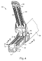
図5に最もわかりやすく示されるように、本例の下側ジョー(50)は、ステープルカートリッジ(70)を受容するように構成されているチャネル(52)を画定する。ステープルカートリッジ(70)はチャネル(52)に挿入することができ、エンドエフェクタ(40)を作動し、その後、ステープルカートリッジ(70)を取り外し、別のステープルカートリッジ(70)と交換することができる。したがって、下側ジョー(50)は、エンドエフェクタ(40)を作動するためのアンビル(60)と位置合わせされてステープルカートリッジ(70)を解放可能に保持する。一部の形態では、下側ジョー(50)は、2014年8月28日に公開された「Installation Features for Surgical Instrument End Effector Cartridge」と題する米国特許出願公開第2014/0239044号(この開示は、参照により本明細書に組み込まれる)の少なくとも一部の教示に従って構成され得る。下側ジョー(50)が取り得る他の好適な形態は、本明細書の教示を鑑みれば当業者には明らかとなるであろう。 As most clearly shown in FIG. 5, the lower jaw (50) of this example defines a channel (52) configured to receive the staple cartridge (70). The staple cartridge (70) can be inserted into the channel (52) to activate the end effector (40), after which the staple cartridge (70) can be removed and replaced with another staple cartridge (70). Therefore, the lower jaw (50) is aligned with the anvil (60) for operating the end effector (40) and holds the staple cartridge (70) releasably. In some forms, Lower Joe (50) published US Patent Application Publication No. 2014/0239044 entitled "Installation Features for Surgical Instrument End Effect Cartridge" published August 28, 2014 (this disclosure is: It may be constructed according to at least some of the teachings (incorporated herein by reference). Other suitable forms that the lower jaw (50) may take will be apparent to those skilled in the art in light of the teachings herein.
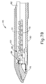
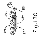
図4〜図6に最もよく示されるように、本例のステープルカートリッジ(70)はカートリッジ本体(71)と、カートリッジ本体(71)の下面に固着されたトレー(76)を備える。カートリッジ本体(71)の上面は、アンビル(60)が閉鎖位置にあるとき、組織を圧縮できるデッキ(73)を提示する。カートリッジ本体(71)は、長手方向に延在するチャネル(72)及び複数のステープルポケット(74)を更に画定する。ステープル(77)は、各ステープルポケット(74)内に位置付けられている。ステープルドライバ(75)はまた、各ステープルポケット(74)内で、対応するステープル(77)の下に、かつトレー(76)の上に位置付けられている。以下でより詳細に説明されるように、ステープルドライバ(75)はステープルポケット(74)内で上向きに並進運動するよう動作可能であり、これによりステープル(77)をステープルポケット(74)を通って上向きに駆動させ、アンビル(60)と係合させる。ステープルドライバ(75)は、楔形スレッド(78)により上向きに駆動され、この楔形スレッドはカートリッジ本体(71)とトレー(76)との間に捕捉されており、これがカートリッジ本体(71)を通って長手方向に並進運動する。楔形スレッド(78)は、一対の傾斜した角度のカム表面(79)を含み、それらは、ステープルドライバ(75)と係合し、それによって、楔形スレッド(78)がカートリッジ(70)を通って長手方向に並進するにつれてステープルドライバ(75)を上方に駆動するように構成されている。例えば、楔形スレッド(78)が図7Aに示すように近位位置にあるとき、ステープルドライバ(75)は下方位置にあり、ステープル(77)はステープルポケット(74)内に位置する。図7Bに示されるように、ナイフ部材(80)の並進運動によって楔型スレッド(78)が遠位位置に駆動されると、楔形スレッド(78)がステープルドライバ(75)を上向きに駆動し、これによりステープルを(77)ステープルポケット(74)から排出させ、アンビル(60)の下面(65)に形成されたステープル成形ポケット(64)内へと駆動する。よって、楔形スレッド(78)が水平寸法に沿って並進すると、ステープルドライバ(75)は垂直寸法に沿って並進する。 As best shown in FIGS. 4-6, the staple cartridge (70) of this example includes a cartridge body (71) and a tray (76) fixed to the underside of the cartridge body (71). The top surface of the cartridge body (71) presents a deck (73) capable of compressing tissue when the anvil (60) is in the closed position. The cartridge body (71) further defines a longitudinally extending channel (72) and a plurality of staple pockets (74). The staples (77) are located within each staple pocket (74). The staple driver (75) is also located within each staple pocket (74), below the corresponding staple (77) and above the tray (76). As described in more detail below, the staple driver (75) can operate to translate upward within the staple pocket (74), thereby allowing the staple (77) to pass through the staple pocket (74). Drive upward to engage the anvil (60). The staple driver (75) is driven upward by a wedge-shaped thread (78), which is trapped between the cartridge body (71) and the tray (76), which passes through the cartridge body (71). Translates in the longitudinal direction. The wedge threads (78) include a pair of tilted angle cam surfaces (79) that engage the staple driver (75), thereby allowing the wedge threads (78) to pass through the cartridge (70). It is configured to drive the staple driver (75) upward as it translates in the longitudinal direction. For example, when the wedge thread (78) is in the proximal position as shown in FIG. 7A, the staple driver (75) is in the lower position and the staple (77) is in the staple pocket (74). As shown in FIG. 7B, when the wedge-shaped thread (78) is driven to the distal position by the translational motion of the knife member (80), the wedge-shaped thread (78) drives the staple driver (75) upward. As a result, the staples are discharged from the (77) staple pockets (74) and driven into the staple molding pockets (64) formed on the lower surface (65) of the anvil (60). Thus, when the wedge thread (78) translates along the horizontal dimension, the staple driver (75) translates along the vertical dimension.
ステープルカートリッジ(70)を多様な方法で変更できることを理解されたい。例えば、本例のステープルカートリッジ(70)は、チャネル(72)の一方の側に、長手方向に延在する2列のステープルポケット(74)を含み、チャネル(72)の他方の側に別の組の長手方向に延在する2列のステープルポケット(74)を含む。しかし、他の一部の形態では、ステープルカートリッジ(70)は、チャネル(72)の両側において3つ、1つ、又は他の数のステープルポケット(74)を含む。一部の変形例では、ステープルカートリッジ(70)は、その開示が参照により本明細書に組み込まれている2013年2月28日に出願の「Integrated Tissue Positioning and Jaw Alignment Features for Surgical Stapler」と題される米国特許出願第13/780,106号の教示の少なくとも一部に従って構成され、動作可能である。追加的にあるいは代替的に、ステープルカートリッジ(70)は、2014年8月28日に公開された「Installation Features for Surgical Instrument End Effector Cartridge」と題する米国特許出願公開第2014/0239044号(この開示は、参照により本明細書に組み込まれる)の少なくとも一部の教示に従って、構成され操作できる。ステープルカートリッジ(70)が取り得る他の好適な形態は、本明細書の教示を鑑みれば当業者には明らかとなるであろう。 It should be understood that the staple cartridge (70) can be modified in a variety of ways. For example, the staple cartridge (70) of this example includes two rows of staple pockets (74) extending longitudinally on one side of the channel (72) and another on the other side of the channel (72). Includes two rows of staple pockets (74) extending longitudinally in the set. However, in some other forms, the staple cartridge (70) includes three, one, or other number of staple pockets (74) on either side of the channel (72). In some variations, the staple cartridge (70) is entitled "Integrated Tissue Positioning and Jaw Alignment Feathers for Surgical Stapler" filed February 28, 2013, the disclosure of which is incorporated herein by reference. It is constructed and operational in accordance with at least some of the teachings of US Patent Application No. 13 / 780,106. Additional or alternative, the staple cartridge (70) is published in US Patent Application Publication No. 2014/0239044 entitled "Installation Features for Surgical Instrument End Effect Cartridge" published on August 28, 2014 (this disclosure is: , Incorporated herein by reference), can be constructed and manipulated according to at least some teachings. Other suitable forms that the staple cartridge (70) can take will be apparent to those skilled in the art in light of the teachings herein.
図4で最もよくわかるように、本例のアンビル(60)は、長手方向に延在するチャネル(62)と、複数のステープル成形ポケット(64)とを備える。チャネル(62)は、アンビル(60)が閉鎖位置にあるとき、ステープルカートリッジ(70)のチャネル(72)と整列するように構成されている。ステープル成形ポケット(64)はそれぞれ、アンビル(60)が閉鎖位置にあるとき、ステープルカートリッジ(70)の対応するステープルポケット(74)の上に置かれるように位置付けられている。ステープル成形ポケット(64)は、ステープル(77)が組織を通してアンビル(60)の中に駆動されるとき、ステープル(77)の脚部を変形させるように構成されている。特に、ステープル成形ポケット(64)は、成形されたステープル(77)を組織内で固定するためにステープル(77)の脚部を曲げるように構成されている。アンビル(60)は、2014年8月28日に公開された「Integrated Tissue Positioning and Jaw Alignment Features for Surgical Stapler」と題する米国特許出願公開第2014/0239042号の教示のうち少なくとも一部、2014年8月28日に公開された「Jaw Closure Feature for End Effector of Surgical Instrument」と題する米国特許出願公開第2014/0239036号の教示のうち少なくとも一部、及び/又は、2014年8月28日に公開された「Staple Forming Features for Surgical Stapling Instrument」と題する米国特許出願公開第2014/0239037号の教示のうち少なくとも一部(これらの開示は、参照により本明細書に組み込まれる)に従って構築されてよい。アンビル(60)が取り得る他の好適な形態は、本明細書の教示を鑑みれば当業者には明らかとなるであろう。 As best seen in FIG. 4, the anvil (60) of this example includes a longitudinally extending channel (62) and a plurality of stapled pockets (64). The channel (62) is configured to align with the channel (72) of the staple cartridge (70) when the anvil (60) is in the closed position. Each staple molded pocket (64) is positioned so that it rests on the corresponding staple pocket (74) of the staple cartridge (70) when the anvil (60) is in the closed position. The staple molding pocket (64) is configured to deform the legs of the staple (77) as the staple (77) is driven into the anvil (60) through the tissue. In particular, the staple molding pocket (64) is configured to bend the legs of the staples (77) to secure the staples (77) in the tissue. Anvil (60) is at least part of the teachings of US Patent Application Publication No. 2014/0239042, entitled "Integrated Tissue Positioning and Jaw Alginment Features for Surgical Stapler," published August 28, 2014, 2014. At least a portion of the teachings of US Patent Application Publication No. 2014/0239036 entitled "Jaw Closure Feature for End Effect Structural Instrument" published on 28th March, and / or published on 28th August 2014. It may be constructed in accordance with at least a portion of the teachings of US Patent Application Publication No. 2014/0239037 entitled "Standard Forming Features for Surgical Stapleing Instrument" (these disclosures are incorporated herein by reference). Other suitable forms that the anvil (60) can take will be apparent to those skilled in the art in light of the teachings herein.
本例では、ナイフ部材(80)は、エンドエフェクタ(40)を通って並進するように構成されている。図5及び7A〜7Bで最もよくわかるように、ナイフ部材(80)は発射ビーム(82)の遠位端に固定されており、この発射ビームは、シャフト組立体(30)の一部を通って延在する。図4及び図6で最もよくわかるように、ナイフ部材(80)は、アンビル(60)及びステープルカートリッジ(70)のチャネル(62、72)内に位置付けられている。ナイフ部材(80)は、ナイフ部材(80)がエンドエフェクタ(40)を通して遠位方向に並進するにつれて、アンビル(60)とステープルカートリッジ(70)のデッキ(73)との間で圧縮されている組織を切断するように構成されている、遠位側に示された切断縁部(84)を含む。上記し、かつ図7A〜図7Bに示すように、ナイフ部材(80)はまた、ナイフ部材(80)がエンドエフェクタ(40)を通して遠位に並進するにつれて楔形スレッド(78)を遠位に駆動し、それによってステープル(74)が組織を通してアンビル(60)に対して打ち込まれ、形成される。ナイフ部材(80)をエンドエフェクタ(40)を通して遠位に駆動するのに使用できる様々な機構については、以下に詳細に記載する。 In this example, the knife member (80) is configured to translate through the end effector (40). As best seen in FIGS. 5 and 7A-7B, the knife member (80) is fixed to the distal end of the firing beam (82), which passes through a portion of the shaft assembly (30). Is extended. As best seen in FIGS. 4 and 6, the knife member (80) is located within the channels (62, 72) of the anvil (60) and staple cartridge (70). The knife member (80) is compressed between the anvil (60) and the deck (73) of the staple cartridge (70) as the knife member (80) translates distally through the end effector (40). Includes a distally shown staple (84) that is configured to cut the tissue. As described above and shown in FIGS. 7A-7B, the knife member (80) also drives the wedge thread (78) distally as the knife member (80) translates distally through the end effector (40). And thereby the staples (74) are driven and formed against the anvil (60) through the tissue. The various mechanisms that can be used to drive the knife member (80) distally through the end effector (40) are described in detail below.
一部の形態では、エンドエフェクタ(40)は、ステープルカートリッジ(70)が下側ジョー(50)に挿入されていないとき、ナイフ部材(80)がエンドエフェクタ(40)を通して遠位側に前進するのを防止するように構成されているロックアウト機構を含む。追加的にあるいは代替的に、エンドエフェクタ(40)は、1回作動された後のステープルカートリッジ(70)(例えば、全てのステープル(77)がそこから配備された)が下側ジョー(50)に挿入されているとき、ナイフ部材(80)がエンドエフェクタ(40)を通して遠位側に前進するのを防止するように構成されているロックアウト機構を含む。あくまで一例として、かかるロックアウト機構は、2014年8月28日に公開された「Lockout Feature for Movable Cutting Member of Surgical Instrument」と題する米国特許出願公開第2014/0239041号(この開示は、参照により本明細書に組み込まれる)の教示のうち少なくとも一部、及び/又は2014年6月25日に出願された「Method of Using Lockout Features for Surgical Stapler Cartridge」と題する米国特許出願第14/314,108号(この開示は、参照により本明細書に組み込まれる)の教示のうち少なくとも一部に従って構築されてよい。ロックアウト機構が取り得る他の好適な形態は、本明細書の教示を鑑みれば当業者には明らかとなるであろう。あるいは、エンドエフェクタ(40)は単に、そのようなロックアウト機構を省略してもよい。 In some embodiments, the end effector (40) advances the knife member (80) distally through the end effector (40) when the staple cartridge (70) is not inserted into the lower jaw (50). Includes a lockout mechanism that is configured to prevent. Additional or alternative, the end effector (40) has a staple cartridge (70) (eg, all staples (77) deployed from it) after it has been activated once to the lower jaw (50). Includes a lockout mechanism configured to prevent the knife member (80) from advancing distally through the end effector (40) when inserted into. As an example only, such a lockout mechanism is published in US Patent Application Publication No. 2014/0239041 entitled "Lockout Feature for Mobile Cutting Member of Surgical Instrument" published on August 28, 2014 (this disclosure is referred to in this reference. At least a portion of the teachings (incorporated in the specification) and / or U.S. Patent Application No. 14 / 314,108 entitled "Method of Using Lockout Features for Surgical Stapler Cartridge" filed June 25, 2014. This disclosure may be constructed in accordance with at least some of the teachings (incorporated herein by reference). Other suitable embodiments of the lockout mechanism will be apparent to those skilled in the art in light of the teachings herein. Alternatively, the end effector (40) may simply omit such a lockout mechanism.
C.例示的なアンビル作動
本例において、アンビル(60)は、閉鎖用リング(36)をエンドエフェクタ(40)に対して遠位側に前進させることによって、下側ジョー(50)に向かって駆動される。閉鎖用リング(36)は、カム作用を介してアンビル(60)と協働し、エンドエフェクタ(40)に対する閉鎖用リング(36)の遠位への並進に反応してアンビル(60)を下側ジョー(50)に向かって駆動する。同様に、閉鎖用リング(36)は、アンビル(60)と協働し、エンドエフェクタ(40)に対する閉鎖用リング(36)の近位側への並進に反応してアンビル(60)を下側ジョー(50)から離れて開放することができる。あくまで一例として、閉鎖用リング(36)及びアンビル(60)は、2014年8月28日に公開された「Jaw Closure Feature for End Effector of Surgical Instrument」と題する米国特許出願公開第2014/0239036号(この開示は、参照により本明細書に組み込まれる)の教示のうち少なくとも一部に従って、及び/又は、2014年6月25日に出願された「Jaw Opening Feature for Surgical Stapler」と題する米国特許出願第14/314,108号(この開示は、参照により本明細書に組み込まれる)の教示のうち少なくとも一部に従って相互作用できる。エンドエフェクタ(40)に対して閉鎖用リング(36)を長手方向に並進するのに使用できる例示の機構は、以下により詳細に記載される。
C. Illustrative Anvil Actuation In this example, the anvil (60) is driven towards the lower jaw (50) by advancing the closing ring (36) distal to the end effector (40). To. The closing ring (36) works with the anvil (60) via a cam action to move down the anvil (60) in response to the distal translation of the closing ring (36) with respect to the end effector (40). Drive toward the side jaw (50). Similarly, the closing ring (36) works with the anvil (60) to lower the anvil (60) in response to the proximal translation of the closing ring (36) to the end effector (40). It can be released away from Joe (50). As an example, the Closing Ring (36) and Anvil (60) are published in US Patent Application Publication No. 2014/0239036 entitled "Jaw Color Feature for End Effector of Surgical Instrument" published on August 28, 2014. This disclosure follows at least part of the teachings (incorporated herein by reference) and / or US Patent Application No. 1 entitled "Jaw Opening Feature for Surgical Stapler" filed June 25, 2014. You can interact according to at least some of the teachings of 14 / 314, 108 (this disclosure is incorporated herein by reference). An exemplary mechanism that can be used to translate the closing ring (36) longitudinally relative to the end effector (40) is described in more detail below.
上記したように、ハンドル組立体(20)は、ピストル把持部(22)と、閉鎖トリガー(22)とを含む。また、上記したように、アンビル(60)は、閉鎖用リング(36)の遠位前進に反応して下側ジョー(50)に向かって閉鎖される。本例において、閉鎖トリガー(24)は、閉鎖管(32)及び閉鎖用リング(36)を遠位側に駆動させるように、ピストル把持部(22)に向かって枢動可能である。本明細書の教示を考慮することで、ピストル把持部(22)に向かう閉鎖トリガー(24)の枢軸運動を、ハンドル組立体(20)に対する閉鎖管(32)及び閉鎖用リング(36)の遠位への並進に変換するのに使用され得る様々な好適な構成要素が、当業者には明らかであろう。閉鎖トリガー(24)は、アンビル(60)が、下側ジョー(50)に対して完全な閉鎖位置になるような完全な枢動状態に達するとき、ハンドル組立体(20)のロック機構は、トリガー(24)及び閉鎖管(32)の位置を係止し、それによってアンビル(60)を下側ジョー(50)に対して完全な閉鎖位置に係止する。これらの係止機構は、アンビル解放ボタン(25)の作動によって解放される。アンビル解放ボタン(25)は、ピストル把持部(22)をつかむ操作者の手の親指で作動されるように構成され、位置付けられている。言い換えると、操作者は、ピストル把持部(22)を片手でつかみ、閉鎖トリガー(24)を同じ手の1本又は2本以上の指で作動し、その後、同じ手によるピストル把持部(22)のつかみを解放する必要なく、アンビル解放ボタン(25)を同じ手の親指で作動することができる。本明細書の教示を考慮することで、アンビル(60)の作動に使用できる他の好適な機構が当業者に明らかとなるであろう。 As described above, the handle assembly (20) includes a pistol grip (22) and a closing trigger (22). Also, as described above, the anvil (60) is closed towards the lower jaw (50) in response to the distal advance of the closing ring (36). In this example, the closure trigger (24) is pivotable towards the pistol grip (22) to drive the closure tube (32) and closure ring (36) distally. Taking into account the teachings herein, the pivotal movement of the closure trigger (24) towards the pistol grip (22) is distant from the closure tube (32) and closure ring (36) relative to the handle assembly (20). Various suitable components that can be used to translate into a place will be apparent to those skilled in the art. When the closing trigger (24) reaches a fully pivoted state such that the anvil (60) is in a fully closed position with respect to the lower jaw (50), the locking mechanism of the handle assembly (20) is It locks the positions of the trigger (24) and the closing tube (32), thereby locking the anvil (60) in a completely closed position with respect to the lower jaw (50). These locking mechanisms are released by the operation of the anvil release button (25). The anvil release button (25) is configured and positioned to be actuated by the thumb of the operator's hand gripping the pistol grip (22). In other words, the operator grabs the pistol grip (22) with one hand, activates the closure trigger (24) with one or more fingers of the same hand, and then operates the pistol grip (22) with the same hand. The anvil release button (25) can be operated with the thumb of the same hand without the need to release the grip. By considering the teachings herein, other suitable mechanisms that can be used to operate the anvil (60) will become apparent to those of skill in the art.
D.発射ビームの例示的作動
本発明の例では、器具(10)は、発射ビーム(82)の電動制御を提供する。特に、器具(10)は、発射トリガー(26)のピストル把持部(22)に向かう枢動に応答して発射ビーム(82)を遠位に駆動するように構成された、電動構成要素を備える。一部の形態では、モーター(図示せず)がピストル把持部(22)内に含まれ、電池パック(28)から電力を受信する。このモーターは、モーターの駆動シャフトの回転運動を、発射ビーム(82)の線形移動に変換する伝送組立体(図示せず)に連結される。一部のこのような形態では、アンビル(60)が下側ジョー(50)に対して完全閉鎖位置にあるとき、発射ビーム(82)は遠位に前進しかできない。図7A〜7Bを参照して上述されるように、発射ビーム(82)が遠位に前進して組織を切断し、ステープル(77)を駆動した後、発射ビーム(82)用の駆動組立体は、自動的に反転し、発射ビーム(82)を近位に後退位置に戻すように駆動できる(例えば、図7Bに示される位置から図7Aに示される位置まで戻す)。あるいは、操作者は、発射ビーム(82)用の駆動組立体を反転して発射ビーム(82)を近位位置に後退できる、発射ビーム反転スイッチ(27)を作動してよい。本例のハンドル組立体(20)は、機械的脱出をもたらすように操作可能であり、操作者が手動で発射ビーム(82)を近位に後退させることを可能にする(例えば、発射ビーム(82)が遠位位置にある間に電力損失した場合など)、脱出機構(21)を更に備える。
D. Illustrative Actuation of Launch Beam In the example of the present invention, the instrument (10) provides electric control of the launch beam (82). In particular, the instrument (10) comprises an electric component configured to drive the firing beam (82) distally in response to a pivot of the firing trigger (26) towards the pistol grip (22). .. In some embodiments, a motor (not shown) is included within the pistol grip (22) to receive power from the battery pack (28). The motor is coupled to a transmission assembly (not shown) that transforms the rotational motion of the motor's drive shaft into a linear movement of the firing beam (82). In some such forms, the firing beam (82) can only advance distally when the anvil (60) is in a completely closed position with respect to the lower jaw (50). As described above with reference to FIGS. 7A-7B, the launch beam (82) advances distally to cut tissue, drive the staples (77), and then drive assembly for the launch beam (82). Can be automatically inverted and driven to return the firing beam (82) to the proximally retracted position (eg, from the position shown in FIG. 7B to the position shown in FIG. 7A). Alternatively, the operator may activate a launch beam reversal switch (27) that can flip the drive assembly for the launch beam (82) to retract the launch beam (82) to a proximal position. The handle assembly (20) of this example can be manipulated to result in mechanical escape, allowing the operator to manually retract the firing beam (82) proximally (eg, firing beam (eg, firing beam). If power is lost while the 82) is in the distal position), an escape mechanism (21) is further provided.
あくまで一例として、発射ビーム(82)の電動化作動をもたらすように操作可能な機構は、2012年7月3日に発行された「Motor−Driven Surgical Instrument」と題する米国特許第8,210,411号(この開示は、参照により本明細書に組み込まれる)の教示のうち少なくとも一部に従って、構成され、操作することができる。別の単なる例示例として、発射ビーム(82)の電動化作動をもたらすように操作可能な機構は、2013年6月4日に発行された「Motor−Driven Surgical Cutting Instrument with Electric Actuator Directional Control Assembly」と題する米国特許第8,453,914号(この開示は、参照により本明細書に組み込まれる)の教示のうち少なくとも一部に従って、構成され、操作することができる。更に別の単なる例示例として、発射ビーム(82)の電動化作動をもたらすように操作可能な機構は、2014年3月26日に出願された「Surgical Instrument Comprising a Sensor System」と題する米国特許出願第14/226,142号(この開示は、参照により本明細書に組み込まれる)の教示のうち少なくとも一部に従って、構成され、操作することができる。 As an example, the mechanism that can be operated to bring about the electrification of the firing beam (82) is US Pat. No. 8,210,411, entitled "Motor-Driven Surgical Instrument," issued July 3, 2012. It can be constructed and operated in accordance with at least some of the teachings of issue (this disclosure is incorporated herein by reference). As another mere example, a mechanism that can be operated to bring about the electrification of the firing beam (82) is the "Motor-Driven Surgical Cutting Instrument with Electrical Actuator Digital Control" published on June 4, 2013. It can be constructed and manipulated in accordance with at least some of the teachings of US Pat. No. 8,453,914, entitled (this disclosure is incorporated herein by reference). Yet another mere example, a mechanism that can be manipulated to provide electrification of the firing beam (82) is a US patent application entitled "Surgical Instrument Comprising a Sensor System" filed on March 26, 2014. It can be constructed and manipulated in accordance with at least some of the teachings of No. 14 / 226,142 (this disclosure is incorporated herein by reference).
発射ビーム(82)の電動化をもたらすために使用できるその他好適な構成要素、特徴部、及び構成は、本明細書の教示を鑑みれば当業者には明らかになるであろう。また、他の形態において、発射ビーム(82)のマニュアル駆動が提供され、モーターが省かれてもよいことも理解されたい。あくまで一例として、発射ビーム(82)は、本明細書で引用されるその他の参照文献の教示のうち少なくとも一部に従って手動で作動することができる。 Other suitable components, features, and configurations that can be used to result in electrification of the firing beam (82) will be apparent to those skilled in the art in light of the teachings herein. It should also be appreciated that in other embodiments, manual drive of the firing beam (82) is provided and the motor may be omitted. As an example only, the firing beam (82) can be manually actuated according to at least some of the teachings of other references cited herein.
図8は、組織(90)を通じた1回のストロークを通して作動されたエンドエフェクタ(40)を示している。示されるように、切断縁部(84)(図8では不明瞭)は、組織(90)を切断したが、ステープルドライバ(75)は、切断縁部(84)が作り出した切断線の各側で、組織(90)を通してステープル(77)の2本の交互の列を駆動した。この例では、全てのステープル(77)が切断線とほぼ平行に向いているが、ステープル(77)は、任意の好適な向きで位置付けされ得る点を理解されたい。本例では、第1のストロークが完了した後にエンドエフェクタ(40)をトロカールから引き抜き、使用済みのステープルカートリッジ(70)を新しいステープルカートリッジ(70)と交換し、その後、エンドエフェクタ(40)を再びトロカールを通じて挿入して、ステープル留めする部位に到達させて更なる切断及びステープル留めを行う。所望の量の切断及びステープル(77)が与えられるまで、このプロセスを繰り返すことができる。トロカールを通じた挿入及び抜脱を助けるためにはアンビル(60)を閉鎖する必要があり、ステープルカートリッジ(70)の交換を助けるためにはアンビル(60)を開放する必要がある。 FIG. 8 shows an end effector (40) actuated through a single stroke through tissue (90). As shown, the cutting edge (84) (obscured in FIG. 8) cut the tissue (90), while the staple driver (75) cut each side of the cutting line created by the cutting edge (84). Driven two alternating rows of staples (77) through tissue (90). It should be understood that in this example, all staples (77) are oriented approximately parallel to the cutting line, but staples (77) can be positioned in any suitable orientation. In this example, the end effector (40) is pulled out of the trocar after the first stroke is complete, the used staple cartridge (70) is replaced with a new staple cartridge (70), and then the end effector (40) is replaced again. Insert through the trocar to reach the stapling site for further cutting and stapling. This process can be repeated until the desired amount of cutting and staples (77) are given. The anvil (60) needs to be closed to help insert and remove through the trocar, and the anvil (60) needs to be opened to help replace the staple cartridge (70).
各作動ストロークの間に、ステープル(77)が組織に貫通して打ち込まれるのとほぼ同時に、切断縁部(84)が組織を切断することができる点を理解されたい。本例において、切断縁部(84)は、ステープル(77)の駆動動作よりもごくわずかに遅れて進むので、ステープル(47)は、切断縁部(84)が組織の同じ領域を通過する直前に組織を通して駆動されるが、この順序を逆にすることができる点、又は、切断縁部(84)が、隣り合うステープルと直接的に一緒に動いてもよい点を理解されたい。図8は、2層(92、94)の組織(90)で作動しているエンドエフェクタ(40)を示しているが、エンドエフェクタ(40)は、1層の組織(90)、又は2層(92、94)を超える組織を通じて作動され得る点を理解されたい。また、切断縁部(84)が形成する切断線に隣接するステープル(77)の成形及び位置決めにより、切断線において組織を実質的にシールすることができ、これにより、切断線での出血及び/又は他の体液の漏出を低減又は防止することができる点も理解されたい。更にまた、図8は、2つの概ね平坦で並置した組織の平面層(92、94)において作動されているエンドエフェクタ(40)を示すが、エンドエフェクタ(40)は、環状構造、例えば血管、消化管のセクションなどにわたって作動され得ることを理解されたい。図8は、したがって、エンドエフェクタ(40)についての意図された使用におけるなんらかの制限を示すものとして見られるべきではない。器具(10)を使用することができる様々な適当な状況及び手術は、本明細書の教示を鑑みれば当業者には明らかとなるであろう。 It should be appreciated that during each working stroke, the cutting edge (84) can cut the tissue at about the same time that the staple (77) is driven through the tissue. In this example, the staple (84) advances just slightly behind the driving action of the staple (77), so that the staple (47) is just before the cut edge (84) passes through the same area of tissue. It should be understood that it is driven through the tissue, but the order can be reversed, or that the cutting edge (84) may move directly with the adjacent staples. FIG. 8 shows an end effector (40) operating in two layers (92, 94) of tissue (90), where the end effector (40) is one layer of tissue (90) or two layers. It should be understood that it can be operated through more than (92, 94) tissues. Also, the molding and positioning of the staples (77) adjacent to the cutting line formed by the cutting edge (84) can substantially seal the tissue at the cutting line, thereby causing bleeding and / or bleeding at the cutting line. Or it should be understood that the leakage of other body fluids can be reduced or prevented. Furthermore, FIG. 8 shows an end effector (40) operating in a planar layer (92, 94) of two generally flat and juxtaposed tissues, where the end effector (40) is an annular structure, eg, a blood vessel. It should be understood that it can be operated over sections of the gastrointestinal tract. FIG. 8 should therefore not be seen as indicating any limitation in the intended use of the end effector (40). Various suitable situations and surgeries in which the instrument (10) can be used will be apparent to those skilled in the art in light of the teachings herein.
器具(10)の任意の他の構成要素又は機構は、本明細書に引用される様々な参照文献のうちいずれかに従って構成され、動作可能であることも理解されたい。器具(10)に行うことができる更なる例示的な改変例について以下により詳細に記載する。以下の教示を器具(10)に組み込むことができる様々な適当な方法が当業者には明らかであろう。同様に、以下の教示を本明細書で引用された参考文献の様々な教示と組み合わせることができる様々な好適な方法が当業者には明らかであろう。したがって、以下の教示が、本明細書に引用される様々な参考文献で教示されている様々な器具に容易に組み入れることができることが理解されよう。また、以下の教示は、本明細書に引用される参考文献に教示される器具(10)又は装置に限定されない点も理解されたい。以下の教示は、外科用ステープラとして分類されない器具を含む他の様々な種類の器具に容易に応用することができる。以下の教示を適用することができる他の様々な適当な装置及び状況は、本明細書の教示を鑑みれば当業者には明らかとなるであろう。 It should also be appreciated that any other component or mechanism of instrument (10) is constructed and operational according to any of the various references cited herein. Further exemplary modifications that can be made to instrument (10) are described in more detail below. Various suitable methods will be apparent to those skilled in the art in which the following teachings can be incorporated into instrument (10). Similarly, various suitable methods will be apparent to those skilled in the art in which the following teachings can be combined with the various teachings of the references cited herein. Therefore, it will be appreciated that the following teachings can be easily incorporated into the various instruments taught in the various references cited herein. It should also be understood that the following teachings are not limited to the instruments (10) or devices taught in the references cited herein. The following teachings can be readily applied to various other types of instruments, including instruments that are not classified as surgical staplers. Various other suitable devices and situations to which the following teachings can be applied will be apparent to those skilled in the art in light of the teachings herein.
II.外科用ステープラ用の例示的な支持具
上記のように、場合によっては、ステープル(77)によってもたらされる組織(90)の機械的締結を補強するため、エンドエフェクタ(40)に支持材料を備えることが望ましい場合がある。かかる支持具は、適用したステープル(77)が組織(90)から引き抜かれるのを防ぐことができ、ステープル(77)の適用部位又はその付近の組織(90)が裂けるリスクを別の方法で低減することができる。ステープル(77)のラインに構造的支持及び一体性もたらすことに加え、又はそれに代わるものとして、支持具は、空隙又は間隙の充填、治療薬の投与などのその他様々な種類の効果、及び/又は別の効果をもたらすことができる。場合によっては、支持具は、ステープルカートリッジ(70)のデッキ(73)上に提供され得る。いくつかの別の場合では、支持具は、ステープルカートリッジ(70)に面するアンビル(60)の表面上に提供され得る。第1支持具がステープルカートリッジ(70)のデッキ(73)上に提供され得る一方で、第2支持具が同じエンドエフェクタ(40)のアンビル(60)上に提供され得ることも理解されよう。支持具が取り得る様々な形態の例を、以下により詳細に記載する。支持具がステープルカートリッジ(70)又はアンビル(60)に固定され得る様々な方法も、以下により詳細に記載される。
II. Exemplary Supports for Surgical Staples As mentioned above, the end effector (40) may be provided with a support material to reinforce the mechanical fastening of the tissue (90) provided by the staples (77). May be desirable. Such a support can prevent the applied staple (77) from being pulled out of the tissue (90) and otherwise reduce the risk of tearing the tissue (90) at or near the application site of the staple (77). can do. In addition to, or in lieu of, providing structural support and integrity to the staple (77) line, the support provides various other types of effects, such as filling voids or gaps, administration of therapeutic agents, and / or. It can have another effect. In some cases, the support may be provided on the deck (73) of the staple cartridge (70). In some other cases, the support may be provided on the surface of the anvil (60) facing the staple cartridge (70). It will also be appreciated that the first support can be provided on the deck (73) of the staple cartridge (70), while the second support can be provided on the anvil (60) of the same end effector (40). Examples of the various forms that the support can take are described in more detail below. Various methods by which the support can be secured to the staple cartridge (70) or anvil (60) are also described in more detail below.
A.外科用ステープラ用の支持具例示的な構成
図9は、基本的構成の例示的な支持具組立体(100)を示す。この例の支持具組立体(100)は、支持具本体(102)と、上側接着層(104)と、下側接着層(106)と、を備える。本例において、支持具本体(102)は、ステープル(77)のラインを構造的に支持するように構成されている、強くはあるが可撓性の材料を含む。追加的にあるいは代替的に、支持具本体(102)は、例えば、血液を凝固させ、かつ組織(90)に沿って切断及び/又はステープル留めされた手術部位における出血を低減させるのを助ける、フィブリンなどの止血薬を含む材料を含んでよい。
A. Illustrative Configuration of Supports for Surgical Staplers FIG. 9 shows an exemplary support assembly (100) with a basic configuration. The support assembly (100) of this example includes a support body (102), an upper adhesive layer (104), and a lower adhesive layer (106). In this example, the support body (102) comprises a strong but flexible material that is configured to structurally support the staple (77) line. Additional or alternative, the support body (102) helps, for example, to coagulate blood and reduce bleeding at the surgical site cut and / or stapled along the tissue (90). Materials containing hemostatic agents such as fibrin may be included.
別の単なる例示例として、支持具本体(102)は、血液を凝固させ、かつ手術部位における出血量を低減させるのを支持具本体(102)が助けることができるように、他の添加剤又はトロンビンなどの止血薬を含んでもよい。かかる添加物の止血能力はまた、接着剤及びシーラントとしてのかかる添加物の使用にも寄与し得る。これらの薬剤は、例えば、かかる血液を取り囲む組織がくっつき合うこと可能にする手術部位での血液を凝固させるのを補助し得、かつステープル留めされた組織部位に沿って漏れることを防止し得る。支持具本体(102)に組み入れることができる他の添加剤又は試薬としては、更に薬液又はマトリックス成分を挙げることができるがこれらに限定されない。あくまで一例として、支持具本体(102)は、天然の又は遺伝子操作されている吸収性ポリマー又は合成吸湿性ポリマー又はそれらの混合物を含むことができる。天然の又は遺伝操作された吸収性ポリマーの単に例示的な例は、蛋白質、多糖及びその組み合わせである。使用することができる蛋白質の単に例示的な例としては、プロトロンビン、トロンビン、フィブリノーゲン、フィブリン、フィブロネクチン、ヘパリナーゼ、第X/Xa因子、第VII/VIIa因子、第IX因子/IXa、第XI/XIa因子、第XII/XIIa因子、組織因子、バトロキソビン、アンクロド、エカリン、フォンビルブラント因子、コラーゲン、エラスチン、アルブミン、ゼラチン、血小板面糖蛋白質、バソプレシン、バソプレシンアナログ、エピネフリン、セレクチン、プロコアギュラントベノム(procoagulant venom)、プラスミノーゲン活性化因子抑制因子、血小板活性化剤、止血活性を有する合成ペプチド及び/又はその組み合わせがある。また多糖には、セルロース、アルキルセルロース、例えば、メチルセルロース、アルキルヒドロキシアルキルセルロース、ヒドロキシアルキルセルロース、セルロース硫酸、カルボキシメチルセルロースの塩、カルボキシメチルセルロース、カルボキシエチルセルロース、キチン、カルボキシメチルキチン、ヒアルロン酸、ヒアルロン酸の塩、アルギネート、アルギン酸、アルギン酸プロピレングリコール、グリコーゲン、デキストラン、デキストラン硫酸、カードラン、ペクチン、プルラン、キサンタン、コンドロイチン、コンドロイチン硫酸類、カルボキシメチルデキストラン、カルボキシメチルキトサン、キトサン、ヘパリン、ヘパリン硫酸、ヘパラン、ヘパラン硫酸、デルマタン硫酸、ケラタン硫酸、カラギーナン類、キトサン、デンプン、アミロース、アミロペクチン、ポリ−N−グルコサミン、ポリマンヌロン酸、ポリグルクロン酸、ポリグルロン酸、及び上記のいずれかの誘導体を挙げることができる。合成吸収性ポリマーの例は、脂肪族ポリエステルポリマー、コポリマー、及び/又はこれらの組み合わせである。脂肪族ポリエステルは、典型的には、乳酸、ラクチド(L−、D−、メソ形、及びD、L混合物を含む)、グリコール酸、グリコリド、ε−カプロラクトン、p−ジオキサノン(1,4−ジオキサン−2−オン)、及びトリメチレンカーボネート(1,3−ジオキサン−2−オン)を含むが、これらに限定されないモノマーの開環重合において合成される。医療用流体又はマトリックスで使用することができる他の好適な化合物、材料、物質などは、本明細書の教示を考えて、当業者には明白であろう。 As another mere example, the support body (102) is provided with other additives or other additives so that the support body (102) can help coagulate blood and reduce bleeding at the surgical site. Hemostatic agents such as thrombin may be included. The hemostatic capacity of such additives can also contribute to the use of such additives as adhesives and sealants. These agents may, for example, help coagulate the blood at the surgical site that allows the tissue surrounding such blood to stick together and prevent leakage along the stapled tissue site. Other additives or reagents that can be incorporated into the support body (102) may include, but are not limited to, chemical solutions or matrix components. As an example, the support body (102) can include a natural or genetically engineered absorbent polymer or synthetic hygroscopic polymer or a mixture thereof. The only exemplary examples of natural or genetically engineered absorbent polymers are proteins, polysaccharides and combinations thereof. Simply exemplary examples of proteins that can be used are prothrombin, thrombin, fibrinogen, fibrin, fibronectin, hemostasis, factor IX / Xa, factor VII / VIIa, factor IX / IXa, factor XI / XIa. , Factor XII / XIIa, Tissue Factor, Thrombin, Anclode, Ecarin, Fonvirbrand Factor, Collagen, Elastin, Albumin, Gelatin, Platelet Surface Glucose Protein, Basopresin, Basopresin Analog, Epinephrine, Selectin, Procoagulant venom ), Plasminogen activator suppressor, platelet activator, synthetic peptide having hemostatic activity and / or a combination thereof. In addition, polysaccharides include cellulose and alkyl cellulose, for example, methyl cellulose, alkyl hydroxyalkyl cellulose, hydroxyalkyl cellulose, cellulose sulfate, carboxymethyl cellulose salt, carboxymethyl cellulose, carboxyethyl cellulose, chitin, carboxymethyl chitin, hyaluronic acid, and hyaluronic acid salt. , Arginate, alginate, propylene glycol alginate, glycogen, dextran, dextran sulfate, curdran, pectin, purulan, xanthane, chondroitin, chondroitin sulfates, carboxymethyl dextran, carboxymethyl chitosan, chitosan, heparin, heparin sulfate, heparan, heparan sulfate. , Dermatin sulfate, keratane sulfate, carrageenans, chitosan, starch, amylose, amylopectin, poly-N-glucosamine, polymannuronic acid, polyglucuronic acid, polyglulonic acid, and any derivative of the above. Examples of synthetically absorbent polymers are aliphatic polyester polymers, copolymers, and / or combinations thereof. Polyesters typically include lactic acid, lactide (including L-, D-, mesoforms, and D, L mixtures), glycolic acid, glycolide, ε-caprolactone, p-dioxanone (1,4-dioxane). -2-one) and trimethylene carbonate (1,3-dioxane-2-one) are synthesized in ring-opening polymerization of monomers including, but not limited to, these. Other suitable compounds, materials, substances, etc. that can be used in medical fluids or matrices will be apparent to those of skill in the art given the teachings herein.
あるいは、支持具本体(102)は、繊維パッド、発泡体、メッシュ、織物、並びに/又は、接着剤及び/若しくは他種の薬液を含むことができる別の構造体を含むことができる。追加的にあるいは代替的に、支持具本体(102)は単純に、メッシュ、織物、及び/又は、組織(90)を通して適用されたステープル(77)のラインに構造的支持又は一体性をもたらすように構築される、いくつかの別の構造体を備えてよい。このような材料及び構造体は比較的薄くてよく、場合によっては、実質的に非圧縮性であってよい。あくまで更なる例として、支持具本体(102)は、2012年9月27日に公開された「Tissue Thickness Compensator Comprising Controlled Release and Expansion」と題する米国特許出願公開第2012/0241493号(この開示は、参照により本明細書に組み込まれる)、2013年3月21日に公開された「Surgical Instrument and Buttress Material」と題する米国特許出願公開第2013/0068816号(この開示は、参照により本明細書に組み込まれる)、2013年3月14日に公開された「Surgical Instrument with Fluid Fillable Buttress」と題する米国特許出願公開第2013/0062391号(この開示は、参照により本明細書に組み込まれる)、2013年3月21日に公開された「Fibrin Pad Matrix with Suspended Heat Activated Beads of Adhesive」と題する米国特許出願公開第2013/0068820号(この開示は、参照により本明細書に組み込まれる)、2013年4月4日に公開された「Attachment of Surgical Staple Buttress to Cartridge」と題する米国特許出願公開第2013/0082086号(この開示は、参照により本明細書に組み込まれる)、2013年2月14日に公開された「Device for Applying Adjunct in Endoscopic Procedure」と題する米国特許出願公開第2013/0037596号(この開示は、参照により本明細書に組み込まれる)、2013年3月14日に公開された「Resistive Heated Surgical Staple Cartridge with Phase Change Sealant」と題する米国特許出願公開第2013/0062393号(この開示は、参照により本明細書に組み込まれる)、2013年3月28日に公開された「Surgical Staple Assembly with Hemostatic Feature」と題する米国特許出願公開第2013/0075446号(この開示は、参照により本明細書に組み込まれる)、2013年3月14日に公開された「Surgical Staple Cartridge with Self−Dispensing Staple Buttress」と題する米国特許出願公開第2013/0062394号(この開示は、参照により本明細書に組み込まれる)、2013年3月28日に公開された「Anvil Cartridge for Surgical Fastening Device」と題する米国特許出願公開第2013/0075445号(この開示は、参照により本明細書に組み込まれる)、2013年3月28日に公開された「Adjunct Therapy for Applying Hemostatic Agent」と題する米国特許出願公開第2013/0075447号(この開示は、参照により本明細書に組み込まれる)、及び/又は、2013年10月3日に公開された「Tissue Thickness Compensator Comprising a Plurality of Medicaments」と題する米国特許出願公開第2013/0256367号(この開示は、参照により本明細書に組み込まれる)の教示のうち少なくとも一部に従って、構築されてよい。 Alternatively, the support body (102) can include a fiber pad, foam, mesh, fabric, and / or another structure that can contain an adhesive and / or other chemicals. Additional or alternative, the support body (102) simply provides structural support or integrity to the staple (77) line applied through the mesh, fabric, and / or tissue (90). It may have several other structures constructed in. Such materials and structures may be relatively thin and, in some cases, substantially incompressible. As a further example, the support body (102) is described in US Patent Application Publication No. 2012/0241493 entitled "Tisue Tickness Compensator Comprising Control and Release and Expansion" published on September 27, 2012 (this disclosure is: US Patent Application Publication No. 2013/0068816, published March 21, 2013, entitled "Surgical Instrument and Buttress Material" (incorporated herein by reference) (this disclosure is incorporated herein by reference). , 2013/0062391 (this disclosure is incorporated herein by reference), entitled "Surgical Instrument with Fluid File Buttress," published March 14, 2013. US Patent Application Publication No. 2013/0068820, entitled "Fibrin Pad Matrix with Suspended Heat Activated Beads of Advanced," published March 21, 2013 (this disclosure is incorporated herein by reference), April 4, 2013. Published on February 14, 2013, US Patent Application Publication No. 2013/0082086, entitled "Attitude of Surgical Standard Buttress to Cartridge", published today (this disclosure is incorporated herein by reference). US Patent Application Publication No. 2013/0037596 (this disclosure is incorporated herein by reference) entitled "Device for Applying Adjunct in Endoscopic Procedure", "Resistive Heated Sur" published on March 14, 2013. US Patent Application Publication No. 2013/0062393 (this disclosure is incorporated herein by reference) entitled "Cartridge with Phase Change Sealant", "Surgical Type Assembly with He" published March 28, 2013. US Patent Application Publication No. 2013/0075446 entitled "Mostatic Featur" (this disclosure is incorporated herein by reference), "Surgical Standard Cartridge with Self-Dispensing Standard Buttre" published March 14, 2013. US Patent Application Publication No. 2013/0062394 (this disclosure is incorporated herein by reference), US Patent Application Publication entitled "Anvil Cartridge for Surgical Fastening Device" published March 28, 2013. 2013/0075445 (this disclosure is incorporated herein by reference), US Patent Application Publication No. 2013/0075447, entitled "Adjunct Therapy for Applying Hemostatic Agent," published March 28, 2013 (this disclosure is incorporated herein by reference). This disclosure is incorporated herein by reference) and / or US Patent Application Publication No. 2013/0256367 (US Patent Application Publication No. 2013/0256367) entitled "Tisue Tickness Compensator Comprising a Plurality of Medicals" published October 3, 2013. This disclosure may be constructed in accordance with at least some of the teachings (incorporated herein by reference).
本例において、支持具本体(102)は、Ethicon US,LLC.のVICRYL(登録商標)(ポリグラクチン910)材料の織メッシュを含む。VICRYL(登録商標)織メッシュは、それぞれグリコール酸及び乳酸由来の合成吸収性コポリマーであるグリコリド及びラクチドから調製される。この緊密に織られたメッシュは、不活性、非抗原性、非発熱性であり、吸収中の組織反応が軽度であるとわかっている、VICRYL(登録商標)合成吸収性縫合糸に使用されている繊維と同一の構成である、コーティングと染色がなされていない繊維から調製される。VICRYL(登録商標)織メッシュは、治癒過程中に一時的な支持をもたらす支持具としての使用を対象としている。あるいは、任意のその他好適な材料又は材料の組み合わせを、VICRYL(登録商標)材料に加えて、又はこれに代わるものとして使用し、支持具本体(102)を形成してよい。 In this example, the support body (102) is the Ethicon US, LLC. Includes a woven mesh of VICRYL® (Polygractin 910) material. The VICRYL® woven mesh is prepared from glycolide and lactide, which are synthetically absorbent copolymers derived from glycolic acid and lactic acid, respectively. This tightly woven mesh is used in VICRYL® synthetic absorbable sutures, which are inactive, non-antigenic, non-pyrogenic and have been found to have mild tissue reactions during absorption. It is prepared from uncoated and undyed fibers that have the same composition as the fibers. The VICRYL® woven mesh is intended for use as a support that provides temporary support during the healing process. Alternatively, any other suitable material or combination of materials may be used in addition to or as an alternative to the VICRYL® material to form the support body (102).
支持具本体(102)がメッシュとして形成される形態では、様々な種類のメッシュ形状を使用できると理解されたい。あくまで一例として、支持具本体(102)は、織メッシュ、編メッシュ、又は縦編メッシュとして形成されてよい。支持具本体(102)がメッシュとして形成されるか否かに関わらず、一部の例では、支持具本体(102)は多孔性である。以下により詳細に説明するように、接着層(104、106)は支持具本体(102)上に提供され、支持具本体(102)をアンビル(60)の下面(65)又はステープルカートリッジ(70)のデッキ(73)に接着できる。支持具本体(102)が多孔性であるいくつかの形態では、接着層(104、106)を形成する材料は、支持具本体(102)を通過し、接着層(104、106)が配置されている表面の反対側の支持具本体(102)の外表面に到達できる。 It should be understood that various types of mesh shapes can be used in the form in which the support body (102) is formed as a mesh. As an example, the support main body (102) may be formed as a woven mesh, a knitted mesh, or a vertical knitted mesh. In some examples, the support body (102) is porous, whether or not the support body (102) is formed as a mesh. As will be described in more detail below, the adhesive layers (104, 106) are provided on the support body (102) and the support body (102) is mounted on the underside (65) or staple cartridge (70) of the anvil (60). Can be adhered to the deck (73) of. In some forms in which the support body (102) is porous, the material forming the adhesive layer (104, 106) passes through the support body (102) and the adhesive layer (104, 106) is arranged. The outer surface of the support body (102) on the opposite side of the surface can be reached.
あくまで一例として、以下により詳細に説明するように、上側接着層(104)を用いて、支持具組立体(100)を保持具(300)の下面(304)に固定できる一方で、下側接着層(106)を用いて、支持具組立体(100)をステープルカートリッジ(70)のデッキ(73)に固定できる。この例のいくつかの形態では、下側接着層(106)は、上側接着層(104)よりも強い接着をもたらすように構成される。この例のいくつかの例示形態では、保持具(300)の1つ又は2つ以上の特徴部(例えば、フランジ、クリップなど)は、上側接着層(104)が省略されるように、保持具(300)の下面(304)に対して支持具組立体(100)を選択的に保持するように構成されている一方で、下側接着層(106)は、支持具組立体(100)をステープルカートリッジ(70)のデッキ(73)に固定するために使用される。追加的にあるいは代替的に、接着剤を多孔性形態である支持具本体(102)の下側表面に適用して下側接着層(106)を形成でき、この接着剤の一部は、支持具本体(102)を通過して上側接着層(104)を形成できる。一部のこのような形態では、下側接着層(106)が上側接着層(104)よりも高い接着性をもたらすように、下側接着層(106)は、最終的に上側接着層(104)よりも多くの接着剤を有する。 As an example, as will be described in more detail below, the upper adhesive layer (104) can be used to fix the support assembly (100) to the lower surface (304) of the holder (300), while the lower adhesive layer (304). The layer (106) can be used to secure the support assembly (100) to the deck (73) of the staple cartridge (70). In some forms of this example, the lower adhesive layer (106) is configured to provide stronger adhesion than the upper adhesive layer (104). In some exemplary embodiments of this example, one or more features (eg, flanges, clips, etc.) of the holder (300) are held so that the upper adhesive layer (104) is omitted. The lower adhesive layer (106) holds the support assembly (100) while the lower adhesive layer (106) is configured to selectively hold the support assembly (100) with respect to the lower surface (304) of the (300). It is used to fix the staple cartridge (70) to the deck (73). Additional or alternative, an adhesive can be applied to the lower surface of the support body (102) in a porous form to form a lower adhesive layer (106), some of which is supportive. The upper adhesive layer (104) can be formed by passing through the tool body (102). In some such forms, the lower adhesive layer (106) eventually becomes the upper adhesive layer (104) so that the lower adhesive layer (106) provides higher adhesion than the upper adhesive layer (104). ) Has more adhesive.
更に別の単なる例示例では、以下により詳細に説明するように、下側接着層(106)を用いて支持具組立体(100)を保持具(300)の上面(302)に固定できる一方で、上側接着層(104)を用いて支持具組立体をエンドエフェクタ(40)のアンビル(60)の下面(65)に固定する。この例のいくつかの形態では、上側接着層(104)は、下側接着層(106)よりも強い接着をもたらすように構成される。この例のいくつかの例示形態では、保持具(300)の1つ又は2つ以上の特徴部(例えば、フランジ、クリップなど)は、下側接着層(106)が省略されるように、保持具(300)の上面(302)に対して支持具組立体(100)を選択的に保持するように構成されている一方で、上側接着層(104)は、支持具組立体(100)をアンビル(60)の下面(65)に固定するために使用される。追加的にあるいは代替的に、接着剤を多孔性形態である支持具本体(102)の上側表面に適用して上側接着層(104)を形成でき、この接着剤の一部は、支持具本体(102)を通過して下側接着層(106)を形成できる。一部のこのような形態では、上側接着層(104)が下側接着層(106)よりも高い接着性をもたらすように、上側接着層(104)は、最終的に下側接着層(106)よりも多くの接着剤を有する。 In yet another mere example, the support assembly (100) can be secured to the top surface (302) of the holder (300) using the lower adhesive layer (106), as described in more detail below. The support assembly is fixed to the lower surface (65) of the anvil (60) of the end effector (40) using the upper adhesive layer (104). In some forms of this example, the upper adhesive layer (104) is configured to provide stronger adhesion than the lower adhesive layer (106). In some exemplary embodiments of this example, one or more features (eg, flanges, clips, etc.) of the holder (300) are held so that the lower adhesive layer (106) is omitted. The upper adhesive layer (104) holds the support assembly (100) while the upper adhesive layer (104) is configured to selectively hold the support assembly (100) with respect to the upper surface (302) of the tool (300). It is used for fixing to the lower surface (65) of the anvil (60). Additional or alternative, an adhesive can be applied to the upper surface of the support body (102) in a porous form to form the upper adhesive layer (104), some of which is part of the support body. The lower adhesive layer (106) can be formed by passing through (102). In some such forms, the upper adhesive layer (104) eventually provides a lower adhesive layer (106) so that the upper adhesive layer (104) provides higher adhesion than the lower adhesive layer (106). ) Has more adhesive.
各接着層(104、106)の形成に使用され得る様々な好適な組成物、並びに各接着層(104、106)が取り得る様々な形態を、以下により詳細に説明する。 Various suitable compositions that can be used to form each adhesive layer (104, 106), as well as various forms that each adhesive layer (104, 106) can take, will be described in more detail below.
支持具組立体(100)は、支持具本体(102)と接着層(102)との間に置かれた不透過性層又は半不透過性層を備え、接着剤が接着層(104、106)から支持具本体(100)内に移動するのを防ぐ、又は限定することができることも理解されたい。あくまで一例として、本体(102)は、多孔性媒体(例えば、Codman of Raynham(Massachusetts)のETHISORB(商標))で形成されてよく、一方半不透過性層は、ポリジオキサノン(PDS)を含んでよい。支持具組立体(100)が不透過性層又は半不透過性層を含み、接着剤が接着層(104、106)から支持具本体(100)内に移動するのを防ぐ、又は制限する形態では、かかる層は、層によって接着剤が少なくとも部分的に支持具本体(102)内に移動できるが、支持具本体(102)全体の厚さを移動できないように、支持具本体(102)内に組み込まれてよい。不透過性層又は半不透過性層を支持具組立体(100)内に組み込み、接着剤の移動を防ぐ、又は制限する様々な好適な方法は、本明細書の教示を考慮することで、当業者には明らかになるであろう。 The support assembly (100) includes an impermeable layer or a semi-impermeable layer placed between the support body (102) and the adhesive layer (102), and the adhesive is an adhesive layer (104, 106). It should also be understood that the movement from) into the support body (100) can be prevented or restricted. As an example, the body (102) may be formed of a porous medium (eg, ETHISORB ™ of Codman of Raynham (Massachusetts)), while the semi-impermeable layer may contain polydioxanone (PDS). .. A form in which the support assembly (100) includes an impermeable layer or a semi-impermeable layer to prevent or limit the movement of the adhesive from the adhesive layer (104, 106) into the support body (100). In such a layer, the layer allows the adhesive to move at least partially into the support body (102), but within the support body (102) so that the thickness of the entire support body (102) cannot be moved. May be incorporated into. Various suitable methods of incorporating an impermeable or semi-impermeable layer within the support assembly (100) to prevent or limit the movement of the adhesive can be made by taking into account the teachings herein. It will be clear to those skilled in the art.
B.支持具をステープルカートリッジのデッキに固定するための例示的な器具及び手法
図10〜12Dは、例示的な支持具(200)と例示的な保持具(300)との組み合わせを示す。この例の支持具(200)は、支持具組立体(100)に関する上記教示に従って、及び/又は、本明細書における別の教示に従って、構築されてよい。支持具(200)は、上面(202)と、下面(204)と、を備える。本例において、以下により詳細に説明するように、下面(204)は、接着剤(例えば、下側接着層(106)のような)を備え、支持具(200)をステープルカートリッジ(70)のデッキ(73)に固定する。
B. Exemplary Instruments and Techniques for Fixing Supports to the Deck of Staple Cartridges Figures 10-12D show a combination of exemplary supports (200) and exemplary holders (300). The support (200) of this example may be constructed according to the above teachings regarding the support assembly (100) and / or according to another teaching herein. The support (200) includes an upper surface (202) and a lower surface (204). In this example, as described in more detail below, the lower surface (204) comprises an adhesive (eg, such as the lower adhesive layer (106)) and the support (200) is attached to the staple cartridge (70). Fixed to the deck (73).
この例の保持具(300)は、上面(302)と、下面(304)と、遠位に突出している舌部(306)と、1組の弾力性ラッチ(308)と、を備える。本例において、上面(302)及び下面(304)は、それぞれ概ね平らであるが、上面(302)及び/又は下面(304)が、本明細書の他の部分に記載されるように様々な種類の特徴部を備え得ることを理解されたい。舌部(306)が、操作者に対して把持部を提供するように構成されることによって、使用中の保持具(300)の把持及び取り扱いを容易にする。以下により詳細に説明するように、ラッチ(308)は、保持具(300)をエンドエフェクタ(40)の下側ジョー(50)に取り外し可能に固定するように構成される。あくまで一例として、保持具(300)は、成形プラスチックで作ることができる。あるいは、保持具(300)は、任意のその他好適な材料又は手法を用いて形成できる。 The retainer (300) of this example comprises an upper surface (302), a lower surface (304), a distally projecting tongue (306), and a set of elastic latches (308). In this example, the top surface (302) and the bottom surface (304) are generally flat, respectively, but the top surface (302) and / or the bottom surface (304) are various as described elsewhere herein. It should be understood that it can have different types of features. The tongue portion (306) is configured to provide a grip portion to the operator, facilitating gripping and handling of the holder (300) in use. As described in more detail below, the latch (308) is configured to removably secure the retainer (300) to the lower jaw (50) of the end effector (40). As an example, the holder (300) can be made of molded plastic. Alternatively, the retainer (300) can be formed using any other suitable material or technique.
本例において、支持具(200)は、支持具(200)の上面(202)が保持具(300)の下面(304)に並ぶように、保持具(300)の下面(304)に固定される。一部の形態では、上側接着層(104)などの接着剤は、保持具(300)の下面(304)への支持具(200)の剥離可能な接着をもたらす。他の一部の形態では、保持具(300)は、保持具(300)の下面(304)に対して支持具(200)を選択的に保持するように構成されている、1つ又は2つ以上の特徴部(例えば、フランジ、クリップなど)を備える。支持具(200)が、保持具(300)の下面(304)に取り外し可能に固定され得る様々な好適な方法は、本明細書の教示を鑑みれば当業者には明らかとなるであろう。 In this example, the support (200) is fixed to the lower surface (304) of the holder (300) so that the upper surface (202) of the support (200) is aligned with the lower surface (304) of the holder (300). To. In some forms, an adhesive such as the upper adhesive layer (104) provides a detachable bond of the support (200) to the lower surface (304) of the holder (300). In some other forms, the holder (300) is configured to selectively hold the support (200) relative to the lower surface (304) of the holder (300), one or two. It includes one or more feature parts (eg, flanges, clips, etc.). Various suitable methods by which the support (200) can be detachably secured to the underside (304) of the holder (300) will be apparent to those skilled in the art in light of the teachings herein.
図12Aに示されるように、支持具(200)及び保持具(300)によって形成される組立体は、開放位置にあるアンビル(60)を備えるエンドエフェクタ(40)の前に配置されてよい。場合によっては、剥がせるフィルム(図示せず)を支持具(200)の下面(204)全体に配置し、支持具(200)及び/又は支持具(200)の下面(204)上の任意の接着剤を保護する。かかる形態では、図12Aに示される段階に到達する前に、フィルムを剥がして支持具(200)の下面(204)を露出する。このようなフィルムは、ポリテトラフルオロエチレン(PTFE)及び/又は任意のその他好適な材料を含んでよい。図12Aに示される段階に到達した後、続いて、支持具(200)及び保持具(300)によって形成された組立体をステープルカートリッジ(70)上に配置でき、図12Bに示されるように、支持具(200)の下面(204)がステープルカートリッジ(70)のデッキ(73)に併置して接触するように、かつ、ラッチ(308)が下側ジョー(50)に取り外し可能に固定されるようにする。その後、図12Cに示されるように、操作者はアンビル(60)を閉鎖位置に向けて駆動でき、最終的に支持具(200)をステープルカートリッジ(70)のデッキ(73)に押し付ける。かかる圧迫により、支持具(200)の下面(204)とステープルカートリッジ(70)のデッキ(73)との間の接着を促進できる。アンビル(60)を用いて支持具(200)をステープルカートリッジ(70)のデッキ(73)に押し付けた後、図12Dに示されるように、アンビル(60)を開放位置まで戻すことができる。更に図12Dに示されるように、続いて、保持具(300)をエンドエフェクタ(40)から引き離し、ステープルカートリッジ(70)のデッキ(73)に接着された支持具(200)を残すことができる。支持具(200)の上面(202)が露出する。このように、エンドエフェクタ(40)は支持具(200)を装着し、組織(90)を切断かつステープル留めに使用する準備が整う。 As shown in FIG. 12A, the assembly formed by the support (200) and holder (300) may be placed in front of the end effector (40) with the anvil (60) in the open position. In some cases, a peelable film (not shown) is placed over the lower surface (204) of the support (200) and any on the lower surface (204) of the support (200) and / or the support (200). Protect the adhesive. In such an embodiment, the film is peeled off to expose the lower surface (204) of the support (200) before reaching the stage shown in FIG. 12A. Such films may contain polytetrafluoroethylene (PTFE) and / or any other suitable material. After reaching the stage shown in FIG. 12A, the assembly formed by the support (200) and holder (300) can subsequently be placed on the staple cartridge (70), as shown in FIG. 12B. The lower surface (204) of the support (200) is juxtaposed and contacts the deck (73) of the staple cartridge (70), and the latch (308) is detachably fixed to the lower jaw (50). To do so. The operator can then drive the anvil (60) towards the closed position, as shown in FIG. 12C, and finally press the support (200) against the deck (73) of the staple cartridge (70). Such compression can facilitate adhesion between the lower surface (204) of the support (200) and the deck (73) of the staple cartridge (70). After pressing the support (200) against the deck (73) of the staple cartridge (70) using the anvil (60), the anvil (60) can be returned to the open position as shown in FIG. 12D. Further, as shown in FIG. 12D, the retainer (300) can then be pulled away from the end effector (40), leaving the support (200) glued to the deck (73) of the staple cartridge (70). .. The upper surface (202) of the support (200) is exposed. In this way, the end effector (40) is ready to be fitted with a support (200) and used for cutting and stapling the tissue (90).
図13A〜13Cは、組織(90)を通過させるステープル(77)の駆動に使用されている、支持具(200)を装着したエンドエフェクタ(40)を示す。図13Aでは、支持具(200)の上部で、組織(90)はアンビル(60)とステープルカートリッジ(70)との間に配置されており、アンビル(60)は開放位置にある。図13Bでは、アンビル(60)が閉鎖位置まで駆動され、支持具(200)及びステープルカートリッジ(70)に対して組織(90)を圧縮している。続いて、上述のようにエンドエフェクタ(40)が作動され、支持具(200)及び組織(90)を通してステープル(77)を駆動している。図13Cに示されるように、駆動されたステープル(77)のクラウン部(210)は、組織(90)の層(94)に対して支持具(200)を捉え、保持する。一連のステープル(77)が組織(90)の層(94)に対して同様に支持具(200)を捉えて保持し、それによって、図14に示されるように、支持具(200)を組織(90)に固定していることを理解されたい。ステープル(77)及び支持具(200)を配置した後に組織(90)からエンドエフェクタ(40)を引き抜くと、支持具(200)は、ステープルカートリッジ(70)のデッキ(73)を係合解除し、支持具(200)がステープル(77)によって組織(90)に固定されたままになる。このように、支持具(200)は、ステープル(77)のラインを構造的に補強する。更に図14に示されるように、ナイフ部材(80)はまた、支持具(200)の中央線に沿って切断し、支持具(200)を2つの部分(230、240)に分離し、各部分(230、240)が対応する組織(90)の切断部位に固定されたままになる。 13A-13C show end effectors (40) equipped with supports (200) used to drive staples (77) through tissue (90). In FIG. 13A, above the support (200), the tissue (90) is located between the anvil (60) and the staple cartridge (70), with the anvil (60) in the open position. In FIG. 13B, the anvil (60) is driven to the closed position, compressing the tissue (90) against the support (200) and staple cartridge (70). Subsequently, the end effector (40) is actuated as described above to drive the staples (77) through the supports (200) and tissue (90). As shown in FIG. 13C, the crown portion (210) of the driven staple (77) captures and holds the support (200) against the layer (94) of the tissue (90). A series of staples (77) also capture and hold the support (200) against the layer (94) of the tissue (90), thereby organizing the support (200) as shown in FIG. Please understand that it is fixed at (90). When the end effector (40) is pulled out of the tissue (90) after the staple (77) and the support (200) have been placed, the support (200) disengages the deck (73) of the staple cartridge (70). The support (200) remains secured to the tissue (90) by the staples (77). In this way, the support (200) structurally reinforces the staple (77) line. Further, as shown in FIG. 14, the knife member (80) is also cut along the center line of the support (200), separating the support (200) into two parts (230, 240), respectively. The portions (230, 240) remain anchored to the cut site of the corresponding tissue (90).
C.支持具をエンドエフェクタのアンビルに固定するための例示的な器具及び手法
図15〜17Bは、例示的な支持具(400)と保持具(300)との組み合わせを示す。この例の支持具(400)は、支持具組立体(100)に関する上記教示に従って、及び/又は、本明細書における別の教示に従って、構築されてよい。支持具(400)は、上面(402)と、下面(404)と、を備える。本例において、以下により詳細に説明するように、上面(402)は、接着剤(例えば、上側接着層(1064)のような)を備え、支持具(200)をアンビル(60)の下面(65)に固定する。
C. Exemplary Instruments and Techniques for Fixing Supports to End Effector Anvils Figures 15-17B show a combination of exemplary supports (400) and holders (300). The support (400) of this example may be constructed according to the above teachings regarding the support assembly (100) and / or according to another teaching herein. The support (400) includes an upper surface (402) and a lower surface (404). In this example, as will be described in more detail below, the top surface (402) comprises an adhesive (eg, such as the top adhesive layer (1064)) and the support (200) is attached to the bottom surface (60) of the anvil (60). Fix to 65).
本例において、支持具(400)は、支持具(400)の下面(404)が保持具(300)の上面(302)に並ぶように、保持具(300)の上面(302)に固定される。一部の形態では、下側接着層(106)などの接着剤は、保持具(300)の上面(302)への支持具(400)の剥離可能な接着をもたらす。他の一部の形態では、保持具(300)は、保持具(300)の上面(302)に対して支持具(400)を選択的に保持するように構成されている、1つ又は2つ以上の特徴部(例えば、フランジ、クリップなど)を備える。支持具(200)が、保持具(300)の上面(302)に取り外し可能に固定され得る様々な好適な方法は、本明細書の教示を鑑みれば当業者には明らかとなるであろう。 In this example, the support (400) is fixed to the upper surface (302) of the holder (300) so that the lower surface (404) of the support (400) is aligned with the upper surface (302) of the holder (300). To. In some forms, an adhesive such as the lower adhesive layer (106) provides a detachable bond of the support (400) to the top surface (302) of the holder (300). In some other forms, the holder (300) is configured to selectively hold the support (400) relative to the upper surface (302) of the holder (300). It includes one or more feature parts (eg, flanges, clips, etc.). Various suitable methods by which the support (200) can be detachably secured to the top surface (302) of the holder (300) will be apparent to those skilled in the art in light of the teachings herein.
図17Aに示されるように、支持具(400)及び保持具(300)によって形成される組立体は、開放位置にあるアンビル(60)を備えるエンドエフェクタ(40)の前に配置されてよい。場合によっては、剥がせるフィルム(図示せず)を支持具(400)の上面(402)全体に配置し、支持具(400)及び/又は支持具(400)の上面(402)上の任意の接着剤を保護する。かかる形態では、図17Aに示される段階に到達する前に、フィルムを剥がして支持具(400)の上面(402)を露出する。このようなフィルムは、ポリテトラフルオロエチレン(PTFE)及び/又は任意のその他好適な材料を含んでよい。図17Aに示される段階に達成した後、続いて、支持具(400)及び保持具(300)によって形成された組立体をステープルカートリッジ(70)上に配置でき、上記のようにラッチ(308)が下側ジョー(50)に取り外し可能に固定されるようにする。その後、上記のように、操作者はアンビル(60)を閉鎖位置に向けて駆動でき、最終的に支持具(400)をアンビル(60)の下面(65)に押し付ける。かかる圧迫により、支持具(400)の上面(402)とアンビル(60)の下面(65)との間の接着を促進できる。アンビル(60)を用いて支持具(200)をアンビル(60)の下面(65)に押し付けた後、図17Bに示されるように、アンビル(60)を開放位置まで戻すことができる。更に図17Bに示されるように、続いて、保持具(300)をエンドエフェクタ(40)から引き離し、アンビル(60)の下面(65)に接着された支持具(400)を残すことができる。支持具(400)の下面(402)が露出する。このように、エンドエフェクタ(40)は支持具(400)を装着し、組織(90)を切断かつステープル留めに使用する準備が整う。 As shown in FIG. 17A, the assembly formed by the support (400) and holder (300) may be placed in front of the end effector (40) with the anvil (60) in the open position. In some cases, a peelable film (not shown) is placed over the top surface (402) of the support (400) and any on the support (400) and / or the top surface (402) of the support (400). Protect the adhesive. In such an embodiment, the film is peeled off to expose the top surface (402) of the support (400) before reaching the stage shown in FIG. 17A. Such films may contain polytetrafluoroethylene (PTFE) and / or any other suitable material. After achieving the steps shown in FIG. 17A, the assembly formed by the supports (400) and holders (300) can subsequently be placed on the staple cartridge (70) and the latch (308) as described above. Is detachably fixed to the lower jaw (50). After that, as described above, the operator can drive the anvil (60) toward the closed position, and finally presses the support (400) against the lower surface (65) of the anvil (60). Such compression can promote adhesion between the upper surface (402) of the support (400) and the lower surface (65) of the anvil (60). After pressing the support (200) against the lower surface (65) of the anvil (60) using the anvil (60), the anvil (60) can be returned to the open position as shown in FIG. 17B. Further, as shown in FIG. 17B, the retainer (300) can then be pulled away from the end effector (40), leaving the support (400) glued to the underside (65) of the anvil (60). The lower surface (402) of the support (400) is exposed. In this way, the end effector (40) is ready to be fitted with a support (400) and used for cutting and stapling the tissue (90).
図18A〜18Cは、組織(90)を通過させるステープル(77)の駆動に使用されている、支持具(400)を装着したエンドエフェクタ(40)を示す。図18Aでは、支持具(400)の下部で、組織(90)はアンビル(60)とステープルカートリッジ(70)との間に配置されており、アンビル(60)は開放位置にある。図18Bでは、アンビル(60)が閉鎖位置まで駆動され、支持具(400)及びステープルカートリッジ(70)に対して組織(90)を圧縮している。続いて、上述のようにエンドエフェクタ(40)が作動され、支持具(400)及び組織(90)を通してステープル(77)を駆動している。図18Cに示されるように、駆動されたステープル(77)の折れ曲がった脚部(220)は、組織(90)の層(94)に対して支持具(400)を捉え、保持する。一連のステープル(77)が組織(90)の層(92)に対して同様に支持具(400)を捉えて保持し、それによって、図19に示されるように、支持具(400)を組織(90)に固定していることを理解されたい。ステープル(77)及び支持具(400)を配置した後に、アンビル(60)を開放位置に戻して組織(90)からエンドエフェクタ(40)を引き抜けるようにすると、支持具(400)は、アンビル(60)の下面(65)を係合解除し、支持具(400)がステープル(77)によって組織(90)に固定されたままになる。このように、支持具(400)は、ステープル(77)のラインを構造的に補強する。更に図19に示されるように、ナイフ部材(80)はまた、支持具(400)の中央線に沿って切断し、支持具(400)を2つの部分(430、440)に分離し、各部分(430、440)が対応する組織(90)の切断部位に固定されたままになる。 18A-18C show end effectors (40) fitted with supports (400) used to drive staples (77) through tissue (90). In FIG. 18A, below the support (400), the tissue (90) is located between the anvil (60) and the staple cartridge (70), with the anvil (60) in the open position. In FIG. 18B, the anvil (60) is driven to the closed position, compressing the tissue (90) against the support (400) and staple cartridge (70). Subsequently, the end effector (40) is actuated as described above to drive the staples (77) through the supports (400) and tissue (90). As shown in FIG. 18C, the bent legs (220) of the driven staples (77) capture and hold the support (400) against the layer (94) of the tissue (90). A series of staples (77) also capture and hold the support (400) against the layer (92) of the tissue (90), thereby organizing the support (400) as shown in FIG. Please understand that it is fixed at (90). After arranging the staples (77) and the support (400), the anvil (60) is returned to the open position so that the end effector (40) can be pulled out from the tissue (90), and the support (400) becomes the anvil (400). The underside (65) of the 60) is disengaged and the support (400) remains secured to the tissue (90) by the staples (77). In this way, the support (400) structurally reinforces the staple (77) line. Further, as shown in FIG. 19, the knife member (80) is also cut along the center line of the support (400), separating the support (400) into two parts (430, 440), each The portion (430, 440) remains anchored to the cut site of the corresponding tissue (90).
上記の例によって、保持具(300)の下面(304)上の支持具(200)、又は、保持具(300)の上面(302)上の支持具(400)のいずれかがもたらされるが、所望により、両方の保持具(200、400)を同一の保持具(300)上にもたらし得ることを理解されたい。特に、保持具(200)を保持具(300)の下面(304)上に提供できる一方で、支持具(400)を保持具(300)の上面(302)上に提供できる。これによって、同一のエンドエフェクタ(400)において、支持具(200)がステープルカートリッジ(70)のデッキ(73)上に提供されており、支持具(400)がアンビル(60)の下面(65)上に提供されている結果となり得る。最終的にはこれによって、支持具(200)がステープル(77)のクラウン部(210)によって組織(90)の層(94)に対して固定されている一方で、支持具(400)が同じステープル(77)の折れ曲がった脚部(220)によって組織(90)の層(92)に対して固定されている結果となり得る。 The above example provides either a support (200) on the lower surface (304) of the holder (300) or a support (400) on the upper surface (302) of the holder (300). It should be understood that both retainers (200, 400) can be brought onto the same retainer (300), if desired. In particular, the holder (200) can be provided on the lower surface (304) of the holder (300), while the support (400) can be provided on the upper surface (302) of the holder (300). Thereby, in the same end effector (400), the support (200) is provided on the deck (73) of the staple cartridge (70), and the support (400) is the lower surface (65) of the anvil (60). Can result in the results provided above. Ultimately, this ensures that the support (200) is secured to the layer (94) of the tissue (90) by the crown (210) of the staples (77), while the support (400) is the same. It can result in the staples (77) being secured to the layer (92) of the tissue (90) by the bent legs (220).
III.外科用ステープラに支持具を接着するための例示的な材料及び手法
上記のように、支持具組立体(100)は、支持具本体(102)をアンビル(60)の下面(65)又はステープルカートリッジ(70)のデッキ(73)のいずれかに接着する、接着剤の少なくとも1つの層(104、106)(又は別の形態の接着剤)を備えてよい。かかる接着剤は、エンドエフェクタ(40)の作動前及び作動中に、支持具本体(102)の位置を適切にでき、その後、エンドエフェクタ(40)の作動後に、適切な支持具本体(102)の後続機能に支障をきたすのに実質的に十分な損傷を支持具本体(102)に与えずに、支持具本体(102)をエンドエフェクタ(40)から分離させることができる。発射ビーム(82)、楔形スレッド(78)、及びステープルドライバ(75)の機能へのかかる接着剤の影響を最小限にすることが望ましい場合がある。例えば、接着剤が、発射ビーム(82)、楔形スレッド(78)、及びステープルドライバ(75)の動きをブロックする、又は別の方法で顕著な抵抗をもたらすことを防ぐことが望ましい場合がある。更に、ステープル(77)が組織を通して発射され、アンビル(60)が開放位置に移動した後に、接着剤は、組織(90)の破損を防ぐため、支持具本体(102)を作動したエンドエフェクタ(40)から容易に取り外せるようにしなければならない。
III. Exemplary Materials and Techniques for Adhering Supports to Surgical Staples As described above, the support assembly (100) has the support body (102) on the underside (65) of the anvil (60) or staple cartridge. It may comprise at least one layer (104, 106) (or another form of adhesive) of the adhesive that adheres to any of the decks (73) of (70). Such an adhesive can properly position the support body (102) before and during operation of the end effector (40), and then after the end effector (40) is activated, the appropriate support body (102). The support body (102) can be separated from the end effector (40) without causing substantially sufficient damage to the support body (102) to interfere with its subsequent function. It may be desirable to minimize the effect of such adhesive on the function of the firing beam (82), wedge thread (78), and staple driver (75). For example, it may be desirable to prevent the adhesive from blocking the movement of the firing beam (82), wedge thread (78), and staple driver (75), or otherwise providing significant resistance. Further, after the staples (77) have been fired through the tissue and the anvil (60) has moved to the open position, the adhesive actuated the support body (102) to prevent damage to the tissue (90). It must be easily removable from 40).
場合によっては、支持具本体(102)をアンビル(60)の下面(65)又はステープルカートリッジ(70)のデッキ(73)のいずれかに単に接着させるだけではなく、接着剤によって追加の効果がもたらされることが望ましい場合がある。例えば、接着剤は、組織(90)に対して治療効果、止血作用、又はその他所望の効果をもたらす1種又は2種以上の構成成分を含んでよい。別の単なる例示例として、接着剤によって、組織(90)及び支持具本体(102)を通して駆動されているステープル(77)の脚部(220)によって、組織(90)及び/又は支持具本体(102)を通って形成された経路の少なくとも一部を充填してもよい。 In some cases, the support body (102) is not simply glued to either the underside (65) of the anvil (60) or the deck (73) of the staple cartridge (70), but the glue provides additional effect. May be desirable. For example, the adhesive may contain one or more components that provide a therapeutic, hemostatic, or other desired effect on tissue (90). As another mere example, the tissue (90) and / or the support body (20) by the legs (220) of the staples (77) driven through the tissue (90) and the support body (102) by the adhesive. You may fill at least a part of the path formed through 102).
場合によっては、支持具本体(102)用接着剤は、感圧性であってよい。追加的にあるいは代替的に、アンビル(60)の下面(65)及び/又はステープルカートリッジ(70)のデッキ(73)に不規則表面を形作るのに加え、又はその代わりに、接着剤は、支持具本体(102)の不規則表面を形作るように構成されてよい。 In some cases, the adhesive for the support body (102) may be pressure sensitive. In addition or alternative to forming an irregular surface on the underside (65) of the anvil (60) and / or the deck (73) of the staple cartridge (70), or instead, the adhesive supports It may be configured to form an irregular surface of the tool body (102).
支持具本体(102)用接着剤の上記特徴は、単なる例示的例にすぎない。好適な接着剤は、上記に加え、又はその代わりに様々な別の特徴を有してよい。また好適な接着剤は、様々な異なる種類の組成で提供されてもよい。支持具本体(102)用接着剤の形成及び提供に使用され得る様々な好適な組成及び構成例、並びに、かかる接着剤が有し得る様々な例示的な特徴を、以下により詳細に説明する。 The above characteristics of the adhesive for the support body (102) are merely exemplary examples. Suitable adhesives may have various other characteristics in addition to, or instead of, the above. Suitable adhesives may also be provided in a variety of different types of compositions. Various suitable compositions and configurations that can be used to form and provide an adhesive for the support body (102), as well as various exemplary features that such an adhesive may have, will be described in more detail below.
A.例示的な合成系のポリマー接着剤
場合によっては、支持具本体(102)用の接着剤(例えば、1つ又は2つ以上の層(104、106))は、吸収性合成系ポリマーを含む。合成系ポリマーの様々な生理機械的特性を変化させ、異なる接着性をもたらすことができる。かかる可変特徴として、コポリマー組成、ガラス転移温度(Tg)、分子量、固有粘度(IV)、結晶化度、連鎖分布、コポリマー鎖組成、融解温度(Tm)、及び表面張力が挙げられるが、これらに限定されない。これらの可変部のいくつかの例示的な組み合わせを以下に記載するが、これらの例が例示にすぎないことを理解されたい。また、これらの接着剤例が上側接着層(104)に提供され得ることも理解されたい。追加的にあるいは代替的に、これらの接着剤例が下側接着層(106)に提供されてもよい。追加的にあるいは代替的に、これらの接着剤例が別の方法で支持具本体(102)内に組み込まれてもよい。したがって、接着剤が、必ずしも、支持具本体(102)によって画定される層とは異なっているような別個の識別可能な個別の層を構成することを必要としないことを理解されたい。
A. Exemplary Synthetic Polymer Adhesives In some cases, the adhesive for the support body (102) (eg, one or more layers (104, 106)) comprises an absorbent synthetic polymer. Various biomechanical properties of synthetic polymers can be altered to result in different adhesiveness. Such variable features include copolymer composition, glass transition temperature (Tg), molecular weight, intrinsic viscosity (IV), crystallinity, chain distribution, copolymer chain composition, melting temperature (Tm), and surface tension. Not limited. Some exemplary combinations of these variables are described below, but it should be understood that these examples are merely exemplary. It should also be understood that these adhesive examples may be provided for the upper adhesive layer (104). Additional or alternative, examples of these adhesives may be provided in the lower adhesive layer (106). Additional or alternative, these adhesive examples may be incorporated into the support body (102) in another way. Therefore, it should be understood that the adhesive does not necessarily require the formation of a separate, identifiable individual layer that is different from the layer defined by the support body (102).
一部の例では、接着剤は、ラクチド及びカプロラクトンのコポリマー(PLA/PCL)によって形成される。この組成物は、20/80〜60/40の範囲、又はより具体的には、35/65〜50/50の範囲の割合で提供されてよい。この組成物は、4℃未満、又はより具体的には−10℃未満であるガラス転移温度(Tg)を有してよい。この組成物は、10,000g/モル〜145,000g/モルの範囲、又はより具体的には、200,000g/モル未満の分子量を有してよい。この組成物は、1.0dL/g〜2.0dL/gの範囲の固有粘度(IV)を有してよい。 In some examples, the adhesive is formed by a copolymer of lactide and caprolactone (PLA / PCL). The composition may be provided in a proportion of 20/80 to 60/40, or more specifically in the range of 35/65 to 50/50. The composition may have a glass transition temperature (Tg) of less than 4 ° C, or more specifically less than −10 ° C. The composition may have a molecular weight in the range of 10,000 g / mol to 145,000 g / mol, or more specifically, less than 200,000 g / mol. The composition may have an intrinsic viscosity (IV) in the range 1.0 dL / g to 2.0 dL / g.
一部の別の例では、接着剤は、ラクチド及びトリメチレンカーボネートのコポリマー(PLA/TMC)によって形成される。この組成物は、20/80〜50/50の範囲の割合で提供されてよい。その他の特性は、例示的なPLA/PCL組成物に対して上述したものと同じパラメーター内であってよい。あるいは、PLA/TMC組成は、任意のその他好適な特性を有してよい。 In some other examples, the adhesive is formed by a copolymer of lactide and trimethylene carbonate (PLA / TMC). The composition may be provided in a proportion of 20/80 to 50/50. Other properties may be within the same parameters as described above for an exemplary PLA / PCL composition. Alternatively, the PLA / TMC composition may have any other suitable properties.
一部の別の例では、接着剤は、トリメチレンカーボネート及びカプロラクトンのコポリマー(TMC/PCL)によって形成される。この組成物は、20/80〜80/20の範囲、又はより具体的には、50/50〜60/40の範囲の割合で提供されてよい。この組成物は、0.3dL/g〜3.0dL/gの範囲、又はより具体的には、0.5dL/g〜1.0dL/gの範囲の固有粘度(IV)を有してよい。この組成物は、20%未満、又はより具体的には5%未満、又はより具体的には0%(すなわち、完全非晶質ポリマー)の結晶化度を有してよい。この組成物は、0℃未満、又はより具体的には−20℃未満であるガラス転移温度(Tg)を有してよい。 In some other examples, the adhesive is formed by a copolymer of trimethylene carbonate and caprolactone (TMC / PCL). The composition may be provided in the range of 20/80 to 80/20, or more specifically, in the proportion of 50/50 to 60/40. The composition may have an intrinsic viscosity (IV) in the range of 0.3 dL / g to 3.0 dL / g, or more specifically, 0.5 dL / g to 1.0 dL / g. .. The composition may have a crystallinity of less than 20%, or more specifically less than 5%, or more specifically 0% (ie, a fully amorphous polymer). The composition may have a glass transition temperature (Tg) of less than 0 ° C., or more specifically less than −20 ° C.
一部の別の例では、接着剤は、カプロラクトン及びグリコリドのコポリマー(PCL/PGA)によって形成される。この組成物は、45/55〜85/15の範囲、又はより具体的には、40/60〜65/35の範囲、又はより具体的には、50/50〜65/35の範囲の割合で提供されてよい。この組成物は、0.2dL/g〜3.0dL/gの範囲、又はより具体的には、1.0dL/g〜2.0dL/gの範囲の固有粘度(IV)を有してよい。この組成物は、100,000g/モル〜200,000g/モルの範囲の分子量を有してよい。この組成物は、20%未満、又はより具体的には5%未満、又はより具体的には0%(すなわち、完全非晶質ポリマー)の結晶化度を有してよい。この組成物は、0℃未満、又はより具体的には−20℃未満であるガラス転移温度(Tg)を有してよい。この組成物の1つの特定例は、PCL/PGA比が50/50、固有粘度(IV)が0.2、分子量が83,000g/モル、及びガラス転移温度(Tg)が−19.4°である。この組成物の別の特定例は、PCL/PGA比が65/35、固有粘度(IV)が1.04〜1.07、分子量が110,000g/モル〜118,000g/モル、及びガラス転移温度(Tg)が−37.3°〜−38.6°の範囲内である。 In some other examples, the adhesive is formed by a copolymer of caprolactone and glycolide (PCL / PGA). The composition is in the range of 45/55 to 85/15, or more specifically in the range of 40/60 to 65/35, or more specifically in the range of 50/50 to 65/35. May be provided at. The composition may have an intrinsic viscosity (IV) in the range of 0.2 dL / g to 3.0 dL / g, or more specifically, 1.0 dL / g to 2.0 dL / g. .. The composition may have a molecular weight in the range of 100,000 g / mol to 200,000 g / mol. The composition may have a crystallinity of less than 20%, or more specifically less than 5%, or more specifically 0% (ie, a fully amorphous polymer). The composition may have a glass transition temperature (Tg) of less than 0 ° C., or more specifically less than −20 ° C. One particular example of this composition is a PCL / PGA ratio of 50/50, an intrinsic viscosity (IV) of 0.2, a molecular weight of 83,000 g / mol, and a glass transition temperature (Tg) of -19.4 °. Is. Another specific example of this composition is a PCL / PGA ratio of 65/35, an intrinsic viscosity (IV) of 1.04 to 1.07, a molecular weight of 110,000 g / mol to 118,000 g / mol, and a glass transition. The temperature (Tg) is in the range of −37.3 ° to −38.6 °.
接着剤の形成に使用できる別の例示的な合成系ポリマー組成物として、プロパンジオール及びカプロラクトン(PDO/PCL)、結晶化度が非常に低いか0であり、ガラス転移温度(Tg)が0℃未満であるプロパンジオール、カプロラクトン、及びトリメチレンカーボネートの組み合わせ(PDO/PCL/TMC)、並びに、固有粘度(IV)がおよそ0.5dL/gであるホモポリマーであるポリ(TMC)が挙げられる。その他好適な合成系ポリマー組成物は、本明細書の教示を鑑みれば当業者には明らかになるであろう。 Other exemplary synthetic polymer compositions that can be used to form adhesives are propanediol and caprolactone (PDO / PCL), which have very low or zero crystallinity and a glass transition temperature (Tg) of 0 ° C. Examples include combinations of less than propanediol, caprolactone, and trimethylene carbonate (PDO / PCL / TMC) and poly (TMC), which is a homopolymer having an intrinsic viscosity (IV) of approximately 0.5 dL / g. Other suitable synthetic polymer compositions will be apparent to those skilled in the art in light of the teachings herein.
接着剤は、ブロックコポリマーを含んでよい。例えば、接着剤中で使用できるブロックコポリマーの1つの例は、ガラス転移温度(Tg)が低いブロックポリ(TMC)を含む。場合によっては、ブロックコポリマーはランダム化されていてよい。コポリマーが非晶質である(例えば、結晶化度0%)ときなどのいくつかの別の場合では、ブロックコポリマーは規則的であってよい。 The adhesive may include a block copolymer. For example, one example of a block copolymer that can be used in an adhesive comprises a block poly (TMC) with a low glass transition temperature (Tg). In some cases, the block copolymer may be randomized. In some other cases, such as when the copolymer is amorphous (eg, 0% crystallinity), the block copolymer may be regular.
接着剤は、様々な種類のコポリマー鎖組成を含んでよい。例えば、コポリマー鎖組成は、比較的短い部分で分枝されていてよい。これにより、展性の経験を更に強化できる。あるいは、コポリマー鎖は直鎖状であってよい。別の代替例として、コポリマーは、架橋されていても、星型であってもよい。しかしながら、コポリマーが架橋されている形態では、基準のコポリマー部分の非晶質性が高いほど、これらの部分がより架橋されていることが望ましい場合がある。 The adhesive may contain various types of copolymer chain compositions. For example, the copolymer chain composition may be branched at relatively short portions. This can further enhance the malleable experience. Alternatively, the copolymer chain may be linear. As another alternative, the copolymer may be crosslinked or star-shaped. However, in the form of cross-linked copolymers, it may be desirable that the higher the amorphousness of the reference copolymer moiety, the more cross-linked these moieties.
上記のように、融解温度(Tm)は、所望の接着性をもたらすために選択され得るポリマーの生理機械的特性である。場合によっては、モノマー構成要素の融解温度(Tm)が低いと、所望の接着効果をもたらすのに必要なコモノマーの量を制限し得る。あくまで一例として、ポリジオキサノン(PDS)は、およそ110℃の融解温度(Tm)と、およそ−10℃のガラス転移温度(Tg)を有する。したがって、ポリジオキサノン(PDS)は、好適な感圧性接着剤(PSA)コポリマーの作製に必要なカプロラクトン(PCL)が少なくてよい。ポリジオキサノン(PDS)コポリマーはポリグリコリド(PGA)又はラクチド(PLA)と共に、所望の接着効果をもたらし得ることも理解されたい。かかるコポリマーが、室温未満のガラス転移温度(Tg)、室温以下の融解温度(Tm)、10%〜0%の範囲の結晶化度、及び2.0dL/g未満、又はより具体的には、1.0dL/g未満の固有粘度(IV)を有することが望ましい場合がある。 As mentioned above, the melting temperature (Tm) is a physiomechanical property of the polymer that can be selected to provide the desired adhesion. In some cases, low melting temperatures (Tm) of the monomer components can limit the amount of comonomer required to achieve the desired adhesive effect. As an example, polydioxanone (PDS) has a melting temperature (Tm) of about 110 ° C. and a glass transition temperature (Tg) of about −10 ° C. Therefore, polydioxanone (PDS) may require less caprolactone (PCL) to make a suitable pressure sensitive adhesive (PSA) copolymer. It should also be understood that polydioxanone (PDS) copolymers, along with polyglycolide (PGA) or lactide (PLA), can provide the desired adhesive effect. Such copolymers have a glass transition temperature below room temperature (Tg), a melting temperature below room temperature (Tm), a crystallinity in the range of 10% to 0%, and less than 2.0 dL / g, or more specifically. It may be desirable to have an intrinsic viscosity (IV) of less than 1.0 dL / g.
一部の例では、接着剤はコポリマーブレンドを含んでよい。例えば、高分子量及び低分子量である同一の感圧性接着剤(PSA)コポリマーによって、ポリマーの化学的性質を調節せずに、分解速度を調節でき得る。低分子量の部分が分解するにつれて、その酸性副産物がその後pHを変え、高分子量部分の分解を引き起こす。好ましいコポリマーブレンドとしては、コポリマーの結晶化度、低融解温度(Tm)、及び低ガラス転移温度(Tg)に影響しないものが挙げられるだろう。 In some examples, the adhesive may include a copolymer blend. For example, the same high molecular weight and low molecular weight pressure sensitive adhesive (PSA) copolymers can be used to control the rate of degradation without adjusting the chemical properties of the polymer. As the low molecular weight moieties decompose, their acidic by-products then change pH, causing degradation of the high molecular weight moieties. Preferred copolymer blends would include those that do not affect the crystallinity, low melting temperature (Tm), and low glass transition temperature (Tg) of the copolymer.
接着剤のいくつかの例は、ポリウレタンを含んでよい。例えば、ポリウレタンは、感圧性接着剤(PSA)として提供されてよい。あくまで一例として、ポリウレタン系感圧性接着剤(PSA)は、イソシアネート、ポリオール、及び鎖伸長剤から調製されてよい。また、感圧性接着剤(PSA)は、100%固体、水溶性、又は溶媒系からも調製されてよい。ポリウレタン系感圧性接着剤(PSA)の特性は、イソシアネートとポリオール及び鎖伸長剤の割合を変えることで調整できる。別の単なる例示例として、ポリウレタンは、流動性形態で提供され得る。例えば、流動性ポリウレタン系接着剤は、1.0dL/g未満、又はより具体的には、0.5dL/g未満の固有粘度(IV)、−10℃〜10℃の範囲、又はより具体的には、より−10℃に近いガラス転移温度(Tg)、所望に応じて適切な固有粘度(IV)を伴うハチミツ又は油と同様の稠度を有し得る。 Some examples of adhesives may include polyurethane. For example, polyurethane may be provided as a pressure sensitive adhesive (PSA). As an example, the polyurethane-based pressure-sensitive adhesive (PSA) may be prepared from isocyanates, polyols, and chain extenders. The pressure sensitive adhesive (PSA) may also be prepared from 100% solid, water soluble, or solvent systems. The properties of the polyurethane pressure sensitive adhesive (PSA) can be adjusted by varying the proportions of isocyanate, polyol and chain extender. As another mere example, polyurethane can be provided in a fluid form. For example, fluid polyurethane adhesives have an intrinsic viscosity (IV) of less than 1.0 dL / g, or more specifically less than 0.5 dL / g, in the range of -10 ° C to 10 ° C, or more specifically. Can have a honey or oil-like consistency with a glass transition temperature (Tg) closer to −10 ° C. and optionally an appropriate intrinsic viscosity (IV).
吸収性合成系ポリマーの上記例は、単に例示目的で提供されている。他の好適な実施例は、当業者には本明細書の教示を考慮することで明らかとなろう。また、吸収性合成系ポリマーの上記例を、以下に記載する様々な教示及び実施例に容易に組み込み得ることも理解されたい。換言すれば、吸収性合成系ポリマーの上記例を、接着剤について言及している本明細書の任意の例に容易に組み込み得る。 The above examples of absorbent synthetic polymers are provided solely for illustrative purposes. Other suitable embodiments will become apparent to those skilled in the art by considering the teachings herein. It should also be appreciated that the above examples of absorbent synthetic polymers can be easily incorporated into the various teachings and examples described below. In other words, the above examples of absorbent synthetic polymers can be readily incorporated into any of the examples herein referring to adhesives.
B.例示的な天然系のポリマー接着剤
上記によって、支持具本体(102)用の接着剤(例えば、1つ又は2つ以上の層(104、106))として使用できる合成系ポリマーの様々な例を説明したが、接着剤として天然系ポリマーが使用できることも理解されたい。接着剤として使用できる天然系ポリマーのいくつかの単なる例示的な例を、以下により詳細に説明する。また、これらの接着剤例が上側接着層(104)に提供され得ることも理解されたい。追加的にあるいは代替的に、これらの接着剤例が下側接着層(106)に提供されてもよい。追加的にあるいは代替的に、これらの接着剤例が別の方法で支持具本体(102)内に組み込まれてもよい。したがって、接着剤が、必ずしも、支持具本体(102)によって画定される層とは異なっているような別個の識別可能な個別の層を構成することを必要としないことを理解されたい。
B. Illustrative Natural Polymer Adhesives Various examples of synthetic polymers that can be used as adhesives (eg, one or more layers (104, 106)) for the support body (102) as described above. As explained, it should also be understood that natural polymers can be used as adhesives. Some mere exemplary examples of natural polymers that can be used as adhesives are described in more detail below. It should also be understood that these adhesive examples may be provided for the upper adhesive layer (104). Additional or alternative, examples of these adhesives may be provided in the lower adhesive layer (106). Additional or alternative, these adhesive examples may be incorporated into the support body (102) in another way. Therefore, it should be understood that the adhesive does not necessarily require the formation of a separate, identifiable individual layer that is different from the layer defined by the support body (102).
場合によっては、接着剤はヒドロゲルを含む。ヒドロゲルは、液体を吸収及び/又は保持可能な親水性ポリマー網を含んでもよい。例示的なヒドロゲル材料は、グリコールメタクリレートである。あくまで更なる例として、好適なヒドロゲル材料は、ホモポリマーヒドロゲル、コポリマーヒドロゲル、マルチポリマーヒドロゲル、相互貫入ポリマーヒドロゲル、及びそれらの組み合わせを含んでよい。更なる例では、ヒドロゲルは、ミクロゲル、ナノゲル、及びそれらの組み合わせを含んでよい。ヒドロゲルは、非架橋ヒドロゲル、架橋ヒドロゲル、及びそれらの組み合わせを更に含んでよい。ヒドロゲルは、化学的架橋、物理的架橋、疎水性セグメント及び/又は水不溶性セグメントを有しうる。ヒドロゲルの化学的架橋は、重合、小型分子の架橋、及び/又はポリマー間の架橋によって行われる。ヒドロゲルは、イオン性相互作用、疎水性相互作用、水素結合相互作用、ステレオコンプレックス(stero complexation)形成、及び/又は超分子化学によって、物理的に架橋してもよい。ヒドロゲルは、架橋、疎水性区画及び/又は不溶性区画のために実質的に不溶であるが、吸収及び/又は保持液体のために、拡張性及び/又は膨張性であってよい。一部の形態では、前駆体は、内因性物質及び/又は組織と架橋してもよい。 In some cases, the adhesive comprises hydrogel. The hydrogel may include a hydrophilic polymer network capable of absorbing and / or retaining the liquid. An exemplary hydrogel material is glycol methacrylate. As a further example, suitable hydrogel materials may include homopolymer hydrogels, copolymer hydrogels, multipolymer hydrogels, interpenetrating polymer hydrogels, and combinations thereof. In a further example, hydrogels may include microgels, nanogels, and combinations thereof. Hydrogels may further include non-crosslinked hydrogels, crosslinked hydrogels, and combinations thereof. Hydrogels can have chemically cross-linked, physically cross-linked, hydrophobic segments and / or water-insoluble segments. Chemical cross-linking of hydrogels is carried out by polymerization, cross-linking of small molecules, and / or cross-linking between polymers. Hydrogels may be physically cross-linked by ionic interactions, hydrophobic interactions, hydrogen bond interactions, stereo complexation formation, and / or supramolecular chemistry. Hydrogels are substantially insoluble due to cross-linking, hydrophobic compartments and / or insoluble compartments, but may be expandable and / or swellable due to absorption and / or retention liquids. In some forms, the precursor may crosslink with an endogenous substance and / or tissue.
使用できるヒドロゲルの更なる例として、多官能性アクリレート、ヒドロキシエチルメタクリレート(HEMA)、及びエラストマー系アクリレートが挙げられる。追加的にあるいは代替的に、ヒドロゲル接着剤は、2012年9月27日に公開された「Tissue Thickness Compensator Comprising at Least One Medicament」と題する米国特許出願公開第2012/0241492号(この開示は、参照により本明細書に組み込まれる)の教示のうち少なくとも一部に従って構築されてよい。ヒドロゲルによって接着剤が提供され得るその他好適な方法は、本明細書の教示を鑑みれば当業者には明らかとなろう。 Further examples of hydrogels that can be used include polyfunctional acrylates, hydroxyethyl methacrylate (HEMA), and elastomeric acrylates. Additional or alternative, hydrogel adhesives are published in US Patent Application Publication No. 2012/0241492, entitled "Tisse Stickness Compensator Computing at First One Pharmaceutical", published September 27, 2012 (see this disclosure). May be constructed according to at least some of the teachings (incorporated herein by). Other suitable methods in which the adhesive may be provided by hydrogel will be apparent to those skilled in the art in light of the teachings herein.
接着剤の形成に使用できる天然系ポリマーの更なる例として、アルギン酸(例えば、アルギン酸カルシウム、アルギン酸カルシウムナトリウムなど)、ヒアルロン酸、コラーゲン(ゼラチンを含む)、及び多糖類が挙げられる。多糖類を含む場合、多糖類として、セルロース、キチン、ペクチン、又はアラビノキシランを挙げてよい。セルロースを含む場合、セルロースは、酸化再生セルロース、カルボキシメチルセルロース、カルボキシエチルセルロース、ヒドロキシプロピルセルロース、ヒドロキシエチルセルロース、又は酸化セルロースを含んでよい。キチンを含む場合、キチンは、キトサン(例えば、脱アセチル化キチン)又はキトサン塩を含んでよい。 Further examples of natural polymers that can be used to form adhesives include alginic acid (eg, calcium alginate, sodium alginate, etc.), hyaluronic acid, collagen (including gelatin), and polysaccharides. When a polysaccharide is contained, the polysaccharide may include cellulose, chitin, pectin, or arabinoxylan. When cellulose is included, the cellulose may include oxidized regenerated cellulose, carboxymethyl cellulose, carboxyethyl cellulose, hydroxypropyl cellulose, hydroxyethyl cellulose, or oxidized cellulose. When containing chitin, the chitin may include chitosan (eg, deacetylated chitin) or a chitosan salt.
接着剤の形成に使用できる天然系ポリマーのいくつかの変化例には、パテ又はワックス様材料を含んでよい。かかるいくつかの変化例は、非吸収性であってよく、従来の骨ろうと同様であってよい。例えば、これらの材料は、1種又は2種以上のパラフィンを含む蜜ろう、ワセリン、パルミチン酸イソプロピル、ゴマ油、カルボン酸、又は任意のその他従来の骨ろう組成物を含んでよい。支持具本体(102)用接着剤の形成に使用できるパテ又はワックス様材料のいくつかのその他の例は、吸収性又は再吸収性であってよい。例えば、かかるいくつかの例は、Abyrx,Ink(Irvington,New York)のHEMASORB(登録商標)パテ、水溶性アルキレンコポリマー(例えば、Baxter Healthcare Corporation(Deerfield,Illinois)のOSTENE)、グリセロール、l−ラクチド、グリコリド、ポリエチレングリコール(PEG)、ポリエチレンオキシド(PEO)、又はポリオレフィンエラストマー(POE)を含んでよい。更なる例として、接着剤は、分子量が20,000g/モル未満のポリエチレングリコール(PEG)又はポリエチレングリコール(PEG)コポリマーを含んでよい。かかる範囲で分子量を有することで、溶解型接着剤の腎臓通過を促進できる。例えば、Webster et al.,「PEGylated Proteins:Evaluation of Their Safety in the Absence of Definitive Metabolism Studies」Drug Metabolism and Disposition,Vol.35,No.1,pp.9〜16(2007)(この開示は、参照により本明細書に組み込まれる)を参照されたい。更に別の単なる例示例として、接着剤は、1953年6月16日に発行された「Hemostatic Compositions」と題する米国特許第2,642,375号(この開示は、参照により本明細書に組み込まれる)の教示のうち少なくとも一部に従って構築されてよい。 Some variations of natural polymers that can be used to form adhesives may include putty or wax-like materials. Some of these variations may be non-absorbable and may be similar to conventional bone fistula. For example, these materials may include beeswax containing one or more paraffins, petrolatum, isopropyl palmitate, sesame oil, carboxylic acids, or any other conventional bone wax composition. Some other examples of putty or wax-like materials that can be used to form the adhesive for the support body (102) may be absorbent or reabsorbable. For example, some such examples include Abyrx, Ink (Irvington, New York) HEMASORB® putty, water-soluble alkylene copolymers (eg, Baxter Healthcare Corporation (Deerfield, Illinois) OSTENE), glycerol, l-lactide. , Glycolide, polyethylene glycol (PEG), polyethylene oxide (PEO), or polyolefin elastomer (POE). As a further example, the adhesive may include polyethylene glycol (PEG) or polyethylene glycol (PEG) copolymer having a molecular weight of less than 20,000 g / mol. Having a molecular weight in such a range can promote the passage of the soluble adhesive into the kidney. For example, Webster et al. , "PEGrated Proteins: Evaluation of The Safety in the Absense of Definitive Metabolism Studios" Drug Metabolism and Disposion,. 35, No. 1, pp. See 9-16 (2007), which disclosure is incorporated herein by reference. Yet another mere example, the adhesive is US Pat. No. 2,642,375, entitled "Hemostatic Compositions," issued June 16, 1953 (this disclosure is incorporated herein by reference). ) May be constructed according to at least a part of the teachings.
上記パテ又はワックス様組成物が挙げられるが、これらに限定されない、いくつかのポリマー接着剤は、止血薬である酸化再生セルロース(ORC)を含んでよい。例えば、パテ又はワックス様組成物は、酸化再生セルロース(ORC)のキャリアとして働き得る。2012年9月27日に公開された「Tissue Thickness Compensator Comprising Controlled Release and Expansion」と題する米国特許出願公開第2012/0241493号(この開示は、参照により本明細書に組み込まれる)は、酸化再生セルロース(ORC)を様々な組成物中に組み込み得る様々な方法について説明している。米国特許出願公開第2012/0241493号のかかる教示は、酸化再生セルロース(ORC)を、上記パテ又はワックス様組成物が挙げられるが、これらに限定されないポリマー接着剤に組み込むという文脈において、本明細書で容易に適用し得ることを理解されたい。 Some polymeric adhesives, including, but not limited to, the putty or wax-like compositions may include the hemostatic agent, oxidized regenerated cellulose (ORC). For example, putty or wax-like compositions can act as carriers of oxidized regenerated cellulose (ORC). US Pat. Describes various methods by which (ORC) can be incorporated into various compositions. Such teachings in U.S. Patent Application Publication No. 2012/0241493 are described herein in the context of incorporating oxidized regenerated cellulose (ORC) into polymeric adhesives, including, but not limited to, the putty or wax-like compositions described above. Please understand that it can be easily applied in.
天然系ポリマーの上記例は、単に例示目的で提供されている。他の好適な実施例は、当業者には本明細書の教示を考慮することで明らかとなろう。また、天然系ポリマーの上記例を、以下に記載する様々な教示及び実施例に容易に組み込み得ることも理解されたい。換言すれば、天然系ポリマーの上記例を、接着剤について言及している本明細書の任意の例に容易に組み込み得る。 The above examples of natural polymers are provided solely for illustrative purposes. Other suitable embodiments will become apparent to those skilled in the art by considering the teachings herein. It should also be appreciated that the above examples of natural polymers can be easily incorporated into the various teachings and examples described below. In other words, the above examples of natural polymers can be easily incorporated into any of the examples herein referring to adhesives.
C.例示的な展性生体吸収性ポリマー接着剤
場合によっては、展性生体吸収性ポリマー接着剤を有する1つ又は2つ以上の接着層(104、106)の提供が望ましい場合がある。かかるポリマーは、室温において粘性が高いが、依然として流動性を有し得る。展性ポリマー接着剤は、適用されている圧力に応じて、契合される表面の形状を取ることができる。換言すれば、展性ポリマー接着剤がステープルカートリッジ(70)のデッキ(73)に押し付けられると、展性ポリマー接着剤は、展性ポリマー接着剤が押し付けられるデッキ(73)の1つ又は2つ以上の特徴部の形状を取ることができる。同様に、展性ポリマー接着剤がアンビル(60)の下面(65)に押し付けられると、展性ポリマー接着剤は、展性ポリマー接着剤が押し付けられる下面(65)の1つ又は2つ以上の特徴部の形状を取ることができる。押し付けられる形状に変形することによって、展性ポリマー接着剤はその形状に接着でき、再適応可能な取り付けを更にもたらすことができる。デッキ(73)又は下面(65)上で所望の支持具組立体(100)の位置が達成されない場合、展性ポリマー接着剤により、支持具組立体(100)を取り外し、再配置し、デッキ(73)又は下面(65)に再接着することができる。以下の例は、展性をもたらすために更なる加熱又は他の処理を必要としないように、室温で展性であることを理解されたい。
C. Exemplary malleable bioabsorbable polymer adhesives In some cases, it may be desirable to provide one or more adhesive layers (104, 106) with malleable bioabsorbable polymer adhesives. Such polymers are highly viscous at room temperature but may still be fluid. The malleable polymer adhesive can take the shape of the surface to be engaged, depending on the pressure applied. In other words, when the malleable polymer adhesive is pressed against the deck (73) of the staple cartridge (70), the malleable polymer adhesive is one or two of the decks (73) to which the malleable polymer adhesive is pressed. The shape of the above characteristic portion can be taken. Similarly, when the malleable polymer adhesive is pressed against the lower surface (65) of the anvil (60), the malleable polymer adhesive is one or more of the lower surface (65) to which the malleable polymer adhesive is pressed. The shape of the feature portion can be taken. By transforming into a pressed shape, the malleable polymer adhesive can adhere to that shape, further providing a re-adaptive attachment. If the desired position of the support assembly (100) is not achieved on the deck (73) or bottom surface (65), the ductile polymer adhesive is used to remove and rearrange the support assembly (100) and the deck ( It can be reattached to 73) or the bottom surface (65). It should be understood that the following examples are malleable at room temperature so that no further heating or other treatment is required to provide malleability.
展性ポリマーの形態で接着剤を提供することによって、ステープルカートリッジ(70)のデッキ(73)又はアンビル(60)の下面(65)への支持具組立体(100)の接着に対する、流体や破片の影響を最小限にすることができる。展性ポリマー接着剤は、親水性(例えば、少なくとも支持具組立体(100)の特定に部位において)であり、湿式環境での接着を促進することもできる。追加的にあるいは代替的に、支持具組立体(100)の接着層(104、102)は、それぞれの局所的領域において、接着剤と疎水性物質の組み合わせを含んでよい。疎水性物質は、流体を接着領域の外に出すことによって、接着剤の局所的領域において接着性を改善できる。 By providing the adhesive in the form of a malleable polymer, fluids and debris against the adhesion of the support assembly (100) to the deck (73) of the staple cartridge (70) or the underside (65) of the anvil (60). The effect of can be minimized. The malleable polymer adhesive is hydrophilic (eg, at least at a particular site of the support assembly (100)) and can also facilitate adhesion in a wet environment. Additional or alternative, the adhesive layer (104, 102) of the support assembly (100) may contain a combination of adhesive and hydrophobic material in each local area. Hydrophobic materials can improve adhesion in the local area of the adhesive by pushing the fluid out of the adhesive area.
場合によっては、展性生体吸収性ポリマー接着剤を有する支持具組立体(100)が高温でエチレンオキシドを用いて滅菌されるとき、エチレンオキシドガスが可塑剤として作用し、接着剤の流動性を増す場合がある。支持具組立体(100)は、この段階(及び/又は、接着剤がより流動性になり得る別の段階)で接着剤を含有し、そのライフサイクルの後に接着剤の接着性を維持するように構成されている、特徴部を備えてよい。例えば、かかる含有特徴部は、支持具本体(102)によって提供されてよい。追加的にあるいは代替的に、かかる含有特徴部は、接着層(104、106)が支持具本体(102)と剥がせるフィルム層との間に置かれるように、接着層(104、106)の反対面に提供される剥がせるフィルム層によって提供されてよい。かかる剥がせるフィルム層は、特徴部として、粘性流体接着剤を保持できる予め画定された空隙を提供する凹部又は空洞部などを含んでよい。その他好適な形態の接着剤保持機能部が、本明細書の教示を鑑みれば当業者には明らかになるであろう。 In some cases, when the support assembly (100) with malleable bioabsorbable polymer adhesive is sterilized with ethylene oxide at high temperatures, ethylene oxide gas acts as a plasticizer to increase the fluidity of the adhesive. There is. The support assembly (100) should contain the adhesive at this stage (and / or another stage where the adhesive may become more fluid) and maintain the adhesiveness of the adhesive after its life cycle. It may be provided with a feature portion configured in. For example, such a content feature may be provided by the support body (102). Additional or alternative, such inclusion features of the adhesive layer (104, 106) such that the adhesive layer (104, 106) is placed between the support body (102) and the removable film layer. It may be provided by a peelable film layer provided on the opposite side. The peelable film layer may include, as a feature, recesses or cavities that provide pre-defined voids that can hold the viscous fluid adhesive. Other suitable forms of adhesive retention function will be apparent to those skilled in the art in light of the teachings herein.
以下の例は、展性生体吸収性ポリマー接着剤を支持具本体(102)と組み合わせることによって、様々な組成の展性生体吸収性ポリマー接着剤及び様々な例示的な構成を含む。本例において、接着剤は、本明細書で参照されるような合成系ポリマーを含むことを想定されている。しかしながら、以下の教示において天然系ポリマーを組み込み得ることも理解されたい。また、以下の例のいくつかが、ステープルカートリッジ(70)のデッキ(73)のみに適用されるという文脈で特に提供される場合であっても、同じ例をアンビル(60)の下面(65)に容易に応用できることも理解されたい。同様に、以下の例のいくつかが、アンビル(60)の下面(65)のみに適用されるという文脈で特に提供される限り、同じ例をステープルカートリッジ(70)のデッキ(73)に容易に応用できる。 The following examples include malleable bioabsorbable polymer adhesives of various compositions and various exemplary configurations by combining the malleable bioabsorbable polymer adhesive with the support body (102). In this example, the adhesive is assumed to include a synthetic polymer as referred to herein. However, it should also be understood that natural polymers can be incorporated in the following teachings. Also, even if some of the following examples are specifically provided in the context that they apply only to the deck (73) of the staple cartridge (70), the same example is the underside (65) of the anvil (60). It should also be understood that it can be easily applied to. Similarly, the same example can easily be applied to the deck (73) of the staple cartridge (70), as long as some of the following examples are specifically provided in the context of applying only to the underside (65) of the anvil (60). It can be applied.
1.展性吸収性ポリマー接着剤を提供する例示的な組成
一部の形態では、ポリマー接着剤は、展性から流動性の範囲(高粘度)の特性を有し、粘着性表面接触部を備える薄層で提供される。一部の形態では、かかるポリマー接着剤は、固有粘度(IV)が低く、結晶化度が低い。1つのかかる組成物は、カプロラクトン及びグリコリド(PCL/PGA)の65/35コポリマーを含んでよい。別のかかる組成物は、トリメチレンカーボネート及びカプロラクトン(TMC/PCL)の65/35コポリマーを含んでよい。別のかかる組成物は、ラクチド及びカプロラクトン(PLA/PCL)の75/25コポリマーを含んでよい。別のかかる組成物は、トリメチレンカーボネート及びラクチド(TMC/PLA)のコポリマーを含んでよい。
1. 1. An exemplary composition providing a malleable absorbent polymer adhesive In some forms, the polymer adhesive has properties ranging from malleable to fluid (high viscosity) and is thin with a sticky surface contact. Provided in layers. In some forms, such polymer adhesives have low intrinsic viscosity (IV) and low crystallinity. One such composition may include a 65/35 copolymer of caprolactone and glycolide (PCL / PGA). Another such composition may include a 65/35 copolymer of trimethylene carbonate and caprolactone (TMC / PCL). Another such composition may include a 75/25 copolymer of lactide and caprolactone (PLA / PCL). Another such composition may include a copolymer of trimethylene carbonate and lactide (TMC / PLA).
先に言及した一部のパテ又はワックス様組成物を用いて、展性ポリマー接着剤を提供することも理解されたい。かかる組成物の吸収性変化例は、Abyrx,Ink(Irvington,New York)のHEMASORB(登録商標)パテ、水溶性アルキレンコポリマー(例えば、Baxter Healthcare Corporation(Deerfield,Illinois)のOSTENE)、グリセロール、l−ラクチド、グリコリド、及びポリエチレングリコール(PEG)を含む。かかる組成物の非吸収性変化例は、種又は2種以上のパラフィンを含む蜜ろう、ワセリン、パルミチン酸イソプロピル、ゴマ油、カルボン酸、又は任意のその他従来の骨ろう組成物を含む。パテ又はワックス様組成物が挙げられるが、これらに限定されない、いくつかの展性ポリマー接着剤は、更に上述されるような、酸化再生セルロース(ORC)を含んでよい。 It should also be understood that some putty or wax-like compositions mentioned above are used to provide malleable polymer adhesives. Examples of changes in absorbency of such compositions include Abyrx, Ink (Irvington, New York) HEMASORB® putty, water-soluble alkylene copolymers (eg, Baxter Healthcare Corporation (Deerfield, Illinois) OSTENE), glycerol, l-. Includes lactide, glycolide, and polyethylene glycol (PEG). Examples of non-absorbable variations of such compositions include beeswax containing seeds or two or more paraffins, petrolatum, isopropyl palmitate, sesame oil, carboxylic acids, or any other conventional osteowax composition. Some malleable polymer adhesives, including but not limited to putty or wax-like compositions, may further comprise oxidized regenerated cellulose (ORC) as described above.
上記は、支持具本体(102)のアンビル(60)の下面(65)又はステープルカートリッジ(70)のデッキ(73)への接着に使用できる展性ポリマー組成物の、単なる数点の例示的な例にすぎない。あくまで更なる例として、その他好適な組成物は、本明細書に言及される様々な別の組成物、及びその変化例を含んでよい。 The above are just a few examples of malleable polymer compositions that can be used to adhere the support body (102) to the underside (65) of the anvil (60) or the staple cartridge (70) to the deck (73). It's just an example. As a further example, other suitable compositions may include various other compositions referred to herein, and variations thereof.
2.展性吸収性ポリマー接着剤を支持具と組み合わせる例示的な構造的構成
アンビル(60)の下面(65)又はステープルカートリッジ(70)のデッキ(73)に接着できる支持具組立体(100)を形成するため、展性吸収性ポリマー接着剤を支持具本体(102)を組み合わせて使用できる、様々な構造的構成がある。いくつかの単なる例示的例を以下に詳細に記載する。更なる例は、本明細書の教示を考慮して当業者に明白となるであろう。また、以下の例は個別の例として提供されるが、以下の例の構想及び特徴部は、本明細書の教示を鑑みれば当業者には明らかである多くの方法で、互いに組み合わせ得ることも理解されたい。
2. An exemplary structural configuration in which a malleable absorbent polymer adhesive is combined with a support forms a support assembly (100) that can be adhered to the underside (65) of the anvil (60) or the deck (73) of the staple cartridge (70). Therefore, there are various structural configurations in which malleable absorbent polymer adhesives can be used in combination with the support body (102). Some mere exemplary examples are described in detail below. Further examples will be apparent to those skilled in the art in light of the teachings herein. Also, although the following examples are provided as individual examples, the concepts and features of the following examples may be combined with each other in many ways that will be apparent to those skilled in the art in light of the teachings herein. I want to be understood.
A.支持具上の薄膜展性ポリマー接着剤
展性吸収性ポリマー接着剤は、支持具本体(102)上の薄膜として提供され得る。1つの単なる例示的例では、コポリマー接着剤フィルム層(104、106)は、1.905mm〜6.35mm(75ミル〜250ミル)の範囲の厚さまで、65/35カプロラクトン及びグリコリド(PCL/PGA)形態で圧縮成形される。次に、圧縮された接着剤フィルム層(104、106)を押し付け、支持具本体(102)との接着性接触にすることができる。ポリテトラフルオロエチレン(PTFE)フィルムを、接着剤フィルム層(104、106)の露出面に適用し、接着剤フィルム層(104、106)の面を保護してよい。得られた支持具組立体(100)をステープルカートリッジ(70)のデッキ(73)又はアンビル(60)の下面(65)に適用する直前に、ポリテトラフルオロエチレン(PTFE)フィルムと剥がし、接着剤フィルム層(104、106)を露出してよい。次に、露出された接着剤フィルム層(104、106)をステープルカートリッジ(70)のデッキ(73)又はアンビル(60)の下面(65)に押し付けることによって、支持具組立体(100)をステープルカートリッジ(70)のデッキ(73)又はアンビル(60)の下面(65)に接着することができる。
A. Thin film malleable polymer adhesives on supports The malleable absorbent polymer adhesives can be provided as thin films on the support body (102). In just one exemplary example, the copolymer adhesive film layer (104, 106) has a thickness in the range of 1.905 mm to 6.35 mm (75 mils to 250 mils), 65/35 caprolactone and glycolide (PCL / PGA). ) Form is compression molded. The compressed adhesive film layer (104, 106) can then be pressed into adhesive contact with the support body (102). A polytetrafluoroethylene (PTFE) film may be applied to the exposed surface of the adhesive film layer (104, 106) to protect the surface of the adhesive film layer (104, 106). Immediately before applying the obtained support assembly (100) to the deck (73) of the staple cartridge (70) or the lower surface (65) of the anvil (60), it is peeled off from the polytetrafluoroethylene (PTFE) film and adhered. The film layer (104, 106) may be exposed. The support assembly (100) is then stapled by pressing the exposed adhesive film layers (104, 106) against the deck (73) of the staple cartridge (70) or the underside (65) of the anvil (60). It can be adhered to the deck (73) of the cartridge (70) or the underside (65) of the anvil (60).
別の単なる例示例では、50/50カプロラクトン及びグリコリド(PCL/PGA)の流体組成物を加熱し、支持具本体(102)上に塗布することによって、薄い接着剤フィルム層(104、106)を提供する。フィルム接着剤フィルム層(104、106)が室温まで冷却されると、接着剤フィルム層(104、106)は、ステープルカートリッジ(70)のデッキ(73)又はアンビル(60)の下面(65)に付着するための厚い圧縮されたフィルム要素様の挙動を示す。上記のように、ポリテトラフルオロエチレン(PTFE)フィルムを用いて、接着剤フィルム層(104、106)を選択的に保護し、露出することができる。 In another mere example, a thin adhesive film layer (104, 106) is applied by heating a fluid composition of 50/50 caprolactone and glycolide (PCL / PGA) and applying it onto the support body (102). provide. Film Adhesive When the film layer (104, 106) is cooled to room temperature, the adhesive film layer (104, 106) is placed on the deck (73) of the staple cartridge (70) or the underside (65) of the anvil (60). It behaves like a thick compressed film element for adhesion. As described above, the polytetrafluoroethylene (PTFE) film can be used to selectively protect and expose the adhesive film layer (104, 106).
展性吸収性ポリマー接着剤が支持具本体(102)上の薄膜として提供される形態では、ステープルカートリッジ(70)のデッキ(73)又はアンビル(60)の下面(65)に対する圧縮によって薄い接着剤フィルム層(104、106)が変形すると、接着が起こり得ると理解されたい。接着剤フィルム層(104、106)は粘着性表面状態を有するが、実際には接着は、単に接着のみではなく、貼着性、表面張力、ステープルカートリッジ(70)のデッキ(73)又はアンビル(60)の下面(65)の形状と直接的に係合する接触表面の変形、及びある程度の粘着性接着の組み合わせによって提供され得る。 In the form in which the expandable absorbent polymer adhesive is provided as a thin film on the support body (102), a thin adhesive by compression on the deck (73) of the staple cartridge (70) or the underside (65) of the anvil (60). It should be understood that if the film layers (104, 106) are deformed, adhesion can occur. The adhesive film layer (104, 106) has an adhesive surface condition, but in reality the adhesion is not just adhesion, but adhesiveness, surface tension, deck (73) of staple cartridge (70) or anvil ( It may be provided by a combination of deformation of the contact surface that directly engages with the shape of the lower surface (65) of 60) and some degree of tacky adhesion.
B.移動を制限するために展性ポリマー接着層全体に形成される開口部
一部の形態では、支持具組立体(100)は、接着性を向上し、及び/又は、望まない部位に接着剤が不注意で流れ込むのを防ぐ、形状及び/又はその他特徴部を備える。図20〜21は、かかる特性を提供するように構成されている、例示的な支持具組立体(500)を示す。この例の支持具組立体(500)は、支持具本体(502)と、中間層(510)と、接着層(520)と、を備える。支持具本体(502)は、ちょうど上述の支持具本体(102)と同様に構成され、動作可能であってもよい。接着層(520)は、様々な吸収性展性ポリマー組成物のうち任意のものが挙げられるが、これらに限定されない、本明細書で紹介された様々な接着剤のうち任意のものを含んでよい。
B. Openings formed throughout the malleable polymer adhesive layer to limit movement In some forms, the support assembly (100) improves adhesion and / or has adhesive on unwanted sites. It has a shape and / or other features that prevent it from inadvertently flowing in. 20-21 show an exemplary support assembly (500) configured to provide such properties. The support assembly (500) of this example includes a support body (502), an intermediate layer (510), and an adhesive layer (520). The support body (502) may be configured and operable just like the support body (102) described above. The adhesive layer (520) includes, but is not limited to, any of the various adhesives introduced herein, including but not limited to various absorbent malleable polymer compositions. Good.
中間層(510)は、支持具本体(502)と接着層(520)との間に置かれている。中間層(510)の少なくとも一部は、上記のように不透過性又は半不透過性であり、接着剤が接着層(520)から支持具本体(502)内に移動するのを防ぐことができ、又は制限することができる。中間層(510)は、接着層(520)を形成する材料が異なる部位に接着するのを促進かつ防止するように構成されている。特に、支持具組立体(500)がステープルカートリッジ(70)のデッキ(73)に適用される図20に最もわかりやすく示されるように、接着層(520)は、ステープルカートリッジ(70)の各ステープルポケット(74)の上部に開口部(522)を備える。開口部(522)は、接着層(520)を形成する材料が、ステープルポケット(74)に入り込む、ないしは別の方法で覆うのを防止することによって、接着層が、ステープルポケット(74)からステープル(77)が出ることを阻止しないようにするように構成されている。接着層(520)は、ステープルカートリッジ(70)のチャネル(72)の上部に、長手方向チャネルの形態の開口部(524)を更に備える。開口部(524)は、接着層(520)を形成する材料が、チャネル(72)に入り込む、ないしは別の方法で覆うのを防止することによって、接着層が、チャネル(72)を通る発射ビーム(82)の遠位運動を阻止しないようにするように構成されている。支持具組立体(500)がアンビル(60)の下面(65)に適用される場合では、開口部(522)は、接着層(520)を形成する材料が、ステープル成形ポケット(64)に入り込む、ないしは別の方法で覆うのを防止するような寸法かつ配置を取り得る。同様に、開口部(524)は、接着層(520)を形成する材料が、チャネル(62)に入り込む、ないしは別の方法で覆うのを防止するように構成されてよい。 The intermediate layer (510) is placed between the support body (502) and the adhesive layer (520). At least a portion of the intermediate layer (510) is opaque or semi-impermeable as described above, which can prevent the adhesive from moving from the adhesive layer (520) into the support body (502). Can or can be restricted. The intermediate layer (510) is configured to facilitate and prevent the materials forming the adhesive layer (520) from adhering to different sites. In particular, the adhesive layer (520) is each staple of the staple cartridge (70), as shown most clearly in FIG. 20, where the support assembly (500) is applied to the deck (73) of the staple cartridge (70). An opening (522) is provided at the top of the pocket (74). The opening (522) prevents the material forming the adhesive layer (520) from entering the staple pocket (74) or otherwise covering it so that the adhesive layer is stapled from the staple pocket (74). It is configured so as not to prevent (77) from appearing. The adhesive layer (520) further comprises an opening (524) in the form of a longitudinal channel above the channel (72) of the staple cartridge (70). The opening (524) prevents the material forming the adhesive layer (520) from entering the channel (72) or otherwise covering it so that the adhesive layer is a firing beam through the channel (72). It is configured so as not to block the distal movement of (82). When the support assembly (500) is applied to the underside (65) of the anvil (60), the opening (522) allows the material forming the adhesive layer (520) to enter the staple molding pocket (64). Or it may be sized and arranged to prevent it from being covered in another way. Similarly, the opening (524) may be configured to prevent the material forming the adhesive layer (520) from entering the channel (62) or otherwise covering it.
本例において、開口部(522、524)は、接着剤の接着を防止するように構成されている特徴部である中間層(510)が存在することによって、形成される。換言すれば、接着組立体(500)の形成プロセス中に接着剤が中間層に塗布されると、これらの特徴部である中間層が、接着剤を、開口部(522、524)の形成を意図する部位から離して維持する。あくまで一例として、かかる特徴部は、ミクロ及び/若しくはマクロ表面仕上げ特徴部、並びに/又は他の種類の特徴部を備えてよい。別の単なる例示例として、中間層(510)は、接着剤を、開口部(522、524)の形成を意図する部位から離して維持する、マクロ立ち上がり特徴部を備えてよい。更に別の単なる例示例として、ダイ又は他の装置を用いて、接着剤を、開口部(522、524)の形成を意図する部位から離して維持してよい。かかるダイは、支持具組立体(500)がステープルカートリッジ(70)のデッキ(73)又はアンビル(60)の下面(65)に適用される前の任意の好適な時間に取り外すことができる。本明細書の教示を考慮することで、開口部(522、524)を形成できるその他好適な方法が当業者には明らかとなるであろう。また、中間層(510)が、開口部(522、524)の外側の部位への接着剤の接着を促進するように構成されている、表面仕上げ及び/又は他の表面特徴部を備え得ることも理解されたい。 In this example, the openings (522, 524) are formed by the presence of an intermediate layer (510), which is a feature that is configured to prevent adhesion of the adhesive. In other words, when the adhesive is applied to the intermediate layers during the process of forming the adhesive assembly (500), these feature intermediate layers form the adhesive and the openings (522,524). Keep away from the intended site. As an example, such features may include micro and / or macro surface finish features, and / or other types of features. As another mere example, the intermediate layer (510) may include a macro rise feature that keeps the adhesive away from the intended site of formation of the openings (522, 524). Yet another mere exemplary example may be to use a die or other device to keep the adhesive away from the intended site for the formation of openings (522, 524). Such a die can be removed at any suitable time before the support assembly (500) is applied to the deck (73) of the staple cartridge (70) or the underside (65) of the anvil (60). By considering the teachings herein, other suitable methods capable of forming openings (522, 524) will become apparent to those skilled in the art. Also, the intermediate layer (510) may comprise a surface finish and / or other surface feature that is configured to facilitate adhesion of the adhesive to the outer portion of the opening (522, 524). Please also understand.
図21は、組織(90)に固定された2つの支持具組立体(500)と共に、組織(90)を通して駆動された1組のステープル(77)の例を示す。この例では、1つの支持具組立体(500)は、ステープルカートリッジ(70)のデッキ(73)に固定されており、一方別の支持具組立体(500)は、アンビル(60)の下面(65)に固定されていた。示されるように、開口部(522)は、各支持具組立体(500)においてステープル(77)を収容する寸法である。したがって、ステープル(77)のクラウン部(210)も脚部(220)も、いずれの支持具組立体(500)において、接着層(520)を形成する材料のいかなる場所も通過していない。 FIG. 21 shows an example of a set of staples (77) driven through the tissue (90), along with two support assemblies (500) secured to the tissue (90). In this example, one support assembly (500) is fixed to the deck (73) of the staple cartridge (70), while another support assembly (500) is the underside of the anvil (60). It was fixed at 65). As shown, the opening (522) is sized to accommodate the staples (77) in each support assembly (500). Therefore, neither the crown portion (210) nor the leg portion (220) of the staple (77) has passed through any place of the material forming the adhesive layer (520) in any of the support assembly (500).
C.展性ポリマー接着ロッド
図22A〜22Bは、支持具本体(602)と、1組の接着ロッド(620)と、を備える、例示的な支持具組立体(600)を示す。支持具本体(602)は、ちょうど上述の支持具本体(102)と同様に構成され、動作可能であってもよい。接着ロッド(620)は、様々な吸収性展性ポリマー組成物のうち任意のものが挙げられるが、これらに限定されない、本明細書で紹介された様々な接着剤のうち任意のものを含んでよい。あくまで特定例として、接着層(620)は、上記で紹介されたパテ又はワックス様組成物のうち1種を含んでよい。
C. Malleable Polymer Adhesive Rods FIGS. 22A-22B show an exemplary support assembly (600) comprising a support body (602) and a set of adhesive rods (620). The support body (602) may be configured and operable just like the support body (102) described above. Adhesive rods (620) include, but are not limited to, any of the various adhesives introduced herein, including but not limited to various absorbent malleable polymer compositions. Good. As a specific example, the adhesive layer (620) may contain one of the putty or wax-like compositions introduced above.
支持具組立体(600)は、ステープルカートリッジ(70)と実質的に同様のステープルカートリッジ(670)と組み合わせて使用するように示されている。しかしながら、この例のステープルカートリッジ(670)は、各ステープルポケット(674)の末端部の周りに、上向きに延在するU型唇部材(680)を備える。それ以外は、ステープルカートリッジ(670)はステープルカートリッジ(70)と同じである。 The support assembly (600) is indicated for use in combination with a staple cartridge (70) that is substantially similar to the staple cartridge (70). However, the staple cartridge (670) of this example includes an upwardly extending U-shaped lip member (680) around the end of each staple pocket (674). Other than that, the staple cartridge (670) is the same as the staple cartridge (70).
接着ロッド(620)は、接着ロッドが互いに平行であり、ステープルカートリッジ(70)によって画定される長手方向軸に平行であるように、長手方向に延在するように向けられる。接着ロッド(620)は、唇部材(680)間に横方向に配置され、唇部材(680)が接着ロッド(620)の位置を維持するように構成されるようにする。図22Aに示される支持具組立体(600)をステープルカートリッジ(670)のデッキ(674)に適用する初期段階中、接着ロッド(620)は円筒形であり、それぞれが実質的に円形の断面を有する。続いて、支持具本体(602)を接着ロッド(520)に押し付け、図22Bに示されるように、接着ロッド(620)を展性的に変形させる。この展性変形により、支持具本体(602)をステープルカートリッジ(670)のデッキ(674)に接着させる。唇部材(680)は、この接着ロッド(620)の変形中及び変形後に、接着ロッド(620)を形成する材料が、ステープルポケット(674)に入り込む、ないしは別の方法で塞ぐのを防止する。展性的に変形した接着ロッド(620)によってステープルカートリッジ(670)のデッキ(674)に固定された支持具本体(602)によって、ステープルカートリッジ(670)及び支持具組立体(600)を備えたエンドエフェクタが、本明細書に記載されるように使用準備が整う。ステープルポケット(674)を接着ロッド(620)を形成する接着剤から保護する唇部材(680)によって、ステープルカートリッジ(670)が作動されるとき、ステープルカートリッジ(670)から駆動されたステープルが接着剤を通過しないと理解されたい。また、接着ロッド(620)(又は接着ロッド(620)と同様の接着構造体)をアンビル(60)の下面(65)に配置し、支持具本体(602)をアンビル(60)の下面(65)に固定し得ることも理解されたい。かかる接着ロッド(620)は、ステープル成形ポケット(64)の長手方向に延在する列間に横方向に配置されてよい。 The adhesive rods (620) are oriented so as to extend longitudinally so that the adhesive rods are parallel to each other and parallel to the longitudinal axis defined by the staple cartridge (70). The adhesive rod (620) is arranged laterally between the lip members (680) so that the lip member (680) is configured to maintain the position of the adhesive rod (620). During the initial phase of applying the support assembly (600) shown in FIG. 22A to the deck (674) of the staple cartridge (670), the adhesive rods (620) were cylindrical, each with a substantially circular cross section. Have. Subsequently, the support body (602) is pressed against the adhesive rod (520), and the adhesive rod (620) is ductilely deformed as shown in FIG. 22B. Due to this malleable deformation, the support body (602) is adhered to the deck (674) of the staple cartridge (670). The lip member (680) prevents the material forming the adhesive rod (620) from entering the staple pocket (674) or otherwise closing it during and after the deformation of the adhesive rod (620). The staple cartridge (670) and the support assembly (600) were provided by a support body (602) secured to the deck (674) of the staple cartridge (670) by a malleablely deformed adhesive rod (620). The end effector is ready for use as described herein. When the staple cartridge (670) is activated by the lip member (680), which protects the staple pocket (674) from the adhesive forming the adhesive rod (620), the staples driven from the staple cartridge (670) are adhesive. Please understand that it does not pass through. Further, the adhesive rod (620) (or an adhesive structure similar to the adhesive rod (620)) is arranged on the lower surface (65) of the anvil (60), and the support main body (602) is placed on the lower surface (65) of the anvil (60). It should also be understood that it can be fixed to). Such adhesive rods (620) may be arranged laterally between rows extending in the longitudinal direction of the staple forming pockets (64).
D.展性ポリマー接着剤の分離した部位と接着剤駆動機構を有する保持具
図23は、例示的な代替の保持具(750)を備える例示的な代替の支持具組立体(700)を示す。この例の支持具組立体(700)は、支持具本体(702)と、複数の分離して形成された接着部位(720)を、を備える。支持具本体(702)は、ちょうど上述の支持具本体(102)と同様に構成され、動作可能であってもよい。接着部位(720)は、様々な吸収性展性ポリマー組成物のうち任意のものが挙げられるが、これらに限定されない、本明細書で紹介された様々な接着剤のうち任意のものを含んでよい。本例において、接着部位(720)は正方形であるが、接着部位(720)は任意のその他好適な形状を有し得ると理解されたい。
D. A retainer with a separable site of malleable polymer adhesive and an adhesive drive mechanism FIG. 23 shows an exemplary alternative support assembly (700) with an exemplary alternative retainer (750). The support assembly (700) of this example comprises a support body (702) and a plurality of separately formed adhesive sites (720). The support body (702) may be configured and operable just like the support body (102) described above. Adhesive sites (720) include, but are not limited to, any of the various adhesives introduced herein, including but not limited to various absorbent malleable polymer compositions. Good. In this example, the bond site (720) is square, but it should be understood that the bond site (720) can have any other suitable shape.
保持具(750)は、上側表面(754)を有するベース部材(752)と、複数のラッチ(756)と、保持具(750)の把持と操作を容易にするように構成されている遠位に突出している舌部(758)と、を備える。また、保持具(750)は、リビングヒンジ(770)によってベース部材(752)に固定された上側部材(760)も備える。上側部材(760)は、支持具本体(702)を係合するように構成されている上側表面(762)を有する。複数の開口部(764)は、上側部材(760)を通って形成される。開口部(764)は、支持具組立体(700)が上側表面(762)上に置かれたときに、接着部位(720)の形状と配置と一致するように構成され、かつ配置されている。複数の剛性柱(766)は、ベース部材(752)の上側表面(754)から上向きに延在する。柱(766)は、開口部(764)及び接着部位(720)の形状及び配置形状と配置と一致するように構成され、かつ配置されている。 The retainer (750) is configured to facilitate gripping and operation of a base member (752) having an upper surface (754), a plurality of latches (756), and a retainer (750). It comprises a tongue portion (758) protruding into the. The holder (750) also includes an upper member (760) fixed to the base member (752) by a living hinge (770). The upper member (760) has an upper surface (762) configured to engage the support body (702). The plurality of openings (764) are formed through the upper member (760). The opening (764) is configured and arranged to match the shape and arrangement of the adhesive site (720) when the support assembly (700) is placed on the upper surface (762). .. The plurality of rigid columns (766) extend upward from the upper surface (754) of the base member (752). The pillar (766) is configured and arranged to match the shape and arrangement of the openings (764) and the bonding sites (720).
保持具(750)は、ラッチ(756)が下側ジョー(50)を取り外し可能に係合している状態で、上記保持具(300)と同様の方法でエンドエフェクタ(40)に取り外し可能に固定できると理解されたい。かかる段階において、上側部材(760)は、リビングヒンジ(770)が課す弾力的付勢によって、ベース部材(752)の上側表面(754)から離れる方向に配置される。このように、保持具(750)は図24Aに示されるように構成され得、このときアンビル(60)は、支持具組立体(700)と初期接触する。示されるように、支持具組立体(700)の接着部位(720)は、一対のステープル成形ポケット(64)の直下に配置される。あるいは、接着部位(720)は、アンビル(60)の下面(65)のいくつかのその他特徴部の下に配置され得る。リビングヒンジ(770)によってもたらされる弾力的付勢によって、アンビル(60)が完全閉鎖位置に到達する前に、アンビル(60)の下面(65)の適切な部位への接着部位(720)の接触が確実になる。また、リビングヒンジ(770)によってもたらされる弾力的付勢は、アンビル(60)の閉鎖中に最低限の一定圧力を提供し、かつそれを維持し、接着部位(720)のアンビル(60)の下面(65)への取り付けを容易にすることができる。 The holder (750) can be removed from the end effector (40) in the same manner as the holder (300) with the latch (756) detachably engaged with the lower jaw (50). Please understand that it can be fixed. At this stage, the upper member (760) is disposed away from the upper surface (754) of the base member (752) by the elastic bias imposed by the living hinge (770). Thus, the retainer (750) can be configured as shown in FIG. 24A, where the anvil (60) is in initial contact with the support assembly (700). As shown, the adhesive site (720) of the support assembly (700) is located directly below the pair of stapled pockets (64). Alternatively, the adhesive site (720) may be located under some other features on the underside (65) of the anvil (60). Due to the elastic urging provided by the living hinge (770), contact of the adhesive site (720) to the appropriate site of the underside (65) of the anvil (60) before the anvil (60) reaches the fully closed position. Is certain. Also, the elastic urging provided by the living hinge (770) provides and maintains a minimum constant pressure during closure of the anvil (60), which of the anvil (60) at the bond site (720). It can be easily attached to the lower surface (65).
アンビル(60)が閉鎖位置に向かって更に駆動されると、アンビル(60)は、接着部位(720)及び上側部材(760)を押さえつけることによって、上側部材(760)をベース部材(752)の方に枢動させる。上側部材(760)がベース部材(752)に方に枢動されると、柱(764)は、開口部(762)を通過する。上側部材(760)がベース部材(752)の上側表面(754)と併置するように下向きに駆動されるとき、柱(764)の上面が、上側部材(760)の上側表面(762)を超えて突出するように、柱(764)の高さは上側部材(760)の縦方向厚さより大きい。突出している柱(764)の上面は、接着部位(720)の真下の部位において、支持具本体(702)の下面に対向する力を提供する。このように、接着部位(720)は、アンビル(60)の下面(65)と柱(764)の上面の真上の支持具本体(702)の部位との間で圧縮される。この圧縮により、接着部位(720)の展性変形がもたらされ、図24Bに示されるように、接着部位を形成する材料がステープル成形ポケット(64)に対応する形状を取る。 When the anvil (60) is further driven toward the closed position, the anvil (60) presses the adhesive portion (720) and the upper member (760) to make the upper member (760) of the base member (752). Move toward you. When the upper member (760) is pivoted towards the base member (752), the column (764) passes through the opening (762). When the upper member (760) is driven downward so as to be juxtaposed with the upper surface (754) of the base member (752), the upper surface of the column (764) exceeds the upper surface (762) of the upper member (760). The height of the pillar (764) is larger than the vertical thickness of the upper member (760) so as to project. The upper surface of the protruding column (764) provides a force facing the lower surface of the support body (702) at a portion directly below the adhesive portion (720). In this way, the adhesive portion (720) is compressed between the lower surface (65) of the anvil (60) and the portion of the support body (702) directly above the upper surface of the pillar (764). This compression results in malleable deformation of the adhesive site (720) and, as shown in FIG. 24B, the material forming the adhesive site takes the shape corresponding to the staple molding pocket (64).
上記動作は、接着部位(720)が一緒になって支持具組立体(700)をアンビル(60)の下面(65)に接着するように、全ての柱(764)及び接着部位(720)において起こり得ると理解されたい。この段階では、保持具(750)のラッチ(768)は、ベース部材(752)と併置して上側部材(760)を固定し、エンドエフェクタ(40)から保持具(750)の取り外しを容易にできる。図24Cに示されるように、支持具組立体(700)は、アンビル(60)の下面(65)に接着したままであり、このようにエンドエフェクタ(40)の使用準備が整う。 The above operation is performed on all columns (764) and bonding sites (720) so that the bonding sites (720) are joined together to bond the support assembly (700) to the underside (65) of the anvil (60). Please understand that it can happen. At this stage, the latch (768) of the holder (750) is juxtaposed with the base member (752) to fix the upper member (760), making it easy to remove the holder (750) from the end effector (40). it can. As shown in FIG. 24C, the support assembly (700) remains adhered to the underside (65) of the anvil (60), thus preparing the end effector (40) for use.
e.展性ポリマー接着剤を非対称的な幾何学形状及び厚さで備える支持具組立体
図25は、支持具本体(802)と、複数の接着部位(820、822、824、830)と、を備える、例示的な支持具組立体(800)を示す。支持具本体(802)は、ちょうど上述の支持具本体(102)と同様に構成され、動作可能であってもよい。接着部位(820、822、824、830)は、様々な吸収性展性ポリマー組成物のうち任意のものが挙げられるが、これらに限定されない、本明細書で紹介された様々な接着剤のうち任意のものを含んでよい。第1接着部位(820)は、支持具本体(802)の近位部分に沿って横方向に延在し、実質的に支持具本体(802)の幅全体に広がっている。第2接着部位(822)は、支持具本体(802)の長手方向及び横方向中心付近に位置している。第3及び第4接着部位(824)は、支持具本体(802)の各横方向側部に沿って長手方向に延在する。第5及び第6接着部位(830)は、支持具本体(802)遠位端の角部に位置する。各接着部位(830)は、厚い部分(832)と薄い部分(834)を備える。他の接着部位(822、824、830)の任意のものも、厚い部分と薄い部分を有してよいと理解されたい。追加的にあるいは代替的に、いくつかの接着部位(820、822、824、830)は、別の接着部位(820、822、824、830)よりも厚くてよい。追加的にあるいは代替的に、いくつかの接着部位(820、822、824、830)は、別の接着部位(820、822、824、830)より密度が大きくてよい。同様に、接着部位(820、822、824、830)のうちいくつかは、部位間で可変である密度を有してよい。
e. Support assembly with malleable polymer adhesive in asymmetric geometry and thickness FIG. 25 comprises a support body (802) and a plurality of adhesive sites (820, 822, 824, 830). , An exemplary support assembly (800) is shown. The support body (802) may be configured and operable just like the support body (102) described above. Adhesive sites (820, 822, 824, 830) include, but are not limited to, various absorbable malleable polymer compositions among the various adhesives introduced herein. Any may be included. The first adhesive portion (820) extends laterally along the proximal portion of the support body (802) and extends substantially across the width of the support body (802). The second adhesive portion (822) is located near the center in the longitudinal direction and the lateral direction of the support main body (802). The third and fourth bonding sites (824) extend longitudinally along each lateral side portion of the support body (802). The fifth and sixth adhesive sites (830) are located at the corners of the distal end of the support body (802). Each adhesive portion (830) comprises a thick portion (832) and a thin portion (834). It should be understood that any of the other bonding sites (822, 824, 830) may also have thick and thin sections. Additional or alternative, some adhesion sites (820, 822, 824, 830) may be thicker than other adhesion sites (820, 822, 824, 830). Additional or alternative, some adhesion sites (820, 822, 824, 830) may be denser than other adhesion sites (820, 822, 824, 830). Similarly, some of the adhesion sites (820, 822, 824, 830) may have densities that are variable between the sites.
接着部位(820、822、824、830)間及び/又は内で可変である厚さ及び/又は密度を提供することによって、支持具組立体(800)がステープルカートリッジ(70)のデッキ(73)又はアンビル(60)の下面(65)に押し付けられるときに、接着部位(820、822、824、830)上に不均一な圧力分布がもたらされ得ると理解されたい。かかる不均一な圧力分布は、特定の領域で接着を最大化できる一方で、他の領域の変形及び接着をより小さくさせる。支持具組立体が接着部位間及び/又は内で可変の厚さ及び/又は密度を備えて形成され得るその他好適な方法は、本明細書の教示を考慮することで当業者には明らかであろう。 By providing a thickness and / or density that is variable between and / or within the bonding sites (820, 822, 824, 830), the support assembly (800) is a deck (73) of staple cartridge (70). Alternatively, it should be understood that a non-uniform pressure distribution can be provided on the bonding sites (820, 822, 824, 830) when pressed against the lower surface (65) of the anvil (60). Such a non-uniform pressure distribution can maximize adhesion in certain regions while reducing deformation and adhesion in other regions. Other suitable methods by which the support assembly can be formed with variable thickness and / or density between and / or within the adhesion sites will be apparent to those skilled in the art by considering the teachings herein. Let's do it.
D.低固有粘度の生体吸収性ポリマー接着剤
場合によっては、低固有粘度(IV)を有する生体吸収性ポリマー接着剤を備える1つ又は2つ以上の接着層(104、106)の提供が、望ましい場合がある。以下の例は、低固有粘度(IV)を有する生体吸収性ポリマー接着剤を支持具本体(102)と組み合わせることによる、様々な例示的な構成を含む。本例において、接着剤は、本明細書で参照されるような合成系ポリマーを含むことを想定されている。しかしながら、以下の教示において天然系ポリマーを組み込み得ることも理解されたい。
D. Bioabsorbable Polymer Adhesives with Low Intrinsic Viscosities In some cases, it is desirable to provide one or more adhesive layers (104, 106) with bioabsorbable polymer adhesives having low intrinsic viscosity (IV). There is. The following examples include various exemplary configurations by combining a bioabsorbable polymer adhesive with low intrinsic viscosity (IV) with a support body (102). In this example, the adhesive is assumed to include a synthetic polymer as referred to herein. However, it should also be understood that natural polymers can be incorporated in the following teachings.
低固有粘度(IV)を有する好適な接着剤コポリマーの一例は、低結晶化度と、約0.8dL/g〜約1.0dL/gの範囲の固有粘度(IV)を有する、カプロラクトン及びグリコリド(PCL/PGA)の65/35組成物である。低固有粘度(IV)とMonocryl(カプロラクトン及びグリコリド(PCL/PGA)の75/25組成物)と類似する又は同じ分子量を有するカプロラクトン及びグリコリド(PCL/PGA)の65/35組成物も、好適な接着性を提供できる。低固有粘度(IV)を有する好適な接着剤コポリマーの別の例は、0.2dL/g〜1.0dL/gの範囲の固有粘度(IV)を有するカプロラクトン及びグリコリド(PCL/PGA)の組成物である。低固有粘度(IV)を有する好適な接着剤コポリマーの別の例は、0.3dL/g〜1.0dL/gの範囲、又はより具体的には、0.5dL/g〜1.0dL/gの範囲の固有粘度(IV)を有する、トリメチレンカーボネート及びカプロラクトン(TMC/PCL)の組成物である。低固有粘度(IV)を有するその他好適な接着剤は、0.2dL/g〜0.9dL/gの範囲の固有粘度(IV)を有するカプロラクトン(PCL)である。 Examples of suitable adhesive copolymers with low intrinsic viscosity (IV) are caprolactones and glycolides with low crystallinity and intrinsic viscosity (IV) in the range of about 0.8 dL / g to about 1.0 dL / g. (PCL / PGA) 65/35 composition. A 65/35 composition of caprolactone and glycolide (PCL / PGA) with low intrinsic viscosity (IV) and similar or similar molecular weight to Monocryl (75/25 composition of caprolactone and glycolide (PCL / PGA)) is also suitable. Can provide adhesiveness. Another example of a suitable adhesive copolymer with low intrinsic viscosity (IV) is the composition of caprolactone and glycolide (PCL / PGA) with intrinsic viscosity (IV) in the range 0.2 dL / g to 1.0 dL / g. It is a thing. Another example of a suitable adhesive copolymer having low intrinsic viscosity (IV) is in the range of 0.3 dL / g to 1.0 dL / g, or more specifically 0.5 dL / g to 1.0 dL / g. A composition of trimethylene carbonate and caprolactone (TMC / PCL) having an intrinsic viscosity (IV) in the range of g. Another suitable adhesive with low intrinsic viscosity (IV) is caprolactone (PCL) with intrinsic viscosity (IV) in the range 0.2 dL / g to 0.9 dL / g.
固有粘度(IV)は、分子径の測定値を反映する。これは、細い毛管チャネルを時間をかけて通過する、ポリマー溶液の流動時間がベースとなっている。ポリマーの固有粘度(IV)及び分子量は関連しているが、その関連性の一致は、各コポリマー組成について異なる。例えば、固有粘度(IV)の分子量に対する相関は、曲線が直線になるわずかな中央部においてのみ対数的であり得る。この対数的相関は、コポリマー組成が異なると変わり得る。接着性及び展性特性を表すために、低分子量コポリマーを有することが必要であるとは限らない。また低分子量コポリマーは、分解サイクルを短くし、構造的強度も低下させ得る。接着層(104、106)に使用する理想的な接着フィルム又は接着基材は、強さと接着性の両方であるため、より高い分子量と低固有粘度(IV)を有する。あくまで一例として、低固有粘度(IV)を有する好適な接着剤は、11,000g/モル〜30,000g/モルの範囲の分子量を有してよい。この分子量は、固有粘度(IV)が特に低い場合により高くなり得る。例えば、好適な接着剤は、固有粘度が約0.2dL/gで、分子量が約83,000g/モルである、カプロラクトン及びグリコリド(PCL/PGA)の50/50組成物を含んでよい。 The intrinsic viscosity (IV) reflects the measured value of the molecular diameter. It is based on the flow time of the polymer solution as it passes through the narrow capillary channels over time. The intrinsic viscosity (IV) and molecular weight of the polymer are related, but the agreement of the relationship is different for each copolymer composition. For example, the correlation of intrinsic viscosity (IV) to molecular weight can be logarithmic only in the small central part where the curve is straight. This logarithmic correlation can vary with different copolymer compositions. It is not always necessary to have a low molecular weight copolymer to exhibit adhesive and malleable properties. Low molecular weight copolymers can also shorten the degradation cycle and reduce structural strength. The ideal adhesive film or adhesive substrate used for the adhesive layer (104, 106) has a higher molecular weight and lower intrinsic viscosity (IV) due to both strength and adhesiveness. As an example, a suitable adhesive having a low intrinsic viscosity (IV) may have a molecular weight in the range of 11,000 g / mol to 30,000 g / mol. This molecular weight can be higher if the intrinsic viscosity (IV) is particularly low. For example, a suitable adhesive may include a 50/50 composition of caprolactone and glycolide (PCL / PGA) having an intrinsic viscosity of about 0.2 dL / g and a molecular weight of about 83,000 g / mol.
E.低ガラス転移温度の生体吸収性ポリマー接着剤
場合によっては、低ガラス転移温度(Tg)を有する生体吸収性ポリマー接着剤を備える1つ又は2つ以上の接着層(104、106)の提供が、望ましい場合がある。以下の例は、低ガラス転移温度(Tg)を有する生体吸収性ポリマー接着剤を支持具本体(102)と組み合わせることによる、様々な例示的な構成を含む。本例において、接着剤は、本明細書で参照されるような合成系ポリマーを含むことを想定されている。しかしながら、以下の教示において天然系ポリマーを組み込み得ることも理解されたい。
E. Bioabsorbable Polymer Adhesives with Low Glass Transition Temperatures Provided one or more adhesive layers (104, 106) with bioabsorbable polymer adhesives having a low glass transition temperature (Tg). It may be desirable. The following examples include various exemplary configurations by combining a bioabsorbable polymer adhesive with a low glass transition temperature (Tg) with a support body (102). In this example, the adhesive is assumed to include a synthetic polymer as referred to herein. However, it should also be understood that natural polymers can be incorporated in the following teachings.
ガラス転移温度(Tg)は、コポリマーの機械的特性が流動性接着剤から脆性プラスチックに劇的に変わる温度である。ガラス転移温度(Tg)は、同じコポリマーの結晶形態の融点より低い。ガラス転移温度(Tg)は、ポリマーの周囲条件下での挙動を示し得る。融解温度(Tm)は、ポリマーが固体から液体に状態を変えることである、「一次転移」とみなされる場合がある。結晶性ポリマーは、結晶子が溶解し、プラスチックの全質量が非晶質になる温度である、真の融点を有している。非晶質ポリマーは、真の融点を有していないが、機械的挙動が、弾性から粘性ゴム状流に遷移する一次転移を有している。接着層(102、104)の形成に使用するのに好適なポリマーは、無形性と結晶性の両方の挙動にするような、結晶化度の割合を有し得る。ガラス転移温度(Tg)は、組成、ポリマー鎖構成及び剛性、分子量、粘度、剛性率、熱容量、熱膨張、架橋、及び他の因子の影響を受け得る。そのため、常に低分子量又は低固有粘度(IV)に対応しない、比較的低いガラス転移温度(Tg)の材料組成を有することは可能である。 The glass transition temperature (Tg) is the temperature at which the mechanical properties of a copolymer change dramatically from a fluid adhesive to a brittle plastic. The glass transition temperature (Tg) is lower than the melting point of the crystalline form of the same copolymer. The glass transition temperature (Tg) can indicate the behavior of the polymer under ambient conditions. The melting temperature (Tm) is sometimes referred to as the "primary transition", which is the change of state of the polymer from solid to liquid. The crystalline polymer has a true melting point, which is the temperature at which the crystallites dissolve and the total mass of the plastic becomes amorphous. Amorphous polymers do not have a true melting point, but have a primary transition in which the mechanical behavior transitions from elastic to viscous rubbery flow. Polymers suitable for use in the formation of adhesive layers (102, 104) can have a rate of crystallinity that results in both intangible and crystalline behavior. The glass transition temperature (Tg) can be influenced by composition, polymer chain composition and stiffness, molecular weight, viscosity, stiffness, heat capacity, thermal expansion, cross-linking, and other factors. Therefore, it is possible to have a material composition with a relatively low glass transition temperature (Tg) that does not always correspond to low molecular weight or low intrinsic viscosity (IV).
接着剤がカプロラクトン及びグリコリド(PCL/PGA)の組成物を含む形態では、ガラス転移温度(Tg)は、約0℃未満、より具体的には、約−20℃未満であり得る。低ガラス転移温度(Tg)を有する好適な接着剤コポリマーの一特定例は、低固有粘度(IV)及び低結晶化度と、約−35℃未満のガラス転移温度(Tg)を有する、カプロラクトン及びグリコリド(PCL/PGA)の65/35組成物である。低ガラス転移温度(Tg)を有する好適な接着剤コポリマーの別の特定例は、低固有粘度(IV)及び低結晶化度と、約−19℃未満のガラス転移温度(Tg)を有する、カプロラクトン及びグリコリド(PCL/PGA)の50/50組成物である。 In the form where the adhesive comprises a composition of caprolactone and glycolide (PCL / PGA), the glass transition temperature (Tg) can be less than about 0 ° C, more specifically less than about −20 ° C. One particular example of a suitable adhesive copolymer with a low glass transition temperature (Tg) is caprolactone and a glass transition temperature (Tg) of less than about -35 ° C. with low intrinsic viscosity (IV) and low crystallinity. It is a 65/35 composition of glycolide (PCL / PGA). Another specific example of a suitable adhesive copolymer with a low glass transition temperature (Tg) is a caprolactone having a low intrinsic viscosity (IV) and low crystallinity and a glass transition temperature (Tg) of less than about -19 ° C. And a 50/50 composition of glycolide (PCL / PGA).
低ガラス転移温度(Tg)を有する好適な接着剤コポリマーの別の例は、低固有粘度(IV)及び低結晶化度と、約0℃未満、より具体的には、約−20℃未満のガラス転移温度(Tg)を有する、トリメチレンカーボネート及びカプロラクトン(TMC/PCL)の50/50組成物である。接着剤がラクチド及びカプロラクトン(PLA/PCL)の組成物を含む形態では、ガラス転移温度(Tg)は、約4℃未満、より具体的には、約−10℃未満であり得る。接着剤がカプロラクトン(PCL)を含む形態では、ガラス転移温度(Tg)は約−60℃未満であり得る。接着剤がポリエチレングリコール(PEG)を含む形態では、ガラス転移温度(Tg)は約−35℃未満であり得る。低ガラス転移温度(Tg)を有する好適な接着剤コポリマーの更に別の例は、低固有粘度(IV)と低結晶化度を有する、カプロラクトン及びグリコリド(PCL/PGA)の50/50組成物である。
Another example of a suitable adhesive copolymer with a low glass transition temperature (Tg) is low intrinsic viscosity (IV) and low crystallinity and less than about 0 ° C, more specifically less than about -20 °
F.注入された粘性吸収性コポリマーを有する生物由来の細胞外マトリックス
場合によっては、支持具本体(102)の上側又は下側表面に、接着層(104、106)としての注入された粘性吸収性コポリマーを有する、支持具本体(102)としての生物由来の細胞外マトリックス(ECM)を提供することが望ましい場合がある。以下の例は、支持具組立体(100)が、生物由来の細胞外マトリックス(ECM)の1つ又は2つ以上の注入された粘性吸収性コポリマー接着剤との組み合わせによって形成され得ることによる、様々な例示的な構成を含む。本例において、接着剤は、本明細書で参照されるような天然系ポリマーを含むことを想定されている。しかしながら、以下の教示において合成系ポリマーを組み込み得ることも理解されたい。
F. Biological extracellular matrix with infused viscous absorbable copolymer In some cases, the infused viscous absorbable copolymer as an adhesive layer (104, 106) is placed on the upper or lower surface of the support body (102). It may be desirable to provide an extracellular matrix (ECM) of biological origin as a support body (102). The following example is due to the support assembly (100) being able to be formed in combination with one or more infused viscous absorbent copolymer adhesives of biologically derived extracellular matrix (ECM). Includes various exemplary configurations. In this example, the adhesive is assumed to include a natural polymer as referred to herein. However, it should also be understood that synthetic polymers can be incorporated in the following teachings.
図26〜28は、支持具本体(902)と、複数の分離して形成された接着部位(920、922、924、926)と、を備える、例示的な支持具組立体(900)を示す。支持具本体(902)は、ちょうど上述の支持具本体(102)と同様に構成され、動作可能であってもよい。この特定例の支持具本体(902)は、コラーゲンなどの生物由来の細胞外マトリックス(ECM)を含む。接着部位(920、922、924、926)は、本明細書で紹介された様々な接着剤のうち任意のものを含んでよい。第1の一対の近位接着部位(920)は、支持具本体(902)のそれぞれの近位角部に位置付けられる。第2の一対の横方向接着部位(922)は、支持具本体(902)の長手方向及び横方向中心付近に位置している。第3の一対の接着部位(924)は、支持具本体(902)のそれぞれの近位角部に位置付けられる。第4の一対の接着部位(926)は、支持具本体(902)の横方向中間部に沿って長手方向に延在し、接着部位(926)が、アンビル(60)のチャネル(62)又はステープルカートリッジ(70)のチャネル(72)と平行して走るように配置される。この例では、接着部位(920、922、924、926)が特定のパターンで提供されているが、その代わりに、支持具組立体(900)は、任意のその他好適なパターンで接着部位を有し得ると理解されたい。また、支持具組立体(900)は、分離して形成された接着部位を有さずに、支持具本体(902)の表面全体に広がる接着剤の単一層を有し得ることも理解されたい。他の好適な構成は、本明細書の教示を考慮することにより当業者に明らかになるであろう。 26-28 show an exemplary support assembly (900) comprising a support body (902) and a plurality of separately formed adhesive sites (920, 922, 924, 926). .. The support body (902) may be configured and operable just like the support body (102) described above. The support body (902) of this particular example contains an extracellular matrix (ECM) of biological origin such as collagen. Adhesive sites (920, 922, 924, 926) may include any of the various adhesives introduced herein. The first pair of proximal adhesive sites (920) are located at the respective proximal corners of the support body (902). The second pair of lateral bonding sites (922) are located near the longitudinal and lateral centers of the support body (902). A third pair of adhesive sites (924) are located at the respective proximal corners of the support body (902). A fourth pair of adhesive sites (926) extend longitudinally along the lateral middle portion of the support body (902), with the adhesive sites (926) extending over the channel (62) of the anvil (60) or It is arranged to run parallel to the channel (72) of the staple cartridge (70). In this example, the bond sites (920, 922, 924, 926) are provided in a particular pattern, but instead the support assembly (900) has the bond sites in any other suitable pattern. Please understand that it is possible. It should also be understood that the support assembly (900) may have a single layer of adhesive that spreads over the entire surface of the support body (902) without having a separately formed adhesive site. .. Other suitable configurations will be apparent to those skilled in the art by considering the teachings herein.
図27は、支持具本体(902)が複数のセル(908)を画定する格子を提供する方法を示す。セル(908)が存在し、支持具本体(902)が多孔性であるため、接着部位(920、922、924、926)を形成する接着剤の一部は、これらのセル(908)の一部に入り込み、これによって、支持具本体(902)に接着剤を注入する。換言すれば、支持具本体(902)は接着剤を吸収するスポンジのように働き、接着剤を変形させ、包囲させ、かつ、支持具本体(902)内の格子連結部を本質的にしっかりとつかめるようにする。 FIG. 27 shows how the support body (902) provides a grid that defines a plurality of cells (908). Since the cell (908) is present and the support body (902) is porous, some of the adhesive forming the adhesive sites (920, 922, 924, 926) is one of these cells (908). It penetrates into the section, thereby injecting the adhesive into the support body (902). In other words, the support body (902) acts like a sponge that absorbs the adhesive, deforming and surrounding the adhesive, and essentially firmly enclosing the grid connections within the support body (902). Try to grab it.
場合によっては、接着剤が比較的高粘性形態であるとき、接着剤は最初に支持具本体(902)に適用される。その後、支持具組立体(900)を加熱して接着剤の粘度を増加させることによって、接着剤を支持具本体(902)のセル(908)の一部に入れる。続いて、支持具組立体(900)を冷却し、又は冷ますことによって、以前お状態まで接着剤の粘度を再度増す。その後、以下により詳細に説明するように、支持具組立体(900)がエンドエフェクタ(40)に適用されているときに、支持具組立体(900)が再度加熱される場合がある。他の一部の形態では、接着剤が適用されるとき、接着剤は、既にセル(908)に入るのに足りるほど粘度が低く、接着剤の加熱を必要としない。換言すれば、接着剤を、支持具本体(902)のセル(908)内に吸い上げることができる。一部のこのような形態では、支持具組立体(900)がエンドエフェクタ(900)に取り付けられる前に、保護フィルム(例えば、ポリテトラフルオロエチレン(PTFE))を接着剤の上部に適用し、接着剤を保護及び/又は含ませてもよい。支持具組立体(900)が形成され、かつ提供され得るその他好適な方法は、本明細書の教示を考慮することで当業者には明らかとなるであろう。 In some cases, when the adhesive is in a relatively viscous form, the adhesive is first applied to the support body (902). The adhesive is then placed in a portion of the cell (908) of the support body (902) by heating the support assembly (900) to increase the viscosity of the adhesive. The support assembly (900) is then cooled or cooled to re-viscous the adhesive to its previous state. The support assembly (900) may then be reheated when the support assembly (900) is applied to the end effector (40), as described in more detail below. In some other forms, when the adhesive is applied, the adhesive is already low in viscosity enough to enter the cell (908) and does not require heating of the adhesive. In other words, the adhesive can be sucked into the cell (908) of the support body (902). In some such forms, a protective film (eg, polytetrafluoroethylene (PTFE)) is applied to the top of the adhesive before the support assembly (900) is attached to the end effector (900). Adhesive may be protected and / or included. Other suitable methods under which the support assembly (900) can be formed and can be provided will be apparent to those skilled in the art by considering the teachings herein.
図28は、保持具(300)とアンビル(60)との間に圧縮されている支持具組立体(900)を示す。示されるように、この圧縮によって、支持具本体(902)の格子構造体が押しつぶされて、セル(908)を崩壊することによって、接着剤を支持具本体(902)から出して、ステープル成形ポケット(64)内(及び/又は下面(65)の他の表面特徴部内)に入れ込む。この圧縮は、上記のように、アンビル(60)を支持具組立体(900)及び保持具(300)に対して閉鎖することによってもたらされ得る。アンビル(60)が開放位置に戻ると、ステープル成形ポケット(64)内(及び/又は下面(65)の他の表面特徴部内)の接着剤は、エンドエフェクタ(40)が支持具組立体(900)に装着され、使用準備が整うように、支持具組立体(900)を下面(65)に接着する。場合によっては、支持具組立体(900)が保持具(300)とアンビル(60)との間で圧縮される直前に、保持具(300)及び/又は支持具組立体(900)を加熱してもよい。かかる加熱は接着剤の粘度を増加させることができ、それによって、接着剤の下面(65)の特徴部内への移動を促進し、更にそれによって、接着剤を下面(65)の特徴部内に促すために必要な圧縮力を小さくする。 FIG. 28 shows a support assembly (900) compressed between the holder (300) and the anvil (60). As shown, this compression crushes the lattice structure of the support body (902) and collapses the cell (908), pulling the adhesive out of the support body (902) and stapling pockets. Insert into (64) (and / or in other surface features on the lower surface (65)). This compression can be achieved by closing the anvil (60) with respect to the support assembly (900) and holder (300) as described above. When the anvil (60) returns to the open position, the adhesive in the staple molding pocket (64) (and / or in the other surface features of the underside (65)) is the end effector (40) with the support assembly (900). ), The support assembly (900) is glued to the bottom surface (65) so that it is ready for use. In some cases, just before the support assembly (900) is compressed between the holder (300) and the anvil (60), the holder (300) and / or the support assembly (900) is heated. You may. Such heating can increase the viscosity of the adhesive, thereby facilitating the movement of the lower surface (65) of the adhesive into the features, and thereby the adhesive into the features of the lower surface (65). Reduce the compression force required for this.
図29は、支持具組立体(900)などの支持具組立体と共に使用できる、例示的な代替の保持具(1000)を示す。この例の保持具(1000)は、上面(1002)と、下面(1004)と、遠位に突出している舌部(1006)と、1組の弾力性ラッチ(1008)と、を備える。下面(1004)、舌部(1006)、及びラッチ(1008)は、ちょうど上述の下面(304)、舌部(306)、及びラッチ(308)と同様に構成され、動作可能であってもよいと理解されたい。この例の上面(1002)は、上面(1002)が、上向きに突出している突起部(1010)の列と、一対の長手方向に延在する側方レール(1012)と、を備えるという点で、上面(302)と異なる。突起部(1010)は、ステープル成形ポケット(64)(及び/又は下面(65)の他の表面特徴部内)に対応する部位において、支持具組立体(900)の部位に圧力を集中してもたらすように構成されているため、支持具本体(902)からステープル成形ポケット(64)内(及び/又は下面(65)の他の表面特徴部)内に接着剤が出て行くのを更に促進する。側方レール(1012)は、支持具本体(902)から追い出された接着剤を含有するように構成され、接着剤が保持具(1000)の側方からあふれるのを防ぐ。本明細書の教示を考慮することで、保持具(1000)の他の好適な構造的変形例が当業者に明らかになるであろう。 FIG. 29 shows an exemplary alternative holder (1000) that can be used with a support assembly such as a support assembly (900). The holder (1000) of this example includes an upper surface (1002), a lower surface (1004), a distally projecting tongue (1006), and a set of elastic latches (1008). The bottom surface (1004), tongue (1006), and latch (1008) may be configured and operable just like the bottom surface (304), tongue (306), and latch (308) described above. Please understand. The top surface (1002) of this example is such that the top surface (1002) comprises a row of protrusions (1010) protruding upwards and a pair of longitudinally extending side rails (1012). , Different from the top surface (302). The protrusion (1010) concentrates pressure on the site of the support assembly (900) at the site corresponding to the stapled pocket (64) (and / or within the other surface features of the underside (65)). Further facilitating the exit of the adhesive from the support body (902) into the staple molding pocket (64) (and / or other surface features of the bottom surface (65)). .. The side rails (1012) are configured to contain an adhesive expelled from the support body (902) to prevent the adhesive from spilling from the sides of the holder (1000). Other suitable structural modifications of the retainer (1000) will become apparent to those skilled in the art by considering the teachings herein.
図30は、別の例示的な支持具組立体(1100)及び保持具(1200)を示す。この例の支持具組立体(1100)は、支持具本体部分(1102a、1102b)間に画定される間隙(1112)を超えて渡される1つ又は2つ以上のテザー(1110)によって結合される、一対の支持具本体部分(1102a、1102b)を備える。間隙(1112)は、長手方向に延在し、アンビル(60)のチャネル(62、72)及びステープルカートリッジ(70)を補完する寸法である。各支持具本体部分(1102a、1102b)は、各支持具本体部分(1102a、1102b)が複数のセル(図示せず)を画定する格子構造体を有するように、コラーゲンなどの生物由来の細胞外マトリックス(ECM)を備える。支持具組立体(1100)は、それぞれの本体部分(1102a、1102b)に沿って延在する接着層部分(1120a、1120b)を更に備える。接着層部分(1120a、1120b)を形成する接着剤は、ちょうど上述の接着部位(920、922、924、926)を形成する接着剤のように配合されてよい。接着層部分(1102a、1102b)はそれぞれ、複数の上向きに延在する突起部(1122)を備える。これらの突起部は、アンビル(60)の下面(65)上のステープル成形ポケット(64)に一致するように構成され、配置される。 FIG. 30 shows another exemplary support assembly (1100) and holder (1200). The support assembly (1100) of this example is joined by one or more tethers (1110) that are passed over a gap (1112) defined between the support body portions (1102a, 1102b). , A pair of support main body portions (1102a, 1102b) are provided. The gap (1112) extends longitudinally and is sized to complement the channels (62, 72) and staple cartridges (70) of the anvil (60). Each support body portion (1102a, 1102b) is extracellularly derived from an organism such as collagen so that each support body portion (1102a, 1102b) has a lattice structure defining a plurality of cells (not shown). It has a matrix (ECM). The support assembly (1100) further comprises adhesive layer portions (1120a, 1120b) extending along the respective body portions (1102a, 1102b). The adhesive forming the adhesive layer portions (1120a, 1120b) may be blended just like the adhesive forming the above-mentioned adhesive sites (920, 922, 924, 926). Each of the adhesive layer portions (1102a, 1102b) includes a plurality of upwardly extending protrusions (1122). These protrusions are configured and arranged to match the stapled pockets (64) on the underside (65) of the anvil (60).
本例の保持具(1200)は、上向きに突出するリブ(1220)と、複数の上向きに延在する突起部(1222)と、を備える、上側表面(1202)を有する。リブ(1220)は、長手方向に延在し、アンビル(60)のチャネル(62)を補完する寸法である。アンビル(60)が閉鎖位置まで駆動され、上側表面(1202)に対して支持具組立体(1100)を圧縮すると、リブ(1220)はチャネル(62)に入り、テザー(1100)を折る。またリブ(1220)は、保持具(1200)及び支持具組立体(1100)の、アンビル(60)との適切な横方向整列を確実にすることもできる。リブ(1220)が取り得る様々な好適な形態は、本明細書の教示を鑑みれば当業者には明らかとなるであろう。一部の形態では、リブ(1220)は省略される。突起部(1222)は、突起部(1122)、アンビル(60)の下面(65)のステープル成形ポケット(64)に一致するように構成され、配置される。突起部(1122、1222)は、支持具組立体(1100)及び保持具(1200)に対してアンビル(60)が閉鎖位置まで駆動されると、下面(65)のステープル成形ポケット(64)に対応する部位において、支持具組立体(1100)の部位に圧力を集中してもたらすために協働するように構成され、それによって、支持具本体(1102a、1102b)から下面(65)のステープル成形ポケット(64)内に接着剤が出て行くのを更に促進する。本明細書の教示を考慮することで、支持具組立体(1100)及び保持具(1200)の他の好適な構造的変形例が当業者に明らかになるであろう。 The holder (1200) of this example has an upper surface (1202) comprising ribs (1220) projecting upwards and a plurality of protrusions (1222) extending upwards. The rib (1220) extends longitudinally and is sized to complement the channel (62) of the anvil (60). When the anvil (60) is driven to the closed position and compresses the support assembly (1100) against the upper surface (1202), the ribs (1220) enter the channel (62) and fold the tether (1100). The ribs (1220) can also ensure proper lateral alignment of the retainer (1200) and support assembly (1100) with the anvil (60). Various suitable forms that the rib (1220) can take will be apparent to those skilled in the art in light of the teachings herein. In some forms, the ribs (1220) are omitted. The protrusion (1222) is configured and arranged to match the protrusion (1122) and the staple molding pocket (64) on the lower surface (65) of the anvil (60). The protrusions (1122, 1222) are stapled into the stapled pockets (64) on the underside (65) when the anvil (60) is driven to the closed position with respect to the support assembly (1100) and holder (1200). At the corresponding sites, they are configured to work together to concentrate pressure on the site of the support assembly (1100), thereby stapling the support body (1102a, 1102b) to the bottom surface (65). Further facilitates the adhesive exiting into the pocket (64). By considering the teachings herein, other suitable structural modifications of the support assembly (1100) and holder (1200) will be apparent to those skilled in the art.
G.天然由来の生体吸収性ポリマーゲル接着剤
場合によっては、支持具本体(102)の上側又は下側表面上に1つ又は2つ以上の接着層(104、106)を有することに加え、又はこれに代わるものとして、天然由来の生体吸収性ポリマーゲルを支持具本体(102)と組み合わせ、支持具組立体(100)をステープルカートリッジ(70)のデッキ(73)又はアンビル(60)の下面(65)に、取り外し可能に固定することが望ましい場合がある。以下の例は、1つ又は2つ以上の天然由来の生体吸収性ポリマーゲル接着剤を支持具本体(102)と組み合わせ、支持具組立体(100)をステープルカートリッジ(70)のデッキ(73)又はアンビル(60)の下面(65)に取り外し可能に固定することによる、様々な例示的な構成を含む。本例において、接着剤は、本明細書で参照されるような天然系ポリマーを含むことを想定されている。しかしながら、以下の教示において合成系ポリマーを組み込み得ることも理解されたい。
G. Naturally-derived bioabsorbable polymer gel adhesive In addition to having one or more adhesive layers (104, 106) on the upper or lower surface of the support body (102), or this. As an alternative, a naturally occurring bioabsorbable polymer gel is combined with the support body (102) and the support assembly (100) is mounted on the deck (73) of the staple cartridge (70) or the underside (65) of the anvil (60). ), It may be desirable to fix it removable. In the example below, one or more naturally occurring bioabsorbable polymer gel adhesives are combined with the support body (102) and the support assembly (100) is combined with the deck (73) of the staple cartridge (70). Alternatively, it includes various exemplary configurations by removably fixing to the underside (65) of the anvil (60). In this example, the adhesive is assumed to include a natural polymer as referred to herein. However, it should also be understood that synthetic polymers can be incorporated in the following teachings.
例えば、天然由来のポリマーは、支持具組立体(100)をステープルカートリッジ(70)のデッキ(73)又はアンビル(60)の下面(65)に取り付けるための、ゲルを形成する吸収性ポリマー溶液として提供されてよい。乾燥形態で固体である、又は、溶液形態でゲルである生理活性成分を、更に水に曝露されるまで分解プロセスの懸濁液を含まない吸収性コポリマーと組み合わせる。例えば、水溶性ポリマー(例えば、カルボキシメチルセルロース(CMC))の乾燥ポリマー(粉末化)を、グリセリンなどの水溶性液体と混合してもよい。混合すると、粘着性かつ粘性の化合物を形成する。この化合物は、非常に粘着性を有したままであり、乾燥表面又は基材に付着するが、濡れた、又は水和した基材には付着しない。この化合物が水又は濡れた表面に接触すると、べたっとした粘着性から、非常に滑らかな潤滑性に変化する。この化合物はまた、水に加えられると、乾燥ポリマー粉末単独よりも迅速に完全な溶液になる。かかる組成物で使用可能な好適なポリマーとして、ヒアルロン酸、カルボキシメチルセルロース(CMC)、ポリビニルアルコール、ポリ酢酸ビニル、高分子量ポリエチレングリコール(PEG)(固体形態)、又は高分子量ポリプロピレングリコール(固体形態)が挙げられる(ただし限定されない)。かかる組成物で使用可能な好適な液体として、グリセリン、低分子量ポリエチレングリコール(PEG)(液体形態)、又は低分子量ポリプロピレングリコール(液体形態)が挙げられる(ただし限定されない)。 For example, a naturally occurring polymer can be used as a gel-forming absorbent polymer solution for attaching the support assembly (100) to the deck (73) of the staple cartridge (70) or the underside (65) of the anvil (60). May be provided. The bioactive component, which is solid in dry form or gel in solution form, is combined with an absorbent copolymer that does not contain a suspension of the decomposition process until further exposure to water. For example, a dry polymer (powdered) of a water-soluble polymer (eg, carboxymethyl cellulose (CMC)) may be mixed with a water-soluble liquid such as glycerin. When mixed, it forms a sticky and viscous compound. The compound remains very sticky and adheres to dry surfaces or substrates, but not to wet or hydrated substrates. When this compound comes into contact with water or a wet surface, it changes from sticky stickiness to very smooth lubricity. The compound also, when added to water, becomes a complete solution faster than the dry polymer powder alone. Suitable polymers that can be used in such compositions include hyaluronic acid, carboxymethyl cellulose (CMC), polyvinyl alcohol, polyvinyl acetate, high molecular weight polyethylene glycol (PEG) (solid form), or high molecular weight polypropylene glycol (solid form). (But not limited to). Suitable liquids that can be used in such compositions include, but are not limited to, glycerin, low molecular weight polyethylene glycol (PEG) (liquid form), or low molecular weight polypropylene glycol (liquid form).
一部の形態では、接着剤は、粒子状吸収性材料と共に粘性セルロース生体吸収性ゲルを含み、支持具組立体(100)をステープルカートリッジ(70)のデッキ(73)又はアンビル(60)の下面(65)に取り付けるための粘度を増加させる。特に、接着剤は、流体内に混合された微粒子を有する生体吸収性液体を含み、ステープルカートリッジ(70)のデッキ(73)又はアンビル(60)の下面(65)に取り付けるために支持具本体(102)へ適用するための高粘性特徴部を含むゲル様懸濁液をもたらしてよい。 In some forms, the adhesive comprises a viscous cellulose bioabsorbable gel along with a particulate absorbent material and the support assembly (100) is mounted on the deck (73) or anvil (60) of the staple cartridge (70). Increase the viscosity for attachment to (65). In particular, the adhesive contains a bioabsorbable liquid with fine particles mixed in the fluid and is used to attach to the deck (73) of the staple cartridge (70) or the underside (65) of the anvil (60). 102) may result in a gel-like suspension containing highly viscous staples for application.
1.下部接着剤注入部位を有する例示的な保持具
図31〜32は、支持具本体(1500)がエンドエフェクタ(40)に適用されているときに、エンドエフェクタ(40)の場所に直接ポリマー接着剤ゲル(1330)を分注するのに使用できる、例示的な保持具(1300)を示す。ポリマー接着剤ゲル(1330)は、分注前に、注射器(1400)の注射外筒(1402)に保管され、含有されている。ゲルは、注射器(1400)のプランジャ(1406)を注射外筒(1402)に対して進めることによって連通し、針(1404)を通してゲルを追い出す。この例の保持具(1300)は、上面(1302)と、下面(1304)と、遠位に突出している舌部(1306)と、1組の弾力性ラッチ(1308)と、1組の注入ポート(1310)と、を備える。上面(1302)、舌部(1306)、及びラッチ(1308)は、ちょうど上述の上面(302)、舌部(306)、及びラッチ(308)と同様に構成され、動作可能であってもよいと理解されたい。したがって、保持具(1300)は、下側ジョー(50)に取り外し可能に固定され、支持具本体(1500)をステープルカートリッジのデッキ(73)に取り付けることができる。この例の支持具本体(1500)は、本明細書に記載される任意のその他支持具本体と同様に構成され得る。
1. 1. An exemplary holder with a lower adhesive injection site Figures 31-32 show polymer adhesive directly in place of the end effector (40) when the support body (1500) is applied to the end effector (40). Shown is an exemplary retainer (1300) that can be used to dispense the gel (1330). The polymeric adhesive gel (1330) is stored and contained in the injection barrel (1402) of the syringe (1400) prior to dispensing. The gel communicates by advancing the plunger (1406) of the syringe (1400) against the injection barrel (1402) and expels the gel through the needle (1404). The retainer (1300) in this example includes an upper surface (1302), a lower surface (1304), a distally protruding tongue (1306), a set of elastic latches (1308), and a set of injections. It comprises a port (1310). The top surface (1302), tongue (1306), and latch (1308) may be configured and operational just like the top surface (302), tongue (306), and latch (308) described above. Please understand. Therefore, the holder (1300) is detachably fixed to the lower jaw (50), and the support body (1500) can be attached to the deck (73) of the staple cartridge. The support body (1500) of this example may be configured similarly to any other support body described herein.
図32に最もわかりやすく示されるように、保持具(1300)の下面(1304)は、複数の下向きに延在している突起部(1312、1314)と、外側レール(1316)と、を備える。突起部(1312)は、ステープルカートリッジ(70)のチャネル(72)内に延在するように配置され、構成されている。突起部(1314)は、ステープルカートリッジ(70)のステープルポケット(74)内に延在するように配置され、構成されている。外側レール(1316)は、ステープルカートリッジ(70)のデッキ(73)の周囲に係合する。突起部(1312、1314)及びレール(1316)は、支持具本体(1500)の下面(1504)とカートリッジ(70)のデッキ(73)との間に間隙(1320)をもたらす、独立した特徴部として働く。ポート(1310)は、間隙(1320)と流体連通している。したがって、ポート(1310)内に針(1404)が挿入されると、プランジャ(1406)を注射外筒(1402)に対して前進させることによって、接着剤ゲル(1330)を間隙(1320)内に注入できる。接着剤ゲル(1330)が間隙(1320)内に注入されるとき、突起部(1312、1314)は、接着剤ゲル(1330)がチャネル(72)及びステープルポケット(74)それぞれに入るのを防ぐことができる。同様に、接着剤ゲル(1330)が間隙(1320)内に注入されるとき、外側レール(1316)は、接着剤ゲル(1330)がデッキ(73)の周囲において漏出するのを防ぐことができる。一部の形態では、各ポート(1310)は、接着剤ゲル(1330)の注入中、及びその後に接着剤ゲル(1330)がポート(1310)を通って漏出するのを防ぐ、自己封止セプタム(図示せず)を備える。 As most clearly shown in FIG. 32, the lower surface (1304) of the holder (1300) comprises a plurality of downwardly extending protrusions (1312, 1314) and an outer rail (1316). .. The protrusion (1312) is arranged and configured to extend within the channel (72) of the staple cartridge (70). The protrusion (1314) is arranged and configured so as to extend into the staple pocket (74) of the staple cartridge (70). The outer rail (1316) engages around the deck (73) of the staple cartridge (70). The protrusions (1312, 1314) and rails (1316) are independent features that provide a gap (1320) between the underside (1504) of the support body (1500) and the deck (73) of the cartridge (70). Work as. The port (1310) communicates fluidly with the gap (1320). Thus, when the needle (1404) is inserted into the port (1310), the adhesive gel (1330) is placed in the gap (1320) by advancing the plunger (1406) with respect to the injection barrel (1402). Can be injected. When the adhesive gel (1330) is injected into the gap (1320), the protrusions (1312, 1314) prevent the adhesive gel (1330) from entering the channel (72) and staple pocket (74), respectively. be able to. Similarly, when the adhesive gel (1330) is injected into the gap (1320), the outer rail (1316) can prevent the adhesive gel (1330) from leaking around the deck (73). .. In some forms, each port (1310) is a self-sealing septum that prevents the adhesive gel (1330) from leaking through the port (1310) during and after injection of the adhesive gel (1330). (Not shown).
一部の形態では、保持具(1300)の下面(1304)は、4つの1/4区域に分けられる。一部のこのような形態では、これらの1/4区域は、互いに流体的に隔離されており、4つの別々の間隙(1320)が得られる。かかる形態では、針(1404)を各ポート(1310)に挿入し、各間隙(1320)を接着剤ゲル(1330)で別々に充填できる。他の一部の形態では、1/4区域のうち少なくとも2つが互いに流体連通しており(例えば、突起部(1312)の各側部にある2つの1/4区域)、操作者は、2つ、又は3つ以上のポート(1310)のいずれかを用いて、間隙(1320)を接着剤ゲル(1330)で充填できる。当然のことながら、任意のその他好適な数のポート(1310)及び別々の間隙(1320)の区域を提供してよい。十分な量の接着剤ゲル(1330)が注入されると、保持具(1300)を、任意の所望のおおよその時間適所に保持して、保持具(1300)が外された後に、接着剤ゲル(1330)が支持具本体(1500)をデッキ(73)に十分に固定する点まで、接着剤ゲル(1330)を、硬化、誘発、ないしは別の方法で状態を変化させる。あるいは、保持具(1300)が外された後、保持具(1300)を長時間適所に保持することを必要としなくても、接着剤ゲル(1330)は、既に接着剤ゲル(1330)が支持具本体(1500)をデッキ(73)に十分に固定する状態であってよい。いずれの場合でも、保持具(1300)がエンドエフェクタ(40)から取り外されると、接着剤ゲル(1330)及び支持具本体(1500)によって形成される支持具組立体は、デッキ(73)に固定され、装着されたエンドエフェクタ(40)の使用準備が整う。 In some forms, the underside (1304) of the retainer (1300) is divided into four quarter areas. In some such forms, these quarter areas are fluidly isolated from each other, resulting in four separate gaps (1320). In such an embodiment, a needle (1404) can be inserted into each port (1310) and each gap (1320) can be filled separately with an adhesive gel (1330). In some other forms, at least two of the quarter areas are in fluid communication with each other (eg, two 1/4 areas on each side of the protrusion (1312)) and the operator is 2 The gap (1320) can be filled with an adhesive gel (1330) using either one or more than two ports (1310). Of course, any other suitable number of ports (1310) and separate gap (1320) areas may be provided. Once a sufficient amount of adhesive gel (1330) has been injected, the retainer (1300) is held in place for any desired approximate time, and after the retainer (1300) is removed, the adhesive gel The adhesive gel (1330) is cured, induced, or otherwise altered to the point where (1330) sufficiently secures the support body (1500) to the deck (73). Alternatively, the adhesive gel (1330) is already supported by the adhesive gel (1330), even if it is not necessary to hold the holder (1300) in place for an extended period of time after the holder (1300) has been removed. The tool body (1500) may be sufficiently fixed to the deck (73). In either case, when the retainer (1300) is removed from the end effector (40), the support assembly formed by the adhesive gel (1330) and the support body (1500) is fixed to the deck (73). The mounted end effector (40) is ready for use.
2.上部接着剤注入部位を有する例示的な保持具
図33は、支持具本体(図示せず)がエンドエフェクタ(40)に適用されているときに、エンドエフェクタ(40)の場所に直接ポリマー接着剤ゲルを分注するのに使用できる、別の例示的な代替の保持具(1600)を示す。この例の保持具(1600)は、遠位に突出している舌部(1606)と、1組の弾力性ラッチ(1608)と、注入ポート(1610)と、を備える。舌部(1606)及びラッチ(1608)は、ちょうど上述の舌部(306)及びラッチ(308)と同様に構成され、動作可能であってもよいと理解されたい。したがって、保持具(1600)は、下側ジョー(50)に取り外し可能に固定され、支持具本体をアンビル(60)の下面(65)に取り付けることができる。この例の支持具本体は、本明細書に記載される任意のその他支持具本体と同様に構成され得る。
2. An exemplary holder with a top adhesive injection site FIG. 33 shows a polymer adhesive directly in place of the end effector (40) when the support body (not shown) is applied to the end effector (40). Another exemplary alternative retainer (1600) that can be used to dispense the gel is shown. The retainer (1600) of this example comprises a distally projecting tongue (1606), a set of elastic latches (1608), and an injection port (1610). It should be understood that the tongue (1606) and latch (1608) may be configured and operable just like the tongue (306) and latch (308) described above. Therefore, the holder (1600) is detachably fixed to the lower jaw (50) and the support body can be attached to the lower surface (65) of the anvil (60). The support body of this example may be configured similarly to any other support body described herein.
保持具(1600)の上面(図示せず)は、複数の上向きに延在する突起部を備えてよい。これらの上向きに延在する突起部は、保持具(1300)の突起部(1312、1314)と同様であってよい。特に、保持具(1600)の上向きに延在する突起部は、アンビル(60)のチャネル(62)及びステープル成形ポケット(64)内に延在するように構成されてよく、独立した特徴部として働き、支持具本体(保持具(1600)の上面上に重ねられる)の上面とアンビル(60)の下面(65)との間に間隙(図示せず)をもたらすように構成されてよい。ポート(1610)は、この間隙と流体連通し、ポート(1610)内に挿入された針(1404)を通って、接着剤ゲルをこのポート内に注入できる。また保持具(1600)は、アンビル(60)の外周を取り囲む唇部分(1616)を備えてもよい。この唇部分(1616)は、注入された接着剤ゲルがアンビル(60)の周囲に漏出するのを防ぐことができる。同様に、保持具(1600)の上向きに延在する突起部は、接着剤ゲルがアンビル(60)のチャネル(62)及びステープル成形ポケット(64)に入るのを防ぐことができる。一部の形態では、保持具(1600)は、注入された接着剤ゲルが自由にステープル成形ポケット(64)内に入るように、チャネル(62)と関連した上向きに延在する突起部のみを備える。他の一部の形態では、保持具(1600)は、チャネル(62)と関連した上向きに延在する突起部を欠く。本明細書の教示を考慮することで、その他の好適な変形形態が当業者に明らかになるであろう。 The upper surface (not shown) of the holder (1600) may include a plurality of upwardly extending protrusions. These upwardly extending protrusions may be similar to the protrusions (1312, 1314) of the holder (1300). In particular, the upwardly extending protrusion of the retainer (1600) may be configured to extend into the channel (62) and stapled pocket (64) of the anvil (60) as an independent feature. It works and may be configured to provide a gap (not shown) between the upper surface of the support body (overlaid on the upper surface of the holder (1600)) and the lower surface (65) of the anvil (60). The port (1610) can communicate fluidly with this gap and inject adhesive gel into the port through a needle (1404) inserted into the port (1610). The holder (1600) may also include a lip portion (1616) that surrounds the outer circumference of the anvil (60). This lip portion (1616) can prevent the injected adhesive gel from leaking around the anvil (60). Similarly, the upwardly extending protrusions of the retainer (1600) can prevent the adhesive gel from entering the channels (62) and staple molding pockets (64) of the anvil (60). In some forms, the retainer (1600) only has an upwardly extending protrusion associated with the channel (62) so that the injected adhesive gel is free to enter the staple molding pocket (64). Be prepared. In some other forms, the retainer (1600) lacks an upwardly extending protrusion associated with the channel (62). Other suitable variants will be apparent to those skilled in the art by considering the teachings herein.
アンビル(60)が開放位置にある間に、保持具(1300)を使用して接着剤ゲル(1330)を分注できるが、アンビル(60)が閉鎖位置にある間に、保持具(1600)が、接着剤ゲルの分注に使用されているように示されていると理解されたい。いくつかの別の場合では、アンビル(60)が開放位置にある間に、保持具(1600)を用いて接着剤ゲルを分注し、支持具本体をアンビル(60)の下面(65)に固定できる。また、第1支持具本体がステープルカートリッジ(70)のデッキ(73)に固定され、第2支持具本体(65)がアンビル(60)の下面(65)に固定される場合、保持具(1600)のいくつかの形態は、1つ又は2つ以上のポートを介して2ヶ所の異なる間隙に接着剤ゲルを注入できることも理解されたい。特に、保持具は、支持具本体とアンビル(60)の下面(65)との間に画定される第1間隙内、及び、支持具本体とステープルカートリッジ(70)のデッキ(73)との間に画定される第2間隙内に接着剤ゲルを注入するように構成されてよい。一部のかかる保持具は、両方の間隙と流体連通している単一のポートを介して、両方の間隙を充填できる。あるいは、各間隙は、それぞれに関連する注入ポートを有してもよい。本明細書の教示を考慮することで、その他の好適な変形形態が当業者に明らかになるであろう。 The adhesive gel (1330) can be dispensed using the retainer (1300) while the anvil (60) is in the open position, while the retainer (1600) is in the closed position. However, it should be understood that it has been shown to be used for dispensing adhesive gels. In some other cases, while the anvil (60) is in the open position, the adhesive gel is dispensed with the retainer (1600) and the support body is placed on the underside (65) of the anvil (60). Can be fixed. Further, when the first support body is fixed to the deck (73) of the staple cartridge (70) and the second support body (65) is fixed to the lower surface (65) of the anvil (60), the holder (1600) It should also be appreciated that some forms of) can inject the adhesive gel into two different gaps through one or more ports. In particular, the holder is located in the first gap defined between the support body and the lower surface (65) of the anvil (60), and between the support body and the deck (73) of the staple cartridge (70). The adhesive gel may be configured to be injected into the second staple defined in. Some such retainers can fill both gaps through a single port that communicates with both gaps. Alternatively, each gap may have its own associated injection port. Other suitable variants will be apparent to those skilled in the art by considering the teachings herein.
3.混合機構を備える例示的な接着剤注入器
図34〜35は、支持具本体(1900)をアンビル(60)の下面(65)に固定するためのポリマー接着剤ゲル(1840)の適用に使用できる、別の例示的な保持具(1700)及び注入器組立体(1800)を示す。保持具(1700)は、遠位に突出している舌部(1706)と、1組の弾力性ラッチ(1508)と、長手方向に延在し上向きに突出している隆起部(1710)と、を備える。舌部(1706)及びラッチ(1708)は、ちょうど上述の舌部(306)及びラッチ(308)と同様に構成され、動作可能であってもよいと理解されたい。したがって、保持具(1700)を、下側ジョー(50)に取り外し可能に固定できる。隆起部(1710)は、チャネル(62)の一部にぴったり合うように構成され、配置されることによって、注入された接着剤ゲル(1840)がチャネル(62)に入るのを防ぐ。各支持具本体(1900)は、隆起部(1710)の両側に配置される。各支持具本体(1900)は、本明細書に記載される任意のその他支持具本体と同様に構成され得る。
3. 3. An exemplary adhesive injector with a mixing mechanism FIGS. 34-35 can be used to apply a polymeric adhesive gel (1840) to secure the support body (1900) to the underside (65) of the anvil (60). , Another exemplary holder (1700) and injector assembly (1800). The retainer (1700) comprises a distally projecting tongue (1706), a set of elastic latches (1508), and a longitudinally extending and upwardly projecting ridge (1710). Be prepared. It should be understood that the tongue (1706) and latch (1708) may be configured and operable just like the tongue (306) and latch (308) described above. Therefore, the holder (1700) can be removably fixed to the lower jaw (50). The ridge (1710) is configured and placed to fit a portion of the channel (62), preventing the injected adhesive gel (1840) from entering the channel (62). Each support body (1900) is arranged on both sides of the ridge (1710). Each support body (1900) may be configured similarly to any other support body described herein.
この例の注入器組立体(1800)は、二重注射器組立体(1810)と、混合組立体(1820)と、分注器組立体(1830)と、を備える。二重注射器組立体(1810)は、一対の注射外筒(1812)と、両方の注射外筒(1820)から流体を同時に駆動するように操作可能なプランジャ(1814)と、を備える。各注射外筒(1812)は、接着剤ゲル(1840)の構成成分、又は構成成分の組み合わせを含んでよい。例えば、いくつかの形態では、1本の注射外筒(1812)がフィブリンを含み、別の注射外筒(1812)がトロンビンを含む。追加的にあるいは代替的に、1本の注射外筒(1812)は、セルロース(例えば、酸化再生セルロース(ORC))、デンプン、キチン、グリコーゲンのグリセリン溶液、又はポリエチレングリコール(PEG)を含んでよく、一方別の注射外筒(1812)は水を含む。その他の好適な材料及び組み合わせは、本明細書の教示を考慮すれば当業者には明らかであろう。 The injector assembly (1800) of this example includes a double syringe assembly (1810), a mixed assembly (1820), and a dispenser assembly (1830). The double syringe assembly (1810) comprises a pair of injection barrels (1812) and a plunger (1814) that can be manipulated to drive fluid from both syringes (1820) simultaneously. Each injection outer cylinder (1812) may contain a component of the adhesive gel (1840), or a combination of components. For example, in some forms, one outer barrel (1812) contains fibrin and another outer barrel (1812) contains thrombin. Additional or alternative, one injection barrel (1812) may contain cellulose (eg, oxidized regenerated cellulose (ORC)), starch, chitin, a glycerin solution of glycogen, or polyethylene glycol (PEG). On the other hand, another injection shell (1812) contains water. Other suitable materials and combinations will be apparent to those skilled in the art given the teachings herein.
混合組立体(1820)は、両方の注射外筒(1812)から注入された流体/ゲルが混合組立体(1820)に同時に入るように、両方の注射外筒(1812)と流体連通する。図35に最もわかりやすく示されるように、混合組立体(1820)は、構成成分が混合組立体(1820)を通って流れるときに注射外筒(1812)からの2種類の構成成分を混合するように構成されている、1組の隔壁部(1822)を備える。隔壁部(1822)に使用できる様々な好適な構成及び配置は、本明細書の教示を考慮することで当業者には明らかとなろう。 The mixed assembly (1820) communicates with both injectable tubes (1812) so that the fluid / gel injected from both injectable tubes (1812) enters the mixed assembly (1820) at the same time. As most clearly shown in FIG. 35, the mixed assembly (1820) mixes two components from the injection septum (1812) as the components flow through the mixed assembly (1820). It comprises a set of bulkheads (1822) configured as such. Various suitable configurations and arrangements that can be used for the bulkhead (1822) will be apparent to those skilled in the art by considering the teachings herein.
一部の形態では、注射外筒(1812)及び混合組立体(1820)は、注射外筒(1812)の内容物の混合物を1:1の比で提供する。あるいは、任意のその他好適な混合物比が提供されてよい。あくまで一例として、いくつかの形態は、7:1の比のフィブリンとトロンビンを提供できる。 In some forms, the injectable shell (1812) and mixed assembly (1820) provide a mixture of the contents of the injectable shell (1812) in a 1: 1 ratio. Alternatively, any other suitable mixture ratio may be provided. As an example only, some forms can provide fibrin and thrombin in a ratio of 7: 1.
分注器組立体(1830)は、混合組立体(1820)を通って混合された液体/ゲル(1840)が、最終的に分注器組立体(1830)に到達するように、混合組立体(1820)と流体連通する。図34に最もわかりやすく示されるように、分注器組立体(1830)は、1組の遠位に突出しているアーム(1832)を備える。各アーム(1832)は、対応する支持具本体(1900)にぴったり適合するように構成されている。図35に最もわかりやすく示されるように、各アーム(1832)の下面は複数の開口部(1834)を備える。開口部(1834)は、アーム(1830)から対応する支持具本体(1900)の上面まで接着剤ゲル(1840)を運ぶように構成されている。一部の形態では、各アーム(1832)は、アーム(1832)の外周の周りに下向きに突出している唇部を更に備える。かかる唇部は、接着剤ゲル(1840)の分注中に、アーム(1832)の周囲において接着剤ゲル(1840)が漏出するのを防ぐことができる。追加的にあるいは代替的に、保持具(1700)は、接着剤ゲル(1840)の分注中に、アーム(1832)の周囲において接着剤ゲル(1840)が漏出するのを防ぐように構成されている、上向きに延在する唇部を備えてよい。本明細書の教示を考慮することで、その他の好適な変形形態が当業者に明らかになるであろう。 The dispenser assembly (1830) is a mixed assembly such that the liquid / gel (1840) mixed through the mixed assembly (1820) finally reaches the dispenser assembly (1830). Fluid communication with (1820). As most clearly shown in FIG. 34, the dispenser assembly (1830) comprises a set of distally projecting arms (1832). Each arm (1832) is configured to fit snugly into the corresponding support body (1900). As most clearly shown in FIG. 35, the underside of each arm (1832) comprises a plurality of openings (1834). The opening (1834) is configured to carry the adhesive gel (1840) from the arm (1830) to the top surface of the corresponding support body (1900). In some embodiments, each arm (1832) further comprises a lip that projects downward around the outer circumference of the arm (1832). Such lips can prevent the adhesive gel (1840) from leaking around the arm (1832) during dispensing of the adhesive gel (1840). Additional or alternative, the retainer (1700) is configured to prevent the adhesive gel (1840) from leaking around the arm (1832) during dispensing of the adhesive gel (1840). It may have an upwardly extending lip. Other suitable variants will be apparent to those skilled in the art by considering the teachings herein.
注入器組立体(1800)が十分な量の接着剤ゲル(1840)を支持具本体(1900)上に分注すると、注入器組立体(1800)を取り外すことができる。次に、アンビル(60)を閉鎖位置まで駆動し、分注された接着剤ゲル(1840)及び支持具本体(1900)に対して下面(65)を押し付けてよい。接着剤ゲル(1840)は、支持具本体(1900)を下面(65)に接着できる。それに応じて、アンビル(60)が開放位置まで戻ると、接着剤ゲル(1840)及び支持具本体(1900)は、下面(65)に固定されたままになり得る。続いて、保持具(1700)をエンドエフェクタ(40)から取り外した後、エンドエフェクタ(40)の使用準備が整う。 When the injector assembly (1800) dispenses a sufficient amount of adhesive gel (1840) onto the support body (1900), the injector assembly (1800) can be removed. The anvil (60) may then be driven to a closed position and the lower surface (65) pressed against the dispensed adhesive gel (1840) and support body (1900). The adhesive gel (1840) can adhere the support body (1900) to the lower surface (65). Accordingly, when the anvil (60) returns to the open position, the adhesive gel (1840) and the support body (1900) may remain fixed to the bottom surface (65). Subsequently, after the holder (1700) is removed from the end effector (40), the end effector (40) is ready for use.
H.流動性生体吸収性ポリマー接着剤
場合によっては、支持具本体(102)の上側又は下側表面上に1つ又は2つ以上の接着層(104、106)を有することに加え、又はこれに代わるものとして、流動性(すなわち、低粘度)接着剤を支持具本体(102)と組み合わせ、支持具組立体(100)をステープルカートリッジ(70)のデッキ(73)又はアンビル(60)の下面(65)に、取り外し可能に固定することが望ましい場合がある。流動性接着剤をもたらすために使用できる組成物の1つの単なる例示例は、カプロラクトン及びグリコリド(PCL/PGA)の50/50コポリマーである。
H. Fluid Bioabsorbable Polymer Adhesives In addition to, or in place of, having one or more adhesive layers (104, 106) on the upper or lower surface of the support body (102). As such, a fluid (ie, low viscosity) adhesive is combined with the support body (102) and the support assembly (100) is mounted on the deck (73) of the staple cartridge (70) or the underside (65) of the anvil (60). ), It may be desirable to fix it removable. One mere example of a composition that can be used to provide a fluid adhesive is a 50/50 copolymer of caprolactone and glycolide (PCL / PGA).
別の単なる例示例として、流動性接着剤は、2005年3月31日に公開された「Apparatus and Method for Attaching a Surgical Buttress to a Stapling Apparatus」と題する米国特許出願公開第2005/0070929号(この開示は、参照により本明細書に組み込まれる)の教示のうち少なくとも一部に従って、配合できる。例えば、好適な流動性接着剤は、ポリマー0.1グラム毎デシリットル(g/L)のヘキサフルオロイソプロパノール(HFIP)溶液中、25℃で測定するとき、約1.2dL/g〜約4dL/gの固有粘度(IV)、又はより具体的には、約1.2dL/g〜約2dL/gの固有粘度(IV)、又はより具体的には、約1.4dL/g〜約2dL/gの固有粘度(IV)を有する、1つ又は2つ以上のエラストマー系ポリマー又はコポリマーを含んでよい。エラストマー系ポリマーは、良好な引張り強さと良好な回復性を保持しながら、高い伸び率と低い弾性率を呈し得る。エラストマー系ポリマーは、約200超、好ましくは約500超の伸び率を呈し得る。また、約4000psi未満、又はより具体的には約20,000psi未満の弾性率(ヤング率)も呈し得る。生分解性エラストマー系ポリマーの弾性の程度を測る特性は、約500psi超、より具体的には約1,000psi超の引張り強さ、及び、約8.9kg/cm(50ポンド/インチ)超、より具体的には約14kg/cm(80ポンド/インチ)超の引き裂き強さを維持しながら達成することができる。 As another mere example, the fluid adhesive is published in US Patent Application Publication No. 2005/007029, entitled "Apparatus and Method for Atching a Surgical Buttress to a Stapling Apparatus", published March 31, 2005. The disclosure can be formulated according to at least some of the teachings (incorporated herein by reference). For example, a suitable fluid adhesive is from about 1.2 dL / g to about 4 dL / g when measured at 25 ° C. in a solution of hexafluoroisopropanol (HFIP) in 0.1 gram of polymer per deciliter (g / L). Intrinsic viscosity (IV), or more specifically, about 1.2 dL / g to about 2 dL / g, or more specifically, about 1.4 dL / g to about 2 dL / g. May include one or more elastomeric polymers or copolymers having an intrinsic viscosity (IV) of. Elastomer-based polymers can exhibit high modulus and low modulus while maintaining good tensile strength and good resilience. Elastomer-based polymers can exhibit elongations of more than about 200, preferably more than about 500. Further, an elastic modulus (Young's modulus) of less than about 4000 psi, or more specifically, less than about 20,000 psi may be exhibited. The properties of measuring the degree of elasticity of biodegradable elastomeric polymers are more than about 500 psi, more specifically, more than about 1,000 psi, and more than about 8.9 kg / cm (50 lb / inch). More specifically, it can be achieved while maintaining tear strength in excess of about 14 kg / cm (80 lbs / inch).
エラストマー系ポリマー(流動性接着剤として)を含む発泡体材料は、抽出可能材料(例えば、塩、糖、又は当業者に既知の任意のその他手段)との凍結乾燥、超臨界溶媒発泡化(例えば、1991年6月27日に公開された「Use of Supercritical Fluids to Obtain Porous Sponges of Biodegradable Polymers」と題する国際公開第91/09079号(この開示は、参照により本明細書に組み込まれる)に記載)、ガス射出押出、ガス射出成形、又は注型成形によって形成できる。場合によっては、生分解性の生体適合性エラストマー系発泡体が、凍結乾燥によって調製される。エラストマー系ポリマーを凍結乾燥して例示的な支持具組立体(100)を形成するための1つの好適な方法は、2002年3月12日に発行された「Process for Manufacturing Biomedical Foams」と題する米国特許第6,355,699号(この開示は、参照により本明細書に組み込まれる)に記載されている。上記のように、抗生物質、抗真菌薬、止血薬、抗炎症薬、成長因子などが挙げられるが、これらに限定されない薬学的に活性な化合物を支持具組立体(100)内に組み込んで、患者を更に治療することができる。 Foam materials containing elastomeric polymers (as fluid adhesives) are freeze-dried with extractable materials (eg, salts, sugars, or any other means known to those skilled in the art), supercritical solvent foaming (eg,). , International Publication No. 91/09079, entitled "Use of Supercritical Fluids to Obtain Popular Sponges of Biodegradable Polymers", published June 27, 1991 (this disclosure is incorporated herein by reference). , Can be formed by gas injection extrusion, gas injection molding, or casting molding. In some cases, biodegradable biocompatible elastomeric foams are prepared by lyophilization. One preferred method for lyophilizing an elastomeric polymer to form an exemplary support assembly (100) is the United States, entitled "Patent for Manufacturing Biomedical Foams," published March 12, 2002. It is described in Pat. No. 6,355,699, which disclosure is incorporated herein by reference. As described above, antibiotics, antifungal agents, hemostatic agents, anti-inflammatory agents, growth factors, etc., but not limited to these, are incorporated into the support assembly (100) by incorporating a pharmaceutically active compound. The patient can be treated further.
別の単なる例示例として、脂肪族ポリエステルは、高温において、有機金属触媒及び反応開始剤の存在下で所望の割合の1つ又は2つ以上のラクトンモノマーを開環重合させることによって、一般的に調製することができる。有機金属触媒は、好ましくはスズ系触媒、例えばオクトエートスズであり、モノマー混合物中に、約15,000/1〜約80,000/1の範囲のモノマー対触媒のモル比で存在する。反応開始剤は、典型的には、アルカノール(例えば1−ドデカノール)、ポリオール(例えば、1,2−プロパンジオール、1,3−プロパンジオール、ジエチレングリコール、又はグリセロール、ポリ(エチレングリコール)、ポリ(プロピレングリコール)及びポリ(エチレン−コ−プロピレングリコール))、ヒドロキシ酸、又はアミンであり、モノマー混合物中に、約100/1〜約5000/1の範囲のモノマー対反応開始剤のモル比で存在する。重合は、典型的には、約80℃〜約220℃、より具体的には約160℃〜190℃の範囲の温度で、所望の分子量及び粘度(IV)が得られるまで行われる。得られた材料を用いて、支持具組立体(100)用の流動性接着剤を提供できる。 As another mere example, aliphatic polyesters are generally subjected to ring-opening polymerization of one or more lactone monomers in the desired proportions in the presence of organometallic catalysts and reaction initiators at high temperatures. Can be prepared. The organometallic catalyst is preferably a tin-based catalyst, such as octoate tin, which is present in the monomer mixture in a monomer-to-catalyst molar ratio in the range of about 15,000 / 1 to about 80,000 / 1. The reaction initiator is typically alkanol (eg 1-dodecanol), polyol (eg 1,2-propanediol, 1,3-propanediol, diethylene glycol, or glycerol, poly (ethylene glycol), poly (propylene). Glycerol) and poly (ethylene-co-propylene glycol)), hydroxyic acid, or amine, present in the monomer mixture in a monomer-to-reaction initiator molar ratio in the range of about 100/1 to about 5000/1. .. The polymerization is typically carried out at a temperature in the range of about 80 ° C. to about 220 ° C., more specifically about 160 ° C. to 190 ° C., until the desired molecular weight and viscosity (IV) are obtained. The resulting material can be used to provide a fluid adhesive for the support assembly (100).
更に別の単なる例示例として、流動性接着剤は、式:[−O−R11−C(O)−]y(式中、R11は、−CR12H−、−(CH2)3−O−、−CH2−CH2−O−CH2−、CR12H−CH2、−(CH2)4−、−(CH2)z−O−及び−(CH2)z−C(O)−CH2−からなる群から選択され、R12は、水素又はメチルであり、zは、1〜7の範囲の整数であり、yは、約10〜約20,000の範囲の整数である)のポリマーから作製されたセルロース系及び脂肪族エステルホモポリマー及びコポリマー、粘性ポリエチレングリコール(PEG)液及び低融点固体のポリエチレングリコール(PEG)(室温で固体であり、約60℃未満で溶解する)のブレンド、可塑剤(例えばグリセリン)と混合して粘着性接着剤を形成できる生体適合性単糖類、二糖類、及び多糖類(例えばペクチン)、並びに、可塑剤(例えばグリセリン)と混合して粘着性接着剤を形成できる生体適合性タンパク質(例えばゼラチン)を含んでよい。 As yet another mere example, the fluid adhesive has the formula: [-O-R 11- C (O)-] y (in the formula, R 11 is -CR 12 H-,-(CH 2 ) 3 ). -O -, - CH 2 -CH 2 -O-CH 2 -, CR12H-CH 2, - (CH 2) 4 -, - (CH 2) z -O- and - (CH 2) z -C ( O ) -CH 2- Selected from the group consisting of -CH 2- , R 12 is hydrogen or methyl, z is an integer in the range 1-7 and y is an integer in the range of about 10 to about 20,000. Cellulose-based and aliphatic ester homopolymers and copolymers made from polymers of), viscous polyethylene glycol (PEG) solutions and low melting point solid polyethylene glycol (PEG) (solid at room temperature and dissolve below about 60 ° C.) ) Blends, biocompatible monosaccharides, disaccharides, and polysaccharides (eg glycerin) that can be mixed with plasticizers (eg glycerin) to form adhesive adhesives, and mixed with plasticizers (eg glycerin) It may contain a biocompatible protein (eg, gelatin) capable of forming a tacky adhesive.
室温で半結晶性固体又は粘着性液体である多くの非毒性生体吸収性脂肪族エステルポリマーは、剥離可能接着剤として使用できる。剥離可能接着剤は、体温(37℃)で流動性であってよく、場合によっては、室温(25℃)で流動する。これらの液体は、ポリマーの移動を裂けるため、低降伏点を更に有してもよい。好適な粘着性液体コポリマーの例は、1998年10月20日に発行された「Injectable Liquid Copolymers for Soft Tissue Repair and Augmentation」と題する米国特許第5,824,333号(この開示は、参照により本明細書に組み込まれる)に教示されている。更に、1997年2月4日に発行された「Plylactone Homo− and Copolymers」と題する米国特許第5,599,852号(この開示は、参照により本明細書に組み込まれる)に記載されているものなどの、粘着性微粒分散液も使用できる。 Many non-toxic bioabsorbable aliphatic ester polymers that are semi-crystalline solids or sticky liquids at room temperature can be used as peelable adhesives. The peelable adhesive may be fluid at body temperature (37 ° C.) and, in some cases, at room temperature (25 ° C.). These liquids may further have a low yield point as they split the polymer transfer. An example of a suitable adhesive liquid copolymer is US Pat. No. 5,824,333, entitled "Injectable Liquid Copolymers for Soft Tissue Repeat and Augmentation," published October 20, 1998 (this disclosure is referred to herein by reference). Incorporated in the specification). In addition, those described in US Pat. No. 5,599,852, entitled "Plylactone Homo-and Copolymers," issued February 4, 1997, which disclosure is incorporated herein by reference. Adhesive fine particle dispersions such as, can also be used.
好適な流動性接着剤は、約65モルパーセント〜約35モルパーセントの範囲のε−カプロラクトン、トリメチレンカーボネート、エーテルラクトン(本発明の目的において、1,4−ジオキセパン−2−オン及び1,5−ジオキセパン−2−オンと定義される)繰り返し単位、又はこれらの組み合わせからなる液体コポリマーを含んでよく、残りのポリマーは、複数の第2のラクトン繰り返し単位が望ましい。第2のラクトン繰り返し単位は、グリコール酸繰り返し単位、乳酸繰り返し単位、1,4−ジオキサノン繰り返し単位、6,6−ジアルキル−1,4−ジオキセパン−2−オン、これらの組み合わせ、及びこれらのブレンドからなる群から選択されてよい。更に、ε−カプロラクトン、トリメチレンカーボネート、又はエーテルラクトンは、共重合されて、液体コポリマーを得てもよい。微粒子固体として使用できる例示的なポリマーは、ポリ(ε−カプロラクトン)、ポリ(p−ジオキサノン)、又はポリ(トリメチレンカーボネート)のホモポリマー、ε−カプロラクトン及びトリメチレンカーボネートのコポリマー、ε−カプロラクトン及び複数の第2のラクトン繰り返し単位のコポリマーなどの、生体吸収性ポリマーである。第2のラクトン繰り返し単位は、グリコール酸繰り返し単位、乳酸繰り返し単位、1,4−ジオキサノン繰り返し単位、1,4−ジオキセパン−2−オン繰り返し単位、1,5−ジオキセパン−2−オン繰り返し単位、及びそれらの組み合わせからなる群から選択されてよい。ε−カプロラクトンのコポリマーは、99モルパーセント〜70モルパーセントのε−カプロラクトンを含んでよく、残りのポリマーは、複数の第2のラクトン繰り返し単位である。 Suitable fluid adhesives are ε-caprolactone, trimethylene carbonate, ether lactone in the range of about 65 mol% to about 35 mol% (for the purposes of the present invention, 1,4-dioxepan-2-one and 1,5). It may contain repeating units (defined as dioxepan-2-one), or liquid copolymers consisting of combinations thereof, with the remaining polymer preferably a plurality of second lactone repeating units. The second lactone repeating unit is from glycolic acid repeating unit, lactic acid repeating unit, 1,4-dioxanone repeating unit, 6,6-dialkyl-1,4-dioxepan-2-one, combinations thereof, and blends thereof. May be selected from the group of In addition, ε-caprolactone, trimethylene carbonate, or ether lactone may be copolymerized to give a liquid copolymer. Exemplary polymers that can be used as particulate solids are poly (ε-caprolactone), poly (p-dioxanone), or poly (trimethylene carbonate) homopolymers, ε-caprolactone and trimethylene carbonate copolymers, ε-caprolactone and A bioabsorbable polymer, such as a copolymer of multiple second lactone repeat units. The second lactone repeating unit is a glycolic acid repeating unit, a lactic acid repeating unit, a 1,4-dioxanone repeating unit, a 1,4-dioxepan-2-one repeating unit, a 1,5-dioxepan-2-one repeating unit, and a It may be selected from the group consisting of combinations thereof. Copolymers of ε-caprolactone may contain 99 mole percent to 70 mole percent ε-caprolactone, the remaining polymer being multiple second lactone repeat units.
ポリマーは、直鎖状、分枝状、又は星形分枝状、ブロックコポリマー又はターポリマー、セグメント化ブロックコポリマー又はターポリマーであってよい。これらのポリマーは、組織において炎症反応を引き起こし得る未反応モノマーを実質的に取り除くため、精製も行う。 The polymer may be linear, branched, or star-shaped branched, block copolymer or terpolymer, segmented block copolymer or terpolymer. These polymers are also purified to substantially remove unreacted monomers that can cause an inflammatory reaction in the tissue.
流動性の剥離可能接着剤として使用できる液体コポリマーの更なる例は、約65モルパーセント〜約35モルパーセントの範囲のε−カプロラクトン又はエーテルラクトン繰り返し単位を含み、残りのコポリマーはトリメチレンカーボネート繰り返し単位である。好適なターポリマーの例は、ε−カプロラクトン繰り返し単位のモルパーセントが約35〜約65モルパーセントである、ポリ(グリコリド−コ−ε−カプロラクトン−コ−p−ジオキサノン)及びポリ(ラクチド−コ−ε−カプロラクトン−コ−p−ジオキサノン)からなる群から選択されるターポリマーである。 Further examples of liquid copolymers that can be used as fluid removable adhesives include ε-caprolactone or ether lactone repeat units in the range of about 65 mol percent to about 35 mol percent, the remaining copolymers are trimethylene carbonate repeating units. Is. Examples of suitable terpolymers are poly (glycolide-co-ε-caprolactone-co-p-dioxanone) and poly (lactide-co- It is a terpolymer selected from the group consisting of ε-caprolactone-cop-dioxanone).
更なる例として、40〜60モルパーセントの範囲のε−カプロラクトン繰り返し単位を有するターポリマーが挙げられる。流動性の剥離可能接着剤として使用するための液体コポリマーの例は、ポリ(ε−カプロラクトン−コ−トリメチレンカーボネート)、ポリ(ラクチド−コ−トリメチレンカーボネート)、ポリ(ε−カプロラクトン−コ−p−ジオキサノン)、ポリ(トリメチレンカーボネート−コ−p−ジオキサノン)、ポリ(ε−カプロラクトン−コ−ラクチド)、ポリ(ラクチド−コ−1,5−ジオキセパン−2−オン−)、及びポリ(1,5−ジオキセパン−2−オン−コ−p−ジオキサノン)、ポリ(ラクチド−コ−1,4−ジオキセパン−2−オン)、及びポリ(1,4−ジオキセパン−2−オン−コ−p−ジオキサノン)からなる群から選択されてよい。これらのポリマー中のε−カプロラクトン、トリメチレンカーボネート又はエーテルラクトン繰り返し単位のモルパーセントは、約35〜約65モルパーセントの範囲内、より具体的には、40〜60モルパーセントの範囲内でなくてはならない。一部の場合では、これらの液体ポリマーは統計的ランダムコポリマーであろう。これらのポリマーは、組織において炎症反応を引き起こし得る未反応モノマーを実質的に取り除くため、精製も行う。 A further example is a terpolymer having ε-caprolactone repeating units in the range of 40-60 mol percent. Examples of liquid copolymers for use as fluid removable adhesives are poly (ε-caprolactone-co-trimethylone carbonate), poly (lactide-co-trimethylene carbonate), poly (ε-caprolactone-co-). p-dioxanone), poly (trymethylene carbonate-co-p-dioxanone), poly (ε-caprolactone-cholactide), poly (lactide-co-1,5-dioxepan-2-one-), and poly (. 1,5-dioxepan-2-one-cop-dioxanone), poly (lactide-co-1,4-dioxepan-2-one), and poly (1,4-dioxepan-2-one-cop) -It may be selected from the group consisting of (dioxanone). The mole percent of ε-caprolactone, trimethylene carbonate or ether lactone repeating units in these polymers should be in the range of about 35 to about 65 mol percent, more specifically not in the range of 40-60 mol percent. Must not be. In some cases, these liquid polymers will be statistically random copolymers. These polymers are also purified to substantially remove unreacted monomers that can cause an inflammatory reaction in the tissue.
上記のように、流動性の剥離可能接着剤として使用される例示的なポリマーは、液体ポリマーについて、0.1g/dLヘキサフルオロイソプロパノール(HFIP)溶液中、25℃で測定するとき、約0.1dL/g〜約0.8dL/g、より具体的には、約0.1dL/g〜約0.6dL/g、より具体的には、0.15dL/g〜0.25dL/gの範囲の固有粘度(IV)を有する。更に、液体及び固体ポリエチレングリコール(PEG)ブレンドが、剥離可能接着剤として使用できる。液体ポリエチレングリコール(PEG)は、約200〜約600の分子量を有し得る。固体ポリエチレングリコール(PEG)は、約3400〜約10,000の分子量を有し得る。本発明の範囲を制限するものではないが、一般的に、低分子量液体ポリエチレングリコール(PEG)は、固体ポリエチレングリコール(PEG)を可塑化し、固体ポリエチレングリコール(PEG)に粘着性を付与すると理論上想定される。その結果、一部の形態では、組成物の主成分は固体ポリエチレングリコール(PEG)であり、より具体的には、組成物の約50〜約80重量パーセントが固体ポリエチレングリコール(PEG)であろう。例えば、分子量400の液体ポリエチレングリコール(PEG)(PEG 400)を、分子量約2,000の固体ポリエチレングリコール(PEG)(PEG 2000)とブレンドしてよい。PEG 400対PEG 2000の比は、約40:60〜約30:70で可変であってよい。これらのブレンドは、液体ポリエチレングリコール(PEG)及び固体ポリエチレングリコール(PEG)を、加熱した水浴中で、固体が溶解し、透明な液体溶液が形成されるまで一定で撹拌して混合することによって、形成することができる。これらの溶液を冷却した後、得られた混合物の粘着度について検査し、所望の粘着度が得られた場合に使用できる。
As mentioned above, exemplary polymers used as fluid removable adhesives are about 0. 0. for liquid polymers when measured at 25 ° C. in a 0.1 g / dL hexafluoroisopropanol (HFIP) solution. 1 dL / g to about 0.8 dL / g, more specifically in the range of about 0.1 dL / g to about 0.6 dL / g, more specifically in the range of 0.15 dL / g to 0.25 dL / g. Has an intrinsic viscosity (IV) of. In addition, liquid and solid polyethylene glycol (PEG) blends can be used as peelable adhesives. Liquid polyethylene glycol (PEG) can have a molecular weight of about 200 to about 600. Solid polyethylene glycol (PEG) can have a molecular weight of about 3400 to about 10,000. Although not limiting the scope of the present invention, it is theoretically that low molecular weight liquid polyethylene glycol (PEG) plasticizes solid polyethylene glycol (PEG) and imparts adhesiveness to the solid polyethylene glycol (PEG). is assumed. As a result, in some forms, the main component of the composition will be solid polyethylene glycol (PEG), more specifically about 50 to about 80 weight percent of the composition will be solid polyethylene glycol (PEG). .. For example, liquid polyethylene glycol (PEG) (PEG 400) having a molecular weight of 400 may be blended with solid polyethylene glycol (PEG) (PEG 2000) having a molecular weight of about 2,000. The ratio of
流動性接着剤を提供し得るその他好適な組成物は、本明細書の教示を考慮することで当業者に明らかとなるであろう。以下の例は、1つ又は2つ以上の流動性接着剤を支持具本体(102)と組み合わせ、支持具組立体(100)をステープルカートリッジ(70)のデッキ(73)又はアンビル(60)の下面(65)に取り外し可能に固定することによる、様々な例示的な構成を含む。本例において、接着剤は、本明細書で参照されるような合成系ポリマーを含むことを想定されている。しかしながら、以下の教示において天然系ポリマーを組み込み得ることも理解されたい。 Other suitable compositions that may provide a fluid adhesive will be apparent to those skilled in the art by considering the teachings herein. The following example combines one or more fluid adhesives with the support body (102) and the support assembly (100) on the deck (73) or anvil (60) of the staple cartridge (70). Includes various exemplary configurations by detachably fixing to the bottom surface (65). In this example, the adhesive is assumed to include a synthetic polymer as referred to herein. However, it should also be understood that natural polymers can be incorporated in the following teachings.
場合によっては、接着剤は室温で流動性であってよい。流動性接着剤は、結合性をもたらすため、その表面張力、貼着性、粘度(IV)、及び2つの取り付け表面の機械的特徴部に依存し得る。2つの取り付け表面は、2つの表面間に置かれた流動性接着剤を伴う、完全に滑らかな接合面であってよい。あるいは、2つの取り付け表面は、2つの表面間に挟まれると流動性接着剤が蛇行経路を取る連結機構を有し、それによって、互いを保持する接触表面及び表面張力を最大化してもよい。流動性接着剤は、支持具本体(102)の細かい表面特徴と連動することもできる。例えば、支持具本体(102)が繊維織物として形成される形態では、流動性接着剤は繊維間の空隙内に流入できる。同様に、支持具本体(102)がスポンジ様の構造である形態では、流動性接着剤は構造体の様々なセル内に流入できる。流動性接着剤が支持具本体(102)、及びステープルカートリッジ(70)のデッキ(73)又はアンビル(60)の下面(65)のいずれかと相互作用できるその他様々な方法が、本明細書の教示を考慮することで当業者に明らかとなるであろう。 In some cases, the adhesive may be fluid at room temperature. A fluid adhesive may depend on its surface tension, adhesiveness, viscosity (IV), and mechanical features of the two mounting surfaces to provide binding. The two mounting surfaces may be perfectly smooth joint surfaces with a fluid adhesive placed between the two surfaces. Alternatively, the two mounting surfaces may have a coupling mechanism in which the fluid adhesive takes a meandering path when sandwiched between the two surfaces, thereby maximizing the contact surfaces and surface tensions that hold each other. The fluid adhesive can also work with the fine surface features of the support body (102). For example, in the form in which the support body (102) is formed as a fiber woven fabric, the fluid adhesive can flow into the voids between the fibers. Similarly, in the form in which the support body (102) has a sponge-like structure, the fluid adhesive can flow into various cells of the structure. Various other methods by which the fluid adhesive can interact with either the support body (102) and the deck (73) of the staple cartridge (70) or the underside (65) of the anvil (60) are taught herein. Will be apparent to those skilled in the art by considering.
あくまで一例として、図31〜35を参照して上述される任意の構造体及び手法を用いて、流動性接着剤を、支持具本体(102)とステープルカートリッジ(70)のデッキ(73)又はアンビル(60)の下面(65)のいずれかとの間の所定の場所に注入できる。換言すれば、流動性接着剤を、接着剤ゲルと同様に導入し、注入できる。あるいは、任意のその他好適な構造体又は手法を用いて、支持具本体(102)とステープルカートリッジ(70)のデッキ(73)又はアンビル(60)の下面(65)のいずれかとの間に、流動性接着剤を提供できる。いくつかの追加例以下でより詳細に説明されるが、更に他の例が、本明細書の教示を考慮することで当業者に明らかとなるであろう。 As an example only, the fluid adhesive is applied to the support body (102) and the staple cartridge (70) deck (73) or anvil using any of the structures and techniques described above with reference to FIGS. 31-35. It can be injected in place between it and any of the lower surfaces (65) of (60). In other words, the fluid adhesive can be introduced and injected in the same manner as the adhesive gel. Alternatively, using any other suitable structure or technique, flow between the support body (102) and either the deck (73) of the staple cartridge (70) or the underside (65) of the anvil (60). A sex adhesive can be provided. Some additional examples will be described in more detail below, but yet other examples will become apparent to those skilled in the art by considering the teachings herein.
1.分離した接着剤液滴を有する例示的な支持具組立体
図36〜37は、支持具本体(2002)と、不透過性層(2004)と、流動性接着剤層(2010)と、を備える、例示的な支持具組立体(2000)を示す。支持具組立体(2000)は、保持具(2100)の上側表面(2102)上に配置される。保持具(2100)は、本明細書に記載される様々な保持具のうち任意のものに従って構成され、動作可能であってよい。支持具本体(2002)は、本明細書に記載される任意の支持具本体に従って構築されてよい。一部の形態では、支持具本体(2002)は、多孔性媒体(例えば、Codman of Raynham(Massachusetts))のETHISORB(商標))を含む。支持具本体(2002)が取り得るその他好適な形態は、本明細書の教示を鑑みれば当業者には明らかとなるであろう。図37に示されるように、支持具本体(2002)は、支持具本体部分(2002a、2002b)間に画定される間隙(2032)を超えて渡される1つ又は2つ以上のテザー(2030)によって結合される、2つの部分(2002a、2002b)で提供される。間隙(2032)は、長手方向に延在し、アンビル(60)のチャネル(62、72)及びステープルカートリッジ(70)を補完する寸法である。
1. 1. An exemplary support assembly with separated adhesive droplets FIGS. 36-37 include a support body (2002), an impermeable layer (2004), and a fluid adhesive layer (2010). , An exemplary support assembly (2000) is shown. The support assembly (2000) is placed on the upper surface (2102) of the holder (2100). The retainer (2100) may be configured and operable according to any of the various retainers described herein. The support body (2002) may be constructed according to any support body described herein. In some forms, the support body (2002) comprises a porous medium (eg, ETHISORB ™ of Codman of Raynham (Massachusetts)). Other suitable forms that the support body (2002) can take will be apparent to those skilled in the art in light of the teachings herein. As shown in FIG. 37, the support body (2002) is one or more tethers (2030) passed over a gap (2032) defined between the support body portions (2002a, 2002b). It is provided in two parts (2002a, 2002b) that are joined by. The gap (2032) extends longitudinally and is sized to complement the channels (62, 72) and staple cartridges (70) of the anvil (60).
不透過性層(2004)は、流動性接着剤(2010)の支持具本体(2002)内への流入を防ぐように構成されている。本明細書の教示を考慮することで、不透過性層(2004)の形成に使用できる様々な好適な材料が当業者に明らかとなるであろう。いくつかの変形例では、不透過性層(2004)の代わりに半不透過性層を使用してよい。かかる半不透過性層は、制限量の流動性接着剤(2010)を、支持具本体(2002)内に流入させることができる。あくまで一例として、かかる半不透過性層は、ポリジオキサノン(PDS)を含んでよい。支持具本体(2002)及び不透過性層(2004)(又は半不透過性層)は、繊維性及び/又は多孔性材料と、均質フィルムの積層体を提供し得ることを、前述のことから理解されたい。 The impermeable layer (2004) is configured to prevent the flowable adhesive (2010) from flowing into the support body (2002). By considering the teachings herein, various suitable materials that can be used to form the impermeable layer (2004) will become apparent to those skilled in the art. In some modifications, a semi-impermeable layer may be used instead of the impermeable layer (2004). Such a semi-impermeable layer allows a limited amount of the fluid adhesive (2010) to flow into the support body (2002). As an example, such a semi-impermeable layer may contain polydioxanone (PDS). From the above, it has been stated that the support body (2002) and the impermeable layer (2004) (or semi-impermeable layer) can provide a laminate of fibrous and / or porous materials and a homogeneous film. I want to be understood.
本例において、流動性接着剤(2010)は、不透過性層(2004)の上面にいくつかの分離した液滴の形態で提供される。不透過性の剥がせるフィルム(2020)を、流動性接着剤(2010)及び支持具本体(2002)の上に重ねる。フィルム(2020)は、流動性接着剤(2010)を分離した液滴の形態で含有するように構成されている、複数のポケット(2022)を画定する。フィルム(2020)は、支持具組立体(2000)の保管及び輸送中、不透過性層(2004)に接着するように構成されているが、支持具組立体(2000)をエンドエフェクタ(40)に装着する直前に、流動性接着剤(2010)を露出するために剥がすことができる。接着剤の分離した液滴(2010)は、アンビル(60)のステープル成形ポケット(64)の位置に対応するような寸法かつ配置である。したがって、接着剤の分離した液滴(2010)は、3本の長手方向に延在する直線状列に配置される。あるいは、任意のその他好適な配置を用いてもよい。 In this example, the fluid adhesive (2010) is provided in the form of several separated droplets on the top surface of the impermeable layer (2004). An impermeable peelable film (2020) is layered on top of the fluid adhesive (2010) and the support body (2002). The film (2020) defines a plurality of pockets (2022) that are configured to contain the fluid adhesive (2010) in the form of separated droplets. The film (2020) is configured to adhere to the impermeable layer (2004) during storage and transport of the support assembly (2000), but the support assembly (2000) is attached to the end effector (40). The fluid adhesive (2010) can be peeled off to expose it just before it is attached to. The separated droplets (2010) of the adhesive are sized and arranged to correspond to the positions of the staple molding pockets (64) of the anvil (60). Therefore, the separated droplets (2010) of the adhesive are arranged in three longitudinally extending linear rows. Alternatively, any other suitable arrangement may be used.
本例の保持具(2100)は、上向きに突出するリブ(2120)を備える。リブ(2120)は、長手方向に延在し、アンビル(60)のチャネル(62)を補完する寸法である。アンビル(60)が閉鎖位置まで駆動され、上側表面(2102)に対して支持具組立体(2000)を圧縮すると、リブ(2020)はチャネル(62)に入り、テザー(2020)を折る。またリブ(2020)は、保持具(2000)及び支持具組立体(2000)の、アンビル(60)との適切な横方向整列を確実にすることもできる。リブ(2120)が取り得る様々な好適な形態は、本明細書の教示を鑑みれば当業者には明らかとなるであろう。一部の形態では、リブ(2120)は省略される。一部の形態では、上側表面(2102)は、流動性接着剤の液滴(2010)及びステープル成形ポケット(64)の位置と対応するように配置される、複数の上向きに延在する突起部を更に備える。したがって、かかる突起部は、支持具組立体(2000)及び保持具(2100)に対してアンビル(60)が閉鎖位置まで駆動されると、下面(65)のステープル成形ポケット(64)に対応する部位において、支持具組立体(2000)の部位に圧力を集中してもたらすように構成され、それによって、下面(65)のステープル成形ポケット(64)での流動性接着剤(2010)の接着を更に促進することができる。 The holder (2100) of this example includes ribs (2120) that project upward. The rib (2120) extends longitudinally and is sized to complement the channel (62) of the anvil (60). When the anvil (60) is driven to the closed position and compresses the support assembly (2000) against the upper surface (2102), the ribs (2020) enter the channel (62) and fold the tether (2020). The ribs (2020) can also ensure proper lateral alignment of the retainer (2000) and support assembly (2000) with the anvil (60). Various suitable forms that the rib (2120) can take will be apparent to those skilled in the art in light of the teachings herein. In some forms, the ribs (2120) are omitted. In some forms, the upper surface (2102) is a plurality of upwardly extending protrusions that are arranged to correspond to the positions of the fluid adhesive droplets (2010) and staple molding pockets (64). Further prepare. Thus, such protrusions correspond to stapled pockets (64) on the underside (65) when the anvil (60) is driven to a closed position with respect to the support assembly (2000) and holder (2100). At the site, it is configured to concentrate pressure on the site of the support assembly (2000), thereby adhering the fluid adhesive (2010) in the stapled pockets (64) on the underside (65). It can be further promoted.
2.接着トラフを有する例示的なカートリッジ
図38〜40は、例示的な組の支持具本体(2200)、保持具(2300)、及びステープルカートリッジ(2400)を示す。この例では、支持具本体(2200)は、2対で提供されている。図39に最もわかりやすく示されるように、下側の一対の支持具本体(2200)は、各支持具本体(2200)が、ステープルカートリッジ(2400)チャネル(2472)のそれぞれの側面に適合するように構成され、一方、上側の一対の支持具本体(2200)は、各支持具本体(2200)が、アンビル(60)のチャネル(62)のそれぞれの側面に適合するように構成されている。各支持具本体(2200)は、本明細書に記載される任意の支持具本体(2200)に従って構成され、動作可能であってよい。
2. Illustrative Cartridges with Adhesive Troughs Figures 38-40 show an exemplary set of support bodies (2200), holders (2300), and staple cartridges (2400). In this example, the support body (2200) is provided in pairs. As most clearly shown in FIG. 39, the pair of lower support bodies (2200) so that each support body (2200) fits into each side of the staple cartridge (2400) channel (2472). On the other hand, the pair of upper support body (2200) is configured such that each support body (2200) fits into each side of the channel (62) of the anvil (60). Each support body (2200) may be configured and operable according to any support body (2200) described herein.
本例の保持具(2300)は、上側表面(2310)と、下側表面(2320)と、を有する。上側表面(2310)は、複数の上向きに延在する突起部(2312)と、上向きに突出しており長手方向に延在するリブ(2314)と、一対の上向きに突出しており長手方向に延在する側方レール(2316)と、を備える。突起部(2312)は、アンビル(60)の下面(65)上のステープル成形ポケット(64)に一致するように構成され、配置される。リブ(2314)は、アンビル(60)のチャネル(62)を補完する寸法である。下側表面(2320)は、複数の下向きに延在している突起部(2322)と、下向きに突出しており長手方向に延在するリブ(2324)と、一対の下向きに突出しており長手方向に延在する側方レール(2326)と、を備える。以下により詳細に説明するように、突起部(2322)は、ステープルカートリッジ(2400)に形成されたトラフ(2404)に一致するように構成され、配置される。リブ(2324)は、ステープルカートリッジ(2400)のチャネル(2472)を補完する寸法である。 The holder (2300) of this example has an upper surface (2310) and a lower surface (2320). The upper surface (2310) has a plurality of upwardly extending protrusions (2312), an upwardly protruding and longitudinally extending rib (2314), and a pair of upwardly extending and longitudinally extending ribs (2314). A side rail (2316) to be provided. The protrusion (2312) is configured and arranged to match the stapled pocket (64) on the underside (65) of the anvil (60). The rib (2314) is sized to complement the channel (62) of the anvil (60). The lower surface (2320) has a plurality of downwardly extending protrusions (2322), downwardly protruding and longitudinally extending ribs (2324), and a pair of downwardly protruding longitudinally. It is provided with a side rail (2326) extending to. As will be described in more detail below, the protrusions (2322) are configured and arranged to match the trough (2404) formed on the staple cartridge (2400). The rib (2324) is sized to complement the channel (2472) of the staple cartridge (2400).
本例のステープルカートリッジ(2400)は、上記ステープルカートリッジ(70)と実質的に同一である。しかしながら、ステープルカートリッジ(70)とは異なり、この例のステープルカートリッジ(2400)は、各ステープルポケット(2474)を包囲する上向きに延在する隆起部(2402)を備える、デッキ(2473)を有する。したがって、これらの隆起部(2402)は、チャネル(2472)の両側にトラフ(2404)を画定する。流動性接着剤(2220)は各トラフ(2404)内に提供される。図40に最もわかりやすく示されるように、隆起部(2402)は、流動性接着剤(2220)がステープルポケット(2474)内に流入するのを防ぐように構成されている。図39に示されるように、支持具本体(2200)を装着した保持具(2300)がステープルカートリッジ(2400)に接触して置かれると、支持具本体(2200)は流動性接着剤(2220)上に置かれ、各隆起部(2402)の上面に接触する。このように、支持具本体(2200)及び隆起部(2402)は協働し、接着剤(2220)をトラフ(2404)内に含ませる。支持具本体(2200)をステープルカートリッジ(2400)に接触して置く前又はその後に、流動性接着剤(2220)をトラフ(2404)内に導入できる多くの方法があることを理解されたい。あくまで一例として、支持具本体(2200)をステープルカートリッジ(2400)に接触して置く前又はその後に、上記のように、流動性接着剤(2220)をトラフ(2404)内に注入できる。別の単なる例示例として、隆起部(2402)に固定される不透過性の剥がせるフィルムによって、ステープルカートリッジ(2400)は、トラフ(2404)内に流動性接着剤(2220)を予め備えてもよい。かかる形態では、剥がせるフィルムは、保管及び輸送中に、トラフ(2404)内に流動性接着剤(2220)を含有してよく、その後、支持具本体(2200)がステープルカートリッジ(2400)に接触して置かれる直前に剥がしてもよい。流動性接着剤(2220)が提供され、トラフ(2404)内に含有され得るその他好適な方法は、本明細書の教示を鑑みれば当業者には明らかとなろう。 The staple cartridge (2400) of this example is substantially the same as the staple cartridge (70). However, unlike the staple cartridge (70), the staple cartridge (2400) of this example has a deck (2473) with an upwardly extending ridge (2402) surrounding each staple pocket (2474). Therefore, these ridges (2402) define troughs (2404) on either side of the channel (2472). The fluid adhesive (2220) is provided within each trough (2404). As most clearly shown in FIG. 40, the ridges (2402) are configured to prevent the fluid adhesive (2220) from flowing into the staple pockets (2474). As shown in FIG. 39, when the holder (2300) to which the support body (2200) is attached is placed in contact with the staple cartridge (2400), the support body (2200) is placed in contact with the fluid adhesive (2220). Placed on top and in contact with the top surface of each ridge (2402). In this way, the support body (2200) and the ridge (2402) work together to include the adhesive (2220) in the trough (2404). It should be understood that there are many ways in which the fluid adhesive (2220) can be introduced into the trough (2404) before or after placing the support body (2200) in contact with the staple cartridge (2400). As an example, the fluid adhesive (2220) can be injected into the trough (2404) as described above before or after the support body (2200) is placed in contact with the staple cartridge (2400). As another mere example, the staple cartridge (2400) may be pre-loaded with a fluid adhesive (2220) in the trough (2404) by means of an impermeable peelable film secured to the ridge (2402). Good. In such a form, the peelable film may contain a fluid adhesive (2220) in the trough (2404) during storage and transport, after which the support body (2200) contacts the staple cartridge (2400). You may peel it off just before it is placed. Other suitable methods in which a fluid adhesive (2220) is provided and may be contained within the trough (2404) will be apparent to those skilled in the art in light of the teachings herein.
同様に、流動性接着剤(2220)は、アンビル(60)のステープル成形ポケット(64)に配置される。流動性接着剤(2220)をトラフ(2404)内に提供し、含有させることに関する上記任意の手法を用いて、かかる流動性接着剤(2220)をステープル成形ポケット(64)内に提供し、含有させてよい。別の単なる例示例として、上記支持具組立体(2000)と同様に、支持具本体(2200)は、分離した液滴の形態である接着剤(2220)を含有するために用いられる剥がせるフィルム層によって、接着剤の分離した液滴(2220)を伴うように構成されてよい。流動性接着剤(2220)が提供され、ステープル成形ポケット(64)に含有され得るその他好適な方法は、本明細書の教示を鑑みれば当業者には明らかとなろう。 Similarly, the fluid adhesive (2220) is placed in the stapled pocket (64) of the anvil (60). The fluid adhesive (2220) is provided and contained in the staple molding pocket (64) using any of the above techniques relating to providing and containing the fluid adhesive (2220) in the trough (2404). You may let me. As another mere example, the support body (2200), like the support assembly (2000), is a peelable film used to contain an adhesive (2220) in the form of separated droplets. The layers may be configured to accompany the separated droplets of adhesive (2220). Other suitable methods in which the fluid adhesive (2220) is provided and can be contained in the staple molded pocket (64) will be apparent to those skilled in the art in light of the teachings herein.
支持具本体(2200)を装着した保持具(2300)がアンビル(60)とステープルカートリッジ(2400)との間に配置されると、トラフ(2404)及びステープル成形ポケット(64)又はステープル成形ポケット(64)が入り込む位置のいずれかにおける流動性接着剤(2220)によって、アンビル(60)は、図39に示されるような閉鎖位置になり得る。この段階では、突起部(2312)は、ステープル成形ポケット(64)に対応する部位において、支持具本体(2200)の部位に圧力を集中してもたらすように構成され、一方、突起部(2322)は、トラフ(2404)に対応する部位において、支持具本体(2200)の部位に圧力を集中してもたらすように構成される。加えて、リブ(2314、2324)は対応するチャネル(62、2472)に入り、流動性接着剤(2220)がチャネル(62、2472)に入り込むのを防ぐ。リブ(2314、2324)は、保持具(2300)及び支持具本体(2200)の、アンビル(60)及びステープルカートリッジ(2400)との適切な横方向整列を確実にすることもできる。側方レール(2316、2326)は、流動性接着剤(2220)を更に含有するように構成されている。側方レール(2316、2326)は、保持具(2300)及び支持具本体(2200)の、アンビル(60)及びステープルカートリッジ(2400)との適切な横方向整列を確実にすることを補佐することもできる。アンビル(60)が閉鎖位置に達した後、アンビル(60)を開放位置まで戻すことができ、保持具(2300)を取り外して、支持具本体(2200)を、アンビル(60)の下面(65)及びステープルカートリッジ(2470)のデッキ(2473)に接着したままにすることができる。 When the holder (2300) fitted with the support body (2200) is placed between the anvil (60) and the staple cartridge (2400), the trough (2404) and staple molding pocket (64) or staple molding pocket (2404) The fluid adhesive (2220) at any of the positions where 64) enters can cause the anvil (60) to be in a closed position as shown in FIG. At this stage, the protrusion (2312) is configured to concentrate pressure on the portion of the support body (2200) at the portion corresponding to the staple molding pocket (64), while the protrusion (2322). Is configured to concentrate pressure on the site of the support body (2200) at the site corresponding to the trough (2404). In addition, the ribs (2314, 2324) enter the corresponding channels (62, 2472), preventing the fluid adhesive (2220) from entering the channels (62, 2472). The ribs (2314, 2324) can also ensure proper lateral alignment of the retainer (2300) and support body (2200) with the anvil (60) and staple cartridge (2400). The side rails (2316, 2326) are configured to further contain a fluid adhesive (2220). The side rails (2316, 2326) assist in ensuring proper lateral alignment of the retainer (2300) and support body (2200) with the anvil (60) and staple cartridge (2400). You can also. After the anvil (60) reaches the closed position, the anvil (60) can be returned to the open position, the holder (2300) is removed, and the support body (2200) is placed on the lower surface (65) of the anvil (60). ) And the deck (2473) of the staple cartridge (2470) can remain adhered.
別の単なる例示形態として、支持具本体(2200)は、流動性接着剤(2220)を分離した液滴の形態で含有するように構成されている、複数のポケットをそれぞれ画定してよい。一部のこのような形態では、平坦な不透過性の剥がせるフィルムを流動性接着剤(2220)、及び、支持具本体(2200)のポケット内に流動性接着剤(2220)を含有する各支持具本体(2200)の上に重ねる。他の一部の形態では、かかる剥がせるフィルムはまた、支持具本体(2220)のポケットと協働して、分離した液滴の形態の流動性接着剤(2220)を含有するように構成されている、複数のポケットを画定してもよい。かかる形態を、ステープルカートリッジ(2400)又はステープルカートリッジ(70)と組み合わせて使用できると理解されたい。 As another mere exemplary embodiment, the support body (2200) may define a plurality of pockets, each configured to contain the fluid adhesive (2220) in the form of separated droplets. In some such forms, a flat, impermeable, peelable film containing a fluid adhesive (2220) and a fluid adhesive (2220) in the pocket of the support body (2200), respectively. Stack on the support body (2200). In some other forms, the peelable film is also configured to contain a fluid adhesive (2220) in the form of separated droplets in cooperation with the pockets of the support body (2220). Multiple pockets may be defined. It should be understood that such a form can be used in combination with a staple cartridge (2400) or a staple cartridge (70).
更に別の単なる例示形態として、各支持具本体(2200)は、厚さが増加した複数の分離した部位を備えてよい。一対の上側の支持具本体(2200)では、これらの厚さが増加した分離した部位は、ステープル成形ポケット(64)に対応する位置に配置されてよい。一対の下側の支持具本体(2200)では、これらの厚さが増加した分離した部位は、トラフ(2404)に対応する位置に配置されてよい。厚さが増加した分離した部位は、突起部(2312、2322)を省略できるように、突起部(2312、2322)と同様の機能を果たすことができる。特に、支持具本体(2200)内の厚さが増加した分離した部位は、ステープル成形ポケット(64)及びトラフ(2404)に対応する部位において、支持具本体(2200)の部位に圧力を集中してもたらすことができる。また各支持具本体(2200)は、支持具本体(2200)中の厚さが増加した部位が、リブ(2314、2324)の構造的代替物(及び機能的等価物)として働けるように、チャネル(62、2472)に対応する位置において、厚さが増加した部位を有してもよい。 As yet another mere exemplary embodiment, each support body (2200) may include a plurality of separate sites with increased thickness. In the pair of upper support bodies (2200), these increased thickness separated portions may be located at positions corresponding to the staple molding pockets (64). In the pair of lower support bodies (2200), these increased thickness separated portions may be located at positions corresponding to the trough (2404). The separated portions with increased thickness can perform the same function as the protrusions (2312, 2322) so that the protrusions (2312, 2322) can be omitted. In particular, the separated portion in the support body (2200) where the thickness is increased concentrates the pressure on the portion of the support body (2200) in the portion corresponding to the staple molding pocket (64) and the trough (2404). Can be brought. Each support body (2200) is also channeled so that the increased thickness portion of the support body (2200) can act as a structural alternative (and functional equivalent) of the ribs (2314, 2324). At the position corresponding to (62, 2472), there may be a portion where the thickness is increased.
3.発泡体付勢機構を有する例示的な保持具
図41〜42は、支持具組立体(2600)と共に使用するように構成されている、別の例示的な代替の保持具(2500)を示す。この例の保持具(2500)は、遠位に突出している舌部(2506)と、1組の弾力性ラッチ(2508)と、上向きに突出しており長手方向に延在するリブ(2510)と、一対の上向きに突出しており長手方向に延在する側方レール(2512)と、1組の発泡体部材(2520、2522)と、を備える。舌部(2506)及びラッチ(2508)は、ちょうど上述の舌部(306)及びラッチ(308)と同様に構成され、動作可能であってもよいと理解されたい。したがって、保持具(2500)は、下側ジョー(50)に取り外し可能に固定され、支持具本体をアンビル(60)の下面(65)に取り付けることができる。また、リブ(2510)及びレール(2512)は、ちょうど上述のリブ(2314)及び側方レール(2316)と同様に構成され、動作可能であってもよいと理解されたい。したがって、リブ(2510)及びレール(2512)は、保持具(2500)の適切な配置を確実にするのを支持でき、流動性接着剤が適切な位置に含有されるのを更に支持できる。
3. 3. An exemplary holder with a foam urging mechanism Figures 41-42 show another exemplary alternative holder (2500) configured for use with the support assembly (2600). The retainer (2500) in this example includes a distally protruding tongue (2506), a set of elastic latches (2508), and an upwardly protruding rib (2510) extending longitudinally. , A pair of side rails (2512) projecting upward and extending in the longitudinal direction, and a set of foam members (2520, 2522). It should be understood that the tongue (2506) and latch (2508) may be configured and operable just like the tongue (306) and latch (308) described above. Therefore, the holder (2500) is removably fixed to the lower jaw (50), and the support body can be attached to the lower surface (65) of the anvil (60). Also, it should be understood that the ribs (2510) and rails (2512) may be configured and operable just like the ribs (2314) and side rails (2316) described above. Thus, the ribs (2510) and rails (2512) can support ensuring proper placement of the holder (2500) and can further support the fluid adhesive being contained in the proper position.
支持具組立体(2600)は、上述の支持具組立体(2000)と実質的に類似するように構成されている。特に、支持具組立体(2600)は、それぞれが分離した部位に流動性接着剤層(2610、2612)を有する、一対の支持具本体(2602)を備える。特に、各支持具本体(2602)は、大きい遠位流動性接着剤部位(2610)と、遠位流動性接着剤部位(2610)の近位にあるいくつかの比較的小さい流動性接着剤部位(2612)と、を有する。支持具本体(2602)は、本明細書に記載される任意の支持具本体に従って構築されてよい。一部の形態では、不透過性又は半不透過性層は、支持具本体(2602)と流動性接着剤(2610、2612)との間に置かれる各支持具本体(2602)上に配置され、それによって、流動性接着剤(2610、2612)が支持具本体(2602)内に流れるのを防ぐ、又は制限する。 The support assembly (2600) is configured to be substantially similar to the support assembly (2000) described above. In particular, the support assembly (2600) comprises a pair of support bodies (2602), each having a fluid adhesive layer (2610, 2612) at a separated portion. In particular, each support body (2602) has a large distal fluid adhesive site (2610) and some relatively small fluid adhesive sites proximal to the distal fluid adhesive site (2610). (2612) and. The support body (2602) may be constructed according to any support body described herein. In some forms, an impermeable or semi-impermeable layer is placed on each support body (2602) placed between the support body (2602) and the fluid adhesive (2610, 2612). , Thereby preventing or limiting the flow of the fluid adhesive (2610, 2612) into the support body (2602).
不透過性の剥がせるフィルム(2620)を、流動性接着剤(2610、2612)及び支持具本体(2602)の上に重ねる。フィルム(2020)は、流動性接着剤(2610、2612)を分離した液滴の形態で含有するように構成されている、複数のポケット(2622、2624)を画定する。フィルム(2620)は、支持具組立体(2600)の保管及び輸送中、支持具本体(2602)(又は、支持具本体(2602)上に置かれる不透過性層若しくは半不透過性層)に接着するように構成されているが、支持具組立体(2600)をエンドエフェクタ(40)に装着する直前に、流動性接着剤(2610、2612)を露出するために剥がすことができる。ポケット(2622)が、より大きな寸法の遠位流動性接着剤部位(2610)に対応する寸法であり、一方、ポケットが、より小さい寸法の比較的小さい流動性接着剤部位(2612)に対応する寸法であるように、ポケット(2622)はポケット(2624)より大きい。 An impermeable peelable film (2620) is layered on top of the fluid adhesive (2610, 2612) and the support body (2602). The film (2020) defines a plurality of pockets (2622, 2624) that are configured to contain the fluid adhesive (2610, 2612) in the form of separated droplets. The film (2620) is applied to the support body (2602) (or an impermeable layer or semi-impermeable layer placed on the support body (2602)) during storage and transportation of the support assembly (2600). Although configured to adhere, the fluid adhesive (2610, 2612) can be peeled off to expose just before the support assembly (2600) is attached to the end effector (40). The pocket (2622) corresponds to the larger dimension of the distal fluid adhesive site (2610), while the pocket corresponds to the smaller dimension of the relatively smaller fluid adhesive site (2612). As dimensionally, the pocket (2622) is larger than the pocket (2624).
発泡体部材(2520、2522)は、一対の遠位発泡体部材(2520)と、一対の近位発泡体部材(2522)と、を備える。発泡体部材(2520、2522)は、任意の好適な発泡体材料を含んでよい。発泡体部材(2520、2522)は圧縮性であるが、各発泡体部材(2520、2522)は、支持具組立体(2600)に上向き不勢力を与えるように構成されている。アンビル(60)が保持具(2500)に対して支持具組立体(2600)を圧縮すると、発泡体部材(2520、2522)は均等な圧力をもたらし、支持具組立体(2600)をアンビル(60)の下面(65)に係合させると理解されたい。この例では、発泡体部材(2520、2522)は、保持具(2500)の遠位及び近位部位において分離したブロックとして形成されるが、その代わりに、発泡体部材(2520、2522)は任意のその他好適な構成を有してもよい。あくまで一例として、発泡体部材(2520、2522)は、保持具(2500)の上側表面(2502)の全長に沿って、長手方向に延在してよい。発泡体部材(2520、2522)に使用できるその他好適な構成及び組成物は、本明細書の教示を考慮して当業者にとって明らかであろう。 The foam members (2520, 2522) include a pair of distal foam members (2520) and a pair of proximal foam members (2522). The foam member (2520, 2522) may contain any suitable foam material. Although the foam members (2520, 2522) are compressible, each foam member (2520, 2522) is configured to exert an upward force on the support assembly (2600). When the anvil (60) compresses the support assembly (2600) against the holder (2500), the foam members (2520, 2522) provide even pressure, causing the support assembly (2600) to anvil (60). ) Is engaged with the lower surface (65). In this example, the foam member (2520, 2522) is formed as separate blocks at the distal and proximal sites of the retainer (2500), but instead the foam member (2520, 2522) is optional. Other suitable configurations may be obtained. As an example, the foam member (2520, 2522) may extend in the longitudinal direction along the entire length of the upper surface (2502) of the holder (2500). Other suitable configurations and compositions that can be used for the foam member (2520, 2522) will be apparent to those skilled in the art in light of the teachings herein.
4.接着剤保持ポケットを有する例示的な支持具組立体
別の単なる例示形態として、支持具本体は、流動性接着剤を分離した液滴の形態で含有するように構成されている、複数のポケットを画定してよい。図43A〜44は、かかる構造及び機能をもたらす、例示的な支持具組立体(2700)を示す。特に、図43Aは、不透過性層(2704)が支持具本体(2702)上に重ねられている、製造の初期状態の支持具組立体(2700)を示す。本明細書の教示を考慮することで、不透過性層(2704)及び支持具本体(2702)の形成に使用できる様々な好適な材料が当業者に明らかとなるであろう。図43Bに示されるように、この例の不透過性層(2704)は、支持具本体(2702)の上側の部位中に吸収され、表面コーティングをもたらす。あくまで一例として、不透過性層(2704)は、支持具本体(2702)が液体中に浸かるように当初は液体形態で提供されてよく、その後、液体がまもなく硬化し、吸収された不透過性層及び表面コーティングを形成する。ここでも、本明細書の教示を考慮することで、この構造及び動作性を提供するために使用できる様々な好適な材料及び手法が当業者には明らかとなるであろう。不透過性層(2704)が十分に吸収された後、図43Cに示されるように、加熱したスタンピング部材(2750)を支持具組立体(2700)内に駆動し、スタンピング部材(2750)が取り除かれた後に形成されたまま残る、凹部(2710)を形成する。本例において、図44に示されるように、1つ又は2つ以上の加熱したスタンピング部材(2750)を用いて、いくつかの凹部(2710)を支持具組立体(2700)中に形成する。
4. An exemplary Support Assembly with Adhesive Holding Pockets As a mere exemplary embodiment, the support body comprises multiple pockets configured to contain the fluid adhesive in the form of separate droplets. May be defined. 43A-44 show an exemplary support assembly (2700) that provides such structure and function. In particular, FIG. 43A shows the support assembly (2700) in its initial state of manufacture, with the impermeable layer (2704) overlaid on the support body (2702). By considering the teachings herein, various suitable materials that can be used to form the impermeable layer (2704) and support body (2702) will be apparent to those skilled in the art. As shown in FIG. 43B, the impermeable layer (2704) of this example is absorbed into the upper portion of the support body (2702), resulting in a surface coating. As an example only, the impermeable layer (2704) may be initially provided in liquid form so that the support body (2702) is immersed in the liquid, after which the liquid is soon cured and absorbed impervious. Form layers and surface coatings. Again, by considering the teachings herein, a variety of suitable materials and techniques that can be used to provide this structure and operability will become apparent to those skilled in the art. After the impermeable layer (2704) has been sufficiently absorbed, the heated stamping member (2750) is driven into the support assembly (2700) and the stamping member (2750) is removed, as shown in FIG. 43C. It forms a recess (2710) that remains formed after it has been removed. In this example, as shown in FIG. 44, one or more heated stamping members (2750) are used to form several recesses (2710) in the support assembly (2700).
凹部(2710)は、ステープル成形ポケット(64)間に位置しているアンビル(60)の下面(65)の部位に対応するような寸法かつ配置である。一部の形態では、各凹部(2710)は、支持具組立体(2700)のほぼ全長に沿って延在する、長手方向に延在するトラフ又はチャネルとして形成される。他の一部の形態では、凹部(2700)は、図36〜37を参照して上述される接着剤(2010)の液滴配置に類似する、直線的に延在している列で提供される。本明細書の教示を考慮することで、他の好適な構成及び配置が、当業者に明らかになるであろう。凹部(2710)が形成された後、流動性接着剤(2720)を各凹部(2710)内に堆積させる。あくまで一例として、流動性接着剤(2720)は、上述のように凹部(2710)内に注入されてよい。一部の形態では、平坦な不透過性の剥がせるフィルムを流動性接着剤(2720)、及び、ポケットである凹部(2710)内に流動性接着剤(2720)を含有する支持具本体(2702)の上に重ねる。他の一部の形態では、かかる剥がせるフィルムはまた、凹部(2710)と協働して、支持具組立体(2700)の上側表面(2706)の面上を延在する分離した液滴の形態の流動性接着剤(2720)を含有するように構成されている、複数のポケットを画定してもよい。 The recess (2710) is sized and arranged to correspond to the portion of the lower surface (65) of the anvil (60) located between the staple molding pockets (64). In some forms, each recess (2710) is formed as a longitudinally extending trough or channel that extends approximately along the entire length of the support assembly (2700). In some other forms, the recesses (2700) are provided in a linearly extending row, similar to the droplet placement of the adhesive (2010) described above with reference to FIGS. 36-37. To. Other suitable configurations and arrangements will be apparent to those skilled in the art by considering the teachings herein. After the recesses (2710) are formed, the fluid adhesive (2720) is deposited in each recess (2710). As an example, the fluid adhesive (2720) may be injected into the recess (2710) as described above. In some forms, a support body (2702) containing a flat, opaque, peelable film with a fluid adhesive (2720) and a fluid adhesive (2720) in a recess (2710) that is a pocket. ) On top of it. In some other forms, such peelable films also work with the recesses (2710) to extend the surface of the upper surface (2706) of the support assembly (2700) of the separated droplets. Multiple pockets may be defined that are configured to contain a form of fluid adhesive (2720).
図44は、接着剤(2720)がアンビル(60)と保持具(2800)との間に置かれている、接着組立体(2700)を示す。この例の保持具(2800)は、凹部(2710)及びステープル成形ポケット(64)間に位置するアンビル(60)の下面(65)の部位の位置に対応するように配置されている、複数の上向きに延在する突起部(2804)を備える上側表面(2802)を有する。したがって、かかる突起部(2804)は、支持具組立体(2700)及び保持具(2800)に対してアンビル(60)が閉鎖位置まで駆動されると、ステープル成形ポケット(64)間に位置するアンビル(60)の下面(65)部位において、支持具組立体(2700)の部位に圧力を集中してもたらすように構成され、それによって、流動性接着剤(2010)の下面(65)への接着を更に促進することができる。 FIG. 44 shows an adhesive assembly (2700) in which the adhesive (2720) is placed between the anvil (60) and the holder (2800). The holder (2800) of this example is arranged so as to correspond to the position of the lower surface (65) portion of the anvil (60) located between the recess (2710) and the staple molding pocket (64). It has an upper surface (2802) with an upwardly extending protrusion (2804). Therefore, such a protrusion (2804) is located between the stapled pockets (64) when the anvil (60) is driven to the closed position with respect to the support assembly (2700) and the holder (2800). At the lower surface (65) site of (60), the pressure is concentrated and brought to the site of the support assembly (2700), thereby adhering the fluid adhesive (2010) to the lower surface (65). Can be further promoted.
上記のように、支持具組立体(2700)は、ステープル成形ポケット(64)間に位置するアンビル(60)の下面(65)の部位に、流動性接着剤(2720)を位置付ける。いくつかの別の形態では、支持具組立体(2700)は、ステープル成形ポケット(64)に対応するアンビル(60)の下面(65)の部位に、流動性接着剤(2720)を位置付ける。逆に、ステープル成形ポケット(64)に対応する部位に接着剤を位置付ける際、本明細書に記載される別の例を変更することができることを理解されたい。換言すれば、ステープル成形ポケット(64)と対応する部位に接着剤を位置付ける代わりに、かかる形態では、ステープル成形ポケット(64)間に位置する下面(65)の部位に接着剤を配置してもよい。接着剤を配置し得る下面(65)上のその他好適な場所は、本明細書の教示を考慮することで当業者に明らかになるであろう。 As described above, the support assembly (2700) positions the fluid adhesive (2720) at the lower surface (65) of the anvil (60) located between the staple molding pockets (64). In some alternative forms, the support assembly (2700) positions the fluid adhesive (2720) at the site of the underside (65) of the anvil (60) corresponding to the stapled pocket (64). On the contrary, it should be understood that another example described herein can be modified when positioning the adhesive at the site corresponding to the stapled pocket (64). In other words, instead of positioning the adhesive at the site corresponding to the staple molding pocket (64), in such a form, the adhesive may be placed at the site of the lower surface (65) located between the staple molding pockets (64). Good. Other suitable locations on the underside (65) where the adhesive can be placed will be apparent to those skilled in the art by considering the teachings herein.
当業者は、一部の外科的処置において、1回の外科的処置中にエンドエフェクタ(40)の作動が何度か必要になると認識している。ステープルカートリッジ(70)が1回の作動のみに使用され得る状況では、エンドエフェクタ(40)を患者から引き抜き、使用したステープルカートリッジ(70)を新しいステープルカートリッジ(70)と取り替えることが必要となる場合がある。この段階では、次の作動のためにエンドエフェクタ(40)を患者内に再度挿入する前に、操作者は、エンドエフェクタへの1つ又は2つ以上の新たな支持具組立体の再装着も行う場合がある。このプロセスを一定回数繰り返した後、ある程度の接着剤がアンビル(60)上に堆積し始め得る。そのため、外科的処置中のどこかの時点で、アンビル(60)上を洗浄することが望ましい場合がある。かかる洗浄を容易にするため、接着剤は水溶性であってよい。このような場合、操作者は、エンドエフェクタ(40)を水中で単純にすすぐか、又は、エンドエフェクタ(40)を流水下で保持し、アンビル(60)から堆積した接着剤を洗浄することができる。追加的にあるいは代替的に、ブラシ及び/又は別の種類の洗浄用具を用いて機械的にかき乱すことによって、アンビル(60)から堆積した接着剤を洗浄することができる。アンビル(60)が洗浄され得るその他好適な方式は、本明細書の教示を考慮することで当業者に明らかになるであろう。 Those skilled in the art recognize that some surgical procedures require the operation of the end effector (40) several times during a single surgical procedure. In situations where the staple cartridge (70) can be used for only one actuation, it may be necessary to remove the end effector (40) from the patient and replace the used staple cartridge (70) with a new staple cartridge (70). There is. At this stage, the operator may also reattach one or more new support assemblies to the end effector before reinserting the end effector (40) into the patient for the next actuation. May be done. After repeating this process a certain number of times, some adhesive may begin to deposit on the anvil (60). Therefore, it may be desirable to clean the anvil (60) at some point during the surgical procedure. To facilitate such cleaning, the adhesive may be water soluble. In such cases, the operator may simply rinse the end effector (40) in water or hold the end effector (40) under running water to clean the adhesive deposited from the anvil (60). it can. Additional or alternatively, the adhesive deposited from the anvil (60) can be cleaned by mechanically stirring with a brush and / or another type of cleaning tool. Other suitable methods in which the anvil (60) can be washed will be apparent to those skilled in the art by considering the teachings herein.
I.一体型アタッチメント及び補強機構を有する例示的な外科用ステープル支持具
場合によっては、支持具本体(102)の上側又は下側表面上に1つ又は2つ以上の接着層(104、106)を有することに加え、又はこれに代わるものとして、アタッチメント及び補強機構を支持具本体(102)内に組み込むことが望ましい場合がある。かかる一体型アタッチメント及び補強機構は、組織(90)に対する、ステープルカートリッジ(70)のデッキ(73)に対する、及び/又はアンビル(60)の下面(65)に対する支持具本体(102)の取り付け及び補強を促進することができる。以下の例は、1つ又は2つ以上のアタッチメント及び補強機構を支持具本体(102)と組み合わせ、組織(90)に対する、ステープルカートリッジ(70)のデッキ(73)に対する、及び/又はアンビル(60)の下面(65)に対する、支持具本体(102)の取り付け及び補強を促進することによる、様々な例示的な構成を含む。本例において、接着剤は、本明細書で参照されるような合成系ポリマーを含むことを想定されている。あくまで一例として、以下の例で使用できる接着剤組成物は、低固有粘度(IV)及び低結晶化度を有するカプロラクトン及びグリコリド(PCL/PGA)の65/35コポリマーを含んでよい。その他好適な組成物は、本明細書の教示を考慮することで当業者には明らかとなろう。また、以下の教示において天然系ポリマーを組み込み得ることも理解されたい。
I. An exemplary surgical staple support with an integrated attachment and stiffening mechanism. In some cases, it has one or more adhesive layers (104, 106) on the upper or lower surface of the support body (102). In addition, or as an alternative to this, it may be desirable to incorporate the attachment and reinforcement mechanism within the support body (102). Such an integrated attachment and reinforcement mechanism attaches and reinforces the support body (102) to the tissue (90), to the deck (73) of the staple cartridge (70), and / or to the underside (65) of the anvil (60). Can be promoted. The following example combines one or more attachments and reinforcement mechanisms with the support body (102), against tissue (90), against the deck (73) of the staple cartridge (70), and / or anvil (60). ) Includes various exemplary configurations by facilitating attachment and reinforcement of the support body (102) to the lower surface (65). In this example, the adhesive is assumed to include a synthetic polymer as referred to herein. As an example, the adhesive composition that can be used in the following examples may include a 65/35 copolymer of caprolactone and glycolide (PCL / PGA) having low intrinsic viscosity (IV) and low crystallinity. Other suitable compositions will be apparent to those skilled in the art by considering the teachings herein. It should also be understood that natural polymers can be incorporated in the following teachings.
1.ステープル留め後接着剤流を有する例示的な支持具組立体
図45〜46Bは、接着補助材料(2904)を含む支持具本体(2902)を備える、例示的な支持具組立体(2900)を示す。接着補助材料(2904)は、支持具本体(2902)が圧縮されるとき、支持具本体(2902)からの接着補助材料(2904)の流出を可能にする、低い粘度を有してよい。本明細書の教示を考慮することで、接着補助材料(2904)の提供に使用できる様々な好適な組成物が当業者に明らかとなるであろう。支持具本体(2902)は、接着補助材料(2904)を吸収する、ないしは別の方法で含有するように構成されている、繊維性構造体、多孔性構造体、及び/又は任意のその他好適な種類の構造体を有してよい。本明細書の教示を考慮することで、支持具本体(2902)の提供に使用できる様々な好適な材料及び構造体が当業者に明らかとなるであろう。
1. 1. Illustrative Support Assemblies with Post-Staple Adhesive Flow Figures 45-46B show an exemplary support assembly (2900) with a support body (2902) containing an adhesive auxiliary material (2904). .. The adhesive auxiliary material (2904) may have a low viscosity that allows the adhesive auxiliary material (2904) to flow out of the support body (2902) when the support body (2902) is compressed. By considering the teachings herein, various suitable compositions that can be used to provide the adhesive auxiliary material (2904) will be apparent to those skilled in the art. The support body (2902) is configured to absorb or otherwise contain the adhesive auxiliary material (2904), a fibrous structure, a porous structure, and / or any other suitable. It may have a type of structure. By considering the teachings herein, various suitable materials and structures that can be used to provide the support body (2902) will be apparent to those skilled in the art.
感圧性の不透過性接着剤フィルム(2910)は、支持具本体(2902)の一方の表面に固定される。不透過性であることで、接着剤フィルム(2910)は、接着補助材料(2904)が支持具本体(2902)の当該表面から流出するのを防ぐように構成されている。また接着剤フィルム(2910)は、支持具組立体(2900)をアンビル(60)の下面(65)又はステープルカートリッジ(70)のデッキ(73)に取り外し可能に固定するようにも構成されている。特に、接着剤フィルム(2910)は感圧性接着剤を含み、支持具組立体(2900)をアンビル(60)の下面(65)又はステープルカートリッジ(70)のデッキ(73)に一時的に固定するのに十分な接着強度をもたらすが、この感圧性接着剤によって、エンドエフェクタ(40)が作動され、ステープル(77)が支持具組立体(2900)を通って駆動された後に、接着剤フィルム(2910)をアンビル(60)の下面(65)又はステープルカートリッジ(70)のデッキ(73)から引き剥がすことも可能にする。本明細書の教示を考慮することで、接着剤フィルム(2910)の形成に使用できる様々な好適な材料が当業者に明らかとなるであろう。同様に、本明細書の教示を考慮することで、接着剤フィルム(2910)上又はその中に感圧性接着剤を提供するために使用できる様々な好適な材料が当業者に明らかとなるであろう。 The pressure-sensitive impermeable adhesive film (2910) is fixed to one surface of the support body (2902). Being impermeable, the adhesive film (2910) is configured to prevent the adhesive auxiliary material (2904) from escaping from the surface of the support body (2902). The adhesive film (2910) is also configured to removably secure the support assembly (2900) to the underside (65) of the anvil (60) or the deck (73) of the staple cartridge (70). .. In particular, the adhesive film (2910) contains a pressure sensitive adhesive to temporarily secure the support assembly (2900) to the underside (65) of the anvil (60) or to the deck (73) of the staple cartridge (70). This pressure sensitive adhesive activates the end effector (40) and drives the staples (77) through the support assembly (2900), after which the adhesive film (40) provides sufficient adhesive strength. It also allows the 2910) to be peeled off from the underside (65) of the anvil (60) or the deck (73) of the staple cartridge (70). By considering the teachings herein, various suitable materials that can be used to form the adhesive film (2910) will be apparent to those skilled in the art. Similarly, by considering the teachings herein, various suitable materials that can be used to provide pressure sensitive adhesives on or in the adhesive film (2910) will be apparent to those skilled in the art. Let's do it.
支持具組立体(2900)が保持具(300)に装着されると、上面(302)又は下面(304)(どちらの面に支持具組立体(2900)が装着されるかによる)の表面により、接着補助材料(2904)が、接着剤フィルム(2910)の反対側の支持具本体(2902)の表面から流出するのを防ぐことができると理解されたい。図45〜46Bは、2つの支持具組立体(2900)を示しており、一方の支持具組立体(2900)は保持具(300)の上面(302)に装着されているが、他方の支持具組立体(2900)は保持具(300)の下面(304)に装着されている。特に図45は、エンドエフェクタ(40)が作動されているときの、組織(90)を通り、両方の支持具組立体(2900)を通ってステープル(77)を駆動しているステープラドライバ(75)を示す。図46Aに示されるように、ステープル(77)が当初組織(90)及び支持具組立体(2900)を通って駆動されると、ステープル(77)の脚部(220)はフィルム(2910)を突き破り、クラウン部(210)及びステープル脚部(220)の周りに間隙(2920)を作り出す。これらの間隙(2920)は、接着補助材料(2904)が支持具本体(2902)から流出するための経路となる。更に、図46Bに示されるように、一連の適用されたステープル(77)は、支持具組立体(2900)を組織(90)に対して押し付けることによって、接着補助材料(2904)を支持具本体(2902)から間隙(2920)内に追い出す。この追い出された接着補助材料(2904)は、それがなければ露出しているであろう、クラウン部(210)及び脚部(220)領域上に流れ出る。追い出された接着補助材料(2904)を最終的に硬化し、それによって、適用された支持具組立体(2900)の構造的一体性を更に補強できる、及び/又は、ステープル(77)の支持具組立体(2900)への取り付けを更に補強できる。また、追い出された接着補助材料(2904)は、それがなければ間隙(2920)を通して起こり得る、血液の流れを防ぐことによって、止血作用をももたらし得る。 When the support assembly (2900) is mounted on the holder (300), it depends on the surface of the top surface (302) or bottom surface (304) (depending on which side the support assembly (2900) is mounted on). It should be understood that the adhesive auxiliary material (2904) can be prevented from flowing out from the surface of the support body (2902) on the opposite side of the adhesive film (2910). 45-46B show two support assembly (2900), one support assembly (2900) mounted on the top surface (302) of the holder (300), but the other support. The tool assembly (2900) is mounted on the lower surface (304) of the holder (300). In particular, FIG. 45 shows a stapler driver (75) driving staples (77) through tissue (90) and through both support assemblies (2900) when the end effector (40) is activated. ) Is shown. As shown in FIG. 46A, when the staple (77) is driven through the initial structure (90) and the support assembly (2900), the legs (220) of the staple (77) pull the film (2910). Break through and create a gap (2920) around the crown (210) and staple legs (220). These gaps (2920) serve as a path for the adhesive auxiliary material (2904) to flow out of the support body (2902). Further, as shown in FIG. 46B, a series of applied staples (77) presses the support assembly (2900) against the tissue (90) to press the adhesive auxiliary material (2904) against the support body. Drive out of (2902) into the gap (2920). This expelled adhesive auxiliary material (2904) flows out onto the crown (210) and leg (220) regions, which would otherwise be exposed. The expelled adhesive auxiliary material (2904) can be finally cured, thereby further reinforcing the structural integrity of the applied support assembly (2900) and / or the staple (77) support. The attachment to the assembly (2900) can be further reinforced. The expelled adhesive aid (2904) can also provide a hemostatic effect by blocking the flow of blood, which would otherwise occur through the gap (2920).
支持具組立体(2900)のいくつかの形態では、接着補助材料(2904)は、支持具本体(2902)上に重ねた層中に(支持具本体(2902)に吸収される、ないしは別の方法で含有されることに加えて、又はその代わりに)提供される。例えば、接着補助材料(2904)は、不透過性接着剤フィルム(2910)に代えて使用される層中、又は、支持具本体(2902)と不透過性接着剤フィルム(2910)との間に置かれる層中のいずれかにおいて提供されてよい。他の好適な構成は、本明細書の教示を考慮することにより当業者に明らかになるであろう。 In some forms of the support assembly (2900), the adhesive auxiliary material (2904) is absorbed by the support body (2902) or another in a layer overlaid on the support body (2902). Provided in addition to or instead of being contained in a method. For example, the adhesive auxiliary material (2904) is in a layer used in place of the impermeable adhesive film (2910), or between the support body (2902) and the impermeable adhesive film (2910). It may be provided in any of the layers in which it is placed. Other suitable configurations will be apparent to those skilled in the art by considering the teachings herein.
2.一体型締結ストランドを有する例示的な支持具組立体
図47〜51は、例示的な代替の保持具(3100)を備える別の例示的な支持具組立体(3000)を示す。アンビル(60)の下面(65)に取り付けるように位置付けられる1つの支持具組立体(3000)と、ステープルカートリッジ(3270)のデッキ(3273)に取り付けるように位置付けられる別の支持具組立体(300)と、を備える、2つの支持具組立体(3000)が示される。図48に最もわかりやすく示されるように、この例の各支持具組立体(3000)は、支持具本体(3002)を通って織り込まれた1組の締結ストランド(3010)を有する、支持具本体を備える。支持具本体(3002)は、本明細書に参照される様々な支持具本体のうち任意のものに従って構成され、動作可能であってよい。あくまで一例として、締結ストランド(3010)は、Ethicon US,LLCのVICRYL(登録商標)(ポリグラクチン910)縫合糸材を含んでよい。あるいは、任意のその他好適な材料が使用できる。本例において、ストランド(3010)は、一連の小さく分離した織り込み部位(3012)にのみ提供される。換言すれば、この例では、ストランド(3010)は、支持具本体(3002)全体を通して織り込まれていない。以下により詳細に説明するように、ストランド(3010)の分離した織り込み部位(3012)は、ステープル(77)が支持具組立体(3000)を通って駆動される位置に配置される。他の一部の形態では、ストランド(3010)は、支持具本体(3002)全体を通して、又はいくつかの別の配置で織り込まれている。
2. Illustrative Support Assemblies with Integrated Fastening Strands Figures 47-51 show another exemplary support assembly (3000) with an exemplary alternative holder (3100). One support assembly (3000) positioned to attach to the underside (65) of the anvil (60) and another support assembly (300) positioned to attach to the deck (3273) of the staple cartridge (3270). ), And two support assembly (3000) comprising. As most clearly shown in FIG. 48, each support assembly (3000) in this example has a set of fastening strands (3010) woven through the support body (3002). To be equipped. The support body (3002) may be configured and operable according to any of the various support bodies referred to herein. As an example, the fastening strand (3010) may include a VICRYL® (Polygractin 910) suture material from Ethicon US, LLC. Alternatively, any other suitable material can be used. In this example, the strands (3010) are provided only to a series of small, separated weave sites (3012). In other words, in this example, the strands (3010) are not woven throughout the support body (3002). As will be described in more detail below, the separated weave portion (3012) of the strand (3010) is located at a position where the staples (77) are driven through the support assembly (3000). In some other forms, the strands (3010) are woven throughout the support body (3002) or in some other arrangement.
また図48に示されるように、支持具組立体(3000)は、1組の補強部材(3020、3022)を更に備える。補強部材(3020、3022)も、VICRYL(登録商標)(ポリグラクチン910)縫合糸材及び/又は任意のその他好適な材料を含んでよい。各補強部材(3020)は、支持具本体(3002)の全長に沿って長手方向に延在する。補強部材(3022)は、支持具本体(3002)の全幅に沿って横方向に延在する。補強部材(3022)はまた、一対の支持具本体(3002)間に画定される間隙(3004)にも広がり、間隙(3004)を超える支持具本体(3002)の連結部を提供する。一部の形態では、補強部材(3020、3022)は、補強部材(3020、3022)が、分離した織り込み部位(3012)の一部において織物に組み込まれるように、ストランド(3010)の分離した織り込み部位(3012)を通過する。追加的にあるいは代替的に、補強部材(3020、3022)は、それ自身が、少なくとも部分的に支持具本体(3002)を通って織り込まれ得る。 Further, as shown in FIG. 48, the support assembly (3000) further includes a set of reinforcing members (3020, 3022). Reinforcing members (3020, 3022) may also include VICRYL® (Polygrectin 910) suture material and / or any other suitable material. Each reinforcing member (3020) extends in the longitudinal direction along the entire length of the support main body (3002). The reinforcing member (3022) extends laterally along the entire width of the support body (3002). The reinforcing member (3022) also extends into a gap (3004) defined between the pair of support bodies (3002) to provide a connecting portion of the support body (3002) that exceeds the gap (3004). In some forms, the reinforcing member (3020, 3022) is a separate weave of strands (3010) such that the reinforcing member (3020, 3022) is incorporated into the fabric at a portion of the separated weaving site (3012). It passes through the site (3012). Additionally or additionally, the reinforcing members (3020, 3022) may themselves be woven at least partially through the support body (3002).
図49に最もわかりやすく示されるように、支持具組立体(3000)は、支持具本体(3002)上に重ねられた不透過性層(3030)を更に備える。本例において、ストランド(3010)及び補強部材(3022)は、不透過性層(3030)を通って部分的に織り込まれており、一方、補強部材(3022)は、不透過性層(3030)の上部に位置付けられている。他の一部の形態では、不透過性層(3030)は、ポリジオキサノン(PDS)及び/又はいくつかのその他材料の層などの半不透過性層と置き換えられる。本明細書の教示を考慮することで、不透過性層(3030)(又は、その半不透過性代替物)の形成に使用できる様々な好適な材料が当業者に明らかとなるであろう。 As most clearly shown in FIG. 49, the support assembly (3000) further comprises an impermeable layer (3030) overlaid on the support body (3002). In this example, the strands (3010) and the reinforcing member (3022) are partially woven through the impermeable layer (3030), while the reinforcing member (3022) is the impermeable layer (3030). It is located at the top of. In some other forms, the impermeable layer (3030) is replaced with a semi-impermeable layer such as a layer of polydioxanone (PDS) and / or some other material. By considering the teachings herein, various suitable materials that can be used to form the impermeable layer (3030) (or its semi-impermeable alternatives) will become apparent to those skilled in the art.
図50に最もわかりやすく示されるように、支持具組立体(3000)は、不透過性層(3030)上に重ねられた不透過性の剥がせるフィルム(3040)を更に備える。剥がせるフィルム(3040)は、不透過性層(3030)上の分離して形成された液滴列の状態の流動性接着剤(3050)(図51に示す)を保持するように構成されている、複数のポケット(3042)を画定する。剥がせるフィルム(3040)は、支持具組立体(3000)の保管及び輸送中、不透過性層(3030)に接着するように構成されているが、支持具組立体(3000)をエンドエフェクタ(40)に装着する直前に、ポケット(3042)下の流動性接着剤(3050)を露出するために剥がすことができる。接着剤の分離した液滴(3050)は、アンビル(60)のステープル成形ポケット(64)の位置に対応するような寸法かつ配置である。したがって、接着剤の分離した液滴(3050)及びポケット(3042)は、3本の長手方向に延在する直線状列に配置される。あるいは、任意のその他好適な配置を用いてもよい。本明細書の教示を考慮することで、剥がせるフィルム(3040)の形成に使用できる様々な好適な材料が当業者に明らかとなるであろう。 As most clearly shown in FIG. 50, the support assembly (3000) further comprises an impermeable peelable film (3040) overlaid on the impermeable layer (3030). The peelable film (3040) is configured to hold the fluid adhesive (3050) (shown in FIG. 51) in the form of a separably formed droplet array on the impermeable layer (3030). Define multiple pockets (3042). The peelable film (3040) is configured to adhere to the impermeable layer (3030) during storage and transportation of the support assembly (3000), but the support assembly (3000) is attached to the end effector (3040). Immediately before mounting on 40), the fluid adhesive (3050) under the pocket (3042) can be peeled off to expose it. The separated droplets (3050) of the adhesive are sized and arranged to correspond to the positions of the staple molding pockets (64) of the anvil (60). Therefore, the separated droplets (3050) and pockets (3042) of the adhesive are arranged in three longitudinally extending linear rows. Alternatively, any other suitable arrangement may be used. By considering the teachings herein, various suitable materials that can be used to form the peelable film (3040) will be apparent to those skilled in the art.
図47を再度参照すると、保持具(3100)は、上側表面(3110)と、下側表面(3120)と、を有する。第1の一対の支持具組立体(3000)は、これらの支持具組立体(3000)をアンビル(60)の下面(65)に接着させるため、上側表面(3110)に位置付けられる。第2の一対の支持具組立体(3000)は、これらの支持具組立体(3000)をステープルカートリッジ(3270)のデッキ(3273)に接着させるため、下側表面(3120)に位置付けられる。上側表面(3110)は、上向きに突出しており長手方向に延在するリブ(3114)を備える。リブ(3114)は、アンビル(60)のチャネル(62)を補完する寸法である。また下側表面(3120)は、ステープルカートリッジ(3270)のチャネル(3272)を補完する寸法である、下向きに突出しており長手方向に延在するリブ(3124)も備える。アンビル(60)が閉鎖位置まで移動し、保持具(3100)及びアンビル(60)とステープルカートリッジ(3270)との間の支持具組立体(3000)を圧縮すると、リブ(3114、3124)は、対応するチャネル(62、3472)に入り込み、流動性接着剤(3050)がチャネル(62、3472)に入るのを防ぐ。リブ(3114、3124)は、保持具(3100)及び支持具本体(3000)の、アンビル(60)及びステープルカートリッジ(3270)との適切な横方向整列を確実にすることもできる。 Referring again to FIG. 47, the holder (3100) has an upper surface (3110) and a lower surface (3120). The first pair of support assembly (3000) is positioned on the upper surface (3110) for adhering these support assemblies (3000) to the lower surface (65) of the anvil (60). The second pair of support assembly (3000) is positioned on the lower surface (3120) to bond these support assemblies (3000) to the deck (3273) of the staple cartridge (3270). The upper surface (3110) comprises ribs (3114) that project upward and extend longitudinally. The rib (3114) is sized to complement the channel (62) of the anvil (60). The lower surface (3120) also includes ribs (3124) that project downward and extend longitudinally, sized to complement the channels (3272) of the staple cartridge (3270). As the anvil (60) moves to the closed position and compresses the retainer (3100) and the support assembly (3000) between the anvil (60) and the staple cartridge (3270), the ribs (3114, 3124) It enters the corresponding channel (62, 3472) and prevents the fluid adhesive (3050) from entering the channel (62, 3472). The ribs (3114, 3124) can also ensure proper lateral alignment of the retainer (3100) and support body (3000) with the anvil (60) and staple cartridge (3270).
本例の上側表面(3110)は、複数の上向きに延在する突起部(3112)を更に備える。突起部(3112)はリブ(3114)の片方のみに示されているが、突起部(3112)は、リブ(3114)の反対側にも配置され得ると理解されたい。突起部(3112)は、アンビル(60)の下面(65)上のステープル成形ポケット(64)、及び剥がせるフィルム(3040)のポケット(3042)に一致するように構成され、配置される。アンビル(60)が閉鎖位置まで移動し、保持具(3100)及びアンビル(60)とステープルカートリッジ(3270)との間の支持具組立体(3000)を圧縮するとき、突起部(3112)は、ステープル成形ポケット(64)、ポケット(3042)によって形成される接着剤(3050)の液滴に対応する部位において、支持具組立体(3002)の部位に圧力を集中してもたらすように構成されている。図示されてはいないが、下側表面(3120)は、突起部(3112)と類似する下向きに延在している突起部も備え、支持具本体(3002)の選択した部位に圧力を集中してもたらし得ると理解されたい。 The upper surface (3110) of this example further comprises a plurality of upwardly extending protrusions (3112). Although the protrusion (3112) is shown on only one side of the rib (3114), it should be understood that the protrusion (3112) can also be located on the opposite side of the rib (3114). The protrusions (3112) are configured and arranged to match the stapled pockets (64) on the underside (65) of the anvil (60) and the pockets (3042) of the peelable film (3040). As the anvil (60) moves to the closed position and compresses the retainer (3100) and the support assembly (3000) between the anvil (60) and the staple cartridge (3270), the protrusion (3112) It is configured to concentrate pressure on the site of the support assembly (3002) at the site corresponding to the droplet of adhesive (3050) formed by the stapled pocket (64), pocket (3042). There is. Although not shown, the lower surface (3120) also includes a downwardly extending protrusion similar to the protrusion (3112) to concentrate pressure on a selected portion of the support body (3002). Please understand that it can be brought about.
また図47に示されるように、本例のステープルカートリッジ(3270)は、この例のステープルカートリッジ(3270)がチャネル(3272)と、ステープルポケット(3274)と、を備える点で、ステープルカートリッジ(70)と実質的に類似している。しかしながら、この例のステープルカートリッジ(3270)は、この例のステープルカートリッジ(3270)が、各ステープルポケット(3274)、デッキ(3273)の外縁部、及びチャネル(3272)に隣接するデッキ(3273)の縁部を取り囲む上向きに延在する壁部(3280)を備えるという点で、ステープルカートリッジ(70)とは異なる。したがって、壁部(3280)は、接着剤(3050)が、ステープルポケット(3274)に流入する、デッキ(3273)の外縁部を超える、かつ、チャネル(3272)に流入するのを防ぐように構成されている、トラフ(3290)を画定する。いくつかの別の形態では、ステープルカートリッジ(3270)は、ステープルカートリッジ(70)又はいくつかの他の種類のステープルカートリッジと単純に置き換える。 Further, as shown in FIG. 47, the staple cartridge (3270) of this example is a staple cartridge (70) in that the staple cartridge (3270) of this example includes a channel (3272) and a staple pocket (3274). ) Is substantially similar. However, in the staple cartridge (3270) of this example, the staple cartridge (3270) of this example is located on each staple pocket (3274), the outer edge of the deck (3273), and the deck (3273) adjacent to the channel (3272). It differs from the staple cartridge (70) in that it includes an upwardly extending wall portion (3280) that surrounds the edges. Therefore, the wall portion (3280) is configured to prevent the adhesive (3050) from flowing into the staple pocket (3274), beyond the outer edge of the deck (3273) and into the channel (3272). The trough (3290) is defined. In some alternative forms, the staple cartridge (3270) simply replaces the staple cartridge (70) or some other type of staple cartridge.
図51は、アンビル(60)及びステープルカートリッジ(3270)によって形成されたエンドエフェクタが、組織(90)を通って作動された後の組織(90)を示す。示されるように、ステープル(77)は、支持具組立体(3000)を組織(90)に固定する。各ステープル(77)のクラウン部(210)及び脚部(220)は、ストランド(3010)及び補強部材(3022)を捕捉し、支持具本体(3002)がストランド(3010)及び補強部材(3022)を欠く場合に提供される場合よりも、確実な取り付けを提供し得る。エンドエフェクタ作動中に発射ビーム(82)を遠位に進めると、ナイフ部材(80)が、間隙(3004)を超えて渡されている補強部材(3022)の一部を切断すると理解されたい。 FIG. 51 shows the tissue (90) after the end effector formed by the anvil (60) and the staple cartridge (3270) is actuated through the tissue (90). As shown, the staples (77) secure the support assembly (3000) to the tissue (90). The crown portion (210) and leg portion (220) of each staple (77) capture the strand (3010) and the reinforcing member (3022), and the support main body (3002) captures the strand (3010) and the reinforcing member (3022). It can provide a more secure installation than would be provided if it lacks. It should be understood that if the firing beam (82) is advanced distally during end effector operation, the knife member (80) cuts a portion of the reinforcing member (3022) that is passed over the gap (3004).
また図51に示されるように、接着剤(3050)の一部は、不透過性層(3030)上に留まる。場合によっては、この接着剤(3050)は、クラウン部(210)及び/又は脚部(220)に隣接して存在し得る間隙内に流入する場合がある。すなわち、この接着剤(3050)は、適用された支持具組立体(3000)の構造的一体性を更に補強できる、及び/又は、ステープル(77)の支持具組立体(3000)への取り付けを更に補強できる。また接着剤(3050)は、それがなければ、クラウン部(210)及び/又は脚部(220)に隣接して存在し得る間隙を通して起こり得る、血液の流れを防ぐことによって、止血作用をももたらし得る。いくつかの別の形態では、支持具組立体(3000)は、ステープル(77)の発射後、相当量の接着剤(3000)が不透過性層(3030)上に残って存在しないように構成されている。その他好適な配置及び組成物は、本明細書の教示を考慮することで当業者には明らかとなろう。 Also, as shown in FIG. 51, a portion of the adhesive (3050) remains on the impermeable layer (3030). In some cases, this adhesive (3050) may flow into a gap that may be adjacent to the crown (210) and / or leg (220). That is, this adhesive (3050) can further reinforce the structural integrity of the applied support assembly (3000) and / or attach the staples (77) to the support assembly (3000). It can be further reinforced. The adhesive (3050) also has a hemostatic effect by preventing the flow of blood, which in its absence can occur through gaps that may otherwise be adjacent to the crown (210) and / or legs (220). Can bring. In some alternative forms, the support assembly (3000) is configured so that after firing the staples (77), no significant amount of adhesive (3000) remains on the impermeable layer (3030). Has been done. Other suitable arrangements and compositions will be apparent to those skilled in the art by considering the teachings herein.
3.感熱性ストランドを有する例示的な支持具組立体
図52〜54は、別の例示的な支持具組立体(3300)を示す。この例の支持具組立体(3300)は、支持具本体(3302)通って織り込まれた一対の感熱性ストランド(3310)を有する、支持具本体(3302)を備える。支持具本体(3302)は、本明細書に参照される任意の支持具本体に従って形成されてよい。各感熱性ストランド(3310)は、感熱性ストランド(3310)が支持具本体(3302)の全長に沿って延在するように、支持具本体(3302)を通って織り込まれている。感熱性ストランド(3310)は互いに平行であり、チャネル(62、72)の横方向幅を補完する距離で離間配置されている。感熱性ストランド(3310)は、比較的低温で融解する材料製であり、融解して冷却されると、接触している表面に接着する。感熱性ストランド(3310)の融解温度(Tm)は、支持具本体(3302)の融解温度(Tm)より低い。
3. 3. Illustrative Support Assemblies with Thermal Strands Figures 52-54 show another exemplary support assembly (3300). The support assembly (3300) of this example comprises a support body (3302) having a pair of thermal strands (3310) woven through the support body (3302). The support body (3302) may be formed according to any support body referred to herein. Each heat-sensitive strand (3310) is woven through the support body (3302) so that the heat-sensitive strand (3310) extends along the entire length of the support body (3302). The heat-sensitive strands (3310) are parallel to each other and are spaced apart at a distance that complements the lateral width of the channels (62, 72). The thermal strands (3310) are made of a material that melts at a relatively low temperature and, when melted and cooled, adheres to the surface in contact. The melting temperature (Tm) of the heat-sensitive strand (3310) is lower than the melting temperature (Tm) of the support body (3302).
あくまで一例として、感熱性ストランド(3310)はポリジオキサノン(PDS)を含んでよい。一部のこのような形態では、支持具本体(3302)は、Ethicon US,LLCのVICRYL(登録商標)(ポリグラクチン910)材料を含み、感熱性ストランド(3310)は、ポリジオキサノン(PDS)を含み、支持具組立体(3300)は、熱処理してポリジオキサノン(PDS)を収縮させ、個々の繊維を共にフリース中に結合させた、VICRYL(登録商標):PDSの7:1ブレンドから作られる織フリース材として形成される。あるいは、任意のその他好適なブレンド比を用いてもよい。支持具組立体(3300)がVICRYL(登録商標)材料及びポリジオキサノン(PDS)のブレンドから作られた織フリース材であるいくつかの形態では、フリースは、支持具組立体(3300)をアンビル(60)の下面(65)又はステープルカートリッジ(70)のデッキ(73)に固定するために加熱され得る、ポリジオキサノン(PDS)フィルムに取り付けられてよい。 As an example, the thermal strand (3310) may contain polydioxanone (PDS). In some such forms, the support body (3302) comprises a VICRYL® (Polygrectin 910) material from Ethicon US, LLC, and the heat sensitive strand (3310) comprises polydioxanone (PDS). The support assembly (3300) is a woven fleece material made from a 7: 1 blend of VICRYL®: PDS, which is heat treated to shrink polydioxanone (PDS) and combine the individual fibers together in a fleece. Is formed as. Alternatively, any other suitable blend ratio may be used. In some forms in which the support assembly (3300) is a woven fleece material made from a blend of VICRYL® material and polydioxanone (PDS), the fleece anvils (60) the support assembly (3300). ) Or a polydioxanone (PDS) film that can be heated to secure to the deck (73) of the staple cartridge (70).
別の単なる例示例として、支持具組立体(3300)は、1997年11月11日に発行された「Multi−Layered Implant」と題する米国特許第5,686,090号(この開示は、参照により本明細書に組み込まれる)の教示のうち少なくとも一部に従って構築されてよい。本明細書の教示を考慮することで、感熱性ストランド(3310)の形成に使用できる様々なその他好適な材料が当業者に明らかとなるであろう。示される例では、支持具組立体(3300)は、感熱性ストランド(3310)を2本のみ含んでいるが、所望により、任意のその他好適な本数の感熱性ストランド(3310)を支持具組立体(3300)に組み込み得ることを理解されたい。 As another mere example, the support assembly (3300) is described in US Pat. No. 5,686,090, entitled "Multi-Layered Implant", issued November 11, 1997 (this disclosure is by reference). It may be constructed according to at least some of the teachings (incorporated herein). By considering the teachings herein, various other suitable materials that can be used to form the thermal strands (3310) will be apparent to those of skill in the art. In the example shown, the support assembly (3300) contains only two heat sensitive strands (3310), but optionally any other suitable number of heat sensitive strands (3310). Please understand that it can be incorporated into (3300).
図53は、アンビル(60)の下面(65)に適用された支持具組立体(3300)を示す。示されるように、感熱性ストランド(3310)は、チャネル(62)に隣接する下面(65)の対応する部位に配置される。このように支持具組立体(3300)が配置されると、感熱性ストランド(3310)を融点まで加熱し、続いて、冷却させることによって、支持具組立体(3300)を下面(65)に接着できる。あくまで一例として、支持具組立体(3300)は、保持具(300)の変更形態を用いて下面(65)に適用されてよい。例えば、かかる保持具(300)の変更形態は、上面(302)に、又はその下部に加熱素子を備えてよい。アンビル(60)が支持具組立体(3300)を締め付けているとき、加熱素子が作動されてよい。また、かかる保持具(300)の変更形態は、ポリテトラフルオロエチレン(PTFE)などのコーティングも含み、感熱性ストランド(3310)が上面(302)に接着するのを防ぐことができる。追加的にあるいは代替的に、保持具(300)は、感熱性ストランド(3310)が上面(302)に接着するのを防ぐように構成されている、表面特徴部を備えてよい。また、感熱性ストランド(3310)は、感熱性ストランド(3310)が変更した保持具(300)の上面(302)に接触しないように、支持具本体(3302)を通って織り込まれてよいことも理解されたい。感熱性ストランド(3310)に熱を提供するのに使用できるその他好適な構造体及び手法は、本明細書における教示を考慮すれば当業者には明らかであろう。 FIG. 53 shows a support assembly (3300) applied to the underside (65) of the anvil (60). As shown, the thermal strands (3310) are located at the corresponding sites on the underside (65) adjacent to the channel (62). When the support assembly (3300) is arranged in this way, the heat-sensitive strand (3310) is heated to the melting point and then cooled to bond the support assembly (3300) to the lower surface (65). it can. As an example, the support assembly (3300) may be applied to the lower surface (65) using a modified form of the holder (300). For example, such a modified form of the holder (300) may include a heating element on or below the upper surface (302). The heating element may be activated when the anvil (60) is tightening the support assembly (3300). The modified form of the holder (300) also includes a coating such as polytetrafluoroethylene (PTFE) to prevent the thermal strands (3310) from adhering to the top surface (302). Additional or alternative, the retainer (300) may include surface features that are configured to prevent the thermal strands (3310) from adhering to the top surface (302). Further, the heat-sensitive strand (3310) may be woven through the support main body (3302) so that the heat-sensitive strand (3310) does not come into contact with the upper surface (302) of the modified holder (300). I want to be understood. Other suitable structures and techniques that can be used to provide heat to the heat sensitive strands (3310) will be apparent to those skilled in the art given the teachings herein.
図54は、ステープルカートリッジ(70)のデッキ(73)に適用された支持具組立体(3300)を示す。示されるように、感熱性ストランド(3310)は、チャネル(72)に隣接するデッキ(73)の対応する部位に配置される。このように支持具組立体(3300)が配置されると、感熱性ストランド(3310)を融点まで加熱し、続いて、冷却させることによって、支持具組立体(3300)をデッキ(73)に接着できる。あくまで一例として、上述のような保持具(300)の変更形態を用いて、又は、本明細書における教示を考慮すれば当業者には明らかである任意のその他好適な構造体又は手法を用いて、支持具組立体(3300)をデッキ(73)に適用できる。 FIG. 54 shows a support assembly (3300) applied to the deck (73) of the staple cartridge (70). As shown, the thermal strands (3310) are placed at the corresponding sites on the deck (73) adjacent to the channel (72). When the support assembly (3300) is arranged in this way, the heat-sensitive strand (3310) is heated to a melting point and then cooled to bond the support assembly (3300) to the deck (73). it can. As an example only, using a modified form of the retainer (300) as described above, or using any other suitable structure or technique that will be apparent to those skilled in the art given the teachings herein. , The support assembly (3300) can be applied to the deck (73).
4.その他例示的な支持具組立体
支持具本体(102)をアンビル(60)の下面(65)に、又はステープルカートリッジ(70)のデッキ(73)に取り外し可能に固定する接着剤は、アンビル(60)の下面(65)に、又はステープルカートリッジ(70)のデッキ(73)に自己付着する、展性及び粘着度などの様々な特性を有し得ると理解されたい。換言すれば、接着剤は、下面(65)又はデッキ(73)の対応する接触面によって示される形状に変形することができる。また、接着剤は、支持具本体(102)上に様々な形状及び構成で提供され得ることも理解されたい。例えば、接着剤は、ステープルポケット(74)などの、その性能が接着剤の流入により悪影響を受け得る領域を二次的に損傷する可能性を最小限にするための、選択的な接着ゾーンを含むパターンで提供されてよい。接着剤のパターンは、下面(65)又はデッキ(73)と接触する接着剤の数及び寸法を最小限にすることによって、エンドエフェクタ(40)が作動された後、下面(65)又はデッキ(73)から支持具組立体(100)を引き剥がすのに必要な力を最小限にすることもできる。接着剤の形状により、均一厚さ又は可変厚さを提供できる。接着剤は、可変剛性も提供できる。可変厚さ及び/又は可変剛性を提供することにより、可変圧力分布が提供され得る。
4. Other exemplary support assembly The adhesive that detachably secures the support body (102) to the underside (65) of the anvil (60) or to the deck (73) of the staple cartridge (70) is the anvil (60). ), Or on the deck (73) of the staple cartridge (70), it should be understood that it may have various properties such as malleability and adhesiveness. In other words, the adhesive can be transformed into the shape indicated by the corresponding contact surfaces on the underside (65) or deck (73). It should also be understood that the adhesive may be provided in various shapes and configurations on the support body (102). For example, the adhesive has a selective adhesive zone to minimize the possibility of secondary damage to areas where its performance can be adversely affected by the influx of adhesive, such as staple pockets (74). It may be provided in a including pattern. The adhesive pattern is such that the end effector (40) is activated by minimizing the number and dimensions of the adhesive in contact with the underside (65) or deck (73), and then the underside (65) or deck (65). The force required to pull the support assembly (100) from 73) can also be minimized. Depending on the shape of the adhesive, uniform or variable thickness can be provided. The adhesive can also provide variable stiffness. Variable pressure distribution can be provided by providing variable thickness and / or variable stiffness.
図55は、一対の支持具本体(3402)と、各支持具本体(3402)の上側表面(3404)の外周に沿って位置付けられる接着剤(3410)と、を備える、例示的な代替の支持具組立体(3400)を示す。支持具本体(3402)は、アンビル(60)のチャネル(62)及びステープルカートリッジ(70)のチャネル(72)に対応する間隙(3406)によって分離されている。1組のテザー(3420)は、間隙(3406)を横断して延在し、支持具本体(3402)を連結している。他のテザーについて上述したように、エンドエフェクタ(40)の作動中に発射ビーム(82)が遠位に進むと、この例のテザー(3420)はナイフ部材(80)によって切断される。接着剤(3410)の形状及び配置にため、支持具組立体(3400)は、支持具本体(3402)の外周に沿って下面(65)又はデッキ(73)にのみ接着され、これにより、エンドエフェクタ(40)が作動された後、下面(65)又はデッキ(73)から支持具組立体(3400)を引き剥がすのに必要な力を最小限にすることができる。本明細書の教示を考慮することで、支持具本体(3402)、接着剤(3410)、及びテザー(3420)の形成に使用できる様々な好適な材料が当業者に明らかとなるであろう。 FIG. 55 is an exemplary alternative support comprising a pair of support bodies (3402) and an adhesive (3410) positioned along the outer circumference of the upper surface (3404) of each support body (3402). The tool assembly (3400) is shown. The support body (3402) is separated by a gap (3406) corresponding to the channel (62) of the anvil (60) and the channel (72) of the staple cartridge (70). A set of tethers (3420) extends across the gap (3406) and connects the support body (3402). As mentioned above for the other tethers, if the firing beam (82) travels distally while the end effector (40) is operating, the tether (3420) in this example is cut by the knife member (80). Due to the shape and placement of the adhesive (3410), the support assembly (3400) is glued only to the underside (65) or deck (73) along the perimeter of the support body (3402), thereby the end. After the effector (40) has been activated, the force required to pull the support assembly (3400) off the bottom surface (65) or deck (73) can be minimized. By considering the teachings herein, various suitable materials that can be used to form the support body (3402), adhesive (3410), and tether (3420) will be apparent to those skilled in the art.
図56は、支持具本体(3502)と、支持具本体(3502)の上側表面(3504)の外周に沿った分離した部位内に位置付けられる接着剤(3510)と、を備える、別の例示的な代替の支持具組立体(3500)を示す。支持具本体(3502)は、アンビル(60)のチャネル(62)及びステープルカートリッジ(70)のチャネル(72)に対応する、長手方向に延在する間隙列(3506)を画定する。支持具本体(3502)は、間隙(3506)を分離する、1組の横断方向に延在している橋部領域(3520)を更に画定する。テザーについて上述したように、エンドエフェクタ(40)の作動中に発射ビーム(82)が遠位に進むと、この例の橋部領域(3520)はナイフ部材(80)によって切断される。接着剤(3510)の形状及び配置にため、支持具組立体(3400)は、支持具本体(3502)の外周に沿った分離した部位において下面(65)又はデッキ(73)にのみ接着され、これにより、エンドエフェクタ(40)が作動された後、下面(65)又はデッキ(73)から支持具組立体(3500)を引き剥がすのに必要な力を更に最小限にすることができる。支持具組立体(3500)において接着剤(3510)をより少なく使用しているため、この引き剥がし力は、支持具組立体(3400)より支持具組立体(3500)の方が小さくなり得る。本明細書の教示を考慮することで、支持具本体(3502)及び接着剤(3510)の形成に使用できる様々な好適な材料が当業者に明らかとなるであろう。 FIG. 56 is another exemplary comprising a support body (3502) and an adhesive (3510) located within a separate portion along the outer circumference of the upper surface (3504) of the support body (3502). An alternative support assembly (3500) is shown. The support body (3502) defines a longitudinally extending gap row (3506) corresponding to the channel (62) of the anvil (60) and the channel (72) of the staple cartridge (70). The support body (3502) further defines a set of transversely extending bridge regions (3520) that separate the gaps (3506). As mentioned above for the tether, if the firing beam (82) travels distally while the end effector (40) is operating, the bridge region (3520) in this example is cut by the knife member (80). Due to the shape and placement of the adhesive (3510), the support assembly (3400) is adhered only to the underside (65) or deck (73) at separate locations along the perimeter of the support body (3502). This can further minimize the force required to pull the support assembly (3500) off the bottom surface (65) or deck (73) after the end effector (40) has been activated. Due to the use of less adhesive (3510) in the support assembly (3500), this peeling force can be smaller in the support assembly (3500) than in the support assembly (3400). By considering the teachings herein, various suitable materials that can be used to form the support body (3502) and the adhesive (3510) will be apparent to those skilled in the art.
図57は、複数の一体型補強部材(3610)を有する支持具本体(3602)を備える、更に別の例示的な代替の支持具組立体(3600)を示す。支持具本体(3602)は、本明細書に記載される様々な支持具本体のうち任意のものに従って構成され、動作可能であってよい。接着剤(図示せず)は、支持具本体(3602)内に組み込まれ、アンビル(60)の下面(65)又はステープルカートリッジ(70)のデッキ(73)への支持具組立体(3600)の取り外し可能な取り付けをもたらす。接着剤を提供するのに使用できる様々な好適な組成物、及び、かかる接着剤を支持具本体(3602)内に組み込み得る様々な好適な方法は、本明細書の教示を考慮すれば当業者には明らかであろう。 FIG. 57 shows yet another exemplary alternative support assembly (3600) comprising a support body (3602) having a plurality of integrated reinforcing members (3610). The support body (3602) may be configured and operable according to any of the various support bodies described herein. Adhesive (not shown) is incorporated into the support body (3602) of the support assembly (3600) onto the underside (65) of the anvil (60) or the deck (73) of the staple cartridge (70). Provides a removable mounting. Various suitable compositions that can be used to provide the adhesive, and various suitable methods that allow such adhesive to be incorporated within the support body (3602), are those skilled in the art given the teachings herein. Will be clear.
補強部材(3610)は、支持具本体(3602)、及び/又は、支持具組立体(3600)を通って駆動されるステープル(77)のアタッチメントに対し、構造的補強をもたらすように構成されている。あくまで一例として、いくつかの形態では、支持具本体(3602)は多孔性スポンジ様材料から形成され、一方、補強部材(3610)は、支持具本体(3602)を形成する材料より引張り強さが大きい、緊密な繊維性織物から形成される。本明細書の教示を考慮することで、補強部材(3610)の形成に使用できる様々な好適な材料及び構造体が当業者に明らかとなるであろう。本例において、補強部材(3610)のうち2つは、ほぼ「S」型構造を有し、一方補強部材(3610)のうち別の2つは、ほぼ「L」型構造を有する。これらの形状は、各補強部材(3610)が、ステープルカートリッジ(70)の異なる行と列由来のいくつかのステープル(77)を受容できるように構成されている。ステープルカートリッジ(70)の異なる行と列由来の別々の組のステープル(77)全体に渡ることによって、補強部材(3610)により、補強部材(3610)がステープル(77)列全体、又は、単に個々のステープル(77)に渡る場合にもたらされるものよりも、強く補強をすることができる。本明細書の教示を考慮することで、補強部材(3610)のその他好適な形状及び配置が、当業者に明らかになるであろう。また、支持具本体(3602)の並置層間に補強部材(3610)を提供すること、又は、補強部材(3610)の周りに支持具本体(3602)を形成することが挙げられるが、これらに限定されない、任意の好適な方法で、補強部材(3610)を支持具本体(3602)内に組み込めることも理解されたい。 Reinforcing members (3610) are configured to provide structural reinforcement to attachments of staples (77) driven through the support body (3602) and / or the support assembly (3600). There is. As an example only, in some forms, the support body (3602) is formed of a porous sponge-like material, while the reinforcing member (3610) has a higher tensile strength than the material forming the support body (3602). Formed from a large, tight fibrous fabric. By considering the teachings herein, various suitable materials and structures that can be used to form the reinforcing member (3610) will be apparent to those skilled in the art. In this example, two of the reinforcing members (3610) have an approximately "S" -shaped structure, while the other two of the reinforcing members (3610) have an approximately "L" -shaped structure. These shapes are configured so that each stiffener (3610) can accept several staples (77) from different rows and columns of the staple cartridge (70). By spanning the entire staple (77) of a separate set from different rows and columns of the staple cartridge (70), the reinforcing member (3610) causes the reinforcing member (3610) to move across the staple (77) column, or simply individually. It can be reinforced more strongly than what would be provided if it crossed the staples (77) of. Other suitable shapes and arrangements of the reinforcing member (3610) will be apparent to those skilled in the art by considering the teachings herein. Further, the support member (3610) may be provided between the juxtaposed layers of the support body (3602), or the support body (3602) may be formed around the reinforcement member (3610), but the present invention is limited thereto. It should also be understood that the reinforcing member (3610) can be incorporated into the support body (3602) in any suitable way that is not.
5.例示的な代替の保持具
図58は、本明細書に記載される様々な支持具組立体のうち任意のものと共にしようできる、例示的な代替の保持具(3700)を示す。この例の保持具(3700)は、上側表面(3754)を有するベース部材(3752)と、複数のラッチ(3756)と、保持具(3750)の把持と操作を容易にするように構成されている遠位に突出している舌部(3758)と、を備える。また、保持具(3700)は、リビングヒンジ(3770)によってベース部材(3752)に固定された上側部材(3760)も備える。上側部材(3760)は、支持具本体(3702)を係合するように構成されている上側表面(3762)を有する。上側部材(3760)は、上側表面(3762)から上向きに延在している複数の突起部(3764)と、上側表面(3762)の横方向中央領域に沿って上向きかつ長手方向に延在している中央リブ(3766)と、上側表面(3762)の外縁部に沿って上向きかつ長手方向に延在している一対の外側(3768)と、を備える。突起部(3764)は、上側表面(3762)の長さの一部のみに沿って広がっているように示されているが、突起部(3764)上側表面の全長に沿って広がり得ると理解されたい。また、突起部(3764)は、アンビル(60)の下面(65)上の3列のステープル成形ポケット(64)に対応する、中央リブ(3766)の各側面上の3本の列に沿って広がり得ることも理解されたい。
5. Illustrative Alternative Retainer FIG. 58 shows an exemplary alternative retainer (3700) that can be used with any of the various support assemblies described herein. The holder (3700) in this example is configured to facilitate gripping and operation of a base member (3752) having an upper surface (3754), a plurality of latches (3756), and a holder (3750). It comprises a distally protruding tongue (3758). The holder (3700) also includes an upper member (3760) fixed to the base member (3752) by a living hinge (3770). The upper member (3760) has an upper surface (3762) configured to engage the support body (3702). The upper member (3760) extends upward and longitudinally along a plurality of protrusions (3764) extending upward from the upper surface (3762) and a lateral central region of the upper surface (3762). A central rib (3766) and a pair of outer surfaces (3768) extending upward and longitudinally along the outer edge of the upper surface (3762). The protrusion (3764) is shown to extend along only a portion of the length of the upper surface (3762), but it is understood that the protrusion (3764) can extend along the entire length of the upper surface. I want to. Also, the protrusions (3764) are along the three rows on each side of the central rib (3766) that correspond to the three rows of stapled pockets (64) on the underside (65) of the anvil (60). It should also be understood that it can spread.
保持具(3700)は、ラッチ(3756)が下側ジョー(50)を取り外し可能に係合している状態で、上記保持具(300)と同様の方法でエンドエフェクタ(40)に取り外し可能に固定できると理解されたい。かかる段階において、上側部材(3760)は、リビングヒンジ(3770)が課す弾力的付勢によって、ベース部材(3752)の上側表面(3754)から離れる方向に配置される。リビングヒンジ(3770)によってもたらされる弾力的付勢によって、アンビル(60)が完全閉鎖位置に到達する前に、上側表面(3762)上に重ねられた支持具組立体(100)の上側接着層(104)の、アンビル(60)の下面(65)の適切な部位への接触を確実にすることができる。また、リビングヒンジ(3770)によってもたらされる弾力的付勢は、アンビル(60)の閉鎖中に最低限の一定圧力を提供し、かつそれを維持し、上側接着層(104)のアンビル(60)の下面(65)への取り付けを容易にすることができる。 The holder (3700) can be removed from the end effector (40) in the same manner as the holder (300) with the latch (3756) detachably engaged with the lower jaw (50). Please understand that it can be fixed. At this stage, the upper member (3760) is disposed away from the upper surface (3754) of the base member (3752) by the elastic urging imposed by the living hinge (3770). Due to the elastic urging provided by the living hinge (3770), the upper adhesive layer (100) of the support assembly (100) overlaid on the upper surface (3762) before the anvil (60) reaches the fully closed position. It is possible to ensure contact of the lower surface (65) of the anvil (60) of 104) with a suitable portion. Also, the elastic urging provided by the living hinge (3770) provides and maintains a minimum constant pressure during closure of the anvil (60), and the anvil (60) of the upper adhesive layer (104). Can be easily attached to the lower surface (65) of the.
アンビル(60)が閉鎖位置に向かって更に駆動されると、アンビル(60)は、上側接着層(104)及び上側部材(3760)を押さえつけることによって、上側部材(3760)をベース部材(3752)の方に枢動させる。接着層(104)は、アンビル(60)の下面(65)と突起部(3764)との間に圧縮される。突起部(3764)は、ステープル成形ポケット(64)(及び/又は下面(65)の他の表面特徴部内)に対応する部位において、支持具組立体(100)の部位に圧力を集中してもたらすため、接着層(104)と下面(65)との間の接着を更に促進する。リブ(3766、3768)は、アンビル(60)の閉鎖中に、保持具(3700)及び支持具本体(100)のアンビル(60)との適切な横方向整列を確実にすることができる。リブ(3766、3768)は、アンビル(60)の閉鎖中に、接着剤がチャネル(62)内に入るのを、又は、アンビル(60)の側面から漏出するのを防ぐこともできる。アンビル(60)が閉鎖位置に達すると、保持具(3700)のラッチ(3768)は、ベース部材(3752)と併置して上側部材(3760)を固定し、エンドエフェクタ(40)から保持具(3750)の取り外しを容易にできる。その後、支持具組立体(100)は、アンビル(60)の下面(65)に接着したままであり、このようにエンドエフェクタ(40)の使用準備が整う。 When the anvil (60) is further driven toward the closed position, the anvil (60) presses the upper adhesive layer (104) and the upper member (3760) to make the upper member (3760) the base member (3752). To move towards. The adhesive layer (104) is compressed between the lower surface (65) of the anvil (60) and the protrusion (3764). The protrusion (3764) concentrates pressure on the site of the support assembly (100) at the site corresponding to the stapled pocket (64) (and / or within the other surface features of the underside (65)). Therefore, the adhesion between the adhesive layer (104) and the lower surface (65) is further promoted. The ribs (3766, 3768) can ensure proper lateral alignment of the retainer (3700) and the support body (100) with the anvil (60) during closure of the anvil (60). The ribs (3766, 3768) can also prevent the adhesive from entering the channel (62) or leaking from the sides of the anvil (60) during closure of the anvil (60). When the anvil (60) reaches the closed position, the latch (3768) of the holder (3700) is juxtaposed with the base member (3752) to fix the upper member (3760) and from the end effector (40) to the holder (3768). 3750) can be easily removed. The support assembly (100) then remains adhered to the lower surface (65) of the anvil (60), thus preparing the end effector (40) for use.
保持具(3700)は、支持具組立体(100)と組み合わせて使用されるように記載されているが、保持具(3700)は、本明細書で参照される任意のその他支持具組立体と組み合わせて使用できると理解されたい。 The retainer (3700) is described for use in combination with the support assembly (100), whereas the retainer (3700) is with any other support assembly referred to herein. Please understand that it can be used in combination.
IV.その他
本明細書に記載の教示、表現、実施形態、実施例などのうちのいずれか1つ又は2つ以上を、本明細書に記載の他の教示、表現、実施形態、実施例などのうちのいずれか1つ又は2つ以上と組み合わせることができる点が理解されるべきである。したがって、上記の教示、表現、実施形態、実施例などは、互いに対して独立して考慮されるべきではない。本明細書の教示に照らして、本明細書の教示を組み合わせることができる様々な適当な方法が、当業者には直ちに明らかとなろう。かかる改変例及び変形例は、特許請求の範囲内に含まれるものとする。
IV. Others One or more of any one or more of the teachings, expressions, embodiments, examples, etc. described in the present specification, among the other teachings, expressions, embodiments, examples, etc. described in the present specification. It should be understood that it can be combined with any one or more of the above. Therefore, the above teachings, expressions, embodiments, examples, etc. should not be considered independently of each other. Various suitable methods of combining the teachings herein will be immediately apparent to those skilled in the art in the light of the teachings herein. Such modifications and modifications shall be included in the claims.
本明細書に参照により組み込まれると言及されたいかなる特許、刊行物、又は他の開示内容も、全体的に又は部分的に、組み込まれた内容が現行の定義、見解、又は本開示に記載された他の開示内容とあくまで矛盾しない範囲でのみ本明細書に組み込まれることを認識されたい。それ自体、また必要な範囲で、本明細書に明瞭に記載される開示内容は、参照により本明細書に組み込まれるあらゆる矛盾する記載に優先するものとする。参照により本明細書に組み込まれるものとするが、既存の定義、記載、又は本明細書に記載される他の開示文献と矛盾する任意の文献、又はそれらの部分は、援用文献と既存の開示内容との間に矛盾が生じない範囲においてのみ組み込まれるものとする。 Any patents, publications, or other disclosures referred to herein by reference, in whole or in part, are described in the current definition, opinion, or disclosure. Please be aware that this is incorporated herein only to the extent that it is consistent with other disclosures. As such, and to the extent necessary, the disclosures expressly set forth herein shall supersede any contradictory statements incorporated herein by reference. Any document, or portion thereof, which is incorporated herein by reference but is inconsistent with existing definitions, descriptions, or other disclosed documents described herein, is an incorporated reference and an existing disclosure. It shall be incorporated only to the extent that there is no contradiction with the content.
上述の装置の変形形態は、医療専門家によって行われる従来の治療及び処置での用途だけでなく、ロボット支援された治療及び処置での用途も有することができる。あくまでも一例として、本明細書の様々な教示は、ロボット外科システム、例えばIntuitive Surgical,Inc.(Sunnyvale,California)によるDAVINCI(商標)システムに容易に組み込まれ得る。同様に、当業者であれば、本明細書における様々な教示が、以下の特許文献などのうちの任意のものの様々な教示と容易に組み合わされ得ることを認めるであろう。その特許文献などとは、その開示が参照により本明細書に組み込まれている1998年8月11日に発行された「Articulated Surgical Instrument For Performing Minimally Invasive Surgery With Enhanced Dexterity and Sensitivity」と題する米国特許第5,792,135号、その開示内容が参照により本明細書に組み込まれる、1998年10月6日に発行された「Remote Center Positioning Device with Flexible Drive」と題する米国特許第5,817,084号、その開示内容が参照により本明細書に組み込まれる、1999年3月2日に発行された「Automated Endoscope System for Optimal Positioning」と題する米国特許第5,878,193号、その開示内容が参照により本明細書に組み込まれる、2001年5月15日に発行された「Robotic Arm DLUS for Performing Surgical Tasks」と題する米国特許第6,231,565号、その開示内容が参照により本明細書に組み込まれる、2004年8月31日に発行された「Robotic Surgical Tool with Ultrasound Cauterizing and Cutting Instrument」と題する米国特許第6,783,524号、その開示内容が参照により本明細書に組み込まれる、2002年4月2日に発行された「Alignment of Master and Slave in a Minimally Invasive Surgical Apparatus」と題する米国特許第6,364,888号、その開示内容が参照により本明細書に組み込まれる、2009年4月28日に発行された「Mechanical Actuator Interface System for Robotic Surgical Tools」と題する米国特許第7,524,320号、その開示内容が参照により本明細書に組み込まれる、2010年4月6日に発行された「Platform Link Wrist Mechanism」と題する米国特許第7,691,098号、その開示内容が参照により本明細書に組み込まれる、2010年10月5日に発行された「Repositioning and Reorientation of Master/Slave Relationship in Minimally Invasive Telesurgery」と題する米国特許第7,806,891号、その開示が参照により本明細書に組み込まれる、2013年1月10日に公開された「Automated End Effector Component Reloading System for Use with a Robotic System」と題する米国特許出願公開第2013/0012957号、その開示が参照により本明細書に組み込まれる、2012年8月9日に公開された「Robotically−Controlled Surgical Instrument with Force−Feedback Capabilities」と題する米国特許出願公開第2012/0199630号、その開示が参照により本明細書に組み込まれる、2012年5月31日に公開された「Shiftable Drive Interface for Robotically−Controlled Surgical Tool」と題する米国特許出願公開第2012/0132450号、その開示が参照により本明細書に組み込まれる、2012年8月9日に公開された「Surgical Stapling Instruments with Cam−Driven Staple Deployment Arrangements」と題する米国特許出願公開第2012/0199633号、その開示が参照により本明細書に組み込まれる、2012年8月9日に公開された「Robotically−Controlled Motorized Surgical End Effector System with Rotary Actuated Closure Systems Having Variable Actuation Speeds」と題する米国特許出願公開第2012/0199631号、その開示が参照により本明細書に組み込まれる、2012年8月9日に公開された「Robotically−Controlled Surgical Instrument with Selectively Articulatable End Effector」と題する米国特許出願公開第2012/0199632号、その開示が参照により本明細書に組み込まれる、2012年8月9日に公開された「Robotically−Controlled Surgical End Effector System」と題する米国特許出願公開第2012/0203247号、2012年8月23日に公開された「Drive Interface for Operably Coupling a Manipulatable Surgical Tool to a Robot」と題する米国特許出願公開第2012/0211546号、その開示内容が参照により本明細書に組み込まれる、2012年6月7日に公開された「Robotically−Controlled Cable−Based Surgical End Effectors」と題する米国特許出願公開第2012/0138660号、及び/又は、その開示内容が参照により本明細書に組み込まれる、2012年8月16日に公開された「Robotically−Controlled Surgical End Effector System with Rotary Actuated Closure Systems」と題する米国特許出願公開第2012/0205421号である。 The variants of the device described above can have applications in robot-assisted therapies and procedures as well as in conventional therapies and procedures performed by medical professionals. As an example only, the various teachings herein are described in Robot Surgical Systems, such as Intuitive Surgical, Inc. It can be easily incorporated into the DAVINCI ™ system by (Sunnyvale, Calif.). Similarly, one of ordinary skill in the art will appreciate that the various teachings herein can be easily combined with the various teachings of any of the following patent documents and the like. The patent documents and the like are "Artificated Surgical Instrument For Performance For Performance Minimally Invasive Surgery With Surgery" Issued Surgery, Surgery, Surgery, Surgery, Surgery, Surgery, Surgery, Surgery, Surgery, Surgery, Surgery. US Pat. No. 5,792,135, US Pat. No. 5,817,084, entitled "Remote Center Surgery with Surgery Drive," issued October 6, 1998, the disclosure of which is incorporated herein by reference. US Pat. No. 5,878,193, entitled "Surgery Endoscope System for Optimal Positioning," issued March 2, 1999, the disclosure of which is incorporated herein by reference. US Pat. No. 6,231,565, entitled "Robotic Arm DLUS for Performance Surgical Tasks," issued May 15, 2001, incorporated herein by reference. US Pat. No. 6,783,524, entitled "Robotic Surgical Tool with Ultrasound Cauting and Cutting Instrument," issued August 31, 2004, the disclosure of which is incorporated herein by reference. US Pat. No. 6,364,888, entitled "Organment of Master and Slave in a Minimally Invasive Surgical Apparatus," issued on March 2, 2009, the disclosure of which is incorporated herein by reference. Issued April 6, 2010, US Pat. No. 7,524,320 entitled "Mechanical Actuator Interface Surgery Surgical Tools", the disclosure of which is incorporated herein by reference. US Pat. No. 7,691,098 entitled "Platform Link Wrist Mechanism", the disclosure of which is incorporated herein by reference, "Repositioning and Reorientation of Master /" issued October 5, 2010. U.S. Pat. US Patent Application Publication No. 2013/0012957 entitled "with a Robotic System", the disclosure of which is incorporated herein by reference, published on August 9, 2012, "Robotically-Contraled Surgical Instrument with Force-Feed". US Patent Application Publication No. 2012/0199630, the US patent entitled "Shiftable Drive Interface for Robotically-Controlled Surgical Tool" published on May 31, 2012, the disclosure of which is incorporated herein by reference. Publication No. 2012/0132450, US Patent Publication No. 12 entitled "Surgical Stapleing Instruments with Cam-Driven Standard Development Arrangements" published August 9, 2012, the disclosure of which is incorporated herein by reference. / 0199633, the disclosure of which is incorporated herein by reference, published on August 9, 2012, "patentally-Patented Motorized Surgical End Effector System with Rotary Actuated Damage System". U.S. Patent Application Publication No. 2012/0199631, the disclosure of which is incorporated herein by reference, "Robotically-Controlled Surgical Instrument with Selective Artificial End Patent U.S. Patent Application" published on August 9, 2012. Publication No. 2012/0199632, US Patent Application Publication No. 2012/0203247, published August 9, 2012, entitled "Robotically-Control Surgical End Effector System," the disclosure of which is incorporated herein by reference. US Patent Application Publication No. 2012/0211546, entitled "Drive Interface for Opera Coupling a Manipulable Surgical Tool to a Robot," published August 23, 2012, the disclosure of which is incorporated herein by reference. US Patent Application Publication No. 2012/0138660, entitled "Robotically-Control Cable-Based Surgical End Effects," published June 7, 2012, and / or its disclosures are incorporated herein by reference. Published on August 16, 2012, US Patent Application Publication No. 2012/0205421, entitled "Robotically-Controlled Surgical End Effect System with Rotary Actuated Close Systems".
上述の装置の変形例は、1回の使用後に処分するように設計されることができ、又はそれらは、複数回使用するように設計することができる。いずれか又は両方の場合において、変形形態は、少なくとも1回の使用後に再利用のために再調整され得る。再調整は、装置の分解工程、それに続く特定の部品の洗浄又は交換工程、及びその後の再組み立て工程の任意の組み合わせを含み得る。特に、装置のいくつかの変形形態は分解することができ、また、装置の任意の数の特定の部材又は部品を、任意の組み合わせで選択的に交換するか又は取り外してもよい。特定の部品の洗浄及び/又は交換に際して、装置の特定の変形形態を、再調整用の施設において、又は手術の直前に使用者により再組み立てして、その後の使用に供することができる。当業者であれば、装置の再調整において、分解、洗浄/交換、及び再組み立てのための様々な技術を使用できる点は認識するであろう。かかる技術の使用、及び結果として得られる再調整された装置は、全て本発明の範囲内にある。 Modifications of the devices described above can be designed to be disposed of after a single use, or they can be designed to be used multiple times. In either or both cases, the modified form may be readjusted for reuse after at least one use. The readjustment may include any combination of the disassembly step of the device, followed by the cleaning or replacement step of a particular part, and the subsequent reassembly step. In particular, some variants of the device can be disassembled and any number of specific members or parts of the device may be selectively replaced or removed in any combination. Upon cleaning and / or replacement of certain parts, certain variants of the device may be reassembled by the user in a readjustment facility or shortly before surgery for subsequent use. Those skilled in the art will recognize that various techniques for disassembly, cleaning / replacement, and reassembly can be used in readjustment of the equipment. The use of such techniques and the resulting readjustment device are all within the scope of the present invention.
あくまで一例として、本明細書に記載される変形形態は、手術の前及び/又は後で滅菌されてもよい。1つの滅菌法では、装置をプラスチック製又はTYVEK製のバックなどの閉鎖及び密封された容器に入れる。次いで、容器及び装置を、γ線、x線、又は高エネルギー電子線などの、容器を透過し得る放射線場に置くことができる。放射線は、装置の表面及び容器内の細菌を死滅させることができる。この後、滅菌された装置を、後の使用のために、滅菌容器中で保管することができる。装置はまた、β線若しくはγ線、エチレンオキシド、又は水蒸気が挙げられるが、これらに限定されない、当該技術分野で既知の任意の他の技術を用いて滅菌され得る。 As an example, the variants described herein may be sterilized before and / or after surgery. In one sterilization method, the device is placed in a closed and sealed container such as a plastic or TYVEK bag. The vessel and device can then be placed in a radiation field that can penetrate the vessel, such as gamma rays, x-rays, or high energy electron beams. Radiation can kill bacteria on the surface of the device and in the container. After this, the sterilized device can be stored in a sterilized container for later use. The device can also be sterilized using any other technique known in the art, including but not limited to beta or gamma rays, ethylene oxide, or water vapor.
以上、本発明の様々な実施形態を図示及び説明したが、本発明の範囲から逸脱することなく、当業者による適切な改変により、本明細書に記載される方法及びシステムの更なる適合化を実現することができる。そのような可能な改変のうちのいくつかについて述べたが、他の改変も当業者には明らかであろう。例えば、上記で論じた実施例、実施形態、形状、材料、寸法、比率、工程などは例示的なものであって、必須のものではない。したがって、本発明の範囲は、以下の特許請求の範囲の観点から考慮されるべきものであり、本明細書及び図面において図示され、説明された構造及び動作の細部に限定されないものとして理解されたい。 Although various embodiments of the present invention have been illustrated and described above, further adaptation of the methods and systems described herein can be made by appropriate modification by those skilled in the art without departing from the scope of the present invention. It can be realized. Some of such possible modifications have been mentioned, but other modifications will be apparent to those skilled in the art. For example, the examples, embodiments, shapes, materials, dimensions, ratios, processes, etc. discussed above are exemplary and not essential. Therefore, the scope of the present invention should be considered in view of the following claims and should be understood as not limited to the structural and operational details illustrated and described herein and in the drawings. ..
〔実施の態様〕
(1) 外科用ステープラエンドエフェクタに支持具を適用する方法であって、
(a)前記エンドエフェクタのアンビルとステープルカートリッジとの間に支持具組立体を位置付ける工程であって、前記支持具組立体が、支持具本体と、接着剤と、を備え、前記接着剤が、前記アンビルの下面又は前記ステープルカートリッジのデッキのいずれかに向いており、前記アンビルが、前記アンビルと前記ステープルカートリッジとの間に前記支持具組立体を位置付ける動作中に、前記ステープルカートリッジに対して開放位置にある、工程と、
(b)前記アンビルを前記ステープルカートリッジの方に移動させる工程と、
(c)前記アンビルを前記開放位置まで戻すように移動させる工程であって、前記アンビルが前記開放位置に戻ると、前記支持具組立体が、前記接着剤によって、前記アンビルの下面又は前記ステープルカートリッジのデッキに接着される、工程と、を含み、
前記接着剤が、
(i)展性、
(ii)3.0dL/g以下の固有粘度、
(iii)0℃以下のガラス転移温度(Tg)、又は
(iv)流動性、の特性のうち、1つ又は2つ以上を有する生体吸収性ポリマーを含む、方法。
(2) 前記接着剤が、カプロラクトン及びグリコリドのコポリマー(PCL/PGA)を含む、実施態様1に記載の方法。
(3) 前記接着剤が、ポリエチレングリコール(PEG)を含む、実施態様1に記載の方法。
(4) 前記接着剤が、ラクチド及びカプロラクトンのコポリマー(PLA/PCL)を含む、実施態様1に記載の方法。
(5) 前記接着剤が、トリメチレンカーボネート及びラクチドのコポリマー(TMC/PLA)、又は、トリメチレンカーボネート及びカプロラクトンのコポリマー(TMC/PCL)を含む、実施態様1に記載の方法。
[Implementation]
(1) A method of applying a support to a surgical stapler end effector.
(A) A step of positioning the support assembly between the anvil of the end effector and the staple cartridge, wherein the support assembly includes a support main body and an adhesive, and the adhesive is used. Facing either the underside of the anvil or the deck of the staple cartridge, the anvil opens relative to the staple cartridge during the operation of positioning the support assembly between the anvil and the staple cartridge. The process and the position,
(B) A step of moving the anvil toward the staple cartridge and
(C) In the step of moving the anvil so as to return it to the open position, when the anvil returns to the open position, the support assembly is subjected to the adhesive to the lower surface of the anvil or the staple cartridge. Including the process, which is glued to the deck of
The adhesive
(I) malleability,
(Ii) Intrinsic viscosity of 3.0 dL / g or less,
(Iii) A method comprising a bioabsorbable polymer having one or more of the properties of glass transition temperature (Tg) below 0 ° C., or (iv) fluidity.
(2) The method according to embodiment 1, wherein the adhesive comprises a copolymer of caprolactone and glycolide (PCL / PGA).
(3) The method according to embodiment 1, wherein the adhesive comprises polyethylene glycol (PEG).
(4) The method according to embodiment 1, wherein the adhesive comprises a copolymer of lactide and caprolactone (PLA / PCL).
(5) The method according to embodiment 1, wherein the adhesive comprises a copolymer of trimethylene carbonate and lactide (TMC / PLA) or a copolymer of trimethylene carbonate and caprolactone (TMC / PCL).
(6) 前記接着剤が、吸収性ワックス又はパテを含む、実施態様1に記載の方法。
(7) 前記接着剤の結晶化度が5%未満である、実施態様1に記載の方法。
(8) 前記支持具本体が複数のセルを画定し、前記接着剤の第1部分が前記複数のセルのセル内に位置し、前記接着剤の第2部分が前記複数のセルの外側の前記支持具本体上に位置し、前記アンビルを前記ステープルカートリッジの方に移動させる前記動作が、前記接着剤の第1部分の少なくとも一部を前記セル外に駆動させることを含む、実施態様1に記載の方法。
(9) 前記接着剤が、前記支持具本体上の複数の分離した部位内に提供される、実施態様1に記載の方法。
(10) 前記アンビルを前記ステープルカートリッジの方に移動させる前記動作が、前記分離した部位の接着剤に対応する分離した位置において、前記支持具組立体に対して局部的圧力を加えることを含む、実施態様9に記載の方法。
(6) The method according to embodiment 1, wherein the adhesive comprises an absorbent wax or putty.
(7) The method according to embodiment 1, wherein the adhesive has a crystallinity of less than 5%.
(8) The support body defines a plurality of cells, the first portion of the adhesive is located within the cells of the plurality of cells, and the second portion of the adhesive is outside the plurality of cells. The first embodiment, wherein the action of moving the anvil towards the staple cartridge, located on the support body, comprises driving at least a portion of the first portion of the adhesive out of the cell. the method of.
(9) The method according to embodiment 1, wherein the adhesive is provided in a plurality of separated parts on the support body.
(10) The action of moving the anvil towards the staple cartridge comprises applying local pressure to the support assembly at a separate position corresponding to the adhesive at the separate site. The method according to embodiment 9.
(11) 前記支持具組立体が保持具上に提供され、前記保持具が、前記分離した部位の接着剤に対応する位置に位置付けられた複数の突起部を備え、前記エンドエフェクタの前記アンビルと前記ステープルカートリッジとの間に前記支持具組立体を位置付ける前記動作が、前記アンビルと前記ステープルカートリッジとの間に前記保持具を位置付けることを含み、前記分離した部位の接着剤に対応する分離した位置において、前記支持具組立体に対して局部的圧力を加える前記動作が、前記支持具組立体を前記保持具の前記突起部に対して押し付けることを含む、実施態様10に記載の方法。
(12) 前記アンビルを前記ステープルカートリッジの方に移動させる前に、前記支持具組立体からフィルムを剥がし、前記接着剤を露出することを更に含む、実施態様1に記載の方法。
(13) 前記フィルムが、前記支持具本体上の複数の分離した部位内に前記接着剤を含有するように構成されている複数のポケットを画定する、実施態様12に記載の方法。
(14) 前記支持具本体と前記アンビルの下面又は前記ステープルカートリッジのデッキとの間に画定された間隙内に、前記接着剤を注入することを更に含む、実施態様1に記載の方法。
(15) 前記支持具本体が保持具上に提供され、前記保持具が注入ポートを備え、前記エンドエフェクタの前記アンビルと前記ステープルカートリッジとの間に前記支持具組立体を位置付ける前記動作が、前記アンビルと前記ステープルカートリッジとの間に前記保持具を位置付けることを含み、前記接着剤を注入する前記動作が、前記注入ポートを介して前記接着剤を注入することを含む、実施態様14に記載の方法。
(11) The support assembly is provided on the retainer, the retainer comprising a plurality of protrusions located at positions corresponding to the adhesive at the separated sites and with the anvil of the end effector. The action of positioning the support assembly with the staple cartridge comprises positioning the retainer between the anvil and the staple cartridge and a separate position corresponding to the adhesive at the separated site. 10. The method of
(12) The method of embodiment 1, further comprising peeling the film from the support assembly to expose the adhesive before moving the anvil towards the staple cartridge.
(13) The method of embodiment 12, wherein the film defines a plurality of pockets configured to contain the adhesive within a plurality of separate sites on the support body.
(14) The method according to embodiment 1, further comprising injecting the adhesive into a gap defined between the support body and the lower surface of the anvil or the deck of the staple cartridge.
(15) The operation of positioning the support assembly between the anvil of the end effector and the staple cartridge is such that the support body is provided on the holder, the holder is provided with an injection port. 14. The 14th embodiment, wherein the operation of injecting the adhesive comprises injecting the adhesive through the injection port, comprising positioning the retainer between the anvil and the staple cartridge. Method.
(16) 前記支持具本体が前記アンビルと前記ステープルカートリッジとの間に位置付けられている間に、前記支持具本体上に接着剤を注入することを更に含み、前記接着剤を注入する前記動作が、注入器のアームを前記支持具本体上に置くことを含み、前記アームが、前記接着剤を前記支持具本体上に分注するように構成されている1つ又は2つ以上の開口部を有する、実施態様1に記載の方法。
(17) 前記ステープルカートリッジのデッキがトラフを画定し、前記方法が、前記接着剤を前記ステープルカートリッジのデッキの前記トラフ内に導入することを更に含む、実施態様1に記載の方法。
(18) 前記支持具組立体が、前記支持具本体上を通る、又は前記支持具本体を通過する複数の補強ストランドを更に含み、前記方法が、前記ステープルを前記支持具組立体を通して駆動することを更に含み、各ステープルが、クラウン部と、一対の脚部と、を有し、前記ステープルが前記支持具組立体を通して駆動された後に、前記ステープルの少なくとも一部の前記クラウン部、又は、前記ステープルの少なくとも一部の前記脚部が、前記補強ストランドの少なくとも一部に係合する、実施態様1に記載の方法。
(19) 外科用ステープラエンドエフェクタに支持具を適用する方法であって、
(a)前記エンドエフェクタのアンビルとステープルカートリッジとの間に支持具組立体を位置付ける工程であって、前記支持具組立体が、支持具本体と、接着剤と、を備え、前記接着剤が、前記アンビルの下面又は前記ステープルカートリッジのデッキのいずれかに向いており、前記接着剤が、前記支持具本体上の複数の分離した位置内に提供され、前記アンビルが、前記アンビルと前記ステープルカートリッジとの間に前記支持具組立体を位置付ける動作中に、前記ステープルカートリッジに対して開放位置にあり、前記支持具組立体が保持具上で運ばれ、前記保持具が、前記複数の分離した接着剤位置に対応する位置において前記支持具本体と係合するように配置されている複数の突出部を有する、工程と、
(b)前記アンビルを前記ステープルカートリッジの方に移動させる工程であって、前記アンビルが前記ステープルカートリッジの方に移動すると、前記突出部が、前記複数の分離した接着剤位置に対応する前記位置において前記支持具本体に局部的圧力を加える、工程と、
(c)前記アンビルを前記開放位置まで戻すように移動させる工程であって、前記アンビルが前記開放位置に戻ると、前記支持具組立体が、前記接着剤によって、前記アンビルの下面又は前記ステープルカートリッジのデッキに接着される、工程と、を含む、方法。
(20) 外科用ステープラエンドエフェクタに支持具を適用する方法であって、
(a)前記エンドエフェクタのアンビルとステープルカートリッジとの間に支持具組立体を位置付ける工程であって、前記支持具組立体が、支持具本体と、前記支持具本体を通って織り込まれた少なくとも1本の感熱性ストランドと、を備え、前記感熱性ストランドの露出部分が、前記アンビルの下面又は前記ステープルカートリッジのデッキのいずれかに向いており、前記アンビルが、前記アンビルと前記ステープルカートリッジとの間に前記支持具組立体を位置付ける動作中に、前記ステープルカートリッジに対して開放位置にある、工程と、
(b)前記感熱性ストランドに熱を加える工程であって、前記感熱性ストランドが前記熱に応じて変形する、工程と、
(c)前記感熱性ストランドから前記熱を除去し、前記感熱性ストランドを冷却させる工程と、を含み、
前記感熱性ストランドが、加熱と除熱の組み合わせに応じて前記アンビルの下面又は前記ステープルカートリッジのデッキに接着することによって、前記支持具本体を前記アンビルの下面又は前記ステープルカートリッジのデッキに接着させる、方法。
(16) The operation of injecting the adhesive further comprises injecting an adhesive onto the support body while the support body is positioned between the anvil and the staple cartridge. The arm comprises one or more openings configured to dispense the adhesive onto the support body, including placing the injector arm on the support body. The method according to the first embodiment.
(17) The method of embodiment 1, wherein the deck of the staple cartridge defines a trough, the method further comprising introducing the adhesive into the trough of the deck of the staple cartridge.
(18) The support assembly further comprises a plurality of reinforcing strands that pass over or through the support body, the method driving the staples through the support assembly. Each staple has a crown portion and a pair of leg portions, and after the staple is driven through the support assembly, at least a portion of the staple portion, or the crown portion, said. The method of embodiment 1, wherein at least a portion of the staple is engaged with at least a portion of the reinforcing strand.
(19) A method of applying a support to a surgical stapler end effector.
(A) A step of positioning the support assembly between the anvil of the end effector and the staple cartridge, wherein the support assembly includes a support main body and an adhesive, and the adhesive is used. Facing either the underside of the anvil or the deck of the staple cartridge, the adhesive is provided in a plurality of separate locations on the support body, the anvil with the anvil and the staple cartridge. During the operation of positioning the support assembly between the staples, the support assembly is in an open position with respect to the staple cartridge, the support assembly is carried on the holder, and the holder is subjected to the plurality of separated adhesives. A process having a plurality of protrusions arranged to engage the support body at a position corresponding to the position.
(B) In the step of moving the anvil toward the staple cartridge, when the anvil moves toward the staple cartridge, the protrusion is at the position corresponding to the plurality of separated adhesive positions. The process of applying local pressure to the support body,
(C) In the step of moving the anvil so as to return it to the open position, when the anvil returns to the open position, the support assembly is subjected to the adhesive to the lower surface of the anvil or the staple cartridge. The process and method of being glued to the deck.
(20) A method of applying a support to a surgical stapler end effector.
(A) A step of positioning the support assembly between the anvil of the end effector and the staple cartridge, at least one in which the support assembly is woven through the support body and the support body. With the heat-sensitive strands of the book, the exposed portion of the heat-sensitive strands faces either the underside of the anvil or the deck of the staple cartridge, with the anvil between the anvil and the staple cartridge. The step of being in an open position with respect to the staple cartridge during the operation of positioning the support assembly in
(B) A step of applying heat to the heat-sensitive strand, wherein the heat-sensitive strand is deformed in response to the heat.
(C) Including a step of removing the heat from the heat-sensitive strand and cooling the heat-sensitive strand.
The support body is adhered to the lower surface of the anvil or the deck of the staple cartridge by adhering the heat-sensitive strand to the lower surface of the anvil or the deck of the staple cartridge according to the combination of heating and heat removal. Method.
Claims (17)
(a)前記エンドエフェクタのアンビルとステープルカートリッジとの間に支持具組立体を位置付ける工程であって、前記支持具組立体が、支持具本体と、接着剤と、を備え、前記接着剤が、前記アンビルの下面又は前記ステープルカートリッジのデッキのいずれかに向いており、前記アンビルが、前記アンビルと前記ステープルカートリッジとの間に前記支持具組立体を位置付ける動作中に、前記ステープルカートリッジに対して開放位置にある、工程と、
(b)前記アンビルを前記ステープルカートリッジの方に移動させる工程と、
(c)前記アンビルを前記開放位置まで戻すように移動させる工程であって、前記アンビルが前記開放位置に戻ると、前記支持具組立体が、前記接着剤によって、前記アンビルの前記下面又は前記ステープルカートリッジの前記デッキに接着される、工程と、を含み、
前記接着剤が押し付けられる、前記アンビルの前記下面の表面の特徴部の、又は前記ステープルカートリッジの前記デッキの特徴部の、形状に変形することができ、前記アンビルの前記下面の前記表面、又は前記ステープルカートリッジの前記デッキへの、剥離可能な接着をもたらす、1.0〜3.0dL/gの固有粘度を有する生体吸収性ポリマーを含み、
前記接着剤が、20/80〜60/40の範囲の割合のカプロラクトン及びグリコリドのコポリマー(PCL/PGA)、又は、40/60〜65/35の範囲の割合のラクチド及びカプロラクトンのコポリマー(PLA/PCL)である、バイポリマーを含み、
前記生体吸収性ポリマーが、0℃以下のガラス転移温度(Tg)を有する、方法。 A method of applying a support to the end effector of a surgical stapler.
(A) A step of positioning the support assembly between the anvil of the end effector and the staple cartridge, wherein the support assembly includes a support main body and an adhesive, and the adhesive is used. Facing either the underside of the anvil or the deck of the staple cartridge, the anvil opens relative to the staple cartridge during the operation of positioning the support assembly between the anvil and the staple cartridge. The process and the position,
(B) A step of moving the anvil toward the staple cartridge and
(C) In the step of moving the anvil so as to return it to the open position, when the anvil returns to the open position, the support assembly is subjected to the adhesive to the lower surface of the anvil or the staples. is adhered to the deck of the cartridge comprises a step, a
The adhesive can be pressed into the shape of the feature on the surface of the lower surface of the anvil, or the feature of the deck of the staple cartridge, which can be deformed into the shape of the surface of the lower surface of the anvil, or the surface. Contains a bioabsorbable polymer with an intrinsic viscosity of 1.0-3.0 dL / g that provides a peelable adhesion of the staple cartridge to the deck .
The adhesive is a copolymer of caprolactone and glycolide in a proportion of 20/80 to 60/40 (PCL / PGA) or a copolymer of lactide and caprolactone in a proportion of 40/60 to 65/35 (PLA /). is a PCL), a bi-polymer only contains,
A method in which the bioabsorbable polymer has a glass transition temperature (Tg) of 0 ° C. or lower .
前記接着剤が、1.0〜2.0dL/gの固有粘度を有し、及び、
前記生体吸収性ポリマーが、−10℃未満のガラス転移温度(Tg)を有する、請求項1又は2に記載の方法。 Wherein the adhesive, see contains a 35 / 65-50 / 50 range ratio of caprolactone and glycolide copolymer of (PCL / PGA) is a bi-polymer,
The adhesive has an intrinsic viscosity of 1.0-2.0 dL / g and
The method according to claim 1 or 2 , wherein the bioabsorbable polymer has a glass transition temperature (Tg) of less than −10 ° C.
前記接着剤が、1.0〜2.0dL/gの固有粘度を有し、及び
前記生体吸収性ポリマーが−20℃未満のガラス転移温度(Tg)を有する、請求項1又は2に記載の方法。 Wherein the adhesive, see contains Bi polymer is 50 / 50-65 / 35 range proportions of lactide and caprolactone in (PLA / PCL),
The adhesive has an intrinsic viscosity of 1.0-2.0 dL / g and
The method of claim 1 or 2 , wherein the bioabsorbable polymer has a glass transition temperature (Tg) of less than −20 ° C.
(a)前記エンドエフェクタのアンビルとステープルカートリッジとの間に支持具組立体を位置付ける工程であって、前記支持具組立体が、支持具本体と、接着剤と、を備え、前記接着剤が、前記アンビルの下面又は前記ステープルカートリッジのデッキのいずれかに向いており、前記アンビルが、前記アンビルと前記ステープルカートリッジとの間に前記支持具組立体を位置付ける動作中に、前記ステープルカートリッジに対して開放位置にある、工程と、
(b)前記アンビルを前記ステープルカートリッジの方に移動させる工程と、
(c)前記アンビルを前記開放位置まで戻すように移動させる工程であって、前記アンビルが前記開放位置に戻ると、前記支持具組立体が、前記接着剤によって、前記アンビルの前記下面又は前記ステープルカートリッジの前記デッキに接着される、工程と、を含み、
前記接着剤が、1.0〜3.0dL/gの固有粘度を有する生体吸収性ポリマーを含み、
前記接着剤が、カプロラクトン及びグリコリドのコポリマー(PCL/PGA)、ラクチド及びカプロラクトンのコポリマー(PLA/PCL)、トリメチレンカーボネート及びラクチドのコポリマー(TMC/PLA)、又は、トリメチレンカーボネート及びカプロラクトンのコポリマー(TMC/PCL)を含み、
前記接着剤が、前記支持具本体上の複数の分離した部位内に提供され、
前記アンビルを前記ステープルカートリッジの方に移動させる前記動作が、前記分離した部位の接着剤に対応する分離した位置において、前記支持具組立体に対して局部的圧力を加えることを含み、
前記支持具組立体が保持具上に提供され、前記保持具が、前記分離した部位の前記接着剤に対応する位置に位置付けられた複数の突起部を備え、前記エンドエフェクタの前記アンビルと前記ステープルカートリッジとの間に前記支持具組立体を位置付ける前記動作が、前記アンビルと前記ステープルカートリッジとの間に前記保持具を位置付けることを含み、前記分離した部位の前記接着剤に対応する分離した位置において、前記支持具組立体に対して前記局部的圧力を加える前記動作が、前記支持具組立体を前記保持具の前記突起部に対して押し付けることを含む、方法。 A method of applying a support to the end effector of a surgical stapler.
(A) A step of positioning the support assembly between the anvil of the end effector and the staple cartridge, wherein the support assembly includes a support main body and an adhesive, and the adhesive is used. Facing either the underside of the anvil or the deck of the staple cartridge, the anvil opens relative to the staple cartridge during the operation of positioning the support assembly between the anvil and the staple cartridge. The process and the position,
(B) A step of moving the anvil toward the staple cartridge and
(C) In the step of moving the anvil so as to return it to the open position, when the anvil returns to the open position, the support assembly is subjected to the adhesive to the lower surface of the anvil or the staples. Including the process, which is adhered to the deck of the cartridge,
The adhesive comprises a bioabsorbable polymer having an intrinsic viscosity of 1.0-3.0 dL / g.
The adhesive is a copolymer of caprolactone and glycolide (PCL / PGA), a copolymer of lactide and caprolactone (PLA / PCL), a copolymer of trimethylene carbonate and lactide (TMC / PLA), or a copolymer of trimethylene carbonate and caprolactone. Including TMC / PCL)
The adhesive is provided within a plurality of separate sites on the support body.
The action of moving the anvil towards the staple cartridge comprises applying local pressure to the support assembly at a separate position corresponding to the adhesive at the separate site.
The support assembly is provided on the retainer, said retainer, said comprising a plurality of projections positioned at a position corresponding to said adhesive discrete sites, wherein said anvil of the end effector staple wherein the act of positioning the support assembly between the cartridge is in said holder comprises positioning a, was separated corresponding to the adhesive sites and the separation position between the anvil and the staple cartridge , wherein the act of applying said localized pressure on the support assembly comprises pressing said support assembly with respect to the protrusion of the retainer, methods.
(a)前記エンドエフェクタのアンビルとステープルカートリッジとの間に支持具組立体を位置付ける工程であって、前記支持具組立体が、支持具本体と、接着剤と、を備え、前記接着剤が、前記アンビルの下面又は前記ステープルカートリッジのデッキのいずれかに向いており、前記アンビルが、前記アンビルと前記ステープルカートリッジとの間に前記支持具組立体を位置付ける動作中に、前記ステープルカートリッジに対して開放位置にある、工程と、
(b)前記アンビルを前記ステープルカートリッジの方に移動させる工程と、
(c)前記アンビルを前記開放位置まで戻すように移動させる工程であって、前記アンビルが前記開放位置に戻ると、前記支持具組立体が、前記接着剤によって、前記アンビルの前記下面又は前記ステープルカートリッジの前記デッキに接着される、工程と、を含み、
前記接着剤が、1.0〜3.0dL/gの固有粘度を有する生体吸収性ポリマーを含み、
前記接着剤が、カプロラクトン及びグリコリドのコポリマー(PCL/PGA)、ラクチド及びカプロラクトンのコポリマー(PLA/PCL)、トリメチレンカーボネート及びラクチドのコポリマー(TMC/PLA)、又は、トリメチレンカーボネート及びカプロラクトンのコポリマー(TMC/PCL)を含み、
前記方法は、前記アンビルを前記ステープルカートリッジの方に移動させる前に、前記支持具組立体からフィルムを剥がし、前記接着剤を露出することを更に含み、
前記フィルムが、前記支持具本体上の複数の分離した部位内に前記接着剤を含有するように構成されている複数のポケットを画定する、方法。 A method of applying a support to the end effector of a surgical stapler.
(A) A step of positioning the support assembly between the anvil of the end effector and the staple cartridge, wherein the support assembly includes a support main body and an adhesive, and the adhesive is used. Facing either the underside of the anvil or the deck of the staple cartridge, the anvil opens relative to the staple cartridge during the operation of positioning the support assembly between the anvil and the staple cartridge. The process and the position,
(B) A step of moving the anvil toward the staple cartridge and
(C) In the step of moving the anvil so as to return it to the open position, when the anvil returns to the open position, the support assembly is subjected to the adhesive to the lower surface of the anvil or the staples. Including the process, which is adhered to the deck of the cartridge,
The adhesive comprises a bioabsorbable polymer having an intrinsic viscosity of 1.0-3.0 dL / g.
The adhesive is a copolymer of caprolactone and glycolide (PCL / PGA), a copolymer of lactide and caprolactone (PLA / PCL), a copolymer of trimethylene carbonate and lactide (TMC / PLA), or a copolymer of trimethylene carbonate and caprolactone. Including TMC / PCL)
The method further comprises stripping the film from the support assembly to expose the adhesive before moving the anvil towards the staple cartridge.
It said film defines a plurality of pockets that are configured to contain the adhesive to the support in a plurality of discrete sites on the body, Methods.
(a)前記エンドエフェクタのアンビルとステープルカートリッジとの間に支持具組立体を位置付ける工程であって、前記支持具組立体が、支持具本体と、接着剤と、を備え、前記接着剤が、前記アンビルの下面又は前記ステープルカートリッジのデッキのいずれかに向いており、前記アンビルが、前記アンビルと前記ステープルカートリッジとの間に前記支持具組立体を位置付ける動作中に、前記ステープルカートリッジに対して開放位置にある、工程と、
(b)前記アンビルを前記ステープルカートリッジの方に移動させる工程と、
(c)前記アンビルを前記開放位置まで戻すように移動させる工程であって、前記アンビルが前記開放位置に戻ると、前記支持具組立体が、前記接着剤によって、前記アンビルの前記下面又は前記ステープルカートリッジの前記デッキに接着される、工程と、を含み、
前記接着剤が、1.0〜3.0dL/gの固有粘度を有する生体吸収性ポリマーを含み、
前記接着剤が、カプロラクトン及びグリコリドのコポリマー(PCL/PGA)、ラクチド及びカプロラクトンのコポリマー(PLA/PCL)、トリメチレンカーボネート及びラクチドのコポリマー(TMC/PLA)、又は、トリメチレンカーボネート及びカプロラクトンのコポリマー(TMC/PCL)を含み、
前記方法は、前記支持具本体と前記アンビルの前記下面又は前記ステープルカートリッジの前記デッキとの間に画定された間隙内に、前記接着剤を注入することを更に含み、
前記支持具本体が保持具上に提供され、前記保持具が注入ポートを備え、前記エンドエフェクタの前記アンビルと前記ステープルカートリッジとの間に前記支持具組立体を位置付ける前記動作が、前記アンビルと前記ステープルカートリッジとの間に前記保持具を位置付けることを含み、前記接着剤を注入する前記動作が、前記注入ポートを介して前記接着剤を注入することを含む、方法。 A method of applying a support to the end effector of a surgical stapler.
(A) A step of positioning the support assembly between the anvil of the end effector and the staple cartridge, wherein the support assembly includes a support main body and an adhesive, and the adhesive is used. Facing either the underside of the anvil or the deck of the staple cartridge, the anvil opens relative to the staple cartridge during the operation of positioning the support assembly between the anvil and the staple cartridge. The process and the position,
(B) A step of moving the anvil toward the staple cartridge and
(C) In the step of moving the anvil so as to return it to the open position, when the anvil returns to the open position, the support assembly is subjected to the adhesive to the lower surface of the anvil or the staples. Including the process, which is adhered to the deck of the cartridge,
The adhesive comprises a bioabsorbable polymer having an intrinsic viscosity of 1.0-3.0 dL / g.
The adhesive is a copolymer of caprolactone and glycolide (PCL / PGA), a copolymer of lactide and caprolactone (PLA / PCL), a copolymer of trimethylene carbonate and lactide (TMC / PLA), or a copolymer of trimethylene carbonate and caprolactone. Including TMC / PCL)
The method further comprises injecting the adhesive into a gap defined between the support body and the underside of the anvil or the deck of the staple cartridge.
The operation of positioning the support assembly between the anvil of the end effector and the staple cartridge is such an operation that the support body is provided on the holder, the holder comprises an injection port, and the anvil and the staple. the method comprising positioning the retainer between the staple cartridge, the operation of injecting the adhesive includes injecting the adhesive through the injection port, methods.
(a)前記エンドエフェクタのアンビルとステープルカートリッジとの間に支持具組立体を位置付ける工程であって、前記支持具組立体が、支持具本体と、接着剤と、を備え、前記接着剤が、前記アンビルの下面又は前記ステープルカートリッジのデッキのいずれかに向いており、前記アンビルが、前記アンビルと前記ステープルカートリッジとの間に前記支持具組立体を位置付ける動作中に、前記ステープルカートリッジに対して開放位置にある、工程と、
(b)前記アンビルを前記ステープルカートリッジの方に移動させる工程と、
(c)前記アンビルを前記開放位置まで戻すように移動させる工程であって、前記アンビルが前記開放位置に戻ると、前記支持具組立体が、前記接着剤によって、前記アンビルの前記下面又は前記ステープルカートリッジの前記デッキに接着される、工程と、を含み、
前記接着剤が、1.0〜3.0dL/gの固有粘度を有する生体吸収性ポリマーを含み、
前記方法は、前記接着剤が、カプロラクトン及びグリコリドのコポリマー(PCL/PGA)、ラクチド及びカプロラクトンのコポリマー(PLA/PCL)、トリメチレンカーボネート及びラクチドのコポリマー(TMC/PLA)、又は、トリメチレンカーボネート及びカプロラクトンのコポリマー(TMC/PCL)を含み、
前記方法は、前記支持具本体が前記アンビルと前記ステープルカートリッジとの間に位置付けられている間に、前記支持具本体上に前記接着剤を注入することを更に含み、前記接着剤を注入する前記動作が、注入器のアームを前記支持具本体上に置くことを含み、前記アームが、前記接着剤を前記支持具本体上に分注するように構成されている1つ又は2つ以上の開口部を有する、方法。 A method of applying a support to the end effector of a surgical stapler.
(A) A step of positioning the support assembly between the anvil of the end effector and the staple cartridge, wherein the support assembly includes a support main body and an adhesive, and the adhesive is used. Facing either the underside of the anvil or the deck of the staple cartridge, the anvil opens relative to the staple cartridge during the operation of positioning the support assembly between the anvil and the staple cartridge. The process and the position,
(B) A step of moving the anvil toward the staple cartridge and
(C) In the step of moving the anvil so as to return it to the open position, when the anvil returns to the open position, the support assembly is subjected to the adhesive to the lower surface of the anvil or the staples. Including the process, which is adhered to the deck of the cartridge,
The adhesive comprises a bioabsorbable polymer having an intrinsic viscosity of 1.0-3.0 dL / g.
In the method, the adhesive is a copolymer of caprolactone and glycolide (PCL / PGA), a copolymer of lactide and caprolactone (PLA / PCL), a copolymer of trimethylene carbonate and lactide (TMC / PLA), or trimethylene carbonate and Contains a copolymer of caprolactone (TMC / PCL)
The method, while the support body is positioned between the staple cartridge and the anvil, further comprising injecting the adhesive onto the support body, injecting the adhesive the The operation involves placing the arm of the injector on the support body, one or more openings in which the arm is configured to dispense the adhesive onto the support body. having a part, mETHODS.
(a)前記エンドエフェクタのアンビルとステープルカートリッジとの間に支持具組立体を位置付ける工程であって、前記支持具組立体が、支持具本体と、接着剤と、を備え、前記接着剤が、前記アンビルの下面又は前記ステープルカートリッジのデッキのいずれかに向いており、前記アンビルが、前記アンビルと前記ステープルカートリッジとの間に前記支持具組立体を位置付ける動作中に、前記ステープルカートリッジに対して開放位置にある、工程と、
(b)前記アンビルを前記ステープルカートリッジの方に移動させる工程と、
(c)前記アンビルを前記開放位置まで戻すように移動させる工程であって、前記アンビルが前記開放位置に戻ると、前記支持具組立体が、前記接着剤によって、前記アンビルの前記下面又は前記ステープルカートリッジの前記デッキに接着される、工程と、を含み、
前記接着剤が、1.0〜3.0dL/gの固有粘度を有する生体吸収性ポリマーを含み、
前記接着剤が、カプロラクトン及びグリコリドのコポリマー(PCL/PGA)、ラクチド及びカプロラクトンのコポリマー(PLA/PCL)、トリメチレンカーボネート及びラクチドのコポリマー(TMC/PLA)、又は、トリメチレンカーボネート及びカプロラクトンのコポリマー(TMC/PCL)を含み、
前記ステープルカートリッジのデッキがトラフを画定し、前記方法が、前記接着剤を前記ステープルカートリッジの前記デッキの前記トラフ内に導入することを更に含む、方法。 A method of applying a support to the end effector of a surgical stapler.
(A) A step of positioning the support assembly between the anvil of the end effector and the staple cartridge, wherein the support assembly includes a support main body and an adhesive, and the adhesive is used. Facing either the underside of the anvil or the deck of the staple cartridge, the anvil opens relative to the staple cartridge during the operation of positioning the support assembly between the anvil and the staple cartridge. The process and the position,
(B) A step of moving the anvil toward the staple cartridge and
(C) In the step of moving the anvil so as to return it to the open position, when the anvil returns to the open position, the support assembly is subjected to the adhesive to the lower surface of the anvil or the staples. Including the process, which is adhered to the deck of the cartridge,
The adhesive comprises a bioabsorbable polymer having an intrinsic viscosity of 1.0-3.0 dL / g.
The adhesive is a copolymer of caprolactone and glycolide (PCL / PGA), a copolymer of lactide and caprolactone (PLA / PCL), a copolymer of trimethylene carbonate and lactide (TMC / PLA), or a copolymer of trimethylene carbonate and caprolactone. Including TMC / PCL)
It said staple cartridge deck defining a trough, further comprising the method, introducing the adhesive in said trough of said deck of said staple cartridge, Methods.
Applications Claiming Priority (3)
| Application Number | Priority Date | Filing Date | Title |
|---|---|---|---|
| US14/667,842 | 2015-03-25 | ||
| US14/667,842 US10349939B2 (en) | 2015-03-25 | 2015-03-25 | Method of applying a buttress to a surgical stapler |
| PCT/US2016/023061 WO2016153976A2 (en) | 2015-03-25 | 2016-03-18 | Method of applying a buttress to a surgical stapler |
Publications (2)
| Publication Number | Publication Date |
|---|---|
| JP2018512218A JP2018512218A (en) | 2018-05-17 |
| JP6779902B2 true JP6779902B2 (en) | 2020-11-04 |
Family
ID=55589776
Family Applications (1)
| Application Number | Title | Priority Date | Filing Date |
|---|---|---|---|
| JP2017549692A Active JP6779902B2 (en) | 2015-03-25 | 2016-03-18 | How to apply a support to a surgical stapler |
Country Status (6)
| Country | Link |
|---|---|
| US (6) | US10349939B2 (en) |
| EP (2) | EP3725236B1 (en) |
| JP (1) | JP6779902B2 (en) |
| CN (1) | CN107645930B (en) |
| BR (1) | BR112017020354B1 (en) |
| WO (1) | WO2016153976A2 (en) |
Families Citing this family (692)
| Publication number | Priority date | Publication date | Assignee | Title |
|---|---|---|---|---|
| US9060770B2 (en) | 2003-05-20 | 2015-06-23 | Ethicon Endo-Surgery, Inc. | Robotically-driven surgical instrument with E-beam driver |
| US20070084897A1 (en) | 2003-05-20 | 2007-04-19 | Shelton Frederick E Iv | Articulating surgical stapling instrument incorporating a two-piece e-beam firing mechanism |
| US11998198B2 (en) | 2004-07-28 | 2024-06-04 | Cilag Gmbh International | Surgical stapling instrument incorporating a two-piece E-beam firing mechanism |
| US9072535B2 (en) | 2011-05-27 | 2015-07-07 | Ethicon Endo-Surgery, Inc. | Surgical stapling instruments with rotatable staple deployment arrangements |
| US8215531B2 (en) | 2004-07-28 | 2012-07-10 | Ethicon Endo-Surgery, Inc. | Surgical stapling instrument having a medical substance dispenser |
| US11896225B2 (en) | 2004-07-28 | 2024-02-13 | Cilag Gmbh International | Staple cartridge comprising a pan |
| US9237891B2 (en) | 2005-08-31 | 2016-01-19 | Ethicon Endo-Surgery, Inc. | Robotically-controlled surgical stapling devices that produce formed staples having different lengths |
| US7934630B2 (en) | 2005-08-31 | 2011-05-03 | Ethicon Endo-Surgery, Inc. | Staple cartridges for forming staples having differing formed staple heights |
| US10159482B2 (en) | 2005-08-31 | 2018-12-25 | Ethicon Llc | Fastener cartridge assembly comprising a fixed anvil and different staple heights |
| US11484312B2 (en) | 2005-08-31 | 2022-11-01 | Cilag Gmbh International | Staple cartridge comprising a staple driver arrangement |
| US7669746B2 (en) | 2005-08-31 | 2010-03-02 | Ethicon Endo-Surgery, Inc. | Staple cartridges for forming staples having differing formed staple heights |
| US11246590B2 (en) | 2005-08-31 | 2022-02-15 | Cilag Gmbh International | Staple cartridge including staple drivers having different unfired heights |
| US20070106317A1 (en) | 2005-11-09 | 2007-05-10 | Shelton Frederick E Iv | Hydraulically and electrically actuated articulation joints for surgical instruments |
| US20110024477A1 (en) | 2009-02-06 | 2011-02-03 | Hall Steven G | Driven Surgical Stapler Improvements |
| US11278279B2 (en) | 2006-01-31 | 2022-03-22 | Cilag Gmbh International | Surgical instrument assembly |
| US8820603B2 (en) | 2006-01-31 | 2014-09-02 | Ethicon Endo-Surgery, Inc. | Accessing data stored in a memory of a surgical instrument |
| US11793518B2 (en) | 2006-01-31 | 2023-10-24 | Cilag Gmbh International | Powered surgical instruments with firing system lockout arrangements |
| US20110295295A1 (en) | 2006-01-31 | 2011-12-01 | Ethicon Endo-Surgery, Inc. | Robotically-controlled surgical instrument having recording capabilities |
| US11224427B2 (en) | 2006-01-31 | 2022-01-18 | Cilag Gmbh International | Surgical stapling system including a console and retraction assembly |
| US20120292367A1 (en) | 2006-01-31 | 2012-11-22 | Ethicon Endo-Surgery, Inc. | Robotically-controlled end effector |
| US7753904B2 (en) | 2006-01-31 | 2010-07-13 | Ethicon Endo-Surgery, Inc. | Endoscopic surgical instrument with a handle that can articulate with respect to the shaft |
| US7845537B2 (en) | 2006-01-31 | 2010-12-07 | Ethicon Endo-Surgery, Inc. | Surgical instrument having recording capabilities |
| US8186555B2 (en) | 2006-01-31 | 2012-05-29 | Ethicon Endo-Surgery, Inc. | Motor-driven surgical cutting and fastening instrument with mechanical closure system |
| US8708213B2 (en) | 2006-01-31 | 2014-04-29 | Ethicon Endo-Surgery, Inc. | Surgical instrument having a feedback system |
| US8992422B2 (en) | 2006-03-23 | 2015-03-31 | Ethicon Endo-Surgery, Inc. | Robotically-controlled endoscopic accessory channel |
| US8322455B2 (en) | 2006-06-27 | 2012-12-04 | Ethicon Endo-Surgery, Inc. | Manually driven surgical cutting and fastening instrument |
| US10568652B2 (en) | 2006-09-29 | 2020-02-25 | Ethicon Llc | Surgical staples having attached drivers of different heights and stapling instruments for deploying the same |
| US11980366B2 (en) | 2006-10-03 | 2024-05-14 | Cilag Gmbh International | Surgical instrument |
| US8684253B2 (en) | 2007-01-10 | 2014-04-01 | Ethicon Endo-Surgery, Inc. | Surgical instrument with wireless communication between a control unit of a robotic system and remote sensor |
| US8840603B2 (en) | 2007-01-10 | 2014-09-23 | Ethicon Endo-Surgery, Inc. | Surgical instrument with wireless communication between control unit and sensor transponders |
| US11291441B2 (en) | 2007-01-10 | 2022-04-05 | Cilag Gmbh International | Surgical instrument with wireless communication between control unit and remote sensor |
| US11039836B2 (en) | 2007-01-11 | 2021-06-22 | Cilag Gmbh International | Staple cartridge for use with a surgical stapling instrument |
| US20080169333A1 (en) | 2007-01-11 | 2008-07-17 | Shelton Frederick E | Surgical stapler end effector with tapered distal end |
| US7669747B2 (en) | 2007-03-15 | 2010-03-02 | Ethicon Endo-Surgery, Inc. | Washer for use with a surgical stapling instrument |
| US8931682B2 (en) | 2007-06-04 | 2015-01-13 | Ethicon Endo-Surgery, Inc. | Robotically-controlled shaft based rotary drive systems for surgical instruments |
| US11564682B2 (en) | 2007-06-04 | 2023-01-31 | Cilag Gmbh International | Surgical stapler device |
| US7753245B2 (en) | 2007-06-22 | 2010-07-13 | Ethicon Endo-Surgery, Inc. | Surgical stapling instruments |
| US11849941B2 (en) | 2007-06-29 | 2023-12-26 | Cilag Gmbh International | Staple cartridge having staple cavities extending at a transverse angle relative to a longitudinal cartridge axis |
| RU2493788C2 (en) | 2008-02-14 | 2013-09-27 | Этикон Эндо-Серджери, Инк. | Surgical cutting and fixing instrument, which has radio-frequency electrodes |
| US7866527B2 (en) | 2008-02-14 | 2011-01-11 | Ethicon Endo-Surgery, Inc. | Surgical stapling apparatus with interlockable firing system |
| US8573465B2 (en) | 2008-02-14 | 2013-11-05 | Ethicon Endo-Surgery, Inc. | Robotically-controlled surgical end effector system with rotary actuated closure systems |
| US11986183B2 (en) | 2008-02-14 | 2024-05-21 | Cilag Gmbh International | Surgical cutting and fastening instrument comprising a plurality of sensors to measure an electrical parameter |
| US7819298B2 (en) | 2008-02-14 | 2010-10-26 | Ethicon Endo-Surgery, Inc. | Surgical stapling apparatus with control features operable with one hand |
| US9179912B2 (en) | 2008-02-14 | 2015-11-10 | Ethicon Endo-Surgery, Inc. | Robotically-controlled motorized surgical cutting and fastening instrument |
| US8758391B2 (en) | 2008-02-14 | 2014-06-24 | Ethicon Endo-Surgery, Inc. | Interchangeable tools for surgical instruments |
| US8636736B2 (en) | 2008-02-14 | 2014-01-28 | Ethicon Endo-Surgery, Inc. | Motorized surgical cutting and fastening instrument |
| US10390823B2 (en) | 2008-02-15 | 2019-08-27 | Ethicon Llc | End effector comprising an adjunct |
| US11648005B2 (en) | 2008-09-23 | 2023-05-16 | Cilag Gmbh International | Robotically-controlled motorized surgical instrument with an end effector |
| US9005230B2 (en) | 2008-09-23 | 2015-04-14 | Ethicon Endo-Surgery, Inc. | Motorized surgical instrument |
| US8210411B2 (en) | 2008-09-23 | 2012-07-03 | Ethicon Endo-Surgery, Inc. | Motor-driven surgical cutting instrument |
| US9386983B2 (en) | 2008-09-23 | 2016-07-12 | Ethicon Endo-Surgery, Llc | Robotically-controlled motorized surgical instrument |
| US8608045B2 (en) | 2008-10-10 | 2013-12-17 | Ethicon Endo-Sugery, Inc. | Powered surgical cutting and stapling apparatus with manually retractable firing system |
| US8517239B2 (en) | 2009-02-05 | 2013-08-27 | Ethicon Endo-Surgery, Inc. | Surgical stapling instrument comprising a magnetic element driver |
| BRPI1008667A2 (en) | 2009-02-06 | 2016-03-08 | Ethicom Endo Surgery Inc | improvement of the operated surgical stapler |
| US8220688B2 (en) | 2009-12-24 | 2012-07-17 | Ethicon Endo-Surgery, Inc. | Motor-driven surgical cutting instrument with electric actuator directional control assembly |
| US8851354B2 (en) | 2009-12-24 | 2014-10-07 | Ethicon Endo-Surgery, Inc. | Surgical cutting instrument that analyzes tissue thickness |
| US8783543B2 (en) | 2010-07-30 | 2014-07-22 | Ethicon Endo-Surgery, Inc. | Tissue acquisition arrangements and methods for surgical stapling devices |
| US9351730B2 (en) | 2011-04-29 | 2016-05-31 | Ethicon Endo-Surgery, Llc | Tissue thickness compensator comprising channels |
| US9629814B2 (en) | 2010-09-30 | 2017-04-25 | Ethicon Endo-Surgery, Llc | Tissue thickness compensator configured to redistribute compressive forces |
| US9592050B2 (en) | 2010-09-30 | 2017-03-14 | Ethicon Endo-Surgery, Llc | End effector comprising a distal tissue abutment member |
| US9301755B2 (en) | 2010-09-30 | 2016-04-05 | Ethicon Endo-Surgery, Llc | Compressible staple cartridge assembly |
| US9386988B2 (en) | 2010-09-30 | 2016-07-12 | Ethicon End-Surgery, LLC | Retainer assembly including a tissue thickness compensator |
| US10945731B2 (en) | 2010-09-30 | 2021-03-16 | Ethicon Llc | Tissue thickness compensator comprising controlled release and expansion |
| US11298125B2 (en) | 2010-09-30 | 2022-04-12 | Cilag Gmbh International | Tissue stapler having a thickness compensator |
| US11849952B2 (en) | 2010-09-30 | 2023-12-26 | Cilag Gmbh International | Staple cartridge comprising staples positioned within a compressible portion thereof |
| US11812965B2 (en) | 2010-09-30 | 2023-11-14 | Cilag Gmbh International | Layer of material for a surgical end effector |
| US8695866B2 (en) | 2010-10-01 | 2014-04-15 | Ethicon Endo-Surgery, Inc. | Surgical instrument having a power control circuit |
| BR112013027794B1 (en) | 2011-04-29 | 2020-12-15 | Ethicon Endo-Surgery, Inc | CLAMP CARTRIDGE SET |
| US11207064B2 (en) | 2011-05-27 | 2021-12-28 | Cilag Gmbh International | Automated end effector component reloading system for use with a robotic system |
| US9044230B2 (en) | 2012-02-13 | 2015-06-02 | Ethicon Endo-Surgery, Inc. | Surgical cutting and fastening instrument with apparatus for determining cartridge and firing motion status |
| BR112014024194B1 (en) | 2012-03-28 | 2022-03-03 | Ethicon Endo-Surgery, Inc | STAPLER CARTRIDGE SET FOR A SURGICAL STAPLER |
| RU2014143258A (en) | 2012-03-28 | 2016-05-20 | Этикон Эндо-Серджери, Инк. | FABRIC THICKNESS COMPENSATOR CONTAINING MANY LAYERS |
| CN104334098B (en) | 2012-03-28 | 2017-03-22 | 伊西康内外科公司 | Tissue thickness compensator comprising capsules defining a low pressure environment |
| US11871901B2 (en) | 2012-05-20 | 2024-01-16 | Cilag Gmbh International | Method for situational awareness for surgical network or surgical network connected device capable of adjusting function based on a sensed situation or usage |
| US9101358B2 (en) | 2012-06-15 | 2015-08-11 | Ethicon Endo-Surgery, Inc. | Articulatable surgical instrument comprising a firing drive |
| US9282974B2 (en) | 2012-06-28 | 2016-03-15 | Ethicon Endo-Surgery, Llc | Empty clip cartridge lockout |
| US11197671B2 (en) | 2012-06-28 | 2021-12-14 | Cilag Gmbh International | Stapling assembly comprising a lockout |
| US20140001231A1 (en) | 2012-06-28 | 2014-01-02 | Ethicon Endo-Surgery, Inc. | Firing system lockout arrangements for surgical instruments |
| US9289256B2 (en) | 2012-06-28 | 2016-03-22 | Ethicon Endo-Surgery, Llc | Surgical end effectors having angled tissue-contacting surfaces |
| RU2636861C2 (en) | 2012-06-28 | 2017-11-28 | Этикон Эндо-Серджери, Инк. | Blocking of empty cassette with clips |
| US9226751B2 (en) | 2012-06-28 | 2016-01-05 | Ethicon Endo-Surgery, Inc. | Surgical instrument system including replaceable end effectors |
| BR112014032776B1 (en) | 2012-06-28 | 2021-09-08 | Ethicon Endo-Surgery, Inc | SURGICAL INSTRUMENT SYSTEM AND SURGICAL KIT FOR USE WITH A SURGICAL INSTRUMENT SYSTEM |
| US9204879B2 (en) | 2012-06-28 | 2015-12-08 | Ethicon Endo-Surgery, Inc. | Flexible drive member |
| RU2669463C2 (en) | 2013-03-01 | 2018-10-11 | Этикон Эндо-Серджери, Инк. | Surgical instrument with soft stop |
| RU2672520C2 (en) | 2013-03-01 | 2018-11-15 | Этикон Эндо-Серджери, Инк. | Hingedly turnable surgical instruments with conducting ways for signal transfer |
| US9629629B2 (en) | 2013-03-14 | 2017-04-25 | Ethicon Endo-Surgey, LLC | Control systems for surgical instruments |
| US9883860B2 (en) | 2013-03-14 | 2018-02-06 | Ethicon Llc | Interchangeable shaft assemblies for use with a surgical instrument |
| BR112015026109B1 (en) | 2013-04-16 | 2022-02-22 | Ethicon Endo-Surgery, Inc | surgical instrument |
| US9801626B2 (en) | 2013-04-16 | 2017-10-31 | Ethicon Llc | Modular motor driven surgical instruments with alignment features for aligning rotary drive shafts with surgical end effector shafts |
| US20150053746A1 (en) | 2013-08-23 | 2015-02-26 | Ethicon Endo-Surgery, Inc. | Torque optimization for surgical instruments |
| JP6416260B2 (en) | 2013-08-23 | 2018-10-31 | エシコン エルエルシー | Firing member retractor for a powered surgical instrument |
| US9962161B2 (en) | 2014-02-12 | 2018-05-08 | Ethicon Llc | Deliverable surgical instrument |
| BR112016021943B1 (en) | 2014-03-26 | 2022-06-14 | Ethicon Endo-Surgery, Llc | SURGICAL INSTRUMENT FOR USE BY AN OPERATOR IN A SURGICAL PROCEDURE |
| US9826977B2 (en) | 2014-03-26 | 2017-11-28 | Ethicon Llc | Sterilization verification circuit |
| US9820738B2 (en) | 2014-03-26 | 2017-11-21 | Ethicon Llc | Surgical instrument comprising interactive systems |
| US9801628B2 (en) | 2014-09-26 | 2017-10-31 | Ethicon Llc | Surgical staple and driver arrangements for staple cartridges |
| JP6532889B2 (en) | 2014-04-16 | 2019-06-19 | エシコン エルエルシーEthicon LLC | Fastener cartridge assembly and staple holder cover arrangement |
| JP6612256B2 (en) | 2014-04-16 | 2019-11-27 | エシコン エルエルシー | Fastener cartridge with non-uniform fastener |
| US20150297225A1 (en) | 2014-04-16 | 2015-10-22 | Ethicon Endo-Surgery, Inc. | Fastener cartridges including extensions having different configurations |
| US9844369B2 (en) | 2014-04-16 | 2017-12-19 | Ethicon Llc | Surgical end effectors with firing element monitoring arrangements |
| CN106456176B (en) | 2014-04-16 | 2019-06-28 | 伊西康内外科有限责任公司 | Fastener cartridge including the extension with various configuration |
| US11311294B2 (en) | 2014-09-05 | 2022-04-26 | Cilag Gmbh International | Powered medical device including measurement of closure state of jaws |
| US10016199B2 (en) | 2014-09-05 | 2018-07-10 | Ethicon Llc | Polarity of hall magnet to identify cartridge type |
| BR112017004361B1 (en) | 2014-09-05 | 2023-04-11 | Ethicon Llc | ELECTRONIC SYSTEM FOR A SURGICAL INSTRUMENT |
| US10105142B2 (en) | 2014-09-18 | 2018-10-23 | Ethicon Llc | Surgical stapler with plurality of cutting elements |
| MX2017003960A (en) | 2014-09-26 | 2017-12-04 | Ethicon Llc | Surgical stapling buttresses and adjunct materials. |
| US11523821B2 (en) | 2014-09-26 | 2022-12-13 | Cilag Gmbh International | Method for creating a flexible staple line |
| US10076325B2 (en) | 2014-10-13 | 2018-09-18 | Ethicon Llc | Surgical stapling apparatus comprising a tissue stop |
| US9924944B2 (en) | 2014-10-16 | 2018-03-27 | Ethicon Llc | Staple cartridge comprising an adjunct material |
| US10517594B2 (en) | 2014-10-29 | 2019-12-31 | Ethicon Llc | Cartridge assemblies for surgical staplers |
| US11141153B2 (en) | 2014-10-29 | 2021-10-12 | Cilag Gmbh International | Staple cartridges comprising driver arrangements |
| US11504192B2 (en) | 2014-10-30 | 2022-11-22 | Cilag Gmbh International | Method of hub communication with surgical instrument systems |
| US9844376B2 (en) | 2014-11-06 | 2017-12-19 | Ethicon Llc | Staple cartridge comprising a releasable adjunct material |
| US10736636B2 (en) | 2014-12-10 | 2020-08-11 | Ethicon Llc | Articulatable surgical instrument system |
| US9844374B2 (en) | 2014-12-18 | 2017-12-19 | Ethicon Llc | Surgical instrument systems comprising an articulatable end effector and means for adjusting the firing stroke of a firing member |
| US10085748B2 (en) | 2014-12-18 | 2018-10-02 | Ethicon Llc | Locking arrangements for detachable shaft assemblies with articulatable surgical end effectors |
| US9844375B2 (en) | 2014-12-18 | 2017-12-19 | Ethicon Llc | Drive arrangements for articulatable surgical instruments |
| US9987000B2 (en) | 2014-12-18 | 2018-06-05 | Ethicon Llc | Surgical instrument assembly comprising a flexible articulation system |
| US9943309B2 (en) | 2014-12-18 | 2018-04-17 | Ethicon Llc | Surgical instruments with articulatable end effectors and movable firing beam support arrangements |
| MX2017008108A (en) | 2014-12-18 | 2018-03-06 | Ethicon Llc | Surgical instrument with an anvil that is selectively movable about a discrete non-movable axis relative to a staple cartridge. |
| US11154301B2 (en) | 2015-02-27 | 2021-10-26 | Cilag Gmbh International | Modular stapling assembly |
| US10441279B2 (en) | 2015-03-06 | 2019-10-15 | Ethicon Llc | Multiple level thresholds to modify operation of powered surgical instruments |
| US10548504B2 (en) | 2015-03-06 | 2020-02-04 | Ethicon Llc | Overlaid multi sensor radio frequency (RF) electrode system to measure tissue compression |
| US9924961B2 (en) | 2015-03-06 | 2018-03-27 | Ethicon Endo-Surgery, Llc | Interactive feedback system for powered surgical instruments |
| US9901342B2 (en) | 2015-03-06 | 2018-02-27 | Ethicon Endo-Surgery, Llc | Signal and power communication system positioned on a rotatable shaft |
| US9993248B2 (en) | 2015-03-06 | 2018-06-12 | Ethicon Endo-Surgery, Llc | Smart sensors with local signal processing |
| US10687806B2 (en) | 2015-03-06 | 2020-06-23 | Ethicon Llc | Adaptive tissue compression techniques to adjust closure rates for multiple tissue types |
| US10617412B2 (en) | 2015-03-06 | 2020-04-14 | Ethicon Llc | System for detecting the mis-insertion of a staple cartridge into a surgical stapler |
| JP2020121162A (en) | 2015-03-06 | 2020-08-13 | エシコン エルエルシーEthicon LLC | Time dependent evaluation of sensor data to determine stability element, creep element and viscoelastic element of measurement |
| US10245033B2 (en) | 2015-03-06 | 2019-04-02 | Ethicon Llc | Surgical instrument comprising a lockable battery housing |
| US10863984B2 (en) * | 2015-03-25 | 2020-12-15 | Ethicon Llc | Low inherent viscosity bioabsorbable polymer adhesive for releasably attaching a staple buttress to a surgical stapler |
| US10349939B2 (en) | 2015-03-25 | 2019-07-16 | Ethicon Llc | Method of applying a buttress to a surgical stapler |
| US10213201B2 (en) | 2015-03-31 | 2019-02-26 | Ethicon Llc | Stapling end effector configured to compensate for an uneven gap between a first jaw and a second jaw |
| US10835249B2 (en) | 2015-08-17 | 2020-11-17 | Ethicon Llc | Implantable layers for a surgical instrument |
| US10349940B2 (en) | 2015-08-24 | 2019-07-16 | Ethicon Llc | Surgical stapler buttress applicator with state indicator |
| US10342532B2 (en) | 2015-08-24 | 2019-07-09 | Ethicon Llc | Surgical stapler buttress applicator with multi-point actuated release mechanism |
| US10342542B2 (en) | 2015-08-24 | 2019-07-09 | Ethicon Llc | Surgical stapler buttress applicator with end effector actuated release mechanism |
| US11039832B2 (en) | 2015-08-24 | 2021-06-22 | Cilag Gmbh International | Surgical stapler buttress applicator with spent staple cartridge lockout |
| US10639039B2 (en) * | 2015-08-24 | 2020-05-05 | Ethicon Llc | Surgical stapler buttress applicator with multi-zone platform for pressure focused release |
| US10166023B2 (en) | 2015-08-24 | 2019-01-01 | Ethicon Llc | Method of applying a buttress to a surgical stapler end effector |
| US10238386B2 (en) | 2015-09-23 | 2019-03-26 | Ethicon Llc | Surgical stapler having motor control based on an electrical parameter related to a motor current |
| US10105139B2 (en) | 2015-09-23 | 2018-10-23 | Ethicon Llc | Surgical stapler having downstream current-based motor control |
| US10499909B2 (en) | 2015-09-24 | 2019-12-10 | Ethicon Llc | Apparatus and method for pleating a bodily lumen |
| US10299878B2 (en) | 2015-09-25 | 2019-05-28 | Ethicon Llc | Implantable adjunct systems for determining adjunct skew |
| US10478188B2 (en) * | 2015-09-30 | 2019-11-19 | Ethicon Llc | Implantable layer comprising a constricted configuration |
| US10980539B2 (en) | 2015-09-30 | 2021-04-20 | Ethicon Llc | Implantable adjunct comprising bonded layers |
| US20170086829A1 (en) | 2015-09-30 | 2017-03-30 | Ethicon Endo-Surgery, Llc | Compressible adjunct with intermediate supporting structures |
| US11890015B2 (en) | 2015-09-30 | 2024-02-06 | Cilag Gmbh International | Compressible adjunct with crossing spacer fibers |
| US10238388B2 (en) | 2015-10-29 | 2019-03-26 | Ethicon Llc | Surgical stapler buttress assembly with humidity tolerant adhesive |
| US10251649B2 (en) | 2015-10-29 | 2019-04-09 | Ethicon Llc | Surgical stapler buttress applicator with data communication |
| US10499918B2 (en) * | 2015-10-29 | 2019-12-10 | Ethicon Llc | Surgical stapler buttress assembly with features to interact with movable end effector components |
| US10433839B2 (en) | 2015-10-29 | 2019-10-08 | Ethicon Llc | Surgical stapler buttress assembly with gel adhesive retainer |
| US10085745B2 (en) | 2015-10-29 | 2018-10-02 | Ethicon Llc | Extensible buttress assembly for surgical stapler |
| US10441286B2 (en) * | 2015-10-29 | 2019-10-15 | Ethicon Llc | Multi-layer surgical stapler buttress assembly |
| US10357248B2 (en) | 2015-10-29 | 2019-07-23 | Ethicon Llc | Extensible buttress assembly for surgical stapler |
| US10314588B2 (en) | 2015-10-29 | 2019-06-11 | Ethicon Llc | Fluid penetrable buttress assembly for a surgical stapler |
| US10517592B2 (en) | 2015-10-29 | 2019-12-31 | Ethicon Llc | Surgical stapler buttress assembly with adhesion to wet end effector |
| US10368865B2 (en) | 2015-12-30 | 2019-08-06 | Ethicon Llc | Mechanisms for compensating for drivetrain failure in powered surgical instruments |
| US10292704B2 (en) | 2015-12-30 | 2019-05-21 | Ethicon Llc | Mechanisms for compensating for battery pack failure in powered surgical instruments |
| US10265068B2 (en) | 2015-12-30 | 2019-04-23 | Ethicon Llc | Surgical instruments with separable motors and motor control circuits |
| US10966717B2 (en) | 2016-01-07 | 2021-04-06 | Covidien Lp | Surgical fastener apparatus |
| US10660623B2 (en) | 2016-01-15 | 2020-05-26 | Covidien Lp | Centering mechanism for articulation joint |
| BR112018016098B1 (en) | 2016-02-09 | 2023-02-23 | Ethicon Llc | SURGICAL INSTRUMENT |
| US11213293B2 (en) | 2016-02-09 | 2022-01-04 | Cilag Gmbh International | Articulatable surgical instruments with single articulation link arrangements |
| US10433837B2 (en) | 2016-02-09 | 2019-10-08 | Ethicon Llc | Surgical instruments with multiple link articulation arrangements |
| US10448948B2 (en) | 2016-02-12 | 2019-10-22 | Ethicon Llc | Mechanisms for compensating for drivetrain failure in powered surgical instruments |
| US11224426B2 (en) | 2016-02-12 | 2022-01-18 | Cilag Gmbh International | Mechanisms for compensating for drivetrain failure in powered surgical instruments |
| US10278703B2 (en) * | 2016-03-21 | 2019-05-07 | Ethicon, Inc. | Temporary fixation tools for use with circular anastomotic staplers |
| US10617413B2 (en) | 2016-04-01 | 2020-04-14 | Ethicon Llc | Closure system arrangements for surgical cutting and stapling devices with separate and distinct firing shafts |
| US10828028B2 (en) | 2016-04-15 | 2020-11-10 | Ethicon Llc | Surgical instrument with multiple program responses during a firing motion |
| US10426467B2 (en) | 2016-04-15 | 2019-10-01 | Ethicon Llc | Surgical instrument with detection sensors |
| US10492783B2 (en) | 2016-04-15 | 2019-12-03 | Ethicon, Llc | Surgical instrument with improved stop/start control during a firing motion |
| US11607239B2 (en) | 2016-04-15 | 2023-03-21 | Cilag Gmbh International | Systems and methods for controlling a surgical stapling and cutting instrument |
| US10456137B2 (en) | 2016-04-15 | 2019-10-29 | Ethicon Llc | Staple formation detection mechanisms |
| US11179150B2 (en) | 2016-04-15 | 2021-11-23 | Cilag Gmbh International | Systems and methods for controlling a surgical stapling and cutting instrument |
| US10357247B2 (en) | 2016-04-15 | 2019-07-23 | Ethicon Llc | Surgical instrument with multiple program responses during a firing motion |
| US10335145B2 (en) | 2016-04-15 | 2019-07-02 | Ethicon Llc | Modular surgical instrument with configurable operating mode |
| US11317917B2 (en) | 2016-04-18 | 2022-05-03 | Cilag Gmbh International | Surgical stapling system comprising a lockable firing assembly |
| US20170296173A1 (en) | 2016-04-18 | 2017-10-19 | Ethicon Endo-Surgery, Llc | Method for operating a surgical instrument |
| US10363037B2 (en) | 2016-04-18 | 2019-07-30 | Ethicon Llc | Surgical instrument system comprising a magnetic lockout |
| US10653420B2 (en) | 2016-04-20 | 2020-05-19 | Ethicon Llc | Compliant compensation features for end effector of surgical stapling instrument |
| US10258337B2 (en) | 2016-04-20 | 2019-04-16 | Ethicon Llc | Surgical staple cartridge with severed tissue edge adjunct |
| US10561419B2 (en) | 2016-05-04 | 2020-02-18 | Covidien Lp | Powered end effector assembly with pivotable channel |
| US11026686B2 (en) | 2016-11-08 | 2021-06-08 | Covidien Lp | Structure for attaching buttress to anvil and/or cartridge of surgical stapling instrument |
| US10492784B2 (en) | 2016-11-08 | 2019-12-03 | Covidien Lp | Surgical tool assembly with compact firing assembly |
| US10542981B2 (en) | 2016-11-14 | 2020-01-28 | Ethicon Llc | Atraumatic stapling head features for circular surgical stapler |
| US10463371B2 (en) | 2016-11-29 | 2019-11-05 | Covidien Lp | Reload assembly with spent reload indicator |
| US10667810B2 (en) | 2016-12-21 | 2020-06-02 | Ethicon Llc | Closure members with cam surface arrangements for surgical instruments with separate and distinct closure and firing systems |
| US10499914B2 (en) | 2016-12-21 | 2019-12-10 | Ethicon Llc | Staple forming pocket arrangements |
| MX2019007311A (en) | 2016-12-21 | 2019-11-18 | Ethicon Llc | Surgical stapling systems. |
| CN110114014B (en) | 2016-12-21 | 2022-08-09 | 爱惜康有限责任公司 | Surgical instrument system including end effector and firing assembly lockout |
| US20180168619A1 (en) | 2016-12-21 | 2018-06-21 | Ethicon Endo-Surgery, Llc | Surgical stapling systems |
| US10835247B2 (en) | 2016-12-21 | 2020-11-17 | Ethicon Llc | Lockout arrangements for surgical end effectors |
| US10675026B2 (en) | 2016-12-21 | 2020-06-09 | Ethicon Llc | Methods of stapling tissue |
| US20180168615A1 (en) | 2016-12-21 | 2018-06-21 | Ethicon Endo-Surgery, Llc | Method of deforming staples from two different types of staple cartridges with the same surgical stapling instrument |
| US10568625B2 (en) | 2016-12-21 | 2020-02-25 | Ethicon Llc | Staple cartridges and arrangements of staples and staple cavities therein |
| US10695055B2 (en) | 2016-12-21 | 2020-06-30 | Ethicon Llc | Firing assembly comprising a lockout |
| US11191539B2 (en) | 2016-12-21 | 2021-12-07 | Cilag Gmbh International | Shaft assembly comprising a manually-operable retraction system for use with a motorized surgical instrument system |
| JP6983893B2 (en) | 2016-12-21 | 2021-12-17 | エシコン エルエルシーEthicon LLC | Lockout configuration for surgical end effectors and replaceable tool assemblies |
| US20180168625A1 (en) | 2016-12-21 | 2018-06-21 | Ethicon Endo-Surgery, Llc | Surgical stapling instruments with smart staple cartridges |
| US10888322B2 (en) | 2016-12-21 | 2021-01-12 | Ethicon Llc | Surgical instrument comprising a cutting member |
| US10856868B2 (en) | 2016-12-21 | 2020-12-08 | Ethicon Llc | Firing member pin configurations |
| US10624635B2 (en) | 2016-12-21 | 2020-04-21 | Ethicon Llc | Firing members with non-parallel jaw engagement features for surgical end effectors |
| US11134942B2 (en) | 2016-12-21 | 2021-10-05 | Cilag Gmbh International | Surgical stapling instruments and staple-forming anvils |
| US11419606B2 (en) | 2016-12-21 | 2022-08-23 | Cilag Gmbh International | Shaft assembly comprising a clutch configured to adapt the output of a rotary firing member to two different systems |
| JP7010956B2 (en) | 2016-12-21 | 2022-01-26 | エシコン エルエルシー | How to staple tissue |
| US10709901B2 (en) | 2017-01-05 | 2020-07-14 | Covidien Lp | Implantable fasteners, applicators, and methods for brachytherapy |
| US10952767B2 (en) | 2017-02-06 | 2021-03-23 | Covidien Lp | Connector clip for securing an introducer to a surgical fastener applying apparatus |
| US11103244B2 (en) | 2017-02-17 | 2021-08-31 | Cilag Gmbh International | Surgical stapling end effector jaw with tip deflecting toward other jaw |
| US11564687B2 (en) | 2017-02-17 | 2023-01-31 | Cilag Gmbh International | Method of surgical stapling with end effector component having a curved tip |
| US11564684B2 (en) | 2017-02-17 | 2023-01-31 | Cilag Gmbh International | Surgical stapling end effector component with tip having varying bend angle |
| US11272930B2 (en) | 2017-02-17 | 2022-03-15 | Cilag Gmbh International | Method of surgical stapling with end effector component having a curved tip |
| US10555734B2 (en) * | 2017-02-17 | 2020-02-11 | Ethicon Llc | Methods and systems for mating constrictable adjunct materials with end effectors |
| US10716564B2 (en) | 2017-02-17 | 2020-07-21 | Ethicon Llc | Stapling adjunct attachment |
| US10869663B2 (en) * | 2017-02-17 | 2020-12-22 | Ethicon Llc | End effector configured to mate with adjunct materials |
| US10828031B2 (en) | 2017-02-17 | 2020-11-10 | Ethicon Llc | Surgical stapler with elastically deformable tip |
| US20180235618A1 (en) | 2017-02-22 | 2018-08-23 | Covidien Lp | Loading unit for surgical instruments with low profile pushers |
| US11350915B2 (en) | 2017-02-23 | 2022-06-07 | Covidien Lp | Surgical stapler with small diameter endoscopic portion |
| US10849621B2 (en) | 2017-02-23 | 2020-12-01 | Covidien Lp | Surgical stapler with small diameter endoscopic portion |
| US10299790B2 (en) | 2017-03-03 | 2019-05-28 | Covidien Lp | Adapter with centering mechanism for articulation joint |
| US10368868B2 (en) | 2017-03-09 | 2019-08-06 | Covidien Lp | Structure for attaching buttress material to anvil and cartridge of surgical stapling instrument |
| US10660641B2 (en) | 2017-03-16 | 2020-05-26 | Covidien Lp | Adapter with centering mechanism for articulation joint |
| US11324502B2 (en) | 2017-05-02 | 2022-05-10 | Covidien Lp | Surgical loading unit including an articulating end effector |
| US10603035B2 (en) | 2017-05-02 | 2020-03-31 | Covidien Lp | Surgical loading unit including an articulating end effector |
| US10524784B2 (en) | 2017-05-05 | 2020-01-07 | Covidien Lp | Surgical staples with expandable backspan |
| US10390826B2 (en) | 2017-05-08 | 2019-08-27 | Covidien Lp | Surgical stapling device with elongated tool assembly and methods of use |
| US10420551B2 (en) | 2017-05-30 | 2019-09-24 | Covidien Lp | Authentication and information system for reusable surgical instruments |
| US10478185B2 (en) | 2017-06-02 | 2019-11-19 | Covidien Lp | Tool assembly with minimal dead space |
| US10888321B2 (en) | 2017-06-20 | 2021-01-12 | Ethicon Llc | Systems and methods for controlling velocity of a displacement member of a surgical stapling and cutting instrument |
| US10980537B2 (en) | 2017-06-20 | 2021-04-20 | Ethicon Llc | Closed loop feedback control of motor velocity of a surgical stapling and cutting instrument based on measured time over a specified number of shaft rotations |
| US11090046B2 (en) | 2017-06-20 | 2021-08-17 | Cilag Gmbh International | Systems and methods for controlling displacement member motion of a surgical stapling and cutting instrument |
| USD879808S1 (en) | 2017-06-20 | 2020-03-31 | Ethicon Llc | Display panel with graphical user interface |
| US10881396B2 (en) | 2017-06-20 | 2021-01-05 | Ethicon Llc | Surgical instrument with variable duration trigger arrangement |
| US10881399B2 (en) | 2017-06-20 | 2021-01-05 | Ethicon Llc | Techniques for adaptive control of motor velocity of a surgical stapling and cutting instrument |
| US10307170B2 (en) | 2017-06-20 | 2019-06-04 | Ethicon Llc | Method for closed loop control of motor velocity of a surgical stapling and cutting instrument |
| US11653914B2 (en) | 2017-06-20 | 2023-05-23 | Cilag Gmbh International | Systems and methods for controlling motor velocity of a surgical stapling and cutting instrument according to articulation angle of end effector |
| US11382638B2 (en) | 2017-06-20 | 2022-07-12 | Cilag Gmbh International | Closed loop feedback control of motor velocity of a surgical stapling and cutting instrument based on measured time over a specified displacement distance |
| USD879809S1 (en) | 2017-06-20 | 2020-03-31 | Ethicon Llc | Display panel with changeable graphical user interface |
| USD890784S1 (en) | 2017-06-20 | 2020-07-21 | Ethicon Llc | Display panel with changeable graphical user interface |
| US11071554B2 (en) | 2017-06-20 | 2021-07-27 | Cilag Gmbh International | Closed loop feedback control of motor velocity of a surgical stapling and cutting instrument based on magnitude of velocity error measurements |
| US11517325B2 (en) | 2017-06-20 | 2022-12-06 | Cilag Gmbh International | Closed loop feedback control of motor velocity of a surgical stapling and cutting instrument based on measured displacement distance traveled over a specified time interval |
| US10813639B2 (en) | 2017-06-20 | 2020-10-27 | Ethicon Llc | Closed loop feedback control of motor velocity of a surgical stapling and cutting instrument based on system conditions |
| US10646220B2 (en) | 2017-06-20 | 2020-05-12 | Ethicon Llc | Systems and methods for controlling displacement member velocity for a surgical instrument |
| US10779820B2 (en) | 2017-06-20 | 2020-09-22 | Ethicon Llc | Systems and methods for controlling motor speed according to user input for a surgical instrument |
| US10624633B2 (en) | 2017-06-20 | 2020-04-21 | Ethicon Llc | Systems and methods for controlling motor velocity of a surgical stapling and cutting instrument |
| US11266405B2 (en) | 2017-06-27 | 2022-03-08 | Cilag Gmbh International | Surgical anvil manufacturing methods |
| US10772629B2 (en) | 2017-06-27 | 2020-09-15 | Ethicon Llc | Surgical anvil arrangements |
| US11324503B2 (en) | 2017-06-27 | 2022-05-10 | Cilag Gmbh International | Surgical firing member arrangements |
| US10993716B2 (en) | 2017-06-27 | 2021-05-04 | Ethicon Llc | Surgical anvil arrangements |
| US10631859B2 (en) | 2017-06-27 | 2020-04-28 | Ethicon Llc | Articulation systems for surgical instruments |
| US10856869B2 (en) | 2017-06-27 | 2020-12-08 | Ethicon Llc | Surgical anvil arrangements |
| US10903685B2 (en) | 2017-06-28 | 2021-01-26 | Ethicon Llc | Surgical shaft assemblies with slip ring assemblies forming capacitive channels |
| US11058424B2 (en) | 2017-06-28 | 2021-07-13 | Cilag Gmbh International | Surgical instrument comprising an offset articulation joint |
| US11246592B2 (en) | 2017-06-28 | 2022-02-15 | Cilag Gmbh International | Surgical instrument comprising an articulation system lockable to a frame |
| US10765427B2 (en) | 2017-06-28 | 2020-09-08 | Ethicon Llc | Method for articulating a surgical instrument |
| EP3420947B1 (en) | 2017-06-28 | 2022-05-25 | Cilag GmbH International | Surgical instrument comprising selectively actuatable rotatable couplers |
| US10639037B2 (en) | 2017-06-28 | 2020-05-05 | Ethicon Llc | Surgical instrument with axially movable closure member |
| US11259805B2 (en) | 2017-06-28 | 2022-03-01 | Cilag Gmbh International | Surgical instrument comprising firing member supports |
| US11564686B2 (en) | 2017-06-28 | 2023-01-31 | Cilag Gmbh International | Surgical shaft assemblies with flexible interfaces |
| US10716614B2 (en) | 2017-06-28 | 2020-07-21 | Ethicon Llc | Surgical shaft assemblies with slip ring assemblies with increased contact pressure |
| USD906355S1 (en) | 2017-06-28 | 2020-12-29 | Ethicon Llc | Display screen or portion thereof with a graphical user interface for a surgical instrument |
| US10932772B2 (en) | 2017-06-29 | 2021-03-02 | Ethicon Llc | Methods for closed loop velocity control for robotic surgical instrument |
| US10898183B2 (en) | 2017-06-29 | 2021-01-26 | Ethicon Llc | Robotic surgical instrument with closed loop feedback techniques for advancement of closure member during firing |
| US11007022B2 (en) | 2017-06-29 | 2021-05-18 | Ethicon Llc | Closed loop velocity control techniques based on sensed tissue parameters for robotic surgical instrument |
| US11471155B2 (en) | 2017-08-03 | 2022-10-18 | Cilag Gmbh International | Surgical system bailout |
| US11944300B2 (en) | 2017-08-03 | 2024-04-02 | Cilag Gmbh International | Method for operating a surgical system bailout |
| US11974742B2 (en) | 2017-08-03 | 2024-05-07 | Cilag Gmbh International | Surgical system comprising an articulation bailout |
| US11304695B2 (en) | 2017-08-03 | 2022-04-19 | Cilag Gmbh International | Surgical system shaft interconnection |
| US10624636B2 (en) | 2017-08-23 | 2020-04-21 | Covidien Lp | Surgical stapling device with floating staple cartridge |
| US10806452B2 (en) | 2017-08-24 | 2020-10-20 | Covidien Lp | Loading unit for a surgical stapling instrument |
| USD907648S1 (en) | 2017-09-29 | 2021-01-12 | Ethicon Llc | Display screen or portion thereof with animated graphical user interface |
| US10743872B2 (en) | 2017-09-29 | 2020-08-18 | Ethicon Llc | System and methods for controlling a display of a surgical instrument |
| US10729501B2 (en) | 2017-09-29 | 2020-08-04 | Ethicon Llc | Systems and methods for language selection of a surgical instrument |
| USD917500S1 (en) | 2017-09-29 | 2021-04-27 | Ethicon Llc | Display screen or portion thereof with graphical user interface |
| US10765429B2 (en) | 2017-09-29 | 2020-09-08 | Ethicon Llc | Systems and methods for providing alerts according to the operational state of a surgical instrument |
| USD907647S1 (en) | 2017-09-29 | 2021-01-12 | Ethicon Llc | Display screen or portion thereof with animated graphical user interface |
| US11399829B2 (en) | 2017-09-29 | 2022-08-02 | Cilag Gmbh International | Systems and methods of initiating a power shutdown mode for a surgical instrument |
| US11564756B2 (en) | 2017-10-30 | 2023-01-31 | Cilag Gmbh International | Method of hub communication with surgical instrument systems |
| US11026687B2 (en) | 2017-10-30 | 2021-06-08 | Cilag Gmbh International | Clip applier comprising clip advancing systems |
| US10959744B2 (en) | 2017-10-30 | 2021-03-30 | Ethicon Llc | Surgical dissectors and manufacturing techniques |
| US11134944B2 (en) | 2017-10-30 | 2021-10-05 | Cilag Gmbh International | Surgical stapler knife motion controls |
| US11317919B2 (en) | 2017-10-30 | 2022-05-03 | Cilag Gmbh International | Clip applier comprising a clip crimping system |
| US11090075B2 (en) | 2017-10-30 | 2021-08-17 | Cilag Gmbh International | Articulation features for surgical end effector |
| US11291510B2 (en) | 2017-10-30 | 2022-04-05 | Cilag Gmbh International | Method of hub communication with surgical instrument systems |
| US11911045B2 (en) | 2017-10-30 | 2024-02-27 | Cllag GmbH International | Method for operating a powered articulating multi-clip applier |
| US11311342B2 (en) | 2017-10-30 | 2022-04-26 | Cilag Gmbh International | Method for communicating with surgical instrument systems |
| US11510741B2 (en) | 2017-10-30 | 2022-11-29 | Cilag Gmbh International | Method for producing a surgical instrument comprising a smart electrical system |
| US11801098B2 (en) | 2017-10-30 | 2023-10-31 | Cilag Gmbh International | Method of hub communication with surgical instrument systems |
| US10779903B2 (en) | 2017-10-31 | 2020-09-22 | Ethicon Llc | Positive shaft rotation lock activated by jaw closure |
| US10842490B2 (en) | 2017-10-31 | 2020-11-24 | Ethicon Llc | Cartridge body design with force reduction based on firing completion |
| US10925603B2 (en) | 2017-11-14 | 2021-02-23 | Covidien Lp | Reload with articulation stabilization system |
| US10863987B2 (en) | 2017-11-16 | 2020-12-15 | Covidien Lp | Surgical instrument with imaging device |
| US10779825B2 (en) | 2017-12-15 | 2020-09-22 | Ethicon Llc | Adapters with end effector position sensing and control arrangements for use in connection with electromechanical surgical instruments |
| US11006955B2 (en) | 2017-12-15 | 2021-05-18 | Ethicon Llc | End effectors with positive jaw opening features for use with adapters for electromechanical surgical instruments |
| US11071543B2 (en) | 2017-12-15 | 2021-07-27 | Cilag Gmbh International | Surgical end effectors with clamping assemblies configured to increase jaw aperture ranges |
| US10869666B2 (en) | 2017-12-15 | 2020-12-22 | Ethicon Llc | Adapters with control systems for controlling multiple motors of an electromechanical surgical instrument |
| US11197670B2 (en) | 2017-12-15 | 2021-12-14 | Cilag Gmbh International | Surgical end effectors with pivotal jaws configured to touch at their respective distal ends when fully closed |
| US10687813B2 (en) | 2017-12-15 | 2020-06-23 | Ethicon Llc | Adapters with firing stroke sensing arrangements for use in connection with electromechanical surgical instruments |
| US10828033B2 (en) | 2017-12-15 | 2020-11-10 | Ethicon Llc | Handheld electromechanical surgical instruments with improved motor control arrangements for positioning components of an adapter coupled thereto |
| US11033267B2 (en) | 2017-12-15 | 2021-06-15 | Ethicon Llc | Systems and methods of controlling a clamping member firing rate of a surgical instrument |
| US10743874B2 (en) | 2017-12-15 | 2020-08-18 | Ethicon Llc | Sealed adapters for use with electromechanical surgical instruments |
| US10966718B2 (en) | 2017-12-15 | 2021-04-06 | Ethicon Llc | Dynamic clamping assemblies with improved wear characteristics for use in connection with electromechanical surgical instruments |
| US10779826B2 (en) | 2017-12-15 | 2020-09-22 | Ethicon Llc | Methods of operating surgical end effectors |
| US10743875B2 (en) | 2017-12-15 | 2020-08-18 | Ethicon Llc | Surgical end effectors with jaw stiffener arrangements configured to permit monitoring of firing member |
| US10729509B2 (en) | 2017-12-19 | 2020-08-04 | Ethicon Llc | Surgical instrument comprising closure and firing locking mechanism |
| US10835330B2 (en) | 2017-12-19 | 2020-11-17 | Ethicon Llc | Method for determining the position of a rotatable jaw of a surgical instrument attachment assembly |
| USD910847S1 (en) | 2017-12-19 | 2021-02-16 | Ethicon Llc | Surgical instrument assembly |
| US11045270B2 (en) | 2017-12-19 | 2021-06-29 | Cilag Gmbh International | Robotic attachment comprising exterior drive actuator |
| US11020112B2 (en) | 2017-12-19 | 2021-06-01 | Ethicon Llc | Surgical tools configured for interchangeable use with different controller interfaces |
| US10716565B2 (en) | 2017-12-19 | 2020-07-21 | Ethicon Llc | Surgical instruments with dual articulation drivers |
| US10743868B2 (en) | 2017-12-21 | 2020-08-18 | Ethicon Llc | Surgical instrument comprising a pivotable distal head |
| US11129680B2 (en) | 2017-12-21 | 2021-09-28 | Cilag Gmbh International | Surgical instrument comprising a projector |
| US11076853B2 (en) | 2017-12-21 | 2021-08-03 | Cilag Gmbh International | Systems and methods of displaying a knife position during transection for a surgical instrument |
| US11311290B2 (en) | 2017-12-21 | 2022-04-26 | Cilag Gmbh International | Surgical instrument comprising an end effector dampener |
| US11424027B2 (en) | 2017-12-28 | 2022-08-23 | Cilag Gmbh International | Method for operating surgical instrument systems |
| US11419667B2 (en) | 2017-12-28 | 2022-08-23 | Cilag Gmbh International | Ultrasonic energy device which varies pressure applied by clamp arm to provide threshold control pressure at a cut progression location |
| US20190206569A1 (en) | 2017-12-28 | 2019-07-04 | Ethicon Llc | Method of cloud based data analytics for use with the hub |
| US11744604B2 (en) | 2017-12-28 | 2023-09-05 | Cilag Gmbh International | Surgical instrument with a hardware-only control circuit |
| US11903601B2 (en) | 2017-12-28 | 2024-02-20 | Cilag Gmbh International | Surgical instrument comprising a plurality of drive systems |
| US12096916B2 (en) | 2017-12-28 | 2024-09-24 | Cilag Gmbh International | Method of sensing particulate from smoke evacuated from a patient, adjusting the pump speed based on the sensed information, and communicating the functional parameters of the system to the hub |
| US11419630B2 (en) | 2017-12-28 | 2022-08-23 | Cilag Gmbh International | Surgical system distributed processing |
| US11844579B2 (en) | 2017-12-28 | 2023-12-19 | Cilag Gmbh International | Adjustments based on airborne particle properties |
| US10892995B2 (en) | 2017-12-28 | 2021-01-12 | Ethicon Llc | Surgical network determination of prioritization of communication, interaction, or processing based on system or device needs |
| US11786251B2 (en) | 2017-12-28 | 2023-10-17 | Cilag Gmbh International | Method for adaptive control schemes for surgical network control and interaction |
| US11998193B2 (en) | 2017-12-28 | 2024-06-04 | Cilag Gmbh International | Method for usage of the shroud as an aspect of sensing or controlling a powered surgical device, and a control algorithm to adjust its default operation |
| US11672605B2 (en) | 2017-12-28 | 2023-06-13 | Cilag Gmbh International | Sterile field interactive control displays |
| US11666331B2 (en) | 2017-12-28 | 2023-06-06 | Cilag Gmbh International | Systems for detecting proximity of surgical end effector to cancerous tissue |
| US11311306B2 (en) | 2017-12-28 | 2022-04-26 | Cilag Gmbh International | Surgical systems for detecting end effector tissue distribution irregularities |
| US11166772B2 (en) | 2017-12-28 | 2021-11-09 | Cilag Gmbh International | Surgical hub coordination of control and communication of operating room devices |
| US12062442B2 (en) | 2017-12-28 | 2024-08-13 | Cilag Gmbh International | Method for operating surgical instrument systems |
| US11612408B2 (en) | 2017-12-28 | 2023-03-28 | Cilag Gmbh International | Determining tissue composition via an ultrasonic system |
| US11589888B2 (en) | 2017-12-28 | 2023-02-28 | Cilag Gmbh International | Method for controlling smart energy devices |
| US11540855B2 (en) | 2017-12-28 | 2023-01-03 | Cilag Gmbh International | Controlling activation of an ultrasonic surgical instrument according to the presence of tissue |
| US11832840B2 (en) | 2017-12-28 | 2023-12-05 | Cilag Gmbh International | Surgical instrument having a flexible circuit |
| US11132462B2 (en) | 2017-12-28 | 2021-09-28 | Cilag Gmbh International | Data stripping method to interrogate patient records and create anonymized record |
| US11364075B2 (en) | 2017-12-28 | 2022-06-21 | Cilag Gmbh International | Radio frequency energy device for delivering combined electrical signals |
| US11559308B2 (en) | 2017-12-28 | 2023-01-24 | Cilag Gmbh International | Method for smart energy device infrastructure |
| US11937769B2 (en) | 2017-12-28 | 2024-03-26 | Cilag Gmbh International | Method of hub communication, processing, storage and display |
| US11266468B2 (en) | 2017-12-28 | 2022-03-08 | Cilag Gmbh International | Cooperative utilization of data derived from secondary sources by intelligent surgical hubs |
| US11818052B2 (en) | 2017-12-28 | 2023-11-14 | Cilag Gmbh International | Surgical network determination of prioritization of communication, interaction, or processing based on system or device needs |
| US11602393B2 (en) | 2017-12-28 | 2023-03-14 | Cilag Gmbh International | Surgical evacuation sensing and generator control |
| US11864728B2 (en) | 2017-12-28 | 2024-01-09 | Cilag Gmbh International | Characterization of tissue irregularities through the use of mono-chromatic light refractivity |
| US11389164B2 (en) | 2017-12-28 | 2022-07-19 | Cilag Gmbh International | Method of using reinforced flexible circuits with multiple sensors to optimize performance of radio frequency devices |
| US11464535B2 (en) | 2017-12-28 | 2022-10-11 | Cilag Gmbh International | Detection of end effector emersion in liquid |
| US11969142B2 (en) | 2017-12-28 | 2024-04-30 | Cilag Gmbh International | Method of compressing tissue within a stapling device and simultaneously displaying the location of the tissue within the jaws |
| US11786245B2 (en) | 2017-12-28 | 2023-10-17 | Cilag Gmbh International | Surgical systems with prioritized data transmission capabilities |
| US11559307B2 (en) | 2017-12-28 | 2023-01-24 | Cilag Gmbh International | Method of robotic hub communication, detection, and control |
| US11464559B2 (en) | 2017-12-28 | 2022-10-11 | Cilag Gmbh International | Estimating state of ultrasonic end effector and control system therefor |
| US11291495B2 (en) | 2017-12-28 | 2022-04-05 | Cilag Gmbh International | Interruption of energy due to inadvertent capacitive coupling |
| US11633237B2 (en) | 2017-12-28 | 2023-04-25 | Cilag Gmbh International | Usage and technique analysis of surgeon / staff performance against a baseline to optimize device utilization and performance for both current and future procedures |
| US11202570B2 (en) | 2017-12-28 | 2021-12-21 | Cilag Gmbh International | Communication hub and storage device for storing parameters and status of a surgical device to be shared with cloud based analytics systems |
| US11317937B2 (en) | 2018-03-08 | 2022-05-03 | Cilag Gmbh International | Determining the state of an ultrasonic end effector |
| US11376002B2 (en) | 2017-12-28 | 2022-07-05 | Cilag Gmbh International | Surgical instrument cartridge sensor assemblies |
| US11446052B2 (en) | 2017-12-28 | 2022-09-20 | Cilag Gmbh International | Variation of radio frequency and ultrasonic power level in cooperation with varying clamp arm pressure to achieve predefined heat flux or power applied to tissue |
| US11410259B2 (en) | 2017-12-28 | 2022-08-09 | Cilag Gmbh International | Adaptive control program updates for surgical devices |
| US11529187B2 (en) | 2017-12-28 | 2022-12-20 | Cilag Gmbh International | Surgical evacuation sensor arrangements |
| US11324557B2 (en) | 2017-12-28 | 2022-05-10 | Cilag Gmbh International | Surgical instrument with a sensing array |
| US11109866B2 (en) | 2017-12-28 | 2021-09-07 | Cilag Gmbh International | Method for circular stapler control algorithm adjustment based on situational awareness |
| US11832899B2 (en) | 2017-12-28 | 2023-12-05 | Cilag Gmbh International | Surgical systems with autonomously adjustable control programs |
| US11576677B2 (en) | 2017-12-28 | 2023-02-14 | Cilag Gmbh International | Method of hub communication, processing, display, and cloud analytics |
| US11896322B2 (en) | 2017-12-28 | 2024-02-13 | Cilag Gmbh International | Sensing the patient position and contact utilizing the mono-polar return pad electrode to provide situational awareness to the hub |
| US11571234B2 (en) | 2017-12-28 | 2023-02-07 | Cilag Gmbh International | Temperature control of ultrasonic end effector and control system therefor |
| US11857152B2 (en) | 2017-12-28 | 2024-01-02 | Cilag Gmbh International | Surgical hub spatial awareness to determine devices in operating theater |
| US20190201039A1 (en) | 2017-12-28 | 2019-07-04 | Ethicon Llc | Situational awareness of electrosurgical systems |
| US11896443B2 (en) | 2017-12-28 | 2024-02-13 | Cilag Gmbh International | Control of a surgical system through a surgical barrier |
| US20190201146A1 (en) | 2017-12-28 | 2019-07-04 | Ethicon Llc | Safety systems for smart powered surgical stapling |
| US11659023B2 (en) | 2017-12-28 | 2023-05-23 | Cilag Gmbh International | Method of hub communication |
| US11308075B2 (en) | 2017-12-28 | 2022-04-19 | Cilag Gmbh International | Surgical network, instrument, and cloud responses based on validation of received dataset and authentication of its source and integrity |
| US11423007B2 (en) | 2017-12-28 | 2022-08-23 | Cilag Gmbh International | Adjustment of device control programs based on stratified contextual data in addition to the data |
| US10758310B2 (en) | 2017-12-28 | 2020-09-01 | Ethicon Llc | Wireless pairing of a surgical device with another device within a sterile surgical field based on the usage and situational awareness of devices |
| US11969216B2 (en) | 2017-12-28 | 2024-04-30 | Cilag Gmbh International | Surgical network recommendations from real time analysis of procedure variables against a baseline highlighting differences from the optimal solution |
| US11678881B2 (en) | 2017-12-28 | 2023-06-20 | Cilag Gmbh International | Spatial awareness of surgical hubs in operating rooms |
| US11432885B2 (en) | 2017-12-28 | 2022-09-06 | Cilag Gmbh International | Sensing arrangements for robot-assisted surgical platforms |
| US11257589B2 (en) | 2017-12-28 | 2022-02-22 | Cilag Gmbh International | Real-time analysis of comprehensive cost of all instrumentation used in surgery utilizing data fluidity to track instruments through stocking and in-house processes |
| US11076921B2 (en) | 2017-12-28 | 2021-08-03 | Cilag Gmbh International | Adaptive control program updates for surgical hubs |
| US20190201139A1 (en) | 2017-12-28 | 2019-07-04 | Ethicon Llc | Communication arrangements for robot-assisted surgical platforms |
| US10945732B2 (en) | 2018-01-17 | 2021-03-16 | Covidien Lp | Surgical stapler with self-returning assembly |
| US11504115B2 (en) | 2018-02-21 | 2022-11-22 | Cilag Gmbh International | Three dimensional adjuncts |
| USD882782S1 (en) | 2018-02-21 | 2020-04-28 | Ethicon Llc | Three dimensional adjunct |
| US10952724B2 (en) | 2018-02-21 | 2021-03-23 | Ethicon Llc | Three dimensional adjuncts |
| AU2018411309A1 (en) | 2018-03-02 | 2020-08-06 | Covidien Lp | Surgical stapling instrument |
| US11337746B2 (en) | 2018-03-08 | 2022-05-24 | Cilag Gmbh International | Smart blade and power pulsing |
| US11399858B2 (en) | 2018-03-08 | 2022-08-02 | Cilag Gmbh International | Application of smart blade technology |
| US11259830B2 (en) | 2018-03-08 | 2022-03-01 | Cilag Gmbh International | Methods for controlling temperature in ultrasonic device |
| US11090047B2 (en) | 2018-03-28 | 2021-08-17 | Cilag Gmbh International | Surgical instrument comprising an adaptive control system |
| US11259806B2 (en) | 2018-03-28 | 2022-03-01 | Cilag Gmbh International | Surgical stapling devices with features for blocking advancement of a camming assembly of an incompatible cartridge installed therein |
| US11197668B2 (en) | 2018-03-28 | 2021-12-14 | Cilag Gmbh International | Surgical stapling assembly comprising a lockout and an exterior access orifice to permit artificial unlocking of the lockout |
| US11471156B2 (en) | 2018-03-28 | 2022-10-18 | Cilag Gmbh International | Surgical stapling devices with improved rotary driven closure systems |
| US11278280B2 (en) | 2018-03-28 | 2022-03-22 | Cilag Gmbh International | Surgical instrument comprising a jaw closure lockout |
| US10849622B2 (en) | 2018-06-21 | 2020-12-01 | Covidien Lp | Articulated stapling with fire lock |
| US10786252B2 (en) | 2018-07-16 | 2020-09-29 | Ethicon Llc | Surgical stapling end effector component with deformable tip having void |
| US11179154B2 (en) | 2018-07-16 | 2021-11-23 | Cilag Gmbh International | Surgical stapling end effector component with deformable tip skewing in multiple planes |
| US11160550B2 (en) | 2018-07-16 | 2021-11-02 | Cilag Gmbh International | Surgical stapling end effector component with articulation and asymmetric deformable tip |
| US10973515B2 (en) | 2018-07-16 | 2021-04-13 | Ethicon Llc | Permanent attachment means for curved tip of component of surgical stapling instrument |
| US10912558B2 (en) | 2018-07-16 | 2021-02-09 | Ethicon Llc | Surgical stapling end effector component with deformable tip having thick distal end |
| US10912561B2 (en) | 2018-07-16 | 2021-02-09 | Ethicon Llc | Buttress applier cartridge for surgical stapler having end effector with deflectable curved tip |
| US10736631B2 (en) | 2018-08-07 | 2020-08-11 | Covidien Lp | End effector with staple cartridge ejector |
| US11045192B2 (en) | 2018-08-20 | 2021-06-29 | Cilag Gmbh International | Fabricating techniques for surgical stapler anvils |
| US11291440B2 (en) | 2018-08-20 | 2022-04-05 | Cilag Gmbh International | Method for operating a powered articulatable surgical instrument |
| US10779821B2 (en) | 2018-08-20 | 2020-09-22 | Ethicon Llc | Surgical stapler anvils with tissue stop features configured to avoid tissue pinch |
| US10842492B2 (en) | 2018-08-20 | 2020-11-24 | Ethicon Llc | Powered articulatable surgical instruments with clutching and locking arrangements for linking an articulation drive system to a firing drive system |
| US11253256B2 (en) | 2018-08-20 | 2022-02-22 | Cilag Gmbh International | Articulatable motor powered surgical instruments with dedicated articulation motor arrangements |
| US11207065B2 (en) | 2018-08-20 | 2021-12-28 | Cilag Gmbh International | Method for fabricating surgical stapler anvils |
| USD914878S1 (en) | 2018-08-20 | 2021-03-30 | Ethicon Llc | Surgical instrument anvil |
| US10856870B2 (en) | 2018-08-20 | 2020-12-08 | Ethicon Llc | Switching arrangements for motor powered articulatable surgical instruments |
| US10912559B2 (en) | 2018-08-20 | 2021-02-09 | Ethicon Llc | Reinforced deformable anvil tip for surgical stapler anvil |
| US11039834B2 (en) | 2018-08-20 | 2021-06-22 | Cilag Gmbh International | Surgical stapler anvils with staple directing protrusions and tissue stability features |
| US11324501B2 (en) | 2018-08-20 | 2022-05-10 | Cilag Gmbh International | Surgical stapling devices with improved closure members |
| US11083458B2 (en) | 2018-08-20 | 2021-08-10 | Cilag Gmbh International | Powered surgical instruments with clutching arrangements to convert linear drive motions to rotary drive motions |
| US10849620B2 (en) | 2018-09-14 | 2020-12-01 | Covidien Lp | Connector mechanisms for surgical stapling instruments |
| US11510669B2 (en) | 2020-09-29 | 2022-11-29 | Covidien Lp | Hand-held surgical instruments |
| US11090051B2 (en) | 2018-10-23 | 2021-08-17 | Covidien Lp | Surgical stapling device with floating staple cartridge |
| CN109316218B (en) * | 2018-11-07 | 2021-05-04 | 成都颐合恒瑞医疗科技有限公司 | Surgical anastomat and nail bin assembly thereof |
| US11432817B2 (en) | 2018-12-28 | 2022-09-06 | Cilag Gmbh International | Packaging for surgical stapler buttress |
| USD926317S1 (en) | 2018-12-28 | 2021-07-27 | Cilag Gmbh International | Surgical stapler deck with tissue engagement cleat features |
| US11272935B2 (en) | 2018-12-28 | 2022-03-15 | Cilag Gmbh International | Curved tip surgical stapler buttress assembly applicator with opening feature for curved tip alignment |
| US10905424B2 (en) | 2018-12-28 | 2021-02-02 | Ethicon Llc | Curved tip surgical stapler buttress assembly applicator with proximal alignment features |
| USD926318S1 (en) | 2018-12-28 | 2021-07-27 | Cilag Gmbh International | Surgical stapler deck with tissue engagement recess features |
| USD932621S1 (en) | 2018-12-28 | 2021-10-05 | Cilag Gmbh International | Buttress assembly for a surgical stapler |
| US11116505B2 (en) | 2018-12-28 | 2021-09-14 | Cilag Gmbh International | Applicator for surgical stapler buttress |
| USD922576S1 (en) | 2018-12-28 | 2021-06-15 | Cilag Gmbh International | Applicator tray for a buttress applicator for a surgical stapler |
| USD933220S1 (en) | 2018-12-28 | 2021-10-12 | Cilag Gmbh International | Buttress assembly for a surgical stapler |
| US20200205822A1 (en) * | 2018-12-28 | 2020-07-02 | Ethicon Llc | Surgical stapler buttress with tissue in-growth promotion |
| US11103243B2 (en) | 2018-12-28 | 2021-08-31 | Cilag Gmbh International | Curved tip surgical stapler buttress assembly applicator with compression layer pocket feature |
| US11202628B2 (en) | 2018-12-28 | 2021-12-21 | Cilag Gmbh International | Surgical stapler with tissue engagement features around tissue containment pin |
| USD903115S1 (en) | 2018-12-28 | 2020-11-24 | Ethicon Llc | Applicator for a surgical stapler buttress |
| US11166725B2 (en) | 2018-12-28 | 2021-11-09 | Cilag Gmbh International | Configuration of buttress for surgical stapler |
| US11701109B2 (en) | 2018-12-28 | 2023-07-18 | Cilag Gmbh International | Surgical stapler with sloped staple deck for varying tissue compression |
| USD901686S1 (en) | 2018-12-28 | 2020-11-10 | Ethicon Llc | Applicator for surgical stapler buttress |
| US11166724B2 (en) | 2018-12-28 | 2021-11-09 | Cilag Gmbh International | Adhesive distribution on buttress for surgical stapler |
| US11033269B2 (en) | 2018-12-28 | 2021-06-15 | Cilag Gmbh International | Method of applying buttresses to surgically cut and stapled sites |
| US10912563B2 (en) | 2019-01-02 | 2021-02-09 | Covidien Lp | Stapling device including tool assembly stabilizing member |
| US11298129B2 (en) | 2019-02-19 | 2022-04-12 | Cilag Gmbh International | Method for providing an authentication lockout in a surgical stapler with a replaceable cartridge |
| US11317915B2 (en) | 2019-02-19 | 2022-05-03 | Cilag Gmbh International | Universal cartridge based key feature that unlocks multiple lockout arrangements in different surgical staplers |
| US11357503B2 (en) | 2019-02-19 | 2022-06-14 | Cilag Gmbh International | Staple cartridge retainers with frangible retention features and methods of using same |
| US11751872B2 (en) | 2019-02-19 | 2023-09-12 | Cilag Gmbh International | Insertable deactivator element for surgical stapler lockouts |
| US11369377B2 (en) | 2019-02-19 | 2022-06-28 | Cilag Gmbh International | Surgical stapling assembly with cartridge based retainer configured to unlock a firing lockout |
| US11344297B2 (en) | 2019-02-28 | 2022-05-31 | Covidien Lp | Surgical stapling device with independently movable jaws |
| US11259808B2 (en) | 2019-03-13 | 2022-03-01 | Covidien Lp | Tool assemblies with a gap locking member |
| US11147553B2 (en) | 2019-03-25 | 2021-10-19 | Cilag Gmbh International | Firing drive arrangements for surgical systems |
| US11172929B2 (en) | 2019-03-25 | 2021-11-16 | Cilag Gmbh International | Articulation drive arrangements for surgical systems |
| US11147551B2 (en) | 2019-03-25 | 2021-10-19 | Cilag Gmbh International | Firing drive arrangements for surgical systems |
| US11696761B2 (en) | 2019-03-25 | 2023-07-11 | Cilag Gmbh International | Firing drive arrangements for surgical systems |
| US11284892B2 (en) | 2019-04-01 | 2022-03-29 | Covidien Lp | Loading unit and adapter with modified coupling assembly |
| US11284893B2 (en) | 2019-04-02 | 2022-03-29 | Covidien Lp | Stapling device with articulating tool assembly |
| US11241228B2 (en) | 2019-04-05 | 2022-02-08 | Covidien Lp | Surgical instrument including an adapter assembly and an articulating surgical loading unit |
| US11426251B2 (en) | 2019-04-30 | 2022-08-30 | Cilag Gmbh International | Articulation directional lights on a surgical instrument |
| US11432816B2 (en) | 2019-04-30 | 2022-09-06 | Cilag Gmbh International | Articulation pin for a surgical instrument |
| US11648009B2 (en) | 2019-04-30 | 2023-05-16 | Cilag Gmbh International | Rotatable jaw tip for a surgical instrument |
| US11903581B2 (en) | 2019-04-30 | 2024-02-20 | Cilag Gmbh International | Methods for stapling tissue using a surgical instrument |
| US11253254B2 (en) | 2019-04-30 | 2022-02-22 | Cilag Gmbh International | Shaft rotation actuator on a surgical instrument |
| US11452528B2 (en) | 2019-04-30 | 2022-09-27 | Cilag Gmbh International | Articulation actuators for a surgical instrument |
| US11471157B2 (en) | 2019-04-30 | 2022-10-18 | Cilag Gmbh International | Articulation control mapping for a surgical instrument |
| USD964564S1 (en) * | 2019-06-25 | 2022-09-20 | Cilag Gmbh International | Surgical staple cartridge retainer with a closure system authentication key |
| USD950728S1 (en) | 2019-06-25 | 2022-05-03 | Cilag Gmbh International | Surgical staple cartridge |
| USD952144S1 (en) * | 2019-06-25 | 2022-05-17 | Cilag Gmbh International | Surgical staple cartridge retainer with firing system authentication key |
| US11219455B2 (en) | 2019-06-28 | 2022-01-11 | Cilag Gmbh International | Surgical instrument including a lockout key |
| US11291451B2 (en) | 2019-06-28 | 2022-04-05 | Cilag Gmbh International | Surgical instrument with battery compatibility verification functionality |
| US11478241B2 (en) * | 2019-06-28 | 2022-10-25 | Cilag Gmbh International | Staple cartridge including projections |
| US11497492B2 (en) | 2019-06-28 | 2022-11-15 | Cilag Gmbh International | Surgical instrument including an articulation lock |
| US11553971B2 (en) | 2019-06-28 | 2023-01-17 | Cilag Gmbh International | Surgical RFID assemblies for display and communication |
| US11399837B2 (en) | 2019-06-28 | 2022-08-02 | Cilag Gmbh International | Mechanisms for motor control adjustments of a motorized surgical instrument |
| US11523822B2 (en) | 2019-06-28 | 2022-12-13 | Cilag Gmbh International | Battery pack including a circuit interrupter |
| US11298127B2 (en) | 2019-06-28 | 2022-04-12 | Cilag GmbH Interational | Surgical stapling system having a lockout mechanism for an incompatible cartridge |
| US11259803B2 (en) | 2019-06-28 | 2022-03-01 | Cilag Gmbh International | Surgical stapling system having an information encryption protocol |
| US11684434B2 (en) | 2019-06-28 | 2023-06-27 | Cilag Gmbh International | Surgical RFID assemblies for instrument operational setting control |
| US11246678B2 (en) | 2019-06-28 | 2022-02-15 | Cilag Gmbh International | Surgical stapling system having a frangible RFID tag |
| US11627959B2 (en) | 2019-06-28 | 2023-04-18 | Cilag Gmbh International | Surgical instruments including manual and powered system lockouts |
| US11298132B2 (en) | 2019-06-28 | 2022-04-12 | Cilag GmbH Inlernational | Staple cartridge including a honeycomb extension |
| US11660163B2 (en) | 2019-06-28 | 2023-05-30 | Cilag Gmbh International | Surgical system with RFID tags for updating motor assembly parameters |
| US11051807B2 (en) | 2019-06-28 | 2021-07-06 | Cilag Gmbh International | Packaging assembly including a particulate trap |
| US11224497B2 (en) | 2019-06-28 | 2022-01-18 | Cilag Gmbh International | Surgical systems with multiple RFID tags |
| US11771419B2 (en) | 2019-06-28 | 2023-10-03 | Cilag Gmbh International | Packaging for a replaceable component of a surgical stapling system |
| US12004740B2 (en) | 2019-06-28 | 2024-06-11 | Cilag Gmbh International | Surgical stapling system having an information decryption protocol |
| US11426167B2 (en) | 2019-06-28 | 2022-08-30 | Cilag Gmbh International | Mechanisms for proper anvil attachment surgical stapling head assembly |
| US11638587B2 (en) | 2019-06-28 | 2023-05-02 | Cilag Gmbh International | RFID identification systems for surgical instruments |
| US11464601B2 (en) | 2019-06-28 | 2022-10-11 | Cilag Gmbh International | Surgical instrument comprising an RFID system for tracking a movable component |
| US11376098B2 (en) | 2019-06-28 | 2022-07-05 | Cilag Gmbh International | Surgical instrument system comprising an RFID system |
| US11229437B2 (en) | 2019-06-28 | 2022-01-25 | Cilag Gmbh International | Method for authenticating the compatibility of a staple cartridge with a surgical instrument |
| CN114144125A (en) * | 2019-07-24 | 2022-03-04 | 波士顿科学国际有限公司 | Device for fastening tissue |
| US11224424B2 (en) | 2019-08-02 | 2022-01-18 | Covidien Lp | Linear stapling device with vertically movable knife |
| US11490890B2 (en) | 2019-09-16 | 2022-11-08 | Cilag Gmbh International | Compressible non-fibrous adjuncts |
| EP3791804B1 (en) | 2019-09-16 | 2023-11-29 | Ethicon LLC | Compressible non-fibrous adjuncts |
| EP3791809B1 (en) | 2019-09-16 | 2024-07-17 | Ethicon LLC | Compressible non-fibrous adjuncts |
| EP3791800B1 (en) | 2019-09-16 | 2024-09-25 | Ethicon LLC | Compressible non-fibrous adjuncts |
| EP3791808B1 (en) | 2019-09-16 | 2024-09-25 | Ethicon LLC | Compressible non-fibrous adjuncts |
| EP3791799A1 (en) | 2019-09-16 | 2021-03-17 | Ethicon LLC | Compressible non-fibrous adjuncts |
| US11446032B2 (en) | 2019-09-16 | 2022-09-20 | Cilag Gmbh International | Compressible non-fibrous adjuncts |
| EP3791807B1 (en) | 2019-09-16 | 2023-10-04 | Ethicon LLC | Compressible non-fibrous adjuncts |
| EP3791806A1 (en) | 2019-09-16 | 2021-03-17 | Ethicon LLC | Compressible non-fibrous adjuncts |
| EP4052656A1 (en) | 2019-09-16 | 2022-09-07 | Ethicon LLC | Compressible non-fibrous adjuncts |
| EP3791810B1 (en) | 2019-09-16 | 2023-12-20 | Ethicon LLC | Compressible non-fibrous adjuncts |
| US11571208B2 (en) * | 2019-10-11 | 2023-02-07 | Covidien Lp | Surgical buttress loading units |
| US11406385B2 (en) | 2019-10-11 | 2022-08-09 | Covidien Lp | Stapling device with a gap locking member |
| US11123068B2 (en) | 2019-11-08 | 2021-09-21 | Covidien Lp | Surgical staple cartridge |
| US11974743B2 (en) | 2019-12-02 | 2024-05-07 | Covidien Lp | Linear stapling device with a gap locking member |
| US11707274B2 (en) | 2019-12-06 | 2023-07-25 | Covidien Lp | Articulating mechanism for surgical instrument |
| JP7397646B2 (en) * | 2019-12-12 | 2023-12-13 | グンゼ株式会社 | Suture reinforcement material for automatic suture device |
| US11109862B2 (en) | 2019-12-12 | 2021-09-07 | Covidien Lp | Surgical stapling device with flexible shaft |
| US11737747B2 (en) | 2019-12-17 | 2023-08-29 | Covidien Lp | Hand-held surgical instruments |
| US11529137B2 (en) | 2019-12-19 | 2022-12-20 | Cilag Gmbh International | Staple cartridge comprising driver retention members |
| US12035913B2 (en) | 2019-12-19 | 2024-07-16 | Cilag Gmbh International | Staple cartridge comprising a deployable knife |
| US11911032B2 (en) | 2019-12-19 | 2024-02-27 | Cilag Gmbh International | Staple cartridge comprising a seating cam |
| US11559304B2 (en) | 2019-12-19 | 2023-01-24 | Cilag Gmbh International | Surgical instrument comprising a rapid closure mechanism |
| US11504122B2 (en) | 2019-12-19 | 2022-11-22 | Cilag Gmbh International | Surgical instrument comprising a nested firing member |
| US11464512B2 (en) | 2019-12-19 | 2022-10-11 | Cilag Gmbh International | Staple cartridge comprising a curved deck surface |
| US11304696B2 (en) | 2019-12-19 | 2022-04-19 | Cilag Gmbh International | Surgical instrument comprising a powered articulation system |
| US11446029B2 (en) | 2019-12-19 | 2022-09-20 | Cilag Gmbh International | Staple cartridge comprising projections extending from a curved deck surface |
| US11607219B2 (en) | 2019-12-19 | 2023-03-21 | Cilag Gmbh International | Staple cartridge comprising a detachable tissue cutting knife |
| US11701111B2 (en) | 2019-12-19 | 2023-07-18 | Cilag Gmbh International | Method for operating a surgical stapling instrument |
| US11291447B2 (en) | 2019-12-19 | 2022-04-05 | Cilag Gmbh International | Stapling instrument comprising independent jaw closing and staple firing systems |
| US11576672B2 (en) | 2019-12-19 | 2023-02-14 | Cilag Gmbh International | Surgical instrument comprising a closure system including a closure member and an opening member driven by a drive screw |
| US11931033B2 (en) | 2019-12-19 | 2024-03-19 | Cilag Gmbh International | Staple cartridge comprising a latch lockout |
| US11529139B2 (en) | 2019-12-19 | 2022-12-20 | Cilag Gmbh International | Motor driven surgical instrument |
| US11234698B2 (en) | 2019-12-19 | 2022-02-01 | Cilag Gmbh International | Stapling system comprising a clamp lockout and a firing lockout |
| US11844520B2 (en) | 2019-12-19 | 2023-12-19 | Cilag Gmbh International | Staple cartridge comprising driver retention members |
| US11452524B2 (en) | 2020-01-31 | 2022-09-27 | Covidien Lp | Surgical stapling device with lockout |
| US11278282B2 (en) | 2020-01-31 | 2022-03-22 | Covidien Lp | Stapling device with selective cutting |
| EP4103070A4 (en) | 2020-02-14 | 2023-11-08 | Covidien LP | Cartridge holder for surgical staples and having ridges in peripheral walls for gripping tissue |
| US11344301B2 (en) | 2020-03-02 | 2022-05-31 | Covidien Lp | Surgical stapling device with replaceable reload assembly |
| US11344302B2 (en) | 2020-03-05 | 2022-05-31 | Covidien Lp | Articulation mechanism for surgical stapling device |
| US11707278B2 (en) | 2020-03-06 | 2023-07-25 | Covidien Lp | Surgical stapler tool assembly to minimize bleeding |
| US11246593B2 (en) | 2020-03-06 | 2022-02-15 | Covidien Lp | Staple cartridge |
| US11357505B2 (en) | 2020-03-10 | 2022-06-14 | Covidien Lp | Surgical stapling apparatus with firing lockout mechanism |
| US11317911B2 (en) | 2020-03-10 | 2022-05-03 | Covidien Lp | Tool assembly with replaceable cartridge assembly |
| US11406383B2 (en) | 2020-03-17 | 2022-08-09 | Covidien Lp | Fire assisted powered EGIA handle |
| US20210290227A1 (en) * | 2020-03-19 | 2021-09-23 | Covidien Lp | Surgical buttresses for surgical stapling apparatus |
| JP7490802B2 (en) | 2020-03-24 | 2024-05-27 | コヴィディエン リミテッド パートナーシップ | Surgical stapling device with replaceable staple cartridge - Patents.com |
| US11331098B2 (en) | 2020-04-01 | 2022-05-17 | Covidien Lp | Sled detection device |
| US11426159B2 (en) | 2020-04-01 | 2022-08-30 | Covidien Lp | Sled detection device |
| US11504117B2 (en) | 2020-04-02 | 2022-11-22 | Covidien Lp | Hand-held surgical instruments |
| US11937794B2 (en) | 2020-05-11 | 2024-03-26 | Covidien Lp | Powered handle assembly for surgical devices |
| US11191537B1 (en) | 2020-05-12 | 2021-12-07 | Covidien Lp | Stapling device with continuously parallel jaws |
| US11406387B2 (en) | 2020-05-12 | 2022-08-09 | Covidien Lp | Surgical stapling device with replaceable staple cartridge |
| US11534167B2 (en) | 2020-05-28 | 2022-12-27 | Covidien Lp | Electrotaxis-conducive stapling |
| USD966512S1 (en) | 2020-06-02 | 2022-10-11 | Cilag Gmbh International | Staple cartridge |
| USD976401S1 (en) | 2020-06-02 | 2023-01-24 | Cilag Gmbh International | Staple cartridge |
| USD975278S1 (en) | 2020-06-02 | 2023-01-10 | Cilag Gmbh International | Staple cartridge |
| USD975850S1 (en) | 2020-06-02 | 2023-01-17 | Cilag Gmbh International | Staple cartridge |
| USD975851S1 (en) | 2020-06-02 | 2023-01-17 | Cilag Gmbh International | Staple cartridge |
| USD967421S1 (en) | 2020-06-02 | 2022-10-18 | Cilag Gmbh International | Staple cartridge |
| USD974560S1 (en) | 2020-06-02 | 2023-01-03 | Cilag Gmbh International | Staple cartridge |
| US11191538B1 (en) | 2020-06-08 | 2021-12-07 | Covidien Lp | Surgical stapling device with parallel jaw closure |
| US11844517B2 (en) | 2020-06-25 | 2023-12-19 | Covidien Lp | Linear stapling device with continuously parallel jaws |
| US11324500B2 (en) | 2020-06-30 | 2022-05-10 | Covidien Lp | Surgical stapling device |
| US12023027B2 (en) * | 2020-07-02 | 2024-07-02 | Covidien Lp | Surgical stapling device with compressible staple cartridge |
| US11517305B2 (en) | 2020-07-09 | 2022-12-06 | Covidien Lp | Contoured staple pusher |
| US11446028B2 (en) | 2020-07-09 | 2022-09-20 | Covidien Lp | Tool assembly with pivotable clamping beam |
| US12089838B2 (en) | 2020-07-21 | 2024-09-17 | Covidien Lp | Shipping cover for staple cartridge |
| US20220031350A1 (en) | 2020-07-28 | 2022-02-03 | Cilag Gmbh International | Surgical instruments with double pivot articulation joint arrangements |
| US11266402B2 (en) | 2020-07-30 | 2022-03-08 | Covidien Lp | Sensing curved tip for surgical stapling instruments |
| US11439392B2 (en) | 2020-08-03 | 2022-09-13 | Covidien Lp | Surgical stapling device and fastener for pathological exam |
| US11395654B2 (en) | 2020-08-07 | 2022-07-26 | Covidien Lp | Surgical stapling device with articulation braking assembly |
| US11602342B2 (en) | 2020-08-27 | 2023-03-14 | Covidien Lp | Surgical stapling device with laser probe |
| USD1029255S1 (en) | 2020-09-01 | 2024-05-28 | Cilag Gmbh International | Stapling cartridge assembly with a compressible adjunct |
| US11678878B2 (en) | 2020-09-16 | 2023-06-20 | Covidien Lp | Articulation mechanism for surgical stapling device |
| US11660093B2 (en) | 2020-09-16 | 2023-05-30 | Cilag Gmbh International | Method of applying buttress to end effector of surgical stapler |
| US11419605B2 (en) | 2020-09-16 | 2022-08-23 | Cilag Gmbh International | Apparatus and method to close end effector of surgical stapler onto buttress |
| US11564683B2 (en) | 2020-09-16 | 2023-01-31 | Cilag Gmbh International | Apparatus and method to apply buttress to end effector of surgical stapler via driven member |
| US11766261B2 (en) | 2020-09-16 | 2023-09-26 | Cilag Gmbh International | Apparatus and method to apply buttress to end effector of surgical stapler via fixed base |
| US11452523B2 (en) | 2020-09-16 | 2022-09-27 | Cilag Gmbh International | Apparatus and method to apply buttresses separately to jaws of end effector of surgical stapler |
| US11559306B2 (en) | 2020-09-16 | 2023-01-24 | Cilag Gmbh International | Apparatus and method to detect full seating of buttress applicator in end effector of surgical stapler |
| US11413040B2 (en) | 2020-09-16 | 2022-08-16 | Cilag Gmbh International | Apparatus and method to apply buttress to end effector of surgical stapler with authentication |
| US11660092B2 (en) | 2020-09-29 | 2023-05-30 | Covidien Lp | Adapter for securing loading units to handle assemblies of surgical stapling instruments |
| US11406384B2 (en) | 2020-10-05 | 2022-08-09 | Covidien Lp | Stapling device with drive assembly stop member |
| US11576674B2 (en) | 2020-10-06 | 2023-02-14 | Covidien Lp | Surgical stapling device with articulation lock assembly |
| US12016587B2 (en) | 2020-10-22 | 2024-06-25 | Cilag Gmbh International | Carrier kart and jaw closure of an ultrasonic surgical instrument |
| US11998228B2 (en) | 2020-10-22 | 2024-06-04 | Cilag Gmbh International | Ultrasonic surgical instrument with a carrier kart and reusable stage |
| US11931059B2 (en) | 2020-10-22 | 2024-03-19 | Cilag Gmbh International | Surgical instrument with a carrier kart and various communication cable arrangements |
| US12035935B2 (en) | 2020-10-22 | 2024-07-16 | Cilag Gmbh International | Surgical instrument and carrier kart supporting ultrasonic transducer |
| US11950798B2 (en) | 2020-10-22 | 2024-04-09 | Cilag Gmbh International | Surgical instrument with non-clamping sensor feedback |
| US11717289B2 (en) | 2020-10-29 | 2023-08-08 | Cilag Gmbh International | Surgical instrument comprising an indicator which indicates that an articulation drive is actuatable |
| US11844518B2 (en) | 2020-10-29 | 2023-12-19 | Cilag Gmbh International | Method for operating a surgical instrument |
| US12053175B2 (en) | 2020-10-29 | 2024-08-06 | Cilag Gmbh International | Surgical instrument comprising a stowed closure actuator stop |
| USD980425S1 (en) | 2020-10-29 | 2023-03-07 | Cilag Gmbh International | Surgical instrument assembly |
| US11931025B2 (en) | 2020-10-29 | 2024-03-19 | Cilag Gmbh International | Surgical instrument comprising a releasable closure drive lock |
| US11617577B2 (en) | 2020-10-29 | 2023-04-04 | Cilag Gmbh International | Surgical instrument comprising a sensor configured to sense whether an articulation drive of the surgical instrument is actuatable |
| US11896217B2 (en) | 2020-10-29 | 2024-02-13 | Cilag Gmbh International | Surgical instrument comprising an articulation lock |
| US11517390B2 (en) | 2020-10-29 | 2022-12-06 | Cilag Gmbh International | Surgical instrument comprising a limited travel switch |
| US11452526B2 (en) | 2020-10-29 | 2022-09-27 | Cilag Gmbh International | Surgical instrument comprising a staged voltage regulation start-up system |
| US11779330B2 (en) | 2020-10-29 | 2023-10-10 | Cilag Gmbh International | Surgical instrument comprising a jaw alignment system |
| USD1013170S1 (en) | 2020-10-29 | 2024-01-30 | Cilag Gmbh International | Surgical instrument assembly |
| US11534259B2 (en) | 2020-10-29 | 2022-12-27 | Cilag Gmbh International | Surgical instrument comprising an articulation indicator |
| US11890007B2 (en) | 2020-11-18 | 2024-02-06 | Covidien Lp | Stapling device with flex cable and tensioning mechanism |
| US11890010B2 (en) * | 2020-12-02 | 2024-02-06 | Cllag GmbH International | Dual-sided reinforced reload for surgical instruments |
| US11627960B2 (en) | 2020-12-02 | 2023-04-18 | Cilag Gmbh International | Powered surgical instruments with smart reload with separately attachable exteriorly mounted wiring connections |
| US11944296B2 (en) | 2020-12-02 | 2024-04-02 | Cilag Gmbh International | Powered surgical instruments with external connectors |
| US11653920B2 (en) | 2020-12-02 | 2023-05-23 | Cilag Gmbh International | Powered surgical instruments with communication interfaces through sterile barrier |
| US11737751B2 (en) | 2020-12-02 | 2023-08-29 | Cilag Gmbh International | Devices and methods of managing energy dissipated within sterile barriers of surgical instrument housings |
| US11744581B2 (en) | 2020-12-02 | 2023-09-05 | Cilag Gmbh International | Powered surgical instruments with multi-phase tissue treatment |
| US11678882B2 (en) | 2020-12-02 | 2023-06-20 | Cilag Gmbh International | Surgical instruments with interactive features to remedy incidental sled movements |
| US11849943B2 (en) | 2020-12-02 | 2023-12-26 | Cilag Gmbh International | Surgical instrument with cartridge release mechanisms |
| US11653915B2 (en) | 2020-12-02 | 2023-05-23 | Cilag Gmbh International | Surgical instruments with sled location detection and adjustment features |
| JP2023551922A (en) | 2020-12-02 | 2023-12-13 | シラグ・ゲーエムベーハー・インターナショナル | Double-sided reinforced reloading for surgical instruments |
| US11737774B2 (en) | 2020-12-04 | 2023-08-29 | Covidien Lp | Surgical instrument with articulation assembly |
| US11819200B2 (en) | 2020-12-15 | 2023-11-21 | Covidien Lp | Surgical instrument with articulation assembly |
| US11553914B2 (en) | 2020-12-22 | 2023-01-17 | Covidien Lp | Surgical stapling device with parallel jaw closure |
| US11744582B2 (en) | 2021-01-05 | 2023-09-05 | Covidien Lp | Surgical stapling device with firing lockout mechanism |
| US11759206B2 (en) | 2021-01-05 | 2023-09-19 | Covidien Lp | Surgical stapling device with firing lockout mechanism |
| US11517313B2 (en) | 2021-01-27 | 2022-12-06 | Covidien Lp | Surgical stapling device with laminated drive member |
| US11759207B2 (en) | 2021-01-27 | 2023-09-19 | Covidien Lp | Surgical stapling apparatus with adjustable height clamping member |
| US11751869B2 (en) | 2021-02-26 | 2023-09-12 | Cilag Gmbh International | Monitoring of multiple sensors over time to detect moving characteristics of tissue |
| US11950779B2 (en) | 2021-02-26 | 2024-04-09 | Cilag Gmbh International | Method of powering and communicating with a staple cartridge |
| US11812964B2 (en) | 2021-02-26 | 2023-11-14 | Cilag Gmbh International | Staple cartridge comprising a power management circuit |
| US11950777B2 (en) | 2021-02-26 | 2024-04-09 | Cilag Gmbh International | Staple cartridge comprising an information access control system |
| US11723657B2 (en) | 2021-02-26 | 2023-08-15 | Cilag Gmbh International | Adjustable communication based on available bandwidth and power capacity |
| US11980362B2 (en) | 2021-02-26 | 2024-05-14 | Cilag Gmbh International | Surgical instrument system comprising a power transfer coil |
| US11744583B2 (en) | 2021-02-26 | 2023-09-05 | Cilag Gmbh International | Distal communication array to tune frequency of RF systems |
| US11701113B2 (en) | 2021-02-26 | 2023-07-18 | Cilag Gmbh International | Stapling instrument comprising a separate power antenna and a data transfer antenna |
| US11696757B2 (en) | 2021-02-26 | 2023-07-11 | Cilag Gmbh International | Monitoring of internal systems to detect and track cartridge motion status |
| US12108951B2 (en) | 2021-02-26 | 2024-10-08 | Cilag Gmbh International | Staple cartridge comprising a sensing array and a temperature control system |
| US11749877B2 (en) | 2021-02-26 | 2023-09-05 | Cilag Gmbh International | Stapling instrument comprising a signal antenna |
| US11925349B2 (en) | 2021-02-26 | 2024-03-12 | Cilag Gmbh International | Adjustment to transfer parameters to improve available power |
| US11730473B2 (en) | 2021-02-26 | 2023-08-22 | Cilag Gmbh International | Monitoring of manufacturing life-cycle |
| US11793514B2 (en) | 2021-02-26 | 2023-10-24 | Cilag Gmbh International | Staple cartridge comprising sensor array which may be embedded in cartridge body |
| US11717300B2 (en) | 2021-03-11 | 2023-08-08 | Covidien Lp | Surgical stapling apparatus with integrated visualization |
| US11723658B2 (en) | 2021-03-22 | 2023-08-15 | Cilag Gmbh International | Staple cartridge comprising a firing lockout |
| US11759202B2 (en) * | 2021-03-22 | 2023-09-19 | Cilag Gmbh International | Staple cartridge comprising an implantable layer |
| US11717291B2 (en) | 2021-03-22 | 2023-08-08 | Cilag Gmbh International | Staple cartridge comprising staples configured to apply different tissue compression |
| US11826012B2 (en) | 2021-03-22 | 2023-11-28 | Cilag Gmbh International | Stapling instrument comprising a pulsed motor-driven firing rack |
| US11826042B2 (en) | 2021-03-22 | 2023-11-28 | Cilag Gmbh International | Surgical instrument comprising a firing drive including a selectable leverage mechanism |
| US11737749B2 (en) | 2021-03-22 | 2023-08-29 | Cilag Gmbh International | Surgical stapling instrument comprising a retraction system |
| US11806011B2 (en) | 2021-03-22 | 2023-11-07 | Cilag Gmbh International | Stapling instrument comprising tissue compression systems |
| US11857183B2 (en) | 2021-03-24 | 2024-01-02 | Cilag Gmbh International | Stapling assembly components having metal substrates and plastic bodies |
| US11793516B2 (en) | 2021-03-24 | 2023-10-24 | Cilag Gmbh International | Surgical staple cartridge comprising longitudinal support beam |
| US11744603B2 (en) | 2021-03-24 | 2023-09-05 | Cilag Gmbh International | Multi-axis pivot joints for surgical instruments and methods for manufacturing same |
| US11849945B2 (en) | 2021-03-24 | 2023-12-26 | Cilag Gmbh International | Rotary-driven surgical stapling assembly comprising eccentrically driven firing member |
| US11896218B2 (en) | 2021-03-24 | 2024-02-13 | Cilag Gmbh International | Method of using a powered stapling device |
| US11944336B2 (en) | 2021-03-24 | 2024-04-02 | Cilag Gmbh International | Joint arrangements for multi-planar alignment and support of operational drive shafts in articulatable surgical instruments |
| US11896219B2 (en) | 2021-03-24 | 2024-02-13 | Cilag Gmbh International | Mating features between drivers and underside of a cartridge deck |
| US11786243B2 (en) | 2021-03-24 | 2023-10-17 | Cilag Gmbh International | Firing members having flexible portions for adapting to a load during a surgical firing stroke |
| US11903582B2 (en) | 2021-03-24 | 2024-02-20 | Cilag Gmbh International | Leveraging surfaces for cartridge installation |
| US11786239B2 (en) | 2021-03-24 | 2023-10-17 | Cilag Gmbh International | Surgical instrument articulation joint arrangements comprising multiple moving linkage features |
| US11849944B2 (en) | 2021-03-24 | 2023-12-26 | Cilag Gmbh International | Drivers for fastener cartridge assemblies having rotary drive screws |
| US11832816B2 (en) | 2021-03-24 | 2023-12-05 | Cilag Gmbh International | Surgical stapling assembly comprising nonplanar staples and planar staples |
| US12102323B2 (en) | 2021-03-24 | 2024-10-01 | Cilag Gmbh International | Rotary-driven surgical stapling assembly comprising a floatable component |
| US11974750B2 (en) | 2021-03-26 | 2024-05-07 | Covidien Lp | Surgical staple cartridge |
| US20220313145A1 (en) | 2021-03-30 | 2022-10-06 | Cilag Gmbh International | Monitoring healing after tissue adjunct implantation |
| US11786240B2 (en) | 2021-03-30 | 2023-10-17 | Cilag Gmbh International | Using smart packaging in adjusting use of tissue adjuncts |
| US11602341B2 (en) | 2021-03-30 | 2023-03-14 | Cilag Gmbh International | Compressible adjuncts with drug release features |
| US11839374B2 (en) | 2021-03-30 | 2023-12-12 | Cilag Gmbh International | Compressible adjuncts with drug release features |
| US20220313262A1 (en) | 2021-03-30 | 2022-10-06 | Cilag Gmbh International | Composite adjuncts that degrade through multiple different mechanisms |
| US11627961B2 (en) | 2021-03-30 | 2023-04-18 | Cilag Gmbh International | Compressible adjuncts with different behavioral zones |
| US11850332B2 (en) | 2021-03-30 | 2023-12-26 | Cilag Gmbh International | Method for treating tissue |
| US20220313256A1 (en) | 2021-03-30 | 2022-10-06 | Cilag Gmbh International | Passively powered packaging for tissue adjuncts |
| US12059153B2 (en) | 2021-03-30 | 2024-08-13 | Cilag Gmbh International | Implantable adjuncts having adjustable degradation profile |
| US11504125B2 (en) | 2021-03-30 | 2022-11-22 | Cilag Gmbh International | Tissue thickness compensating adjuncts having regions of differential expansion |
| US11849950B2 (en) | 2021-03-30 | 2023-12-26 | Cilag Gmbh International | Compressible adjuncts with drug dosage control features |
| US20220313255A1 (en) | 2021-03-30 | 2022-10-06 | Cilag Gmbh International | Smart packaging for tissue adjuncts |
| US11864765B2 (en) | 2021-03-30 | 2024-01-09 | Cilag Gmbh International | Compressible adjuncts with fluid control features |
| US11896226B2 (en) | 2021-03-30 | 2024-02-13 | Cilag Gmbh International | Compressible adjuncts with healing-dependent degradation profile |
| US11497495B2 (en) | 2021-03-31 | 2022-11-15 | Covidien Lp | Continuous stapler strip for use with a surgical stapling device |
| US11666330B2 (en) | 2021-04-05 | 2023-06-06 | Covidien Lp | Surgical stapling device with lockout mechanism |
| US11937892B2 (en) | 2021-04-30 | 2024-03-26 | Cilag Gmbh International | Variable jaw closure of a robotic surgical system |
| US11607218B2 (en) | 2021-04-30 | 2023-03-21 | Cilag Gmbh International | Translatable barrel cam of a robotic surgical system |
| US11576670B2 (en) | 2021-05-06 | 2023-02-14 | Covidien Lp | Surgical stapling device with optimized drive assembly |
| US11998192B2 (en) * | 2021-05-10 | 2024-06-04 | Cilag Gmbh International | Adaptive control of surgical stapling instrument based on staple cartridge type |
| US11812956B2 (en) | 2021-05-18 | 2023-11-14 | Covidien Lp | Dual firing radial stapling device |
| US11696755B2 (en) | 2021-05-19 | 2023-07-11 | Covidien Lp | Surgical stapling device with reload assembly removal lockout |
| US11771423B2 (en) | 2021-05-25 | 2023-10-03 | Covidien Lp | Powered stapling device with manual retraction |
| US11510673B1 (en) | 2021-05-25 | 2022-11-29 | Covidien Lp | Powered stapling device with manual retraction |
| US11701119B2 (en) | 2021-05-26 | 2023-07-18 | Covidien Lp | Powered stapling device with rack release |
| US11826047B2 (en) | 2021-05-28 | 2023-11-28 | Cilag Gmbh International | Stapling instrument comprising jaw mounts |
| US11576675B2 (en) | 2021-06-07 | 2023-02-14 | Covidien Lp | Staple cartridge with knife |
| US11707275B2 (en) | 2021-06-29 | 2023-07-25 | Covidien Lp | Asymmetrical surgical stapling device |
| US11617579B2 (en) | 2021-06-29 | 2023-04-04 | Covidien Lp | Ultra low profile surgical stapling instrument for tissue resections |
| US11602344B2 (en) | 2021-06-30 | 2023-03-14 | Covidien Lp | Surgical stapling apparatus with firing lockout assembly |
| US11540831B1 (en) | 2021-08-12 | 2023-01-03 | Covidien Lp | Staple cartridge with actuation sled detection |
| US11779334B2 (en) | 2021-08-19 | 2023-10-10 | Covidien Lp | Surgical stapling device including a manual retraction assembly |
| US12023028B2 (en) | 2021-08-20 | 2024-07-02 | Covidien Lp | Articulating surgical stapling apparatus with pivotable knife bar guide assembly |
| US11576671B1 (en) | 2021-08-20 | 2023-02-14 | Covidien Lp | Small diameter linear surgical stapling apparatus |
| US11707277B2 (en) | 2021-08-20 | 2023-07-25 | Covidien Lp | Articulating surgical stapling apparatus with pivotable knife bar guide assembly |
| US11857190B2 (en) | 2021-08-31 | 2024-01-02 | Cilag Gmbh International | Surgical stapler buttress with variable length feature |
| US11864761B2 (en) | 2021-09-14 | 2024-01-09 | Covidien Lp | Surgical instrument with illumination mechanism |
| US11653922B2 (en) | 2021-09-29 | 2023-05-23 | Covidien Lp | Surgical stapling device with firing lockout mechanism |
| US11660094B2 (en) | 2021-09-29 | 2023-05-30 | Covidien Lp | Surgical fastening instrument with two-part surgical fasteners |
| US11849949B2 (en) | 2021-09-30 | 2023-12-26 | Covidien Lp | Surgical stapling device with firing lockout member |
| US12035909B2 (en) | 2021-10-13 | 2024-07-16 | Covidien Lp | Surgical stapling device with firing lockout mechanism |
| US11980363B2 (en) | 2021-10-18 | 2024-05-14 | Cilag Gmbh International | Row-to-row staple array variations |
| US11877745B2 (en) | 2021-10-18 | 2024-01-23 | Cilag Gmbh International | Surgical stapling assembly having longitudinally-repeating staple leg clusters |
| US11957337B2 (en) | 2021-10-18 | 2024-04-16 | Cilag Gmbh International | Surgical stapling assembly with offset ramped drive surfaces |
| US12089841B2 (en) | 2021-10-28 | 2024-09-17 | Cilag CmbH International | Staple cartridge identification systems |
| US11937816B2 (en) | 2021-10-28 | 2024-03-26 | Cilag Gmbh International | Electrical lead arrangements for surgical instruments |
| US11998204B2 (en) | 2021-10-29 | 2024-06-04 | Cilag Gmbh International | Compressible adjunct for surgical stapler |
| US11950781B2 (en) | 2021-10-29 | 2024-04-09 | Cilag Gmbh International | Discrete adjunct attachment features for surgical stapler |
| US20230139479A1 (en) | 2021-10-29 | 2023-05-04 | Cilag Gmbh International | Displaceable adjunct attachment features for surgical stapler |
| US12082834B2 (en) | 2022-03-25 | 2024-09-10 | Cilag Gmbh International | Tissue cushion adjunct with staple leg support features for surgical stapler end effector |
| US20230301657A1 (en) * | 2022-03-25 | 2023-09-28 | Cilag Gmbh International | Thermally formed tissue cushion adjunct for surgical stapler end effector |
| US20230301674A1 (en) | 2022-03-25 | 2023-09-28 | Cilag Gmbh International | Tissue cushion adjunct for surgical stapler end effector |
| US12114882B2 (en) | 2022-03-25 | 2024-10-15 | Cilag Gmbh International | Surgical stapler features for stapling variable thickness tissue |
| US20230301656A1 (en) | 2022-03-25 | 2023-09-28 | Cilag Gmbh International | Tissue cushion adjuncts for surgical stapler end effector |
| US20230310000A1 (en) | 2022-03-31 | 2023-10-05 | Cilag Gmbh International | Buttress applicator system for surgical stapler |
Family Cites Families (109)
| Publication number | Priority date | Publication date | Assignee | Title |
|---|---|---|---|---|
| US2642375A (en) | 1951-08-21 | 1953-06-16 | Ethicon Suture Lab Inc | Hemostatic compositions |
| US4805823A (en) | 1988-03-18 | 1989-02-21 | Ethicon, Inc. | Pocket configuration for internal organ staplers |
| GB8928250D0 (en) | 1989-12-14 | 1990-02-21 | Erba Carlo Spa | Use of supercritical fluids to obtain porous sponges of biodegradable polymers |
| JP2831439B2 (en) * | 1990-05-23 | 1998-12-02 | サンスター技研株式会社 | Reactive hot melt adhesive |
| US5657429A (en) | 1992-08-10 | 1997-08-12 | Computer Motion, Inc. | Automated endoscope system optimal positioning |
| CA2114282A1 (en) | 1993-01-28 | 1994-07-29 | Lothar Schilder | Multi-layered implant |
| US5415334A (en) | 1993-05-05 | 1995-05-16 | Ethicon Endo-Surgery | Surgical stapler and staple cartridge |
| WO1994026167A1 (en) | 1993-05-14 | 1994-11-24 | Sri International | Remote center positioner |
| US5597107A (en) | 1994-02-03 | 1997-01-28 | Ethicon Endo-Surgery, Inc. | Surgical stapler instrument |
| US5465895A (en) | 1994-02-03 | 1995-11-14 | Ethicon Endo-Surgery, Inc. | Surgical stapler instrument |
| US5599852A (en) | 1994-10-18 | 1997-02-04 | Ethicon, Inc. | Injectable microdispersions for soft tissue repair and augmentation |
| AU706434B2 (en) | 1994-10-18 | 1999-06-17 | Ethicon Inc. | Injectable liquid copolymers for soft tissue repair and augmentation |
| US5704534A (en) | 1994-12-19 | 1998-01-06 | Ethicon Endo-Surgery, Inc. | Articulation assembly for surgical instruments |
| US5632432A (en) | 1994-12-19 | 1997-05-27 | Ethicon Endo-Surgery, Inc. | Surgical instrument |
| US5814055A (en) | 1995-09-19 | 1998-09-29 | Ethicon Endo-Surgery, Inc. | Surgical clamping mechanism |
| US5792135A (en) | 1996-05-20 | 1998-08-11 | Intuitive Surgical, Inc. | Articulated surgical instrument for performing minimally invasive surgery with enhanced dexterity and sensitivity |
| US6364888B1 (en) | 1996-09-09 | 2002-04-02 | Intuitive Surgical, Inc. | Alignment of master and slave in a minimally invasive surgical apparatus |
| KR100278355B1 (en) | 1996-09-30 | 2001-01-15 | 윤종용 | Computer system and control method of this computer system |
| US5752965A (en) * | 1996-10-21 | 1998-05-19 | Bio-Vascular, Inc. | Apparatus and method for producing a reinforced surgical fastener suture line |
| US6331181B1 (en) | 1998-12-08 | 2001-12-18 | Intuitive Surgical, Inc. | Surgical robotic tools, data architecture, and use |
| US6231565B1 (en) | 1997-06-18 | 2001-05-15 | United States Surgical Corporation | Robotic arm DLUs for performing surgical tasks |
| US6241771B1 (en) * | 1997-08-13 | 2001-06-05 | Cambridge Scientific, Inc. | Resorbable interbody spinal fusion devices |
| US6459926B1 (en) | 1998-11-20 | 2002-10-01 | Intuitive Surgical, Inc. | Repositioning and reorientation of master/slave relationship in minimally invasive telesurgery |
| US6355699B1 (en) | 1999-06-30 | 2002-03-12 | Ethicon, Inc. | Process for manufacturing biomedical foams |
| US6783524B2 (en) | 2001-04-19 | 2004-08-31 | Intuitive Surgical, Inc. | Robotic surgical tool with ultrasound cauterizing and cutting instrument |
| US6503257B2 (en) * | 2001-05-07 | 2003-01-07 | Ethicon Endo-Surgery, Inc. | Method for releasing buttress material attached to a surgical fastening device |
| US6656193B2 (en) * | 2001-05-07 | 2003-12-02 | Ethicon Endo-Surgery, Inc. | Device for attachment of buttress material to a surgical fastening device |
| AU2002322374B2 (en) | 2001-06-29 | 2006-10-26 | Intuitive Surgical, Inc. | Platform link wrist mechanism |
| US6747121B2 (en) * | 2001-09-05 | 2004-06-08 | Synthes (Usa) | Poly(L-lactide-co-glycolide) copolymers, methods for making and using same, and devices containing same |
| US7550528B2 (en) * | 2002-10-15 | 2009-06-23 | Exxonmobil Chemical Patents Inc. | Functionalized olefin polymers |
| US9060770B2 (en) | 2003-05-20 | 2015-06-23 | Ethicon Endo-Surgery, Inc. | Robotically-driven surgical instrument with E-beam driver |
| US7143923B2 (en) | 2003-05-20 | 2006-12-05 | Ethicon Endo-Surgery, Inc. | Surgical stapling instrument having a firing lockout for an unclosed anvil |
| US7380695B2 (en) | 2003-05-20 | 2008-06-03 | Ethicon Endo-Surgery, Inc. | Surgical stapling instrument having a single lockout mechanism for prevention of firing |
| US7000818B2 (en) | 2003-05-20 | 2006-02-21 | Ethicon, Endo-Surger, Inc. | Surgical stapling instrument having separate distinct closing and firing systems |
| US7380696B2 (en) | 2003-05-20 | 2008-06-03 | Ethicon Endo-Surgery, Inc. | Articulating surgical stapling instrument incorporating a two-piece E-beam firing mechanism |
| US7434715B2 (en) | 2003-09-29 | 2008-10-14 | Ethicon Endo-Surgery, Inc. | Surgical stapling instrument having multistroke firing with opening lockout |
| US7303108B2 (en) | 2003-09-29 | 2007-12-04 | Ethicon Endo-Surgery, Inc. | Surgical stapling instrument incorporating a multi-stroke firing mechanism with a flexible rack |
| US20050070929A1 (en) * | 2003-09-30 | 2005-03-31 | Dalessandro David A. | Apparatus and method for attaching a surgical buttress to a stapling apparatus |
| US8012501B2 (en) * | 2004-06-10 | 2011-09-06 | Synthes Usa, Llc | Flexible bone composite |
| US7367485B2 (en) | 2004-06-30 | 2008-05-06 | Ethicon Endo-Surgery, Inc. | Surgical stapling instrument incorporating a multistroke firing mechanism having a rotary transmission |
| US8579176B2 (en) | 2005-07-26 | 2013-11-12 | Ethicon Endo-Surgery, Inc. | Surgical stapling and cutting device and method for using the device |
| US8800838B2 (en) | 2005-08-31 | 2014-08-12 | Ethicon Endo-Surgery, Inc. | Robotically-controlled cable-based surgical end effectors |
| CN1799650B (en) * | 2005-12-30 | 2010-07-14 | 李文涛 | Method for preparing biodegradable drug-carried high molecular material stent |
| US7845537B2 (en) | 2006-01-31 | 2010-12-07 | Ethicon Endo-Surgery, Inc. | Surgical instrument having recording capabilities |
| US20110295295A1 (en) | 2006-01-31 | 2011-12-01 | Ethicon Endo-Surgery, Inc. | Robotically-controlled surgical instrument having recording capabilities |
| US8992422B2 (en) | 2006-03-23 | 2015-03-31 | Ethicon Endo-Surgery, Inc. | Robotically-controlled endoscopic accessory channel |
| US20110087276A1 (en) | 2009-10-09 | 2011-04-14 | Ethicon Endo-Surgery, Inc. | Method for forming a staple |
| US7721930B2 (en) | 2006-11-10 | 2010-05-25 | Thicon Endo-Surgery, Inc. | Disposable cartridge with adhesive for use with a stapling device |
| US8684253B2 (en) | 2007-01-10 | 2014-04-01 | Ethicon Endo-Surgery, Inc. | Surgical instrument with wireless communication between a control unit of a robotic system and remote sensor |
| US20080169328A1 (en) | 2007-01-11 | 2008-07-17 | Shelton Frederick E | Buttress material for use with a surgical stapler |
| US8931682B2 (en) | 2007-06-04 | 2015-01-13 | Ethicon Endo-Surgery, Inc. | Robotically-controlled shaft based rotary drive systems for surgical instruments |
| US7950561B2 (en) * | 2007-06-18 | 2011-05-31 | Tyco Healthcare Group Lp | Structure for attachment of buttress material to anvils and cartridges of surgical staplers |
| US8308040B2 (en) | 2007-06-22 | 2012-11-13 | Ethicon Endo-Surgery, Inc. | Surgical stapling instrument with an articulatable end effector |
| US8062330B2 (en) * | 2007-06-27 | 2011-11-22 | Tyco Healthcare Group Lp | Buttress and surgical stapling apparatus |
| WO2009048589A1 (en) | 2007-10-08 | 2009-04-16 | Gore Enterprise Holdings, Inc. | Apparatus for supplying surgical staple line reinforcement |
| US9179912B2 (en) | 2008-02-14 | 2015-11-10 | Ethicon Endo-Surgery, Inc. | Robotically-controlled motorized surgical cutting and fastening instrument |
| US8573465B2 (en) | 2008-02-14 | 2013-11-05 | Ethicon Endo-Surgery, Inc. | Robotically-controlled surgical end effector system with rotary actuated closure systems |
| US8371491B2 (en) * | 2008-02-15 | 2013-02-12 | Ethicon Endo-Surgery, Inc. | Surgical end effector having buttress retention features |
| US9386983B2 (en) | 2008-09-23 | 2016-07-12 | Ethicon Endo-Surgery, Llc | Robotically-controlled motorized surgical instrument |
| US8210411B2 (en) | 2008-09-23 | 2012-07-03 | Ethicon Endo-Surgery, Inc. | Motor-driven surgical cutting instrument |
| CN102459408A (en) * | 2009-05-15 | 2012-05-16 | 奥巴斯尼茨医学公司 | Bioabsorbable polymeric compositions and medical devices |
| US8220688B2 (en) | 2009-12-24 | 2012-07-17 | Ethicon Endo-Surgery, Inc. | Motor-driven surgical cutting instrument with electric actuator directional control assembly |
| US9480476B2 (en) | 2010-09-30 | 2016-11-01 | Ethicon Endo-Surgery, Llc | Tissue thickness compensator comprising resilient members |
| US9332974B2 (en) * | 2010-09-30 | 2016-05-10 | Ethicon Endo-Surgery, Llc | Layered tissue thickness compensator |
| US9351730B2 (en) | 2011-04-29 | 2016-05-31 | Ethicon Endo-Surgery, Llc | Tissue thickness compensator comprising channels |
| US8308041B2 (en) * | 2010-11-10 | 2012-11-13 | Tyco Healthcare Group Lp | Staple formed over the wire wound closure procedure |
| US9084602B2 (en) * | 2011-01-26 | 2015-07-21 | Covidien Lp | Buttress film with hemostatic action for surgical stapling apparatus |
| US8789737B2 (en) * | 2011-04-27 | 2014-07-29 | Covidien Lp | Circular stapler and staple line reinforcement material |
| US9492170B2 (en) | 2011-08-10 | 2016-11-15 | Ethicon Endo-Surgery, Inc. | Device for applying adjunct in endoscopic procedure |
| US8998060B2 (en) | 2011-09-13 | 2015-04-07 | Ethicon Endo-Surgery, Inc. | Resistive heated surgical staple cartridge with phase change sealant |
| US9101359B2 (en) | 2011-09-13 | 2015-08-11 | Ethicon Endo-Surgery, Inc. | Surgical staple cartridge with self-dispensing staple buttress |
| US9999408B2 (en) | 2011-09-14 | 2018-06-19 | Ethicon Endo-Surgery, Inc. | Surgical instrument with fluid fillable buttress |
| US20130068816A1 (en) | 2011-09-15 | 2013-03-21 | Venkataramanan Mandakolathur Vasudevan | Surgical instrument and buttress material |
| US8814025B2 (en) | 2011-09-15 | 2014-08-26 | Ethicon Endo-Surgery, Inc. | Fibrin pad matrix with suspended heat activated beads of adhesive |
| US9198644B2 (en) | 2011-09-22 | 2015-12-01 | Ethicon Endo-Surgery, Inc. | Anvil cartridge for surgical fastening device |
| US20130075447A1 (en) | 2011-09-22 | 2013-03-28 | II William B. Weisenburgh | Adjunct therapy device for applying hemostatic agent |
| US9393018B2 (en) | 2011-09-22 | 2016-07-19 | Ethicon Endo-Surgery, Inc. | Surgical staple assembly with hemostatic feature |
| US8899464B2 (en) | 2011-10-03 | 2014-12-02 | Ethicon Endo-Surgery, Inc. | Attachment of surgical staple buttress to cartridge |
| US9237892B2 (en) * | 2011-12-14 | 2016-01-19 | Covidien Lp | Buttress attachment to the cartridge surface |
| US9351731B2 (en) | 2011-12-14 | 2016-05-31 | Covidien Lp | Surgical stapling apparatus including releasable surgical buttress |
| WO2013122792A2 (en) | 2012-02-14 | 2013-08-22 | Ethicon-Endo Surgery, Inc. | Linear stapler |
| CN104334098B (en) * | 2012-03-28 | 2017-03-22 | 伊西康内外科公司 | Tissue thickness compensator comprising capsules defining a low pressure environment |
| RU2638273C2 (en) * | 2012-03-28 | 2017-12-12 | Этикон Эндо-Серджери, Инк. | Tissue thickness compensator consisting of multiple materials |
| US9198662B2 (en) * | 2012-03-28 | 2015-12-01 | Ethicon Endo-Surgery, Inc. | Tissue thickness compensator having improved visibility |
| AU2013206804B2 (en) * | 2012-08-15 | 2017-12-07 | Covidien Lp | Buttress attachment to degradable polymer zones |
| AU2013266989A1 (en) * | 2012-12-19 | 2014-07-03 | Covidien Lp | Buttress attachment to the cartridge surface |
| US9386984B2 (en) * | 2013-02-08 | 2016-07-12 | Ethicon Endo-Surgery, Llc | Staple cartridge comprising a releasable cover |
| US9867615B2 (en) | 2013-02-28 | 2018-01-16 | Ethicon Llc | Surgical instrument with articulation lock having a detenting binary spring |
| US9717497B2 (en) | 2013-02-28 | 2017-08-01 | Ethicon Llc | Lockout feature for movable cutting member of surgical instrument |
| US9808248B2 (en) | 2013-02-28 | 2017-11-07 | Ethicon Llc | Installation features for surgical instrument end effector cartridge |
| US9517065B2 (en) | 2013-02-28 | 2016-12-13 | Ethicon Endo-Surgery, Llc | Integrated tissue positioning and jaw alignment features for surgical stapler |
| US9839421B2 (en) | 2013-02-28 | 2017-12-12 | Ethicon Llc | Jaw closure feature for end effector of surgical instrument |
| US10092292B2 (en) | 2013-02-28 | 2018-10-09 | Ethicon Llc | Staple forming features for surgical stapling instrument |
| US9622746B2 (en) | 2013-02-28 | 2017-04-18 | Ethicon Endo-Surgery, Llc | Distal tip features for end effector of surgical instrument |
| US9795379B2 (en) | 2013-02-28 | 2017-10-24 | Ethicon Llc | Surgical instrument with multi-diameter shaft |
| US9186142B2 (en) | 2013-02-28 | 2015-11-17 | Ethicon Endo-Surgery, Inc. | Surgical instrument end effector articulation drive with pinion and opposing racks |
| US9398911B2 (en) | 2013-03-01 | 2016-07-26 | Ethicon Endo-Surgery, Llc | Rotary powered surgical instruments with multiple degrees of freedom |
| US9597082B2 (en) | 2013-03-14 | 2017-03-21 | Ethicon Endo-Surgery, Llc | Method and apparatus for sealing end-to-end anastomosis |
| US9700311B2 (en) * | 2013-11-08 | 2017-07-11 | Ethicon Llc | Tissue ingrowth materials and method of using the same |
| US9913642B2 (en) | 2014-03-26 | 2018-03-13 | Ethicon Llc | Surgical instrument comprising a sensor system |
| US9801628B2 (en) | 2014-09-26 | 2017-10-31 | Ethicon Llc | Surgical staple and driver arrangements for staple cartridges |
| US9844369B2 (en) * | 2014-04-16 | 2017-12-19 | Ethicon Llc | Surgical end effectors with firing element monitoring arrangements |
| US9936954B2 (en) | 2014-06-10 | 2018-04-10 | Ethicon Llc | Devices and methods for sealing staples in tissue |
| US9848871B2 (en) | 2014-06-10 | 2017-12-26 | Ethicon Llc | Woven and fibrous materials for reinforcing a staple line |
| US10335147B2 (en) | 2014-06-25 | 2019-07-02 | Ethicon Llc | Method of using lockout features for surgical stapler cartridge |
| US10292701B2 (en) | 2014-06-25 | 2019-05-21 | Ethicon Llc | Articulation drive features for surgical stapler |
| US10349939B2 (en) * | 2015-03-25 | 2019-07-16 | Ethicon Llc | Method of applying a buttress to a surgical stapler |
| US10548593B2 (en) * | 2015-03-25 | 2020-02-04 | Ethicon Llc | Flowable bioabsorbable polymer adhesive for releasably attaching a staple buttress to a surgical stapler |
| US10166023B2 (en) * | 2015-08-24 | 2019-01-01 | Ethicon Llc | Method of applying a buttress to a surgical stapler end effector |
-
2015
- 2015-03-25 US US14/667,842 patent/US10349939B2/en active Active
-
2016
- 2016-03-18 CN CN201680030404.2A patent/CN107645930B/en active Active
- 2016-03-18 WO PCT/US2016/023061 patent/WO2016153976A2/en active Application Filing
- 2016-03-18 JP JP2017549692A patent/JP6779902B2/en active Active
- 2016-03-18 BR BR112017020354-5A patent/BR112017020354B1/en active IP Right Grant
- 2016-03-23 EP EP20167229.2A patent/EP3725236B1/en active Active
- 2016-03-23 EP EP16162067.9A patent/EP3072460B1/en active Active
-
2019
- 2019-05-02 US US16/401,234 patent/US11369380B2/en active Active
-
2020
- 2020-12-22 US US17/130,929 patent/US11779341B2/en active Active
- 2020-12-22 US US17/130,927 patent/US11832819B2/en active Active
-
2021
- 2021-12-20 US US17/555,683 patent/US20220175382A1/en active Pending
-
2022
- 2022-09-22 US US17/950,233 patent/US20230113152A1/en active Pending
Also Published As
| Publication number | Publication date |
|---|---|
| US11779341B2 (en) | 2023-10-10 |
| WO2016153976A2 (en) | 2016-09-29 |
| US20210196277A1 (en) | 2021-07-01 |
| US10349939B2 (en) | 2019-07-16 |
| EP3072460A3 (en) | 2016-11-30 |
| CN107645930A (en) | 2018-01-30 |
| US20160278774A1 (en) | 2016-09-29 |
| EP3072460A2 (en) | 2016-09-28 |
| CN107645930B (en) | 2020-11-13 |
| EP3725236C0 (en) | 2024-08-07 |
| EP3725236A3 (en) | 2021-01-20 |
| US20210204947A1 (en) | 2021-07-08 |
| US20220175382A1 (en) | 2022-06-09 |
| EP3725236A2 (en) | 2020-10-21 |
| BR112017020354A2 (en) | 2018-06-05 |
| US20190314020A1 (en) | 2019-10-17 |
| US11369380B2 (en) | 2022-06-28 |
| BR112017020354B1 (en) | 2022-10-04 |
| WO2016153976A3 (en) | 2016-11-24 |
| US20230113152A1 (en) | 2023-04-13 |
| EP3072460B1 (en) | 2020-04-22 |
| US11832819B2 (en) | 2023-12-05 |
| JP2018512218A (en) | 2018-05-17 |
| EP3725236B1 (en) | 2024-08-07 |
Similar Documents
| Publication | Publication Date | Title |
|---|---|---|
| JP6779902B2 (en) | How to apply a support to a surgical stapler | |
| JP6772173B2 (en) | Fluid bioabsorbable polymer adhesive for removable staple support to surgical staplers | |
| JP6740241B2 (en) | Naturally derived bioabsorbable polymer gel adhesive for releasable attachment of staple supports to surgical staplers | |
| JP6768692B2 (en) | Low glass transition temperature bioabsorbable polymer adhesive for removable staple support to surgical staplers | |
| JP6703002B2 (en) | A malleable bioabsorbable polymer adhesive for releasably attaching staple supports to surgical staplers | |
| JP6679613B2 (en) | Biogenic extracellular matrix with infused viscous absorbable copolymer for releasably attaching staple supports to surgical staplers | |
| JP6724036B2 (en) | Surgical staple support with integral adhesive for releasable attachment to a surgical stapler | |
| JP6749932B2 (en) | Low Intrinsic Viscosity Bioabsorbable Polymer Adhesive for Removably Attaching Staple Supports to Surgical Staplers |
Legal Events
| Date | Code | Title | Description |
|---|---|---|---|
| A621 | Written request for application examination |
Free format text: JAPANESE INTERMEDIATE CODE: A621 Effective date: 20190205 |
|
| A977 | Report on retrieval |
Free format text: JAPANESE INTERMEDIATE CODE: A971007 Effective date: 20191209 |
|
| A131 | Notification of reasons for refusal |
Free format text: JAPANESE INTERMEDIATE CODE: A131 Effective date: 20191224 |
|
| A601 | Written request for extension of time |
Free format text: JAPANESE INTERMEDIATE CODE: A601 Effective date: 20200324 |
|
| A521 | Request for written amendment filed |
Free format text: JAPANESE INTERMEDIATE CODE: A523 Effective date: 20200519 |
|
| A131 | Notification of reasons for refusal |
Free format text: JAPANESE INTERMEDIATE CODE: A131 Effective date: 20200616 |
|
| A521 | Request for written amendment filed |
Free format text: JAPANESE INTERMEDIATE CODE: A523 Effective date: 20200827 |
|
| TRDD | Decision of grant or rejection written | ||
| A01 | Written decision to grant a patent or to grant a registration (utility model) |
Free format text: JAPANESE INTERMEDIATE CODE: A01 Effective date: 20200915 |
|
| A61 | First payment of annual fees (during grant procedure) |
Free format text: JAPANESE INTERMEDIATE CODE: A61 Effective date: 20201014 |
|
| R150 | Certificate of patent or registration of utility model |
Ref document number: 6779902 Country of ref document: JP Free format text: JAPANESE INTERMEDIATE CODE: R150 |
|
| R250 | Receipt of annual fees |
Free format text: JAPANESE INTERMEDIATE CODE: R250 |
|
| R250 | Receipt of annual fees |
Free format text: JAPANESE INTERMEDIATE CODE: R250 |