JP6777595B2 - Power supply device - Google Patents
Power supply device Download PDFInfo
- Publication number
- JP6777595B2 JP6777595B2 JP2017123464A JP2017123464A JP6777595B2 JP 6777595 B2 JP6777595 B2 JP 6777595B2 JP 2017123464 A JP2017123464 A JP 2017123464A JP 2017123464 A JP2017123464 A JP 2017123464A JP 6777595 B2 JP6777595 B2 JP 6777595B2
- Authority
- JP
- Japan
- Prior art keywords
- unit
- conversion
- power supply
- supply device
- control unit
- Prior art date
- Legal status (The legal status is an assumption and is not a legal conclusion. Google has not performed a legal analysis and makes no representation as to the accuracy of the status listed.)
- Active
Links
Images

Landscapes
- Inverter Devices (AREA)
Description
本発明は、直流電源から供給された直流電力を交流電力に変換し、当該交流電力を負荷に供給する電力供給装置に関する。 The present invention relates to a power supply device that converts DC power supplied from a DC power source into AC power and supplies the AC power to a load.
蓄電池が搭載された電気自動車(以下、蓄電池搭載車両)は、一般的な電力消費機器等の負荷を駆動させるための直流電源となり得る。直流電源の直流電力を負荷が必要とする交流電力に変換して出力する電力供給装置としては、例えば、特許文献1に記載のものが知られている。 An electric vehicle equipped with a storage battery (hereinafter referred to as a vehicle equipped with a storage battery) can be a DC power source for driving a load of a general power consuming device or the like. As a power supply device that converts DC power of a DC power source into AC power required by a load and outputs it, for example, the one described in Patent Document 1 is known.
特許文献1に記載の電力供給装置は、蓄電池搭載車両に接続される接続プラグと、負荷が接続される負荷接続部と、DC/AC変換動作を行うDC/AC変換部とを備える。DC/AC変換部は、接続プラグから入力された直流電力を交流電力に変換し、当該交流電力を負荷接続部に出力する。 The power supply device described in Patent Document 1 includes a connection plug connected to a vehicle equipped with a storage battery, a load connection unit to which a load is connected, and a DC / AC conversion unit that performs a DC / AC conversion operation. The DC / AC conversion unit converts the DC power input from the connection plug into AC power, and outputs the AC power to the load connection unit.
また、別の電力供給装置としては、接続プラグと、複数の負荷接続部と、当該複数の負荷接続部に1対1で接続された複数のDC/AC変換部と、を備えたものが知られている。この電力供給装置において、複数のDC/AC変換部は、接続プラグから入力された直流電力を交流電力に変換し、当該交流電力を接続先の負荷接続部に出力する。 Further, as another power supply device, a device including a connection plug, a plurality of load connection units, and a plurality of DC / AC conversion units connected to the plurality of load connection units on a one-to-one basis is known. Has been done. In this power supply device, the plurality of DC / AC conversion units convert the DC power input from the connection plug into AC power, and output the AC power to the load connection unit of the connection destination.
ところで、上記特許文献1に記載の電力供給装置では、負荷接続部が過負荷になるとDC/AC変換部が停止状態になる。一方、複数のDC/AC変換部を備えた電力供給装置では、過負荷の負荷接続部に接続されたDC/AC変換部のみが停止状態になり、他のDC/AC変換部は出力を継続できる。 By the way, in the power supply device described in Patent Document 1, when the load connection portion becomes overloaded, the DC / AC conversion portion is stopped. On the other hand, in a power supply device having a plurality of DC / AC conversion units, only the DC / AC conversion unit connected to the overloaded load connection unit is stopped, and the other DC / AC conversion units continue to output. it can.
しかしながら、後者の電力供給装置(複数のDC/AC変換部を備えた電力供給装置)は、過負荷で停止状態となったDC/AC変換部を再起動させる際、すべてのDC/AC変換部を停止させる必要があった。すなわち、この電力供給装置は、再起動時に出力中のDC/AC変換部も停止させる必要があるため、利便性が悪いという問題があった。 However, the latter power supply device (power supply device having a plurality of DC / AC conversion units) is used for all DC / AC conversion units when the DC / AC conversion unit that has been stopped due to overload is restarted. Needed to be stopped. That is, this power supply device has a problem of inconvenience because it is necessary to stop the DC / AC conversion unit that is outputting when the power supply device is restarted.
本発明は上記事情に鑑みてなされたものであって、その課題とするところは、利便性が改善された電力供給装置を提供することにある。 The present invention has been made in view of the above circumstances, and an object of the present invention is to provide a power supply device with improved convenience.
上記課題を解決するために、本発明に係る電力供給装置は、
直流電源に接続される電源接続部と、
負荷が接続される複数の負荷接続部と、
DC側が前記電源接続部に接続され、かつAC側が前記複数の負荷接続部に1対1で接続された複数のDC/AC変換部と、
前記複数のDC/AC変換部を起動させる制御部と、を備え、
前記負荷接続部が過負荷になると当該負荷接続部に接続されたDC/AC変換部が停止状態になる電力供給装置であって、
前記制御部は、
前記複数のDC/AC変換部のうち、DC/AC変換動作を行っている出力中のDC/AC変換部を停止させることなく、前記停止状態のDC/AC変換部を再起動させる再起動確認処理を実行する
ことを特徴とする。
In order to solve the above problems, the power supply device according to the present invention
Power connection part connected to DC power supply and
Multiple load connections to which loads are connected,
A plurality of DC / AC conversion units whose DC side is connected to the power supply connection unit and whose AC side is connected to the plurality of load connection units on a one-to-one basis.
A control unit for activating the plurality of DC / AC conversion units is provided.
A power supply device in which the DC / AC conversion unit connected to the load connection unit is stopped when the load connection unit is overloaded.
The control unit
Of the plurality of DC / AC conversion units, restart confirmation for restarting the stopped DC / AC conversion unit without stopping the DC / AC conversion unit during output that is performing the DC / AC conversion operation. It is characterized by executing a process.
この構成によれば、出力中のDC/AC変換部を停止させることなく、停止状態のDC/AC変換部を再起動させる再起動確認処理を実行するので、従来の電力供給装置よりも利便性を高めることができる。 According to this configuration, the restart confirmation process for restarting the stopped DC / AC conversion unit is executed without stopping the DC / AC conversion unit during output, which is more convenient than the conventional power supply device. Can be enhanced.
上記電力供給装置において、
前記再起動確認処理は、
前記複数のDC/AC変換部に前記停止状態のDC/AC変換部があるか否かを判定する第1処理と、
前記停止状態のDC/AC変換部の停止原因が過負荷か否かを判定する第2処理と、
前記第1処理において前記停止状態のDC/AC変換部があると判定し、かつ前記第2処理において停止原因が過負荷であると判定した場合に、前記停止状態のDC/AC変換部を再起動させる第3処理と、を含んでもよい。
In the above power supply device
The restart confirmation process is
The first process of determining whether or not the plurality of DC / AC conversion units have the stopped DC / AC conversion unit, and
The second process of determining whether or not the cause of the stop of the DC / AC conversion unit in the stopped state is an overload, and
When it is determined in the first process that there is a DC / AC conversion unit in the stopped state and it is determined in the second process that the cause of the stop is an overload, the DC / AC conversion unit in the stopped state is restarted. It may include a third process to be activated.
上記電力供給装置では、
前記第2処理において、
前記制御部は、前記停止状態のDC/AC変換部の停止直前の出力電流値が所定の閾値を超えていた場合に、停止原因が過負荷であると判定してもよい。
In the above power supply device,
In the second process
The control unit may determine that the cause of the stop is an overload when the output current value immediately before the stop of the DC / AC conversion unit in the stopped state exceeds a predetermined threshold value.
上記電力供給装置において、
前記制御部は、
前記複数のDC/AC変換部に前記出力中のDC/AC変換部があるか否かを判定し、前記出力中のDC/AC変換部があると判定した場合に前記再起動確認処理を実行してもよい。
In the above power supply device
The control unit
It is determined whether or not the plurality of DC / AC conversion units have the DC / AC conversion unit in the output, and when it is determined that the DC / AC conversion unit in the output is present, the restart confirmation process is executed. You may.
上記電力供給装置において、
前記制御部は、例えば、
前記直流電源である蓄電池搭載車両との通信を行う車両通信制御部と、
前記複数のDC/AC変換部を起動させるDC/AC制御部と、
前記車両通信制御部による前記蓄電池搭載車両との通信がなく、かつ前記複数のDC/AC変換部が起動可能な第1状態か、前記複数のDC/AC変換部に前記出力中のDC/AC変換部がある第2状態か、前記複数のDC/AC変換部が起動不可能な第3状態か、を判定する状態判定部と、を備える構成でもよい。
In the above power supply device
The control unit is, for example,
A vehicle communication control unit that communicates with a vehicle equipped with a storage battery, which is a DC power source,
A DC / AC control unit that activates the plurality of DC / AC conversion units,
The first state in which the vehicle communication control unit does not communicate with the storage battery-equipped vehicle and the plurality of DC / AC conversion units can be activated, or the DC / AC being output to the plurality of DC / AC conversion units. The configuration may include a state determination unit for determining whether the conversion unit is in a second state or the plurality of DC / AC conversion units cannot be activated in the third state.
本発明によれば、利便性が改善された電力供給装置を提供することができる。 According to the present invention, it is possible to provide a power supply device with improved convenience.
以下、添付図面を参照して、本発明に係る電力供給装置の実施形態について説明する。 Hereinafter, embodiments of the power supply device according to the present invention will be described with reference to the accompanying drawings.
[第1実施形態]
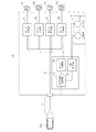
図1に、本発明の第1実施形態に係る電力供給装置1Aを示す。電力供給装置1Aは、例えば、可搬性に優れたトランクケースタイプ(伸縮式キャリーバー・キャスター付)の電力供給装置である。
[First Embodiment]
FIG. 1 shows a
電力供給装置1Aは、電源接続部2と、複数(本実施形態では、4つ)の負荷接続部3a〜3dと、複数(本実施形態では、4つ)のDC/AC変換部4a〜4dと、制御部5と、操作部6とを備える。操作部6は、DC/AC変換部4a〜4dを起動させるための起動スイッチ7と、DC/AC変換部4a〜4dの動作を停止させるための終了スイッチ8とを含む。
The
電源接続部2は、接続プラグおよびこれに付随するケーブルを含む。電源接続部2は、本発明の「直流電源」に相当する蓄電池が搭載された電気自動車(以下、蓄電池搭載車両)100に接続される。
The
負荷接続部3a〜3dは、それぞれ、少なくとも1つの負荷が接続されるコンセントを含む。負荷接続部3a〜3dからは、それぞれ商用交流電力に相当する1.5kWまでの交流電力が出力される。
Each of the
DC/AC変換部4a〜4dは、それぞれDC/AC変換動作を行うインバータ回路およびインバータ制御回路等を含む。DC/AC変換部4a〜4dは、DC側が電源接続部2に接続され、かつAC側が負荷接続部3a〜3dに1対1で接続される。DC/AC変換部4a〜4dは、電源接続部2から入力された直流電力(蓄電池搭載車両100の放電電力)を交流電力(商用交流電力に相当する交流電力)に変換するDC/AC変換動作を行い、当該交流電力を接続先の負荷接続部3a〜3dに出力する。
The DC /
DC/AC変換部4a〜4dは、異常が発生すると停止状態(交流電力を出力しない状態)になるように構成されている。異常は、外部要因(負荷接続部3a〜3dの過負荷)と、内部要因(例えば、DC/AC変換部4a〜4dの故障)とに大別される。例えば、負荷接続部3aが過負荷になった場合、DC/AC変換部4aが停止状態になる。このとき他に異常が発生していなければ、DC/AC変換部4b〜4dの出力は継続される。
The DC /
DC/AC変換部4a〜4dは、それぞれ所定の周期で自己の状態を診断する。具体的には、DC/AC変換部4a〜4dは、交流電力を出力している場合に自己の状態が出力中状態であると診断し、交流電力を出力していない場合に自己の状態が停止状態であると診断する。DC/AC変換部4a〜4dは、制御部5からの要求があると、自己の状態が出力中状態か停止状態かを示す信号を制御部5に出力する。
The DC /
停止状態になったDC/AC変換部4a〜4dは、停止原因が外部要因(過負荷)か内部要因かを診断する。具体的には、DC/AC変換部4a〜4dは、停止直前の出力電流を記憶しておき、当該出力電流が所定の閾値を超えていた場合、停止原因を外部要因(過負荷)と診断し、当該出力電流が所定の閾値を超えていない場合、停止原因を内部要因と診断する。DC/AC変換部4a〜4dは、制御部5からの要求があると、停止原因が外部要因(過負荷)か内部要因かを示す信号を制御部5に出力する。
The DC /
また、DC/AC変換部4a〜4dは、自己の故障の有無を診断することもできる。例えば、DC/AC変換部4a〜4dは、出力電圧が所定の電圧範囲(例えば、AC100V±10%)から外れている場合、故障ありと診断し、出力電圧が当該所定の電圧範囲内の場合、故障なしと診断する。故障ありと診断したDC/AC変換部4a〜4dは、操作部6の起動スイッチ7が押下されても、DC/AC変換動作を行わない。DC/AC変換部4a〜4dは、制御部5からの要求があると、自己の故障の有無を示す信号を制御部5に出力する。
In addition, the DC /
制御部5は、例えば、マイコンで構成される。制御部5は、車両通信制御部5aと、DC/AC制御部5bと、状態判定部5cと、を含む。車両通信制御部5a、DC/AC制御部5bおよび状態判定部5cは、互いに情報を共有する。
The
車両通信制御部5aは、電源接続部2を介して蓄電池搭載車両100と通信を行い、蓄電池搭載車両100から情報(例えば、蓄電池搭載車両100の蓄電池の残量、蓄電池搭載車両100と電源接続部2の接続状態)を取得する。
The vehicle
DC/AC制御部5bは、DC/AC変換部4a〜4dと通信を行い、DC/AC変換部4a〜4dを起動させたり、DC/AC変換部4a〜4dから情報(例えば、DC/AC変換部4a〜4dの状態、停止原因、故障の有無)を取得したりする。起動したDC/AC変換部4a〜4dは、DC/AC変換動作を行う。
The DC /
状態判定部5cは、蓄電池搭載車両100からの情報、DC/AC変換部4a〜4dからの情報、および操作部6からの情報(例えば、起動スイッチ7の状態、終了スイッチ8の状態)に基づいて、電力供給装置1Aの状態を判定する。
The
例えば、電力供給装置1Aに電源電力(DC/AC変換部4a〜4dや制御部5等を動作させるための待機電力)が供給された状態で、起動スイッチ7が押下され、かつ車両通信制御部5aが蓄電池搭載車両100と通信を開始していない場合、状態判定部5cは、電力供給装置1Aの状態を「待機中」(本発明の「第1状態」に相当)と判定する。
For example, the start switch 7 is pressed and the vehicle communication control unit is in a state where the power supply power (standby power for operating the DC /
また、DC/AC変換部4a〜4dの少なくとも1つがDC/AC変換動作を行っている場合、状態判定部5cは、電力供給装置1Aの状態を「放電中」(本発明の「第2状態」に相当)と判定する。DC/AC制御部5bの故障等により、負荷接続部3a〜3dに接続された負荷に対して電力供給が不可能な場合、状態判定部5cは、電力供給装置1Aの状態を「故障中」(本発明の「第3状態」に相当)と判定する。
Further, when at least one of the DC /
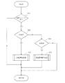
次に、図2および図3を参照して、制御部5(特に、DC/AC制御部5b)の放電制御処理について説明する。
Next, the discharge control process of the control unit 5 (particularly, the DC /
制御部5は、電力供給装置1Aに電源電力が供給されると、図2に示す放電制御処理を開始する。放電制御処理の開始後、状態判定部5cは、起動スイッチ7が押下されたか否かを判定する(S01)。ユーザによって起動スイッチ7が押下されると、状態判定部5cは起動スイッチ7が押下されたと判定する(S01でYES)。
When the power supply power is supplied to the
次いで、状態判定部5cは、電力供給装置1Aの状態が「待機中」か否かを判定する(S02)。状態判定部5は、車両通信制御部5aが蓄電池搭載車両100と通信を開始していない場合は、電力供給装置1Aの状態を「待機中」と判定する(S02でYES)。
Next, the
S02の判定において「待機中」と判定されると、DC/AC制御部5bは、放電開始処理を実行する(S03)。放電開始処理を実行したDC/AC制御部5bは、DC/AC変換部4a〜4dを起動させる。DC/AC変換部4a〜4dは、制御部5の制御に基づき蓄電池搭載車両100を放電させ、蓄電池搭載車両100の直流電力を交流電力に変換して、負荷接続部3a〜3dに接続された負荷に交流電力を供給する。このとき状態判定部5cは、電力供給装置1Aの状態を「放電中」と判定する。
If it is determined to be "waiting" in the determination of S02, the DC /
一方、S02の判定において待機中ではない(S02でNO)と判定されると、状態判定部5cは、電力供給装置1Aの状態が「放電中」か否かを判定する(S04)。状態判定部5cは、DC/AC変換部4a〜4dの少なくとも1つがDC/AC変換動作を行っている場合は、電力供給装置1Aの状態を「放電中」と判定する(S04でYES)。
On the other hand, if it is determined in the determination of S02 that the
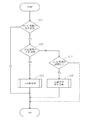
S04の判定において「放電中」と判定されると、DC/AC制御部5bは、再起動確認処理を実行する(S05)。図3に、再起動確認処理のフローチャートを示す。DC/AC制御部5bは、DC/AC変換部4a〜4dのそれぞれに対して再起動確認処理を行う。以下、DC/AC変換部4dに対する再起動確認処理について説明する。
If it is determined in the determination of S04 that "discharging", the DC /
DC/AC制御部5bは、DC/AC変換部4dを参照して、DC/AC変換部4dの状態が停止状態か否かを判定する(S11)。DC/AC変換部4dが自己の状態を停止状態であると診断している場合、DC/AC制御部5bは、DC/AC変換部4dの状態を停止状態と判定する(S11でYES)。S11の判定は、本発明の「第1処理」に相当する。
The DC /
次いで、DC/AC制御部5bは、DC/AC変換部4dを参照して、DC/AC変換部4dの停止原因が外部要因(過負荷)か内部要因かを判定する(S12)。DC/AC変換部4dが自己の停止原因を外部要因(過負荷)であると診断している場合、DC/AC制御部5bは、DC/AC変換部4dの停止原因を外部要因(過負荷)と判定する(S12でYES)。S12の判定は、本発明の「第2処理」に相当する。
Next, the DC /
S12の判定においてDC/AC変換部4dの停止原因を外部要因(過負荷)と判定したDC/AC制御部5bは、DC/AC変換部4dに対して再起動処理を行う(S13)。例えば、このときDC/AC変換部4a〜4cが出力中状態である場合、DC/AC制御部5bは、出力中のDC/AC変換部4a〜4cを停止させることなく(DC/AC変換部4a〜4cの出力を継続させた状態で)、DC/AC変換部4dを再起動させる。これにより、負荷接続部3a〜3cに接続された負荷に対する電力供給が途切れることなく、負荷接続部3dに接続された負荷に対する電力供給が再開される。S13の再起動処理は、本発明の「第3処理」に相当する。
The DC /
一方、S12の判定において、DC/AC変換部4dが自己の停止原因を内部要因と診断している場合、DC/AC制御部5bは、DC/AC変換部4dの停止原因を内部要因と判定する(S12でNO)。次いで、DC/AC制御部5bは、DC/AC変換部4dを参照して、故障ありか故障なしかを判定する(S14)。
On the other hand, in the determination of S12, when the DC /
DC/AC変換部4dが故障ありと診断している場合、DC/AC制御部5bは、DC/AC変換部4dに故障ありと判定し(S14でYES)、起動不可通知処理を実行する(S15)。起動不可通知処理において、DC/AC制御部5bは、DC/AC変換部4dが故障中であることを記憶し、ユーザに対する通知手段がある場合には当該通知手段によりDC/AC変換部4dが故障中であることをユーザに知らせる。
When the DC /
結局、電力供給装置1Aによれば、出力中のDC/AC変換部(例えば、4a〜4c)を停止させることなく、停止状態のDC/AC変換部(例えば、4d)を再起動させる再起動確認処理を実行するので、従来の電力供給装置よりも利便性を高めることができる。なお、再起動確認処理は、DC/AC変換部4a〜4dに対して同時に実行してもよいし、順次実行しても良い。
After all, according to the
[第2実施形態]
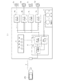
図4に、本発明の第2実施形態に係る電力供給装置1Bを示す。電力供給装置1Bは、第1実施形態に係る電力供給装置1Aに、状態表示部9を追加したものである。
[Second Embodiment]
FIG. 4 shows the
状態表示部9は、複数(本実施形態では、4つ)の状態表示手段9a〜9dを含む。状態表示手段9a〜9dは、DC/AC制御部5bの制御下で自己の状態を変化させる(例えば、点灯、消灯、または点滅する)。状態表示手段9a〜9dは、例えば、LEDで構成される。
The status display unit 9 includes a plurality of (four in this embodiment) status display means 9a to 9d. The state display means 9a to 9d change their own state under the control of the DC /
DC/AC変換部4a、4bが出力中状態、DC/AC変換部4cが過負荷による停止状態、DC/AC変換部4dが故障中で停止状態の場合、例えば、状態表示手段9a、9bが点灯し、状態表示手段9cが消灯し、状態表示手段9dが点滅してもよい。これにより、ユーザはDC/AC変換部4a〜4dの状態を知ることができる。
When the DC /
[第3実施形態]
図5に、本発明の第3実施形態に係る電力供給装置1Cを示す。電力供給装置1Cは、第1実施形態に係る電力供給装置1Aの操作部6の変わりに、操作部6’を追加したものである。
[Third Embodiment]
FIG. 5 shows the
操作部6’は、DC/AC変換部4aを起動させるための起動スイッチ7aと、DC/AC変換部4bを起動させるための起動スイッチ7bと、DC/AC変換部4cを起動させるための起動スイッチ7cと、DC/AC変換部4dを起動させるための起動スイッチ7dと、DC/AC変換部4a〜4dの動作を停止させるための終了スイッチ8とを含む。
The operation unit 6'has an
本実施形態では、状態判定部5cは、放電制御処理のS01の判定において、起動スイッチ7a〜7dの少なくとも1つが押下されたか否かを判定する。また、DC/AC制御部5bは、S03の放電開始処理およびS05の再起動確認処理を、押下された起動スイッチ7a〜7dに対応するDC/AC変換部4a〜4dに対して実行する。
In the present embodiment, the
以上、本発明に係る電力供給装置の実施形態について説明したが、本発明は上記各実施形態に限定されるものではない。 Although the embodiment of the power supply device according to the present invention has been described above, the present invention is not limited to each of the above embodiments.
本発明に係る電力供給装置は、複数の電源接続部2を備えていてもよい。電源接続部2は、直流電源に接続されるように構成されていればよい。電源接続部2が接続される直流電源は、蓄電池搭載車両100以外のものでもよい。
The power supply device according to the present invention may include a plurality of power
本発明に係る負荷接続部は、少なくとも2つあればよい。同様に、本発明に係るDC/AC変換部は、少なくとも2つあればよい。本発明に係るDC/AC変換部は、DC/AC変換動作を行い、接続先の負荷接続部が過負荷になると停止状態になるのであれば、適宜構成を変更することができる。 There may be at least two load connection portions according to the present invention. Similarly, there may be at least two DC / AC converters according to the present invention. The DC / AC conversion unit according to the present invention performs a DC / AC conversion operation, and if the load connection unit at the connection destination is in a stopped state when the load is overloaded, the configuration can be appropriately changed.
本発明に係るDC/AC変換部は、自己の状態、停止原因、故障の有無を診断しなくても良い。この場合、制御部5に、DC/AC変換部の状態、停止原因、故障の有無を直接判定させてもよい。
The DC / AC converter according to the present invention does not have to diagnose its own state, the cause of stoppage, and the presence or absence of failure. In this case, the
本発明に係る制御部は、複数のDC/AC変換部のうち、DC/AC変換動作を行っている出力中のDC/AC変換部を停止させることなく、停止状態のDC/AC変換部を再起動させる再起動確認処理を実行するのであれば、適宜構成を変更することができる。 The control unit according to the present invention can perform a DC / AC conversion unit in a stopped state without stopping the DC / AC conversion unit during output that is performing a DC / AC conversion operation among a plurality of DC / AC conversion units. If the restart confirmation process for restarting is executed, the configuration can be changed as appropriate.
DC/AC変換部4a〜4dが過負荷で停止状態になった場合、所定期間(例えば、再起動確認処理が1回または複数回行われるまで)、ユーザによって起動スイッチ7が押下されていなくても、状態判定部5cは起動スイッチ7が押下されたと判定してもよい。これにより、再起動確認処理が自動的に実行されるので、利便性がより向上する。なお、再起動確認処理を自動的に実行する場合、上記の所定期間が経過したことをユーザに通知する通知手段を設けることが好ましい。
When the DC /
1A〜1C 電力供給装置
2 電源接続部
3a〜3d 負荷接続部
4a〜4d DC/AC変換部
5 制御部
5a 車両通信制御部
5b DC/AC制御部
5c 状態判定部
6、6’ 操作部
7、7a〜7d 起動スイッチ
8 終了スイッチ
9 状態表示部
9a〜9d 状態表示手段
1A to 1C
Claims (5)
負荷が接続される複数の負荷接続部と、
DC側が前記電源接続部に接続され、かつAC側が前記複数の負荷接続部に1対1で接続された複数のDC/AC変換部と、
前記複数のDC/AC変換部を起動させる制御部と、を備え、
前記負荷接続部が過負荷になると当該負荷接続部に接続されたDC/AC変換部が停止状態になる電力供給装置であって、
前記制御部は、
前記複数のDC/AC変換部のうち、DC/AC変換動作を行っている出力中のDC/AC変換部を停止させることなく、前記停止状態のDC/AC変換部を再起動させる再起動確認処理を実行する
ことを特徴とする電力供給装置。 Power connection part connected to DC power supply and
Multiple load connections to which loads are connected,
A plurality of DC / AC conversion units whose DC side is connected to the power supply connection unit and whose AC side is connected to the plurality of load connection units on a one-to-one basis.
A control unit for activating the plurality of DC / AC conversion units is provided.
A power supply device in which the DC / AC conversion unit connected to the load connection unit is stopped when the load connection unit is overloaded.
The control unit
Restart confirmation to restart the stopped DC / AC conversion unit without stopping the output DC / AC conversion unit that is performing the DC / AC conversion operation among the plurality of DC / AC conversion units. A power supply device characterized by performing processing.
前記複数のDC/AC変換部に前記停止状態のDC/AC変換部があるか否かを判定する第1処理と、
前記停止状態のDC/AC変換部の停止原因が過負荷か否かを判定する第2処理と、
前記第1処理において前記停止状態のDC/AC変換部があると判定し、かつ前記第2処理において停止原因が過負荷であると判定した場合に、前記停止状態のDC/AC変換部を再起動させる第3処理と、を含む
ことを特徴とする請求項1に記載の電力供給装置。 The restart confirmation process is
The first process of determining whether or not the plurality of DC / AC conversion units have the stopped DC / AC conversion unit, and
The second process of determining whether or not the cause of the stop of the DC / AC conversion unit in the stopped state is an overload, and
When it is determined in the first process that there is a DC / AC conversion unit in the stopped state and it is determined in the second process that the cause of the stop is an overload, the DC / AC conversion unit in the stopped state is restarted. The power supply device according to claim 1, further comprising a third process of activating.
前記制御部は、前記停止状態のDC/AC変換部の停止直前の出力電流値が所定の閾値を超えていた場合に、停止原因が過負荷であると判定する
ことを特徴とする請求項2に記載の電力供給装置。 In the second process
2. The control unit is characterized in that when the output current value immediately before the stop of the DC / AC conversion unit in the stopped state exceeds a predetermined threshold value, the control unit determines that the cause of the stop is an overload. The power supply device described in.
前記複数のDC/AC変換部に前記出力中のDC/AC変換部があるか否かを判定し、前記出力中のDC/AC変換部があると判定した場合に前記再起動確認処理を実行する
ことを特徴とする請求項1〜3のいずれか一項に記載の電力供給装置。 The control unit
It is determined whether or not the plurality of DC / AC conversion units have the DC / AC conversion unit in the output, and when it is determined that the DC / AC conversion unit in the output is present, the restart confirmation process is executed. The power supply device according to any one of claims 1 to 3, wherein the power supply device is characterized by the above.
前記直流電源である蓄電池搭載車両との通信を行う車両通信制御部と、
前記複数のDC/AC変換部を起動させるDC/AC制御部と、
前記車両通信制御部による前記蓄電池搭載車両との通信がなく、かつ前記複数のDC/AC変換部が起動可能な第1状態か、前記複数のDC/AC変換部に前記出力中のDC/AC変換部がある第2状態か、前記複数のDC/AC変換部が起動不可能な第3状態か、を判定する状態判定部と、を備える
ことを特徴とする請求項1〜4のいずれか一項に記載の電力供給装置。 The control unit
A vehicle communication control unit that communicates with a vehicle equipped with a storage battery, which is a DC power source,
A DC / AC control unit that activates the plurality of DC / AC conversion units,
The first state in which the vehicle communication control unit does not communicate with the storage battery-equipped vehicle and the plurality of DC / AC conversion units can be activated, or the DC / AC being output to the plurality of DC / AC conversion units. One of claims 1 to 4, wherein a state determination unit for determining whether the conversion unit is in a second state or the plurality of DC / AC conversion units cannot be started is provided. The power supply device according to paragraph 1.
Priority Applications (1)
| Application Number | Priority Date | Filing Date | Title |
|---|---|---|---|
| JP2017123464A JP6777595B2 (en) | 2017-06-23 | 2017-06-23 | Power supply device |
Applications Claiming Priority (1)
| Application Number | Priority Date | Filing Date | Title |
|---|---|---|---|
| JP2017123464A JP6777595B2 (en) | 2017-06-23 | 2017-06-23 | Power supply device |
Publications (2)
| Publication Number | Publication Date |
|---|---|
| JP2019009896A JP2019009896A (en) | 2019-01-17 |
| JP6777595B2 true JP6777595B2 (en) | 2020-10-28 |
Family
ID=65029188
Family Applications (1)
| Application Number | Title | Priority Date | Filing Date |
|---|---|---|---|
| JP2017123464A Active JP6777595B2 (en) | 2017-06-23 | 2017-06-23 | Power supply device |
Country Status (1)
| Country | Link |
|---|---|
| JP (1) | JP6777595B2 (en) |
Family Cites Families (6)
| Publication number | Priority date | Publication date | Assignee | Title |
|---|---|---|---|---|
| JPH01129778A (en) * | 1987-11-13 | 1989-05-23 | Mitsubishi Electric Corp | Protecting circuit for inverter |
| US5416689A (en) * | 1992-12-17 | 1995-05-16 | Digital Equipment Corporation | Current mode switching power supply overload protection circuit with false fault condition screening |
| JP3250354B2 (en) * | 1993-12-24 | 2002-01-28 | オムロン株式会社 | Power supply |
| JP2013183520A (en) * | 2012-03-01 | 2013-09-12 | Honda Motor Co Ltd | Electric vehicle capable of external power supply and charging |
| JP6271970B2 (en) * | 2013-11-27 | 2018-01-31 | 株式会社ダイヘン | Power conditioner and storage method |
| CN106026628B (en) * | 2016-06-30 | 2018-07-10 | 江苏国网自控科技股份有限公司 | A kind of reset locking-type frequency converter resumption control method and device |
-
2017
- 2017-06-23 JP JP2017123464A patent/JP6777595B2/en active Active
Also Published As
| Publication number | Publication date |
|---|---|
| JP2019009896A (en) | 2019-01-17 |
Similar Documents
| Publication | Publication Date | Title |
|---|---|---|
| CN110182097B (en) | Vehicle power supply system | |
| JP6831281B2 (en) | Battery monitoring system and battery monitoring device | |
| WO2017179162A1 (en) | Uninterruptible power source device | |
| JP7068458B2 (en) | Conveyor control device | |
| CN110382282A (en) | Vehicle power-supply unit | |
| CN104025414A (en) | power storage device | |
| JP6704521B2 (en) | Passenger conveyor | |
| JP5392338B2 (en) | Battery monitoring device | |
| JP2014110666A (en) | Discharge control system, and discharge device | |
| JP2016126645A (en) | Power supply device and program for storing logs | |
| JP2006060963A (en) | Uninterruptible power supply system | |
| JP4406931B2 (en) | Power system | |
| JP2013258827A (en) | Uninterruptible power supply system | |
| JP5930794B2 (en) | Starter drive | |
| JP7278800B2 (en) | power supply system | |
| JP5533608B2 (en) | Battery monitoring device | |
| JP2019009896A (en) | Power supply equipment | |
| JP6175815B2 (en) | Multiple power supply apparatus, control method for multiple power supply apparatus, and program | |
| JP7455737B2 (en) | Power supply system and power supply system control method | |
| JP2002176736A (en) | Uninterruptible power supply system | |
| JP5012741B2 (en) | Power supply device, power supply method, power supply control program, and power supply system | |
| JP2017041919A (en) | Power conversion system | |
| CN116653902B (en) | Vehicle-mounted system and vehicle | |
| JP6886040B2 (en) | Power supply system | |
| JP4013961B2 (en) | Power supply control device for electronic equipment |
Legal Events
| Date | Code | Title | Description |
|---|---|---|---|
| A621 | Written request for application examination |
Free format text: JAPANESE INTERMEDIATE CODE: A621 Effective date: 20191212 |
|
| A977 | Report on retrieval |
Free format text: JAPANESE INTERMEDIATE CODE: A971007 Effective date: 20200924 |
|
| TRDD | Decision of grant or rejection written | ||
| A01 | Written decision to grant a patent or to grant a registration (utility model) |
Free format text: JAPANESE INTERMEDIATE CODE: A01 Effective date: 20201007 |
|
| A61 | First payment of annual fees (during grant procedure) |
Free format text: JAPANESE INTERMEDIATE CODE: A61 Effective date: 20201008 |
|
| R150 | Certificate of patent or registration of utility model |
Ref document number: 6777595 Country of ref document: JP Free format text: JAPANESE INTERMEDIATE CODE: R150 |
|
| R250 | Receipt of annual fees |
Free format text: JAPANESE INTERMEDIATE CODE: R250 |
|
| R250 | Receipt of annual fees |
Free format text: JAPANESE INTERMEDIATE CODE: R250 |
|
| R250 | Receipt of annual fees |
Free format text: JAPANESE INTERMEDIATE CODE: R250 |