JP6777591B2 - Condensed water treatment equipment - Google Patents
Condensed water treatment equipment Download PDFInfo
- Publication number
- JP6777591B2 JP6777591B2 JP2017112745A JP2017112745A JP6777591B2 JP 6777591 B2 JP6777591 B2 JP 6777591B2 JP 2017112745 A JP2017112745 A JP 2017112745A JP 2017112745 A JP2017112745 A JP 2017112745A JP 6777591 B2 JP6777591 B2 JP 6777591B2
- Authority
- JP
- Japan
- Prior art keywords
- passage
- condensed water
- valve
- water treatment
- intercooler
- Prior art date
- Legal status (The legal status is an assumption and is not a legal conclusion. Google has not performed a legal analysis and makes no representation as to the accuracy of the status listed.)
- Expired - Fee Related
Links
Images
Classifications
-
- Y—GENERAL TAGGING OF NEW TECHNOLOGICAL DEVELOPMENTS; GENERAL TAGGING OF CROSS-SECTIONAL TECHNOLOGIES SPANNING OVER SEVERAL SECTIONS OF THE IPC; TECHNICAL SUBJECTS COVERED BY FORMER USPC CROSS-REFERENCE ART COLLECTIONS [XRACs] AND DIGESTS
- Y02—TECHNOLOGIES OR APPLICATIONS FOR MITIGATION OR ADAPTATION AGAINST CLIMATE CHANGE
- Y02T—CLIMATE CHANGE MITIGATION TECHNOLOGIES RELATED TO TRANSPORTATION
- Y02T10/00—Road transport of goods or passengers
- Y02T10/10—Internal combustion engine [ICE] based vehicles
- Y02T10/12—Improving ICE efficiencies
Landscapes
- Supercharger (AREA)
- Exhaust-Gas Circulating Devices (AREA)
Description
本発明は、排気ガスの一部がインタークーラーの上流に還流されるEGR装置を備えたエンジンシステムに搭載される凝縮水処理装置に関する。 The present invention relates to a condensed water treatment device mounted on an engine system including an EGR device in which a part of exhaust gas is returned to the upstream of an intercooler.
従来から、ターボチャージャーを備えたエンジンシステムに関して、排気ガスの一部を吸気側に還流する排気再循環(EGR:Exhaust Gas Recirculation)装置を備えたエンジンシステムが知られている。EGR装置の一例は、タービンを通過した排気ガスの一部をEGRガスとしてコンプレッサーの上流へ還流する。 Conventionally, as for an engine system provided with a turbocharger, an engine system provided with an exhaust gas recirculation (EGR: Exhaust Gas Recirculation) device for returning a part of exhaust gas to the intake side has been known. In an example of the EGR device, a part of the exhaust gas that has passed through the turbine is returned as EGR gas to the upstream of the compressor.
こうしたエンジンシステムでは、EGRガスと空気との混合気体がコンプレッサーによって圧縮され、その後、インタークーラーによって冷却される。そのため、インタークーラーでは、EGRガス中の水分が凝縮した凝縮水が生成される。この凝縮水は、EGRガス中の硫黄成分などが溶解することによって高い腐食性を有する。そのため、特許文献1では、そうした凝縮水をインタークーラーの下流を流れる作動ガスに添加してエンジンに供給することで凝縮水を処理する技術が開示されている。
In such an engine system, a mixture of EGR gas and air is compressed by a compressor and then cooled by an intercooler. Therefore, in the intercooler, condensed water in which the water content in the EGR gas is condensed is generated. This condensed water has high corrosiveness due to the dissolution of sulfur components and the like in the EGR gas. Therefore,
しかしながら、特許文献1では、インタークーラーで生成された凝縮水が直ちに作動ガスに添加される。そのため、凝縮水を効果的に処理するうえで改善の余地がある。
本発明は、インタークーラーにて生成される凝縮水の処理を効果的に行うことができる凝縮水処理装置を提供することを目的とする。
However, in
An object of the present invention is to provide a condensed water treatment apparatus capable of effectively treating condensed water generated by an intercooler.
上記課題を解決する凝縮水処理装置は、エンジンの吸気通路に配設されたインタークーラーと、排気ガスの一部を前記吸気通路における前記インタークーラーの上流に還流するEGR装置と、を備えたエンジンシステムに搭載される凝縮水処理装置であって、前記インタークーラーに接続された流入通路を通じて前記インタークーラー内の凝縮水が流入可能に構成された貯留部と、前記貯留部の内部空間に第1導入口を有して前記エンジンと前記インタークーラーとを繋ぐ流通通路に連通する第1通路と、前記第1通路を開閉可能に構成された第1バルブと、前記貯留部の内部空間において前記第1導入口よりも上方に位置する第2導入口を有して前記流通通路に連通する第2通路と、前記貯留部における前記凝縮水の水位が所定値に到達すると前記第2通路を閉鎖する第2バルブと、前記第1バルブの開閉を制御する制御部と、を備える。 The condensed water treatment device for solving the above problems is an engine system including an intercooler arranged in the intake passage of the engine and an EGR device for returning a part of exhaust gas to the upstream of the intercooler in the intake passage. It is a condensate water treatment device to be mounted, and has a storage unit configured so that condensed water in the intercooler can flow in through an inflow passage connected to the intercooler, and a first introduction port in the internal space of the storage unit. A first passage communicating with the flow passage connecting the engine and the intercooler, a first valve configured to open and close the first passage, and a first inlet in the internal space of the storage portion. A second passage having a second introduction port located above and communicating with the flow passage, and a second valve that closes the second passage when the water level of the condensed water in the storage portion reaches a predetermined value. A control unit for controlling the opening and closing of the first valve is provided.
上記構成によれば、流通通路を流れるガスによるベンチュリ効果によって、第1バルブが閉状態にあるときには第2通路を通じて貯留部内のガスをエンジンに供給することが可能であり、第1バルブが開状態にあるときには第1通路を通じて貯留部内の凝縮水をエンジンに供給することが可能である。そして、エンジンへの凝縮水あるいはガスの供給により貯留部内の圧力が低下するため、流入通路を通じてインタークーラー内の凝縮水が貯留部に吸い上げられる。すなわち、上記構成の凝縮水処理装置は、第1バルブの開閉にかかわらず第2バルブが閉弁するまでインタークーラー内の凝縮水が流入通路を通じて貯留部に吸い上げられ続ける構成となっている。そして、制御部による第1バルブの開閉の制御によって凝縮水をエンジンに供給するタイミングを制御することが可能である。すなわち、上記構成によれば、凝縮水を貯留しつつエンジンに凝縮水を供給するタイミングが制御可能であることから、凝縮水の処理を効果的に行うことができる。 According to the above configuration, due to the venturi effect of the gas flowing through the flow passage, when the first valve is in the closed state, the gas in the storage portion can be supplied to the engine through the second passage, and the first valve is in the open state. It is possible to supply the condensed water in the reservoir to the engine through the first passage. Then, since the pressure in the storage section is reduced by supplying the condensed water or gas to the engine, the condensed water in the intercooler is sucked up into the storage section through the inflow passage. That is, the condensed water treatment device having the above configuration has a configuration in which the condensed water in the intercooler continues to be sucked into the storage portion through the inflow passage until the second valve is closed regardless of whether the first valve is opened or closed. Then, it is possible to control the timing of supplying the condensed water to the engine by controlling the opening and closing of the first valve by the control unit. That is, according to the above configuration, since the timing of supplying the condensed water to the engine while storing the condensed water can be controlled, the treatment of the condensed water can be effectively performed.
上記凝縮水処理装置において、前記第2バルブがフロートバルブであるとよい。
上記構成によれば、凝縮水の水位が所定値に到達すると第2バルブが自動で閉弁するため、第2バルブの構成のみならず凝縮水処理装置の構成を簡素化することができる。
In the condensed water treatment apparatus, the second valve may be a float valve.
According to the above configuration, the second valve automatically closes when the water level of the condensed water reaches a predetermined value, so that not only the configuration of the second valve but also the configuration of the condensed water treatment device can be simplified.
上記凝縮水処理装置において、前記第1通路および前記第2通路は、共通の通路を通じて前記流通通路に連通していることが好ましい。
上記構成によれば、第1通路と第2通路とが各別に流通通路に対して連通する構成に比べて配管の複雑化を抑えることができる。
In the condensed water treatment apparatus, it is preferable that the first passage and the second passage communicate with the distribution passage through a common passage.
According to the above configuration, it is possible to suppress the complexity of the piping as compared with the configuration in which the first passage and the second passage communicate with the distribution passage separately.
上記凝縮水処理装置において、前記流通通路は、複数のシリンダーの各々に対応する吸気ポートを有しており、前記第1通路および前記第2通路は、前記吸気ポートの各々に連通していることが好ましい。
上記構成によれば、凝縮水が各吸気ポートに供給されるため、各シリンダーに供給される凝縮水量の均一化を図ることができる。
In the condensed water treatment apparatus, the flow passage has an intake port corresponding to each of a plurality of cylinders, and the first passage and the second passage communicate with each of the intake ports. Is preferable.
According to the above configuration, since the condensed water is supplied to each intake port, the amount of condensed water supplied to each cylinder can be made uniform.
上記凝縮水処理装置において、前記制御部は、前記エンジンの運転状態に関する情報を取得し、前記取得した情報に基づく前記運転状態が高負荷状態であるときに前記第1バルブを開状態に制御することが好ましい。 In the condensed water treatment device, the control unit acquires information on the operating state of the engine and controls the first valve to be in the open state when the operating state based on the acquired information is a high load state. Is preferable.
上記構成によれば、高負荷状態にあるエンジンに対して凝縮水が供給されることから、筒内圧力の過度な上昇を抑えることができる。 According to the above configuration, since the condensed water is supplied to the engine in the high load state, it is possible to suppress an excessive increase in the in-cylinder pressure.
図1〜図5を参照して凝縮水処理装置の一実施形態について説明する。まず、図1を参照して凝縮水処理装置を搭載したエンジンシステムの概要について説明する。
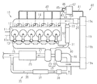
図1に示すように、エンジンシステムは、エンジン10を備えている。エンジン10のシリンダーブロック11には複数のシリンダー12が形成されている。各シリンダー12においては、吸入した作動ガスに対してインジェクター13から燃料が噴射され、作動ガスと燃料との混合気が燃焼する。こうした混合気の燃焼が所定の順番で各シリンダー12において行われることにより、エンジン10のクランクシャフト10aが駆動される。
An embodiment of the condensed water treatment apparatus will be described with reference to FIGS. 1 to 5. First, an outline of an engine system equipped with a condensed water treatment device will be described with reference to FIG.
As shown in FIG. 1, the engine system includes an
シリンダーブロック11には、各シリンダー12に作動ガスを分配するインテークマニホールド14と、各シリンダー12から排気ガスが排出されるエキゾーストマニホールド15とが接続されている。インテークマニホールド14に接続される吸気通路16は、上流側から順に図示されないエアクリーナー、ターボチャージャー17のコンプレッサー18、インタークーラー19を備えている。コンプレッサー18で圧縮された作動ガスは、インタークーラー19の上流側タンク19aに流入したのちコア部19bにて冷却され、下流側タンク19cを通じてインタークーラー19から流出する。吸気通路16は、インタークーラー19の下流であって、かつ、後述する高圧EGR通路31の合流部分よりも上流に、吸気通路16の流路断面積を変更可能なスロットル20を備えている。エンジン10とインタークーラー19とを繋ぐ流通通路16Aは、作動ガスが流通する通路であり、吸気通路16におけるインタークーラー19よりも下流の部分と、インテークマニホールド14とによって構成される。エキゾーストマニホールド15に接続される排気通路21は、コンプレッサー18にタービンシャフトを介して連結されたタービン23と、タービン23を通過した排気ガスを浄化する排気浄化装置25とを備えている。
The cylinder block 11 is connected to an
エンジンシステムは、高圧EGR(Exhaust Gas Recirculation)装置30と低圧EGR装置35とを備えている。
高圧EGR装置30は、タービン23を通過するまえの排気ガスの一部を高圧EGRガスとして吸気通路16におけるスロットル20の下流に還流する。高圧EGR装置30は、高圧EGR通路31と、高圧EGRクーラー32と、高圧EGR弁33とを有している。高圧EGR通路31は、エキゾーストマニホールド15と吸気通路16におけるスロットル20の下流とを接続する。高圧EGRクーラー32は、高圧EGR通路31に配設されており、高圧EGRガスを冷却することにより高圧EGRガスの密度を高める。高圧EGR弁33は、高圧EGR通路31における高圧EGRクーラー32の下流に配設されており、高圧EGR通路31の流路断面積を変更可能に構成されている。高圧EGR装置30は、例えば、エンジン10に対するドライバーの要求負荷が高負荷であるときに作動状態に制御される。
The engine system includes a high-pressure EGR (Exhaust Gas Recirculation)
The high-
低圧EGR装置35は、タービン23および排気浄化装置25を通過した排気ガスの一部を低圧EGRガスとしてコンプレッサー18の上流に還流する。低圧EGR装置35は、低圧EGR通路36と、低圧EGRクーラー37と、低圧EGR弁38とを有している。低圧EGR通路36は、排気通路21における排気浄化装置25の下流と吸気通路16におけるコンプレッサー18の上流とを接続する。低圧EGRクーラー37は、低圧EGR通路36に配設されており、低圧EGRガスを冷却することにより低圧EGRガスの密度を高める。低圧EGR弁38は、低圧EGR通路36における低圧EGRクーラー37の下流に配設されており、低圧EGR通路36の流路断面積を変更可能に構成されている。低圧EGR装置35は、例えば、エンジン10に対するドライバーの要求負荷が低負荷あるいは中負荷であるときに作動状態に制御される。
The low-
低圧EGR装置35の作動中、インタークーラー19においては、低圧EGRガスと空気との混合気体が作動ガスとして流通する。そのため、インタークーラー19においては、低圧EGRガス中の水蒸気が凝縮し、その凝縮した水分に低圧EGRガス中の硫黄成分や未燃燃料成分が溶解することにより高い腐食性を有する凝縮水が生成される。エンジンシステムは、凝縮水を処理する凝縮水処理装置40を備えている。
During the operation of the low-
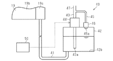
図2〜図5を参照して凝縮水処理装置40について説明する。図2に示すように、凝縮水処理装置40は、流入通路41、貯留部42、第1通路43、第1バルブ44、第2通路45、第2バルブ46、および、共通通路47を有している。
The condensed
流入通路41は、凝縮水による腐食に対する耐性が高い材料、例えばステンレスなどの高耐食性材料を中心に構成される。流入通路41は、インタークーラー19と貯留部42とを接続している。流入通路41は、インタークーラー19で生成された凝縮水が流入しやすいように、インタークーラー19に対して下流側タンク19cの底部に接続されている。また、流入通路41は、貯留部42に対して貯留部42の底部に接続されており、貯留部42の底面42bに開口している。
The
貯留部42は、流入通路41を通じて流入した凝縮水を貯留する。貯留部42は、例えばステンレスなどの高耐食性材料を中心に構成される。貯留部42には、第1通路43と第2通路45とが接続されている。貯留部42は、流入通路41、第1通路43、および、第2通路45が接続された密閉容器である。第1通路43および第2通路45は、共通通路47に接続されている。
The
第1通路43は、貯留部42の内部空間における底面42b寄りに第1導入口43aを有している。第1通路43は、第1導入口43aから上方に向かって延びており、貯留部42の頂部を貫通している。第1通路43は、貯留部42の外部で共通通路47に接続されている。第1通路43には、貯留部42の外部に、制御装置50によって制御される電子制御式の第1バルブ44が配設されている。第1バルブ44は、第1通路43の流路断面積を変更可能に構成されており、例えば、第1通路43を開閉するノーマリークローズ型の電磁弁である。すなわち、第1バルブ44が開状態にあるとき、貯留部42の内部空間は、第1通路43を通じて共通通路47に連通する。第1通路43および第1バルブ44は、例えばステンレスなどの高耐食性材料を中心に構成される。
The
第2通路45は、貯留部42の内部空間における第1導入口43aよりも上方に第2導入口45aを有しており、その下流端が第1通路43と共通通路47との接続部分に接続されている。第2通路45は、第1通路43よりも流路抵抗が大きい通路であり、例えば、第1通路43よりも小さい流路断面積が連続する通路である。第2通路45には、第2バルブ46が配設されている。第2バルブ46は、貯留部42における水位が所定値(満水)に到達すると閉弁するように構成されており、例えば、浮力により弁体が移動するフロートバルブである。すなわち、凝縮水の水位が所定値未満であり第2バルブ46が開状態にあるとき、貯留部42の内部空間は、第2通路45を通じて共通通路47に連通する。これら第2通路45および第2バルブ46は、例えばステンレスなどの高耐食性材料を中心に構成される。
The
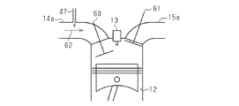
図3に示すように、流通通路16Aを構成するインテークマニホールド14は、各シリンダー12に対応する吸気ポート14aを有している。吸気ポート14aは、吸気バルブ60によって開閉される。また、エキゾーストマニホールド15は、各シリンダー12に対応する排気ポート15aを有している。排気ポート15aは、排気バルブ61によって開閉される。そして、共通通路47は、例えばステンレスなどの高耐食性材料を中心に構成されており、インテークマニホールド14の各吸気ポート14aに対して接続されている。すなわち、第1通路43および第2通路45は、共通通路47を通じて流通通路16Aの一部である各吸気ポート14aに連通している。共通通路47は、吸気バルブ60が開状態(吸気行程)にあるシリンダー12に対応する吸気ポート14aを流れる作動ガス62のベンチュリ効果により、貯留部42内の凝縮水や貯留部42内のガス(以下、貯留部42内のガスを貯留ガスという。)を吸気ポート14aに供給する。
As shown in FIG. 3, the
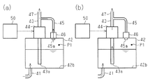
例えば、図4(a)に示すように、凝縮水の水位が第1導入口43aよりも高く、かつ、第1バルブ44が閉状態、第2バルブ46が開状態にあるとき、共通通路47は、第2通路45から流入してくる貯留部42内の貯留ガスを各吸気ポート14aに供給する。また例えば、図4(b)に示すように、凝縮水の水位が第1導入口43aよりも高く、かつ、第1バルブ44が開状態にあるとき、共通通路47は、第2バルブ46の開閉にかかわらず、第1通路43から流入してくる貯留部42内の凝縮水を各吸気ポート14aに供給する。そして、図4(a)および図4(b)に示すように、各吸気ポート14aに対する貯留ガスの供給あるいは凝縮水の供給によって貯留部42の圧力P1が低下する。この圧力P1の低下により、流入通路41を通じてインタークーラー19内の凝縮水が貯留部42へと吸い上げられることとなる。すなわち、凝縮水処理装置40においては、第1バルブ44および第2バルブ46の双方が閉状態にあるときを除き、インタークーラー19内の凝縮水が流入通路41を通じて貯留部42に吸い上げられ続ける構成となっている。
For example, as shown in FIG. 4A, when the water level of the condensed water is higher than that of the first introduction port 43a, the
このように凝縮水処理装置40は、貯留部42に貯留された凝縮水を各吸気ポート14aに供給することにより凝縮水を処理する。凝縮水は、作動ガスとともにエンジン10の各シリンダー12に導入されたのち、排気ガスの一部として排気ポート15aに排出される。凝縮水は、作動ガスの比熱比を低下させるとともに、吸熱により作動ガスの温度を低下させることにより密度を増大させ、シリンダー12に導入される作動ガスを増量させる。シリンダー12に導入された凝縮水は、混合気の燃焼時に燃焼熱の一部を吸熱することにより燃焼温度を低下させる。凝縮水は、こうした作動ガスの比熱比の低下、作動ガスの増量、および、燃焼温度の低下により、燃焼時におけるシリンダー12内の圧力である筒内圧力を低下させる。凝縮水は、燃料噴射量や吸入空気量など、同じ燃焼条件のもとでは温度が低いほど燃焼温度および筒内圧力を低下させる。
In this way, the condensed
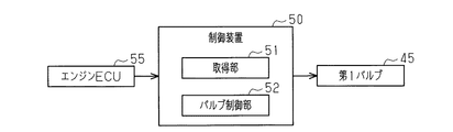
図5に示すように、凝縮水処理装置40は、第1バルブ44を制御対象とする制御装置50を備えている。制御装置50は、プロセッサ、メモリー、入力インターフェース、および、出力インターフェース等がバスを介して互いに接続された1以上のマイクロコンピューターを中心に構成される。制御装置50は、入力インターフェースを介して取得した各種情報、ならびに、メモリーに格納された各種制御プログラムおよび各種データに基づいて各種処理を実行する。制御装置50は、各種処理の結果に基づく制御信号を出力インターフェースを介して制御対象に出力する。
As shown in FIG. 5, the condensed
制御装置50は、各種機能部として、エンジン10の運転状態に関する情報を取得する取得部51と、第1バルブ44の開閉を制御するバルブ制御部52とを有している。
取得部51は、上記情報として、例えば、エンジン10を制御するエンジンECU55からの制御信号を通じて燃料噴射量Gfを取得する。バルブ制御部52は、取得部51が取得した燃料噴射量Gfがエンジン10の運転状態が高負荷状態にあることを示す高負荷噴射量Gf1以上である場合には第1バルブ44を開状態に制御する。また、バルブ制御部52は、燃料噴射量Gfが上記高負荷噴射量Gf1未満である場合には第1バルブ44を閉状態に制御する。
The
As the above information, the
上記実施形態の凝縮水処理装置40によれば、以下に列挙する作用効果が得られる。
(1)凝縮水処理装置40は、貯留部42における凝縮水の水位、および、第1バルブ44の開閉状態にかかわらず、第2バルブ46が閉弁するまでインタークーラー19内の凝縮水を流入通路41を通じて貯留部42に吸い上げ続ける構成となっている。これにより、インタークーラー19内の凝縮水を貯留部42に効率よく貯留させることができる。そして、制御装置50による第1バルブ44の開閉の制御によって、エンジンに対する凝縮水の供給タイミングが制御可能である。これらのことから、凝縮水の処理を効果的に行うことができる。
According to the condensed
(1) The condensed
(2)第2バルブ46がフロートバルブである。そのため、例えば、貯留部42の水位を計測するレベルセンサー等からの検出信号に基づいて電子制御式の第2バルブ46の開閉を制御しなくとも、凝縮水の水位が所定値に到達すると自動で第2通路45が閉鎖される。そのため、第2バルブ46の構成のみならず、凝縮水処理装置40の構成の簡素化を図ることができる。
(2) The
(3)第1通路43および第2通路45は、共通通路47を通じて各吸気ポート14aに連通している。そのため、第1通路43および第2通路45が各吸気ポート14aに対して各別に連通している構成に比べて配管構成の簡素化を図ることができる。
(3) The
(4)第1通路43および第2通路45が共通通路47を通じて各吸気ポート14aに連通している。これにより、各シリンダー12に供給される凝縮水量の均一化を図ることができる。その結果、高負荷状態にあるエンジン10においてシリンダー12ごとの出力のばらつきを抑えつつ凝縮水を処理することができる。
(4) The
(5)高負荷状態にあるエンジン10においては筒内圧力が高くなるため、シリンダーブロック11などに対する機械的な負荷が大きくなる。この点、制御装置50は、エンジン10が高負荷状態にある場合に第1バルブ44を開状態に制御する。こうした構成によれば、筒内圧力の過度な上昇を抑えることができる。また、凝縮水の供給によって筒内圧力の抑制が図られることから、筒内圧力の抑制のためにエンジン10が吸入する作動ガス量を減らす必要がない。すなわち、高負荷状態にあるエンジン10に供給される空気量が確保されやすくなることから、黒煙の排出量を抑えることができる。また、低負荷状態や中負荷状態にあるエンジン10に対する凝縮水の供給を回避することにより、これらの運転状態における各シリンダー12での燃焼を安定させることができる。
(5) In the
なお、上記実施形態は、以下のように適宜変更して実施することもできる。
・制御装置50は、燃料噴射量Gfに限らず、例えば、エンジン回転数Neやアクセル開度ACC等をエンジン10の運転状態に関する情報として取得し、その取得した情報に基づいてエンジン10の運転状態を判断してもよい。
The above embodiment can be modified as appropriate and implemented as follows.
The
・制御装置50は、エンジン10の運転状態が高負荷状態にあるときに限らず、例えば、エンジン10の運転状態が低中負荷状態にあるときやアイドリング状態にあるときに第1バルブ44を開状態に制御してもよい。
The
・第1通路43および第2通路45は、流通通路16Aに連通していればよく、その連通先は吸気ポート14aに限られない。例えば、第1通路43および第2通路45は、吸気通路16におけるスロットル20の直下流に連通していてもよいし、高圧EGR通路31における高圧EGR弁33の下流を通じて吸気通路16に連通していてもよい。
-The
・第1通路43と第2通路45とが互いに異なる経路で流通通路16Aに連通していてもよく、例えば第1通路43は吸気ポート14aに連通し、第2通路45は吸気通路16におけるスロットル20の直下流に連通していてもよい。
The
・第2バルブ46は、凝縮水の水位が所定値に到達したときに閉弁するバルブであればよく、フロートバルブに限られない。例えば、第2バルブ46は、貯留部42の水位を計測するレベルセンサー等からの検出信号に基づいて制御装置50によって開閉が制御される電子制御式の開閉弁であってもよい。
The
・凝縮水処理装置40が搭載可能なエンジンシステムは、インタークーラー19と低圧EGR装置35とを有していればよく、例えば、スロットル20や高圧EGR装置30を備えていなくともよい。
The engine system on which the condensed
10…エンジン、10a…クランクシャフト、11…シリンダーブロック、12…シリンダー、13…インジェクター、14…インテークマニホールド、14a…吸気ポート、15…エキゾーストマニホールド、15a…排気ポート、16…吸気通路、16A…流通通路、17…ターボチャージャー、18…コンプレッサー、19…インタークーラー、19a…上流側タンク、19b…コア部、19c…下流側タンク、20…スロットル、21…排気通路、23…タービン、25…排気浄化装置、30…高圧EGR装置、31…高圧EGR通路、32…高圧EGRクーラー、33…高圧EGR弁、35…低圧EGR装置、36…低圧EGR通路、37…低圧EGRクーラー、38…低圧EGR弁、40…凝縮水処理装置、41…流入通路、42…貯留部、42b…底面、43…第1通路、43a…第1導入口、44…第1バルブ、45…第2通路、45a…第2導入口、46…第2バルブ、47…共通通路、50…制御装置、51…取得部、52…バルブ制御部、55…エンジンECU、60…吸気バルブ、61…排気バルブ、62…作動ガス。 10 ... Engine, 10a ... Crank shaft, 11 ... Cylinder block, 12 ... Cylinder, 13 ... Injector, 14 ... Intake manifold, 14a ... Intake port, 15 ... Exhaust manifold, 15a ... Exhaust port, 16 ... Intake passage, 16A ... Distribution Passage, 17 ... Turbocharger, 18 ... Compressor, 19 ... Intercooler, 19a ... Upstream tank, 19b ... Core, 19c ... Downstream tank, 20 ... Throttle, 21 ... Exhaust passage, 23 ... Turbine, 25 ... Exhaust purification device , 30 ... high pressure EGR device, 31 ... high pressure EGR passage, 32 ... high pressure EGR cooler, 33 ... high pressure EGR valve, 35 ... low pressure EGR device, 36 ... low pressure EGR passage, 37 ... low pressure EGR cooler, 38 ... low pressure EGR valve, 40. ... Condensed water treatment device, 41 ... Inflow passage, 42 ... Storage part, 42b ... Bottom surface, 43 ... First passage, 43a ... First introduction port, 44 ... First valve, 45 ... Second passage, 45a ... Second introduction Mouth, 46 ... 2nd valve, 47 ... common passage, 50 ... control device, 51 ... acquisition unit, 52 ... valve control unit, 55 ... engine ECU, 60 ... intake valve, 61 ... exhaust valve, 62 ... working gas.
Claims (5)
前記インタークーラーに接続された流入通路を通じて前記インタークーラー内の凝縮水が流入可能に構成された貯留部と、
前記貯留部の内部空間に第1導入口を有して前記エンジンと前記インタークーラーとを繋ぐ流通通路に連通する第1通路と、
前記第1通路を開閉可能に構成された第1バルブと、
前記貯留部の内部空間において前記第1導入口よりも上方に位置する第2導入口を有して前記流通通路に連通する第2通路と、
前記貯留部における前記凝縮水の水位が所定値に到達すると前記第2通路を閉鎖する第2バルブと、
前記第1バルブの開閉を制御する制御部と、を備える
凝縮水処理装置。 A condensed water treatment device mounted on an engine system including an intercooler arranged in an intake passage of an engine and an EGR device for returning a part of exhaust gas to the upstream of the intercooler in the intake passage.
A storage unit configured to allow condensed water in the intercooler to flow in through an inflow passage connected to the intercooler.
A first passage having a first introduction port in the internal space of the storage portion and communicating with a distribution passage connecting the engine and the intercooler,
A first valve configured to open and close the first passage,
A second passage having a second introduction port located above the first introduction port in the internal space of the storage portion and communicating with the distribution passage, and
A second valve that closes the second passage when the water level of the condensed water in the reservoir reaches a predetermined value,
A condensed water treatment device including a control unit that controls the opening and closing of the first valve.
請求項1に記載の凝縮水処理装置。 The condensed water treatment apparatus according to claim 1, wherein the second valve is a float valve.
請求項1または2に記載の凝縮水処理装置。 The condensed water treatment apparatus according to claim 1 or 2, wherein the first passage and the second passage communicate with the distribution passage through a common passage.
前記第1通路および前記第2通路は、前記吸気ポートの各々に連通している
請求項1〜3のいずれか一項に記載の凝縮水処理装置。 The circulation passage has an intake port corresponding to each of the plurality of cylinders.
The condensate water treatment apparatus according to any one of claims 1 to 3, wherein the first passage and the second passage communicate with each of the intake ports.
請求項1〜4のいずれか一項に記載の凝縮水処理装置。
The control unit acquires information on the operating state of the engine, and controls the first valve to be in the open state when the operating state based on the acquired information is a high load state. The condensed water treatment apparatus according to item 1.
Priority Applications (1)
| Application Number | Priority Date | Filing Date | Title |
|---|---|---|---|
| JP2017112745A JP6777591B2 (en) | 2017-06-07 | 2017-06-07 | Condensed water treatment equipment |
Applications Claiming Priority (1)
| Application Number | Priority Date | Filing Date | Title |
|---|---|---|---|
| JP2017112745A JP6777591B2 (en) | 2017-06-07 | 2017-06-07 | Condensed water treatment equipment |
Publications (2)
| Publication Number | Publication Date |
|---|---|
| JP2018204568A JP2018204568A (en) | 2018-12-27 |
| JP6777591B2 true JP6777591B2 (en) | 2020-10-28 |
Family
ID=64955399
Family Applications (1)
| Application Number | Title | Priority Date | Filing Date |
|---|---|---|---|
| JP2017112745A Expired - Fee Related JP6777591B2 (en) | 2017-06-07 | 2017-06-07 | Condensed water treatment equipment |
Country Status (1)
| Country | Link |
|---|---|
| JP (1) | JP6777591B2 (en) |
Families Citing this family (1)
| Publication number | Priority date | Publication date | Assignee | Title |
|---|---|---|---|---|
| KR102895443B1 (en) * | 2019-06-26 | 2025-12-04 | 현대자동차주식회사 | Intercooler draining system |
Family Cites Families (7)
| Publication number | Priority date | Publication date | Assignee | Title |
|---|---|---|---|---|
| JPS63146124U (en) * | 1987-03-16 | 1988-09-27 | ||
| JPH1182182A (en) * | 1997-09-04 | 1999-03-26 | Nippon Soken Inc | Exhaust gas recirculation system |
| US9010112B2 (en) * | 2009-10-27 | 2015-04-21 | Ford Global Technologies, Llc | Condensation trap for charge air cooler |
| JP6119976B2 (en) * | 2013-03-01 | 2017-04-26 | 三菱自動車工業株式会社 | Condensate drain device |
| JP6115347B2 (en) * | 2013-06-20 | 2017-04-19 | 三菱自動車工業株式会社 | Condensate treatment mechanism |
| JP6132155B2 (en) * | 2013-07-25 | 2017-05-24 | マツダ株式会社 | Engine intake system |
| JP2016084716A (en) * | 2014-10-23 | 2016-05-19 | トヨタ自動車株式会社 | Internal combustion engine |
-
2017
- 2017-06-07 JP JP2017112745A patent/JP6777591B2/en not_active Expired - Fee Related
Also Published As
| Publication number | Publication date |
|---|---|
| JP2018204568A (en) | 2018-12-27 |
Similar Documents
| Publication | Publication Date | Title |
|---|---|---|
| CN103906901B (en) | The air-changing control device of internal-combustion engine | |
| CN105705747B (en) | The condensed water apparatus for controlling of supply of direct injection internal combustion engine | |
| CN105247177B (en) | Condensate treatment for internal combustion engines | |
| CN110410237B (en) | EGR integrated system and its intake manifold | |
| US20150369179A1 (en) | Temperature control apparatus for intercooler | |
| JP5440799B2 (en) | Engine control device | |
| JP5288046B2 (en) | Control device for internal combustion engine | |
| CN105683553A (en) | Water supply control device for in-cylinder injection internal combustion engine | |
| CN105164396B (en) | Multi-cylinder internal-combustion engine | |
| JP2016050500A (en) | Internal combustion engine | |
| JP6119976B2 (en) | Condensate drain device | |
| JP6777591B2 (en) | Condensed water treatment equipment | |
| JP5769402B2 (en) | Control device for internal combustion engine | |
| JP2018204569A (en) | Engine system | |
| JP5204614B2 (en) | NOx reduction method in diesel engine and diesel engine | |
| JP2016056767A (en) | Exhaust gas recirculation control device for engine | |
| JP2017115647A (en) | Intake air temperature control device | |
| JP2017115646A (en) | Intake air temperature control device | |
| JP2022081155A (en) | EGR cooler and EGR device | |
| JP2004060539A (en) | Control device for internal combustion engine | |
| JP2015004293A (en) | Condensed water treatment mechanism | |
| JP2018193956A (en) | Control device for internal combustion engine | |
| JP2026008034A (en) | EGR system | |
| JP2023180044A (en) | Water supply device control device | |
| JP2022167350A (en) | Stop control device for engine |
Legal Events
| Date | Code | Title | Description |
|---|---|---|---|
| A621 | Written request for application examination |
Free format text: JAPANESE INTERMEDIATE CODE: A621 Effective date: 20191226 |
|
| A977 | Report on retrieval |
Free format text: JAPANESE INTERMEDIATE CODE: A971007 Effective date: 20200907 |
|
| TRDD | Decision of grant or rejection written | ||
| A01 | Written decision to grant a patent or to grant a registration (utility model) |
Free format text: JAPANESE INTERMEDIATE CODE: A01 Effective date: 20200915 |
|
| A61 | First payment of annual fees (during grant procedure) |
Free format text: JAPANESE INTERMEDIATE CODE: A61 Effective date: 20201008 |
|
| R150 | Certificate of patent or registration of utility model |
Ref document number: 6777591 Country of ref document: JP Free format text: JAPANESE INTERMEDIATE CODE: R150 |
|
| LAPS | Cancellation because of no payment of annual fees |