JP6777587B2 - Video output judgment device, video output judgment method and video signal switcher using it - Google Patents
Video output judgment device, video output judgment method and video signal switcher using it Download PDFInfo
- Publication number
- JP6777587B2 JP6777587B2 JP2017094834A JP2017094834A JP6777587B2 JP 6777587 B2 JP6777587 B2 JP 6777587B2 JP 2017094834 A JP2017094834 A JP 2017094834A JP 2017094834 A JP2017094834 A JP 2017094834A JP 6777587 B2 JP6777587 B2 JP 6777587B2
- Authority
- JP
- Japan
- Prior art keywords
- pixel
- pattern data
- grouping
- data
- sum
- Prior art date
- Legal status (The legal status is an assumption and is not a legal conclusion. Google has not performed a legal analysis and makes no representation as to the accuracy of the status listed.)
- Active
Links
Images


Landscapes
- Studio Circuits (AREA)
- Time-Division Multiplex Systems (AREA)
Description
本発明は、モニタに表示される2サンプルインターリーブ方式の映像信号が撮像装置から出力された元の映像信号と一致しているかどうかを自動的に判定する映像出力判定装置、映像出力判定方法及びそれを用いた映像信号スイッチャーに関する。 The present invention is a video output determination device, a video output determination method, and a video output determination method for automatically determining whether or not a two-sample interleaved video signal displayed on a monitor matches the original video signal output from the image pickup apparatus. The present invention relates to a video signal switcher using.
撮像装置で撮像した映像についての非圧縮のデジタル映像信号及びデジタル音声信号を、1本の同軸ケーブルで伝送するSDI(Serial Digital Interface)信号フォーマットを用いたシステムにおいて、4k×2k信号(例えば、1フレームで3840列×2160ラインの超高解像度信号)を伝送する技術が開発されている。このような伝送レートの信号は、データ量が大きいため、リアルタイム伝送することが困難である。 In a system using an SDI (Serial Digital Interface) signal format in which an uncompressed digital video signal and a digital audio signal of an image captured by an imaging device are transmitted by a single coaxial cable, a 4k × 2k signal (for example, 1) is used. A technique for transmitting an ultra-high resolution signal (3840 rows × 2160 lines) in a frame has been developed. Since a signal having such a transmission rate has a large amount of data, it is difficult to transmit it in real time.
このような伝送レートの信号をリアルタイム伝送する方式として、2サンプルインターリーブ(2SI:2-Sample Interleave)方式が採用されている(例えば、特許文献1参照)。2SI方式は、映像信号の偶数ライン及び奇数ラインを構成する画素を、それぞれ、隣り合う2画素ごとに交互に2つのチャンネルに割り当て、計4つのチャンネルを用いて当該割り当てた画素を3G−SDI信号を用いて伝送する方式である。 As a method for transmitting a signal at such a transmission rate in real time, a 2-sample interleave (2SI: 2-Sample Interleave) method is adopted (see, for example, Patent Document 1). In the 2SI method, the pixels constituting the even-numbered line and the odd-numbered line of the video signal are alternately assigned to two channels for each of the two adjacent pixels, and the allocated pixels are assigned to the 3G-SDI signal using a total of four channels. It is a method of transmitting using.
このように分割された4つの3G−SDI信号は、1つの12G−SDI信号に多重化されて物理的に単一のチャンネルを介して受信側へ伝送される。そして、受信側では、4つのチャンネルで分割された画素が再度配置され、元の映像信号を確認することが可能である。 The four 3G-SDI signals divided in this way are multiplexed into one 12G-SDI signal and physically transmitted to the receiving side via a single channel. Then, on the receiving side, the pixels divided by the four channels are rearranged, and the original video signal can be confirmed.
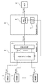
図6は、4つの3G−SDI信号を多重化して1つの12G−SDI信号として伝送する従来の映像出力表示システムを示す。図6には、複数の撮像装置1と、映像信号ルーター2と、映像信号スイッチャー3と、モニタ4と、を備えたシステムが示されている。
FIG. 6 shows a conventional video output display system that multiplexes four 3G-SDI signals and transmits them as one 12G-SDI signal. FIG. 6 shows a system including a plurality of
撮像装置1は、撮影した映像を構成する4k×2k映像信号を2SI方式を用いて4分割して得られた4つの3G−SDI信号を、4つのチャンネルを介して出力する。
The
映像信号ルーター2は、各撮像装置1から入力した4つの3G−SDI信号毎に出力チャンネルを決定するクロスポイント回路5と、クロスポイント回路5で決定された出力チャンネルを介して出力された4つの3G−SDI信号を1つの12G−SDI信号に多重化する多重化回路6と、を含む。
The
クロスポイント回路5には、複数の撮像装置1の各々からの4つのチャンネルを構成する4つのケーブル及びコネクタをそれぞれ接続するための複数の入力端子と、出力チャンネルに接続された複数の出力端子と、複数の入力端子にそれぞれ接続される複数の入力ラインと、複数の出力端子にそれぞれ接続される複数の出力ラインと、を含む。
The
クロスポイント回路5は、複数の入力ラインと複数の出力ラインとが格子状に配列されており、入力ラインと出力ラインが交差するクロスポイントの所で入力ラインと出力ラインを接続し得るように構成されている。クロスポイント回路5は、後述の映像信号スイッチャー3のユーザ入力部7からの制御信号に基づいて、所望のクロスポイントの所で入力ラインと出力ラインを接続することにより、入力端子に入力された所望の映像信号を所望の出力端子に出力することができる。
The
映像信号スイッチャー3は、ユーザ入力部7と、映像処理装置8と、を含む。ユーザ入力部7は、ユーザ入力を受け取り、当該ユーザ入力に応じた処理をクロスポイント回路5及び/又は映像処理装置8に実行させるための制御信号を送信することができる。例えば、ユーザ入力部7は、所望の撮像装置1からの映像の選択・切替えを行いモニタ4に出力するように、クロスポイント回路5の入力ラインと出力ラインを接続する制御信号をクロスポイント回路5に送信することができる。
The
映像処理装置8は、複数の撮像装置1から出力され、多重化回路6によって多重化された2SI方式の12G−SDI信号を受信し、ユーザ入力部7に対するユーザ入力に基づいて映像の加工処理を行うなどの映像処理を行うことができる。
The
モニタ4は、映像信号スイッチャー3から出力された信号に基づく映像を表示する。このように、4つの3G−SDI信号を多重化して1つの12G−SDI信号として伝送することにより、撮像装置1で撮影した映像を4k×2k映像としてモニタ4に表示することができる。
The
図6に示すような映像出力表示システムにおいては、1つの撮像装置1につき4本のケーブルを用いており、クロスポイント回路5の入力端子に接続するコネクタ数が多いことから、例えば形状が同様のケーブルやコネクタを用いて複数の撮像装置1と映像信号ルーター2との間を接続した場合など、人的ミスによるコネクタの接続間違いが起こり得る。そのため、複数の3G−SDI信号を多重化した12G−SDI信号が元の映像信号と一致しているかどうかを確認する必要がある。
In the video output display system as shown in FIG. 6, four cables are used for one
従来、モニタに表示される2SI方式の映像信号が撮像装置から出力された元の映像信号と一致しているかどうかを自動的に判定するシステムは存在しなかった。そのため、複数の信号を多重化した信号の出力が正しいかどうかは、モニタに映像を映して、画素の順番が正しいかどうかを目視で確認する方法により判断していた。 Conventionally, there has been no system that automatically determines whether or not the 2SI system video signal displayed on the monitor matches the original video signal output from the image pickup apparatus. Therefore, whether or not the output of a signal obtained by multiplexing a plurality of signals is correct is determined by a method of displaying an image on a monitor and visually confirming whether or not the order of pixels is correct.
特に、2SI方式の場合、4つに分割された信号における2つの画素を交互にマッピングして1つの映像を作成するため、目視では画素の順番が正しいかどうかを瞬時に判断するのは困難である。そのため、画素の順番が正しいかどうかの判断は、大きいモニタを使用して、画素の配置を1つ1つ細かくチェックすることによってなされていた。 In particular, in the case of the 2SI method, since two pixels in the signal divided into four are alternately mapped to create one image, it is difficult to instantly judge whether the order of the pixels is correct or not. is there. Therefore, the judgment as to whether or not the order of the pixels is correct has been made by carefully checking the arrangement of the pixels one by one using a large monitor.
しかしながら、1つの撮像装置1からの映像信号につき、このような細かいチェックをする必要であるため、時間と労力がかかっており、また大きなモニタを用意することも非常に手間がかかるものであった。また、チェック漏れなどの人的ミスがあった場合には、誤った画素配置の映像信号が伝送される事態も生じる。
However, since it is necessary to perform such a detailed check on the video signal from one
本発明は、上記課題を鑑みてなされたものであり、モニタに表示される2SI方式の映像信号が撮像装置から出力された元の映像信号と一致しているかどうかを自動的に判定する映像出力判定装置、映像出力判定方法及びそれを用いた映像信号スイッチャーを提供することを目的とする。 The present invention has been made in view of the above problems, and is a video output that automatically determines whether or not the 2SI system video signal displayed on the monitor matches the original video signal output from the image pickup apparatus. It is an object of the present invention to provide a determination device, a video output determination method, and a video signal switcher using the determination device.
上記課題を解決するために、本発明の一態様に係る映像出力判定装置は、2サンプルインターリーブ方式で伝送された1フレームでM列×Nラインの複数の画素を含む入力映像信号を受信し、前記入力映像信号における任意の1フレームからなるフレームデータを取得するフレームデータ取得部と、当該取得したフレームデータを第1乃至第4の画素グループにグループ化することによりグループ化データを生成するグループ化部と、当該生成されたグループ化データにおける前記第1乃至第4の画素グループの配置をそれぞれ入れ替えることにより複数のパターンデータを生成するパターンデータ生成部と、前記複数のパターンデータ毎に、異なる画素グループで隣り合う画素間の輝度差を計算し、前記輝度差の絶対値の和又は前記輝度差の二乗の和を計算する輝度差計算部と、前記複数のパターンデータのうち、前記輝度差の絶対値の和又は前記輝度差の二乗の和の値が最も小さいパターンデータを選択するパターンデータ選択部と、前記取得したフレームデータと当該選択されたパターンデータとが一致しているかどうかを判定して、当該判定結果を出力する判定部と、を備え、前記グループ化部は、前記フレームデータの奇数ライン上で隣り合う2つの画素を交互にグループ化することによって前記第1及び第2の画素グループを構成し、前記フレームデータの偶数ライン上で隣り合う2つの画素を交互にグループ化することによって前記第3及び第4の画素グループを構成し、前記輝度差計算部は、前記パターンデータ毎に、全画素について、M列目を除く偶数列目の各画素と、当該偶数列目の画素と同一ライン上で異なる画素グループで隣り合う各画素との輝度差を計算し、Nライン目を除く偶数ライン目の各画素と、当該偶数ライン目の画素と同一列上で異なる画素グループで隣り合う各画素との輝度差を計算することを特徴とする。 In order to solve the above problems, the video output determination device according to one aspect of the present invention receives an input video signal including a plurality of pixels of M rows × N lines in one frame transmitted by a two-sample interleaving method. A frame data acquisition unit that acquires frame data consisting of an arbitrary one frame in the input video signal, and grouping that generates grouping data by grouping the acquired frame data into first to fourth pixel groups. A pattern data generation unit that generates a plurality of pattern data by exchanging the arrangement of the unit and the first to fourth pixel groups in the generated grouping data, and a different pixel for each of the plurality of pattern data. A brightness difference calculation unit that calculates the brightness difference between adjacent pixels in a group and calculates the sum of the absolute values of the brightness difference or the sum of the squares of the brightness difference, and the brightness difference among the plurality of pattern data. It is determined whether or not the pattern data selection unit that selects the pattern data having the smallest sum of absolute values or the sum of the squares of the brightness difference and the acquired frame data and the selected pattern data match. The first and second pixels are provided with a determination unit that outputs the determination result, and the grouping unit alternately groups two adjacent pixels on an odd line of the frame data. The third and fourth pixel groups are formed by forming a group and alternately grouping two adjacent pixels on an even line of the frame data, and the brightness difference calculation unit is used for each pattern data. In addition, for all the pixels, the brightness difference between each pixel in the even column excluding the Mth column and each pixel adjacent to each other in a different pixel group on the same line as the pixel in the even column is calculated, and the Nth line is calculated. It is characterized in that the brightness difference between each pixel of the even line excluding and each pixel adjacent to each other in a different pixel group on the same row as the pixel of the even line is calculated.
本発明の一態様に係る映像信号スイッチャーは、映像出力判定装置は、本発明に係る映像出力判定装置と、前記入力映像信号と前記装置から前記判定結果とを受信する映像処理装置と、を備え、前記映像処理装置は、前記判定結果が前記取得したフレームデータと前記選択されたパターンデータとが一致していないことを示す場合には、エラー表示をするように前記入力映像信号の映像処理を行うことを特徴とする。 The video signal switcher according to one aspect of the present invention includes a video output determination device according to the present invention, and a video processing device that receives the input video signal and the determination result from the device. When the determination result indicates that the acquired frame data and the selected pattern data do not match, the video processing apparatus performs video processing of the input video signal so as to display an error. It is characterized by doing.
本発明の一態様に係る映像出力判定方法は、2サンプルインターリーブ方式で伝送された1フレームでM列×Nラインの複数の画素を含む入力映像信号を受信し、前記入力映像信号における任意の1フレームからなるフレームデータを取得するステップと、当該取得したフレームデータを第1乃至第4の画素グループにグループ化することによりグループ化データを生成するステップと、当該生成されたグループ化データにおける前記第1乃至第4の画素グループの配置をそれぞれ入れ替えることにより複数のパターンデータを生成するステップと、前記複数のパターンデータ毎に、異なる画素グループで隣り合う画素間の輝度差を計算し、前記輝度差の絶対値の和又は前記輝度差の二乗の和を計算するステップと、前記複数のパターンデータのうち、前記輝度差の絶対値の和又は前記輝度差の二乗の和の値が最も小さいパターンデータを選択するステップと、前記取得したフレームデータと当該選択されたパターンデータとが一致しているかどうかを判定して、当該判定結果を出力するステップと、を含み、前記グループ化するステップは、前記フレームデータの奇数ライン上で隣り合う2つの画素を交互にグループ化することによって前記第1及び第2の画素グループを構成するステップと、前記フレームデータの偶数ライン上で隣り合う2つの画素を交互にグループ化することによって前記第3及び第4の画素グループを構成するステップと、を含み、前記輝度差を計算するステップは、全画素について、M列目を除く偶数列目の各画素と、当該偶数列目の画素と同一ライン上で異なる画素グループで隣り合う各画素との輝度差を計算するステップと、Nライン目を除く偶数ライン目の各画素と、当該偶数ライン目の画素と同一列上で異なる画素グループで隣り合う各画素との輝度差を計算するステップと、を含むことを特徴とする。 The video output determination method according to one aspect of the present invention receives an input video signal including a plurality of pixels of M rows × N lines in one frame transmitted by a two-sample interleaving method, and any one of the input video signals. A step of acquiring frame data composed of frames, a step of generating grouping data by grouping the acquired frame data into first to fourth pixel groups, and the first step in the generated grouping data. A step of generating a plurality of pattern data by exchanging the arrangement of the first to fourth pixel groups, and a brightness difference between adjacent pixels in different pixel groups are calculated for each of the plurality of pattern data, and the brightness difference is obtained. The step of calculating the sum of the absolute values of the absolute values or the sum of the squares of the brightness differences, and the pattern data in which the sum of the absolute values of the brightness differences or the sum of the squares of the brightness differences is the smallest among the plurality of pattern data. The step of grouping includes the step of selecting the above and the step of determining whether or not the acquired frame data and the selected pattern data match and outputting the determination result. The step of forming the first and second pixel groups by alternately grouping two adjacent pixels on an odd line of frame data and alternating two adjacent pixels on an even line of frame data. Including the step of forming the third and fourth pixel groups by grouping into, and the step of calculating the brightness difference, for all the pixels, each pixel in the even column excluding the M column and each pixel in the even column, The step of calculating the brightness difference between the pixels of the even-th column and each adjacent pixel in a different pixel group on the same line, each pixel of the even-th line except the N-th line, and the same as the pixel of the even-th line. It is characterized by including a step of calculating a brightness difference between adjacent pixels in different pixel groups on a row.
本発明によると、モニタに表示される2SI方式の映像信号が撮像装置から出力された元の映像信号と一致しているかどうかを自動的に判定することが可能となるため、人的ミスを防止できるとともに、大きなモニタを用意して目視で細かくチェックをする必要がないため、画素の順番が正しいかどうかのチェックを低コストに行うことが可能となる。 According to the present invention, it is possible to automatically determine whether or not the 2SI system video signal displayed on the monitor matches the original video signal output from the image pickup apparatus, thus preventing human error. In addition, since it is not necessary to prepare a large monitor and visually check in detail, it is possible to check whether the pixel order is correct at low cost.
(実施例)
図1は、本発明の実施例に係る映像出力判定装置の構成を示す。図1には、フレームデータ取得部11と、グループ化部12と、パターンデータ生成部13と、輝度差計算部14と、判定部15と、パターンデータ選択部16と、を含む映像出力判定装置10が示されている。本発明は、モニタに表示される2SIの映像信号の画素を抽出し、その画素と隣接する画素の連続性を調べ、その並びが正しいかどうかを判断するものである。映像出力判定装置10は、後述する図5に示す映像信号スイッチャー100内に設けられている。
(Example)
FIG. 1 shows the configuration of a video output determination device according to an embodiment of the present invention. FIG. 1 shows a video output determination device including a frame
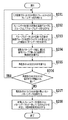
図2は、本発明の実施例に係る映像出力判定装置における処理フローを示す。図2に示されるように、ステップ201で、フレームデータ取得部11が、2SI方式で伝送された入力映像信号を受信し、当該受信した入力映像信号における任意の1フレームからなるフレームデータを取得して、グループ化部12に出力する。入力映像信号は、4k×2k信号(例えば、1フレームで3840列×2160ラインの画素を含む超高解像度信号)とすることができる。
FIG. 2 shows a processing flow in the video output determination device according to the embodiment of the present invention. As shown in FIG. 2, in step 201, the frame
ステップ202で、グループ化部12が、入力したフレームデータを第1乃至第4の画素グループG1乃至G4にグループ化することによりグループ化データを生成し、パターンデータ生成部13に出力する。図3は、ステップ202におけるデータのグループ化方法を示す。図3に示されるように、入力映像信号及びそのフレームデータは、1フレームでM列×Nラインの複数の画素を含む。ここで、フレーム内における画素の位置を、(列番号,ライン番号)で示す。
In step 202, the
ステップ202では、フレームデータの奇数ライン上で隣り合う2画素を、フレームの1列目の画素から2画素ずつ交互に第1及び第2の画素グループG1及びG2とし、フレームデータの偶数ライン上で隣り合う2画素を、フレームの1列目の画素から2画素ずつ交互に第3及び第4の画素グループG3及びG4とするようにグループ化することによってグループ化データを生成する。 In step 202, two pixels adjacent to each other on the odd-numbered line of the frame data are alternately set as the first and second pixel groups G1 and G2 by two pixels from the pixel in the first row of the frame, and are set on the even-numbered line of the frame data. Grouping data is generated by grouping two adjacent pixels into third and fourth pixel groups G3 and G4 alternately by two pixels from the first row of the frame.
例えば、図3に示されるように、奇数ラインの画素(1,1)及び(2,1)を第1の画素グループG1とし、奇数ラインの画素(3,1)及び(4,1)を第2の画素グループG2とし、以降、同一ライン上で2画素ずつ第1及び第2の画素グループG1及びG2とするように交互にグループ化する。同様に、偶数ラインの画素(1,2)及び(2,2)を第3の画素グループG3とし、偶数ラインの画素(3,2)及び(4,2)を第4の画素グループG4とし、以降、同一ライン上で2画素ずつ第3及び第4の画素グループG3及びG4とするように交互にグループ化する。 For example, as shown in FIG. 3, the odd-numbered line pixels (1,1) and (2,1) are designated as the first pixel group G1, and the odd-numbered line pixels (3,1) and (4,1) are designated. The second pixel group G2 is used, and thereafter, two pixels are alternately grouped into the first and second pixel groups G1 and G2 on the same line. Similarly, the even-numbered line pixels (1, 2) and (2, 2) are designated as the third pixel group G3, and the even-numbered line pixels (3, 2) and (4, 2) are designated as the fourth pixel group G4. After that, two pixels are alternately grouped on the same line so as to be the third and fourth pixel groups G3 and G4.
垂直方向については、例えば、奇数ラインの画素(1,3)及び(2,3)と画素(3,3)及び(4,3)とをそれぞれ第1及び第2の画素グループG1及びG2とし、偶数ラインの画素(1,4)及び(2,4)と画素(3,4)及び(4,4)とをそれぞれ第3及び第4の画素グループG3及びG4とし、以降、ライン毎に交互に第1及び第2の画素グループG1及びG2と第3及び第4の画素グループG3及びG4とするようにグループ化する。 In the vertical direction, for example, the odd-numbered line pixels (1,3) and (2,3) and the pixels (3,3) and (4,3) are designated as the first and second pixel groups G1 and G2, respectively. , Pixels (1,4) and (2,4) of even-numbered lines and pixels (3,4) and (4,4) are designated as third and fourth pixel groups G3 and G4, respectively, and thereafter, for each line. The first and second pixel groups G1 and G2 and the third and fourth pixel groups G3 and G4 are alternately grouped.
ステップ203で、パターンデータ生成部13が、入力したグループ化データにおける第1乃至第4の画素グループG1乃至G4の配置をそれぞれ入れ替えることによりその組み合わせから作成可能な複数のパターンデータを生成する。ステップ203では、第1乃至第4の画素グループG1乃至G4の配置をそれぞれ入れ替えることにより、全部で4!=4×3×2×1=24通りの2SI方式のパターンデータを生成することができる。
In step 203, the pattern
ステップ204で、輝度差計算部14が、パターンデータ毎に、異なる画素グループで隣り合う画素間の輝度差を計算する。図4を用いて、ステップ204における隣り合う画素間の輝度差の計算方法を説明する。図4(a)に示すように、ステップ204では、輝度差計算部14は、パターンデータ毎に、全画素について、M列目を除く偶数列目の各画素と、当該偶数列目の画素と同一ライン上で異なる画素グループで隣り合う各画素との輝度差を計算し、また、Nライン目を除く偶数ライン目の各画素と、当該偶数ライン目の画素と同一列上で異なる画素グループで隣り合う各画素との輝度差を計算する。
In step 204, the luminance
このように、ステップ204では、奇数ライン目の各画素と、当該奇数ライン目の画素と同一列上で異なる画素グループで隣り合う各画素との輝度差を計算するのではなく、偶数ライン目の各画素と、当該偶数ライン目の画素と同一列上で異なる画素グループで隣り合う各画素との輝度差を計算している。それにより、画素が誤って入れ替わっている場合に、より顕著に輝度差が生じさせることができる。 As described above, in step 204, instead of calculating the brightness difference between each pixel of the odd-numbered line and each pixel adjacent to the pixel of the odd-numbered line in a different pixel group on the same row, the even-numbered line is calculated. The brightness difference between each pixel and each pixel adjacent to each pixel in a different pixel group on the same row as the pixel of the even-numbered line is calculated. As a result, when the pixels are erroneously replaced, the brightness difference can be made more remarkable.
例えば、図4(b)が元の映像信号と一致するように正しく画素が配列されたパターンデータを示し、図4(c)が図4(b)に示すパターンデータから、第1の画素グループG1の輝度Bと第3の画素グループG3の輝度Bが入れ替わっているパターンデータとする。このとき、図4(c)に示すように、奇数ライン目の画素(1,1)と当該奇数ライン目の画素と同一列上で異なる画素グループで隣り合う画素(1,2)との輝度差はB5−B1であるのに対し、偶数ライン目の画素(1,2)と当該偶数ライン目の画素と同一列上で異なる画素グループで隣り合う画素(1,3)との輝度差はB1−B13であるため、より顕著に輝度差が生じることが理解される。 For example, FIG. 4B shows pattern data in which pixels are correctly arranged so as to match the original video signal, and FIG. 4C shows a first pixel group from the pattern data shown in FIG. 4B. Let the pattern data be such that the brightness B of G1 and the brightness B of the third pixel group G3 are interchanged. At this time, as shown in FIG. 4C, the brightness of the pixels of the odd-numbered lines (1,1) and the pixels (1,2) adjacent to each other in different pixel groups on the same row as the pixels of the odd-numbered lines. While the difference is B5-B1, the difference in brightness between the pixels of the even-numbered lines (1, 2) and the pixels (1, 3) adjacent to each other in different pixel groups on the same row as the pixels of the even-numbered lines is Since it is B1-B13, it is understood that a difference in brightness occurs more remarkably.
ステップ205で、輝度差計算部14が、パターンデータ毎に、ステップ204で計算した各輝度差の絶対値の和(SAD:Sum of Absolute Differences)又は各輝度差の2乗の和(SSD:Sum of Squared Differences)を計算する。
In
ステップ206で、判定部15が、例えば画面が真っ白の場合など、計算したSAD又はSSDの値が所定の閾値よりも低いかどうかを判定する。計算したSAD又はSSDの値が所定の閾値よりも低い場合、ステップ201に戻って、フレームデータを新しく取得し直す。計算したSAD又はSSDの値が所定の閾値以上である場合、以下のステップ208に進む。ここで、ステップ206を省略して、ステップ205から以下のステップ207に移行するように構成してもよい。
In
ステップ207で、パターンデータ選択部16が、全てのパターンデータのうち、SAD又はSSDの値が最も小さいパターンデータを選択する。当該選択したパターンデータは、画素グループの各画素が元の映像信号と一致するように正しく配列されたパターンデータとされる。
In
ステップ208で、判定部15が、ステップ201で取得したフレームデータとステップ208で選択されたパターンデータとが一致しているかどうかを判定し、当該判定結果を出力する。
In
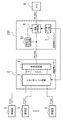
図5は、本発明の実施例に係る映像出力判定装置を用いた映像出力表示システムを示す。図5には、図6で示した映像出力表示システムの映像信号スイッチャー3に、本発明に係る映像出力判定装置10がさらに設けられて構成された映像信号スイッチャー100を備えた映像出力表示システムが示されている。
FIG. 5 shows a video output display system using the video output determination device according to the embodiment of the present invention. FIG. 5 shows a video output display system including a
図5に示す映像出力表示システムでは、映像処理装置8には、多重化回路6からの入力映像信号を受信すると共に、ステップ201で取得したフレームデータとステップ208で選択されたパターンデータとが一致してるかどうかの判定結果が映像出力判定装置10から受信される。ステップ201で取得したフレームデータとステップ208で選択されたパターンデータとが一致しないと判定された場合には、映像処理装置8は、当該判定結果に基づいて、モニタ4においてエラー表示をするように入力映像信号の映像処理を行うことができる。
In the video output display system shown in FIG. 5, the
このように、本発明に係る映像出力判定装置を用いた映像出力表示システムによると、映像信号スイッチャー100内に本発明に係る映像出力判定装置10を設けることにより、映像信号スイッチャー100のユーザ入力部7によって所望の映像に切替えられた場合に、その映像信号と元の映像信号とが一致しているかどうかを瞬時に判断することができ、一致していない場合にはエラー表示を行うことが可能となる。
As described above, according to the video output display system using the video output determination device according to the present invention, the user input unit of the
Claims (4)
当該取得したフレームデータを第1乃至第4の画素グループにグループ化することによりグループ化データを生成するグループ化部と、
当該生成されたグループ化データにおける前記第1乃至第4の画素グループの配置をそれぞれ入れ替えることにより複数のパターンデータを生成するパターンデータ生成部と、
前記複数のパターンデータ毎に、異なる画素グループで隣り合う画素間の輝度差を計算し、前記輝度差の絶対値の和又は前記輝度差の二乗の和を計算する輝度差計算部と、
前記複数のパターンデータのうち、前記輝度差の絶対値の和又は前記輝度差の二乗の和の値が最も小さいパターンデータを選択するパターンデータ選択部と、
前記取得したフレームデータと当該選択されたパターンデータとが一致しているかどうかを判定して、当該判定結果を出力する判定部と、
を備え、
前記グループ化部は、
前記フレームデータの奇数ライン上で隣り合う2つの画素を交互にグループ化することによって前記第1及び第2の画素グループを構成し、
前記フレームデータの偶数ライン上で隣り合う2つの画素を交互にグループ化することによって前記第3及び第4の画素グループを構成し、
前記輝度差計算部は、前記パターンデータ毎に、全画素について、
M列目を除く偶数列目の各画素と、当該偶数列目の画素と同一ライン上で異なる画素グループで隣り合う各画素との輝度差を計算し、Nライン目を除く偶数ライン目の各画素と、当該偶数ライン目の画素と同一列上で異なる画素グループで隣り合う各画素との輝度差を計算することを特徴とする装置。 A frame data acquisition unit that receives an input video signal including a plurality of pixels of M columns × N lines in one frame transmitted by a two-sample interleaving method and acquires frame data consisting of an arbitrary one frame in the input video signal. ,
A grouping unit that generates grouping data by grouping the acquired frame data into first to fourth pixel groups, and a grouping unit.
A pattern data generation unit that generates a plurality of pattern data by exchanging the arrangement of the first to fourth pixel groups in the generated grouping data, and
A luminance difference calculation unit that calculates the luminance difference between adjacent pixels in different pixel groups for each of the plurality of pattern data, and calculates the sum of the absolute values of the luminance differences or the sum of the squares of the luminance differences.
A pattern data selection unit that selects the pattern data having the smallest sum of the absolute values of the luminance differences or the sum of the squares of the luminance differences among the plurality of pattern data.
A determination unit that determines whether or not the acquired frame data and the selected pattern data match, and outputs the determination result.
With
The grouping unit
The first and second pixel groups are formed by alternately grouping two adjacent pixels on an odd line of the frame data.
The third and fourth pixel groups are formed by alternately grouping two adjacent pixels on an even line of the frame data.
The luminance difference calculation unit uses the pattern data for all pixels.
Calculate the brightness difference between each pixel in the even-numbered column excluding the M-th column and each pixel adjacent to each pixel in a different pixel group on the same line as the pixel in the even-numbered column, and each of the even-numbered lines excluding the Nth line. A device characterized by calculating the brightness difference between a pixel and each adjacent pixel in a different pixel group on the same row as the pixel of the even-numbered line.
前記輝度差の絶対値の和又は前記輝度差の二乗の和の値が所定の閾値以上であると判定された場合に、前記パターンデータ選択部が、前記輝度差の絶対値の和又は前記輝度差の二乗の和の値が最も小さいパターンデータを選択することを特徴とする請求項1に記載の装置。 The determination unit further determines whether the sum of the absolute values of the luminance differences or the sum of the squares of the luminance differences is lower than a predetermined threshold value.
When it is determined that the sum of the absolute values of the luminance differences or the sum of the squares of the luminance differences is equal to or greater than a predetermined threshold value, the pattern data selection unit determines the sum of the absolute values of the luminance differences or the luminance. The apparatus according to claim 1, wherein the pattern data having the smallest sum of the squares of the differences is selected.
前記入力映像信号と前記装置から前記判定結果とを受信する映像処理装置と、を備え、
前記映像処理装置は、前記判定結果が前記取得したフレームデータと前記選択されたパターンデータとが一致していないことを示す場合には、エラー表示をするように前記入力映像信号の映像処理を行うことを特徴とする映像信号スイッチャー。 The device according to claim 1 or 2,
A video processing device that receives the input video signal and the determination result from the device is provided.
When the determination result indicates that the acquired frame data and the selected pattern data do not match, the video processing apparatus performs video processing of the input video signal so as to display an error. A video signal switcher that features this.
当該取得したフレームデータを第1乃至第4の画素グループにグループ化することによりグループ化データを生成するステップと、
当該生成されたグループ化データにおける前記第1乃至第4の画素グループの配置をそれぞれ入れ替えることにより複数のパターンデータを生成するステップと、
前記複数のパターンデータ毎に、異なる画素グループで隣り合う画素間の輝度差を計算し、前記輝度差の絶対値の和又は前記輝度差の二乗の和を計算するステップと、
前記複数のパターンデータのうち、前記輝度差の絶対値の和又は前記輝度差の二乗の和の値が最も小さいパターンデータを選択するステップと、
前記取得したフレームデータと当該選択されたパターンデータとが一致しているかどうかを判定して、当該判定結果を出力するステップと、
を含み、
前記グループ化するステップは、
前記フレームデータの奇数ライン上で隣り合う2つの画素を交互にグループ化することによって前記第1及び第2の画素グループを構成するステップと、
前記フレームデータの偶数ライン上で隣り合う2つの画素を交互にグループ化することによって前記第3及び第4の画素グループを構成するステップと、
を含み、
前記輝度差を計算するステップは、全画素について、
M列目を除く偶数列目の各画素と、当該偶数列目の画素と同一ライン上で異なる画素グループで隣り合う各画素との輝度差を計算するステップと、
Nライン目を除く偶数ライン目の各画素と、当該偶数ライン目の画素と同一列上で異なる画素グループで隣り合う各画素との輝度差を計算するステップと、
を含むことを特徴とする方法。 A step of receiving an input video signal including a plurality of pixels of M columns × N lines in one frame transmitted by a two-sample interleaving method and acquiring frame data consisting of an arbitrary one frame in the input video signal.
A step of generating grouping data by grouping the acquired frame data into first to fourth pixel groups, and
A step of generating a plurality of pattern data by exchanging the arrangement of the first to fourth pixel groups in the generated grouping data, and
A step of calculating the luminance difference between adjacent pixels in different pixel groups for each of the plurality of pattern data, and calculating the sum of the absolute values of the luminance differences or the sum of the squares of the luminance differences.
A step of selecting the pattern data having the smallest sum of the absolute values of the luminance differences or the sum of the squares of the luminance differences among the plurality of pattern data.
A step of determining whether or not the acquired frame data and the selected pattern data match, and outputting the determination result.
Including
The grouping steps
A step of forming the first and second pixel groups by alternately grouping two adjacent pixels on an odd line of the frame data.
A step of forming the third and fourth pixel groups by alternately grouping two adjacent pixels on an even line of the frame data, and
Including
The step of calculating the luminance difference is for all pixels.
A step of calculating the brightness difference between each pixel in the even-numbered column excluding the M-th column and each pixel adjacent to each pixel in a different pixel group on the same line as the pixel in the even-numbered column.
A step of calculating the brightness difference between each pixel of the even-numbered line excluding the N-th line and each pixel adjacent to each pixel in a different pixel group on the same row as the pixel of the even-numbered line.
A method characterized by including.
Priority Applications (1)
| Application Number | Priority Date | Filing Date | Title |
|---|---|---|---|
| JP2017094834A JP6777587B2 (en) | 2017-05-11 | 2017-05-11 | Video output judgment device, video output judgment method and video signal switcher using it |
Applications Claiming Priority (1)
| Application Number | Priority Date | Filing Date | Title |
|---|---|---|---|
| JP2017094834A JP6777587B2 (en) | 2017-05-11 | 2017-05-11 | Video output judgment device, video output judgment method and video signal switcher using it |
Publications (2)
| Publication Number | Publication Date |
|---|---|
| JP2018191249A JP2018191249A (en) | 2018-11-29 |
| JP6777587B2 true JP6777587B2 (en) | 2020-10-28 |
Family
ID=64479197
Family Applications (1)
| Application Number | Title | Priority Date | Filing Date |
|---|---|---|---|
| JP2017094834A Active JP6777587B2 (en) | 2017-05-11 | 2017-05-11 | Video output judgment device, video output judgment method and video signal switcher using it |
Country Status (1)
| Country | Link |
|---|---|
| JP (1) | JP6777587B2 (en) |
Family Cites Families (5)
| Publication number | Priority date | Publication date | Assignee | Title |
|---|---|---|---|---|
| JP2000032477A (en) * | 1998-07-09 | 2000-01-28 | Matsushita Electric Ind Co Ltd | Video signal processing apparatus and video signal processing method |
| GB2422975B (en) * | 2005-02-08 | 2007-12-12 | Imagination Tech Ltd | Conversion of video data from interlaced to non-interlaced format |
| JP4557016B2 (en) * | 2007-11-22 | 2010-10-06 | ソニー株式会社 | Signal transmitter |
| JP4645638B2 (en) * | 2007-11-22 | 2011-03-09 | ソニー株式会社 | Signal transmitting apparatus, signal transmitting method, signal receiving apparatus, and signal receiving method |
| WO2016151999A1 (en) * | 2015-03-24 | 2016-09-29 | ソニー株式会社 | Image transmission device and link status confirmation method |
-
2017
- 2017-05-11 JP JP2017094834A patent/JP6777587B2/en active Active
Also Published As
| Publication number | Publication date |
|---|---|
| JP2018191249A (en) | 2018-11-29 |
Similar Documents
| Publication | Publication Date | Title |
|---|---|---|
| JP4645638B2 (en) | Signal transmitting apparatus, signal transmitting method, signal receiving apparatus, and signal receiving method | |
| US7262746B2 (en) | Video wall | |
| CN104284205B (en) | Signal handling equipment, signal processing method, program and signal transmission system | |
| WO2018056002A1 (en) | Video monitoring system | |
| KR20150083012A (en) | Method and Apparatus for Generating Single Bit Stream from Multiple Video Stream | |
| CN100502520C (en) | Apparatus and method for generating 3D image signal using space-division method | |
| JP6362116B2 (en) | Display device, control method therefor, program, and storage medium | |
| JP6729573B2 (en) | Signal processing device, signal processing method, program, and signal transmission system | |
| US10250920B2 (en) | Image transmission apparatus and link status confirmation method | |
| US8780171B2 (en) | Video signal processor and video signal processing method with markers for indicating correct component connection | |
| JP6777587B2 (en) | Video output judgment device, video output judgment method and video signal switcher using it | |
| WO2004066203A2 (en) | A general purpose stereoscopic 3d format conversion system and method | |
| JP5985118B1 (en) | Display control apparatus and endoscope system | |
| JP5288485B2 (en) | Video signal transmission device | |
| KR101637193B1 (en) | The layer is set as distributed processing type multi channel image composite system and the control method | |
| KR20050095082A (en) | Image composition apparatus of stereo camera | |
| JP5635673B2 (en) | Image encoding device | |
| JP5401164B2 (en) | Receiver | |
| KR100494177B1 (en) | apparatus and method for multi-channel video distribution | |
| CN106888373A (en) | The processing unit and processing system of a kind of 3-D view | |
| TR201706829A3 (en) | A VIDEO WALL SYSTEM DATA TRANSFER METHOD | |
| JP6576974B2 (en) | Image composition system for monitor and image composition method for monitor | |
| JP2016103686A (en) | Imaging device | |
| JP2015231088A (en) | Reference color signal pattern and reference color signal generator | |
| JP2013031143A (en) | Image processing device and image processing method |
Legal Events
| Date | Code | Title | Description |
|---|---|---|---|
| A621 | Written request for application examination |
Free format text: JAPANESE INTERMEDIATE CODE: A621 Effective date: 20200422 |
|
| A977 | Report on retrieval |
Free format text: JAPANESE INTERMEDIATE CODE: A971007 Effective date: 20200923 |
|
| TRDD | Decision of grant or rejection written | ||
| A01 | Written decision to grant a patent or to grant a registration (utility model) |
Free format text: JAPANESE INTERMEDIATE CODE: A01 Effective date: 20200929 |
|
| A61 | First payment of annual fees (during grant procedure) |
Free format text: JAPANESE INTERMEDIATE CODE: A61 Effective date: 20201008 |
|
| R150 | Certificate of patent or registration of utility model |
Ref document number: 6777587 Country of ref document: JP Free format text: JAPANESE INTERMEDIATE CODE: R150 |
|
| R250 | Receipt of annual fees |
Free format text: JAPANESE INTERMEDIATE CODE: R250 |
|
| R250 | Receipt of annual fees |
Free format text: JAPANESE INTERMEDIATE CODE: R250 |
|
| R250 | Receipt of annual fees |
Free format text: JAPANESE INTERMEDIATE CODE: R250 |