JP6776402B2 - Systems and methods for fixing tissue to bone - Google Patents
Systems and methods for fixing tissue to bone Download PDFInfo
- Publication number
- JP6776402B2 JP6776402B2 JP2019088324A JP2019088324A JP6776402B2 JP 6776402 B2 JP6776402 B2 JP 6776402B2 JP 2019088324 A JP2019088324 A JP 2019088324A JP 2019088324 A JP2019088324 A JP 2019088324A JP 6776402 B2 JP6776402 B2 JP 6776402B2
- Authority
- JP
- Japan
- Prior art keywords
- anchor
- spreader
- distal
- anchor body
- bone
- Prior art date
- Legal status (The legal status is an assumption and is not a legal conclusion. Google has not performed a legal analysis and makes no representation as to the accuracy of the status listed.)
- Active
Links
Images


Classifications
-
- A—HUMAN NECESSITIES
- A61—MEDICAL OR VETERINARY SCIENCE; HYGIENE
- A61F—FILTERS IMPLANTABLE INTO BLOOD VESSELS; PROSTHESES; DEVICES PROVIDING PATENCY TO, OR PREVENTING COLLAPSING OF, TUBULAR STRUCTURES OF THE BODY, e.g. STENTS; ORTHOPAEDIC, NURSING OR CONTRACEPTIVE DEVICES; FOMENTATION; TREATMENT OR PROTECTION OF EYES OR EARS; BANDAGES, DRESSINGS OR ABSORBENT PADS; FIRST-AID KITS
- A61F2/00—Filters implantable into blood vessels; Prostheses, i.e. artificial substitutes or replacements for parts of the body; Appliances for connecting them with the body; Devices providing patency to, or preventing collapsing of, tubular structures of the body, e.g. stents
- A61F2/02—Prostheses implantable into the body
- A61F2/08—Muscles; Tendons; Ligaments
- A61F2/0811—Fixation devices for tendons or ligaments
-
- A—HUMAN NECESSITIES
- A61—MEDICAL OR VETERINARY SCIENCE; HYGIENE
- A61B—DIAGNOSIS; SURGERY; IDENTIFICATION
- A61B17/00—Surgical instruments, devices or methods, e.g. tourniquets
- A61B17/04—Surgical instruments, devices or methods, e.g. tourniquets for suturing wounds; Holders or packages for needles or suture materials
- A61B17/0401—Suture anchors, buttons or pledgets, i.e. means for attaching sutures to bone, cartilage or soft tissue; Instruments for applying or removing suture anchors
- A61B2017/0403—Dowels
-
- A—HUMAN NECESSITIES
- A61—MEDICAL OR VETERINARY SCIENCE; HYGIENE
- A61B—DIAGNOSIS; SURGERY; IDENTIFICATION
- A61B17/00—Surgical instruments, devices or methods, e.g. tourniquets
- A61B17/04—Surgical instruments, devices or methods, e.g. tourniquets for suturing wounds; Holders or packages for needles or suture materials
- A61B17/0401—Suture anchors, buttons or pledgets, i.e. means for attaching sutures to bone, cartilage or soft tissue; Instruments for applying or removing suture anchors
- A61B2017/0409—Instruments for applying suture anchors
-
- A—HUMAN NECESSITIES
- A61—MEDICAL OR VETERINARY SCIENCE; HYGIENE
- A61B—DIAGNOSIS; SURGERY; IDENTIFICATION
- A61B17/00—Surgical instruments, devices or methods, e.g. tourniquets
- A61B17/04—Surgical instruments, devices or methods, e.g. tourniquets for suturing wounds; Holders or packages for needles or suture materials
- A61B17/0401—Suture anchors, buttons or pledgets, i.e. means for attaching sutures to bone, cartilage or soft tissue; Instruments for applying or removing suture anchors
- A61B2017/0427—Suture anchors, buttons or pledgets, i.e. means for attaching sutures to bone, cartilage or soft tissue; Instruments for applying or removing suture anchors having anchoring barbs or pins extending outwardly from the anchor body
- A61B2017/0429—Suture anchors, buttons or pledgets, i.e. means for attaching sutures to bone, cartilage or soft tissue; Instruments for applying or removing suture anchors having anchoring barbs or pins extending outwardly from the anchor body the barbs being expanded by a mechanical mechanism which also locks them in the expanded state
- A61B2017/043—Suture anchors, buttons or pledgets, i.e. means for attaching sutures to bone, cartilage or soft tissue; Instruments for applying or removing suture anchors having anchoring barbs or pins extending outwardly from the anchor body the barbs being expanded by a mechanical mechanism which also locks them in the expanded state by insertion of a separate spreading member into the anchor
- A61B2017/0432—Suture anchors, buttons or pledgets, i.e. means for attaching sutures to bone, cartilage or soft tissue; Instruments for applying or removing suture anchors having anchoring barbs or pins extending outwardly from the anchor body the barbs being expanded by a mechanical mechanism which also locks them in the expanded state by insertion of a separate spreading member into the anchor the separate member staying in the anchor after placement
-
- A—HUMAN NECESSITIES
- A61—MEDICAL OR VETERINARY SCIENCE; HYGIENE
- A61F—FILTERS IMPLANTABLE INTO BLOOD VESSELS; PROSTHESES; DEVICES PROVIDING PATENCY TO, OR PREVENTING COLLAPSING OF, TUBULAR STRUCTURES OF THE BODY, e.g. STENTS; ORTHOPAEDIC, NURSING OR CONTRACEPTIVE DEVICES; FOMENTATION; TREATMENT OR PROTECTION OF EYES OR EARS; BANDAGES, DRESSINGS OR ABSORBENT PADS; FIRST-AID KITS
- A61F2/00—Filters implantable into blood vessels; Prostheses, i.e. artificial substitutes or replacements for parts of the body; Appliances for connecting them with the body; Devices providing patency to, or preventing collapsing of, tubular structures of the body, e.g. stents
- A61F2/02—Prostheses implantable into the body
- A61F2/08—Muscles; Tendons; Ligaments
- A61F2/0811—Fixation devices for tendons or ligaments
- A61F2002/0817—Structure of the anchor
- A61F2002/0823—Modular anchors comprising a plurality of separate parts
- A61F2002/0835—Modular anchors comprising a plurality of separate parts with deformation of anchor parts, e.g. expansion of dowel by set screw
-
- A—HUMAN NECESSITIES
- A61—MEDICAL OR VETERINARY SCIENCE; HYGIENE
- A61F—FILTERS IMPLANTABLE INTO BLOOD VESSELS; PROSTHESES; DEVICES PROVIDING PATENCY TO, OR PREVENTING COLLAPSING OF, TUBULAR STRUCTURES OF THE BODY, e.g. STENTS; ORTHOPAEDIC, NURSING OR CONTRACEPTIVE DEVICES; FOMENTATION; TREATMENT OR PROTECTION OF EYES OR EARS; BANDAGES, DRESSINGS OR ABSORBENT PADS; FIRST-AID KITS
- A61F2/00—Filters implantable into blood vessels; Prostheses, i.e. artificial substitutes or replacements for parts of the body; Appliances for connecting them with the body; Devices providing patency to, or preventing collapsing of, tubular structures of the body, e.g. stents
- A61F2/02—Prostheses implantable into the body
- A61F2/08—Muscles; Tendons; Ligaments
- A61F2/0811—Fixation devices for tendons or ligaments
- A61F2002/0847—Mode of fixation of anchor to tendon or ligament
- A61F2002/0852—Fixation of a loop or U-turn, e.g. eyelets, anchor having multiple holes
-
- A—HUMAN NECESSITIES
- A61—MEDICAL OR VETERINARY SCIENCE; HYGIENE
- A61F—FILTERS IMPLANTABLE INTO BLOOD VESSELS; PROSTHESES; DEVICES PROVIDING PATENCY TO, OR PREVENTING COLLAPSING OF, TUBULAR STRUCTURES OF THE BODY, e.g. STENTS; ORTHOPAEDIC, NURSING OR CONTRACEPTIVE DEVICES; FOMENTATION; TREATMENT OR PROTECTION OF EYES OR EARS; BANDAGES, DRESSINGS OR ABSORBENT PADS; FIRST-AID KITS
- A61F2/00—Filters implantable into blood vessels; Prostheses, i.e. artificial substitutes or replacements for parts of the body; Appliances for connecting them with the body; Devices providing patency to, or preventing collapsing of, tubular structures of the body, e.g. stents
- A61F2/02—Prostheses implantable into the body
- A61F2/08—Muscles; Tendons; Ligaments
- A61F2/0811—Fixation devices for tendons or ligaments
- A61F2002/0847—Mode of fixation of anchor to tendon or ligament
- A61F2002/0858—Fixation of tendon or ligament between anchor and bone, e.g. interference screws, wedges
-
- A—HUMAN NECESSITIES
- A61—MEDICAL OR VETERINARY SCIENCE; HYGIENE
- A61F—FILTERS IMPLANTABLE INTO BLOOD VESSELS; PROSTHESES; DEVICES PROVIDING PATENCY TO, OR PREVENTING COLLAPSING OF, TUBULAR STRUCTURES OF THE BODY, e.g. STENTS; ORTHOPAEDIC, NURSING OR CONTRACEPTIVE DEVICES; FOMENTATION; TREATMENT OR PROTECTION OF EYES OR EARS; BANDAGES, DRESSINGS OR ABSORBENT PADS; FIRST-AID KITS
- A61F2/00—Filters implantable into blood vessels; Prostheses, i.e. artificial substitutes or replacements for parts of the body; Appliances for connecting them with the body; Devices providing patency to, or preventing collapsing of, tubular structures of the body, e.g. stents
- A61F2/02—Prostheses implantable into the body
- A61F2/08—Muscles; Tendons; Ligaments
- A61F2/0811—Fixation devices for tendons or ligaments
- A61F2002/0876—Position of anchor in respect to the bone
- A61F2002/0882—Anchor in or on top of a bone tunnel, i.e. a hole running through the entire bone
Description
(参照による優先権出願の組込み)
本願は、参照によりその全体を本明細書に組み込む、2013年3月15日出願の米国仮出願第61/801255号の利益および優先権を主張するものである。
(Incorporation of priority application by reference)
The present application claims the interests and priority of US Provisional Application No. 61/801255 filed March 15, 2013, which is incorporated herein by reference in its entirety.
本発明は、医療デバイスおよび医療手順に関する。さらに詳細には、本発明は、軟組織を骨などの剛性材料に固定するデバイスおよび方法に関する。本明細書には、整形外科手順において腱または靱帯などの組織を骨に固定するシステムおよび方法を開示する。 The present invention relates to medical devices and medical procedures. More specifically, the present invention relates to devices and methods for fixing soft tissue to rigid materials such as bone. This specification discloses a system and method for fixing a tissue such as a tendon or a ligament to a bone in an orthopedic procedure.
外科医が腱または靱帯などの軟結合組織を骨に取り付ける必要がある医療手順はいくつかある。1つの一般的な例は、断裂したACLの治療のために通常行われる外科的手順である、前十字靱帯(「ACL」)再建である。ACLは、膝にある4つの主要な靱帯のうちの1つである。ACL再建は、独立した手順として行うこともできるが、多重修復手術の一部として半月板損傷および軟骨損傷の治療とともに行われることが多い。 There are several medical procedures that require a surgeon to attach soft connective tissue, such as tendons or ligaments, to bone. One common example is anterior cruciate ligament (“ACL”) reconstruction, which is a surgical procedure commonly performed for the treatment of ruptured ACLs. ACL is one of the four major ligaments in the knee. ACL reconstruction can be performed as an independent procedure, but is often performed with the treatment of meniscal and cartilage injuries as part of multiple repair surgery.
ACL再建は、損傷したACLを、一般に患者の膝蓋腱または腿筋腱あるいは死体の靱帯から形成される組織移植片で置換する手順である。ACL再建を行うためには、組織移植片を採取してサイジングするステップと、組織移植片をピンの端部に固定するステップと、現在の損傷したACLを除去するステップと、脛骨を貫通する内腔および大腿骨中のめくら穴を形成する骨孔を穿孔するステップと、ピンおよび組織移植片をこの内腔に通してめくら穴の中まで入れるステップと、第1のアンカを大腿骨のめくら穴の中にねじ込み、第2のアンカを脛骨の中にねじ込んで、組織移植片を骨に押し付けた状態で捕捉し、しっかりと骨に固定するステップという、複数のステップを通常は必要とする、外科的手順が使用される。独立した手順としても、ACL再建は、関節鏡検査的に行うことは困難である。 ACL reconstruction is a procedure in which an injured ACL is replaced with a tissue graft generally formed from the patient's patellar or femoral tendon or the ligament of the corpse. To perform ACL reconstruction, a step of collecting and sizing the tissue graft, a step of fixing the tissue graft to the end of the pin, a step of removing the current damaged ACL, and a step of penetrating the tibia. The step of drilling the bone hole that forms the blind hole in the cavity and the tibia, the step of inserting the pin and tissue graft through this cavity into the blind hole, and the first anchor in the tibial blind hole. Surgery, which usually requires multiple steps: screwing into the bone, screwing the second anchor into the tibia, capturing the tissue graft while pressing it against the bone, and firmly fixing it to the bone. Procedure is used. Even as an independent procedure, ACL reconstruction is difficult to perform arthroscopically.
最近実用化されたシステムでも、依然として複数のステップおよび器具が必要となる。 Even recently put into practical use systems still require multiple steps and instruments.
本明細書に開示するのは、前述の必要に対処することができる前十字靱帯(ACL)修復を実行するための骨アンカおよび方法の様々な実施形態である。本発明のいくつかの実施形態では、前十字靱帯(ACL)修復方法であって、脛骨に骨孔を形成するステップであり、骨孔が、脛骨の一方の側の近位開口、および脛骨の反対側の遠位開口を備えるステップと、骨孔に軟組織を通すステップと、軟組織を大腿骨に固定するステップと、骨孔の近位開口に、アンカの遠位端部が骨孔の遠位開口に隣接する位置までアンカを挿入するステップであり、アンカが、内部空洞を有する拡張可能アンカ本体、およびスプレッダを備えるステップと、エキスパンダを内部空洞中に滑動させることにより、アンカ本体の少なくとも一部分を外側に拡張させるステップであり、拡張が完了したときに、骨孔の遠位開口に隣接するアンカ本体の少なくとも一部分が拡張するステップと、を含む方法が提供される。 Disclosed herein are various embodiments of bone anchors and methods for performing anterior cruciate ligament (ACL) repair that can address the aforementioned needs. In some embodiments of the invention, an anterior cruciate ligament (ACL) repair method, the step of forming a bone hole in the tibia, where the bone hole is the proximal opening on one side of the tibia, and the tibia. A step with a contralateral distal opening, a step of passing soft tissue through the bone hole, a step of fixing the soft tissue to the tibia, and a proximal opening of the bone hole, with the distal end of the anchor being distal to the bone hole. A step of inserting the anchor to a position adjacent to the opening, where the anchor comprises an expandable anchor body with an internal cavity and a spreader, and at least a portion of the anchor body by sliding the expander into the internal cavity. Is provided, the step comprising expanding at least a portion of the anchor body adjacent to the distal opening of the bone hole when the expansion is complete.
本発明のいくつかの実施形態では、アンカが挿入されたとき、アンカは、骨孔の実質的に全長にわたって延びる。いくつかの実施形態では、アンカが拡張したときに、アンカの少なくとも一部分は、外側に拡張しない。さらに別の実施形態では、外側に拡張しない部分は、アンカ先端を備える。 In some embodiments of the invention, when the anchor is inserted, the anchor extends substantially over the entire length of the bone hole. In some embodiments, when the anchor expands, at least a portion of the anchor does not extend outward. In yet another embodiment, the portion that does not extend outward is provided with an anchor tip.
本発明のいくつかの実施形態では、ACL修復方法であって、脛骨に骨孔を形成するステップであり、骨孔が、脛骨の一方の側の近位開口、および脛骨の反対側の遠位開口を備えるステップと、骨孔に軟組織を通すステップと、軟組織を大腿骨に固定するステップと、骨孔の近位開口に、アンカの遠位端部が骨孔の遠位開口に隣接する位置までアンカを挿入するステップであり、アンカが、約30mmを超える長さであり、内部空洞を有する拡張可能アンカ本体、およびスプレッダを備えるステップと、エキスパンダを内部空洞中に滑動させることにより、アンカ本体の少なくとも一部分を外側に拡張させるステップであり、拡張が完了したときに、骨孔の遠位開口に隣接するアンカ本体の少なくとも一部分が拡張するステップと、を含む方法が提供される。 In some embodiments of the invention, it is an ACL repair method, the step of forming a bone hole in the tibia, where the bone hole is a proximal opening on one side of the tibia and distal on the opposite side of the tibia. A step with an opening, a step of passing soft tissue through the bone hole, a step of fixing the soft tissue to the tibia, and a position where the distal end of the anchor is adjacent to the distal opening of the bone hole at the proximal opening of the bone hole. By sliding the expander into the internal cavity, with the step of inserting the anchor up to, the anchor having an expandable anchor body over about 30 mm and having an internal cavity, and a spreader. A method is provided that includes a step of expanding at least a portion of the body outwards, a step of expanding at least a portion of the anchor body adjacent to the distal opening of the bone hole when the expansion is complete.
本発明のいくつかの実施形態では、ACL修復方法であって、脛骨に骨孔を形成するステップであり、骨孔が、脛骨の一方の側の近位開口、および脛骨の反対側の遠位開口を備えるステップと、骨孔に軟組織を通すステップと、軟組織を大腿骨に固定するステップと、骨孔の近位開口に、アンカの遠位端部が骨孔の遠位開口に隣接する位置までアンカを挿入するステップであり、アンカが、約35mmを超える長さであり、内部空洞を有する拡張可能アンカ本体、およびスプレッダを備えるステップと、エキスパンダを内部空洞中に滑動させることにより、アンカ本体の少なくとも一部分を外側に拡張させるステップであり、拡張が完了したときに、骨孔の遠位開口に隣接するアンカ本体の少なくとも一部分が拡張するステップと、を含む方法が提供される。 In some embodiments of the invention, it is an ACL repair method, the step of forming a bone hole in the tibia, where the bone hole is a proximal opening on one side of the tibia and distal on the opposite side of the tibia. A step with an opening, a step of passing soft tissue through the bone hole, a step of fixing the soft tissue to the tibia, and a position where the distal end of the anchor is adjacent to the distal opening of the bone hole at the proximal opening of the bone hole. By sliding the expander into the internal cavity, with the step of inserting the anchor up to, the anchor having a length of more than about 35 mm and having an expandable anchor body with an internal cavity, and a spreader. A method is provided that includes a step of expanding at least a portion of the body outwards, a step of expanding at least a portion of the anchor body adjacent to the distal opening of the bone hole when the expansion is complete.
本発明のいくつかの実施形態では、ACL修復方法であって、脛骨に骨孔を形成するステップであり、骨孔が、脛骨の一方の側の近位開口、および脛骨の反対側の遠位開口を備えるステップと、骨孔に軟組織を通すステップと、軟組織を大腿骨に固定するステップと、骨孔の近位開口に、アンカの遠位端部が骨孔の遠位開口に隣接する位置までアンカを挿入するステップであり、アンカが、約40mmを超える長さであり、内部空洞を有する拡張可能アンカ本体、およびスプレッダを備えるステップと、エキスパンダを内部空洞中に滑動させることにより、アンカ本体の少なくとも一部分を外側に拡張させるステップであり、拡張が完了したときに、骨孔の遠位開口に隣接するアンカ本体の少なくとも一部分が拡張するステップと、を含む方法が提供される。 In some embodiments of the invention, it is an ACL repair method, the step of forming a bone hole in the tibia, where the bone hole is a proximal opening on one side of the tibia and distal on the opposite side of the tibia. A step with an opening, a step of passing soft tissue through the bone hole, a step of fixing the soft tissue to the tibia, and a position where the distal end of the anchor is adjacent to the distal opening of the bone hole at the proximal opening of the bone hole. By sliding the expander into the internal cavity, with the step of inserting the anchor up to, the anchor having an expandable anchor body over about 40 mm and having an internal cavity, and a spreader. A method is provided that includes a step of expanding at least a portion of the body outwards, a step of expanding at least a portion of the anchor body adjacent to the distal opening of the bone hole when the expansion is complete.
本発明の他の実施形態では、前十字靱帯(ACL)修復方法であって、脛骨に骨孔を形成するステップであり、骨孔が、脛骨の一方の側の近位開口、および脛骨の反対側の遠位開口を備えるステップと、骨孔に軟組織を通すステップと、軟組織を大腿骨に固定するステップと、骨孔の近位開口に、アンカの遠位端部が骨孔の遠位開口に隣接する位置までアンカを挿入するステップであり、アンカが、内部空洞を有する拡張可能アンカ本体、およびスプレッダを備えるステップと、エキスパンダを内部空洞中に挿入することにより、アンカ本体の少なくとも一部分を外側に拡張させるステップであり、拡張が完了したときに、アンカ本体の拡張した部分が、その長さに沿って実質的に一様に拡張するステップと、を含む方法が提供される。 In another embodiment of the invention, a method of anterior cruciate ligament (ACL) repair, the step of forming a bone hole in the tibia, where the bone hole is the proximal opening on one side of the tibia, and the opposite of the tibia. A step with a lateral distal opening, a step of passing soft tissue through the bone hole, a step of fixing the soft tissue to the femur, and a proximal opening of the bone hole, with the distal end of the anchor opening the distal end of the bone hole. A step of inserting the anchor to a position adjacent to the anchor, in which the anchor comprises an expandable anchor body with an internal cavity and a spreader, and an expander is inserted into the internal cavity to insert at least a portion of the anchor body. A method is provided that includes a step of expanding outward, and when the expansion is complete, the expanded portion of the anchor body expands substantially uniformly along its length.
本発明のいくつかの実施形態では、アンカが挿入されたとき、アンカは、骨孔の実質的に全長にわたって延びる。いくつかの実施形態では、アンカが拡張したときに、アンカの少なくとも一部分は、外側に拡張しない。さらに別の実施形態では、外側に拡張しない部分は、アンカ先端を備える。 In some embodiments of the invention, when the anchor is inserted, the anchor extends substantially over the entire length of the bone hole. In some embodiments, when the anchor expands, at least a portion of the anchor does not extend outward. In yet another embodiment, the portion that does not extend outward is provided with an anchor tip.
本発明のいくつかの実施形態では、ACL修復方法であって、脛骨に骨孔を形成するステップであり、骨孔が、脛骨の一方の側の近位開口、および脛骨の反対側の遠位開口を備えるステップと、骨孔に軟組織を通すステップと、軟組織を大腿骨に固定するステップと、骨孔の近位開口に、アンカの遠位端部が骨孔の遠位開口に隣接する位置までアンカを挿入するステップであり、アンカが、約30mmを超える長さであり、内部空洞を有する拡張可能アンカ本体、およびスプレッダを備えるステップと、エキスパンダを内部空洞中に挿入することにより、アンカ本体の少なくとも一部分を外側に拡張させるステップであり、拡張が完了したときに、アンカ本体の拡張した部分が、その長さに沿って実質的に一様に拡張するステップと、を含む方法が提供される。 In some embodiments of the invention, it is an ACL repair method, the step of forming a bone hole in the tibia, where the bone hole is the proximal opening on one side of the tibia and the distal on the opposite side of the tibia. A step with an opening, a step of passing soft tissue through the bone hole, a step of fixing the soft tissue to the tibia, and a position where the distal end of the anchor is adjacent to the distal opening of the bone hole at the proximal opening of the bone hole. By inserting the anchor into the internal cavity, the anchor body is longer than about 30 mm and has an expandable anchor body with an internal cavity, and a step with a spreader, and an expander is inserted into the internal cavity. A method is provided that includes a step of expanding at least a part of the body to the outside, and when the expansion is completed, the expanded part of the anchor body expands substantially uniformly along its length. Will be done.
本発明のいくつかの実施形態では、ACL修復方法であって、脛骨に骨孔を形成するステップであり、骨孔が、脛骨の一方の側の近位開口、および脛骨の反対側の遠位開口を備えるステップと、骨孔に軟組織を通すステップと、軟組織を大腿骨に固定するステップと、骨孔の近位開口に、アンカの遠位端部が骨孔の遠位開口に隣接する位置までアンカを挿入するステップであり、アンカが、約35mmを超える長さであり、内部空洞を有する拡張可能アンカ本体、およびスプレッダを備えるステップと、エキスパンダを内部空洞中に挿入することにより、アンカ本体の少なくとも一部分を外側に拡張させるステップであり、拡張が完了したときに、アンカ本体の拡張した部分が、その長さに沿って実質的に一様に拡張するステップと、を含む方法が提供される。 In some embodiments of the invention, it is an ACL repair method, the step of forming a bone hole in the tibia, where the bone hole is the proximal opening on one side of the tibia and the distal on the opposite side of the tibia. A step with an opening, a step of passing soft tissue through the bone hole, a step of fixing the soft tissue to the tibia, and a position where the distal end of the anchor is adjacent to the distal opening of the bone hole at the proximal opening of the bone hole. By inserting the anchor into the internal cavity, the anchor body is longer than about 35 mm and has an expandable anchor body with an internal cavity, a step with a spreader, and an expander. A method is provided that includes a step of expanding at least a part of the body to the outside, and when the expansion is completed, the expanded part of the anchor body expands substantially uniformly along its length. Will be done.
本発明のいくつかの実施形態では、ACL修復方法であって、脛骨に骨孔を形成するステップであり、骨孔が、脛骨の一方の側の近位開口、および脛骨の反対側の遠位開口を備えるステップと、骨孔に軟組織を通すステップと、軟組織を大腿骨に固定するステップと、骨孔の近位開口に、アンカの遠位端部が骨孔の遠位開口に隣接する位置までアンカを挿入するステップであり、アンカが、約40mmを超える長さであり、内部空洞を有する拡張可能アンカ本体、およびスプレッダを備えるステップと、エキスパンダを内部空洞中に挿入することにより、アンカ本体の少なくとも一部分を外側に拡張させるステップであり、拡張が完了したときに、アンカ本体の拡張した部分が、その長さに沿って実質的に一様に拡張するステップと、を含む方法が提供される。 In some embodiments of the invention, it is an ACL repair method, the step of forming a bone hole in the tibia, where the bone hole is the proximal opening on one side of the tibia and the distal on the opposite side of the tibia. A step with an opening, a step of passing soft tissue through the bone hole, a step of fixing the soft tissue to the tibia, and a position where the distal end of the anchor is adjacent to the distal opening of the bone hole at the proximal opening of the bone hole. By inserting the anchor into the internal cavity, the anchor body is longer than about 40 mm and has an expandable anchor body with an internal cavity, and a step with a spreader, and an expander is inserted into the internal cavity. A method is provided that includes a step of expanding at least a part of the body to the outside, and when the expansion is completed, the expanded part of the anchor body expands substantially uniformly along its length. Will be done.
本発明の他の実施形態では、前十字靱帯(ACL)修復方法であって、脛骨に骨孔を形成するステップであり、骨孔が、脛骨の一方の側の近位開口、および脛骨の反対側の遠位開口を備えるステップと、骨孔に軟組織を通すステップと、軟組織を大腿骨に固定するステップと、骨孔の長さを測定するステップと、測定に基づいて、複数の可能なアンカからアンカを選択するステップと、骨孔の近位開口に、アンカの遠位端部が骨孔の遠位開口に隣接する位置までアンカを挿入するステップであり、アンカが、内部空洞を有する拡張可能アンカ本体、およびスプレッダを備えるステップと、スプレッダを内部空洞中に挿入することにより、アンカ本体の少なくとも一部分を外側に拡張させるステップであり、拡張が完了したときに、骨孔の遠位開口に隣接するアンカ本体の少なくとも一部分が拡張するステップとを含む方法が提供される。いくつかの実施形態では、アンカを選択するステップは、複数の可能な長さからアンカの長さを選択するステップを含む。 In another embodiment of the invention is a method of anterior cruciate ligament (ACL) repair, the step of forming a bone hole in the tibia, where the bone hole is the proximal opening on one side of the tibia, and the opposite of the tibia. Multiple possible anchors based on measurements, including a step with a lateral distal opening, a step of passing soft tissue through the bone hole, a step of fixing the soft tissue to the tibia, and a step of measuring the length of the bone hole. The step of selecting the anchor from the bone and the step of inserting the anchor into the proximal opening of the bone hole until the distal end of the anchor is adjacent to the distal opening of the bone hole, and the anchor is dilated with an internal cavity. A step with a possible anchor body and spreader, and a step of expanding at least a portion of the anchor body outward by inserting the spreader into the internal cavity, into the distal opening of the bone hole when the expansion is complete. A method is provided that includes a step in which at least a portion of the adjacent anchor body expands. In some embodiments, the step of selecting an anchor comprises selecting the length of the anchor from a plurality of possible lengths.
本発明の他の実施形態では、アンカ本体とスプレッダとを備える拡張可能骨アンカが提供される。アンカ本体は、遠位先細アンカ先端と、ダブルヒンジを介してそれぞれアンカ先端に結合される、アンカ先端から近位方向に延びる複数の剛性側面部分とを備える。スプレッダは、アンカ本体中へ遠位方向に前進することにより、剛性側面部分を外側に拡張させるように構成される。 In another embodiment of the invention, an expandable bone anchor with an anchor body and a spreader is provided. The anchor body comprises a distal tapered anchor tip and a plurality of rigid side portions extending proximally from the anchor tip, each coupled to the anchor tip via a double hinge. The spreader is configured to extend the rigid side portions outward by advancing distally into the anchor body.
いくつかの実施形態では、スプレッダは、側面部分に結合される。いくつかの実施形態では、スプレッダは、側面部分に滑動可能に結合される。さらに別の実施形態では、スプレッダは、複数の長手方向トラックを備え、各側面部分は、側面部分がトラックに沿って長手方向に滑動することができるように、トラックのうちの1つに結合される。 In some embodiments, the spreader is attached to the flanks. In some embodiments, the spreader is slidably coupled to the flanks. In yet another embodiment, the spreader comprises a plurality of longitudinal tracks, each side portion coupled to one of the tracks so that the side portion can slide longitudinally along the track. To.
本発明のいくつかの実施形態では、アンカ本体とスプレッダとを備える拡張可能骨アンカが提供される。アンカ本体は、遠位先細アンカ先端と、ダブルヒンジを介してそれぞれアンカ先端に結合される、アンカ先端から近位方向に延びる複数の剛性側面部分とを備える。スプレッダは、アンカ本体中へ遠位方向に前進することにより、剛性側面部分を外側に拡張させるように構成され、スプレッダは、遠位方向に先細になっている少なくとも一部分を備える。 In some embodiments of the invention, an expandable bone anchor with an anchor body and a spreader is provided. The anchor body comprises a distal tapered anchor tip and a plurality of rigid side portions extending proximally from the anchor tip, each coupled to the anchor tip via a double hinge. The spreader is configured to extend the rigid lateral portion outward by advancing distally into the anchor body, and the spreader comprises at least a portion that tapers distally.
本発明のいくつかの実施形態では、アンカ本体とスプレッダとを備える拡張可能骨アンカが提供される。アンカ本体は、遠位先細アンカ先端と、ダブルヒンジを介してそれぞれアンカ先端に結合される、アンカ先端から近位方向に延びる複数の剛性側面部分とを備える。スプレッダは、アンカ本体中へ遠位方向に前進することにより、剛性側面部分を外側に拡張させるように構成される。いくつかの実施形態では、アンカ先端は、近位ロック部材を備え、スプレッダは、遠位ロック部材を備え、これら2つのロック部材は、スプレッダが遠位方向に最大限まで前進したときに互いにロックするように構成される。さらに別の実施形態では、先端の近位ロック部材は、外側に突出する隆起部を有するポストを備え、スプレッダの遠位ロック部材は、ポストを受けるように構成された中空円筒を備える。さらに別の実施形態では、中空円筒は、突出隆起部を受けるように構成された、内側表面上の溝を備える。さらに別の実施形態では、中空円筒は、拡張可能タブを備える。 In some embodiments of the invention, an expandable bone anchor with an anchor body and a spreader is provided. The anchor body comprises a distal tapered anchor tip and a plurality of rigid side portions extending proximally from the anchor tip, each coupled to the anchor tip via a double hinge. The spreader is configured to extend the rigid side portions outward by advancing distally into the anchor body. In some embodiments, the anchor tip comprises a proximal locking member, the spreader comprises a distal locking member, and these two locking members lock each other when the spreader is maximally advanced in the distal direction. It is configured to do. In yet another embodiment, the proximal locking member at the tip comprises a post with an outwardly projecting ridge, and the distal locking member of the spreader comprises a hollow cylinder configured to receive the post. In yet another embodiment, the hollow cylinder comprises a groove on the inner surface configured to receive a protruding ridge. In yet another embodiment, the hollow cylinder comprises expandable tabs.
本発明のいくつかの実施形態では、アンカ本体とスプレッダとを備える拡張可能骨アンカが提供される。アンカ本体は、遠位先細アンカ先端と、ダブルヒンジを介してそれぞれアンカ先端に結合される、アンカ先端から近位方向に延びる複数の剛性側面部分とを備える。スプレッダは、アンカ本体中へ遠位方向に前進することにより、剛性側面部分を外側に拡張させるように構成され、最大限に拡張したときに、剛性側面部分は、その長さに沿って実質的に一様な程度に拡張する。 In some embodiments of the invention, an expandable bone anchor with an anchor body and a spreader is provided. The anchor body comprises a distal tapered anchor tip and a plurality of rigid side portions extending proximally from the anchor tip, each coupled to the anchor tip via a double hinge. The spreader is configured to extend the rigid side portion outward by advancing distally into the anchor body, and when fully expanded, the rigid side portion is substantially along its length. Extend to a uniform degree.
本発明の他の実施形態では、アンカ本体とスプレッダとを備える、拡張可能骨アンカが提供される。アンカ本体は、遠位先細アンカ先端と、複数の第1の拡張可能側面部分と、複数の第2の拡張可能側面部分とを備える。複数の第1の拡張可能側面部分は、アンカ本体の近位端部に位置決めされ、遠位部分より近位部分でより大きく外側に延びるように外側に屈曲することによって拡張する。複数の第2の拡張可能側面部分は、第1の拡張可能側面部分より遠位側に位置決めされ、近位部分より遠位部分でより大きく外側に延びるように外側に屈曲することによって拡張する。スプレッダは、アンカ本体中へ遠位方向に前進することによって、第1の拡張可能側面部分および第2の拡張可能側面部分を外側に拡張させるように構成される。 In another embodiment of the invention, an expandable bone anchor comprising an anchor body and a spreader is provided. The anchor body comprises a distal tapered anchor tip, a plurality of first expandable side portions, and a plurality of second expandable side portions. The plurality of first expandable side portions are positioned at the proximal end of the anchor body and extend by bending outward to extend more outward at the proximal portion than the distal portion. The plurality of second expandable side portions are positioned distal to the first expandable side portion and extend outward by bending outward to extend more outward at the distal portion than the proximal portion. The spreader is configured to extend the first expandable side portion and the second expandable side portion outward by advancing distally into the anchor body.
いくつかの実施形態では、第1の拡張可能側面部分および第2の拡張可能側面部分は、骨と係合する特徴を備える。さらに別の実施形態では、骨と係合する特徴は、歯を備える。いくつかの実施形態では、骨と係合する特徴は、隆起部を備える。 In some embodiments, the first expandable side portion and the second expandable side portion have a feature of engaging with the bone. In yet another embodiment, the feature that engages with the bone comprises teeth. In some embodiments, the feature that engages the bone comprises a ridge.
本発明のいくつかの実施形態では、アンカ本体とスプレッダとを備える、拡張可能骨アンカが提供される。アンカ本体は、遠位先細アンカ先端と、複数の第1の拡張可能側面部分と、複数の第2の拡張可能側面部分とを備える。複数の第1の拡張可能側面部分は、アンカ本体の近位端部に位置決めされ、遠位部分より近位部分でより大きく外側に延びるように外側に屈曲することによって拡張する。複数の第2の拡張可能側面部分は、第1の拡張可能側面部分より遠位側に位置決めされ、近位部分より遠位部分でより大きく外側に延びるように外側に屈曲することによって拡張する。スプレッダは、アンカ本体中へ遠位方向に前進することによって、第1の拡張可能側面部分および第2の拡張可能側面部分を外側に拡張させるように構成され、第1の拡張可能側面部分および第2の拡張可能側面部分は、アンカ本体の側壁の切れ込みによって形成される。いくつかの実施形態では、アンカ本体は、実質的にその全長にわたって遠位方向に先細になっている。いくつかの実施形態では、アンカ先端は、半球形状を有する。いくつかの実施形態では、アンカ先端は、円錐形状を有する。いくつかの実施形態では、第2の拡張可能側面部分は、アンカ本体内の中央空洞中に延びる突起を備え、スプレッダが中央空洞中へ前進することによって、スプレッダが突起と接触し、それにより第2の拡張可能側面部分を外側に拡張させる。 In some embodiments of the invention, an expandable bone anchor comprising an anchor body and a spreader is provided. The anchor body comprises a distal tapered anchor tip, a plurality of first expandable side portions, and a plurality of second expandable side portions. The plurality of first expandable side portions are positioned at the proximal end of the anchor body and extend by bending outward to extend more outward at the proximal portion than the distal portion. The plurality of second expandable side portions are positioned distal to the first expandable side portion and extend outward by bending outward to extend more outward at the distal portion than the proximal portion. The spreader is configured to extend the first expandable side portion and the second expandable side portion outward by advancing distally into the anchor body, the first expandable side portion and the first expandable side portion. The expandable side surface portion of 2 is formed by a notch in the side wall of the anchor body. In some embodiments, the anchor body is tapered distally over substantially its entire length. In some embodiments, the anchor tip has a hemispherical shape. In some embodiments, the anchor tip has a conical shape. In some embodiments, the second expandable side portion comprises a protrusion extending into the central cavity within the anchor body so that the spreader advances into the central cavity so that the spreader comes into contact with the protrusion. The expandable side surface portion of 2 is expanded outward.
本発明のいくつかの実施形態では、アンカ本体とスプレッダとを備える、拡張可能骨アンカが提供される。アンカ本体は、遠位先細アンカ先端と、複数の第1の拡張可能側面部分と、複数の第2の拡張可能側面部分とを備える。複数の第1の拡張可能側面部分は、アンカ本体の近位端部に位置決めされ、遠位部分より近位部分でより大きく外側に延びるように外側に屈曲することによって拡張する。複数の第2の拡張可能側面部分は、第1の拡張可能側面部分より遠位側に位置決めされ、近位部分より遠位部分でより大きく外側に延びるように外側に屈曲することによって拡張する。スプレッダは、アンカ本体中へ遠位方向に前進することによって、第1の拡張可能側面部分および第2の拡張可能側面部分を外側に拡張させるように構成され、スプレッダは、遠位方向に先細になっている少なくとも一部分を備える。 In some embodiments of the invention, an expandable bone anchor comprising an anchor body and a spreader is provided. The anchor body comprises a distal tapered anchor tip, a plurality of first expandable side portions, and a plurality of second expandable side portions. The plurality of first expandable side portions are positioned at the proximal end of the anchor body and extend by bending outward to extend more outward at the proximal portion than the distal portion. The plurality of second expandable side portions are positioned distal to the first expandable side portion and extend outward by bending outward to extend more outward at the distal portion than the proximal portion. The spreader is configured to extend the first expandable side portion and the second expandable side portion outward by advancing distally into the anchor body, and the spreader is tapered distally. It has at least a part of it.
本発明のいくつかの実施形態では、アンカ本体とスプレッダとを備える、拡張可能骨アンカが提供される。アンカ本体は、遠位先細アンカ先端と、複数の第1の拡張可能側面部分と、複数の第2の拡張可能側面部分とを備える。複数の第1の拡張可能側面部分は、アンカ本体の近位端部に位置決めされ、遠位部分より近位部分でより大きく外側に延びるように外側に屈曲することによって拡張する。複数の第2の拡張可能側面部分は、第1の拡張可能側面部分より遠位側に位置決めされ、近位部分より遠位部分でより大きく外側に延びるように外側に屈曲することによって拡張する。スプレッダは、アンカ本体中へ遠位方向に前進することによって、第1の拡張可能側面部分および第2の拡張可能側面部分を外側に拡張させるように構成され、スプレッダは、その長さに沿って実質的に一定の直径を有する。いくつかの実施形態では、スプレッダは、その近位端部に、またはその近位端部に隣接して位置決めされた円周方向隆起部を備える。 In some embodiments of the invention, an expandable bone anchor comprising an anchor body and a spreader is provided. The anchor body comprises a distal tapered anchor tip, a plurality of first expandable side portions, and a plurality of second expandable side portions. The plurality of first expandable side portions are positioned at the proximal end of the anchor body and extend by bending outward to extend more outward at the proximal portion than the distal portion. The plurality of second expandable side portions are positioned distal to the first expandable side portion and extend outward by bending outward to extend more outward at the distal portion than the proximal portion. The spreader is configured to extend the first expandable side portion and the second expandable side portion outward by advancing distally into the anchor body, the spreader along its length. It has a substantially constant diameter. In some embodiments, the spreader comprises a circumferential ridge positioned at or adjacent to its proximal end.
本技術の上述の態様、ならびにその他の特徴、態様、および利点について、次に、添付の図面を参照しながら様々な実施形態に関連して説明する。ただし、個々に示す実施形態は、単なる例に過ぎず、限定を目的としたものではない。 The above aspects of the technique, as well as other features, aspects, and advantages, will then be described in relation to various embodiments with reference to the accompanying drawings. However, the embodiments shown individually are merely examples and are not intended to be limited.
以下の詳細な説明では、本開示の一部を構成する添付の図面に言及する。図面では、同様の記号は、文脈からそうでないことがわかる場合を除き、通常は同様の構成要素を指している。詳細な説明、図面、および特許請求の範囲に記載する例示的な実施形態は、限定を目的としたものではない。本明細書に提示する主題の趣旨または範囲を逸脱することなく、その他の実施形態を利用することもでき、その他の変更を加えることもできる。本明細書に大まかに説明して図面に図示する本開示の態様は、様々な異なる構成で配列、置換、結合、および設計することができ、それらの構成は全て明示的に企図され、本開示の一部を構成していることは、容易に理解されるであろう。 The following detailed description refers to the accompanying drawings that form part of this disclosure. In drawings, similar symbols usually refer to similar components, unless the context indicates otherwise. The detailed description, drawings, and exemplary embodiments described in the claims are not intended to be limiting. Other embodiments may be utilized and other modifications may be made without departing from the spirit or scope of the subject matter presented herein. The embodiments of the present disclosure, broadly described herein and illustrated in the drawings, can be arranged, substituted, combined, and designed in a variety of different configurations, all of which are expressly contemplated and disclosed herein. It will be easily understood that it constitutes a part of.
本明細書で使用する用語は、特定の実施形態を説明することを目的としたものに過ぎず、本開示を限定することを意図したものではない。ある要素のある具体的な数が意図される場合には、その意図が特許請求の範囲に明示的に記載され、その記載がなければ、そのような意図は存在しないことは、当業者には理解されるであろう。例えば、本明細書で使用する単数形の「a」、「an」、および「the」は、文脈が明らかにそうでないことを示している場合を除き、複数形も含むことを意図している。本明細書で使用する「および/または」という用語は、関連する列挙されて品目の1つまたは複数のありとあらゆる組合せを含む。さらに、本明細書で使用される「備える(comprises)」、「備える(comprising)」、「有する(have)」、「有する(having)」、「含む(includes)」、および「含む(including)」という用語は、そこに述べられている特徴、整数、ステップ、動作、要素、および/または構成要素が存在することを示すが、1つまたは複数の他の特徴、整数、ステップ、動作、要素、構成要素、およびまたはそれらのグループが存在すること、あるいは追加されることを排除するものではない。要素を列挙した後の「のうちの少なくとも1つ」などの表現は、列挙した要素全体に係るものであり、列挙した個々の要素に係るものではない。 The terms used herein are for purposes of describing specific embodiments only and are not intended to limit this disclosure. It will be appreciated by those skilled in the art that if a specific number of elements is intended, that intent is explicitly stated in the claims, otherwise such intent does not exist. Will be understood. For example, the singular forms "a," "an," and "the" as used herein are intended to include the plural, unless the context clearly indicates otherwise. .. As used herein, the term "and / or" includes any combination of one or more of the related listed items. In addition, as used herein, "comprises," "comprising," "have," "having," "includes," and "including." The term "" indicates that the features, integers, steps, behaviors, elements, and / or components described therein are present, but one or more other features, integers, steps, behaviors, elements. It does not preclude the existence or addition of, components, and / or groups thereof. Expressions such as "at least one of" after enumerating the elements relate to the entire enumerated elements, not to the individual enumerated elements.
本明細書に記載するデバイスおよび方法の説明を補助するために、いくつかの関係を示す用語および方向を示す用語を使用する。本開示内で言及する骨または構成要素の「長手方向軸」は、その骨または構成要素の長さに沿って延びる長軸である。 To aid in the description of the devices and methods described herein, some relationship and orientation terms are used. The "longitudinal axis" of a bone or component referred to herein is a long axis extending along the length of the bone or component.
本明細書で使用する「接続された」および「結合された」ならびにそれらの変形は、別の要素に対して、別の要素上に、または別の要素内などに連続して形成される、接着される、またはその他の方法で直接取り付けられるなどの直接的な接続だけでなく、接続された要素と要素の間に1つまたは複数の要素が配置される間接的な接続も含む。「接続された」および「結合された」は、永続的な接続を指すこともあれば、非永続的な(すなわち脱着可能な)接続を指すこともある。 As used herein, "connected" and "combined" and their variants are continuously formed with respect to another element, on another element, within another element, and so on. It includes not only direct connections, such as being glued or otherwise attached directly, but also indirect connections, where one or more elements are placed between the connected elements. "Connected" and "combined" can refer to persistent connections or non-persistent (ie, detachable) connections.
本明細書で使用する「固定された」およびその変形は、ある要素を、別の要素に対して、別の要素上に、または別の要素内などに接着する、ねじ込む、またはその他の方法で直接取り付けるなど、ある要素を別の要素に直接固定する方法だけでなく、1つまたは複数の要素が間に配置された状態で2つの要素を固定する間接的な手段も含む。 As used herein, "fixed" and its variants are such that one element is glued, screwed, or otherwise attached to another element, on or within another element. It includes not only a method of directly fixing one element to another, such as direct mounting, but also an indirect means of fixing two elements with one or more elements arranged in between.
「近位」および「遠位」は、本明細書では組織固定デバイスを位置決めする医療専門家の視点から見た位置を示すために使用している関係を示す用語である。例えば、「遠位」と比較して、「近位」という用語は、手術中に挿入または移植されたときに医療専門家により近い位置を示す。固定デバイスの近位端部は、例えば、挿入器具に当接する端部を含むことが多い。遠位端部は、近位端部の反対側であり、例えば患者の骨孔中のより奥まで押し込まれるように構成された端部を含むことが多い。 "Proximal" and "distal" are terms used herein to indicate the position of a tissue fixation device from the perspective of a healthcare professional. For example, the term "proximal" as compared to "distal" refers to a location closer to a healthcare professional when inserted or implanted during surgery. The proximal end of the fixation device often includes, for example, an end that contacts the insert. The distal end is opposite the proximal end and often includes, for example, an end configured to be pushed deeper into the patient's bone foramen.
本明細書に開示する実施形態は、組織固定デバイス、および例えば腱または靱帯などの軟組織を骨に固定する方法に関する。本開示の組織固定デバイスはそれぞれ、デバイスの長さに沿って複数の固定位置を有するように構成される。 The embodiments disclosed herein relate to tissue fixation devices and methods of fixing soft tissues such as tendons or ligaments to bone. Each of the tissue fixation devices of the present disclosure is configured to have a plurality of fixation positions along the length of the device.
本明細書に開示するいくつかの実施形態は、一般に、組織または物体を体内に固定する際に使用されるアンカに関する。さらに詳細には、本明細書に開示するいくつかの実施形態は、一般に、軟組織を体内で骨に固定する際に使用されるアンカに関する。また、いくつかの要素は、本明細書に記載するシステムの個々の構成要素およびサブコンポーネント、ならびにそれらを作製する方法およびそれらを使用する方法に関する。いくつかの実施形態は、さらに、アンカと関連付けて使用されるキットおよび構成要素に関する。以下の実施形態では、組織を固定する際のアンカの使用に言及しているが、当業者なら、任意の範囲の品目を体内で固定するためにアンカを使用することができることを理解するであろう。 Some embodiments disclosed herein relate to anchors commonly used in immobilizing tissues or objects within the body. More specifically, some embodiments disclosed herein relate to anchors, which are generally used in fixing soft tissue to bone in the body. Also, some elements relate to the individual components and subcomponents of the systems described herein, as well as how to make them and how to use them. Some embodiments further relate to kits and components used in association with anchors. The following embodiments refer to the use of anchors in immobilizing tissue, but one of ordinary skill in the art should understand that anchors can be used to immobilize any range of items in the body. Let's do it.
本明細書に開示する様々な実施形態は、例えば前十字靱帯(「ACL」)移植片を脛骨の骨孔内に取り付けるなど、軟組織を骨に取り付けるように構成されたアンカに関する。以下で個々の実施形態を参照してさらに詳細に述べるように、本明細書に開示する様々なアンカは、骨孔のほぼ全長にわたって延びるように構成される。それらの実施形態のいくつかでは、アンカは、アンカの長さに沿った拡張および固定に対応するように構成される。本明細書に開示するその他の実施形態では、アンカは、アンカの長さに沿った様々な点での拡張および固定に対応するように構成される。 Various embodiments disclosed herein relate to anchors configured to attach soft tissue to bone, such as attaching an anterior cruciate ligament (“ACL”) implant into the bone foramen of the tibia. As described in more detail below with reference to the individual embodiments, the various anchors disclosed herein are configured to extend over approximately the entire length of the bone foramen. In some of those embodiments, the anchor is configured to accommodate expansion and fixation along the length of the anchor. In other embodiments disclosed herein, the anchor is configured to accommodate expansion and fixation at various points along the length of the anchor.
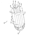
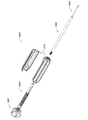
図1は、組織固定デバイス100の一実施形態を示す斜視図である。この実施形態の組織固定デバイス100は、アンカ本体200と、スプレッダ300とを含む。スプレッダ300は、アンカ本体200の中央内腔内に滑動可能に嵌合するように構成される。
FIG. 1 is a perspective view showing an embodiment of the
図1は、拡張または配備された状態の組織固定デバイス100の一実施形態を示す斜視図である。この実施形態の組織固定デバイス100は、アンカ本体200と、スプレッダ300とを含む。スプレッダ300は、アンカ本体200の中央内腔内に滑動可能に嵌合するように構成される。
FIG. 1 is a perspective view showing an embodiment of the
図2Aおよび図2Bにさらに詳細に示すアンカ本体200は、4つのパネル210(すなわち剛性側面部分)を含む。他の実施形態では、例えば3つ、5つ、6つ、7つ、または8つのパネル210など、異なる数のパネル210が存在していてもよい。様々な実施形態では、パネル210が第1の未拡張の位置にあるときには、各パネル210は、少なくとも2辺で隣接するパネル210に当接する。各パネル210は、外側表面212と、内側表面214とを有する。いくつかの実施形態では、これらのパネル210の外側表面212がまとまって、アンカ本体200の形状の少なくとも一部分を画定する。各パネル210の外側表面212は、1つまたは複数の平坦面(例えば面213a、213b、および213c)を含む。このような実施形態では、パネル210が未拡張位置にあるときには、それぞれそれらの外側表面212は、多面体を形成する。他の実施形態では、各パネル210の外側表面212は、曲面を有し、未拡張位置では、これらのパネル210の外側表面212がまとまって円筒を形成する。図2Aのような、他の実施形態では、パネル210は、外側表面212に、曲面213a、213cと非曲面213bとを両方とも有する。様々な実施形態では、パネル210が未拡張位置にあるときには、組織固定デバイス100は流線型位置となり、パネル210の径方向外側に突出する部分が全く存在しないか、それに近い状態になるようになっている。いくつかの実施形態では、パネル210は、実質的に剛性であり、手術中に撓まない。
The
図2Aに示すように、様々な実施形態では、パネル210の内側表面214は、中央内腔265を取り囲み、画定する。さらに、いくつかの実施形態では、各パネル210の内側表面214は、複数の面を有する。例えば、図2Aに示すように、いくつかの実施形態の内側表面214は、少なくとも3つの面(例えば面215a、215b、および215c)を含み、これらがまとまって、溝220を画定する。以下でさらに詳細に述べるように、様々な実施形態では、溝220は、スプレッダ300の突起またはトラックを受けるように構成される。
As shown in FIG. 2A, in various embodiments, the
いくつかの実施形態では、パネル210および中央内腔265は、アンカ本体200のほぼ全長にわたって延びる。そのような実施形態のいくつかでは、アンカ本体200は、パネル210の遠位端部に結合された遠位先端260を含み、これにより、パネル210が実際にはアンカ本体200の全長にわたって延びないようになっている。様々な実施形態では、遠位先端260は、閉じており、丸められている。図2Bに示すように、各パネル210は、ヒンジ要素225を介して遠位先端260に取り付けられる。いくつかの実施形態の遠位先端260は、複数のパネル210を直接的または間接的に接続するための基部として作用する。いくつかの実施形態では、各ヒンジ要素225は、ヒンジ要素225を遠位先端260に枢動接続するヒンジ要素225の遠位側の遠位ピボット224、およびヒンジ要素225をパネル210に枢動接続するヒンジ要素225の近位側の近位ピボット226の、2つの枢動接続部を含む(すなわちダブルヒンジを形成する)。
In some embodiments, the
いくつかの実施形態では、パネル210は、遠位ピボット224および近位ピボット226の周りで枢動することによって未拡張位置から拡張位置に移動するように構成される。様々な実施形態では、パネル210は、スプレッダ300がアンカ本体200の中央内腔265に挿入されたときに未拡張位置から拡張位置に移動するように促される。スプレッダ300は、図3A〜図3Cにさらに詳細に示すように、アンカ本体200のパネル210の変位を容易にするような形状および構成になっている。
In some embodiments, the
図3Aは、スプレッダの近位側斜視図であり、図3Bは、遠位側斜視図であり、図3Cは、スプレッダの断面図である。図3A〜図3Cに示すスプレッダ300は、実質的に筒状の本体310を有し、この筒状本体310の外側表面312上にトラック320が配置されている。いくつかの実施形態のトラック320は、スプレッダ300の遠位側部分からスプレッダ300の近位側部分に外側表面312に沿って長手方向に走っている。いくつかの実施形態では、トラック320は、アンカ本体200の溝220と配置および形状が相補的になっており、溝220内に嵌合するように構成される。溝220およびトラック320は、隆起部321、凹み322、バンプ323、ディンプル、突起、凹部など、トラック320を溝220内にロックするように設計された追加の相補的な特徴を含むこともできる。スプレッダ300のトラック320がアンカ本体200の溝220内にロックされると、アンカ本体200に対するスプレッダ300の軸方向変位および回転が制限される。ロック位置でも、溝220に対してトラック320が長手方向に変位することは依然として可能である。いくつかの実施形態では、これらの相補的な特徴を逆にして、アンカ本体200が1組のトラックまたは突起を含み、スプレッダ300が1組の溝または凹部を含むようにすることもできることは、当業者には理解されるであろう。
3A is a proximal perspective view of the spreader, FIG. 3B is a distal perspective view, and FIG. 3C is a cross-sectional view of the spreader. The
様々な実施形態では、トラック320は、スプレッダ300の長さに沿って管状本体310の外側表面312から不均一な高さを有する。例えば、図3Aおよび図3Bの実施形態などいくつかの実施形態では、各トラック320は、管状本体310から径方向外側に延びるくさび状突起330(以下「くさび」)上に配置される。様々な実施形態では、くさび330は、スプレッダ300の近位端部ではほぼ径方向外側に延び、遠位方向に径方向内側に先細になる。
In various embodiments, the
図3Aには、スプレッダ300の遠位端部でスプレッダ300の内側表面314に沿って円周方向に配置された凹部316(例えば溝)も、示されている。凹部316は、以下でさらに詳細に説明するように、遠位先端260の一部分と係合するように構成される。いくつかの実施形態では、凹部316は、1つまたは複数の屈曲可能タブ318上、またはその内部に位置する。屈曲可能タブ318は、管状本体310の遠位端部に形成された複数の切れ込み319によって画定される。屈曲可能タブは、スプレッダ300がアンカ本体の遠位先端260と接触したときに、切れ込み319の基部から外側に屈曲するように構成される。
FIG. 3A also shows a recess 316 (eg, a groove) located at the distal end of the
さらに、図3Bおよび図3Cで最もよくわかるように、様々な実施形態では、スプレッダ300は、挿入器具を受け、これと結合するように構成された内側チャネル390につながる開口380を有する。挿入器具1000の一実施形態については、以下でさらに詳細に述べる。
In addition, as best seen in FIGS. 3B and 3C, in various embodiments, the
アンカ本体200の遠位先端260の一実施形態を、図4に示す。様々な遠位先端の実施形態では、遠位先端は、実質的に閉じて丸められて、流線型の設計を生じている。この遠位先端260の形状により、アンカ本体200を骨孔内に挿入することが容易になり、アンカ本体200が骨孔内に位置決めされた軟組織の周りの組織を傷つけずに滑動しやすくなる。小孔290を遠位先端260の中央に設けることができ、この小孔290はアンカ本体200と挿入器具との係合を容易にするので有利である。小孔290は、挿入器具の内側ロッド上のスレッドと対合するスレッドに囲まれていてもよい。いくつかの実施形態では、遠位先端260は、スプレッダ300の凹部316と係合するように構成されたリップ262(例えば突出隆起部)を含む。スプレッダ300の凹部316と遠位先端260のリップ262とが係合すると、スプレッダ300の長手方向の移動が制限され、組織固定デバイス100が拡張状態で固定される。アンカ本体の先端は、ヒンジ要素225を遠位ピボット224で遠位先端260に取り付けるための穴、ピン、および/またはその他の特徴266をさらに含むこともできる。
An embodiment of the
図5Aに示すように、様々な実施形態では、スプレッダ300の遠位端部は、アンカ本体200の近位端部で中央内腔265を調心するように構成される。ここに与える図では、スプレッダ300は、中央内腔を既に調心しているが、まだほとんど中央内腔の中に前進してはいない。その結果として、パネル210は、依然として未拡張位置にある。スプレッダ300は、アンカ本体200の溝220の中を滑動することによって、中央内腔中を遠位方向により深く前進し続けるように構成される。スプレッダ300は、図5Bに示すようにスプレッダ300が中央内空中に挿入されたときにアンカ本体200のパネル210を中央内腔265に対して相対的に径方向外側に押し出し、パネル210を拡張位置にするように構成される。
As shown in FIG. 5A, in various embodiments, the distal end of the
アンカ本体200とスプレッダ300とが、スプレッダ300のトラック320が少なくとも部分的にはアンカ本体200の溝220の中に配置されるように位置合わせされた状態で、スプレッダ300を中央内腔中に滑動させると、パネル210は、スプレッダ300の先細部に従って外側に変位する。この外側への変位により、パネル210は互いから分離し、アンカ本体200を拡張させる。様々な実施形態では、パネル210は、枢動して拡張位置になったときに軟組織および骨と係合して、組織固定デバイス100と軟組織とを骨孔内にしっかりと固定するように構成される。図5Bに示すように、様々な実施形態では、各パネル210が拡張位置にあるときには、そのパネル210の全長が外側に変位している。この外側への変位は、近位ピボット226および遠位ピボット224の周りに枢動することによって可能になる。
Sliding the
いくつかの実施形態では、スプレッダ300は、アンカ本体200内を遠位方向に移動すると、前進するくさび330の大きくなっていく直径によってパネル210が外側にさらに押し出されるにつれて、主に近位ピボット226の周りで枢動することになる。このような実施形態のいくつかでは、スプレッダ300は、スプレッダ300の凹部316(図3Cに示す)が遠位先端260のリップ262(図4に示す)と係合するまで、アンカ本体200の中央内空中に挿入することができる。リップ262が凹部316と係合すると、スプレッダ300の遠位端部とヒンジ要素225とが接触し、ヒンジ要素225に力が印加されて、ヒンジ要素225を径方向外側に揺動させ、遠位ピボット224の周りで枢動させる。ヒンジ要素225が遠位ピボット224の周りで外側に揺動すると、パネル210は、完全拡張位置に移行する。このような拡張位置では、パネル210は、アンカ本体200から径方向外側に延びる。いくつかの実施形態では、各パネル210は、パネル210の長さに沿って比較的一様に拡張する。他の実施形態では、図5Bに示すように、パネル210は、遠位端部より近位端部の方がより大きく拡張する。
In some embodiments, the
本明細書に記載する実施形態では、パネル210の外側への変位およびその結果生じるアンカ本体200の拡張は、組織固定デバイス100にいかなるトルクも印加する必要なく行われる。したがって、本明細書に開示する組織固定デバイス100の挿入および拡張は、骨孔内の軟組織の捻れまたは回転を防止する可能性が高いので有利である。
In the embodiments described herein, the outward displacement of the
様々な実施形態では、組織固定デバイス100は、例えば挿入器具3000などの挿入器具を援用して骨孔内に挿入される。挿入器部3000についてのさらなる詳細については後述する。
In various embodiments, the
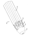
組織固定デバイス1100の別の実施形態を、図6Aに示す。アンカ本体1200は、圧縮可能タブ1220を有する、中央内腔を画定する管状壁1210を備える。一実施形態では、管状壁1210は、一様な直径を有する点で、一様に管状である。圧縮可能タブ1220は、軟組織および骨と係合して、アンカ本体1200および軟組織を骨の中にしっかりと固定するように構成される。いくつかの実施形態では、圧縮可能タブ1220は、組織および骨とさらに係合するように構成された1つまたは複数の歯1230を備える。圧縮可能タブ1220および歯1230の数は変えることができる。圧縮可能タブは、縁部1240に沿って管状壁に固定される。縁部1240は、圧縮可能タブが圧縮状態と拡張状態の間で屈曲可能となるように、管状壁の周りの枢動を可能にするように構成される。組織固定デバイスは、スプレッダ1300も備え、このスプレッダ1300は、アンカ本体の近位端部1250で中央内腔に挿入可能であり、中央内腔に挿入されたときに、圧縮可能タブ1220を管状壁1210に対して相対的に径方向外側に押し出すように構成される。図6Aでは、スプレッダ1300は、未配備または未挿入の状態であり、圧縮可能タブ1220は、潰される圧縮可能状態である。図6Aに示す実施形態では、圧縮可能タブ1220が圧縮状態にあるときには、組織固定デバイス1100は、流線型位置にあり、歯1230が管状壁より径方向外側に全く突出しないか、それに近い状態になっている。
Another embodiment of the
図6Aの組織固定デバイスの実施形態では、組織固定デバイス1100は、外側に拡張可能な最近位部分1205も含む。拡張スロット1206が、アンカ本体1200の近位端部に形成されて遠位方向に延び、外側に拡張可能な近位部分1205が、互いに切り離された複数の拡張可能セグメント1207を備えるようになっている。各拡張可能セグメント1207は、それぞれの遠位端部で、アンカ本体1200の残りの部分(すなわちアンカ本体1200の拡張しない遠位部分)に接続される。図示の実施形態では、拡張可能セグメント1207は、スプレッダ1300がアンカ本体1200の中央内腔1265中で遠位方向に完全に前進したときに、径方向外側に屈曲するように構成される。いくつかの実施形態では、アンカ本体1200の内側表面とスプレッダ1300の隆起部1325とが接触することにより、拡張可能セグメント1207を径方向外側に押し出す力が生じる。
In the tissue fixation device embodiment of FIG. 6A, the
いくつかの実施形態では、組織アンカ1100は、組織アンカ1100が適切なサイズの骨穴内に配置されたときに、外側に拡張可能な最近位部分1205が骨孔の開口付近の骨皮質内に位置決めされるように構成される。このような実施形態では、拡張可能セグメント1207は、皮質中に延びて皮質固定をもたらすように調整することができる。他の実施形態では、拡張可能セグメント1207は、皮質および皮質下の係合を行うように構成することができる。様々な実施形態では、各拡張可能セグメント1207は、拡張可能セグメント1207と周囲の骨との係合を容易にする鋭い縁部、1つまたは複数の隆起部、歯、あるいはその他の突起1208を有する。
In some embodiments, the
組織固定デバイスの一実施形態は、図6Bにも示す。図6Bは、スプレッダ1300がアンカ本体1200の中央内腔に挿入され、それにより圧縮可能タブ1220が拡張位置に移動している斜視図である。このような拡張状態では、歯1230は、アンカ本体1200から径方向外側に延び、骨と係合して、組織固定デバイス1100を骨の中にしっかりと固定する構成になる。図6Bの実施形態では、圧縮可能タブは、円周方向の複数の列に沿って位置決めされる。第1の列1270は、第1の軸方向位置に沿って位置する圧縮可能タブを含み、第2の列1280は、第2の軸方向位置に沿って位置する圧縮可能タブを含む。いくつかの実施形態では、第1の列のタブ1270は、第2の列のタブ1280から円周方向にずれており、2つの圧縮可能タブ1220が同じ長手方向の並びを共有しないようになっている。このような構成により、圧縮可能タブどうしの間で軟組織が滑ることを妨げて、軟組織の捕捉および固定を容易にする。
One embodiment of the tissue fixation device is also shown in FIG. 6B. FIG. 6B is a perspective view in which the
図6Cは、図6Bに示す実施形態の前面図である。図6Cは、拡張状態の圧縮可能タブ1230、および第2の列の圧縮可能タブ1280から円周方向にずれている第1の列の圧縮可能タブ1270を示す。
FIG. 6C is a front view of the embodiment shown in FIG. 6B. FIG. 6C shows the
いくつかの実施形態では、アンカ本体の遠位端部1260は、実質的に丸められて、アンカ本体の骨孔への挿入を容易にし、骨孔内に位置決めされた腱の周りを滑動するようになっている。小孔1290を遠位先端1260の中央に設けることができ、この小孔1290はアンカ本体と挿入器具との係合を容易にするので有利である。この挿入器具については、以降の段落で説明する。小孔1290は、挿入器具の内側ロッド上のスレッドと対合するスレッドを備えることができる。
In some embodiments, the
組織固定デバイスの一実施形態では、複数の圧縮可能タブが同じ軸方向位置に沿って位置づけられて、圧縮可能タブの複数の円周方向列を形成している。図7Aの断面図に示すように、圧縮可能タブは、スプレッダ1300がアンカ本体の近位端部1250から中央内空中に挿入されたときにヒンジ状縁部1240の周りで移動して、圧縮状態から拡張状態に移行する。拡張状態では、圧縮可能タブ1220は、管状壁と実質的に面一になり、歯1230が、アンカ本体から径方向外側に突出する。
In one embodiment of the tissue fixation device, a plurality of compressible tabs are positioned along the same axial position to form a plurality of circumferential rows of compressible tabs. As shown in the cross-sectional view of FIG. 7A, the compressible tab moves around the hinged
組織固定デバイスの別の実施形態では、複数の圧縮可能タブ1220が存在し、全ての圧縮可能タブが、互いに軸方向にずれている。図7Bは、このような実施形態を示す断面図である。圧縮可能タブ1220が軸方向にずれており、2つのタブが同じ軸方向位置に沿って存在することがないので、各タブは、圧縮状態であるときに、中央内腔の中心線または中心軸を越えて延びるように構成することができる。このような構成は、他の多くの実施形態の場合より大きな歯1230を圧縮可能タブに設けて、歯と骨とをより接触しやすくすることができる。
In another embodiment of the tissue fixation device, there are multiple
前段落で述べた一実施形態を、図8Aの斜視図にさらに示す。図8Aでは、アンカ本体1200が単独で示してあり、圧縮可能タブ1220は圧縮または未配備状態になっている。アンカ本体1200は、ほぼ管状または円筒状の形状であり、一様な直径を有する。圧縮可能タブ1220は、屈曲可能縁部1240に沿って内側に屈曲して、歯1230がアンカ本体内の中央内空中に大きく引き込まれて、スプレッダを挿入するまで実質的に管状壁1210を越えて延びないようになっている。圧縮可能タブ1220は、軸方向および円周方向の両方で、互いにずれている。
One embodiment described in the previous paragraph is further shown in the perspective view of FIG. 8A. In FIG. 8A, the
圧縮状態または未配備状態のアンカ本体の別の実施形態を、図8Bの斜視図に示す。図8Bでは、管状壁1210によって画定される中央内腔が、アンカ本体の近位側から見えている。この実施形態のアンカ本体は、スプレッダがアンカ本体に挿入されたときにスプレッダ1300と接触する、管状壁の内側表面1215を有する。いくつかの実施形態では、内側表面1215は滑らかであることもある。他の実施形態では、アンカ本体の内側表面1215およびスプレッダ1300の表面は、滑らかでなく、スプレッダ1300がアンカ本体中に押し込まれた後でスプレッダ1300が動くのを妨げるようにスキャロップ形状または溝を備えるなど、テクスチャを形成することもある。いくつかの実施形態では、内側表面1215のテクスチャは、スプレッダ1300の外側表面のテクスチャと相補的である。このような設計にすると、スプレッダを意図せずに引き込んだり挿入し過ぎたりすることが防止される。いくつかの実施形態では、複数の同心溝、一連の突出隆起部、または任意のその他の相補的な構造など、1つまたは複数の相補的な形状が、アンカ本体1200の内側表面1215およびスプレッダ1300の外側表面上に存在して、アンカ本体1200が完全に配備されたときにスプレッダ1300を適所にロックして、スプレッダ1300を意図せずに引き込んだり挿入し過ぎたりすることを防止することができる。
Another embodiment of the anchor body in the compressed or undeployed state is shown in the perspective view of FIG. 8B. In FIG. 8B, the central lumen defined by the
スプレッダのさらなる詳細を与えるために、スプレッダの実施形態を、図9Aおよび図9Bに示す。スプレッダ1300は、アンカ本体1200の中央内腔に挿入されるように構成された任意の適当な形状を備えることができる。図9Aおよび図9Bの実施形態では、スプレッダの全体として先細の遠位端部1340は、アンカ本体の圧縮可能タブと接触して、スプレッダがアンカ本体に挿入されたときにタブが拡張状態に屈曲するのを容易にするように構成される。スプレッダの本体1310は、一様な環状の形状であり、挿入器具を受けるように構成された軸方向内腔を取り囲む。この実施形態では、スプレッダ1300の管状本体1310は、その近位端部1320の付近に円周方向に位置づけられた隆起部1325を備える。組織固定デバイスが配備されるときに、スプレッダ1300は、アンカ本体1200中に前進し、スプレッダ1300の隆起部1325がアンカ本体の内側表面の溝1225と係合するまで圧縮可能タブ1220を展開させる。一実施形態では、隆起部1325をアンダーカットして、より逆転しにくくなるようにすることができる。スプレッダの近位端部は、おおむね平坦な面と、挿入器具を受ける手段とを備える。例えば、この実施形態では、スプレッダ1300の近位端部1320は、挿入器具を受ける穴1330を備える。配備後、スプレッダは、配備されたアンカ内に留まり、挿入器具の内側ロッドがアンカ本体から剪断されて、スプレッダ1300の近位端部が、アンカ本体1200の近位端部と面一であるか、またはそれよりわずかに凹んだ状態でアンカ内に留まるようになっている。
To give further details of the spreader, embodiments of the spreader are shown in FIGS. 9A and 9B. The
スプレッダ1300は、圧縮可能タブ1220が完全に拡張した位置にある状態で、アンカ本体1200内に留まることになる。圧縮可能タブと、歯と、骨との間の相互作用によって与えられる力が、スプレッダ1300を密に係合した状態に保つ。スプレッダ1300の滑りまたは傾きに対するさらなる保護は、スプレッダ1300の側面を必要に応じて隆起させることによって実現される。一実施形態では、圧縮可能タブ1220のうちの1つまたは複数は、中央内腔に向いている側に凹みを有する。この場合には、スプレッダ1300の隆起部がこの凹みと係合することにより、スプレッダ1300を安定させ、スプレッダ1300がアンカ内で前進し過ぎるのを防止することができる。代替の実施形態では、スプレッダ1300が、圧縮可能タブの中央内腔を向いている側の突起と係合することができる凹みを備える。スプレッダ1300を安定させ、過挿入を防止することに加えて、この特徴は、スプレッダ1300がアンカに対して回転することも防止する。ひねり込んだりねじ込んだりするのではなく、真っ直ぐにスプレッダ1300をアンカ本体1200中に挿入すると、直線運動ではアンカが回転しにくいので、有利である可能性が高い。したがって、直線的な手法は、捕捉した軟組織の捻れまたは回転を防止する可能性が高い。
The
図10Aおよび図10Bに示す一実施形態では、圧縮可能タブは、アンカ本体1200を覆うように位置決めされた滑動可能スリーブ1400によって押し込むことができるように、十分に薄い材料厚さにすることができる。滑動可能スリーブ1400は、アンカ本体1200を骨孔に挿入する間に実質的にアンカ本体1200の内部の適所に圧縮可能タブ1220を保持するように構成される。図10Aは、アンカ本体1200が圧縮状態にあり、アンカ本体と滑動可能スリーブの組合せが挿入器具の外側管1600に接続されている、アンカ本体1200と滑動可能スリーブ1400の組合せの一実施形態を示す図である。滑動可能スリーブ1400は、アンカ本体1200が内腔内の適所にあるときに引っ込めることができ、圧縮可能タブは、少なくとも部分的には拡張することになる。本明細書に記載の方法によれば、挿入器具3000を使用してスプレッダ1300が挿入されたときに、圧縮可能タブおよび歯は完全に拡張することになる。図10Bは、滑動可能スリーブ1400が引き込み状態にあり、アンカ本体1200の圧縮可能タブ1220が部分的に拡張しており、歯1230が管状壁から径方向外側に部分的に突出している、アンカ本体1200と滑動可能スリーブの組合せの一実施形態を示す図である。この図では、スプレッダ1300は、挿入器具3000がアンカ本体1200に挿入される前に、挿入器具3000によってアンカ本体1200に隣接して保持される。
In one embodiment shown in FIGS. 10A and 10B, the compressible tab can be made of a sufficiently thin material thickness so that it can be pushed in by a sliding
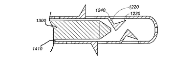
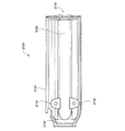
組織固定デバイス2100のさらに別の実施形態を、図11〜図14に示す。上述の組織固定デバイス1100の実施形態と同様に、図11の組織固定デバイス2100の実施形態は、アンカ本体2200と、スプレッダ2300とを備える。スプレッダ2300は、トルクを印加する必要なく、アンカ本体2200の中央内腔2265中に滑動または前進するように構成される。
Yet another embodiment of the
図12に示すように、いくつかの実施形態では、アンカ本体2200は、中央内腔2265を画定する管状壁2210を備える。一実施形態では、管状壁2210は、一様な直径を備える点で、一様に管状である。他の実施形態では、管状壁2210は、遠位側の直径の方が近位側の直径より小さくなるように先細になっている。いくつかの実施形態の先細形状は、組織固定デバイス2100を骨孔に挿入するのを容易にする。いくつかの実施形態では、アンカ本体2200の遠位端部2260は、実質的に丸められ、アンカ本体を骨孔に挿入するのを容易にし、骨孔内に位置決めされた腱の周りで滑動するようになっている。小孔2290を遠位端部2260の中央に設けて、後アンカ本体との段落で説明する挿入器具のような挿入器具との係合を容易にすることができる。小孔2290は、挿入器具の内側ロッド上のスレッドと対合するスレッドを備えることができる。いくつかの実施形態では、アンカ本体2200の近位端部2270を斜めに切断して、管状のアンカ本体の一方の側が別の側より先まで長手方向に延びるようにする。入口に斜めの開口を有する骨孔で使用するときに、このような傾斜を近位端部2270に設けることができる。このような構成により、しばしば行われるように骨に角度をつけて骨孔が穿孔されるときに、アンカ本体2200の近位端部2270を骨の表面と面一にすることができることがある。
As shown in FIG. 12, in some embodiments, the
図12のアンカ本体2200は、外側に拡張可能な近位部分2205も含む。上記のアンカ本体1200の実施形態で述べたように、拡張スロット2206が、アンカ本体2200の近位端部に形成されて遠位方向に延び、外側に拡張可能な近位部分2205が、互いに切り離された複数の拡張可能セグメント2207(すなわち拡張可能側面部分)を備えるようになっている。各拡張可能セグメント2207は、それぞれの遠位端部で、アンカ本体2200の残りの部分(すなわちアンカ本体2200の拡張しない遠位部分)に接続される。拡張可能セグメント2207は、スプレッダ2300がアンカ本体2200の中央内腔2265中で遠位方向に完全に前進したときに、径方向外側に屈曲するように構成される。いくつかの実施形態では、組織アンカ2100は、組織アンカ2100が適切なサイズの骨穴内に配置されたときに、外側に拡張可能な最近位部分2205が骨孔の開口付近の骨皮質内に位置決めされるように構成される。拡張可能セグメント2207は、皮質および/または皮質下の係合を行うように構成することができる。様々な実施形態では、各拡張可能セグメント2207は、拡張可能セグメント2207と周囲の骨との係合を容易にする鋭い縁部、1つまたは複数の隆起部、歯、あるいはその他の突起2208を有する。
The
図12に示すように、いくつかの実施形態では、アンカ本体2200は、アンカ本体2200の遠位側の半分に位置する複数の拡張可能セグメント2220(すなわち拡張可能側面部分)を有する。拡張可能セグメント2220は、スプレッダがアンカ本体2200の中央内腔2265に挿入されたときに、径方向外側に変位する(例えば外側に屈曲する)ように構成される。拡張可能セグメントは、軟組織および骨と係合して、アンカ本体2200および軟組織を骨内にしっかりと固定するように構成される。いくつかの実施形態では、拡張可能セグメント2220は、組織および骨とさらに係合するように構成された1つまたは複数の突起2222(歯、隆起部など)を備える。拡張可能セグメント2220および歯2222の数は変えることができる。拡張可能セグメント2220は、縁部2224に沿って管状壁に固定される。縁部2224は、タイン2222が圧縮状態と拡張状態との間で屈曲可能となるように、管状壁2210の周りの枢動を可能にするように構成される。図12に示す実施形態など、いくつかの実施形態では、拡張可能セグメント2220および縁部2224は、拡張時に拡張可能セグメント2220の遠位端部が最大に変位するような配向および構成になっている。
As shown in FIG. 12, in some embodiments, the
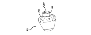
図13は、組織固定デバイス2100のスプレッダ2300を示す図である。いくつかの実施形態では、スプレッダ2300は、円錐状部分2310と、管状部分2320とを含む。他の実施形態では、スプレッダ2300は、全体が管状または円錐状である。いくつかの実施形態では、平坦な溝付き部分2325またはそれと同様の特徴が、スプレッダ2300の外側表面上に存在して、アンカ本体2200の中央内腔2265内の特徴と補完し合い、それにより内腔2265内でスプレッダ2300の配向を整列させる。このような位置合わせの特徴によりスプレッダ2300の軸方向の動きおよび回転運動が制限される。様々な実施形態のスプレッダ2300は、挿入器具を受ける穴2330も含む。
FIG. 13 is a diagram showing a
図14は、拡張状態の組織固定デバイス2100を示す図である。他の実施形態と同様に、スプレッダ2300は、アンカ本体2200の近位端部で中央内腔2265内に挿入することができ、スプレッダ2300が中央内腔に挿入されたときに、拡張可能セグメント2220および拡張可能近位部分2205を管状壁2210に対して径方向外側に押し出すように構成される。近位部分および遠位部分の両方でこのような径方向の拡張が起こることにより、骨孔の近位側開口内および骨孔の遠位側開口内の固定も含めて、組織固定デバイス2100の固定を改善することができる。
FIG. 14 is a diagram showing the
本明細書に開示する組織固定デバイスの様々な実施形態では、組織固定デバイスは、全体が生体適合性のエンジニアリングプラスチックで構成される。他の実施形態は、全体または一部が生体適合性の非金属物質で構成された組織固定デバイスを含む。ポリエーテルエーテルケトン、ポリエーテルケトン、ポリエーテルイミド、超高分子量ポリエチレン、ポリフェニレン、ポリ(ラクチド−co−グリコリド)、ポリカプロラクトン、または何らかのその他の当業者に既知の生体適合性のポリマー材料などの生体適合性のエンジニアリングポリマー材料を、使用することができる。非金属のアンカシステムは、例えばMRIアーチファクトを解消するなど、特定の利点をもたらすことができる。 In various embodiments of the tissue-fixing device disclosed herein, the tissue-fixing device is entirely composed of biocompatible engineering plastics. Other embodiments include tissue fixation devices, all or part of which are composed of biocompatible non-metallic materials. Living organisms such as polyetheretherketone, polyetherketone, polyetherimide, ultrahigh molecular weight polyethylene, polyphenylene, poly (lactide-co-glycolide), polycaprolactone, or any other biocompatible polymeric material known to those skilled in the art. Compatible engineering polymer materials can be used. Non-metal anchor systems can provide certain benefits, such as eliminating MRI artifacts.
図15Aは、いくつかの実施形態において本明細書に開示する任意の組織固定デバイス設計とともに使用することができる挿入器具の個々の構成要素を示す図である。挿入器具3000は、内側ロッドまたは内側管3500と、外側管3600と、ハンドル本体3700と、ねじ付きアクチュエータシャフト3800と、配備ノブ3900とを備える。いくつかの実施形態では、挿入器具3000は、製造中に組織固定デバイス3100に結合される。好ましい実施形態では、挿入器具は使い捨て式である。
FIG. 15A is a diagram showing individual components of an insertion instrument that can be used with any tissue fixation device design disclosed herein in some embodiments. The
挿入器具3000は、上述の組織固定デバイスなどの組織固定デバイスを挿入して操作するように設計される。いくつかの実施形態では、組織固定デバイスは、パッケージングの前に挿入器具に取り付けられるように製造される。その他の実施形態では、組織固定デバイスは、挿入する少し前に挿入器具に結合される。基本構成では、挿入器具は、以下のように組み立てられる。すなわち、挿入器具3000は、内側ロッド3500が外側管3600内に配置されるように構成される。外側管は、スプレッダ3300の近位端部に適合するように構成される。内側ロッド3500は、外側管3600を通って延び、アンカ本体3200の遠位孔のねじおよび内側ロッド3500の遠位端部のねじの両方を介してアンカ本体3200の遠位端部に取り付けられるように構成される。外側管3600の近位端部は、ハンドル3700に接続され、内側ロッド3500は、外側管3600の近位端部を通って延びて、ねじ付きアクチュエータシャフト3800の中に螺入する。アクチュエータシャフト3800は、ハンドル3700の近位端部を越えて延び、そこで配備ノブ3900に固定されるように構成される。
The
挿入器具3000の個々の構成要素について、以下で詳細にさらに説明する。挿入器具3000は、組織固定デバイスの任意の実施形態とともに使用することができる。説明を容易にするために、以下の説明では、挿入器具3000について、組織固定デバイス100を参照して説明する。
The individual components of the
図15Bは、内側ロッド3500の実施形態を示す斜視図である。いくつかの実施形態では、内側ロッドは、内側管である。内側ロッドは、ロッド状または管状の本体3525と、組織固定デバイスのスプレッダ300に固定されるように構成された遠位端部3510と、アクチュエータシャフト3800など、挿入器の他の構成要素と相互作用するように構成された近位端部3520とを備える。内側ロッド3500は、近位端部3520が外側管3600を通ってハンドル3700の中へ前進し、そこでねじを介してアクチュエータシャフト3800内にさらに固定されるように構成される。内側ロッド3500の遠位端部は、スプレッダ300およびアンカ本体200の中央内腔を通って延び、その後アンカ本体200の遠位端部に固定されるように構成される。起動すると、内側ロッドは、組織固定デバイスが完全に配備され、内側ロッドがアンカから分離するまで、引き込まれる。
FIG. 15B is a perspective view showing an embodiment of the
内側ロッド3500は、スプレッダ300およびアンカ本体200の中央内腔を通って延びた後で、アンカ本体200の遠位端部に結合される。一実施形態では、内側ロッド3500は、内側ロッド3500の端部のねじ3505およびアンカ本体200の遠位端部内のねじを介してアンカ本体200と結合される。他の実施形態では、内側ロッド3500は、接着剤、溶接、または摩擦嵌めなど、その他の固定機構を介してアンカ本体200に結合することもできる。
The
図15Cは、外側管3600の実施形態を示す図である。外側管3600は、その近位端部3605で、ねじ3625を介してハンドル3700の遠位端部に取り付けられる。外側管3600の遠位端部3610は、内側ロッド3500を外側管3600の遠位端部3610を通って外側管3600の中に引き込むことができるように構成される。内側管3500が、スプレッダ300が適所にロックされるのに十分な距離を前進したとき、またはそれ以上前進することができなくなったとき、外側管3600の遠位表面は、アンカ本体200の近位表面と同じ高さになることができる。配備ノブを引き続き回転させ、アクチュエータシャフトを前進させて、内側ロッド3500がさらに外側管の中に引き込まれると、内側ロッド3500がアンカ本体200のねじをすり潰し、挿入器具3000が組織固定デバイス100から離れる。
FIG. 15C is a diagram showing an embodiment of the
図15Dおよび図15Eは、ハンドル本体3700の実施形態を示す図である。図15Dは、ハンドル3700の一実施形態を示す断面図であり、図15Eは、ハンドル本体3700を示す切断図である。ハンドル3700の近位端部は、ノブ3900をしっかりと保持する隆起部3730を介して配備ノブ3900を受けるように構成される。アクチュエータシャフト3800は、ハンドル本体3700の中に収容される。それぞれ平坦な表面3715を有する1組のブラケットまたはブレース3710が、アクチュエータシャフト3800をハンドル3700内に固定する。ハンドルの遠位端部3770は、開口3740においてねじ3725を介して外側管3600を受けるように構成される。外側管3600は、その遠位端部においてハンドル3700に永続的に固定される。
15D and 15E are views showing an embodiment of the
図15Fは、ねじ付きアクチュエータシャフト3800を示す図である。アクチュエータシャフト3800は、内側ロッド3500を受けるように構成されたねじ穴3810を備えた遠位端部3805と、内側ロッド3500を前進させるように構成されたシャフトの本体の第2のねじ部3825と、配備ノブ3900内に固定されるように構成された近位端部3820とで構成される。アクチュエータ3800のねじ3825は、各面に1つずつ2つの平坦領域3830を有し、この平坦表面には、ねじはない。これらの平坦領域3830は、アクチュエータ3800がハンドル内で回転することができないように、ハンドルの平坦ブラケット3710の内側に嵌合する。
FIG. 15F is a diagram showing a threaded
アクチュエータシャフト3800の本体は、シャフト3800が内側管3500を前進させることができるようにするねじ3825を有する構成である。アクチュエータシャフト3800の本体は、完全な円形ではなく、配備ノブ3900が回されて、シャフト3800がノブ3900を介して前進したときにアクチュエータシャフト3800自体が回転することができないようにハンドル本体3700に嵌合する平坦な側面3830を有する長円形である。したがって、ねじは、シャフトの全周に形成されるのではなく、シャフトの平坦側面で平坦になっている。アクチュエータシャフトは、同軸システムとして構成される。すなわち、スプレッダ3300と、内側管3500と、アクチュエータ3800とが、1つのピースとして動作するように構成される。ハンドル内の平坦ブラケット3710によって、ハンドル3700内でアクチュエータシャフト3800自体が回転することができないように、アクチュエータシャフト3800は面上に留まる。内側管3500の近位端部は、ねじを介してアクチュエータシャフト3800の遠位端部と結合する。
The body of the
図15Gは、配備ノブ3900を示す図である。配備ノブ3900は、ねじ3905を有する構成の中央穴3910と、ハンドル3700の対応する隆起部3730によって受けられるように構成された溝3930とを備える。中央穴3910の中のねじ3905は、アクチュエータシャフト3800を受けるように構成される。配備ノブ3900は、アクチュエータシャフト3800を介して内側ロッド3500を配備ノブ3900に対して相対的に前進させるように構成される。アクチュエータシャフト3800は、その近位端部において、配備ノブ3900の遠位端部に中央穴3910の中のねじ3905を介して結合される。アクチュエータシャフト3800は、内側ロッド3500の近位端部がアクチュエータシャフトの遠位端部の中へねじを介して進入することによって内側ロッド3500に取り付けられ、配備ノブ3900が回転したときにシャフト3800の機構が内側ロッド3500を近位方向に前進させ、スプレッダ300がアンカ本体200の中へ進入して、アンカ本体200を骨の中へ拡張させ、組織固定デバイス100を固定するようになっている。
FIG. 15G is a diagram showing a
一実施形態では、配備ノブ3900は、ねじ3905を有し、ノブ3900の溝3930がハンドル本体3700の近位端部の隆起部3730と嵌合することによってアクチュエータシャフトを受ける。配備ハンドルが回転すると、アンカ本体200が配備されて適所にロックされるまで、アクチュエータシャフト3800が近位方向に前進する。
In one embodiment, the
配備のための位置にあるときには、内側ロッド3500は、外側管3600内に位置決めされ、外側管は、アンカ本体200と面一になっている。内側ロッド3500は、挿入および配備の間、アンカ本体200を安定して保持することができる。内側ロッド3500は、スプレッダ300を通って延び、ねじを介してアンカ本体200と結合される。スプレッダ300は、配備ノブ3900を回転させることによって内側ロッド3500が引き込まれることによってアンカ本体200の近位端部を通って遠位方向に前進し、これによりアンカ本体200がスプレッダ300より近位方向に引っ張られるように構成される。
When in position for deployment, the
外側管3600は、スプレッダ300をアンカ本体200の中央内腔265の中に押し込んで、アンカ本体200を完全に拡張させる機構を提供する。組織固定デバイスの配備中、内側ロッド3500は、スプレッダ300がアンカ本体200内にロックされるまでねじ運動によって継続的に引き込まれる。配備ノブ3900が回転し続け、内側ロッド3500がアンカ本体200のねじを引っ張り続けると、内側ロッド3500は、アンカ本体200の内側のねじをすり潰し、挿入器具3000はアンカ本体200から外れる。ねじの削り屑は、外側管3600の中に収容される。
The
いくつかの実施形態では、予め取り付けられた送出しハンドルが設けられる。いくつかの実施形態では、挿入器具または送出しハンドルは、使い捨て式である。他の実施形態では、挿入器具は、殺菌し、リロードし、再使用することができる。 In some embodiments, a pre-installed delivery handle is provided. In some embodiments, the insertion device or delivery handle is disposable. In other embodiments, the insert can be sterilized, reloaded and reused.
当業者なら、本明細書に記載する組織固定アンカを挿入して配備するために使用することができる他の挿入器および機構を認識するであろう。組織固定デバイスを挿入して操作する特定の挿入デバイスについて説明したが、他の挿入器の設計を使用して、上述の組織固定デバイスを操作して、アンカおよび軟組織を骨に挿入することができることを理解されたい。例えば、アンカの挿入と、軟組織の固定と、アンカの固定とで、別個の器具を使用することができることもある。 Those skilled in the art will recognize other inserters and mechanisms that can be used to insert and deploy the tissue fixative anchors described herein. Although specific insertion devices have been described for inserting and manipulating tissue fixation devices, other inserter designs can be used to manipulate the tissue fixation devices described above to insert anchors and soft tissues into bone. I want you to understand. For example, separate instruments may be used for anchor insertion, soft tissue fixation, and anchor fixation.
上述のアンカは、ACLの修復において組織移植片を固定するために使用することができる。いくつかの実施形態では、上述のアンカを使用して、組織を脛骨の骨孔内に固定する。このような手順では、組織移植片は、最初に大腿骨の骨孔内に固定する。任意の適当なアンカを使用して、組織を大腿骨に固定することができる。いくつかの実施形態では、適当なアンカは、組織を捕捉して、脛骨および/または大腿骨の骨孔を通してこの組織を送るために使用することができる、組織把持特徴を含む。いくつかの実施形態では、組織把持特徴は、1つまたは複数の組織束の周りに締め付けることができる縫合糸ループを含む。 The anchors described above can be used to secure tissue implants in ACL repair. In some embodiments, the anchors described above are used to secure the tissue within the tibial foramen. In such a procedure, the tissue implant is first fixed in the foramen of the femur. Any suitable anchor can be used to secure the tissue to the femur. In some embodiments, a suitable anchor comprises a tissue gripping feature that can be used to capture tissue and send it through the foramen of the tibia and / or femur. In some embodiments, the tissue gripping feature comprises a suture loop that can be tightened around one or more tissue bundles.
このような縫合糸ループアンカ4000の一例を、図16Aおよび図16Bに示すが、これについては、参照によりその全体を本明細書に組み込む、特許文献1の図13A〜図16Bにさらに詳細に示されている。図16Aは、組織を捕捉する準備ができた縫合糸ループを有する、未配備状態の大腿骨アンカ4000を示す図である。組織を捕捉し、大腿骨に挿入した後で、アンカ4000上の側方突起を配備して、アンカおよび組織を大腿骨内に固定することができる。図16Bは、配備状態の大腿骨アンカ4000を示す図である。
An example of such a
他の実施形態では、上述の脛骨アンカの修正形態を、大腿骨アンカとして使用することができる。大腿骨アンカ5000のこのような実施形態の1つを、図17に示す。この場合には、丸められた遠位端部の代わりに、アンカ本体5100は、平坦な形状、凹んだ形状、またはサドル形状の遠位端部5106を備える。遠位端部5106には2つの開口が設けられ、そこに縫合糸を通して、遠位端部に縫合糸ループ5200を形成する。図16Aおよび図16Bに示すアンカと同様に、縫合糸ループ5200内に組織を捕捉し、縫合糸を締め、その後、組織を捕捉したアンカ5000を大腿骨の骨孔に挿入することができる。アンカ5000は、脛骨アンカについて上述したのと同じスプレッダおよび挿入器を用いて配備することができる。
In other embodiments, the modified form of the tibial anchor described above can be used as the femoral anchor. One such embodiment of the
当業者なら、断裂したACLの修復を行う際に本明細書に記載した脛骨アンカと組み合わせて使用されるその他の適当な大腿骨アンカを理解するであろう。 One of ordinary skill in the art will understand other suitable femoral anchors used in combination with the tibial anchors described herein in performing repair of a torn ACL.
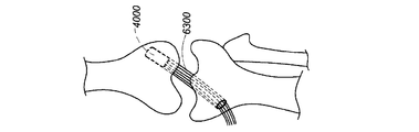
図18A〜図18Dは、本明細書に記載するアンカを利用する、いくつかの非限定的な適当なACL修復技術を示す図である。最初に、図18Aに示すように、脛骨に骨孔6100が形成され、大腿骨に骨孔6200が形成される。いくつかの実施形態では、骨孔6100および6200は両方とも、脛骨に穿孔し、次いで大腿骨に穿孔する、1つのドリルを用いて形成される。他の実施形態では、大腿骨孔6200と脛骨孔6100は、別々に形成することもできる。次に、外科医は、患者の腱(例えば1つまたは複数の膝蓋筋または腿筋の腱)、死体の腱、または人工移植片を含むこともある、適当な組織移植片6300を取得する。次いで、組織移植片6300を、例えば図16A〜図17に示すアンカ4000、5000のうちのいずれかなどの大腿骨アンカ1100で捕捉する。次いで、大腿骨アンカ4000(一例)を大腿骨孔6200に挿入し、配備して、移植片6300を大腿骨中に固定する。
18A-18D are diagrams showing some non-limiting suitable ACL repair techniques utilizing the anchors described herein. First, as shown in FIG. 18A, a
一実施形態では、図18Bに示すように、外科医は、組織移植片6300を捕捉した大腿骨アンカ4000を大腿骨と脛骨の間のスペースに側方から挿入する、側方技術を使用する。次いで、大腿骨アンカ4000を、大腿骨孔6200に直接挿入する。関節を外転させて、大腿骨孔6200への直接挿入を容易にすることもできる。大腿骨アンカ4000を挿入した後で、組織移植片6300を、脛骨孔6100を通して送り、反対側から外に出して、図18Cに示す構成にすることができる。1つの技術では、縫合糸ループを脛骨孔6100に通して送り、移植片6300をループに通して送り、次いで、脛骨孔6100を通してループを引っ張って、それと一緒に移植片6300を引っ張る。
In one embodiment, as shown in FIG. 18B, the surgeon uses a lateral technique in which the
代替の実施形態では、組織移植片6300を捕捉した大腿骨アンカ4000を脛骨孔6100に挿入し、次いで大腿骨孔6200中へ挿入する、インライン(in−line)手法を使用することができる。その結果として、移植片6300は、図18Cに示すように、大腿骨アンカ4000から脛骨孔6100を通り、脛骨孔6100から出る。
In an alternative embodiment, an in-line technique can be used in which the
図18Cの構成になった後で、関節を位置決めし、組織移植片6300に適当に張力を掛けることができる。次に、図18Dに示すように、本明細書に記載する脛骨アンカ(例えば脛骨アンカ100)を、脛骨孔6100の開口中に挿入し、配備して、移植片6300を脛骨に固定することができる。次いで、余分な移植片6300をトリミングして、脛骨アンカ100と面一になるようにすることができる。図18Dに示すように、いくつかの実施形態では、脛骨アンカ100は、実質的に脛骨孔6100の全長に沿って延びるように構成される。本明細書に開示する組織固定デバイス100のいくつかの実施形態では、脛骨アンカ100の拡張は、比較的一様である。他の実施形態では、組織固定デバイスは、脛骨アンカ100の長さに沿った様々な位置で拡張するように構成される。したがって、上述の脛骨アンカのうちのいずれかをACL修復手順に使用すると、脛骨孔6100の全長にわたって組織を骨に固定することができるので有利であることがある。様々な実施形態では、アンカの長さは、約30mmより長いか、約35mmより長いか、約40mmより長いか、または約45mmである。
After the configuration shown in FIG. 18C, the joint can be positioned and the
ACL修復方法の一実施形態では、脛骨アンカ100を、脛骨孔6100の開口中に挿入し、脛骨アンカ100の少なくとも遠位先端が脛骨孔6100の反対側から出るまで、遠位方向に押し込むことができる。このような実施形態では、次いで、脛骨アンカ100を、脛骨アンカ100の遠位先端が見えなくなるまで、近位方向に引き戻す。このような挿入機構は、脛骨アンカ100が脛骨孔6100の実質的に全長にわたって延びるように、脛骨アンカ100が適切なサイズになり、骨孔内に配置されることを保証する。いくつかの実施形態では、このように配置することにより、脛骨孔6100の遠位開口および近位開口の両方で、脛骨アンカ100を開口固定することができるようになる。
In one embodiment of the ACL repair method, the
あるいは、またはこれに加えて、ACL修復方法の一実施形態では、脛骨孔6100を測定して、その長さを決定する。いくつかのこのような実施形態では、測定器具またはガイドを、形成後の脛骨孔6100に挿入する。骨孔6100の長さを検出し、骨孔6100の実質的に全長に適合する適当なサイズの脛骨アンカ(例えば脛骨アンカ100)を選択する。次いで、図18B〜図18Dに関連して説明した方法に従って、アンカおよび組織を挿入する。いくつかのこのような実施形態では、25mm超の長さを有するアンカを選択する。いくつかの実施形態では、約30mm、45mm、50mm、またはそれらの間の任意の値の長さを有するアンカを選択する。
Alternatively, or in addition to this, in one embodiment of the ACL repair method, the
脛骨孔6100の遠位開口および近位開口の両方の開口固定は、脛骨アンカ100(およびその結果として組織6300)をその両端で海綿質骨および皮質骨の両方と係合することを可能にする可能性があるので、有利である。脛骨のより軟らかい外側骨部分内に固定すると、アンカ100および組織の周りの骨の成長をより良好にし、両端の安定した接続を保証することができる。いくつかの実施形態では、遠位側および近位側の両方における脛骨アンカの開口固定は、組織6300の摩耗および刺激を最小限に抑える助けとなる。これにより、アンカの一方の端部が緩んでいるときに発生する可能性がある「ウィンドシールドワイパ(windshield wiper)」効果を低減することができる。また、組織6300と脛骨との間の接触を増加させることにより、治癒プロセスを改善し、アンカが故障するリスクを低下させることができる。
Opening fixation of both the distal and proximal openings of the
いくつかの実施形態では、上述の手法は、単一の組織移植片6300の束を使用して行われる。この場合には、移植片6300を大腿骨アンカ4000で捕捉し、大腿骨アンカ4000の端部の上で折り返して、移植片6300の2つの平行な部分が大腿骨アンカ4000から脛骨アンカ100に延びるようにすることができる。他の実施形態では、2つの組織移植片6300の束を大腿骨アンカ4000の端部の上で折り返して、移植片6300の4つの平行な部分が大腿骨アンカ4000から脛骨アンカ100に延びるようにすることができる。
In some embodiments, the technique described above is performed using a bundle of
本明細書では、ACL修復技術について説明したが、説明したアンカは、外科医が軟組織を骨に固定したいと思う任意数の手順で使用することができることは理解されるであろう。 Although ACL repair techniques have been described herein, it will be appreciated that the anchors described can be used in any number of procedures in which the surgeon wants to fix the soft tissue to the bone.
本開示を概説するために、本明細書では、特定の態様、利点、および特徴について説明した。任意の特定の実施形態で、必ずしもこれらの利点が全て実現されなくてもよいことは理解されるであろう。したがって、本発明は、本明細書に教示または提示されている場合もある他の利点を必ずしも実現せずに、本明細書に教示される1つの利点または一群の利点を実現または最適化する方法で、実施または実行され得る。 To outline this disclosure, specific aspects, advantages, and features have been described herein. It will be appreciated that in any particular embodiment, not all of these benefits need to be realized. Accordingly, the present invention is a method of achieving or optimizing one or a group of benefits taught herein, without necessarily realizing the other benefits that may be taught or presented herein. Can be implemented or implemented.
現在実用的な実施形態であると考えられる実施形態に関連付けて本発明について説明したが、本開示の範囲を逸脱することなく、様々な修正および変更を加えることができることは、当業者には理解されるであろう。また、1つの実施形態と混合される部分は、他の実施形態と入れ替え可能である、すなわち、図示の実施形態の1つまたは複数の部分を、任意の組合せで他の図示の実施形態に含めることもできることも、当業者には理解されるであろう。例えば、本明細書に記載し、かつ/または図面に示す様々な構成要素のうちの任意の構成要素を、結合し、入れ替え、または他の実施形態から排除することができる。本明細書の実質的に全ての複数形の用語および/または単数形の用語の使用について、当業者なら、文脈および/または適用分野に即して複数から単数に、かつ/または単数から複数に変換することができる。本明細書では、わかりやすくするために、様々な単数形/複数形の入れ替えが明確に記載されていることもある。 Although the present invention has been described in connection with embodiments that are currently considered to be practical embodiments, those skilled in the art will appreciate that various modifications and modifications can be made without departing from the scope of the present disclosure. Will be done. Also, the portion mixed with one embodiment is interchangeable with other embodiments, i.e., one or more portions of the illustrated embodiment are included in the other illustrated embodiment in any combination. Those skilled in the art will understand that they can and can do it. For example, any component of the various components described herein and / or shown in the drawings can be combined, swapped, or excluded from other embodiments. For the use of substantially all plural and / or singular terms herein, one of ordinary skill in the art will appreciate the context and / or application from plural to singular and / or from singular to plural. Can be converted. In the present specification, various singular / plural interchanges may be clearly described for the sake of clarity.
本開示では、特定の例示的な実施形態について説明したが、本発明は、開示した実施形態に限定されず、限定されるどころか、添付の特許請求の範囲およびその均等物の範囲内に含まれる様々な修正形態および等価な構成をカバーするように意図されていることを理解されたい。
以下の項目は、出願当初の特許請求の範囲に記載の要素である。
(項目1)
前十字靱帯(ACL)修復方法であって、
脛骨に骨孔を形成するステップであり、前記骨孔が、前記脛骨の一方の側の近位開口、および前記脛骨の反対側の遠位開口を備えるステップと、
前記骨孔に軟組織を通すステップと、
前記軟組織を大腿骨に固定するステップと、
前記骨孔の近位開口に、アンカの遠位端部が前記骨孔の遠位開口に隣接する位置までアンカを挿入するステップであり、前記アンカが、内部空洞を有する拡張可能なアンカ本体、およびスプレッダを備えるステップと、
エキスパンダを前記内部空洞中に滑動させることにより、前記アンカ本体の少なくとも一部分を外側に拡張させるステップであり、前記拡張が完了したときに、前記骨孔の前記遠位開口に隣接する前記アンカ本体の少なくとも一部分が拡張するステップと、
を含むことを特徴とする方法。
(項目2)
前記アンカが挿入されたとき、前記アンカが前記骨孔の実質的に全長にわたって延びる、項目1に記載の方法。
(項目3)
前記アンカが拡張したときに、前記アンカの少なくとも一部分が外側に拡張しない、項目1に記載の方法。
(項目4)
外側に拡張しない部分が、アンカ先端を備える、項目3に記載の方法。
(項目5)
前記アンカが、約30mmを超える長さである、項目1に記載の方法。
(項目6)
前記アンカが、約35mmを超える長さである、項目1に記載の方法。
(項目7)
前記アンカが、約40mmを超える長さである、項目1に記載の方法。
(項目8)
前十字靱帯(ACL)修復方法であって、
脛骨に骨孔を形成するステップであり、前記骨孔が、前記脛骨の一方の側の近位開口、および前記脛骨の反対側の遠位開口を備えるステップと、
前記骨孔に軟組織を通すステップと、
前記軟組織を大腿骨に固定するステップと、
前記骨孔の近位開口に、アンカの遠位端部が前記骨孔の遠位開口に隣接する位置までアンカを挿入するステップであり、前記アンカが、内部空洞を有する拡張可能なアンカ本体、およびスプレッダを備えるステップと、
エキスパンダを前記内部空洞中に挿入することにより、前記アンカ本体の少なくとも一部分を外側に拡張させるステップであり、前記拡張が完了したときに、前記アンカ本体の前記拡張した部分が、その長さに沿って実質的に一様に拡張するステップと、
を含むことを特徴とする方法。
(項目9)
前記アンカが挿入されたとき、前記アンカが前記骨孔の実質的に全長にわたって延びる、項目8に記載の方法。
(項目10)
前記アンカが拡張したときに、前記アンカの少なくとも一部分が外側に拡張しない、項目8に記載の方法。
(項目11)
外側に拡張しない前記部分が、アンカ先端を備える、項目10に記載の方法。
(項目12)
前記アンカが、約30mmを超える長さである、項目8に記載の方法。
(項目13)
前記アンカが、約35mmを超える長さである、項目8に記載の方法。
(項目14)
前記アンカが、約40mmを超える長さである、項目8に記載の方法。
(項目15)
前十字靱帯(ACL)修復方法であって、
脛骨に骨孔を形成するステップであり、前記骨孔が、前記脛骨の一方の側の近位開口、および前記脛骨の反対側の遠位開口を備えるステップと、
前記骨孔に軟組織を通すステップと、
前記軟組織を大腿骨に固定するステップと、
前記骨孔の長さを測定するステップと、
前記測定に基づいて、複数の可能なアンカからアンカを選択するステップと、
前記骨孔の近位開口に、前記アンカの遠位端部が前記骨孔の遠位開口に隣接する位置まで前記アンカを挿入するステップであり、前記アンカが、内部空洞を有する拡張可能なアンカ本体、およびスプレッダを備えるステップと、
前記スプレッダを前記内部空洞中に挿入することにより、前記アンカ本体の少なくとも一部分を外側に拡張させるステップであり、前記拡張が完了したときに、前記骨孔の前記遠位開口に隣接する前記アンカ本体の少なくとも一部分が拡張するステップと、
を含むことを特徴とする方法。
(項目16)
前記アンカを選択するステップが、複数の可能な長さからアンカの長さを選択するステップを含む、項目15に記載の方法。
(項目17)
拡張可能骨アンカであって、
遠位先細なアンカ先端、および
ダブルヒンジを介してそれぞれ前記アンカ先端に結合される、前記アンカ先端から近位方向に延びる複数の剛性側面部分
を備えるアンカ本体と、
前記アンカ本体中へ遠位方向に前進することにより、前記剛性側面部分を外側に拡張させるように構成されたスプレッダと、
を備えることを特徴とする拡張可能骨アンカ。
(項目18)
前記スプレッダが、前記剛性側面部分に結合される、項目17に記載のアンカ。
(項目19)
前記スプレッダが、前記剛性側面部分に滑動可能に結合される、項目17に記載のアンカ。
(項目20)
前記スプレッダが、複数の長手方向トラックを備え、各側面部分が、前記側面部分が前記長手方向トラックに沿って長手方向に滑動することができるように、前記長手方向トラックのうちの1つに結合される、項目19に記載のアンカ。
(項目21)
前記スプレッダが、遠位方向に先細になっている少なくとも一部分を備える、項目17に記載のアンカ。
(項目22)
前記アンカ先端が、近位ロック部材を備え、前記スプレッダが、遠位ロック部材を備え、前記2つのロック部材が、前記スプレッダが遠位方向に最大限まで前進したときに互いにロックするように構成される、項目17に記載のアンカ。
(項目23)
前記アンカ先端の前記近位ロック部材が、外側に突出する隆起部を有するポストを備え、前記スプレッダの前記遠位ロック部材が、前記ポストを受けるように構成された中空円筒を備える、項目22に記載のアンカ。
(項目24)
前記中空円筒が、前記隆起部を受けるように構成された、内側表面上の溝を備える、項目23に記載のアンカ。
(項目25)
前記中空円筒が、拡張可能タブを備える、項目24に記載のアンカ。
(項目26)
最大限に拡張したときに、前記剛性側面部分が、その長さに沿って実質的に一様な程度に拡張する、項目17に記載のアンカ。
(項目27)
拡張可能骨アンカであって、
遠位先細なアンカ先端、
アンカ本体の近位端部に位置決めされた複数の第1の拡張可能側面部分であり、遠位部分より近位部分でより大きく外側に延びるように外側に屈曲することによって拡張する第1の拡張可能側面部分、および
前記第1の拡張可能側面部分より遠位側に位置決めされた複数の第2の拡張可能側面部分であり、近位部分より遠位部分でより大きく外側に延びるように外側に屈曲することによって拡張する第2の拡張可能側面部分
を備えるアンカ本体と、
前記アンカ本体中へ遠位方向に前進することによって、前記第1の拡張可能側面部分および前記第2の拡張可能側面部分を外側に拡張させるように構成されたスプレッダと、
を備えることを特徴とする拡張可能骨アンカ。
(項目28)
前記第1の拡張可能側面部分および前記第2の拡張可能側面部分が、骨と係合する特徴を備える、項目27に記載のアンカ。
(項目29)
前記骨と係合する特徴が、歯を備える、項目28に記載のアンカ。
(項目30)
前記骨と係合する特徴が、隆起部を備える、項目28に記載のアンカ。
(項目31)
前記第1の拡張可能側面部分および前記第2の拡張可能側面部分が、前記アンカ本体の側壁の切れ込みによって形成される、項目27に記載のアンカ。
(項目32)
前記スプレッダが、遠位方向に先細になっている少なくとも一部分を備える、項目27に記載のアンカ。
(項目33)
前記スプレッダが、その長さに沿って実質的に一定の直径を有する、項目27に記載のアンカ。
(項目34)
前記スプレッダが、その近位端部に、またはその近位端部に隣接して位置決めされた円周方向隆起部を備える、項目33に記載のアンカ。
(項目35)
前記アンカ本体が、実質的にその全長にわたって遠位方向に先細になっている、項目31に記載のアンカ。
(項目36)
前記アンカ先端が、半球形状を有する、項目31に記載のアンカ。
(項目37)
前記アンカ先端が、円錐形状を有する、項目31に記載のアンカ。
(項目38)
前記第2の拡張可能側面部分が、前記アンカ本体内の中央空洞中に延びる突起を備え、前記スプレッダが前記中央空洞中へ前進することによって、前記スプレッダが前記突起と接触し、それにより前記第2の拡張可能側面部分を外側に拡張させる、項目31に記載のアンカ。
Although specific exemplary embodiments have been described in the present disclosure, the present invention is not limited to the disclosed embodiments, but is included within the scope of the appended claims and their equivalents. It should be understood that it is intended to cover various modifications and equivalent configurations.
The following items are the elements described in the claims at the time of filing.
(Item 1)
Anterior cruciate ligament (ACL) repair method
A step of forming a bone hole in the tibia, wherein the bone hole comprises a proximal opening on one side of the tibia and a distal opening on the opposite side of the tibia.
The step of passing soft tissue through the bone hole and
The step of fixing the soft tissue to the femur,
A step of inserting an anchor into the proximal opening of the bone hole to a position where the distal end of the anchor is adjacent to the distal opening of the bone hole, wherein the anchor is an expandable anchor body having an internal cavity. And steps with spreaders,
It is a step of expanding at least a part of the anchor body outward by sliding the expander into the internal cavity, and when the expansion is completed, the anchor body adjacent to the distal opening of the bone hole. And the steps that at least part of
A method characterized by including.
(Item 2)
The method of item 1, wherein when the anchor is inserted, the anchor extends substantially the entire length of the bone hole.
(Item 3)
The method according to item 1, wherein at least a part of the anchor does not expand outward when the anchor expands.
(Item 4)
The method according to
(Item 5)
The method according to item 1, wherein the anchor has a length exceeding about 30 mm.
(Item 6)
The method of item 1, wherein the anchor has a length of more than about 35 mm.
(Item 7)
The method of item 1, wherein the anchor has a length of more than about 40 mm.
(Item 8)
Anterior cruciate ligament (ACL) repair method
A step of forming a bone hole in the tibia, wherein the bone hole comprises a proximal opening on one side of the tibia and a distal opening on the opposite side of the tibia.
The step of passing soft tissue through the bone hole and
The step of fixing the soft tissue to the femur,
A step of inserting an anchor into the proximal opening of the bone hole to a position where the distal end of the anchor is adjacent to the distal opening of the bone hole, wherein the anchor is an expandable anchor body having an internal cavity. And steps with spreaders,
It is a step of expanding at least a part of the anchor body to the outside by inserting the expander into the internal cavity, and when the expansion is completed, the expanded part of the anchor body reaches its length. With steps that extend virtually uniformly along
A method characterized by including.
(Item 9)
8. The method of item 8, wherein when the anchor is inserted, the anchor extends substantially the entire length of the bone hole.
(Item 10)
8. The method of item 8, wherein when the anchor expands, at least a portion of the anchor does not expand outward.
(Item 11)
The method of item 10, wherein the portion that does not extend outward comprises an anchor tip.
(Item 12)
The method of item 8, wherein the anchor has a length of more than about 30 mm.
(Item 13)
The method of item 8, wherein the anchor has a length of more than about 35 mm.
(Item 14)
The method of item 8, wherein the anchor has a length of more than about 40 mm.
(Item 15)
Anterior cruciate ligament (ACL) repair method
A step of forming a bone hole in the tibia, wherein the bone hole comprises a proximal opening on one side of the tibia and a distal opening on the opposite side of the tibia.
The step of passing soft tissue through the bone hole and
The step of fixing the soft tissue to the femur,
The step of measuring the length of the bone hole and
A step of selecting an anchor from a plurality of possible anchors based on the above measurement,
A step of inserting the anchor into the proximal opening of the bone hole to a position where the distal end of the anchor is adjacent to the distal opening of the bone hole, wherein the anchor is an expandable anchor having an internal cavity. With the main body and the steps with the spreader,
It is a step of expanding at least a part of the anchor body outward by inserting the spreader into the internal cavity, and when the expansion is completed, the anchor body adjacent to the distal opening of the bone hole. With steps that at least part of
A method characterized by including.
(Item 16)
The method of item 15, wherein the step of selecting the anchor comprises selecting the length of the anchor from a plurality of possible lengths.
(Item 17)
An expandable bone anchor
Distal tapered anchor tip, and
A plurality of rigid side portions extending proximally from the anchor tip, each coupled to the anchor tip via a double hinge.
Anchor body with
A spreader configured to extend the rigid side surface outward by advancing distally into the anchor body.
An expandable bone anchor characterized by being equipped with.
(Item 18)
17. The anchor according to item 17, wherein the spreader is coupled to the rigid side surface portion.
(Item 19)
17. The anchor according to item 17, wherein the spreader is slidably coupled to the rigid side surface portion.
(Item 20)
The spreader comprises a plurality of longitudinal tracks, each side portion coupled to one of the longitudinal tracks so that the side portion can slide longitudinally along the longitudinal track. The anchor according to item 19.
(Item 21)
17. The anchor according to item 17, wherein the spreader comprises at least a portion that tapers distally.
(Item 22)
The anchor tip comprises a proximal locking member, the spreader comprises a distal locking member, and the two locking members are configured to lock each other when the spreader is maximally advanced in the distal direction. The anchor according to item 17.
(Item 23)
Item 22, wherein the proximal locking member at the anchor tip comprises a post having a ridge protruding outward, and the distal locking member of the spreader comprises a hollow cylinder configured to receive the post. The anchor described.
(Item 24)
23. The anchor according to item 23, wherein the hollow cylinder comprises a groove on the inner surface configured to receive the ridge.
(Item 25)
24. The anchor according to item 24, wherein the hollow cylinder comprises an expandable tab.
(Item 26)
17. The anchor according to item 17, wherein when maximally expanded, the rigid side portion expands to a substantially uniform degree along its length.
(Item 27)
An expandable bone anchor
Distal tapered anchor tip,
A plurality of first expandable side portions positioned at the proximal end of the anchor body, the first extension that expands by bending outward to extend more outward in the proximal portion than the distal portion. Possible side parts, and
A plurality of second expandable side portions positioned distal to the first expandable side portion, which are extended outward by bending outward to extend more outward at the distal portion than the proximal portion. Second expandable side part to
Anchor body with
A spreader configured to extend the first expandable side portion and the second expandable side portion outward by advancing distally into the anchor body.
An expandable bone anchor characterized by being equipped with.
(Item 28)
27. The anchor according to item 27, wherein the first expandable side portion and the second expandable side portion have a feature of engaging with bone.
(Item 29)
28. The anchor according to item 28, wherein the feature that engages with the bone comprises teeth.
(Item 30)
28. The anchor according to item 28, wherein the feature that engages with the bone comprises a ridge.
(Item 31)
27. The anchor according to item 27, wherein the first expandable side surface portion and the second expandable side surface portion are formed by a notch in the side wall of the anchor body.
(Item 32)
27. The anchor according to item 27, wherein the spreader comprises at least a portion that tapers distally.
(Item 33)
27. The anchor according to item 27, wherein the spreader has a substantially constant diameter along its length.
(Item 34)
33. The anchor according to item 33, wherein the spreader comprises a circumferential ridge positioned at or adjacent to its proximal end.
(Item 35)
31. The anchor according to item 31, wherein the anchor body is tapered distally over substantially its entire length.
(Item 36)
The anchor according to item 31, wherein the anchor tip has a hemispherical shape.
(Item 37)
The anchor according to item 31, wherein the anchor tip has a conical shape.
(Item 38)
The second expandable side portion comprises a protrusion extending into the central cavity within the anchor body, and the spreader advances into the central cavity so that the spreader comes into contact with the protrusion, thereby causing the first. 31. The anchor according to item 31, which expands the expandable side surface portion of 2.
Claims (6)
アンカ本体であって、
中央内腔と、
遠位先細なアンカ先端と、
ダブルヒンジを介してそれぞれ前記アンカ先端に結合され、前記アンカ先端から近位方向に延びる複数の剛性側面部分と、
を備える前記アンカ本体と、
スプレッダと、を備え、
前記スプレッダは、前記中央内腔内に滑動可能に嵌合するように構成されており、かつ、前記アンカ本体中へ遠位方向に前進することにより、前記剛性側面部分を外側に拡張させるように構成されていることを特徴とする、拡張可能骨アンカ。 An expandable bone anchor
The anchor itself
Central lumen and
Distal tapered anchor tip and
A plurality of rigid side portions that are coupled to the anchor tip via a double hinge and extend proximally from the anchor tip.
With the anchor body
With a spreader,
The spreader is configured to be slidably fitted into the central lumen and advances distally into the anchor body to extend the rigid side surface outward. An expandable bone anchor, characterized by being constructed.
前記スプレッダは、複数の長手方向トラックを備え、
前記剛性側面部分が、前記長手方向において、前記長手方向トラックに沿って滑動できるように、前記剛性側面部分のそれぞれは、前記複数の長手方向トラックの1つに結合される、請求項1に記載のアンカ。 The spreader is slidably coupled to the rigid side surface portion.
The spreader is provided with a longitudinal track of multiple,
The rigid side portions, in the longitudinal direction, so that it can slide along said longitudinal tracks, each of the rigid side portions are coupled to one of the previous SL plurality of longitudinally track to claim 1 The anchor described.
前記スプレッダは、遠位ロック部材を備え、
前記2つのロック部材は、前記スプレッダが遠位方向に最大限まで前進したときに互いにロックするように構成されており、
前記アンカ先端の前記近位ロック部材は、外側に突出する隆起部を有するポストを備え、
前記スプレッダの前記遠位ロック部材は、前記ポストを受けるように構成された中空円筒を備え、
前記中空円筒は、前記隆起部を受けるように構成された、内側表面上の溝を備え、
前記中空円筒は、拡張可能タブを備える、請求項1に記載のアンカ。 The anchor tip comprises a proximal lock member and
The spreader comprises a distal locking member and
The two locking members are configured to lock against each other when the spreader advances to the maximum distal direction.
The proximal locking member of the anchor tip, comprises a post having a raised portion protruding outside the side,
The distal locking member of said spreader includes a configured hollow cylinder to receive a pre-Symbol posts,
It said hollow cylinder is configured to receive a pre-Symbol ridges, provided with a groove on the inner surface,
The hollow cylinder is provided with extensions can tab, the anchor according to claim 1.
The anchor according to claim 1, wherein the rigid side portion expands to a substantially uniform degree along its length when expanded to the maximum.
Applications Claiming Priority (2)
| Application Number | Priority Date | Filing Date | Title |
|---|---|---|---|
| US201361801255P | 2013-03-15 | 2013-03-15 | |
| US61/801,255 | 2013-03-15 |
Related Parent Applications (1)
| Application Number | Title | Priority Date | Filing Date |
|---|---|---|---|
| JP2016500893A Division JP6561040B2 (en) | 2013-03-15 | 2014-03-07 | System and method for securing tissue to bone |
Publications (2)
| Publication Number | Publication Date |
|---|---|
| JP2019166335A JP2019166335A (en) | 2019-10-03 |
| JP6776402B2 true JP6776402B2 (en) | 2020-10-28 |
Family
ID=51580694
Family Applications (2)
| Application Number | Title | Priority Date | Filing Date |
|---|---|---|---|
| JP2016500893A Active JP6561040B2 (en) | 2013-03-15 | 2014-03-07 | System and method for securing tissue to bone |
| JP2019088324A Active JP6776402B2 (en) | 2013-03-15 | 2019-05-08 | Systems and methods for fixing tissue to bone |
Family Applications Before (1)
| Application Number | Title | Priority Date | Filing Date |
|---|---|---|---|
| JP2016500893A Active JP6561040B2 (en) | 2013-03-15 | 2014-03-07 | System and method for securing tissue to bone |
Country Status (10)
| Country | Link |
|---|---|
| US (4) | US9925036B2 (en) |
| EP (2) | EP2967551B1 (en) |
| JP (2) | JP6561040B2 (en) |
| KR (1) | KR102257313B1 (en) |
| AU (3) | AU2014237579B2 (en) |
| CA (2) | CA3112109C (en) |
| ES (1) | ES2880426T3 (en) |
| MX (1) | MX359382B (en) |
| RU (1) | RU2015138274A (en) |
| WO (1) | WO2014150053A1 (en) |
Families Citing this family (18)
| Publication number | Priority date | Publication date | Assignee | Title |
|---|---|---|---|---|
| US8048155B2 (en) | 2002-02-02 | 2011-11-01 | Powervision, Inc. | Intraocular implant devices |
| US10251754B2 (en) * | 2011-01-05 | 2019-04-09 | Peter Forsell | Knee joint device |
| WO2013052690A1 (en) * | 2011-10-04 | 2013-04-11 | Kfx Medical Corporation | Dual expansion anchor |
| CA3112109C (en) * | 2013-03-15 | 2023-11-07 | Conmed Corporation | System and method for securing tissue to bone |
| US20140277530A1 (en) * | 2013-03-15 | 2014-09-18 | Smed-Ta/Td, Llc | Fixation of bone implants |
| WO2015120165A1 (en) | 2014-02-05 | 2015-08-13 | Marino James F | Anchor devices and methods of use |
| US10856966B2 (en) | 2014-10-23 | 2020-12-08 | Medos International Sarl | Biceps tenodesis implants and delivery tools |
| US10076374B2 (en) | 2014-10-23 | 2018-09-18 | Medos International Sárl | Biceps tenodesis delivery tools |
| US10751161B2 (en) | 2014-10-23 | 2020-08-25 | Medos International Sárl | Biceps tenodesis anchor implants |
| US10034742B2 (en) | 2014-10-23 | 2018-07-31 | Medos International Sarl | Biceps tenodesis implants and delivery tools |
| US10729419B2 (en) | 2014-10-23 | 2020-08-04 | Medos International Sarl | Biceps tenodesis implants and delivery tools |
| US9693856B2 (en) | 2015-04-22 | 2017-07-04 | DePuy Synthes Products, LLC | Biceps repair device |
| US20160345954A1 (en) * | 2015-05-27 | 2016-12-01 | James F. Marino | Anchor Devices and Methods of Use |
| WO2017106608A2 (en) * | 2015-12-16 | 2017-06-22 | Conmed Corporation | Knotless suture anchor and deployment device |
| US10231824B2 (en) * | 2016-04-08 | 2019-03-19 | Medos International Sárl | Tenodesis anchoring systems and tools |
| US10231823B2 (en) | 2016-04-08 | 2019-03-19 | Medos International Sarl | Tenodesis implants and tools |
| KR102345077B1 (en) * | 2019-04-19 | 2021-12-30 | (주)오스테오닉 | Suture anchor |
| CN113995456A (en) * | 2021-12-30 | 2022-02-01 | 杭州锐健马斯汀医疗器材有限公司 | Meniscus fixing device and meniscus fixing method |
Family Cites Families (176)
| Publication number | Priority date | Publication date | Assignee | Title |
|---|---|---|---|---|
| US4492226A (en) * | 1979-10-10 | 1985-01-08 | Vsesojuzny Nauchno-Issledovatelsky I Ispytatelny Institut Meditsinskoi Tekhniki | Device for uniting bone fragments |
| IE50750B1 (en) * | 1980-03-11 | 1986-07-09 | Howmedica | A set for assembly into a modular prosthesis |
| GB2084468B (en) | 1980-09-25 | 1984-06-06 | South African Inventions | Surgical implant |
| US5601557A (en) | 1982-05-20 | 1997-02-11 | Hayhurst; John O. | Anchoring and manipulating tissue |
| US5417691A (en) | 1982-05-20 | 1995-05-23 | Hayhurst; John O. | Apparatus and method for manipulating and anchoring tissue |
| US4738255A (en) | 1986-04-07 | 1988-04-19 | Biotron Labs, Inc. | Suture anchor system |
| EP0270704B1 (en) | 1986-12-12 | 1989-04-26 | Aesculap Ag | Anchoring element for fastening an osteosynthesis plate to a bone |
| WO1997007741A1 (en) | 1995-08-24 | 1997-03-06 | Inbae Yoon | Suture tie device system and method for suturing anatomical tissue proximate an opening |
| US4898156A (en) | 1987-05-18 | 1990-02-06 | Mitek Surgical Products, Inc. | Suture anchor |
| US5197983A (en) | 1988-04-19 | 1993-03-30 | W. L. Gore & Associates, Inc. | Ligament and tendon prosthesis |
| US4960420A (en) | 1988-08-23 | 1990-10-02 | Marlowe Goble E | Channel ligament clamp and system |
| US4870957A (en) | 1988-12-27 | 1989-10-03 | Marlowe Goble E | Ligament anchor system |
| US4988351A (en) | 1989-01-06 | 1991-01-29 | Concept, Inc. | Washer for use with cancellous screw for attaching soft tissue to bone |
| DE3923411A1 (en) | 1989-07-13 | 1991-01-24 | Mecron Med Prod Gmbh | CONNECTING ELEMENT FOR OSTEOSYNTHESIS |
| GB8924806D0 (en) | 1989-11-03 | 1989-12-20 | Neoligaments Ltd | Prosthectic ligament system |
| US6464713B2 (en) | 1990-06-28 | 2002-10-15 | Peter M. Bonutti | Body tissue fastening |
| US6203565B1 (en) | 1990-06-28 | 2001-03-20 | Peter M. Bonutti | Surgical devices assembled using heat bondable materials |
| US5037422A (en) | 1990-07-02 | 1991-08-06 | Acufex Microsurgical, Inc. | Bone anchor and method of anchoring a suture to a bone |
| US5224946A (en) | 1990-07-02 | 1993-07-06 | American Cyanamid Company | Bone anchor and method of anchoring a suture to a bone |
| US5725529A (en) | 1990-09-25 | 1998-03-10 | Innovasive Devices, Inc. | Bone fastener |
| ES2129413T3 (en) | 1990-09-25 | 1999-06-16 | Innovasive Devices Inc | BONE FIXING ELEMENT. |
| FR2668361A1 (en) | 1990-10-30 | 1992-04-30 | Mai Christian | OSTEOSYNTHESIS CLIP AND PLATE WITH SELF-RETENTIVE DYNAMIC COMPRESSION. |
| FR2671717A1 (en) | 1991-01-17 | 1992-07-24 | Asa Laboratoires Prothaid | Expansion bolt for the fixation of a ligament prosthesis on the cortical wall of a bone |
| US5222963A (en) | 1991-01-17 | 1993-06-29 | Ethicon, Inc. | Pull-through circular anastomosic intraluminal stapler with absorbable fastener means |
| DE4106823C1 (en) | 1991-03-04 | 1992-06-25 | Liebscher Kunststofftechnik, 8032 Graefelfing, De | |
| US5480403A (en) | 1991-03-22 | 1996-01-02 | United States Surgical Corporation | Suture anchoring device and method |
| US5354298A (en) | 1991-03-22 | 1994-10-11 | United States Surgical Corporation | Suture anchor installation system |
| US5720753A (en) | 1991-03-22 | 1998-02-24 | United States Surgical Corporation | Orthopedic fastener |
| CA2063159C (en) | 1991-03-22 | 1999-06-15 | Thomas W. Sander | Orthopedic fastener |
| US5161916A (en) | 1991-06-03 | 1992-11-10 | White Claude C | Self-seating expansion anchor |
| US5167665A (en) | 1991-12-31 | 1992-12-01 | Mckinney William W | Method of attaching objects to bone |
| US5326205A (en) | 1992-05-27 | 1994-07-05 | Anspach Jr William E | Expandable rivet assembly |
| US5501695A (en) | 1992-05-27 | 1996-03-26 | The Anspach Effort, Inc. | Fastener for attaching objects to bones |
| US5176682A (en) | 1992-06-01 | 1993-01-05 | Chow James C Y | Surgical implement |
| CA2094111C (en) | 1992-06-15 | 1999-02-16 | Daniel R. Lee | Suture anchoring device and method |
| US5397356A (en) | 1993-01-15 | 1995-03-14 | Depuy Inc. | Pin for securing a replacement ligament to a bone |
| US5380334A (en) | 1993-02-17 | 1995-01-10 | Smith & Nephew Dyonics, Inc. | Soft tissue anchors and systems for implantation |
| US5372599A (en) | 1993-03-12 | 1994-12-13 | Mitek Surgical Products, Inc. | Surgical anchor and method for deploying the same |
| US5403348A (en) | 1993-05-14 | 1995-04-04 | Bonutti; Peter M. | Suture anchor |
| US5549630A (en) | 1993-05-14 | 1996-08-27 | Bonutti; Peter M. | Method and apparatus for anchoring a suture |
| US5505735A (en) | 1993-06-10 | 1996-04-09 | Mitek Surgical Products, Inc. | Surgical anchor and method for using the same |
| US5632748A (en) | 1993-06-14 | 1997-05-27 | Linvatec Corporation | Endosteal anchoring device for urging a ligament against a bone surface |
| US5372604A (en) | 1993-06-18 | 1994-12-13 | Linvatec Corporation | Suture anchor for soft tissue fixation |
| CA2124996C (en) | 1993-06-21 | 2006-01-31 | Thomas W. Sander | Orthopedic fastener applicator |
| US5522844A (en) | 1993-06-22 | 1996-06-04 | Johnson; Lanny L. | Suture anchor, suture anchor installation device and method for attaching a suture to a bone |
| USRE36289E (en) | 1993-12-13 | 1999-08-31 | Ethicon, Inc. | Umbrella shaped suture anchor device with actuating ring member |
| US5545180A (en) | 1993-12-13 | 1996-08-13 | Ethicon, Inc. | Umbrella-shaped suture anchor device with actuating ring member |
| US5618314A (en) | 1993-12-13 | 1997-04-08 | Harwin; Steven F. | Suture anchor device |
| US5417712A (en) | 1994-02-17 | 1995-05-23 | Mitek Surgical Products, Inc. | Bone anchor |
| US5486197A (en) | 1994-03-24 | 1996-01-23 | Ethicon, Inc. | Two-piece suture anchor with barbs |
| FR2718012A1 (en) | 1994-03-30 | 1995-10-06 | T2C Sarl | Intra-bone anchoring. |
| US5645589A (en) | 1994-08-22 | 1997-07-08 | Li Medical Technologies, Inc. | Anchor and method for securement into a bore |
| US5843127A (en) | 1994-08-22 | 1998-12-01 | Le Medical Technologies, Inc. | Fixation device and method for installing same |
| US5472452A (en) | 1994-08-30 | 1995-12-05 | Linvatec Corporation | Rectilinear anchor for soft tissue fixation |
| US5522845A (en) | 1994-09-27 | 1996-06-04 | Mitek Surgical Products, Inc. | Bone anchor and bone anchor installation |
| US5643321A (en) | 1994-11-10 | 1997-07-01 | Innovasive Devices | Suture anchor assembly and methods |
| US5649963A (en) | 1994-11-10 | 1997-07-22 | Innovasive Devices, Inc. | Suture anchor assembly and methods |
| US5814071A (en) | 1994-11-10 | 1998-09-29 | Innovasive Devices, Inc. | Suture anchor assembly and methods |
| US5702215A (en) | 1995-06-05 | 1997-12-30 | Li Medical Technologies, Inc. | Retractable fixation device |
| US5569306A (en) | 1995-06-06 | 1996-10-29 | Thal; Raymond | Knotless suture anchor assembly |
| ATE381289T1 (en) | 1995-06-06 | 2008-01-15 | Raymond Thal | KNOTLESS SEWING THREAD ANCHOR CONSTRUCTION |
| CA2229876A1 (en) | 1995-08-25 | 1997-03-06 | R. Thomas Grotz | Stabilizer for human joints |
| US5741282A (en) | 1996-01-22 | 1998-04-21 | The Anspach Effort, Inc. | Soft tissue fastener device |
| US5957953A (en) | 1996-02-16 | 1999-09-28 | Smith & Nephew, Inc. | Expandable suture anchor |
| US5849004A (en) | 1996-07-17 | 1998-12-15 | Bramlet; Dale G. | Surgical anchor |
| US5718717A (en) | 1996-08-19 | 1998-02-17 | Bonutti; Peter M. | Suture anchor |
| US5741300A (en) | 1996-09-10 | 1998-04-21 | Li Medical Technologies, Inc. | Surgical anchor and package and cartridge for surgical anchor |
| US7611521B2 (en) | 1996-09-13 | 2009-11-03 | Tendon Technology, Ltd. | Apparatus and methods for tendon or ligament repair |
| US5948000A (en) | 1996-10-03 | 1999-09-07 | United States Surgical Corporation | System for suture anchor placement |
| US6648890B2 (en) | 1996-11-12 | 2003-11-18 | Triage Medical, Inc. | Bone fixation system with radially extendable anchor |
| US6632224B2 (en) | 1996-11-12 | 2003-10-14 | Triage Medical, Inc. | Bone fixation system |
| US5814072A (en) | 1996-11-15 | 1998-09-29 | Bonutti; Peter M. | Method and apparatus for use in anchoring a suture |
| US5948002A (en) | 1996-11-15 | 1999-09-07 | Bonutti; Peter M. | Apparatus and method for use in positioning a suture anchor |
| AU738044B2 (en) | 1996-11-21 | 2001-09-06 | Ethicon Inc. | Apparatus and methods for anchoring autologous or artificial tendon grafts in bone |
| US6554862B2 (en) | 1996-11-27 | 2003-04-29 | Ethicon, Inc. | Graft ligament anchor and method for attaching a graft ligament to a bone |
| DE19731298A1 (en) * | 1996-12-30 | 1999-11-18 | Basheir Madhoon | Nail system for intramedullar osteosynthesis of fractures and total end prostheses |
| US20080039859A1 (en) | 1997-01-02 | 2008-02-14 | Zucherman James F | Spine distraction implant and method |
| US5707395A (en) | 1997-01-16 | 1998-01-13 | Li Medical Technologies, Inc. | Surgical fastener and method and apparatus for ligament repair |
| US5709708A (en) | 1997-01-31 | 1998-01-20 | Thal; Raymond | Captured-loop knotless suture anchor assembly |
| US5782866A (en) | 1997-03-25 | 1998-07-21 | Ethicon, Inc. | System for anchoring tissue to bone |
| US5980558A (en) | 1997-09-30 | 1999-11-09 | Biomet Inc. | Suture anchor system |
| US6149669A (en) | 1997-10-30 | 2000-11-21 | Li Medical Technologies, Inc. | Surgical fastener assembly method of use |
| US6146406A (en) | 1998-02-12 | 2000-11-14 | Smith & Nephew, Inc. | Bone anchor |
| US6024758A (en) | 1998-02-23 | 2000-02-15 | Thal; Raymond | Two-part captured-loop knotless suture anchor assembly |
| US5964764A (en) | 1998-03-24 | 1999-10-12 | Hugh S. West, Jr. | Apparatus and methods for mounting a ligament graft to a bone |
| FR2777447B1 (en) | 1998-04-21 | 2000-07-28 | Tornier Sa | REVERSIBLE FIXATION DEVICE FOR PLACING AN IMPLANT IN THE BONE |
| FR2777442B1 (en) | 1998-04-21 | 2000-07-28 | Tornier Sa | REVERSIBLE EXPANSION SUTURE ANCHOR |
| US6063037A (en) | 1998-08-21 | 2000-05-16 | Manan Medical Products, Inc. | Bone marrow biopsy needle |
| JP4262595B2 (en) * | 1998-10-26 | 2009-05-13 | エクスパンディング オーソペディクス インコーポレーテッド | Expandable orthopedic device |
| US6846313B1 (en) | 1998-11-03 | 2005-01-25 | Codman & Shurtleff, Inc. | One-piece biocompatible absorbable rivet and pin for use in surgical procedures |
| US6241732B1 (en) | 1998-11-03 | 2001-06-05 | David W. Overaker | Biocompatible absorbable rivets and pins for use in surgical procedures |
| US6086591A (en) | 1999-01-29 | 2000-07-11 | Smith & Nephew, Inc. | Soft tissue anchor |
| US7226469B2 (en) | 1999-02-02 | 2007-06-05 | Arthrex, Inc. | Insert molded suture anchor |
| US7226467B2 (en) * | 1999-04-09 | 2007-06-05 | Evalve, Inc. | Fixation device delivery catheter, systems and methods of use |
| US6660022B1 (en) | 1999-06-01 | 2003-12-09 | Smith & Nephew, Inc. | Rotor blade anchor and tool for installing same |
| US6592609B1 (en) | 1999-08-09 | 2003-07-15 | Bonutti 2003 Trust-A | Method and apparatus for securing tissue |
| US6527794B1 (en) | 1999-08-10 | 2003-03-04 | Ethicon, Inc. | Self-locking suture anchor |
| US6635073B2 (en) | 2000-05-03 | 2003-10-21 | Peter M. Bonutti | Method of securing body tissue |
| US6287324B1 (en) | 2000-01-28 | 2001-09-11 | Shoulderon Ltd. | Self-drilling surgical suture anchor |
| US6673094B1 (en) | 2000-02-23 | 2004-01-06 | Ethicon, Inc. | System and method for attaching soft tissue to bone |
| US6746483B1 (en) * | 2000-03-16 | 2004-06-08 | Smith & Nephew, Inc. | Sheaths for implantable fixation devices |
| EP1294313B1 (en) | 2000-06-14 | 2006-09-06 | Teppo Järvinen | Fixation anchor |
| US7329272B2 (en) | 2000-06-22 | 2008-02-12 | Arthrex, Inc. | Graft fixation using a plug against suture |
| EP1292231B1 (en) | 2000-06-22 | 2013-10-16 | Arthrex, Inc. | Graft fixation using a screw or plug against suture or tissue |
| US6582453B1 (en) | 2000-07-14 | 2003-06-24 | Opus Medical, Inc. | Method and apparatus for attaching connective tissues to bone using a suture anchoring device |
| US6562044B1 (en) | 2000-08-21 | 2003-05-13 | Daniel E. Cooper | Soft tissue fixation device |
| US6585730B1 (en) | 2000-08-30 | 2003-07-01 | Opus Medical, Inc. | Method and apparatus for attaching connective tissues to bone using a knotless suture anchoring device |
| US7037324B2 (en) | 2000-09-15 | 2006-05-02 | United States Surgical Corporation | Knotless tissue anchor |
| US6652561B1 (en) | 2000-10-13 | 2003-11-25 | Opus Medical, Inc | Method and apparatus for attaching connective tissues to bone using a perforated suture anchoring device |
| EP1326557A2 (en) | 2000-10-17 | 2003-07-16 | Coapt Systems, Inc. | Intraosseous soft tissue-to-bone anchor |
| US6641596B1 (en) | 2000-10-18 | 2003-11-04 | Ethicon, Inc. | Knotless bioabsorbable suture anchor system and method |
| US6692516B2 (en) | 2000-11-28 | 2004-02-17 | Linvatec Corporation | Knotless suture anchor and method for knotlessly securing tissue |
| US6840953B2 (en) | 2000-12-22 | 2005-01-11 | United States Surgical Corporation | Suture screw |
| US6770076B2 (en) | 2001-02-12 | 2004-08-03 | Opus Medical, Inc. | Method and apparatus for attaching connective tissues to bone using a knotless suture anchoring device |
| US7144413B2 (en) | 2001-04-20 | 2006-12-05 | Synthes (U.S.A.) | Graft fixation system and method |
| US6641597B2 (en) | 2001-05-25 | 2003-11-04 | Arthrex, Inc. | Interference fit knotless suture anchor fixation |
| US6547800B2 (en) | 2001-06-06 | 2003-04-15 | Opus Medical, Inc. | Method and apparatus for attaching connective tissues to bone using a cortical bone anchoring device |
| US6887271B2 (en) | 2001-09-28 | 2005-05-03 | Ethicon, Inc. | Expanding ligament graft fixation system and method |
| US6712849B2 (en) | 2001-10-01 | 2004-03-30 | Scandius Biomedical, Inc. | Apparatus and method for reconstructing a ligament |
| US7520898B2 (en) | 2001-10-01 | 2009-04-21 | Scandius Biomedical, Inc. | Apparatus and method for reconstructing a ligament |
| US6986781B2 (en) | 2001-11-08 | 2006-01-17 | Smith & Nephew, Inc. | Tissue repair system |
| US6689135B2 (en) | 2002-01-25 | 2004-02-10 | Albert Enayati | Expandable bone fastener and installation tool |
| US7201754B2 (en) | 2002-02-08 | 2007-04-10 | Kenneth Stewart | Device for installing an anchor in a bone |
| DE60333344D1 (en) | 2002-02-25 | 2010-08-26 | Teresa T Yeung | SPREADABLE FASTENING ELEMENT WITH COMPREHENSIVE GRIP ELEMENTS |
| US6890354B2 (en) * | 2002-03-08 | 2005-05-10 | Musculoskeletal Transplant Foundation | Bone-tendon-bone assembly with allograft bone block and method for inserting same |
| US6942666B2 (en) | 2002-03-29 | 2005-09-13 | Ethicon, Inc. | Expandable cable anchor |
| US20040230194A1 (en) | 2002-06-12 | 2004-11-18 | Urbanski Mark G. | Device and method for attaching soft tissue to bone |
| US20030233095A1 (en) | 2002-06-12 | 2003-12-18 | Urbanski Mark G. | Device and method for attaching soft tissue to bone |
| US6932834B2 (en) | 2002-06-27 | 2005-08-23 | Ethicon, Inc. | Suture anchor |
| US20040138683A1 (en) | 2003-01-09 | 2004-07-15 | Walter Shelton | Suture arrow device and method of using |
| US7588586B2 (en) | 2003-05-27 | 2009-09-15 | Ethicon, Inc. | Tissue fixation device |
| US7309355B2 (en) | 2003-06-27 | 2007-12-18 | Depuy Mitek, Inc. | Flexible tibial sheath |
| US7713285B1 (en) | 2003-07-02 | 2010-05-11 | Biomet Sports Medicine, Llc | Method and apparatus for suture anchors with a vertical eyelet |
| US20050043805A1 (en) | 2003-08-11 | 2005-02-24 | Chudik Steven C. | Devices and methods used for shoulder replacement |
| EP1708632A1 (en) * | 2004-01-16 | 2006-10-11 | Expanding Orthopedics, Inc. | Bone fracture treatment devices |
| ES2323273T3 (en) | 2004-03-31 | 2009-07-10 | Orthofix S.R.L. | INTRAMEDULAR KEY THAT INCLUDES MATERIAL ELEMENTS WITH FORM MEMORY. |
| US7938847B2 (en) | 2006-01-04 | 2011-05-10 | Tornier, Inc. | Ring cinch assembly to attach bone to tissue |
| US8062334B2 (en) | 2004-06-02 | 2011-11-22 | Kfx Medical Corporation | Suture anchor |
| US7144415B2 (en) | 2004-11-16 | 2006-12-05 | The Anspach Effort, Inc. | Anchor/suture used for medical procedures |
| US7651528B2 (en) | 2004-11-18 | 2010-01-26 | Cayenne Medical, Inc. | Devices, systems and methods for material fixation |
| US8986345B2 (en) | 2004-12-07 | 2015-03-24 | Biomet Sports Medicine, Llc | Expanding suture anchor having an actuator pin |
| US7572283B1 (en) | 2004-12-07 | 2009-08-11 | Biomet Sports Medicine, Llc | Soft tissue rivet and method of use |
| US20060229617A1 (en) | 2005-02-25 | 2006-10-12 | Orthomechanics Ltd. | Intramedullary devices and methods of deploying the same |
| ATE383829T1 (en) | 2005-03-11 | 2008-02-15 | Orthofix Srl | DEVICE FOR OSTEOSYNTHESIS OF PROXIMAL HUBER FRACTURES |
| US20090187216A1 (en) | 2006-05-18 | 2009-07-23 | Arthrex, Inc. | Fenestrated swivel anchor for knotless fixation of tissue |
| WO2010037038A2 (en) * | 2008-09-26 | 2010-04-01 | Sonoma Orthopedic Products, Inc. | Bone fixation device, tools and methods |
| US7942875B2 (en) | 2005-05-18 | 2011-05-17 | Sonoma Orthopedic Products, Inc. | Methods of using minimally invasive actuable bone fixation devices |
| US20080221624A1 (en) | 2005-10-17 | 2008-09-11 | Gooch Hubert L | Systems and Methods for the Medical Treatment of Structural Tissue |
| FR2893836B1 (en) | 2005-11-29 | 2008-10-10 | Pierre Imbert | SURGICAL IMPLANT WITH EXTRA CORTICAL SUPPORT FOR LIGAMENTARY TRANSPLANT |
| ES2313472T3 (en) | 2006-02-23 | 2009-03-01 | Biedermann Motech Gmbh | OSEO ANCHORAGE DEVICE. |
| AU2007227318B2 (en) * | 2006-03-20 | 2013-02-14 | Cayenne Medical, Inc | Devices, systems, and methods for material fixation |
| US20090030450A1 (en) * | 2006-03-22 | 2009-01-29 | Radi Medical Systems Ab | Closure device |
| US20090043342A1 (en) | 2006-03-28 | 2009-02-12 | Yosef Freedland | Flat Shaft Fasteners |
| US7879094B2 (en) | 2006-10-24 | 2011-02-01 | Cayenne Medical, Inc. | Systems for material fixation |
| US8221479B2 (en) | 2007-01-19 | 2012-07-17 | Pbj, Llc | Orthopedic screw insert |
| US20080195221A1 (en) | 2007-01-22 | 2008-08-14 | Zimmer Gmbh | Implant and a method for partial replacement of joint surfaces |
| GB0710023D0 (en) * | 2007-05-25 | 2007-07-04 | Facilities Council | Graft fixation device |
| US20090149884A1 (en) | 2007-08-02 | 2009-06-11 | Redyns Medical, Llc | System and method for bridge anchor tendon attachment |
| US8162978B2 (en) | 2008-03-25 | 2012-04-24 | Linvatec Corporation | Non-metallic knotless suture anchor |
| WO2009132341A1 (en) * | 2008-04-25 | 2009-10-29 | The University Of Vermont And State Agricultural College | Fixation device and method for soft tissue grafts |
| BRPI0914862A2 (en) | 2008-06-18 | 2016-10-25 | Alphatec Spine Inc | method and device for implant placement |
| US9351778B2 (en) * | 2008-06-20 | 2016-05-31 | Yale University | Porous expansion bolt |
| US8430933B2 (en) | 2008-07-24 | 2013-04-30 | MedShape Inc. | Method and apparatus for deploying a shape memory polymer |
| US8069858B2 (en) | 2008-07-24 | 2011-12-06 | Medshape Solutions, Inc. | Method and apparatus for deploying a shape memory polymer |
| CN102170820A (en) | 2008-08-05 | 2011-08-31 | Ph值诊断公司 | Apparatus, method and system for determining a physiological condition within a mammal |
| USD605763S1 (en) | 2009-01-02 | 2009-12-08 | Medshape Solutions, Inc. | Suture anchor device |
| WO2010088561A2 (en) | 2009-01-30 | 2010-08-05 | Kfx Medical Corporation | System and method for attaching soft tissue to bone |
| EP2429410B1 (en) | 2009-05-12 | 2017-07-12 | The Foundry, LLC | Knotless suture anchor |
| US8906060B2 (en) | 2009-06-24 | 2014-12-09 | Karl Storz Gmbh & Co. Kg | Method and apparatus for soft tissue fixation to bone |
| WO2011046982A1 (en) | 2009-10-13 | 2011-04-21 | Kfx Medical Corporation | System and method for securing tissue to bone |
| US9044313B2 (en) * | 2010-10-08 | 2015-06-02 | Kfx Medical Corporation | System and method for securing tissue to bone |
| US10251754B2 (en) | 2011-01-05 | 2019-04-09 | Peter Forsell | Knee joint device |
| WO2012112596A1 (en) * | 2011-02-14 | 2012-08-23 | Imds Corporation | Expandable intervertebral implants |
| US9968349B2 (en) | 2011-04-13 | 2018-05-15 | Conmed Corporation | System and method for securing tissue to bone |
| CA3112109C (en) * | 2013-03-15 | 2023-11-07 | Conmed Corporation | System and method for securing tissue to bone |
| WO2015059582A2 (en) | 2013-10-25 | 2015-04-30 | Kyon Ag | Holding and adjustment mechanism for surgical tether |
-
2014
- 2014-03-07 CA CA3112109A patent/CA3112109C/en active Active
- 2014-03-07 AU AU2014237579A patent/AU2014237579B2/en active Active
- 2014-03-07 EP EP14767894.0A patent/EP2967551B1/en active Active
- 2014-03-07 WO PCT/US2014/022014 patent/WO2014150053A1/en active Application Filing
- 2014-03-07 ES ES18156796T patent/ES2880426T3/en active Active
- 2014-03-07 RU RU2015138274A patent/RU2015138274A/en not_active Application Discontinuation
- 2014-03-07 KR KR1020157029651A patent/KR102257313B1/en active IP Right Grant
- 2014-03-07 CA CA2904717A patent/CA2904717C/en active Active
- 2014-03-07 JP JP2016500893A patent/JP6561040B2/en active Active
- 2014-03-07 EP EP18156796.7A patent/EP3338649B1/en active Active
- 2014-03-07 US US14/774,663 patent/US9925036B2/en active Active
- 2014-03-07 MX MX2015011632A patent/MX359382B/en active IP Right Grant
-
2018
- 2018-02-12 US US15/893,958 patent/US11020217B2/en active Active
-
2019
- 2019-03-01 AU AU2019201450A patent/AU2019201450B2/en active Active
- 2019-05-08 JP JP2019088324A patent/JP6776402B2/en active Active
-
2020
- 2020-04-14 AU AU2020202515A patent/AU2020202515B2/en active Active
-
2021
- 2021-06-01 US US17/336,216 patent/US20210282919A1/en not_active Abandoned
-
2023
- 2023-07-25 US US18/358,137 patent/US20230363887A1/en active Pending
Also Published As
Similar Documents
| Publication | Publication Date | Title |
|---|---|---|
| JP6776402B2 (en) | Systems and methods for fixing tissue to bone | |
| JP6874095B2 (en) | Tissue capture bone anchor | |
| US10959831B2 (en) | System and method for securing tissue to bone | |
| US11712236B2 (en) | Dual expansion anchor | |
| CA2604379C (en) | Femoral fixation | |
| AU2007284136B2 (en) | Insertion system for implanting a medical device and surgical methods | |
| BR112015022461B1 (en) | EXPANDABLE BONE ANCHOR |
Legal Events
| Date | Code | Title | Description |
|---|---|---|---|
| A521 | Request for written amendment filed |
Free format text: JAPANESE INTERMEDIATE CODE: A523 Effective date: 20190604 |
|
| A621 | Written request for application examination |
Free format text: JAPANESE INTERMEDIATE CODE: A621 Effective date: 20190604 |
|
| A521 | Request for written amendment filed |
Free format text: JAPANESE INTERMEDIATE CODE: A523 Effective date: 20190605 |
|
| A131 | Notification of reasons for refusal |
Free format text: JAPANESE INTERMEDIATE CODE: A131 Effective date: 20200630 |
|
| A521 | Request for written amendment filed |
Free format text: JAPANESE INTERMEDIATE CODE: A523 Effective date: 20200714 |
|
| TRDD | Decision of grant or rejection written | ||
| A01 | Written decision to grant a patent or to grant a registration (utility model) |
Free format text: JAPANESE INTERMEDIATE CODE: A01 Effective date: 20200908 |
|
| A61 | First payment of annual fees (during grant procedure) |
Free format text: JAPANESE INTERMEDIATE CODE: A61 Effective date: 20201007 |
|
| R150 | Certificate of patent or registration of utility model |
Ref document number: 6776402 Country of ref document: JP Free format text: JAPANESE INTERMEDIATE CODE: R150 |
|
| R250 | Receipt of annual fees |
Free format text: JAPANESE INTERMEDIATE CODE: R250 |