JP6776216B2 - Fuel cell system and control method of fuel cell system - Google Patents
Fuel cell system and control method of fuel cell system Download PDFInfo
- Publication number
- JP6776216B2 JP6776216B2 JP2017224132A JP2017224132A JP6776216B2 JP 6776216 B2 JP6776216 B2 JP 6776216B2 JP 2017224132 A JP2017224132 A JP 2017224132A JP 2017224132 A JP2017224132 A JP 2017224132A JP 6776216 B2 JP6776216 B2 JP 6776216B2
- Authority
- JP
- Japan
- Prior art keywords
- temperature
- fuel cell
- gas
- control
- water
- Prior art date
- Legal status (The legal status is an assumption and is not a legal conclusion. Google has not performed a legal analysis and makes no representation as to the accuracy of the status listed.)
- Active
Links
Images
Classifications
-
- H—ELECTRICITY
- H01—ELECTRIC ELEMENTS
- H01M—PROCESSES OR MEANS, e.g. BATTERIES, FOR THE DIRECT CONVERSION OF CHEMICAL ENERGY INTO ELECTRICAL ENERGY
- H01M8/00—Fuel cells; Manufacture thereof
- H01M8/04—Auxiliary arrangements, e.g. for control of pressure or for circulation of fluids
- H01M8/04007—Auxiliary arrangements, e.g. for control of pressure or for circulation of fluids related to heat exchange
- H01M8/04037—Electrical heating
-
- H—ELECTRICITY
- H01—ELECTRIC ELEMENTS
- H01M—PROCESSES OR MEANS, e.g. BATTERIES, FOR THE DIRECT CONVERSION OF CHEMICAL ENERGY INTO ELECTRICAL ENERGY
- H01M8/00—Fuel cells; Manufacture thereof
- H01M8/04—Auxiliary arrangements, e.g. for control of pressure or for circulation of fluids
- H01M8/04007—Auxiliary arrangements, e.g. for control of pressure or for circulation of fluids related to heat exchange
- H01M8/04067—Heat exchange or temperature measuring elements, thermal insulation, e.g. heat pipes, heat pumps, fins
-
- H—ELECTRICITY
- H01—ELECTRIC ELEMENTS
- H01M—PROCESSES OR MEANS, e.g. BATTERIES, FOR THE DIRECT CONVERSION OF CHEMICAL ENERGY INTO ELECTRICAL ENERGY
- H01M8/00—Fuel cells; Manufacture thereof
- H01M8/04—Auxiliary arrangements, e.g. for control of pressure or for circulation of fluids
- H01M8/04082—Arrangements for control of reactant parameters, e.g. pressure or concentration
- H01M8/04089—Arrangements for control of reactant parameters, e.g. pressure or concentration of gaseous reactants
- H01M8/04119—Arrangements for control of reactant parameters, e.g. pressure or concentration of gaseous reactants with simultaneous supply or evacuation of electrolyte; Humidifying or dehumidifying
- H01M8/04156—Arrangements for control of reactant parameters, e.g. pressure or concentration of gaseous reactants with simultaneous supply or evacuation of electrolyte; Humidifying or dehumidifying with product water removal
- H01M8/04164—Arrangements for control of reactant parameters, e.g. pressure or concentration of gaseous reactants with simultaneous supply or evacuation of electrolyte; Humidifying or dehumidifying with product water removal by condensers, gas-liquid separators or filters
-
- H—ELECTRICITY
- H01—ELECTRIC ELEMENTS
- H01M—PROCESSES OR MEANS, e.g. BATTERIES, FOR THE DIRECT CONVERSION OF CHEMICAL ENERGY INTO ELECTRICAL ENERGY
- H01M8/00—Fuel cells; Manufacture thereof
- H01M8/04—Auxiliary arrangements, e.g. for control of pressure or for circulation of fluids
- H01M8/04298—Processes for controlling fuel cells or fuel cell systems
- H01M8/04313—Processes for controlling fuel cells or fuel cell systems characterised by the detection or assessment of variables; characterised by the detection or assessment of failure or abnormal function
- H01M8/0432—Temperature; Ambient temperature
- H01M8/04365—Temperature; Ambient temperature of other components of a fuel cell or fuel cell stacks
-
- H—ELECTRICITY
- H01—ELECTRIC ELEMENTS
- H01M—PROCESSES OR MEANS, e.g. BATTERIES, FOR THE DIRECT CONVERSION OF CHEMICAL ENERGY INTO ELECTRICAL ENERGY
- H01M8/00—Fuel cells; Manufacture thereof
- H01M8/04—Auxiliary arrangements, e.g. for control of pressure or for circulation of fluids
- H01M8/04298—Processes for controlling fuel cells or fuel cell systems
- H01M8/04313—Processes for controlling fuel cells or fuel cell systems characterised by the detection or assessment of variables; characterised by the detection or assessment of failure or abnormal function
- H01M8/0432—Temperature; Ambient temperature
- H01M8/04373—Temperature; Ambient temperature of auxiliary devices, e.g. reformers, compressors, burners
-
- H—ELECTRICITY
- H01—ELECTRIC ELEMENTS
- H01M—PROCESSES OR MEANS, e.g. BATTERIES, FOR THE DIRECT CONVERSION OF CHEMICAL ENERGY INTO ELECTRICAL ENERGY
- H01M8/00—Fuel cells; Manufacture thereof
- H01M8/04—Auxiliary arrangements, e.g. for control of pressure or for circulation of fluids
- H01M8/04298—Processes for controlling fuel cells or fuel cell systems
- H01M8/04313—Processes for controlling fuel cells or fuel cell systems characterised by the detection or assessment of variables; characterised by the detection or assessment of failure or abnormal function
- H01M8/04492—Humidity; Ambient humidity; Water content
-
- H—ELECTRICITY
- H01—ELECTRIC ELEMENTS
- H01M—PROCESSES OR MEANS, e.g. BATTERIES, FOR THE DIRECT CONVERSION OF CHEMICAL ENERGY INTO ELECTRICAL ENERGY
- H01M8/00—Fuel cells; Manufacture thereof
- H01M8/04—Auxiliary arrangements, e.g. for control of pressure or for circulation of fluids
- H01M8/04298—Processes for controlling fuel cells or fuel cell systems
- H01M8/04694—Processes for controlling fuel cells or fuel cell systems characterised by variables to be controlled
- H01M8/04701—Temperature
- H01M8/04731—Temperature of other components of a fuel cell or fuel cell stacks
-
- H—ELECTRICITY
- H01—ELECTRIC ELEMENTS
- H01M—PROCESSES OR MEANS, e.g. BATTERIES, FOR THE DIRECT CONVERSION OF CHEMICAL ENERGY INTO ELECTRICAL ENERGY
- H01M8/00—Fuel cells; Manufacture thereof
- H01M8/04—Auxiliary arrangements, e.g. for control of pressure or for circulation of fluids
- H01M8/04298—Processes for controlling fuel cells or fuel cell systems
- H01M8/04694—Processes for controlling fuel cells or fuel cell systems characterised by variables to be controlled
- H01M8/04701—Temperature
- H01M8/04738—Temperature of auxiliary devices, e.g. reformer, compressor, burner
-
- H—ELECTRICITY
- H01—ELECTRIC ELEMENTS
- H01M—PROCESSES OR MEANS, e.g. BATTERIES, FOR THE DIRECT CONVERSION OF CHEMICAL ENERGY INTO ELECTRICAL ENERGY
- H01M8/00—Fuel cells; Manufacture thereof
- H01M8/04—Auxiliary arrangements, e.g. for control of pressure or for circulation of fluids
- H01M8/04298—Processes for controlling fuel cells or fuel cell systems
- H01M8/04694—Processes for controlling fuel cells or fuel cell systems characterised by variables to be controlled
- H01M8/04828—Humidity; Water content
-
- Y—GENERAL TAGGING OF NEW TECHNOLOGICAL DEVELOPMENTS; GENERAL TAGGING OF CROSS-SECTIONAL TECHNOLOGIES SPANNING OVER SEVERAL SECTIONS OF THE IPC; TECHNICAL SUBJECTS COVERED BY FORMER USPC CROSS-REFERENCE ART COLLECTIONS [XRACs] AND DIGESTS
- Y02—TECHNOLOGIES OR APPLICATIONS FOR MITIGATION OR ADAPTATION AGAINST CLIMATE CHANGE
- Y02E—REDUCTION OF GREENHOUSE GAS [GHG] EMISSIONS, RELATED TO ENERGY GENERATION, TRANSMISSION OR DISTRIBUTION
- Y02E60/00—Enabling technologies; Technologies with a potential or indirect contribution to GHG emissions mitigation
- Y02E60/30—Hydrogen technology
- Y02E60/50—Fuel cells
Landscapes
- Life Sciences & Earth Sciences (AREA)
- Engineering & Computer Science (AREA)
- Manufacturing & Machinery (AREA)
- Sustainable Development (AREA)
- Sustainable Energy (AREA)
- Chemical & Material Sciences (AREA)
- Chemical Kinetics & Catalysis (AREA)
- Electrochemistry (AREA)
- General Chemical & Material Sciences (AREA)
- Fuel Cell (AREA)
Description
本発明は、気液分離器を備える燃料電池システム及びその制御方法に関する。 The present invention relates to a fuel cell system including a gas-liquid separator and a control method thereof.
特許文献1では、システム始動時の機器の解凍のための暖機に時間を要しない燃料電池システムを提供することを目的としている([0004]、要約)。当該目的を達成するため、特許文献1(要約)の燃料電池システムは、燃料電池の運転に伴って、水蒸気を含有するガスが通過するガス給排部を備える。さらに、燃料電池システムは、加熱手段と、加熱制御手段とを有する。前記加熱手段は、前記ガス給排部の少なくとも1つの部位を加熱する。前記加熱制御手段は、前記燃料電池の運転を停止する際、前記加熱手段を用いて前記ガス給排部を所定の期間加熱する。
上記のような構成により下記のような作用及び効果を奏するものとされている([0006])。すなわち、システム内を流れるガスに含まれる水蒸気の冷却により、ガスの給排に係る部分に付着する水分は、燃料電池の運転を停止する際に加熱することで蒸発する。従って、燃料電池システムの停止時に外気による冷却を受けても、加熱したガスの給排に係る部分の凍結による作動不良を回避することができる。さらに、燃料電池システムの始動時に凍結部分を解凍する処理を行なう必要がないため、始動に要する時間を短縮することができる。 With the above configuration, it is assumed that the following actions and effects are exhibited ([0006]). That is, due to the cooling of the water vapor contained in the gas flowing in the system, the water adhering to the portion related to the supply and discharge of the gas evaporates by heating when the operation of the fuel cell is stopped. Therefore, even if the fuel cell system is cooled by the outside air when the fuel cell system is stopped, it is possible to avoid malfunction due to freezing of the portion related to the supply and discharge of the heated gas. Further, since it is not necessary to perform a process of thawing the frozen portion when starting the fuel cell system, the time required for starting can be shortened.
上記のように、特許文献1では、燃料電池の運転を停止する際、加熱手段を用いてガス給排部を所定の期間加熱することで、水分を蒸発させる(要約)。しかしながら、燃料電池システム内の水を検出又は排出する点では改善の余地がある。
As described above, in
本発明は上記のような課題を考慮してなされたものであり、燃料電池システム内の水を好適に検出又は排出することが可能な燃料電池システム及びその制御方法を提供することを目的とする。 The present invention has been made in consideration of the above problems, and an object of the present invention is to provide a fuel cell system capable of suitably detecting or discharging water in the fuel cell system and a control method thereof. ..
本発明に係る燃料電池システムは、
燃料電池スタックと、
前記燃料電池スタックへ燃料ガスを供給する燃料ガス供給部と、
前記燃料電池スタックへ酸化ガスを供給する酸化ガス供給部と、
前記燃料ガス供給部及び前記酸化ガス供給部の少なくとも一方に設置される気液分離器と、
前記燃料電池スタックの温度に相関する相関温度を取得する燃料電池スタック相関温度取得部と、
前記気液分離器の貯水領域の底部に配置される加熱手段と、
前記加熱手段の温度を推定する加熱手段温度推定部と、
前記燃料電池スタックの相関温度と前記加熱手段の温度とに基づいて前記気液分離器内の水の有無を判定する制御部と
を備えることを特徴とする。
The fuel cell system according to the present invention
With the fuel cell stack,
A fuel gas supply unit that supplies fuel gas to the fuel cell stack,
An oxidation gas supply unit that supplies oxidation gas to the fuel cell stack,
A gas-liquid separator installed in at least one of the fuel gas supply unit and the oxidation gas supply unit,
A fuel cell stack correlation temperature acquisition unit that acquires a correlation temperature that correlates with the temperature of the fuel cell stack,
A heating means arranged at the bottom of the water storage area of the gas-liquid separator,
A heating means temperature estimation unit that estimates the temperature of the heating means,
It is characterized by including a control unit that determines the presence or absence of water in the gas-liquid separator based on the correlation temperature of the fuel cell stack and the temperature of the heating means.
本発明によれば、燃料電池スタックの相関温度と加熱手段の温度とに基づいて気液分離器内の水の有無を判定する。そのため、水位レベルセンサ等の追加部品を必要とせず、簡易なシステムで気液分離器内の水の存在を把握することが可能となる。或いは、水位レベルセンサ等の追加部品を設ける場合でも、本発明を適用することで、フェールセーフの点で優れることが可能となる。よって、燃料電池システム内の水を好適に検出又は排出することが可能となる。 According to the present invention, the presence or absence of water in the gas-liquid separator is determined based on the correlation temperature of the fuel cell stack and the temperature of the heating means. Therefore, it is possible to grasp the existence of water in the gas-liquid separator with a simple system without the need for additional parts such as a water level sensor. Alternatively, even when an additional component such as a water level sensor is provided, by applying the present invention, it is possible to be excellent in terms of fail-safety. Therefore, the water in the fuel cell system can be suitably detected or discharged.
前記制御部は、低温始動時に前記加熱手段を用いて加熱制御すると共に、前記水の有無に関する判断結果に基づいて前記加熱手段の加熱量を制御してもよい。これにより、低温始動時の加熱制御を適切に行うことで、水の凍結による閉塞を抑制することが可能となる。 The control unit may control the heating by using the heating means at the time of starting at a low temperature, and may control the heating amount of the heating means based on the determination result regarding the presence or absence of the water. As a result, it is possible to suppress blockage due to freezing of water by appropriately controlling the heating at the time of starting at a low temperature.
前記気液分離器は貯水領域に溜まった水を排水するドレイン弁を備えてもよい。また、前記制御部は、前記水の有無に関する判断結果に基づいて前記ドレイン弁を駆動させることにより排水制御を行ってもよい。これにより、簡易な構成で気液分離器内の排水制御を行うことが可能となる。 The gas-liquid separator may be provided with a drain valve for draining water accumulated in the water storage area. Further, the control unit may perform drainage control by driving the drain valve based on the determination result regarding the presence or absence of the water. This makes it possible to control the drainage in the gas-liquid separator with a simple configuration.
前記制御部は、前記排水制御を実施している間の前記加熱手段の温度変化に基づいて、排水が正常に行われたか否かを判断してもよい。加熱手段の温度変化を見ることにより、排水が完了したか否かを判断するため、簡易且つ低コストの構成で排水制御を実現することが可能となる。 The control unit may determine whether or not the drainage is normally performed based on the temperature change of the heating means while the drainage control is being performed. By observing the temperature change of the heating means, it is determined whether or not the drainage is completed, so that the drainage control can be realized with a simple and low-cost configuration.
前記制御部は、前記燃料電池スタックの相関温度に対して、前記加熱手段の温度が所定値以上変化したことにより排水が正常に行われたと判断してもよい。熱マスの大きい燃料電池スタックの相関温度を基準として、加熱手段の温度により排水が行われたか否かを判断するため、システム稼働状況に応じた適切な排水判断を行うことが可能となる。 The control unit may determine that drainage has been performed normally because the temperature of the heating means has changed by a predetermined value or more with respect to the correlated temperature of the fuel cell stack. Since it is determined whether or not drainage has been performed based on the temperature of the heating means based on the correlated temperature of the fuel cell stack having a large heat mass, it is possible to make an appropriate drainage determination according to the system operating status.
前記制御部は、排水が正常に行われたと判断した後に、前記燃料電池スタックの相関温度に対して、前記加熱手段の温度が所定値より小さく変化したことにより前記気液分離器内に水が残水していたと判断し、排水制御を再度行ってもよい。車両の傾斜により、排水が正常に行われていないにも関わらず排水が完了したと判断する可能性がある。本発明では、車両の傾斜状態が解消され、残水が確認された際には、排水制御が再び行われるので、凍結による閉塞を確実に抑制することが可能となる。 After determining that the drainage was normally performed, the control unit caused water to flow into the gas-liquid separator because the temperature of the heating means changed to a value smaller than a predetermined value with respect to the correlated temperature of the fuel cell stack. It may be determined that there is residual water, and the drainage control may be performed again. Due to the inclination of the vehicle, it may be judged that the drainage is completed even though the drainage is not performed normally. In the present invention, when the tilted state of the vehicle is eliminated and residual water is confirmed, drainage control is performed again, so that blockage due to freezing can be reliably suppressed.
本発明に係る燃料電池システムの制御方法は、
燃料電池スタックと、
前記燃料電池スタックへ燃料ガスを供給する燃料ガス供給部と、
前記燃料電池スタックへ酸化ガスを供給する酸化ガス供給部と、
前記燃料ガス供給部及び前記酸化ガス供給部の少なくとも一方に設置される気液分離器と、
前記燃料電池スタックの温度に相関する相関温度を取得する燃料電池スタック相関温度取得部と、
前記気液分離器の貯水領域の底部に配置される加熱手段と、
前記加熱手段の温度を推定する加熱手段温度推定部と
を備える燃料電池システムの制御方法であって、
前記燃料電池スタックの相関温度と前記加熱手段の温度とに基づいて前記気液分離器内の水の有無を制御部により判定する
ことを特徴とする。
The control method of the fuel cell system according to the present invention is
With the fuel cell stack,
A fuel gas supply unit that supplies fuel gas to the fuel cell stack,
An oxidation gas supply unit that supplies oxidation gas to the fuel cell stack,
A gas-liquid separator installed in at least one of the fuel gas supply unit and the oxidation gas supply unit,
A fuel cell stack correlation temperature acquisition unit that acquires a correlation temperature that correlates with the temperature of the fuel cell stack,
A heating means arranged at the bottom of the water storage area of the gas-liquid separator,
A control method for a fuel cell system including a heating means temperature estimation unit that estimates the temperature of the heating means.
The control unit determines the presence or absence of water in the gas-liquid separator based on the correlation temperature of the fuel cell stack and the temperature of the heating means.
本発明によれば、燃料電池システム内の水を好適に検出又は排出することが可能となる。 According to the present invention, it is possible to suitably detect or discharge water in the fuel cell system.
A.一実施形態
<A−1.構成>
[A−1−1.全体構成]
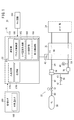
図1は、本発明の一実施形態に係る燃料電池システム10(以下「FCシステム10」ともいう。)のブロック図である。本実施形態のFCシステム10は、車両に用いられるが、その他の用途で用いられてもよい。FCシステム10は、燃料電池スタック20(以下「FCスタック20」又は「FC20」という。)と、アノード系22と、カソード系24と、制御系26と、バッテリ28(図2)とを有する。
A. One Embodiment <A-1. Configuration>
[A-1-1. overall structure]
FIG. 1 is a block diagram of a fuel cell system 10 (hereinafter, also referred to as “
FCスタック20は、例えば、固体高分子電解質膜をアノード電極とカソード電極とで両側から挟み込んで形成された燃料電池セルを積層した構造を有する。アノード系22は、FC20に対して水素ガスを供給する。カソード系24は、FC20に対して酸化ガスを供給する。制御系26は、FC20、アノード系22及びカソード系24を制御する。
The
カソード系24(酸化ガス供給部)の構成は、例えば、特開2012−219276号公報又は特開2014−080634号公報と同様の構成を用いることができる。 As the configuration of the cathode system 24 (oxidizing gas supply unit), for example, the same configuration as that of JP2012-219276A or JP2014-080634 can be used.
[A−1−2.アノード系22]
(A−1−2−1.概要)
図1に示すように、アノード系22(燃料ガス供給部)は、水素タンク30、レギュレータ32、インジェクタ34、パージ弁36、気液分離器38、圧力センサ40及び燃料電池温度センサ42(以下「FC温度センサ42」ともいう。)を有する。水素タンク30は、燃料ガスとしての水素を収容するものであり、配管50、レギュレータ32、配管52、インジェクタ34及び配管54を介して、アノード流路56の入口に接続されている。これにより、水素タンク30の水素は、配管50等を介してアノード流路56に供給可能である。なお、配管50には、遮断弁(図示せず)が設けられており、FCスタック20の発電の際、当該遮断弁は、制御系26の電子制御装置152により開とされる。レギュレータ32は、導入される水素の圧力を所定値に調整して排出する。
[A-1-2. Anode system 22]
(A-1-2-1. Overview)
As shown in FIG. 1, the anode system 22 (fuel gas supply unit) includes a
インジェクタ34は、水素タンク30からの水素をノズルで噴射することで負圧を発生させ、この負圧によって配管58のアノードオフガスを吸引する。
The
アノード流路56の出口は、配管58を介して、インジェクタ34の吸気口に接続されている。そして、アノード流路56から排出されたアノードオフガスは、配管58を通って、配管54に再度導入されることでアノードオフガス(水素)が循環する。なお、アノードオフガスは、アノードにおける電極反応で消費されなかった水素及び水蒸気を含んでいる。
The outlet of the
気液分離器38は、配管58に設けられ、アノードオフガスに含まれる水分{凝縮水(液体)、水蒸気(気体)}を分離・回収する。気液分離器38の詳細については、図2を参照して後述する。
The gas-
配管58の一部は、配管60、パージ弁36及び配管62を介して希釈ボックス(図示しない)に接続されている。パージ弁36は、FCスタック20の発電が安定していないと判定された場合、制御系26からの指令に基づき所定時間、開となる。希釈ボックスは、パージ弁36からのアノードオフガス中の水素を、カソードオフガスで希釈する。
A part of the
圧力センサ40は、アノード系22(ここでは配管58)内の圧力Pを検出して制御系26に送信する。FC温度センサ42(燃料電池スタック相関温度取得部)は、FC20の温度Tfc(以下「FC温度Tfc」又は「スタック温度Tfc」ともいう。)を検出して制御系26に送信する。
The
(A−1−2−2.気液分離器38及びその周辺)
(A−1−2−2−1.概要)
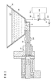
図2は、本実施形態の気液分離器38及びその周辺を簡略的に示す図である。図2では、気液分離器38の下側の貯水領域80に水500が溜まっている。貯水領域80に溜まった水500は、気液分離器38に接続された排水路82を介して外部に排出される。排水路82には、ドレイン弁84が設けられており、制御系26からの指令に基づいて開閉する。図2の矢印300は、ドレイン弁84が開状態のときの水500の流れを示す。気液分離器38の貯水領域80には、PTCヒータ90(PTC:Positive Temperature Coefficient)が設けられている。
(A-1-2-2. Gas-
(A-1-2-2-1. Overview)
FIG. 2 is a diagram simply showing the gas-
(A−1−2−2−2.PTCヒータ90)
PTCヒータ90(以下「ヒータ90」ともいう。)は、サーミスタであり、制御系26からの指令に基づいて水500(凍っている場合を含む。)を加熱する。ヒータ90は、バッテリ28からの電流Ifにより発熱する。図2に示すように、ヒータ90とバッテリ28の間には、オンオフスイッチ100と、可変抵抗器102と、電流センサ104とが配置される。
(A-1-2-2-2. PTC heater 90)
The PTC heater 90 (hereinafter, also referred to as “
オンオフスイッチ100は、制御系26からの指令に応じてオンオフする。可変抵抗器102は、制御系26からの指令に応じて抵抗を変化させる。これにより、ヒータ90に印加させる電圧が切り替えられる。また、電流センサ104は、バッテリ28からヒータ90に供給される電流Ihを検出して制御系26に通知する。
The on / off
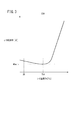
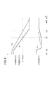
図3は、本実施形態のPTCヒータ90の温度−抵抗特性を示す図である。図3に示すように、ヒータ温度ThがTh1のとき、ヒータ抵抗Rh(以下「抵抗Rh」ともいう。)が最小値Rhminとなる。また、ヒータ温度ThがTh1よりも低くなるほど及び高くなるほどヒータ抵抗Rhは増加する。但し、ヒータ温度ThがTh1よりも低くなるときよりも高くなるときの方がヒータ抵抗Rhの増加度合いは大きい。
FIG. 3 is a diagram showing the temperature-resistance characteristics of the
[A−1−3.制御系26]
(A−1−3−1.制御系26の概要)
図1に示すように、制御系26は、各種センサ150と、電子制御装置152(以下「ECU152」という。)と、タイマ回路154とを有する。
[A-1--3. Control system 26]
(A-1-3-1. Outline of control system 26)
As shown in FIG. 1, the
(A−1−3−2.各種センサ150)
各種センサ150は、ECU152による制御に必要な各種センサ値を検出してECU152に出力する。各種センサ150には、外気温センサ160が含まれる。外気温センサ160は、車両の外気温Tを検出してECU152に出力する。圧力センサ40、FC温度センサ42及び電流センサ104を各種センサ150に含めてもよい。
(A-1--3-2. Various sensors 150)
The
(A−1−3−3.ECU152)
(A−1−3−3−1.ECU152の概要)
ECU152は、FCシステム10全体を制御するコンピュータである。図1に示すように、ECU152は、入出力部170、演算部172及び記憶部174を有する。
(A-1--3-3. ECU152)
(A-1--3-3-1. Outline of ECU 152)
The
(A−1−3−3−2.入出力部170)
入出力部170は、ECU152以外の機器(各種センサ150等)との入出力を行う。入出力部170は、入力されたアナログ信号をデジタル信号に変換する図示しないA/D変換回路を備える。
(A-1--3-2. Input / output unit 170)
The input /
(A−1−3−3−3.演算部172)
演算部172は、例えば、中央処理装置(CPU)を含む。演算部172は、各種センサ150等からの信号に基づいて演算を行う。そして、演算部172は、演算結果に基づき、アノード系22及びカソード系24に対する信号を生成する。
(A-1--3-3-3. Calculation unit 172)
The
図1に示すように、演算部172は、FC出力制御部180と、ヒータ温度算出部182と、ヒータ制御部184と、排水制御部186とを有する。これらの各部は、記憶部174に記憶されているプログラムを実行することにより実現される。前記プログラムは、図示しない通信装置を介して外部機器から供給されてもよい。前記プログラムの一部をハードウェア(回路部品)で構成することもできる。
As shown in FIG. 1, the
FC出力制御部180は、FC20の出力を制御するFC出力制御を実行する。FC出力制御は、車両全体の駆動力を制御する、図示しない統合制御電子制御装置(以下「統合制御ECU」ともいう。)からの指令に基づいて行われる。
The FC
ヒータ温度算出部182(加熱手段温度推定部)は、PTCヒータ90の温度Thを算出又は推定するヒータ温度算出制御を実行する。ヒータ制御部184は、PTCヒータ90のオンオフ等を制御するヒータ制御を実行する。排水制御部186は、気液分離器38内の水500の排出を制御する気液分離器排水制御を実行する。
The heater temperature calculation unit 182 (heating means temperature estimation unit) executes heater temperature calculation control for calculating or estimating the temperature Th of the
(A−1−3−3−4.記憶部174)
記憶部174は、演算部172が利用するプログラム及びデータを記憶する。記憶部174は、例えば、ランダム・アクセス・メモリ(以下「RAM」という。)を備える。RAMとしては、レジスタ等の揮発性メモリと、フラッシュメモリ等の不揮発性メモリとを用いることができる。また、記憶部174は、RAMに加え、リード・オンリー・メモリ(ROM)及び/又はソリッド・ステート・ドライブ(SSD)を有してもよい。
(A-1--3-4. Storage unit 174)
The
(A−1−3−4.タイマ回路154)
タイマ回路154は、ECU152がオンになるタイミングを設定し、当該タイミングが来たときにECU152をオンにする。
(A-1--3-4. Timer circuit 154)
The
<A−2.本実施形態の気液分離器排水制御>
[A−2−1.概要]
上記のように、本実施形態のECU152は、気液分離器排水制御を実行する。気液分離器排水制御では、気液分離器38内に水500が所定量以上溜まった場合、ドレイン弁84を開いて水500を外部に排水する。但し、ここでの所定量は、直接的に水500の量を量るのではなく、ヒータ抵抗Rhを用いる。
<A-2. Gas-liquid separator drainage control of this embodiment>
[A-2-1. Overview]
As described above, the
以下に述べるように、気液分離器排水制御では、大きく分けて、FCシステム起動時制御と、FCシステム作動時制御と、FCシステム停止時制御とを含む。FCシステム起動時制御(以下「起動時制御」ともいう。)は、FCシステム10の起動時(又は発電開始時)において、PTCヒータ90により気液分離器38内を暖機する制御である。起動時制御自体では排水を行わず、後に続くFCシステム作動時制御で排水を行う点に留意されたい。
As described below, the gas-liquid separator drainage control is broadly divided into FC system start-up control, FC system operation time control, and FC system stop time control. The FC system start-up control (hereinafter, also referred to as “start-up control”) is a control that warms the inside of the gas-
FCシステム作動時制御(以下「作動時制御」ともいう。)は、FCシステム10の作動時(又は発電中)において、気液分離器38内の水500を排出する制御であり、起動時制御に続いて行われる。
The FC system operating control (hereinafter, also referred to as “operating control”) is a control for discharging the
FCシステム停止時制御(以下「停止時制御」ともいう。)は、FCシステム10の停止時(又は発電停止時)において、気液分離器38内の水500を排出する制御であり、作動時制御に続いて行われる。また、1度の停止時制御が行われた後、起動時制御が所定期間行われなかった場合、停止時制御が繰り返される。
The control when the FC system is stopped (hereinafter, also referred to as “control when stopped”) is a control for discharging the
[A−2−2.気液分離器排水制御の全体的な流れ]
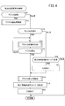
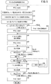
図4は、本実施形態の気液分離器排水制御の概要を示すフローチャートである。ステップS11において、ECU152は、FCシステム10が起動したか否かを判定する。当該判定は、例えば、FC出力制御部180からの通知により行う。FCシステム10が起動した場合(S11:TRUE)、ステップS12に進む。ステップS12において、ECU152は、起動時制御を実行する。起動時制御については、図7及び図8を参照して後述する。ステップS12の後、ステップS14に進む。
[A-2-2. Overall flow of gas-liquid separator drainage control]
FIG. 4 is a flowchart showing an outline of the gas-liquid separator drainage control of the present embodiment. In step S11, the
FCシステム10が起動していない場合(S11:FALSE)、ステップS13に進む。ステップS13において、ECU152は、FCシステム10が作動中であるか否かを判定する。当該判定は、例えば、FC出力制御部180からの通知により行う。FCシステム10が作動中である場合(S13:TRUE)、ステップS14に進む。ステップS14において、ECU152は、作動時制御を実行する。作動時制御については、図5及び図6を参照して後述する。
If the
ステップS15において、ECU152は、FCシステム10が停止したか否かを判定する。当該判定は、例えば、FC出力制御部180からの通知により行う。FCシステム10が停止した場合(S15:TRUE)、ステップS18に進む。FCシステム10が停止していない場合(S15:FALSE)、ステップS14に戻る。
In step S15, the
ステップS13においてFCシステム10が作動中でない場合(S13:FALSE)、FCシステム10は停止中である。その場合、ステップS16において、ECU152は、停止時制御の実行タイミングが到来したか否かを判定する。当該判定は、例えば、タイマ回路154が監視することにより行う。停止時制御の実行タイミングが到来した場合(S16:TRUE)、ステップS17に進む。停止時制御の実行タイミングが到来していない場合(S16:FALSE)、今回の気液分離器排水制御を終了し、所定時間の経過後にステップS11に戻る。
If the
ステップS17において、ECU152は、タイマ回路154によりオンする。ステップS18において、ECU152は、停止時制御を実行する。停止時制御については、図10を参照して後述する。ステップS19において、ECU152は、タイマ回路154における停止時制御の実行タイミングを設定又は更新する。ステップS20において、ECU152は、オフ(又はスリープモード)となる。そして、今回の気液分離器排水制御を終了し、所定時間の経過後にステップS11に戻る。
In step S17, the
[A−2−3.FCシステム作動時制御]
理解の容易化のため、以下では、起動時制御(図4のS12)よりも先に作動時制御(S14)について説明する。上記のように、作動時制御は、FCシステム10の作動時(又は発電中)において、気液分離器38内の水500を排出する制御であり、起動時制御に続いて行われる。
[A-2-3. FC system operation control]
For ease of understanding, the operation time control (S14) will be described below before the start-up time control (S12 in FIG. 4). As described above, the operation-time control is a control for discharging the
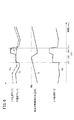
図5は、本実施形態のFCシステム作動時制御のフローチャート(図4のS14の詳細)である。図6は、本実施形態のFCシステム作動時制御を実行する際の各種数値の一例を示すタイムチャートである。図6では、ヒータ温度Th、FC温度Tfc、気液分離器38内の水量Q[L]及びヒータ抵抗Rhが示されている。
FIG. 5 is a flowchart of the FC system operating control of the present embodiment (details of S14 in FIG. 4). FIG. 6 is a time chart showing an example of various numerical values when the FC system operating control of the present embodiment is executed. In FIG. 6, the heater temperature Th, the FC temperature Tfc, the amount of water Q [L] in the gas-
図5のステップS21〜S25では、気液分離器38内に水500が溜まっているか否かを判定する。すなわち、ステップS21において、ECU152は、PTCヒータ90をオンする(図6の時点t11)。ステップS22において、ECU152は、FC温度センサ42からのFC温度Tfcと、電流センサ104からのヒータ電流Ihと、ヒータ90に印加されているヒータ電圧Vhとを取得する。ヒータ電圧Vhは、バッテリ28の出力電圧と、ECU152が設定している可変抵抗器102の抵抗とに基づいて算出する。
In steps S21 to S25 of FIG. 5, it is determined whether or not
ステップS23において、ECU152は、ヒータ電流Ihとヒータ90への印加電圧Vhに基づいてヒータ抵抗Rhを算出する(Rh=Vh/Ih)。
In step S23, the
ステップS24において、ECU152は、ヒータ抵抗Rhに基づいてヒータ温度Thを算出する。すなわち、ヒータ抵抗Rhとヒータ温度Thの関係を規定したマップ200(Th−Rhマップ200。図3)を記憶部174に予め記憶しておく。そして、ECU152は、ヒータ抵抗Rhに対応するヒータ温度ThをTh−Rhマップ200から読み出して用いる。
In step S24, the
なお、図3に示したように、PTCヒータ90は、抵抗Rhの最小値Rhminを有し、その前後が最小値Rhminよりも大きくなる。そのようなヒータ90の場合、図示しない冷媒の温度又は水素ガスの温度を考慮して、抵抗Rhが最小値Rhminよりも大きいか又は小さいかを判定する。
As shown in FIG. 3, the
図5に戻り、ステップS25において、ECU152は、ヒータ温度ThとFC温度Tfcの差ΔT(以下「温度差ΔT」ともいう。)が第1温度差閾値THΔT1以下であるか否かを判定する。第1温度差閾値THΔT1は、PTCヒータ90の一部又は全部が水500に浸かっているか否かを判定する閾値である。すなわち、PTCヒータ90の一部又は全部が水500に浸かっている場合、温度差ΔTは比較的小さくなり、PTCヒータ90が水500に浸かっていない場合、温度差ΔTは比較的大きくなる。これらの状態を区別するために第1温度差閾値THΔT1が用いられる。
Returning to FIG. 5, in step S25, the
温度差ΔTが第1温度差閾値THΔT1以下でない場合(S25:FALSE)、PTCヒータ90は水500に浸かっていない。換言すると、水500の水量Qは水量閾値THq以下である。そこで、ステップS26において、ECU152は、PTCヒータ90を所定時間オフにし、その後、ステップS21に戻る。温度差ΔTが第1温度差閾値THΔT1以下である場合(S25:TRUE)、PTCヒータ90の一部又は全部が水500に浸かっている。その場合、ステップS27において、ECU152は、PTCヒータ90をオフにする。
When the temperature difference ΔT is not equal to or less than the first temperature difference threshold THΔT1 (S25: FALSE), the
図5のステップS28〜S34では、気液分離器38内の水500を外部に排出する。このうち、ステップS28〜S31は、気液分離器38内に残水がないとの判定を仮に行うものである。車両の傾きによっては、ステップS28〜S31の判定では、残水がないとの誤判定を行う可能性がある。そこで、ステップS32〜S37では、ステップS28〜S31から時間を置いて、再度、気液分離器38内に残水がないことを確認する。
In steps S28 to S34 of FIG. 5, the
図5のステップS28において、ECU152は、ドレイン弁84を開く(図6の時点t12)。これにより、気液分離器38内の水500がドレイン弁84を介して外部に排出され始める。ステップS29において、ECU152は、PTCヒータ90をオンにする。なお、図5のステップS27とステップS29の間の時間が短い場合、ステップS27、S29の両方を省略してもよい。
In step S28 of FIG. 5, the
ステップS30において、ECU152は、ステップS22、S23と同様の方法でヒータ抵抗Rhを取得又は算出する。ステップS31において、ECU152は、ヒータ抵抗Rhが第1抵抗閾値THrh1以上であるか否かを判定する。第1抵抗閾値THrh1は、PTCヒータ90の一部又は全部が水500の中に浸かっている場合には取り得ないほどの温度として設定される。ヒータ抵抗Rhが第1抵抗閾値THrh1以上でない場合(S31:FALSE)、PTCヒータ90の加熱は不十分であり、PTCヒータ90の一部又は全部が水500の中に浸かっている可能性がある。その場合、ステップS30に戻る。ヒータ抵抗Rhが第1抵抗閾値THrh1以上である場合(S31:TRUE)、PTCヒータ90が十分に加熱され、PTCヒータ90は、水500の中に浸かっていないと考えられる(図6の時点t13)。その場合、ステップS32に進む。
In step S30, the
ステップS32において、ECU152は、カウント値CNTをリセットする。ステップS33において、ECU152は、カウント値CNTが第1カウント閾値THcnt1以上であるか否かを判定する。第1カウント閾値THcnt1は、ステップS31の時点において車両が傾斜していた場合でも、その後に傾斜がなくなるまでの時間を十分に確保するように設定される。カウント値CNTが第1カウント閾値THcnt1以上でない場合(S33:FALSE)、ステップS34において、ECU152は、カウント値CNTを1増加させてステップS33に戻る。カウント値CNTが第1カウント閾値THcnt1以上である場合(S33:TRUE)、ステップS35に進む。
In step S32, the
ステップS35において、ECU152は、ドレイン弁84を閉じる(図6の時点t14)。ステップS36において、ECU152は、ステップS30と同様にヒータ抵抗Rhを取得する。ステップS37において、ECU152は、ヒータ抵抗Rhが第1抵抗閾値THrh1以上であるか否かを判定する。ステップS37は、ステップS31と同様に行われるが、互いに異なる第1抵抗閾値THrh1を用いてもよい。
In step S35, the
ヒータ抵抗Rhが第1抵抗閾値THrh1以上でない場合(S37:FALSE)、PTCヒータ90の一部又は全部が水500の中に浸かっている可能性がある。すなわち、ステップS31の時点では、車両が傾いていたため、PTCヒータ90が水500に浸かっていなかったが、その後、車両の傾きが変化したため、PTCヒータ90の一部又は全部が水500に浸かっていると考えられる。その場合、ステップS28に戻る。ヒータ抵抗Rhが第1抵抗閾値THrh1以上である場合(S37:TRUE)、PTCヒータ90は、水500の中に浸かっていないとの判定を確定し、ステップS38に進む。ステップS38において、ECU152は、PTCヒータ90をオフにして今回の作動時制御を終了する(図6の時点t15)。
If the heater resistance Rh is not equal to or higher than the first resistance threshold THrh1 (S37: FALSE), it is possible that part or all of the
[A−2−4.FCシステム起動時制御]
上記のように、FCシステム起動時制御(図4のS12)は、FCシステム10の起動時(又は発電開始時)において、PTCヒータ90により気液分離器38内を暖機する制御である。起動時制御自体では排水を行わず、後に続くFCシステム作動時制御で排水を行う点に留意されたい。
[A-2-4. FC system startup control]
As described above, the control at the time of starting the FC system (S12 in FIG. 4) is a control for warming the inside of the gas-
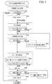
図7は、本実施形態のFCシステム起動時制御のフローチャート(図4のS12の詳細)である。図8は、本実施形態のFCシステム起動時制御を実行する際の各種数値の一例を示すタイムチャートである。図8では、ヒータ抵抗Rh、ヒータ温度Th及びFC温度Tfcが示されている。 FIG. 7 is a flowchart of the FC system startup control of the present embodiment (details of S12 in FIG. 4). FIG. 8 is a time chart showing an example of various numerical values when the FC system startup control of the present embodiment is executed. In FIG. 8, the heater resistance Rh, the heater temperature Th, and the FC temperature Tfc are shown.
図7のステップS51、S52では、PTCヒータ90による加熱の必要性を判定する。すなわち、ステップS51において、ECU152は、FC温度センサ42からFC温度Tfcを取得する。ステップS52において、ECU152は、FC温度Tfcが第1温度閾値THtfc1以下であるか否かを判定する。第1温度閾値THtfc1は、FC20が極低温状態にあるか否かを判定する閾値であり、例えば、−10〜−40℃の範囲で設定される。FC温度Tfcが第1温度閾値THtfc1以下でない場合(S52:FALSE)、今回の起動時制御を終了する。FC温度Tfcが第1温度閾値THtfc1以下である場合(S52:TRUE)、ステップS53に進む。
In steps S51 and S52 of FIG. 7, the necessity of heating by the
ステップS53において、ECU152は、PTCヒータ90をオンする(図8の時点t21)。これにより、ヒータ抵抗RhはRh1まで増加し、ヒータ温度ThはTh1まで増加する(図8の時点t22)。PTCヒータ90のオンに伴い、ECU152は、FC20の発電を開始する。
In step S53, the
ステップS54、S55において、気液分離器38内に氷がある場合、PTCヒータ90又はFC20の作動により氷が解けて、PTCヒータ90の周辺に水500が溜まっている状態であるか否かを判定する。すなわち、ステップS54において、ECU152は、FC温度Tfcを取得又は更新する。ステップS55において、ECU152は、FC温度Tfcが第2温度閾値THtfc2以上であるか否かを判定する。FC温度Tfcが第2温度閾値THtfc2以上でない場合(S55:FALSE)、ステップS54に戻る。FC温度Tfcが第2温度閾値THtfc2以上である場合(S55:TRUE)、ステップS56に進む(図8の時点t23)。
In steps S54 and S55, if there is ice in the gas-
ステップS54、S55の代わりに、例えば、PTCヒータ90のオン開始からの時間を用いてもよい。或いは、ヒータ抵抗Rhの変化をステップS54、S55の代わりに用いることも可能である。
Instead of steps S54 and S55, for example, the time from the start of turning on the
ステップS56において、ECU152は、図5のステップS22、S23と同様の方法により、ヒータ抵抗Rhを取得する。ステップS57において、ECU152は、ヒータ抵抗Rhが第2抵抗閾値THrh2以上であるか否かを判定する。第2抵抗閾値THrh2は、PTCヒータ90が十分に加熱されているか否かを判定する閾値である。ヒータ抵抗Rhが第2抵抗閾値THrh2以上でない場合(S57:FALSE)、ステップS58において、ECU152は、可変抵抗器102(図2)を制御してPTCヒータ90への印加電圧Vhを増加させ、ステップS56に戻る。図8の時点t24〜t25における破線で示すヒータ温度Thが、印加電圧Vhの増加を行う場合の値であり、時点t24〜t25における実線で示すヒータ温度Thが、印加電圧Vhの増加を行わない場合の値である。
In step S56, the
ヒータ抵抗Rhが第2抵抗閾値THrh2以上である場合(S57:TRUE)、ステップS59に進む。ステップS59において、ECU152は、FC温度Tfcとヒータ抵抗Rhを取得する。ステップS60において、ECU152は、ヒータ抵抗Rhに基づいてヒータ温度Thを算出する。ステップS60は、図5のステップS24と同様に行う。
When the heater resistance Rh is equal to or higher than the second resistance threshold value THrh2 (S57: TRUE), the process proceeds to step S59. In step S59, the
ステップS61において、ECU152は、ヒータ温度ThとFC温度Tfcの温度差ΔTが第2温度差閾値THΔT2以上であるか否かを判定する。第2温度差閾値THΔT2は、PTCヒータ90の一部又は全部が水500に浸かっているか否かを判定する閾値である。すなわち、PTCヒータ90の一部又は全部が水500に浸かっている場合、温度差ΔTは比較的小さくなり、PTCヒータ90が水500に浸かっていない場合、温度差ΔTは比較的大きくなる。これらの状態を区別するために第2温度差閾値THΔT2が用いられる。
In step S61, the
温度差ΔTが第2温度差閾値THΔT2以上でない場合(S61:FALSE)、PTCヒータ90の一部又は全部が水500に浸かっている。そこで、PTCヒータ90の作動を継続し、ステップS59に戻る。温度差ΔTが第2温度差閾値THΔT2以上である場合(S61:TRUE)、PTCヒータ90は、水500に浸かっていない。そこで、ステップS62に進む。
When the temperature difference ΔT is not equal to or greater than the second temperature difference threshold THΔT2 (S61: FALSE), a part or all of the
ステップS62において、ECU152は、カウント値CNTをリセットする。ステップS63において、ECU152は、カウント値CNTが第2カウント閾値THcnt2以上であるか否かを判定する。第2カウント閾値THcnt2は、気液分離器38内の生成水が十分暖められることを確保する時間である。カウント値CNTが第2カウント閾値THcnt2以上でない場合(S63:FALSE)、ステップS64において、ECU152は、カウント値CNTを1増加させてステップS63に戻る。カウント値CNTが第2カウント閾値THcnt2以上である場合(S63:TRUE)、ステップS65に進む。
In step S62, the
ステップS65において、ECU152は、PTCヒータ90をオフする(図8の時点t26)。
In step S65, the
[A−2−5.FCシステム停止時制御]
上記のように、FCシステム停止時制御は、FCシステム10の停止時(又は発電停止時)において、気液分離器38内の水500を排出する制御であり、作動時制御に続いて行われる。また、1度の停止時制御が行われた後、起動時制御が所定期間行われなかった場合、停止時制御が繰り返される。
[A-2-5. Control when FC system is stopped]
As described above, the control when the FC system is stopped is a control for discharging the
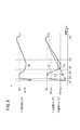
図9は、本実施形態のFCシステム停止時制御を実行しない場合の各種数値の一例を示すタイムチャートである。図9では、ヒータ温度Th、FC温度Tfc及びヒータ抵抗Rhが示されている。 FIG. 9 is a time chart showing an example of various numerical values when the FC system stop control of the present embodiment is not executed. In FIG. 9, the heater temperature Th, the FC temperature Tfc, and the heater resistance Rh are shown.
図9の時点t31〜t32の間は、FCシステム10が発電中である。その際、ヒータ90はオフであったため、ヒータ温度Thは、FC20の周辺補機と同様の温度となる。すなわち、FC20の発熱等により、ヒータ温度Thは、外気温よりも高い値となる。
During the time points t31 to t32 in FIG. 9, the
時点t32において、FCシステム10が停止した。これにより、FC20による発熱が停止する。加えて、日没等に伴って外気温が低下していく。そのため、時点t32からFC温度Tfc及びヒータ温度Thが低下していく。
At time t32, the
FCシステム10の発電中(t31〜t32)は、FC温度Tfcとヒータ温度Thは、比較的近い値で推移する。FCシステム10の停止後、熱マスの大きいFC20の温度低下は緩やかであるのに対し、ヒータ90及びその他の周辺補機の温度低下は比較的急である。
During power generation (t31 to t32) of the
そのため、FC温度Tfcよりも先にヒータ温度Thが0℃に到達し(時点t33)、その他の周辺補機が凍結し始める。その後の時点t34においてFC温度Tfcが0℃に到達する。従って、FC温度Tfcに基づいてその他の周辺補機の温度を監視しようとすると誤差が大きくなり、その他の周辺補機の凍結を十分に判定することが困難となる。 Therefore, the heater temperature Th reaches 0 ° C. (time point t33) before the FC temperature Tfc, and other peripheral auxiliary machines start to freeze. At the subsequent time point t34, the FC temperature Tfc reaches 0 ° C. Therefore, if an attempt is made to monitor the temperature of the other peripheral auxiliary equipment based on the FC temperature Tfc, the error becomes large, and it becomes difficult to sufficiently determine the freezing of the other peripheral auxiliary equipment.
そこで、本実施形態では、FC温度Tfcではなく、ヒータ温度Thを用いて、その他の周辺補機の温度を監視する。 Therefore, in the present embodiment, the heater temperature Th is used instead of the FC temperature Tfc to monitor the temperatures of other peripheral auxiliary machines.
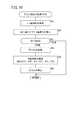
図10は、本実施形態のFCシステム停止時制御のフローチャート(図4のS18の詳細)である。停止時制御は、例えば図9の時点t32から開始される。図10のステップS81において、ECU152は、図5のステップS22、S23と同様の方法で、ヒータ抵抗Rhを取得する。ステップS82において、ECU152は、ヒータ抵抗Rhに基づいてヒータ温度Thを算出する。
FIG. 10 is a flowchart of the control when the FC system is stopped according to the present embodiment (details of S18 in FIG. 4). Stop control starts, for example, at time t32 in FIG. In step S81 of FIG. 10, the
ステップS83において、ECU152は、ヒータ温度Thが第3温度閾値THth3以下であるか否かを判定する。第3温度閾値THth3は、水500が凍結し始めることを判定する閾値であり、例えば−1〜3℃の範囲の固定値として設定され、図9では0℃に設定されている。ヒータ温度Thが第3温度閾値THth3以下でない場合(S83:FALSE)、今回の停止時制御を終了する。ヒータ温度Thが第3温度閾値THth3以下である場合(S83:TRUE)、ステップS84に進む。
In step S83, the
ステップS84において、ECU152は、FCシステム10を起動する(図9の時点t33)。FCシステム10の起動に伴って、PTCヒータ90をオンにするため、図9のような例では、時点t33においてヒータ温度Thが上昇することになる(図9では、ヒータ温度Thの上昇は示していない。)。
In step S84, the
ステップS85において、ECU152は、停止時排水制御を実行する。停止時排水制御は、図5のステップS21〜S25、S27〜S31、S35、S38を行う。ステップS86において、ECU152は、FCシステム10を停止して、今回の停止時制御を終了する。
In step S85, the
<A−3.本実施形態の効果>
以上のように、本実施形態によれば、FC温度Tfc(燃料電池スタックの相関温度)とヒータ温度Th(加熱手段の温度)とに基づいて気液分離器38内の水500の有無を判定する(図5のS25)。そのため、水位レベルセンサ等の追加部品を必要とせず、簡易なシステムで気液分離器38内の水500の存在を把握することが可能となる。或いは、水位レベルセンサ等の追加部品を設ける場合でも、本実施形態を適用することで、フェールセーフの点で優れることが可能となる。よって、FCシステム10内の水500を好適に検出又は排出することが可能となる。
<A-3. Effect of this embodiment>
As described above, according to the present embodiment, the presence or absence of
本実施形態において、ECU152(制御部)は、低温始動時(図7のS52:TRUE)にPTCヒータ90(加熱手段)を用いて加熱制御する(S53)と共に、水500の有無に関する判断結果に基づいてヒータ90の加熱量を制御する(S56〜S58)。これにより、低温始動時の加熱制御を適切に行うことで、水500の凍結による閉塞を抑制することが可能となる。
In the present embodiment, the ECU 152 (control unit) controls the heating using the PTC heater 90 (heating means) at the time of low temperature start (S52: TRUE in FIG. 7) (S53), and determines the presence or absence of
本実施形態において、気液分離器38は貯水領域80に溜まった水500を排水するドレイン弁84を備える(図2)。また、ECU152(制御部)は、水500の有無に関する判断結果に基づいてドレイン弁84を駆動させる(図5のS28)ことにより排水制御を行う。これにより、簡易な構成で気液分離器38内の排水制御を行うことが可能となる。
In the present embodiment, the gas-
本実施形態において、ECU152(制御部)は、排水制御を実施している間のPTCヒータ90(加熱手段)の抵抗Rhに基づいて、排水が正常に行われたか否かを判断する(図5のS30、S31)。ヒータ抵抗Rhを見ることにより、排水が完了したか否かを判断するため、簡易且つ低コストの構成で排水制御を実現することが可能となる。 In the present embodiment, the ECU 152 (control unit) determines whether or not drainage is normally performed based on the resistance Rh of the PTC heater 90 (heating means) while performing drainage control (FIG. 5). S30, S31). Since it is determined whether or not the drainage is completed by looking at the heater resistance Rh, it is possible to realize the drainage control with a simple and low-cost configuration.
本実施形態において、ECU152(制御部)は、ヒータ抵抗Rh(加熱手段の抵抗)が第1抵抗閾値THrh1以上になったこと(図5のS31:TRUE)により排水が正常に行われたと判断する。これにより、簡易に排水の正常終了を判定することが可能となる。 In the present embodiment, the ECU 152 (control unit) determines that the drainage is normally performed because the heater resistance Rh (resistance of the heating means) becomes equal to or higher than the first resistance threshold value THrh1 (S31: TRUE in FIG. 5). .. This makes it possible to easily determine the normal end of drainage.
本実施形態において、ECU152(制御部)は、排水が正常に行われたと判断した(図5のS31:TRUE)後に、ヒータ抵抗Rhが第1抵抗閾値THrh1未満になったこと(S37:FALSE)により気液分離器38内に水500が残水していたと判断し、排水制御を再度行う(S28〜S35)。
In the present embodiment, the ECU 152 (control unit) determines that the drainage has been performed normally (S31: TRUE in FIG. 5), and then the heater resistance Rh becomes less than the first resistance threshold THrh1 (S37: FALSE). Therefore, it is determined that the
FCシステム10(又はこれが設けられた車両(移動体))の傾斜により、排水が正常に行われていないにも関わらず排水が完了したと判断する可能性がある。本実施形態では、FCシステム10の傾斜状態が解消され、残水が確認された際には、排水制御が再び行われるので、凍結による閉塞を確実に抑制することが可能となる。
Due to the inclination of the FC system 10 (or the vehicle (moving body) provided with the FC system 10), it may be determined that the drainage is completed even though the drainage is not performed normally. In the present embodiment, when the inclined state of the
B.変形例
なお、本発明は、上記実施形態に限らず、本明細書の記載内容に基づき、種々の構成を採り得ることはもちろんである。例えば、以下の構成を採用することができる。
B. Modifications The present invention is not limited to the above-described embodiment, and it goes without saying that various configurations can be adopted based on the contents described in the present specification. For example, the following configuration can be adopted.
<B−1.適用対象>
上記実施形態では、FCシステム10が生成した電力を、燃料電池車両(FCV)に供給することを想定していた。しかしながら、例えば、FC温度Tfcとヒータ温度Thとに基づいて気液分離器38内の水500の有無を判定する観点からすれば、これに限らない。例えば、FCシステム10が生成した電力は、住宅等に供給してもよい。
<B-1. Applicable target>
In the above embodiment, it is assumed that the electric power generated by the
<B−2.気液分離器38>
上記実施形態では、気液分離器38をアノード系22に設けた(図1)。しかしながら、例えば、FC温度Tfcとヒータ温度Thとに基づいて気液分離器38内の水500の有無を判定する観点からすれば、これに限らない。例えば、気液分離器38は、アノード系22に加えて又はこれに代えて、カソード系24に設けてもよい。
<B-2. Gas-
In the above embodiment, the gas-
<B−3.ECU152の制御>
[B−3−1.気液分離器排水制御全般]
上記実施形態の気液分離器排水制御では、図7に示す起動時制御と、図5に示す作動時制御と、図10に示す停止時制御を組み合わせた。しかしながら、例えば、FC温度Tfcとヒータ温度Thとに基づいて気液分離器38内の水500の有無を判定する観点からすれば、これに限らない。例えば、図7に示す以外の方法で起動時制御を行うことも可能である。或いは、図5に示す方法以外で作動時制御を行うことも可能である。或いは、図10に示す以外の方法で停止時制御を行うことも可能である。
<B-3. Control of
[B-3-1. Gas-liquid separator drainage control in general]
In the gas-liquid separator drainage control of the above embodiment, the start-up control shown in FIG. 7, the operation-time control shown in FIG. 5, and the stop-time control shown in FIG. 10 are combined. However, the present invention is not limited to this, for example, from the viewpoint of determining the presence or absence of
[B−3−2.起動時制御]
上記実施形態の起動時制御では、可変抵抗器102(図2)を用いてPTCヒータ90への印加電圧Vhを変化させた(図7のS56〜S58)。しかしながら、例えば、ヒータ90への印加電圧Vhを変化させる観点からすれば、これに限らない。例えば、コンバータを用いてPTCヒータ90への印加電圧Vhを変化させてもよい。
[B-3-2. Start-up control]
In the start-up control of the above embodiment, the variable resistor 102 (FIG. 2) was used to change the voltage Vh applied to the PTC heater 90 (S56 to S58 in FIG. 7). However, it is not limited to this, for example, from the viewpoint of changing the voltage Vh applied to the
上記実施形態の起動時制御では、ヒータ抵抗Rhに基づいてPTCヒータ90への印加電圧Vhを変化させた(図7のS56〜S58)。しかしながら、例えば、FC温度Tfcとヒータ温度Thとに基づいて気液分離器38内の水500の有無を判定する観点からすれば、これに限らない。例えば、PTCヒータ90への印加電圧Vhは一定としてもよい。
In the start-up control of the above embodiment, the voltage Vh applied to the
[B−3−3.作動時制御]
上記実施形態では、FC温度Tfcとヒータ温度Thとに基づいて気液分離器38内の水500の有無を判定した(図5のS25)。しかしながら、例えば、FCスタック20の温度に相関する燃料電池スタックの相関温度と、気液分離器38の貯水領域80の底部に配置される加熱手段の温度に相関する加熱手段温度とに基づいて気液分離器38内の水500の有無を判定する観点からすれば、これに限らない。FC温度Tfc(スタック温度Tfc)の代わりに、例えば、FC20を冷却する冷媒の温度を燃料電池スタック相関温度として用いることも可能である。
[B-3-3. Control during operation]
In the above embodiment, the presence or absence of
上記実施形態において、ECU152(制御部)は、排水制御を実施している間のPTCヒータ90(加熱手段)の抵抗Rhに基づいて、排水が正常に行われたか否かを判断した(図5のS30、S31)。しかしながら、気液分離器38の排水が完了したか否かを判定する観点からすれば、これに限らない。例えば、ECU152(制御部)は、排水制御を実施している間のPTCヒータ90(加熱手段)の温度変化に基づいて、排水が正常に行われたか否かを判断してもよい。ヒータ90の温度変化を見ることにより、排水が完了したか否かを判断するため、簡易且つ低コストの構成で排水制御を実現することが可能となる。
In the above embodiment, the ECU 152 (control unit) determines whether or not the drainage is normally performed based on the resistance Rh of the PTC heater 90 (heating means) while the drainage control is being performed (FIG. 5). S30, S31). However, it is not limited to this from the viewpoint of determining whether or not the drainage of the gas-
上記実施形態において、ECU152(制御部)は、ヒータ抵抗Rh(加熱手段の抵抗)が第1抵抗閾値THrh1以上になったこと(図5のS31:TRUE)により排水が正常に行われたと判断した。しかしながら、例えば、気液分離器38の排水が完了したか否かを判定する観点からすれば、これに限らない。
In the above embodiment, the ECU 152 (control unit) determines that the drainage is normally performed because the heater resistance Rh (resistance of the heating means) becomes equal to or higher than the first resistance threshold value THrh1 (S31: TRUE in FIG. 5). .. However, it is not limited to this, for example, from the viewpoint of determining whether or not the drainage of the gas-
例えば、ECU152(制御部)は、FC温度Tfcとヒータ温度Thとの差ΔTに基づいて、換言すると、FC温度Tfcに対して、ヒータ温度Thが所定値以上変化したことにより排水が正常に行われたと判断してもよい。熱マスの大きいFCスタック20のFC温度Tfcを基準として、ヒータ温度Thにより排水が行われたか否かを判断するため、システム稼働状況に応じた適切な排水判断を行うことが可能となる。
For example, the ECU 152 (control unit) drains water normally because the heater temperature Th changes by a predetermined value or more with respect to the FC temperature Tfc based on the difference ΔT between the FC temperature Tfc and the heater temperature Th. You may judge that it was broken. Since it is determined whether or not the drainage is performed by the heater temperature Th based on the FC temperature Tfc of the
上記実施形態において、ECU152(制御部)は、排水が正常に行われたと判断した(図5のS31:TRUE)後に、ヒータ抵抗Rhが第1抵抗閾値THrh1未満になったこと(S37:FALSE)により気液分離器38内に水500が残水していたと判断し、排水制御を再度行った(S28〜S35)。しかしながら、例えば、FC温度Tfcとヒータ温度Thとに基づいて気液分離器38内の水500の有無を判定する観点からすれば、これに限らない。例えば、図5のステップS32〜S34は省略することも可能である。
In the above embodiment, the ECU 152 (control unit) determines that the drainage has been performed normally (S31: TRUE in FIG. 5), and then the heater resistance Rh becomes less than the first resistance threshold THhr1 (S37: FALSE). Therefore, it was determined that the
[B−3−4.停止時制御]
上記実施形態の停止時制御では、停止時排水制御(図10のS85)の内容を、図5のステップS21〜S25、S27〜S31、S35、S38と同様とした。しかしながら、例えば、気液分離器38内の水500を排出する観点からすれば、これに限らない。
[B-3-4. Control when stopped]
In the stop control of the above embodiment, the contents of the stop drainage control (S85 in FIG. 10) are the same as in steps S21 to S25, S27 to S31, S35, and S38 in FIG. However, it is not limited to this, for example, from the viewpoint of discharging the
[B−3−5.その他]
上記実施形態では、数値の比較において等号を含む場合と含まない場合とが存在した。しかしながら、例えば、等号を含む又は等号を外す特別な意味がなければ(換言すると、本発明の効果を得られる場合)、数値の比較において等号を含ませるか或いは含ませないかは任意に設定可能である。
[B-3-5. Others]
In the above embodiment, there are cases where the equal sign is included and cases where the equal sign is not included in the comparison of numerical values. However, for example, unless there is a special meaning to include or remove the equal sign (in other words, when the effect of the present invention can be obtained), it is optional to include or not include the equal sign in the numerical comparison. Can be set to.
その意味において、例えば、図5のステップS25における温度差ΔTが第1温度差閾値THΔT1以下であるか否かの判定を、温度差ΔTが第1温度差閾値THΔT1未満であるか否かの判定に置き換えることができる。 In that sense, for example, it is determined whether or not the temperature difference ΔT in step S25 of FIG. 5 is equal to or less than the first temperature difference threshold value THΔT1, and whether or not the temperature difference ΔT is less than or equal to the first temperature difference threshold value THΔT1. Can be replaced with.
上記実施形態では、図4、図5、図7及び図10に示すフローを用いた。しかしながら、例えば、本発明の効果を得られる場合、フローの内容(各ステップの順番)は、これに限らない。例えば図5のステップS35とステップS36の順番を入れ替えることが可能である。 In the above embodiment, the flows shown in FIGS. 4, 5, 7, and 10 are used. However, for example, when the effect of the present invention can be obtained, the content of the flow (order of each step) is not limited to this. For example, the order of step S35 and step S36 in FIG. 5 can be exchanged.
20…燃料電池スタック 22…アノード系(燃料ガス供給部)
24…カソード系(酸化ガス供給部) 38…気液分離器
42…FC温度センサ(燃料電池スタック相関温度取得部)
80…貯水領域 84…ドレイン弁
90…PTCヒータ(加熱手段)
182…ヒータ温度算出部(加熱手段温度推定部)
186…排水制御部(制御部) 500…水
Tfc…FC温度(燃料電池スタック相関温度)
Th…ヒータ温度(加熱手段の温度)
20 ...
24 ... Cathode system (oxidation gas supply unit) 38 ... Gas-
80 ...
182 ... Heater temperature calculation unit (heating means temperature estimation unit)
186 ... Drainage control unit (control unit) 500 ... Water Tfc ... FC temperature (fuel cell stack correlation temperature)
Th ... Heater temperature (temperature of heating means)
Claims (7)
前記燃料電池スタックへ燃料ガスを供給する燃料ガス供給部と、
前記燃料電池スタックへ酸化ガスを供給する酸化ガス供給部と、
前記燃料ガス供給部及び前記酸化ガス供給部の少なくとも一方に設置される気液分離器と、
前記燃料電池スタックの温度に相関する相関温度を取得する燃料電池スタック相関温度取得部と、
前記気液分離器の貯水領域の底部に配置される加熱手段と、
前記加熱手段の温度を推定する加熱手段温度推定部と、
前記燃料電池スタックの相関温度と前記加熱手段の温度とに基づいて前記気液分離器内の水の有無を判定する制御部と
を備えることを特徴とする燃料電池システム。 With the fuel cell stack,
A fuel gas supply unit that supplies fuel gas to the fuel cell stack,
An oxidation gas supply unit that supplies oxidation gas to the fuel cell stack,
A gas-liquid separator installed in at least one of the fuel gas supply unit and the oxidation gas supply unit,
A fuel cell stack correlation temperature acquisition unit that acquires a correlation temperature that correlates with the temperature of the fuel cell stack,
A heating means arranged at the bottom of the water storage area of the gas-liquid separator,
A heating means temperature estimation unit that estimates the temperature of the heating means,
A fuel cell system including a control unit that determines the presence or absence of water in the gas-liquid separator based on the correlation temperature of the fuel cell stack and the temperature of the heating means.
前記制御部は、低温始動時に前記加熱手段を用いて加熱制御すると共に、前記水の有無に関する判断結果に基づいて前記加熱手段の加熱量を制御する
ことを特徴とする燃料電池システム。 In the fuel cell system according to claim 1,
The fuel cell system is characterized in that the control unit controls heating by using the heating means at a low temperature start, and controls the heating amount of the heating means based on a determination result regarding the presence or absence of water.
前記気液分離器は貯水領域に溜まった水を排水するドレイン弁を備え、
前記制御部は、前記水の有無に関する判断結果に基づいて前記ドレイン弁を駆動させることにより排水制御を行う
ことを特徴とする燃料電池システム。 In the fuel cell system according to claim 1 or 2.
The gas-liquid separator is provided with a drain valve for draining water accumulated in the water storage area.
The fuel cell system is characterized in that the control unit controls drainage by driving the drain valve based on a determination result regarding the presence or absence of water.
前記制御部は、前記排水制御を実施している間の前記加熱手段の温度変化に基づいて、排水が正常に行われたか否かを判断する
ことを特徴とする燃料電池システム。 In the fuel cell system according to claim 3.
The fuel cell system is characterized in that the control unit determines whether or not drainage is normally performed based on a temperature change of the heating means while the drainage control is being performed.
前記制御部は、前記燃料電池スタックの相関温度に対して、前記加熱手段の温度が所定値以上変化したことにより排水が正常に行われたと判断する
ことを特徴とする燃料電池システム。 In the fuel cell system according to claim 4.
The fuel cell system is characterized in that the control unit determines that drainage has been performed normally because the temperature of the heating means changes by a predetermined value or more with respect to the correlated temperature of the fuel cell stack.
前記制御部は、排水が正常に行われたと判断した後に、前記燃料電池スタックの相関温度に対して、前記加熱手段の温度が所定値より小さく変化したことにより前記気液分離器内に水が残水していたと判断し、排水制御を再度行う
ことを特徴とする燃料電池システム。 In the fuel cell system according to claim 5.
After determining that the drainage was normally performed, the control unit causes water to flow into the gas-liquid separator because the temperature of the heating means changes to a value smaller than a predetermined value with respect to the correlated temperature of the fuel cell stack. A fuel cell system characterized in that it is determined that there was residual water and drainage control is performed again.
前記燃料電池スタックへ燃料ガスを供給する燃料ガス供給部と、
前記燃料電池スタックへ酸化ガスを供給する酸化ガス供給部と、
前記燃料ガス供給部及び前記酸化ガス供給部の少なくとも一方に設置される気液分離器と、
前記燃料電池スタックの温度に相関する相関温度を取得する燃料電池スタック相関温度取得部と、
前記気液分離器の貯水領域の底部に配置される加熱手段と、
前記加熱手段の温度を推定する加熱手段温度推定部と
を備える燃料電池システムの制御方法であって、
前記燃料電池スタックの相関温度と前記加熱手段の温度とに基づいて前記気液分離器内の水の有無を制御部により判定する
ことを特徴とする燃料電池システムの制御方法。 With the fuel cell stack,
A fuel gas supply unit that supplies fuel gas to the fuel cell stack,
An oxidation gas supply unit that supplies oxidation gas to the fuel cell stack,
A gas-liquid separator installed in at least one of the fuel gas supply unit and the oxidation gas supply unit,
A fuel cell stack correlation temperature acquisition unit that acquires a correlation temperature that correlates with the temperature of the fuel cell stack,
A heating means arranged at the bottom of the water storage area of the gas-liquid separator,
A control method for a fuel cell system including a heating means temperature estimation unit that estimates the temperature of the heating means.
A control method for a fuel cell system, wherein the control unit determines the presence or absence of water in the gas-liquid separator based on the correlation temperature of the fuel cell stack and the temperature of the heating means.
Priority Applications (3)
| Application Number | Priority Date | Filing Date | Title |
|---|---|---|---|
| JP2017224132A JP6776216B2 (en) | 2017-11-22 | 2017-11-22 | Fuel cell system and control method of fuel cell system |
| US16/192,893 US11011767B2 (en) | 2017-11-22 | 2018-11-16 | Fuel cell system and method of controlling fuel cell system |
| CN201811397241.9A CN109818013B (en) | 2017-11-22 | 2018-11-22 | Fuel cell system and control method for fuel cell system |
Applications Claiming Priority (1)
| Application Number | Priority Date | Filing Date | Title |
|---|---|---|---|
| JP2017224132A JP6776216B2 (en) | 2017-11-22 | 2017-11-22 | Fuel cell system and control method of fuel cell system |
Publications (2)
| Publication Number | Publication Date |
|---|---|
| JP2019096448A JP2019096448A (en) | 2019-06-20 |
| JP6776216B2 true JP6776216B2 (en) | 2020-10-28 |
Family
ID=66532532
Family Applications (1)
| Application Number | Title | Priority Date | Filing Date |
|---|---|---|---|
| JP2017224132A Active JP6776216B2 (en) | 2017-11-22 | 2017-11-22 | Fuel cell system and control method of fuel cell system |
Country Status (3)
| Country | Link |
|---|---|
| US (1) | US11011767B2 (en) |
| JP (1) | JP6776216B2 (en) |
| CN (1) | CN109818013B (en) |
Families Citing this family (6)
| Publication number | Priority date | Publication date | Assignee | Title |
|---|---|---|---|---|
| DE102019108088A1 (en) * | 2019-03-28 | 2020-10-01 | Airbus Operations Gmbh | Water separator for a fuel cell system |
| DE102020004533A1 (en) * | 2020-07-27 | 2022-01-27 | Cellcentric Gmbh & Co. Kg | liquid separator |
| US20230047889A1 (en) * | 2021-08-16 | 2023-02-16 | HyTech Power, Inc. | Hydrogen fuel cell exhaust system |
| JP7797829B2 (en) * | 2021-10-29 | 2026-01-14 | 株式会社アイシン | gas liquid separator |
| JP7783560B2 (en) * | 2022-09-15 | 2025-12-10 | 株式会社アイシン | gas liquid separator |
| JP2024052032A (en) * | 2022-09-30 | 2024-04-11 | 株式会社アイシン | Fuel cell mobile body and fuel cell vehicle |
Family Cites Families (16)
| Publication number | Priority date | Publication date | Assignee | Title |
|---|---|---|---|---|
| JP2964679B2 (en) * | 1991-03-29 | 1999-10-18 | 株式会社デンソー | Evaporative humidifier for vehicles |
| JP2001029474A (en) * | 1999-07-21 | 2001-02-06 | Central Uni Co Ltd | Heated humidifier inhaler |
| JP4654569B2 (en) | 2003-06-23 | 2011-03-23 | トヨタ自動車株式会社 | Fuel cell system and control method thereof |
| JP2007184199A (en) * | 2006-01-10 | 2007-07-19 | Nissan Motor Co Ltd | Fuel cell system |
| JP2008066087A (en) * | 2006-09-06 | 2008-03-21 | Toyota Motor Corp | Fuel cell system |
| JP5224082B2 (en) * | 2006-10-19 | 2013-07-03 | トヨタ自動車株式会社 | Fuel cell system and drainage control method thereof |
| JP4389922B2 (en) * | 2006-10-30 | 2009-12-24 | トヨタ自動車株式会社 | Fuel cell system |
| JP2008135316A (en) * | 2006-11-29 | 2008-06-12 | Kurimoto Ltd | Compact motor-operated moving body |
| GB2453127A (en) * | 2007-09-26 | 2009-04-01 | Intelligent Energy Ltd | Fuel Cell System |
| JP4618294B2 (en) * | 2007-10-25 | 2011-01-26 | トヨタ自動車株式会社 | Fuel cell system |
| JP2009193781A (en) * | 2008-02-13 | 2009-08-27 | Nissan Motor Co Ltd | Fuel cell system |
| JP2011014429A (en) * | 2009-07-03 | 2011-01-20 | Toyota Motor Corp | Fuel cell system |
| JP2012219276A (en) | 2011-04-04 | 2012-11-12 | Honda Motor Co Ltd | Water electrolysis system and method for controlling the same |
| JP5355623B2 (en) * | 2011-05-23 | 2013-11-27 | 本田技研工業株式会社 | Water electrolysis system and operation method thereof |
| DE102011109644A1 (en) * | 2011-08-05 | 2013-02-07 | Daimler Ag | Fuel cell system with at least one fuel cell |
| JP2014080634A (en) | 2012-10-12 | 2014-05-08 | Honda Motor Co Ltd | High pressure water electrolysis system and method for operating the same |
-
2017
- 2017-11-22 JP JP2017224132A patent/JP6776216B2/en active Active
-
2018
- 2018-11-16 US US16/192,893 patent/US11011767B2/en active Active
- 2018-11-22 CN CN201811397241.9A patent/CN109818013B/en active Active
Also Published As
| Publication number | Publication date |
|---|---|
| US20190157695A1 (en) | 2019-05-23 |
| US11011767B2 (en) | 2021-05-18 |
| JP2019096448A (en) | 2019-06-20 |
| CN109818013B (en) | 2021-12-28 |
| CN109818013A (en) | 2019-05-28 |
Similar Documents
| Publication | Publication Date | Title |
|---|---|---|
| JP6776216B2 (en) | Fuel cell system and control method of fuel cell system | |
| US10090539B2 (en) | Fuel cell system | |
| CN105609811B (en) | The control method of fuel cell system and fuel cell system | |
| CN107086318B (en) | Fuel cell system and scavenging method for fuel cell | |
| JP5939312B2 (en) | Fuel cell system and control method thereof | |
| JPWO2016013304A1 (en) | FUEL CELL SYSTEM AND CONTROL METHOD FOR FUEL CELL SYSTEM | |
| JP2004039527A (en) | Fuel cell system | |
| CN105047979B (en) | Fuel battery negative pole auxiliary equipment freezes strategy | |
| JP2006202543A (en) | Operation method of fuel cell system | |
| JP4030063B2 (en) | Fuel cell system and method for starting fuel cell system | |
| JP2003297404A (en) | Fuel cell system | |
| JP2016004630A (en) | Control method of fuel cell system | |
| JP2015228305A (en) | Fuel cell system | |
| JP6223311B2 (en) | Control method of fuel cell system | |
| JP6171572B2 (en) | Fuel cell system | |
| JP2006140044A (en) | Fuel cell system | |
| JP2004319265A (en) | Fuel cell system | |
| JP3242291U (en) | Aquarium heating units, electronic devices and SOFC systems | |
| CN118618155A (en) | Control method, device, vehicle and medium for low-temperature start-up of vehicle fuel cell | |
| JP5086740B2 (en) | Fuel cell system | |
| JP4673604B2 (en) | Fuel cell system | |
| JP4824965B2 (en) | Fuel cell system | |
| KR20130061270A (en) | Solenoid valve for fuel cell and method for controlling the same | |
| JP2009016282A (en) | Fuel cell system | |
| JP2020017339A (en) | Fuel cell system |
Legal Events
| Date | Code | Title | Description |
|---|---|---|---|
| A621 | Written request for application examination |
Free format text: JAPANESE INTERMEDIATE CODE: A621 Effective date: 20191209 |
|
| TRDD | Decision of grant or rejection written | ||
| A977 | Report on retrieval |
Free format text: JAPANESE INTERMEDIATE CODE: A971007 Effective date: 20200923 |
|
| A01 | Written decision to grant a patent or to grant a registration (utility model) |
Free format text: JAPANESE INTERMEDIATE CODE: A01 Effective date: 20200929 |
|
| A61 | First payment of annual fees (during grant procedure) |
Free format text: JAPANESE INTERMEDIATE CODE: A61 Effective date: 20201007 |
|
| R150 | Certificate of patent or registration of utility model |
Ref document number: 6776216 Country of ref document: JP Free format text: JAPANESE INTERMEDIATE CODE: R150 |