JP6774116B2 - Event management system with scenario structure interpreter - Google Patents
Event management system with scenario structure interpreter Download PDFInfo
- Publication number
- JP6774116B2 JP6774116B2 JP2019087223A JP2019087223A JP6774116B2 JP 6774116 B2 JP6774116 B2 JP 6774116B2 JP 2019087223 A JP2019087223 A JP 2019087223A JP 2019087223 A JP2019087223 A JP 2019087223A JP 6774116 B2 JP6774116 B2 JP 6774116B2
- Authority
- JP
- Japan
- Prior art keywords
- event
- scenario
- attribute
- user
- transition
- Prior art date
- Legal status (The legal status is an assumption and is not a legal conclusion. Google has not performed a legal analysis and makes no representation as to the accuracy of the status listed.)
- Active
Links
- 238000012545 processing Methods 0.000 claims description 687
- 230000007704 transition Effects 0.000 claims description 658
- 238000007726 management method Methods 0.000 claims description 573
- 238000004364 calculation method Methods 0.000 claims description 246
- 238000000034 method Methods 0.000 claims description 178
- 230000008569 process Effects 0.000 claims description 143
- 230000006870 function Effects 0.000 claims description 92
- 230000003993 interaction Effects 0.000 claims description 64
- 238000012790 confirmation Methods 0.000 claims description 58
- 238000011156 evaluation Methods 0.000 claims description 47
- 239000008186 active pharmaceutical agent Substances 0.000 claims description 39
- 238000004458 analytical method Methods 0.000 claims description 39
- 230000009471 action Effects 0.000 claims description 37
- 238000004891 communication Methods 0.000 claims description 36
- 238000009826 distribution Methods 0.000 claims description 36
- 230000004044 response Effects 0.000 claims description 23
- 230000010365 information processing Effects 0.000 claims description 20
- 230000005540 biological transmission Effects 0.000 claims description 15
- 238000006467 substitution reaction Methods 0.000 claims description 15
- 239000000470 constituent Substances 0.000 claims description 13
- 238000013480 data collection Methods 0.000 claims description 13
- 238000002910 structure generation Methods 0.000 claims description 12
- 210000003813 thumb Anatomy 0.000 claims description 10
- 230000005484 gravity Effects 0.000 claims description 9
- 238000012546 transfer Methods 0.000 claims description 9
- 238000012797 qualification Methods 0.000 claims description 6
- 230000004931 aggregating effect Effects 0.000 claims description 5
- 239000011159 matrix material Substances 0.000 claims description 5
- 230000002829 reductive effect Effects 0.000 claims description 5
- 102000005962 receptors Human genes 0.000 description 155
- 108020003175 receptors Proteins 0.000 description 155
- 230000006399 behavior Effects 0.000 description 129
- 230000000875 corresponding effect Effects 0.000 description 71
- 230000008859 change Effects 0.000 description 52
- 230000001788 irregular Effects 0.000 description 50
- 238000010586 diagram Methods 0.000 description 45
- 239000010410 layer Substances 0.000 description 38
- 230000000694 effects Effects 0.000 description 29
- 230000008676 import Effects 0.000 description 22
- 238000003860 storage Methods 0.000 description 18
- 239000003550 marker Substances 0.000 description 17
- 238000012360 testing method Methods 0.000 description 16
- 238000006243 chemical reaction Methods 0.000 description 15
- 230000033001 locomotion Effects 0.000 description 15
- 230000007246 mechanism Effects 0.000 description 15
- 230000015572 biosynthetic process Effects 0.000 description 13
- 238000013461 design Methods 0.000 description 13
- 230000007115 recruitment Effects 0.000 description 12
- 238000003786 synthesis reaction Methods 0.000 description 12
- 239000000463 material Substances 0.000 description 10
- 238000005034 decoration Methods 0.000 description 9
- 238000012217 deletion Methods 0.000 description 8
- 230000037430 deletion Effects 0.000 description 8
- 230000001276 controlling effect Effects 0.000 description 7
- 238000012795 verification Methods 0.000 description 7
- 239000000284 extract Substances 0.000 description 6
- 230000002085 persistent effect Effects 0.000 description 6
- 238000000605 extraction Methods 0.000 description 5
- 238000001514 detection method Methods 0.000 description 4
- 230000007717 exclusion Effects 0.000 description 4
- 238000007562 laser obscuration time method Methods 0.000 description 4
- 230000036961 partial effect Effects 0.000 description 4
- 230000002688 persistence Effects 0.000 description 4
- 230000000717 retained effect Effects 0.000 description 4
- 230000002441 reversible effect Effects 0.000 description 4
- 238000004088 simulation Methods 0.000 description 4
- 125000002066 L-histidyl group Chemical group [H]N1C([H])=NC(C([H])([H])[C@](C(=O)[*])([H])N([H])[H])=C1[H] 0.000 description 3
- 230000001174 ascending effect Effects 0.000 description 3
- FFBHFFJDDLITSX-UHFFFAOYSA-N benzyl N-[2-hydroxy-4-(3-oxomorpholin-4-yl)phenyl]carbamate Chemical compound OC1=C(NC(=O)OCC2=CC=CC=C2)C=CC(=C1)N1CCOCC1=O FFBHFFJDDLITSX-UHFFFAOYSA-N 0.000 description 3
- 238000000354 decomposition reaction Methods 0.000 description 3
- 230000001419 dependent effect Effects 0.000 description 3
- 239000000203 mixture Substances 0.000 description 3
- 238000012986 modification Methods 0.000 description 3
- 230000004048 modification Effects 0.000 description 3
- 238000002360 preparation method Methods 0.000 description 3
- 238000003825 pressing Methods 0.000 description 3
- 238000005773 Enders reaction Methods 0.000 description 2
- 240000008042 Zea mays Species 0.000 description 2
- 235000016383 Zea mays subsp huehuetenangensis Nutrition 0.000 description 2
- 235000002017 Zea mays subsp mays Nutrition 0.000 description 2
- 235000021167 banquet Nutrition 0.000 description 2
- 238000007621 cluster analysis Methods 0.000 description 2
- 238000010276 construction Methods 0.000 description 2
- 238000012937 correction Methods 0.000 description 2
- RKWPMPQERYDCTB-UHFFFAOYSA-N ethyl n-[4-[benzyl(2-phenylethyl)amino]-2-(4-nitrophenyl)-1h-imidazo[4,5-c]pyridin-6-yl]carbamate Chemical compound N=1C(NC(=O)OCC)=CC=2NC(C=3C=CC(=CC=3)[N+]([O-])=O)=NC=2C=1N(CC=1C=CC=CC=1)CCC1=CC=CC=C1 RKWPMPQERYDCTB-UHFFFAOYSA-N 0.000 description 2
- 230000006872 improvement Effects 0.000 description 2
- 230000010354 integration Effects 0.000 description 2
- 235000009973 maize Nutrition 0.000 description 2
- 238000004519 manufacturing process Methods 0.000 description 2
- 238000005457 optimization Methods 0.000 description 2
- 230000009897 systematic effect Effects 0.000 description 2
- 230000008685 targeting Effects 0.000 description 2
- 235000019640 taste Nutrition 0.000 description 2
- 230000001131 transforming effect Effects 0.000 description 2
- 238000010200 validation analysis Methods 0.000 description 2
- 230000000007 visual effect Effects 0.000 description 2
- 241000702021 Aridarum minimum Species 0.000 description 1
- 101100400452 Caenorhabditis elegans map-2 gene Proteins 0.000 description 1
- YCISZOVUHXIOFY-HKXOFBAYSA-N Halopredone acetate Chemical compound C1([C@H](F)C2)=CC(=O)C(Br)=C[C@]1(C)[C@]1(F)[C@@H]2[C@@H]2CC[C@](OC(C)=O)(C(=O)COC(=O)C)[C@@]2(C)C[C@@H]1O YCISZOVUHXIOFY-HKXOFBAYSA-N 0.000 description 1
- 241000287107 Passer Species 0.000 description 1
- 235000010724 Wisteria floribunda Nutrition 0.000 description 1
- 239000000654 additive Substances 0.000 description 1
- 230000000996 additive effect Effects 0.000 description 1
- 238000013475 authorization Methods 0.000 description 1
- 230000004888 barrier function Effects 0.000 description 1
- 230000002457 bidirectional effect Effects 0.000 description 1
- 238000005352 clarification Methods 0.000 description 1
- 235000019646 color tone Nutrition 0.000 description 1
- 238000004040 coloring Methods 0.000 description 1
- 230000000295 complement effect Effects 0.000 description 1
- 238000004590 computer program Methods 0.000 description 1
- 238000007596 consolidation process Methods 0.000 description 1
- 235000014510 cooky Nutrition 0.000 description 1
- 230000002596 correlated effect Effects 0.000 description 1
- 230000003247 decreasing effect Effects 0.000 description 1
- 230000006866 deterioration Effects 0.000 description 1
- 238000011161 development Methods 0.000 description 1
- 230000005059 dormancy Effects 0.000 description 1
- PVCRZXZVBSCCHH-UHFFFAOYSA-N ethyl n-[4-[benzyl(2-phenylethyl)amino]-2-(4-phenoxyphenyl)-1h-imidazo[4,5-c]pyridin-6-yl]carbamate Chemical compound N=1C(NC(=O)OCC)=CC=2NC(C=3C=CC(OC=4C=CC=CC=4)=CC=3)=NC=2C=1N(CC=1C=CC=CC=1)CCC1=CC=CC=C1 PVCRZXZVBSCCHH-UHFFFAOYSA-N 0.000 description 1
- 238000011049 filling Methods 0.000 description 1
- 238000003384 imaging method Methods 0.000 description 1
- 230000002452 interceptive effect Effects 0.000 description 1
- 238000005304 joining Methods 0.000 description 1
- 230000000670 limiting effect Effects 0.000 description 1
- 230000014759 maintenance of location Effects 0.000 description 1
- 230000008450 motivation Effects 0.000 description 1
- 230000008520 organization Effects 0.000 description 1
- 230000000737 periodic effect Effects 0.000 description 1
- 238000001556 precipitation Methods 0.000 description 1
- 238000004321 preservation Methods 0.000 description 1
- 230000002250 progressing effect Effects 0.000 description 1
- 238000011867 re-evaluation Methods 0.000 description 1
- 230000002040 relaxant effect Effects 0.000 description 1
- 230000008521 reorganization Effects 0.000 description 1
- 238000011160 research Methods 0.000 description 1
- 230000000284 resting effect Effects 0.000 description 1
- 239000011435 rock Substances 0.000 description 1
- 238000010187 selection method Methods 0.000 description 1
- 238000000926 separation method Methods 0.000 description 1
- 239000002356 single layer Substances 0.000 description 1
- 239000007787 solid Substances 0.000 description 1
- 230000002269 spontaneous effect Effects 0.000 description 1
- 239000000126 substance Substances 0.000 description 1
- 230000001360 synchronised effect Effects 0.000 description 1
- 230000002123 temporal effect Effects 0.000 description 1
- 230000001960 triggered effect Effects 0.000 description 1
- 238000011144 upstream manufacturing Methods 0.000 description 1
- 238000013316 zoning Methods 0.000 description 1
Images


Classifications
-
- H—ELECTRICITY
- H04—ELECTRIC COMMUNICATION TECHNIQUE
- H04M—TELEPHONIC COMMUNICATION
- H04M7/00—Arrangements for interconnection between switching centres
- H04M7/0012—Details of application programming interfaces [API] for telephone networks; Arrangements which combine a telephonic communication equipment and a computer, i.e. computer telephony integration [CPI] arrangements
-
- G—PHYSICS
- G06—COMPUTING; CALCULATING OR COUNTING
- G06Q—INFORMATION AND COMMUNICATION TECHNOLOGY [ICT] SPECIALLY ADAPTED FOR ADMINISTRATIVE, COMMERCIAL, FINANCIAL, MANAGERIAL OR SUPERVISORY PURPOSES; SYSTEMS OR METHODS SPECIALLY ADAPTED FOR ADMINISTRATIVE, COMMERCIAL, FINANCIAL, MANAGERIAL OR SUPERVISORY PURPOSES, NOT OTHERWISE PROVIDED FOR
- G06Q10/00—Administration; Management
- G06Q10/02—Reservations, e.g. for tickets, services or events
-
- G—PHYSICS
- G06—COMPUTING; CALCULATING OR COUNTING
- G06Q—INFORMATION AND COMMUNICATION TECHNOLOGY [ICT] SPECIALLY ADAPTED FOR ADMINISTRATIVE, COMMERCIAL, FINANCIAL, MANAGERIAL OR SUPERVISORY PURPOSES; SYSTEMS OR METHODS SPECIALLY ADAPTED FOR ADMINISTRATIVE, COMMERCIAL, FINANCIAL, MANAGERIAL OR SUPERVISORY PURPOSES, NOT OTHERWISE PROVIDED FOR
- G06Q10/00—Administration; Management
- G06Q10/06—Resources, workflows, human or project management; Enterprise or organisation planning; Enterprise or organisation modelling
-
- G—PHYSICS
- G06—COMPUTING; CALCULATING OR COUNTING
- G06Q—INFORMATION AND COMMUNICATION TECHNOLOGY [ICT] SPECIALLY ADAPTED FOR ADMINISTRATIVE, COMMERCIAL, FINANCIAL, MANAGERIAL OR SUPERVISORY PURPOSES; SYSTEMS OR METHODS SPECIALLY ADAPTED FOR ADMINISTRATIVE, COMMERCIAL, FINANCIAL, MANAGERIAL OR SUPERVISORY PURPOSES, NOT OTHERWISE PROVIDED FOR
- G06Q10/00—Administration; Management
- G06Q10/10—Office automation; Time management
-
- G—PHYSICS
- G06—COMPUTING; CALCULATING OR COUNTING
- G06Q—INFORMATION AND COMMUNICATION TECHNOLOGY [ICT] SPECIALLY ADAPTED FOR ADMINISTRATIVE, COMMERCIAL, FINANCIAL, MANAGERIAL OR SUPERVISORY PURPOSES; SYSTEMS OR METHODS SPECIALLY ADAPTED FOR ADMINISTRATIVE, COMMERCIAL, FINANCIAL, MANAGERIAL OR SUPERVISORY PURPOSES, NOT OTHERWISE PROVIDED FOR
- G06Q30/00—Commerce
- G06Q30/02—Marketing; Price estimation or determination; Fundraising
-
- G—PHYSICS
- G06—COMPUTING; CALCULATING OR COUNTING
- G06Q—INFORMATION AND COMMUNICATION TECHNOLOGY [ICT] SPECIALLY ADAPTED FOR ADMINISTRATIVE, COMMERCIAL, FINANCIAL, MANAGERIAL OR SUPERVISORY PURPOSES; SYSTEMS OR METHODS SPECIALLY ADAPTED FOR ADMINISTRATIVE, COMMERCIAL, FINANCIAL, MANAGERIAL OR SUPERVISORY PURPOSES, NOT OTHERWISE PROVIDED FOR
- G06Q50/00—Information and communication technology [ICT] specially adapted for implementation of business processes of specific business sectors, e.g. utilities or tourism
- G06Q50/10—Services
-
- H—ELECTRICITY
- H04—ELECTRIC COMMUNICATION TECHNIQUE
- H04M—TELEPHONIC COMMUNICATION
- H04M2242/00—Special services or facilities
- H04M2242/04—Special services or facilities for emergency applications
-
- H—ELECTRICITY
- H04—ELECTRIC COMMUNICATION TECHNIQUE
- H04M—TELEPHONIC COMMUNICATION
- H04M3/00—Automatic or semi-automatic exchanges
- H04M3/42—Systems providing special services or facilities to subscribers
- H04M3/487—Arrangements for providing information services, e.g. recorded voice services or time announcements
Landscapes
- Business, Economics & Management (AREA)
- Engineering & Computer Science (AREA)
- Strategic Management (AREA)
- Human Resources & Organizations (AREA)
- Economics (AREA)
- Tourism & Hospitality (AREA)
- Entrepreneurship & Innovation (AREA)
- Theoretical Computer Science (AREA)
- Marketing (AREA)
- Physics & Mathematics (AREA)
- General Business, Economics & Management (AREA)
- General Physics & Mathematics (AREA)
- Development Economics (AREA)
- Operations Research (AREA)
- Quality & Reliability (AREA)
- Finance (AREA)
- Game Theory and Decision Science (AREA)
- Accounting & Taxation (AREA)
- General Health & Medical Sciences (AREA)
- Signal Processing (AREA)
- Educational Administration (AREA)
- Primary Health Care (AREA)
- Data Mining & Analysis (AREA)
- Computer Hardware Design (AREA)
- General Engineering & Computer Science (AREA)
- Health & Medical Sciences (AREA)
- Management, Administration, Business Operations System, And Electronic Commerce (AREA)
- User Interface Of Digital Computer (AREA)
- Stored Programmes (AREA)
- Information Transfer Between Computers (AREA)
- Alarm Systems (AREA)
- Telephonic Communication Services (AREA)
Description
本発明は、コンピュータネットワークを利用してイベントの運営及び管理を行うイベント管理システムに関する。とりわけ、イベント生成者がオブジェクトの動作をシナリオに記述し、シナリオ構造解釈部を備えるものに関する。 The present invention relates to an event management system that manages and manages an event using a computer network. In particular, the event generator describes the behavior of the object in the scenario and has a scenario structure interpreter.
団体旅行、グループ旅行、出版記念パーティ、賀詞交換会、名刺交換会、誕生パーティ、オフ会、クイズ大会、音楽コンサート、ライブコンサート、スタンプラリー、オリエンテーリング、結婚披露宴などのイベントを開催する際に、参加者は、自己の趣味や趣向といった個人情報と統計的に相関度が高い個人情報を検索したいという欲求がある。また、多くの場合、その検索作業は、携帯電話やスマートフォンなどの画面が比較的小さい携帯端末機器を用いてなされるので、表示画面が小さくても効率のよい検索が出来るように工夫がなされる。特許文献1には、そのような検索を可能にする情報提供システムが開示されている。
Participate in holding events such as group trips, group trips, publication commemorative parties, greeting exchanges, business card exchanges, birthday parties, off-party, quiz competitions, music concerts, live concerts, stamp rallies, orientaling, wedding banquets, etc. A person has a desire to search for personal information that is statistically highly correlated with personal information such as his or her hobbies and tastes. Further, in many cases, the search work is performed using a mobile terminal device such as a mobile phone or a smartphone having a relatively small screen, so that an efficient search can be performed even if the display screen is small. ..
また、イベントの開催者と参加者とがいずれも会員として登録され、イベントが円滑に開催されて、開催者と参加者とを適切に管理し得るイベント管理システム及び方法が望まれる。特許文献2には、そのような課題にこたえるべく、会員端末とイベント管理サーバとから構成され、イベントの進行をイベント管理サーバ側で管理するイベント管理システムであって、イベント管理サーバが会員情報記憶手段と、イベント開催・参加条件情報受信手段と、参加可能会員抽出手段と、イベント開催通知手段と、参加申し込み受信手段と、参加ポイント付与手段と、アンケート実施手段と、アンケートポイント付与手段とを有し、会員端末は、イベント開催情報受信手段と、イベント参加申込送信手段と、アンケート応答手段とを有するものである。
In addition, an event management system and method in which both the event organizer and the participants are registered as members, the event is smoothly held, and the organizer and the participants can be appropriately managed are desired.
さらにまた、イベント管理サーバで稼動するイベント管理プログラムは、他のイベントに流用可能とすることが困難であるため、イベント開催の費用対効果が思うように得られない。ユーザ端末の付加機能であるバーコードリーダー、動画撮像機能、赤外線送受信機能などを利用可能とするためのシステム設計が煩雑で手間がかかる。特許文献3には、そのような課題にこたえるべく、イベントの管理及び運用におけるサーバの基本的な機能をAPI(アプリケーションプログラムインタフェース)として構築することを提案している。通信機能API、参加者情報管理API、場面ノード管理API(イベントの各シーン生成用API、シーン実行用APIなど)、物品売買用のマーケットAPI、広告配信用API、参加者端末付属機器対応インターフェースなどである。
さらに、特許文献3には、イベントを通じて得られる参加者の属性情報を利用して参加者のモチベーションを高めるべく、参加者の属性情報や行動情報をライフログとして蓄積し、これを利用して参加者同士のコミュニケーションを促進する機能が設けられている。
Furthermore, since it is difficult for the event management program running on the event management server to be diverted to other events, the cost-effectiveness of holding the event cannot be obtained as expected. The system design for enabling the barcode reader, video imaging function, infrared transmission / reception function, etc., which are additional functions of the user terminal, is complicated and time-consuming.
Further, in
特許文献4には、行事プランあるいは行事プラン部品を構造化文書により構築し、それらを組み合わせ実行可能な行事プランとして作成する行事プラン作成管理手段と、参加者端末との間でメッセージの配信やレスポンスの受理を行い、行事の進行の制御を行う行事実施手段とを備えているイベント管理システムが開示されている。
In
しかし、イベントを生成する立場、イベントに参加する立場からは、より簡易なユーザインタフェースが願われていた。
一方で、システムとしては、HTMLなどの構造化文書に準じた構造化が求められる。
However, from the standpoint of generating events and participating in events, a simpler user interface has been desired.
On the other hand, the system is required to be structured according to a structured document such as HTML.
本発明は、このような実情に鑑みてなされたものであり、ユーザにとっては、イベント生成、イベント参加がしやすく、しかも、解析構造体としても優れたプログラムを実現可能なイベント管理システムを提供しようとするものである。 The present invention has been made in view of such circumstances, and will provide an event management system that makes it easy for users to generate and participate in events and to realize a program that is also excellent as an analysis structure. Is to be.
上記解決しようとする課題に鑑みて鋭意研究の結果、本発明者は、プログラムのモジュールをネストしたシナリオであるとして扱うことにより、課題解決が可能であることに想到した。
すなわち、本発明は、シナリオ、記述子などを用いて、高度なプログラミングを実現し、なおかつ解釈処理により構造体としても優れたイベント管理システムを提供するものである。
As a result of diligent research in view of the above-mentioned problem to be solved, the present inventor has come up with the idea that the problem can be solved by treating the module of the program as a nested scenario.
That is, the present invention provides an event management system that realizes advanced programming by using scenarios, descriptors, etc., and is also excellent as a structure by interpretation processing.
本発明のイベント管理システムは、
イベントの構成単位であるシナリオの実行、イベント参加者端末とのメッセージ送受信、イベント参加者端末の位置情報処理、イベント進行記録、ログデータ収集、広告配信のうち少なくとも1以上を実行管理するイベント実行管理API、
及び
前記イベント実行管理APIによる操作対象である端末、機器、物品、建物、場所、移動手段、通信手段のうち少なくとも1以上を含む物理的リソースを各々識別して管理するリソース管理APIを格納するAPIデータベースと、
イベント実行プログラム及び当該イベント実行中に生じたログデータを格納するイベントデータベースと、
API提供者端末から所定のAPI定義仕様に適合するAPIを受信し前記APIデータベースに登録するAPI登録処理部と、
イベント生成者端末に対して所定のイベント定義仕様、及び前記APIデータベースに格納されたAPIのうち任意に選択されたAPIを送信し、イベント生成者端末において前記イベント定義仕様に従い受信したAPIをコンポーネントとして生成されるイベント実行プログラムを受信するイベント生成処理部と、
前記生成されたイベント実行プログラムのうち、当システムにおける実行可能性の所定基準及び管理者が任意で設定するイベントの妥当性基準に適合するイベント実行プログラムを前記イベントデータベースに登録するイベント登録処理部と、
ネットワークを通じてイベント参加者端末との間でイベント実行に必要な又はイベント実行に関連する情報の送受信を行う通信処理部とを備えたイベント管理システムであって、
前記イベント実行プログラムのモジュールによって重層化されたオブジェクトの動作を各モジュールに付属するシナリオに前記イベント生成者が記述するものであり、
前記シナリオを記述するための記述子を用いるものであり、
前記イベント管理システムは、さらにシナリオ構造解釈部を備え、
前記シナリオ構造解釈部は、
完成したシナリオにおいて、コンテンツおよび前記記述子の他の記述子への部位配置情報、及び前記記述子又は前記記述子部位の結合関係を解釈することを特徴とする。
The event management system of the present invention
Event execution management that executes and manages at least one of scenario execution, which is a constituent unit of an event, message transmission / reception with an event participant terminal, position information processing of an event participant terminal, event progress recording, log data collection, and advertisement distribution. API,
And an API that stores a resource management API that identifies and manages physical resources including at least one of terminals, devices, articles, buildings, places, transportation means, and communication means that are operation targets by the event execution management API. Database and
An event execution program and an event database that stores log data generated during the execution of the event,
An API registration processing unit that receives an API conforming to a predetermined API definition specification from an API provider terminal and registers it in the API database.
A predetermined event definition specification and an API arbitrarily selected from the APIs stored in the API database are transmitted to the event generator terminal, and the API received by the event generator terminal according to the event definition specification is used as a component. The event generation processing unit that receives the generated event execution program, and
Among the generated event execution programs, the event registration processing unit that registers the event execution program that meets the predetermined feasibility criteria in this system and the event validity criteria arbitrarily set by the administrator in the event database. ,
An event management system equipped with a communication processing unit that sends and receives information necessary for event execution or related to event execution to and from event participant terminals via a network.
The event generator describes the operation of the objects layered by the module of the event execution program in the scenario attached to each module.
It uses a descriptor to describe the scenario.
The event management system further includes a scenario structure interpretation unit.
The scenario structure interpretation unit
In the completed scenario, it is characterized in interpreting the part placement information of the content and the descriptor to other descriptors, and the binding relationship of the descriptor or the descriptor part.
ここで、シナリオチャートを記述するための記述子には、部位配置情報を含むことができる。部位配置情報により、記述子と他の記述子、記述子と他の記述子部位との結合関係を示すことができる。オブジェクトの配置に関してはチャート画面をオブジェクトアダプタに分割あるいは追加記述フォーム、小画面を追加しそのアダプタ間の関係、オブジェクトの隣接関係にゾーンの包含関係、接続関係情報を持たせ、オブジェクトのアダプタへの配置によって上記機能を実現する事も出来る。
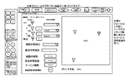
具体的には、実施例として次のようなものが考えられる(図59参照)。
チャートは一つ以上のコラムに最上位タイムゾーンかフィールドゾーンを割り付ける。コラムはオブジェクト割り付けエリアと下位コラム割り付けエリアに分割される。下位コラム割り付けエリアには更に被包含関係を為す同種のゾーンを割り付け分割する事が出来る。オブジェクト割り付けエリアにはオブジェクトアダプタが並びオブジェクトを配置できる。各オブジェクトは割り付けエリアでの位置関係(シーケンスな配置順や隣接関係)、実施順を制御したり遷移情報を記述する記述子オブジェクトやオブジェクト追加マーカーを適切な位置に配置する事によって遷移矢とゾーンによるものと同様のゾーンによって構造化された解釈を行う。またこの画面は見易い様にコラムごとに表示制御を行う事が出来る。この表示制御に関してはサブ画面もしくはウィンドウを開く形にしても良い。
Here, the descriptor for describing the scenario chart can include the site arrangement information. The part arrangement information can indicate the connection relationship between the descriptor and another descriptor, and the descriptor and another descriptor part. Regarding the placement of objects, the chart screen is divided into object adapters or additional description forms, small screens are added and the relationships between the adapters, the adjacency relationships of objects have zone inclusion relationships and connection relationship information, and the objects are attached to the adapters. The above function can also be realized by the arrangement.
Specifically, the following can be considered as an example (see FIG. 59).
The chart assigns the top time zone or field zone to one or more columns. The column is divided into an object allocation area and a lower column allocation area. In the lower column allocation area, zones of the same type that form an inclusive relationship can be further allocated and divided. Object adapters can be lined up in the object allocation area to place objects. Each object has a transition arrow and a zone by arranging a descriptor object or an object addition marker that controls the positional relationship (sequence arrangement order or adjacency relationship) and execution order in the allocation area and describes the transition information at an appropriate position. Makes a zone-structured interpretation similar to that of. In addition, the display of this screen can be controlled for each column so that it is easy to see. Regarding this display control, a sub screen or a window may be opened.
また、前記チャート図解釈部が解釈する内容としては、「コンテンツおよび前記記述子の前記タイムゾーンに対しての包含関係」のほかに、前記タイムゾーンの構造、前記チャートに配置されたフィールドゾーン情報、コンテンツおよび前記記述子の他のアイコンへの部位配置情報、及び結合関係(前記アイコンおよび前記アイコン部位)を含むことができる。
なお、「最上位がタイムゾーンの場合は前記フィールドゾーンを、最上位がフィールドゾーンの場合は前記タイムゾーンを参照情報として追加することができる。」そしてそれは、「構造化要素がタイムゾーンなら被包含要素のフィールドゾーン包含関係情報を双方に付記し、構造化要素がフィールドゾーンなら被包含要素のタイムゾーン包含関係情報を双方に付記し、」と書き換えることができる。
In addition to the "content and the inclusion relationship of the descriptor with respect to the time zone", the contents to be interpreted by the chart diagram interpretation unit include the structure of the time zone and the field zone information arranged in the chart. , Content and site placement information for the descriptor to other icons, and binding relationships (the icon and the icon site).
In addition, "If the highest level is a time zone, the field zone can be added, and if the highest level is a field zone, the time zone can be added as reference information." The field zone inclusion relation information of the containing element is added to both sides, and if the structured element is a field zone, the time zone inclusion relation information of the included element is added to both sides. "
さらに、ユーザチェック部を有し、
イベント参加者が、自分が通過中のノードに対応した二次元バーコードページを生成選択する。これによって、自分の状況を、管理者や他のユーザが対応可能な形で管理者や他ユーザに告知することを可能とする。
In addition, it has a user check section.
Event participants select to generate a 2D barcode page corresponding to the node they are passing through. This makes it possible to notify the administrator and other users of their situation in a form that can be handled by the administrator and other users.
ユーザチェック部(2-11,2-12)を設けることにより、イベント管理においてはノード毎のイベント参加者通過情報をイベントモニター(該当項参照)においてリアルタイムにコンテキスト毎に集合的に把握、或いは緊急事態発生を感知できるので管理者トリガ、或いはイベントモニターの緊急対応手段をもってイベントの進行を制御する事が出来る。
また参加者も2-11で自分の通過中のノードに対応した二次元バーコードページを生成選択する事によって自分の状況をユーザチェック2-12によって類型化されたシステムによって対応可能な形で管理者や他ユーザに告知できる。
By providing a user check unit (2-11, 2-12), in event management, event participant passage information for each node can be collectively grasped for each context in real time on the event monitor (see the relevant section), or urgent Since the occurrence of a situation can be detected, the progress of the event can be controlled by an administrator trigger or an emergency response means of the event monitor.
Participants also manage their situation in a form that can be handled by the system typified by user check 2-12 by generating and selecting a two-dimensional bar code page corresponding to the node they are passing through in 2-11. Can be notified to other users and users.
また、本発明にかかるイベント管理システムは、
イベントの構成単位であるシナリオの実行、イベント参加者端末とのメッセージ送受信、イベント参加者端末の位置情報処理、イベント進行記録、ログデータ収集、広告配信のうち少なくとも1以上を実行管理するイベント実行管理API、
及び
前記イベント実行管理APIによる操作対象である端末、機器、物品、建物、場所、移動手段、通信手段のうち少なくとも1以上を含む物理的リソースを各々識別して管理するリソース管理APIを格納するAPIデータベースと、
イベント実行プログラム及び当該イベント実行中に生じたログデータを格納するイベントデータベースと、
API提供者端末から所定のAPI定義仕様に適合するAPIを受信し前記APIデータベースに登録するAPI登録処理部と、
イベント生成者端末に対して所定のイベント定義仕様、及び前記APIデータベースに格納されたAPIのうち任意に選択されたAPIを送信し、イベント生成者端末において前記イベント定義仕様に従い受信したAPIをコンポーネントとして生成されるイベント実行プログラムを受信するイベント生成処理部と、
前記生成されたイベント実行プログラムのうち、当システムにおける実行可能性の所定基準及び管理者が任意で設定するイベントの妥当性基準に適合するイベント実行プログラムを前記イベントデータベースに登録するイベント登録処理部と、
ネットワークを通じてイベント参加者端末との間でイベント実行に必要な又はイベント実行に関連する情報の送受信を行う通信処理部とを備えたイベント管理システムであって、
前記イベント実行プログラムのモジュールによって重層化されたオブジェクトの動作を各モジュールに付属するシナリオに前記イベント生成者が記述するものであり、
前記シナリオを記述するための記述子を用いるものであり、
前記イベント管理システムは、さらにシナリオ構造解釈部と解析構造体生成部とを備え、
前記シナリオ構造解釈部は、
完成したシナリオにおいて、コンテンツおよび前記記述子の他の記述子への部位配置情報、及び前記記述子又は前記記述子部位の結合関係を解釈し、
前記解析構造体生成部は、
前記シナリオ構造解釈部が解釈した情報に従って、
前記コンテンツおよび前記記述子を構造体の該当位置に要素としてプロパティ情報と共にリスト化し、
部位配置された前記記述子を各要素(プロパティ)の子要素として追加し、
遷移情報をプロパティと指示情報として双方向から追加し、
これらにより解析構造体を生成し、モジュールに固有の構造体とし、マークアップ言語によるプログラミングと同等のシナリオ構造解釈を実現することを特徴とする。
これにより、シナリオ作成時、シナリオ参加時のユーザインタフェースをわかりやすくしつつも、HTMLなどの構造化文書に準じた構造を有するイベント管理システムを提供できる。
Further, the event management system according to the present invention is
Event execution management that executes and manages at least one of scenario execution, which is a constituent unit of an event, message transmission / reception with an event participant terminal, position information processing of an event participant terminal, event progress recording, log data collection, and advertisement distribution. API,
And an API that stores a resource management API that identifies and manages physical resources including at least one of terminals, devices, articles, buildings, places, transportation means, and communication means that are operation targets by the event execution management API. Database and
An event execution program and an event database that stores log data generated during the execution of the event,
An API registration processing unit that receives an API conforming to a predetermined API definition specification from an API provider terminal and registers it in the API database.
A predetermined event definition specification and an API arbitrarily selected from the APIs stored in the API database are transmitted to the event generator terminal, and the API received by the event generator terminal according to the event definition specification is used as a component. The event generation processing unit that receives the generated event execution program, and
Among the generated event execution programs, the event registration processing unit that registers the event execution program that meets the predetermined feasibility criteria in this system and the event validity criteria arbitrarily set by the administrator in the event database. ,
An event management system equipped with a communication processing unit that sends and receives information necessary for event execution or related to event execution to and from event participant terminals via a network.
The event generator describes the operation of the objects layered by the module of the event execution program in the scenario attached to each module.
It uses a descriptor to describe the scenario.
The event management system further includes a scenario structure interpretation unit and an analysis structure generation unit.
The scenario structure interpretation unit
In the completed scenario, interpret the part placement information for the content and other descriptors of the descriptor, and the binding relationship of the descriptor or the descriptor part.
The analysis structure generation unit
According to the information interpreted by the scenario structure interpretation unit
The contents and the descriptor are listed together with the property information as elements at the corresponding positions in the structure.
Add the part-located descriptor as a child element of each element (property),
Add transition information as property and instruction information from both directions,
It is characterized by generating an analysis structure by these, making it a structure unique to a module, and realizing a scenario structure interpretation equivalent to programming in a markup language.
This makes it possible to provide an event management system having a structure similar to a structured document such as HTML while making the user interface at the time of scenario creation and scenario participation easy to understand.
前記イベント生成者が複数存在し、それらを管理者ユーザとして扱い、イベントを利用する一般ユーザと、イベントを生成する管理者ユーザとを区別して扱い、
前記イベント管理システムは、さらに管理者ユーザが一般ユーザに対して付与する利益であるポイントや称号を管理するポイント管理部を有し、
前記ポイント管理部は、
個々のイベント利用時に管理者ユーザが設定するポイントや称号を他の管理者の生成するイベントに持ち越せることを特徴とする。
これにより、複数のイベント、複数のイベント生成者が混在する中で、ポイントや称号を共有することが可能となる。
There are a plurality of event generators, and they are treated as administrator users, and general users who use events and administrator users who generate events are treated separately.
The event management system further has a point management unit that manages points and titles that are profits given to general users by the administrator user.
The point management department
The feature is that the points and titles set by the administrator user when using each event can be carried over to the event generated by another administrator.
This makes it possible to share points and titles in a mixture of multiple events and multiple event generators.
前記イベント生成処理部は、
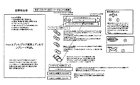
前記イベント生成の際に、管理者ユーザが行うシナリオ作成は、フローチャートを配置する様にグラフィカルに行うことが可能であり、操作はオブジェクトを収納したパレットブロックからチャートを配置するフィールドブロックにドラッグ&ドロップすることによって実現することを特徴とする。
これにより、直感的なプログラミングを可能とする。
The event generation processing unit
When the event is generated, the scenario creation performed by the administrator user can be performed graphically as if a flowchart is arranged, and the operation is dragged and dropped from the palette block containing the object to the field block in which the chart is arranged. It is characterized by being realized by doing.
This enables intuitive programming.
前記イベント生成処理部は、
前記ドラッグ&ドロップの操作の際に、現実の配信時に問題となる時間と場所の制限を取り込み、実現不可能な場合には、当該操作が不能であることをビジュアルに操作者に通知することを特徴とする。
これにより、操作不能となるイベントの生成を未然に回避できる。
ここで、「ビジュアルに操作者に通知する」ことは、当該警告を意味する表示を積極的に操作者に表示する場合のみならず、ドラッグ&ドロップの操作をしようとしても、当該アイコンなどをその場所に置くという操作ができないこと(置こうとしても置けないこと)による消極的な表示をも含む。
The event generation processing unit
At the time of the drag-and-drop operation, the time and place restrictions that are problematic at the time of actual distribution are taken in, and if it is not feasible, the operator is visually notified that the operation is impossible. It is a feature.
As a result, it is possible to avoid the generation of an event that becomes inoperable.
Here, "visually notifying the operator" is not only when the operator is actively displayed with a display meaning the warning, but also when he / she tries to perform a drag-and-drop operation, the icon or the like is displayed. It also includes a passive display due to the inability to place it in a place (it cannot be placed even if it is tried).
前記イベント管理システムは、前記イベントが実行されている際に前記一般ユーザが当該イベントに参加することを処理する一般ユーザ参加処理部をさらに有し、
前記一般ユーザ参加処理部は、
前記一般ユーザが参加者として行動して、管理者ユーザが生成したイベントにトリガ発生をする処理をアイコンを画面上に配置することにより実行することが可能であることを特徴とする。
これにより、一般ユーザがイベントに参加することを一般ユーザが認識、自覚しやすい。
The event management system further includes a general user participation processing unit that processes the general user to participate in the event when the event is being executed.
The general user participation processing unit
It is characterized in that the general user acts as a participant and can execute a process of triggering an event generated by an administrator user by arranging an icon on the screen.
As a result, it is easy for the general user to recognize and be aware that the general user participates in the event.
前記イベント生成処理部は、
イベントに必要な計算処理や条件処理を条件評価矢と代入矢によるオブジェクト間の遷移、すなわち結合操作で実行可能とすることを特徴とする。
これにより、ビジュアル化したプログラミングの範囲を広げることができる。
The event generation processing unit
It is characterized in that the calculation processing and conditional processing required for the event can be executed by the transition between objects by the conditional evaluation arrow and the substitution arrow, that is, the join operation.
This allows the scope of visualized programming to be expanded.
前記イベント管理システムは、前記イベントに参加する前記一般ユーザの相互作用を管理する一般ユーザ相互作用管理部をさらに有し、
前記一般ユーザ相互作用管理部は、
複数参加者間の相互作用を管理する全体処理用のグラフィカルな作成アイコンを利用してメンバスコープの遷移系列での都度評価を通じてその時点のサービス対象者を確定可能であることを特徴とする。
これにより、イベントの参加者へのサービス提供の範囲を直感的に絞り込むことが可能である。
The event management system further includes a general user interaction management unit that manages the interaction of the general users who participate in the event.
The general user interaction management unit
The feature is that the service target person at that time can be determined through the evaluation each time in the transition series of the member scope by using the graphical creation icon for the whole process that manages the interaction between multiple participants.
This makes it possible to intuitively narrow down the scope of service provision to event participants.
前記イベント管理システムは、前記イベントに参加する前記一般ユーザの行動を確認するユーザ行動確認部をさらに有し、
前記ユーザ行動確認部は、
前記一般ユーザが二次元バーコード、一次元バーコード、ICチップ、RFID又は赤外線情報などのうちのいずれか一つを端末で読み取って送信することにより、前記一般ユーザの行動を確認可能であり、
前記イベント生成処理部は、当該処理を可能とすべく、前記一般ユーザの行動確認をアイコンを利用してシナリオに組み込み可能とすることを特徴とする。
これにより、土地に定着した二次元バーコード、一次元バーコード、ICチップ、RFID又は赤外線情報などのうちのいずれか一つとの関係で、ユーザの行動確認をより確かなものとすることができる。
The event management system further has a user behavior confirmation unit that confirms the behavior of the general user who participates in the event.
The user behavior confirmation unit
The general user can confirm the behavior of the general user by reading and transmitting any one of a two-dimensional bar code, a one-dimensional bar code, an IC chip, RFID, infrared information, and the like with a terminal.
The event generation processing unit is characterized in that the behavior confirmation of the general user can be incorporated into a scenario by using an icon in order to enable the processing.
As a result, it is possible to make the user's behavior confirmation more reliable in relation to any one of the two-dimensional bar code, the one-dimensional bar code, the IC chip, the RFID, the infrared information, etc., which are fixed on the land. ..
前記イベント生成処理部は、前記一般ユーザの行動管理に必要なメッセージ配信を重要度に応じてユーザに認識させるよう、シナリオ作成し、
前記ユーザ行動確認部は、前記一般ユーザの行動管理に必要なメッセージ配信を重要度に応じてユーザに認識させるよう、シナリオ実行中の前記一般ユーザの行動遷移の管理を行うことを可能としたことを特徴とする。
これにより、イベントに参加する一般ユーザに対して、本人の趣味嗜好、状況に合わせた案内をメッセージ配信により行い、注意喚起することが可能となる。
The event generation processing unit creates a scenario so that the user recognizes the message delivery necessary for the behavior management of the general user according to the importance.
The user behavior confirmation unit has made it possible to manage the behavior transition of the general user during scenario execution so that the user recognizes the message delivery required for the behavior management of the general user according to the importance. It is characterized by.
As a result, it is possible to alert general users who participate in the event by delivering a message according to their hobbies, tastes, and situations.
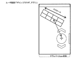
前記イベント生成処理部は、タブとスクロール管理アイコンを利用した親指のみで携帯タッチパネル操作を行って、イベント生成又はイベント参加が可能なユーザインターフェイスを有することを特徴とする。
これにより、片手で携帯端末を保持しつつ、操作が可能となる。
The event generation processing unit is characterized by having a user interface capable of generating or participating in an event by operating the mobile touch panel only with the thumb using the tab and the scroll management icon.
As a result, it is possible to operate the mobile terminal while holding it with one hand.
前記イベント生成処理部は、
前記シナリオを記述するに際して、基本記述(レベル1)、高度管理導入(レベル2)、全体処理導入(レベル3)と三層のレベルの制限をユーザインタフェースもしくはユーザ資格でコントロールするように構成し、
基本記述(レベル1)では、ユーザの行動を制約せず行動に従ったガイドを行い、 高度管理導入(レベル2)では、ユーザの行動をイベントの進行のために制御し、
全体処理導入(レベル3)では、複数のユーザの間の相互作用を制御するようにしたことを特徴とする。
これにより、ユーザの用いるインタフェースまたはユーザ資格により、プログラミング可能なレベルをコントロールできる。
ここで、レベル2とレベル3とは、どちらが難易度が上というわけではない。いずれも並列的にレベル1よりも難易度の高い記述である。すなわち、基本記述よりも難易度の高い記述として、行動管理と、参加者相互作用管理がある。
The event generation processing unit
When describing the scenario, the basic description (level 1), advanced management introduction (level 2), overall processing introduction (level 3), and three-layer level restrictions are configured to be controlled by the user interface or user qualifications.
In the basic description (level 1), the user's behavior is not restricted and the guide is performed according to the behavior, and in the advanced management introduction (level 2), the user's behavior is controlled for the progress of the event.
The introduction of overall processing (level 3) is characterized in that the interaction between a plurality of users is controlled.
This allows the programmable level to be controlled by the interface or user credentials used by the user.
Here,
前記イベント生成処理部は、
グラフィカルに作成したシナリオ部品をライブラリ登録する共用モジュールに転換することが可能である。
それにより、プログラムの一部をテンプレート化することが可能である。
The event generation processing unit
It is possible to convert graphically created scenario parts into shared modules that are registered in the library.
Thereby, it is possible to make a part of the program into a template.
前記イベント生成処理部は、
時間に関するオブジェクトであるタイムゾーンの構造を示す通常の編集画面と、
空間に関するオブジェクトであるフィールドゾーンの構造を示すマップタイプの編集画面を相互に切り替えて、編集可能であることを特徴とする。
それにより、状況に応じて、タイムゾーンとフィールドゾーンとを切り替えることにより直感的に理解しやすい編集作業を可能とする。
The event generation processing unit
A normal edit screen showing the structure of the time zone, which is an object related to time,
The feature is that the map type editing screens showing the structure of the field zone, which is an object related to space, can be switched between each other and edited.
As a result, it is possible to perform editing work that is intuitively easy to understand by switching between the time zone and the field zone according to the situation.
前記イベント生成処理部は、
参加者の携帯する端末機器の端末アプリを利用した相互の接触確認プロセス(ユーザチェック)を設定することが可能であり、
管理者ユーザが一般ユーザとの間でユーザチェックをすることで、当該一般ユーザが行動をすることの制限を課すことができ、
一般ユーザ同士のユーザチェックにより、グルーピングがなされることを特徴とする。
The event generation processing unit
It is possible to set a mutual contact confirmation process (user check) using the terminal application of the terminal device carried by the participant.
By having the administrator user check the user with the general user, it is possible to impose restrictions on the general user's actions.
It is characterized in that grouping is performed by user checks between general users.
前記イベント生成処理部は、
グローバルトリガ、RSS、ユーザ情報付RSS、連携システムからのデータ、ユーザ情報付データ、シナリオステイタスのいずれかにユーザの個別シナリオインスタンスを生成する機能を付与したエントリートリガによりユーザの個別インスタンスを発生させるのみならず、
ユーザが携帯する端末アクション、フィールドインのみを受け取るエントリートリガであるローカルエントリィにより、ローカルエントリィプロセスを開始することができることを特徴とする。
これにより、参加者が地理的に参加しやすいイベントに二次元バーコード等の付された看板、ポスターやデジタルサイネイージを介してあるいはそれらが視界に入った時点での端末操作によって参加することができる。
The event generation processing unit
Only generate an individual instance of a user by an entry trigger that has a function to generate an individual scenario instance of the user in any of global trigger, RSS, RSS with user information, data from linked system, data with user information, and scenario status. Not
The feature is that the local entry process can be started by the local entry which is an entry trigger that receives only the terminal action and the field-in carried by the user.
As a result, participants can participate in events that are geographically easy to participate in through signs with two-dimensional bars, posters, digital signage, or by operating the terminal when they are in sight. it can.
前記ローカルエントリィの位置指定情報は、範囲情報のほかに、位置ポイント情報を特定することができ、
位置ポイント情報は、ユーザの指定、又は範囲の重心などの位置指定情報から導かれるものであることを特徴とする。
これにより、通常のエントリとは区別した扱いが可能となる。
In addition to the range information, the position designation information of the local entry can specify the position point information.
The position point information is characterized in that it is derived from the position designation information such as the user's designation or the center of gravity of the range.
This makes it possible to treat the entry separately from the normal entry.
前記ローカルエントリィプロセスを実現する際に用いるマップであるトリガマップ上には、参加中のコンテキストの特定されたフィールドゾーン情報のほかにコンテキストを特定された稼働中のローカルエントリィ位置情報が表示され、
表示されるローカルエントリィ情報は管理者側が無制限な範囲指定を行わないようにローカルエントリィの一ポイント情報に限定し、一つのシナリオ、あるいは管理者ユーザから提供される位置ポイント情報を制限することを特徴とする。
これにより、マップ上におけるローカルエントリィの扱いを可能とすることができる。
On the trigger map, which is a map used to realize the local entry process, in addition to the specified field zone information of the participating context, the running local entry position information with the specified context is displayed.
The displayed local entry information is limited to one point information of the local entry so that the administrator does not specify an unlimited range, and one scenario or the position point information provided by the administrator user is limited. And.
This makes it possible to handle local entries on the map.
生成された前記解析構造体に対応し、当該構造を継承する形で前記イベント参加者の参加ログを、前記イベントに対するコンテキストでクラス化された時間と場所で構造化されたログとして生成するログ生成部とログ解析部とをさらに有し、
前記ログ生成部は、参加者のゾーン、モジュール通過情報とサービス利用情報をログとして生成し、
前記ログ解析部は、
全ての参加者の通過情報を集約して特定のノードの重要性の解析、遷移先、遷移元との関連情報を解析し、
又は特定の参加者の行動をノードのコンテンツ情報や管理者のノードに付与するコンテキスト情報から解析して参加者の行動特性、嗜好を抽出することができる。
これにより、ビッグデータの活用又は特定参加者の管理を可能とする。
Log generation that corresponds to the generated analysis structure and inherits the structure to generate the participation log of the event participant as a log structured with the time and place classified in the context for the event. It also has a section and a log analysis section.
The log generation unit generates a participant's zone, module passage information and service usage information as a log.
The log analysis unit
By aggregating the passing information of all participants, analyzing the importance of a specific node, analyzing the information related to the transition destination and transition source,
Alternatively, the behavior characteristics and preferences of the participants can be extracted by analyzing the behavior of a specific participant from the content information of the node and the context information given to the node of the administrator.
This makes it possible to utilize big data or manage specific participants.
ログ生成の実施例
1:参加者のゾーン、モジュール通過情報とサービス利用情報をログとして生成する(これは参加者毎のリストでも元構造体の通過参加者情報として保存しても良い)。通過情報は元の構造体との対応関係を伴う。
2:解析時には全ての参加者の通過情報を集約して特定のノードの重要性の解析、遷移先、遷移元との関連情報を解析する。
3:或いはある参加者の行動をノードのコンテンツ情報や管理者のノードに付与するコンテキスト情報から解析して参加者の行動特性、嗜好を抽出しても良い。
Example 1: Participant zone, module passage information and service usage information are generated as a log (this may be saved as a list for each participant or as passage participant information of the original structure). The transit information has a correspondence with the original structure.
2: At the time of analysis, the passage information of all participants is aggregated to analyze the importance of a specific node, and analyze the information related to the transition destination and the transition source.
3: Alternatively, the behavior of a participant may be analyzed from the content information of the node and the context information given to the node of the administrator to extract the behavior characteristics and preferences of the participant.
さらに、イベントモニタ部及び緊急対応部を有し、
前記イベントモニタ部は、
ノード毎のイベント参加者通過情報をイベントモニタにおいてリアルタイムにコンテキスト毎に集合的に把握、或いは緊急事態発生を感知し、
前記緊急対応部は、
ノードごとの緊急事態に対応するためのイベントの進行の制御をすることができる。
これにより、リアルタイムなノード毎のイベント管理を可能とする。
イベントに対するコンテキストでクラス化された時間と場所で構造化されたログは解析とイベントでの参加者管理が容易でありビッグデータでの活用を効率的に行う事が出来る。
In addition, it has an event monitor unit and an emergency response unit.
The event monitor unit
Event participant passage information for each node is collectively grasped for each context in real time on the event monitor, or an emergency occurrence is detected.
The emergency response department
It is possible to control the progress of events to respond to emergencies on a node-by-node basis.
This enables real-time event management for each node.
Logs structured by time and place classified in the context of the event are easy to analyze and manage participants at the event, and can be efficiently used for big data.
さらに、ユーザチェック部を有し、イベント参加者が、自分が通過中のノードに対応した二次元バーコードページを生成選択する。これによって、自分の状況を、管理者や他のユーザが対応可能な形で管理者や他ユーザに告知することを可能とする。
前記一般ユーザ参加処理部は、ユーザが登録したタグを択一的公式タグによって類型化し、参加者属性として登録させる。これにより参加者の属性のチェックを実行することができる。
前記イベント処理部が計算処理の際に扱う属性やデータは、表計算の表、又はデータベースのコラムを利用した行列計算、クエリー計算を含む。これにより、外部の情報など、広く利用することが可能になる。
前記モジュール、前記タイムゾーン及び前記フィールドゾーンは、内部ロジックによる期待時間要素を有し、前記イベント生成処理部は、期待時間計算処理部をさらに有し、前記期待時間計算処理部が計算した結果に基づいて、シナリオの妥当性を判断することを特徴とする。
さらに、場所イベント管理部を有し、前記場所イベント管理部は、その場所と時間制限情報を規格化することにより、各場所イベントの開始もしくは想定開始時間を算出し、それにより、遅延管理、推奨ルート設定又は未来タイムライン表示のうちの少なくとも一つを可能にすることを特徴とする。
前記場所イベント管理部は、マップ上に配置された特定のカテゴリーのユーティリティポイントリストから特定された指定ポイントへの誘導を行うことを特徴とする。
前記場所イベント管理部は、複数の参加者をグループ化し、グループ行動に必要なユーティリティ機能を提供することを特徴とする。
アイコンを、遷移を表現するグラフィックの適切な位置に配置することによってイベント処理時に相互作用のトランザクション処理用のキーを自動生成することを特徴とする。
アイコンを使用してHTMLエディタにリンクやデータ受け渡し用のタグを生成することを特徴とする。
グラフィカルにモジュール内外のイベント処理と引数、戻り値を設定することを特徴とする。
参加者の位置情報処理について所在タイル登録処理とイベント処理用タイル指定をおこなうことによって計算量を削減することを特徴とする。
タブのリストとページを結合したランディングページを相互に遷移させて、斜めの遷移バー又は扇状の遷移バーのうちのいずれかを利用することにより、スクロール管理アイコンを用いずに、スクロールを実行することを特徴とする。
解釈構造体の出力及び入力について、マークアップ言語、構造を入れ子で記述出来る言語、JSON(javascript object notation)又はオブジェクト構造を記述できるデータ記述言語を利用して、記述を包含するゾーンに対応するオブジェクトの記法を設定し、入れ子構造もしくは所属関係を示すリスト情報を付加することを特徴とする。
完成したチャート図において、コンテンツおよび前記記述子の他のアイコンへの部位配置情報、及び前記遷移矢の結合関係(前記アイコンおよび前記アイコン部位)を解釈することを特徴とする。
Further, it has a user check unit, and an event participant generates and selects a two-dimensional bar code page corresponding to the node through which he / she is passing. This makes it possible to notify the administrator and other users of their situation in a form that can be handled by the administrator and other users.
The general user participation processing unit categorizes the tags registered by the user by alternative official tags and registers them as participant attributes. This makes it possible to check the attributes of participants.
The attributes and data handled by the event processing unit in the calculation processing include a matrix calculation and a query calculation using a spreadsheet table or a database column. This makes it possible to widely use external information and the like.
The module, the time zone, and the field zone have an expected time element by internal logic, the event generation processing unit further has an expected time calculation processing unit, and the result calculated by the expected time calculation processing unit is obtained. It is characterized by judging the validity of the scenario based on it.
Further, it has a place event management unit, and the place event management unit calculates the start or estimated start time of each place event by standardizing the place and time limit information, thereby delay management and recommendation. It is characterized by enabling at least one of route setting or future timeline display.
The location event management unit is characterized in that it guides to a specified designated point from a list of utility points of a specific category arranged on the map.
The place event management unit is characterized in that a plurality of participants are grouped and utility functions necessary for group actions are provided.
By arranging the icon at an appropriate position in the graphic representing the transition, the key for transaction processing of the interaction is automatically generated at the time of event processing.
It is characterized by generating a link or a tag for data transfer in the HTML editor by using an icon.
It is characterized by graphically setting event processing inside and outside the module, arguments, and return values.
Participant's position information processing is characterized by reducing the amount of calculation by performing location tile registration processing and event processing tile designation.
Scrolling without using the scroll management icon by transitioning the landing page that combines the list of tabs and the page to each other and using either the diagonal transition bar or the fan-shaped transition bar. It is characterized by.
For the output and input of the interpretation structure, use the markup language, the language that can describe the structure in a nested manner, JSON (javascript object notation) or the data description language that can describe the object structure, and the object corresponding to the zone containing the description. It is characterized in that the notation of is set and list information indicating a nested structure or affiliation relationship is added.
In the completed chart diagram, it is characterized in that the part arrangement information on the content and the other icon of the descriptor and the connection relationship of the transition arrow (the icon and the icon part) are interpreted.
以上、説明したように、本発明のイベント管理システムは、シナリオ作成時、シナリオ参加時のユーザインタフェースをわかりやすくしつつも、HTMLなどの構造化文書に準じた構造を有するイベント管理システムを提供できる。 As described above, the event management system of the present invention can provide an event management system having a structure conforming to a structured document such as HTML while making the user interface at the time of scenario creation and scenario participation easy to understand. ..
以下、添付図面を参照しながら、本発明の管理システムを実施するための最良の形態を詳細に説明する。までは、本発明の実施の形態を例示する図であり、これらの図において、同一の符号を付した部分は同一物を表わし、基本的な構成及び動作は同様であるものとする。
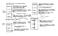
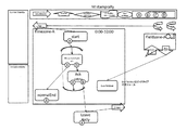
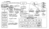
図57は、イベント管理システムのハードウェア構成を示す図である。図57の中央に楕円で示すインターネット網には、サーバ(サーバコンピュータ)10、イベント作成をする管理者ユーザが管理者ユーザアカウントを取得してサーバ10にアクセスする管理者ユーザ端末21,22,23,24、一般ユーザ端末31,32,33,34を示している。管理者ユーザ端末、一般ユーザ端末は、いわゆるスマホ、またはタブレットコンピュータであり得る。図57では、端末が直接インターネットとやりとりしているように描いているが、ワイファイ機器を介してインターネットにつながるのでもよい。また、携帯電話ネットワークを介してインターネットにつながるのでもよい。
Hereinafter, the best mode for implementing the management system of the present invention will be described in detail with reference to the accompanying drawings. Up to this point, the drawings illustrate the embodiments of the present invention, and in these figures, the parts with the same reference numerals represent the same objects, and the basic configuration and operation are the same.
FIG. 57 is a diagram showing a hardware configuration of the event management system. In the Internet network shown by the ellipse in the center of FIG. 57, the server (server computer) 10 and the administrator user who creates the event acquire the administrator user account and access the
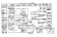
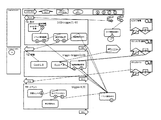
図58は、イベント管理システムを構成するサーバコンピュータ10の構成を示す図である。イベントの構成単位であるシナリオの実行、イベント参加端末とのメッセージ送受信、イベント参加者端末の位置情報処理、イベント進行記録、ログデータ収集、広告配信などを実行管理するイベント実行管理API(アプリケーションプログラムインタフェース)、端末、機器、物品、建物、場所、移動手段、通信手段などの物理的リソースを各々識別して管理するリソース管理APIを格納するAPIデータベース装置51、イベント実行プログラム及びイベント実行中に生じたログデータを格納するイベントデータベース装置52、ユーザのアカウント情報などを有するユーザデータベース装置53、ポイントに関する情報を有するポイントデータベース装置54を有する。
さらに、API提供者端末から所定のAPI定義仕様に適合するAPIを受信し前記APIデータベースに登録するAPI登録処理部61を有する。
また、イベント生成者端末に対して所定のイベント定義仕様、及び前記APIデータベースに格納されたAPIのうち任意に選択されたAPIを送信し、イベント生成者端末において前記イベント定義仕様に従い受信したAPIをコンポーネントとして生成されるイベント実行プログラムを受信するイベント生成処理部62を有する。
前記生成されたイベント実行プログラムのうち、当システムにおける実行可能性の所定基準及び管理者が任意で設定するイベントの妥当性基準に適合するイベント実行プログラムを前記イベントデータベースに登録するイベント登録処理部63を有する。
ネットワークを通じてイベント参加者端末との間でイベント実行に必要な又はイベント実行に関連する情報の送受信を行う通信処理部64を有する。
完成したチャート図において、前記タイムゾーンの構造、前記チャートに配置されたフィールドゾーン情報、コンテンツおよび前記記述子の前記タイムゾーンに対しての包含関係、コンテンツおよび前記記述子の他のアイコンへの部位配置情報、及び前記遷移矢の結合関係(前記アイコンおよび前記アイコン部位)を解釈するチャート図解釈部65を有する。
前記チャート図解釈部が解釈した情報に従って、
前記タイムゾーンの入れ子関係を解析してプレーンのフィールドを最上位タイムゾーンとしてプロパティ情報と共に構造化し、
前記フィールドゾーンを最上位の要素として追加し、
それぞれの前記タイムゾーンに包含されたコンテンツおよび記述子を構造体の該当位置に要素としてプロパティ情報と共にリスト化し、
部位配置された前記アイコンを各要素(プロパティ)の子要素として追加し、
遷移情報をプロパティと指示情報として双方向から追加し、
これらにより解析構造体を生成し、チャート、すなわちモジュールに固有の構造体とし、マークアップ言語によるプログラミングと同等のチャート解釈を実現する解析構造体生成部66を有する。なお、この解析構造体を生成せずに、モジュール単位のインタープリタ言語としての機能を有するものとしてもよい。
管理者ユーザが一般ユーザに対して付与する利益であるポイントや称号を管理するポイント管理部67を有する。ここで、ポイントは、たとえば、電子マネーに変換できるなど、金銭的価値をもつものである。称号は、名誉的な肩書きである。
イベントが実行されている際に一般ユーザが当該イベントに参加することを処理する一般ユーザ参加処理部68を有する。
イベントに参加する一般ユーザの相互作用を管理する一般ユーザ相互作用管理部69を有する。
イベントに参加する一般ユーザの行動を確認するユーザ行動確認部70を有する。
FIG. 58 is a diagram showing a configuration of a
Further, it has an API
In addition, a predetermined event definition specification and an API arbitrarily selected from the APIs stored in the API database are transmitted to the event generator terminal, and the API received by the event generator terminal in accordance with the event definition specification is transmitted. It has an event
Among the generated event execution programs, the event
It has a
In the completed chart diagram, the structure of the time zone, the field zone information arranged on the chart, the inclusion relationship of the content and the descriptor with respect to the time zone, the part of the content and the descriptor to other icons. It has a chart
According to the information interpreted by the chart diagram interpreter
Analyze the nesting of the time zones and structure the plain field as the top-level time zone together with the property information.
Add the field zone as a top-level element
The contents and descriptors included in each of the time zones are listed together with the property information as elements at the corresponding positions in the structure.
Add the icon placed in the part as a child element of each element (property),
Add transition information as property and instruction information from both directions,
It has an analysis
It has a
It has a general user
It has a general user
It has a user
以下、本発明の管理システムをサーバコンピュータと、ユーザの端末とをインターネットで接続して構成する場合に、主にサーバコンピュータにインストールするコンピュータプログラムの仕様を中心に説明する。 Hereinafter, when the management system of the present invention is configured by connecting the server computer and the user's terminal via the Internet, the specifications of the computer program to be installed on the server computer will be mainly described.
≪目次≫
1:概念記述
1-1:サービスのユースケース(図38、図39、図40、図41、図42、図43、図44、図45、図46参照)
1-2:シナリオ利用の流れ(管理者/ユーザ)
1-3:アカウント(管理者/ユーザ)
1-4:特徴
1-4-1:シナリオ構造とオブジェクトのスコープ
1-5:システム構成
1-6:重要/共通ロジック/ビジネスロジック
2:ユーザ画面
2-1:画面遷移
2-1-1:ナヴィゲーションバーの挙動
2-2:管理系画面
2-2-1:ログイン画面
2-2-2: 新規登録
2-2-3: アカウント
2-2-4: ペルソナ管理
2-2-5: ユーザホーム
2-2-6:属性ホルダ#保存属性管理
2-3:イベントホーム(イベント利用時の遷移)
2-3-1:基本フォーム
2-3-2:イベント利用時の遷移について(イベント開始画面と招待イベント参加認証プロセス)
2-3-3:招待イベント個別ホーム
2-3-4:参加イベントホーム(未開始)
2-3-5:参加イベントホーム(開始後)
2-3-6:参加終了イベントホーム(終了後)
2-4:コンテンツ
2-4-1:フル表示
2-4-2:特殊記事
2-4-3:外部サービス
2-5:リスト
2-5-1:表示中コンテントリスト(図32参照)
2-5-2:待機中コンテントリスト(図32参照)
2-5-3:参加中イベントリスト
2-5-4:招待中イベントリスト
2-5-5:イベントログリスト
2-5-6:参加イベント表示中コンテンツ
2-5-7:参加イベント待機コンテンツ
2-5-8:参加イベントコンテンツログ
2-6:トリガチェッカーとローカルエントリ
2-6-1:トリガチェッカーエントリィ
2-6-2:参加可能ローカルエントリィ
2-6-3:トリガマップ
2-6-4:ローカルエントリィ
2-7:タグについて
2-8:保存属性について
2-8-1:属性と保存属性
2-8-2:公式属性
2-8-3:タグ関連属性
2-8-4:保存推奨属性
2-9:メール配信
2-9-1:コンテント配信
2-9-2:告知配信
2-9-3:警告配信
2-9-4:プッシュ連動
2-10:トリガ(ユーザ側)
2-11:識別二次元バーコード
2-12:ユーザチェック
2-13:終了マージン
3:管理者画面
3-1:画面遷移
3-2:メインパート/管理系画面
3-2-1:ログイン/ログアウト#ログイン/ログアウト
3-2-2:新規登録
3-2-3:アカウント
3-2-4:ようこそページ
3-3:メインパート/シナリオ作成
3-3-1:概念説明
3-3-1-1-1:チャート操作
3-3-1-1-1-1:パレットアイコンドラッグ
3-3-1-1-1-1-1:チャートフィールドへの配置
3-3-1-1-1-1-2:アイコン上、アイコン部位への配置
3-3-1-1-1-2: ゾーンの配置
3-3-1-1-1-3:アイコンの画面内の移動とアイコンの変形
3-3-1-1-1-4:遷移矢の結合操作
3-3-1-1-1-5:アイコン詳細動作(クリック)
3-3-1-1-1-6:動作制限
3-3-1-1-1-7:部位
3-3-1-1-2:解釈と解析
3-3-1-1-2-1:解釈される情報
3-3-1-1-2-2:解析構造体
3-3-1-2:コンテント
3-3-1-2-1:定義、編集と操作
3-3-1-2-1-1:テンプレートとフィルアップ
3-3-1-2-1-2:コンテントの状態
3-3-1-2-2:記事とメッセージ
3-3-1-2-3:通常モジュールと例外管理
3-3-1-2-4:ネストタイプモジュールと外部モジュール
3-3-1-2-5:例外終了マージン
3-3-1-2-6:コンテントチャート上挙動個別説明
3-3-1-3:属性
3-3-1-3-1:スコープ
3-3-1-3-2:型
3-3-1-3-3:シナリオ属性
3-3-1-3-4:参加者属性
3-3-1-3-5:全体処理(図30、図31参照)属性
3-3-1-3-5-1:全体処理(図30、図31参照)属性のメンバスコープ
3-3-1-3-6:属性プロパティ属性化アイコン
3-3-1-3-7:属性チャート上挙動個別説明
3-3-1-4:ゾーン
3-3-1-4-1:ゾーンクラス化
3-3-1-4-2:タイムゾーン
3-3-1-4-2-1:タイムゾーンの終了
3-3-1-4-2-2:計算ゾーン
3-3-1-4-3:フィールドゾーン
3-3-1-4-3-1:所属フィールドゾーン
3-3-1-4-3-1:範囲設定
3-3-1-4-4:ゾーンアウトマージン
3-3-1-4-5:ゾーンおよび付随アイコンチャート上挙動個別説明
3-3-1-4-5-1-:タイムゾーン
3-3-1-4-5-2:フィールドゾーン
3-3-1-5:記述子(処理アイコンと遷移矢、トリガアイコン)
3-3-1-5-1:記述子チャート(全体処理以外)上挙動個別説明
3-3-1-6:タイミング設定
3-3-1-7:ターミナルステイタスとステイタスエミッタ
3-3-1-8:パレット
3-3-1-9:全体記述
3-3-1-9-1:全体処理(図30、図31参照)記述と全体処理(図30、図31参照)エリア
3-3-1-9-2:全体処理(図30、図31参照)インスタンス
3-3-1-9-3:メンバスコープ
3-3-1-9-4: 全体処理(図30、図31参照)モジュール
3-3-1-9-5:全体処理(図30、図31参照)タイムゾーン
3-3-1-9-6: 全体処理(図30、図31参照)配置チャート個別処理
3-3-1-9-7:全体処理(図30、図31参照)と全体処理(図30、図31参照)エリア内個別処理の相互作用
3-3-1-9-8: グループ処理
3-3-1-9-9:メンバ計算タイムゾーンと全体処理(図30、図31参照)を含んだ計算
3-3-1-9-10:全体処理(図30、図31参照)記述子
3-3-1-10:計算モジュール#シナリオ/計算チャート#計算ゾーン
3-3-1-10-1:(個別)計算チャートもしくは計算ゾーン
3-3-1-10-2:全体処理(図30、図31参照)を含めた属性計算
3-3-1-10-3:タイミング設定チャートと属性条件チャート
3-3-1-11: コンテンツログ
3-3-1-12:ログの記録
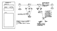
3-3-1-13:参加者タイプ(図34参照)#参加者タイプ(図34参照)決定プロセス
3-3-2:シナリオ(メイン画面)
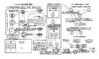
3-3-3:シナリオチャート
3-3-3-1:画面の基本構造
3-3-3-2:チャートエリア(チャートの説明)
3-3-3-3:パレットエリア(パレットの説明)
3-3-3-4:ユーティリティバー
3-3-3-5:シナリオ属性登録プロセス
3-3-4:モジュール
3-3-4-1:ネストタイプモジュール
3-3-4-2:例外管理
3-3-4-3:外部モジュール
3-3-4-3-1:外部トリガ記述モジュール
3-3-4-3-1-1:エントリィトリガとローカルエントリィ
3-3-4-3-1-2:ユーザチェック関連モジュールと利用プロセス
3-3-4-3-2:ガイドモジュール
3-3-4-3-3:ページアダプタ
3-3-4-3-4:会場危機管理システム
3-3-4-3-5:シナリオステイタスレセプタモジュール
3-3-4-4:テンプレート化
3-3-4-5:ライブラリ利用
3-3-5:記事/メッセージ
3-3-5-1: ユーザ画面
3-3-5-2:記事状態遷移
3-3-5-3:ターミナルステイタス/チェック/選択拘束
3-3-5-4:記事記述画面
3-3-5-4-1:画面パーツ
3-3-5-4-1-1:画面パーツの種類
3-3-5-5:記事メインパート
3-3-5-6:パレットエリア
3-3-5-7:ユーティリティバー
3-3-5-8:メインパート記述
3-3-5-9:テンプレート化
3-3-5-10:特殊記事
3-3-6:参加者属性管理(図33参照)
3-3-6-1:メイン画面説明
3-3-6-2:属性登録/編集画面
3-3-6-3:参加者タイプ(図34参照)登録/編集画面
3-3-7:コンテンツリスト
3-3-7-1:コンテンツリスト(メイン)
3-3-7-2:シナリオ属性リスト
3-3-7-3:サブ要素リスト
3-3-7-4:ライブラリ登録
3-3-7-5:シナリオ構造表示画面
3-3-8:二次元バーコード生成
3-3-9:概形チェック
3-4:メインパート/シナリオ管理
3-4-1:概説
3-4-1-1:実施可能シナリオ
3-4-1-2:登録推奨属性
3-4-2:実施可能シナリオ
3-4-3:参加者管理
3-4-4:登録推奨属性管理
3-4-4-1:属性承認管理
3-4-5:ライブラリ
3-4-5-1:プライベートライブラリ
3-4-5-2:標準化ライブラリ
3-4-5-3:ライブラリ画面
3-4-5-4:データアップロード
3-4-6:ユーティリティ
3-4-6-1:告知メール配信
3-4-6-2:二次元バーコード生成
3-5:メインパート/イベントモニタ
3-5-1:概説
3-5-1-1:管理者トリガ
3-5-1-2:管理者コール
3-5-2:チャートモニタ(図15参照)
3-5-2-1:チャートモニタメイン
3-5-2-2:サブモニタ(属性モニタ、参加者モニタ、ログモニタ)
3-5-2-3:ユーティリティバー
3-5-3:例外モジュールモニタ(図16参照)
3-5-4:管理者コール
3-5-5:管理者トリガ管理(図16参照)
3-6:新規登録
3-7:外部連携
X-1:ベータ時のライブラリ仕様の修正
X-2:ユーザ画面の仕様変更
X-3:多言語仕様の準備
Y-1:トリガ機能の整理統合(文書末にまとめて)
Y-2:リスト型、数値型属性の付番機能の明確化(文中で修正)
Y-3:ワイルドカードアイコンの機能の整理(文中で修正)
Y-4:ユーザ画面の仕様再変更(小画面への最適化の再検討)(文中で修正)
Y-5:概形チェックの項目候補洗い出し(#概形チェック/要件定義時に再チェック)
Y-6:アイコンプロパティの項目洗い出し(要件定義時に再チェック)
Y-7:実行可能イベントのオプション仕様のタイミング設定チャートへの統合(文中で修正)
Z-1:参加者画面整理(文書末にまとめて)
Z-2:マップタイプチャート編集画面の追加(文書末にまとめて)
Z-3:参照用サブチャート窓
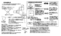
Z-4:期待時間計算(図60参照)
Z-5:対象/比較ゾーン遷移置換作業(図61参照)
Z-6:遷移矢展開作業(図62参照)
Z-7:遷移制御モードの時系列(図63参照)
Z-8:期待時間計算での要素の種別(図64参照)
Z-9:遷移系列期待時間計算(図65参照)
Z-10:期待時間合成(図66参照)
Z-11:焦点比較ゾーン内外遷移チェック(図67参照)
Z-12:実行動期待時間加算(図68参照)
≪Table of Contents≫
1: Conceptual description
1-1: Service use cases (see FIGS. 38, 39, 40, 41, 42, 43, 44, 45, 46).
1-2: Flow of scenario usage (administrator / user)
1-3: Account (administrator / user)
1-4: Features
1-4-1: Scenario structure and object scope
1-5: System configuration
1-6: Important / Common Logic / Business Logic
2: User screen
2-1: Screen transition
2-1-1: Behavior of navigation bar
2-2: Management screen
2-2-1: Login screen
2-2-2: New registration
2-2-3: Account
2-2-4: Persona management
2-2-5: User home
2-2-6: Attribute holder # Saved attribute management
2-3: Event home (transition when using an event)
2-3-1: Basic form
2-3-2: Transition when using the event (event start screen and invitation event participation authentication process)
2-3-3: Invited event individual home
2-3-4: Participating event home (not started)
2-3-5: Participating event home (after start)
2-3-6: Participation end Event home (after the end)
2-4: Content
2-4-1: Full display
2-4-2: Special article
2-4-3: External service
2-5: List
2-5-1: Displayed content list (see Fig. 32)
2-5-2: Waiting content list (see Fig. 32)
2-5-3: Participating event list
2-5-4: Invited event list
2-5-5: Event log list
2-5-6: Participating event display content
2-5-7: Participation event waiting content
2-5-8: Participating event content log
2-6: Trigger checker and local entry
2-6-1: Trigger checker entry
2-6-2: Participable local entry
2-6-3: Trigger map
2-6-4: Local entry
2-7: About tags
2-8: About save attributes
2-8-1: Attributes and storage attributes
2-8-2: Official attributes
2-8-3: Tag related attributes
2-8-4: Recommended save attributes
2-9: Email delivery
2-9-1: Content delivery
2-9-2: Notification delivery
2-9-3: Warning delivery
2-9-4: Push interlocking
2-10: Trigger (user side)
2-11: Identification two-dimensional bar code
2-12: User check
2-13: End margin
3: Administrator screen
3-1: Screen transition
3-2: Main part / management screen
3-2-1: Login / Logout # Login / Logout
3-2-2: New registration
3-2-3: Account
3-2-4: Welcome page
3-3: Main part / scenario creation
3-3-1: Conceptual explanation
3-3-1-1-1: Chart operation
3-3-1-1-1-1: Drag palette icon
3-3-1-1-1-1-1: Placement in chart field
3-3-1-1-1-1-2: Placement on the icon and on the icon part
3-3-1-1-1-2: Zone placement
3-3-1-1-1-3: Moving the icon in the screen and transforming the icon
3-3-1-1-1-4: Transition arrow join operation
3-3-1-1-1-5: Detailed icon operation (click)
3-3-1-1-1-6: Operation restrictions
3-3-1-1-1-7: Part
3-3-1-1-2: Interpretation and analysis
3-3-1-1-2-1: Information to be interpreted
3-3-1-1-2-2: Analytical structure
3-3-1-2: Content
3-3-1-2-1: Definition, editing and operation
3-3-1-2-1-1: Templates and fill-ups
3-3-1-2-1-2: Content status
3-3-1-2-2: Articles and messages
3-3-1-2-3: Normal module and exception management
3-3-1-2-4: Nested type module and external module
3-3-1-2-5: Exception end margin
3-3-1-2-6: Individual explanation of behavior on the content chart
3-3-1-3: Attributes
3-3-1-3-1: Scope
3-3-1-3-2: Type
3-3-1-3-3: Scenario attributes
3-3-1-3-4: Participant attributes
3-3-1-3-5: Overall processing (see Fig. 30 and Fig. 31) Attributes
3-3-1-3-5-1: Overall processing (see Fig. 30 and Fig. 31) Attribute member scope
3-3-1-3-6: Attribute property Attribute icon
3-3-1-3-7: Individual explanation of behavior on attribute chart
3-3-1-4: Zone
3-3-1-4-1: Zone classization
3-3-1-4-2: Time zone
3-3-1-4-2-1: End of time zone
3-3-1-4-2-2: Calculation zone
3-3-1-4-3: Field zone
3-3-1-4-3-1: Affiliation field zone
3-3-1-4-3-1: Range setting
3-3-1-4-4: Zone out margin
3-3-1-4-5: Zone and accompanying icon Behavior on chart Individual explanation
3-3-1-4-5-1-: Time zone
3-3-1-4-5-2: Field zone
3-3-1-5: Descriptor (processing icon and transition arrow, trigger icon)
3-3-1-5-1: Descriptor chart (other than overall processing) Behavior individual explanation
3-3-1-6: Timing setting
3-3-1-7: Terminal status and status emitter
3-3-1-8: Palette
3-3-1-9: Overall description
3-3-1-9-1: Overall processing (see FIGS. 30 and 31) Description and overall processing (see FIGS. 30 and 31) Area
3-3-1-9-2: Overall processing (see Figures 30 and 31) Instance
3-3-1-9-3: Member scope
3-3-1-9-4: Overall processing (see Fig. 30 and Fig. 31) Module
3-3-1-9-5: Overall processing (see Fig. 30 and Fig. 31) Time zone
3-3-1-9-6: Overall processing (see Fig. 30 and Fig. 31) Arrangement chart individual processing
3-3-1-9-7: Interaction between overall processing (see FIGS. 30 and 31) and individual processing within the area (see FIGS. 30 and 31)
3-3-1-9-8: Group processing
3-3-1-9-9: Calculation including member calculation time zone and overall processing (see FIGS. 30 and 31)
3-3-1-9-10: Overall processing (see Fig. 30 and Fig. 31) Descriptor
3-3-1-10: Calculation module # Scenario / Calculation chart # Calculation zone
3-3-1-10-1: (Individual) calculation chart or calculation zone
3-3-1-10-2: Attribute calculation including overall processing (see Fig. 30 and Fig. 31)
3-3-1-10-3: Timing setting chart and attribute condition chart
3-3-1-11: Content log
3-3-1-12: Log recording
3-3-1-13: Participant type (see Figure 34) # Participant type (see Figure 34) determination process
3-3-2: Scenario (main screen)
3-3-3: Scenario chart
3-3-3-1: Basic structure of the screen
3-3-3-2: Chart area (explanation of chart)
3-3-3-3: Pallet area (explanation of pallets)
3-3-3-4: Utility bar
3-3-3-5: Scenario attribute registration process
3-3-4: Module
3-3-4-1: Nested type module
3-3-4-2: Exception management
3-3-4-3: External module
3-3-4-3-1: External trigger description module
3-3-4-3-1-1: Entry trigger and local entry
3-3-4-3-1-2: User check related modules and usage process
3-3-4-3-2: Guide module
3-3-4-3-3: Page adapter
3-3-4-3-4: Venue crisis management system
3-3-4-3-5: Scenario Status Receptor Module
3-3-4-4: Template
3-3-4-5: Library usage
3-3-5: Article / Message
3-3-5-1: User screen
3-3-5-2: Article state transition
3-3-5-3: Terminal status / check / selective restraint
3-3-5-4: Article description screen
3-3-5-4-1: Screen parts
3-3-5-4-1-1: Types of screen parts
3-3-5-5: Article main part
3-3-5-6: Pallet area
3-3-5-7: Utility bar
3-3-5-8: Main part description
3-3-5-9: Template
3-3-5-10: Special article
3-3-6: Participant attribute management (see Fig. 33)
3-3-6-1: Main screen explanation
3-3-6-2: Attribute registration / edit screen
3-3-6-3: Participant type (see Fig. 34) Registration / edit screen
3-3-7: Content list
3-3-7-1: Content list (main)
3-3-7-2: Scenario attribute list
3-3-7-3: Sub-element list
3-3-7-4: Library registration
3-3-7-5: Scenario structure display screen
3-3-8: Two-dimensional bar code generation
3-3-9: Outline check
3-4: Main part / scenario management
3-4-1: Overview
3-4-1-1: Possible scenarios
3-4-1-2: Recommended registration attributes
3-4-2: Possible scenarios
3-4-3: Participant management
3-4-4: Registration recommended attribute management
3-4-4-1: Attribute approval management
3-4-5: Library
3-4-5-1: Private library
3-4-5-2: Standardized library
3-4-5-3: Library screen
3-4-5-4: Data upload
3-4-6: Utility
3-4-6-1: Notification email delivery
3-4-6-2: Two-dimensional bar code generation
3-5: Main part / event monitor
3-5-1: Overview
3-5-1-1: Administrator trigger
3-5-1-2: Administrator call
3-5-2: Chart monitor (see Fig. 15)
3-5-2-1: Chart monitor main
3-5-2-2: Sub monitor (attribute monitor, participant monitor, log monitor)
3-5-2-3: Utility bar
3-5-3: Exception module monitor (see Fig. 16)
3-5-4: Administrator call
3-5-5: Administrator trigger management (see Fig. 16)
3-6: New registration
3-7: External cooperation
X-1: Modification of library specifications in beta
X-2: User screen specification change
X-3: Preparation for multilingual specifications Y-1: Organization and integration of trigger functions (collected at the end of the document)
Y-2: Clarification of numbering function for list type and numeric type attributes (corrected in the text)
Y-3: Arrangement of wildcard icon functions (corrected in the text)
Y-4: Re-change of user screen specifications (reexamination of optimization for small screen) (corrected in the text)
Y-5: Identifying candidate items for the outline check (#scheme check / recheck when defining requirements)
Y-6: Identify item of icon property (recheck when defining requirements)
Y-7: Integration of optional specifications of executable events into the timing setting chart (corrected in the text)
Z-1: Participant screen arrangement (collected at the end of the document)
Z-2: Addition of map type chart edit screen (collected at the end of the document)
Z-3: Reference sub-chart window Z-4: Expected time calculation (see Fig. 60)
Z-5: Target / comparison zone transition replacement work (see FIG. 61)
Z-6: Transition arrow deployment work (see Fig. 62)
Z-7: Time series of transition control mode (see FIG. 63)
Z-8: Element type in expected time calculation (see Fig. 64)
Z-9: Transition series expected time calculation (see Fig. 65)
Z-10: Expected time synthesis (see FIG. 66)
Z-11: Focus comparison zone inside / outside transition check (see FIG. 67)
Z-12: Addition of expected execution time (see FIG. 68)
≪内容≫
1:概念記述
このサービスはイベント主催者(管理者ユーザ)が携帯端末を持った参加者(一般ユーザ)を端末配信の利用により場所やリアルな状況(コンテキスト)に応じた配信サービスを行う簡易アプリ構築の為のヴィジュアルプログラミングシステムである。
その為管理者ユーザはイベントのシナリオを作成又はライブラリからインポート後ローカライズしてイベントを実施する。その為にシステムは以下のサービスを管理者一般ユーザに提供する。
管理者ユーザ
1:イベントシナリオ作成
2:イベントシナリオ実施管理
3:イベント実施
4:イベント内で発生した価値(属性)の管理と公開、提携
5:シナリオ及びシナリオ素材のストレージ及びライブラリ提供
6:上記ライブラリでの素材の流通
7:自己サービスや施設へのイベント性を含んだローカルな誘導手段
一般ユーザ
1:携帯端末や設置端末を通じた全体でイベントを構成する配信サービスを受ける(イベントに参加する)
2:イベント内で発生した価値の管理と他イベントでの利用
3:他の連携サービスへのイベント性を含んだローカルな入口
目標とする商業的な機能は
1:ツアー支援アプリ(L1)
2:屋外イベントユーザ誘導進行管理(L1)
3:ツアー、屋外イベントグループ行動、アトラクション、希少性管理(L2~3)
4:ライブRPG(ゲーム)メイキング(モジュール資産形成)(L1〜3+アプリ)
5:ダイレクトな商業施設誘導(L1~2)
6:野外市街での業務チュートリアル(L2+アプリ)
上記のレベルについては1-4-1:シナリオのレベルを参照。(管理者ユーザ或いは開発者に必要な技能レベル)
≪Contents≫
1: Concept description This service is a simple application in which the event organizer (administrator user) provides a distribution service to participants (general users) with mobile terminals according to the location and real situation (context) by using terminal distribution. It is a visual programming system for construction.
Therefore, the administrator user creates an event scenario or imports it from the library and then localizes it to execute the event. Therefore, the system provides the following services to general administrator users.
Administrator user 1: Event scenario creation 2: Event scenario implementation management 3: Event implementation 4: Management and disclosure of values (attributes) generated in the event, tie-up 5: Storage and library provision of scenarios and scenario materials 6: Above library Distribution of materials in 7: Local guidance means including self-service and event characteristics to facilities General users 1: Receive distribution services that compose an event as a whole through mobile terminals and installed terminals (participate in events)
2: Management of value generated in the event and use in other events 3: Local entrance including event characteristics to other linked services
The target commercial function is 1: Tour support app (L1)
2: Outdoor event user guidance progress management (L1)
3: Tour, outdoor event group behavior, attraction, rarity management (L2 ~ 3)
4: Live RPG (game) making (module asset formation) (L1 ~ 3 + app)
5: Direct commercial facility guidance (L1 ~ 2)
6: Business tutorial in the outdoor city (L2 + app)
See 1-4-1: Scenario Levels for the above levels. (Skill level required for administrator users or developers)
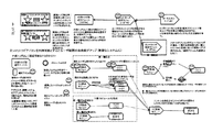
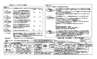
1-1:サービスのユースケース(図38、図39、図40、図41、図42、図43、図44、図45、図46参照)
サンプルアフターパーティを利用して
付近のアリーナでライブがありバーの経営者は本システムを利用して興行主が提供する素材を利用してライブ帰りの客を自店舗に誘導しようと考えた。
1:興行主が標準化ライブラリに提供するライブ関係のモジュールやデータの検索を行う。
2:検索の結果、クライマックス視聴、ライブクイズ、会場付近のローカルエントリィ(フィールドゾーン定義データ含む)が提供されていたので使用許諾を取得する。またこれらを使用するイベントメインのテンプレートも存在していたので時間、店舗の広さに合いそうなモジュールを確認しておく。
3:管理者ページのシナリオ作成(図49参照)を開き作成中のシナリオリストから新規作成をチェックする。
4:新規シナリオのシナリオページが開かれる。
5:イベントの次第を考える。
a) ライブは5時に終わるので8時過ぎに店舗内でメインとなるクイズイベントが開始される様に設計する。
b) 移動に一時間前後、受付の締切を6時に設定する。
c) クイズの開始時間は管理者(店長)の判断による。
d) テンプレートのシナリオメインの終了時にイベントが終了する。
6:シナリオチャートページを開きシナリオを作成する。
a) チェックしておいた標準化ライブラリの素材をテンプレートパレットにダウンロードする。
b) 受付、移動、店舗でのイベントの三段階になるので対応するタイムゾーンを処理パレットからドラッグしてチャート上に配置する。それぞれイベント開始から1時間、イベント開始から2時間もしくはトリガ、イベント開始から四時間半にタイムアウトを設定する。
c) 場所はこちらでローカルエントリィの範囲となるライブ会場、移動域の範囲を決めて途中離脱のチェックをする為のレストラン誘導、会場到着判定の為のレストランを作成する。処理パレットからドラッグしてチャートに配置する。なおライブ会場の範囲は興行主よりライブラリデータとして受け取る。
d) クイズ開始トリガを作る為に処理パレットから新規トリガをドラッグして管理者トリガとして配置する。
e) 配置するメッセージおよび記事(図18参照)を作成する。
f) 必要なユーザ属性を参加者属性管理(図33参照)で定義する。
g) 記事(図18参照)やモジュールなどのコンテンツをシナリオの進行上適切なタイムゾーン或いはプレーンフィールドに配置。また遷移制御の為の処理アイコンやシナリオ属性を配置。
h) 必要な遷移矢をステイタストリガからステイタスレセプタに連結し全ての終末を定義する。
i) 特殊記事をシナリオ画面から編集する。
j) 概形チェックを行う。問題があれば前の手順に戻りシナリオを修正する。
7:実行可能シナリオに作成シナリオを登録し、オプションを設定する。(開始時間は当日17:00の固定、募集は一週間前より開始後1:00まで)
8:(テストを行う)
9:募集を開始する。
10:時間と成ったらイベントが開始される。
11:事前募集の参加者は開始時に通常エントリィより遷移を開始する。また開始一時間の間はライブ会場付近のローカルエントリィから登録出来、そこから遷移を開始する。
12:シナリオに従い参加者の端末に配信を行う。
13:シナリオに従い参加者の行動によって各参加者の属性値を操作する。
14:イベントが終了条件に従って終了する。
15:使用したユーザ属性の中でクイズのポイントとウィナーは保存推奨属性として定義されているので参加者に自分のペルソナの属性ホルダに登録するか配信が行われる。
16:参加者が登録したら参加者の属性ホルダに保存推奨属性が登録される。
17:使用したシナリオをプライベートライブラリに登録して再利用に備える。或いは不具合を修正する。
18:規格を揃えて標準化ライブラリに登録して使用料を狙う。
サンプルとして準備した「ライブイベントアフターパーティ」の場合を参照しつつ、本サービスを説明する。
市営球場でロックコンサートが開催される。その会場に付属する施設又は隣接地において、アフターパーティの会場を提供するスポーツバーがあるとする。そのスポーツバーのローカルエントリィ(ポスター等)から一般ユーザはエントリィする。
コンサート主催者は提携する(広告料を払って球場内にLE:ローカルエントリーを設置した)広告主のイベントに今日のコンサートに関する情報素材を提供する。スポーツバーにはAV(オーディオヴィジュアル)端末が設置され配信されたデータを放映できる。店舗はGPSで確認可能な位置情報を持つ。
エントリィ時には席の予約が行われ、店舗までの誘導がなされる。店舗では入店チェックが行われる。情報素材は二つある。第一に、本日のコンサートの編集映像。第二に、本日の内容に因んだクイズ。各グループにおいて、3問の異なった問題が配信される。店舗には最大三組のアフターパーティグループを収容可能である。クイズは公平に且つグループメンバが希望した時点で行われなくてはならない。グループ別の成績が表示される。パーティが開始されると編集素材がクイズ時以外は放映される。
追加1: クライマックスシーン放映モジュールを追加できる。
追加2: 各グループで競技:全9問のクイズが順に出され、早押しで先に正しい解答をした方がポイントを取得する形式でポイント累計を競う。間違った問題は残りのグループに回答権。
追加3:店舗は飲食店で利用者の携帯端末の入店チェックを行えるチェックモジュールを持っている。
1-1: Service use cases (see FIGS. 38, 39, 40, 41, 42, 43, 44, 45, 46).
There was a live performance at a nearby arena using a sample after party, and the bar owner decided to use this system to guide customers returning from the live performance to their own store using the materials provided by the entertainer.
1: Search for live-related modules and data provided by the entertainer to the standardized library.
2: As a result of the search, climax viewing, live quiz, and local entry near the venue (including field zone definition data) were provided, so obtain a license. There was also an event main template that uses these, so check the modules that are likely to suit the time and size of the store.
3: Open the scenario creation (see Fig. 49) on the administrator page and check the new creation from the scenario list being created.
4: The scenario page of the new scenario is opened.
5: Think about the event.
a) Since the live will end at 5 o'clock, design so that the main quiz event will start in the store after 8 o'clock.
b) Set the reception deadline at 6 o'clock, about an hour to move.
c) The start time of the quiz is at the discretion of the manager (store manager).
d) The event ends at the end of the template scenario main.
6: Open the scenario chart page and create a scenario.
a) Download the checked standardization library material to the template palette.
b) Since there are three stages of reception, movement, and event at the store, drag the corresponding time zone from the processing palette and place it on the chart. Set a timeout of 1 hour from the start of the event, 2 hours or trigger from the start of the event, and 4 and a half hours from the start of the event, respectively.
c) Create a live venue that is within the range of local entry, a restaurant guide to determine the range of movement area and check for withdrawal on the way, and a restaurant to judge arrival at the venue. Drag it from the processing palette and place it on the chart. The range of the live venue will be received as library data from the entertainer.
d) Drag a new trigger from the processing palette and place it as an administrator trigger to create a quiz start trigger.
e) Create a message and article to place (see Figure 18).
f) Define the required user attributes in Participant Attribute Management (see Figure 33).
g) Place content such as articles (see Figure 18) and modules in a time zone or plain field that is appropriate for the progress of the scenario. In addition, processing icons and scenario attributes for transition control are placed.
h) Connect the required transition arrows from the status trigger to the status receptor to define all the endings.
i) Edit the special article from the scenario screen.
j) Perform an outline check. If there is a problem, go back to the previous step and correct the scenario.
7: Register the creation scenario in the executable scenario and set the options. (Start time is fixed at 17:00 on the day, recruitment is from one week before to 1:00 after the start)
8: (Test)
9: Start recruiting.
10: The event will start when the time is up.
11: Pre-recruited participants start the transition from normal entry at the start. Also, for the first hour, you can register from the local entry near the live venue, and the transition will start from there.
12: Deliver to the participants' terminals according to the scenario.
13: Manipulate the attribute values of each participant according to the actions of the participants according to the scenario.
14: The event ends according to the end condition.
15: Since the quiz points and winners are defined as saved recommended attributes among the used user attributes, they are registered or distributed to the participants in the attribute holder of their persona.
16: When the participant is registered, the save recommended attribute is registered in the participant's attribute holder.
17: Register the used scenario in the private library to prepare for reuse. Or fix the bug.
18: Align the standards and register them in the standardization library to aim for usage fees.
This service will be explained with reference to the case of "live event after party" prepared as a sample.
A rock concert will be held at the municipal stadium. Suppose there is a sports bar that provides an after-party venue at a facility attached to the venue or in an adjacent area. General users enter from the local entry (poster, etc.) of the sports bar.
The concert organizer will provide information about today's concerts to the events of affiliated advertisers (who have paid an advertising fee to set up a LE: local entry in the stadium). An AV (audio visual) terminal is installed in the sports bar to broadcast the distributed data. The store has location information that can be confirmed by GPS.
At the time of entry, seats are reserved and guidance to the store is made. An entrance check is performed at the store. There are two information materials. First, the edited video of today's concert. Second, a quiz related to today's content. In each group, three different questions will be delivered. The store can accommodate up to three after-party groups. The quiz must be fair and given at the time the group members desire. The grades for each group are displayed. When the party starts, the edited material will be broadcast except during the quiz.
Addition 1: A climax scene broadcast module can be added.
Addition 2: Competition in each group: All 9 quizzes are given in order, and the person who answers correctly first by pressing quickly competes for the accumulated points in the form of getting points. Wrong questions are answered by the rest of the group.
Addition 3: The store has a check module that can check the entrance of the user's mobile terminal at the restaurant.
1-2:シナリオ利用の流れ(管理者/ユーザ)
図1を参照しつつ、シナリオ利用の流れを説明する。
管理者ユーザは実施者側ルーチンに従ってイベントを作り配信によって管理する。
1:シナリオ作成(図49参照)機能を利用、或いはライブラリデータをインポート、ローカライズしてイベントのシナリオを作成する。
2:概形チェックを行い登録可能な状態となったら実施可能リストに登録する。化作業に入る。
3:リストにて詳細設定を行ない実施可能状態となったらユーザの募集を行い、イベントを実施する。
4:イベント終了後属性登録配信を行う。
5:実行済みシナリオとして作成データをライブラリに登録するか再利用をする。
一般ユーザはユーザ側参加ルーチンの手順でイベントに参加する。
1:招待を受けるか招待イベントのイベントページにアクセスする。
2:招待イベントページの招待受付をチェックして招待イベント参加認証プロセスを経て参加をする。
3:エントリィトリガが発生したら実施中のイベントに参加となる。
4:イベントが終了したら属性登録配信で属性ホルダに登録したい属性を登録する。
このサービスは、ローカルエントリから一般ユーザがエントリーする以外に、イベント主催者が携帯端末を持った参加者の端末に配信することによって、一般ユーザが利用可能とすることができる。
図1は、シナリオ実施の流れを示す図である。シナリオは、本システムを構成するプログラムモジュールとして構成され得る。図1の上半分の左側に示されるように、実施者側は、本システムにアクセスし、シナリオを一から作成するか、実行済みシナリオを呼び出して再編集するかによって、シナリオを作成する。このシナリオ作成(図49参照)は、プログラマーでなくとも、所定の手順によってアイコンをDD(ドラッグ&ドロップ)することなどにより、作成することが可能である。作成途中のシナリオをモジュール化し、当該モジュールを呼び出して、再び作成作業を続けることが可能である。
作成したシナリオが所定の外形的な要件を満たしているなら「実施可能シナリオ」として登録ができる。実施可能シナリオは、「テスト」にかけられて、問題がある場合には、再編集をするように作成者側に返される。不備がなくなるまで、再編集、登録、テストの手続きが踏まれ、実施可能シナリオが完成する。
実施可能シナリオは、参加するユーザを募集する期間の情報(募集開始、募集締切)を持っており、実施トリガによりシナリオの実行が始まり、エントリトリガにより、当該シナリオへのユーザの参加が実現する。実施が終了すると、属性登録の後、実行済みシナリオとなり、モジュール化がなされる。属性登録で登録されたものについては妥当性検証の後に属性保存される。
一般ユーザは、募集告知をみて応募する。招待受付、招待イベント参加認証プロセス(属性チェック、参加者タイプ(図34参照)決定)を経て、招待登録がなされて、エントリトリガにより実施中シナリオを利用することが可能となる。
属性チェックでは、管理者が参照可能な属性ホルダの属性値と参加者タイプ(図34参照)の属性条件が比較される。年齢、性別などにより不適合である場合、競業者であるために排除される場合など、参加不能の場合には、その旨が応募した一般ユーザに告知される。参加者タイプ(図34参照)決定は、属性チェックが終了した後、参加可能参加者タイプ(図34参照)のリスト(ラジオタイプ)が表示され、応募したユーザが選択するとそのタイプとなる。属性保存では、イベント管理者に保存推奨された属性を属性ホルダに登録するかを決定する。
ポスターに設けられた二次元バーコードからのアクセスなど、ローカルエントリ(LE)からの一般ユーザの参加も同様の手続きにより受けつけられる。
招待登録は当該シナリオの募集締切のタイミングまでなされ得る。
1-2: Flow of scenario usage (administrator / user)
The flow of scenario use will be described with reference to FIG.
The administrator user creates an event according to the routine on the implementer side and manages it by distribution.
1: Use the scenario creation (see Fig. 49) function, or import and localize the library data to create an event scenario.
2: Check the outline and register it in the enable list when it becomes possible to register. Start the conversion work.
3: Make detailed settings in the list, and when it is ready for implementation, recruit users and implement the event.
4: Attribute registration delivery is performed after the event ends.
5: Register the created data in the library or reuse it as an executed scenario.
A general user participates in an event according to the procedure of the user participation routine.
1: Receive an invitation or access the event page of the invitation event.
2: Check the invitation reception on the invitation event page and participate through the invitation event participation authentication process.
3: When the entry trigger occurs, you will participate in the ongoing event.
4: When the event is over, register the attribute you want to register in the attribute holder by attribute registration distribution.
This service can be made available to general users by distributing it to the terminals of participants who have mobile terminals in addition to the general users entering from the local entry.
FIG. 1 is a diagram showing a flow of scenario implementation. The scenario can be configured as a program module that constitutes this system. As shown on the left side of the upper half of FIG. 1, the practitioner creates a scenario by accessing the system and creating the scenario from scratch or by calling and re-editing the executed scenario. This scenario creation (see FIG. 49) can be created by DD (drag and drop) or the like according to a predetermined procedure even if the programmer is not the programmer. It is possible to modularize the scenario being created, call the module, and continue the creation work again.
If the created scenario meets the specified external requirements, it can be registered as an "implementable scenario". The actionable scenario is "tested" and, if there is a problem, is returned to the author for re-editing. Re-editing, registration, and testing are done until the flaws are gone, and the feasible scenario is complete.
The feasible scenario has information on the period for recruiting users to participate (recruitment start, recruitment deadline), the execution of the scenario is started by the implementation trigger, and the user's participation in the scenario is realized by the entry trigger. When the implementation is completed, after attribute registration, it becomes an executed scenario and modularization is performed. Those registered by attribute registration are saved as attributes after validation.
General users apply after seeing the recruitment notice. After the invitation reception and invitation event participation authentication process (attribute check, participant type (see FIG. 34) are determined), the invitation is registered, and the ongoing scenario can be used by the entry trigger.
In the attribute check, the attribute value of the attribute holder that can be referred to by the administrator and the attribute condition of the participant type (see FIG. 34) are compared. If it is not suitable due to age, gender, etc., or if it is excluded because it is a competitor, etc., it will be notified to the general user who applied. The participant type (see FIG. 34) is determined by displaying a list (radio type) of participants who can participate (see FIG. 34) after the attribute check is completed, and selecting the participant type (see FIG. 34) when the applicant selects the type. In attribute saving, it is decided whether to register the attribute recommended to be saved by the event administrator in the attribute holder.
Participation of general users from local entries (LE), such as access from the two-dimensional bar code provided on the poster, is also accepted by the same procedure.
Invitation registration can be done by the timing of the application deadline for the scenario.
1-3:アカウント(管理者/ユーザ)
図2を参照しつつ、アカウントについて説明する。
アカウントは一般ユーザと管理者ユーザアカウントに分かれる。
双方とも認証メールアドレスとパスワードで識別を行う。
項目は図に示す通りであるが管理者ユーザはテスト用に一定数の一般ユーザアカウントを発行できる。
レーティング:一般ユーザは参加できるイベントをレーティングによって制限できる。シナリオタグに該当するレーティングがある場合、ユーザはそのイベントに応募できない。(パスワードでロック可能)。
ペルソナ:一般ユーザはイベントで公開する人格をペルソナでコントロールできる。管理者や他の一般ユーザはこのシステム内では特別に公開を決めた情報以外はペルソナで設定した情報しか知る事は出来ない。ペルソナは複数持つことが出来る。ただしメイン以外のペルソナはアプリと紐づけられないとイベントで利用する事は出来ない。
イベントに招く者と招かれる者とは、アカウントを有する者すべてがそれらのいずれにもなり得るとするのが、理想であるかもしれない。しかし、すべての者に対してイベントを運営する能力を要求するのは酷である。もっぱら招かれるのみの一般ユーザのエントランスを出来る限り軽くする。そのために一般ユーザアカウントとディレクターアカウントとを設ける。
図2は、一般ユーザアカウントとディレクターアカウントとを対比しつつ説明する図である。一般ユーザは、その本人認証を認証電子メールアドレス、パスワードにおる行うことができる。また、そのほかにペルソナアカウントで識別することとしてもよい。ディレクター側(シナリオ実施側)が、年齢、性別のみで参加を許可する場合などにはペルソナによる認証が適切である。
ユーザアカウントは、認証メールアドレス、パスワード、プライベート情報(名前、年齢、性別)、レーティング(無制限、R18禁止、R15禁止から選択)、ペルソナ(端末ごとに設定するが、複数端末で同一のペルソナを利用することも可とする。同一のユーザがスマホとタブレットとを併用する場合など。)、登録端末(複数可)、ペルソナタグ、自己紹介文、各種履歴、などの情報を持つ。図2において、プライベート情報、ペルソナタグ、自己紹介文には、「登録選択」のアイコンが付されている。保存属性ホルダー(タグ登録時、イベント終了時に自動生成される属性ホルダー)に登録可能か否かについての一般ユーザの意思をあらかじめ、またはその都度確認し、一般ユーザが許可するなら属性を保存する。当該イベントに必須の属性である場合には、当該属性を保存することを条件に参加を許可するという手続きもあり得る。
一般ユーザには、当初は課金せずに、無料参加させるかもしれないが、当初から課金情報を登録させて、支払い手段、請求関連情報をあらかじめ登録することができる。
ディレクターアカウントは、認証電子メールアドレスとパスワードとによって本人認証を行う。ディレクターには、個人であっても、企業であってもなり得る。個人の場合には、プライベート情報(名前、年齢、性別、住所、電話番号、使用メールアドレス)を、企業の場合には、企業情報(企業名、担当者名、部署名、住所、電話番号、使用メールアドレス)を登録する。また、アカウントには、たとえばグレード1からグレード5といったグレードを設けて、実施可能なイベントの規模に差を設けて、実績(動員実績、売上実績、支払実績など)に応じてグレードアップできるようにする。各々のディレクターがいずれのグレードであるかについてのアカウントグレード情報を登録する。
また、課金情報(支払手段、請求関連情報)、ディレクターネーム、ディレクタータグ、ディレクター紹介文、各種履歴についての情報を登録する。
収益モデルはディレクターアカウントへの(使用容量に応じた)月額課金と有料モジュール使用料、広告収入、コミュニケーションボード作成手数料を想定する。将来的には対ユーザ課金モジュール使用時のディレクタへのフィー代理徴収手数料、属性ホルダー容量拡大時の使用量、優先ユーザ課金、モジュールマーケットの取引手数料などが考えられる。
一般ユーザアカウントに関して、基本的にディレクター側、広告側が識別するのはペルソナ(年齢、性別のみユーザ許可で利用可能)とする。
ディレクターが自分のシステムでユーザ課金する場合は自システムへの遷移後登録が必要とする(可能な範囲で連携を模索)。
1-3: Account (administrator / user)
The account will be described with reference to FIG.
Accounts are divided into general user and administrator user accounts.
Both identify with an authenticated email address and password.
The items are as shown in the figure, but the administrator user can issue a certain number of general user accounts for testing.
Rating: General users can limit the events they can attend by rating. If there is a rating corresponding to the scenario tag, the user cannot apply for the event. (Can be locked with a password).
Persona: General users can control the personality exposed at the event with the persona. Administrators and other general users can only know the information set by the persona in this system except for the information that is specially decided to be disclosed. You can have multiple personas. However, personas other than the main cannot be used at the event unless they are linked to the app.
Ideally, the person invited to the event and the person invited can be any of them who have an account. But it is terrible to require everyone to have the ability to run an event. Make the entrance of general users who are exclusively invited as light as possible. For that purpose, a general user account and a director account are established.
FIG. 2 is a diagram for explaining a general user account and a director account in comparison with each other. A general user can authenticate himself / herself with an authentication e-mail address and password. In addition, it may be identified by a persona account. If the director side (scenario implementation side) permits participation only by age and gender, persona authentication is appropriate.
User account is authentication email address, password, private information (name, age, gender), rating (select from unlimited, R18 prohibited, R15 prohibited), persona (set for each terminal, but use the same persona on multiple terminals It is also possible to do this. When the same user uses a smartphone and a tablet together.), Registered terminals (s), persona tags, self-introduction texts, various histories, etc. In FIG. 2, the "registration selection" icon is attached to the private information, the persona tag, and the self-introduction text. Confirm the general user's intention in advance or each time whether or not it can be registered in the save attribute holder (attribute holder automatically generated at the time of tag registration or event end), and save the attribute if the general user permits. If it is an essential attribute for the event, there may be a procedure to allow participation on condition that the attribute is saved.
General users may be allowed to participate for free without charging at the beginning, but it is possible to register billing information from the beginning and register payment methods and billing-related information in advance.
The director account authenticates the person with an authentication email address and password. The director can be an individual or a company. Private information (name, age, gender, address, phone number, email address used) for individuals, company information (company name, person in charge, department name, address, phone number, for companies) Register your email address). In addition, grades such as
In addition, information about billing information (payment method, billing-related information), director name, director tag, director introduction, and various histories is registered.
The revenue model assumes monthly billing (according to the capacity used) to the director account, paid module usage fee, advertising revenue, and communication board creation fee. In the future, fee proxy collection fee to the director when using the billing module for users, usage amount when expanding the attribute holder capacity, priority user billing, transaction fee of the module market, etc. can be considered.
Regarding general user accounts, the director side and advertising side basically identify personas (only age and gender can be used with user permission).
If the director charges the user with his / her own system, registration is required after the transition to his / her own system (searching for cooperation to the extent possible).
1-4:特徴
モジュールによって重層化されたオブジェクトの動作を各モジュールに付属するシナリオチャートにグラフィックに記述する事で制御する。完成したチャート図において解釈と解析とがなされることにより、マークアップ言語によるプログラミングと同等のプログラミングを実現する。
特徴1:イベント利用時の管理者ユーザ設定のポイントや称号を他の管理者のイベントに持ち越せる自由なシステムである。
特徴2:シナリオ作成(図49参照)を、フローチャートを配置する様にグラフィカルに行う事が出来る。操作はほとんどについてオブジェクトを収納したパレットブロックからチャートを配置するフィールドブロックにDD(ドラッグ&ドロップ)する事によって実現する。
特徴2-1:現実の配信時に問題となる時間と場所の制限を簡単な操作で取り込める。
特徴2-2:参加者の行動によるイベント(トリガ)発生の処理を簡単なアイコンを画面上に配置する事によって簡単に自由に行う事が出来る。
特徴2−3−1:イベントに必要な計算処理や条件処理を簡易な条件評価矢と代入矢によるオブジェクト間の遷移(結合操作)で行う事が出来る。
特徴2−3−2:複数参加者間の相互作用を管理する全体処理(図30、図31参照)用のグラフィカルな作成アイコンを利用してメンバスコープの遷移系列での都度評価を通じて簡単にその時点のサービス対象者を確定できる。
2−4:二次元バーコードを利用したユーザ行動確認システムをアイコン利用にて簡易にシナリオに組み込める。
2−5:ユーザの行動管理に必要なメッセージ配信を重要度に応じてユーザに認識させまたシナリオ中の行動遷移の管理を行う事の出来るシステム。
3:タブとスクロール管理アイコンを利用した親指のみで携帯タッチパネル操作を行う事の出来るユーザインターフェイス。
1-4: Features Control the behavior of objects layered by modules by graphically describing them in the scenario chart attached to each module. By interpreting and analyzing the completed chart diagram, programming equivalent to programming in markup language is realized.
Feature 1: It is a free system that allows the points and titles set by the administrator user when using an event to be carried over to another administrator's event.
Feature 2: Scenario creation (see FIG. 49) can be performed graphically as if a flowchart is arranged. Most of the operations are realized by DD (drag and drop) from the palette block containing the objects to the field block where the chart is placed.
Feature 2-1: It is possible to capture the time and place restrictions that are problematic during actual distribution with a simple operation.
Feature 2-2: The process of generating an event (trigger) due to the actions of the participants can be easily and freely performed by arranging a simple icon on the screen.
Features 2-3-1: Calculation processing and condition processing required for events can be performed by transitions (combination operations) between objects using simple condition evaluation arrows and substitution arrows.
Feature 2-3-2: Easy to use through evaluation each time in member scope transition series using graphical creation icons for overall processing (see Figures 30 and 31) that manages interactions between multiple participants. The service target person at the time can be determined.
2-4: A user behavior confirmation system using a two-dimensional bar code can be easily incorporated into a scenario by using icons.
2-5: A system that allows the user to recognize the message delivery required for the user's behavior management according to the importance and manages the behavior transition in the scenario.
3: A user interface that allows you to operate the mobile touch panel with just your thumb using tabs and scroll management icons.
1-4-1:シナリオ構造とオブジェクトのスコープ
シナリオ制作にあたって組むシナリオで行う事によって複雑さのレベルが存在する。
管理者のアカウントを取得すれば全てが可能となるがチュートリアル、オフィシャルのモジュール化においてレベルは指針となるべきである。
第一レベルは参加者の行動をシステムでは管理せず、実世界の状況に応じてガイドを行うシナリオに適している。
このレベルでは参加者の個別処理のみで相互作用や全体処理(図30、図31参照)はシステム上で行わない。また配信の行動管理を行わず例外処理は基本的に記述しないシナリオ記述を行う。この場合、相互作用や例外処理は外部モジュールを使用して処理する。個別シナリオインスタンスをエントリトリガによって生成して個別のユーザ管理を行う。ターミナルステイタスは正規のみを使用。
第二レベルは参加者の行動管理(イベントの進行支援)を行うレベル。
このレベルは参加者の行動をシステムによって誘導、制御する事を前提としたシナリオとなる。その為、重要な参加者の決定、選択をサポートしたり、例外管理の範囲を拡大しイベント目的外の行動を取る参加者に対する多重の誘導を行う仕組みを導入している。
コンテントの処理においてユーザのリアクションをどのように厳密に管理するか終了時のステイタスの種類を区分管理する。
正規行動はイベントの進行において望ましい選択を行っている参加者の選択に割り振られるもので、その終末や重要な経過ポイントに正規ターミナルステイタスを割り振ると発行される。
不正規行動は管理者ユーザがイベントの進行上特に管理すべき選択を参加者が行った場合に割り振るもので、その終末や重要な経過ポイントに不正規ターミナルステイタスを割り振ると発行される。
例外行動はシステム的な例外が発生した場合や高度管理選択時のタイムアウトや例外行動となるフィールドアウトが発生した場合に発生する。コンテントの処理において高度管理を選択すると規定の行動を参加者が行わずにタイムアウトトリガが発生するとタイムアウトが発生して例外管理が行われる。
例外管理指定されたモジュールは特にイベントモニタ(図11参照)上で管理され、管理者ユーザとの連絡も行う事が出来るようになる。
第三レベルは参加者の相互作用や全体処理(図30、図31参照)を行うレベル。
参加者同士の相互作用を想定したアトラクション、コミュニケーション、希少性管理、グループ分けを含むシナリオを実現する為に全体処理(図30、図31参照)とグループの概念を導入した。
全体処理(図30、図31参照)記述によって処理対象の整理を行ったり、全体処理(図30、図31参照)属性と全体処理(図30、図31参照)計算チャートを使用して相互作用やイベント全体に関わる処理や参加者のグループ化と処理を行う。
#シナリオ挙動
1-4-1: Scenario structure and scope of objects There is a level of complexity depending on the scenario to be created when creating a scenario.
Everything is possible if you get an administrator account, but the level should be a guide for tutorials and official modularization.
The first level is suitable for scenarios where the system does not manage the behavior of participants and guides them according to real-world situations.
At this level, only the individual processing of participants is performed, and no interaction or overall processing (see FIGS. 30 and 31) is performed on the system. In addition, scenario description is performed that does not manage distribution behavior and basically does not describe exception handling. In this case, interaction and exception handling are handled using an external module. Individual scenario instances are created by entry triggers to manage individual users. Only regular terminal status is used.
The second level is the level that manages the behavior of participants (supports the progress of events).
This level is a scenario that assumes that the behavior of participants is guided and controlled by the system. Therefore, we have introduced a mechanism to support the determination and selection of important participants, expand the scope of exception management, and guide participants who take actions other than the purpose of the event.
How to strictly manage the user's reaction in the content processing The type of status at the end is managed separately.
Regular actions are assigned to the selection of participants who make the desired choices in the progress of the event, and are issued when the regular terminal status is assigned to the end or important progress points.
Irregular behavior is assigned when the administrator user makes a choice that should be particularly managed in the progress of the event, and is issued when the irregular terminal status is assigned to the end or important progress point.
Exception behavior occurs when a systematic exception occurs, a timeout occurs when advanced management is selected, or a field out that becomes an exception behavior occurs. If advanced management is selected in content processing, a timeout will occur and exception management will be performed if a timeout trigger occurs without the participant performing the specified action.
Exception management The specified module is managed especially on the event monitor (see FIG. 11), and it becomes possible to communicate with the administrator user.
The third level is the level at which participants interact and perform overall processing (see FIGS. 30 and 31).
In order to realize a scenario including attractions, communication, scarcity management, and grouping that assume the interaction between participants, the concept of overall processing (see FIGS. 30 and 31) and group was introduced.
Overall processing (see FIGS. 30 and 31) Organize processing targets by description, or interact using overall processing (see FIGS. 30 and 31) attributes and overall processing (see FIGS. 30 and 31) calculation charts. And process related to the entire event and group and process participants.
# Scenario behavior
1-4-2:トリガ(Y-1を参照)
イベントはトリガと参加者のリアクションの相互作用を管理者がシナリオに記述して進行する。
トリガを発生させる要因は、ステイタストリガとして遷移矢の起点となり3-3-1-5:記述子(処理アイコンと遷移矢、トリガアイコン)に詳述されるステイタスレセプタに結び付けられ、シナリオを駆動する。
エントリィ処理:イベントの開始及び参加者のエントリィは後述する図12のスタートオプションと図4のエントリィトリガによって制御される。
イベント開始は実施可能シナリオのスタートオプションに規定されて開始される。全体処理(図30、図31参照)シナリオインスタンスが(あれば)生成され参加者のエントリィが受付可能となる。
参加者のエントリィがいつ行われるかはETMが第一層の非全体処理(図30、図31参照)記述に配置されているかによって決まる。
配置されていない場合はイベントの実施タイミングと参加者のエントリィタイミングは同じで募集締め切りまでのエントリィは全て同一の処理を受ける(タイミングはずれる)。
配置されている場合はID情報付のエントリィが行われたか否かで処理の内容が異なる。
既に参加している参加者は一層かそれ以下の階層か問わずに最初に発行されたETMのトリガによってその遷移線に従って処理が行われる。それ以降のエントリィも都度発生したETMによって処理が行われる(前の(一般)ETMイベント以降に参加した参加者が対象)。
個別IDを受け付けたETMはその参加者をその遷移線に従って処理する。
端末のローカル交信手段(QR含む)と関連付けられたETMはローカルエントリィと呼ばれ、特別に管理される。
トリガチェッカーの各種画面に登録されエントリィ可能なポイントとして一般ユーザに示される。
二層以下の個別ETMはその記述のある全体処理(図30、図31参照)インスタンスが生成されていれば機能する。そうでない場合は(ETMとしては)無視される。
また開かれた個別処理インスタンス内のETMはOSTMとして機能する。
1-4-2: Trigger (see Y-1)
The event progresses by the administrator describing the interaction between the trigger and the reaction of the participants in the scenario.
The factor that generates the trigger becomes the starting point of the transition arrow as a status trigger and is linked to the status receptacle detailed in 3-3-1-5: Descriptor (processing icon and transition arrow, trigger icon) to drive the scenario. ..
Entry processing: The start of the event and the entry of the participants are controlled by the start option of FIG. 12 and the entry trigger of FIG. 4, which will be described later.
The start of the event is specified in the start option of the enable scenario. Overall processing (see FIGS. 30 and 31) A scenario instance (if any) is generated and participants' entries can be accepted.
When a participant's entry takes place depends on whether the ETM is located in the first layer non-overall processing (see FIGS. 30, 31) description.
If they are not placed, the event implementation timing and participant entry timing are the same, and all entries up to the recruitment deadline receive the same processing (timing is off).
If it is arranged, the processing content differs depending on whether or not an entry with ID information has been performed.
Participants who have already participated are processed according to the transition line by the trigger of the first issued ETM regardless of whether it is one layer or lower. Subsequent entries will also be processed by the ETM that occurred each time (for participants who participated after the previous (general) ETM event).
The ETM that accepts the individual ID processes the participant according to the transition line.
The ETM associated with the terminal's local means of communication (including QR) is called the local entry and is specially managed.
It is registered in various screens of the trigger checker and shown to general users as an entryable point.
Individual ETMs with two or less layers will function as long as an instance of the overall processing (see FIGS. 30 and 31) with the description is generated. Otherwise it will be ignored (as an ETM).
Also, the ETM in the opened individual processing instance functions as an OSTM.
1-4-3:シナリオ構造とオブジェクトのスコープ
図5参照
シナリオはモジュールの配置関係によって層構造をなす事がある。
ある階層のチャート記述、あるいは外部モジュールのプロパティ(図29参照)に配置されたモジュールはその下の階層のモジュールと見做される。最上位はシナリオチャートであり最初に生成される。
それ以下の階層は個別、全体処理(図30、図31参照)の生成トリガレセプタが評価された時に生成する。ETMのみは個別であっても同モジュールの全体処理(図30、図31参照)インスタンスの挙動に従う。
生成トリガが複数の場合、同一レベルに複数のコンテンツのインスタンスが生成される事もある。
それぞれのチャート、プロパティ画面に記載されたコンテンツはそのモジュールの子要素と見做される。
コンテント、クラス化されたゾーン及び属性は定義モジュールを持ち、それ以下の階層で参照可能かつ配置可能となる。また属性は属性値を共有する(コンテンツの挙動は配置モジュール毎に異なる)。
ユーザ属性はシナリオに属する。
1-4-3: Scenario structure and object scope See Fig. 5 Scenarios may have a layered structure depending on the arrangement of modules.
A module placed in the chart description of a certain hierarchy or the property of an external module (see FIG. 29) is regarded as a module of the hierarchy below it. The top is the scenario chart, which is generated first.
The layers below it are generated when the generation trigger receptor for individual and overall processing (see FIGS. 30 and 31) is evaluated. Even if only the ETM is individual, it follows the behavior of the entire processing (see FIGS. 30 and 31) instance of the module.
When there are multiple generation triggers, multiple content instances may be generated at the same level.
The contents described in each chart and property screen are regarded as child elements of the module.
Content, classified zones and attributes have definition modules that can be referenced and placed in the hierarchy below. In addition, attributes share attribute values (content behavior differs for each placement module).
User attributes belong to the scenario.
1-5:システム構成
シナリオを作成し、一般ユーザ(一般ユーザアカウントを有するユーザ)の参加するイベントを管理する管理者ユーザ(ディレクターアカウントを有するユーザ)と携帯端末の機能を使ってイベントに参加する一般ユーザとのそれぞれに対して、以下のサービスを提供するネットサービスである。
管理者ユーザに提供するサービス
1:イベントシナリオ作成(図49参照)
2:イベントシナリオ実施管理
3:イベント実施
4:イベント内で発生した価値の管理と公開
5:シナリオ及びシナリオ素材のストレージ及びライブラリ提供
6:上記ライブラリでの素材の流通
7:自己サービスや施設へのイベント性を含んだローカルな誘導手段
一般ユーザに提供するサービス
1:携帯端末や設置端末を通じた全体でイベントを構成する配信サービスを携帯端末の参加者認証機能を利用して受ける
2:イベント内で発生した価値の管理と他イベントでの利用
3:他の連携サービスへのイベント性を含んだローカルな入口
1-5: Create a system configuration scenario and manage the events that general users (users with general user accounts) participate in. Participate in events using the functions of administrator users (users with director accounts) and mobile terminals. It is a net service that provides the following services to each of the general users.
Service provided to administrator users 1: Event scenario creation (see Fig. 49)
2: Event scenario implementation management 3: Event implementation 4: Management and disclosure of value generated in the event 5: Storage and library provision of scenario and scenario materials 6: Distribution of materials in the above library 7: To self-services and facilities Local guidance means including event characteristics Service provided to general users 1: Receive a distribution service that composes an event as a whole through a mobile terminal or an installed terminal using the participant authentication function of the mobile terminal 2: Within the event Management of generated value and use at other events 3: Local entrance including event characteristics to other linked services
1-5-1:提供手段
管理者ユーザにはブラウザを利用したwebサービスとして管理者画面及び緊急対応用の通話機器を利用して提供される。
一般ユーザには携帯端末のブラウザを利用したwebサービスもしくは1-5-2の機能を持った端末内のアプリを通じて提供される。1〜4)の機能はブラウザでも実現できるようにする。
1-5-1: Providing means It is provided to the administrator user as a web service using a browser by using the administrator screen and a telephone device for emergency response.
It is provided to general users through a web service using the browser of a mobile terminal or an application in the terminal having a 1-5-2 function. The
1-5-2:アプリ
機能
1)GPS位置定期確認
2)二次元バーコード読み取り
3)写真アップロード
4)メール配信時プッシュ通知
5)ユーザチェックコード括り付け(管理者向け)
6) ページ閲覧
1-5-2: App function 1) GPS position periodic confirmation 2) Two-dimensional bar code reading 3) Photo upload 4) Push notification at the time of mail delivery 5) User check code binding (for administrators)
6) Page browsing
1-6:重要/共通ロジック/ビジネスロジック
重要な共通ロジック、ビジネスロジックをここに列挙する。
#ログイン/ログアウト
#コンテンツリスト(切り出し)
#フォーム入力検証
#認証メールによる真実性確認
#端末登録プロセス
#アプリダウンロード
#タグ-属性転換機構
#ホットコンテンツ表示順算出プロセス
#イベント/コンテンツユーザリスト表示モードセット
#ログコンテンツ表示
#参照可能ユーザ確定プロセス
#招待イベント参加認証プロセス
#コンテント状態制御
#二次元バーコードページ生成
#緊急処理
#場所トリガ取得表示
#ローカルエントリィプロセス
#保存属性管理
#終了マージン
#概形チェック
#シナリオ遷移制御
#ライブラリ遷移
#記事記述-ユーザイメージ転換
#インポート可能属性リスト
#シナリオ/計算チャート
#メール配信
#チャートモニタ(図15参照)
#ログ管理
#イベントアクティビティ
#マウスポインタモード
#チャート解釈
#メンバ制約
#パレット
#定義/スコープ
#クラス/テンプレート
#外部連携
#メンバスコープ
#グループ管理
#インスタンス管理
#外部データ利用
#遷移制御
#代表値
#計算ゾーン
#タイミング設定
#参加者タイプ(図34参照)決定プロセス
#シナリオ属性登録プロセス
#時制検索編集フォーム
#全体処理(図30、図31参照)
#持続設定
1-6: Important / Common Logic / Business Logic Important common logic and business logic are listed here.
# Login / Logout # Content list (cut out)
# Form input verification # Authenticity confirmation by authentication email # Terminal registration process # App download # Tag-attribute conversion mechanism # Hot content display order calculation process # Event / content user list display mode set # Log content display # Referenceable user confirmation process # Invitation event participation authentication process # Content state control # Two-dimensional bar code page generation
#Urgent processing #Location trigger acquisition display #Local entry process #Saved attribute management #End margin #Outline check #Scenario transition control #Library transition #Article description-User image conversion #Importable attribute list #Scenario / calculation chart #Mail delivery # Chart monitor (see Figure 15)
# Log management # Event activity # Mouse pointer mode # Chart interpretation # Member constraint # Palette # Definition / Scope # Class / template # External linkage # Member scope # Group management # Instance management # External data utilization # Transition control # Representative value # Calculation Zone # Timing setting # Participant type (see Fig. 34) determination process # Scenario attribute registration process # Template search edit form # Overall processing (see Fig. 30 and Fig. 31)
# Persistent setting
図3は、シナリオチャート記述のレベルを説明する図である。
基本記述では、参加者相互作用無し、全体処理(図30、図31参照)属性なし、斉一記述に一定の制限がある。基本記述では、実施可能シナリオ、実施トリガ、エントリトリガ、条件を満たした参加者の個別シナリオインスタンス、個別シナリオインスタンス内部に記述されたモジュール(個別)が扱われる。
全体処理(図30、図31参照)導入においては、全体処理(図30、図31参照)モジュール、全体処理属性を利用した相互作用、斉一配信処理、対インスタンス処理がある。
第一層全体処理タイムゾーン(TZ)は実施トリガ発生時を開始時点とした全体処理シナリオインスタンス上のTZとして挙動する。
全体処理モジュールは全体処理を駆動し、メンバスコープをなすメンバに対するシグナルを発する。
全体処理(図30、図31参照)は全体処理(図30、図31参照)シナリオインスタンス上で機能する。全体処理記述を利用して行われる。
全体処理(インスタンス)は個別インスタンスとは幾つかの接合記述を介して接続するが基本的には全体処理遷移矢による遷移によって駆動される。
モジュールインスタンス(個別)は、対個別インスタンス処理(メンバではなくインスタンスが対象)である。
全体処理導入レベルの記述は複雑さが増すのでインターフェイスに関門を設け確認を取る必要(簡易処理では全体処理記述は全体処理モジュールの配置に留める)がある。
FIG. 3 is a diagram illustrating the level of scenario chart description.
In the basic description, there is no participant interaction, no overall processing (see FIGS. 30 and 31) attributes, and there are certain restrictions on the simultaneous description. In the basic description, the enable scenario, the execution trigger, the entry trigger, the individual scenario instance of the participant who meets the conditions, and the module (individual) described inside the individual scenario instance are dealt with.
In the introduction of the whole processing (see FIGS. 30 and 31), there are the whole processing (see FIGS. 30 and 31) module, the interaction using the whole processing attribute, the simultaneous distribution processing, and the paired instance processing.
The first layer overall processing time zone (TZ) behaves as a TZ on the overall processing scenario instance starting when the execution trigger occurs.
The whole processing module drives the whole processing and sends a signal to the members forming the member scope.
The overall process (see FIGS. 30 and 31) functions on the overall process (see FIGS. 30 and 31) scenario instance. It is done using the whole processing description.
The whole process (instance) is connected to the individual instance via some junction descriptions, but is basically driven by the transition by the whole process transition arrow.
A module instance (individual) is a pair of individual instance processing (for instances, not members).
Since the description of the overall processing introduction level increases in complexity, it is necessary to establish a barrier to the interface and check it (in simple processing, the overall processing description is limited to the placement of the overall processing module).
図4は、トリガについて説明する図である。
トリガは、実施トリガとエントリトリガとが準備される。
第一層記述にエントリトリガが配置されていない場合には、実施トリガとエントリトリガとは、同一の意味を持つ。実施トリガ発生時に登録者に斉一にシナリオインスタンスと全体処理インスタンスが生成される。
第一層記述にエントリトリガが配置されていると、実施トリガとエントリトリガとは、異なる意味を持つ。実施トリガ発生時に全体処理インスタンスが生成され、エントリトリガ発生時に逐次的にシナリオインスタンスが生成される。
外部トリガ記述モジュール(OSTM)は、外部トリガとして指定可能なイベントのリストから選択発生条件を設計する。外部モジュールである。個別ベント内では個別ユーザIDを乗せる機能のあるOSTMは別IDを無視する。
エントリトリガ記述モジュール(ETM)は、ユーザのエントリトリガを発生させる機能を付与した外部トリガ記述モジュール(OSTM)である。個別ユーザIDを付与できる場合もある。
ローカルエントリ(LE)は、トリガにローカルな手段(端末アクション)で個別ユーザIDを乗せる機能のあるETMである。LEは参加登録と個別インスタンス生成機能を持つ。
エントリトリガアイコンを利用可能とするとユーザ勧誘の自由度がアップし、複雑なシステムにすることができる。
或いはこのエントリ記述に関する仕様は第一層が全体処理モジュールであるか個別の通常処理(のみ)を行うものであるかによって判別しても良い。
第一層が個別処理(のみ)の場合はエントリィトリガは単なる外部トリガとして処理されエントリィ処理(個別参加者のシナリオインスタンス生成処理)は招待済みの参加者は実施トリガ発生時に全てエントリされ、以降の募集期間での参加者は随時エントリィトリガを受け取った時点で第一層から処理が始まる。参加者の経路は参加時点で付与される参加者属性によってのみ区別される)。
第一層が全体処理である場合は参加者はエントリトリガが無い場合はメンバースコープに編入される事になる。実施トリガによる全体処理の進行によって随時個別処理を受ける形になる。エントリィトリガが有る場合はエントリィトリガ生成時の招待者(待機者)、或いは括り付けられた個別ID保持者がトリガから始まる遷移に従ったサービスを受ける事になる。
外部トリガとして記述可能なトリガのうち、端末アクションとして個別ユーザと括り付けられるものは、次の三つを含む。
バーコード検知:ポスターなどの専用二次元バーコード等の読み取り。
アプリ入力:連携システムのアプリのエントリィ入力。IC読み込み、端末近接交信手段など。
位置情報(場所トリガ):アプリがフィールドゾーンと関連付けられた位置情報を取得した時。
外部トリガとして記述可能なトリガには、グローバルトリガもある。たとえば、指定したURLの特定キーワード、タグを含む記事(図18参照)の配信(RSS)である。
外部トリガとして記述可能なトリガには、連携したシステムからのシグナルも含まれる。個別ユーザと括り付けの可能性がある。
個別IDと関係づけられていないトリガは発生時に登録されたすべてのユーザの個別インスタンスを発生させる。
第一層にエントリィトリガが配置されていない場合の二層以下のエントリィトリガは単なる外部トリガと見做される。
エントリィを発生させなかったETMの個別インスタンス内での扱いは、OSTM扱いになる。
FIG. 4 is a diagram illustrating a trigger.
As the trigger, an execution trigger and an entry trigger are prepared.
When the entry trigger is not arranged in the first layer description, the execution trigger and the entry trigger have the same meaning. When the execution trigger occurs, a scenario instance and an overall processing instance are created for all registrants.
When the entry trigger is arranged in the first layer description, the execution trigger and the entry trigger have different meanings. The entire processing instance is generated when the execution trigger occurs, and the scenario instance is generated sequentially when the entry trigger occurs.
The external trigger description module (OSTM) designs the selection occurrence condition from the list of events that can be specified as an external trigger. It is an external module. In the individual vent, the OSTM having the function of carrying the individual user ID ignores the other ID.
The entry trigger description module (ETM) is an external trigger description module (OSTM) provided with a function of generating a user's entry trigger. In some cases, an individual user ID can be assigned.
The local entry (LE) is an ETM having a function of putting an individual user ID on a trigger by a local means (terminal action). LE has participation registration and individual instance generation functions.
If the entry trigger icon can be used, the degree of freedom in soliciting users is increased, and a complicated system can be created.
Alternatively, the specifications relating to this entry description may be determined depending on whether the first layer is an overall processing module or one that performs individual normal processing (only).
If the first layer is individual processing (only), the entry trigger is processed as a mere external trigger, and the entry processing (individual participant scenario instance generation processing) is performed. All invited participants are entered when the trigger occurs, and thereafter. Participants in the recruitment period will start processing from the first layer when they receive an entry trigger at any time. Participant routes are distinguished only by the participant attributes granted at the time of participation).
If the first layer is the whole process, the participants will be transferred to the member scope if there is no entry trigger. Individual processing is received at any time depending on the progress of the overall processing by the execution trigger. If there is an entry-trigger, the invitee (waiter) at the time of entry-trigger generation or the bound individual ID holder will receive the service according to the transition starting from the trigger.
Among the triggers that can be described as external triggers, those that can be associated with individual users as terminal actions include the following three.
Bar code detection: Reading dedicated 2D barcodes such as posters.
App input: Entry input of the application of the cooperation system. IC reading, terminal proximity communication means, etc.
Location information (location trigger): When the app gets the location information associated with the field zone.
Triggers that can be described as external triggers include global triggers. For example, distribution (RSS) of an article (see FIG. 18) including a specific keyword and tag of a specified URL.
Triggers that can be described as external triggers also include signals from linked systems. There is a possibility of binding with individual users.
A trigger that is not associated with an individual ID will generate an individual instance of all the users registered at the time of occurrence.
When the entry trigger is not arranged on the first layer, the entry trigger of two or less layers is regarded as a mere external trigger.
The handling in the individual instance of ETM that did not generate entry is treated as OSPF.
図5は、コンテンツ、属性のスコープとインスタンスの関係について説明する図である。図5に示すように、第一層、第二層(一層チャート)、第三層(二層チャート)、第四層(三層チャート)と階層があり、シナリオは第一層に記述される。記事(図18参照)などのコンテンツは、他の層に記述される。
第一層には、モジュールテンプレート、シナリオ、実施トリガ、エントリトリガ、個別シナリオインスタンス、全体シナリオインスタンスが記述される。テンプレートにも定義モジュールを付ける事が出来る。これはライブラリでのモジュール運用及びパレット反映を減らすためである。
コンテントは、シナリオ属性定義モジュールのチャートかそれ以下の階層で使用が可能である。
定義は、同名で定義されても別モジュール上ならアイコン上に上に付記されて別属性として使用可である。
基本的にシナリオ属性は定義されたモジュールに対して一つの値である。以下の階層での入力は全て一か所に入る。
コンテントの定義は基本的に参照可能性を定義する。定義位置に関わらず子要素となったコンテンツは発生トリガを受ければインスタンスを生成する。(外部モジュールの挙動は保証しない=定義に対してユニークである場合も許容)。
図5では、第三層においてB記事インスタンスにPインスタンスが定義され、さらにもう一つのB記事インスタンスにP’インスタンスg定義されている。また、第四層において、Dネストモジュールインスタンスが複数、記述されており一方にはPインスタンスが定義され、他方は、P’インスタンスが定義されている。この様な場合シナリオ属性はフォームなどで入力されれば別インスタンスに格納される。定義に対してユニークな為である。
FIG. 5 is a diagram illustrating the relationship between the scope of contents and attributes and the instance. As shown in FIG. 5, there are layers such as a first layer, a second layer (single layer chart), a third layer (two layer chart), and a fourth layer (three layer chart), and the scenario is described in the first layer. .. Content such as articles (see FIG. 18) is described in other layers.
Module templates, scenarios, execution triggers, entry triggers, individual scenario instances, and overall scenario instances are described in the first layer. You can also attach a definition module to the template. This is to reduce module operation and palette reflection in the library.
The content can be used in the chart of the scenario attribute definition module or lower.
Even if the definition is defined with the same name, if it is on another module, it is added above on the icon and can be used as another attribute.
Basically, the scenario attribute is one value for the defined module. All inputs in the following layers are in one place.
The definition of content basically defines referability. Content that is a child element regardless of the definition position creates an instance when it receives an occurrence trigger. (The behavior of the external module is not guaranteed = it is acceptable if it is unique to the definition).
In FIG. 5, a P instance is defined for the B article instance in the third layer, and a P'instance g is defined for the other B article instance. Further, in the fourth layer, a plurality of D-nested module instances are described, one of which is defined as a P instance and the other of which is defined as a P'instance. In such a case, the scenario attribute is stored in another instance if it is entered in a form or the like. This is because it is unique to the definition.
2:ユーザ画面
2-1:画面遷移
図6は、ユーザ画面の遷移を説明する図である。
サイトにアクセスした未認証のユーザはログインページに入る。認証済みのユーザ、ログインしたユーザはメインペルソナのユーザホーム(図7)に入る。#ログイン/ログアウト
ログインページの未認証のユーザはアカウントが入力出来ればログイン、出来なければ新規登録ページに遷移する。
新規登録ページでアカウント作成に成功したユーザはアカウントページに遷移する。各ページは全画面共通ナヴィ、種別共通ナヴィを持つ。
ログイン(アウト)画面、コンテントフル表示、ローカルエントリィは全画面共通ナヴィを持たない。
全画面共通ナヴィは、アカウント、ユーザホーム(ペルソナが特定されない状況ではメインペルソナのユーザホーム)、トリガチェッカーエントリィ、ログアウトにそれぞれ遷移する。
・アカウントからペルソナ管理へ遷移する。
コンテンツのリストからペルソナ管理へ遷移する。
・ペルソナ管理系のページは、ペルソナ管理、ユーザホーム、属性ホルダ、ペルソナ総合リストページの表示中コンテントリスト(図32参照)、待機中コンテントリスト(図32参照)、参加中イベントリスト、招待中イベントリスト、イベントログリストにそれぞれ遷移する。
ペルソナ管理系共通ナヴィはペルソナ管理系の各ページに遷移する。
メインブロックからの遷移が発生するのは
・ユーザホーム(サブ含めて)の可能な遷移先
コンテンツ(図7該当図下部)のリストから
ホットコンテンツから
参加イベントホーム(開始後)該当コンテンツのタブを最前表示
最近アクションのあった参加イベントから
(内容によって)
参加イベントホーム(開始後)
参加イベントホーム(未開始)
招待イベントピックアップ!から
招待イベント個別ホーム
・表示中コンテントリスト(図32参照)のコンテンツのリストから
参加イベントホーム(開始後)該当サブ画面
・待機中コンテントリスト(図32参照)のコンテンツのリストから
参加イベントホーム(開始後)該当サブ画面
・参加中イベントリストのコンテンツのリストから
参加イベントホーム(遷移に応じて*2−3項参照、参加イベントホーム(開始後)、参加イベントホーム(未開始))
・招待中イベントリストのコンテンツのリストから
参加イベントホーム(遷移に応じて*2−3項参照、招待イベント個別ホーム)
・イベントログリストのコンテンツのリストから参加終了イベントホーム
・イベントホームについてイベントの状態によって三態(図6中央招待イベント個別ホーム、参加イベントホーム(未開始)、参加イベントホーム(開始後))に変化する。*2-3イベントホームの項参照。
・招待イベント系のページは
招待イベント個別ホーム
招待イベント参加認証プロセス
共通ナヴィは招待イベント系の各ページに遷移に加え以下に遷移。
招待中イベントリスト
参加中イベントリスト
・招待イベント個別ホーム
サブ画面から
イベント説明ページフル画面
イベントによりサブ画面に以下が追加される事がある。
招待状
・招待イベント参加認証プロセス
また状態遷移により
参加イベントホーム(未開始)
・参加イベントホーム(未開始)から
共通ナヴィから
参加中イベントリスト
招待中イベントリスト
参加イベント離脱
サブ画面から
イベント説明ページフル画面
また状態遷移により
イベント開始画面
・イベント開始画面
状態遷移により参加イベントホーム(未開始)から参加イベントホーム(開始後)
・開始後イベント系のページは
参加イベントホーム(開始後)
参加イベントコンテンツログ
参加イベント待機コンテンツ
参加イベント表示中コンテンツ(リスト形式)
共通ナヴィは招待イベント系の各ページに遷移に加え以下に遷移。
参加中イベントリスト
参加イベント離脱
・参加イベントホーム(開始後)は
サブ画面から
表示中のコンテンツのフル画面
イベント説明ページフル画面
・参加終了イベントホームから
共通ナヴィから
参加イベントコンテンツログ
イベントログリスト
サブ画面から
イベントログフルページ
イベントによりサブ画面に以下が追加される事がある。
保存推奨属性登録画面
アフターフォロー画面
・イベント関連リストは遷移元の参加イベントに関連付けられている(参加中のイベントごとにページが存在)。
・参加イベントコンテンツログのコンテンツのリストから
コンテンツフル表示/ログ
・参加イベント待機コンテンツのリストから
コンテンツフル表示/待機コンテンツ
・参加イベント表示中コンテンツ(リスト形式)のコンテンツのリストから
コンテンツフル表示
・コンテンツフル表示から
ヘッダークリックにより
参加イベントホーム/該当コンテンツのタブを最前表示
・イベント説明ページフル表示
ヘッダークリックにより
イベントホーム/イベントの状態遷移に応じて*2-3項で説明
・トリガチェッカー系ページは
エントリィ画面
トリガマップ
参加可能ローカルエントリ
共通ナヴィは招待イベント系の各ページに遷移
・トリガマップから
招待イベント個別ホーム
・参加可能ローカルエントリ
招待イベント個別ホーム
・ローカルエントリィより
招待イベント個別ホーム
2: User screen
2-1: Screen transition FIG. 6 is a diagram for explaining the transition of the user screen.
Unauthenticated users who visit the site enter the login page. Authenticated users and logged-in users enter the main persona user home (Fig. 7). # Login / Logout Unauthenticated users on the login page will log in if they can enter an account, and will transition to the new registration page if they cannot.
Users who have successfully created an account on the new registration page will transition to the account page. Each page has a common navi for all screens and a common navi for types.
The login (out) screen, content full display, and local entry do not have a common navi for all screens.
The full-screen common Navi transitions to the account, user home (user home of the main persona in situations where the persona is not specified), trigger checker entry, and logout.
・ Transition from account to persona management.
Transition from the content list to persona management.
-Persona management pages include Persona Management, User Home, Attribute Holder, Persona Comprehensive List Page Displaying Content List (see Figure 32), Waiting Content List (see Figure 32), Participating Event List, Inviting Event Transition to the list and event log list respectively.
Persona management system common Navi transitions to each page of persona management system.
The transition from the main block occurs: -From the hot content from the list of transition destination content (including the sub) that can be used by the user home (at the bottom of the corresponding figure in Fig. 7)
Participating event home (after start) Display the tab of the corresponding content in the foreground From the participating event that recently took action (depending on the content)
Participating event home (after start)
Participating event home (not started)
Invited event pickup! From
Invited event individual home ・ From the list of contents in the displayed content list (see Fig. 32) Participating event home (after starting) Applicable sub-screen ・ From the list of contents in the waiting content list (see Fig. 32) Participating event home (after starting) ) Applicable sub-screen ・ From the list of participating event list contents Participating event home (Refer to * 2-3 depending on the transition, Participating event home (after starting), Participating event home (not started))
・ Participating event home from the list of contents of the invited event list (Refer to section * 2-3 depending on the transition, invited event individual home)
・ Event home from the list of contents in the event log list ・ Event home Changes to three states (Fig. 6 Central invitation event individual home, participating event home (not started), participating event home (after starting)) depending on the event status To do. * See 2-3 Event Home section.
・ Invitation event page is the invitation event individual home Invitation event participation authentication process Common Navi is transitioned to the following in addition to the transition to each page of the invitation event.
Inviting event list Participating event list ・ Invited event individual home From sub screen
Event description page Full screen The following may be added to the sub screen depending on the event.
Invitation ・ Invitation event participation authentication process Also, due to state transition, participation event home (not started)
・ From the participating event home (not started) From the common Navi Participating event list Inviting event list From the participating event departure sub screen Event explanation page Full screen Also event start screen by state transition ・ Event start screen Participating event home by state transition (not yet started) Participation event home from start) (after start)
・ The event page after the start is the participating event home (after the start)
Participating event content log Participating event waiting content Participating event displaying content (list format)
Common Navi transitions to the following in addition to the transition to each page of the invitation event system.
Participating event list Participating event withdrawal ・ Participating event home (after start) is from the sub screen Full screen of the displayed content Event description page full screen ・ Participating end from event home From common Navi Participating event content log Event log list From the sub screen Event log full page The following may be added to the sub screen depending on the event.
Save recommended attribute registration screen After-follow screen-The event-related list is associated with the participating event of the transition source (a page exists for each participating event).
-Full content display / log from the content list of the participating event content log-Full content display / waiting content from the list of participating event waiting content-Full content display from the content list of the participating event display content (list format) -Content full From the display, click the header to display the participating event home / corresponding content tab in the foreground ・ Full display of the event explanation page ・ Click the header to explain according to the event home / event status transition * Explanation in Section 2-3 ・ Trigger checker page is the entry screen Trigger map Participable local entry Common Navi transitions to each page of invitation event system ・ Invitation event individual home from trigger map ・ Participable local entry Invitation event individual home ・ Invitation event individual home from local entry
2-1-1:ナヴィゲーションバーの挙動
ナヴィゲーションバーの挙動は、全画面共通である。画面系ナヴィゲーションバーはアイコンとしてヘッダー上に配置される。
クリックするとサブ画面とのの間にバーが出現しアイコンをクリックすると遷移する。配置は効率的に双方が呼び出されたなら全画面共通と画面系は並列でバー上に並べる事。再びヘッダーのアイコンをクリックすると消える。
残余の画面は下スクロールにより出現する。
2-1-1: Behavior of the navigation bar The behavior of the navigation bar is common to all screens. The screen navigation bar is placed on the header as an icon.
When you click it, a bar appears between it and the sub screen, and when you click the icon, it transitions. Arrange the screens in parallel on the bar if both are called efficiently. Click the header icon again and it will disappear.
The remaining screen appears by scrolling down.
2-2:管理系画面
2-2-1:ログイン画面
括り付け
なし
必須の画面要素
1)認証メールアドレスとパスワードの入力フォーム
2)新規登録ページへのリンク(説明文と共に)
1)への入力がアカウントとマッチしたならログインセッション開始。マッチしないなら画面上に警告アラート挿入し回帰。#ログイン/ログアウト
2-2: Management screen
2-2-1: Login screen No binding Required screen elements 1) Authentication email address and password input form 2) Link to new registration page (with explanation)
If the input in 1) matches your account, start a login session. If it does not match, insert a warning alert on the screen and return. # Login / Logout
2-2-2: 新規登録
括り付け
新規登録
必須の画面要素
1) メールアドレスとパスワードの入力フォーム
a)メールアドレスの真実性確保のプロセス必須。#認証メールによる真実性確認
b)パスワードの堅牢性チェック考慮。#フォーム入力検証
入力されたパスワードに対して、例えば
* 大文字が入っているか
* 小文字が入っているか
* 数字が入っているか
を走査して確認、それぞれの条件を満たしていて、なおかつ 8 文字(例)以上なら OK というような記述をすれば OK
入力がa,bのチェックに成功したならアカウント作成、アカウントページに遷移。
c)パスワードは平文では保存せず、SHA-256 などでハッシュ化して保存(この手のハッシュは復号できないので、システムの管理者でも各ユーザーのパスワードは閲覧できない)
2-2-2: New registration Bind New registration Required screen elements 1) Email address and password input form
a) Mandatory process for ensuring the authenticity of email addresses. # Confirmation of authenticity by authentication email
b) Consider password robustness check. # Form input verification For the entered password, for example
* Does it contain uppercase letters?
* Does it contain lowercase letters?
* Scan to see if there are numbers, and if each condition is met and 8 characters (example) or more, it is OK.
If the input succeeds in checking a and b, create an account and move to the account page.
c) Passwords are not saved in clear text, but hashed and saved with SHA-256 etc. (Since this kind of hash cannot be decrypted, even the system administrator cannot view each user's password)
2-2-3: アカウント
括り付け
ユーザID(以下の画面説明では省略)
必須の画面要素
1) 認証メールアドレス表示#メール配信
2) パスワード変更入力フォーム
3) パスワード忘却時のリンク先
4) プライベート情報入力フォーム(選択)と入力済み情報の表示
3-1)氏名
3-2)性別
3-3)生年月日
5) レーティング
無制限、R18禁止、R15禁止の三択ラジオ式
6) 課金情報 詳説せず 適切なAPIを利用(ペイパルAPI決済)
7) 登録ペルソナリスト(リンク)
8) 新規ペルソナ登録(リンク)
9) 全画面共通ナヴィ(ペルソナ登録後に機能)
a)2)は通常時は「パスワード変更」の文字列のみ表示。#フォーム入力検証
クリックすると一列の現パスワード入力フォーム。
入力すると二列の新規パスワード入力フォーム
正確な入力に成功すればパスワード変更。
b)4)は入力後、再編修用の入力フォームは隠し、再編集ボタンを項の末尾に配置3-3)について生年月日入力後は年齢と生年月日の表示。
c)3)はパスワードをリセットして再設定用のフォームを認証メアドに送付。#認証メールによる真実性確認#メール配信
d)6,7)のリンク先はペルソナ管理ページ
2-2-3: Account binding user ID (omitted in the screen description below)
Required screen elements 1) Authentication email address display # Email delivery 2) Password change input form 3) Link destination when password is forgotten 4) Private information input form (selection) and display of entered information
3-1) Name
3-2) Gender
3-3) Date of birth 5) Unlimited rating, R18 prohibited, R15 prohibited Three-choice radio type 6) Billing information Use appropriate API without detailed explanation (PayPal API payment)
7) Registered personalist (link)
8) New persona registration (link)
9) Navi common to all screens (functions after persona registration)
In a) 2), only the character string "change password" is normally displayed. # Form input validation
Click to enter the current password in a row.
Two columns of new password input form when you enter
If you succeed in entering the correct password, change the password.
b) After inputting 4), hide the input form for reorganization and place the re-edit button at the end of the section. About 3-3) After inputting the date of birth, the age and date of birth are displayed.
c) 3) resets the password and sends the reset form to the authentication email address. # Confirmation of authenticity by authentication email # Email delivery
d) 6,7) links to the persona management page
2-2-4: ペルソナ管理
ペルソナ情報の登録と編集閲覧、管理を行う。
括り付け
新規登録
ペルソナID
必須の画面要素
1) 登録端末情報
休眠チェック
削除
2) 新規端末登録
3) ニックネーム入力と表示
4) 一言紹介(40字以内)
5) タグ入力フォーム
6) 自己紹介入力フォーム
7) メイン選択(選択ボタン)
8) 参加ログ(表示選択ボタン)#ログ管理
9) 全画面共通ナヴィ
10)ペルソナ系共通ナヴィ
a) ペルソナは複数登録する事が出来、ペルソナIDが割り当てられる。ユーザはこの登録したペルソナの内、一つにメイン指定を行わなくてはならない。デフォルトは最初に登録したペルソナ。
b) 端末登録はアプリストアからスマートフォン・タブレット端末にアプリをダウンロードさせるように誘導し、アプリを開いてログインし、管理画面から使用するペルソナを選択させる。この場合、公式保存属性(公開)に「アプリユーザ」が加わる。ダウンロードしたアプリには愛称が必要。#アプリダウンロード#端末登録プロセス#認証メールによる真実性確認#メール配信
c) どの端末にもアプリケーションをDLしない場合はメインペルソナがどの端末でも利用されることになる。(端末登録が無い場合は他の登録ペルソナはメインにならないと利用できない。メインの変更は参加中のイベントがあると不可能)
d) 登録した端末はどれでもペルソナ管理画面で愛称、所属情報を見ることが出来る。また所属ペルソナをペルソナ選択で該当ペルソナに変更できる。
e) 3,4,6項についてはフォームの入力内容を単純にフォーム内に表示する仕様で良い。
f) 5項タグの入力はフォームをクリックすると公式タグが選択可能なサブ画面が出現する。タグについては2-7項参照。
サブ画面には
公式タグ
グループ化されて表示される択一的公式タグ
プライベートタグ入力フォーム
が表示される。
d-1)公式タグが選択されたらクリックされたフォームに該当タグが表示登録
d-2)択一的公式タグが選択されたら図8のタグ登録プロセスを辿って(アラートで駆動)登録。
d-3)プライベートタグ入力フォームに入力されたらクリックされたフォームに該当タグが表示登録
e)8項の参加ログについては通常時は閉めておき、参加ログ表示ボタンがクリックされたら画面下部を延長して表示。ログについては3-3-1-9項を参照。#タグ-属性転換機構
2-2-4: Persona management Register, edit, view, and manage persona information.
Binding New Registration Persona ID
Required screen elements 1) Registered terminal information Dormancy check Delete 2) New terminal registration 3) Nickname input and display 4) Word introduction (up to 40 characters)
5) Tag input form 6) Self-introduction input form 7) Main selection (selection button)
8) Participation log (display selection button) # Log management 9) Navi common to all screens
10) Persona common Navi
a) Multiple personas can be registered and a persona ID will be assigned. The user must make the main designation for one of the registered personas. The default is the first person registered.
b) To register the device, guide the smartphone / tablet device to download the app from the app store, open the app, log in, and select the persona to use from the management screen. In this case, "app user" is added to the official save attribute (public). A nickname is required for the downloaded application. #App download #Device registration process #Authentication confirmation by email # Email delivery
c) If the application is not downloaded to any terminal, the main persona will be used on any terminal. (If you do not have a terminal registration, you cannot use other registered personas unless you become the main person. You cannot change the main person if there is an event you are attending.)
d) Any registered terminal can see the nickname and affiliation information on the persona management screen. You can also change the persona you belong to by selecting the persona.
e) For
f) When you click the form to enter the
On the sub screen, an alternative official tag private tag input form that is displayed as an official tag group is displayed.
d-1) When the official tag is selected, the corresponding tag is displayed and registered in the clicked form. d-2) When the alternative official tag is selected, follow the tag registration process in Fig. 8 (driven by alert) and register.
d-3) When the private tag input form is entered, the corresponding tag will be displayed and registered in the clicked form.
e) The participation log in item 8 is normally closed, and when the participation log display button is clicked, the bottom of the screen is extended and displayed. See Section 3-3-1-9 for logs. # Tag-Attribute conversion mechanism
2-2-5: ユーザホーム
ユーザ(ペルソナ)の活動のベースとなり新規情報の確認が出来る。
括り付け
ペルソナID
必須の画面要素
1) ホットコンテンツ(リスト)
2) ホットコンテンツ拡大ボタン
3) 最近アクションのあった参加イベント(リスト)
4) 最近アクションのあった参加イベント拡大ボタン
5) 招待イベントピックアップ!(リスト)
6) 招待イベントピックアップ!拡大ボタン
7) 全画面共通ナヴィ
8) ペルソナ系共通ナヴィ
a) ホットコンテンツは参加中の全イベントのコンテンツを対象に重要度の高い「記事表示中未選択」記事、「待機中」記事もしくは入力待ちの外部モジュールインスタンスを抽出リスト化する。(図17参照)
重要度の算出ロジック(Wtの高いコンテンツを上位に)
(明示されたタイムアウト残時間*Wt1+表示開始時間からの経過時間*Wt2+選択拘束付状態有記事か?(0/1)*Wt3+属性値入力(フォーム)ありか?(0/1)*Wt4)*シナリオの重要度(システム指定)Wts=Wt#ホットコンテンツ表示順算出プロセス
b)最近アクションのあった参加イベントは参加中の全イベントを直近でコンテンツ表示がされた順でソートしてリスト化する。
c)招待イベントピックアップ!は条件(3-4-1-1項参照)の合う招待イベントにシナリオの重要度(システム指定)Wtsで荷重を付けリスト化する。同Wtの場合は新着順となる。
d)1,3,5項についてはリスト上位の表示可能な数の項を抽出表示する。
e)2,4,6項についてはクリックされると該当項の全リスト表示にコンテンツ部が変化する。#イベント/コンテンツユーザリスト表示モードセット
2-2-5: User home User (persona) can be the basis of activities and new information can be confirmed.
Binding Persona ID
Required screen elements 1) Hot content (list)
2) Hot content enlargement button 3) Participating events (list) with recent actions
4) Participation event expansion button with recent action 5) Invitation event pickup! (list)
6) Invited event pickup! Enlarge button 7) Navi common to all screens 8) Navi common to personas
a) For hot content, extract and list the contents of all participating events, which are highly important "articles not selected" articles, "waiting" articles, or external module instances waiting for input. (See Fig. 17)
Importance calculation logic (content with high wattage at the top)
(Specified timeout remaining time * Wt1 + Elapsed time from display start time * Wt2 + Selective constraint status Yes Article? (0/1) * Wt3 + Attribute value input (form)? (0/1) * Wt4) * Scenario importance (system specification) Wts = Wt # Hot content display order calculation process
b) For participating events that have recently taken action, sort and list all participating events in the order in which the contents were displayed most recently.
c) Invitation event pickup! Lists invitation events that meet the conditions (see Section 3-4-1-1) with a load of scenario importance (system specification) Wts. In the case of the same Wt, it will be in the order of new arrival.
d) For
e) When
図7は、ユーザーホーム、参加イベントホーム、コンテンツフル表示、それぞれの例を示す。ユーザーホームでは、表示中コンテンツリスト、待機中コンテンツリスト、参加中イベントリスト、招待中イベントリスト、属性ホルダ、ペルソナ管理、ユーザホーム、ペルソナナヴィ、共通ナヴィへそれぞれ遷移可能なボタンが表示されている。
参加イベントホームでは、秋の富士五湖スタンプラリーに参加している例について示してある。へのもへ子さんというユーザの参加イベントホームであって、「スタンプラリーエリアに到着しました」、「ガイドモジュール(第一ポイント)」、「イベント離脱画面」、「待機中呼び出し」、「イベント説明ページ」にそれぞれ遷移するためのタグ、及びイベントナヴィ、共通ナヴィに遷移するためのボタンが表示されている。
FIG. 7 shows an example of a user home, a participating event home, and a full content display. In the user home, buttons that can be transitioned to the displayed content list, the waiting content list, the participating event list, the invited event list, the attribute holder, the persona management, the user home, the persona navi, and the common navi are displayed.
Participating event home shows an example of participating in the Fuji Five Lakes Stamp Rally in autumn. It is an event home where a user named Heko Heko participates. A tag for transitioning to the "Explanation Page" and a button for transitioning to Event Navi and Common Navi are displayed.
2-2-6:属性ホルダ#保存属性管理
括り付け
ペルソナID
必須の画面要素
1) 保存属性リスト
1-1) 属性名
1-2) 属性値
1-3) 属性種別(提供主)
1-4) 属性値タイプ
1-5) 公開設定
1-6) 削除項
2)全画面共通ナヴィ
3)ペルソナ系共通ナヴィ
ここで扱うものは保存属性となる。保存属性そのものについては2-8項を参照。
a)1-2属性値は値が表示されるが属性のプロパティが編集可能となっている場合はフォームとなり属性値を書き換えられるようにする。
b)1-5公開設定は属性のプロパティが表示されるが公開選択可の場合はチェックボックスとなりチェックされた場合公開と同じ扱いとなる。
c)1-6削除可能なプロパティの属性にはチェックボックスが現れる。チェックされるとアラートが出現して削除可となったらその属性は削除される。
d)1-3)属性種別で提供主が存在する場合はディレクターページへのリンクとなる。
2-2-6: Attribute holder # Saved attribute management Bound persona ID
Required screen elements 1) Saved attribute list
1-1) Attribute name
1-2) Attribute value
1-3) Attribute type (provider)
1-4) Attribute value type
1-5) Public settings
1-6) Deleted items 2) Navi common to all screens 3) Navi common to personas The items handled here are saved attributes. See Section 2-8 for the storage attributes themselves.
a) 1-2 The value of the attribute value is displayed, but if the property of the attribute is editable, it becomes a form and the attribute value can be rewritten.
b) 1-5 Public setting displays the property of the attribute, but if public can be selected, it becomes a check box, and if checked, it is treated the same as public.
c) 1-6 Check boxes appear for the attributes of properties that can be deleted. If checked, an alert will appear and the attribute will be deleted if it can be deleted.
d) 1-3) If there is a provider by attribute type, it will be a link to the director page.
図8は、属性ホルダ、ペルソナ管理の表示例、タグ登録の流れを示す。
属性ホルダは、各ユーザについて、属性名、属性値、属性種別、属性値タイプ、公開非公開の別の情報を持っている。属性名は、たとえば、性別、年齢、在住県、職業、参加シナリオなどである。属性値は、女性、29、和歌山県など。属性種別は、当該属性の提供主。属性値タイプは、文字列、数値、真偽など。
属性の公開設定は他の管理者ユーザが参照できるかを示す。チェックボックスが存在する属性は選択可な属性でチェックを入れると公開となる。
属性値がフォーム内に記載されている属性はユーザが編集可能な属性で記入かプルダウンで選択できる。参加シナリオ内で属性インポートされている場合、参加中は編集不能である。
タグ関連属性はタグに依存、タグが削除されると属性も削除される(偽)。
FIG. 8 shows an attribute holder, a display example of persona management, and a flow of tag registration.
The attribute holder has different information such as attribute name, attribute value, attribute type, attribute value type, and public / private for each user. Attribute names are, for example, gender, age, prefecture of residence, occupation, participation scenario, and the like. Attribute values are female, 29, Wakayama prefecture, etc. The attribute type is the provider of the attribute. Attribute value types are strings, numbers, authenticity, and so on.
The public setting of the attribute indicates whether it can be referenced by other administrator users. Attributes with check boxes are open to the public when checked with selectable attributes.
The attributes whose attribute values are described in the form are user-editable attributes and can be entered or selected by pull-down. If the attribute is imported in the participation scenario, it cannot be edited during participation.
Tag-related attributes depend on the tag, and when the tag is deleted, the attribute is also deleted (false).
2-3:イベントホーム(イベント利用時の遷移)
2-3-1:基本フォーム
括り付け
ペルソナID
イベントID
必須の画面要素
1) サブ画面
2) 全画面共通ナヴィ
3) 遷移に応じたイベントナヴィ
a) 1のサブ画面はコンテント表示領域とコンテントタブ領域に分かれる。
a-1)ユーザがクリックして選択したコンテントを表示する。
a-2)コンテントの空き領域をダブルクリックするとフル画面に遷移する。
a-3)表示中のタブをダブルクリックするとアラートが発生しコンテントを閉じるか確認される。閉じるを選択すると表示が消え終了、もしくは待機中にモードが変更される。#コンテンツ状態制御
a-4)各遷移状態でタブに何が表示されるかは変わる。
a-5)タブについては三段までドラッグにより横スクロール可能とする。
a-6)ユーザのドラッグによる配置変更を可能とする。
b) ログモード
参加イベントホーム(開始後)および参加終了イベントホームではサブ画面でログを表示するログモードが存在する。ログ形式(3-3-1-10: コンテンツログ)のコンテンツを閲覧可能なモードでタブが反転したログ画面がサブ画面に追加される。ログのタブがすべて消えるとログモードは終了する。ログモードではログが操作不能である旨のメッセージがヘッダーに表示される。#ログコンテンツ表示
2-3: Event home (transition when using an event)
2-3-1: Basic form binding persona ID
Event ID
Required screen elements
1) Sub screen
2) Navi common to all screens
3) Event Navi according to the transition
a) The sub screen of 1 is divided into a content display area and a content tab area.
a-1) Display the content selected by the user.
a-2) Double-click the free space of the content to move to the full screen.
a-3) If you double-click the displayed tab, an alert will be generated and you will be asked if you want to close the content. If you select Close, the display disappears and the mode is changed while waiting. #Content state control
a-4) What is displayed on the tab changes in each transition state.
a-5) Tabs can be scrolled horizontally by dragging up to three steps.
a-6) It is possible to change the layout by dragging the user.
b) Log mode In the participation event home (after the start) and the participation end event home, there is a log mode that displays the log on the sub screen. A log screen with inverted tabs is added to the sub screen in a mode in which the contents in the log format (3-3-1-10: content log) can be viewed. Log mode exits when all log tabs disappear. In log mode, a message is displayed in the header stating that the log is inoperable. # Log content display
2-3-2:イベント利用時の遷移について(イベント開始画面と招待イベント参加認証プロセス)図1及び図14を参照。#シナリオ遷移制御
1)ユーザは何らかの形でイベントの招待リストに登録されると招待状態になる。
これには
1:招待イベントピックアップ!にオンリスト後イベントホーム閲覧時にチェック
2:参加可能ローカルエントリにオンリスト後イベントホーム閲覧時にチェック
3:招待メールを受け取りチェックした場合
4:ローカルエントリィに接触した場合
5:ウェブ上の誘導サイトでクッキーを取得した場合
が当たる。#参照可能ユーザ確定プロセス
2)ユーザが説明ページのチェックを押すとアラートが発生し招待イベント参加認証プロセスが開始される。
3) レーティングチェックが行われる。ユーザのレーティング情報とシナリオタグのレーティング情報を比較して該当する制限に引っかかった場合はプロセスは停止する。
4)属性チェックが行われる。属性チェックでは管理者が参照可能な属性ホルダの保存属性値と参加者タイプ(図34参照)の属性条件が比較される。#保存属性管理#参加者タイプ(図34参照)決定プロセス
1:参加可能な参加者タイプ(図34参照)のリスト
2:ユーザ側で即時の付与が可能(タグ、属性ホルダ操作)。
また編集を推奨し再び参加受付をお願いするアラートが表示される(従えば属性ホルダに遷移)。
ユーザ側はそれが非公開属性であれば設定を変更、タグ関連属性であればタグを取得して条件を合わせられる。
3:どのタイプに対しても1,2に当てはまらなければ参加不能となりアラートが発生し参加不能が告知される。
4:1の参加可能な参加者タイプ(図34参照)のリストが生成された場合はサブ画面が生成され選択がなされる。参加可能参加者タイプ(図34参照)のリスト(ラジオタイプ)がサブ画面に表示され選択するとそのタイプとなる。
但し属性チェック2の条件に当てはまるユーザには条件を整えた後再選択をするかの警告文が表示される。
リストはエントリトリガが発生するまで変更可能でサブ画面の一つとして残る。
5)属性条件を満たし参加者タイプ(図34参照)を選択したユーザは「属性条件達成」となり参加イベントホーム(未開始)が表示されるようになる。#招待イベント参加認証プロセス
6)エントリィトリガが発生するとホットリストの最上位にイベント開始ページが載る。
参加イベントホーム(開始後)ページが表示されるようになる。
7)イベントが終了するとイベント終了画面が表示され参加終了イベントホームが表示される。
8)2-8-4:保存推奨属性の登録利用プロセスの3-6)項〜の保存推奨属性登録画面が配信され保存推奨属性の登録が行われる。#保存属性管理
2-3-2: Transition when using the event (event start screen and invitation event participation authentication process) See Fig. 1 and Fig. 14. # Scenario transition control 1) When the user is registered in the event invitation list in some way, the user is in the invitation state.
For this
1: Invitation event pickup! Check when browsing the event home after on-listing
2: Check when browsing the event home after on-listing to local entries
3: When you receive the invitation email and check it
4: When contacting local entry
5: This is the case when you get a cookie from a guide site on the web. # Referenceable user confirmation process 2) When the user presses the check on the explanation page, an alert is generated and the invitation event participation authentication process is started.
3) Rating check is performed. If the user's rating information is compared with the scenario tag's rating information and the applicable limit is encountered, the process will stop.
4) Attribute check is performed. In the attribute check, the stored attribute value of the attribute holder that can be referenced by the administrator and the attribute condition of the participant type (see FIG. 34) are compared. # Saved attribute management # Participant type (see Fig. 34) determination process 1: List of participant types that can participate (see Fig. 34) 2: Immediate assignment is possible on the user side (tag, attribute holder operation).
In addition, an alert will be displayed asking you to edit and accept participation again (following the transition to the attribute holder).
If it is a private attribute, the user can change the setting, and if it is a tag related attribute, the tag can be acquired and the conditions can be adjusted.
3: If any of the types does not apply to 1 and 2, you will not be able to participate and an alert will be issued to notify you that you cannot participate.
If a 4: 1 list of available participant types (see FIG. 34) is generated, a subscreen is generated and selections are made. A list (radio type) of participants types (see FIG. 34) that can participate is displayed on the sub screen, and when selected, that type is selected.
However, a warning message is displayed to the user who meets the condition of the
The list can be modified until an entry trigger occurs and remains as one of the subscreens.
5) A user who satisfies the attribute condition and selects the participant type (see FIG. 34) becomes "attribute condition achieved" and the participation event home (not started) is displayed. # Invitation event participation authentication process 6) When an entry trigger occurs, the event start page appears at the top of the hot list.
Participation event home (after start) page will be displayed.
7) When the event ends, the event end screen is displayed and the participation end event home is displayed.
8) 2-8-4: Registration of recommended save attributes The save recommended attribute registration screen of item 3-6) ~ of the usage process is delivered and the save recommended attributes are registered. # Saved attribute management
2-3-3:招待イベント個別ホーム
a) 招待イベントイベントナヴィ表示
b) サブ画面にはイベント説明ページが表示される。
2-3-3: Invited event individual home
a) Invitation event Event Navi display
b) The event description page is displayed on the sub screen.
2-3-4:参加イベントホーム(未開始)
a) 未開始イベントナヴィ表示
b) サブ画面にはイベント説明ページと参加者タイプ(図34参照)選択画面が表示される。
2-3-4: Participating event home (not started)
a) Unstarted event Navi display
b) The event description page and the participant type (see FIG. 34) selection screen are displayed on the sub screen.
2-3-5:参加イベントホーム(開始後)
a) 開始後イベント共通ナヴィ表示
b) サブ画面には閉じられていないメッセージおよび表示中モードの記事(図17)とアクティブな外部モジュールのサービス画面、閉じられていないイベント説明ページと参加者タイプ(図34参照)選択画面が表示される。さらに特殊なタブとして待機中表示タブが置かれる。
c) タブのソートは新着順とする。可能な操作があれば参加イベントおよび表示中で制限されたホットコンテンツを表示させるモードが欲しい。#イベント/コンテンツユーザリスト表示モードセット
d) 待機中表示タブが選択されると2-5-6項参加イベント待機コンテンツに遷移する。
2-3-5: Participating event home (after start)
a) Event common navi display after start
b) The sub-screen displays unclosed messages and in-display mode articles (Figure 17), active external module service screens, unclosed event description pages and participant type (see Figure 34) selection screens. Will be done. A waiting display tab is placed as a special tab.
c) Tabs are sorted in order of new arrival. I would like a mode to display participation events and limited hot content during display if possible. # Event / content user list display mode set
d) When the Waiting Display tab is selected, the transition to Section 2-5-6 Participation Event Waiting Content occurs.
2-3-6:参加終了イベントホーム(終了後)
a) 参加終了イベント共通ナヴィ表示
b) サブ画面には画面ログが表示され、アフターフォローがあればアクティブページとして表示される。#ログコンテンツ表示
2-3-6: Participation end Event home (after the end)
a) Navi display common to end-of-participation events
b) The screen log is displayed on the sub screen, and if there is after-follow, it is displayed as the active page. # Log content display
2-4:コンテンツ
ユーザがこの画面で利用できるコンテンツは記事(図18参照)と外部モジュールのサービス画面となる。また特殊な記事としてイベント説明ページ(招待メッセージ含む)、参加者タイプ(図34参照)選択画面、イベント開始ページが存在する。
生成されたコンテンツはメールで配信され、アクティブモードとしてユーザ画面に登録される。
コンテンツメール配信:コンテンツが生成されるとユーザの端末指定のメアドに外見が同じhtmlメールが送られる。最初のアクション時もしくはイベントの設定されて居ない場所を選択するとブラウザ若しくはアプリが呼び出されて表示が行われる。
#メール配信
生成されたコンテンツは
アクティブ
待機
終了
の三つのモードを持つ。
アクティブモードのコンテンツは表示中の記事(図18参照)、アクティブなサービス提供を行っている外部モジュールサービス画面が含まれる。
アクティブモードのコンテンツはタブ操作、記事中の閲覧終了処理、外部モジュールの状態制御によって待機モードか終了モードとなる。図17参照。
待機モードのコンテンツは待機中の記事、待機中の外部モジュールサービス画面が含まれる。
終了モードのコンテンツは終了状態となった記事および外部モジュールサービス画面
特殊な記事は消されると待機モードに移行する。#コンテント状態制御
2-4: Content The content that can be used by the user on this screen is the article (see Fig. 18) and the service screen of the external module. In addition, there are an event explanation page (including an invitation message), a participant type (see FIG. 34) selection screen, and an event start page as special articles.
The generated content is delivered by e-mail and registered in the user screen as the active mode.
Content mail delivery: When content is generated, an html mail with the same appearance is sent to the email address specified by the user's terminal. At the time of the first action or when you select a place where the event is not set, the browser or application is called and displayed.
# Mail delivery The generated content has three modes: active wait end.
The content in the active mode includes the displayed article (see FIG. 18) and the external module service screen that provides the active service.
The content in active mode is set to standby mode or end mode by tab operation, browsing end processing in the article, and state control of the external module. See FIG.
Standby mode content includes waiting articles and waiting external module service screens.
The contents of the end mode are in the end state and the external module service screen. When the special article is deleted, it shifts to the standby mode. # Content state control
2-4-1:フル表示
コンテントのフル表示を行う。ヘッダーをクリックすると元画面に戻る。
2-4-1: Full display Full display of content. Click the header to return to the original screen.
2-4-2:特殊記事
特殊記事は図9のシナリオ画面の特殊記事に登録され管理者のトリガによって配信される。終了状態はなくイベントがログとして格納するまで閉鎖されても待機となる。フォームを仕込む事も可能でユーザが参加状態となれば属性値に反映される。
1) イベント説明:イベントを説明する。複数P作成する事も可能でその場合は特殊記事でのシーケンス順に配置される。最低1Pにチェックが存在する必要がある。押すと2-3-2 2)のプロセスが開始。#招待イベント参加認証プロセス
2) 招待状:事前告知用の記事。募集開始後3-4-6-1:告知メール配信で配信可能。記事のチェックを押すと招待状態に成る。#参照可能ユーザ確定プロセス
3) 参加者タイプ(図34参照)選択:2-3-2 3)のプロセスを行う要件を満たす必要。自動生成。#参加者タイプ(図34参照)決定プロセス
4) 保存推奨属性登録画面:2-3-2 7)のプロセスを行う要件を満たす必要。自動生成。#保存属性管理
5) アフターフォロー:事後告知記事。イベント終了後3-4-6-1:告知メール配信で配信可能だが参加者に限られる。
6) 識別二次元バーコード:2-11:識別二次元バーコードに記述された二次元バーコードを表示する。参加中有効。#二次元バーコードページ生成
7) 緊急チャット:管理者コール時に呼び出されるページ。チャットで管理者とコンタクトをとる事が出来る。自動生成。常に最前面に表示される。#緊急処理
2-4-2: Special article The special article is registered in the special article on the scenario screen in Fig. 9 and delivered by the trigger of the administrator. There is no end state and it waits even if it is closed until the event is stored as a log. It is also possible to prepare a form, and it will be reflected in the attribute value when the user is in the participating state.
1) Event description: Describe the event. It is also possible to create multiple Ps, in which case they will be arranged in the order of the sequence in the special article. There must be a check at least 1P. Press to start the process of 2-3-2 2). # Invitation event participation authentication process
2) Invitations: Articles for advance notice. 3-4-6-1 after the recruitment starts: It can be delivered by notification mail delivery. If you press the check of the article, you will be invited. # Referenceable user confirmation process
3) Participant type (see Figure 34) selection: 2-3-23 Must meet the requirements to perform the process of 3). Automatically generated. # Participant type (see Figure 34) determination process
4) Save recommended attribute registration screen: 2-3-2 It is necessary to meet the requirements to perform the process of 7). Automatically generated. # Saved attribute management
5) After-sales follow-up: Post-announcement article. After the event 3-4-6-1: It can be delivered by notification mail, but only for participants.
6) Identification two-dimensional bar code: 2-11: Displays the two-dimensional bar code described in the identification two-dimensional bar code. Valid during participation. # 2D barcode page generation
7) Emergency chat: The page that is called when the administrator calls. You can contact the administrator via chat. Automatically generated. It is always displayed in the foreground. # Emergency processing
2-4-3:外部サービス#外部連携
ユーザは外部のサービスを三つの形態で利用できる。
A:サービス提供画面:上記コンテンツの制限に従う外部のサービスをコンテンツとして利用できる。これを外部モジュールのサービス提供画面と呼ぶ。
B:連携サービス:記事の埋め込み連携画面パーツから連携する携帯アプリ、ウェブサービスを利用できる。画面遷移が起こる場合もそうでない場合もある。画面遷移が起こる場合は独立したサービスとしてイベントの進行とは切り離されて提供される。(内容は認証を受けている)サービスの継続の有無にかかわらず連携元のコンテンツが終了した場合、連携は終了する。
C:リンク:リンクによる遷移でサービスを受ける事も出来る。この場合遷移以降のサービスについてシナリオは無関係となる。遷移時にその旨の警告がアラートされる。
ユーザ認証:A,Bの外部サービスを利用する際、アカウント、連携するサービスの個人情報が利用される場合は認証確認画面が現れ利用の確認がなされなくては成らない。#ログイン/ログアウト
2-4-3: External service # External cooperation Users can use external services in three forms.
A: Service provision screen: External services that comply with the above content restrictions can be used as content. This is called the service provision screen of the external module.
B: Linkage service: You can use mobile apps and web services that link from the embedded link screen parts of articles. Screen transitions may or may not occur. When a screen transition occurs, it is provided as an independent service separately from the progress of the event. (The content has been certified) If the content of the link source ends regardless of whether the service is continued or not, the link ends.
C: Link: You can also receive the service by transitioning by link. In this case, the scenario is irrelevant for the service after the transition. A warning to that effect is alerted at the time of transition.
User authentication: When using the external services of A and B, if the personal information of the account and the linked service is used, the authentication confirmation screen must appear and the use must be confirmed. # Login / Logout
2-5:リスト
リストは全て新着順、逆順、荷重順(2-2-5: ユーザホーム参照、ログ以外のコンテンツ)#ホットコンテンツ表示順算出プロセス、コンテンツ生成があった順(イベントリスト)が出来る必要。#イベント/コンテンツユーザリスト表示モードセット#コンテント状態制御
2-5: List All lists are in new arrival order, reverse order, load order (2-2-5: user home reference, content other than log) # hot content display order calculation process, content generation order (event list) Need to be able to do it. # Event / content user list display mode set # Content state control
2-5-1:表示中コンテントリスト(図32参照)
括り付け
ペルソナID
必須の画面要素
1)表示中コンテントリスト(図32参照)
コンテント名
イベント名
生成時間
2)全画面共通ナヴィ
3)ペルソナ系共通ナヴィ
参加中(未開始、開始後)のアクティブなコンテンツのリスト生成表示。
コンテンツ名をクリックするとイベントホームに遷移し、サブ画面の表示を該当コンテンツにする。
2-5-1: Displayed content list (see Fig. 32)
Binding Persona ID
Required screen elements 1) Displaying content list (see Fig. 32)
Content name Event name Generation time 2) Full screen common Navi 3) Persona common Navi List generation display of active contents during participation (not started, after starting).
Click the content name to move to the event home and display the sub screen as the corresponding content.
2-5-2:待機中コンテントリスト(図32参照)
括り付け
ペルソナID
必須の画面要素
1)待機中コンテントリスト(図32参照)
コンテント名
イベント名
生成時間
2)一括表示中ボタン
3)全画面共通ナヴィ
4)ペルソナ系共通ナヴィ
a)ペルソナのすべての参加イベント(未開始、開始後)の待機中コンテントのリスト。
コンテンツ名をクリックするとそのコンテンツは表示中に変更になりイベントホームに遷移し、サブ画面の表示を該当コンテンツにする。
b)一括表示中ボタンはクリックするとリストが全て表示中に変更。
2-5-2: Waiting content list (see Fig. 32)
Binding Persona ID
Required screen elements 1) Waiting content list (see Fig. 32)
Content name Event name Generation time 2) Batch display button 3) Full screen common navi 4) Persona common navi
a) A list of waiting content for all participating events in the persona (not started, after started).
If you click the content name, the content will be changed during display and the event home will be displayed, and the display of the sub screen will be the corresponding content.
b) Click the batch display button to change the list to display all.
2-5-3:参加中イベントリスト
括り付け
ペルソナID
必須の画面要素
1)参加中イベントリスト
イベント名
エントリィ時間
2)全画面共通ナヴィ
3)ペルソナ系共通ナヴィ
ペルソナの参加中のイベント(未開始、開始後)のリスト。
コンテント名をクリックすると該当イベントのイベントホームに遷移。
2-5-3: Participating event list tied up persona ID
Required screen elements 1) Participating event list Event name Entry time 2) Full screen common Navi 3) Persona common Navi A list of participating events (not started, after starting) of the persona.
Click the content name to move to the event home of the event.
2-5-4:招待中イベントリスト
括り付け
ペルソナID
必須の画面要素
1)招待中イベントリスト
イベント名
エントリィ時間
2)全画面共通ナヴィ
3)ペルソナ系共通ナヴィ
ペルソナの招待中のイベントのリスト。範囲は2-3-2参照。
コンテント名をクリックすると該当イベントのイベントホームに遷移。
2-5-4: Inviting Event List Bundling Persona ID
Required screen elements 1) Inviting event list Event name Entry time 2) Full screen common Navi 3) Persona common Navi A list of inviting events for personas. See 2-3-2 for the range.
Click the content name to move to the event home of the event.
2-5-5:イベントログリスト#ログコンテンツ表示
括り付け
ペルソナID
必須の画面要素
1)参加終了イベントリスト
イベント名
エントリィ時間
2)全画面共通ナヴィ
3)ペルソナ系共通ナヴィ
ペルソナの参加終了イベントのリスト。各項は参加終了イベントホームとリンク。
2-5-5: Event log list # Log content display Bound persona ID
Required screen elements 1) End of participation event list Event name Entry time 2) Navi common to all screens 3) Navi common to personas List of end event events for personas. Each section is linked to the event home.
2-5-6:参加イベント表示中コンテンツ
括り付け
ペルソナID
イベントID
必須の画面要素
1) 参加イベント表示中コンテンツリスト
コンテント名
イベント名
生成時間
2) 全画面共通ナヴィ
3) 開始後イベント共通ナヴィ
参加イベントの表示中のコンテンツのリスト。
クリックするとコンテンツのフル表示に遷移。
2-5-6: Participating event is being displayed Content binding Persona ID
Event ID
Required screen elements
1) Participating event is being displayed Content list Content name Event name Generation time
2) Navi common to all screens
3) Post-start event common navi A list of displayed content for participating events.
Click to switch to full content display.
2-5-7:参加イベント待機コンテンツ
括り付け
ペルソナID
イベントID
必須の画面要素
1)参加イベント待機コンテンツリスト
コンテント名
イベント名
生成時間
2) 一括表示中ボタン
3)全画面共通ナヴィ
4)開始後イベント共通ナヴィ
参加イベントの待機中のコンテンツのリスト。
クリックすると表示中に変わりコンテンツのフル表示に遷移。
ソートはホットコンテンツと同様(表示中は除外)
一括表示中ボタンはクリックするとリストが全て表示中に変更。
2-5-7: Participation event waiting content binding persona ID
Event ID
Required screen elements
1) Participating event waiting content list Content name Event name Generation time
2) Batch display button
3) Navi common to all screens
4) Post-start event common navi A list of waiting content for participating events.
Click to change to display and transition to full content display.
Sorting is the same as hot content (excluded while displayed)
Click the batch display button to change the list to display all.
2-5-8:参加イベントコンテンツログ#ログコンテンツ表示
括り付け
ペルソナID
イベントID
必須の画面要素
1)参加イベントコンテンツログリスト
コンテント名
イベント名
生成時間
2)全画面共通ナヴィ
3)開始後イベント共通ナヴィ
参加イベントの終了状態のコンテントのリスト
クリックすると参加イベントホームのログモードに遷移し、該当コンテンツの表示を行う。
2-5-8: Participation event content log # Log content display Bundling persona ID
Event ID
Required screen elements
1) Participating event content log list Content name Event name Generation time
2) Navi common to all screens
3) After the start of the event common navi List of the contents of the end status of the participation event Click to switch to the log mode of the participation event home and display the corresponding content.
2-6:トリガチェッカーとローカルエントリ
2-6-1:トリガチェッカーエントリィ
括り付け
ペルソナID
必須の画面要素
1) 識別二次元バーコード#二次元バーコードページ生成
2) 全画面共通ナヴィ
3) トリガチェッカー共通ナヴィ
a)1)の識別二次元バーコードは2-11:識別二次元バーコードで記述された二次元バーコードを表示させる。このコードはユーザ(ペルソナ)に対してユニークでローカルエントリィ専用と注意書きを。
2-6: Trigger checker and local entry
2-6-1: Trigger checker entry tied up persona ID
Required screen elements
1) Identification 2D barcode # 2D barcode page generation
2) Navi common to all screens
3) Trigger checker common Navi
a) The identification two-dimensional bar code of 1) displays the two-dimensional bar code described in 2-11: identification two-dimensional bar code. Note that this code is unique to the user (persona) and is for local entry only.
2-6-2:参加可能ローカルエントリィ
括り付け
ペルソナID
必須の画面要素
1) 参加可能ローカルエントィリスト
ローカルエントリィ名
イベント名
距離
2)リスト化距離入力フォーム
3)全画面共通ナヴィ
4)トリガチェッカー共通ナヴィ
a)付近のユーザ側トリガ(2-10参照)より2)のリスト化距離以内のローカルエントリィについて抽出表示。
b)リスト化距離入力フォームについてはプルダウンの選択式(100m/300m/500m/1km/10km)#場所トリガ取得表示
2-6-2: Participable Local Entry Persona ID
Required screen elements
1) Participable local entry list local entry name event name distance
2) Listed distance input form
3) Navi common to all screens
4) Trigger checker common Navi
a) Extracted display of local entries within the listing distance of 2) from nearby user-side triggers (see 2-10).
b) For the list distance input form, pull-down selection formula (100m / 300m / 500m / 1km / 10km) # Location trigger acquisition display
2-6-3:トリガマップ
括り付け
ペルソナID
必須の画面要素
1) トリガマップ
2) 種別選択フォーム
3) 全画面共通ナヴィ
4) トリガチェッカー共通ナヴィ
a) 付近のユーザ側トリガ(2-10参照)をマップ上にドロップして表示。インフォームではイベント名と種別(ローカルエントリィ、場所トリガ)のみが分かる。
b) 種別選択フォームでは表示する場所トリガの種類を限定できる。
ローカルエントリィ
開始後イベント(参加中)#場所トリガ取得表示
2-6-3: Trigger map binding persona ID
Required screen elements
1) Trigger map
2) Type selection form
3) Navi common to all screens
4) Trigger checker common Navi
a) Drop a nearby user-side trigger (see 2-10) on the map and display it. In the inform, only the event name and type (local entry, location trigger) are known.
b) In the type selection form, the type of location trigger to be displayed can be limited.
Event after the start of local entry (participating) # Location trigger acquisition display
2-6-4:ローカルエントリィ
図4を参照する。
ローカルエントリィプロセス
1) 非休眠中の端末が場所トリガあるいはローカルな二次元バーコード、アプリ連携などの手段によってローカルエントリィの存在を感知する。
2) 端末のペルソナ、メインパルソナのセッション開始。
3) 該当イベントに参加ユーザなら直ちにエントリィ、そうでないならローカルエントリィに関連付けられた記事(イベント説明ページ)を表示。説明P表示にローカルエントリィである旨の表示を。#ローカルエントリィプロセス
2-6-4: Local entry See Figure 4.
Local entry process
1) A non-dormant terminal detects the existence of a local entry by means such as a location trigger, a local two-dimensional bar code, or application linkage.
2) Start the session of the terminal persona and main persona.
3) If the user participates in the event, the entry is displayed immediately, otherwise the article (event explanation page) associated with the local entry is displayed. Explanation Display that it is a local entry on the P display. # Local entry process
2-7:タグについて
タグは図8にあるような構造を持つ。
公式タグは属性値を持つ公式重要タグを含み、公式重要タグの一部はグループ化されてグループラベルとタグの値を持つ。これを択一的公式タグと呼ぶ。
択一的公式タググループの一例
グループラベル:永遠の年齢
タグ タグ値(型)
0〜
永遠の22歳 22(数値)
永遠の23歳 23(数値)
永遠の24歳 24(数値)
〜90まで
通常の公式重要タグは属性に転換される場合真偽値を取る。
択一的公式タグはグループラベルを属性名、タグ値を属性値とする。
削除されたタグの属性は自動的に削除される。#タグ-属性転換機構
2-7: Tags The tags have the structure shown in Fig. 8.
Official tags include officially important tags with attribute values, and some of the officially important tags are grouped together and have group labels and tag values. This is called an alternative official tag.
An example of an alternative official tag group Group label: Eternal age tag Tag value (type)
0 ~
Eternal 22 years old 22 (numerical value)
Eternal 23 years old 23 (number)
Eternal 24 years old 24 (number)
Up to 90 Normal official important tags take boolean values when converted to attributes.
The alternative official tag uses the group label as the attribute name and the tag value as the attribute value.
The attributes of the deleted tag are automatically deleted. # Tag-Attribute conversion mechanism
2-8:保存属性について#保存属性管理
2-8-1:属性と保存属性
図8を参照する。属性はイベントを駆動する為に管理者側がシナリオ上で設定し運用するものである。一方、そこで発生した何らかの成果をユーザ側、或いは提供者側が単一のイベントを超えて保持成長させたいと考える場合もある。またユーザ側の情報を管理者側がシナリオ中で利用したいと考える場合もある。
この価値の相互運用を実現する為に管理者側、ユーザ側にそれぞれ管理権のある保存属性を設定管理出来るようにした。この管理の為に管理者側は3-4-4登録推奨保存属性管理、ユーザ側は2-2-6属性ホルダを利用出来る。管理者側がシナリオで利用する為には利用可能な保存属性をインポート属性の参照先として指定し参加者タイプ(図34参照)の属性条件として指定する必要がある。
保存属性のプロパティ
1)属性名
2)属性値
3)属性種別
4)属性値タイプ
5)ユーザ編集可能性
6)公開設定
7)ユーザ削除可能性
8)インポート時編集可能性
a)詳説
1)属性名:属性情報より
2)属性値:属性情報より。ユーザ編集可能な場合がある。
3)属性種別:図8属性種別参照。公式属性、タグ関連属性、保存推奨属性の三種があり、保存推奨属性には管理者IDが紐づけられている。
4)属性値タイプ:属性情報より
5)ユーザ編集可能性:属性値をユーザが編集可能かどうか?保存推奨属性のみ(他についてもアカウント編集、タグ操作を通じて間接的に行う事は可能)属性値がフォーム内に記載されている属性はユーザが編集可能な属性で記入かプルダウンで選択できる。(参加シナリオ内で属性インポートされている場合、参加中は編集不能)
6)公開設定:保存属性を管理者がインポート属性として利用できるか?の設定。公開、公開選択可、非公開の三種。保存推奨属性は管理者側が設定。公開選択可は属性ホルダ上でユーザが指定できる。保存推奨属性の管理者はこの設定に関わらず自己提供の属性を操作できる。
7)ユーザ削除可能性:ユーザが属性ホルダ上で属性を削除できるか?保存推奨属性は全て該当する。
8)インポート時編集可能性:公開(承認済み)設定の保存推奨属性のみ有効。属性登録時(図33参照)の同期属性として設定可能かどうか?公式、タグ関連属性は参照のみ。
同期は図1属性登録の時点で行われる。
2-8: About saved attributes # Saved attribute management
2-8-1: Attributes and storage attributes Refer to Fig. 8. Attributes are set and operated by the administrator on the scenario to drive the event. On the other hand, there are cases where the user side or the provider side wants to retain and grow some results generated there beyond a single event. There are also cases where the administrator wants to use the information on the user side in the scenario.
In order to realize this value interoperability, it is possible to set and manage the storage attributes that the administrator and the user have management rights to. For this management, the administrator side can use 3-4-4 registration recommended save attribute management, and the user side can use 2-2-6 attribute holder. In order for the administrator to use it in the scenario, it is necessary to specify the available save attribute as the reference destination of the import attribute and specify it as the attribute condition of the participant type (see FIG. 34).
Save attribute properties
1) Attribute name
2) Attribute value
3) Attribute type
4) Attribute value type
5) User editability
6) Public settings
7) User deletion possibility
8) Editability at the time of import
a) Detailed explanation
1) Attribute name: From attribute information
2) Attribute value: From attribute information. It may be user editable.
3) Attribute type: See Fig. 8 Attribute type. There are three types of attributes: official attributes, tag-related attributes, and save recommended attributes, and the administrator ID is associated with the save recommended attributes.
4) Attribute value type: From attribute information
5) User editability: Is the attribute value user editable? Save recommended attributes only (others can be indirectly performed through account editing and tag operation) Attributes whose attribute values are described in the form can be entered or selected by pull-down with user-editable attributes. (If the attribute is imported in the participation scenario, it cannot be edited while participating)
6) Public settings: Can the save attribute be used by the administrator as an import attribute? settings of. There are three types: public, public selectable, and private. The recommended save attributes are set by the administrator. Public selection can be specified by the user on the attribute holder. The administrator of the recommended save attribute can operate the self-provided attribute regardless of this setting.
7) User deleteability: Can the user delete the attribute on the attribute holder? All recommended save attributes are applicable.
8) Editability at the time of import: Only the recommended save attribute of the public (approved) setting is valid. Is it possible to set it as a synchronization attribute when registering the attribute (see Fig. 33)? Official and tag related attributes are for reference only.
Synchronization is performed at the time of attribute registration in FIG.
2-8-2:公式属性
ユーザのアカウント情報由来の属性。属性値としては編集不能であり公開選択可となる。性別(文字列選択)、実年齢(数値)の二つが該当。また登録端末にアプリをダウンロードしたユーザは「アプリユーザ」属性(真偽)を得る。
2-8-2: Official attribute Attribute derived from the user's account information. As an attribute value, it cannot be edited and can be selected for publication. Gender (character string selection) and actual age (numerical value) are applicable. In addition, the user who downloaded the application to the registered terminal obtains the "app user" attribute (authenticity).
2-8-3:タグ関連属性#タグ-属性転換機構
タグ由来の属性。2-7(図8)で詳述されたプロセスによって属性として自動的に登録削除される。全て公開かつ編集不能となる。
2-8-3: Tag-related attributes # Tags-attribute conversion mechanism Attributes derived from tags. It is automatically deregistered as an attribute by the process detailed in 2-7 (Fig. 8). All are public and uneditable.
2-8-4:保存推奨属性#保存属性管理#インポート可能属性リスト
保存推奨属性は管理者側が管理権を持つ保存属性で管理権のある管理者IDが紐付いている。保存推奨属性の定義、管理は3-4-4登録推奨保存属性管理ページで行われる。
登録利用プロセス
1)管理権のある管理者側登録手続き
図14登録推奨属性新規登録プロセス参照
1-1) 新規登録ボタンをクリック
1-2) 属性登録フォームを呼び出す。図33参照。
1-3) 保存設定フォーム呼び出し。
1-4) フォームからユーザ編集可能性設定
1-5) フォームから公開設定およびインポート時編集可能性を合成リストより設定
1-6) 公開(承認)同期の場合、付与を許容するか?(初期値設定)、
1-7) 公開(承認)同期の場合、相手イベントでの属性値の変更可能範囲の設定を行う事が出来る。文字列選択、数値の属性値タイプに限る。図を参照。
1-8) 登録推奨保存属性管理ページに該当属性が登録される。
2)インポート側管理者側の利用手続き
図33参照 求めるインポート元保存属性を図33インポート可能属性リストから検索。もし公開同期ならプロセスに進む。
承認同期なら承認チェックをクリックする。相手先承認(否認)が得られるとメールが入る。それ以降リストを確認すると承認済みとなっていて公開と同じ扱いになる。否認された場合は否認済みとなりその管理者ユーザはその属性を利用できない。
保存属性として保管され得るのは公開(承認済み)同期(もしくは自己属性)に限るのでそのプロセスのみ抽出。#参加者タイプ(図34参照)決定プロセス
2-1)新属性登録時、保存推奨属性にチェック
2-2)参加者タイプ(図34参照)設定でインポート元保存属性が必須の属性条件に入っているか?(NOT/OR条件で無く全ての条件分岐でAND条件)属性に入っているなら入っているなら次の処理へ。
2-3)入って居ない場合その参加者タイプ(図34参照)で該当属性がアクティブな場合、インポート元属性の付与許容設定が許可になっているなら次の処理へそうで無いならチェックは警告文と共に外れる。
2-4)全ての参加者タイプ(図34参照)で2-2〜2-3の処理をして保存属性チェックが残って居れば保存属性として登録。(属性条件、アクティブ設定が変更になったら2-2〜2-3処理を)
3)イベント終了時の属性登録処理(図1参照)
3-1)参加ユーザで保存推奨属性がアクティブなユーザを抽出する。各属性に次からの処理。各ステップの条件を満たしていないなら処理は停止して次の属性に。
3-2)属性は保存推奨属性として条件を満たしているか?公開同期か認証公開同期且つ承認先であるのかなど
3-3) 自己属性でもなく付与許可が無いインポート元属性なのに付与されているか?
3-4)属性値の変更の範囲が上ステップ1-7)での授権の範囲にとどまっているか?
3-5)各保存推奨属性について3-2〜3-4のステップが終了したならチェックを通った属性をリスト化する。
3-6)属性リストをユーザの参加終了イベントホームに保存推奨属性登録画面の形で配信してチェックを付けて貰う。
3-7)上項でチェックされた保存推奨属性はユーザの属性ホルダに追加される。
2-8-4: Save recommended attribute # Save attribute management # Importable attribute list The save recommended attribute is a save attribute that the administrator has the management right, and the administrator ID with the management right is linked. Definition and management of storage recommended attributes are performed on the 3-4-4 registration recommended storage attribute management page.
Registration usage process
1) Registration procedure on the side of the administrator who has the management right Refer to Fig. 14 Recommended attributes for registration New registration process
1-1) Click the new registration button
1-2) Call the attribute registration form. See FIG. 33.
1-3) Call the save setting form.
1-4) User editability setting from form
1-5) Set public settings from form and editability at import from synthetic list
1-6) In the case of public (approval) synchronization, is grant allowed? (Initial value setting),
1-7) In the case of public (approval) synchronization, it is possible to set the changeable range of the attribute value in the other event. Limited to string selection and numeric attribute value types. See figure.
1-8) Registration Recommended Save Attribute The corresponding attribute is registered on the management page.
2) Usage procedure on the import side Administrator side Refer to Fig. 33. Search Fig. 33 Importable attribute list for the desired import source save attribute. If it's public sync, go to the process.
For approval synchronization, click the approval check. An email will be sent when the other party's approval (denial) is obtained. After that, if you check the list, it will be approved and will be treated the same as publishing. If it is denied, it is denied and the administrator user cannot use the attribute.
Only public (approved) synchronization (or self-attribute) can be stored as a save attribute, so only that process is extracted. # Participant type (see Figure 34) determination process
2-1) When registering a new attribute, check the recommended save attribute
2-2) Is the import source save attribute included in the required attribute conditions in the participant type (see Fig. 34) settings? (AND condition for all conditional branches, not NOT / OR condition) If it is included in the attribute, go to the next process.
2-3) If it is not included If the corresponding attribute is active in the participant type (see Fig. 34), if the import source attribute grant permission setting is permitted, go to the next process. If not, check It comes off with a warning message.
2-4) Process 2-2 to 2-3 for all participant types (see Fig. 34), and if the save attribute check remains, register it as a save attribute. (If the attribute conditions and active settings are changed, perform 2-2 to 2-3 processing)
3) Attribute registration process at the end of the event (see Fig. 1)
3-1) Extract the participating users whose save recommended attributes are active. Processing from the following for each attribute. If the conditions of each step are not met, the process will stop and move to the next attribute.
3-2) Do the attributes meet the conditions as recommended save attributes? Public synchronization or authentication Public synchronization and approval destination, etc.
3-3) Is it given even though it is not a self-attribute and is an import source attribute for which grant permission is not granted?
3-4) Is the range of change of attribute value limited to the range of authorization in step 1-7) above?
3-5) For each recommended save attribute When steps 3-2 to 3-4 are completed, list the attributes that have passed the check.
3-6) Save the attribute list to the user's participation end event home. Deliver it in the form of the recommended attribute registration screen and have it checked.
3-7) The save recommended attributes checked in the above section are added to the user's attribute holder.
2-9:メール配信#メール配信
2-9-1:コンテント配信
各イベントでコンテンツが生成された時に2-2-4:ペルソナ管理の端末メールアドレスにログ形式(3-3-1-8:ログ)のコンテンツがhtml形式で配信される。ユーザがその画面をクリックするか最初のアクションを起こすと該当コンテンツのサブ画面表示をブラウザで呼出し表示する。
2-9: Email delivery # Email delivery
2-9-1: Content delivery When content is generated at each event 2-2-4: Log format (3-3-1-8: log) content is delivered to the terminal email address managed by the persona in html format. Will be done. When the user clicks the screen or takes the first action, the sub-screen display of the corresponding content is called and displayed on the browser.
2-9-2:告知配信
3-4-6-1:告知メール配信参照。
2-9-2: Notification delivery
See 3-4-6-1: Notification email delivery.
2-9-3:警告配信
システム側より何らかの警告がなされる時は定型的な自動発信メールが送られる。
2-9-3: When any warning is given from the warning delivery system side, a standard automatic outgoing mail is sent.
2-9-4:プッシュ連動
アプリDL端末にメール配信が為される時は同時にプッシュ通信がなされる。
利用するサービスに合わせた仕様で行う。mBaaSなど。
2-9-4: Push interlocking application When mail is delivered to the DL terminal, push communication is performed at the same time.
Perform with specifications that match the service you use. mBaaS etc.
2-10:トリガ(ユーザ側) #場所トリガ取得表示
トリガはイベント全体を駆動する為の“イベント”を指すが、ユーザ側に取っては参加中のイベントにおいて現在受け取り可能なフィールドゾーンと関連付けられたトリガを指す。これを仮に場所トリガと呼ぶ。
フィールドインアウトに関連付けされた最終的に例外管理に遷移しないアクティブなタイムゾーンのコンテンツに遷移矢が発するフィールドゾーンが場所トリガの定義となる(属性による制限も明示的なものは考慮する)。例外遷移する例外場所トリガも定義しておく。
2-10: Trigger (user side) # Location Trigger acquisition display Trigger refers to the "event" for driving the entire event, but for the user side, it is associated with the field zone that can be currently received in the participating event. Point to the trigger. This is tentatively called a location trigger.
The field zone where the transition arrow is fired at the content of the active time zone that does not eventually transition to exception management associated with the field in / out is the definition of the location trigger (considering explicit restrictions by attributes). Exception location trigger for exception transition is also defined.
2-11:識別二次元バーコード#二次元バーコードページ生成
ユーザはサブ画面の特殊記事、あるいはトリガチェッカーエントリィ、ユーザチェック二次元バーコード発行モジュールにおいてユーザの端末の識別を行う端末とシナリオ上のコンテキストに対してユニークな二次元バーコードを生成して表示させる事が出来る。
これを管理者側の二次元バーコードリーダ或いはユーザアプリの読み取り機能に識別させる事によってトリガを発生させる事が出来る。トリガの識別は3-3-4-3-1:外部トリガ記述モジュールで管理者側の二次元バーコードを登録して行う。
アプリの無いユーザ同士のコンタクトの為イベント中有効な入力コードと入力フォームも同時に表示する。
2-11: Identification 2D barcode # 2D barcode page generation The user identifies the user's terminal in a special article on the sub screen, trigger checker entry, or user check 2D barcode issuing module. It is possible to generate and display a two-dimensional bar code unique to the context.
The trigger can be generated by identifying this with the two-dimensional bar code reader on the administrator side or the reading function of the user application. Trigger identification is performed by registering the administrator's two-dimensional bar code in 3-3-4-3-1: External trigger description module.
The input code and input form that are valid during the event are also displayed at the same time for contact between users who do not have the application.
2-12:ユーザチェック#二次元バーコードページ生成
ユーザはページに表示される二次元バーコードあるいは上記入力コード利用によって管理者側の機器あるいはユーザ同士で接触情報を発信する事が出来る。これをユーザチェックと呼ぶ。
2-12: User check # 2D barcode page generation The user can send contact information between the device on the administrator side or between users by using the 2D barcode displayed on the page or the above input code. This is called a user check.
2-13:終了マージン#終了マージン
例外終了マージン及びゾーンアウトマージンが適用された時はメッセージが警告配信(2-9-2)される。カウントダウンをユーザ側がゆるす設定になっている時は一定時間ごとにカウントダウンが警告配信される。
2-13: End margin # End margin When the exception end margin and zone out margin are applied, a message is delivered as a warning (2-9-2). When the user is set to allow the countdown, the countdown is warned at regular intervals.
3:管理者画面
3-1:画面遷移
新規登録は3-6新規登録項に。認証を持つ管理者ユーザの画面遷移を記述。
画面はヘッダーに来るメインナヴィ、縦に伸びるサブナヴィ、内容を表示するメインブロックに分れる。図10参照。
メインナヴィの内容は全画面共通でメインナヴィの選択に従ってサブナヴィの遷移リストが変更される。
・メインナヴィより
シナリオ作成(図49参照)
シナリオ管理
イベントモニタ(図11参照)
アカウント
ログアウト
・アカウントより
サブナヴィは存在しない。
グレードアップなど契約更改ページ
支払ページ
問い合わせ
利用できる既存のAPIが有れば積極的に利用
・ようこそページ
・シナリオ作成(図49参照)系
サブナヴィより
ようこそページ
シナリオ選択後(プルダウンでシナリオリストと新規作成)
シナリオ
シナリオチャート
記事作成(図20参照)
モジュール作成
コンテンツリスト
参加者属性管理(図33参照)
・シナリオ
新記事作成(特殊記事)
参加者属性管理(図33参照)(登録ずみ)
モジュール化(データコンヴァート)#シナリオ遷移制御
概形チェック(遷移)#概形チェック
実施可能シナリオ(データコンヴァート)#シナリオ遷移制御
・シナリオチャート
ユーティリティバーより
新計算モジュール
新記事
新モジュール
新シナリオ属性
シナリオ属性管理#コンテンツリスト(切り出し)
プライベートライブラリ(シナリオID)#ライブラリ遷移
標準化ライブラリ(シナリオID)#ライブラリ遷移
・記事作成(図20参照)
記事リスト画面#コンテンツリスト(切り出し)
新規制作
作成中記事
ユーティリティバーより
プレヴュー#記事記述-ユーザイメージ転換
プライベートライブラリ(シナリオID,記事ID)#ライブラリ遷移
標準化ライブラリ(シナリオID,記事ID)#ライブラリ遷移
モジュール編集画面(フィルアップ)#クラス/テンプレート
モジュール編集画面(定義変更)#コンテンツリスト(切り出し)
コンテントリスト(図32参照)(モジュール)
シナリオ
・モジュール作成
モジュールリスト画面#コンテンツリスト(切り出し)
新規制作
作成中モジュール
ユーティリティバーより
新計算モジュール
新記事
新モジュール
新シナリオ属性
シナリオ属性管理
フィルアップ#クラス/テンプレート
定義モジュール変更#定義/スコープ
プライベートライブラリ(シナリオID)#ライブラリ遷移
標準化ライブラリ(シナリオID)#ライブラリ遷移
・コンテンツリスト#コンテンツリスト(切り出し)
コンテンツ表示
属性表示
サブ要素表示
階層化表示
各コンテンツ編集画面(記事ID)
・参加者属性管理(図33参照)
新属性登録フォームより
インポート可能属性リスト#インポート可能属性リスト
参加者タイプ(図34参照)
属性チャート呼出#シナリオ/計算チャート
・シナリオ管理系
サブナヴィより
ようこそページ
実施可能シナリオ
参加者管理
登録推奨属性管理#保存属性管理
プライベートライブラリ#ライブラリ遷移
外部標準化ライブラリ#ライブラリ遷移
告知メール配信#メール配信
二次元バーコード生成
・実施可能シナリオ
各シナリオ作成(図49参照)画面
・参加者管理
参加者属性閲覧画面#保存属性管理
招待イベントリスト#参照可能ユーザ確定プロセス
・登録推奨属性管理#保存属性管理
属性詳細インフォーム
属性登録フォーム呼出
・プライベートライブラリ#ライブラリ遷移
・外部標準化ライブラリ#ライブラリ遷移
・告知メール配信
・二次元バーコード生成
・イベントモニタ(図11参照)系
サブナヴィより
ようこそページ
シナリオ選択後(実行中イベントのリスト)
チャートモニタ(図15参照)#チャートモニタ
管理者トリガ管理(図16参照)#遷移制御
例外モジュールモニタ(図16参照)
・チャートモニタ(図15参照)
属性値のリスト#イベントアクティビティ
参加者リスト#ログ管理
上位チャートモニタ
コンテンツプロパティ画面(コンテンツID)#イベントアクティビティ
・管理者トリガ管理(図16参照)
モジュールのチャートモニタ#チャートモニタ
・例外モジュールモニタ(図16参照)
モジュールプロパティ(モジュールID)#イベントアクティビティ
アクティブティ(モジュールID)#イベントアクティビティ
管理者コール(モジュールID)
ユーザログ表示(ユーザID)#ログ管理
モジュールプロパティ(モジュールID )#イベントアクティビティ
アクティブティ(モジュールID)#イベントアクティビティ
チャートモニタ(ユーザID)#チャートモニタ
緊急通話#緊急処理
アクティブティ(モジュールID)#イベントアクティビティ
3: Administrator screen
3-1: Screen transition New registration is in 3-6 New registration section. Describe the screen transition of the administrator user with authentication.
The screen is divided into a main navi that comes to the header, a sub navi that extends vertically, and a main block that displays the contents. See FIG.
The contents of the main navi are common to all screens, and the transition list of the sub navi is changed according to the selection of the main navi.
・ Scenario creation from Main Navi (see Fig. 49)
Scenario management event monitor (see Figure 11)
There is no subnavi from the account logout account.
Contract renewal page such as upgrade Payment page Inquiry Actively use if there is an existing API available ・ Welcome page ・ Scenario creation (see Fig. 49) Welcome page from Subnavi After selecting a scenario (pull down the scenario list and create a new one)
Scenario Scenario chart Article creation (see Fig. 20)
Module creation content list Participant attribute management (see Fig. 33)
・ Scenario new article creation (special article)
Participant attribute management (see Fig. 33) (registered)
Modularization (Data Convert) # Scenario Transition Control Outline Check (Transition) # Outline Check Implementable Scenario (Data Convert) # Scenario Transition Control ・ Scenario Chart From the utility bar
New calculation module
New article
New module
New scenario attributes
Scenario attribute management # Content list (cut out)
Private library (scenario ID) # library transition
Standardized library (scenario ID) # library transition ・ Article creation (see Fig. 20)
Article list screen # Content list (cut out)
New production
Article in progress
From the utility bar
Preview # Article Description-User Image Conversion
Private library (scenario ID, article ID) # library transition
Standardized library (scenario ID, article ID) # library transition
Module edit screen (fill-up) # Class / template
Module edit screen (definition change) # content list (cut out)
Content list (see Figure 32) (module)
Scenario ・ Module creation Module list screen # Content list (cut out)
New production
Module under construction
From the utility bar
New calculation module
New article
New module
New scenario attributes
Scenario attribute management
Fillup # Class / Template
Define definition module # Definition / Scope
Private library (scenario ID) # library transition
Standardized library (scenario ID) # library transition-content list # content list (cut out)
Content display Attribute display Sub-element display Hierarchical display
Each content edit screen (article ID)
・ Participant attribute management (see Fig. 33)
From the new attribute registration form
Importable Attribute List # Importable Attribute List Participant Type (See Figure 34)
Attribute chart call # Scenario / calculation chart / scenario management system Welcome page from Subnavi Possible scenario Participant management Registration recommended Attribute management # Saved attribute management Private library # Library transition External standardized library # Library transition notification mail delivery # Mail delivery Two-dimensional bar Code generation ・ Possible scenario Creation of each scenario (see Fig. 49) screen ・ Participant management Participant attribute browsing screen # Saved attribute management Invited event list # Referenceable user confirmation process ・ Registration recommended attribute management # Saved attribute management Attribute details inform Attribute registration form call ・ Private library # library transition ・ External standardized library # library transition ・ Notification mail delivery ・ Two-dimensional bar code generation ・ Event monitor (see Fig. 11) Welcome page from Subnavi After selecting a scenario (list of running events)
Chart Monitor (see Figure 15) # Chart Monitor Administrator Trigger Management (see Figure 16) # Transition Control Exception Module Monitor (see Figure 16)
・ Chart monitor (see Fig. 15)
List of attribute values # Event activity Participant list # Log management Top chart monitor Content property screen (content ID) # Event activity ・ Administrator trigger management (see Fig. 16)
Module Chart Monitor # Chart Monitor-Exception Module Monitor (see Figure 16)
Module Properties (Module ID) # Event Activity Activity (Module ID) # Event Activity Administrator Call (Module ID)
User Log Display (User ID) # Log Management Module Property (Module ID) # Event Activity Activity (Module ID) # Event Activity Chart Monitor (User ID) # Chart Monitor Emergency Call # Emergency Processing Activity (Module ID) # Event activity
3-2:メインパート/管理系画面
3-2-1:ログイン/ログアウト#ログイン/ログアウト
括り付け
なし
必須の画面要素
1)認証メールアドレスとパスワードの入力フォーム#認証メールによる真実性確認
2)新規登録ページへのリンク(説明文と共に)
1)への入力がアカウントとマッチしたならログインセッション開始。マッチしないなら画面上に警告アラート挿入し回帰。
3-2: Main part / management screen
3-2-1: Login / Logout # Login / Logout No binding Required screen elements 1) Authentication email address and password input form # Confirmation of authenticity by authentication email 2) Link to new registration page (with explanation)
If the input in 1) matches your account, start a login session. If it does not match, insert a warning alert on the screen and return.
3-2-2:新規登録
3-6新規登録参照
3-2-2: New registration
3-6 Refer to new registration
3-2-3:アカウント
括り付け
管理者ID
必須の画面要素
1) 認証メールアドレス表示
2) 管理者情報(イニシャル登録時は画面上で変更可能)
3) アカウントグレード情報
4) パスワード変更入力フォーム#フォーム入力検証
5) 課金情報 (イニシャル登録時は不要)
6) ディレクターネーム表示編集フォーム
7) ディレクタータグ表示編集フォーム#フォーム入力検証
8) ディレクタ紹介文表示編集フォーム
9) ディレクターログ表示ボタン#ログ管理
10) グレードアップサイトへのリンク
11) 問い合わせフォーム
3-2-3: Account binding administrator ID
Required screen elements 1) Authentication email address display 2) Administrator information (can be changed on the screen when initial registration is performed)
3) Account grade information 4) Password change input form # Form input verification 5) Billing information (not required when initial registration)
6) Director name display edit form 7) Director tag display edit form # Form input verification 8) Director introduction text display edit form 9) Director log display button # Log management 10) Link to upgrade site 11) Inquiry form
3-2-4:ようこそページ
括り付け
管理者ID
必須の画面要素
なし
a)グリーティングページ。具体的にシナリオ作成(図49参照)がなされていない時のメインページ。チュートリアルなどへのリンクがあってもよい。
3-2-4: Welcome page binding administrator ID
No required screen elements
a) Greeting page. The main page when no specific scenario has been created (see Fig. 49). There may be links to tutorials, etc.
3-3:メインパート/シナリオ作成(図49参照)
3-3-1:概念説明
シナリオを作成して実施可能シナリオとして登録するまでのプロセスを行う部分。3-3-1-1:チャート#シナリオ/計算チャート
チャートは3-3-3:シナリオチャート、3-3-4-1:ネストタイプモジュール、3-3-3-6:計算モジュール3-3-1-6:タイミング設定、3-3-6-2:参加者タイプ(図34参照)で利用されるグラフィカルなイベント参加者の携帯端末および関連機器への記事配信および外部連携サービス提供の制御、および内部のオブジェクトの挙動制御を行う仕組みである。
完成されたチャートはコンテントが遷移矢で結ばれ制御用のオブジェクト(記述子、ゾーン、属性)のアイコンで遷移矢が中継されたりまた区分されたりするフローチャート状を呈する。
コンテンツ、記述子の関係を遷移矢およびタイムゾーン(3-3-1-4-1)による区分関係、画面上の位置を利用して解析する事によって挙動制御情報を抽出する。
チャートはコンテンツの状態遷移を管理するシナリオ(モジュール)チャートと属性計算と条件分岐を定義する計算チャート(ヴァリエーションでタイミング設定チャート、属性条件チャートがある)の二種類(五種類)があり使えるオブジェクトも一部異なる。
五つのチャートは同一の(合成した)機能で出現するパレットのみが異なるようにしたい(シナリオ系と計算系の配置可能アイコンの差は計算ゾーンで区分されていると見做す。またモジュールの機能の違いによる配置後の解釈の違いは残る)。
チャートは利用される画面によって幾つかに分かれ出現するパレットの種類が異なる。
シナリオチャート:シナリオチャート(3-3-3-2:チャートエリア)
モジュールチャート:ネストタイプモジュール(3-3-4-1:ネストタイプモジュール)
計算チャート:計算サブモジュール(3-3-3-7:計算サブモジュール)
タイミング設定チャート:タイミング設定(3-3-1-6:タイミング設定)
属性条件チャート:参加者タイプ(図34参照)編集(3-3-6-2:参加者タイプ(図34参照))、メンバ制約部
何もアイコンの置かれて居ないチャート表面をチャートフィールドと呼び、タイムゾーンに包含されて居ないチャートフィールドをプレーンチャートフィールドと呼ぶ。
3-3: Main part / scenario creation (see Fig. 49)
3-3-1: Concept explanation The part that performs the process from creating a scenario to registering it as an feasible scenario. 3-3-1-1: Chart # Scenario / Calculation chart The chart is 3-3-3: Scenario chart, 3-3-4-1: Nest type module, 3-3-3-6: Calculation module 3-3 -1-6: Timing setting, 3-3-6-2: Graphical event used by participant type (see Fig. 34) Control of article distribution and external cooperation service provision to mobile terminals and related devices of participants , And a mechanism to control the behavior of internal objects.
The completed chart presents a flowchart in which the content is connected by a transition arrow and the transition arrow is relayed or divided by the icon of the object (descriptor, zone, attribute) for control.
Behavior control information is extracted by analyzing the relationship between content and descriptor using the division relationship by transition arrow and time zone (3-3-1-4-1) and the position on the screen.
There are two types (five types) of charts, a scenario (module) chart that manages the state transition of contents and a calculation chart that defines attribute calculation and conditional branching (there are timing setting charts and attribute condition charts in the variation), and there are also objects that can be used. Some are different.
I want the five charts to differ only in the palettes that appear with the same (synthesized) function (the difference between the placeable icons of the scenario system and the calculation system is considered to be divided by the calculation zone. Also, the module function The difference in interpretation after placement remains due to the difference in.)
The chart is divided into several types depending on the screen used, and the types of palettes that appear differ.
Scenario chart: Scenario chart (3-3-3-2: Chart area)
Module chart: Nested type module (3-3-4-1: Nested type module)
Calculation chart: Calculation submodule (3-3-3-7: Calculation submodule)
Timing setting chart: Timing setting (3-3-1-6: Timing setting)
Attribute condition chart: Participant type (see Fig. 34) Edit (3-3-6-2: Participant type (see Fig. 34)), Member constraint part The chart surface with no icon placed is the chart field. A chart field that is not included in the time zone is called a plain chart field.
3-3-1-1-1:チャート操作#シナリオ/計算チャート
使用する動作はクリックとダブルクリック、ドラッグアンドドロップ(DD)の三つの動作となる。
チャートフィールド上のアイコンのモード:クリックで選択されたアイコンもしくは部位は強調表示される。以下の操作は全て選択された部位もしくはアイコンに対する操作となる。
マウスポイントのモード:パレット上で遷移矢のみはダブルクリックするとマウスポイントが該当する種類の遷移矢に似た形状になり特別な挙動をする。これは再び遷移矢をクリック、ダブルクリックすると解除される。
3-3-1-1-1: Chart operation # Scenario / calculation chart There are three operations to use: click, double click, and drag and drop (DD).
Icon mode on the chart field: The icon or part selected by clicking is highlighted. The following operations are all operations for the selected part or icon.
Mouse point mode: When you double-click only the transition arrow on the palette, the mouse point becomes a shape similar to the corresponding type of transition arrow and behaves specially. This can be canceled by clicking the transition arrow again and double-clicking it.
3-3-1-1-1-1:パレットアイコンドラッグ#パレット
3-3-1-1-1-1-1:チャートフィールドへの配置
パレット上のアイコンをDDするとアイコンのシルエットがマウスポイントと共に移動する。チャートフィールド上の空部位に展開後のアイコンが配置可能(3-3-1-1-1-5:動作制限動作制限参照)だとアイコン表示に変わる。その位置でドロップするとアイコンがフィールド上での設定された姿でその位置で表示される。
3-3-1-1-1-1: Palette icon drag # Palette
3-3-1-1-1-1-1: Placement in chart field When you DD the icon on the palette, the silhouette of the icon moves with the mouse point. If the expanded icon can be placed in the empty part on the chart field (see 3-3-1-1-1-5: Operation restriction, operation restriction), the icon display changes. If you drop it at that position, the icon will be displayed at that position as it was set on the field.
3-3-1-1-1-1-2:アイコン上、アイコン部位への配置
DDされたアイコンが他のアイコン上で配置可能な位置にくると枠線が強調色に変化する。その位置でドロップすると該当するアイコン部位に配置された姿に相手アイコンが変化する。結合されたアイコン、或いは部位をダブルクリックすると配置が解除され、分離したアイコンが表示される。フィールド上に表示不能なアイコンは消滅する。
フィールドゾーンはFZアイコン上のDDエリアをDDする事によって他アイコン上に配置できる。
3-3-1-1-1-1-2: Placement on the icon and on the icon part
When the DD icon comes to a position where it can be placed on other icons, the border changes to a highlighted color. If you drop it at that position, the opponent's icon will change to the figure placed at the corresponding icon part. If you double-click the combined icon or part, the placement will be canceled and the separated icon will be displayed. Undisplayable icons on the field disappear.
The field zone can be placed on other icons by DDing the DD area on the FZ icon.
3-3-1-1-1-2: ゾーンの配置#マウスポインタモード
コンテンツと同様であるが処理パレットのアイコンをチャートフィールド上に配置いてプロパティを決定する。
3-3-1-1-1-2: Zone placement # Mouse pointer mode Similar to content, but the processing palette icon is placed on the chart field to determine the property.
3-3-1-1-1-3:アイコンの画面内の移動とアイコンの変形#マウスポインタモード
チャートフィールド上の選択されたアイコンは遷移矢と配置アイコンとの関係を保ったままDDで移動させる事が出来る。その他の制限は3-3-1-1-1-1-1:チャートフィールドへの配置と同じ。
3-3-1-1-1-3: Moving the icon in the screen and transforming the icon # Mouse pointer mode The selected icon on the chart field moves with DD while maintaining the relationship between the transition arrow and the placement icon. You can let it. Other restrictions are 3-3-1-1-1-1-1: Same as placement in chart field.
3-3-1-1-1-4:遷移矢の結合操作#マウスポインタモード
チャートフィールドへの配置によってチャート上に現れた遷移矢は両端の部位が選択されうる。選択された端はDDによって3-3-1-1-1-1-2:アイコン上、アイコン部位への配置と同様に結合可能な部位(起点:ステイタストリガ/終点:ステイタスレセプタ)に一端が固定される。解除もダブルクリックで可能。両端が結合された遷移矢は強調表示される。
マウスポイントが特定の遷移矢に変化した場合、起点がステイタストリガをクリックすると起点を固定され先端をポイントに追従する遷移矢が出現する。その状態で終点がステイタスレセプタをクリックすると結合される。またモード指定で遷移矢をダブルクリックするとその遷移矢は消滅する。
3-3-1-1-1-4: Transition arrow combination operation # Mouse pointer mode The transition arrows that appear on the chart can be selected at both ends by placing them on the chart field. The selected end is 3-3-1-1-1-1-2 by DD: One end is on the icon, and one end is on the part that can be combined (start point: status trigger / end point: status receptor) in the same way as the placement on the icon part. It is fixed. It can also be canceled by double-clicking. Transition arrows with both ends joined are highlighted.
When the mouse point changes to a specific transition arrow, when the starting point clicks the status trigger, the starting point is fixed and a transition arrow that follows the point at the tip appears. In that state, if the end point clicks on the status receptor, it will be combined. Also, if you double-click the transition arrow in the mode specification, the transition arrow disappears.
3-3-1-1-1-5:アイコン詳細動作(クリック)
選択したアイコン、アイコン部位をクリックすると詳細情報もしくはアイコン単独の動作に関するメニューが出現する(設定があれば)。
アイコンの削除はこちらから行う。
3-3-1-1-1-5: Detailed icon operation (click)
Clicking on the selected icon or icon part will bring up a menu related to detailed information or the operation of the icon alone (if there is a setting).
Click here to delete the icon.
3-3-1-1-1-6:動作制限#概形チェック
遷移矢を除くアイコンは他のアイコンと重なって配置する事が出来ない。
またフィールドゾーンはプレーンのフィールドにしか配置できない。
計算ゾーンに配置可能なアイコン制限と拡大。
完成時のチャート:以下の要件を満たす必要。#遷移制御
1:チャート上の遷移矢は全てステイタストリガとステイタスレセプタを結んでいなくてはならない。
2:全てのターミナルステイタスは遷移矢か終末アイコンで遷移先が決まっていなくてはならない。(付随ステイタストリガは全て遷移する必要はない)
3:全てのタイムゾーンのタイムインレセプタはtriggerが生きているならトリガもしくは外部トリガと連結されている必要がある。またそうでないならタイミング設定で時刻指定されていなくてはならない。#タイミング設定
3-3-1-1-1-6: Operation restriction # Outline check Icons other than transition arrows cannot be placed on top of other icons.
Also, field zones can only be placed in plain fields.
Icon limits and expansions that can be placed in the calculation zone.
Completion chart: Must meet the following requirements. # Transition control 1: All transition arrows on the chart must connect the status trigger and status receptor.
2: For all terminal statuses, the transition destination must be determined by the transition arrow or the terminal icon. (All accompanying status triggers do not need to transition)
3: Time-inceptors in all timezones need to be connected to a trigger or an external trigger if the trigger is alive. If not, the time must be specified in the timing settings. # Timing setting
3-3-1-1-1-7:部位
1) メンバ制約部:ある処理が行われる条件をアイコンの一部に設置する事が出来るアイコンが存在する。#メンバ制約
メンバ制約部には
属性配置
属性パターンフィルタ
属性条件チャートを持つ条件モジュール
が配置可能。
これらを使用してドロップ、結合すれば範囲を更に制約。
2) 判定値配置部
此処には数値型属性値の属性が配置可能。計算チャートでは代入遷移矢の代入先にもなる。また数値入力フォームで直接値を入れる事も可能。
3)条件属性部:ここにはあらゆる属性が配置可能。計算チャートでは代入遷移矢の代入先にもなる。また入力フォームで直接値を入れる事も可能。
4) 属性パターン配置部
ここにはあらゆる属性が複数配置可能。
3-3-1-1-1-7: Part 1) Member constraint part: There is an icon that can set a condition for a certain process as a part of the icon. # Member constraint Condition module with attribute placement attribute pattern filter attribute condition chart in the member constraint part
Can be placed.
Use these to drop and combine to further constrain the range.
2) Judgment value placement unit Numerical type attribute value attributes can be placed here. In the calculation chart, it is also the assignment destination of the assignment transition arrow. It is also possible to enter the value directly in the numerical input form.
3) Conditional attribute part: Any attribute can be placed here. In the calculation chart, it is also the assignment destination of the assignment transition arrow. It is also possible to enter the value directly in the input form.
4) Attribute pattern placement section Multiple attributes can be placed here.
3-3-1-1-2:解釈と解析#チャート解釈
3-3-1-1-2-1:解釈される情報
完成したチャート図において解釈上意味のある情報は次の通りである。
1:タイムゾーンの構造
2:チャートに配置されたフィールドゾーン情報
3:コンテンツおよび記述子のタイムゾーンに対しての包含関係
4: コンテンツおよび記述子の他のアイコンへの部位配置情報
5:遷移矢の結合関係(アイコンおよびアイコン部位)
3-3-1-1-2: Interpretation and analysis # Chart interpretation
3-3-1-1-2-1: Interpreted information The information that is meaningful for interpretation in the completed chart is as follows.
1: Time zone structure 2: Field zone information placed on the chart 3: Inclusion relationship of content and descriptor with respect to time zone 4: Part placement information for other icons of content and descriptor 5: Transition arrow Connection relationship (icon and icon part)
3-3-1-1-2-2:解析構造体
3-3-1-1-2-1:解釈される情報に従って次の手順で解析構造体を生成する(htmlの生成情報から抽出)。
1:タイムゾーンの入れ子関係を解析してプレーンのフィールドを最上位TZとして構造化する。(プロパティ情報と共に)
2:フィールドゾーンを最上位の要素として追加
3:それぞれのTZに包含されたコンテンツおよび記述子を構造体の該当位置に要素としてリスト化。(プロパティ情報と共に)
4:部位配置されたアイコンを各要素(プロパティ)の子要素として追加
5:遷移情報をプロパティと指示情報として追加(双方向)
これはチャート=モジュールに固有の構造体となる。
以上によってチャートの解釈はマークアップ言語によるプログラミングと同等に成る。
上記の作業は配置、結合、分離動作と共に行われるのが制限動作の警告および将来的なガイド情報の提示の為にのぞましい。
3-3-1-1-2-2: Analytical structure
3-3-1-1-2-1: Generate an analysis structure according to the information to be interpreted (extracted from the html generation information).
1: Analyze the time zone nesting and structure the plain field as the top TZ. (With property information)
2: Add field zone as top-level element 3: List the contents and descriptors included in each TZ as elements at the corresponding positions in the structure. (With property information)
4: Add the icon placed in the part as a child element of each element (property) 5: Add transition information as property and instruction information (bidirectional)
This is a structure unique to the chart = module.
From the above, the interpretation of the chart becomes equivalent to programming in the markup language.
The above work should be performed together with the placement, combination, and separation operations to warn of restricted operations and to provide future guide information.
3-3-1-2:コンテント
複数集合概念でコンテンツ。
コンテントはユーザが実際に携帯端末で利用するサービス(および下位モジュール)をシナリオ上で表現したものになる。コンテントのアイコンは遷移矢を受けてターミナルステイタス、付属フィールドゾーン、或いはシステムステイタスが表現された付属のアイコンで挙動情報をステイタスの形で発する。内部に入力フォームが有った場合は参加者属性に変更が加えられる場合もある。これはコンテンツリストの使用属性で確認できる。#遷移制御
コンテントは記事とモジュールに大別される。
記事はメッセージと(状態有)記事に分けられる。
モジュールは通常モジュールと例外管理の軸とネストタイプモジュールと外部モジュールの軸によって四区分される。
コンテントはメンバ制約部があり生成出来る属性条件を設定出来る。#メンバ制約
3-3-1-2: Content Content based on the concept of multiple sets.
The content is a scenario representation of the service (and lower module) that the user actually uses on the mobile terminal. The content icon receives the transition arrow and emits behavior information in the form of status with the attached icon expressing the terminal status, attached field zone, or system status. If there is an input form inside, the participant attributes may be changed. This can be confirmed by the usage attribute of the content list. # Transition control content is roughly divided into articles and modules.
Articles are divided into messages and (stated) articles.
Modules are usually divided into four categories by the axis of module, exception management, nested type module, and external module.
Content has a member constraint and can set attribute conditions that can be generated. # Member constraints
3-3-1-2-1:定義、編集と操作
全てチャート上に配置されるコンテントはコンテンツパレットと呼ばれるアイコンのコンテナに表示される(新規のブランクのアイコンも)。そのアイコンをチャート上或いは記事編集画面にドラッグ等によって配置して使用する。#パレット
コンテントの定義について新規についてはサブナヴィ、あるいは新規アイコンクリック、既存のコンテンツの編集に関してはチャート上、パレット上、コンテントリスト(図32参照)上のアイコンクリックで編集画面を呼び出して行う。
編集画面について記事は3-3-5-4:記述画面、モジュールは3-3-4-1:ネストタイプモジュールで内容が定義される。また外部モジュールはテンプレート(次項)として呼び出される。#定義/スコープ
パレット上のアイコンとチャート上のアイコンの関係はクラスとまったく同様の内容を持つ子クラスの関係となり、基本的にはどこで編集して内容を変更してもその変更は他のすべてに反映される。ただしコピーとして編集とすると別のアイコンがパレット上に出現し別クラスとなる。なお、アイコンに他のアイコンをドロップする操作は編集には当たらない。#クラス/テンプレート
スコープ:新規作成が呼び出されたモジュールが定義モジュールとなるが、編集画面の定義モジュールの変更を利用して変更する事が可能である。上位の階層で定義し直してスコープを拡大するのは容易であるが階層を下げたりスコープ外で定義し直すとスコープから外れた配置コンテンツはそれぞれ独立したコピーコンテンツになってしまう。
スコープの範囲は1-4-1の説明の通り。#定義/スコープ
そのモジュールが定義モジュールのコンテンツはコンテンツパレット上で反転して示される。#定義/スコープ
3-3-1-2-1: Definition, editing and operation All content placed on the chart is displayed in a container of icons called the content palette (including new blank icons). Place the icon on the chart or on the article edit screen by dragging or the like to use it. # Definition of palette content Click the subnavi or new icon for new content, or click the icon on the chart, palette, or content list (see FIG. 32) to edit existing content to call up the edit screen.
About the edit screen The content is defined by 3-3-5-4: Description screen for the article and 3-3-4-1: Nested type module for the module. The external module is called as a template (next section). # The relationship between the icon on the definition / scope palette and the icon on the chart is the relationship of the child class that has exactly the same contents as the class, basically no matter where you edit and change the contents, the change is everything else It is reflected in. However, if you edit it as a copy, another icon will appear on the palette and it will be a different class. The operation of dropping another icon on the icon does not correspond to editing. # Class / template scope: The module for which new creation is called becomes the definition module, but it can be changed by changing the definition module on the edit screen. It is easy to redefine in the upper hierarchy and expand the scope, but if the hierarchy is lowered or redefined outside the scope, the placed content that is out of scope becomes independent copy content.
The scope range is as explained in 1-4-1. # Definition / Scope
The module is defined. The contents of the module are highlighted on the content palette. # Definition / Scope
3-3-1-2-1-1:テンプレートとフィルアップ#クラス/テンプレート
図5及び1-4-1項参照。通常の編集では少しでも内容を変更した場合は別クラスとしてコピーしなければ影響がすべてに及ぶ。しかし指定可能な種類の内部のアイコンを可変アイコンとして指定すればテンプレートとしてそのコンテントは機能し可変部以外への変更は全体に及ぶが可変部分の変更はフィルアップ内にとどまる。
1:可変アイコンを含むコンテンツはテンプレートとしてコンテンツパレット上でスコープ内のテンプレートエリアに表示される。
2:編集画面内のフィルアップを選択するとそのモジュール内のコンテンツパレットの通常エリアにフィルアップが表示されるようになり編集画面はそちらのものに遷移する。
3:編集中のフィルアップ(可変アイコンが残っている)はフィルアップとして弱色表示されチャート上に配置することが出来ない。
4:アイコンのフィルアップは以下の手順で行われる。
4-1:可変アイコンの外形仕様を満たすコンテンツ或いは属性を探す、或いは作成する。
外形仕様とはコンテンツの種別、遷移矢の発する或いは帰着するステイタスの種類、使用属性のパターンと種別、型、属性の種別、型である。全体処理属性のメンバー情報は保証されない。(ターミナルがドロップされているステイタスは除外される)
4-2:該当するアイコンを可変アイコン上にドロップする。外形チェックが行われ通れば置換される。この場合、遷移矢は一旦外れる。
4-3:外れた遷移矢を適切な部位に再連結する。
5:全ての可変アイコンが置換されたらテンプレートを持つコンテンツの型としてチャート上に配置出来るようになる。
記事の可変アイコンは属性のみ指定できる。
モジュールの可変アイコンはコンテンツ、ワイルドカード及び属性となる。
同一のコンテンツ、属性が複数配置されている場合、一か所を指定すると全てが指定され一か所を置換すると全てが置換される。この場合の外形仕様は(特に遷移矢の排出すステイタスは)合成される。
3-3-1-2-1-1: Templates and Fillups # Classes / Templates See Figures 5 and 1-4-1. In normal editing, if you change the content even a little, it will affect everything unless you copy it as a separate class. However, if you specify an internal icon of the type that can be specified as a variable icon, the content will function as a template, and changes to other than the variable part will be extended to the whole, but changes to the variable part will remain in the fillup.
1: Content containing variable icons is displayed as a template in the in-scope template area on the content palette.
2: If you select the fillup in the edit screen, the fillup will be displayed in the normal area of the content palette in that module, and the edit screen will transition to that one.
3: The fillup being edited (variable icon remains) is displayed in a weak color as a fillup and cannot be placed on the chart.
4: Icon fill-up is done by the following procedure.
4-1: Search for or create content or attributes that meet the external specifications of variable icons.
The external specifications are the type of content, the type of status that the transition arrow emits or results in, the pattern and type of the attribute used, the type, the type of the attribute, and the type. Member information of the global processing attribute is not guaranteed. (Statuses with dropped terminals are excluded)
4-2: Drop the corresponding icon on the variable icon. If the outer shape is checked, it will be replaced. In this case, the transition arrow comes off once.
4-3: Reconnect the detached transition arrow to the appropriate site.
5: Once all variable icons have been replaced, they can be placed on the chart as a type of content with a template.
Only attributes can be specified for the variable icon of the article.
Variable icons for modules are content, wildcards and attributes.
When the same content and attributes are arranged multiple times, if one place is specified, all are specified, and if one place is replaced, all are replaced. The external specifications in this case (especially the status emitted by the transition arrow) are synthesized.
3-3-1-2-1-2:コンテントの状態#コンテント状態制御
コンテントの状態として2-4:コンテンツでは
アクティブ
待機
終了
の三モードがあると記述したがシナリオ記述の為にイベントの進行を管理する為にはもう少し複雑となる。
図17に記事の状態表があるがこれと同様にコンテンツ全体にこの状態がある。
状態管理においてコンテントは高度管理指定を行う事が出来る。
高度管理指定コンテント:高度管理を行うコンテントは拘束選択ターミナルステイタスが発行されない限りタイムアウトを発生させ例外終了となる。
記事およびネストモジュールで高度管理指定を行うと選択拘束ボックスが呼び出し可能となり、その中にステイタスエミッタを配置できるようになる。このステイタスエミッタの何れかが踏まれないと最終的にタイムアウトが発生し例外処理扱いになる。
・通常コンテントの状態
正規処理済みコンテント
正規終了(終了)
正規ステイタス発行済みアクティブ(アクティブ)
不正規処理コンテント
不正規終了(終了)
正規ステイタス未発行アクティブ(アクティブ)
待機(待機)
正規ステイタス未発行アクティブと待機は所属タイムゾーンのタイムアウトトリガが発生すると不正規終了となる。
・高度管理指定コンテントの状態
正規処理済みコンテント
選択拘束正規終了(終了)
選択拘束正規ステイタス発行済みアクティブ(アクティブ)
不正規処理コンテント
選択拘束不正規終了(終了)
選択拘束不正規ステイタス発行済みアクティブ(アクティブ)
例外処理コンテント
例外終了(終了)
選択拘束ステイタス未発行アクティブ(アクティブ)
待機(待機)/記事と外部モジュールサービス画面のみ
選択拘束ステイタス未発行アクティブと待機(待機)はタイムアウトトリガが発生するとタイムアウトを発生させ例外終了となる。
タイムアウト前に例外処理コンテントあるいはタイムゾーンが存在するとタイムアウトまでTZは閉鎖できない。
外部モジュールに置いてはモジュールの仕様として要請する。
ネストタイプモジュールにおいて
通常指定では内部で例外処理が発生しても例外終了とならない。高度管理指定では例外終了が発生し得る。
ネストタイプモジュールにおいては内部遷移と外部のTZや上位モジュールの終了イベント双方によって状態が規定される。
・通常指定
正規終了:正規処理ステイタスエミッタの何れかが踏まれて未帰着の遷移矢が存在せず呼び出しコンテンツが全て正規処理されたなら持続設定の無いモジュールは閉じ、正規終了ステイタスが発行される。持続設定があるならタイムアウトトリガ発生後正規終了。
正規ステイタス発行済みアクティブ:正規ステイタスがそのモジュールからはっせられた場合。タイムアウトトリガが発生すると正規終了に。
不正規終了:全ての未帰着の遷移矢が存在せず呼び出しコンテンツ、TZが全て終了したなら持続設定の無いモジュールは閉じ、不正規終了ステイタスが発行される。持続設定があるならタイムアウトトリガ発生後不正規終了。
強制終了レセプタが踏まれたなら持続設定の有無にかかわらず終了。
正規ステイタス未発行アクティブ:生成されて上記以外の状態。タイムアウトトリガ或いは外部要因での強制終了が発生すると不正規終了に。
待機:待機状態は存在しない。
・高度管理指定
選択拘束正規終了:選択拘束正規処理ステイタスエミッタの何れかが踏まれて未帰着の遷移矢が存在せず呼び出しコンテンツが全て正規処理されたなら持続設定の無いモジュールは閉じ、正規終了ステイタスが発行される。
選択拘束正規ステイタス発行済みアクティブ:選択拘束正規処理ステイタスエミッタの何れかが踏まれてその時点で例外処理コンテンツ、TZが存在しない場合。
選択拘束不正規終了:選択拘束不正規処理ステイタスエミッタの何れかが踏まれて未帰着の遷移矢が存在せず呼び出しコンテンツが全て正規処理或いは不正規処理されたなら持続設定の無いモジュールは閉じ、不正規終了ステイタスが発行される。持続設定があるなら強制終了トリガ発生後正規終了。
選択拘束不正規ステイタス発行済みアクティブ:選択拘束不正規処理ステイタスエミッタの何れかが踏まれてその時点で例外処理コンテンツ、TZが存在しない場合。
例外終了:上記以外で強制終了された場合。
選択拘束ステイタス未発行アクティブ:上記以外の強制終了されて居ない状態。タイムアウトトリガが発生するとタイムアウトを発生させ例外終了に。
待機:待機状態は存在しない。
記事においては図17及び 3-3-5-2:記事状態遷移の通り。
3-3-1-2-1-2: Content status # Content status control As the content status 2-4: It is described that there are three modes of active standby end in the content, but the progress of the event is described for scenario description. It gets a little more complicated to manage.
Figure 17 shows the state table of the article, and like this, the entire content has this state.
Content can be designated as advanced management in state management.
Advanced management designated content: Content that performs advanced management will cause a timeout and end with an exception unless a constraint selection terminal status is issued.
If you specify advanced management in the article and nest module, the selection constraint box can be called, and the status emitter can be placed in it. If any of these status emitters is not stepped on, a timeout will eventually occur and exception handling will be handled.
-Normal content status Regularly processed content Regular end (end)
Regular status issued Active (active)
Irregular processing content Irregular end (end)
Regular status not issued Active (active)
Wait (standby)
Regular status unissued Active and wait will end irregularly when a timeout trigger of the time zone to which they belong occurs.
・ Status of advanced management designated content Regularly processed content Selection constraint Normal end (end)
Selective constraint regular status issued Active (active)
Irregular processing content Selection constraint Irregular end (end)
Elective Status Issued Active (Active)
Exception handling content Exception end (end)
Selective restraint status not issued Active (active)
Only select standby (standby) / article and external module service screen Restraint status unissued Active and standby (standby) cause a timeout when a timeout trigger occurs, resulting in an exception termination.
If there is an exception handling content or time zone before the timeout, the TZ cannot be closed until the timeout.
For external modules, request as module specifications.
In the nested type module, the exception does not end even if exception handling occurs internally by normal specification. Exception termination can occur with advanced management specifications.
In a nested type module, the state is defined by both the internal transition and the end event of the external TZ or higher module.
-Normally specified Normal end: If one of the normal processing status emitters is stepped on and there is no unreturned transition arrow and all the called content is normally processed, the module without persistence setting is closed and the normal end status is issued. .. If there is a persistent setting, it ends normally after a timeout trigger occurs.
Regular Status Issued Active: When a regular status is dropped from the module. Normal termination when a timeout trigger occurs.
Irregular termination: If all unreturned transition arrows do not exist and the call content and TZ are all terminated, the module without persistence setting is closed and the irregular termination status is issued. If there is a persistent setting, it ends irregularly after a timeout trigger occurs.
Forced termination If the receptor is stepped on, it will terminate regardless of whether or not there is a continuous setting.
Regular status unissued Active: Generated and other than the above. Irregular termination occurs when a timeout trigger or forced termination due to an external factor occurs.
Wait: There is no wait state.
-Advanced management designation Select constraint normal end: If any of the select constraint normal processing status emitters is stepped on and there is no unreduced transition arrow and all the call contents are regular processed, the module without persistence setting is closed and the normal termination Status is issued.
Selected constraint normal status issued Active: When one of the selected constraint normal processing status emitters is stepped on and the exception handling content, TZ, does not exist at that time.
Selection constraint irregular end: If any of the selection constraint irregular processing status emitters is stepped on and there is no unreduced transition arrow and all the call contents are regular processing or irregular processing, the module without persistence setting is closed. Irregular termination status is issued. If there is a persistent setting, it will end normally after the forced end trigger occurs.
Selected constraint irregular status issued Active: When any of the selected constraint irregular processing status emitter is stepped on and the exception handling content, TZ, does not exist at that time.
Exception termination: When forced termination other than the above.
Selective restraint status not issued Active: A state other than the above that has not been forcibly terminated. When a timeout trigger occurs, a timeout is generated and an exception ends.
Wait: There is no wait state.
In the article, see Figure 17 and 3-3-5-2: Article state transition.
3-3-1-2-1-3:コンテントでのデータ利用#外部データ利用#ライブラリ遷移
コンテントで画像や映像、設定情報など外部のデータを利用する場合、利用者のタイプによって利用方法が異なる。
管理者ユーザは認められた形式のデータをライブラリに登録する事によってライブラリデータパレットからコンテントや画面パーツのデータレセプタにドロップして利用する。
登録出来るデータ形式は対応するレセプタを持つコンテントや画面パーツのパレット記載によって可能となる。
ユーザはより限定された方法で可能となる。
ユーザに提供される記事の画面パーツや外部モジュールの指示に従って自己端末上のデータを該当オブジェクトにアップロードする。この時、データの形式及び生成タイミングが制限される事が多い。
タイミングはそのオブジェクトの生成期間内に作成されたもので有る事が推奨される。またタイミング設定チャートで詳細な設定を行えるよう呼び出しをオブジェクトに組み込む事も可能である。
3-3-1-2-1-3: Data usage in content # External data usage # When using external data such as images, videos, and setting information in library transition content, the usage method differs depending on the type of user. ..
By registering the data in the accepted format in the library, the administrator user drops it from the library data palette to the data receptacle of the content or screen part and uses it.
The data format that can be registered is made possible by the content with the corresponding receptor and the pallet description of the screen parts.
Users will be able to do so in a more limited way.
Upload the data on your terminal to the corresponding object according to the screen parts of the article provided to the user and the instructions of the external module. At this time, the data format and generation timing are often limited.
It is recommended that the timing be created within the creation period of the object. It is also possible to incorporate the call into the object so that detailed settings can be made in the timing setting chart.
3-3-1-2-2:記事とメッセージ
記事とメッセージは共に3-3-5:記事/メッセージで作成編集されるブログ形式のコンテンツである。機能としてイベント中に…
1:記事を参加者に読ませる
2:画像、映像を参加者に閲覧させる
3:フォームに入力させる
4:埋め込み画面パーツを利用させる
5:外部リンクを踏ませる
6:参加者に行動を選択させる
機能を担っている。
単に記事を閲覧させる機能からイベントの参加者の行動制御まで担って居る為3-3-5-2:記事状態遷移に説明されている通りの複数の状態情報を持つ。
これを作成者に明瞭にする為、状態情報が配信のみの記事をメッセージ、それ以外を記事としてアイコンも区別する。#コンテント状態制御
3-3-1-2-2: Articles and messages Both articles and messages are blog-style content created and edited with articles / messages. During the event as a function ...
1: Have participants read articles 2: Have participants view images and videos 3: Have participants fill out forms 4: Use embedded screen parts 5: Have participants step on external links 6: Let participants choose actions It has a function.
Since it is responsible for everything from the function of simply browsing articles to the behavior control of event participants, it has multiple state information as explained in 3-3-5-2: Article state transition.
In order to clarify this to the creator, the icon is also distinguished as an article whose status information is only delivered as a message and other articles as articles. # Content state control
3-3-1-2-3:通常モジュールと例外管理
モジュール(3-3-4:モジュールで詳説)はシナリオのイベント管理プロセスの一部を扱い易い様に別オブジェクトとして切り出したものである。内部挙動のいかんにかかわらずコンテントとしてのインターフェイスを持つ。これらのモジュールはシナリオとしてのインターフェイスを持つ最上位のモジュールの子要素と見做す事が出来る。ネストタイプのモジュールは更に子要素としてモジュールを持ちうるので階層化して扱われる。
このモジュールの構造関係はシナリオの構造として内部で把握されなくてはならない(スコープ)。#遷移制御
例外管理は3-3-4-2:例外管理で詳述されるが3-5-3:例外モジュールモニタ(図16参照)でイベント中は監視され、3-5-4:管理者コールを実現するアイコンを配置できる。このアイコンは外部モジュールとして扱われる。
3-3-1-2-3: The normal module and the exception management module (3-3-4: detailed in the module) are cut out as separate objects so that part of the event management process of the scenario can be handled easily. It has a content interface regardless of its internal behavior. These modules can be considered as child elements of the top-level module with an interface as a scenario. Nested type modules can have modules as child elements, so they are treated hierarchically.
The structural relationship of this module must be grasped internally as the structure of the scenario (scope). # Transition control Exception management is detailed in 3-3-4-2: Exception management, but 3-5-3: Exception module monitor (see Figure 16) monitors during the event, 3-5-4: Management An icon that realizes a person call can be placed. This icon is treated as an external module.
3-3-1-2-4:ネストタイプモジュールと外部モジュール
モジュールは内部がシナリオチャートによって制御されるネストタイプモジュールとプロパティ画面で制御される外部モジュールに区分される。
ネストタイプについては3-3-4-1:ネストタイプモジュールで詳述されるがコンテントとしてのインターフェイスを得る為にターミナルステイタスエミッタをチャート上に配置する必要がある。階層化構造の一部となる。#遷移制御#定義/スコープ
外部モジュールは3-3-4-3:外部モジュール、3-7:外部連携で詳説されるがネストタイプでは実現できない機能を担う為に外部のアプリやサービス、計算資源を利用する為のものである。外部の情報を受ける外部トリガ記述モジュールや目的地へのガイドを行うガイドモジュールなどが有る。またデータ形式のライブラリのデータを受け入れ設定や事前のデータ入力を行う事も出来る。#外部連携#外部データ利用
3-3-1-2-4: Nested type module and external module Module is divided into a nested type module whose inside is controlled by the scenario chart and an external module whose inside is controlled by the property screen.
The nest type is described in detail in 3-3-4-1: Nest type module, but it is necessary to place the terminal status emitter on the chart in order to obtain the interface as content. Be part of a layered structure. # Transition control # Definition / Scope External modules are explained in detail in 3-3-4-3: External modules, 3-7: External cooperation, but external applications, services, and computational resources are used to carry out functions that cannot be realized by nested types. It is for using. There are external trigger description modules that receive external information and guide modules that guide users to their destinations. It is also possible to accept data from the library in the data format and make settings and input data in advance. # External cooperation # Use of external data
3-3-1-2-5:例外終了マージン#終了マージン
例外終了が発生した時に実際の適用をどの程度遅らせるかの設定。
それぞれの設定で時間を指定して決定するがモジュール、シナリオ単位で設定する事も可能。
ユーザに対しては検知時点でメッセージが発せられ、ホットコンテンツの最上位にリストされる。ネストモジュールの場合は待機及び表示中の正規処理されて居ない内部コンテンツのホットコンテンツのwtが一定値荷重される。
3-3-1-2-5: Exception end margin # End margin Setting how much to delay the actual application when an exception end occurs.
It is decided by specifying the time in each setting, but it is also possible to set it for each module or scenario.
A message is sent to the user at the time of detection, and it is listed at the top of the hot content. In the case of a nested module, the wt of the hot content of the internal content that is not normally processed during standby and display is loaded by a certain value.
3-3-1-2-6:コンテントチャート上挙動個別説明#遷移制御#コンテント状態制御
コンテンツのアイコンはチャート上に配置されると幾つかの付随するアイコンを生成付属させる。また属性もしくはフィールドゾーンを部位配置として受け入れる。
ステイタストリガとしてプロパティに従って
正規ターミナルステイタス(正規)
不正規ターミナルステイタス(不正規)
終了状態ステイタス
発生ステイタス(トリガ)
遷移不生成ステイタスを付随させる。(例外/不正規)
この内終了状態ステイタスは使用に三つのモードで使用可能でありクリックすると
正規終了(正規)
不正規終了(不正規)
例外終了(例外)
のリストが現れ選択するとそのモードのアイコンが付随し、隣に未定義の終了状態ステイタスが出現する。三モード全て出現するとそれ以上増えない。
これらは内部挙動に従ってステイタスを発行しもし結合する遷移矢があればそれを評価する。終了状態ステイタスが発行されるとそのコンテンツは終了状態となる。
ステイタスレセプタとしてプロパティに従って
発生ステイタス
トリガレセプタ
を付随させる。
これらは結合された遷移矢が評価されると内部動作を駆動するイベントを発生させる。
発生ステイタスは評価されるとコンテンツのインスタンスを生成する。
トリガレセプタは内部の対応するトリガアイコンにステイタスを発行させる。
以上のステイタストリガおよびステイタスレセプタにはシナリオ属性アイコンを部位配置させることが出来る。配置された属性アイコンは配置時のモードに従って属性値を変化させる。3-3-1-3-5:属性チャート上挙動個別説明参照。
フィールドゾーンはアイコン本体に部位配置されると所属フィールドゾーンとなり小FZアイコンと遷移不生成アイコンとフィールドアウトアイコンを付随させる。3-3-1-4-2-1:所属フィールドゾーン参照
遷移不生成(例外)
フィールドアウト(例外)
設定
例外終了マージン設定:時間を設定。モジュール、シナリオのデフォルトが当初は記述。#終了マージン
メンバ制約:メンバ制約部が左肩に存在。アイコンが配置されて条件が引っ掛かると遷移不生成が発行。#メンバ制約
3-3-1-2-6: Behavior on content chart Individual explanation # Transition control # Content state control When the content icon is placed on the chart, some accompanying icons are generated and attached. It also accepts attributes or field zones as part placement.
Regular terminal status (regular) according to the property as a status trigger
Irregular terminal status (irregular)
Termination status Status Occurrence status (trigger)
Accompany the transition non-generated status. (Exception / irregular)
Of these, the end status status can be used in three modes, and when clicked, it ends normally (normal).
Irregular termination (irregular)
Exception end (exception)
When a list of is displayed and selected, an icon for that mode is attached, and an undefined end status status appears next to it. When all three modes appear, it will not increase any more.
They issue status according to their internal behavior and evaluate any transition arrows that combine. When the end status is issued, the content is in the end state.
As a status receptor, attach an generated status trigger receptor according to the property.
These generate events that drive internal movements when the combined transition arrow is evaluated.
Occurrence status instantiates content when evaluated.
The trigger receptor causes the corresponding trigger icon inside to issue a status.
Scenario attribute icons can be placed on the above status triggers and status receptors. The placed attribute icon changes the attribute value according to the mode at the time of placement. 3-3-1-3-5: Refer to the individual explanation of the behavior on the attribute chart.
When the field zone is placed on the icon body, it becomes the belonging field zone and is accompanied by a small FZ icon, a transition non-generated icon, and a field out icon. 3-3-1-4-2-1: Affiliation field Zone reference Transition not generated (exception)
Field out (exception)
Setting Exception end margin setting: Set the time. Initially, the defaults of modules and scenarios are described. # End margin member constraint: The member constraint part exists on the left shoulder. When the icon is placed and the condition is caught, transition non-generation is issued. # Member constraints
3-3-1-3:属性
属性はユーザの行動情報の記録制御および保持情報のシナリオ上での利用、グループ行動の制御の為に利用されるオブジェクトである。変数と似ているが名前空間は持たずスコープの意味は異なっている。また属性は必ずユーザ、もしくはモジュール(あるいはその双方)と括り付けられ属性値を持つ。
また大別して二種類に分かれる。シナリオ属性、参加者属性である。シナリオ属性は更に代表値とメンバ情報を持つかによって通常のシナリオ属性と全体処理属性に分かれる。さらに各種の属性やユーザのプロパティを切り出し使用する為に属性プロパティ属性化アイコンが存在する。
そのチャートで利用できる属性は全て属性パレットと呼ばれるアイコンのコンテナに表示される(新規のブランクのアイコンも)。
そのアイコンをチャート上或いは記事編集画面にドラッグ等によって配置して値の変更、条件、フォームの代入先として利用する。
属性のアイコンはその種類ごとにチャート上に配置できる場所が異なり機能も異なる。
属性は定義時に付番されるIDで識別される。
データ構造としては
ID
名称
種別
型
(属性値リスト)
定義モジュール
メンバ情報
属性値
となり
全体処理属性は更に一階層個々のメンバ情報にユーザメンバー情報と属性値がぶら下がる。
参加者属性は参加者タイプ(図34参照)別アクティブ情報とインポート属性の種別と連携先情報、コメントが加わる。
3-3-1-3: Attributes Attributes are objects used for recording control of user behavior information, use of retained information in scenarios, and control of group behavior. Similar to variables, but without namespaces and different scope meanings. In addition, attributes are always associated with users, modules (or both), and have attribute values.
It is also roughly divided into two types. It is a scenario attribute and a participant attribute. Scenario attributes are further divided into normal scenario attributes and overall processing attributes depending on whether they have representative values and member information. Furthermore, there is an attribute property attributeization icon to cut out and use various attributes and user properties.
All attributes available on that chart are displayed in a container of icons called the Attribute Palette (including new blank icons).
Place the icon on the chart or on the article edit screen by dragging, etc., and use it as a value change, condition, or form assignment destination.
The location of the attribute icon that can be placed on the chart differs depending on the type, and the function also differs.
Attributes are identified by the ID numbered at the time of definition.
ID as a data structure
Name type
(Attribute value list)
It becomes the definition module member information attribute value, and the overall processing attribute further hangs the user member information and attribute value in the individual member information of one layer.
Participant attributes include active information by participant type (see Fig. 34), import attribute type, link destination information, and comments.
3-3-1-3-1:スコープ#定義/スコープ
このシステムにおける属性のスコープとはどのモジュール(シナリオ)もしくはコンテンツの属性パレットに表示されるかを表す。
参加者属性は3-3-6-1:属性登録で定義されシナリオ中の全ての属性パレットで利用できる。但し参加者タイプ(図34参照)によってはノンアクティブなタイプの場合、値を持たない場合がある。
シナリオ属性は定義されたモジュールかそれ以下の階層のモジュールかコンテンツのパレットで利用できる。図5及び1-4-1項参照。
3-3-1-3-1: Scope # Definition / Scope The scope of attributes in this system indicates which module (scenario) or content attribute palette is displayed.
Participant attributes are defined in 3-3-6-1: Attribute registration and can be used in all attribute palettes in the scenario. However, depending on the participant type (see FIG. 34), the non-active type may not have a value.
Scenario attributes are available in defined modules or lower level modules or content palettes. See Figure 5 and Section 1-4-1.
3-3-1-3-2:型
通常の属性は属性値タイプとして真偽、数値、文字列、文字列(リスト)、データの型を持ちうる。一方全体処理属性は集団行動を制御する為に特別な型を持つ。
真偽:真値と偽値を持つ。参加ユーザはスコープ内ではデフォルトで偽値を持つとして扱われる。参加者属性ではノンアクティブな参加者タイプ(図34参照)、全体処理属性ではメンバ外はいかなる値も持たない。
数値:数値情報を持つ。参加ユーザはスコープ内ではデフォルトで0を持つとして扱われる。参加者属性ではノンアクティブな参加者タイプ(図34参照)、全体処理属性ではメンバ外はいかなる値も持たない。
文字列:文字列情報を持つ。参加ユーザはスコープ内ではデフォルトで空白値を持つとして扱われる。参加者属性ではノンアクティブな参加者タイプ(図34参照)、全体処理属性ではメンバ外はいかなる値も持たない。
文字列(リスト):予め予約された文字列の情報を持つ。定義時に指定されなくてはならない。参加ユーザはスコープ内ではデフォルトで空白値を持つとして扱われる。参加者属性ではノンアクティブな参加者タイプ(図34参照)、全体処理属性ではメンバ外はいかなる値も持たない。
データ:定義時にデータ形式を指定しなくてはならない(アイコンに拡張子の記号が現れる)。画面パーツ、外部モジュールが要求する形式のデータを型として指定できる。参加ユーザはスコープ内ではデフォルトで空白値を持つとして扱われる。参加者属性ではノンアクティブな参加者タイプ(図34参照)、全体処理属性ではメンバ外はいかなる値も持たない。それ以外の状況では文字列タイプとして扱われる。
指定可能なデータ形式はある形式を利用する画面パーツ、外部モジュールをパレットに型として登録した時点で追加される。(公式の画面パーツ、外部モジュールに必要な形式はデフォで指定可能)#外部データ利用
3-3-1-3-2: Type Normal attributes can have true / false, numeric, character string, character string (list), and data types as attribute value types. On the other hand, the whole processing attribute has a special type to control the collective behavior.
Authenticity: Has a true value and a false value. Participating users are treated as having false values by default in scope. The participant attribute has no active participant type (see FIG. 34), and the overall processing attribute has no value outside the member.
Numerical value: Has numerical information. Participating users are treated as having 0 by default in scope. The participant attribute has no active participant type (see FIG. 34), and the overall processing attribute has no value outside the member.
Character string: Has character string information. Participating users are treated as having blank values by default in scope. The participant attribute has no active participant type (see FIG. 34), and the overall processing attribute has no value outside the member.
Character string (list): Has information on a character string reserved in advance. Must be specified at definition time. Participating users are treated as having blank values by default in scope. The participant attribute has no active participant type (see FIG. 34), and the overall processing attribute has no value outside the member.
Data: You must specify the data format when defining (the extension symbol appears on the icon). Data in the format required by screen parts and external modules can be specified as a type. Participating users are treated as having blank values by default in scope. The participant attribute has no active participant type (see FIG. 34), and the overall processing attribute has no value outside the member. In other situations it is treated as a string type.
The data format that can be specified is added when the screen parts and external modules that use a certain format are registered as types in the palette. (Official screen parts and formats required for external modules can be specified by default) # Use of external data
3-3-1-3-3:シナリオ属性
シナリオ上でユーザやイベントの進行を制御する為に使用する属性タイプのオブジェクト。シナリオ属性はユーザに属し理論上はスコープ内では一旦定義されたなら全てのユーザがその属性を持つ。
一部の配置場所では遷移制御モードとして遷移制御の為に条件情報として以外は真偽値型とカウンタ型どちらかとして扱われる。#遷移制御
真偽:真偽値型(偽:偽/真:真)
文字列:真偽値型(偽:空白値/真:”1”)
文字列:真偽値型(偽:空白値/真:リストの一番目の値)
数値:カウンタ型
図28の配置可能な場所に配置する事が出来、真偽タイプは図23のモード通りにユーザの属性の状態を変化させ、カウンタータイプは増減させる(反転配置は不可能)。
その他の記述子のループ値、遷移値配置部、カウンタ配置部にカウンタータイプは配置可能となる。
遷移制御モードのシナリオ属性の配置可能な場所
ターミナルステイタス
評価ステイタス
終了レセプタ
コンテント開始時
遷移未開始
トリガレセプタ
タイムイン
タイムアウト
フィールドイン
フィールドアウト
強制終了レセプタ
処理アイコン(評価開始時/カウンタータイプは評価開始時と終了時:アイコン上部と下部)
計算チャートでは通常の型として利用されるが記述子の論理遷移矢の制御に利用されるときは遷移制御モードと同じ挙動をする。(代入遷移矢と結合したら通常の型として機能)#計算ゾーン
双方のチャート上で
属性パターンフィルタの属性ドロップ部に配置された属性は条件情報としてパターンフィルタの挙動を制御する。
3-3-1-3-3: Scenario attribute An attribute type object used to control the progress of users and events in a scenario. Scenario attributes belong to users, and in theory all users have that attribute once defined within the scope.
In some arrangement locations, it is treated as either a boolean type or a counter type except as conditional information for transition control as a transition control mode. # Transition control True / False: True / False Value Type (False: False / True: True)
Character string: boolean value type (false: blank value / true: "1")
String: boolean type (false: blank / true: first value in list)
Numerical value: Counter type Can be placed in a place where it can be placed in FIG. 28, the authenticity type changes the state of the user's attribute according to the mode in FIG. 23, and the counter type is increased / decreased (reversal placement is not possible).
Counter types can be placed in the loop value, transition value placement section, and counter placement section of other descriptors.
Locations where scenario attributes can be placed in transition control mode Terminal status Evaluation status End Receptor Content start Transition not started Trigger receptacle Time-in timeout Field-in Field-out Forced termination Receptor processing icon (evaluation start / counter type is evaluation start and end) Hour: top and bottom of the icon)
It is used as a normal type in the calculation chart, but when it is used to control the logical transition arrow of the descriptor, it behaves in the same way as the transition control mode. (When combined with the substitution transition arrow, it functions as a normal type) # The attributes placed in the attribute drop part of the attribute pattern filter on both charts of the calculation zone control the behavior of the pattern filter as condition information.
3-3-1-3-4:参加者属性#保存属性管理
参加者属性はユーザや管理者側が提供する嗜好や価値情報をシナリオ中で利用する為に使われる。ユーザがその属性を持つかはイベント参加時に決まる参加者タイプ(図34参照)によって決まる。スコープはシナリオとなる。データ型はなくどうしても指定する必要があるときは文字列にURLを保持、(適切なものがあれば)外部モジュールにレセプトしてデータ型のシナリオ属性に転換。
保存属性との連携などイベント外の情報の連携を行う。
3-3-1-3-4: Participant attribute # Saved attribute management Participant attribute is used to use preference and value information provided by users and administrators in the scenario. Whether a user has that attribute depends on the participant type (see FIG. 34) that is determined at the time of event participation. The scope is a scenario. If there is no data type and it is absolutely necessary to specify it, keep the URL in the character string, receive it in the external module (if there is an appropriate one) and convert it to the scenario attribute of the data type.
Link information outside the event, such as linking with saved attributes.
3-3-1-3-5:全体処理属性 #全体処理#メンバスコープ
定義モジュールインスタンスに対してユニークなモジュールのメンバスコープか指定域、或いは指定した下位の全体処理TZ或いは全体処理モジュールインスタンスをメンバ情報として持つ属性。グループなど集団行動を管理する為に使用される。
メンバの個別の属性値だけで無く代表値、代表プロパティなどの全体処理用の情報を持つ。
全体処理TZ或いは全体処理モジュールインスタンスを依存先として持つ値は通常型の他にユーザオブジェクトを値として持ちうる。メンバ計算TZかオナータイプのグループプロパティ取得モード(3-3-1-3-6:属性チャート上挙動個別説明b)項)でこの型が付与されたら該当するメンバ情報が代入される。
定義モジュールインスタンスに対する代表値とメンバに対するメンバ属性値を持ちうる。
全体処理モジュールか全体処理記述のあるモジュールでのみ機能する。
また特別に全体処理属性はオーダー型、グループ型を数値型メンバ属性値、リスト文字列型と組み合わせて取りうる。
オーダー型は各メンバにユニークな順序情報を持つ(保障)。スコープの属性制約などでメンバが分割されたならその分割内でのオーダーに再編成される。
オーダー型の順序生成方法
数値型:数値の小さい順。同数値の場合は付与時間が早い方が優先される。
リスト文字列型:属性値がリストの上位順。同文字列の場合は付与時間が早い方が優先される。
グループ型は同値のメンバ属性値を持つユーザをそれをキーとしてグループ化する。トリガコネクタをグループ型で制約し他の全体処理TZかモジュールに生成遷移するとグループ毎にインスタンスが生成される。(そのインスタンスのメンバスコープはグループメンバとなる)
#グループ管理
インスタンス型はメンバが全体処理エリア、全体処理関連個別処理をメンバとするタイプ。潜在的に配置されたモジュール内の全てのインスタンスがメンバである。準拠するとその記述のインスタンスがメンバに追加される。(個別処理の(複数遷移による多重生成などの)インスタンス制御は厳密に言えば全体処理では無いが複雑な操作となるので全体処理属性(全体処理関連個別処理エリア)での制御の範囲とする)#インスタンス管理
全体処理属性の型
代表値
真偽
数値
文字列
文字列(リスト)
データ
ユーザオブジェクト
省略(メンバ属性値のみ)
メンバ属性値
真偽
インスタンス型真偽
数値
オーダー型数値
グループ型数値
インスタンス型数値
文字列
インスタンス型文字列
データ
インスタンス型データ
文字列(リスト)
オーダー型文字列(リスト)
グループ型文字列(リスト)
インスタンス型文字列(リスト)
ユーザオブジェクト(自動的にインスタンス型)
省略(代表値のみ)
3-3-1-3-5: Overall processing attribute # Overall processing # Member scope A member scope or specified area of a module unique to the definition module instance, or a member of the specified lower overall processing TZ or overall processing module instance. Attributes to have as information. Used to manage group behavior such as groups.
It has information for overall processing such as representative values and representative properties as well as individual attribute values of members.
A value that has a total processing TZ or a total processing module instance as a dependency can have a user object as a value in addition to the normal type. If this type is assigned in the member calculation TZ or Honor type group property acquisition mode (3-3-1-3-6: Individual explanation of behavior on attribute chart b)), the corresponding member information is assigned.
It can have a representative value for the definition module instance and a member attribute value for the member.
It works only with the whole processing module or the module with the whole processing description.
In addition, the overall processing attribute can be taken by combining the order type and the group type with the numerical type member attribute value and the list character string type.
The order type has unique order information for each member (guaranteed). If a member is divided due to the attribute constraint of the scope, it is reorganized into the order within the division.
Order type order generation method Numerical type: In ascending order of numerical values. If the numbers are the same, the one with the earlier grant time has priority.
List string type: Attribute values are in the order of the top of the list. In the case of the same character string, the one with the earlier grant time has priority.
The group type groups users who have the same member attribute value as a key. When the trigger connector is constrained by the group type and the generation transition is made to another overall processing TZ or module, an instance is generated for each group. (The member scope of the instance is a group member)
# Group management instance type is a type in which members are members of the entire processing area and individual processing related to overall processing. All instances in a potentially placed module are members. When compliant, an instance of that description is added to the member. (Strictly speaking, instance control of individual processing (such as multiple generation by multiple transitions) is not a total processing, but it is a complicated operation, so it is within the scope of control in the total processing attribute (individual processing area related to total processing)) # Instance management
Overall processing Attribute type Representative value Authenticity Numeric value String Character string (list)
Data user object omitted (member attribute value only)
Member Attribute Value Authenticity Instance Type Authenticity Numerical Order Type Numerical Group Type Numerical Instance Type Numerical String Instance Type String Data Instance Type Data String (List)
Order type character string (list)
Group type character string (list)
Instance type string (list)
User object (automatically instance type)
Omitted (representative value only)
3-3-1-3-5-1:全体処理属性のメンバスコープ#メンバスコープ
全体処理チャートフィールド上に配置、或いは上のシナリオ属性配置部に配置された全体処理属性は準拠矢を飛ばす事によってメンバを指定出来る。複数回指定された場合はアクティブユーザとノンアクティブユーザが発生しうる。ノンアクティブユーザの属性値は保持されるがその間はイベントに影響を与えない。差分指定で値を操作する事が出来る。
3-3-1-3-5-1: Member scope of all processing attributes # Member scope All processing attributes placed on the chart field or in the scenario attribute placement section above can be placed by skipping the conforming arrow. Members can be specified. If specified multiple times, active users and inactive users can occur. The attribute value of the inactive user is retained, but the event is not affected during that time. You can manipulate the value by specifying the difference.
3-3-1-3-6:属性プロパティ属性化アイコン
属性のプロパティを属性化して通常フィールドでシナリオ属性として機能させるアイコン。先にブランクのシナリオ属性として配置した後対象の属性を配置する。*は参照のみ可能。
シナリオ、参加者属性
・ペルソナ名*
全体処理属性#代表値
・代表値(属性値:全体処理配置チャート通常フィールドで代表値を利用する為)
・メンバ数*
・ペルソナ名*
・順序(オーダー型の順序情報)*
・順序(逆順のオーダー型の順序情報)*
・グループ値(グループの識別属性値(数値か文字列)*#グループ管理
・メンバ(全体処理上でメンバ情報)*
・真値メンバ数*(真偽型)
・偽値メンバ数*(真偽型)
・差分メンバ数(差分準拠に準拠)
代表値メンバオブジェクト
・代表値メンバペルソナ名*
・代表値メンバ属性抽出(他にユーザ、シナリオ属性の配置が必要)
記述インスタンスプロパティアイコン*(準拠矢で抽出オブジェクトを指定、コネクタなどに配置ですでに準拠対象が明示されているなら不要) #インスタンス管理
3-3-1-3-6: Attribute property attributeization icon An icon that attributes the property of an attribute and makes it function as a scenario attribute in a normal field. Place the target attribute after placing it as a blank scenario attribute first. * Can only be referenced.
Scenario, participant attributes ・ Persona name *
Overall processing attribute # Representative value ・ Representative value (attribute value: Because the representative value is used in the normal field of the overall processing arrangement chart)
・ Number of members *
・ Persona name *
・ Order (order type order information) *
・ Order (order information of reverse order type) *
-Group value (group identification attribute value (numeric value or character string) * # group management-member (member information in overall processing) *
・ Number of true value members * (true / false type)
-Number of false value members * (true / false type)
・ Number of difference members (based on difference compliance)
Representative value member object-Representative value member persona name *
-Representative value member attribute extraction (other users and scenario attributes need to be placed)
Description Instance property icon * (Specify the extracted object with the compliance arrow, unnecessary if the compliance target is already specified in the connector etc.) # Instance management
3-3-1-3-7:属性チャート上挙動個別説明
属性アイコンが配置可能なチャート上の場所は以下の通りである。#遷移制御
1) チャートフィールド(通常)
2) チャートフィールド(代入遷移矢接続)
3) シナリオ属性付与部位
4) 条件属性部
5) 属性パターン配置部
6) 判定値配置部
7) メンバ制約部
8) プロパティ属性化アイコン
a) 一部の配置場所ではシナリオ属性、全体処理属性アイコンは遷移制御モードとして他の配置場所と異なる挙動を示す。3-3-1-3-3:シナリオ属性参照。#遷移制御
遷移制御モードではアイコンは四つの状態を取り得る(配置モード)。状態の変更は配置後属性部位を選択クリックすると順に状態選択されて行く。
真値(+1)付与(アイコンはそのまま)
偽値(-1)付与(アイコンにマイナスマーク)
値反転(反転)
プロパティ取得モード(アイコンにPマーク)
プロパティ取得モードでは更にプロパティ取得リストが出現するので属性型で可能なプロパティを選択する。
あ)コンテンツ、TZ生成、アイドリング開始からの経過時間(秒):数値
い)ステイタス名:文字列
う)コンテンツ名:文字列
え)(全て)正規処理か?:真偽値
お)(全て)不正規処理か?:真偽値
か)(全て)例外処理か?:真偽値
き)(一つでも)正規処理か?:真偽値
く)(一つでも)不正規処理か?:真偽値
け)(一つでも)例外処理か?:真偽値
#コンテント状態制御
b)全体処理属性は更に全体処理関連個別処理エリアではグループプロパティ取得状態を取りうる。#代表値
グループプロパティ取得(アイコンにGマーク)
あ)オーダー(グループでその遷移を通過した順がオーダーとして):オーダー型数値(属性値には順位が入力)
代表値には現在の最大順位
い)グルーピング(コンテンツ内(主に外部モジュール)でユーザがグループ化した場合、先頭通過者の属するグループから整数番号が割り振られる):グループ型数値
代表値にはグループの総数#グループ管理
う)オナー(オーダーとメンバ属性では同機能。指定した順位のメンバを代表値に入力する。
代表値には指定した順位のメンバオブジェクト
全体処理外の通常フィールドでは普通のシナリオ属性として機能。全体処理関連個別処理エリア上ではメンバ属性値、全体処理タイムゾーン上では代表値が変化。グループプロパティ取得モードでは型に従ってその遷移に関する関連情報を取得する。
1) チャートフィールド(通常):シナリオ属性、全体処理属性のみ配置可能。遷移制御モード。合流分岐アイコンと同じ機能を持つ。
2) チャートフィールド(代入遷移矢接続):全ての属性値が可能。遷移起点の場合は先の計算子に属性値を送る機能、遷移先の場合は計算子より値を受け取り、属性値を書き換える機能を持つ。
計算クラスタの一部として論理遷移矢(通常や)を受け取り発する機能も持つ。
3) シナリオ属性付与部位:シナリオ属性、全体処理属性のみ配置可能。遷移制御モード。
4) 条件属性部:全てのタイプの属性を配置可能。全体処理属性の全体処理では代表値が属性値として機能。
5) 属性パターン配置部:全てのタイプの属性を配置可能。全体処理属性の全体処理では代表値となる。
6) 判定値配置部:数値型の属性を配置可能。その回数処理アイコンが反応すると遷移矢を放つ。
7) メンバ制約部:条件制約の為に属性アイコンをドロップする事が出来る。
8) プロパティ属性化アイコン:対象となる属性を特定する為に属性アイコンをドロップして結合させる。
3-3-1-3-7: Behavior on the attribute chart Individual explanation The locations on the chart where the attribute icon can be placed are as follows. # Transition control 1) Chart field (normal)
2) Chart field (substitution transition arrow connection)
3) Scenario attribute assignment part 4) Condition attribute part 5) Attribute pattern placement part 6) Judgment value placement part 7) Member constraint part 8) Property attributeization icon
a) In some placement locations, the scenario attribute and overall processing attribute icons behave differently from other placement locations as a transition control mode. 3-3-1-3-3: See scenario attributes. # Transition control In transition control mode, the icon can take four states (arrangement mode). To change the state, select the attribute part after placement and click to select the state in order.
Give true value (+1) (icon remains as it is)
False value (-1) given (minus mark on icon)
Value inversion (inversion)
Property acquisition mode (P mark on icon)
In the property acquisition mode, a property acquisition list will appear, so select the possible property by attribute type.
A) Content, TZ generation, elapsed time from the start of idling (seconds): Numerical value) Status name: Character string U) Content name: Character string E) (All) Is it normal processing? : Boolean value) (All) Is it irregular processing? : Boolean value?) (All) Exception handling? : Authenticity value) (Even one) Is it normal processing? : Authenticity value) (Even one) Is it irregular processing? : Authenticity value) (Even one) Exception handling? : Boolean value # content state control
b) The whole processing attribute can take the group property acquisition state in the whole processing related individual processing area. # Get representative value group property (G mark on icon)
A) Order (the order in which the transition is passed in the group is the order): Order type numerical value (rank is entered in the attribute value)
Representative value is the current maximum rank) Grouping (When users are grouped in the content (mainly external module), an integer number is assigned from the group to which the first passer belongs): Group type Numerical representative value is a group Total number of # group management u) Honor (same function for order and member attributes. Enter the member of the specified rank as the representative value.
The representative value functions as a normal scenario attribute in a normal field that is not processed for the entire member object of the specified order. Overall processing-related The member attribute value changes on the individual processing area, and the representative value changes on the overall processing time zone. In the group property acquisition mode, the related information about the transition is acquired according to the type.
1) Chart field (normal): Only scenario attributes and overall processing attributes can be placed. Transition control mode. Has the same function as the merge branch icon.
2) Chart field (assignment transition arrow connection): All attribute values are possible. In the case of the transition starting point, it has the function of sending the attribute value to the previous calculator, and in the case of the transition destination, it has the function of receiving the value from the calculator and rewriting the attribute value.
It also has the function of receiving and issuing logical transition arrows (normally) as part of the calculation cluster.
3) Scenario attribute assignment part: Only scenario attributes and overall processing attributes can be placed. Transition control mode.
4) Conditional attribute part: All types of attributes can be placed. Overall processing In the overall processing of attributes, the representative value functions as the attribute value.
5) Attribute pattern placement section: All types of attributes can be placed. It is a representative value in the overall processing of the overall processing attribute.
6) Judgment value placement unit: Numerical type attributes can be placed. When the number processing icon reacts, it shoots a transition arrow.
7) Member constraint part: Attribute icon can be dropped due to conditional constraint.
8) Property attribute icon: Drop and combine attribute icons to identify the target attribute.
3-3-1-4:ゾーン
シナリオチャート上で経過時間及び移動の制御及びコンテンツの寿命制御の為にゾーンと呼ばれるオブジェクトが使用される。ゾーンは時間軸、あるいは地理的な広がりの一部をゾーンとして区分する。またその区分をユーザ(端末)が越境した時点でステイタスが発生する。ステイタスは進入と脱出で異なるステイタスを発するのでユーザがゾーン内に居るか居ないかの情報を持つ必要がある。
3-3-1-4: Zone An object called a zone is used to control the elapsed time and movement and the life of the content on the scenario chart. Zones are divided into zones on the time axis or part of the geographical extent. In addition, status occurs when the user (terminal) crosses the border of the division. Since the status emits different status for entry and exit, it is necessary to have information on whether the user is in the zone or not.
3-3-1-4-1:ゾーンクラス化#パレット#クラス/テンプレート
設定が終わったゾーンは設定でクラス化を選択するとコンテンツ扱いとなりコンテントパレット上に出現させられる。定義モジュールでタイムゾーンはクラス化したモジュールとなりフィールドゾーンはシナリオとなる。性質上同一チャートで配置できるのは一種類につき一つ。
ライブラリからインポートしたフィールドゾーンもコンテントパレットに表示される。
3-3-1-4-1: Zone classization # Palette # Class / template Zones that have been set will be treated as content and appear on the content palette when classification is selected in the settings. In the definition module, the time zone is a classified module and the field zone is a scenario. Due to the nature, only one type can be arranged on the same chart.
Field zones imported from the library are also displayed in the content palette.
3-3-1-4-2:タイムゾーン#遷移制御
図25参照。タイムゾーンはイベントの経過時間とタイミングの管理及び内部に配置されたコンテンツの寿命管理の為に利用されるチャートの一部を切り取るように配置されるオブジェクトである。付随するトリガを管理する為に周囲に「タイムイン」「タイムアウト」「遷移不生成時刻設定」「正規終了」の四つのアイコンを付随させる。
また枠内には名称、タイミング設定が表示される。
タイムゾーン内に配置されたコンテンツ及びタイムゾーンの寿命はタイムゾーンの寿命の範囲でしか生成存在出来ない。タイムゾーンは入れ子に出来る。
タイムゾーンの枠を交差する事は出来ず遷移矢以外のアイコンは枠を跨る事が出来ない。
タイムゾーンの状態遷移は図25に示した通りである。
コンテントの終了が時間内に終わらなかった場合はタイムアウトが発生する。
コンテントが正常に終了した場合、タイムアウトは発生しない一方、タイムアウトが発生すると内部の呼び出しコンテンツ、生成タイムゾーンは例外終了する。
タイムゾーンの生成タイミング(タイムイン)、生成の遷移不生成り(遷移不生成時刻設定)、強制終了タイミング(タイムアウト)をタイムゾーンのタイミング設定と呼び同じ方法で行われる。3-3-1-6:タイミング設定に詳述。
タイムゾーンは下記の終了条件を満たしてもタイムアウトが発生するまで終了しない持続設定を行う事が出来る。
また左肩にメンバ制約部が存在し条件を配置する事が出来る。
3-3-1-4-2: Time zone # Transition control See Fig. 25. A time zone is an object arranged so as to cut out a part of a chart used for managing the elapsed time and timing of an event and managing the life of the internally arranged contents. In order to manage the accompanying trigger, four icons of "time in", "timeout", "transition non-generation time setting", and "normal end" are attached.
In addition, the name and timing setting are displayed in the frame.
The contents placed in the time zone and the life of the time zone can be generated and exist only within the life of the time zone. Time zones can be nested.
It is not possible to cross the frame of the time zone, and icons other than the transition arrow cannot cross the frame.
The state transition of the time zone is as shown in FIG.
If the content does not finish in time, a timeout will occur.
If the content ends normally, no timeout will occur, but if a timeout occurs, the internal call content and generation time zone will end with an exception.
Time zone generation timing (time-in), generation transition non-generation (transition non-generation time setting), and forced end timing (timeout) are called time zone timing setting and are performed in the same way. 3-3-1-6: Detailed in timing setting.
The time zone can be continuously set so that it does not end until a timeout occurs even if the following end conditions are met.
In addition, there is a member constraint on the left shoulder, and conditions can be placed.
3-3-1-4-2-1:タイムゾーンの終了#コンテント状態制御
持続設定が無い場合に。
生成したタイムゾーンにおいて不正規処理コンテンツと評価中の評価遷移矢と記述子が存在せず呼び出しコンテンツが全て正規処理され正規処理を起点として排出遷移を行ったか?
この条件が満たされるとそのタイムゾーンは正規終了されたとみなされ正規終了トリガが発行される。3-3-1-2-1-2:コンテントの状態を参照。
同様に上記条件を拡大して未帰着の評価遷移矢と記述子が存在せず呼び出しコンテンツが全て正規処理済みか不正規終了をおこなったとしてもタイムゾーンはタイムアウトを待たずして終了する(不正規終了)。
この条件が満たされるとそのタイムゾーンは不正規終了されたとみなされ不正規終了トリガが発行される。3-3-1-2-1-2:コンテントの状態を参照。
3-3-1-4-2-1: End of time zone # Content state control When there is no persistent setting.
In the generated time zone, the irregular processing content and the evaluation transition arrow and descriptor being evaluated do not exist, and all the calling content is normally processed and the discharge transition is performed starting from the normal processing?
When this condition is met, the time zone is considered to have been normally terminated and a normal termination trigger is issued. 3-3-1-2-1-2: Refer to the content status.
Similarly, even if the above condition is expanded and there is no non-resulting evaluation transition arrow and descriptor, and all the called contents are normally processed or irregularly terminated, the time zone ends without waiting for a timeout (non-timeout). Regular end).
When this condition is met, the time zone is considered to have been irregularly terminated and an irregular termination trigger is issued. 3-3-1-2-1-2: Refer to the content status.
3-3-1-4-2-2:計算ゾーン#計算ゾーン
計算ゾーンは計算モジュールと同等の機能を持った特殊なタイムゾーンで寿命は一瞬として扱われる(開始時点でゾーン内の処理が最優先される)。計算ゾーンを配置すると計算子パレットが呼び出される。付随トリガは存在しない。
計算子は計算ゾーン以外には配置できず、またコンテンツも計算ゾーン内には配置できない。
3-3-1-4-2-2: Calculation zone # Calculation zone The calculation zone is a special time zone that has the same function as the calculation module, and its life is treated as an instant (the processing in the zone is the best at the start). have priority). The calculator palette is called when the calculation zone is placed. There are no accompanying triggers.
Calculators cannot be placed outside the calculation zone, and content cannot be placed inside the calculation zone.
3-3-1-4-3:フィールドゾーン#遷移制御
図24参照。フィールドゾーンは移動の管理と関連付けられたコンテンツの寿命管理の為に使用される。
付随するトリガを管理する為に周囲に「フィールドイン」「フィールドアウト」また関連付けられた場合、メンバ制約がされた場合は「遷移不生成」アイコンが出現する。
タイムゾーンがアイコンをチャート上で包含する形で関係を表現するのに対してフィールドゾーンはチャートの端に設置されてゆく形でトリガの管理を行う。
3-3-1-4-3: Field zone # Transition control See Fig. 24. Field zones are used for movement management and content life management associated with it.
In order to manage the accompanying trigger, "field in", "field out", and when associated, "transition not generated" icon appears when member constraint is applied.
While the time zone expresses the relationship by including the icon on the chart, the field zone manages the trigger by being installed at the edge of the chart.
3-3-1-4-3-1:所属フィールドゾーン#コンテント状態制御
コンテンツの寿命管理を行う場合はコンテンツに関連子をドラッグする事によって関連付けを行う。
関連付けられたコンテンツはフィールドインしている間しか生成存在出来ない。強制終了時に初めて関連付けられたフィールドアウトが例外として発生する。フィールドアウト以前に正規処理されたコンテンツはフィールドアウトを発生させない。「遷移不生成」はフィールドアウトしている間に生成遷移が発生した場合に発生する。
生成設定:所属フィールドゾーンはアイコンの設定でフィールドインしたら所属コンテントの生成を行うよう設定出来る。タイムゾーンや配置モジュールが生成していなければ生成は起こらない。
3-3-1-4-3-1: Affiliation field zone # Content state control When managing the life of content, associate it by dragging the related child to the content.
The associated content can only be generated and existed while in the field. The first associated field-out occurs on forced termination as an exception. Content that has been legitimately processed before the field out does not cause a field out. "Transition non-generation" occurs when a generation transition occurs while the field is out.
Generation setting: The affiliation field zone can be set to generate the affiliation content when the field is entered by setting the icon. If the timezone or placement module is not generated, it will not be generated.
3-3-1-4-3-1:範囲設定
図24のように呼び出された地図上にポイントマーカーをドロップする事によって行う。
フィールドゾーンの定義方法:以下のモードを選択するアイコンをクリックした後にマーカーをドロップ。
1)ポイント指定:マップ上の一点を指定し有効範囲(半径)を指定して定義。有効範囲の指定は可能ならポイントからのドラッグで。
2)エリア指定:複数のポイントを指定しそれで規定される多角形の内側として定義。
3)データ利用:使用マップで定義された領域指定方法があればそのデータを利用する。#外部データ利用
3-3-1-4-3-1: Range setting This is done by dropping a point marker on the map called as shown in Fig. 24.
How to define a field zone: Drop a marker after clicking the icon to select one of the following modes.
1) Point specification: Defined by specifying one point on the map and specifying the effective range (radius). You can specify the effective range by dragging from the point if possible.
2) Area designation: Specify multiple points and define them as the inside of the polygon defined by them.
3) Data usage: If there is an area designation method defined in the usage map, that data is used. # Use of external data
3-3-1-4-4:ゾーンアウトマージン#終了マージン
タイムゾーンにてタイムアウト発生イベントが有ってから実際にタイムアウトが起こるまでの時間及びフィールドゾーンにてフィールドアウト発生イベントが検知されてから実際にフィールドアウトが発生するまでの時間及びボーダーからの距離をゾーンアウトマージンと呼ぶ。
それぞれの設定で時間及び距離を指定して決定するがモジュール、シナリオ単位で設定する事も可能。
ユーザに対しては検知時点でメッセージが発せられ、ホットコンテンツの最上位にリストされる。
3-3-1-4-4: Zone Out Margin # End Margin The time from the time-out occurrence event in the time zone to the actual timeout occurrence and after the field-out occurrence event is detected in the field zone. The time until the field out actually occurs and the distance from the border are called the zone out margin.
It is decided by specifying the time and distance in each setting, but it is also possible to set it for each module or scenario.
A message is sent to the user at the time of detection, and it is listed at the top of the hot content.
3-3-1-4-5:ゾーンおよび付随アイコンチャート上挙動個別説明
3-3-1-4-5-1-:タイムゾーン#遷移制御
ゾーン指定枠:タイムゾーンはチャートフィールドを区分する為に指定枠を持つ。フィールドゾーンもゾーンとしての共通性を強調する為に似たアイコンを持つがこちらは只のアイコンである。
矩形でドラッグによって移動及び変形が出来るようドラッグポイントを配置する(標準的なもので構わない)。
矩形は遷移矢以外が横切ってはならない(メンバ制約部は別)。
準拠矢のみは枠そのものと結合出来る(ドラッグポイントなど?)
タイムイン:矢印形で生成タイミング設定が為されると指定枠の上部に自動配置。先端がステイタストリガで根元がステイタスレセプタ。ただし開始タイミング設定にtriggerもしくはtrigger+記述が無いとレセプタは機能しない。その場合、結合する遷移矢が評価されると開始タイミング設定が評価されtz生成となったらステイタストリガが発行される。
タイムアウト:タイムインと逆向きの矢印で終了タイミング設定が為されると指定枠の下部に自動配置。先端がステイタストリガで根元がステイタスレセプタ。ただし終了タイミング設定にtriggerもしくはtrigger+記述が無いとレセプタは機能しない。その場合、結合する遷移矢が評価されると終了タイミング設定が評価されタイムアウトとなったらステイタストリガが発行される。
遷移不生成時刻設定:タイムインと形状の異なる矢印でタイムインアイコンの隣に遷移不生成タイミング設定もしくはメンバ制約部に何かが配置されると自動配置。先端がステイタストリガで根元がステイタスレセプタ。ただし遷移不生成タイミング設定にtriggerもしくはtrigger+記述が無いとレセプタは機能しない。その場合、結合する遷移矢が評価されると遷移不生成タイミング設定が評価され遷移不生成となったらステイタストリガが発行される。遷移不生成されたTZは生成されない。
正規終了:タイムアウトと形状の異なる矢印で枠下部に自動配置。先端がステイタストリガとなる。タイムゾーンが正規終了するとトリガが発行される。
アイコンをクリックすると不正規終了モードに変化し、隣に正規終了アイコンがもう一つ現れる(こちらはクリックしても変化なし)
設定アイコン:枠内の一部にアイコン。設定の文字。クリックすると詳細設定が現れる。
設定表示され以下の処理も行える。#シナリオ/計算チャート#遷移制御
1:名称:TZは名称なしでも機能するが識別用に名称を入力できる。枠内左上に表示される。
2:生成タイミング設定:タイミング設定チャートが呼び出され生成タイミング設定を行う。
行われると右上に条件設定が条件フィルタ一つまでは文字で生成設定が表示、それ以上は生成と記された条件アイコンが該当位置に出現。タイムインアイコンが出現。
3:終了タイミング設定: タイミング設定チャートが呼び出され終了タイミング設定を行う。
行われると右上に条件設定が条件フィルタ一つまでは文字で終了設定が表示、それ以上は終了と記された条件アイコンが該当位置に出現。タイムアウトアイコンが出現。
4:遷移不生成タイミング設定: タイミング設定チャートが呼び出され遷移不生成タイミング設定を行う。
行われると右上に条件設定が条件フィルタ一つまでは文字で遷移不生成設定が表示、それ以上は遷移不生成と記された条件アイコンが該当位置に出現。遷移不生成設定アイコンが出現。
5:持続設定:正規、不正規終了によるタイムゾーンの自動終了を行わずタイムアウトを発生させる。
6:タイムアウトマージン設定:トリガによる終了設定時の時のマージン時間を設定。モジュールもしくはシナリオで一律に設定した時に適用するか否かの選択(適用がデフォ)も出来る。#終了マージン
7:全体処理タイムゾーン:タイムゾーンを全体処理タイムゾーンに。色が変化。
8:個別/メンバ計算ゾーン:タイムゾーンを個別計算ゾーンに。付随トリガは消える。
9:全体処理計算ゾーン:タイムゾーンを全体処理計算ゾーンに。付随トリガは消える。色が変化。#計算ゾーン
メンバ制約部:枠左上にレセプタアイコンが。制約で跳ねられると遷移不生成が発生。#メンバ制約
3-3-1-4-5: Zone and accompanying icon Behavior on chart Individual explanation
3-3-1-4-5-1-: Time zone # Transition control zone designation frame: The time zone has a designation frame to divide the chart field. The field zone also has a similar icon to emphasize the commonality as a zone, but this is just an icon.
Place drag points in a rectangle so that they can be moved and transformed by dragging (standard ones are fine).
The rectangle must not cross except for transition arrows (except for member constraints).
Only compliant arrows can be combined with the frame itself (drag points, etc.?)
Time-in: Automatically placed at the top of the designated frame when the generation timing is set in the shape of an arrow. The tip is a status trigger and the base is a status receptor. However, the receptor does not work unless there is a trigger or trigger + description in the start timing setting. In that case, the start timing setting is evaluated when the transition arrow to be combined is evaluated, and the status trigger is issued when tz is generated.
Timeout: Automatically placed at the bottom of the specified frame when the end timing is set with the arrow pointing in the opposite direction to the time-in. The tip is a status trigger and the base is a status receptor. However, the receptor does not work unless there is a trigger or trigger + description in the end timing setting. In that case, the end timing setting is evaluated when the transition arrow to be combined is evaluated, and the status trigger is issued when the timeout occurs.
Transition non-generation time setting: Automatically placed when transition non-generation timing setting or something is placed in the member constraint part next to the time-in icon with an arrow that has a different shape from the time-in. The tip is a status trigger and the base is a status receptor. However, the receptor does not work unless there is a trigger or trigger + description in the transition non-generation timing setting. In that case, when the transition arrow to be combined is evaluated, the transition non-generation timing setting is evaluated, and when the transition is not generated, a status trigger is issued. Transition-ungenerated TZs are not generated.
Regular termination: Automatically placed at the bottom of the frame with arrows with different shapes and timeouts. The tip becomes a status trigger. A trigger is issued when the time zone ends normally.
Click the icon to change to irregular termination mode, and another regular termination icon will appear next to it (this does not change even if you click it)
Setting icon: An icon in a part of the frame. Setting character. Click to display detailed settings.
The settings are displayed and the following processing can be performed. # Scenario / Calculation chart # Transition control
1: Name: TZ works without a name, but you can enter a name for identification. It is displayed in the upper left of the frame.
2: Generation timing setting: The timing setting chart is called and the generation timing is set.
When it is done, the condition setting is displayed in the upper right corner, and the generation setting is displayed in characters up to one condition filter, and the condition icon that says "Generate" appears at the corresponding position. A time-in icon appears.
3: End timing setting: The timing setting chart is called and the end timing is set.
When it is done, the condition setting is displayed in the upper right corner, and the end setting is displayed in characters up to one condition filter, and the condition icon that says "end" appears at the corresponding position. A timeout icon appears.
4: Transition non-generation timing setting: The timing setting chart is called to set the transition non-generation timing.
When it is done, the condition setting is displayed in the upper right corner, and the transition non-generation setting is displayed in characters up to one condition filter, and the condition icon that states that the transition is not generated appears at the corresponding position. A transition non-generation setting icon appears.
5: Persistent setting: Timeout occurs without automatic termination of time zone due to regular or irregular termination.
6: Timeout margin setting: Set the margin time when the end by trigger is set. You can also select whether to apply it when it is set uniformly in the module or scenario (application is the default). # End margin
7: Overall processing time zone: Change the time zone to the overall processing time zone. The color changes.
8: Individual / member calculation zone: Time zone to individual calculation zone. The accompanying trigger disappears.
9: Total processing calculation zone: Time zone is changed to total processing calculation zone. The accompanying trigger disappears. The color changes. # Calculation zone member constraint part: The receptor icon is on the upper left of the frame. Transition non-generation occurs when bounced by a constraint. # Member constraints
3-3-1-4-5-2:フィールドゾーン#遷移制御#遷移制御
ゾーンアイコン:矩形の枠状。内部にメンバ制約部(左肩)、設定アイコン、関連子アイコンが現れ、付随してフィールドイン、フィールドアウトトリガが出現する。制約が機能すると遷移不生成アイコンが付随する。
フィールドイン:下部に自動配置。矢印形で先端にステイタストリガ。フィールドゾーン内部にユーザ端末が侵入したときに発行。
フィールドアウト:下部に自動配置。矢印形で先端にステイタストリガ。フィールドゾーン外部にユーザ端末が出たときに発行。
関連子アイコン:矩形内部に自動配置。ドラッグを思わせるイメージのアイコン。ここをコンテントにDDすると所属フィールドゾーンになる。
遷移不生成アイコン:メンバ制約が機能するとアイコン上部に出現。弓矢形で先端にステイタストリガ。
所属フィールドゾーンアイコン:所属させるコンテントの一部に出現。矩形のフィールゾーンの雛形形。小さなフィールドアウトと遷移不生成アイコンが付随する。
メンバ制約部:枠左上にレセプタアイコンが。制約で跳ねられると遷移不生成が発生。#メンバ制約
設定:枠内の一部にアイコン。設定の文字。クリックすると詳細設定が現れる。
設定表示され以下の処理も行える。
1: 名称:FZは名称なしでも機能するが識別用に名称を入力できる。枠内左上に表示される。ただしクラス化する時には名称は必要。
2:設定マップを開く:開いた場合、マップが現れ以下の方法で領域を設定できる。
1)ポイント指定:マップ上の一点を指定し有効範囲(半径)を指定して定義。有効範囲の指定は可能ならポイントからのドラッグで。
2)エリア指定:複数のポイントを指定しそれで規定される多角形の内側として定義。
3)データ利用:使用マップで定義された領域指定方法があればそのデータを利用する。ライブラリデータパレットが、設定マップが開くと出現。DDし地図に落とすと設定。#外部データ利用#パレット
3: フィールドアウトマージン設定:トリガによるフィールドアウト感知時の時のマージン時間と距離を設定(AND/OR)。モジュールもしくはシナリオで一律に設定した時に適用するか否かの選択(適用がデフォ)も出来る。#終了マージン
4:所属コンテンツリスト:そのフィールドゾーンを所属フィールドゾーンに持つコンテンツのリスト。選択するとその配置モジュールに飛ぶ。#コンテンツリスト(切り出し)
5:フィールドゾーンのクラス化:1〜3の項が設定されたフィールドゾーンをクラス化する。
#クラス/テンプレート
3-3-1-4-5-2: Field Zone # Transition Control # Transition Control Zone Icon: Rectangular frame. The member constraint part (left shoulder), setting icon, and related child icon appear inside, and the field-in and field-out triggers appear accordingly. When the constraint works, a transition non-generation icon is attached.
Field-in: Automatically placed at the bottom. A status trigger at the tip in the shape of an arrow. Issued when a user terminal breaks into the field zone.
Field out: Automatically placed at the bottom. A status trigger at the tip in the shape of an arrow. Issued when the user terminal appears outside the field zone.
Related child icon: Automatically placed inside the rectangle. Image icon reminiscent of dragging. If you DD this to the content, it becomes the affiliation field zone.
Transition non-generated icon: Appears at the top of the icon when member constraints work. A bow and arrow shape with a status trigger at the tip.
Affiliation field zone icon: Appears as part of the content to which you belong. A template for a rectangular feel zone. It is accompanied by a small field out and a transition non-generated icon.
Member constraint part: The receptor icon is on the upper left of the frame. Transition non-generation occurs when bounced by a constraint. # Member constraint setting: Icon in a part of the frame. Setting character. Click to display detailed settings.
The settings are displayed and the following processing can be performed.
1: Name: FZ works without a name, but you can enter a name for identification. It is displayed in the upper left of the frame. However, a name is required when classifying.
2: Open the setting map: When opened, the map will appear and you can set the area by the following method.
1) Point specification: Defined by specifying one point on the map and specifying the effective range (radius). You can specify the effective range by dragging from the point if possible.
2) Area designation: Specify multiple points and define them as the inside of the polygon defined by them.
3) Data usage: If there is an area designation method defined in the usage map, that data is used. The library data palette appears when the settings map opens. Set by DD and drop it on the map. # Use external data # Palette
3: Field out margin setting: Set the margin time and distance (AND / OR) when the field out is detected by the trigger. You can also select whether to apply it when it is set uniformly in the module or scenario (application is the default). # End margin
4: Affiliated content list: A list of contents that have that field zone in the belonging field zone. Select to jump to that placement module. # Content list (cut out)
5: Classify field zone: Classify the field zone in which
# Class / template
3-3-1-5:記述子(処理アイコンと遷移矢、トリガアイコン)#遷移制御
シナリオチャート、計算チャートでコンテンツの状態を管理する為にゾーンと共に使用されるアイコンである。図22、図23参照。全体処理に関わる記述子は全体処理で記述。
処理パレットに現れる処理アイコンに加えて遷移矢、トリガアイコン、強制終了レセプタが通常の記述子である。これに例外管理用の管理者コールと計算チャート用の記述子、全体記述用の記述子を加えたものが拡大された記述子である。
遷移矢はステイタストリガから伸ばす事が出来、ステイタスレセプタと結ぶ事が出来る。
・ステイタストリガ#遷移制御
ターミナルステイタス(評価ステイタス)
コンテンツの終了状態ステイタス
コンテンツアイコンの生成/未生成ステイタス
トリガアイコン
ゾーンの付随トリガ
処理アイコンの特定部位(個別説明)
チャート上に直置きされたシナリオ属性アイコン
・ステイタスレセプタ#遷移制御
コンテンツの発生ステイタスアイコン
コンテンツのトリガレセプタ
タイミング設定にtrigger記述のあるゾーンの付随トリガ
処理アイコンの特定部位(個別説明)
チャート上に直置きされたシナリオ属性アイコン
強制終了レセプタ
遷移矢:ステイタスが発生した場合の処理の流れを表す。一つのステイタスからは一つの遷移矢のみ生成。行き先の無い遷移矢が残っているとシナリオは完成されない。
単遷移矢:細線(トリガに一回のみ反応)
複遷移矢:太線(トリガに複数回反応)
複遷移矢はトリガが発生するたび評価。単遷移矢は最初に発生したトリガにのみ評価。
複遷移矢で続く遷移先に発生レセプタがあるとそのコンテンツは複数のインスタンスを持ちうる。
遷移矢のタイムゾーン枠の侵入と排出:遷移矢はタイムゾーンの枠を超えて延長する事が出来る。この配置は処理上特別な意味を持つ。
侵入する遷移矢はタイムゾーンの生存期間しか機能しない。そうした遷移が発生した場合、特別に内部コンテンツの生存期間でなくても「遷移不生成ステイタス」が(内部コンテンツに)発生する。#コンテント状態制御
モジュールがアクティブ状態の期間中(ある時点)に実際に遷移が行われた遷移矢を評価遷移矢、評価がなされなかった遷移矢を非評価遷移矢(未評価遷移矢)と呼ぶ。
処理アイコン:処理アイコンはコンテントに向かう遷移矢を中継、条件処理あるいは端末処理をしてシナリオの制御を行う。
通常で七種類の処理アイコンが存在する。図23参照
1)終末アイコン(遷移管理)
2)合流分岐アイコン(遷移管理)
3)遷移矢カウンタ(遷移管理)
4)属性パターンフィルタ(条件処理)
5)比較条件フィルタ(条件処理)
6)ループカウンタ(遷移管理)
7)ワイルドカード(記述効率化)
1) 終末アイコン(遷移管理):ステイタス、ターミナルステイタスの遷移を終わらせたい時に使用する。遷移矢をステイタスから延長して配置するかステイタスにドロップして配置。
帰結終末:計算チャートでは論理遷移矢の終末の一つのみに帰結終末ステイタスエミッタをドロップ出来る。
2)合流分岐アイコン(遷移管理):遷移矢を合流させまた分岐させられる。遷移矢の種類に従った処理が行われる。
合流側のいずれかの遷移矢が評価されると分岐側のすべての遷移矢が評価される。分岐側の単遷移矢は一回のみ反応だが複遷移矢は合流側が評価さされるたび評価。
シナリオ属性が遷移管理モードで上端に配置可能で合流側の矢が評価される度に属性値が変化する。
3)遷移矢カウンタ(遷移管理):カウンタータイプの合流分岐アイコン。遷移が一定数流れ込むと下端の遷移が発生する。判定値配置部がありそこに数値型の属性アイコンをドロップするか数値を直に入力するとその数値回評価されると分岐側の矢が評価される。複遷移が結合されていると再び数値回評価されると再反応(繰り返し)。
4)属性パターンフィルタ(条件処理):YとNのステイタストリガを持ち条件属性部にドロップされた属性の所持パターンに合致するユーザの評価がYのステイタスを発行させ、合致しないユーザの評価がNを発行させる。ドロップ出来る属性の数に制限は無いが表示できるのは三つまで。クリックすれば展開。単項、AND(論理積)とOR(論理和)の三つのモードがある。
5)比較条件フィルタ(条件処理):YとNのステイタストリガを持ち、二項の比較を行って真偽を判定しYとNステイタスを発行する。二か所の条件属性部があり、また合同、数値比較(イコール含む)、数値比較の三つのモードがある。一方のドロップ部に数値や文字列、真偽値(T/F)を入力する事も出来る。
6)ループカウンタ(遷移管理):二組のアイコンで(結合点線で結ばれている)下向きのアイコンに遷移が行われると上端から伸びている遷移矢が評価される。そしてループ下端に到達した遷移は上端に遷移し再び遷移が開始される。この時ループさせる遷移部分は複遷移矢で結ばれていなくてはならない。それぞれのアイコンが評価される回数を数値型属性ドロップあるいは直接の数値入力で決める事が出来る。無限定とする事も出来る。その場合は条件によって離脱する事になる。ループに対して複遷移矢が結合しているとその評価が行われる度に回数が消費され遷移が発生する。この状況は遷移矢カウンタを組み込むことで整理できる。複遷移の回数を制限する為にこの機構を利用する事も出来る。
ループは同一のタイムゾーン内に無ければならない。
なお、遷移矢のみでループを形成すると外形チェックで警告を受ける。
タイムゾーンを遷移矢のみのループがまたぐとリジェクトされる(少なくとも子TZを挟む場合はループカウンタを挟むこと)。
これは意図しないループをチェックする為とタイムゾーンをまたぐループを形成して時間管理が困難になるのを防ぐためである。#概形チェック
7)ワイルドカード(記述効率化):ワイルドカードは複数のコンテンツもしくはフィールドゾーンを束ねて条件に従って実行させる処理アイコンである。
コンテントの収納タイプは数値がデフォルトで付番され遷移がループなどで発生するたびに順番に若い数値から実行してゆく。ただし各コンテンツのメンバ制約部の条件を満たすコンテンツが実行される。遷移の状況によって制約が解けた場合は付番がその時点で一番若いコンテンツが実行される。
ターミナルステイタスはワイルドカードに集約して配置される。複遷移矢が結合していない場合評価されるのは最初の一回のみである。この時元のコンテンツのステイタスは薄く表示される。このステイタスは遷移を必要としない。こちらを利用する事も可能で遷移矢の配置されたステイタスは元の濃さにもどる。
ワイルドカードに条件子共にコンテンツをドロップすると内部に収納されカードアイコンをクリックするとそのリストを閲覧できるようになる。
フィールドゾーン収納タイプはフィールドインアウトを付随。
収納するフィールドゾーンはシーケンス順にトリガの受付を行うシーケンス制限プロパティを付ける事が出来る。無ければフィールドインアウトが発生する度にトリガが発生する。
メンバ制約を受ける事も出来る。
このフィールドゾーンワイルドカードと遷移矢で結ばれたコンテントワイルドカードのコンテントにトリガ発生所属フィールドゾーンのコンテントが有れば優先的に起動される。複数の場合はカードの順序指定順。
#メンバ制約
トリガアイコン:トリガアイコンはモジュール外のトリガをチャート内に導入する為のアイコンである。
チャート上にはスタートトリガアイコンがデフォルトで配置されていてこれは除去する事は出来ない。
新規のトリガアイコンは二つのモードで配置しうる。
一つは管理者トリガで生成時に名称を付ける。これはシナリオにおいてユニークで名称+定義モジュール名で登録される。一旦登録された管理者トリガは管理者トリガパレットから呼び出せる。イベントモニタ(図11参照)の3-5-1-1:管理者トリガで運用する。
もう一つはトリガレセプタと対応する一般トリガで生成すると自動的に付番されチャート上に出現する。これはモジュールのアイコン上に対応するトリガレセプタを生成する。いずれもタイムゾーン内部にも配置できその場合TZの生存期間内にしか機能しない。
強制終了レセプタ:モジュールを強制終了させるステイタスレセプタ。評価されるとモジュールは終了し、不正規終了となる。#遷移制御
3-3-1-5: Descriptor (processing icon and transition arrow, trigger icon) # Transition control This icon is used together with the zone to manage the state of the content in the scenario chart and calculation chart. See FIGS. 22 and 23. Descriptors related to overall processing are described in overall processing.
In addition to the processing icons that appear on the processing palette, transition arrows, trigger icons, and forced termination receptors are normal descriptors. The expanded descriptor is the sum of the administrator call for exception management, the descriptor for the calculation chart, and the descriptor for the overall description.
The transition arrow can be extended from the status trigger and connected to the status receptor.
・ Status trigger # Transition control Terminal status (evaluation status)
Content end status Status Content icon generation / ungenerated status Trigger icon Zone attached trigger Processing icon specific part (individual explanation)
Scenario attribute icon placed directly on the chart
-Status Receptor # Transition Control Content Occurrence Status Icon Content Trigger Receptor Specific part of the processing icon attached to the zone with trigger description in the timing setting (individual explanation)
Scenario attribute icon placed directly on the chart Forced termination Receptor Transition arrow: Shows the flow of processing when status occurs. Only one transition arrow is generated from one status. The scenario is not completed if there are transition arrows with no destination.
Single transition arrow: Thin line (reacts only once to trigger)
Double transition arrow: Thick line (reacts to trigger multiple times)
The double transition arrow is evaluated every time a trigger occurs. Single transition arrows are evaluated only for the first trigger that occurs.
If there is an generated receptor at the transition destination followed by a double transition arrow, the content can have multiple instances.
Intrusion and ejection of the transition arrow time zone frame: The transition arrow can be extended beyond the time zone frame. This arrangement has a special processing meaning.
The invading transition arrow only works for the lifetime of the time zone. When such a transition occurs, a "transition non-generated status" occurs (in the internal content) even if it is not the lifetime of the internal content. # The transition arrow that actually made the transition during the active state (at some point) of the content state control module is called the evaluation transition arrow, and the transition arrow that was not evaluated is called the non-evaluation transition arrow (unevaluated transition arrow). ..
Processing icon: The processing icon relays the transition arrow toward the content, performs conditional processing or terminal processing, and controls the scenario.
There are usually seven types of processing icons. See Fig. 23 1) Terminal icon (transition management)
2) Merge branch icon (transition management)
3) Transition arrow counter (transition management)
4) Attribute pattern filter (condition processing)
5) Comparison condition filter (condition processing)
6) Loop counter (transition management)
7) Wildcard (improvement of description efficiency)
1) Terminal icon (transition management): Used when you want to end the transition of status and terminal status. Place the transition arrow by extending it from the status or drop it on the status.
Consequential End: In the calculation chart, you can drop the Consequent End Status Emitter on only one of the ends of the logical transition arrow.
2) Merge branch icon (transition management): Transition arrows can be merged and branched again. Processing is performed according to the type of transition arrow.
When any transition arrow on the merging side is evaluated, all transition arrows on the branch side are evaluated. The single transition arrow on the branch side reacts only once, but the double transition arrow is evaluated every time the merging side is evaluated.
The scenario attribute can be placed at the top in the transition management mode, and the attribute value changes each time the arrow on the merging side is evaluated.
3) Transition arrow counter (transition management): Counter type confluence branch icon. When a certain number of transitions flow in, the transition at the lower end occurs. There is a judgment value placement part, and if you drop a numerical attribute icon or enter a numerical value directly there, the arrow on the branch side will be evaluated when the numerical value is evaluated. When multiple transitions are combined, it re-reacts (repeatedly) when it is evaluated numerically again.
4) Attribute pattern filter (condition processing): The evaluation of the user who has the status trigger of Y and N and matches the possession pattern of the attribute dropped in the condition attribute part issues the status of Y, and the evaluation of the user who does not match is N. Is issued. There is no limit to the number of attributes that can be dropped, but only three can be displayed. Click to expand. There are three modes: unary, AND (logical product) and OR (logical sum).
5) Comparison condition filter (condition processing): It has a status trigger of Y and N, compares two terms, judges the truth, and issues Y and N status. There are two conditional attribute parts, and there are three modes: congruence, numerical comparison (including equal), and numerical comparison. You can also enter a numerical value, character string, or boolean value (T / F) in one of the drop sections.
6) Loop counter (transition management): When a transition is made to a downward icon (connected by a connected dotted line) with two sets of icons, the transition arrow extending from the upper end is evaluated. Then, the transition that reaches the lower end of the loop transitions to the upper end and the transition is started again. At this time, the transition part to be looped must be connected by a double transition arrow. The number of times each icon is evaluated can be determined by dropping the numeric attribute or directly entering the numerical value. It can be unlimited. In that case, it will be withdrawn depending on the conditions. If multiple transition arrows are connected to the loop, the number of times is consumed and a transition occurs each time the evaluation is performed. This situation can be sorted out by incorporating a transition arrow counter. This mechanism can also be used to limit the number of multiple transitions.
The loops must be in the same time zone.
If you form a loop with only transition arrows, you will be warned by the outer shape check.
If a loop with only transition arrows crosses the time zone, it will be rejected (at least if a child TZ is inserted, a loop counter should be inserted).
This is to check for unintended loops and to prevent time management from becoming difficult by forming loops that cross time zones. # Outline check 7) Wildcard (improvement of description efficiency): A wildcard is a processing icon that bundles multiple contents or field zones and executes them according to conditions.
As for the content storage type, the numerical value is numbered by default, and each time a transition occurs in a loop etc., it is executed in order from the youngest numerical value. However, the content that satisfies the conditions of the member constraint part of each content is executed. If the constraint is released depending on the transition situation, the content with the youngest numbering at that time is executed.
Terminal status is aggregated into wildcards. If the multiple transition arrows are not combined, they will only be evaluated once. At this time, the status of the original content is dimmed. This status does not require a transition. It is also possible to use this, and the status where the transition arrow is placed returns to the original density.
If you drop the content with the conditional child on the wild card, it will be stored inside and you can browse the list by clicking the card icon.
The field zone storage type comes with a field in / out.
The field zone to be stored can have a sequence restriction property that accepts triggers in sequence order. Otherwise, a trigger will occur each time a field in / out occurs.
You can also be subject to member restrictions.
If the content of the content wildcard connected to this field zone wildcard by the transition arrow has the content of the field zone to which the trigger occurs, it will be activated preferentially. If there are multiple cards, the order of the cards is specified.
# Member constraint trigger icon: The trigger icon is an icon for introducing a trigger outside the module into the chart.
The start trigger icon is placed on the chart by default and cannot be removed.
New trigger icons can be placed in two modes.
One is an administrator trigger that gives a name when it is generated. This is unique in the scenario and is registered with the name + definition module name. Once registered, the administrator trigger can be called from the administrator trigger palette. Event monitor (see Fig. 11) 3-5-1-1: Operate with administrator trigger.
The other is automatically numbered and appears on the chart when generated by a trigger receptor and the corresponding general trigger. This will generate a corresponding trigger receptor on the module's icon. Both can also be placed inside the timezone, in which case they will only function during the lifetime of the TZ.
Force Termination Receptor: A status receptor that forces a module to terminate. When evaluated, the module terminates and becomes an irregular termination. # Transition control
3-3-1-5-1:記述子チャート(全体処理以外)上挙動個別説明#遷移制御
遷移矢: 3-3-1-1-1:チャート操作、3-3-1-1-1-4:遷移矢の結合操作参照。
単遷移矢
複遷移矢
終末アイコン:終末である事を強調するデザインのアイコン。
合流分岐アイコン:アイコンの上部がステイタスレセプタ、下部がステイタストリガとなる。
遷移矢カウンタ:合流分岐アイコンと似ているが判定値配置部を強調するデザイン。ステイタスレセプタ、ステイタストリガ、判定値配置部が存在する。
属性パターンフィルタ:条件子である事を強調するデザイン。アイコン上部にステイタスレセプタ、下部に論理帰結部のY、Nのターミナルステイタス。右肩に条件属性部が存在する。左肩にモードを示すモード表示部がある。
モード表示部は条件属性部の属性が1以下の場合は無表示。2以上の場合はANDとORの二つのモードを取り、表示部をクリックする事でモードが入れ替わる。
比較条件フィルタ:属性パターンフィルタと似たデザインをし、ステイタスレセプタと論理帰結部は同じ。左右に条件属性部(フォームのタイプ)が存在し通常は入力フォームを表示しているが属性を一つだけドロップする事が出来る。選択すると大きく表示され数値、文字列、真偽値を入力出来る。プルダウンで三種類を選べフォームの見出しが変わる。
真ん中にモード表示部があり、クリックすると合同、イコール比較、比較、逆方向イコール比較、逆方向比較の5モードが切り替わる。
ループカウンタ:パレット上では同じアイコンだが、チャートに配置されると線で結ばれた上端アイコンと下端アイコンが現れる。上端アイコンは上部にステイタスレセプタ、下部にステイタストリガが存在、下端も同様。ただしデザインは逆向きに。双方に判定値配置部があり属性をドロップ出来る。どちらでも判定値だけ該当アイコンが反応したら下端のステイタストリガが発行される。何も配置されない判定値配置部は無限回となる。
ワイルドカード:コンテントライクなアイコン。コンテントアイコンをDDすると収納される。収納コンテントのターミナルステイタスが現れる。
クリックすると内部のコンテントのリストが呼び出される。
コンテントリスト(図32参照)の編集部分を除いた内容。但し展開のボタン列が追加されている。
展開を選択するとリストが消えそのマウスポインタがコンテントのシルエットに変形。フィールド上でクリックするとその場にワイルドカードと結ばれたコンテントのアイコンが表示される。そのアイコンはステイタストリガのみが機能する。
トリガアイコン:トリガを強調するデザイン。ステイタストリガが存在する。またスタートトリガは色が異なりスタートの文字が。管理者トリガはトリガ名が表示。通常のトリガは付番が表示される。
配置されると管理者か通常か選択するリストが表示される。選択されないか通常が選択されると付番された通常トリガが配置、管理者が選択されると名前の入力フォームが現れ、入力されると管理者トリガとして配置。
強制終了レセプタ:その意味を強調するデザイン。全部がステイタスレセプタ。
3-3-1-5-1: Descriptor chart (other than overall processing) Top behavior Individual explanation # Transition control Transition arrow: 3-3-1-1-1: Chart operation, 3-3-1-1-1 -4: See transition arrow join operation.
Single transition arrow
Double Transition Arrow End Icon: An icon designed to emphasize the end.
Merge branch icon: The upper part of the icon is the status receptor and the lower part is the status trigger.
Transition arrow counter: Similar to the merge branch icon, but with a design that emphasizes the judgment value placement part. There is a status receptor, status trigger, and judgment value placement unit.
Attribute pattern filter: A design that emphasizes being a conditional. The status receptor at the top of the icon and the terminal status of Y and N of the logical conclusions at the bottom. There is a conditional attribute part on the right shoulder. There is a mode display on the left shoulder that shows the mode.
The mode display section is not displayed when the attribute of the condition attribute section is 1 or less. If it is 2 or more, it takes two modes, AND and OR, and the modes are switched by clicking the display.
Comparison condition filter: Designed similar to the attribute pattern filter, with the same status receptor and logical consequences. There are conditional attribute parts (form type) on the left and right, and normally the input form is displayed, but only one attribute can be dropped. When selected, it is displayed large and you can enter numerical values, character strings, and boolean values. You can select three types from the pull-down menu and the form heading will change.
There is a mode display in the middle, and when you click it, you can switch between 5 modes: joint, equal comparison, comparison, reverse equal comparison, and reverse comparison.
Loop counter: The same icon on the palette, but when placed on the chart, the top and bottom icons connected by a line appear. The top icon has a status receptor at the top, a status trigger at the bottom, and the same at the bottom. However, the design is reversed. Both have a judgment value placement part and can drop attributes. In either case, the status trigger at the bottom is issued when the corresponding icon responds only to the judgment value. The judgment value placement unit in which nothing is placed is infinite.
Wildcard: Content-like icon. It is stored when the content icon is DD. The terminal status of the storage content appears.
Click to bring up the list of internal contents.
Contents excluding the edited part of the content list (see FIG. 32). However, a button sequence for expansion has been added.
When you select expand, the list disappears and the mouse pointer transforms into a content silhouette. Clicking on the field will display a content icon tied to a wildcard on the spot. The icon only works with status triggers.
Trigger icon: A design that emphasizes the trigger. There is a status trigger. Also, the start trigger has a different color and the start character is. The trigger name is displayed for the administrator trigger. Numbers are displayed for normal triggers.
Once placed, a list is displayed to select between administrator and normal. If not selected or normal is selected, a numbered normal trigger will be placed, if an administrator is selected, a name input form will appear, and if entered, it will be placed as an administrator trigger.
Forced Termination Receptor: A design that emphasizes its meaning. All are status receptors.
3-3-1-6:タイミング設定#タイミング設定
図25参照。タイムゾーンのタイミング設定、強制終了レセプタのタイミング設定は同様の方法で行われる。
タイミングに必要な情報は三つの方法で取得される。
トリガ
時間設定
属性
である。
トリガは付随アイコン、あるいは遷移矢を受けるアイコンが遷移を受けるたびに発生する。トリガの内容を区分できないが属性を使用する事によって実際上は可能である。#遷移制御
時間設定は表にあるように5種類の方法で設定できる。
1)グローバル時間記述
2)基準モジュールインスタンス開始時指定
3)相対時間記述
4)タイムイン経過
5)Trigger記述アイコン
説明:評価はアイコン化された各情報を計算チャートの編集として配置して行われる。#シナリオ/計算チャート
後述のタイミング設定チャートではパレットからトリガアイコンを配置した後に入力フォームが出現、指定。基準モジュールインスタンス開始時指定の場合はコンテントリスト(図32参照)の上位ネストモジュール部分が出現。
1)グローバル時間記述:実時刻によって指定する。日本時間。
GMT+9 2018:00:00
2) 基準モジュールインスタンス開始時指定:基準モジュールインスタンス生成時点からの時間によって指定。
2−1)自己モジュールより上位(自身も可能)の基準モジュールをコンテントリスト(図32参照)で指定。
2−2)全体処理インスタンスか個別インスタンスか指定。
2−3)経過時間を入力
$01:00-GameEntry/w $00:50-senario
3)相対時間記述:モジュールインスタンス生成時からの時間によって指定する。
00:00
4)タイムイン経過:in+XX:XXでタイムイン発生からの一定時間経過(タイムイントリガ以外)
該当項目をクリックすると計算チャートが呼び出され属性パレットと図25のトリガのアイコンが表示されるトリガパレットが表示されそれを使用して設定を行う。
5)Trigger記述アイコンは+Xアイコンの二種出現。Triggerアイコンは存在するとトリガが発生するたび評価される。
時刻及び時間入力は配置後にトリガアイコンをクリックすると現れる日時分の各入力フォームにカーソルが置かれると現れるプルダウンを使用する。
単一の属性パターンフィルタのみで設定が終了する場合は文字列でタイミング設定がスペースに表示される。
3-3-1-6: Timing setting # Timing setting See Fig. 25. The timing of the time zone and the timing of the forced termination receptor are set in the same way.
The information required for timing is obtained in three ways.
Trigger time setting attribute.
The trigger is generated every time the accompanying icon or the icon that receives the transition arrow receives the transition. The content of the trigger cannot be classified, but it is practically possible by using the attribute. # Transition control time can be set in 5 ways as shown in the table.
1) Global time description 2) Designation at the start of the reference module instance 3) Relative time description 4) Time-in progress 5) Trigger description Icon Description: Evaluation is performed by arranging each iconified information as an edit of the calculation chart. # Scenario / calculation chart In the timing setting chart described later, the input form appears and is specified after placing the trigger icon from the palette. When the reference module instance is specified at the start, the upper nested module part of the content list (see Fig. 32) appears.
1) Global time description: Specify by real time. Japan time.
GMT + 9 2018:00:00
2) Reference module instance start specification: Specify by the time from the time when the reference module instance is created.
2-1) Specify the reference module higher than the self module (it is also possible) in the content list (see Fig. 32).
2-2) Specify whether it is an entire processing instance or an individual instance.
2-3) Enter the elapsed time
$ 01: 00-GameEntry / w $ 00:50-senario
3) Relative time description: Specify by the time from the time of module instance creation.
00:00
4) Time-in elapsed: In + XX: XX, a certain amount of time has passed since the time-in occurred (other than the time-in trigger)
When the corresponding item is clicked, the calculation chart is called and the attribute palette and the trigger palette in which the trigger icon of FIG. 25 is displayed are displayed, and the setting is performed using it.
5) Two types of Trigger description icons, + X icon, appear. The Trigger icon, if present, is evaluated each time a trigger occurs.
To enter the time and time, use the pull-down that appears when the cursor is placed on each input form for the date and time that appears when the trigger icon is clicked after placement.
If the setting is completed with only a single attribute pattern filter, the timing setting is displayed in the space as a character string.
3-3-1-10-3:タイミング設定チャートと属性条件チャート参照。 3-3-1-10-3: Refer to the timing setting chart and attribute condition chart.
3-3-1-7:ターミナルステイタスとステイタスエミッタ#遷移制御
図22、図28参照。
チャート上においてコンテンツはユーザによってカスタマイズされた遷移矢の起点としてターミナルステイタスアイコンを出現されうる。この機能はモジュールチャート、記事編集画面の可能な部位にステイタスエミッタをドロップする事によってその評価が行われた時にステイタスを発生させる事が出来るようにする事で実現される。
ステイタスとエミッタは同一のアルファベット一文字(〜二文字)が対応する。ステイタスエミッタパレット上にはそれらのアイコンが表示される。
正規ステイタスと不正規ステイタス、論理帰結ステイタス:シナリオ処理上で進行が上手くいっている処理と対応が必要な事態を区別する為にステイタスは二種類が存在する。正規ステイタスエミッタアイコンは配置された事態が起こると正規ステイタスを発行し、不正規ステイタスエミッタは不正規ステイタスを発行する。一文字の空間ではアルファベットの後方10文字を予約する。YとNは論理帰結ステイタスに予約されている。
論理帰結ステイタスは条件系の処理アイコンの論理帰結部に表示されるターミナルステイタスでYは真値、Nは偽値に対応。
帰結終末エミッタ:タイミング設定チャートと属性条件チャートではステイタスエミッタパレットに一つだけ帰結終末エミッタが記載される。一つ以上の終末アイコンのみに配置可能。
3-3-1-7: Terminal status and status emitter # Transition control See FIGS. 22 and 28.
On the chart, the content may have a terminal status icon appearing as the starting point for a transition arrow customized by the user. This function is realized by dropping a status emitter on a possible part of the module chart or article editing screen so that the status can be generated when the evaluation is performed.
The same alphabetic character (~ 2 characters) corresponds to the status and emitter. Those icons are displayed on the status emitter palette.
Regular status, irregular status, and logical consequence status: There are two types of status to distinguish between a process that is progressing well in scenario processing and a situation that requires action. The regular status emitter icon issues regular status when it is placed, and the irregular status emitter issues irregular status. In a one-letter space, reserve the last 10 letters of the alphabet. Y and N are reserved for logical conclusion status.
The logical conclusion status is the terminal status displayed in the logical conclusion part of the processing icon of the conditional system. Y corresponds to the true value and N corresponds to the false value.
Consequent Terminal Emitter: In the Timing Setting Chart and the Attribute Condition Chart, only one Consequent Terminal Emitter is listed in the Status Emitter Palette. Can only be placed on one or more terminal icons.
3-3-1-8:パレット#パレット
パレットはチャートや記事の記述画面にシナリオ進行に必要なオブジェクトを配置する為にドラッグ元として表示する為のものである。
・パレットの種類
コンテントパレット(シナリオチャート、モジュールチャート)
計算モジュール制限の付いたコンテントパレット(計算チャート、タイミング設定チャート、属性条件チャート)
属性パレット(シナリオチャート、モジュールチャート、記事記述画面、計算チャート、タイミング設定チャート、属性条件チャート)
処理パレット(シナリオチャート、モジュールチャート、計算チャート、タイミング設定チャート、属性条件チャート)
管理者トリガパレット(シナリオチャート、モジュールチャート)
画面パーツパレット(記事記述画面)
ステイタスエミッタパレット(モジュールチャート、計算チャート、タイミング設定チャート※、属性条件チャート※)
計算子パレット(計算チャート)
トリガパレット(タイミング設定チャート)
ライブラリデータパレット
パレットに出現するアイコンはそのモジュール、或いは記事がスコープ内のものに限られる。定義モジュールが異なるアイコンは名称+定義モジュール名(ルート)で表示される。
パレットは図21、図26、図27、図19にあるようにアイコンのコンテナとなる画面上のブロックで形状、位置は可変である。また3-3-3-5:操作にあるように内部のアイコンをドラッグしてチャート上にドロップするとチャート上に子要素が配置され遷移管理が出来る様な付属のアイコンが出現する。
基本的にパレットに収納されるアイコンは数が多く全てを表示するのは不可能である場合が多い。その為三つの機能を持たせる。
1) 形状可変
2) スクロール
3) 検索
a) 1) 形状可変四隅にドラッグ用のポイント、ヘッダーに折り畳み/展開用のボタンを用意する。
内部のアイコンは横幅に応じて整列して横列を増やす。
折り畳みボタンを押すとヘッダーのみのバーとなり、展開させるとドラッグで指定した大きさに復帰する。
b) 2)内部のアイコンが表示不可能なほど多い時は縦スクロールを行えるようにする。
c) 文字列一致およびタグ#で種別を指定できるように検索表示を行えるようにする。#の入力が有った場合にタグリストが表示されるようにする。タグ文字列は空欄ANDで|ORで(AND優先)<<利用できる内部検索システムがあれば導入
表示されているアイコンの上をポインタが通過するとアイコンの名称が表示される。
コンテントパレット#クラス/テンプレート:そのスコープで使用可能なコンテント、コンテント化されたフィールドゾーンおよびテンプレートが収納される。テンプレートは内部にサブのテンプレートパレットの収納物として扱われる。テンプレートパレットはメインのコンテントパレットの形状変化に追随し上下の変形のみ可能。折りたたまれるとパレット最下部にバー状に配置される。
検索はメインの検索条件によって同時にスクリーニングされる。
コンテントに該当するのは作成中の全ての記事、モジュールとなる。
計算チャートでは計算モジュールのみの表示となる。
表示されているモジュールが定義モジュールのコンテントは枠が強調される。
また定義モジュールが別のコンテントはコンテント名プラスモジュール名が表示。
属性パレット:そのスコープで使用可能な属性アイコンが収納される。
シナリオ属性、参加者属性、属性化アイコンが表示され、チャートが全体処理エリアなら全体処理属性と関連する属性化アイコンが追加される。
表示されているモジュールが定義モジュールのコンテントは枠が強調される。
また定義モジュールが別のコンテントはコンテント名プラスモジュール名が表示。
参加者タイプ(図34参照)の属性条件チャートでは属性でなく保存属性が出現する。
処理パレット:遷移矢、処理アイコン、トリガ、タイムゾーン、計算ゾーン、フィールドゾーン、全体処理タイムゾーン、全体処理計算ゾーンが収納されている。
全体処理エリアの場合は全体処理アイコン、全体処理遷移矢、準拠矢が追加される。#全体処理
管理者トリガパレット:登録された管理者トリガが収納されたパレット。
画面パーツパレット:記述編集で使用する画面パーツが収納されている。
ステイタスエミッタパレット#遷移制御:不正規エミッタ用のサブパレットが存在。機能はテンプレート用と同様。
自動付番された正規エミッタが5(AからE)が表示。パレットのフィールドがクリックされると5ずつ追加。ダブルクリックで使用されて居ないアイコンが5ずつ削減。
不正規エミッタも同様。当初Z、W、V、X、Uが表示。予約文字を順に表示して行く。
計算子パレット:計算子と論理遷移矢(通常細矢と同じ)、代入遷移矢が表示される。遷移矢の扱いは処理パレットと同じ。
トリガパレット:タイミング設定で詳述されたトリガアイコンが収納される。
ライブラリライブラリデータパレット:ライブラリに登録された画面パーツ、フィールドゾーン定義で使用可能な形式のデータが収納される。反映されるためにはライブラリ側でインポート作業が必要とされる。DDで画面パーツのデータレセプタに落とすと反映される。#外部データ利用
3-3-1-8: Palette # Palette The palette is for displaying as a drag source on the description screen of charts and articles in order to place objects necessary for scenario progress.
・ Pallet type Content palette (scenario chart, module chart)
Content palette with calculation module restrictions (calculation chart, timing setting chart, attribute condition chart)
Attribute palette (scenario chart, module chart, article description screen, calculation chart, timing setting chart, attribute condition chart)
Processing palette (scenario chart, module chart, calculation chart, timing setting chart, attribute condition chart)
Administrator trigger palette (scenario chart, module chart)
Screen parts palette (article description screen)
Status Emitter Palette (Module Chart, Calculation Chart, Timing Setting Chart *, Attribute Condition Chart *)
Calculator palette (calculation chart)
Trigger palette (timing setting chart)
Library data palette
The icons that appear on the palette are limited to those for which the module or article is within scope. Icons with different definition modules are displayed by name + definition module name (root).
As shown in FIGS. 21, 26, 27, and 19, the pallet is a block on the screen that serves as an icon container, and its shape and position are variable. Also, as in 3-3-3-5: Operation, if you drag the internal icon and drop it on the chart, child elements will be placed on the chart and an attached icon will appear so that transition management can be performed.
Basically, the number of icons stored in the palette is large and it is often impossible to display all of them. Therefore, it has three functions.
1) Variable shape
2) Scroll
3) Search
a) 1) Prepare drag points at the four corners of the variable shape, and fold / unfold buttons in the header.
The icons inside are arranged according to the width to increase the number of rows.
When you press the fold button, it becomes a bar with only the header, and when you expand it, it returns to the size specified by dragging.
b) 2) Allow vertical scrolling when there are too many internal icons to display.
c) Enable search display so that the type can be specified by string matching and tag #. Display the tag list when # is entered. The tag character string is blank AND | OR (AND priority) << Introduced if there is an internal search system that can be used When the pointer passes over the displayed icon, the name of the icon is displayed.
Content Palette # Class / Template: Contains content, contented field zones and templates available in that scope. The template is internally treated as a storage of the sub template palette. The template palette follows the shape change of the main content palette and can only be deformed up and down. When folded, it is placed in a bar shape at the bottom of the pallet.
Searches are screened simultaneously by the main search criteria.
The content corresponds to all articles and modules being created.
In the calculation chart, only the calculation module is displayed.
The displayed module is defined. The frame of the module content is emphasized.
If the content has a different definition module, the content name plus the module name is displayed.
Attribute Palette: Contains attribute icons available in that scope.
Scenario attributes, participant attributes, and attributed icons are displayed, and if the chart is a total processing area, attributed icons related to the total processing attributes are added.
The displayed module is defined. The frame of the module content is emphasized.
If the content has a different definition module, the content name plus the module name is displayed.
In the attribute condition chart of the participant type (see FIG. 34), the saved attribute appears instead of the attribute.
Processing palette: Contains transition arrows, processing icons, triggers, time zones, calculation zones, field zones, total processing time zones, and total processing calculation zones.
In the case of the whole processing area, the whole processing icon, the whole processing transition arrow, and the conforming arrow are added. # Overall processing Administrator trigger palette: A palette containing registered administrator triggers.
Screen parts palette: Contains screen parts used for description editing.
Status Emitter Palette # Transition Control: There is a sub-palette for irregular emitters. The function is the same as for the template.
5 (A to E) is displayed as the automatically numbered regular emitter. When a field on the palette is clicked, 5 is added. Double-click to reduce unused icons by 5.
The same applies to irregular emitters. Initially Z, W, V, X, U are displayed. The reserved characters are displayed in order.
Calculator palette: Displays calculators, logical transition arrows (usually the same as Hosoya), and assignment transition arrows. The handling of transition arrows is the same as the processing palette.
Trigger palette: Contains trigger icons detailed in Timing settings.
Library Library data palette: Contains screen parts registered in the library and data in a format that can be used in the field zone definition. Import work is required on the library side to be reflected. It will be reflected when it is dropped on the data receptor of the screen part with DD. # Use of external data
3-3-1-9:全体記述#全体処理
全体処理の目的は以下の通りである。
1:イベント全体の挙動制御(特にタイムゾーン)
2:全体処理属性計算
3:グループ行動の誘導
4:共通行動グループの析出
5:全体処理モジュールの挙動制御
3-3-1-9: Overall description # Overall processing The purpose of overall processing is as follows.
1: Behavior control of the entire event (especially time zone)
2: Overall processing attribute calculation 3: Guidance of group behavior 4: Precipitation of common behavior group 5: Behavior control of overall processing module
3-3-1-9-1:全体処理記述と全体処理エリア
全体処理は全体処理インスタンス上で稼働する全体処理記述によって駆動される。
全体処理記述は全体処理エリアに記述される必要がある。
全体処理エリア
1:全体処理タイムゾーン
2:全体処理モジュール(内部のチャート)
全体処理エリアに記述可能(b,c内は全体処理エリアから除外)
a:全体処理記述
b:全体処理内個別タイムゾーン
c:全体処理内個別処理モジュール
全体処理関連個別処理エリア
1:全体処理タイムゾーンの存在するチャート内のそれ以外の領域
2: 全体処理内個別タイムゾーン
3: 全体処理内個別処理モジュール
全体処理記述
1:全体処理モジュール
2:全体処理タイムゾーン
3:全体処理アイコン
4:全体処理属性(代表値)
5:属性(メンバ制約情報として:全体処理属性はメンバ属性化アイコン、シナリオ属性は真値、参加者属性はアクティブ)
全体処理記述はトリガコネクタを除いて全体処理遷移矢のみが接続可能である。
全体処理エリア上では全体処理属性しか利用できない。
全体処理記述可能エリア内にも個別処理を記述可能であり全体処理関連個別処理エリアとなる。
3-3-1-9-1: Overall processing description and overall processing area The entire processing is driven by the overall processing description running on the overall processing instance.
The overall processing description needs to be described in the overall processing area.
Overall processing area
1: Overall processing time zone
2: Overall processing module (internal chart)
Can be described in the entire processing area (B and c are excluded from the entire processing area)
a: Overall processing description
b: Individual time zone in the whole process
c: Individual processing module in the whole processing
Individual processing area related to overall processing
1: Other areas in the chart where the overall processing time zone exists
2: Individual time zone in the whole process
3: Individual processing module in the whole processing
Overall processing description 1: Overall processing module 2: Overall processing time zone 3: Overall processing icon 4: Overall processing attribute (representative value)
5: Attribute (As member constraint information: Overall processing attribute is member attribute icon, scenario attribute is true value, participant attribute is active)
Only the whole process transition arrow can be connected to the whole process description except for the trigger connector.
Only the whole processing attribute can be used on the whole processing area.
Individual processing can be described in the area where the entire processing can be described, and it becomes an individual processing area related to the entire processing.
3-3-1-9-2:全体処理インスタンス#インスタンス管理
全体処理インスタンスは全体処理エリア毎に生成される。複数遷移やグループ処理によって同一のエリアでも複数のインスタンスを持ちうる。全体処理インスタンスは全体処理遷移矢の駆動によって独自の挙動を示す。
隷属関係に無い個別処理と全体処理は例え同じチャートフィールドに記述してあっても全く別のタイミングで動く。ただし同一チャート内の両者はコネクタを使用して相互に遷移評価による関連を持つ事が出来る。
全体処理インスタンスは全体処理記述がなされて居ない階層について個別処理インスタンスのいずれかが生成した下位の階層での生成トリガが発生した場合、未生成とならずブランクの階層を生成して該当記述をアクティブとする。
全体処理記述がある場合はその処理に従う。
3-3-1-9-2: Overall processing instance # Instance management An overall processing instance is created for each overall processing area. You can have multiple instances in the same area by multiple transitions or group processing. The whole processing instance shows its own behavior by driving the whole processing transition arrow.
Individual processing and overall processing that are not slaved operate at completely different timings even if they are described in the same chart field. However, both in the same chart can be related to each other by transition evaluation using a connector.
The whole processing instance is a hierarchy for which the whole processing description is not made. When a generation trigger occurs in the lower hierarchy generated by one of the individual processing instances, it is not ungenerated and a blank hierarchy is generated and the corresponding description is written. Make it active.
If there is a description of the entire process, follow that process.
3-3-1-9-3:メンバスコープ#メンバスコープ
全体処理インスタンスとユーザの相互作用の範囲を規定するのがメンバスコープである。
具体的にはコネクタの範囲記述とタイムゾーン、内部モジュールの基本メンバスコープ指定、全体処理属性のメンバ指定及びアクティブメンバ差分評価時のアクティブ、ノンアクティブメンバ指定を行う為の記述方法である。
基本メンバスコープ:モジュールとタイムゾーンは基本メンバスコープを持つ。基本メンバスコープは時系列でアクティブメンバが入れ替わる為に絶えず変動する。基本メンバスコープはアドホックなメンバのリストでそのモジュールを個別インスタンスで利用しているユーザ或いは内部タイムゾーン、モジュールのインスタンスが対象となる。
通常モジュール内の全体処理の基本メンバスコープはモジュールのアクティブユーザと内部要素インスタンスである。
全体処理モジュールは子モジュールをアクティブで利用しているユーザと内部要素インスタンスが基本メンバスコープとなる。
準拠を行うことの出来るアイコン(準拠主体)
1) トリガコネクタ
2) 全体処理属性
3) 全体処理タイムゾーン*
4) 全体処理モジュール*
5) グループ遷移カウンタ*(判定値の代わりとして)
*はユーザ準拠のみ。
記述方法
1)配置モジュールのメンバスコープ
2)個別タイムゾーン、モジュールインスタンス参照(ユーザ、インスタンス)
3)全体処理属性メンバ参照
4)差分範囲
5)条件制約
チャート上での操作
1)デフォルト
2)準拠矢単指定
3)準拠矢複指定
4)メンバ制約部への条件配置
a) 記述方法
1)範囲メンバ指定のあるアイコンをチャート上に配置するとそのチャートを持つモジュールの基本メンバスコープが適用される。
2)準拠矢を使用して全体処理エリア内の個別処理インスタンスのステイタストリガあるいはレセプタを指定すると準拠トリガ発生時点でのそのメンバ或いはインスタンスをメンバスコープとして指定出来る(遷移時系列が後の場合)。個別処理そのものを指定すると準拠時点での現在アクティブメンバを指定。
3)チャート上に配置された全体処理属性のアイコンを指定するとその配置評価時点でのメンバを指定出来る。評価されていなければゼロ。
4)準拠矢を同じ個別記述のトリガと現在値、同一対象準拠のコネクタ(全体処理属性)と個別記述と二箇所に指定するとその差分メンバが範囲として指定される。不正規、例外処理のメンバ確定などに使われる。
5)上記の方法で指定したメンバは更に属性条件などで計算モジュール或いは属性配置で範囲を限定出来る。
b) チャート上での操作
1) デフォルト:単純にチャートフィールド上に配置するとa-1が適用。
2) 準拠矢の単指定先
個別処理タイムゾーン本体
個別処理タイムゾーンの付随トリガ/レセプタ
個別処理モジュール
個別処理モジュールの付随トリガ/レセプタ
全体処理タイムゾーン発生トリガ/レセプタ
全体処理タイムゾーン本体
全体処理モジュール発生トリガ/レセプタ
全体処理モジュール本体
全体処理属性アイコン
基本的に準拠は対象メンバスコープの確認となる。
ただし、トリガコネクタ及び全体処理属性の場合は対象オブジェクトのインスタンスである場合がある。グループ指定の場合は双方となる。
3) 準拠矢の複指定
上記b-2)の指定先に加えて
同一処理(本体か付随トリガを問わず)か属性への準拠を行った準拠主体。
これらの二種類間のメンバ差分a-4参照
4) メンバ制約部への指定
3-3-1-1-1-7:部位参照。(全体処理エリアではメンバスコープの範囲の限定に使用)
3-3-1-9-3: Member scope # Member scope The member scope defines the range of interaction between the entire processing instance and the user.
Specifically, it is a description method for describing the range of the connector and time zone, specifying the basic member scope of the internal module, specifying the members of the overall processing attribute, and specifying the active and inactive members at the time of active member difference evaluation.
Basic member scope: Modules and timezones have a basic member scope. The basic member scope is constantly changing due to the replacement of active members over time. The basic member scope is a list of ad hoc members, targeting users who are using the module in individual instances, internal time zones, and module instances.
Normally, the basic member scope of the whole process in a module is the active user of the module and the internal element instance.
The basic member scope of the overall processing module is the user who is actively using the child module and the internal element instance.
Icon that can be compliant (compliance subject)
1) Trigger connector
2) Overall processing attributes
3) Overall processing time zone *
4) Overall processing module *
5) Group transition counter * (instead of judgment value)
* Is user-compliant only.
Description method
1) Deployment module member scope
2) Individual timezone, module instance reference (user, instance)
3) Refer to the overall processing attribute member
4) Difference range
5) Operation on the conditional constraint chart
1) Default
2) Compliant arrow single designation
3) Compliant arrow double designation
4) Condition placement in the member constraint section
a) Description method
1) When an icon with a range member designation is placed on the chart, the basic member scope of the module that has the chart is applied.
2) If you specify the status trigger or receptor of the individual processing instance in the entire processing area using the compliance arrow, you can specify the member or instance at the time of the compliance trigger occurrence as the member scope (when the transition time series is later). If the individual process itself is specified, the currently active member at the time of compliance is specified.
3) If you specify the icon of the overall processing attribute placed on the chart, you can specify the member at the time of the placement evaluation. Zero if not evaluated.
4) If the conforming arrow is specified in two places, the trigger and current value of the same individual description, the connector (overall processing attribute) conforming to the same target, and the individual description, the difference member is specified as the range. It is used for irregularity and exception handling member confirmation.
5) The range of the members specified by the above method can be further limited by the calculation module or attribute arrangement according to the attribute conditions.
b) Operation on the chart
1) Default: If you simply place it on the chart field, a-1 will be applied.
2) Single designation destination of the compliant arrow Individual processing time zone Main body Individual processing Time zone incidental trigger / Receptor Individual processing module Individual processing module incidental trigger / Receptor overall processing Time zone generation Trigger / Receptor overall processing Time zone Main unit entire processing module generation Trigger / Receptor whole processing Module main body whole processing Attribute icon Basically, compliance is confirmation of the target member scope.
However, in the case of the trigger connector and the overall processing attribute, it may be an instance of the target object. If a group is specified, both will be used.
3) Double designation of compliant arrow In addition to the specified destination in b-2) above, the compliant entity that has performed the same processing (regardless of the main body or accompanying trigger) or conforms to the attribute.
See member difference a-4 between these two types
4) Designation in the member constraint section
3-3-1-1-1-7: See site. (Used to limit the range of member scope in the entire processing area)
3-3-1-9-4: 全体処理モジュール
全体処理モジュールは全体処理インスタンス上で駆動し内部が通常のチャートである事もあるし外部モジュールでも有り得る。
エリアとしての機能は全体処理TZと同じであるが外部の個別処理モジュール内に子記述を配置する事が出来、それによってメンバスコープが変化する。また子モジュールへの遷移が行われた場合の個別IDを持つトリガアイコンが生成される。
全体処理モジュールの生成前に子モジュールに遷移が行われるとイベントの発生しないモジュールが開始される。この場合全体モジュール生成と共に子モジュール発生トリガが発行される。
全体処理モジュールはメンバ制約部を持ち上項b-4の条件を組み込める。
基本のメンバスコープは子モジュールインスタンスが生成されている全てのユーザ。
3-3-1-9-4: Whole processing module The whole processing module is driven on the whole processing instance, and the inside may be a normal chart or it may be an external module.
The function as an area is the same as the whole processing TZ, but the child description can be placed in the external individual processing module, and the member scope changes accordingly. In addition, a trigger icon with an individual ID is generated when a transition to a child module is performed.
If the transition is made to the child module before the generation of the whole processing module, the module in which the event does not occur is started. In this case, a child module generation trigger is issued along with the generation of the entire module.
The whole processing module has a member constraint part and can incorporate the condition of the above item b-4.
The basic member scope is all users for which child module instances are created.
3-3-1-9-5:全体処理タイムゾーン#遷移制御
全体処理タイムゾーンは全体処理インスタンス上で処理される。
全体処理タイムゾーンは全体処理エリアおよび通常モジュールのプレーンチャートフィールド上に記述できる(入れ子として機能)。
全体処理タイムゾーンはメンバ制約部を持ち上項b-4の条件を組み込める。
基本のメンバスコープはTZ記述のあるモジュールの個別インスタンスが記述されている(生成されうる)全てのユーザ
3-3-1-9-5: Overall processing time zone # Transition control The overall processing time zone is processed on the overall processing instance.
The total processing time zone can be described on the total processing area and the plain chart field of the normal module (functioning as a nest).
The entire processing time zone has a member constraint section and can incorporate the conditions in item b-4 above.
The basic member scope is for all users who have (can be generated) individual instances of a module with a TZ description.
3-3-1-9-6: 全体処理配置チャート個別処理
全体処理関連個別処理エリアの記述は記述された全体処理のメンバスコープによって制約される。
また全体処理属性およびグループ遷移カウンタ、全体処理計算ゾーンをエリア内で使用できる(メンバ属性値及び属性化した代表値)。
準拠矢の対象となりユーザインスタンス、オブジェクトインスタンス情報を提供する。
3-3-1-9-6: Overall processing Arrangement chart Individual processing Overall processing-related The description of the individual processing area is restricted by the member scope of the described overall processing.
In addition, the total processing attribute, group transition counter, and total processing calculation zone can be used in the area (member attribute value and attributed representative value).
It is the target of the compliance arrow and provides user instance and object instance information.
3-3-1-9-7:全体処理と全体処理エリア内個別処理の相互作用#遷移制御
標記相互作用はトリガコネクタとグループ遷移カウンタ及び全体処理属性を利用して行われる。
トリガコネクタは全体処理から全体処理エリア内個別処理への遷移、グループ遷移カウンタは全体処理エリア内個別処理から全体処理への遷移を行う。
基本的にはトリガコネクタはその処理のメンバスコープのユーザあるいは処理インスタンスに対してメンバ遷移部から遷移を行う。
グループ遷移カウンタは個別処理を集合的に管理して全体処理に全体処理遷移を行う(個別処理に再遷移も行える)。
全体処理属性はメンバスコープの個別値と定義モジュールに対してユニークな代表値を保持してメンバと代表値の属性値操作を行い、遷移制御を行う。
1) トリガコネクタ:トリガコネクタはメンバ遷移部から斉一的集合的な遷移を行う。それには三つの種類があり対象と様相が異なる。
1−1)ユーザ遷移:遷移矢は通常。ユーザの個別インスタンスが対象。生成遷移は個別インスタンスを生成する。メンバスコープによって範囲を規定。#メンバスコープ
1−2)全体処理インスタンス遷移:遷移矢は全体処理。対象の全体処理インスタンスそのものが対象。生成遷移は準拠メンバあるいはインスタンス型全体処理属性をメンバ制約に使用して全体処理インスタンスを生成する。それぞれのインスタンスは準拠したメンバと関連付けされる。#インスタンス管理
1−3)個別処理インスタンス遷移:遷移矢は通常。ユーザの処理インスタンスそのものが対象。生成遷移は準拠メンバあるいはインスタンス型全体処理属性をメンバ制約に使用して個別処理インスタンスを生成する。それぞれのインスタンスは準拠したメンバと関連付けされる。#インスタンス管理
1−4)グループ遷移:遷移矢は全体処理。対象の全体処理インタンスと共にそれぞれに関連付けられたユーザの個別インスタンスが対象。生成遷移時は各グループのメンバをメンバスコープとする全体処理インスタンスを生成する。グループ型全体処理属性をメンバ制約に使用して管理を行う。それぞれのインスタンスは準拠したメンバ(グループID)と関連付けされる。#グループ管理
2) グループ遷移カウンタ:グループ遷移カウンタは各個別処理インスタンスがその処理をどれだけ評価したかをカウントするタイプのカウンタである。一定値以上になればステイタストリガが発行される。
一定値以上の処理を何で指定するかは定数と充足率の二つの方法がある(TZを挟めば時間管理も可能)。モードを決め方法指定部に属性を落とすか数値入力を行って指定する。
(集計を行う)メンバ制約を行う事が出来る(メンバ制約部)。
グループ型全体処理属性で制約を行うと処理はグループ毎に行える。(戻り先の全体処理にグループ情報が無いときは複遷移が行われたと見做す(実際の遷移矢が単遷移なら最初の一回のみ反応)。
トリガ部分は通常遷移も全体処理遷移もグループ遷移(グループ型全体処理属性で制約)も行う事が出来る。
3) 全体処理属性:全体処理属性のメンバ情報、グループキー情報はメンバ制約に使用する事によってメンバ遷移時に遷移制御に利用できる。
グループ型全体処理属性のグループキー情報
インスタンス型全体処理属性の属性値が互いにユニークである場合
全体処理インスタンスの生成遷移に利用されると各インスタンスに識別キーが付与される。それ以降属性値のキーが一致する全体処理インスタンス遷移は該当する識別キーを持つインスタンスに届く(グループインスタンスの挙動をキーの制約によって制御可能)。#グループ管理#インスタンス管理
3-3-1-9-7: Interaction between total processing and individual processing in the total processing area # Transition control The marked interaction is performed using the trigger connector, group transition counter, and total processing attribute.
The trigger connector makes a transition from the whole processing to the individual processing in the whole processing area, and the group transition counter makes a transition from the individual processing in the whole processing area to the whole processing.
Basically, the trigger connector makes a transition from the member transition part to the user or process instance of the member scope of the process.
The group transition counter collectively manages individual processes and performs a total process transition to the entire process (retransition to the individual process is also possible).
The overall processing attribute holds the individual value of the member scope and the unique representative value for the definition module, performs the attribute value operation of the member and the representative value, and performs transition control.
1) Trigger connector: The trigger connector makes a uniform and collective transition from the member transition part. There are three types, and the appearance is different from the target.
1-1) User transition: The transition arrow is normal. For individual instances of users. The generation transition creates an individual instance. The range is defined by the member scope. # Member scope 1-2) Overall processing Instance transition: Transition arrow is overall processing. The target whole processing instance itself is the target. The generation transition uses the conforming member or instance type whole processing attribute as a member constraint to generate a whole processing instance. Each instance is associated with a compliant member. # Instance management 1-3) Individual processing Instance transition: Transition arrow is normal. The target is the user's processing instance itself. The generation transition uses the conforming member or the entire instance type processing attribute as a member constraint to generate an individual processing instance. Each instance is associated with a compliant member. # Instance management 1-4) Group transition: The transition arrow is the entire process. Targets individual instances of users associated with each with the target overall processing instance. At the time of generation transition, an entire processing instance with the members of each group as the member scope is generated. Manage using the group type overall processing attribute as a member constraint. Each instance is associated with a compliant member (group ID). # Group management 2) Group transition counter: A group transition counter is a type of counter that counts how much each individual processing instance evaluates its processing. If it exceeds a certain value, a status trigger will be issued.
There are two methods for specifying the processing above a certain value: a constant and a sufficiency rate (time management is also possible if TZ is inserted). How to determine the mode Specify by dropping the attribute in the specification part or inputting a numerical value.
It is possible to perform member constraints (aggregate) (member constraint section).
If constraints are applied with the group type overall processing attribute, processing can be performed for each group. (If there is no group information in the overall processing of the return destination, it is considered that multiple transitions have been performed (if the actual transition arrow is a single transition, it reacts only once at the beginning).
The trigger part can perform normal transition, whole processing transition, and group transition (constrained by group type whole processing attribute).
3) Overall processing attribute: The member information and group key information of the overall processing attribute can be used for transition control at the time of member transition by using them for member constraints.
Group key information of group type whole processing attribute When the attribute value of instance type whole processing attribute is unique to each other, an identification key is given to each instance when it is used for the generation transition of the whole processing instance. After that, the whole processing instance transition that matches the key of the attribute value reaches the instance with the corresponding identification key (the behavior of the group instance can be controlled by the key constraint). # Group management # Instance management
3-3-1-9-8: グループ処理#グループ管理
グループ処理は全体処理のメンバスコープのユーザをグルーピングし、グループ型全体処理属性を付与し、コネクタのグループ遷移でグループ管理用の全体処理インスタンスを生成して行う。
グルーピング:個別処理内でグループ型全体処理属性の属性値に同値を代入されたユーザ、また外部モジュールで付与されたグループ情報を3-3-1-3-5-1:全体処理属性のメンバスコープのグルーピングなどで付与されたユーザはグループ化キーを持つことになる。
グループ処理全体インスタンス:3-3-1-9-7:全体処理と全体処理エリア内個別処理の相互作用のグループ遷移で生成したモジュール及びタイムゾーンは識別キーとして利用したグループ型全体処理属性のキー属性値を持つ。またそのグループ化キーを持つユーザをメンバスコープとする。
それ以降のグループ処理全体インスタンスに対する遷移はユーザ、インスタンス双方に可能だがインスタンスを特定した遷移はキー情報をインスタンス型属性値もしくは生成に利用したグループ型全体処理属性が必要になる。
3-3-1-9-8: Group processing # Group management Group processing groups users in the member scope of overall processing, assigns group type overall processing attributes, and in the group transition of the connector, overall processing instance for group management. Is generated and performed.
Grouping: Users who have been assigned the same value to the attribute value of the group type overall processing attribute in individual processing, and group information given by the external module 3-3-1-3-5-1: Member scope of the overall processing attribute Users assigned by grouping etc. will have a grouping key.
Group processing whole instance: 3-3-1-9-7: The module and time zone generated by the group transition of the interaction between the whole processing and the individual processing in the whole processing area are the keys of the group type whole processing attribute used as the identification key. Has an attribute value. The member scope is the user who has the grouping key.
Subsequent transitions to the entire group processing instance are possible for both the user and the instance, but the transition that specifies the instance requires the instance type attribute value using the key information or the group type overall processing attribute that used the generation.
3-3-1-9-9:メンバ計算タイムゾーンと全体処理を含んだ計算#計算ゾーン
3-3-3-7:計算モジュールに記述集約
3-3-1-9-9: Calculation including member calculation time zone and total processing # Calculation zone
3-3-3-7: Aggregate description in calculation module
3-3-1-9-10:全体処理記述子
全体処理遷移矢:全体処理を駆動する遷移矢。通常と同様に単遷移と複遷移の二種類がある。全体処理遷移矢は全体処理記述間を結ぶ事が出来、また外部のグループ遷移カウンタと全体処理記述を結ぶ事が出来る。
準拠矢:遷移矢と同等の操作方法。3-3-1-9-3:メンバスコープで記述された準拠を行う。
トリガコネクタ:トリガコネクタアイコンは全体処理用のステイタスレセプタとステイタストリガそれからメンバ遷移部、メンバ制約部を持つ。トリガとレセプタ(図50参照)には全体処理遷移矢のみが結合し、メンバ遷移部には3-3-1-9-7:全体処理と全体処理エリア内個別処理の相互作用に従い個別処理あるいは全体処理遷移矢に対してステイタストリガとして働く。メンバ制約部には通常の制限に従い条件が入る。
(全体処理)処理アイコン:全体処理記述内で使用される。通常と同等の機能があるが、張れる属性は全体処理属性(代表値)のみとなる。
グループ遷移カウンタ:このアイコンにはステイタスレセプタ及びステイタストリガが存在し、方法指定部、メンバ制約部が存在する。ステイタスレセプタは個別処理遷移矢のみ受ける事が出来るがトリガは全体処理、個別双方の遷移矢を発する事が出来る。
方法指定部はクリックする事により定数入力、充足率入力二つのフォームが入れ替わり表示される。定数入力モードの時は数値型の属性をドロップする事が出来る。
3-3-1-9-10: Overall processing descriptor Overall processing Transition arrow: Transition arrow that drives the entire processing. As usual, there are two types, single transition and multiple transition. The total processing transition arrow can connect the total processing description, and can also connect the external group transition counter and the total processing description.
Compliant arrow: The same operation method as the transition arrow. 3-3-1-9-3: Comply with the member scope.
Trigger connector: The trigger connector icon has a status receptor for overall processing, a status trigger, a member transition part, and a member constraint part. Only the whole processing transition arrow is connected to the trigger and the receptor (see Fig. 50), and the member transition part is 3-3-1-9-7: Individual processing or individual processing according to the interaction between the total processing and the individual processing in the total processing area. It works as a status trigger for the whole processing transition arrow. Conditions are entered in the member constraint section according to normal restrictions.
(Overall processing) Processing icon: Used in the overall processing description. It has the same function as usual, but the only attribute that can be set is the overall processing attribute (representative value).
Group transition counter: This icon has a status receptor and status trigger, and has a method specification part and a member constraint part. The status receptor can receive only individual processing transition arrows, but the trigger can issue both whole processing and individual transition arrows.
By clicking the method specification part, two forms, constant input and sufficiency rate input, are displayed interchangeably. In the constant input mode, you can drop numeric type attributes.
3-3-1-10:計算モジュール#シナリオ/計算チャート(図51参照)#計算ゾーン
ここでは計算ゾーンを含むチャートを使用した計算モジュールの記述を行う。
計算はユーザ個別処理計算とそれに全体処理を含む計算を加えたメンバ計算がある。全体処理を利用するには全体処理計算ゾーンが含まれたチャートか全体計算モジュール内のチャートである必要がある。
まず基本の個別計算チャート(図51参照)から説明する。
3-3-1-10: Calculation module # Scenario / calculation chart (see Fig. 51) # Calculation zone Here, the calculation module is described using the chart including the calculation zone.
Calculations include user-individual processing calculations and member calculations that include calculations including overall processing. In order to use the whole processing, it is necessary to have a chart including the whole processing calculation zone or a chart in the whole calculation module.
First, a basic individual calculation chart (see FIG. 51) will be described.
3-3-1-10-1:(個別)計算チャート(図51参照)もしくは計算ゾーン
計算用サブモジュールは属するモジュールのシナリオ属性および参加者属性を利用して真偽評価計算もしくは参加者属性の再評価を行うモジュールである。
なお、計算子は計算ゾーン以外には配置できず、またコンテンツも計算ゾーン内には配置できない。個別、全体処理双方に存在。全体処理中の個別計算ゾーンはメンバ計算ゾーンとして該当全体処理のメンバスコープの逐次計算を行う。
最終的にターミナルステイタスが配置されない計算サブモジュールは計算サブモジュールとなりターミナルステイタスが配置された計算サブモジュールが条件サブモジュールとなる。これには属性計算クラスタが含まれていても良い。
この計算モジュールに計算TZで囲まれた計算ゾーンを計算フィールドと呼ぶ。
計算フィールド内ではいくつか特有の記述子が使用される。
計算ゾーンおよび計算モジュールでは計算は遷移時に一瞬で行われる。
属性などは遷移時点でフィックスされ、計算結果が出た後にその他の影響を受ける(開始時系列による最優先処理)。
計算フィールドにおける演算は下記の論理遷移矢を条件フィルタで評価して計算クラスタを構成する代入遷移矢で結ばれた演算を手続き的に実行して行き結果を得る。
またその遷移の終末をステイタスエミッタで修飾し評価されたステイタスを発行して条件計算を同時に行う事が出来る。
・出現パレットの種類
計算モジュール制限の付いたコンテントパレット
属性パレット
処理パレット
ステイタスエミッタパレット
計算子パレット
計算モジュール制限のついたコンテントパレットはコンテンツの内計算モジュールのみが出現する。
論理遷移矢:条件選択や手続き的な計算過程を実現する為に利用される。これは実際のところ通常の遷移矢と同じである。計算ゾーンの場合外部から通常遷移矢を伸ばして計算の評価タイミングを制御する事も可能である。
計算フィールド内特有の結合先としては計算クラスタを構成するアイコンへの接続がある。
論理遷移矢は実計算をすると評価遷移矢と非評価遷移矢が発生する。
代入遷移矢:代入遷移矢は値を取得する属性などと計算子を結びまたその値を代入あるいは利用する属性や条件属性部などを結ぶ。
代入遷移矢で結ばれたアイコン群は計算クラスタを形成する。
起点を代入元、終点を代入先と呼ぶ。また計算子を代入先とする代入遷移矢を入力矢、計算子から代入先に延びる矢を出力矢と呼ぶ。
ドロップされた属性もしくは数値フォームと計算アイコンもしくは計算アイコンと属性、比較条件フィルタの条件属性部、ループカウンタおよび遷移カウンタ数値部を結ぶ事が出来る。なお属性や数値入力フォームから計算子を挟まずに直接属性を出力先として指定すると同値を代入する事になる。
入力矢の起点
属性アイコン
定数入力フォーム
計算子(相手計算子の代入先)
出力矢の終点
属性アイコン
比較条件フィルタの条件属性部
判定値配置部
計算子
計算子:計算子は入力矢の情報を加工計算して出力矢に出力するアイコンである。入力矢を受けるレセプタを一つ以上持ち、出力矢を発するトリガを一ヶ所持つ。
計算子レセプタは単入力と複入力の二種類がありまた機能を推測させる固有の記号を付ける事がある。それぞれの入出力には型情報があり合致した値しか受け付けられない。
単入力のレセプタには一本の入力矢、複入力のレセプタには複数の入力矢を結びつける事が出来る。
例1) 加減乗除べき乗
加算子:A/複入力(数値) Aへの入力を全て加算。
減算子:A/複入力(数値) B/複入力(数値) A、B双方への入力を全て加算、AからBを引く。
乗算子:A/複入力(数値) Aへの入力を全て乗じる
除算子 :A/複入力(数値) B/複入力(数値) A、B双方への入力を全て乗じる。、AをBで割る。
べき乗計算子:A/単入力(数値) B/単入力(数値) A^B
例2) 平均値、最大最小値
平均計算子: A/複入力(数値) Aへの入力全ての平均
最大値計算子: A/複入力(数値) Aへの入力の最大値を出力。
最小値計算子: A/複入力(数値) Aへの入力の最小値を出力。
例3) 切上、切下、乱数発生
例4) 文字列結合、文字列切り出し
例5) 論理計算子
記述子: 終末、分岐合流、遷移矢カウンタ、属性パターンフィルタ、比較条件フィルタ、ループカウンタの6種の処理アイコンが使用可能である。
全て論理遷移矢の条件分岐及び手続き的計算を実現する為に利用される。
通常のフィールドと同じように機能する。
定数入力フォーム:入力フォームから値を入力可能で代入遷移矢で計算子に値を送る事が出来る。
計算ゾーン:
計算:以上の要素を組み合わせた論理遷移矢による有向グラフは展開すると
始点 条件分岐
計算クラスタ
条件分岐 条件分岐
計算クラスタ
終末点
評価済み単遷移
計算クラスタ 条件分岐
計算クラスタ
終末点
評価済み単遷移
始点は複数許され、遷移は合流する事も可能だが分解すればこのような樹状グラフとなる。
実際の計算が行われると条件分岐で評価遷移矢沿いの計算が行われて行き終末点か遷移停止に至る。
計算モジュールではこのルート上にステイタスエミッタを配置する事が出来、その場合、条件モジュールとなる。条件モジュールに於いても属性計算は行われ属性値の変更が行われる事がある。
この時別の評価遷移系に同じ属性が入る計算クラスタが有ると結果が保証出来ない。
条件設定などにより同時に評価されない可能性も有るがこの様な事態は警告されるべきである。
3-3-1-10-1: (Individual) calculation chart (see Fig. 51) or calculation zone The calculation submodule uses the scenario attribute and participant attribute of the module to which it belongs to perform authenticity evaluation calculation or participant attribute. This is a module for re-evaluation.
Note that the calculator cannot be placed outside the calculation zone, and the content cannot be placed inside the calculation zone. Exists in both individual and overall processing. The individual calculation zone during the overall processing is regarded as a member calculation zone, and the member scope of the corresponding overall processing is sequentially calculated.
Finally, the calculation submodule in which the terminal status is not placed becomes the calculation submodule, and the calculation submodule in which the terminal status is placed becomes the conditional submodule. This may include an attribute calculation cluster.
The calculation zone surrounded by the calculation TZ in this calculation module is called a calculation field.
Some specific descriptors are used within the calculated fields.
In the calculation zone and calculation module, the calculation is performed instantly at the transition.
Attributes etc. are fixed at the time of transition and are affected by other factors after the calculation result is obtained (highest priority processing by start time series).
The calculation in the calculation field evaluates the following logical transition arrows with a conditional filter and procedurally executes the operations connected by the substitution transition arrows that make up the calculation cluster to obtain the result.
In addition, the end of the transition can be modified with a status emitter and the evaluated status can be issued to perform conditional calculation at the same time.
-Type of appearance palette Calculation module Content palette with restrictions Attribute palette Processing palette Status emitter palette Calculator palette Calculation module For the content palette with restrictions, only the internal calculation module of the content appears.
Logical transition arrow: Used to realize condition selection and procedural calculation process. This is actually the same as a normal transition arrow. In the case of the calculation zone, it is also possible to control the evaluation timing of the calculation by extending the normal transition arrow from the outside.
A unique join destination within the calculated field is the connection to the icons that make up the calculated cluster.
When the logical transition arrow is actually calculated, an evaluation transition arrow and a non-evaluation transition arrow are generated.
Substitution transition arrow: The substitution transition arrow connects an attribute that acquires a value with a calculator, and also connects an attribute that assigns or uses that value, a condition attribute part, and the like.
The icon group connected by the substitution transition arrow forms a calculation cluster.
The starting point is called the substitution source, and the ending point is called the substitution destination. An assignment transition arrow whose assignment destination is a calculator is called an input arrow, and an arrow extending from the calculator to the assignment destination is called an output arrow.
It is possible to connect the dropped attribute or numerical form to the calculation icon or the calculation icon to the attribute, the condition attribute part of the comparison condition filter, the loop counter and the transition counter numerical part. If you specify the attribute directly as the output destination without inserting a calculator from the attribute or numerical input form, the same value will be substituted.
Input arrow starting point Attribute icon Constant input form Calculator (assignment destination of partner calculator)
End point attribute icon of the output arrow Conditional attribute part of the comparison condition filter Judgment value placement part Calculator Calculator: The calculator is an icon that processes and calculates the information of the input arrow and outputs it to the output arrow. It has one or more receptors that receive input arrows and one trigger that emits output arrows.
There are two types of calculator receptors, single input and double input, and they may be given a unique symbol to guess the function. Each input / output has type information and only matching values can be accepted.
A single input arrow can be connected to a single-input receptor, and multiple input arrows can be connected to a double-input receptor.
Example 1) Multiplier to add, subtract, multiply, divide: A / double input (numerical value) Add all inputs to A.
Subtractor: A / double input (numerical value) B / double input (numerical value) Add all inputs to both A and B, and subtract B from A.
Multiplier: A / double input (numerical value) Multiply all inputs to A Divider: A / double input (numerical value) B / double input (numerical value) Multiply all inputs to both A and B. , Divide A by B.
Exponentiation calculator: A / single input (numerical value) B / single input (numerical value) A ^ B
Example 2) Mean value, maximum / minimum value Mean calculator: A / double input (numerical value) Input to A All average maximum value calculator: A / double input (numerical value) Output the maximum value of the input to A.
Minimum value calculator: A / double input (numerical value) Outputs the minimum value of the input to A.
Example 3) Cut up, cut down, random number generation Example 4) String concatenation, string cutout Example 5) Logical calculator descriptor: Termination, branch merging, transition arrow counter, attribute pattern filter, comparison condition filter, loop counter Six types of processing icons can be used.
All are used to realize conditional branching and procedural calculations of logical transition arrows.
Works like a regular field.
Constant input form: You can input a value from the input form and send the value to the calculator with the substitution transition arrow.
Calculation zone:
Calculation: When the directed graph by the logical transition arrow that combines the above elements is expanded, the start point conditional branch calculation cluster conditional branch conditional branch calculation cluster end point evaluated single transition calculation cluster conditional branch
Computational cluster
End point
Multiple evaluated single transition start points are allowed, and transitions can be merged, but if decomposed, such a dendritic graph will be obtained.
When the actual calculation is performed, the calculation along the evaluation transition arrow is performed at the conditional branch, and the end point or the transition stop is reached.
In the calculation module, the status emitter can be placed on this route, in which case it becomes a condition module. Attribute calculation is also performed in the condition module, and the attribute value may be changed.
At this time, the result cannot be guaranteed if there is a calculation cluster in which the same attribute is entered in another evaluation transition system.
There is a possibility that it will not be evaluated at the same time due to condition setting etc., but such a situation should be warned.
3-3-1-10-2:全体処理を含めた属性計算
全体処理計算フィールド:全体処理計算モジュール若しくは全体処理計算ゾーンを全体処理計算フィールドと呼ぶ。全体処理計算フィールドでは全体処理エリア内で使用出来る属性値を利用して個別計算フィールドと同じ計算が出来る。
利用出来る属性
全体処理属性代表値
インスタンス型全体処理属性メンバ属性値
全体処理属性のプロパティ属性化アイコン
メンバ制約情報として利用出来る属性値
メンバスコープを利用した個別計算と全体処理計算の連携:全体処理計算フィールド中の個別計算ゾーン(メンバ制約可能)、メンバ制約部にインスタンス型かグループ型全体処理属性値を置いた全体処理計算ゾーンはメンバスコープのメンバ計算を行う。
また全体処理の代入先への代入遷移矢(それぞれのメンバの個別計算に全体値を代入)、代入元からの代入遷移矢を受け入れる事が出来る。
また全体処理計算フィールド内の計算子の複入力はメンバ計算の結果を受け入れる事が出来、メンバスコープの個別値を全て入力されたものと見做して計算を行う。
3-3-1-10-2: Attribute calculation including total processing Total processing calculation field: The total processing calculation module or the total processing calculation zone is called the total processing calculation field. In the total processing calculation field, the same calculation as in the individual calculation field can be performed by using the attribute values that can be used in the total processing area.
Available attributes Overall processing attribute Representative value Instance type Overall processing attribute Member attribute value Overall processing attribute property attributeization icon Attribute value that can be used as member constraint information Cooperation between individual calculation and overall processing calculation using member scope: Overall processing calculation field The individual calculation zone (member constraint is possible) inside, and the whole processing calculation zone where the instance type or group type whole processing attribute value is placed in the member constraint part performs member calculation of the member scope.
In addition, it is possible to accept the assignment transition arrow to the assignment destination of the whole processing (the whole value is assigned to the individual calculation of each member) and the assignment transition arrow from the assignment source.
In addition, the double input of the calculator in the total processing calculation field can accept the result of the member calculation, and the calculation is performed assuming that all the individual values of the member scope are input.
3-3-1-10-3:タイミング設定チャートと属性条件チャート#タイミング設定
タイミング設定チャート(3-3-1-6:タイミング設定)と属性条件チャート(3-3-6-2:参加者タイプ(図34参照)、メンバ制約部)は計算チャート(図51参照)の派生形であり出現するパレット及び内容が異なる。
これらのチャートはモジュールでは無くコンテントパレットに収納される事もない。
共通のパレットとして帰結終末エミッタのみが収納されたステイタスエミッタパレットが出現。これらのチャートは条件を判別する為、最終的に終末アイコンの一つ以上に帰結終末エミッタを配置する必要がある。その条件が満たされるとタイミングもしくは属性条件が満たされた事になる。
タイミング設定チャート:値の評価ではなくトリガの計算が含まれる為瞬時では無くトリガ情報の生起に従って段階的に行われる。それに伴い属性パターンフィルタのモードの解釈が一部異なる。
AND処理:二つ以上のトリガがふくまれる場合、すべてが発生して初めて評価が行われる。
OR処理:二つ以上のトリガがふくまれる場合いづれか一つが発生すれば評価が行われる。
・パレットの種類
属性パレット
処理パレット
ステイタスエミッタパレット(帰結終末のみ)
トリガパレット
全体処理エリアでは処理エリアで可能な要素が出現する。
属性条件チャート:属性条件を指定する必要のある部分で出現する。
出現場所
メンバ制約部
参加者属性条件
・パレットの種類
属性パレット
処理パレット
ステイタスエミッタパレット(帰結終末のみ)
出現場所によって属性パレットの内容が変わる。
メンバ制約部は通常の場所の制限に従った属性が出現(スコープ、全体処理エリアか?)。
参加者属性条件ではインポート可能な保存属性が真偽値型として収納される。
3-3-1-10-3: Timing setting chart and attribute condition chart # Timing setting Timing setting chart (3-3-1-6: Timing setting) and attribute condition chart (3-3-6-2: Participants The type (see FIG. 34) and the member constraint section) are derived forms of the calculation chart (see FIG. 51), and the palettes and contents that appear are different.
These charts are not modules and are not stored on the content pallet.
As a common pallet, a status emitter pallet containing only the final emitter has appeared. In order to determine the conditions in these charts, it is finally necessary to place the consequent terminal emitter on one or more of the terminal icons. When the condition is satisfied, the timing or attribute condition is satisfied.
Timing setting chart: Since the calculation of the trigger is included instead of the evaluation of the value, it is performed step by step according to the occurrence of the trigger information, not instantaneously. Along with this, the interpretation of the mode of the attribute pattern filter is partially different.
AND processing: When two or more triggers are included, the evaluation is performed only when all of them occur.
OR processing: When two or more triggers are included, evaluation is performed if any one occurs.
-Pallet type Attribute palette Processing palette Status emitter palette (ends and ends only)
Trigger palette In the entire processing area, the elements that are possible in the processing area appear.
Attribute condition chart: Appears in the part where the attribute condition needs to be specified.
Occurrence location Member constraint
Participant Attribute Condition / Palette Type Attribute Palette Processing Palette Status Emitter Palette (Ending Only)
The contents of the attribute palette change depending on the place of appearance.
In the member constraint part, attributes that follow the normal location restrictions appear (scope, overall processing area?).
In the participant attribute condition, the importable save attribute is stored as a boolean type.
3-3-1-11: コンテンツログ#ログコンテンツ表示
終了したコンテンツはコンテンツログとしてユーザイベントホームから閲覧可能となる。シナリオ進行上の機能は失っていてフォームおよびステイタスリンクは機能を失い、外部連携からの属性とステイタス変更は受け付けなくなる。その他のリンクや映像閲覧機能などは残る。
3-3-1-11: Content log # Log content display Finished content can be viewed from the user event home as a content log. The function in the scenario progress is lost, the form and status link lose the function, and the attribute and status change from the external cooperation will not be accepted. Other links and video viewing functions will remain.
3-3-1-12:ログの記録#ログ管理
ログはシナリオ構造に従ったユーザ或いは全体の履歴として構造化言語で記述される。モジュール処理へのエントリと離脱記述の間にそのモジュールで発生したイベントが時間場所情報と共に記載される。
詳細なログ、コンテンツデータは管理者側のコストで保管。
ユーザは参照用及び最低限のログを保持。
ユーザが詳細な情報を必要(自動ブログ生成時など)とする時は管理者側がそのデータを開放若しくは保持している場合、参照可能となる。
3-3-1-12: Log recording # Log management Logs are described in a structured language as user or overall history according to the scenario structure. The event that occurred in the module is described along with the time and place information between the entry to the module processing and the exit description.
Detailed logs and content data are stored at the cost of the administrator.
The user keeps a minimum log for reference.
When the user needs detailed information (such as when automatically creating a blog), it can be referred to if the administrator releases or retains the data.
3-3-1-13:参加者タイプ(図34参照)#参加者タイプ(図34参照)決定プロセス
参加者タイプ(図34参照)は保存属性をインポートした参加者属性情報からタイプ分けされ、(可能なら)ユーザの選択によって決定されるイベント中での可能な行動を規定するタイプ情報である。参加者は自分の参加者情報を特殊記事で確認できる。
代表属性(真偽)でシナリオ中では制御される。
3-3-1-13: Participant type (see Figure 34) # Participant type (see Figure 34) determination process Participant types (see Figure 34) are typed from the participant attribute information that imported the saved attributes. Type information that defines possible actions during an event, as determined by the user's choice (if possible). Participants can check their participant information in a special article.
It is controlled in the scenario by the representative attribute (true / false).
3-3-2:シナリオ(メイン画面)
括り付け
管理者ID
シナリオID
必須の画面要素
1) 特殊記事表示ブロック
1−2)特殊記事タブ
1−3)配信アイコン
1−4)メイン画面
1−5)タイプ設定バー
2) 特殊処理ブロック
2−1)モジュール化
2−2)概形チェック
2−3)イベント登録
2−4)シナリオ削除
3) シナリオタグ編集
4) 参加者タイプ(図34参照)リスト
4−1)参加者タイプ(図34参照)名称
4−2)説明
4−3)必須属性
4−4)再編集
5) 作成ログ
6) シナリオ構造表示ボタン
a)1)特殊記事表示ブロックについて
シナリオの特殊記事(2-4-2:特殊記事参照)を管理するブロック。1−2)のタブで選択された特殊記事が1−4)メイン画面に表示される。この時シーケンス番号をどこかに表示する事。また1−5タイプ設定バーのチェック項目もタブの選択に従って変化する。
タブの最後には新規制作のタブがあり選択するとタイプをチェックした後にクリックとの表示のあるブロック画面が現れる。チェック後にクリックすると3-3-5-11:特殊記事を編集するモードの図19の記事編集画面に遷移。
1−3)配信アイコンは2-3-2:イベント利用時の遷移についての該当記事のタイプが配信可能なタブが選択されている時に表示される。#メール配信
b)2)特殊処理ブロックについて
2−1)モジュール化:作成したシナリオをコンテントのモジュールとして編集できる。内容をコピーしたネストシナリオ画面に遷移し、ターミナルトリガを配置する。またライブラリに登録も選択可能。#ライブラリ遷移
2−2)概形チェック:シナリオの概形チェックを行う。3-3-8:概形チェック参照#概形チェック
2−3)イベント登録:作成したシナリオを実現可能シナリオリストに登録する。概形的チェックが行われ、不適合ならこの画面に差し戻される。#シナリオ遷移制御#概形チェック
2−4)シナリオ削除は該当する作成中のシナリオを削除しメイン画面に戻る。
c) 3)シナリオタグ編集について#タグ-属性転換機構
公式タグのリストが表示され選択されると表示される。
d)4)参加者タイプ(図34参照)リストについて#参加者タイプ(図34参照)決定プロセス#保存属性管理
3-3-6-2:参加者タイプ(図34参照)で登録された内容を表示する。必須属性は2-8-4:保存推奨属性2-2で保存属性の必須条件を抽出したのと同じ方法で必須属性を抽出してリスト化。(NOT/OR条件で無く全ての条件分岐でAND条件)
4−4)再編集では列の該当する3-3-6-5:参加者タイプ(図34参照)登録/編集画面に遷移。
e)作成ログはシナリオ作成(図49参照)の編集履歴をスクロールで確認できるようにするものである。#ログ管理
1:要素の追加/削除
2:状態遷移
3:テスト/チェック結果
3-3-2: Scenario (main screen)
Binding administrator ID
Scenario ID
Required screen elements 1) Special article display block 1-2) Special article tab 1-3) Delivery icon 1-4) Main screen 1-5) Type setting bar 2) Special processing block 2-1) Modularization 2-2 ) Outline check 2-3) Event registration 2-4) Scenario deletion 3) Scenario tag editing 4) Participant type (see Fig. 34) List 4-1) Participant type (see Fig. 34) Name 4-2) Description 4-3) Required attributes 4-4) Re-edit 5) Creation log 6) Scenario structure display button
a) 1) Special article display block A block that manages special articles (see 2-4-2: Special Articles) in the scenario. The special article selected in the tab 1-2) is displayed on the main screen 1-4). At this time, display the sequence number somewhere. Also, the check items on the 1-5 type setting bar change according to the tab selection.
At the end of the tab, there is a newly created tab, and when you select it, a block screen with a click is displayed after checking the type. Click after checking to move to the article editing screen shown in Fig. 19 in the mode for editing special articles.
1-3) The delivery icon is displayed when the tab where the type of the corresponding article about the transition when using the event can be delivered is selected. #mail delivery
b) 2) Special processing block 2-1) Modularization: The created scenario can be edited as a content module. Transit to the nested scenario screen where the contents are copied, and place the terminal trigger. You can also choose to register in the library. # Library transition 2-2) Outline check: Performs an outline check of the scenario. 3-3-8: Refer to the outline check # Outline check 2-3) Event registration: Register the created scenario in the feasible scenario list. A general check will be performed and if it does not conform, it will be returned to this screen. # Scenario transition control # Outline check 2-4) To delete a scenario, delete the corresponding scenario being created and return to the main screen.
c) 3) About scenario tag editing # Tag-Attribute conversion mechanism A list of official tags is displayed and displayed when selected.
d) 4) About the participant type (see Fig. 34) list # Participant type (see Fig. 34) determination process # Saved attribute management
3-3-6-2: Display the contents registered by the participant type (see Fig. 34). Required attributes are 2-8-4: Recommended save attributes Extract and list the required attributes in the same way as the required conditions for saved attributes were extracted in 2-2. (AND condition for all conditional branches, not NOT / OR condition)
4-4) In re-editing, the corresponding column 3-3-6-5: Participant type (see Fig. 34) Transition to the registration / edit screen.
e) The creation log makes it possible to check the editing history of scenario creation (see FIG. 49) by scrolling. # Log management 1: Add / delete elements 2: State transition 3: Test / check results
3-3-3:シナリオチャート
図21参照。シナリオチャート作成画面。
括り付け
管理者ID
シナリオID
3-3-3: Scenario chart See Fig. 21. Scenario chart creation screen.
Binding administrator ID
Scenario ID
3-3-3-1:画面の基本構造
画面は大きく分けてメインエリアと上部のユーティリティバーに分かれる。
メインエリアは基本的にチャートが拡がり、その上に各種パレットが乗っている形になる。パレットの位置は可変である。デフォルトでは画面の左サイドにパレットを配置してパレットエリアとする。
必須の画面要素
ユーティリティバー
1) 新計算モジュール
2) 新記事
3) 新モジュール
4) 新シナリオ属性
5) シナリオ属性管理
6) プライベートライブラリ
7) 標準化ライブラリ
メインエリアは次項以降
3-3-3-1: Basic structure of the screen The screen is roughly divided into the main area and the utility bar at the top.
In the main area, the chart basically expands, and various pallets are placed on it. The position of the pallet is variable. By default, the palette is placed on the left side of the screen to serve as the palette area.
Required screen elements Utility bar 1) New calculation module 2) New article 3) New module 4) New scenario attribute 5) Scenario attribute management 6) Private library 7) Standardized library Main area is from the next section
3-3-3-2:チャートエリア(チャートの説明)#シナリオ/計算チャート(図51参照)
シナリオチャートが表示。
3-3-3-3:パレットエリア(パレットの説明)#パレット
チャート画面でのパレットはメインエリア上に展開可能で初期は左サイドに整列している。
コンテントパレット
属性パレット
処理パレット(代入遷移矢が非表示)
管理者トリガパレット
がシナリオチャートでは表示される。
3-3-3-2: Chart area (explanation of chart) # Scenario / calculation chart (see Fig. 51)
The scenario chart is displayed.
3-3-3-3: Palette area (Explanation of palette) # Palette The palette on the chart screen can be expanded on the main area and is initially arranged on the left side.
Content palette Attribute palette Processing palette (assignment transition arrow is hidden)
The Administrator Trigger Palette is displayed in the scenario chart.
3-3-3-4:ユーティリティバー
1)新計算モジュール
3-3-3-7:計算モジュールの編集画面が開き、同時にコンテントパレットに該当モジュールを定義モジュールとして登録される。#定義/スコープ
2)新記事
3-3-5-4:記述画面が開き同時にコンテントパレットに該当モジュールを定義モジュールとして登録される。#定義/スコープ
3)新モジュール
3-3-4-1:ネストタイプモジュール編集画面が開き該当モジュールを定義モジュールとして登録される。#定義/スコープ
4)新シナリオ属性
3-3-3-8:シナリオ属性登録プロセスが開始され該当モジュールを定義モジュールとして登録される。#シナリオ属性登録プロセス#定義/スコープ
5)シナリオ属性管理
属性パレットの範囲の属性リストが呼び出される。3-3-7-2:シナリオ属性リスト参照。#コンテンツリスト(切り出し)
6)プライベートライブラリ#ライブラリ遷移
3-3-4-4:ライブラリ利用のプライベートライブラリに遷移する。(該当モジュールのID情報を持って)
7)標準化ライブラリ#ライブラリ遷移
3-3-4-4:ライブラリ利用の標準化ライブラリに遷移する。(該当モジュールのID情報を持って)
3-3-3-4: Utility bar 1) New calculation module
3-3-3-7: The edit screen of the calculation module opens, and at the same time, the corresponding module is registered as the definition module in the content palette. # Definition / Scope 2) New article
3-3-5-4: The description screen opens and the corresponding module is registered as a definition module in the content palette at the same time. # Definition / Scope 3) New module
3-3-4-1: The nest type module edit screen opens and the corresponding module is registered as a definition module. # Definition / Scope 4) New scenario attributes
3-3-3-8: The scenario attribute registration process is started and the corresponding module is registered as a definition module. # Scenario attribute registration process # Definition / Scope 5) Scenario attribute management The attribute list in the range of the attribute palette is called. 3-3-7-2: See scenario attribute list. # Content list (cut out)
6) Private library # library transition
3-3-4-4: Transition to a private library that uses the library. (Have the ID information of the corresponding module)
7) Standardized library # library transition
3-3-4-4: Transition to the standardized library for using the library. (Have the ID information of the corresponding module)
3-3-3-5:シナリオ属性登録プロセス#シナリオ属性登録プロセス
遷移制御モードのシナリオ属性を選ぶ画面に通常のタイプ選択画面がリンクされた形で型選択を行い、名称を登録する。
1) 遷移制御モード属性選択画面:マーカタイプ(真偽値型)、カウンタタイプ(数値型)の二つのリスト選択と詳細型選択画面へのリンクが表示。
2) 詳細選択画面: 3-3-1-3-3:シナリオ属性、3-3-1-3-5:全体処理属性の全ての型のリスト選択が表示される。
3) 登録画面:型の選択が為されると名称入力画面が現れ入力を行うとシナリオ若しくは全体処理属性が登録されアイコンが属性パレットに出現する。
名称はアルファベット1?2文字の自動付号名称がフォームに入っている状態。
3-3-3-5: Scenario attribute registration process # Scenario attribute registration process Type is selected by linking the normal type selection screen to the scenario attribute selection screen in the transition control mode, and the name is registered.
1) Transition control mode attribute selection screen: Two list selections of marker type (valid value type) and counter type (numerical type) and a link to the detailed type selection screen are displayed.
2) Detailed selection screen: 3-3-1-3-3: Scenario attribute, 3-3-1-3-5: List selection of all types of overall processing attribute is displayed.
3) Registration screen: When the type is selected, the name input screen appears, and when input is performed, the scenario or overall processing attribute is registered and the icon appears in the attribute palette.
The name is a state in which the automatic numbering name of 1 to 2 letters of the alphabet is included in the form.
3-3-4:モジュール
新モジュールで呼び出される登録画面はネストタイプのモジュールの作成画面である。
またサブナヴィのモジュール作成を選択するとモジュールのコンテントリスト(図32参照)が開き、リストの最後に新規作成ボタンが現れる。ここで作成されるとスコープはシナリオとなる。#コンテンツリスト(切り出し)#定義/スコープ
例外管理作成はモジュールオプションの例外管理を選択すれば処理パレットに管理者コールが出現し、例外管理作成画面となる。
外部モジュールは標準化ライブラリから引っ張ってくる必要がある。選択したライブラリはテンプレートとしてテンプレート画面に登録される。
3-3-1-2-3:通常モジュールと例外管理参照。
括り付け
管理者ID
シナリオID
コンテンツID
3-3-4: Module The registration screen called by the new module is the nest type module creation screen.
If you select Create Module for Subnavi, the module content list (see FIG. 32) opens, and a new button appears at the end of the list. When created here, the scope becomes a scenario. # Content list (cut out) # Definition / Scope If you select exception management in the module option, an administrator call will appear in the processing palette and the exception management creation screen will appear.
External modules need to be pulled from the standardized library. The selected library is registered on the template screen as a template.
3-3-1-2-3: See Normal Modules and Exception Management.
Binding administrator ID
Scenario ID
Content ID
3-3-4-1:ネストタイプモジュール
ネストタイプのモジュールの編集画面の説明。
必須の画面要素
1) ユーティリティバー
1−1)新計算モジュール
1−2)新記事
1−3)新モジュール
1−4)新シナリオ属性
1−5)シナリオ属性管理
1−6)モジュールオプション
1−7)プライベートライブラリ
1−8)標準化ライブラリ
1−9)配置モジュールへ
2) メイン画面
2−1)モジュールチャート
2−2)パレット
a) ユーティリティバー
1-1〜1-5項シナリオチャートと同じ。定義モジュールが開いたモジュールになる。
1−6)モジュールオプション
クリックすると以下のアイコンの収納されたパレットが現れる。
1:隠ぺい
2:可変化
3:フィルアップ
4:定義モジュール変更
5:例外管理化
6:高度管理化
7: 時制検索編集フォーム
説明
1:隠ぺい:指定(クリック)すると内部定義のコンテント、サブ要素やシナリオ属性がコンテントリスト(図32参照)上に記載されなくなる。再クリックで
2,3:可変化及びフィルアップ:3-3-4-4:テンプレート化参照。可変化はクリックするとマウスポインタが可変化モードに変化。再クリックで解除。フィルアップはクリックするとテンプレートの定義モジュールのパレット内にクラスが生成されて該当編集画面に移行。
3-3-1-2-1-1:テンプレートとフィルアップ参照。#クラス/テンプレート#マウスポインタモード
4:定義モジュール変更:コンテントリスト(図32参照)が呼び出されモジュールもしくはシナリオアイコンを選択すると変更。(シナリオ構造表示でも可)#定義/スコープ
5:例外管理化:指定すると例外管理にモジュールのタイプが変更になる。処理パレットに管理者コールアイコンが出現する。
6:高度管理化:3-3-1-2-1-2:コンテントの状態で詳述した高度管理コンテントとなる。指定中は画面隅に選択拘束ボックスが出現しここに配置済みエミッタを一つ以上配置する事が必要となる。#コンテント状態制御
7:時制検索編集フォーム:モジュール内の隠ぺいされていないモジュールのタイムゾーン、強制終了のタイミング設定トリガ記述を呼出し記述の変更を一括して行う事が出来る。通常のワープロソフトの検索置換処理のように記述を一覧表示、選択した記述をその場所だけあるいは一括して変更できる。#時制検索編集フォーム
1−9)配置モジュールへ
クリックすると定義モジュール、配置モジュールのリストが出現。選択するとその編集画面に移動。
b) メイン画面
シナリオチャートと同様の機能を持つが、ステイタスエミッタの配置と要素の可変化が行えるようになる。ステイタスエミッタは以下の場所に配置可能(図28参照)。#遷移制御
ターミナルステイタス
評価ステイタス
終了レセプタ
コンテント開始時
遷移未開始
トリガレセプタ
タイムイン
タイムアウト
フィールドイン
フィールドアウト
強制終了レセプタ上
処理アイコン(評価開始時/カウンタータイプは評価開始時と終了時:アイコン上部と下部)
出現パレット
コンテントパレット
属性パレット
処理パレット
管理者トリガパレット
ステイタスエミッタパレット
3-3-4-1: Nested type module Description of the edit screen of the nested type module.
Required screen elements 1) Utility bar 1-1) New calculation module 1-2) New article 1-3) New module 1-4) New scenario attribute 1-5) Scenario attribute management 1-6) Module option 1-7 ) Private library 1-8) Standardized library 1-9) To the placement module 2) Main screen 2-1) Module chart 2-2) Palette
a) Utility bar
Sections 1-1 to 1-5 Same as the scenario chart. The definition module becomes an open module.
1-6) Module option Click to display the palette containing the following icons.
1: Concealment
2: Variable
3: Fill up
4: Change definition module
5: Exception management
6: Advanced management
7: Tense search edit form description
1: Concealment: When specified (clicked), internally defined content, sub-elements and scenario attributes are not listed in the content list (see FIG. 32). Click again
2,3: Variableization and fillup: See 3-3-4-4: Template. Click to change the mouse pointer to variable mode. Click again to cancel. Click the fillup to generate a class in the palette of the template definition module and move to the corresponding edit screen.
3-3-1-2-1-1: See template and fillup. # Class / Template # Mouse pointer mode
4: Change definition module: Change when the content list (see Fig. 32) is called and the module or scenario icon is selected. (Scenario structure display is also possible) # Definition / Scope
5: Exception management: If specified, the module type will be changed to exception management. An administrator call icon appears on the processing palette.
6: Advanced management: 3-3-1-2-1-2: Advanced management content described in detail in the content state. During the specification, a selection constraint box appears in the corner of the screen, and it is necessary to place one or more placed emitters here. # Content state control
7: Tense search edit form: Time zone of unhidden module in module, timing setting of forced termination Trigger description can be called and the description can be changed at once. You can display a list of descriptions like the search and replace process of ordinary word processing software, and change the selected description only at that location or at once. # Tense search edit form 1-9) Click on the placement module and a list of definition modules and placement modules will appear. Select to move to the edit screen.
b) Main screen It has the same function as the scenario chart, but the status emitter can be arranged and the elements can be changed. The status emitter can be placed in the following locations (see FIG. 28). # Transition control Terminal status Evaluation status End Receptor Content start Transition not started Trigger receptacle Time in Timeout Field in Field out Forced termination Receptor top processing icon (Evaluation start / counter type at evaluation start and end: Icon top and bottom)
Appearance Palette Content Palette Attribute Palette Processing Palette Administrator Trigger Palette Status Emitter Palette
3-3-4-2:例外管理
イベントの進行上重点的に管理するべきモジュールは例外管理に指定できる。基本的には通常のシステムによる進行が困難になりそうなモジュールを指定する。
例外管理モジュールのタイプ選択を受けたモジュールはイベントモニタ(図11参照)で特別扱いされ、常時モニタされる。
また管理者コールが処理アイコンとして配置可能となり(アイコンとしての扱いは終末アイコンと同等)ユーザと直接コンタクトを取る事が可能となる。イベントモニタの管理者コール機能参照。
3-3-4-2: Exception management Modules that should be managed with priority in the progress of events can be specified for exception management. Basically, specify a module that is likely to be difficult to proceed with a normal system.
The module that has received the exception management module type selection is treated specially by the event monitor (see FIG. 11) and is constantly monitored.
In addition, the administrator call can be placed as a processing icon (the treatment as an icon is the same as the terminal icon), and it is possible to directly contact the user. See the event monitor administrator call function.
3-3-4-3:外部モジュール#外部連携
外部モジュールはユーザ向けのサービス提供画面と管理者向けのプロパティ管理画面を持つ外部のAPIである。
挙動はモジュール(コンテント)としての制限に従うよう求められる(テンプレートとして出現)。
コンテントに必要なステイタスが発行される。
終了ステイタス
開始
開始未達
サービス提供画面についてはユーザ向けコンテンツ画面の仕様に従うよう求められる。
プロパティ管理に求められる仕様。
必須
フィルアップが可能
定義モジュール変更
推奨
例外管理化が可能
高度管理化が可能(管理者側のコントロール可能)
可変化
関連参照リスト呼出し
ライブラリアクセス
グラフィカルなインターフェイス
プロパティ指定に必要な種類の新要素定義(計算モジュール、モジュール、シナリオ属性、記事など)
パレット(コンテント、属性、エミッタ、ライブラリデータ)
ステイタスエミッタレセプタ
コンテントレセプタ
属性レセプタ
データレセプタ
3-3-4-3: External module # External cooperation An external module is an external API that has a service provision screen for users and a property management screen for administrators.
The behavior is required to follow the restrictions as a module (content) (appears as a template).
The status required for the content will be issued.
End status Start Not reached The service provision screen is required to follow the specifications of the content screen for users.
Specifications required for property management.
Required Fill-up is possible Definition module change
Recommended Exception management is possible Advanced management is possible (administrator control is possible)
Variable related reference list call Library access Graphical interface New element definitions of the types required for property specification (calculation modules, modules, scenario attributes, articles, etc.)
Palette (content, attributes, emitters, library data)
Status Emitter Receptor Content Receptor Attribute Receptor Data Receptor
3-3-4-3-1:外部トリガ記述モジュール(OSTM)#外部データ利用
外部トリガとして指定可能なイベントのリストから選択発生条件を設計する。外部モジュール。
OSTMは配置されるとライブラリデータパレットを呼び出す。このパレットは機能制限があり、外部トリガとして登録されたデータしか表示されない。
プロパティ画面は基本的にデータレセプタしか存在しない。
またデータに(個別ID以外の)プロパティがあるトリガを受け取る為に属性レセプタのあるタイプも存在しうる。
このレセプタに外部トリガのデータアイコンを配置するとイベント時このモジュールの生存期間中に外部トリガが発生すればトリガが発行される。
個別ベント内では個別ユーザIDを乗せる機能のあるOSTMは別IDを無視する。
タイミング設定チャートを呼び出す複雑な制御を行うモジュールもある。#タイミング設定
この場合、外部トリガはトリガと同じ扱いとなる。
外部トリガの種類
グルーバルトリガ
RSS
ユーザ情報付RSS*
連携システムからのデータ
ユーザ情報付データ*
端末アクション*
二次元バーコード読取
アプリ入力
*のある外部トリガはユーザ情報を持つ。
3-3-4-3-1: External trigger description module (OSTM) # Use external data Design the selection occurrence condition from the list of events that can be specified as an external trigger. External module.
When OSTM is deployed, it calls the library data palette. This palette has limited functions and only the data registered as an external trigger is displayed.
The property screen basically has only a data receptor.
There can also be types with attribute receptors to receive triggers that have properties (other than individual IDs) in the data.
If an external trigger data icon is placed on this receptor, a trigger will be issued if an external trigger occurs during the lifetime of this module at the time of an event.
In the individual vent, the OSTM having the function of carrying the individual user ID ignores the other ID.
There are also modules that perform complex controls that call up timing charts. # Timing setting In this case, the external trigger is treated the same as the trigger.
External trigger type Global trigger
RSS
RSS with user information *
Data from the linked system Data with user information *
Terminal action *
Two-dimensional bar code reading An external trigger with application input * has user information.
3-3-4-3-1-1:エントリィトリガとローカルエントリィ
外部トリガにユーザの個別シナリオインスタンスを生成する機能を付与したものをエントリィトリガと呼ぶ。データの種別によって個別IDの指定があるものと無い物がある。
無いエントリィトリガはその時点で参加状態のユーザ全てに個別シナリオインスタンスを生成する。
エントリィトリガは複数の階層に複数を配置可能。ユーザIDと組み合わさり最初に発生したエントリトリガがそのユーザの個別インスタンスを発生させる。その時点で他のエントリトリガは単なる外部トリガと見做される。二層以下のエントリィトリガもその階層での個別インスタンスを発生させる。
エントリィアイコンは無設定のままでも次の使用法が行える。
1:第一層にエントリィイベントが記述されていないが下位階層にエントリィアイコンが配置されている場合、そのままでは単なる外部トリガ扱いになってしまう。第一層にブランクのエントリィトリガを配置すると下位のエントリィトリガアイコンの生存中に生成トリガが発生すればエントリィが発生する。
2:フィールドゾーンの付随トリガにブランクのアイコンを配置するとそのトリガでエントリィを発生させられる。
ローカルエントリィは端末アクション、フィールドインのみを受け取るエントリィトリガで登録ユーザはその場でローカルエントリィプロセスを開始する(ただちにエントリィとはならない場合がある。)。#ローカルエントリィプロセス
3-3-4-3-1-1: Entry trigger and local entry Trigger with the function to generate an individual scenario instance of the user is called an entry trigger. Depending on the type of data, some have individual IDs specified and some do not.
The non-entry trigger creates an individual scenario instance for all currently participating users.
Multiple entry triggers can be placed in multiple layers. The first entry trigger that occurs in combination with a user ID spawns an individual instance of that user. At that point, the other entry triggers are considered just external triggers. Entry triggers with two or less layers also generate individual instances in that layer.
The following usage can be performed even if the entry icon is not set.
1: If the entry event is not described in the first layer but the entry icon is placed in the lower layer, it will be treated as a mere external trigger as it is. If a blank entry trigger is placed on the first layer, an entry will occur if a generation trigger occurs while the lower entry trigger icon is alive.
2: If a blank icon is placed on the accompanying trigger of the field zone, the entry will be generated by that trigger.
The local entry is an entry trigger that receives only terminal actions and field-ins, and the registered user starts the local entry process on the spot (it may not become entry immediately). # Local entry process
3-3-4-3-1-2:ユーザチェック関連モジュールと利用プロセス#遷移制御#二次元バーコードページ生成#ユーザチェック
参加者携帯端末アプリを利用して、管理者ユーザと一般ユーザ、一般ユーザと他の一般ユーザとの間で相互に接触確認プロセスを設ける。
ユーザチェックをシナリオ中で利用する為の仕組み。
二種類のモジュールが関連
ユーザチェックモジュール
全体処理化ユーザチェックモジュール
特別QRページ発行モジュール
1:管理者側とのユーザチェック処理
管理者が特定のモジュールでユーザチェックをトリガとして使用したい場合。
1-1:管理者はプレーンフィールド、あるいは範囲を限定したい場合はTZ内やFZ関連付けメンバ制約を行ってユーザチェックモジュールをチャート上に配置できる。
1-2:配置されたモジュールは設定でクラスに対してユニークなユーザチェックコードを発行する。
1-3:管理者はスタッフの端末アプリ、或いは連携機器でユーザチェックコード受け入れ可能なインターフェイスを持つ対象にユーザチェックコードを入力する。
これによってその機器がそのユーザチェックモジュールのクラスと関連付けられる。
1-4:該当機器のいずれかと制約内のユーザがローカルコンタクトを取るとそのクラスの配置モジュールからトリガが発行される。(注意してほしいのは配置されたモジュールやコンテキストが異なれば条件を満たすモジュールのみで発行が行われると言う事である)。
2:ユーザ同士のユーザチェック
特定のコンテキスト同士のユーザがユーザチェックを相互に行うとグルーピングが発生する。グループ型全体処理属性をプロパティに配置する事によって二ユーザの組のグルーピングがなされる。また条件によって双方の処理を変えることも可能(スタッフによるチェックの第二の方法)。中で条件設定をしないならAステイタスにグループ型属性を割り付けてもグルーピングは可能。
2-1:全体処理化ユーザチェックモジュールを全体処理エリアに配置して挙動制御。
2-2:子ユーザチェックモジュールを指定可能な個別処理エリアに配置。
2-3:プロパティでA対象とB対象のメンバ制約部に条件を配置。
2-4:同コンテキスト同士のユーザチェックが行われたらA条件とB条件をそれぞれに走査する。入れ替えて双方全てが成立しないならユーザチェックは否定。対象外の通知。条件付けが双方空欄の場合は全てAステイタスから遷移。
2-5:結果(成立した場合)
1ユーザ:A 2ユーザ:B > 1ユーザ:A 2ユーザ:B
1ユーザ:B 2ユーザ:A > 1ユーザ:B 2ユーザ:A
1ユーザ:AB 2ユーザ:A > 1ユーザ:B 2ユーザ:A
1ユーザ:AB 2ユーザ:B > 1ユーザ:A 2ユーザ:B
1ユーザ:A 2ユーザ:AB > 1ユーザ:A 2ユーザ:B
1ユーザ:B 2ユーザ:AB > 1ユーザ:B 2ユーザ:A
1ユーザ:AB 2ユーザ:AB > ランダムで割り付け
2-6:割り付けられた全体処理属性でグルーピングされ、グループキーが割付けられ る。
2-7:ステイタスが割り付けられたユーザはA,Bいずれかでトリガが発行される。
特別QRページ発行モジュールを配置するとそこを踏んだ時点で特別QRページが配信される。シナリオのQRページは待機状態に。
プロパティでモジュールを指定QRページとして落とすとそれでもコンテキストを制限できる。
3-3-4-3-1-2: User check related modules and usage process # Transition control # Two-dimensional bar code page generation # User check Participant Using mobile terminal application, administrator user and general user, general A mutual contact confirmation process is established between the user and other general users.
A mechanism for using user checks in scenarios.
Two types of modules are related User check module Overall processing User check module Special QR page issuance module 1: User check processing with the administrator side When the administrator wants to use the user check as a trigger in a specific module.
1-1: The administrator can place the user check module on the chart by performing a plain field or, if he / she wants to limit the range, the TZ or FZ association member constraint.
1-2: The placed module issues a unique user check code to the class in the settings.
1-3: The administrator inputs the user check code to the staff's terminal application or the target that has an interface that can accept the user check code on the linked device.
This associates the device with the class of the user check module.
1-4: When a user within the constraint makes a local contact with any of the corresponding devices, a trigger is issued from the placement module of that class. (Please note that if the placed modules and contexts are different, only the modules that satisfy the conditions will be issued).
2: User check between users Grouping occurs when users in specific contexts perform user checks with each other. Grouping of two users is done by arranging the group type whole processing attribute in the property. It is also possible to change both processes depending on the conditions (the second method of checking by staff). If you do not set the conditions inside, grouping is possible even if you assign a group type attribute to A status.
2-1: Overall processing Behavior control by arranging the user check module in the overall processing area.
2-2: Place the child user check module in the individual processing area where it can be specified.
2-3: Place conditions in the member constraint part of A target and B target in the property.
2-4: When the user check between the same contexts is performed, the A condition and the B condition are scanned respectively. User check is denied if both are not satisfied after replacement. Not applicable notifications. If both conditions are blank, all transitions from A status.
2-5: Result (if established)
1 user: A 2 user: B> 1 user: A 2 user: B
1 user:
1 user:
1 user:
1 user: A 2 user: AB> 1 user: A 2 user: B
1 user:
1 user:
2-6: Grouped by the assigned overall processing attribute, and the group key is assigned.
2-7: The user to whom the status is assigned is issued a trigger in either A or B.
If you place a special QR page issuing module, the special QR page will be delivered when you step on it. The QR page of the scenario is in the standby state.
You can still limit the context by dropping the module as a specified QR page in the properties.
3-3-4-3-2:ガイドモジュール
上記の仕様に従って特定地点にユーザを誘導するガイドモジュールを作成する。サービス上重要。
3-3-4-3-2: Guide module Create a guide module that guides the user to a specific point according to the above specifications. Important for service.
3-3-4-3-3:ページアダプタ
URLをライブラリデータ化すると特定のウェブページを外部モジュール化出来る。
基本的にメッセージ扱いとなる。生成トリガが発生すると相手先ページを呼び出し表示する。
コンテントページに取り込んで表示するかリンクするか設定で選択可能となる。
3-3-4-3-4:会場機器管理システム
会場に設置したAV機器などの操作を外部モジュール化したもの。
管理用のプロパティ画面とコンテンツやユーザ提供情報などをを利用する為のデータレセプタ、属性レセプタが必要となる。
#シナリオ挙動
3-3-4-3-5:シナリオステイタスレセプタモジュール
評価されるとシナリオステイタスを発行または遷移先のエントリィトリガのライブラリデータを含んだ設定チャートで指定して参加者についてシナリオを越えて遷移させる。
全体処理配置ではその時点のメンバスコープ全てに遷移を発生させる。
配置されるとシナリオ画面に表示され、実現可能となるとシナリオステイタスとなるライブラリデータを生成する。
3-3-4-3-3: Page adapter
By converting the URL into library data, a specific web page can be converted into an external module.
It is basically treated as a message. When the generation trigger occurs, the destination page is called and displayed.
You can select whether to import it to the content page and display it or link it.
3-3-4-3-4: Venue equipment management system An external module for the operation of AV equipment installed at the venue.
A property screen for management and a data receptor and attribute receptor for using contents and user-provided information are required.
# Scenario behavior
3-3-4-3-5: Scenario status receptor module When evaluated, the scenario status is issued or specified in the setting chart including the library data of the entry trigger of the transition destination, and the participants are transitioned beyond the scenario.
In the overall processing arrangement, transitions are generated in all member scopes at that time.
When it is placed, it is displayed on the scenario screen, and when it becomes feasible, library data that becomes the scenario status is generated.
3-3-4-4:テンプレート化#クラス/テンプレート
モジュールにおけるテンプレートではコンテンツと属性、フィールドゾーンを可変アイコンとして指定可能。これらは一か所を指定すると同一クラスの全ての配置が可変アイコンとなり、一か所をフィルアップすれば同一の要素が反映。
3-3-4-4: Template # In the template in the class / template module, content, attributes, and field zone can be specified as variable icons. If you specify one place, all the arrangements of the same class will be variable icons, and if you fill up one place, the same element will be reflected.
3-3-4-5:ライブラリ利用#ライブラリ遷移
3-4-5:ライブラリ参照。チェックしたコンテンツをライブラリ登録。
3-3-4-5: Library usage # Library transition
3-4-5: See library. Register the checked content in the library.
3-3-5:記事/メッセージ
シナリオは記事(と外部モジュールのサービス画面)を参加ユーザに適切な場所と時間、条件で配信する為に存在している。記事はユーザと主催者のコミュニケーションの基本となる。
記事の機能
1:記事を参加者に読ませる
2:画像、映像を参加者に閲覧させる
3:フォームに入力させる
4:埋め込み画面パーツを利用させる
5:外部リンクを踏ませる
6:参加者に行動を選択させる
その為重要な配信には状態管理を導入し、配信に対するユーザのリアクションがイベントの進行にとって正規行動なのか不正規行動なのか、例外が発生したのか判別出来るようにした。記事状態遷移に詳細。
3-3-5: Article / message scenarios exist to deliver articles (and service screens of external modules) to participating users at appropriate locations, times, and conditions. Articles are the basis of communication between users and organizers.
Article function 1: Have participants read the article 2: Have participants view images and videos 3: Have participants fill out forms 4: Use embedded screen parts 5: Have participants step on external links 6: Have participants act Therefore, we introduced state management for important distributions so that we can determine whether the user's reaction to the distribution is a normal behavior or an irregular behavior for the progress of the event, or whether an exception has occurred. Details in article state transitions.
3-3-5-1: ユーザ画面#記事記述-ユーザイメージ転換
ユーザ画面は画面の何処かにチェックボタンのある(メッセージ以外)ブログ記事に見える。
ユーザ画面のサブ画面、或いはフル画面表示で表示され文章や映像などの閲覧、フォーム入力、リンクや選択などを行える。
記事の読了後はチェックボタンを押して確認するよう推奨される。
枠外などにメッセージ表示。
チェックボタンが押されて記事が正式に閉じる為に必要な作業がある場合がある。この場合は必要な作業を行わずにチェックするとその旨が表示される。
必要な作業が何かは明示される場合も有れば明示されない場合もある。チェックが選択されると確認メッセージが表示される。
3-3-5-1: User screen # Article description-User image conversion The user screen looks like a blog article (other than a message) with a check button somewhere on the screen.
It is displayed on the sub screen of the user screen or in full screen display, and you can browse sentences and videos, fill in forms, link and select.
After reading the article, it is recommended to press the check button to confirm.
Message is displayed outside the frame.
There may be work required to officially close the article when the check button is pressed. In this case, if you check without performing the necessary work, that fact will be displayed.
What is required may or may not be specified. A confirmation message is displayed when the check is selected.
3-3-5-2:記事状態遷移#コンテント状態制御
記事の状態管理を実施する為に記事には幾つかの種類が存在し、イベント実行時のステイタスの発行状況によって幾つかの状態に変化する。
記事の種類 例外発生選択 選択拘束あり
1)メッセージ なし なし
2) 状態有記事 あり なし
3) 選択拘束付状態有記事 あり あり
2)、3)のタイプは閲覧管理を行う事により状態が発生する記事であり、1をメッセージ、2以降を記事とコンテンツの種類を分ける(操作、作成方法は同じ)。
選択拘束付状態有記事は高度管理指定コンテントに当たる。
記事状態遷移 A)正規ST/ B)不正規ST/ C)未発生 F)終了/O)表示中 状態
メッセージ A/B/C F/O メッセージ表示済み
状態有記事 A F 正規終了記事
A O 正規発生済記事表示中
B F 不正規終了記事
B O 不正規発生済記事表示中
C F 待機記事
C O 不正規発生済記事表示中
選択拘束付状態有記事 拘束選択A F 正規終了記事
拘束選択A O 正規発生済記事表示中
拘束選択B F 不正規終了記事
拘束選択B O 不正規発生済記事表示中
A F 待機記事
A O 記事表示中未選択
B F 待機記事
B O 記事表示中未選択
C F 待機記事
C O 記事表示中未選択
状態:各状態はタイムゾーンにタイムアウトを発生させるか、また正規、不正規、例外のどの処理を受けるかで評価される。
メッセージ表示済み:メッセージが配信された時点でこの状態となる。ステイタスなどを発行しても良いがそれが記事の状態に影響を与えず、記事が閉じられるとすぐに正規終了となる。タイムアウトを発生しない。
正規終了記事:正規処理がなされて記事が閉じられた事を示す状態。正規終了、タイムアウトを発生しない。正規処理済み。
正規発生済記事表示中:正規処理が為されたけどまだ記事が閉じられていない状態。閉じられると正規終了、タイムアウトを発生しない。正規処理済み。
不正規終了記事:不正規処理がなされて記事が閉じられた事を示す状態。不正規終了、タイムアウトを発生しない。不正規処理済み。
不正規発生済記事表示中:不正規処理が為され記事が閉じられていない状態。不正規終了、タイムアウトを発生しない。不正規処理済み。
記事表示中未選択:記事が開いているが拘束選択が為されて居ない状態。閉じられると待機状態となる。タイムアウトを発生させる。
待機記事:待機状態となって表示中の一覧からは外れているが呼び出されるとステイタスを発行可能な記事。状態有記事の場合は不正規処理済みと見做され、選択拘束が付いているとタイムアウトを発生させる。
3-3-5-2: Article state transition # Content state control There are several types of articles to manage the state of articles, and they change to several states depending on the status issuance status at the time of event execution. To do.
Article type Exception occurrence Selective selection constraint
1) No message None None
2) State Yes Article Yes No
3) Selective restraint state Yes Article Yes Yes
Types 2) and 3) are articles whose status is generated by browsing management, 1 is a message, 2 and later are articles and content types (the operation and creation method are the same).
Articles with selective restraint status correspond to advanced management designated content.
Article state transition A) Normal ST / B) Irregular ST / C) Unoccurred F) End / O) Displaying Status message A / B / CF / O Message displayed Status Yes Article AF Regular end article
AO Regularly generated article is being displayed
BF irregular end article
BO irregularly generated article is being displayed
CF waiting article
CO Irregular Occurred Articles Displaying Selected Constrained Articles Constrained Select AF Regular End Articles
Constraint selection AO Regularly generated article is being displayed
Constraint selection BF Irregular end article
Constraint selection BO Irregularity occurred Article is being displayed
AF standby article
AO Article displayed Not selected
BF waiting article
BO Article displayed Not selected
CF waiting article
CO article displayed Unselected state: Each state is evaluated by whether to cause a timeout in the time zone and whether it is processed as regular, irregular, or exception.
Message displayed: This state is reached when the message is delivered. You may publish the status etc., but it does not affect the state of the article, and it will be officially terminated as soon as the article is closed. No timeout occurs.
Regular end article: A state indicating that the article has been closed due to regular processing. Normal termination and timeout do not occur. Regularly processed.
Regularly generated article is being displayed: The article has not been closed yet, although regular processing has been performed. When closed, normal termination and no timeout occur. Regularly processed.
Irregular end article: A state indicating that an article has been closed due to irregular processing. Does not cause irregular termination or timeout. Irregular processing has been completed.
Displaying an article that has been irregularly generated: An article has not been closed due to irregular processing. Does not cause irregular termination or timeout. Irregular processing has been completed.
Article displayed Not selected: The article is open but no constraint selection has been made. When it is closed, it goes into a standby state. Cause a timeout.
Waiting article: An article that is in a waiting state and is out of the displayed list, but can issue status when called. If the article has a state, it is considered to have been processed irregularly, and if a selection constraint is attached, a timeout will occur.
3-3-5-3:ターミナルステイタス/チェック/選択拘束#遷移制御
記事やメッセージはコンテントとしてターミナルステイタスを発行可能である。また閲覧管理をユーザに意識して貰う為にチェックボタンに機能の前提となる操作情報を登録出来る様にした。更にイベント進行のソリッドな管理を行える様に選択拘束機能を持つ。
これらの機能の詳細決定を行うのがターミナルステイタスエミッタである。
エミッタそのものの説明は%%を参照。
記述画面でエミッタを配置可能な場所
1)チェックボタン
2)記事配信完了
3)閲覧終了
4)ステイタスエミッタレセプタ
5)外部リンク記述画面パーツ
6)ステイタスリンク記述画面パーツ
同じエミッタを複数の場所に配置した場合、何処かでイベントが起こればターミナルステイタスは発行される。
チェックボックス:チェックボックスには配置済みのエミッタをドロップする事が出来る。ドロップされたのと同じ種類のエミッタが全て踏まれた時点でチェックボタンが機能し始める。何も無いボックスは前提条件無しでチェックボタンを機能させる。
チェックボタンが使用可能になると「チェック可能」のインフォームと共に強調表示。不能時にクリックすると「条件を満たしていません」のインフォーム。
ボックス内のテキストフォームでインフォームを編集可能。
拘束選択ボックス:拘束選択ステイタスを設定するボックス。指定する配置済みのステイタスエミッタをドロップ可能。ここに配置されたステイタスの何れかが発行されないとTZが閉じるまで終了状態になれない。またその場合でも例外終了となる。
3-3-5-3: Terminal status / check / selection constraint # Transition control Articles and messages can issue terminal status as content. Also, in order to make the user aware of browsing management, the operation information that is the premise of the function can be registered in the check button. Furthermore, it has a selection constraint function so that solid management of event progress can be performed.
It is the terminal status emitter that makes the detailed determination of these functions.
See %% for a description of the emitter itself.
Where the emitter can be placed on the description screen
1) Check button
2) Article delivery completed
3) End of browsing
4) Status Emitter Receptor
5) External link description screen parts
6) Status link description screen parts When the same emitter is placed in multiple places, the terminal status will be issued if an event occurs somewhere.
Checkbox: You can drop a placed emitter in the checkbox. The check button begins to work when all emitters of the same type as dropped are stepped on. Empty boxes make the checkbox work without any prerequisites.
When the check button becomes available, it will be highlighted with a "checkable" inform. If you click when it is not possible, the "Not meet the conditions" inform.
You can edit the inform with the text form in the box.
Constraint selection box: A box for setting the constraint selection status. You can drop the specified status emitter. If any of the statuses placed here is not issued, the end state cannot be reached until the TZ is closed. Even in that case, the exception ends.
3-3-5-4:記事記述画面
画面構成:上部にユーティリティバー、下部に記事メインパートとパレットが配置される。
パレットは可動で下部内なら自由に移動出来る。
3-3-5-4: Article description screen Screen configuration: The utility bar is located at the top, and the article main part and palette are located at the bottom.
The pallet is movable and can be moved freely within the lower part.
3-3-5-4-1:画面パーツ#記事記述-ユーザイメージ転換#遷移制御
映像や入力フォーム、リンク、プラグイン、選択を記事画面中でユーザが行う為に画面パーツを記事に組み込む事が出来る。
画面パーツは画面パーツパレットに収納されDDによって記事の可能な部位に配置される。
ユーザイメージと記述フォーム、レセプタタブ:画面パーツは種別のイメージと種別名でパレット上には存在する。これを記事に配置すると記述フォームとレセプタタブが開かれる。これは占有スペースと異なっているのでユーザイメージアイコンをクリックする事によってその時点の編集によるユーザイメージが指定位置に出現する。記述フォームアイコンをクリックすると編集に戻る。
記述フォームは画面パーツの内容を編集するエディタで種類毎にインターフェイスは異なる。
レセプタタブは属性レセプタとステイタスエミッタレセプタ、データレセプタをまとめてタブ状にしたもので記述フォームの周辺に自動配置される。
チェック確定プロパティ:入力系の画面パーツにはチェック確定プロパティが存在する事が多い。このプロパティが設定されるとフォーム入力時では無く、チェック時にエミッタが踏まれる。その間は入力内容を変更出来る。#遷移制御
択一選択グループ:ある入力画面パーツで同種類のものが複数配置されている場合、複数をグループ化して択一選択をさせる事が出来る。この場合、自動的にチェック確定プロパティとなる。
択一設定:プルダウンで同種の配置済み入力フォームのタイトルが表示。選択すると択一設定がリストアップされてゆく。#遷移制御
ステイタスエミッタレセプター:フォームの返り値を数個に類型化してターミナルステイタスを張り付けられるようにする。
例
1:正常終了
2:不正終了
3:リクエスト
それぞれのレセプタにはチェック確定プロパティが存在する(クリックすればチェック確定モードに)。発生時もしくはチェック時に落とされたターミナルステイタスが発行される。
チェック確定属性ありのレセプタは番号の若いレセプタのステイタスが優先される。
3-3-5-4-1: Screen parts # Article description-User image conversion # Transition control Incorporate screen parts into articles so that users can perform video, input forms, links, plug-ins, and selections on the article screen. Can be done.
The screen parts are stored in the screen parts palette and placed in the possible parts of the article by DD.
User image and description form, Receptor tab: Screen parts exist on the palette with the type image and type name. Placing this in an article opens a description form and a receptacle tab. Since this is different from the occupied space, by clicking the user image icon, the user image edited at that time appears at the specified position. Click the description form icon to return to editing.
The description form is an editor that edits the contents of screen parts, and the interface is different for each type.
The Receptor tab is a tab-shaped collection of the attribute receptor, status emitter receptor, and data receptor, and is automatically placed around the description form.
Check confirmation property: Check confirmation property often exists in the screen parts of the input system. When this property is set, the emitter is stepped on when checking, not when filling out the form. During that time, you can change the input contents. # Transition control alternative selection group: When multiple input screen parts of the same type are arranged, multiple selections can be made by grouping them. In this case, it automatically becomes the check confirmation property.
Alternative setting: The title of the same type of placed input form is displayed by pulling down. When you select it, the alternative settings will be listed. # Transition control status Emitter receptor: Type the return value of the form into several types so that the terminal status can be attached.
Example 1: Normal termination 2: Unauthorized termination 3: Request Each receptor has a check confirmation property (click to enter check confirmation mode). The terminal status dropped at the time of occurrence or check will be issued.
For the receptor with the check confirmation attribute, the status of the receptor with the younger number is prioritized.
3-3-5-4-1-1:画面パーツの種類
映画像コンテナ:ライブラリデータパレットから映像、画像、音声データを受けて再生する機能を持つ。
配置されたデータをシーケンスに再生して行く。画像はスライドショウ。一枚のみ単なる静止画。
最初に落とされたデータの種類で受け入れデータ種別を判別。
ユーザイメージでは静止画は枠なしの画像。
映像、スライドショウでは表示部の外に枠を入れ、再生、停止、早送り巻き戻し、前後のデータのコントロールボックスが枠クリックで表示。
設定では規定視聴時間、ランダム再生が選択出来る。
規定視聴時間:設定すると時間入力フォームが現れ時間を入力出来る。ユーザ側では規定時間サービスが提供されると枠が強調される。
ランダム:設定されると放映順がシーケンスでは無くランダムに変わる。
レセプタタブ:データレセプタ*2、ステイタスエミッタレセプタの三つ。
データレセプタは一種類のデータアイコン、データ型属性を落とせる。最初5程度の枠で埋まると拡張されて行く。この並び順が再生シーケンスとなる。
入ったデータは記述フォームでサムネイルをクリックする毎にサムネイルがシーケンスで切り替わる。ダブクリで再生可能なデータは再生。
データレセプタ2#外部データ利用
パラグラフ装飾用のCSSデータをドロップ可能。
ステイタスエミッタレセプタ
静止画:ロード成功/ロード失敗
他:完全再生/再生/例外/ロード成功/ロード失敗/(規定視聴時間クリア)
属性入力フォーム:属性値をユーザが入力する為のフォーム。
同種のフォームは択一選択グループを形成できる。
入力フォームの種類
テキスト入力:文字列
選択ボタン:真偽/(択一選択グループならリスト型文字列も入力可能)
チェックボックス:真偽
数値入力フォーム:数値
ボタン:真偽
ユーザイメージはフォームとタイトル。
記述フォームはタイトル入力フォーム。
チェック確定プロパティ設定可能。
択一選択グループ設定可能。
レセプタタブ
属性レセプタ(一つ)
ステイタスエミッタレセプタ
反映成功/入力/例外
データレセプタ#外部データ利用
パラグラフ装飾用のCSSデータをドロップ可能。
属性別記述フォーム:配置パラグラフに参加者属性別の記述を反映させる。
ユーザイメージはパラグラフ(最大入力文字数)。
記述フォームはタブに属性名の書かれたフォーム。タブを選択すると該当属性のフォームと今までの入力内容が表示。
レセプタタブ
複数の属性レセプタ
属性がドロップされると記述フォームのタブが増える(遷移制御モードで真偽値として判定)。複数の属性が当てはまるのは属性レセプタのシーケンス順に優先される。
データレセプタ#外部データ利用
パラグラフ装飾用のCSSデータをドロップ可能。
属性がブランクでも一枚のフォームは存在。これでパラグラフの画面パーツ化を行う。
外部リンク記述フォーム:外部URLへのリンク記述フォーム。ユーザイメージは下線の強調表示文字列。
記述フォームはタイトル入力とURL入力の文字列入力フォーム(URL形式チェック)
チェック確定プロパティ設定可能。
レセプタタブ
ステイタスエミッタレセプタ
リンク踏み
データレセプタ#外部データ利用
パラグラフ装飾用のCSSデータをドロップ可能。
ステイタスリンク記述フォーム:ユーザイメージではクリックするとサブミット画面が現れタイトルの選択をしたことを確認させる文字列を表示(選択後は強調表示)。
記述フォームはタイトル文字列入力フォーム。
チェック確定プロパティ設定可能。
択一選択グループ設定可能。
レセプタタブ
ステイタスエミッタレセプタ
サブミット
データレセプタ#外部データ利用
パラグラフ装飾用のCSSデータをドロップ可能。#遷移制御
埋め込み連携オブジェクト:ライブラリに外部モジュールをこの形式で登録可能。
ユーザイメージ、記述フォーム、レセプタタブの仕様を守る必要。
外部埋め込みフォーム:外部の埋め込み用のデータを配置可能。SNSなどの埋め込み画面がユーザイメージとなる。#外部連携
https://dev.twitter.com/web/sign-inhttps://dev.twitter.com/ja/web/embedded-tweetsなど
リンクを踏んだり再生など操作を行うとステイタスが発行される。#外部データ利用
レセプタタブ
ステイタスエミッタレセプタ
データレセプタ1
埋め込み記述のリンク先記述をドロップ。
データレセプタ2
パラグラフ装飾用のCSSデータをドロップ可能。
チェックボタン:チェックボタンは独特のイメージのボタン。
ユーザイメージ、記述フォーム、レセプタタブの仕様を守る必要。
チェックボタン:チェックボタンは独特のイメージのボタン。
ユーザイメージはボタンとクリック、ドラッグオーヴァー時のインフォーム。
記述フォームはドラッグオーヴァー、条件未達クリック、条件達成クリックのインフォーム用文字列入力フォームがタブ形式で。条件が無い場合、条件未達クリックは表示されない。
レセプタタブ
ステイタスエミッタレセプタ
サブミット
条件達成クリック/条件未達クリック
データレセプタ#外部データ利用
パラグラフ装飾用のCSSデータをドロップ可能。
画映像アップロードフォーム:ユーザは撮影した自己端末内の画映像データをアップロード出来る。撮影端末は携帯かスマホに限られ、画像の撮影時間チェックも行われる。
デフォルトの設定は該当記事の生成時間内で有る事。時間制限はユーザイメージに明記される事。設定でタイミング設定チャートを呼び出して詳細な指定をする事も出来る。その場合、現時点がタイミング未到来の場合、その旨の表示がユーザイメージに示される。
属性に入力する場合はデータ型のシナリオ属性のレセプタに配置。
#外部データ利用
レセプタタブ
ステイタスエミッタレセプタ
アップロード成功/不適切データ/アップロード失敗/タイミング到来
属性レセプタ(データ型用)
データレセプタ#外部データ利用
パラグラフ装飾用のCSSデータをドロップ可能。
特殊記事用画面パーツ:以下の種類がある。
レセプタタブはパラグラフ装飾用のデータレセプタのみ。
参加者タイプ(図34参照)選択入力フォーム:可能な参加者タイプ(図34参照)(付与タイプ含む)のリストとサブミットボタンが必要。
保存推奨属性登録フォーム:属性値を含む推奨属性のリストと選択チェックボックス、サブミットボタン。
二次元バーコード表示パーツ:二次元バーコード表示、コード表示、コード入力フォーム。
二次元バーコードタイトル表示パーツ:二次元バーコードタイトル。
緊急チャットフォーム:チャット窓。
3-3-5-4-1-1: Types of screen parts Projection image container: Has a function to receive and play video, image, and audio data from the library data palette.
The arranged data is played back in a sequence. The image is a slide show. Only one is just a still image.
The type of data accepted is determined by the type of data dropped first.
In the user image, the still image is an image without a frame.
For video and slide shows, a frame is placed outside the display, and control boxes for play, stop, fast forward and rewind, and previous and next data are displayed by clicking the frame.
In the settings, you can select the specified viewing time and random playback.
Default viewing time: When set, the time input form will appear and you can enter the time. On the user side, the frame is emphasized when the specified time service is provided.
Random: When set, the broadcast order changes randomly instead of a sequence.
Receptor tab: Data receptor * 2 and status emitter receptor.
The data receptor can drop one type of data icon, data type attribute. It will be expanded when it is initially filled with about 5 frames. This order is the playback sequence.
The thumbnails of the entered data are switched in sequence each time the thumbnail is clicked on the description form. Data that can be played with Dubukuri is played.
Status Emitter Receptor Still image: Load success / Load failure Others: Complete playback / Playback / Exception / Load success / Load failure / (Clear specified viewing time)
Attribute input form: A form for the user to input attribute values.
Similar forms can form alternative selection groups.
Input form type Text input: Character string selection button: Authenticity / (List type character string can also be input if it is an alternative selection group)
Check box: Authenticity Numeric input form: Numeric button: Authenticity User image is form and title.
The description form is a title input form.
Check confirmation property can be set.
Alternative selection group can be set.
Receptor tab Attribute receptor (1)
Status Emitter Receptor Reflection Success / Input / Exception Data Receptor # Use External Data CSS data for paragraph decoration can be dropped.
Attribute-specific description form: Reflect the description by participant attribute in the placement paragraph.
The user image is a paragraph (maximum number of input characters).
The description form is a form in which the attribute name is written on the tab. When you select a tab, the form of the corresponding attribute and the input contents so far are displayed.
Receptor tab When multiple attribute receptacle attributes are dropped, the number of tabs in the description form increases (determined as a boolean value in the transition control mode). The fact that multiple attributes apply is prioritized in the order of the attribute receptor sequence.
Data Receptor # Use External Data You can drop CSS data for paragraph decoration.
Even if the attribute is blank, one form exists. This makes the paragraph screen parts.
External link description form: A link description form to an external URL. The user image is an underlined highlighted string.
The description form is a character string input form for title input and URL input (URL format check)
Check confirmation property can be set.
Receptor tab Status Emitter Receptor Link stepping data Receptor # Using external data CSS data for paragraph decoration can be dropped.
Status link description form: In the user image, when clicked, the submit screen appears and a character string confirming that the title has been selected is displayed (highlighted after selection).
The description form is a title character string input form.
Check confirmation property can be set.
Alternative selection group can be set.
Receptor Tab Status Emitter Receptor Submit Data Receptor # Use External Data You can drop CSS data for paragraph decoration. # Transition control embedded cooperation object: External modules can be registered in the library in this format.
It is necessary to follow the specifications of the user image, description form, and receptacle tab.
External embedding form: Data for external embedding can be placed. The embedded screen of SNS etc. becomes the user image. # External cooperation
https://dev.twitter.com/web/sign-in https://dev.twitter.com/ja/web/embedded-tweets, etc. Status is issued when you follow a link or perform an operation such as playback. # External Data Receptor Tab Status Emitter
Drop the linked description of the embedded description.
You can drop CSS data for paragraph decoration.
Check button: The check button has a unique image.
It is necessary to follow the specifications of the user image, description form, and receptacle tab.
Check button: The check button has a unique image.
The user image is a button and click, and an inform at the time of drag over.
The description form is a tab format for the character string input form for drag over, condition unachieved click, and condition fulfillment click. If there are no conditions, clicks that do not meet the conditions will not be displayed.
Receptor tab Status Emitter Receptor Submit Condition fulfilled click / Condition not reached click Data Receptor # Use external data CSS data for paragraph decoration can be dropped.
Image / video upload form: The user can upload the image / video data in his / her own terminal. The shooting terminal is limited to mobile phones or smartphones, and the shooting time of images is also checked.
The default setting must be within the generation time of the relevant article. The time limit should be clearly stated in the user image. You can also call the timing setting chart in the settings and specify in detail. In that case, if the timing has not arrived at the present time, a display to that effect is shown in the user image.
When inputting to the attribute, place it in the receptor of the scenario attribute of the data type.
# External Data Receptor Tab Status Emitter Receptor Upload Success / Inappropriate Data / Upload Failure / Timing Arrival Attribute Receptor (for data type)
Data Receptor # Use External Data You can drop CSS data for paragraph decoration.
Screen parts for special articles: There are the following types.
Receptor tab is only a data receptor for paragraph decoration.
Participant type (see Fig. 34) selection input form: A list of possible participant types (see Fig. 34) (including grant type) and a submit button are required.
Save Recommended Attribute Registration Form: List of recommended attributes including attribute values, selection checkboxes, submit button.
2D barcode display parts: 2D barcode display, code display, code input form.
2D barcode title Display parts: 2D barcode title.
Emergency chat form: Chat window.
3-3-5-5:記事メインパート
記事メインパートはユーザ画面編集部とボックス部に分かれる。
ボックス部は記事の遷移制御や画面構成の為にエミッタや修飾データを落とす事が出来るスペースである。
選択拘束ボックス
チェックボックス
記事配信完了ボックス
閲覧終了ボックス
修飾データレセプタ
がある。
ユーザ画面編集部はブログの編集画面と同じでプレーンの記述用のパレットとエディタが存在している。
既存のブログエディタをプラグインする仕様が望ましい。(管理者顧客やシステムに組み込む提携者の使用システムを流用したい。例:SNSの記事編集の追加サービスに当システムを使用する)。
この編集画面に画面パーツをドロップ出来、画面パーツ配置部にはエミッタをドロップ可能とする。またデータのアップロードは当システムのライブラリ経由とする制限を掛ける(プロセスのショートカットは組み込んで良い)。
ボックス部
選択拘束ボックス、チェックボックス:3-3-5-3:ターミナルステイタス/チェック/選択拘束で詳述。
記事配信完了ボックス:記事画面が全てロードされるとここに配置されたステイタスが発行される。コンテント生成はインスタンス生成時に発行されるので若干タイミングがずれる。
閲覧終了ボックス:外的な要因(タブ削除、例外発生)含め記事が閉じられた場合閲覧終了となる。単にブラウザが閉じられても反応しないがアイコンをクリックするとブラウザの閉鎖にも反応するように出来る。
修飾データレセプタ:データパレットの修飾データをここに落とす事が出来る。修飾はユーザイメージのプレヴューで確認できる。
3-3-5-5: Article main part The article main part is divided into a user screen editorial part and a box part.
The box part is a space where emitters and modification data can be dropped for article transition control and screen configuration.
Selection constraint box Check box Article delivery completion box Browsing end box There is a qualified data receptor.
The user screen editorial department is the same as the blog edit screen, and there is a palette and editor for plain description.
A specification that plugs in an existing blog editor is desirable. (I want to divert the system used by the administrator customer or the partner to be incorporated into the system. Example: Use this system for additional services for editing articles on SNS).
Screen parts can be dropped on this edit screen, and emitters can be dropped on the screen part placement part. In addition, uploading data is restricted via the library of this system (process shortcuts may be incorporated).
Box section Selective constraint box, Check box: 3-3-5-3: Detailed in Terminal status / Check / Selective constraint.
Article delivery completion box: When all the article screens are loaded, the status placed here will be issued. Since content generation is issued at the time of instance creation, the timing is slightly off.
Browsing end box: Browsing ends when the article is closed including external factors (tab deletion, exception occurrence). It doesn't respond when the browser is simply closed, but you can make it respond to the browser closure by clicking the icon.
Modified Data Receptor: You can drop the modified data in the data palette here. The qualification can be confirmed in the user image preview.
3-3-5-6:パレットエリア#パレット
デフォでは画面左端にパレットが集められ、記事メインパートがその他の部分を占める。パレット自体は移動可能。
展開するパレット
1) 画面パーツパレット
2) ライブラリデータパレット
3) 属性パレット
4) ステイタスエミッタパレット
a)説明
1) 画面パーツパレット
基本の画面パーツおよび、ライブラリよりインポートされた画面パーツが収納される。
2) ライブラリデータパレット
ライブラリに登録された画面パーツで使用可能な形式のデータが収納される。反映されるためにはライブラリ側でインポート作業が必要とされる。DDで画面パーツのデータレセプタに落とすと反映される。#外部データ利用
3) 属性パレット
通常の属性パレット。スコープで利用可能な属性がリストアップ。
4) ステイタスエミッタパレット
通常のステイタスエミッタパレット。
3-3-5-6: Pallet area # In the palette default, palettes are collected on the left edge of the screen, and the main part of the article occupies the other parts. The pallet itself can be moved.
Palette to expand
1) Screen parts palette
2) Library data palette
3) Attribute palette
4) Status Emitter Palette
a) Description
1) Screen parts palette Basic screen parts and screen parts imported from the library are stored.
2) Library Data Palette Stores data in a format that can be used with screen parts registered in the library. Import work is required on the library side to be reflected. It will be reflected when it is dropped on the data receptor of the screen part with DD. # Use of external data
3) Attribute palette Normal attribute palette. Lists the attributes available in the scope.
4) Status Emitter Pallet Normal status emitter palette.
3-3-5-7:ユーティリティバー
不正規発生選択:これをクリックすると強調表示となり分類が記事となる(再クリックで解除)。3-3-5-2:記事状態遷移参照#コンテント状態制御
プレヴュー:現状でのユーザ閲覧画面が呼び出される。#記事記述-ユーザイメージ転換
可変化及びフィルアップ:3-3-5-9:テンプレート化参照。可変化はクリックするとマウスポインタが可変化モードに変化。再クリックで解除。フィルアップはクリックするとテンプレートの定義モジュールのパレット内にクラスが生成されて該当編集画面に移行。
3-3-1-2-1-1:テンプレートとフィルアップ参照。#クラス/テンプレート
定義モジュール変更:コンテントリスト(図32参照)が呼び出されモジュールもしくはシナリオアイコンを選択すると変更。(シナリオ構造表示でも可)#定義/スコープ#コンテンツリスト(切り出し)
特殊記事として作成:3-3-2:シナリオ(メイン画面)に遷移。特殊記事の新規作成タブが最前面表示。
標準ライブラリ及びプライベートライブラリ:3-4-5:ライブラリに詳述。遷移元のIDを背負う。#ライブラリ遷移
配置モジュールへ:クリックすると定義モジュール、配置モジュールのリストが出現。選択するとその編集画面に移動。
3-3-5-7: Utility bar Irregular occurrence selection: Click this to highlight and the classification becomes an article (can be canceled by re-clicking). 3-3-5-2: Refer to article state transition # Content state control Preview: The current user browsing screen is called. # Article description-User image conversion Variable and fill-up: See 3-3-5-9: Template. Click to change the mouse pointer to variable mode. Click again to cancel. Click the fillup to generate a class in the palette of the template definition module and move to the corresponding edit screen.
3-3-1-2-1-1: See template and fillup. # Class / template definition module change: Change when the content list (see Fig. 32) is called and the module or scenario icon is selected. (Scenario structure display is also possible) # Definition / Scope # Content list (cut out)
Created as a special article: 3-3-2: Transition to the scenario (main screen). The new tab for special articles is displayed in the foreground.
Standard library and private library: 3-4-5: Detailed in Library. Carry the ID of the transition source. # Library transition To deployment module: Click to display a list of definition modules and deployment modules. Select to move to the edit screen.
3-3-5-8:メインパート記述
1:画面編集部にブログの仕様に従って入力
2:画面パーツをパレットよりDDして入力可能な部分に配置。
3:属性及びエミッタをパレットよりレセプタタブ及びボックスに配置。
4:詳細設定を行う。各種データレセプタに設定用のライブラリのデータをドロップする事も可能。#外部データ利用
5:随時プレヴューなどでユーザイメージを確認
3-3-5-8: Main part description 1: Input to the screen editorial department according to the specifications of the blog 2: Place the screen parts in the part that can be input by DD from the palette.
3: Place attributes and emitters on the receptacle tab and box from the pallet.
4: Make detailed settings. It is also possible to drop the data of the library for setting to various data receptors. # Use of external data
5: Check the user image at any time by preview etc.
3-3-5-9:テンプレート化#クラス/テンプレート
記事におけるテンプレートでは画面パーツと属性を可変アイコンとして指定可能。画面パーツは指定したアイコン一つ一つがそれぞれ別のクラスと認識される。属性は同一属性複数配置の場合、一か所を指定すると全ての配置が可変アイコンとなり、一か所をフィルアップすれば同一の属性が反映。
3-3-5-9: Template #Class / Template In the template in the article, screen parts and attributes can be specified as variable icons. As for the screen parts, each specified icon is recognized as a different class. Attribute is the same attribute In the case of multiple arrangements, if you specify one place, all the arrangements will be variable icons, and if you fill up one place, the same attribute will be reflected.
3-3-5-10:特殊記事
特殊記事管理ブロック(3-3-2:シナリオ(メイン画面))からの遷移によって特殊記事編集モードとして記事記述画面が開かれる。ステイタスエミッタパレットは出現しない。属性パレットは参加者属性のみ表示。
参加後には参加者属性はアクティブとなるのでそれを使った表示と入力は可能。参加前には機能せずその旨の表示。
1)イベント説明:ステイタスリンクは配置不可能。シーケンス上で一か所はチェックボタンを配置可能。
2)招待状: ステイタスリンクは配置不可能。
3)参加者タイプ(図34参照)選択:2-3-2 3)のプロセスを行う要件を満たす必要。自動生成。#参加者タイプ(図34参照)決定プロセス
選択部は画面パーツとして配置されているのでそれ以外の部分は編集可能。ステイタスリンクは配置不可能。
4)保存推奨属性登録画面:2-3-2 7)のプロセスを行う要件を満たす必要。自動生成。登録部は画面パーツとして配置されているのでそれ以外の部分は編集可能。ステイタスリンクは配置不可能。#保存属性管理
5)アフターフォロー: ステイタスリンクは配置不可能。ステイタスリンクは配置不可能。
6)識別二次元バーコード:2-11:識別二次元バーコードに記述された二次元バーコードを表示する。参加期間中有効。この二次元バーコードはシナリオIDと括り付けられていてユーザチェック時ユーザのコンテキストがシナリオ単位で可能。
コード部は画面パーツとして配置されているのでそれ以外の部分は編集可能。ステイタスリンクは配置不可能。#二次元バーコードページ生成
7)緊急チャット:チャット窓が画面パーツとして提供される。ステイタスリンクは配置不可能。#緊急処理
3-3-5-10: Special article The article description screen is opened as a special article edit mode by transition from the special article management block (3-3-2: scenario (main screen)). The status emitter palette does not appear. The attribute palette displays only participant attributes.
After joining, the participant attribute becomes active, so you can display and input using it. It does not work before participation and a display to that effect.
1) Event description: Status link cannot be placed. A check button can be placed in one place on the sequence.
2) Invitation: Status links cannot be placed.
3) Participant type (see Figure 34) selection: 2-3-23 Must meet the requirements to perform the process of 3). Automatically generated. # Participant type (see Fig. 34) The decision process selection part is arranged as a screen part, so other parts can be edited. Status links cannot be placed.
4) Save recommended attribute registration screen: 2-3-2 It is necessary to meet the requirements to perform the process of 7). Automatically generated. Since the registration part is arranged as a screen part, other parts can be edited. Status links cannot be placed. # Saved attribute management
5) After-sales follow-up: Status links cannot be placed. Status links cannot be placed.
6) Identification two-dimensional bar code: 2-11: Displays the two-dimensional bar code described in the identification two-dimensional bar code. Valid during the participation period. This two-dimensional bar code is tied to the scenario ID, and the user's context can be set for each scenario at the time of user check.
Since the code part is arranged as a screen part, the other parts can be edited. Status links cannot be placed. # 2D barcode page generation
7) Emergency chat: A chat window is provided as a screen part. Status links cannot be placed. # Emergency processing
3-3-6:参加者属性管理(図33参照)#参加者タイプ(図34参照)決定プロセス
この画面に置いては参加者のタイプ情報と参加者属性編集とタイプへの適用を行う。
参加者属性:参加者属性はユーザのシナリオの遷移管理と離れた属性情報を管理する為の属性で3-3-1-3-4:参加者属性に詳述。
参加者タイプ(図34参照):3-3-1-13:参加者タイプ(図34参照)に詳述。
3-3-6: Participant attribute management (see Fig. 33) # Participant type (see Fig. 34) determination process On this screen, participant type information and participant attribute editing and application to types are performed.
Participant attribute: Participant attribute is an attribute for managing transition management of user's scenario and remote attribute information. 3-3-1-3-4: Detailed in Participant attribute.
Participant type (see Figure 34): 3-3-1-13: Details in Participant type (see Figure 34).
3-3-6-1:メイン画面説明
括り付け
管理者ID
シナリオID
必須の画面要素
1) 参加者タイプ(図34参照)編集画面
1-1) 参加者タイプ(図34参照)情報
1-2) 属性アイコン
1-3) 属性名
1-4) 属性タイプ
1-5) アクティブチェックボックス
1-6) インポートタイプ
1-7) 削除チェックボックス
1-8) 属性メモ
1-9) 新属性登録
1-10) 属性削除
1-11) 参加者タイプ(図34参照)削除
2) 参加者タイプ(図34参照)タブ
2-1)参加者タイプ(図34参照)
2-2)新タイプ登録
a) 代表属性:各参加者タイプ(図34参照)は参加者タイプ(図34参照)名と同名の真偽型の参加者属性を生成する。。またタイプ画面ではアクティブ設定を操作できず属性として削除も出来ない。(自己属性でアクティブ、それ以外では不可能。
b) 説明
1) 参加者タイプ(図34参照)編集画面:1-2〜1-8項までは属性ごとのリスト表示
1-1) 参加者タイプ(図34参照)情報:現在選択されている参加者タイプ(図34参照)名とタイプのメモの表示。
1-2) 属性アイコン:登録された参加者属性のアイコン。クリックすると編集画面に遷移。
1-3) 属性名:属性名
1-4) 属性タイプ:属性タイプ
1-5) アクティブチェックボックス:代表属性以外の参加者属性はチェックするとそのタイプにとってアクティブとなり値を持てるようになる。
1-6) インポートタイプ:アイコンで値の参照か同期か表示。また保存推奨属性として選択したならそのアイコンも表示。クリックすると参照先の保存推奨属性情報がインフォームされる。
1-7) 削除チェックボックス:削除する属性をチェック。属性削除で削除。
1-8) 属性メモ:属性メモが表示される。
1-9) 新属性登録:属性登録画面が呼び出され新属性の登録プロセスが開始される。
1-10) 属性削除:チェックした属性を削除する。
1-11) 参加者タイプ(図34参照)削除:選択された参加者タイプ(図34参照)が削除される。
2) 参加者タイプ(図34参照)タブ
2-1)参加者タイプ(図34参照):登録された参加者タイプ(図34参照)がタブとして表示。選択すると該当画面が表示される。
2-2)新タイプ登録:クリックすると参加者タイプ(図34参照)登録画面が呼び出される。
3-3-6-1: Main screen explanation Binding administrator ID
Scenario ID
Required screen elements 1) Participant type (see Fig. 34) Edit screen
1-1) Participant type (see Fig. 34) information
1-2) Attribute icon
1-3) Attribute name
1-4) Attribute type
1-5) Active check box
1-6) Import type
1-7) Delete checkbox
1-8) Attribute memo
1-9) New attribute registration
1-10) Delete attributes
1-11) Participant type (see Fig. 34) Deleted 2) Participant type (see Fig. 34) tab
2-1) Participant type (see Fig. 34)
2-2) New type registration
a) Representative attribute: Each participant type (see FIG. 34) generates a true / false participant attribute with the same name as the participant type (see FIG. 34) name. .. Also, on the type screen, the active setting cannot be operated and cannot be deleted as an attribute. (Active with self-attribute, impossible otherwise.
b) Explanation 1) Participant type (see Fig. 34) Edit screen: List display for each attribute from 1-2 to 1-8
1-1) Participant type (see Figure 34) Information: Display of the currently selected participant type (see Figure 34) name and type memo.
1-2) Attribute icon: The icon of the registered participant attribute. Click to move to the edit screen.
1-3) Attribute name: Attribute name
1-4) Attribute type: Attribute type
1-5) Active checkbox: When a participant attribute other than the representative attribute is checked, it becomes active for that type and can have a value.
1-6) Import type: Show value reference or synchronization with icon. Also, if it is selected as a recommended save attribute, its icon is also displayed. Click to inform the save recommended attribute information of the reference destination.
1-7) Delete check box: Check the attribute to be deleted. Deleted by deleting the attribute.
1-8) Attribute memo: The attribute memo is displayed.
1-9) New attribute registration: The attribute registration screen is called and the new attribute registration process is started.
1-10) Delete attribute: Delete the checked attribute.
1-11) Delete Participant Type (See Figure 34): The selected Participant Type (see Figure 34) is deleted.
2) Participant type (see Figure 34) tab
2-1) Participant type (see Fig. 34): The registered participant type (see Fig. 34) is displayed as a tab. When selected, the corresponding screen is displayed.
2-2) New type registration: Click to call up the participant type (see Fig. 34) registration screen.
3-3-6-2:属性登録/編集画面
括り付け
管理者ID
シナリオID
参加者属性ID
必須の画面要素
1) 登録属性名入力フォーム
2) 属性タイプ入力フォーム
3) 属性インポート指定
4) メモ入力フォーム
a)説明
1) 登録属性名入力フォーム:属性名を登録する文字列入力フォーム。シナリオ中でユニークな必要があるのでチェック機構が必要。
2) 属性タイプ入力フォーム:真偽、数値、文字列、文字列リストが選択でき、リストの場合はリスト入力フォームが現れる。初期値入力フォームが用意されていて初期値を設定できる。
3) 属性インポート指定:参照タイプか同期タイプか選択。型及び指定可能範囲からインポート可能な保存属性がリストアップされ選択可能となる。承認可能な属性には承認チェックが入れられる。#インポート可能属性リスト
インポート可能な属性
1:公式属性(公式)
2:公式タグ関連属性(公式)
3:他のディレクタによって公開された保存推奨属性
4:他のディレクタによって承認可能な保存推奨属性(2-8-4:保存推奨属性)
5:自己の保存推奨属性(許容操作は全て同期(変動制限なし))
保存属性にするか同期タイプならチェックできるボックスが出現。
4) メモ入力フォーム:属性の説明を入力できる。
3-3-6-2: Attribute registration / edit screen Binding administrator ID
Scenario ID
Participant attribute ID
Required screen elements
1) Registration attribute name input form
2) Attribute type input form
3) Attribute import specification
4) Memo input form
a) Description
1) Registration attribute name input form: A character string input form for registering an attribute name. A check mechanism is needed because it needs to be unique in the scenario.
2) Attribute type input form: Authenticity, numerical value, character string, character string list can be selected, and in the case of list, the list input form appears. An initial value input form is prepared and you can set the initial value.
3) Attribute import specification: Select reference type or synchronization type. Save attributes that can be imported from the type and specifiable range are listed and can be selected. Approval check is put in the attribute that can be approved. # Importable attribute list Importable attributes 1: Official attributes (official)
2: Official tag related attributes (official)
3: Recommended save attributes published by other directors 4: Recommended save attributes that can be approved by other directors (2-8-4: Recommended save attributes)
5: Self-preservation recommended attribute (all allowable operations are synchronized (no fluctuation limit))
A box that can be checked if it is a save attribute or a synchronization type appears.
4) Memo input form: You can enter a description of the attribute.
3-3-6-3:参加者タイプ(図34参照)登録/編集画面
括り付け
管理者ID
シナリオID
参加者タイプ(図34参照)ID
必須の画面要素
1) 参加者タイプ(図34参照)名入力フォーム
2) 属性条件入力フォーム
3) メモ入力フォーム
a) 説明
1) 参加者タイプ(図34参照)名入力フォーム:参加者タイプ(図34参照)名を登録する文字列入力フォーム。シナリオ中でユニークな必要があるのでチェック機構が必要。
2) 属性条件入力フォーム:クリックすると属性条件チャートが呼び出され属性条件の編集ができる。呼び出される属性パレットにはインポート可能な保存属性が』収納される。#シナリオ/計算チャート(図51参照)
3) メモ入力フォーム:参加者タイプ(図34参照)の説明入力。シナリオ画面及びユーザのタイプ決定時に利用される。
3-3-6-3: Participant type (see Fig. 34) Registration / edit screen Binding administrator ID
Scenario ID
Participant type (see Figure 34) ID
Required screen elements
1) Participant type (see Fig. 34) name input form
2) Attribute condition input form
3) Memo input form
a) Description
1) Participant type (see Fig. 34) name input form: A character string input form for registering the participant type (see Fig. 34) name. A check mechanism is needed because it needs to be unique in the scenario.
2) Attribute condition input form: Click to call up the attribute condition chart and edit the attribute condition. Importable save attributes are stored in the called attribute palette. # Scenario / calculation chart (see Fig. 51)
3) Memo input form: Enter a description of the participant type (see Fig. 34). It is used when determining the scenario screen and user type.
3-3-7:コンテンツリスト#コンテンツリスト(切り出し)
括り付け
管理者ID
シナリオID
3-3-7: Content list # Content list (cut out)
Binding administrator ID
Scenario ID
3-3-7-1:コンテンツリスト(メイン)
必須の画面要素
1)コンテントリスト(図32参照)
1) コンテントアイコン
2) コンテント名
3) コンテントタイプ
4) テンプレート
5) 定義モジュール
6) 配置モジュール
7) メンバ制約
8) ステイタスレセプタ
9) ターミナルステイタス
10) 使用属性
11) コピーチェック
12) プライベートライブラリ登録チェック
13) 削除チェック
2)サブミット
3)シナリオ属性リストへのリンク
4)サブ要素リストへのリンク
5)シナリオ構造表示
a)コンテントリスト(図32参照)説明
アイコンで表示する項目がある。
リスト項目の高さに合うようミニチュア化。複数ある場合は重なった陰影付きの表示に。クリックするとインフォームが出現してアイコンを整列させて表示。
1)コンテントアイコン:コンテントのアイコン。クリックすると編集画面に遷移。
2)コンテント名:コンテント名。リネイム可能。
3)コンテントタイプ:コンテントのタイプ
メッセージ
記事
ネスト通常モジュール
ネスト例外管理
外部モジュール
外部例外管理
計算モジュール
条件モジュール
タイミング設定モジュール
属性条件モジュール
クラス化フィールドゾーン
クラス化タイムゾーン
テンプレート
4)テンプレート:コンテントにテンプレートが有ればアイコン表示。クリックするとテンプレートの編集画面に遷移
5)定義モジュール:コンテントの定義モジュール。クリックすると定義モジュールの編集画面に遷移。小さく付与された変更ボタンをクリックしたら直接定義モジュールの変更画面に遷移。
6)配置モジュール:配置されたモジュールが有ればアイコン表示。複数の可能性。クリックすると配置モジュールの編集画面に遷移。小さく付与された追加のボタンをクリックしたら追加画面に遷移。
7)メンバ制約:メンバ制約のアイコン表示。モジュールの場合は編集画面へ遷移。
8)ステイタスレセプタ:アイコン表示。複数の可能性。
9)ターミナルステイタス:アイコン表示。複数の可能性。
10)使用属性:属性のアイコン表示。複数の可能性。クリックするとシナリオ属性リストもしくは参加者管理画面の該当属性表示に遷移。
11)コピーチェック:コンテントのコピー作成するかのチェック。
12)プライベートライブラリ登録チェック:プライベートライブラリ登録するかのチェック。
13)削除チェック:コンテントを削除するかのチェック。
b)サブミットは11、12、13項目のチェックをまとめて実行するボタン。
c)リンクは該当画面への遷移。
d)コピーは名称にコピーが付与された同じ内容の項目がリストに追加される。
3-3-7-1: Content list (main)
Required screen elements 1) Content list (see Fig. 32)
1) Content icon
2) Content name
3) Content type
4) Template
5) Definition module
6) Placement module
7) Member constraints
8) Status receptor
9) Terminal status
10) Attributes used
11) Copy check
12) Private library registration check
13) Deletion check 2) Submit 3) Link to scenario attribute list 4) Link to sub-element list 5) Scenario structure display
a) Content list (see FIG. 32) Description There are items to be displayed with icons.
Miniaturized to fit the height of the list items. If there are more than one, the display will be shaded. When clicked, an inform appears and the icons are arranged and displayed.
1) Content icon: Content icon. Click to move to the edit screen.
2) Content name: Content name. Can be renamed.
3) Content type: Content type Message article Nest Normal module Nest Exception management External module External exception management Calculation module Condition module Timing setting module Attribute condition Module Classification Field Zone Classification Time zone template
4) Template: Icon display if there is a template in the content. Click to move to the template edit screen
5) Definition module: Content definition module. Click to move to the definition module edit screen. Click the small change button to move directly to the definition module change screen.
6) Placement module: If there is a placement module, an icon is displayed. Multiple possibilities. Click to move to the edit screen of the placement module. Click the small additional button to move to the add screen.
7) Member constraint: Icon display of member constraint. In the case of a module, transition to the edit screen.
8) Status Receptor: Icon display. Multiple possibilities.
9) Terminal status: Icon display. Multiple possibilities.
10) Attributes used: Icon display of attributes. Multiple possibilities. Click to move to the scenario attribute list or the corresponding attribute display on the participant management screen.
11) Copy check: Check if you want to make a copy of the content.
12) Private library registration check: Check whether to register a private library.
13) Delete check: Check whether to delete the content.
b) Submit is a button that executes the checks of 11, 12, and 13 items at once.
c) The link is the transition to the corresponding screen.
d) For the copy, the item with the same content with the copy added to the name is added to the list.
3-3-7-2:シナリオ属性リスト
括り付け
管理者ID
シナリオID
必須の画面要素
1) シナリオ/全体処理属性リスト
1)属性アイコン
2)属性種別
3)属性名
4)属性型
5)定義モジュール
6)配置モジュール
7)メンバ要素
7-1)メンバ種別
7-2)属性型
8)コピーチェック
9)削除チェック
2) サブミット
3) コンテントリスト(図32参照)へのリンク
4) サブ要素リストへのリンク
5) シナリオ構造表示
a) シナリオ中のシナリオ属性及び全体処理属性のリスト
1) 属性アイコン:アイコンを表示
2) 属性種別:シナリオ属性か全体処理属性
3) 属性名:属性名の表示。リネイム可能。
4) 属性型:3-3-1-3-2:型参照。
5) 定義モジュール:属性の定義モジュール。クリックすると定義モジュールの編集画面に遷移。小さく付与された変更ボタンをクリックしたら直接定義モジュールの変更画面に遷移。
6) 配置モジュール:配置されたモジュールが有ればアイコン表示。複数の可能性。クリックすると配置モジュールの編集画面に遷移。小さく付与された追加のボタンをクリックしたら追加画面に遷移。
7) メンバ要素:全体処理属性のメンバ属性の情報
7-1)メンバ種別はユーザ、記述インスタンス、グループの三種類
7-2)型は3-3-1-3-5:全体処理属性のメンバ属性値の項の通り。
8) コピーチェック:属性のコピーを作成するかのチェック
9) 削除チェック:属性を削除するかのチェック
b) サブミット:チェックされた項目の実施ボタン
c) リンク:3)?5)は関連ページへのリンク
3-3-7-2: Scenario attribute list binding administrator ID
Scenario ID
Required screen elements 1) Scenario / overall processing attribute list
1) Attribute icon
2) Attribute type
3) Attribute name
4) Attribute type
5) Definition module
6) Placement module
7) Member elements
7-1) Member type
7-2) Attribute type
8) Copy check
9) Deletion check 2) Submit 3) Link to content list (see Fig. 32) 4) Link to sub-element list 5) Scenario structure display
a) List of scenario attributes and overall processing attributes in the scenario 1) Attribute icon: Display icon 2) Attribute type: Scenario attribute or overall processing attribute 3) Attribute name: Display attribute name. Can be renamed.
4) Attribute type: 3-3-1-3-2: See type.
5) Definition module: Attribute definition module. Click to move to the definition module edit screen. Click the small change button to move directly to the definition module change screen.
6) Placement module: If there is a placement module, an icon is displayed. Multiple possibilities. Click to move to the edit screen of the placement module. Click the small additional button to move to the add screen.
7) Member element: Information on the member attribute of the overall processing attribute
7-1) There are three member types: user, description instance, and group.
7-2) The type is as shown in 3-3-1-3-5: Member attribute value of the overall processing attribute.
8) Copy check: Check whether to make a copy of the attribute 9) Delete check: Check whether to delete the attribute
b) Submit: Execute button for checked items
c) Links: 3)? 5) are links to related pages
3-3-7-3:サブ要素リスト
括り付け
管理者ID
シナリオID
必須の画面要素
1)サブ要素リスト
1)サブ要素アイコン
2)サブ要素種別
3)サブ要素名
4)配置モジュール
5)メンバ制約
6)削除チェック
2)サブミット
3)コンテントリスト(図32参照)へのリンク
4)サブ要素リストへのリンク
5)シナリオ構造表示
a)サブ要素リストにはシナリオ中に配置された以下の種類の要素が含まれる。
1:タイムゾーン
2:フィールドゾーン
3:管理者トリガ
4:通常トリガ
5:記事画面パーツ(記述呼出)
6:記事画面パーツ(オブジェクトキャリア)
7:記事画面パーツ(属性値入力フォーム)
8:記事画面パーツ(連携)
b)サブ要素リスト要素
1)サブ要素アイコン:アイコンを表示
2)サブ要素種別:a)項リスト項目
3)サブ要素名:サブ要素名があれば表示。リネイム可。
4)配置モジュール:配置されたモジュールのアイコン表示。クリックすると配置モジュールの編集画面に遷移。
5)メンバ制約: メンバ制約のアイコン表示。モジュールの場合は編集画面へ遷移。
6)削除チェック:属性を削除するかのチェック
d) サブミット:チェックされた項目の実施ボタン
e) リンク:3)から5)までは関連ページへのリンク
3-3-7-3: Sub-element list binding administrator ID
Scenario ID
Required screen elements 1) Sub-element list
1) Sub-element icon
2) Sub-element type
3) Sub-element name
4) Placement module
5) Member constraints
6) Deletion check 2) Submit 3) Link to content list (see Fig. 32) 4) Link to sub-element list 5) Scenario structure display
a) The sub-element list contains the following types of elements placed in the scenario:
1: Time zone
2: Field zone
3: Administrator trigger
4: Normal trigger
5: Article screen parts (description call)
6: Article screen parts (object carrier)
7: Article screen parts (attribute value input form)
8: Article screen parts (cooperation)
b) Sub-element list element 1) Sub-element icon: Display icon 2) Sub-element type: a) Item list item
3) Sub-element name: Display if there is a sub-element name. Rename is possible.
4) Placement module: Icon display of the placed module. Click to move to the edit screen of the placement module.
5) Member constraint: Icon display of member constraint. In the case of a module, transition to the edit screen.
6) Delete check: Check whether to delete the attribute
d) Submit: Execute button for checked items
e) Links: Links to related pages from 3) to 5)
3-3-7-4:ライブラリ登録#ライブラリ遷移
3-4-5:ライブラリ参照。チェックしたコンテンツをライブラリ登録。
3-3-7-4: Library registration # Library transition
3-4-5: See library. Register the checked content in the library.
3-3-7-5:シナリオ構造表示画面
コンテントリスト(図32参照)でモジュールの所属関係をツリータブにしてリストの表示の制御を行うモード(https://nob-log.info/2012/01/12/javascript/)などを利用。
各モジュールは
定義モジュールコンテント
配置コンテント
定義属性
配置属性
配置サブモジュール
のディレクトリをツリーに下げた形で表示する。
通常のツリータブのように開閉で画面を整理できる。
3-3-7-5: Scenario structure display screen In the content list (see Fig. 32), the module affiliation is set as a tree tab and the list display is controlled (https://nob-log.info/2012/01). / 12 / javascript /) etc. are used.
Each module displays the definition module content placement content definition attribute placement attribute placement submodule directory down in a tree.
You can organize the screen by opening and closing like a normal tree tab.
3-3-8:二次元バーコード生成#二次元バーコードページ生成
ページにはシナリオユニークな二次元バーコードが生成されている。印刷を行うとシナリオ名とこのコードが印刷される。
他にコードページ生成ボタンと生成ページリストが存在。
コードページ生成ボタンを押すとページタイトル入力フォームが現れそれを入力するとプリント用二次元バーコードと外部トリガ記述モジュール入力用コードが生成表示される。またこの入力コードはデータとしてライブラリに登録される。#ライブラリ遷移
このページを印刷するとタイトルと二次元バーコードが印刷される。
生成ページリストには今まで生成したページが存在。
3-3-8: Two-dimensional bar code generation # Two-dimensional bar code page generation A scenario-unique two-dimensional bar code is generated on the page. When you print, the scenario name and this code are printed.
There is also a code page generation button and a generation page list.
When you press the code page generation button, the page title input form appears, and when you enter it, the two-dimensional bar code for printing and the code for inputting the external trigger description module are generated and displayed. In addition, this input code is registered in the library as data. # Library transition When you print this page, the title and 2D barcode are printed.
There are pages generated so far in the generated page list.
3-3-9:概形チェック#概形チェック
実際の仕様を確認しながらチェック項目の確定を行う。
3-3-9: Outline check # Outline check Confirm the check items while checking the actual specifications.
3-4:メインパート/シナリオ管理
3-4-1:概説
稼働可能なイベントとなったシナリオの管理、(登録)参加者管理、保存推奨属性管理、ライブラリ管理を行う。
3-4: Main part / scenario management
3-4-1: Overview Manage scenarios that have become operational events, (register) participant management, save recommended attribute management, and library management.
3-4-1-1:実施可能シナリオ#シナリオ遷移制御
実施可能シナリオは概形チェックを経て実施可能シナリオページにアップロードされたシナリオのオブジェクトで設定の付与をして実際に実施可能状態に成る。またこの時テストシュミレーションを使用して事前のシミュレーションを行う事も出来る。実施可能状態になったシナリオは募集、開始をページ上で行う事が出来る。実施中のシナリオはイベントと呼ばれる。
3-4-1-1: Feasible scenario # Scenario transition control The feasible scenario is put into the actual feasible state by assigning the setting with the scenario object uploaded to the feasible scenario page after the outline check. At this time, it is also possible to perform a preliminary simulation using a test simulation. Scenarios that are ready for implementation can be recruited and started on the page. The ongoing scenario is called an event.
3-4-1-2:登録推奨属性#保存属性管理
管理者ユーザは自分のイベントあるいは公開で他の管理者ユーザのイベントに過去の自分のイベントで参加者に付与したポイントや称号などの使用を行えるようユーザに推奨する事が出来る。イベント後に同意したユーザは自分の属性ホルダにその属性を保存しておけ、参照可能な管理者ユーザはその属性を自分のシナリオに使用できる。
3-4-1-2: Recommended registration attribute # Saved attribute management Administrator users use points and titles given to participants in their own events or public events of other administrator users in the past. Can be recommended to users to do this. Users who agree after the event can save the attribute in their attribute holder, and accessible admin users can use the attribute for their scenarios.
3-4-2:実施可能シナリオ#シナリオ遷移制御
括り付け
管理者ID
必須な画面要素
リスト
1) シナリオ名
2) 現在状態
3) スタートオプション
4) スタート制御ボタン
5) 募集状況
6) 募集オプション
7) 募集制御ボタン
8) 特殊記事配信
a) 説明は、図13を参照。
3)6)スタートオプション、募集オプションはデフォルトでは管理者トリガ、シナリオで特殊モジュール(3-3-3-4:ユーティリティバー参照)が作成されていればそちらの指定に従う。
3-4-2: Implementable scenario # Scenario transition control Binding administrator ID
Required screen elements List 1) Scenario name 2) Current status 3) Start option 4) Start control button 5) Recruitment status 6) Recruitment option 7) Recruitment control button 8) Special article distribution
a) See FIG. 13 for an explanation.
3) 6) Start option and recruitment option are administrator trigger by default, and if a special module (3-3-3-4: see utility bar) is created in the scenario, follow the specification there.
3-4-3:参加者管理#参照可能ユーザ確定プロセス
ここでいう参加者とは
管理者の運営するイベントの招待者
管理者の運営するイベントの参加者
管理者の運営するイベントの過去イベント参加者
管理者所有保存推奨属性保持者
となる。特に特定する場合は参照可能ユーザ。
これらのユーザについては管理イベントへの参加状況がモニター出来、随時メール配信を行う事が出来る。
括り付け
管理者ID
必須の画面要素
リスト
1) ペルソナニックネーム
2) 登録タグ#タグ-属性転換機構
3) 参照可能な属性ホルダの内容#保存属性管理
4) コメント
5) 参加/招待中のイベント
5−1)イベント名
5−2)参加状況
5−3)参加者タイプ(図34参照)
6) 招待
図14参照。
・参照可能な属性ホルダの内容
参加者の参加者属性閲覧画面を呼び出す。管理者ユーザが参照可能な属性が表示される。
自アカウントの保存推奨属性
公開設定属性
また参加者のタグ情報も表示される。
・参加状況について
招待:ユーザは何らかの形でイベントの招待リストに登録されると招待状態になる。これには招待イベントピックアップ!にオンリスト、参加可能ローカルエントリにオンリスト、招待メールを受け取りチェックした場合が当たる。
属性条件達成:募集期間中で必要な参加者属性を所持した参加者(ここから参加者となる)
イベント参加中:イベントに参加中の参加者
離脱:イベントを中断した参加者
終了:イベントを終了した参加者
招待ボタンを押すとシナリオ画面が呼び出され特殊記事の配信をこのユーザに対して行える。
3-4-3: Participant management # Referenceable user confirmation process What is a participant here? Invite of an event operated by an administrator Participant of an event operated by an administrator Participation in a past event of an event operated by an administrator Person Administrator Owned Save Recommended attribute holder. A user who can refer to it if you want to specify it.
For these users, the participation status of management events can be monitored, and emails can be delivered at any time.
Binding administrator ID
Required screen elements List 1) Personanic name 2) Registration tag # Tag-Attribute conversion mechanism 3) Contents of referenceable attribute holder # Saved attribute management 4) Comment 5) Participating / inviting event 5-1) Event name 5 -2) Participation status 5-3) Participant type (see Fig. 34)
6) Invitation See Figure 14.
-Contents of the attribute holder that can be referred to Call the participant attribute browsing screen of the participant. The attributes that can be referenced by the administrator user are displayed.
Save recommended attribute of own account Public setting attribute In addition, the tag information of participants is also displayed.
-Invitation about participation status: When the user is registered in the event invitation list in some way, the user will be in the invitation state. Invitation event pickup for this! On-list on, on-list on local entries that can participate, if you receive an invitation email and check it.
Achievement of attribute conditions: Participants who possess the necessary participant attributes during the recruitment period (become participants from here)
Participating in the event: Participants participating in the event Withdrawal: Participants who interrupted the event End: Participants who ended the event When the invite button is pressed, the scenario screen is called and special articles can be delivered to this user.
3-4-4:登録推奨属性管理#保存属性管理#インポート可能属性リスト
括り付け
管理者ID
必須な画面要素
リスト
1) 属性名
2) 属性タイプ
3) 編集可能
4) 公開設定
5) 登録ユーザ数
6) 削除ボックス
リスト外
1) 新規作成
2) 削除
説明:図14参照
3-4-4: Recommended registration attribute management # Saved attribute management # Importable attribute list Binding administrator ID
Required screen elements List 1) Attribute name 2) Attribute type 3) Editable 4) Public setting 5) Number of registered users 6) Delete box Out of list 1) New creation 2) Deletion explanation: See Fig. 14.
3-4-4-1:属性承認管理#保存属性管理#インポート可能属性リスト
自己の登録推奨属性に使用申請が来ると開く。
括り付け
管理者ID
必須な画面要素
リスト
1) 属性名
2) 公開設定
3) 申請管理者名
4) 発信日時
5) 承認ボックス
6) 否認ボックス
説明:図14参照
3-4-4-1: Attribute approval management # Saved attribute management # Importable attribute list Open when a usage application comes to your own registration recommended attribute.
Binding administrator ID
Required screen elements List 1) Attribute name 2) Public setting 3) Application administrator name 4) Transmission date and time 5) Approval box 6) Denial box Description: See Fig. 14.
3-4-5:ライブラリ#ライブラリ遷移
ライブラリは管理者ユーザが利用できるシナリオの素材を保存し、全てのシナリオ作成(図49参照)モードで使用可能にするものである。
参照コンテキスト表示:ライブラリはチェックしたコンテンツを参照元のパレットに収納し、定義モジュールとする操作が必要とされる為、参照元画面から遷移した場合は参照コンテンツが操作に括り付けられ画面に参照コンテキストが表示される。
参照コンテキストは
管理者ID
シナリオID
参照元コンテンツID
となる。
プライベートライブラリと標準化ライブラリ:ライブラリは二種類が用意されている。
プライベートライブラリは管理者がシナリオ作成(図49参照)で出来た派生物やデータ素材を一時的に保管しておくライブラリである。アップロード時のデータセキュリティを行う。
プライベートライブラリの保管物はパレットに送られクラス化される。
標準化ライブラリは標準化されたコンテンツ及び公式、ベンダーの外部モジュール、データが保管される。
標準化ライブラリの保管物はテンプレートとしてテンプレートパレットに送られる。
モジュールダウンロード時の時制#時制検索編集フォーム:モジュール内のタイムゾーン等のタイミング設定をどの様にするか決定する必要がある。
時制検索編集フォームが呼び出され編集を行う。
ただしこの時はデフォルトの処理が提案される。入力要請をこの時点で留保するとブランクのトリガが代わりに配置される(そのまま実施されると外形チェックに引っかかる)
1)グローバル時間記述:入力要請
2)基準モジュールインスタンス開始時指定:ダウンロードするモジュールより上位モジュールインスタンスが指定されていた場合は入力要請(全体処理:シナリオ開始/個別処理:エントリ)。そうでない場合は無修正。
3)相対時間記述:無修正
4)タイムイン経過:無修正
5)Trigger記述アイコン:無修正
#シナリオ挙動
ライブラリデータ(図52参照):#外部データ利用 ライブラリへは公式に指定された形式、外部モジュールテンプレートインポート時にその外部モジュールによって指定される形式のデータをアップロードが可能。データの評価は記述モジュール、コンテンツ、アイコンの評価時点に行われる。
3-4-5: Library # The library transition library saves the material of the scenario that can be used by the administrator user, and makes it available in all scenario creation (see FIG. 49) modes.
Reference context display: Since the library stores the checked content in the reference source palette and requires an operation as a definition module, when transitioning from the reference source screen, the reference content is bound to the operation and the reference context is displayed on the screen. Is displayed.
The reference context is the administrator ID
Scenario ID
Referrer content ID
Will be.
Private library and standardized library: There are two types of libraries.
The private library is a library in which the administrator temporarily stores the derivatives and data materials created by creating the scenario (see Fig. 49). Perform data security at the time of upload.
Private library storage is sent to a pallet and classified.
The standardized library stores standardized content and formulas, vendor external modules, and data.
The standardized library archives are sent to the template palette as templates.
Tense when downloading a module # Tense search edit form: It is necessary to decide how to set the timing such as the time zone in the module.
The tense search edit form is called to edit.
However, at this time, the default processing is proposed. If the input request is reserved at this point, a blank trigger will be placed instead (if it is executed as it is, it will be caught in the outer shape check).
1) Global time description: Input request 2) Reference module instance start specification: Input request if a higher module instance is specified than the module to be downloaded (overall processing: scenario start / individual processing: entry). If not, uncensored.
3) Relative time description: Uncorrected 4) Time-in progress: Uncorrected 5) Trigger description icon: Uncorrected # Scenario behavior library data (see Fig. 52): # External data usage Officially specified format for the library, external Data in the format specified by the external module can be uploaded when importing a module template. Data is evaluated at the time of evaluation of the description module, content, and icon.
3-4-5-1:プライベートライブラリ#クラス/テンプレート#外部データ利用
保管物
コンテンツ
テンプレート
クラス化されたゾーン
アップロードデータ
画面パーツ
コンテンツ、テンプレート、クラス化されたゾーンはコンテンツリストもしくは編集画面から対象を指定してアップロードするとプライベートライブラリに登録される。
テンプレートがあるコンテンツのテンプレート情報は失われる。
ダウンロードは参照コンテキストを持ってライブラリにアクセスすると参照元に行う事が出来る。参照コンテキストは編集画面からアクセスすると連携される。
参照コンテンツはモジュールの場合は定義モジュールとして、記事の場合は所属するモジュールが定義モジュールとなる。データおよび画面パーツは呼び出した編集画面にのみ現れる。
3-4-5-1: Private library # Class / template # External data usage Storage content template Classified zone Upload data Screen parts Specify the target from the content list or edit screen for content, template, and classified zone. If you upload it, it will be registered in the private library.
Template information for content with templates is lost.
Downloading can be done to the reference source by accessing the library with the reference context. The reference context is linked when accessed from the edit screen.
In the case of a module, the reference content is a definition module, and in the case of an article, the module to which it belongs is the definition module. Data and screen parts only appear on the called edit screen.
3-4-5-2:標準化ライブラリ#クラス/テンプレート#外部データ利用
保管物
テンプレート
外部モジュール
追加画面パーツ
公式データ
ダウンロードは参照コンテキストを持ってライブラリにアクセスすると参照元に行う事が出来る。参照コンテキストは編集画面からアクセスすると連携される。
参照コンテンツはモジュールテンプレートの場合は定義モジュールとして、記事テンプレートの場合は所属するモジュールが定義モジュールとなる。追加画面パーツ、データはシナリオで参照可能。
3-4-5-2: Standardized library # Class / Template # External data usage Storage template External module Addition screen part Official data can be downloaded from the reference source by accessing the library with a reference context. The reference context is linked when accessed from the edit screen.
In the case of a module template, the reference content is a definition module, and in the case of an article template, the module to which it belongs is the definition module. Additional screen parts and data can be referenced in the scenario.
3-4-5-3:ライブラリ画面
括り付け
参照コンテキスト
必須の画面要素
1) ライブラリ名
2) 参照コンテキスト
3) 保管物アイコン
4) 保管物名
5) 保管物種別
6) 提供元情報
7) 説明メモ
8) ダウンロードチェック
9) 削除チェック
10) ダウンロード
11) 削除
12) データアップロード(リスト外)
説明
1) ライブラリ名:プライベートか標準か
2) 参照コンテキスト:参照コンテキストを表示
3) 保管物アイコン:ここからリスト。クリックすると内容表示(編集画面:参照のみ)
4) 保管物名:保管物名
5) 保管物種別:前項保管物参照
7) 提供元情報:標準化ライブラリでのベンダー情報
8) 説明メモ
9) ダウンロードチェック:参照元にダウンロードする保管物をチェック
10) 削除チェック:プライベートラブラリにおいて削除したい保管物を指定。
11) ダウンロード:ダウンロードのサブミット
12) 削除:削除のサブミット
3-4-5-3: Library screen binding Reference context Required screen element 1) Library name 2) Reference context 3) Stored item icon 4) Stored item name 5) Stored item type 6) Provider information 7) Explanation memo 8) Download check 9) Delete check 10) Download 11) Delete 12) Data upload (not listed)
Description 1) Library name: Private or standard 2) Reference context: Show reference context 3) Archive icon: List from here. Click to display contents (edit screen: reference only)
4) Name of stored item: Name of stored item 5) Type of stored item: Refer to the stored item in the previous section 7) Provider information: Vendor information in the standardized library 8) Explanation memo 9) Download check: Check the stored item to be downloaded to the reference source 10 ) Deletion check: Specify the stored items you want to delete in the private library.
11) Download: Submit Download 12) Delete: Submit Delete
3-4-5-4:データアップロード#外部データ利用
種別(拡張子)をリストから指定すると機器のファイル情報が開かれ選択。ライブラリへのアップロードが可能。セキュリティチェックが行われ登録可能な形式を持っている事を確認する。
3-4-5-4: Data upload # External data usage If you specify the type (extension) from the list, the file information of the device will be opened and selected. Can be uploaded to the library. A security check is performed to confirm that the format can be registered.
3-4-6:ユーティリティ
3-4-6-1:告知メール配信#メール配信
特定のタグ、保存属性、履歴のユーザ宛に告知通知メールを配信出来るアドホックの送信用メールアドレスを発行。そのアドレスに使用メーラーから配信すると同一内容のメールが指定ユーザに配信される。
規模によって料金が発生する。通常の形式のメールを配信。
3-4-6: Utility
3-4-6-1: Notification email delivery # Email delivery An ad hoc email address that can deliver notification emails to users with specific tags, storage attributes, and history is issued. When delivered from the mailer used to that address, an email with the same content will be delivered to the specified user.
Charges are incurred depending on the scale. Deliver regular format emails.
3-5:メインパート/イベントモニタ(図11参照)
3-5-1:概説
イベントモニタ(図11参照)は実施中のイベントの状態を監視するパートであり、リアルタイムでのログとアクティヴィティの閲覧、例外管理、管理者への直接連絡を取る管理者コール手段を提供する。
3-5: Main part / event monitor (see Fig. 11)
3-5-1: Overview The event monitor (see Figure 11) is the part that monitors the status of ongoing events, viewing logs and activities in real time, managing exceptions, and managing direct contact with the administrator. Provide a means of calling a person.
3-5-1-1:管理者トリガ#遷移制御
管理者トリガの管理はイベントモニタ(図11参照)の管理者トリガ画面で集中的に行うかチャートモニタ(図15参照)の管理者アイコンを直接クリックするかで行う。複数回可能かどうかはシナリオの設定による。
3-5-1-1: Administrator trigger # Transition control Manage the administrator trigger intensively on the administrator trigger screen of the event monitor (see Fig. 11) or click the administrator icon of the chart monitor (see Fig. 15). You can do it by clicking directly. Whether it can be done multiple times depends on the scenario settings.
3-5-1-2:管理者コール#緊急処理#緊急処理#緊急処理
管理者と直接リアルタイムで交信可能な管理者コール手段も用意されている。
ユーザ側はチャート上の行動で
管理者コールアイコンを評価したなら可能となりチャット画面が呼び出される。
管理者側は参加者モニタから随時可能。
緊急コールは管理者側からのみ可能。WEBRTCを考慮
ネット上のシステムを間に挟み双方が直接電話番号を知る事が無いようにする。
3-5-1-2: Administrator call # Emergency processing # Emergency processing # Emergency processing There is also an administrator call method that allows direct real-time communication with the administrator.
If the user evaluates the administrator call icon by the action on the chart, it becomes possible and the chat screen is called.
The administrator can use the participant monitor at any time.
Emergency calls can only be made from the administrator side. Consider WEBRTC Put a system on the net in between so that both sides do not know the telephone number directly.
3-5-2:チャートモニタ(図15参照)
括り付け
管理者ID
(シナリオID)
(モジュールID)
チャートモニタ(図15参照)の画面構成はチャートモニタメインとサブモニタ、ユーティリティバーで構成される。シナリオ全体、実施中全体を選ぶ事も出来、その時はチャートは無くサブモニタだけの表示となる。
3-5-2: Chart monitor (see Fig. 15)
Binding administrator ID
(Scenario ID)
(Module ID)
The screen configuration of the chart monitor (see FIG. 15) consists of a chart monitor main, a sub monitor, and a utility bar. You can also select the entire scenario or the entire implementation, at which time there is no chart and only the sub monitor is displayed.
3-5-2-1:チャートモニタメイン#チャートモニタ
必須の画面要素
1) モジュールチャート
2) モニタオブジェクト
2-1)プロパティ部
2-2)アクティヴィティ部#イベントアクティビティ
2-3)ログレセプタ#ログ管理
3)管理者トリガ
a) 説明
1) モジュールチャート:該当モジュールのチャート画面と同じだが下記の限定した操作しか出来ない。
2) モニタオブジェクト
種別
配置コンテント
タイムゾーン
フィールドゾーン
付随トリガ
トリガアイコン
処理アイコン
これらのアイコンにはプロパティ部、アクティヴィティ部が現れる。また従来のシナリオ属性配置可能な場所はログレセプタとして後述のログマーカが配置可能。
プロパティ部をクリックするとオブジェクトの内容が表示される。(文書ならユーザ用画面、モジュールならモジュールのチャートモニタ(図15参照)、外部モジュールならプロパティ、ゾーンなら定義情報。
アクティヴィティ部をクリックするとアクティヴィティ情報が表示
1:遷移者数
2:遷移者リスト
3:処理中者数
4:処理中者リスト(発行ステイタス)
5:終了者リスト
6:終了者リスト(発行ステイタス)
例外モジュールの場合は主催者コール情報が閲覧できる。
ログレセプタにログマーカを落とすとログモニタに落とした場所のリアルタイムなモニタ情報が次々表示される。
3-5-2-1: Chart monitor main # Chart monitor required screen elements
1) Module chart
2) Monitor object
2-1) Property section
2-2) Activity Department # Event Activity
2-3) Log Receptor # Log Management
3) Administrator trigger
a) Explanation 1) Module chart: Same as the chart screen of the corresponding module, but only the following limited operations can be performed.
2) Monitor object type Arrangement Content Time zone Field zone Attached trigger Trigger icon Processing icon The property part and activity part appear in these icons. In addition, the log marker described later can be placed as a log receptacle in the place where the conventional scenario attribute can be placed.
Click the property section to display the contents of the object. (User screen for documents, module chart monitor for modules (see Fig. 15), properties for external modules, definition information for zones.
Click the activity section to display the activity information 1: Number of transitioners 2: Transition list 3: Number of processers 4: Processed list (issue status)
5: Ender list 6: Ender list (issue status)
In the case of the exception module, the organizer call information can be viewed.
When the log marker is dropped on the log receiver, the real-time monitor information of the dropped location is displayed one after another on the log monitor.
3-5-2-2:サブモニタ(属性モニタ、参加者モニタ、ログモニタ)
必須の画面要素
1) 属性モニタ
1-1)属性アクティヴィティ#イベントアクティビティ
2) 参加者モニタ
2-1)モニタ
2-2)参加者
2-3)ログ#ログ管理
2-4)緊急対応#緊急処理
2-5)管理者コール
3) ログモニタ#ログ管理
a) 属性モニタは属性パレットと同じインターフェイスをした属性アイコンのリストでクリックすると属性アクティヴィティを確認出来る。
属性アクティヴィティは属性保持者の属性値を含むリストである。
参加者モニタには個別インスタンスを持つ参加者のリストが表示される。個々の参加者名をクリックで該当参加者の選択となり、モニタ下部の参加者ボタンで参加者管理画面が、ログアイコンクリックでログが表示される。緊急対応ボタンを押すと緊急対応モードに遷移、管理者コールボタンを押すと管理者コール画面が呼び出せる。
1:遷移オブジェクト名と時間
2:発行ステイタス
3:終了オブジェクト名と時間
4:主催者コール
ログモニタではログマーカを配置したアイコンでイベントが発生するとログモニタ上にイベント内容の記述が発生する。
1:遷移
2:ステイタス/トリガ発生
3:処理終了
4:主催者コール
3-5-2-2: Sub monitor (attribute monitor, participant monitor, log monitor)
Required screen elements 1) Attribute monitor
1-1) Attribute Activity # Event Activity 2) Participant Monitor
2-1) Monitor
2-2) Participants
2-3) Log # Log management
2-4) Emergency response # Emergency processing
2-5) Administrator call 3) Log monitor # Log management
a) The attribute monitor can check the attribute activity by clicking on the list of attribute icons that have the same interface as the attribute palette.
Attribute activity is a list containing the attribute values of the attribute holder.
The Participant Monitor displays a list of participants with individual instances. Click each participant's name to select the relevant participant, click the participant button at the bottom of the monitor to display the participant management screen, and click the log icon to display the log. Press the emergency response button to switch to the emergency response mode, and press the administrator call button to call the administrator call screen.
1: Transition object name and time 2: Issue status 3: End object name and time 4: Organizer call When an event occurs with an icon with a log marker on the log monitor, the event content is described on the log monitor.
1: Transition 2: Status / trigger generation 3: Processing end 4: Organizer call
3-5-2-3:ユーティリティバー
必須の画面要素
1) ログマーカ
2) 緊急対応マーカー
ログマーカはクリックすると自動的に付番するアイコンで配置可能な場所に配置するとその付番を頭にしてログモニタで閲覧可能な情報が取得出来る様になる。
ログマーカをクリックするとモードが変更してクリックした場所にログマーカをドロップする。#ログ管理
緊急対応マーカーは個人と括り付けられたチャートモニタ(図15参照)が開くと出現する。ドロップした場所において管理者コールで可能な変更を行う事が出来る。#緊急処理
1:ステイタス発行(チャートモニタで該当位置にドロップ)
2:強制遷移(チャートモニタでドロップ)
3:属性値修正(属性モニタ上にドロップすると属性管理画面に遷移)
を行う事が出来る。
3-5-2-3: Utility bar Required screen elements 1) Log marker 2) Emergency response marker When the log marker is placed in a place where it can be placed with an icon that is automatically numbered when clicked, the log is logged with that number as the head. Information that can be viewed on the monitor can be obtained.
Clicking the log marker changes the mode and drops the log marker at the clicked location. # Log management Emergency response markers appear when the chart monitor (see Figure 15) associated with an individual opens. You can make possible changes with an administrator call at the location where you dropped it. # Emergency processing 1: Issue status (drop at the corresponding position on the chart monitor)
2: Forced transition (dropped on chart monitor)
3: Attribute value correction (Transition to attribute management screen when dropped on attribute monitor)
Can be done.
3-5-3:例外モジュールモニタ(図16参照)
あるシナリオ、全てのシナリオで稼働する例外記述のモニタを行う。
括り付け
管理者ID
(シナリオID)
必須の画面要素
1) 例外管理名
2) シナリオ名(シナリオ括り付けでは無記)
3) プロパティアイコン
4) アクティビティアイコン#イベントアクティビティ
5) 管理者コール
a) 説明
範囲中(イベント毎か実施中全て)の例外管理のリスト。
例外モジュールのリスト順は優先で管理者コールの発生時間から最も経過した時間を荷重化して優先順を決める。それ以外は処理中参加者数。
プロパティをクリックすると外部モジュールのプロパティ画面(図29参照)かチャートモニタ(図15参照)が表示。
アクティブティはチャートモニタ(図15参照)のオブジェクトのアクティヴィティと同じ
管理者コールは例外モジュールに含まれている可能性のあるサービスで発生すると専用のチャットおよび必要があるなら管理者側から通話を行う事が出来る。表記は現在発生している件数でクリックするとユーザ名のリスト。選択すると管理者コールが呼び出される。
3-5-3: Exception module monitor (see Fig. 16)
Monitor exception descriptions that work in certain scenarios and all scenarios.
Binding administrator ID
(Scenario ID)
Required screen elements 1) Exception management name 2) Scenario name (not shown in scenario binding)
3) Property icon 4) Activity icon # Event activity 5) Administrator call
a) A list of exception management within the scope of the description (per event or all in progress).
The list order of exception modules is prioritized, and the time most elapsed from the occurrence time of the administrator call is weighted to determine the priority order. Other than that, the number of participants being processed.
Click the property to display the property screen of the external module (see Fig. 29) or the chart monitor (see Fig. 15).
The activity is the same as the activity of the object in the chart monitor (see Figure 15). When an administrator call occurs in a service that may be included in the exception module, a dedicated chat and a call from the administrator if necessary You can do it. The notation is a list of user names when you click on the number of cases that are currently occurring. When selected, an administrator call is called.
3-5-4:管理者コール
括り付け
管理者ID
シナリオID
例外管理ID
ユーザID
必須の画面要素
1) ユーザ名
2) 例外管理名
3) シナリオ名
4) 参加者ログ表示#ログ管理
5) 緊急対応#緊急処理
6) 緊急コール#緊急処理
7) 緊急チャット#緊急処理
a) 説明
1-3はコンテキスト情報を表示
参加者ログは参加者モニタのものと同様。
緊急対応を押すと参加者と括り付けられたチャートモニタ(図15参照)が開き緊急対応マーカーを使用可能になる。
緊急コールはシステム経由の双方の電話番号がわからない形で通話を行う。
緊急チャットはユーザ側のサブ画面に出現するチャットとチャットを行う事が出来る。
3-5-4: Administrator call binding Administrator ID
Scenario ID
Exception management ID
User ID
Required screen elements 1) User name 2) Exception management name 3) Scenario name 4) Participant log display # Log management 5) Emergency response # Emergency processing 6) Emergency call # Emergency processing 7) Emergency chat # Emergency processing
a) Description
1-3 displays context information The participant log is the same as that of the participant monitor.
Pressing Emergency Response opens the chart monitor (see Figure 15) tied to the participants and enables the emergency response marker.
An emergency call is made without knowing the phone numbers of both parties via the system.
Emergency chat can be chatted with the chat that appears on the user's sub screen.
3-5-5:管理者トリガ管理(図16参照)#遷移制御
括り付け
管理者ID
シナリオID
必須の画面要素
1)管理者トリガ名
2)モジュール名
3)シナリオ名
4)チャートモニタ
5)トリガ発行
説明:3-8図参照。
3-5-5: Administrator trigger management (see Fig. 16) # Transition control binding Administrator ID
Scenario ID
Required screen elements
1) Administrator trigger name
2) Module name
3) Scenario name
4) Chart monitor
5) Trigger issuance Description: See Figure 3-8.
3-6:新規登録
管理者ユーザ会員種別などを使用データ量などから検討する。
3-6: Newly registered administrator User Membership type, etc. will be examined based on the amount of data used.
3-7:外部連携
システムが外部連携として想定しているのは以下の場合である。
webサービス
埋め込み(他SNSタグの埋め込み)
リンク
APIの利用の形式として(ガイドサービスなど外部のサービスをシナリオの一部として利用する形式)
外部モジュール
画面パーツ
APIの利用の対象として
端末アプリ(管理システム)
外部顧客管理、POSまたは会場内ロケーション管理システム
外部サービス
経路ガイドサービス
コンテキスト提供(天気予報サービス、交通情報など)
エンターテイメント(ゲーム、映像、インタラクティブエンターテイメントシステムなど)
データの利用
フィールドゾーン定義データ
時刻/時間データ
外部トリガ(URL)/シナリオステイタス/エントリィトリガURL
装飾用データ(CSS)
埋め込みデータ
AVデータ
リンク先データ
その他外部モジュール/画面パーツ対応データ
3-7: The external cooperation system assumes the following cases as external cooperation.
Web service embedding (embedding of other SNS tags)
As a format for using the link API (a format for using an external service such as a guide service as part of the scenario)
External module screen parts Terminal application (management system) as a target for API usage
External customer management, POS or venue location management system External service Route guidance service Context provision (weather forecast service, traffic information, etc.)
Entertainment (games, video, interactive entertainment systems, etc.)
Data usage Field zone definition data Time / time data External trigger (URL) / scenario status / entry trigger URL
Decorative data (CSS)
Embedded data AV data Link destination data Other external module / screen parts compatible data
X-1:ベータ時のライブラリ仕様の修正
プライベートと標準化ライブラリは統合する。将来的なマーケット機能の拡張を考慮する。
ライブラリの登録データは公開、プライベートの選択が可能とする。
公開の場合は編集自由、フィックス、内部不可視の三つのモードを選べる。
コメントメモと参照用URLを登録できる。
他者パレットにダウンロードされたらダウンロードポイントがそのデータに付与される。
組み込まれたシナリオが実施されたらポイントがそのデータに付与される。
組み込まれたシナリオ実施後にユーザ評価がなされたらそれも付与される。
テンプレートのフィルアップ入力の集約入力フォームの作成。
X-1: Modification of library specifications in beta Private and standardized libraries are integrated. Consider future expansion of market functions.
Library registration data can be selected publicly or privately.
When publishing, you can choose from three modes: editable, fix, and internally invisible.
You can register comment memos and reference URLs.
When downloaded to the palette of others, download points are given to the data.
Points will be awarded to the data when the embedded scenario is implemented.
If a user evaluation is made after implementing the built-in scenario, it will also be given.
Creating an aggregate input form for template fillup input.
X-2:ユーザ画面の仕様変更
端末ブラウザのユーザ画面は図表57-59Pの使用に従って設計する。
スマートフォンの画面操作において親指のみで操作可能とする画面構成。
複数の表示画面とナヴィゲーション、リストを表示内容として持つサービス画面のモード遷移と表示アイコン。
1) 表示画面は全て上下にタブを持つ。(通常は一方は隠れている)Aモード参照。
2) リスト表示時はタブが上下から引き出されて複数並ぶ形となる。Bモード参照
3) Bモードにおいて現在選択中の画面はページの一部が見える状態でありその幅はタブのドラッグで調整できる。
4) 画面中親指がレスト出来る位置に操作アイコンが配置可能。これは全ての状態で左右のドラッグ、フリック、スワイプで画面端に収納できる。
5) 収納した操作アイコンは画面端からのドラッグ、フリック、スワイプか全画面の操作に置いてユニークな操作(ほとんど利用されないシェイクなど)を割り付けて展開。
6) A,Bモードにおいてナヴィバーを画面上に被せるように展開できる。これは画面の上下端(ナヴィバー1タイプ)かもしくは操作アイコンにレストした親指がそのまま移動できる斜め位置あるいは扇状(ナヴィバー2タイプ)となる。上下にドラッグする事によって1タイプ2タイプは相互に遷移出来る。また2タイプは左右にドラッグする事によって傾斜を変えられるようにする。
7) 操作アイコンは中央部と上下端に操作可能な部位がある。中央部は互いに区別されたタップ系操作でAモード(リストの選択画面)<>Bモードの遷移かナヴィバーの展開<>収納(6で1タイプ2タイプ双方が可能とするなら更に操作を追加)を行う事が出来る。
8) 操作アイコンの上下端は互いに区別されたタップ系操作で画面の上下方向への移動、ジャンプを行う。これは表示画面内の場合もリストの場合も同様。操作の明確さを生むため操作に割り付ける位置を若干ずらしても良い。例:ジャンプ操作に割り付けるのは突端部、移動には中間部など。
9) 上下への操作はアイコンにドラッグ系の操作を行う事によって実現しても良い。
10) 2タイプのナヴィバーの場合、操作アイコンの位置によって傾斜の方向を変えても良い。中央部で傾斜が反転。
11) 以上の操作は操作アイコン以外の場所に割り付けても構わない(実施例)。
12) 以上の操作はスマホ操作(タップ、ダブルタップ、ロングタップ、ドラッグ、フリック、スワイプなど)
13)ナヴィバーは展開幅広方向にスクロールして選択できるようにする。(一度に表示されるボタンの数を減らす)
X-2: Change of user screen specifications The user screen of the terminal browser is designed according to the use of Figure 57-59P.
A screen configuration that allows you to operate the screen of your smartphone with just your thumb.
Mode transition and display icon of service screen that has multiple display screens, navigation, and list as display contents.
1) All display screens have tabs at the top and bottom. See A mode (usually one is hidden).
2) When the list is displayed, the tabs are pulled out from the top and bottom so that multiple tabs are lined up. Refer to B mode 3) The screen currently selected in B mode is a state in which a part of the page can be seen, and its width can be adjusted by dragging the tab.
4) The operation icon can be placed at the position where the thumb can rest on the screen. It can be stored at the edge of the screen by dragging, flicking, or swiping left or right in all states.
5) The stored operation icons can be expanded by assigning unique operations (such as shakes that are rarely used) to drag, flick, swipe or full screen operations from the edge of the screen.
6) In A and B modes, it can be expanded so that the Naviver can be placed on the screen. This is either the upper and lower edges of the screen (
7) The operation icon has parts that can be operated at the center and the upper and lower ends. The central part is a tap system operation that is distinguished from each other, A mode (list selection screen) << B mode transition or Naviver expansion << storage (additional operation if both 1 type and 2 types are possible with 6) Can be done.
8) The upper and lower ends of the operation icons are moved and jumped in the vertical direction of the screen by tap-type operations that are distinguished from each other. This is the same for the display screen and the list. The position assigned to the operation may be slightly shifted to create clarity of the operation. Example: The tip is assigned to the jump operation, and the middle part is assigned to the movement.
9) The up / down operation may be realized by performing a drag-type operation on the icon.
10) In the case of two types of navibar, the direction of inclination may be changed depending on the position of the operation icon. The slope is reversed in the center.
11) The above operation may be assigned to a place other than the operation icon (Example).
12) The above operations are smartphone operations (tap, double tap, long tap, drag, flick, swipe, etc.)
13) Naviver scrolls in the widest direction to allow selection. (Reduce the number of buttons displayed at one time)
X-3:多言語仕様の準備
多言語仕様に対応できるよう準備を行う。
#シナリオ挙動
X-3: Preparation for multilingual specifications Prepare for multilingual specifications.
# Scenario behavior
Y-1:トリガ機能の整理統合
1-4-2:トリガ/3-3-1-5:記述子(処理アイコンと遷移矢、トリガアイコン)/3-3-1-6:タイミング設定/3-3-4-3-1:外部トリガ記述モジュール/3-3-4-3-5:シナリオステイタスレセプタモジュールについて以下の記述を優先
トリガアイコン、外部トリガ記述モジュール、(タイミング設定チャートの)トリガアイコンは制御トリガ、外部トリガに整理統合される。またこの二つの種類のトリガはトリガパレットに登録されて通常のモジュール(シナリオ)編集画面でも利用可能となる。
制御トリガはTZなどと同じ処理アイコン扱いとなり外部トリガはシナリオレベルのコンテンツクラス扱いとなる。インポートされたモジュールに組み込まれた外部トリガはどのレベルのパレットにも登録される事となる。管理者トリガ、シナリオステイタスレセプタはインポート時点でリネームされる(組み込まれたモジュール名を追加)。
ブランクの制御トリガ、外部トリガはチャート上に配置されるとプロパティ編集画面が開き指定の内容を入力するとパレットに登録される。
制御トリガ:トリガアイコンのスタートトリガ、通常トリガ、(タイミング設定チャートの)トリガアイコンはこちらとなる。
プロパティ編集画面
1) 種別選択
a) スタート
b) 通常
c) タイミング((タイミング設定チャートの)トリガアイコン)
2) 詳細設定
スタートだと無し(なおスタートトリガとそれからの遷移は省略可能)#概形チェック
通常だと付番とメモ
タイミングでは3-3-1-6:タイミング設定の記述に従って時間の指定を行う。
外部トリガ:外部モジュールからトリガアイコンに変更。3-3-4-3-1:外部トリガ記述モジュール、管理者トリガ、3-3-4-3-5:シナリオステイタスレセプタモジュールはこちらに変更される。
プロパティ編集画面
1) 種別選択
a) グローバルトリガ(外部トリガ記述モジュール)
b) 管理者トリガ
c) シナリオステイタスレセプタ(モジュール)
2) 詳細設定
3-3-4-3-1:外部トリガ記述モジュール、3-3-4-3-5:シナリオステイタスレセプタモジュールを参照。
管理者トリガはシナリオにおいてユニークな名称を登録。複数回可能か一回のみか指定。
Y-1: Trigger function consolidation
1-4-2: Trigger / 3-3-1-5: Descriptor (processing icon and transition arrow, trigger icon) / 3-3-1-6: Timing setting / 3-3-4-3-1: External trigger description module / 3-3-4-3-5: Scenario status Receptor module The following description is prioritized. Trigger icon, external trigger description module, trigger icon (of timing setting chart) are organized and integrated into control trigger and external trigger. Will be done. In addition, these two types of triggers are registered in the trigger palette and can be used on the normal module (scenario) edit screen.
The control trigger is treated as the same processing icon as TZ, and the external trigger is treated as a scenario-level content class. External triggers built into the imported module will be registered in any level of palette. The administrator trigger and scenario status receptor are renamed at the time of import (add the built-in module name).
When a blank control trigger or external trigger is placed on the chart, the property edit screen opens and when the specified content is entered, it is registered in the palette.
Control trigger: The start trigger of the trigger icon, the normal trigger, and the trigger icon (on the timing setting chart) are here.
Property edit screen 1) Type selection
a) Start
b) Usually
c) Timing (trigger icon (on the timing settings chart))
2) Detailed setting None if it is a start (Note that the start trigger and the transition from it can be omitted) # Outline check Normally, the numbering and memo timing are 3-3-1-6: Specify the time according to the description of the timing setting Do.
External trigger: Change from external module to trigger icon. 3-3-4-3-1: External trigger description module, administrator trigger, 3-3-4-3-5: Scenario status receptor module will be changed here.
Property edit screen 1) Type selection
a) Global trigger (external trigger description module)
b) Administrator trigger
c) Scenario status receptor (module)
2) Detailed settings
See 3-3-4-3-1: External Trigger Description Module, 3-3-4-3-5: Scenario Status Receptor Module.
The administrator trigger registers a unique name in the scenario. Specify whether it can be done multiple times or only once.
Z-1:参加者画面整理(文書末にまとめて)
2-6-2:参加可能ローカルエントリィ>>削除
2-6:トリガチェッカーメイン(QRページ)とトリガマップへの遷移はメインナヴィバーに記述。トリガチェッカーナヴィは廃止。
2-5:リスト>>コンテンツリストは統合、イベントリストも統合;3Pに集約。
表示中、待機中、ログP、参加中イベント、招待中イベント、イベントログはタグのカラーとスタイルを区分けして識別できるようにする。
ナヴィに検索バンド追加
検索バンド表示項目
1:チェックボックス
ペルソナ管理系共通ナヴィ:表示中、待機中、参加中、招待中、イベントログ、ローカルエントリィ
開始後イベント共通ナヴィ:表示中、待機中、参加中、ログP
参加後イベント共通ナヴィ:表示中(特殊P)、ログP、参加中イベント、招待中イベント、イベントログ、ローカルエントリィ
その他イベント共通ナヴィ:参加中イベント、招待中イベント、イベントログ、ローカルエントリィ
チェックされた対象のみ表示
各Pの表示対象は2-1図の遷移に従う。ローカルエントリィはローカルエントリィ経由でポップされた招待中イベントを表示。
2:キーワード検索窓:タグ名称の検索用
コンテントリスト(図32参照)
<2-5-1:表示中コンテントリスト(図32参照)
<2-5-2:待機中コンテントリスト(図32参照)
イベントリスト
<2-5-3:参加中イベントリスト
<2-5-4:招待中イベントリスト
<2-5-5:イベントログリスト
参加イベントコンテンツリスト
<2-5-6:参加イベント表示中コンテンツ
<2-5-7:参加イベント待機コンテンツ
<2-5-8:参加イベントコンテンツログ
Z-1: Participant screen arrangement (collected at the end of the document)
2-6-2: Participable local entry >> Delete
2-6: Trigger checker main (QR page) and transition to trigger map are described in main naviver. Trigger checker navi is abolished.
2-5: List >> Content list is integrated, event list is also integrated; aggregated in 3P.
Displaying, waiting, log P, participating event, invited event, and event log can be identified by distinguishing the tag color and style.
Add search band to Navi Search band Display item 1: Check box Persona management system common Navi: Displaying, waiting, participating, inviting, event log, event common after local entry starts Navi: Displaying, waiting, participating , Log P
After Participation Event Common Navi: Displayed (Special P), Log P, Participating Event, Inviting Event, Event Log, Local Entry Other Event Common Navi: Participating Event, Inviting Event, Event Log, Local Entry Checked Display only the target The display target of each P follows the transition in Fig. 2-1. Local Entry displays inviting events popped via Local Entry.
2: Keyword search window: Content list for searching tag names (see Fig. 32)
<2-5-1: Displaying content list (see Fig. 32)
<2-5-2: Waiting content list (see Fig. 32)
Event list <2-5-3: Participating event list <2-5-4: Inviting event list <2-5-5: Event log list Participating event content list <2-5-6: Participating event display content <2-5-7: Participating event waiting content <2-5-8: Participating event content log
Z-2:マップタイプチャート編集画面の追加(文書末にまとめて)
比較的時間的構造が単純で地理的要因に依存性の高いシナリオを編集する為、或いは通常画面の作成途中で地理的要因の確認を行うためにマップタイプチャートモードをシナリオ、ネストタイプモジュール編集画面に追加する。双方はユーティリティバーのアイコンを押すことによって相互に遷移する。3-3-1-4-4図48参照
双方はアイコンの機能は一部を除いて全く同一である。
画面構成
ユーティリティバー
パレットエリア
マップタイプチャートフィールド
サブチャート窓
プレーンサブチャート
FZ付サブチャート
説明:ユーティリティバーおよびパレットエリアは通常チャートと同じ。
マップタイプチャートフィールドは地図そのものでチャートエリアに対して地図(チャートフィールド)はスクロールする。サブチャートも同様でチャート窓に対してチャートがスクロール(縮尺変更)する。
それぞれにアイコンを配置できその位置はチャートに対して固定されているがチャートをまたぐ遷移矢だけは窓とチャート、FZのフォーカスアイコンそれぞれの相対位置の変化に応じてアイコンとの接点もしくは窓ヘリ(窓外のアイコン)を起点として形状を変化させる。(同一チャート内の双方のアイコンが窓外の場合、矢は消える)
窓ヘリのどこを起点とするかは四辺中央、角のどこに窓外アイコンが近いかによって決定される。
窓枠にはスクロール用のバーが配置される。
マップチャートは地図或いはフィールドオブジェクトが張られたチャートである。地図上の情報で地理的意味があるのはフィールドゾーンのエリアとフォーカスアイコンのみとなる(フォーカスアイコン間の距離、移動情報も表示)。その他の配置されたアイコンは遷移関係のみが意味がある(見やすさと関係把握のために位置を移動する事は可能)。フィールドゾーンはこのモードではマップチャート上にのみ配置できる。
ユーティリティバーのハイライトをクリックすると通常の地図と白地図に表示を変えられる。
フォーカスアイコン間に距離矢を張るとガイドモジュールがプロパティ設定画面で呼びだされ経路情報が計算される。経路を選択すると距離と所要時間が距離矢に表示される。
プレーンサブチャートは画面に対して位置がフィックスされたチャート窓に配置される上記の制限に従う通常モードの他にアイコンが相対位置の変化だけ窓に従い地図上に表示されるシースルーモードがある(スクロールバーのみ表示)。どちらに属するかは配置時、あるいは設定で選択。
フィールドオブジェクトは位置情報を持つ画像とその上に設定されるFZ情報、コンテンツ情報(接続情報)を持つオブジェクト。地図オブジェクトはそれに地図座標情報が付与されたクラス、ブロックフィールドオブジェクトは画像上を区切るブロック情報とブロック相互の連結情報を持つ。関係を記述できるプロパティ情報をブロック、連結情報は持ちうる。また指定した要素間の関係情報を吐き出すメソッドを持ちうる。
サブチャートとしての制限も付けられる。
FZ付サブチャートはマップチャートに対して位置をフィックスされたサブチャート窓に配置されるチャートである。FZに関連付けられていてFZのフォーカスアイコンをクリックする事によって付近に展開しまた収納される。収納されたアイコンの遷移矢はフォーカスアイコンを起点として張られる。FZ付サブチャートに配置されたアイコンは全てそのFZの所属となる。
このチャートはマップチャートの子クラスとして作成。包含的ならFZ内に更にFZを追加する事は可能。コンテンツの配置はFZエリアに限定されない。
フィールドゾーン:マップチャート上にFZを配置するのは3-3-1-4-3-1:範囲設定と同様に行う。フィールドゾーンのアイコンを地図上に配置すると一旦消えポイントマーカーが出現する。
設定が終わると範囲表示とフォーカスアイコン、付随トリガが出現する。フォーカスアイコンはポイントの場合は不可動、範囲の場合は範囲内を自由に動かす事が出来る。クリックするとFZ付サブチャートが周辺に現れ、もう一度クリックすると消える。距離矢を他のフォーカスアイコンに張るとガイドモジュールを呼び出すことが出来る。
タイムゾーン:このモードではタイムゾーンは関連子アイコンと所属タイムゾーンアイコンを持ち、サブチャートのそれぞれにインスタンスを配置できる(入れ子関係がある場合は一番下層のTZの情報が表示される)。
パレットからはどのサブチャートに対しても通常に配置できる。
関連子、あるいはクラス化した場合はパレットからドラッグしてインスタンスが配置されていないチャートに落とされるとそこにインスタンスを生成する。またアイコンに落とした場合はそこに所属タイムゾーンアイコンを発生させる(インスタンスとして機能、同クラスのTZ内に入ったら消える)。
関連子をDクリックするとそのTZ及び子TZに属するアイコン以外は消えて見える。
インスタンスはそれぞれ遷移を発着させられるがそれらの機能は位置によって異なる事は無い(見た目の整理の為の機能)。
このインスタンスはクラス化によって別々のモジュールに配置されるインスタンスとは異なり見た目上のものである。
自由フォーカスアイコン:このモードのみ処理パレットに収納されるアイコンで経路計算の為だけにマップチャート上に配置可能となる。機能はフィールドゾーンのフォーカスアイコンと同様の機能を果たす。
距離矢:このモードのみ処理パレットに収納されるアイコンで経路計算の為だけにマップチャート上に配置可能となる。フォーカスアイコン間のみを結ぶ事が出来る。
モード間のアイコン移動:モードを切り替えた時にそれぞれのチャートにすでに配置されているアイコンは次の法則に従って移行する。その後、FZ,TZ以外の配置は自由に変更でき(サブチャートをまたいで)その情報は再度移行し戻ってきても保持される。
通常チャートからマップタイプ:所属FZのあるアイコンは該当FZ付サブチャートに相互の位置関係を保持して移行する(TZがある場合は所属タイムゾーンアイコンを付与)。それ以外のアイコンはプレーンサブチャートに相互の位置関係を保ったまま移行する既存TZもこちらに移行する。
マップタイプから通常チャートに所属TZの枠内の空白部分に配置される(無い場合はプレーンに)。枠が狭くて配置不能の場合は下方向に全体が移動し枠を拡大する。
以上、述べたように、マップタイプのユーザインタフェースでは、タイムゾーンではなく、フィールドゾーンを包含関係で構造化して管理している。このように、タイムゾーンとフィールドゾーンは、双方若しくは片方のゾーンを用いて構造化することができる。
Z-2: Addition of map type chart edit screen (collected at the end of the document)
Map type chart mode scenario, nest type module edit screen to edit scenarios that have a relatively simple temporal structure and are highly dependent on geographical factors, or to check geographical factors while creating a normal screen. Add to. Both transition to each other by pressing the icon on the utility bar. 3-3-1-4-4 See Fig. 48 Both icons have exactly the same function except for some parts.
Screen Configuration Utility Bar Palette Area Map Type Chart Field Subchart Window Plain Subchart
Subchart with FZ Description: Utility bar and palette area are the same as regular charts.
Map type The chart field is the map itself, and the map (chart field) scrolls with respect to the chart area. The same applies to the sub chart, and the chart scrolls (scales are changed) with respect to the chart window.
An icon can be placed on each, and its position is fixed with respect to the chart, but only the transition arrow that straddles the chart is the contact point with the icon or the window helicopter according to the change in the relative position of the window and the chart, and the focus icon of FZ. The shape is changed starting from the icon outside the window). (If both icons in the same chart are outside the window, the arrow disappears)
The starting point of the window helicopter is determined by the center of the four sides and the corner where the outside window icon is close.
A scrolling bar is placed on the window frame.
A map chart is a chart with a map or field objects. The only information on the map that has geographical significance is the area of the field zone and the focus icon (distance between focus icons and movement information are also displayed). Other placed icons are meaningful only for transition relationships (the position can be moved for visibility and understanding of relationships). Field zones can only be placed on the map chart in this mode.
Click the highlight on the utility bar to change the display between a normal map and a blank map.
When a distance arrow is drawn between the focus icons, the guide module is called on the property setting screen and the route information is calculated. When you select a route, the distance and required time are displayed on the distance arrow.
The plain subchart has a see-through mode in which the icon is displayed on the map according to the relative position change in addition to the normal mode that follows the above restrictions and is placed in the chart window whose position is fixed with respect to the screen (scroll bar). Only displayed). Which one to belong to can be selected at the time of placement or in the settings.
A field object is an object that has an image with position information, FZ information set on it, and content information (connection information). The map object has a class to which the map coordinate information is added, and the block field object has the block information that divides the image and the connection information between the blocks. It can block property information that can describe relationships and have connection information. It can also have a method that spits out relationship information between specified elements.
It can also be restricted as a subchart.
A subchart with FZ is a chart placed in a subchart window whose position is fixed with respect to the map chart. It is associated with the FZ and can be expanded and stored in the vicinity by clicking the focus icon of the FZ. The transition arrow of the stored icon is stretched starting from the focus icon. All icons placed on the subchart with FZ belong to that FZ.
This chart is created as a child class of the map chart. If it is inclusive, it is possible to add more FZ in FZ. The arrangement of contents is not limited to the FZ area.
Field zone: Place the FZ on the map chart in the same way as 3-3-1-4-3-1: Range setting. When the field zone icon is placed on the map, it disappears once and a point marker appears.
When the setting is completed, the range display, focus icon, and accompanying trigger will appear. The focus icon is immovable when it is a point, and can be moved freely within the range when it is a range. Click to see the subchart with FZ around it, and click it again to disappear. You can call the guide module by putting a distance arrow on another focus icon.
Timezone: In this mode, the timezone has a related child icon and an affiliated timezone icon, and instances can be placed in each of the subcharts (if there is a nesting relationship, the TZ information at the bottom layer is displayed).
You can place it normally on any subchart from the palette.
If it is a related child, or if it is classified, it is dragged from the palette and dropped on a chart where no instance is placed, an instance is created there. Also, if you drop it on an icon, it will generate a time zone icon that belongs to it (functions as an instance, disappears when you enter the TZ of the same class).
When you D-click a related child, all but the icons belonging to that TZ and child TZ appear to disappear.
Each instance can make and receive transitions, but their functions do not differ depending on the position (function for organizing the appearance).
This instance is aesthetically pleasing, unlike instances that are placed in separate modules due to classification.
Free focus icon: Only in this mode, the icon is stored in the processing palette and can be placed on the map chart only for route calculation. The function is similar to the focus icon in the field zone.
Distance arrow: Only in this mode, the icon stored in the processing palette can be placed on the map chart only for route calculation. You can only connect between focus icons.
Icon movement between modes: Icons already placed on each chart when switching modes are transferred according to the following rules. After that, the arrangement other than FZ and TZ can be freely changed (across subcharts), and the information is retained even if it is transferred and returned again.
Map type from normal chart: Icons with belonging FZ are transferred to the corresponding sub chart with FZ while maintaining their mutual positional relationship (if there is TZ, the belonging time zone icon is added). Other icons will be transferred to the plain subchart while maintaining their mutual positional relationship. Existing TZs will also be transferred here.
From the map type, it is placed in the blank part in the frame of the TZ belonging to the normal chart (if it does not exist, it is placed in the plane). If the frame is too narrow to be placed, the entire frame moves downward to enlarge the frame.
As described above, in the map type user interface, not the time zone but the field zone is structured and managed by the inclusion relationship. In this way, the time zone and the field zone can be structured using both or one of the zones.
Z−3:参照用サブチャート窓
何らかの理由によって簡易な処理をモジュール化した場合、モジュール内の処理を見るには編集画面を開き画面遷移を伴った処理を行わねばならない。この場合の閲覧性の低下を防ぐためにマップタイプでのサブチャート窓の機能と同様のウィンドウ機能をネストタイプモジュールに装備する。窓の機能はサブチャート窓と同じだが編集を行うには編集画面に切り替える必要がある(パレットの内容が異なるため)。
Z-3: Reference sub-chart window When a simple process is modularized for some reason, the edit screen must be opened and the process with screen transition must be performed to see the process in the module. In order to prevent the deterioration of readability in this case, the nested type module is equipped with a window function similar to the function of the subchart window in the map type. The function of the window is the same as the subchart window, but you need to switch to the edit screen to edit (because the contents of the palette are different).
Z-4:期待時間計算(図60参照)
≪期待時間計算≫
イベントが終了する見込み時間、或いは時間的な整合性をチェックする為にシナリオ開発時随時チャートの遷移関係のチェックを行う機構を組み込む。この機構を組み込む場合、チャートは以下の制限を持つ。
・コンテント(モジュールと記事)及びTZ、FZは内部ロジックによる期待時間要素を持つ。
対象ゾーン内の遷移情報により外部遷移期待時間要素も計算される(レセプタ、トリガも持つ)
・閉路はループカウンタに限る/ループカウンタはTZをまたげない
・隠ぺいされたモジュール及び全ての記事は内部ロジックを遷移系列に分解されない。隠ぺいされたモジュールとは設定により内部の処理を公開しない事にしたモジュール或いは外部モジュールを指す。
≪制約計算≫
制約計算は対象ゾーンに関して参照専用もしくは範囲情報のある参加者属性のセット及び例外除外/不正規除外条件での遷移可能な遷移系列を抽出する計算である。
≪対象/比較ゾーン遷移置換作業≫
>>対象ゾーンに関してゾーン化作業を行う。また内部のタイムゾーンについて比較ゾーン化作業を行ってチャートを統合する。これは隠ぺいされたモジュール或いは記事に到達するまで行う。
対象ゾーンとなりうるオブジェクト:TZ、ネストモジュール(シナリオ)
比較ゾーンとなりうるオブジェクト:上記に加えコンテント
比較ゾーン:内部遷移などの内部ロジックと対象ゾーン内の外部遷移情報による期待時間情報を持つオブジェクト。双方の整合性は約束されていない。
≪遷移矢展開作業≫
>>ループカウンタを展開する。同時に禁止されている自然発生的なループが存在しないかチェックする。
≪制約抽出作業≫
>>参加者属性に関して制約条件の補集合を利用するメンバ制約、条件フィルタ、制約条件と関連付けられたコンテントのステイタス(モジュールのプロパティに設定されている場合)を抽出してそれが必要となる遷移を遷移系列から除外する。
またステイタスに注目して例外、不正規のステイタスから発する遷移系列および例外管理とそれに続く遷移系列を除外する。他の遷移に合流する場合はそのノードへ至るまでの遷移を除外。
≪実行動期待時間加算≫
>>期待時間計算による時間範囲の縮約と正確化を行うため参加者の実行動による制約を遷移系列に取り込む。実行動が予測できるノード間に行動時間算出矢を張り実行動期待時間加算を行う。
≪遷移系列期待時間計算≫
>>抽出された遷移系列に対して要素の遷移系列における評価を行い時間計算遷移系列に転換する。
1)対象ゾーンと比較ゾーンの範囲情報から制御トリガの転換を行う。
2)期待時間加算要素を持つ要素は要素内遷移に加算要素を割り当て、トリガの種別評価を行う。$遷移系列期待時間計算の期待時間加算要素参照
3)その他の要素の評価を行う。
≪遷移系列期待時間計算≫
>>期待時間計算を行う。不能検定で問題点が出たら評価決定或いはチャートの再編集を行い不能検定の解決を行う。
≪焦点比較ゾーン内外遷移チェック≫
>>基礎要素の期待時間計算を行ったらTZや中間的なモジュールの内部遷移と外部遷移の整合性が取れているか検証を行う。
それぞれの比較ゾーンを焦点化して不能検定を行いその解決を行う。
遷移系列:遷移矢とシステム的なトリガ情報によってある対象ゾーンの遷移関係を0次入力の頂点が一つだけの有向非巡回グラフ(DAG)に展開したもの。
なお、全ての経路計算が計算量的に困難な場合は隠ぺいモジュール自動設定による対象ゾーンの分割、深度重視の探索試行を可能な回数行う経路抽出シミュレーションなどによって時間的な最適化を行う事も出来る。この場合、制約条件と探索目標をリンクさせる(例外を含む制約では例外モジュールを標的とする試行を優先、あるいは属性判別要素を標的など)事によってシミュレーションの効率化を行う事も出来る。
Z-4: Expected time calculation (see Fig. 60)
≪Expected time calculation≫
In order to check the estimated time when the event ends or the consistency in time, a mechanism to check the transition relationship of the chart at any time during scenario development is incorporated. When incorporating this mechanism, the chart has the following restrictions:
-Contents (modules and articles) and TZ and FZ have expected time elements by internal logic.
The external transition expected time element is also calculated from the transition information in the target zone (it also has a receptor and a trigger).
-Cycles are limited to loop counters / Loop counters do not cross TZ-Hidden modules and all articles are not decomposed into transition sequences of internal logic. A hidden module refers to a module or an external module whose internal processing is not disclosed by setting.
≪Constraint calculation≫
The constraint calculation is a calculation that extracts a set of participant attributes with reference-only or range information for the target zone and a transition series that can be transitioned under exception exclusion / irregular exclusion conditions.
≪Target / comparison zone transition replacement work≫
>> Perform zoning work for the target zone. In addition, the charts will be integrated by performing comparison zoneization work for the internal time zone. Do this until you reach the hidden module or article.
Objects that can be the target zone: TZ, nested module (scenario)
Object that can be a comparison zone: In addition to the above, content comparison zone: An object that has internal logic such as internal transition and expected time information based on external transition information in the target zone. Consistency between the two is not promised.
≪Transition arrow deployment work≫
>> Expand the loop counter. At the same time, check for any spontaneous loops that are prohibited.
≪Constraint extraction work≫
>> Use a complement of constraints on participant attributes Member constraints, condition filters, and transitions that require it by extracting the status of the content associated with the constraint (if set in the module's properties) Is excluded from the transition series.
Also, paying attention to the status, exceptions, transition sequences originating from irregular status, exception management, and subsequent transition sequences are excluded. When merging with another transition, the transition up to that node is excluded.
≪Addition of expected execution time≫
>> In order to reduce and optimize the time range by calculating the expected time, the constraints due to the execution behavior of the participants are incorporated into the transition series. The action time calculation arrow is placed between the nodes where the execution motion can be predicted, and the expected execution motion time is added.
≪Transition series expected time calculation≫
>> Evaluate the extracted transition series in the element transition series and convert it to the time calculation transition series.
1) The control trigger is converted from the range information of the target zone and the comparison zone.
2) For the element having the expected time addition element, the addition element is assigned to the transition within the element, and the trigger type is evaluated. $ Transition series Expected time calculation See expected time addition element 3) Evaluate other elements.
≪Transition series expected time calculation≫
>> Calculate the expected time. If a problem appears in the disability test, evaluate it or re-edit the chart to solve the disability test.
≪Focus comparison zone inside / outside transition check≫
>> After calculating the expected time of the basic elements, verify that the internal transitions and external transitions of the TZ and intermediate modules are consistent.
Focus each comparison zone and perform an impossibility test to solve the problem.
Transition series: A directed acyclic graph (DAG) with only one vertex of the 0th-order input that expands the transition relationship of a target zone using transition arrows and systematic trigger information.
If all route calculations are difficult in terms of calculation amount, time optimization can be performed by dividing the target zone by automatic setting of the concealment module, or performing route extraction simulation that performs depth-oriented search trials as many times as possible. .. In this case, the efficiency of the simulation can be improved by linking the constraint condition and the search target (in the constraint including the exception, the trial targeting the exception module is prioritized, or the attribute discriminating element is targeted).
Z-5:対象/比較ゾーン遷移置換作業(図61参照)
この操作を範囲内の比較ゾーン全体に行って全ての遷移系列をモジュールのスタート及びTZのタイムインからの遷移系列に転換する
#この分解は隠ぺいモジュールと記事の内部には及ばず、付随トリガ、タイミング設定の置換で終了する。
1:対象/比較ゾーン内のモジュールの通常トリガにスタートトリガから遷移矢を張る。
2:対象/比較ゾーン内のTZに関してΑ、Bの操作を行う。モジュールに関してB操作を行う。またその他の外部からの遷移に関してはゾーン外トリガを挟む(そして開始トリガから待受開始遷移矢を張る)。
3:発生遷移矢の存在しないノードについては直上の所属TZ,モジュールのスタートトリガから遷移矢を張る(FZのトリガを含む)。
4:また対象ゾーンに内包されるモジュールはスタート、通常、子モジュールトリガをモジュール入力遷移矢、対象ゾーン内の子モジュール発生と遷移矢で連結、ステイタスエミッタとステイタス、強制終了レセプタと不正規終了/例外終了についても同様とする
5:終了トリガを設置。全ての端末、タイムアウト遷移、強制終了遷移はその包含比較ゾーンの終了トリガに遷移矢を張る。
タイムインと最終的に連結せずかつ外部からの遷移によって生成されるノード
FZの所属関係は遷移条件付きカウンタをTI,TOへの遷移に追加して行う。
タイムアウトについて内部からの遷移についてはそのまま(足切りは内部遷移は禁止(次項の置換で閉路となるので))
対象ゾーン外の遷移は消える(遷移タイミング情報は標準範囲情報が無ければ失われる)
期待時間範囲の縮約が可能になるので遷移条件付きカウンタに置換される。但し対象ゾーン外からの遷移が被判定の場合はゾーン外トリガに置換
Z-5: Target / comparison zone transition replacement work (see FIG. 61)
Perform this operation on the entire comparison zone within the range to convert all transition series to transition series from module start and TZ time-in # This decomposition does not extend to the inside of the concealed module and the article, and the accompanying trigger, It ends with the replacement of the timing setting.
1: Draw a transition arrow from the start trigger to the normal trigger of the module in the target / comparison zone.
2: Perform operations A and B for the TZ in the target / comparison zone. Perform B operation on the module. Also, for other transitions from the outside, an out-of-zone trigger is inserted (and a standby start transition arrow is set from the start trigger).
3: For a node that does not have an generated transition arrow, a transition arrow is set from the start trigger of the module and the TZ that belongs directly above (including the FZ trigger).
4: Also, the module included in the target zone starts, usually the child module trigger is connected by the module input transition arrow, the child module generation and transition arrow in the target zone, the status emitter and status, the forced termination receptor and irregular termination / The same applies to exception termination. 5: Set termination trigger. All terminals, timeout transitions, and forced termination transitions put a transition arrow on the termination trigger of their inclusion comparison zone.
The affiliation relationship of the node FZ that is not finally connected to the time-in and is generated by the transition from the outside is performed by adding a counter with a transition condition to the transition to TI and TO.
About timeout About the transition from the inside as it is (Internal transition is prohibited for cut-off (because it will be closed by the replacement in the next section))
Transitions outside the target zone disappear (transition timing information is lost without standard range information)
Since the expected time range can be reduced, it is replaced with a counter with transition conditions. However, if the transition from outside the target zone is judged, replace it with an out-of-zone trigger.
Z-6:遷移矢展開作業(図62参照)
ループ内を対象ゾーンとして期待時間計算また所属TZを対象として期待時間計算:所属TZ最長期待時間/ループ内最短時間と判定値の少ない方が最大ループ数(マージンを付けても良い)となる。なお、判定値による制限が無く所属するTZやモジュールの最長期待時間が発散(∞)となる場合は計算対象ゾーンを1レベル引き上げる。所属TZ、モジュールの制約が最後まで発生しない場合は警告を行い、処理を停止するか定数或いはシナリオの上限時間の入力を求める。
隠ぺいモジュール、記事のステイタスからの複遷移の分解は設定が存在すればその通りに、無ければ短遷移として扱う。
上記要素のステイタスの設定として
制約
(要素内遷移毎の)期待時間加算要素
(複遷移の場合)数
#複遷移の場合はそれぞれに期待時間要素が付く。
たとえばAの最大ループ数が3なら以下の通りに展開(上は単遷移が分岐より発出/下は複遷移)
カウンタ以外の複遷移流出はルートごとに分解。
遷移系列はそのままで期待時間合成を行う $期待時間合成を参照
期待時間合成時に分解
Z-6: Transition arrow deployment work (see Fig. 62)
Expected time calculation for the target zone in the loop and expected time calculation for the belonging TZ: The maximum number of loops (margin may be added) when the maximum expected time in the belonging TZ / the shortest time in the loop and the judgment value are smaller. If the maximum expected time of the TZ or module to which the module belongs is divergent (∞) without being limited by the judgment value, the calculation target zone is raised by one level. If the restrictions of the TZ and module to which it belongs do not occur until the end, a warning is issued and the process is stopped or a constant or the upper limit time of the scenario is requested to be input.
Decomposition of multiple transitions from the hiding module and article status is treated as if there is a setting, and as a short transition if there is no setting.
As the setting of the status of the above elements, the number of constrained (for each transition within the element) expected time addition element (in the case of multiple transitions) # In the case of multiple transitions, an expected time element is attached to each.
For example, if the maximum number of loops of A is 3, it expands as follows (single transition starts from branch on the top / double transition on the bottom)
Multiple transition outflows other than the counter are decomposed for each route.
Perform expected time synthesis with the transition series as it is $ Refer to expected time synthesis Decomposition during expected time synthesis
Z-7:遷移制御モードの時系列(図63参照)
いずれも遷移系列から真偽を判定する事は出来ない
(時系列を確定できない。カウンタ等で時系列を確定できる場合の処理は要検討)
なお、遷移制御モードのシナリオ属性の機能はマイナス、反転感知機能を持つカウンターの作成、或いは遷移矢の種類を増やすことで遷移矢でも同様の機能は実現可能である
(ただし一意に置換は不可能(管理者が記述可能と言う事)。巡路の共有をする訳では無いので真偽の判定は出来るとは限らない。そして遷移の数自体は既に増えている)
ノードを削除して要素が端末になったら端末を補う。
Z-7: Time series of transition control mode (see FIG. 63)
In either case, it is not possible to judge the authenticity from the transition series (the time series cannot be determined. The processing when the time series can be determined by the counter etc. needs to be examined).
The scenario attribute function of the transition control mode is negative, and the same function can be realized with the transition arrow by creating a counter with a reversal detection function or increasing the types of transition arrows (however, it cannot be uniquely replaced). (It can be described by the administrator). Since the route is not shared, it is not always possible to judge the authenticity. And the number of transitions itself has already increased.)
When the node is deleted and the element becomes a terminal, the terminal is supplemented.
Z-8:期待時間計算での要素の種別(図64参照)
対象ゾーンとなりうるオブジェクト:TZ、ネストモジュール(シナリオ)
焦点ゾーンとなりうるオブジェクト:上記に加えコンテント、FZ
対象ゾーンとの配置の関係によって決まる。
開始トリガ
内部配置トリガ
/外部配置(通常トリガ、子モジュールトリガ、通過遷移矢)
基準モジュールと対象ゾーンの包含関係によって決まる
Z-8: Element type in expected time calculation (see Fig. 64)
Objects that can be the target zone: TZ, nested module (scenario)
Objects that can be focal zones: In addition to the above, content, FZ
It depends on the relationship with the target zone.
Start trigger Internal placement trigger
/ External placement (normal trigger, child module trigger, passing transition arrow)
Determined by the inclusion relationship between the reference module and the target zone
Z-9:遷移系列期待時間計算(図65参照)
≪時間計算遷移系列の詳細≫
ある時間計算遷移系列は開始トリガから発する有向遷移矢で結ばれた要素で出来た有向非巡回グラフ(DAG)をなす。要素の遷移矢との結合点は受ける方をレセプタ、発する方をトリガと呼び、ある要素のレセプタとトリガの全てを結んだ要素内有向遷移と遷移矢で構成されるDAGをなす。この時のレセプタとトリガをノードと呼ぶ。
なお無時間要素は単純に一つのノードをなす。
≪期待時間≫
ある(ノードまでの)遷移系列が最短で終了する期待時間と最長で終了する期待時間の組。
加えてもっとも可能性の高い終了時間の範囲。
≪期待時間計算≫
期待時間計算
1)開始トリガから初めて全ての遷移を辿ってノードごとにノード遷移系列期待時間を置いてゆく。
2)要素内有向遷移を通過する時には期待時間加算要素を期待時間にそれぞれ加算して行く。
3)合流及び分岐時には$期待時間合成に従って期待時間が合成される。
4)条件付きカウンタでは単純不能検定が行われる。
5)その結果について完全成立で無い場合は$焦点比較ゾーン内外遷移チェックの検証スキームを使用して適正化を行う。(進行はストップ)
6)ゾーン終了トリガに到達すると一旦期待時間計算は終了する。
≪期待時間加算要素≫
ある要素内有向遷移は期待時間に関する加算要素を持ちうる。それぞれの期待時間の要素に対する加算値の形を取るが
最短時間<=最長時間
標準最短<=標準最長
でなくてはならない。
(+MN +MX)(+MNs +MXs)/
+MN +MX
+MNs +MXs
詳細は$要素種別期待時間加算要素を参照。
≪遷移系列期待時間≫
対象ゾーンの遷移系列を追って行き最終端末(対象ゾーンの終了レセプタに連結するノードの期待時間及び終了レセプタの期待時間
≪ノード遷移系列期待時間≫
遷移系列の開始トリガから任意のレセプタ、トリガ(ノード)までの期待時間。
最短時間 最長時間
標準最短 標準最長
(MN MX)(MNs MXs)/
MN MX
MNs MXs
Z-9: Transition series expected time calculation (see Fig. 65)
≪Details of time calculation transition series≫
A time-calculated transition series forms a directed acyclic graph (DAG) made up of elements connected by directed transition arrows emanating from a start trigger. The connection point with the transition arrow of the element is called the receptor for the receiving side and the trigger for the emitting side, and forms a DAG composed of the intra-element directed transition connecting all of the receptor and the trigger of a certain element and the transition arrow. The receptor and trigger at this time are called nodes.
The timeless element simply forms one node.
≪Expected time≫
A set of expected time for a transition sequence (to a node) to end at the shortest and expected time to end at the longest.
In addition, the most likely end time range.
≪Expected time calculation≫
Expected time calculation 1) The expected time of the node transition series is set for each node by tracing all the transitions for the first time from the start trigger.
2) When passing through the directed transition within the element, the expected time addition element is added to the expected time.
3) At the time of merging and branching, the expected time is synthesized according to the $ expected time synthesis.
4) A simple impossibility test is performed on the conditional counter.
5) If the result is not completely established, optimize using the $ focus comparison zone inside / outside transition check verification scheme. (Progress stops)
6) Once the zone end trigger is reached, the expected time calculation ends.
≪Expected time addition factor≫
An intra-element directed transition can have an additive element with respect to the expected time. It takes the form of an addition value for each expected time element, but it must be the shortest time <= longest time standard shortest <= standard longest.
(+ MN + MX) (+ MNs + MXs) /
+ MN + MX
+ MNs + MXs
For details, refer to $ element type expected time addition element.
≪Expected transition series time≫
Following the transition sequence of the target zone, the final terminal (expected time of the node connected to the end receptor of the target zone and the expected time of the end receptor << node transition series expected time >>
Expected time from the start trigger of the transition series to any receptor or trigger (node).
Shortest Shortest Longest Standard Shortest Standard Longest (MN MX) (MNs MXs) /
MN MX
MNs MXs
Z-10:期待時間合成(図66参照)
ノードに流入する遷移矢が複数ある場合期待時間の最小最長の組(MN MX)を合成する。単純カウンタの合成を参照。
合流ノード
カウンター以外のの単遷移を流出するノードはC=1と見做す。
(流入最短最長値の中で最少を採用する)
複数の流出があっても値は同じ
≪比較ゾーンの(単純)不能検定≫
比較ゾーンの開始トリガの期待時間の組(MNS MXS)と終了トリガ(MNF MXF)の範囲情報による不能検定。
MXF<MNSなら不能。
MXS<=MNFなら完全成立。
修了トリガの期待時間範囲は(MNF/MNS|MNF<MNS MXF/MNS|MXF<MNS)に合成される。
≪単純カウンタの合成≫
N個の入力矢からN>=CのC回遷移を受けるカウンタの最短時間は遷移矢の最短値を小さい順にソートしC個採用した最大値とする。
通常の無時間ノードはC値を1とする。
N個の入力矢からN>=CのC回遷移を受けるカウンタの最長時間は遷移矢の最長値を小さい順にソートしC個採用した最大値とする。
通常の無時間ノードはC値を1とする。
複遷移の場合はカウンタ数で入力数を割った商に分解し二回目以降の値はそれぞれソートしたN×C個採用の最大値。
Cが範囲の場合は最短時間は範囲のそれぞれのC値の最大値の最小を採用。最長時間は同様のC値最大値の最大を採用。
≪条件付きカウンタ、トリガ依存トリガの期待時間合成と単純不能検定≫
被判定遷移期待時間が存在しない場合は条件遷移の値を利用する。
MN<MX<MNcなら不能。(Y/N)分岐ならNのみ遷移系統として残す。
MXc<=MN<MXなら完全成立。(Y/N)分岐ならYのみ遷移系統として残す。
Y遷移(正値遷移)の期待時間は(MN/MNc|MN<MNc MX/MNc|MX<MNc)
N遷移の期待時間は(MN/MXc|MXc<=MN MX/MXc|MXc<=MX)
依存トリガの場合は生成トリガを条件とし被判定を受け取るトリガとする。
≪要素種別期待時間加算要素≫
期待時間合成を行って系列計算を行う。
$期待時間合成参照
内部遷移を展開してチャートの一部となる。
一次的な計算が終了した後
$焦点比較ゾーン内外遷移チェック
を行い内部遷移と外部遷移の整合性を検証する(比較ゾーンの内遷移が全て終了トリガに集約している場合(させた場合)は一回目の計算でチェックは終わる)。
≪不定トリガ≫
いつ発生するか範囲ゾーン情報からでは推測出来ないトリガ。指定の無い場合は(+0 +∞)(+0 +∞)となる。
≪対象ゾーン開始トリガ≫
対象ゾーンの開始トリガ。(0 0)(0 0)となる。グローバル時間の相対化の為に開始GTMを入力できる。
≪単純加算トリガ≫
単純に時間経過させるトリガ。(+X +X)(+X +X)|Xは指定値
≪グローバル時間≫
特定の固定の時間をトリガとする。開始トリガに開始GTMが入力されると単純加算トリガに、されないと不定トリガとなる。
≪隠蔽オブジェクト≫
終了状態ごとに期待時間加算情報を持つ。これは生成から終了トリガ発生までの内部ロジックによる情報である。
通常レセプタへの遷移を考慮に入れてオブジェクトが設計されている場合はステイタスの性質が合流ノード、単純カウンタ、遷移条件付きカウンタのどれか指定しなければならない。
ステイタス毎に保持する事も可能だが全体の情報に制約される。指定の無い場合は(+Z +∞)(X Y)|X,Y,Zはアイコンに対するシステム規定値
Z-10: Expected time synthesis (see FIG. 66)
When there are multiple transition arrows flowing into the node, the minimum and longest set of expected times (MN MX) is synthesized. See Combining simple counters.
Nodes that flow out a single transition other than the merging node counter are regarded as C = 1.
(Adopt the minimum of the shortest and longest inflow values)
The value is the same even if there are multiple outflows << (simple) impossible test of comparison zone >>
Impossible test with range information of expected time set (MNS MXS) and end trigger (MNF MXF) of the start trigger of the comparison zone.
Not possible if MXF <MNS.
If MXS <= MNF, it is completely established.
The expected time range of the completion trigger is synthesized into (MNF / MNS | MNF <MNS MXF / MNS | MXF <MNS).
≪Simple counter synthesis≫
The shortest time of the counter that receives C transitions of N> = C from N input arrows is the maximum value adopted by sorting the shortest values of the transition arrows in ascending order.
A normal timeless node has a C value of 1.
The maximum time of the counter that receives C transitions of N> = C from N input arrows is the maximum value adopted by sorting the longest values of the transition arrows in ascending order.
A normal timeless node has a C value of 1.
In the case of multiple transitions, it is decomposed into quotients obtained by dividing the number of inputs by the number of counters, and the values after the second time are the maximum values of N × C sorted respectively.
When C is a range, the shortest time adopts the minimum of the maximum value of each C value in the range. For the longest time, the same maximum C value is used.
≪Conditional counter, expected time synthesis of trigger-dependent trigger and simple impossibility test≫
If the expected transition time to be determined does not exist, the value of the conditional transition is used.
Not possible if MN <MX <MNc. (Y / N) If it is a branch, leave only N as a transition system.
If MXc <= MN <MX, it is completely established. (Y / N) If it is a branch, leave only Y as a transition system.
Expected time for Y transition (positive value transition) is (MN / MNc | MN <MNc MX / MNc | MX <MNc)
Expected time for N transition is (MN / MXc | MXc <= MN MX / MXc | MXc <= MX)
In the case of a dependent trigger, the generated trigger is used as a condition to receive the judgment.
≪Element type expected time addition element≫
Expected time synthesis is performed to perform series calculation.
$ Expected time synthesis reference Expands the internal transition and becomes a part of the chart.
After the primary calculation is finished
$ Focus comparison zone internal / external transition check is performed to verify the consistency between internal transition and external transition (when all internal transitions of the comparison zone are aggregated in the end trigger (when made), the check ends with the first calculation. ).
≪Indefinite trigger≫
A trigger that cannot be inferred from the range zone information when it occurs. If not specified, it will be (+0 + ∞) (+0 + ∞).
≪Target zone start trigger≫
Trigger to start the target zone. It becomes (0 0) (0 0). You can enter the start GTM for global time relativization.
≪Simple addition trigger≫
A trigger that simply causes time to elapse. (+ X + X) (+ X + X) | X is the specified value << global time >>
Triggered by a specific fixed time. If the start GTM is input to the start trigger, it will be a simple addition trigger, otherwise it will be an indefinite trigger.
≪Hidden object≫
It has expected time addition information for each end state. This is the information by the internal logic from the generation to the generation of the end trigger.
Normally, if the object is designed with the transition to the receptor taken into account, the status property must specify whether it is a merging node, a simple counter, or a counter with transition conditions.
It is possible to keep it for each status, but it is limited to the whole information. If not specified, (+ Z + ∞) (XY) | X, Y, Z are system default values for icons
Z-11:焦点比較ゾーン内外遷移チェック(図67参照)
イベントの時間的管理の枠組みであるモジュールとTZの内部処理と寿命設定など外部からの時間的制約の整合性チェックを行う。
1)$対象/比較ゾーン遷移置換作業で比較ゾーンについて置換した遷移系列を抽出して外遷移とする。
2)タイムアウトや強制終了レセプタなどのゾーン強制終了イベントへの内部遷移を合流分岐への遷移としてそこから強制終了イベントへ単遷移を張る。
3)比較ゾーン外への遷移(モジュールのステイタスエミッタ含む)に仮想の端末を配置する。
4)2,3のレセプタ、トリガへの遷移の期待時間を計算する。
それぞれのMNI MXIとMNX MXX
MNSI MXSIとMNSX MXSX
で 開始トリガの代わりに
各内部遷移値を使って不能検定を行う。
$比較ゾーンの(単純)不能検定参照
1)全ての組が完全成立なら自動的に検証済みとなる。
2)一つでも不能ならチャートの修正が必要となる。
3)それ以外はチャートの修正か検証の承認を行う必要がある。
4)全てのゾーン外への遷移が検証済みとなったらその比較ゾーンは検証済みとなる。
・外部遷移によるタイムアウト等の強制終了イベントが無い場合は自動的に検証済みとなる。
・再計算の為に外部への遷移に対して
これを全ての可能な比較ゾーンに行い、全体の時間遷移の整合性を検証する。
複数のチェック可能な比較ゾーンが有る場合は遷移系列の上流にある
(外部遷移を他の未検証の比較ゾーンに依存していない)ゾーンを優先して行う。
内部に未検証の比較ゾーンを持たない比較ゾーンは焦点比較ゾーンとして内外遷移チェックを行う事が出来る。
Z-11: Focus comparison zone inside / outside transition check (see FIG. 67)
Checks the consistency of external time constraints such as internal processing of modules and TZ, which is a framework for time management of events, and life setting.
1) $ Target / comparison zone Transition The transition series replaced for the comparison zone in the replacement work is extracted and used as the outer transition.
2) An internal transition to a zone forced termination event such as a timeout or forced termination receptor is used as a transition to a merging branch, and a single transition is made from there to the forced termination event.
3) Place a virtual terminal in the transition outside the comparison zone (including the status emitter of the module).
4) Calculate the expected time of transition to a few receptors and triggers.
MNI MXI and MNX MXX respectively
MNSI MXSI and MNSX MXSX
Performs an impossible test using each internal transition value instead of the start trigger.
$ Refer to the (simple) impossible test in the comparison zone 1) If all the pairs are completely established, it is automatically verified.
2) If even one is impossible, the chart needs to be modified.
3) Other than that, it is necessary to approve the correction or verification of the chart.
4) When all the transitions outside the zone have been verified, the comparison zone has been verified.
-If there is no forced termination event such as timeout due to external transition, it will be automatically verified.
-Do this for all possible comparison zones for external transitions for recalculation and verify the integrity of the overall time transition.
If there are multiple checkable comparison zones, priority is given to the zone upstream of the transition series (external transitions do not depend on other unverified comparison zones).
A comparison zone that does not have an unverified comparison zone inside can be used as a focus comparison zone for internal / external transition check.
Z-12:実行動期待時間加算(図68参照)
あるFZのトリガから対象ゾーン内への遷移矢が出ている時、別のFZの遷移矢が発出しているトリガへ移動時間算出矢を引くことが出来る。
発出トリガの期待時間にガイド計算による期待時間時間加算情報を載せて対象トリガの遷移による期待時間を置換する。
元々の遷移を開始トリガと見做して不能検定を行動時間算出矢に対して行う。
$比較ゾーンの(単純)不能検定参照
$焦点比較ゾーン内外遷移チェック
の検証スキームを使用して算出矢を検証済みに出来れば修正された期待時間情報を利用できる
FZ間と同様に単純にあるトリガ、レセプタから別の対象ゾーン内のトリガ、レセプタに行動時間算出矢を引くことが出来る。
この時の所要時間情報は管理者が入力する。
加算は最短最長と標準範囲の双方或いは片方でもよい。加算されなかった値は元の値が残る。(実際の遷移系列が順列に連結されていない場合などは移動など物理的に完全に制約されない限り最短最長は利用しないか遷移を通す方が安全)
Z-12: Addition of expected execution time (see FIG. 68)
When a transition arrow from one FZ trigger to the target zone is issued, a movement time calculation arrow can be drawn to the trigger issued by another FZ transition arrow.
The expected time due to the transition of the target trigger is replaced by putting the expected time time addition information by the guide calculation on the expected time of the issue trigger.
The original transition is regarded as the start trigger, and the impossibility test is performed on the action time calculation arrow.
See (simple) impossible test in $ comparison zone
$ Focus comparison Calculated using the zone internal / external transition check verification scheme If the arrow can be verified, the corrected expected time information can be used. Just like between FZs, one trigger, a trigger in another target zone from the receptor. , You can draw an action time calculation arrow on the receptor.
The administrator inputs the required time information at this time.
The addition may be the shortest and longest and / or one of the standard ranges. The original value remains for the value that was not added. (If the actual transition series is not connected in a permutation, it is safer not to use the shortest and longest or to pass the transition unless it is physically completely restricted such as movement)
≪管理システムの動作≫
図58には、「○○部」という記載を多用している。ここで、「○○部」とは、サーバ(コンピュータ)10のCPUが必要なソフトウェアをそのつど読み込んで実現するものである。したがって、「○○部」は、物の発明の構成要素である。
≪Operation of management system≫
In FIG. 58, the description "○○ part" is frequently used. Here, the "○○ part" is realized by reading the software required by the CPU of the server (computer) 10 each time. Therefore, the "○○ part" is a component of the invention of the object.
≪フィールドタイプモジュールの追加の実施例≫
以下、図69から図72までを用いてフィールドタイプモジュールを追加した実施例について説明する。
イベントの構成要素となる個々の最終的に場所と時間の範囲が確定するサービスを提供するモジュールの処理をスロットタイプに規格化することにより、イベント作成のさらなる簡易化を行うことができる。これによって多様なユーティリティ処理が可能となる。その際に使用するフィールド編集画面を図69に示す。
図69は、フィールド編集画面の例である。
図70は、フィールド構造模式図である。
図70を参照しつつ全体の構造を解説する。
フィールドはフィールドユニットと呼ばれる子モジュールを編集画面のスロットに配置する事によってイベントの処理を行う。
フィールドは全体処理モジュール或いは個別処理モジュールどちらの様相も持つことが出来る。またアトラクションとして他のフィールドの実行単位となる事も出来る。
フィールドユニットは時間と場所の特定された(特定されないものも可能であるがフィールドの機能は時間と場所の特定されたモジュールの制御を行う事に特化している)処理を行うアトラクション、フィールドの処理を行う制御モジュール(フィールドと一体化していても良い)、フィールドの処理に特定の機能を追加するユーティリティ(フィールドと一体化していても良い)の種別があり特定のスロットを使用する。
制御モジュールによって提供される制御タイプは時間順にアトラクションを実行(予定時刻指定可)するステージ、特定の地点にアトラクションが配置(場所アトラクション)されているスタンプラリー、場所アトラクションに生成順(予定時刻がある)があるツアー、アトラクションごとに生成条件と序列を指定するメイズ、その他の処理がある。制御のプロパティには割り込み指定と遅延管理、最適ルート算出の三種別がある。詳細は図71に記載されている。
ステージタイプはスロットナンバー順に時間制約の範囲内でアトラクションを実行してゆく。各アトラクションの時間指定によって特定のアトラクションが実行不能と判明すると遅延管理が行われる。またアトラクションの並行実施は不可能であり、スロット付番を利用する。
ツアータイプはスロットナンバー順にアトラクションが実行される。前のナンバーの終了が次のアトラクションの開始条件待受けの条件となる。またアトラクションの並行実施は不可能であり、スロット付番を利用する。
スタンプラリータイプはアトラクションの開始条件が満たされるとそのアトラクションが実行される。複数のアトラクションは並行的に実施され得ない。またアトラクションの並行実施は不可能であるが、スロット付番は利用しない。
メイズタイプはアトラクションの開示条件が満たされるとそのアトラクションが実行される。アトラクション間の序列及び並行実施が可能かを指定する制御#タグが発行される。 またアトラクションの並行実施が可能かどうかは制御タグによって指定され、スロット付番は利用しない。
制御の詳細として
割り込み指定はスロット付番が為されたタイプで指定されると指定されたアトラクションは独立に生成トリガが生起し、実行中の通常アトラクションは中断、もしくは終了後に指定アトラクションが実施される。別の制御タグが発行される。
スロット付番が無いタイプで指定されるとそのアトラクションは最適ルート算出から除外される。実施中のアトラクションを中断するか実施される。
最終アトラクション指定:この指定がされた制御タグで実行されたアトラクションが終了するとそのフィールドは終了する。
遅延管理はスロット付番が為されたタイプで指定されると指定されたアトラクションは独立に生成トリガが生起し、実行中の通常アトラクションは中断、もしくは終了後に指定アトラクションが実施される。別の制御タグが発行される。
スロット付番が無いタイプで指定されるとそのアトラクションは最適ルート算出から除外される。実施中のアトラクションを中断するか実施される。
最終アトラクション指定:この指定がされた制御タグで実行されたアトラクションが終了するとそのフィールドは終了する。
最適ルート算出はスロット付番がされない制御タイプに置いて割り込み指定されたアトラクションを除いて移動時間による経路探索を行い、最適ルートを算出する。また時間制約がある場合は時間制約のあるアトラクションの可能な組み合わせを場合分け計算として行い、その時間指定アトラクション間それぞれについて経路探索を行い(後の区間の経路計算では前の計算で使用したアトラクションは排除)その結果の全てで比較し最も時間の短いルートを最適と見做す。
全結果ではなく条件を緩和して計算時間を短縮しても良い。
<< Additional examples of field type modules >>
Hereinafter, an embodiment in which a field type module is added will be described with reference to FIGS. 69 to 72.
Event creation can be further simplified by standardizing the processing of the module that provides the service that finally determines the location and time range of each component of the event to the slot type. This enables various utility processing. FIG. 69 shows a field editing screen used at that time.
FIG. 69 is an example of a field editing screen.
FIG. 70 is a schematic view of the field structure.
The entire structure will be described with reference to FIG. 70.
Fields process events by arranging child modules called field units in slots on the edit screen.
The field can have the aspect of either a whole processing module or an individual processing module. It can also be an execution unit for other fields as an attraction.
A field unit is an attraction or field that performs time- and location-specific processing (although unspecified ones are possible, the field's functionality is specialized in controlling time- and location-specific modules). There are types of control modules (which may be integrated with the field) and utilities (which may be integrated with the field) that add specific functions to the processing of the field, and use specific slots.
The control types provided by the control module are stages that execute attractions in chronological order (scheduled time can be specified), stamp rally where attractions are placed at specific points (location attractions), and location attractions in generation order (scheduled time). ) There are tours, maize that specifies the generation conditions and order for each attraction, and other processing. There are three types of control properties: interrupt specification, delay management, and optimal route calculation. Details are shown in FIG.
The stage type executes attractions in the order of slot numbers within the time constraint. Delay management is performed when a specific attraction is found to be infeasible by specifying the time of each attraction. In addition, it is not possible to carry out attractions in parallel, so slot numbering is used.
For tour types, attractions are executed in the order of slot numbers. The end of the previous number is the condition for waiting for the start condition of the next attraction. In addition, it is not possible to carry out attractions in parallel, so slot numbering is used.
In the stamp rally type, the attraction is executed when the start condition of the attraction is satisfied. Multiple attractions cannot be performed in parallel. Also, although it is not possible to carry out attractions in parallel, slot numbering is not used.
As for the maze type, the attraction is executed when the disclosure conditions of the attraction are satisfied. A control # tag is issued to specify the order between attractions and whether parallel execution is possible. In addition, whether or not attractions can be executed in parallel is specified by the control tag, and slot numbering is not used.
As for the details of control, when the interrupt specification is specified by the slot numbered type, the specified attraction will generate an independent trigger, the normal attraction being executed will be interrupted, or the specified attraction will be executed after the end. .. Another control tag is issued.
If specified as a type without slot numbering, the attraction is excluded from the optimum route calculation. The attraction being carried out will be interrupted or carried out.
Last attraction specification: The field ends when the attraction executed by the control tag with this specification ends.
When the delay management is specified by the slot numbered type, the generated attraction is generated independently for the specified attraction, the normal attraction being executed is interrupted, or the specified attraction is executed after the end. Another control tag is issued.
If specified as a type without slot numbering, the attraction is excluded from the optimum route calculation. The attraction being carried out will be interrupted or carried out.
Last attraction specification: The field ends when the attraction executed by the control tag with this specification ends.
The optimum route is calculated by performing a route search based on the travel time, excluding the attractions specified by interrupts in the control type that is not slot-numbered. If there is a time constraint, the possible combinations of attractions with time constraints are calculated as a case-by-case calculation, and a route search is performed for each of the time-specified attractions (in the route calculation of the later section, the attraction used in the previous calculation is (Exclusion) Compare all the results and consider the route with the shortest time to be optimal.
The calculation time may be shortened by relaxing the conditions instead of all the results.
図71は、制御モジュールプロパティ詳細を示す図である。
制御モジュールの制御フローは図71下部に記載の通りで開始された処理は各フィールドユニットのタグ記述を読み取り、制約情報を読み取り、その情報を基にアトラクションの時空配置の最適化を行い、開始条件がそろったアトラクションを呼び出し実行して行く。この条件は場所と時間、属性条件がすべて満たされなければならない。図71にあるように一定時間ごと、アトラクション終了時に時空配置の再計算が行われる。また割り込みアトラクション処理が割り込み指定条件を満たせば発生し、フィールド終了条件が満たされると過程は終了する。
なお、アトラクションの開始条件はシンプルな条件(属性制約が参加者属性のみで行われ、タイミング設定が使用されない制御(トリガや条件が独立)>生成管理は全て制御Mの内部挙動で行われる。制御モジュールでシンプルな条件を要求するものが有る場合はこの設定がなされ属性制約と時間制約のモードの選択制限がなされる)を選択可能である。
また逆に遷移矢や遷移を制御するマーカー配置から依存関係を解析しその順序条件を制御に取り込んでも良い。
制御タイプと制御プロパティの詳細は図71を参照されたい。
FIG. 71 is a diagram showing details of control module properties.
The control flow of the control module is as shown in the lower part of FIG. 71. The process started by reading the tag description of each field unit, reading the constraint information, optimizing the space-time arrangement of the attraction based on that information, and starting the condition. Call and execute all the attractions. This condition must meet all the location, time, and attribute conditions. As shown in FIG. 71, the space-time arrangement is recalculated at the end of the attraction at regular intervals. In addition, interrupt attraction processing occurs when the interrupt specification condition is satisfied, and the process ends when the field end condition is satisfied.
The attraction start condition is a simple condition (attribute constraint is performed only by participant attribute, timing setting is not used (trigger and condition are independent)> generation management is all performed by the internal behavior of control M. If there is a module that requires simple conditions, this setting is made and the attribute constraint and time constraint mode selection restrictions are made).
On the contrary, the dependency may be analyzed from the transition arrow and the marker arrangement for controlling the transition, and the order condition may be incorporated into the control.
See FIG. 71 for details on control types and control properties.
図72は、場所/時間制約の指定を説明する図である。制御モジュール/フィールド編集画面主機能が図72に描かれている。また、記述の時間場所制約が説明されている。
制御モジュールスロットは、パレットのフィールドユニットを配置可能なスロットである。ユニットの種類によって配置可能なスロット位置が異なる。アトラクションスロットとユーティリティスロットには複数のユニットを配置できる。(下方に延長してゆく)
アトラクションスロットにはスロットごとに付番がされている。この付番(マーカの順位づけ)は明示的でなくともスロットの位置、順序を明示する配置が必須のマーカーやタグなどで実現されても良い(割り込み指定アトラクションは除外)。自動的に並べ替えを行っても良い。
ユニット♯タグフォームは、スロットに配置されたフィールドユニットのタグ情報を編集するフォームである。ユニット内部タグを抽出表示し、制御タグを書き込む。内部タグはここでは編集不能。ここを検査して制御モジュールは制御を行う。
制御タイプとプロパティは、制御タイプ、制御プロパティ、ユーティリティ提供プロパティ、フィールドの(内部設定)制約の設定を行い、制御#タグをフォームに表示させる。
ユーティリティ提供プロパティは、フィールドのスロットに配置されたユーティリティのプロパティ設定フォームである。制御と密接に関連したプロパティはこちらで制御可能である。
制御♯タグは、制御モジュールがアトラクションやユーティリティを特定管理する為のタグである。タグフォームに配置する。図72を参照。
また制御タグの役割はグラフィックなマーカーによって実現されても良い。
時間、場所制約、属性制約は、内部制約編集用のフォームである。フィールド用と各アトラクション、ユーティリティ用がある。図72を参照。
属性制約は、対応するモジュールのメンバ制約を行う。インターフェイスはメンバ制約部と同じである。
時間制約は、対応するモジュールの時間制約を行う。時間制約は実施時には絶対時間範囲でタイムインアウトされるタイムゾーンと同じ働きになる。アトラクションやモジュールの内容による制約に対する条件、管理者が個別に設定する条件を加味して実施時の確定を行うため六つのモードによる設定を行う事が出来る。
制御モジュール管理はアトラクション側で詳細な指定を行わずアトラクションのカテゴリー情報などから最適な時間範囲を制御モジュールが行うモードである。
配置時間帯-必要時間指定はそのアトラクションに必要な推奨時間を必要時間として指定し、その時間が配置可能な時間帯を絶対時間指定、曜日やデイリーの時間帯情報などで指定するモードである。これは双方必ず指定せずとも良い。その場合非指定は制御モジュール管理と同様の扱いとなる。
絶対時間指定はアトラクションの開始時間とタイムアウト時間を絶対時間で指定するモード。
リスト指定は複数の絶対時間指定、或いは配置時間帯-必要時間指定のリストで指定するモード。
データ/属性配置は指定を配置されたグラフィックオブジェクトの値で行うモード。
タイミング設定はタイミング設定部を配置するモード。
場所制約は、対応するモジュールの場所制約を行う。時間制約は実施時にはある範囲指定されたフィールドゾーンと同じ働きになる。アトラクションやモジュールの内容による制約に対する条件、管理者が個別に設定する条件を加味して実施時の確定を行うため五つのモードによる設定を行う事が出来る。
制御モジュール管理はアトラクション側で詳細な指定を行わずアトラクションのカテゴリー情報などから最適な場所指定を制御モジュールが行うモードである。
配置範囲-形状指定はそのアトラクションに必要な場所の大きさと形状を指定し、その場所が配置可能な範囲を指定するモード。これは双方必ず指定せずとも良い。その場合非指定は制御モジュール管理と同様の扱いとなる。制御モジュールアトラクション配置フローの地図タイル指定タイプ確定プロセスと場所範囲情報のリスト化プロセスでリスト指定に帰結させる。
FZ指定は特定のフィールドゾーンを指定するモード。
リスト指定は複数のFZ指定、或いは配置範囲-形状指定のリストで指定するモード。
データ/属性配置は指定を配置されたグラフィックオブジェクトの値で行うモード。
個別の条件は絶対的な指定、範囲・リストから制御可能な確定値を制御モジュールが指定、属性やライブラリデータによる外部の条件(データ不定指定)、制御モジュールによる完全管理の四方式(5〜6モード)で指定される。最終的に制御モジュールが確定する方式は制御不定指定と呼ばれる。
ステイタストリガ/レセプタ、属性(データ)レセプタ:アトラクション及びユーティリティはその個別の挙動を制御する為にモジュールのステイタストリガ/レセプタ、属性(データ)レセプタに対応するアイコンを装備できる。その詳細はアトラクションの内部記述によって決定される。
これにはステイタストリガとステイタスレセプタ、属性レセプタ、ライブラリデータレセプタの四種類があり、モジュールの同等の機能部(C−2図、3-14図)と同じインターフェイスを持つ。
予約(属性)レセプタ/トリガとフリー(属性)レセプタ システム制御オブジェクト
予約(属性)レセプタ/トリガは制御モジュールが使用するレセプタ/トリガで制御モジュールが専有する。属性を配置する事も遷移矢の終点とする事も出来ない(エミッタは配置可能)。どのレセプタが予約となるかは制御モジュール毎にステイタス及びレセプタ、属性(データ)レセプタの付番によって決定される(制御モジュールの要求する機能仕様をアトラクション、ユーティリティは満たして設計されなくてはならない)。
またシステムの用意したアトラクション、ユーティリティの挙動管理に使われるオブジェクトもある。これを非表示制御オブジェクトとし、生成、遷移不生成、強制終了、所属フィールドゾーン、所属タイムゾーンがこれに当たる。
フリー(属性)レセプタは編集者が遷移矢や属性アイコン、エミッタを配置可能なレセプタ/トリガでユーティリティやアトラクションの稼働の詳細を決定する為にある。これは予めアトラクションやユーティリティで用意しなくてはならない。
これらの予約(属性)レセプタ/トリガ、フリー(属性)レセプタの指定はアトラクションのカテゴリー情報によって決定され、そのカテゴリー情報を基に制御モジュール、ユーティリティがそれぞれのステイタスやトリガのステイタスエミッタ/ステイタストリガロジックによって予約された付番情報と関連付けられて処理されるが、レセプタやトリガの序列情報、予約名称情報によって識別されても良い。
遷移矢とエミッタ、属性(データ)
遷移矢とエミッタを編集画面の幾つかの箇所に配置結合可能。
遷移矢起点:画面内の全てのステイタス
遷移矢終点:予約を除く画面内のトリガとタイミング設定
ステイタスエミッタ:画面内の全てのステイタスとトリガ、タイミング設定
属性エミッタ:配置された全ての属性アイコン
属性(ライブラリデータ)アイコン:予約を除く属性レセプタ、属性制約
アトラクション内部編集
アトラクションは内部の編集画面を開いて内容を編集できる。アトラクションタイプのモジュールは場所制約、時間制約を内部で編集出来るようサブ編集画面が用意されている(外部モジュールの場合はプロパティ設定画面に統合、ネストタイプは設定バーから呼出し)。
またアトラクション紹介用のモジュールを指定できる(そのモジュールは制約と関係なしに呼び出すことが出来る(ステイタストリガ1からの遷移で指定)。
ユーティリティ内部編集
ユーティリティは内部のプロパティ設定画面を呼び出しプロパティを編集する事が可能。制御モジュールプロパティの編集とは相互に反映し合う。
パレット
フィールドのパレット配置オブジェクトには一定の制限が掛かる。
コンテントパレット:フィールドユニット、属性条件モジュール、タイミング設定モジュール
属性パレット:制限なし
処理パレット:通常遷移矢のみ
ステイタスエミッタパレット:制限なし
ライブラリデータパレット:予約以外のデータレセプタが配置されているなら対応するデータが配置
FIG. 72 is a diagram illustrating the designation of location / time constraints. The main function of the control module / field edit screen is depicted in FIG. 72. It also describes the time-place constraints of the description.
The control module slot is a slot in which a pallet field unit can be placed. The slot positions that can be placed differ depending on the type of unit. Multiple units can be placed in the attraction slot and utility slot. (Extends downward)
The attraction slots are numbered for each slot. This numbering (marker ranking) may be realized by markers or tags that require an arrangement that clearly indicates the slot position and order, even if it is not explicit (excludes interrupt-specified attractions). Sorting may be performed automatically.
The unit # tag form is a form for editing the tag information of the field unit arranged in the slot. Extract and display the tags inside the unit and write the control tags. Internal tags cannot be edited here. This is inspected and the control module controls.
For control types and properties, set control types, control properties, utility-provided properties, and (internal settings) constraints of fields, and display control # tags on the form.
The utility-provided property is a property setting form of the utility placed in the slot of the field. Properties closely related to control can be controlled here.
The control # tag is a tag for the control module to specifically manage attractions and utilities. Place it on the tag form. See FIG. 72.
The role of the control tag may also be realized by a graphic marker.
Time, location, and attribute constraints are forms for editing internal constraints. There are fields, attractions, and utilities. See FIG. 72.
Attribute constraints impose member constraints on the corresponding module. The interface is the same as the member constraint.
The time constraint imposes a time constraint on the corresponding module. The time constraint works the same as the time zone that is timed in and out in the absolute time range at the time of implementation. It is possible to set in six modes in order to confirm the implementation time by taking into account the conditions for restrictions due to the contents of attractions and modules, and the conditions set individually by the administrator.
The control module management is a mode in which the control module performs the optimum time range from the attraction category information without specifying the details on the attraction side.
Placement time zone-Required time specification is a mode in which the recommended time required for the attraction is specified as the required time, and the time zone in which the time can be placed is specified by absolute time specification, day of the week, daily time zone information, and the like. It is not necessary to specify both of them. In that case, non-designation is treated in the same way as control module management.
Absolute time specification is a mode in which the start time and timeout time of the attraction are specified in absolute time.
List specification is a mode to specify with multiple absolute time specification or placement time zone-required time specification list.
Data / attribute placement is a mode in which the specified value of the placed graphic object is used.
Timing setting is a mode in which the timing setting unit is placed.
The location constraint enforces the location constraint of the corresponding module. The time constraint works the same as a field zone specified in a certain range at the time of implementation. It is possible to set in five modes in order to confirm the implementation by taking into account the conditions for restrictions due to the contents of attractions and modules, and the conditions set individually by the administrator.
The control module management is a mode in which the control module specifies the optimum location from the attraction category information without making detailed specifications on the attraction side.
Placement range-Shape specification is a mode that specifies the size and shape of the place required for the attraction, and specifies the range in which the place can be placed. It is not necessary to specify both of them. In that case, non-designation is treated in the same way as control module management. Control module Map of attraction placement flow Tiled type Confirmation process and location range information listing process result in list specification.
FZ specification is a mode to specify a specific field zone.
List specification is a mode to specify with multiple FZ specification or arrangement range-shape specification list.
Data / attribute placement is a mode in which the specified value of the placed graphic object is used.
Individual conditions are specified absolutely, fixed values that can be controlled from the range / list are specified by the control module, external conditions by attributes and library data (data indefinite specification), and complete management by the control module (5 to 6) Mode). The method in which the control module is finally determined is called control indefinite designation.
Status Trigger / Receptor, Attribute (Data) Receptor: Attractions and utilities can be equipped with icons corresponding to the module's Status Trigger / Receptor, Attribute (Data) Receptor to control their individual behavior. The details are determined by the internal description of the attraction.
There are four types of status triggers, status receptors, attribute receptors, and library data receptors, which have the same interface as the equivalent functional parts of the module (Figs. C-2 and 3-14).
Reserved (attribute) Receptor / Trigger and Free (Attribute) Receptor System Control Object A reserved (attribute) Receptor / Trigger is a receptor / trigger used by the control module and is exclusively owned by the control module. The attribute cannot be placed or the end point of the transition arrow (emitter can be placed). Which receptor is reserved is determined by the status, receptor, and attribute (data) receptor numbering for each control module (attractions and utilities must be designed to meet the functional specifications required by the control module). ..
There are also objects used to manage the behavior of attractions and utilities prepared by the system. This is a non-display control object, and corresponds to generation, transition non-generation, forced termination, affiliation field zone, and affiliation time zone.
Free (attribute) receptors are for editors to determine the details of utility and attraction operations with receptors / triggers where transition arrows, attribute icons, and emitters can be placed. This must be prepared in advance by attractions and utilities.
The designation of these reserved (attribute) receivers / triggers and free (attribute) receivers is determined by the category information of the attraction, and based on the category information, the control module and utility are determined by the status emitter / status trigger logic of each status and trigger. It is processed in association with the reserved numbering information, but may be identified by the order information of the receiver and the trigger, and the reservation name information.
Transition arrow and emitter, attribute (data)
Transition arrows and emitters can be placed and combined in several places on the edit screen.
Transition arrow start point: All status in the screen Transition arrow end point: Trigger and timing setting in the screen except reservation Status emitter: All status and trigger in the screen, timing setting Attribute emitter: All placed attribute icon attribute ( (Library data) Icon: Attribute receptacle excluding reservations, attribute constraint attraction internal editing Attractions can be edited by opening the internal editing screen. The attraction type module has a sub-edit screen so that location constraints and time constraints can be edited internally (in the case of an external module, it is integrated into the property setting screen, and the nest type is called from the setting bar).
In addition, a module for introducing attractions can be specified (the module can be called regardless of restrictions (specified by the transition from status trigger 1).
Utility internal editing The utility can call the internal property setting screen and edit the properties. Editing control module properties reflects each other.
There are certain restrictions on the palette placement objects in the palette field.
Content palette: Field unit, attribute condition module, timing setting module Attribute palette: No limit Processing palette: Normal transition arrow only Status emitter palette: No limit Library data palette: If a data receptacle other than reserved is placed, the corresponding data is Placement
主要ユーティリティを解説する。
未来タイムラインは、フィールドおよびアトラクションとして配置された子フィールドの推定アトラクション開始時間情報と関連情報を抽出してタイムライン或いはリストとしてユーティリティ配置フィールド実施中は表示できる(待機可能)。また関連サービスを実施する。
タイムライン/リスト表示は、ユーザサービスページもしくはページ集としてタイムラインもしくはリスト(開始時間情報が無い時)としてアトラクションタイトルと編集されたコメントが表示。一部を選択すると(タブを選択すると)紹介用モジュールが呼びだされる。(部分的なタイムラインがあれば混在して表示可能)
並行処理が可能或いは相互に割り込みを行う設定ならツリー状になる場合もある(連結情報を示した部分TL表示)
部分的なタイムラインは、ユーザの指定やメイズなどの一部、経由アトラクション情報などによって一部にタイムラインが成立する場合がある。開始時間が特定されているならそれを表示、無ければTLの最初のアトラクション開始時点からの時間表示を行う。
アラーム設定は、アラーム対象としてアトラクション(やフィールドの開始、終了など)を指定すると推定アトラクション開始時間情報から指定した時間を遡ってアラームを行う。最優先表示されたページが呼び出される。また定期走査時に遅れ(終了時刻の追加差分)が一定時間以上なら遅延警告も行う。
実施アトラクション選択は、参加者がタイムライン/リストから実施する或いは優先/劣後するアトラクションを指定する機能である。これが為されると推定アトラクション開始時間情報は参加者の選択に従って再計算される。
《注意》期待時間計算で何らかの手段で指定したモジュールの表示遷移系列を正規、最短、中間、最長などのロジックで抽出してその開始時刻を推定アトラクション開始時間情報として使用しても良い。
ガイドは、タイムライン上の移動及び現在位置から指定したアトラクション、指定ポイントへの移動時のガイドを提供する。また配置された通常ガイドモジュールを関連モジュールとして挙動管理し同時に複数のガイドが立ち上がらない様に管理する。アトラクションゾーン内では通常ガイドを優先する。
移動時間提示は、現在位置からフィールドおよび子フィールドに配置されたアトラクションまでの移動時間情報を提供する(タイムライン/リストに追加表示)。
経由アトラクション情報提示は、タイムラインが存在しないフィールド内では推奨移動ルート或いは全てのルートが特定のアトラクションのゾーン内を通過していた場合、経由アトラクション情報として制御モジュールに提供を行う。利用設定が為されていれば部分的なタイムラインとして使用される。
ユーティリティポイント誘導は、マップ上に配置された特定のカテゴリーのユーティリティポイントリストから特定の条件で選択された指定ポイントへの誘導を行う。指定ポイントが確定したら割り込みアトラクションとして登録され、タムライン、ルート算出に組み込まれる。また特定のアトラクションと関連付けする事が出来、到着したらそのアトラクションが指定ポイントを場所ゾーンとして呼び出される。アトラクションの指定は発行される制御#タグで行われる。指定ポイントは最適条件のグループの中から距離、移動時間、ユーザの選択などによって決定されても良い。
サービス画面呼出しM(関連M)は、アトラクション内に配置された画面呼出しMが踏まれたら指定ポイント指定画面が呼び出される。
指定ポイントは、指定方法は条件に適合する最も移動時間が短いポイント、参加者指定の何れかで行われる。また緊急かどうかも設定可能で緊急なら直後に割り込み、そうでないなら最適化されてタイムラインに組み込まれる。
グループ管理Mは、複数の参加者をグループ化し、グループ行動に必要なユーティリティを提供する。ユーティリティが持つグループ化アトラクションがフィールドの最初に割り込みされ参加者が指定の方法でグループ化される。
アトラクション呼出し条件設定は、アトラクションの呼出し、終了条件をグループ処理との関連で詳細設定できる。全員、先頭到達者、一定率指定、迷子指定除外の四種類から選択設定。
迷子処理は、位置走査時にグループの重心位置、或いはリーダー指定されたメンバーから一定以上の距離やその偏差値のメンバーが迷子指定される。迷子指定が一定比率以上の場合は状況確認画面が送られ、迷子処理対象の確定、もしくは一時的なグループ分割を行う。分割されたグループは一定範囲以内に集合した場合、合同確認が行われる。また迷子は緊急対応モジュール/ユーティリティ/アトラクションが指定されているならその呼び出しを行う事が出来る。専用ページが呼び出される。以上の処理はグループ参加者の位置座標でクラスター分析を行い複数のグループ内グループメンバと重心を算出して迷子指定(全ての重心からの距離や偏差)、グループ分割を行っても良い。クラスター分析は当初のグルーピング時にも利用して推定グループの提示を行う事にしても良い。
Webステージ(ライブストリーム)は、イベントに対応したライブストリーム閲覧用のwebページを生成する。取得する情報は関連モジュールをアトラクション中二配置して行う。ページではイベントや取得情報、参加者に対する評価を行う事が出来る。
アップローダ(関連モジュール)は、参加者端末、関連付けされた録画機器などにより取得したデータをストリームページに送る。
参加者評価表示は、参加者にwebページでの評価情報を提示するページを生成するモジュール。アトラクション中に配置されてユーザにページを提供する。
Webデータ連携は、遅延管理や情報提示の為にwebシステムで生成された情報を取得、属性やライブラリデータの形で提供するユーティリティ。フリー属性レセプタで情報の受け渡しを行う。鉄道の時刻表情報、店舗等のチェックイン情報など。
Explain the main utilities.
The future timeline can extract the estimated attraction start time information and related information of the field and the child field arranged as the attraction and display it as a timeline or a list while the utility arrangement field is being executed (waitable). We will also provide related services.
In the timeline / list display, the attraction title and edited comments are displayed as a timeline or list (when there is no start time information) as a user service page or page collection. Selecting a part (selecting a tab) will bring up the referral module. (If there is a partial timeline, it can be mixed and displayed)
If parallel processing is possible or settings are made to interrupt each other, it may be in a tree shape (partial TL display showing connection information).
As for the partial timeline, the timeline may be partially established depending on the user's designation, part such as maize, and via attraction information. If the start time is specified, it is displayed, and if not, the time from the start time of the first attraction of TL is displayed.
In the alarm setting, when an attraction (or field start, end, etc.) is specified as the alarm target, the alarm is performed retroactively from the estimated attraction start time information. The page displayed with the highest priority is called. In addition, if the delay (additional difference of the end time) is longer than a certain time during regular scanning, a delay warning is also issued.
The attraction selection is a function that allows participants to specify attractions to be implemented or prioritized / subordinated from the timeline / list. When this is done, the estimated attraction start time information will be recalculated according to the participant's choice.
<< Caution >> The display transition series of the module specified by some means in the expected time calculation may be extracted by logic such as normal, shortest, intermediate, and longest, and the start time may be used as the estimated attraction start time information.
The guide provides a guide when moving on the timeline, a designated attraction from the current position, and a move to a designated point. In addition, the behavior of the arranged normal guide module is managed as a related module so that multiple guides do not start up at the same time. In the attraction zone, the guide is usually given priority.
The travel time presentation provides travel time information from the current position to the attractions placed in the field and child fields (additional display to the timeline / list).
The transit attraction information presentation is provided to the control module as transit attraction information when the recommended travel route or all routes have passed through the zone of a specific attraction in the field where the timeline does not exist. If the usage is set, it will be used as a partial timeline.
Utility point guidance guides you to a specified point selected under specific conditions from a list of utility points of a specific category placed on the map. When the specified point is confirmed, it is registered as an interrupt attraction and incorporated into the tomline and route calculation. It can also be associated with a specific attraction, and when it arrives, that attraction is called with the designated point as the location zone. The attraction is specified by the issued control # tag. The designated point may be determined by the distance, travel time, user selection, etc. from the group of optimum conditions.
As for the service screen call M (related M), the designated point designation screen is called when the screen call M arranged in the attraction is stepped on.
The designated points are designated by either the point with the shortest travel time that meets the conditions or the participant designation. You can also set whether it is urgent or not, and if it is urgent, it will be interrupted immediately, otherwise it will be optimized and incorporated into the timeline.
Group management M groups multiple participants and provides the utilities needed for group behavior. The utility's grouping attractions are interrupted at the beginning of the field and participants are grouped in the specified way.
In the attraction call condition setting, the attraction call and end conditions can be set in detail in relation to the group processing. Select from four types: everyone, first reacher, fixed rate designation, and lost child designation exclusion.
In the lost child processing, the position of the center of gravity of the group at the time of position scanning, or a member whose distance or deviation value is a certain distance or more from the member designated as the leader is designated as a lost child. If the lost child designation exceeds a certain ratio, a status confirmation screen is sent to confirm the lost child processing target or temporarily divide the group. If the divided groups are gathered within a certain range, a joint confirmation is performed. The lost child can also call the emergency response module / utility / attraction if it is specified. A dedicated page is called. In the above processing, cluster analysis may be performed using the position coordinates of the group participants, the center of gravity may be calculated with the group members in a plurality of groups, the lost child may be specified (distance or deviation from all the centers of gravity), and the group may be divided. The cluster analysis may also be used during the initial grouping to present the estimated group.
The Web stage (live stream) generates a web page for viewing the live stream corresponding to the event. The information to be acquired is obtained by arranging two related modules in the attraction. On the page, you can evaluate events, acquired information, and participants.
The uploader (related module) sends the data acquired by the participant terminal, the associated recording device, etc. to the stream page.
Participant evaluation display is a module that generates a page that presents evaluation information on a web page to participants. Placed during the attraction to serve the page to the user.
Web data linkage is a utility that acquires information generated by the web system for delay management and information presentation, and provides it in the form of attributes and library data. Information is exchanged with the free attribute receptor. Railway timetable information, check-in information for stores, etc.
未来タイムライン表示、ユーティリティポイント誘導、グループ管理は、本発明における技術事項として抽出かのうである。
場所イベント管理モジュールを特定してその場所と時間制限情報を規格化する事によって管理プログラムによって自動的に各場所イベントの開始もしくは想定開始時間を算出管理するモジュールである。
それによって遅延管理、推奨ルート設定、未来タイムライン表示などが可能となる。
Future timeline display, utility point guidance, and group management are extracted as technical matters in the present invention.
It is a module that automatically calculates and manages the start or estimated start time of each place event by the management program by specifying the place event management module and standardizing the place and time limit information.
This enables delay management, recommended route setting, future timeline display, etc.
≪全体処理≫
図73以降を用いて、全体処理について説明する。
全体処理のクラス構造を整理し相互作用の記述を行い易いようにメンバスコープの対象を個別記述対象とインスタンスに整理し、編入の方法も変更した。図73は全体処理の処理構造を整理記述したものである。
相互作用の主体において個別記述対象とあるのは参加者及び一部の機器を処理の参加者として処理対象とする事を定義したものである。個別記述対象は図中段の個別記述によって管理駆動される。個別記述の実体は個別記述タイムゾーンと個別記述モジュールである。
その個別処理対象は相互作用の様相を記述する全体記述にメンバースコープとして編入され相互作用を行う。相互作用の管理はインスタンス或いは後述のキー、メンバースコープのメンバを属性値の保持対象とする全体処理属性によってなされる。
その関係を記述したのが相互作用の場である。全体記述は全体処理タイムゾーンと全体処理モジュールが担う。
その記述の挙動は図中、相互作用の様相によって定義される。相互作用の記述は上段一般化にある通り全体記述の中にメンバースコープのメンバの挙動を記述する個別記述が入れ子となって配置されメンバーの属性やタイプ、遷移によって異なった記述が割り当てられる。また特定のメンバー間の相互作用を記述する為にサブ全体記述がより限定されたメンバースコープを割り当てられ記述される。
個別記述が相互作用の何を反映するかは中段の幾つかの様相に表現されている。
抽出され限定されたメンバー間の相互記述はメンバースコープの抽出と個別の場で発生した価値をより上位へ持ち込むために使用される全体処理属性によって行われる。
全体処理属性:全体処理属性の挙動と相互作用のトランザクションを確保するキーの挙動は図73と図74に記述されている。
図73は、相互作用の主体、相互作用の場、相互作用の様相を示す図である。
図74は、シナリオ(全体処理)属性を示す図である。
通常のシナリオ属性は図74にあるようにシナリオの全ての個別処理対象を潜在的な属性値保持の対象としている。
一方全体処理属性は三種類に分けられ、あるメンバースコープのメンバである個別記述処理対象を属性値の保持対象とするメンバースコープ属性、キーや(キーが定義されていない場合は)インスタンスを属性値保持対象とするインスタンス型属性とグループ型属性である。グループ型はインスタンス型とはメンバースコープの保持形態が異なり異なるキー、インスタンスのメンバースコープの構成員が重複しない。
属性情報の参照は属性アイコンが配置されたゾーンによって異なる。図74中央の記述にある通りインスタンス/グループ型はキーを割り当てられた全体、個別記述中では該当するキーが保持する個別属性値が参照され、それ以外では属性のメンバ全ての属性値が配列として参照される。一般及びメンバースコープ属性は対象の個別記述内では対象の個別属性値が参照される。インスタンス型のメンバースコープの場合は配置場所によって上位(最下層)の全体記述のインスタンスの所属するキーの個別属性値或いはキーに制約された個別属性値の配列(個別記述外)が参照される。上位にキーを持つ全体処理記述が存在せず、複数の属性値を持つ場合はその個別処理対象の保有する属性値の配列参照となる。
全体処理属性は図74に記載のメンバー情報を持ちうる。
キー:キーはある全体処理属性の一部のメンバーとインスタンスに割り振られるトランザクション識別用のコードで属性は複数のキーを保持できそれぞれにメンバースコープが定義されている。キーは個別処理対象のみならずインスタンスもメンバースコープとして保持できる。図75キーの構造にはキーの保持するプロパティが記述されている。キーはキーを共有する全体処理属性を複数持ち得る。属性相互の準拠によってあるキーのセットを持つ属性群はキー関連情報の同期によってメンバースコープとキーのセットを共有する属性のクラスターを形成する。この過程は図74のシナリオ属性の準拠とキー継承に記述されている。
キーは準拠もしくはある記述のトリガレセプタ上への配置によって発行される。図75のトリガ/レセプタ上への配置及び属性準拠時のMSとキーにはその詳細が記載されている。
またキーを保持する属性で制約された或いはキーを保持する全体処理遷移によるインスタンスの生成遷移をコネクタや通常の全体遷移によって行う事によってキーのインスタンスメンバースコープに生成したインスタンスを編入する。76図参照。
編入されたインスタンスの記述ではキーに属するメンバースコープを対象に処理を行う事が出来、インスタンス記述および個別記述主体の個別記述ではキーに関連する属性値を利用してそのメンバースコープ固有の処理を行う事が出来る。 図75の下段には準拠の新方式が記述されている。準拠矢にプラスとマイナスの種別を導入。単指定と複指定の種別を無くして複数指定に統合。プラスの矢の準拠先(複数)とマイナスの矢の準拠先(複数)の準拠評価時点での集合計算を行いメンバを確定する。
図75は、キーの構造、属性準拠時のMSとキーを示す図である。
図76は、全体処理での遷移を示す図である。
キー及び全体処理を利用した遷移処理:図76には全体処理での遷移処理の特徴が記述されている。全体処理単遷移はキー毎に一回の遷移を行う事が出来る。図左、中央には処理アイコン、インスタンスを持ちうるシナリオオブジェクト(図74左下段参照)通過時のキー情報の保持方法が記載されている。
図76右にはコネクタのメンバ遷移部の挙動が記述されている。コネクタのメンバ遷移は個別記述メンバースコープのメンバ個別処理、キー毎に一つの記述インスタンスを生成しうる。
≪Overall processing≫
The whole process will be described with reference to FIGS. 73 and 73.
The class structure of the entire process has been organized, and the members scope targets have been organized into individual description targets and instances so that interactions can be easily described, and the transfer method has also been changed. FIG. 73 is an organized description of the processing structure of the entire processing.
In the subject of interaction, the individual description target defines that the participant and some devices are treated as the processing participants. The individual description target is managed and driven by the individual description in the middle of the figure. The substance of the individual description is the individual description time zone and the individual description module.
The individual processing target is incorporated as a member scope into the overall description that describes the aspect of the interaction and interacts. Interaction management is performed by the whole processing attribute that holds the attribute value of the instance, the key described later, and the member of the member scope.
It is the place of interaction that describes the relationship. The whole processing time zone and the whole processing module are responsible for the whole description.
The behavior of the description is defined in the figure by the aspect of interaction. As for the description of the interaction, as shown in the generalization in the upper part, individual descriptions that describe the behavior of the members of the member scope are nested in the overall description, and different descriptions are assigned depending on the attributes, types, and transitions of the members. Also, the sub-wide description is assigned and described with a more limited member scope to describe the interaction between specific members.
What the individual description reflects in the interaction is expressed in several aspects of the middle row.
Mutual description between the extracted and limited members is done by the extraction of the member scope and the overall processing attributes used to bring the value generated in the individual field to the higher level.
Overall processing attribute: The behavior of the overall processing attribute and the behavior of the key that secures the transaction of interaction are described in FIGS. 73 and 74.
FIG. 73 is a diagram showing the subject of interaction, the field of interaction, and the aspect of interaction.
FIG. 74 is a diagram showing scenario (overall processing) attributes.
As shown in FIG. 74, in the normal scenario attribute, all the individual processing targets of the scenario are the targets of potential attribute value retention.
On the other hand, the overall processing attribute is divided into three types, and the individual description processing target that is a member of a certain member scope is the member scope attribute that holds the attribute value, and the key or instance (if the key is not defined) is the attribute value. Instance type attribute and group type attribute to be retained. The group type has a different member scope holding form from the instance type, and the different keys and members of the instance member scope do not overlap.
Reference of attribute information differs depending on the zone where the attribute icon is placed. As shown in the description in the center of Fig. 74, the instance / group type refers to the entire key assigned, and the individual attribute values held by the corresponding key are referenced in the individual description, and the attribute values of all the attribute members are used as an array in other cases. Referenced. For general and member scope attributes, the target individual attribute value is referred to in the target individual description. In the case of the instance type member scope, the individual attribute value of the key to which the instance of the upper (bottom layer) overall description belongs or the array of individual attribute values restricted to the key (outside the individual description) is referred to depending on the placement location. If there is no overall processing description with a key at the upper level and there are multiple attribute values, it will be an array reference of the attribute values held by the individual processing target.
The overall processing attribute may have the member information shown in FIG.
Key: A key is a transaction identification code assigned to some members and instances of a certain overall processing attribute. The attribute can hold multiple keys, and the member scope is defined for each. The key can hold not only the individual processing target but also the instance as a member scope. FIG. 75 The key structure describes the properties held by the key. A key can have multiple overall processing attributes that share a key. Attribute groups that have a set of keys due to mutual compliance of the attributes form a cluster of attributes that share the member scope and set of keys by synchronizing key-related information. This process is described in Scenario Attribute Compliance and Key Inheritance in FIG.
The key is issued by compliance or placement of a description on the trigger receptor. The details are described in the MS and key at the time of placement on the trigger / receptor and attribute compliance in FIG. 75.
In addition, the instance generated by the attribute that holds the key or by the whole processing transition that holds the key is transferred to the instance member scope of the key by performing the transition by the connector or the normal whole transition. See Figure 76.
In the description of the incorporated instance, processing can be performed for the member scope belonging to the key, and in the instance description and the individual description of the individual description subject, the attribute value related to the key is used to perform the processing specific to the member scope. You can do things. A new compliant method is described in the lower part of FIG. 75. Introduced plus and minus types for compliant arrows. Eliminate the types of single designation and double designation and integrate into multiple designations. The members are determined by performing a set calculation at the time of compliance evaluation of the compliance destinations (plural) of the plus arrow and the compliance destinations (plural) of the minus arrow.
FIG. 75 is a diagram showing the structure of the key, the MS and the key when the attributes are compliant.
FIG. 76 is a diagram showing a transition in the entire process.
Transition processing using keys and overall processing: FIG. 76 describes the characteristics of transition processing in overall processing. The whole processing single transition can be performed once for each key. In the left and center of the figure, a processing icon and a method of holding key information when passing through a scenario object (see the lower left of FIG. 74) that can have an instance are described.
The behavior of the member transition portion of the connector is described on the right side of FIG. 76. The member transition of the connector can be processed individually for each member of the individual description member scope, and one description instance can be created for each key.
アイコンを、遷移を表現するグラフィックの適切な位置に配置する事によってイベント処理時に相互作用のトランザクション(セッション)処理用のキーを自動生成する方法或いはそのキーを利用する対象を確定する方法は、本発明の特徴的な技術事項である。 How to automatically generate a key for interaction transaction (session) processing at the time of event processing by arranging the icon at an appropriate position in the graphic representing the transition, or how to determine the target to use the key is described in this book. This is a characteristic technical matter of the invention.
≪記事の新仕様≫
図77は、記事新仕様を示す図である。
記事の新仕様においてはhtmlエディタによる編集を基本とし、そこに制御用のタグを挿入する形式に変更する。図77にはその仕様が記述されている。編集画面はhtmlエディタとステイタス生成/合成フォーム、管理用ボックスで構成される。
左のエディタにhtml記述を行い、中央のフォームでエミッタに対応したタグを生成、或いはエミッタの合成を行う。
フォームにはフィックスチェックボックス、生成ステイタス選択、フォーム、ステイタスアイコン生成チェック、コメント欄がある。
生成ステイタス選択をプルダウン等によって行い、フォームのモードを選択するとフィックスが可能となる。フィックスが行われると次のフォーム(ブロック)が出現する。詳細は図77を参照。エミッタの機能については次項を参照。
またフォームには埋め込み用のhtmlタグか、ステイタスの合成が行われるならステイタス配置ボックスが出現する。
ステイタスはその記事の発行ステイタスに対応するが、記事アイコン上にステイタスとして表示されるかはコントロール出来る。
ステイタスの合成においては配置されたステイタスアイコンのどれかが踏まれる、或いはその全てが踏まれる事によって生成ステイタスが発行される。
属性エミッタは画面上の入力フォーム或いは表示データ或いはスクリプト等で利用されるデータインポートに対応する。
またフォームの生成ステイタスのアイコンはドラッグ&ドロップが可能でステイタス配置ボックスに配置可能となる。
アイコンを使用してHTMLエディタにリンクやデータ受け渡し用のタグを簡易に生成する方法(請求項としては次項ステイタスエミッタに依存)が可能である。
≪New specifications of the article≫
FIG. 77 is a diagram showing new article specifications.
In the new specification of the article, editing with the html editor is the basis, and the format is changed to insert a control tag there. The specifications are described in FIG. 77. The edit screen consists of an html editor, a status generation / composition form, and a management box.
Write html in the editor on the left, generate a tag corresponding to the emitter in the center form, or synthesize the emitter.
The form has a fix checkbox, generation status selection, form, status icon generation check, and comment field.
You can fix it by selecting the generated status by pulling down and selecting the form mode. When the fix is done, the next form (block) will appear. See FIG. 77 for details. See the next section for the function of the emitter.
In addition, an html tag for embedding or a status placement box will appear on the form if status synthesis is performed.
The status corresponds to the publication status of the article, but you can control whether it is displayed as the status on the article icon.
In status composition, the generated status is issued when any of the placed status icons is stepped on, or all of them are stepped on.
The attribute emitter corresponds to the data import used in the input form on the screen, display data, script, etc.
In addition, the form generation status icon can be dragged and dropped and placed in the status placement box.
It is possible to easily generate a link or a tag for data transfer in the HTML editor using an icon (the claim depends on the status emitter in the next section).
図78は、エミッタとステイタス、フィールドゾーンの範囲指定を示す図である。
ステイタスエミッタによるモジュールのステイタス及び属性レセプタ生成する。
モジュール中に配置可能なエミッタは四種類ある。正規ステイタスエミッタ、非正規ステイタスエミッタ、属性タブ引数エミッタ、属性タブ戻り値エミッタである。詳細は図78左を参照。
トリガ/レセプタに配置されたステイタスエミッタはモジュールアイコンにステイタスを生成する。遷移モードのシナリオ属性に配置された属性タブエミッタはアイコン上にシナリオ属性を配置可能な属性レセプタタブを生成する。タブは引数タブと戻り値タブが存在し、引数タブは配置された属性値を内部のシナリオ属性に遷移評価時に代入し、戻り値タブは配置された属性値に内部遷移評価時に代入を行う。
FIG. 78 is a diagram showing the range designation of the emitter, the status, and the field zone.
Generate module status and attribute receptors with status emitters.
There are four types of emitters that can be placed in the module. Normal status emitter, non-normal status emitter, attribute tab argument emitter, attribute tab return value emitter. See FIG. 78 left for details.
Status emitters placed on triggers / receptors generate status on module icons. The attribute tab emitter placed in the scenario attribute of the transition mode creates an attribute receptacle tab in which the scenario attribute can be placed on the icon. The tab has an argument tab and a return value tab. The argument tab assigns the placed attribute value to the internal scenario attribute at the time of transition evaluation, and the return value tab assigns the placed attribute value to the placed attribute value at the time of internal transition evaluation.
グラフィカルにモジュール内外のイベント処理と引数、戻り値を設定する方法は、本発明に特徴的な技術事項である。 The method of graphically setting event processing inside and outside the module, arguments, and return values is a technical matter characteristic of the present invention.
≪フィールドゾーンの範囲確定の新仕様(タイル選択方式)≫
範囲指定の簡易化及び実施時の計算量削減の為にマップに予め指定したタイル領域を設定し現在地測定を行った参加者端末を特定のタイルに関連付けタイルが移動した時だけ再計算を行う事によって計算量を削減する方式に変更した。
範囲指定:フィールドゾーンの範囲指定はマップを埋め尽くす多角形のタイルを指定する事によって行う。図は一部を東西にずらした方形のタイル指定。緯度によってタイルの面積を変える事無くずらす長さを調整する事によって大体の関係を維持する。
タイル表示がなされたFZの範囲設定画面からタイルを指定する事によって範囲を特定する。
基準タイルと実効タイル:測地システムの精度に問題がある時及び計算量の削減の為にユーザが指定する基準タイルより大きめの実効タイルを設定する事が出来る。実効タイルによって実際の所在タイル登録がなされる。実効タイルは複数の種類を用意して良く再計算の頻度を削減する為に参加イベントのFゾーンが離れている時は目が粗く、接近すると目の細かいものを使用する。(参加者タイプによって変更しても良い)
FZの範囲判定は基準タイルの指定範囲を包括する実行タイルの判定範囲を使用する。
所在タイル特定:一定時間ごとに位置情報の取得を行い、所在タイルを特定する。
所在タイル情報を基にその変更がある度フィールドインアウト判定、イベントでアクティブなフィールドゾーンのクラスタとの距離計算を行う。
距離計算の結果によって実効タイルの大きさや所在走査時間間隔の調整を行う。これによって計算量を削減する。
距離計算は重心や長径や方位径の中間値など代表点間に軸を形成し最も近い範囲端の軸上投影位置や範囲端の座標からの距離を実効距離とするなど通常の緯度経度からの計算でもよいし多角形タイル配置の方位に関する特性から(経路探索方向の制限や特定方向に対する同一距離タイルの設定などで)間隔タイル数を計算して概算値を算出するなどしても良い。
また所在タイルの変動を最小限に抑える為、周囲にマージンを設定しその範囲内で位置情報が取得されたなら所在タイルを変更しないとする。この処理の回数に制限を設けても良い。
図79は、ユーザ画面デザイン(ブラウザ、アプリ)を示す図である。
≪New specifications for determining the range of field zones (tile selection method) ≫
To simplify the range specification and reduce the amount of calculation at the time of implementation, set the tile area specified in advance on the map, associate the participant terminal that measured the current location with a specific tile, and recalculate only when the tile moves. Changed to a method that reduces the amount of calculation.
Range specification: The range of the field zone is specified by specifying polygonal tiles that fill the map. The figure shows a square tile designation with a part shifted from east to west. The general relationship is maintained by adjusting the length of the tiles that are shifted without changing the area of the tiles depending on the latitude.
Specify the range by specifying the tile from the range setting screen of FZ where the tile is displayed.
Reference tile and effective tile: When there is a problem with the accuracy of the geodetic system and to reduce the amount of calculation, it is possible to set an effective tile larger than the reference tile specified by the user. The actual location tile registration is done by the effective tile. Multiple types of effective tiles are prepared, and in order to reduce the frequency of recalculation, coarse tiles are used when the F zone of the participating event is far away, and fine tiles are used when approaching. (May be changed depending on the participant type)
The FZ range determination uses the execution tile determination range that includes the specified range of the reference tile.
Location tile identification: Location information is acquired at regular intervals to identify the location tile.
Based on the location tile information, field in / out judgment is performed each time there is a change, and the distance to the cluster of the active field zone in the event is calculated.
The size of the effective tile and the location scanning time interval are adjusted according to the result of the distance calculation. This reduces the amount of calculation.
Distance calculation is performed from normal latitude and longitude, such as forming an axis between representative points such as the center of gravity, major axis, and intermediate value of azimuth diameter, and using the distance from the axis projection position of the nearest range end and the coordinates of the range end as the effective distance. It may be calculated, or the approximate value may be calculated by calculating the number of interval tiles (by limiting the route search direction, setting the same distance tile for a specific direction, etc.) from the characteristics related to the orientation of the polygon tile arrangement.
In addition, in order to minimize the fluctuation of the location tile, a margin is set around it, and if the position information is acquired within that range, the location tile is not changed. A limit may be set on the number of times of this processing.
FIG. 79 is a diagram showing a user screen design (browser, application).
参加者の位置情報処理について所在タイル登録処理とイベント処理用タイル指定を行う事によって計算量を削減する方法は、本発明に特徴的な技術事項である。 A method for reducing the amount of calculation by performing location tile registration processing and event processing tile designation for the position information processing of participants is a technical matter characteristic of the present invention.
≪参加者画面の新仕様≫
参加者の操作の利便性の向上の為、図80のように仕様を変更。操作アイコンを廃止してページをランディングページ化した。請求の別実施例として登録。
請求項の要件からスクロール管理アイコンを外す改善(タブのリストとページを結合したランディングページを相互に遷移させ、斜め或いは扇状の(その方向にスクロールする引き出し式の)遷移バーを利用)をした。これは本発明に特徴的な技術事項となる。
図80は、ユーザ画面の領域を説明する図である。
1) 新仕様においても段落0242に記載した1)のように上下からタブを引き出すことが出来る。これで画面下方の親指の根元を起点とした扇状の領域で操作を完了できる(左右に反転可能)。必要ならBモードのB-1領域は下方に位置を設定可能とすることも出来る。またステイタス/エミッタによって識別されたページの重要操作項目を集約したポップを下部操作域に出現させる事も出来る。
2) Aモード、Bモードの閲覧時に上下に羅列したページ要素リストのどの位置を閲覧しているか簡易に把握出来るようにタブ領域、間隔領域に位置を示す数値や記号、位置によって変化するキャラクター、配色や輝度など色調がグラディエーションするカラーリング領域を持ちうる。これはタブの位置でも全てでも、配色ならページの種別によって色系統を変化させても良い。
≪New specifications of participant screen≫
The specifications have been changed as shown in Fig. 80 to improve the convenience of participants' operations. The operation icon was abolished and the page was changed to a landing page. Registered as another example of billing.
Improved the removal of the scroll management icon from the requirements of the claim (using a diagonal or fan-shaped (drawer-type) transition bar that transitions the landing page that combines the list of tabs and the page to each other). This is a technical matter characteristic of the present invention.
FIG. 80 is a diagram illustrating an area of the user screen.
1) Even in the new specifications, tabs can be pulled out from above and below as in 1) described in paragraph 0242. With this, the operation can be completed in the fan-shaped area starting from the base of the thumb at the bottom of the screen (it can be flipped left and right). If necessary, the position of the B-1 region in B mode can be set downward. It is also possible to make a pop that aggregates important operation items of the page identified by the status / emitter appear in the lower operation area.
2) Tab area, numerical value or symbol indicating the position in the interval area, character that changes depending on the position, so that you can easily grasp which position in the page element list listed up and down when browsing A mode and B mode. It can have a coloring area where color tones such as color scheme and brightness are graded. This can be the position of the tabs or all, and if the color scheme is used, the color system may be changed depending on the type of page.
≪解釈構造体について≫
解釈構造体の出力及び入力についてはマークアップ言語、または構造を入れ子で記述出来る、或いはJSON(javascript object notation) の様なオブジェクト構造を記述できるデータ記述言語を利用することが出来る。この場合、記述を包含するゾーンに対応するオブジェクトの記法が設定され、入れ子構造もしくは所属関係を示すリスト情報が付加される。
≪About the interpretation structure≫
For the output and input of the interpretation structure, a markup language or a data description language that can describe the structure in a nested manner or that can describe the object structure such as JSON (javascript object notation) can be used. In this case, the notation of the object corresponding to the zone including the description is set, and the list information indicating the nested structure or the affiliation relationship is added.
≪高度管理について≫
レベル2高度管理の手法について
1)段落0047正規、不正規管理と例外管理を区分し、例外発生時は段落0182例外管理によってイベント管理者が集中的に管理できるようにすること。
2)段落0123拘束選択ステイタスの設定により必須操作が為されねば所属オブジェクト終了のタイミング設定で確認可能な指定時間、指定時間経過後、或いは例外確認トリガ発生後に例外が発生すること。
3)段落0128例外終了マージンもしくは時刻指定など独立に予測可能な形で発生する終了については注意喚起を配信やアラーム、サービス画面表示の変化で警告するなどの実施例の機構を例示した。
4)段落0248期待時間計算、フィールドモジュール内制御によって内部のモジュールの終了時間予測が可能となった高度管理コンテントについてはその予測時間に従って警告を行う事も出来る。
≪About advanced management≫
2) Paragraph 0123 If the required operation is not performed by setting the constraint selection status, an exception will occur after the specified time that can be confirmed in the timing setting of the end of the belonging object, after the specified time has elapsed, or after the exception confirmation trigger has occurred.
3) Paragraph 0128 An example of the mechanism of the embodiment, such as issuing a warning by distribution, an alarm, or a change in the service screen display, for an end that occurs in an independently predictable form such as an exception end margin or time designation.
4) Paragraph 0248 For advanced management content that can predict the end time of the internal module by calculating the expected time and controlling in the field module, a warning can be given according to the predicted time.
本システムは、団体旅行、グループ旅行、旅行社が企画するツアーガイド(図37参照)、出版記念パーティ、賀詞交換会、名刺交換会、誕生バーティ、オフ会、クイズ大会、音楽コンサート、ライブコンサート、スポーツ観戦、スタンプラリー(図35、図36参照)、オリエンテーリング、携帯端末を使用した複数参加者のコミュニケーションや競技を行うゲーム、結婚披露宴、同窓会などにも応用可能である。 This system is used for group trips, group trips, tour guides organized by travel companies (see Fig. 37), publication commemorative parties, greeting exchanges, business card exchanges, birth parties, off-campus, quiz competitions, music concerts, live concerts, sports. It can also be applied to watching games, stamp rallies (see FIGS. 35 and 36), orientaling, games for communicating and competing with multiple participants using mobile terminals, wedding banquets, alumni associations, and the like.
本願は、原出願の特許査定から30日以内に特許庁に提出した分割出願である。原出願は、2019−512329であり、その国内書面提出日は、平成31年3月1日である。原出願は、国際出願日が2018年12月27日、優先日が2018年10月15日であるPCT/JP2018/048118を日本国に国内移行したものである。
そして、本願と同日で特許庁に提出した分割出願は、全部で10件ある。本願は、その10件のうちの1件目である。分割出願が10件あるうちの1件目は、出願当初の請求項数が30項であり、2件目、3件目、4件目は、出願当初の請求項数がそれぞれ3項であり、5件目から10件目までは、出願当初の請求項数がそれぞれ1項である。
以下、出願人、特許庁、第三者の便宜のために、親出願の出願当初の請求項、親出願の特許査定時の請求項、本願の請求項を転記する。
This application is a divisional application filed with the JPO within 30 days of the patent decision of the original application. The original application is 2019-512329, and the date of submission of the domestic document is March 1, 2019. The original application is a domestic transfer of PCT / JP2018 / 048118, whose international filing date is December 27, 2018 and whose priority date is October 15, 2018, to Japan.
There are a total of 10 divisional applications submitted to the JPO on the same day as the present application. This application is the first of the ten cases. Of the 10 divisional applications, the first has 30 claims at the beginning of the application, and the second, third, and fourth claims have three claims at the beginning of the application. From the 5th to the 10th cases, the number of claims at the time of filing is 1 each.
Hereinafter, for the convenience of the applicant, the JPO, and a third party, the initial claims of the parent application, the claims at the time of granting the patent of the parent application, and the claims of the present application are transcribed.
≪親出願の出願当初の請求項≫
≪請求項1≫
イベントの構成単位であるシナリオの実行、イベント参加者端末とのメッセージ送受信、イベント参加者端末の位置情報処理、イベント進行記録、ログデータ収集、広告配信のうち少なくとも1以上を実行管理するイベント実行管理API、
及び
前記イベント実行管理APIによる操作対象である端末、機器、物品、建物、場所、移動手段、通信手段のうち少なくとも1以上を含む物理的リソースを各々識別して管理するリソース管理API
を格納するAPIデータベースと、
イベント実行プログラム及び当該イベント実行中に生じたログデータを格納するイベントデータベースと、
API提供者端末から所定のAPI定義仕様に適合するAPIを受信し前記APIデータベースに登録するAPI登録処理部と、
イベント生成者端末に対して所定のイベント定義仕様、及び前記APIデータベースに格納されたAPIのうち任意に選択されたAPIを送信し、イベント生成者端末において前記イベント定義仕様に従い受信したAPIをコンポーネントとして生成されるイベント実行プログラムを受信するイベント生成処理部と、
前記生成されたイベント実行プログラムのうち、当システムにおける実行可能性の所定基準及び管理者が任意で設定するイベントの妥当性基準に適合するイベント実行プログラムを前記イベントデータベースに登録するイベント登録処理部と、
ネットワークを通じてイベント参加者端末との間でイベント実行に必要な又はイベント実行に関連する情報の送受信を行う通信処理部とを備えたイベント管理システムであって、
前記イベント実行プログラムのモジュールを、ネストしたシナリオであるとして扱い、モジュールによって重層化されたオブジェクトの動作を各モジュールに付属するシナリオチャートに前記イベント生成者がグラフィックに記述するものであり、
前記オブジェクトとして、タイムゾーン及びフィールドゾーンを含むゾーンと呼ぶオブジェクトを用いるものであり、
前記シナリオチャートをグラフィックに記述するためのアイコン及び記述子を用いるものであり、
前記イベント管理システムは、さらにチャート図解釈部を備え、
前記チャート図解釈部は、
完成したチャート図において、前記タイムゾーンの構造、前記チャートに配置されたフィールドゾーン情報、コンテンツおよび前記記述子の前記タイムゾーンに対しての包含関係、コンテンツおよび前記記述子の他のアイコンへの部位配置情報、及び前記遷移矢の結合関係(前記アイコンおよび前記アイコン部位)を解釈し、
これらにより、マークアップ言語によるプログラミングと同等のチャート解釈を実現することを特徴とするイベント管理システム。
≪請求項2≫
イベントの構成単位であるシナリオの実行、イベント参加者端末とのメッセージ送受信、イベント参加者端末の位置情報処理、イベント進行記録、ログデータ収集、広告配信のうち少なくとも1以上を実行管理するイベント実行管理API、
及び
前記イベント実行管理APIによる操作対象である端末、機器、物品、建物、場所、移動手段、通信手段のうち少なくとも1以上を含む物理的リソースを各々識別して管理するリソース管理API
を格納するAPIデータベースと、
イベント実行プログラム及び当該イベント実行中に生じたログデータを格納するイベントデータベースと、
API提供者端末から所定のAPI定義仕様に適合するAPIを受信し前記APIデータベースに登録するAPI登録処理部と、
イベント生成者端末に対して所定のイベント定義仕様、及び前記APIデータベースに格納されたAPIのうち任意に選択されたAPIを送信し、イベント生成者端末において前記イベント定義仕様に従い受信したAPIをコンポーネントとして生成されるイベント実行プログラムを受信するイベント生成処理部と、
前記生成されたイベント実行プログラムのうち、当システムにおける実行可能性の所定基準及び管理者が任意で設定するイベントの妥当性基準に適合するイベント実行プログラムを前記イベントデータベースに登録するイベント登録処理部と、
ネットワークを通じてイベント参加者端末との間でイベント実行に必要な又はイベント実行に関連する情報の送受信を行う通信処理部とを備えたイベント管理システムであって、
前記イベント実行プログラムのモジュールを、ネストしたシナリオであるとして扱い、モジュールによって重層化されたオブジェクトの動作を各モジュールに付属するシナリオチャートに前記イベント生成者がグラフィックに記述するものであり、
前記オブジェクトとして、タイムゾーン及びフィールドゾーンを含むゾーンと呼ぶオブジェクトを用いるものであり、
前記シナリオチャートをグラフィックに記述するためのアイコン及び記述子を用いるものであり、
前記イベント管理システムは、さらにチャート図解釈部と解析構造体生成部とを備え、
前記チャート図解釈部は、
完成したチャート図において、前記タイムゾーンの構造、前記フィールドゾーンの構造、前記チャートに配置されたフィールドゾーン情報、コンテンツおよび前記記述子の前記タイムゾーン又はフィールドゾーンに対しての包含関係、コンテンツおよび前記記述子の他のアイコンへの部位配置情報、及び結合関係(前記アイコンおよび前記アイコン部位)を解釈し、
前記解析構造体生成部は、
前記チャート図解釈部が解釈した情報に従って、
前記タイムゾーン又はフィールドゾーンの入れ子関係を解析してプレーンのフィールドを最上位タイムゾーン又は最上位フィールドゾーンとしてプロパティ情報と共に構造化し、
前記フィールドゾーン又は前記タイムゾーンを参照情報として追加し、
それぞれの前記タイムゾーン又は前記フィールドゾーンに包含されたコンテンツおよび記述子を構造体の該当位置に要素としてプロパティ情報と共にリスト化し、
部位配置された前記アイコンを各要素(プロパティ)の子要素として追加し、
遷移情報をプロパティと指示情報として双方向から追加し、
これらにより解析構造体を生成し、チャート、すなわちモジュールに固有の構造体とし、マークアップ言語によるプログラミングと同等のチャート解釈を実現することを特徴とするイベント管理システム。
≪請求項3≫
前記イベント生成者が複数存在し、それらを管理者ユーザとして扱い、イベントを利用する一般ユーザと、イベントを生成する管理者ユーザとを区別して扱い、
前記イベント管理システムは、さらに管理者ユーザが一般ユーザに対して付与する利益であるポイントや称号を管理するポイント管理部を有し、
前記ポイント管理部は、
個々のイベント利用時に管理者ユーザが設定するポイントや称号を他の管理者の生成するイベントに持ち越せることを特徴とする請求項1又は請求項2に記載のイベント管理システム。
≪請求項4≫
前記イベント生成処理部は、
前記イベント生成の際に、管理者ユーザが行うシナリオ作成は、フローチャートを配置する様にグラフィカルに行うことが可能であり、操作はオブジェクトを収納したパレットブロックからチャートを配置するフィールドブロックにドラッグ&ドロップすることによって実現することを特徴とする請求項1から請求項3までのいずれか1項に記載のイベント管理システム。
≪請求項5≫
前記イベント生成処理部は、
前記ドラッグ&ドロップの操作の際に、現実の配信時に問題となる時間と場所の制限を取り込み、実現不可能な場合には、当該操作が不能であることをビジュアルに操作者に通知することを特徴とする請求項4に記載のイベント管理システム。
≪請求項6≫
前記イベント管理システムは、前記イベントが実行されている際に前記一般ユーザが当該イベントに参加することを処理する一般ユーザ参加処理部をさらに有し、
前記一般ユーザ参加処理部は、
前記一般ユーザが参加者として行動して、管理者ユーザが生成したイベントにトリガ発生をする処理をアイコンを画面上に配置することにより実行することが可能であることを特徴とする請求項1又は請求項2に記載のイベント管理システム。
≪請求項7≫
前記イベント生成処理部は、
イベントに必要な計算処理や条件処理を条件評価矢と代入矢によるオブジェクト間の遷移、すなわち結合操作で実行可能とすることを特徴とする請求項4に記載のイベント管理システム。
≪請求項8≫
前記イベント管理システムは、前記イベントに参加する前記一般ユーザの相互作用を管理する一般ユーザ相互作用管理部をさらに有し、
前記一般ユーザ相互作用管理部は、
複数参加者間の相互作用を管理する全体処理用のグラフィカルな作成アイコンを利用してメンバスコープの遷移系列での都度評価を通じてその時点のサービス対象者を確定可能であることを特徴とする請求項4から請求項7までのいずれか1項に記載のイベント管理システム。
≪請求項9≫
前記イベント管理システムは、前記イベントに参加する前記一般ユーザの行動を確認するユーザ行動確認部をさらに有し、
前記ユーザ行動確認部は、
前記一般ユーザが二次元バーコード、一次元バーコード、ICチップ、RFID又は赤外線情報などのうちのいずれか一つを端末で読み取って送信することにより、前記一般ユーザの行動を確認可能であり、
前記イベント生成処理部は、当該処理を可能とすべく、前記一般ユーザの行動確認をアイコンを利用してシナリオに組み込み可能とすることを特徴とする請求項4から請求項8までのいずれか1項に記載のイベント管理システム。
≪請求項10≫
前記イベント生成処理部は、前記一般ユーザの行動管理に必要なメッセージ配信を重要度に応じてユーザに認識させるよう、シナリオ作成し、
前記ユーザ行動確認部は、前記一般ユーザの行動管理に必要なメッセージ配信を重要度に応じてユーザに認識させるよう、シナリオ実行中の前記一般ユーザの行動遷移の管理を行う
ことを可能としたことを特徴とする請求項9に記載のイベント管理システム。
≪請求項11≫
前記イベント生成処理部は、タブとスクロール管理アイコンを利用した親指のみで携帯タッチパネル操作を行って、イベント生成又はイベント参加が可能なユーザインターフェイスを有することを特徴とする請求項1から請求項10までのいずれか1項に記載のイベント管理システム。
≪請求項12≫
前記イベント生成処理部は、
前記シナリオを記述するに際して、基本記述(レベル1)、高度管理導入(レベル2)、全体処理導入(レベル3)と三層のレベルの制限をユーザインタフェースもしくはユーザ資格でコントロールするように構成し、
基本記述(レベル1)では、ユーザの行動を制約せず行動に従ったガイドを行い、 高度管理導入(レベル2)では、ユーザの行動をイベントの進行のために制御し、
全体処理導入(レベル3)では、複数のユーザの間の相互作用を制御する
ようにしたことを特徴とする請求項1から請求項11までのいずれか1項に記載のイベント管理システム。
≪請求項13≫
前記イベント生成処理部は、
グラフィカルに作成したシナリオ部品をライブラリ登録する共用モジュールに転換することが可能であり、
それにより、プログラムの一部をテンプレート化することが可能であることを特徴とする請求項1から請求項12までのいずれか1項に記載のイベント管理システム。
≪請求項14≫
前記イベント生成処理部は、
前記タイムゾーンの構造を示す通常の編集画面と、前記フィールドゾーンの構造を示すマップタイプの編集画面を相互に切り替えて、編集可能である
ことを特徴とする請求項1から請求項13までのいずれか1項に記載のイベント管理システム。
≪請求項15≫
前記イベント生成処理部は、
参加者の携帯する端末機器の端末アプリを利用した相互の接触確認プロセス(ユーザチェック)を設定することが可能であり、
管理者ユーザが一般ユーザとの間でユーザチェックをすることで、当該一般ユーザが行動をすることの制限を課すことができ、
一般ユーザ同士のユーザチェックにより、グルーピングがなされる
ことを特徴とするイベント管理システム。
≪請求項16≫
前記イベント生成処理部は、
グローバルトリガ、RSS、ユーザ情報付RSS、連携システムからのデータ、ユーザ情報付データ、シナリオステイタスのいずれかにユーザの個別シナリオインスタンスを生成する機能を付与したエントリートリガによりユーザの個別インスタンスを発生させるのみならず、
ユーザが携帯する端末アクション、フィールドインのみを受け取るエントリートリガであるローカルエントリィにより、ローカルエントリィプロセスを開始することができる
ことを特徴とする請求項1から請求項15までのいずれか1項に記載したイベント管理システム。
≪請求項17≫
前記ローカルエントリィの位置指定情報は、範囲情報のほかに、位置ポイント情報を特定することができ、
位置ポイント情報は、ユーザの指定、又は範囲の重心などの位置指定情報から導かれるものであることを特徴とする請求項16に記載したイベント管理システム。
≪請求項18≫
前記ローカルエントリィプロセスを実現する際に用いるマップであるトリガマップ上には、参加中のコンテキストの特定されたフィールドゾーン情報のほかにコンテキストを特定された稼働中のローカルエントリィ位置情報が表示され、
表示されるローカルエントリィ情報は管理者側が無制限な範囲指定を行わないようにローカルエントリィの一ポイント情報に限定し、一つのシナリオ、あるいは管理者ユーザから提供される位置ポイント情報を制限する
ことを特徴とする請求項16または請求項17に記載のイベント管理システム。
≪請求項19≫
生成された前記解析構造体に対応し、当該構造を継承する形で前記イベント参加者の参加ログを、前記イベントに対するコンテキストでクラス化された時間と場所で構造化されたログとして生成するログ生成部とログ解析部とをさらに有し、
前記ログ生成部は、参加者のゾーン、モジュール通過情報とサービス利用情報をログとして生成し、
前記ログ解析部は、
全ての参加者の通過情報を集約して特定のノードの重要性の解析、遷移先、遷移元との関連情報を解析し、
又は特定の参加者の行動をノードのコンテンツ情報や管理者のノードに付与するコンテキスト情報から解析して参加者の行動特性、嗜好を抽出する
ことにより、ビッグデータの活用又は特定参加者の管理を可能とする請求項2に記載のイベント管理システム。
≪請求項20≫
さらに、イベントモニタ部及び緊急対応部を有し、
前記イベントモニタ部は、
ノード毎のイベント参加者通過情報をイベントモニタにおいてリアルタイムにコンテキスト毎に集合的に把握、或いは緊急事態発生を感知し、
前記緊急対応部は、
ノードごとの緊急事態に対応するためのイベントの進行の制御をする
ことにより、リアルタイムなノード毎のイベント管理を可能としたことを特徴とする請求項19に記載したイベント管理システム。
≪請求項21≫
さらに、ユーザチェック部を有し、
イベント参加者が、自分が通過中のノードに対応した二次元バーコードページを生成選択することによって、自分の状況を、管理者や他のユーザが対応可能な形で管理者や他ユーザに告知することを可能としたことを特徴とする請求項19又は請求項20に記載したイベント管理システム。
≪請求項22≫
前記一般ユーザ参加処理部は、
ユーザが登録したタグを択一的公式タグによって類型化し、参加者属性として登録させて参加者の属性のチェックを実行することを特徴とする請求項6に記載したイベント管理システム。
≪請求項23≫
前記イベント処理部が計算処理の際に扱う属性やデータは、
表計算の表、又はデータベースのコラムを利用した行列計算、クエリー計算を含むことを特徴とする請求項7に記載したイベント管理システム。
≪請求項24≫
前記モジュール、前記タイムゾーン及び前記フィールドゾーンは、内部ロジックによる期待時間要素を有し、
前記イベント生成処理部は、
期待時間計算処理部をさらに有し、
前記期待時間計算処理部が計算した結果に基づいて、シナリオの妥当性を判断することを特徴とする請求項1から請求項23までのいずれか1項に記載したイベント管理システム。
≪請求項25≫
さらに、場所イベント管理部を有し、
前記場所イベント管理部は、その場所と時間制限情報を規格化することにより、各場所イベントの開始もしくは想定開始時間を算出し、
それにより、遅延管理、推奨ルート設定又は未来タイムライン表示のうちの少なくとも一つを可能にすることを特徴とする請求項1から請求項24までのいずれか1項に記載したイベント管理システム。
≪請求項26≫
前記場所イベント管理部は、マップ上に配置された特定のカテゴリーのユーティリティポイントリストから特定された指定ポイントへの誘導を行うことを特徴とする請求項25に記載したイベント管理システム。
≪請求項27≫
前記場所イベント管理部は、複数の参加者をグループ化し、グループ行動に必要なユーティリティ機能を提供することを特徴とする請求項25又は請求項26に記載したイベント管理システム。
≪請求項28≫
アイコンを、遷移を表現するグラフィックの適切な位置に配置することによってイベント処理時に相互作用のトランザクション処理用のキーを自動生成することを特徴とする請求項1から請求項27までのいずれか1項に記載したイベント管理システム。
≪請求項29≫
アイコンを使用してHTMLエディタにリンクやデータ受け渡し用のタグを生成することを特徴とする請求項1から請求項28までのいずれか1項に記載したイベント管理システム。
≪請求項30≫
グラフィカルにモジュール内外のイベント処理と引数、戻り値を設定することを特徴とする請求項1から請求項29までのいずれか1項に記載したイベント管理システム。
≪請求項31≫
参加者の位置情報処理について所在タイル登録処理とイベント処理用タイル指定をおこなうことによって計算量を削減することを特徴とする請求項1から請求項30までのいずれか1項に記載したイベント管理システム。
≪請求項32≫
タブのリストとページを結合したランディングページを相互に遷移させて、斜めの遷移バー又は扇状の遷移バーのうちのいずれかを利用することにより、スクロール管理アイコンを用いずに、スクロールを実行することを特徴とする請求項1から請求項31までのいずれか1項に記載したイベント管理システム。
≪請求項33≫
解釈構造体の出力及び入力について、マークアップ言語、構造を入れ子で記述出来る言語、JSON(javascript object notation)又はオブジェクト構造を記述できるデータ記述言語を利用して、記述を包含するゾーンに対応するオブジェクトの記法を設定し、入れ子構造もしくは所属関係を示すリスト情報を付加することを特徴とする請求項1から請求項32に記載したイベント管理システム。
<< Claims at the time of filing the parent application >>
<< Claim 1 >>
Event execution management that executes and manages at least one of scenario execution, which is a constituent unit of an event, message transmission / reception with an event participant terminal, position information processing of an event participant terminal, event progress recording, log data collection, and advertisement distribution. API,
A resource management API that identifies and manages physical resources including at least one of terminals, devices, articles, buildings, places, transportation means, and communication means that are operation targets by the event execution management API.
The API database that stores
An event execution program and an event database that stores log data generated during the execution of the event,
An API registration processing unit that receives an API conforming to a predetermined API definition specification from an API provider terminal and registers it in the API database.
A predetermined event definition specification and an API arbitrarily selected from the APIs stored in the API database are transmitted to the event generator terminal, and the API received by the event generator terminal according to the event definition specification is used as a component. The event generation processing unit that receives the generated event execution program, and
Among the generated event execution programs, the event registration processing unit that registers the event execution program that meets the predetermined feasibility criteria in this system and the event validity criteria arbitrarily set by the administrator in the event database. ,
An event management system equipped with a communication processing unit that sends and receives information necessary for event execution or related to event execution to and from event participant terminals via a network.
The module of the event execution program is treated as a nested scenario, and the operation of the objects layered by the module is graphically described by the event generator in the scenario chart attached to each module.
As the object, an object called a zone including a time zone and a field zone is used.
It uses icons and descriptors for graphically describing the scenario chart.
The event management system further includes a chart diagram interpretation unit.
The chart diagram interpretation unit
In the completed chart diagram, the structure of the time zone, the field zone information arranged on the chart, the inclusion relationship of the content and the descriptor with respect to the time zone, the part of the content and the descriptor to other icons. Interpret the arrangement information and the connection relationship of the transition arrow (the icon and the icon part), and
An event management system characterized by realizing chart interpretation equivalent to programming in a markup language.
<< Claim 2 >>
Event execution management that executes and manages at least one of scenario execution, which is a constituent unit of an event, message transmission / reception with an event participant terminal, position information processing of an event participant terminal, event progress recording, log data collection, and advertisement distribution. API,
A resource management API that identifies and manages physical resources including at least one of terminals, devices, articles, buildings, places, transportation means, and communication means that are operation targets by the event execution management API.
The API database that stores
An event execution program and an event database that stores log data generated during the execution of the event,
An API registration processing unit that receives an API conforming to a predetermined API definition specification from an API provider terminal and registers it in the API database.
A predetermined event definition specification and an API arbitrarily selected from the APIs stored in the API database are transmitted to the event generator terminal, and the API received by the event generator terminal according to the event definition specification is used as a component. The event generation processing unit that receives the generated event execution program, and
Among the generated event execution programs, the event registration processing unit that registers the event execution program that meets the predetermined feasibility criteria in this system and the event validity criteria arbitrarily set by the administrator in the event database. ,
An event management system equipped with a communication processing unit that sends and receives information necessary for event execution or related to event execution to and from event participant terminals via a network.
The module of the event execution program is treated as a nested scenario, and the operation of the objects layered by the module is graphically described by the event generator in the scenario chart attached to each module.
As the object, an object called a zone including a time zone and a field zone is used.
It uses icons and descriptors for graphically describing the scenario chart.
The event management system further includes a chart diagram interpretation unit and an analysis structure generation unit.
The chart diagram interpretation unit
In the completed chart diagram, the structure of the time zone, the structure of the field zone, the field zone information arranged on the chart, the content and the inclusion relationship of the descriptor with respect to the time zone or field zone, the content and the said. Interpret the part placement information to other icons in the descriptor and the connection relationship (the icon and the icon part).
The analysis structure generation unit
According to the information interpreted by the chart diagram interpreter
The nesting relationship of the time zone or field zone is analyzed, and the plain field is structured as the highest time zone or the highest field zone together with the property information.
Add the field zone or the time zone as reference information and
The contents and descriptors included in each of the time zones or the field zones are listed together with the property information as elements at the corresponding positions of the structure.
Add the icon placed in the part as a child element of each element (property),
Add transition information as property and instruction information from both directions,
An event management system characterized in that an analysis structure is generated by these, a chart, that is, a structure peculiar to a module, and a chart interpretation equivalent to programming by a markup language is realized.
<< Claim 3 >>
There are a plurality of event generators, and they are treated as administrator users, and general users who use events and administrator users who generate events are treated separately.
The event management system further has a point management unit that manages points and titles that are profits given to general users by the administrator user.
The point management department
The event management system according to
<< Claim 4 >>
The event generation processing unit
When the event is generated, the scenario creation performed by the administrator user can be performed graphically as if a flowchart is arranged, and the operation is dragged and dropped from the palette block containing the object to the field block in which the chart is arranged. The event management system according to any one of
<< Claim 5 >>
The event generation processing unit
At the time of the drag-and-drop operation, the time and place restrictions that are problematic at the time of actual distribution are taken in, and if it is not feasible, the operator is visually notified that the operation is impossible. The event management system according to
<< Claim 6 >>
The event management system further includes a general user participation processing unit that processes the general user to participate in the event when the event is being executed.
The general user participation processing unit
<< Claim 7 >>
The event generation processing unit
The event management system according to
<< Claim 8 >>
The event management system further includes a general user interaction management unit that manages the interaction of the general users who participate in the event.
The general user interaction management unit
A claim characterized in that the service target person at that time can be determined through evaluation each time in the transition series of the member scope by using a graphical creation icon for the whole process that manages the interaction between multiple participants. The event management system according to any one of
<< Claim 9 >>
The event management system further has a user behavior confirmation unit that confirms the behavior of the general user who participates in the event.
The user behavior confirmation unit
The general user can confirm the behavior of the general user by reading and transmitting any one of a two-dimensional bar code, a one-dimensional bar code, an IC chip, RFID, infrared information, and the like with a terminal.
Any one of
<< Claim 10 >>
The event generation processing unit creates a scenario so that the user recognizes the message delivery necessary for the behavior management of the general user according to the importance.
The user behavior confirmation unit has made it possible to manage the behavior transition of the general user during scenario execution so that the user recognizes the message delivery necessary for the behavior management of the general user according to the importance. 9. The event management system according to
<< Claim 11 >>
<< Claim 12 >>
The event generation processing unit
When describing the scenario, the basic description (level 1), advanced management introduction (level 2), overall processing introduction (level 3), and three-layer level restrictions are configured to be controlled by the user interface or user qualifications.
In the basic description (level 1), the user's behavior is not restricted and the guide is performed according to the behavior, and in the advanced management introduction (level 2), the user's behavior is controlled for the progress of the event.
The event management system according to any one of
<< Claim 13 >>
The event generation processing unit
It is possible to convert graphically created scenario parts into shared modules that are registered in the library.
The event management system according to any one of
<< Claim 14 >>
The event generation processing unit
Any of
<< Claim 15 >>
The event generation processing unit
It is possible to set a mutual contact confirmation process (user check) using the terminal application of the terminal device carried by the participant.
By having the administrator user check the user with the general user, it is possible to impose restrictions on the general user's actions.
An event management system characterized in that grouping is performed by user checks between general users.
<< Claim 16 >>
The event generation processing unit
Only generate an individual instance of a user by an entry trigger that has a function to generate an individual scenario instance of the user in any of global trigger, RSS, RSS with user information, data from linked system, data with user information, and scenario status. Not
The invention according to any one of
<< Claim 17 >>
In addition to the range information, the position designation information of the local entry can specify the position point information.
The event management system according to claim 16, wherein the position point information is derived from the position designation information such as the user's designation or the center of gravity of the range.
<< Claim 18 >>
On the trigger map, which is a map used to realize the local entry process, in addition to the specified field zone information of the participating context, the running local entry position information with the specified context is displayed.
The displayed local entry information is limited to one point information of the local entry so that the administrator does not specify an unlimited range, and one scenario or the position point information provided by the administrator user is limited. The event management system according to claim 16 or 17.
<< Claim 19 >>
Log generation that corresponds to the generated analysis structure and inherits the structure to generate the participation log of the event participant as a log structured with the time and place classified in the context for the event. It also has a section and a log analysis section.
The log generation unit generates a participant's zone, module passage information and service usage information as a log.
The log analysis unit
By aggregating the passing information of all participants, analyzing the importance of a specific node, analyzing the information related to the transition destination and transition source,
Alternatively, by analyzing the behavior of a specific participant from the content information of the node and the context information given to the node of the administrator and extracting the behavior characteristics and preferences of the participant, the utilization of big data or the management of the specific participant can be performed. The event management system according to
<< Claim 20 >>
In addition, it has an event monitor unit and an emergency response unit.
The event monitor unit
Event participant passage information for each node is collectively grasped for each context in real time on the event monitor, or an emergency occurrence is detected.
The emergency response department
The event management system according to claim 19, wherein real-time event management for each node is possible by controlling the progress of an event for responding to an emergency situation for each node.
<< Claim 21 >>
In addition, it has a user check section.
Event participants notify administrators and other users of their situation in a way that they can handle by generating and selecting a two-dimensional bar code page that corresponds to the node they are passing through. The event management system according to claim 19 or 20, characterized in that it is possible to do so.
<< Claim 22 >>
The general user participation processing unit
The event management system according to claim 6, wherein the tag registered by the user is categorized by an alternative official tag, registered as a participant attribute, and the participant's attribute is checked.
<< Claim 23 >>
The attributes and data handled by the event processing unit during calculation processing are
The event management system according to
<< Claim 24 >>
The module, the time zone and the field zone have an expected time element by internal logic.
The event generation processing unit
It also has an expected time calculation processing unit,
The event management system according to any one of
<< Claim 25 >>
In addition, it has a location event management department
The place event management unit calculates the start or estimated start time of each place event by standardizing the place and time limit information.
The event management system according to any one of
<< Claim 26 >>
The event management system according to
<< Claim 27 >>
The event management system according to claim 25 or 26, wherein the place event management unit groups a plurality of participants and provides utility functions necessary for group actions.
<< Claim 28 >>
Any one of
<< Claim 29 >>
The event management system according to any one of
<< Claim 30 >>
The event management system according to any one of
<< Claim 31 >>
The event management system according to any one of
<< Claim 32 >>
Scrolling without using the scroll management icon by transitioning the landing page that combines the list of tabs and the page to each other and using either the diagonal transition bar or the fan-shaped transition bar. The event management system according to any one of
<< Claim 33 >>
For the output and input of the interpretation structure, use the markup language, the language that can describe the structure in a nested manner, JSON (javascript object notation) or the data description language that can describe the object structure, and the object corresponding to the zone containing the description. The event management system according to
≪親出願の特許査定時の請求項(国内書面提出時に請求項34、請求項35を追加)≫
≪請求項1≫
イベントの構成単位であるシナリオの実行、イベント参加者端末とのメッセージ送受信、イベント参加者端末の位置情報処理、イベント進行記録、ログデータ収集、広告配信のうち少なくとも1以上を実行管理するイベント実行管理API、
及び
前記イベント実行管理APIによる操作対象である端末、機器、物品、建物、場所、移動手段、通信手段のうち少なくとも1以上を含む物理的リソースを各々識別して管理するリソース管理API
を格納するAPIデータベースと、
イベント実行プログラム及び当該イベント実行中に生じたログデータを格納するイベントデータベースと、
API提供者端末から所定のAPI定義仕様に適合するAPIを受信し前記APIデータベースに登録するAPI登録処理部と、
イベント生成者端末に対して所定のイベント定義仕様、及び前記APIデータベースに格納されたAPIのうち任意に選択されたAPIを送信し、イベント生成者端末において前記イベント定義仕様に従い受信したAPIをコンポーネントとして生成されるイベント実行プログラムを受信するイベント生成処理部と、
前記生成されたイベント実行プログラムのうち、当システムにおける実行可能性の所定基準及び管理者が任意で設定するイベントの妥当性基準に適合するイベント実行プログラムを前記イベントデータベースに登録するイベント登録処理部と、
ネットワークを通じてイベント参加者端末との間でイベント実行に必要な又はイベント実行に関連する情報の送受信を行う通信処理部とを備えたイベント管理システムであって、
前記イベント実行プログラムのモジュールを、ネストしたシナリオであるとして扱い、モジュールによって重層化されたオブジェクトの動作を各モジュールに付属するシナリオチャートに前記イベント生成者がグラフィックに記述するものであり、
前記オブジェクトとして、タイムゾーン及びフィールドゾーンを含むゾーンと呼ぶオブジェクトを用いるものであり、
前記シナリオチャートをグラフィックに記述するためのアイコン及び記述子を用いるものであり、
前記イベント管理システムは、さらにチャート図解釈部を備え、
前記チャート図解釈部は、
完成したチャート図において、前記タイムゾーンの構造、前記チャートに配置されたフィールドゾーン情報、コンテンツおよび前記記述子の前記タイムゾーンに対しての包含関係、コンテンツおよび前記記述子の他のアイコンへの部位配置情報、及び前記遷移矢の結合関係(前記アイコンおよび前記アイコン部位)を解釈し、
これらにより、マークアップ言語によるプログラミングと同等のチャート解釈を実現することを特徴とするイベント管理システム。
≪請求項2≫
イベントの構成単位であるシナリオの実行、イベント参加者端末とのメッセージ送受信、イベント参加者端末の位置情報処理、イベント進行記録、ログデータ収集、広告配信のうち少なくとも1以上を実行管理するイベント実行管理API、
及び
前記イベント実行管理APIによる操作対象である端末、機器、物品、建物、場所、移動手段、通信手段のうち少なくとも1以上を含む物理的リソースを各々識別して管理するリソース管理API
を格納するAPIデータベースと、
イベント実行プログラム及び当該イベント実行中に生じたログデータを格納するイベントデータベースと、
API提供者端末から所定のAPI定義仕様に適合するAPIを受信し前記APIデータベースに登録するAPI登録処理部と、
イベント生成者端末に対して所定のイベント定義仕様、及び前記APIデータベースに格納されたAPIのうち任意に選択されたAPIを送信し、イベント生成者端末において前記イベント定義仕様に従い受信したAPIをコンポーネントとして生成されるイベント実行プログラムを受信するイベント生成処理部と、
前記生成されたイベント実行プログラムのうち、当システムにおける実行可能性の所定基準及び管理者が任意で設定するイベントの妥当性基準に適合するイベント実行プログラムを前記イベントデータベースに登録するイベント登録処理部と、
ネットワークを通じてイベント参加者端末との間でイベント実行に必要な又はイベント実行に関連する情報の送受信を行う通信処理部とを備えたイベント管理システムであって、
前記イベント実行プログラムのモジュールを、ネストしたシナリオであるとして扱い、モジュールによって重層化されたオブジェクトの動作を各モジュールに付属するシナリオチャートに前記イベント生成者がグラフィックに記述するものであり、
前記オブジェクトとして、タイムゾーン及びフィールドゾーンを含むゾーンと呼ぶオブジェクトを用いるものであり、
前記シナリオチャートをグラフィックに記述するためのアイコン及び記述子を用いるものであり、
前記イベント管理システムは、さらにチャート図解釈部と解析構造体生成部とを備え、
前記チャート図解釈部は、
完成したチャート図において、前記タイムゾーンの構造、前記フィールドゾーンの構造、前記チャートに配置されたフィールドゾーン情報、コンテンツおよび前記記述子の前記タイムゾーン又はフィールドゾーンに対しての包含関係、コンテンツおよび前記記述子の他のアイコンへの部位配置情報、及び結合関係(前記アイコンおよび前記アイコン部位)を解釈し、
前記解析構造体生成部は、
前記チャート図解釈部が解釈した情報に従って、
前記タイムゾーン又はフィールドゾーンの入れ子関係を解析してプレーンのフィールドを最上位タイムゾーン又は最上位フィールドゾーンとしてプロパティ情報と共に構造化し、
前記フィールドゾーン又は前記タイムゾーンを参照情報として追加し、
それぞれの前記タイムゾーン又は前記フィールドゾーンに包含されたコンテンツおよび記述子を構造体の該当位置に要素としてプロパティ情報と共にリスト化し、
部位配置された前記アイコンを各要素(プロパティ)の子要素として追加し、
遷移情報をプロパティと指示情報として双方向から追加し、
これらにより解析構造体を生成し、チャート、すなわちモジュールに固有の構造体とし、マークアップ言語によるプログラミングと同等のチャート解釈を実現することを特徴とするイベント管理システム。
≪請求項3≫
前記イベント生成者が複数存在し、それらを管理者ユーザとして扱い、イベントを利用する一般ユーザと、イベントを生成する管理者ユーザとを区別して扱い、
前記イベント管理システムは、さらに管理者ユーザが一般ユーザに対して付与する利益であるポイントや称号を管理するポイント管理部を有し、
前記ポイント管理部は、
個々のイベント利用時に管理者ユーザが設定するポイントや称号を他の管理者の生成するイベントに持ち越せることを特徴とする請求項1又は請求項2に記載のイベント管理システム。
≪請求項4≫
前記イベント生成処理部は、
前記イベント生成の際に、管理者ユーザが行うシナリオ作成は、フローチャートを配置する様にグラフィカルに行うことが可能であり、操作はオブジェクトを収納したパレットブロックからチャートを配置するフィールドブロックにドラッグ&ドロップすることによって実現することを特徴とする請求項1から請求項3までのいずれか1項に記載のイベント管理システム。
≪請求項5≫
前記イベント生成処理部は、
前記ドラッグ&ドロップの操作の際に、現実の配信時に問題となる時間と場所の制限を取り込み、実現不可能な場合には、当該操作が不能であることをビジュアルに操作者に通知することを特徴とする請求項4に記載のイベント管理システム。
≪請求項6≫
前記イベント管理システムは、前記イベントが実行されている際に前記一般ユーザが当該イベントに参加することを処理する一般ユーザ参加処理部をさらに有し、
前記一般ユーザ参加処理部は、
前記一般ユーザが参加者として行動して、管理者ユーザが生成したイベントにトリガ発生をする処理をアイコンを画面上に配置することにより実行することが可能であることを特徴とする請求項1又は請求項2に記載のイベント管理システム。
≪請求項7≫
前記イベント生成処理部は、
イベントに必要な計算処理や条件処理を条件評価矢と代入矢によるオブジェクト間の遷移、すなわち結合操作で実行可能とすることを特徴とする請求項4に記載のイベント管理システム。
≪請求項8≫
前記イベント管理システムは、前記イベントに参加する前記一般ユーザの相互作用を管理する一般ユーザ相互作用管理部をさらに有し、
前記一般ユーザ相互作用管理部は、
複数参加者間の相互作用を管理する全体処理用のグラフィカルな作成アイコンを利用してメンバスコープの遷移系列での都度評価を通じてその時点のサービス対象者を確定可能であることを特徴とする請求項4から請求項7までのいずれか1項に記載のイベント管理システム。
≪請求項9≫
前記イベント管理システムは、前記イベントに参加する前記一般ユーザの行動を確認するユーザ行動確認部をさらに有し、
前記ユーザ行動確認部は、
前記一般ユーザが二次元バーコード、一次元バーコード、ICチップ、RFID又は赤外線情報などのうちのいずれか一つを端末で読み取って送信することにより、前記一般ユーザの行動を確認可能であり、
前記イベント生成処理部は、当該処理を可能とすべく、前記一般ユーザの行動確認をアイコンを利用してシナリオに組み込み可能とすることを特徴とする請求項4から請求項8までのいずれか1項に記載のイベント管理システム。
≪請求項10≫
前記イベント生成処理部は、前記一般ユーザの行動管理に必要なメッセージ配信を重要度に応じてユーザに認識させるよう、シナリオ作成し、
前記ユーザ行動確認部は、前記一般ユーザの行動管理に必要なメッセージ配信を重要度に応じてユーザに認識させるよう、シナリオ実行中の前記一般ユーザの行動遷移の管理を行う
ことを可能としたことを特徴とする請求項9に記載のイベント管理システム。
≪請求項11≫
前記イベント生成処理部は、タブとスクロール管理アイコンを利用した親指のみで携帯タッチパネル操作を行って、イベント生成又はイベント参加が可能なユーザインターフェイスを有することを特徴とする請求項1から請求項10までのいずれか1項に記載のイベント管理システム。
≪請求項12≫
前記イベント生成処理部は、
前記シナリオを記述するに際して、基本記述(レベル1)、高度管理導入(レベル2)、全体処理導入(レベル3)と三層のレベルの制限をユーザインタフェースもしくはユーザ資格でコントロールするように構成し、
基本記述(レベル1)では、ユーザの行動を制約せず行動に従ったガイドを行い、 高度管理導入(レベル2)では、ユーザの行動をイベントの進行のために制御し、
全体処理導入(レベル3)では、複数のユーザの間の相互作用を制御する
ようにしたことを特徴とする請求項1から請求項11までのいずれか1項に記載のイベント管理システム。
≪請求項13≫
前記イベント生成処理部は、
グラフィカルに作成したシナリオ部品をライブラリ登録する共用モジュールに転換することが可能であり、
それにより、プログラムの一部をテンプレート化することが可能であることを特徴とする請求項1から請求項12までのいずれか1項に記載のイベント管理システム。
≪請求項14≫
前記イベント生成処理部は、
前記タイムゾーンの構造を示す通常の編集画面と、前記フィールドゾーンの構造を示すマップタイプの編集画面を相互に切り替えて、編集可能である
ことを特徴とする請求項1から請求項13までのいずれか1項に記載のイベント管理システム。
≪請求項15≫
前記イベント生成処理部は、
参加者の携帯する端末機器の端末アプリを利用した相互の接触確認プロセス(ユーザチェック)を設定することが可能であり、
管理者ユーザが一般ユーザとの間でユーザチェックをすることで、当該一般ユーザが行動をすることの制限を課すことができ、
一般ユーザ同士のユーザチェックにより、グルーピングがなされる
ことを特徴とするイベント管理システム。
≪請求項16≫
前記イベント生成処理部は、
グローバルトリガ、RSS、ユーザ情報付RSS、連携システムからのデータ、ユーザ情報付データ、シナリオステイタスのいずれかにユーザの個別シナリオインスタンスを生成する機能を付与したエントリートリガによりユーザの個別インスタンスを発生させるのみならず、
ユーザが携帯する端末アクション、フィールドインのみを受け取るエントリートリガであるローカルエントリィにより、ローカルエントリィプロセスを開始することができる
ことを特徴とする請求項1から請求項15までのいずれか1項に記載したイベント管理システム。
≪請求項17≫
前記ローカルエントリィの位置指定情報は、範囲情報のほかに、位置ポイント情報を特定することができ、
位置ポイント情報は、ユーザの指定、又は範囲の重心などの位置指定情報から導かれるものであることを特徴とする請求項16に記載したイベント管理システム。
≪請求項18≫
前記ローカルエントリィプロセスを実現する際に用いるマップであるトリガマップ上には、参加中のコンテキストの特定されたフィールドゾーン情報のほかにコンテキストを特定された稼働中のローカルエントリィ位置情報が表示され、
表示されるローカルエントリィ情報は管理者側が無制限な範囲指定を行わないようにローカルエントリィの一ポイント情報に限定し、一つのシナリオ、あるいは管理者ユーザから提供される位置ポイント情報を制限する
ことを特徴とする請求項16または請求項17に記載のイベント管理システム。
≪請求項19≫
生成された前記解析構造体に対応し、当該構造を継承する形で前記イベント参加者の参加ログを、前記イベントに対するコンテキストでクラス化された時間と場所で構造化されたログとして生成するログ生成部とログ解析部とをさらに有し、
前記ログ生成部は、参加者のゾーン、モジュール通過情報とサービス利用情報をログとして生成し、
前記ログ解析部は、
全ての参加者の通過情報を集約して特定のノードの重要性の解析、遷移先、遷移元との関連情報を解析し、
又は特定の参加者の行動をノードのコンテンツ情報や管理者のノードに付与するコンテキスト情報から解析して参加者の行動特性、嗜好を抽出する
ことにより、ビッグデータの活用又は特定参加者の管理を可能とする請求項2に記載のイベント管理システム。
≪請求項20≫
さらに、イベントモニタ部及び緊急対応部を有し、
前記イベントモニタ部は、
ノード毎のイベント参加者通過情報をイベントモニタにおいてリアルタイムにコンテキスト毎に集合的に把握、或いは緊急事態発生を感知し、
前記緊急対応部は、
ノードごとの緊急事態に対応するためのイベントの進行の制御をする
ことにより、リアルタイムなノード毎のイベント管理を可能としたことを特徴とする請求項19に記載したイベント管理システム。
≪請求項21≫
さらに、ユーザチェック部を有し、
イベント参加者が、自分が通過中のノードに対応した二次元バーコードページを生成選択することによって、自分の状況を、管理者や他のユーザが対応可能な形で管理者や他ユーザに告知することを可能としたことを特徴とする請求項19又は請求項20に記載したイベント管理システム。
≪請求項22≫
前記一般ユーザ参加処理部は、
ユーザが登録したタグを択一的公式タグによって類型化し、参加者属性として登録させて参加者の属性のチェックを実行することを特徴とする請求項6に記載したイベント管理システム。
≪請求項23≫
前記イベント処理部が計算処理の際に扱う属性やデータは、
表計算の表、又はデータベースのコラムを利用した行列計算、クエリー計算を含むことを特徴とする請求項7に記載したイベント管理システム。
≪請求項24≫
前記モジュール、前記タイムゾーン及び前記フィールドゾーンは、内部ロジックによる期待時間要素を有し、
前記イベント生成処理部は、
期待時間計算処理部をさらに有し、
前記期待時間計算処理部が計算した結果に基づいて、シナリオの妥当性を判断することを特徴とする請求項1から請求項23までのいずれか1項に記載したイベント管理システム。
≪請求項25≫
さらに、場所イベント管理部を有し、
前記場所イベント管理部は、その場所と時間制限情報を規格化することにより、各場所イベントの開始もしくは想定開始時間を算出し、
それにより、遅延管理、推奨ルート設定又は未来タイムライン表示のうちの少なくとも一つを可能にすることを特徴とする請求項1から請求項24までのいずれか1項に記載したイベント管理システム。
≪請求項26≫
前記場所イベント管理部は、マップ上に配置された特定のカテゴリーのユーティリティポイントリストから特定された指定ポイントへの誘導を行うことを特徴とする請求項25に記載したイベント管理システム。
≪請求項27≫
前記場所イベント管理部は、複数の参加者をグループ化し、グループ行動に必要なユーティリティ機能を提供することを特徴とする請求項25又は請求項26に記載したイベント管理システム。
≪請求項28≫
アイコンを、遷移を表現するグラフィックの適切な位置に配置することによってイベント処理時に相互作用のトランザクション処理用のキーを自動生成することを特徴とする請求項1から請求項27までのいずれか1項に記載したイベント管理システム。
≪請求項29≫
アイコンを使用してHTMLエディタにリンクやデータ受け渡し用のタグを生成することを特徴とする請求項1から請求項28までのいずれか1項に記載したイベント管理システム。
≪請求項30≫
グラフィカルにモジュール内外のイベント処理と引数、戻り値を設定することを特徴とする請求項1から請求項29までのいずれか1項に記載したイベント管理システム。
≪請求項31≫
参加者の位置情報処理について所在タイル登録処理とイベント処理用タイル指定をおこなうことによって計算量を削減することを特徴とする請求項1から請求項30までのいずれか1項に記載したイベント管理システム。
≪請求項32≫
タブのリストとページを結合したランディングページを相互に遷移させて、斜めの遷移バー又は扇状の遷移バーのうちのいずれかを利用することにより、スクロール管理アイコンを用いずに、スクロールを実行することを特徴とする請求項1から請求項31までのいずれか1項に記載したイベント管理システム。
≪請求項33≫
解釈構造体の出力及び入力について、マークアップ言語、構造を入れ子で記述出来る言語、JSON(javascript object notation)又はオブジェクト構造を記述できるデータ記述言語を利用して、記述を包含するゾーンに対応するオブジェクトの記法を設定し、入れ子構造もしくは所属関係を示すリスト情報を付加することを特徴とする請求項1から請求項32に記載したイベント管理システム。
≪請求項34≫
イベントの構成単位であるシナリオの実行、イベント参加者端末とのメッセージ送受信、イベント参加者端末の位置情報処理、イベント進行記録、ログデータ収集、広告配信のうち少なくとも1以上を実行管理するイベント実行管理API、及び
前記イベント実行管理APIによる操作対象である端末、機器、物品、建物、場所、移動手段、通信手段のうち少なくとも1以上を含む物理的リソースを各々識別して管理するリソース管理APIを格納するAPIデータベースと、
イベント実行プログラム及び当該イベント実行中に生じたログデータを格納するイベントデータベースと、
API提供者端末から所定のAPI定義仕様に適合するAPIを受信し前記APIデータベースに登録するAPI登録処理部と、
イベント生成者端末に対して所定のイベント定義仕様、及び前記APIデータベースに格納されたAPIのうち任意に選択されたAPIを送信し、イベント生成者端末において前記イベント定義仕様に従い受信したAPIをコンポーネントとして生成されるイベント実行プログラムを受信するイベント生成処理部と、
前記生成されたイベント実行プログラムのうち、当システムにおける実行可能性の所定基準及び管理者が任意で設定するイベントの妥当性基準に適合するイベント実行プログラムを前記イベントデータベースに登録するイベント登録処理部と、
ネットワークを通じてイベント参加者端末との間でイベント実行に必要な又はイベント実行に関連する情報の送受信を行う通信処理部とを備えたイベント管理システムであって、
前記イベント実行プログラムのモジュールによって重層化されたオブジェクトの動作を各モジュールに付属するシナリオチャートに前記イベント生成者がグラフィックに記述するものであり、
前記シナリオチャートをグラフィックに記述するためのアイコン及び記述子を用いるものであり、
前記イベント管理システムは、さらにチャート図解釈部を備え、
前記チャート図解釈部は、
完成したチャート図において、コンテンツおよび前記記述子の他のアイコンへの部位配置情報、及び前記遷移矢の結合関係(前記アイコンおよび前記アイコン部位)を解釈することを特徴とするイベント管理システム。
≪請求項35≫
イベントの構成単位であるシナリオの実行、イベント参加者端末とのメッセージ送受信、イベント参加者端末の位置情報処理、イベント進行記録、ログデータ収集、広告配信のうち少なくとも1以上を実行管理するイベント実行管理API、
及び
前記イベント実行管理APIによる操作対象である端末、機器、物品、建物、場所、移動手段、通信手段のうち少なくとも1以上を含む物理的リソースを各々識別して管理するリソース管理APIを格納するAPIデータベースと、
イベント実行プログラム及び当該イベント実行中に生じたログデータを格納するイベントデータベースと、
API提供者端末から所定のAPI定義仕様に適合するAPIを受信し前記APIデータベースに登録するAPI登録処理部と、
イベント生成者端末に対して所定のイベント定義仕様、及び前記APIデータベースに格納されたAPIのうち任意に選択されたAPIを送信し、イベント生成者端末において前記イベント定義仕様に従い受信したAPIをコンポーネントとして生成されるイベント実行プログラムを受信するイベント生成処理部と、
前記生成されたイベント実行プログラムのうち、当システムにおける実行可能性の所定基準及び管理者が任意で設定するイベントの妥当性基準に適合するイベント実行プログラムを前記イベントデータベースに登録するイベント登録処理部と、
ネットワークを通じてイベント参加者端末との間でイベント実行に必要な又はイベント実行に関連する情報の送受信を行う通信処理部とを備えたイベント管理システムであって、
前記イベント実行プログラムのモジュールによって重層化されたオブジェクトの動作を各モジュールに付属するシナリオに前記イベント生成者が記述するものであり、
前記シナリオを記述するための記述子を用いるものであり、 前記イベント管理システムは、さらにシナリオ構造解釈部を備え、
前記シナリオ構造解釈部は、
完成したシナリオにおいて、コンテンツおよび前記記述子の他の記述子への部位配置情報、及び前記遷移矢の結合関係(前記記述子および前記記述子部位)を解釈することを特徴とするイベント管理システム。
≪Claims at the time of patent decision of the parent application (
<< Claim 1 >>
Event execution management that executes and manages at least one of scenario execution, which is a constituent unit of an event, message transmission / reception with an event participant terminal, position information processing of an event participant terminal, event progress recording, log data collection, and advertisement distribution. API,
A resource management API that identifies and manages physical resources including at least one of terminals, devices, articles, buildings, places, transportation means, and communication means that are operation targets by the event execution management API.
The API database that stores
An event execution program and an event database that stores log data generated during the execution of the event,
An API registration processing unit that receives an API conforming to a predetermined API definition specification from an API provider terminal and registers it in the API database.
A predetermined event definition specification and an API arbitrarily selected from the APIs stored in the API database are transmitted to the event generator terminal, and the API received by the event generator terminal according to the event definition specification is used as a component. The event generation processing unit that receives the generated event execution program, and
Among the generated event execution programs, the event registration processing unit that registers the event execution program that meets the predetermined feasibility criteria in this system and the event validity criteria arbitrarily set by the administrator in the event database. ,
An event management system equipped with a communication processing unit that sends and receives information necessary for event execution or related to event execution to and from event participant terminals via a network.
The module of the event execution program is treated as a nested scenario, and the operation of the objects layered by the module is graphically described by the event generator in the scenario chart attached to each module.
As the object, an object called a zone including a time zone and a field zone is used.
It uses icons and descriptors for graphically describing the scenario chart.
The event management system further includes a chart diagram interpretation unit.
The chart diagram interpretation unit
In the completed chart diagram, the structure of the time zone, the field zone information arranged on the chart, the inclusion relationship of the content and the descriptor with respect to the time zone, the part of the content and the descriptor to other icons. Interpret the arrangement information and the connection relationship of the transition arrow (the icon and the icon part), and
An event management system characterized by realizing chart interpretation equivalent to programming in a markup language.
<< Claim 2 >>
Event execution management that executes and manages at least one of scenario execution, which is a constituent unit of an event, message transmission / reception with an event participant terminal, position information processing of an event participant terminal, event progress recording, log data collection, and advertisement distribution. API,
A resource management API that identifies and manages physical resources including at least one of terminals, devices, articles, buildings, places, transportation means, and communication means that are operation targets by the event execution management API.
The API database that stores
An event execution program and an event database that stores log data generated during the execution of the event,
An API registration processing unit that receives an API conforming to a predetermined API definition specification from an API provider terminal and registers it in the API database.
A predetermined event definition specification and an API arbitrarily selected from the APIs stored in the API database are transmitted to the event generator terminal, and the API received by the event generator terminal according to the event definition specification is used as a component. The event generation processing unit that receives the generated event execution program, and
Among the generated event execution programs, the event registration processing unit that registers the event execution program that meets the predetermined feasibility criteria in this system and the event validity criteria arbitrarily set by the administrator in the event database. ,
An event management system equipped with a communication processing unit that sends and receives information necessary for event execution or related to event execution to and from event participant terminals via a network.
The module of the event execution program is treated as a nested scenario, and the operation of the objects layered by the module is graphically described by the event generator in the scenario chart attached to each module.
As the object, an object called a zone including a time zone and a field zone is used.
It uses icons and descriptors for graphically describing the scenario chart.
The event management system further includes a chart diagram interpretation unit and an analysis structure generation unit.
The chart diagram interpretation unit
In the completed chart diagram, the structure of the time zone, the structure of the field zone, the field zone information arranged on the chart, the content and the inclusion relationship of the descriptor with respect to the time zone or field zone, the content and the said. Interpret the part placement information to other icons in the descriptor and the connection relationship (the icon and the icon part).
The analysis structure generation unit
According to the information interpreted by the chart diagram interpreter
The nesting relationship of the time zone or field zone is analyzed, and the plain field is structured as the highest time zone or the highest field zone together with the property information.
Add the field zone or the time zone as reference information and
The contents and descriptors included in each of the time zones or the field zones are listed together with the property information as elements at the corresponding positions of the structure.
Add the icon placed in the part as a child element of each element (property),
Add transition information as property and instruction information from both directions,
An event management system characterized in that an analysis structure is generated by these, a chart, that is, a structure peculiar to a module, and a chart interpretation equivalent to programming by a markup language is realized.
<< Claim 3 >>
There are a plurality of event generators, and they are treated as administrator users, and general users who use events and administrator users who generate events are treated separately.
The event management system further has a point management unit that manages points and titles that are profits given to general users by the administrator user.
The point management department
The event management system according to
<< Claim 4 >>
The event generation processing unit
When the event is generated, the scenario creation performed by the administrator user can be performed graphically as if a flowchart is arranged, and the operation is dragged and dropped from the palette block containing the object to the field block in which the chart is arranged. The event management system according to any one of
<< Claim 5 >>
The event generation processing unit
At the time of the drag-and-drop operation, the time and place restrictions that are problematic at the time of actual distribution are taken in, and if it is not feasible, the operator is visually notified that the operation is impossible. The event management system according to
<< Claim 6 >>
The event management system further includes a general user participation processing unit that processes the general user to participate in the event when the event is being executed.
The general user participation processing unit
<< Claim 7 >>
The event generation processing unit
The event management system according to
<< Claim 8 >>
The event management system further includes a general user interaction management unit that manages the interaction of the general users who participate in the event.
The general user interaction management unit
A claim characterized in that the service target person at that time can be determined through evaluation each time in the transition series of the member scope by using a graphical creation icon for the whole process that manages the interaction between multiple participants. The event management system according to any one of
<< Claim 9 >>
The event management system further has a user behavior confirmation unit that confirms the behavior of the general user who participates in the event.
The user behavior confirmation unit
The general user can confirm the behavior of the general user by reading and transmitting any one of a two-dimensional bar code, a one-dimensional bar code, an IC chip, RFID, infrared information, and the like with a terminal.
Any one of
<< Claim 10 >>
The event generation processing unit creates a scenario so that the user recognizes the message delivery necessary for the behavior management of the general user according to the importance.
The user behavior confirmation unit has made it possible to manage the behavior transition of the general user during scenario execution so that the user recognizes the message delivery necessary for the behavior management of the general user according to the importance. 9. The event management system according to
<< Claim 11 >>
<< Claim 12 >>
The event generation processing unit
When describing the scenario, the basic description (level 1), advanced management introduction (level 2), overall processing introduction (level 3), and three-layer level restrictions are configured to be controlled by the user interface or user qualifications.
In the basic description (level 1), the user's behavior is not restricted and the guide is performed according to the behavior, and in the advanced management introduction (level 2), the user's behavior is controlled for the progress of the event.
The event management system according to any one of
<< Claim 13 >>
The event generation processing unit
It is possible to convert graphically created scenario parts into shared modules that are registered in the library.
The event management system according to any one of
<< Claim 14 >>
The event generation processing unit
Any of
<< Claim 15 >>
The event generation processing unit
It is possible to set a mutual contact confirmation process (user check) using the terminal application of the terminal device carried by the participant.
By having the administrator user check the user with the general user, it is possible to impose restrictions on the general user's actions.
An event management system characterized in that grouping is performed by user checks between general users.
<< Claim 16 >>
The event generation processing unit
Only generate an individual instance of a user by an entry trigger that has a function to generate an individual scenario instance of the user in any of global trigger, RSS, RSS with user information, data from linked system, data with user information, and scenario status. Not
The invention according to any one of
<< Claim 17 >>
In addition to the range information, the position designation information of the local entry can specify the position point information.
The event management system according to claim 16, wherein the position point information is derived from the position designation information such as the user's designation or the center of gravity of the range.
<< Claim 18 >>
On the trigger map, which is a map used to realize the local entry process, in addition to the specified field zone information of the participating context, the running local entry position information with the specified context is displayed.
The displayed local entry information is limited to one point information of the local entry so that the administrator does not specify an unlimited range, and one scenario or the position point information provided by the administrator user is limited. The event management system according to claim 16 or 17.
<< Claim 19 >>
Log generation that corresponds to the generated analysis structure and inherits the structure to generate the participation log of the event participant as a log structured with the time and place classified in the context for the event. It also has a section and a log analysis section.
The log generation unit generates a participant's zone, module passage information and service usage information as a log.
The log analysis unit
By aggregating the passing information of all participants, analyzing the importance of a specific node, analyzing the information related to the transition destination and transition source,
Alternatively, by analyzing the behavior of a specific participant from the content information of the node and the context information given to the node of the administrator and extracting the behavior characteristics and preferences of the participant, the utilization of big data or the management of the specific participant can be performed. The event management system according to
<< Claim 20 >>
In addition, it has an event monitor unit and an emergency response unit.
The event monitor unit
Event participant passage information for each node is collectively grasped for each context in real time on the event monitor, or an emergency occurrence is detected.
The emergency response department
The event management system according to claim 19, wherein real-time event management for each node is possible by controlling the progress of an event for responding to an emergency situation for each node.
<< Claim 21 >>
In addition, it has a user check section.
Event participants notify administrators and other users of their situation in a way that they can handle by generating and selecting a two-dimensional bar code page that corresponds to the node they are passing through. The event management system according to claim 19 or 20, characterized in that it is possible to do so.
<< Claim 22 >>
The general user participation processing unit
The event management system according to claim 6, wherein the tag registered by the user is categorized by an alternative official tag, registered as a participant attribute, and the participant's attribute is checked.
<< Claim 23 >>
The attributes and data handled by the event processing unit during calculation processing are
The event management system according to
<< Claim 24 >>
The module, the time zone and the field zone have an expected time element by internal logic.
The event generation processing unit
It also has an expected time calculation processing unit,
The event management system according to any one of
<< Claim 25 >>
In addition, it has a location event management department
The place event management unit calculates the start or estimated start time of each place event by standardizing the place and time limit information.
The event management system according to any one of
<< Claim 26 >>
The event management system according to
<< Claim 27 >>
The event management system according to claim 25 or 26, wherein the place event management unit groups a plurality of participants and provides utility functions necessary for group actions.
<< Claim 28 >>
Any one of
<< Claim 29 >>
The event management system according to any one of
<< Claim 30 >>
The event management system according to any one of
<< Claim 31 >>
The event management system according to any one of
<< Claim 32 >>
Scrolling without using the scroll management icon by transitioning the landing page that combines the list of tabs and the page to each other and using either the diagonal transition bar or the fan-shaped transition bar. The event management system according to any one of
<< Claim 33 >>
For the output and input of the interpretation structure, use the markup language, the language that can describe the structure in a nested manner, JSON (javascript object notation) or the data description language that can describe the object structure, and the object corresponding to the zone containing the description. The event management system according to
<< Claim 34 >>
Event execution management that executes and manages at least one of scenario execution, which is a constituent unit of an event, message transmission / reception with event participant terminals, location information processing of event participant terminals, event progress recording, log data collection, and advertisement distribution. Stores the API and the resource management API that identifies and manages physical resources including at least one of the terminals, devices, articles, buildings, places, transportation means, and communication means that are the operation targets of the event execution management API. API database and
An event execution program and an event database that stores log data generated during the execution of the event,
An API registration processing unit that receives an API conforming to a predetermined API definition specification from an API provider terminal and registers it in the API database.
A predetermined event definition specification and an API arbitrarily selected from the APIs stored in the API database are transmitted to the event generator terminal, and the API received by the event generator terminal according to the event definition specification is used as a component. The event generation processing unit that receives the generated event execution program, and
Among the generated event execution programs, the event registration processing unit that registers the event execution program that meets the predetermined feasibility criteria in this system and the event validity criteria arbitrarily set by the administrator in the event database. ,
An event management system equipped with a communication processing unit that sends and receives information necessary for event execution or related to event execution to and from event participant terminals via a network.
The event generator graphically describes the operation of the objects layered by the modules of the event execution program in the scenario chart attached to each module.
It uses icons and descriptors for graphically describing the scenario chart.
The event management system further includes a chart diagram interpretation unit.
The chart diagram interpretation unit
An event management system comprising interpreting part placement information on a content and other icons of the descriptor in a completed chart diagram, and a connection relationship (the icon and the icon part) of the transition arrow.
<< Claim 35 >>
Event execution management that executes and manages at least one of scenario execution, which is a constituent unit of an event, message transmission / reception with an event participant terminal, position information processing of an event participant terminal, event progress recording, log data collection, and advertisement distribution. API,
And an API that stores a resource management API that identifies and manages physical resources including at least one of terminals, devices, articles, buildings, places, transportation means, and communication means that are operation targets by the event execution management API. Database and
An event execution program and an event database that stores log data generated during the execution of the event,
An API registration processing unit that receives an API conforming to a predetermined API definition specification from an API provider terminal and registers it in the API database.
A predetermined event definition specification and an API arbitrarily selected from the APIs stored in the API database are transmitted to the event generator terminal, and the API received by the event generator terminal according to the event definition specification is used as a component. The event generation processing unit that receives the generated event execution program, and
Among the generated event execution programs, the event registration processing unit that registers the event execution program that meets the predetermined feasibility criteria in this system and the event validity criteria arbitrarily set by the administrator in the event database. ,
An event management system equipped with a communication processing unit that sends and receives information necessary for event execution or related to event execution to and from event participant terminals via a network.
The event generator describes the operation of the objects layered by the module of the event execution program in the scenario attached to each module.
A descriptor for describing the scenario is used, and the event management system further includes a scenario structure interpreting unit.
The scenario structure interpretation unit
An event management system comprising interpreting part placement information for content and other descriptors of the descriptor, and a connection relationship of the transition arrows (the descriptor and the descriptor part) in a completed scenario.
≪本願の出願当初の請求項(親の請求項35をさらに上衣概念にしたものをメインにして33項まで) ≫
≪請求項1≫
イベントの構成単位であるシナリオの実行、イベント参加者端末とのメッセージ送受信、イベント参加者端末の位置情報処理、イベント進行記録、ログデータ収集、広告配信のうち少なくとも1以上を実行管理するイベント実行管理API、
及び
前記イベント実行管理APIによる操作対象である端末、機器、物品、建物、場所、移動手段、通信手段のうち少なくとも1以上を含む物理的リソースを各々識別して管理するリソース管理APIを格納するAPIデータベースと、
イベント実行プログラム及び当該イベント実行中に生じたログデータを格納するイベントデータベースと、
API提供者端末から所定のAPI定義仕様に適合するAPIを受信し前記APIデータベースに登録するAPI登録処理部と、
イベント生成者端末に対して所定のイベント定義仕様、及び前記APIデータベースに格納されたAPIのうち任意に選択されたAPIを送信し、イベント生成者端末において前記イベント定義仕様に従い受信したAPIをコンポーネントとして生成されるイベント実行プログラムを受信するイベント生成処理部と、
前記生成されたイベント実行プログラムのうち、当システムにおける実行可能性の所定基準及び管理者が任意で設定するイベントの妥当性基準に適合するイベント実行プログラムを前記イベントデータベースに登録するイベント登録処理部と、
ネットワークを通じてイベント参加者端末との間でイベント実行に必要な又はイベント実行に関連する情報の送受信を行う通信処理部とを備えたイベント管理システムであって、
前記イベント実行プログラムのモジュールによって重層化されたオブジェクトの動作を各モジュールに付属するシナリオに前記イベント生成者が記述するものであり、
前記シナリオを記述するための記述子を用いるものであり、
前記イベント管理システムは、さらにシナリオ構造解釈部を備え、
前記シナリオ構造解釈部は、
完成したシナリオにおいて、コンテンツおよび前記記述子の他の記述子への部位配置情報、及び前記記述子又は前記記述子部位の結合関係を解釈することを特徴とするイベント管理システム。
≪請求項2≫
イベントの構成単位であるシナリオの実行、イベント参加者端末とのメッセージ送受信、イベント参加者端末の位置情報処理、イベント進行記録、ログデータ収集、広告配信のうち少なくとも1以上を実行管理するイベント実行管理API、
及び
前記イベント実行管理APIによる操作対象である端末、機器、物品、建物、場所、移動手段、通信手段のうち少なくとも1以上を含む物理的リソースを各々識別して管理するリソース管理APIを格納するAPIデータベースと、
イベント実行プログラム及び当該イベント実行中に生じたログデータを格納するイベントデータベースと、
API提供者端末から所定のAPI定義仕様に適合するAPIを受信し前記APIデータベースに登録するAPI登録処理部と、
イベント生成者端末に対して所定のイベント定義仕様、及び前記APIデータベースに格納されたAPIのうち任意に選択されたAPIを送信し、イベント生成者端末において前記イベント定義仕様に従い受信したAPIをコンポーネントとして生成されるイベント実行プログラムを受信するイベント生成処理部と、
前記生成されたイベント実行プログラムのうち、当システムにおける実行可能性の所定基準及び管理者が任意で設定するイベントの妥当性基準に適合するイベント実行プログラムを前記イベントデータベースに登録するイベント登録処理部と、
ネットワークを通じてイベント参加者端末との間でイベント実行に必要な又はイベント実行に関連する情報の送受信を行う通信処理部とを備えたイベント管理システムであって、
前記イベント実行プログラムのモジュールによって重層化されたオブジェクトの動作を各モジュールに付属するシナリオに前記イベント生成者が記述するものであり、
前記シナリオを記述するための記述子を用いるものであり、
前記イベント管理システムは、さらにシナリオ構造解釈部と解析構造体生成部とを備え、
前記シナリオ構造解釈部は、
完成したシナリオにおいて、コンテンツおよび前記記述子の他の記述子への部位配置情報、及び前記記述子又は前記記述子部位の結合関係を解釈し、
前記解析構造体生成部は、
前記シナリオ構造解釈部が解釈した情報に従って、
前記コンテンツおよび前記記述子を構造体の該当位置に要素としてプロパティ情報と共にリスト化し、
部位配置された前記記述子を各要素(プロパティ)の子要素として追加し、
遷移情報をプロパティと指示情報として双方向から追加し、
これらにより解析構造体を生成し、モジュールに固有の構造体とし、マークアップ言語によるプログラミングと同等のシナリオ構造解釈を実現することを特徴とするイベント管理システム。
≪請求項3≫
前記イベント生成者が複数存在し、それらを管理者ユーザとして扱い、イベントを利用する一般ユーザと、イベントを生成する管理者ユーザとを区別して扱い、
前記イベント管理システムは、さらに管理者ユーザが一般ユーザに対して付与する利益であるポイントや称号を管理するポイント管理部を有し、
前記ポイント管理部は、
個々のイベント利用時に管理者ユーザが設定するポイントや称号を他の管理者の生成するイベントに持ち越せることを特徴とする請求項1又は請求項2に記載のイベント管理システム。
≪請求項4≫
前記イベント生成処理部は、
前記イベント生成の際に、管理者ユーザが行うシナリオ作成は、フローチャートを配置する様にグラフィカルに行うことが可能であり、操作はオブジェクトを収納したパレットブロックからチャートを配置するフィールドブロックにドラッグ&ドロップすることによって実現することを特徴とする請求項1から請求項3までのいずれか1項に記載のイベント管理システム。
≪請求項5≫
前記イベント生成処理部は、
前記ドラッグ&ドロップの操作の際に、現実の配信時に問題となる時間と場所の制限を取り込み、実現不可能な場合には、当該操作が不能であることをビジュアルに操作者に通知することを特徴とする請求項4に記載のイベント管理システム。
≪請求項6≫
前記イベント管理システムは、前記イベントが実行されている際に前記一般ユーザが当該イベントに参加することを処理する一般ユーザ参加処理部をさらに有し、
前記一般ユーザ参加処理部は、
前記一般ユーザが参加者として行動して、管理者ユーザが生成したイベントにトリガ発生をする処理をアイコンを画面上に配置することにより実行することが可能であることを特徴とする請求項1又は請求項2に記載のイベント管理システム。
≪請求項7≫
前記イベント生成処理部は、
イベントに必要な計算処理や条件処理を条件評価矢と代入矢によるオブジェクト間の遷移、すなわち結合操作で実行可能とすることを特徴とする請求項4に記載のイベント管理システム。
≪請求項8≫
前記イベント管理システムは、前記イベントに参加する前記一般ユーザの相互作用を管理する一般ユーザ相互作用管理部をさらに有し、
前記一般ユーザ相互作用管理部は、
複数参加者間の相互作用を管理する全体処理用のグラフィカルな作成アイコンを利用してメンバスコープの遷移系列での都度評価を通じてその時点のサービス対象者を確定可能であることを特徴とする請求項4から請求項7までのいずれか1項に記載のイベント管理システム。
≪請求項9≫
前記イベント管理システムは、前記イベントに参加する前記一般ユーザの行動を確認するユーザ行動確認部をさらに有し、
前記ユーザ行動確認部は、
前記一般ユーザが二次元バーコード、一次元バーコード、ICチップ、RFID又は赤外線情報などのうちのいずれか一つを端末で読み取って送信することにより、前記一般ユーザの行動を確認可能であり、
前記イベント生成処理部は、当該処理を可能とすべく、前記一般ユーザの行動確認をアイコンを利用してシナリオに組み込み可能とすることを特徴とする請求項4から請求項8までのいずれか1項に記載のイベント管理システム。
≪請求項10≫
前記イベント生成処理部は、前記一般ユーザの行動管理に必要なメッセージ配信を重要度に応じてユーザに認識させるよう、シナリオ作成し、
前記ユーザ行動確認部は、前記一般ユーザの行動管理に必要なメッセージ配信を重要度に応じてユーザに認識させるよう、シナリオ実行中の前記一般ユーザの行動遷移の管理を行うことを可能としたことを特徴とする請求項9に記載のイベント管理システム。
≪請求項11≫
前記イベント生成処理部は、タブとスクロール管理アイコンを利用した親指のみで携帯タッチパネル操作を行って、イベント生成又はイベント参加が可能なユーザインターフェイスを有することを特徴とする請求項1から請求項10までのいずれか1項に記載のイベント管理システム。
≪請求項12≫
前記イベント生成処理部は、
前記シナリオを記述するに際して、基本記述(レベル1)、高度管理導入(レベル2)、全体処理導入(レベル3)と三層のレベルの制限をユーザインタフェースもしくはユーザ資格でコントロールするように構成し、
基本記述(レベル1)では、ユーザの行動を制約せず行動に従ったガイドを行い、 高度管理導入(レベル2)では、ユーザの行動をイベントの進行のために制御し、
全体処理導入(レベル3)では、複数のユーザの間の相互作用を制御するようにしたことを特徴とする請求項1から請求項11までのいずれか1項に記載のイベント管理システム。
≪請求項13≫
前記イベント生成処理部は、
グラフィカルに作成したシナリオ部品をライブラリ登録する共用モジュールに転換することが可能であり、
それにより、プログラムの一部をテンプレート化することが可能であることを特徴とする請求項1から請求項12までのいずれか1項に記載のイベント管理システム。
≪請求項14≫
前記イベント生成処理部は、
時間に関するオブジェクトであるタイムゾーンの構造を示す通常の編集画面と、
空間に関するオブジェクトであるフィールドゾーンの構造を示すマップタイプの編集画面を相互に切り替えて、編集可能であることを特徴とする請求項1から請求項13までのいずれか1項に記載のイベント管理システム。
≪請求項15≫
前記イベント生成処理部は、
参加者の携帯する端末機器の端末アプリを利用した相互の接触確認プロセス(ユーザチェック)を設定することが可能であり、
管理者ユーザが一般ユーザとの間でユーザチェックをすることで、当該一般ユーザが行動をすることの制限を課すことができ、
一般ユーザ同士のユーザチェックにより、グルーピングがなされる
ことを特徴とする請求項1から請求項14までのいずれか1項に記載したイベント管理システム。
≪請求項16≫
前記イベント生成処理部は、
グローバルトリガ、RSS、ユーザ情報付RSS、連携システムからのデータ、ユーザ情報付データ、シナリオステイタスのいずれかにユーザの個別シナリオインスタンスを生成する機能を付与したエントリートリガによりユーザの個別インスタンスを発生させるのみならず、
ユーザが携帯する端末アクション、フィールドインのみを受け取るエントリートリガであるローカルエントリィにより、ローカルエントリィプロセスを開始することができる
ことを特徴とする請求項1から請求項15までのいずれか1項に記載したイベント管理システム。
≪請求項17≫
前記ローカルエントリィの位置指定情報は、範囲情報のほかに、位置ポイント情報を特定することができ、
位置ポイント情報は、ユーザの指定、又は範囲の重心などの位置指定情報から導かれるものであることを特徴とする請求項16に記載したイベント管理システム。
≪請求項18≫
前記ローカルエントリィプロセスを実現する際に用いるマップであるトリガマップ上には、参加中のコンテキストの特定されたフィールドゾーン情報のほかにコンテキストを特定された稼働中のローカルエントリィ位置情報が表示され、
表示されるローカルエントリィ情報は管理者側が無制限な範囲指定を行わないようにローカルエントリィの一ポイント情報に限定し、一つのシナリオ、あるいは管理者ユーザから提供される位置ポイント情報を制限することを特徴とする請求項16または請求項17に記載のイベント管理システム。
≪請求項19≫
生成された前記解析構造体に対応し、当該構造を継承する形で前記イベント参加者の参加ログを、前記イベントに対するコンテキストでクラス化された時間と場所で構造化されたログとして生成するログ生成部とログ解析部とをさらに有し、
前記ログ生成部は、参加者のゾーン、モジュール通過情報とサービス利用情報をログとして生成し、
前記ログ解析部は、
全ての参加者の通過情報を集約して特定のノードの重要性の解析、遷移先、遷移元との関連情報を解析し、
又は特定の参加者の行動をノードのコンテンツ情報や管理者のノードに付与するコンテキスト情報から解析して参加者の行動特性、嗜好を抽出することにより、ビッグデータの活用又は特定参加者の管理を可能とする請求項2に記載のイベント管理システム。
≪請求項20≫
さらに、イベントモニタ部及び緊急対応部を有し、
前記イベントモニタ部は、
ノード毎のイベント参加者通過情報をイベントモニタにおいてリアルタイムにコンテキスト毎に集合的に把握、或いは緊急事態発生を感知し、
前記緊急対応部は、
ノードごとの緊急事態に対応するためのイベントの進行の制御をすることにより、リアルタイムなノード毎のイベント管理を可能としたことを特徴とする請求項19に記載したイベント管理システム。
≪請求項21≫
さらに、ユーザチェック部を有し、
イベント参加者が、自分が通過中のノードに対応した二次元バーコードページを生成選択することによって、自分の状況を、管理者や他のユーザが対応可能な形で管理者や他ユーザに告知することを可能としたことを特徴とする請求項19又は請求項20に記載したイベント管理システム。
≪請求項22≫
前記一般ユーザ参加処理部は、
ユーザが登録したタグを択一的公式タグによって類型化し、参加者属性として登録させて参加者の属性のチェックを実行することを特徴とする請求項6に記載したイベント管理システム。
≪請求項23≫
前記イベント処理部が計算処理の際に扱う属性やデータは、
表計算の表、又はデータベースのコラムを利用した行列計算、クエリー計算を含むことを特徴とする請求項7に記載したイベント管理システム。
≪請求項24≫
前記モジュール、前記タイムゾーン及び前記フィールドゾーンは、内部ロジックによる期待時間要素を有し、
前記イベント生成処理部は、
期待時間計算処理部をさらに有し、
前記期待時間計算処理部が計算した結果に基づいて、シナリオの妥当性を判断することを特徴とする請求項1から請求項23までのいずれか1項に記載したイベント管理システム。
≪請求項25≫
さらに、場所イベント管理部を有し、
前記場所イベント管理部は、その場所と時間制限情報を規格化することにより、各場所イベントの開始もしくは想定開始時間を算出し、
それにより、遅延管理、推奨ルート設定又は未来タイムライン表示のうちの少なくとも一つを可能にすることを特徴とする請求項1から請求項24までのいずれか1項に記載したイベント管理システム。
≪請求項26≫
前記場所イベント管理部は、マップ上に配置された特定のカテゴリーのユーティリティポイントリストから特定された指定ポイントへの誘導を行うことを特徴とする請求項25に記載したイベント管理システム。
≪請求項27≫
前記場所イベント管理部は、複数の参加者をグループ化し、グループ行動に必要なユーティリティ機能を提供することを特徴とする請求項25又は請求項26に記載したイベント管理システム。
≪請求項28≫
アイコンを、遷移を表現するグラフィックの適切な位置に配置することによってイベント処理時に相互作用のトランザクション処理用のキーを自動生成することを特徴とする請求項1から請求項27までのいずれか1項に記載したイベント管理システム。
≪請求項29≫
アイコンを使用してHTMLエディタにリンクやデータ受け渡し用のタグを生成することを特徴とする請求項1から請求項28までのいずれか1項に記載したイベント管理システム。
≪請求項30≫
グラフィカルにモジュール内外のイベント処理と引数、戻り値を設定することを特徴とする請求項1から請求項29までのいずれか1項に記載したイベント管理システム。
≪請求項31≫
参加者の位置情報処理について所在タイル登録処理とイベント処理用タイル指定をおこなうことによって計算量を削減することを特徴とする請求項1から請求項30までのいずれか1項に記載したイベント管理システム。
≪請求項32≫
タブのリストとページを結合したランディングページを相互に遷移させて、斜めの遷移バー又は扇状の遷移バーのうちのいずれかを利用することにより、スクロール管理アイコンを用いずに、スクロールを実行することを特徴とする請求項1から請求項31までのいずれか1項に記載したイベント管理システム。
≪請求項33≫
解釈構造体の出力及び入力について、マークアップ言語、構造を入れ子で記述出来る言語、JSON(javascript object notation)又はオブジェクト構造を記述できるデータ記述言語を利用して、記述を包含するゾーンに対応するオブジェクトの記法を設定し、入れ子構造もしくは所属関係を示すリスト情報を付加することを特徴とする請求項1から請求項32に記載したイベント管理システム。
完成したチャート図において、コンテンツおよび前記記述子の他のアイコンへの部位配置情報、及び前記遷移矢の結合関係(前記アイコンおよび前記アイコン部位)を解釈することを特徴とするイベント管理システム。
≪Claims at the time of filing the application of the present application (up to 33, mainly based on the parent's
<< Claim 1 >>
Event execution management that executes and manages at least one of scenario execution, which is a constituent unit of an event, message transmission / reception with an event participant terminal, position information processing of an event participant terminal, event progress recording, log data collection, and advertisement distribution. API,
And an API that stores a resource management API that identifies and manages physical resources including at least one of terminals, devices, articles, buildings, places, transportation means, and communication means that are operation targets by the event execution management API. Database and
An event execution program and an event database that stores log data generated during the execution of the event,
An API registration processing unit that receives an API conforming to a predetermined API definition specification from an API provider terminal and registers it in the API database.
A predetermined event definition specification and an API arbitrarily selected from the APIs stored in the API database are transmitted to the event generator terminal, and the API received by the event generator terminal according to the event definition specification is used as a component. The event generation processing unit that receives the generated event execution program, and
Among the generated event execution programs, the event registration processing unit that registers the event execution program that meets the predetermined feasibility criteria in this system and the event validity criteria arbitrarily set by the administrator in the event database. ,
An event management system equipped with a communication processing unit that sends and receives information necessary for event execution or related to event execution to and from event participant terminals via a network.
The event generator describes the operation of the objects layered by the module of the event execution program in the scenario attached to each module.
It uses a descriptor to describe the scenario.
The event management system further includes a scenario structure interpretation unit.
The scenario structure interpretation unit
An event management system comprising interpreting part placement information on the content and other descriptors of the descriptor in a completed scenario, and the connection relationship of the descriptor or the descriptor part.
<< Claim 2 >>
Event execution management that executes and manages at least one of scenario execution, which is a constituent unit of an event, message transmission / reception with an event participant terminal, position information processing of an event participant terminal, event progress recording, log data collection, and advertisement distribution. API,
And an API that stores a resource management API that identifies and manages physical resources including at least one of terminals, devices, articles, buildings, places, transportation means, and communication means that are operation targets by the event execution management API. Database and
An event execution program and an event database that stores log data generated during the execution of the event,
An API registration processing unit that receives an API conforming to a predetermined API definition specification from an API provider terminal and registers it in the API database.
A predetermined event definition specification and an API arbitrarily selected from the APIs stored in the API database are transmitted to the event generator terminal, and the API received by the event generator terminal according to the event definition specification is used as a component. The event generation processing unit that receives the generated event execution program, and
Among the generated event execution programs, the event registration processing unit that registers the event execution program that meets the predetermined feasibility criteria in this system and the event validity criteria arbitrarily set by the administrator in the event database. ,
An event management system equipped with a communication processing unit that sends and receives information necessary for event execution or related to event execution to and from event participant terminals via a network.
The event generator describes the operation of the objects layered by the module of the event execution program in the scenario attached to each module.
It uses a descriptor to describe the scenario.
The event management system further includes a scenario structure interpretation unit and an analysis structure generation unit.
The scenario structure interpretation unit
In the completed scenario, interpret the part placement information for the content and other descriptors of the descriptor, and the binding relationship of the descriptor or the descriptor part.
The analysis structure generation unit
According to the information interpreted by the scenario structure interpretation unit
The contents and the descriptor are listed together with the property information as elements at the corresponding positions in the structure.
Add the part-located descriptor as a child element of each element (property),
Add transition information as property and instruction information from both directions,
An event management system characterized by generating an analysis structure from these, making it a module-specific structure, and realizing a scenario structure interpretation equivalent to programming in a markup language.
<< Claim 3 >>
There are a plurality of event generators, and they are treated as administrator users, and general users who use events and administrator users who generate events are treated separately.
The event management system further has a point management unit that manages points and titles that are profits given to general users by the administrator user.
The point management department
The event management system according to
<< Claim 4 >>
The event generation processing unit
When the event is generated, the scenario creation performed by the administrator user can be performed graphically as if a flowchart is arranged, and the operation is dragged and dropped from the palette block containing the object to the field block in which the chart is arranged. The event management system according to any one of
<< Claim 5 >>
The event generation processing unit
At the time of the drag-and-drop operation, the time and place restrictions that are problematic at the time of actual distribution are taken in, and if it is not feasible, the operator is visually notified that the operation is impossible. The event management system according to
<< Claim 6 >>
The event management system further includes a general user participation processing unit that processes the general user to participate in the event when the event is being executed.
The general user participation processing unit
<< Claim 7 >>
The event generation processing unit
The event management system according to
<< Claim 8 >>
The event management system further includes a general user interaction management unit that manages the interaction of the general users who participate in the event.
The general user interaction management unit
A claim characterized in that the service target person at that time can be determined through evaluation each time in the transition series of the member scope by using a graphical creation icon for the whole process that manages the interaction between multiple participants. The event management system according to any one of
<< Claim 9 >>
The event management system further has a user behavior confirmation unit that confirms the behavior of the general user who participates in the event.
The user behavior confirmation unit
The general user can confirm the behavior of the general user by reading and transmitting any one of a two-dimensional bar code, a one-dimensional bar code, an IC chip, RFID, infrared information, and the like with a terminal.
Any one of
<< Claim 10 >>
The event generation processing unit creates a scenario so that the user recognizes the message delivery necessary for the behavior management of the general user according to the importance.
The user behavior confirmation unit has made it possible to manage the behavior transition of the general user during scenario execution so that the user recognizes the message delivery necessary for the behavior management of the general user according to the importance. 9. The event management system according to
<< Claim 11 >>
<< Claim 12 >>
The event generation processing unit
When describing the scenario, the basic description (level 1), advanced management introduction (level 2), overall processing introduction (level 3), and three-layer level restrictions are configured to be controlled by the user interface or user qualifications.
In the basic description (level 1), the user's behavior is not restricted and the guide is performed according to the behavior, and in the advanced management introduction (level 2), the user's behavior is controlled for the progress of the event.
The event management system according to any one of
<< Claim 13 >>
The event generation processing unit
It is possible to convert graphically created scenario parts into shared modules that are registered in the library.
The event management system according to any one of
<< Claim 14 >>
The event generation processing unit
A normal edit screen showing the structure of the time zone, which is an object related to time,
The event management system according to any one of
<< Claim 15 >>
The event generation processing unit
It is possible to set a mutual contact confirmation process (user check) using the terminal application of the terminal device carried by the participant.
By having the administrator user check the user with the general user, it is possible to impose restrictions on the general user's actions.
The event management system according to any one of
<< Claim 16 >>
The event generation processing unit
Only generate an individual instance of a user by an entry trigger that has a function to generate an individual scenario instance of the user in any of global trigger, RSS, RSS with user information, data from linked system, data with user information, and scenario status. Not
The event according to any one of
<< Claim 17 >>
In addition to the range information, the position designation information of the local entry can specify the position point information.
The event management system according to claim 16, wherein the position point information is derived from the position designation information such as the user's designation or the center of gravity of the range.
<< Claim 18 >>
On the trigger map, which is a map used to realize the local entry process, in addition to the specified field zone information of the participating context, the running local entry position information with the specified context is displayed.
The displayed local entry information is limited to one point information of the local entry so that the administrator does not specify an unlimited range, and one scenario or the position point information provided by the administrator user is limited. The event management system according to claim 16 or 17.
<< Claim 19 >>
Log generation that corresponds to the generated analysis structure and inherits the structure to generate the participation log of the event participant as a log structured with the time and place classified in the context for the event. It also has a section and a log analysis section.
The log generation unit generates a participant's zone, module passage information and service usage information as a log.
The log analysis unit
By aggregating the passing information of all participants, analyzing the importance of a specific node, analyzing the information related to the transition destination and transition source,
Alternatively, by analyzing the behavior of a specific participant from the content information of the node and the context information given to the node of the administrator and extracting the behavior characteristics and preferences of the participant, the utilization of big data or the management of the specific participant can be performed. The event management system according to
<< Claim 20 >>
In addition, it has an event monitor unit and an emergency response unit.
The event monitor unit
Event participant passage information for each node is collectively grasped for each context in real time on the event monitor, or an emergency occurrence is detected.
The emergency response department
The event management system according to claim 19, wherein real-time event management for each node is possible by controlling the progress of an event for responding to an emergency situation for each node.
<< Claim 21 >>
In addition, it has a user check section.
Event participants notify administrators and other users of their situation in a way that they can handle by generating and selecting a two-dimensional bar code page that corresponds to the node they are passing through. The event management system according to claim 19 or 20, characterized in that it is possible to do so.
<< Claim 22 >>
The general user participation processing unit
The event management system according to claim 6, wherein the tag registered by the user is categorized by an alternative official tag, registered as a participant attribute, and the participant's attribute is checked.
<< Claim 23 >>
The attributes and data handled by the event processing unit during calculation processing are
The event management system according to
<< Claim 24 >>
The module, the time zone and the field zone have an expected time element by internal logic.
The event generation processing unit
It also has an expected time calculation processing unit,
The event management system according to any one of
<< Claim 25 >>
In addition, it has a location event management department
The place event management unit calculates the start or estimated start time of each place event by standardizing the place and time limit information.
The event management system according to any one of
<< Claim 26 >>
The event management system according to
<< Claim 27 >>
The event management system according to claim 25 or 26, wherein the place event management unit groups a plurality of participants and provides utility functions necessary for group actions.
<< Claim 28 >>
Any one of
<< Claim 29 >>
The event management system according to any one of
<< Claim 30 >>
The event management system according to any one of
<< Claim 31 >>
The event management system according to any one of
<< Claim 32 >>
Scrolling without using the scroll management icon by transitioning the landing page that combines the list of tabs and the page to each other and using either the diagonal transition bar or the fan-shaped transition bar. The event management system according to any one of
<< Claim 33 >>
For the output and input of the interpretation structure, use the markup language, the language that can describe the structure in a nested manner, JSON (javascript object notation) or the data description language that can describe the object structure, and the object corresponding to the zone containing the description. The event management system according to
An event management system comprising interpreting part placement information on a content and other icons of the descriptor in a completed chart diagram, and a connection relationship (the icon and the icon part) of the transition arrow.
本発明の、イベント管理システムは、図57に示すように、サーバと、端末との接続によって成り立つシステムであって、コンピュータのCPU、メモリ、補助記憶装置、ディスプレイ、入力デバイス等を含むハードウェア資源上に構築されたOS、アプリケーションソフトウェア、データベース、ネットワークシステム等によって実現されるものであり、イベント管理処理という情報処理が上記のハードウェア資源を用いて具体的に実現されるものであるから、自然法則を利用した技術的思想に該当するものである。旅行をはじめとしたイベント管理の産業において利用することができる。 As shown in FIG. 57, the event management system of the present invention is a system formed by connecting a server and a terminal, and is a hardware resource including a computer CPU, memory, auxiliary storage device, display, input device, and the like. It is realized by the OS, application software, database, network system, etc. built above, and the information processing called event management processing is concretely realized by using the above hardware resources, so it is natural. It corresponds to the technical idea using the law. It can be used in the event management industry such as travel.
10 サーバ
21,22,23,24 管理者ユーザ端末
31,32,33,34 一般ユーザ端末
51 APIデータベース(APIデータベース装置)
52 イベントデータベース(イベントデータベース装置)
53 ユーザデータベース(ユーザデータベース装置)
54 ポイントデータベース(ポイントデータベース送致)
61 API登録処理部
62 イベント生成処理部
63 イベント登録処理部
64 通信処理部
65 チャート図解釈部
66 解析構造体生成部
67 ポイント管理部
68 一般ユーザ参加処理部
69 一般ユーザ相互作用管理部
70 ユーザ行動確認部
10
52 Event database (event database device)
53 User database (user database device)
54 point database (point database transfer)
61 API
Claims (33)
及び
前記イベント実行管理APIによる操作対象である端末、機器、物品、建物、場所、移動手段、通信手段のうち少なくとも1以上を含む物理的リソースを各々識別して管理するリソース管理APIを格納するAPIデータベースと、
イベント実行プログラム及び当該イベント実行中に生じたログデータを格納するイベントデータベースと、
API提供者端末から所定のAPI定義仕様に適合するAPIを受信し前記APIデータベースに登録するAPI登録処理部と、
イベント生成者端末に対して所定のイベント定義仕様、及び前記APIデータベースに格納されたAPIのうち任意に選択されたAPIを送信し、イベント生成者端末において前記イベント定義仕様に従い受信したAPIをコンポーネントとして生成されるイベント実行プログラムを受信するイベント生成処理部と、
前記生成されたイベント実行プログラムのうち、当システムにおける実行可能性の所定基準及び管理者が任意で設定するイベントの妥当性基準に適合するイベント実行プログラムを前記イベントデータベースに登録するイベント登録処理部と、
ネットワークを通じてイベント参加者端末との間でイベント実行に必要な又はイベント実行に関連する情報の送受信を行う通信処理部とを備えたイベント管理システムであって、
前記イベント実行プログラムのモジュールによって重層化されたオブジェクトの動作を各モジュールに付属するシナリオに前記イベント生成者が記述するものであり、
前記シナリオを記述するための記述子を用いるものであり、
前記イベント管理システムは、さらにシナリオ構造解釈部を備え、
前記シナリオ構造解釈部は、
完成したシナリオにおいて、コンテンツおよび前記記述子の他の記述子への部位配置情報、及び前記記述子又は前記記述子部位の結合関係を解釈することを特徴とするイベント管理システム。 Event execution management that executes and manages at least one of scenario execution, which is a constituent unit of an event, message transmission / reception with an event participant terminal, position information processing of an event participant terminal, event progress recording, log data collection, and advertisement distribution. API,
And an API that stores a resource management API that identifies and manages physical resources including at least one of terminals, devices, articles, buildings, places, transportation means, and communication means that are operation targets by the event execution management API. Database and
An event execution program and an event database that stores log data generated during the execution of the event,
An API registration processing unit that receives an API conforming to a predetermined API definition specification from an API provider terminal and registers it in the API database.
A predetermined event definition specification and an API arbitrarily selected from the APIs stored in the API database are transmitted to the event generator terminal, and the API received by the event generator terminal according to the event definition specification is used as a component. The event generation processing unit that receives the generated event execution program, and
Among the generated event execution programs, the event registration processing unit that registers the event execution program that meets the predetermined feasibility criteria in this system and the event validity criteria arbitrarily set by the administrator in the event database. ,
An event management system equipped with a communication processing unit that sends and receives information necessary for event execution or related to event execution to and from event participant terminals via a network.
The event generator describes the operation of the objects layered by the module of the event execution program in the scenario attached to each module.
It uses a descriptor to describe the scenario.
The event management system further includes a scenario structure interpretation unit.
The scenario structure interpretation unit
An event management system comprising interpreting part placement information on the content and other descriptors of the descriptor in a completed scenario, and the connection relationship of the descriptor or the descriptor part.
及び
前記イベント実行管理APIによる操作対象である端末、機器、物品、建物、場所、移動手段、通信手段のうち少なくとも1以上を含む物理的リソースを各々識別して管理するリソース管理APIを格納するAPIデータベースと、
イベント実行プログラム及び当該イベント実行中に生じたログデータを格納するイベントデータベースと、
API提供者端末から所定のAPI定義仕様に適合するAPIを受信し前記APIデータベースに登録するAPI登録処理部と、
イベント生成者端末に対して所定のイベント定義仕様、及び前記APIデータベースに格納されたAPIのうち任意に選択されたAPIを送信し、イベント生成者端末において前記イベント定義仕様に従い受信したAPIをコンポーネントとして生成されるイベント実行プログラムを受信するイベント生成処理部と、
前記生成されたイベント実行プログラムのうち、当システムにおける実行可能性の所定基準及び管理者が任意で設定するイベントの妥当性基準に適合するイベント実行プログラムを前記イベントデータベースに登録するイベント登録処理部と、
ネットワークを通じてイベント参加者端末との間でイベント実行に必要な又はイベント実行に関連する情報の送受信を行う通信処理部とを備えたイベント管理システムであって、
前記イベント実行プログラムのモジュールによって重層化されたオブジェクトの動作を各モジュールに付属するシナリオに前記イベント生成者が記述するものであり、
前記シナリオを記述するための記述子を用いるものであり、
前記イベント管理システムは、さらにシナリオ構造解釈部と解析構造体生成部とを備え、
前記シナリオ構造解釈部は、
完成したシナリオにおいて、コンテンツおよび前記記述子の他の記述子への部位配置情報、及び前記記述子又は前記記述子部位の結合関係を解釈し、
前記解析構造体生成部は、
前記シナリオ構造解釈部が解釈した情報に従って、
前記コンテンツおよび前記記述子を構造体の該当位置に要素としてプロパティ情報と共にリスト化し、
部位配置された前記記述子を各要素(プロパティ)の子要素として追加し、
遷移情報をプロパティと指示情報として双方向から追加し、
これらにより解析構造体を生成し、モジュールに固有の構造体とし、マークアップ言語によるプログラミングと同等のシナリオ構造解釈を実現することを特徴とするイベント管理システム。 Event execution management that executes and manages at least one of scenario execution, which is a constituent unit of an event, message transmission / reception with an event participant terminal, position information processing of an event participant terminal, event progress recording, log data collection, and advertisement distribution. API,
And an API that stores a resource management API that identifies and manages physical resources including at least one of terminals, devices, articles, buildings, places, transportation means, and communication means that are operation targets by the event execution management API. Database and
An event execution program and an event database that stores log data generated during the execution of the event,
An API registration processing unit that receives an API conforming to a predetermined API definition specification from an API provider terminal and registers it in the API database.
A predetermined event definition specification and an API arbitrarily selected from the APIs stored in the API database are transmitted to the event generator terminal, and the API received by the event generator terminal according to the event definition specification is used as a component. The event generation processing unit that receives the generated event execution program, and
Among the generated event execution programs, the event registration processing unit that registers the event execution program that meets the predetermined feasibility criteria in this system and the event validity criteria arbitrarily set by the administrator in the event database. ,
An event management system equipped with a communication processing unit that sends and receives information necessary for event execution or related to event execution to and from event participant terminals via a network.
The event generator describes the operation of the objects layered by the module of the event execution program in the scenario attached to each module.
It uses a descriptor to describe the scenario.
The event management system further includes a scenario structure interpretation unit and an analysis structure generation unit.
The scenario structure interpretation unit
In the completed scenario, interpret the part placement information for the content and other descriptors of the descriptor, and the binding relationship of the descriptor or the descriptor part.
The analysis structure generation unit
According to the information interpreted by the scenario structure interpretation unit
The contents and the descriptor are listed together with the property information as elements at the corresponding positions in the structure.
Add the part-located descriptor as a child element of each element (property),
Add transition information as property and instruction information from both directions,
An event management system characterized by generating an analysis structure from these, making it a module-specific structure, and realizing a scenario structure interpretation equivalent to programming in a markup language.
前記イベント管理システムは、さらに管理者ユーザが一般ユーザに対して付与する利益であるポイントや称号を管理するポイント管理部を有し、
前記ポイント管理部は、
個々のイベント利用時に管理者ユーザが設定するポイントや称号を他の管理者の生成するイベントに持ち越せることを特徴とする請求項1又は請求項2に記載のイベント管理システム。 There are a plurality of event generators, and they are treated as administrator users, and general users who use events and administrator users who generate events are treated separately.
The event management system further has a point management unit that manages points and titles that are profits given to general users by the administrator user.
The point management department
The event management system according to claim 1 or 2, wherein points and titles set by an administrator user when using each event can be carried over to an event generated by another administrator.
前記イベント生成の際に、管理者ユーザが行うシナリオ作成は、フローチャートを配置する様にグラフィカルに行うことが可能であり、操作はオブジェクトを収納したパレットブロックからチャートを配置するフィールドブロックにドラッグ&ドロップすることによって実現することを特徴とする請求項1から請求項3までのいずれか1項に記載のイベント管理システム。 The event generation processing unit
When the event is generated, the scenario creation performed by the administrator user can be performed graphically as if a flowchart is arranged, and the operation is dragged and dropped from the palette block containing the object to the field block in which the chart is arranged. The event management system according to any one of claims 1 to 3, wherein the event management system is realized by the above.
前記ドラッグ&ドロップの操作の際に、現実の配信時に問題となる時間と場所の制限を取り込み、実現不可能な場合には、当該操作が不能であることをビジュアルに操作者に通知することを特徴とする請求項4に記載のイベント管理システム。 The event generation processing unit
At the time of the drag-and-drop operation, the time and place restrictions that are problematic at the time of actual distribution are taken in, and if it is not feasible, the operator is visually notified that the operation is impossible. The event management system according to claim 4, which is characterized.
前記一般ユーザ参加処理部は、
前記一般ユーザが参加者として行動して、管理者ユーザが生成したイベントにトリガ発生をする処理をアイコンを画面上に配置することにより実行することが可能であることを特徴とする請求項1又は請求項2に記載のイベント管理システム。 The event management system further includes a general user participation processing unit that processes the general user to participate in the event when the event is being executed.
The general user participation processing unit
Claim 1 or claim 1, wherein the general user acts as a participant and can execute a process of triggering an event generated by an administrator user by arranging an icon on the screen. The event management system according to claim 2.
イベントに必要な計算処理や条件処理を条件評価矢と代入矢によるオブジェクト間の遷移、すなわち結合操作で実行可能とすることを特徴とする請求項4に記載のイベント管理システム。 The event generation processing unit
The event management system according to claim 4, wherein the calculation processing and the condition processing required for the event can be executed by the transition between the objects by the condition evaluation arrow and the substitution arrow, that is, the join operation.
前記一般ユーザ相互作用管理部は、
複数参加者間の相互作用を管理する全体処理用のグラフィカルな作成アイコンを利用してメンバスコープの遷移系列での都度評価を通じてその時点のサービス対象者を確定可能であることを特徴とする請求項4から請求項7までのいずれか1項に記載のイベント管理システム。 The event management system further includes a general user interaction management unit that manages the interaction of the general users who participate in the event.
The general user interaction management unit
A claim characterized in that the service target person at that time can be determined through evaluation each time in the transition series of the member scope by using a graphical creation icon for the whole process that manages the interaction between multiple participants. The event management system according to any one of claims 4 to 7.
前記ユーザ行動確認部は、
前記一般ユーザが二次元バーコード、一次元バーコード、ICチップ、RFID又は赤外線情報などのうちのいずれか一つを端末で読み取って送信することにより、前記一般ユーザの行動を確認可能であり、
前記イベント生成処理部は、当該処理を可能とすべく、前記一般ユーザの行動確認をアイコンを利用してシナリオに組み込み可能とすることを特徴とする請求項4から請求項8までのいずれか1項に記載のイベント管理システム。 The event management system further has a user behavior confirmation unit that confirms the behavior of the general user who participates in the event.
The user behavior confirmation unit
The general user can confirm the behavior of the general user by reading and transmitting any one of a two-dimensional bar code, a one-dimensional bar code, an IC chip, RFID, infrared information, and the like with a terminal.
Any one of claims 4 to 8 characterized in that the event generation processing unit can incorporate the behavior confirmation of the general user into a scenario by using an icon in order to enable the processing. The event management system described in the section.
前記ユーザ行動確認部は、前記一般ユーザの行動管理に必要なメッセージ配信を重要度に応じてユーザに認識させるよう、シナリオ実行中の前記一般ユーザの行動遷移の管理を行うことを可能としたことを特徴とする請求項9に記載のイベント管理システム。 The event generation processing unit creates a scenario so that the user recognizes the message delivery necessary for the behavior management of the general user according to the importance.
The user behavior confirmation unit has made it possible to manage the behavior transition of the general user during scenario execution so that the user recognizes the message delivery necessary for the behavior management of the general user according to the importance. 9. The event management system according to claim 9.
前記シナリオを記述するに際して、基本記述(レベル1)、高度管理導入(レベル2)、全体処理導入(レベル3)と三層のレベルの制限をユーザインタフェースもしくはユーザ資格でコントロールするように構成し、
基本記述(レベル1)では、ユーザの行動を制約せず行動に従ったガイドを行い、 高度管理導入(レベル2)では、ユーザの行動をイベントの進行のために制御し、
全体処理導入(レベル3)では、複数のユーザの間の相互作用を制御するようにしたことを特徴とする請求項1から請求項11までのいずれか1項に記載のイベント管理システム。 The event generation processing unit
When describing the scenario, the basic description (level 1), advanced management introduction (level 2), overall processing introduction (level 3), and three-layer level restrictions are configured to be controlled by the user interface or user qualifications.
In the basic description (level 1), the user's behavior is not restricted and the guide is performed according to the behavior, and in the advanced management introduction (level 2), the user's behavior is controlled for the progress of the event.
The event management system according to any one of claims 1 to 11, wherein in the introduction of overall processing (level 3), the interaction between a plurality of users is controlled.
グラフィカルに作成したシナリオ部品をライブラリ登録する共用モジュールに転換することが可能であり、
それにより、プログラムの一部をテンプレート化することが可能であることを特徴とする請求項1から請求項12までのいずれか1項に記載のイベント管理システム。 The event generation processing unit
It is possible to convert graphically created scenario parts into shared modules that are registered in the library.
The event management system according to any one of claims 1 to 12, wherein a part of the program can be templated accordingly.
時間に関するオブジェクトであるタイムゾーンの構造を示す通常の編集画面と、
空間に関するオブジェクトであるフィールドゾーンの構造を示すマップタイプの編集画面を相互に切り替えて、編集可能であることを特徴とする請求項1から請求項13までのいずれか1項に記載のイベント管理システム。 The event generation processing unit
A normal edit screen showing the structure of the time zone, which is an object related to time,
The event management system according to any one of claims 1 to 13, wherein the map type editing screens showing the structure of a field zone, which is an object related to space, can be switched between each other and edited. ..
参加者の携帯する端末機器の端末アプリを利用した相互の接触確認プロセス(ユーザチェック)を設定することが可能であり、
管理者ユーザが一般ユーザとの間でユーザチェックをすることで、当該一般ユーザが行動をすることの制限を課すことができ、
一般ユーザ同士のユーザチェックにより、グルーピングがなされる
ことを特徴とする請求項1から請求項14までのいずれか1項に記載したイベント管理システム。 The event generation processing unit
It is possible to set a mutual contact confirmation process (user check) using the terminal application of the terminal device carried by the participant.
By having the administrator user check the user with the general user, it is possible to impose restrictions on the general user's actions.
The event management system according to any one of claims 1 to 14, wherein grouping is performed by a user check between general users.
グローバルトリガ、RSS、ユーザ情報付RSS、連携システムからのデータ、ユーザ情報付データ、シナリオステイタスのいずれかにユーザの個別シナリオインスタンスを生成する機能を付与したエントリートリガによりユーザの個別インスタンスを発生させるのみならず、
ユーザが携帯する端末アクション、フィールドインのみを受け取るエントリートリガであるローカルエントリィにより、ローカルエントリィプロセスを開始することができる
ことを特徴とする請求項1から請求項15までのいずれか1項に記載したイベント管理システム。 The event generation processing unit
Only generate an individual instance of a user by an entry trigger that has a function to generate an individual scenario instance of the user in any of global trigger, RSS, RSS with user information, data from linked system, data with user information, and scenario status. Not
The event according to any one of claims 1 to 15, wherein the local entry process can be started by a local entry that is an entry trigger that receives only a terminal action and a field-in carried by the user. Management system.
位置ポイント情報は、ユーザの指定、又は範囲の重心などの位置指定情報から導かれるものであることを特徴とする請求項16に記載したイベント管理システム。 In addition to the range information, the position designation information of the local entry can specify the position point information.
The event management system according to claim 16, wherein the position point information is derived from the position designation information such as the user's designation or the center of gravity of the range.
表示されるローカルエントリィ情報は管理者側が無制限な範囲指定を行わないようにローカルエントリィの一ポイント情報に限定し、一つのシナリオ、あるいは管理者ユーザから提供される位置ポイント情報を制限することを特徴とする請求項16または請求項17に記載のイベント管理システム。 On the trigger map, which is a map used to realize the local entry process, in addition to the specified field zone information of the participating context, the running local entry position information with the specified context is displayed.
The displayed local entry information is limited to one point information of the local entry so that the administrator does not specify an unlimited range, and one scenario or the position point information provided by the administrator user is limited. The event management system according to claim 16 or 17.
前記ログ生成部は、参加者のゾーン、モジュール通過情報とサービス利用情報をログとして生成し、
前記ログ解析部は、
全ての参加者の通過情報を集約して特定のノードの重要性の解析、遷移先、遷移元との関連情報を解析し、
又は特定の参加者の行動をノードのコンテンツ情報や管理者のノードに付与するコンテキスト情報から解析して参加者の行動特性、嗜好を抽出することにより、ビッグデータの活用又は特定参加者の管理を可能とする請求項2に記載のイベント管理システム。 Log generation that corresponds to the generated analysis structure and inherits the structure to generate the participation log of the event participant as a log structured with the time and place classified in the context for the event. It also has a section and a log analysis section.
The log generation unit generates a participant's zone, module passage information and service usage information as a log.
The log analysis unit
By aggregating the passing information of all participants, analyzing the importance of a specific node, analyzing the information related to the transition destination and transition source,
Alternatively, by analyzing the behavior of a specific participant from the content information of the node and the context information given to the node of the administrator and extracting the behavior characteristics and preferences of the participant, it is possible to utilize big data or manage the specific participant. The event management system according to claim 2, which enables the event management system.
前記イベントモニタ部は、
ノード毎のイベント参加者通過情報をイベントモニタにおいてリアルタイムにコンテキスト毎に集合的に把握、或いは緊急事態発生を感知し、
前記緊急対応部は、
ノードごとの緊急事態に対応するためのイベントの進行の制御をすることにより、リアルタイムなノード毎のイベント管理を可能としたことを特徴とする請求項19に記載したイベント管理システム。 In addition, it has an event monitor unit and an emergency response unit.
The event monitor unit
Event participant passage information for each node is collectively grasped for each context in real time on the event monitor, or an emergency occurrence is detected.
The emergency response department
The event management system according to claim 19, wherein real-time event management for each node is possible by controlling the progress of an event for responding to an emergency situation for each node.
イベント参加者が、自分が通過中のノードに対応した二次元バーコードページを生成選択することによって、自分の状況を、管理者や他のユーザが対応可能な形で管理者や他ユーザに告知することを可能としたことを特徴とする請求項19又は請求項20に記載したイベント管理システム。 In addition, it has a user check section.
Event participants notify administrators and other users of their situation in a way that they can handle by generating and selecting a two-dimensional bar code page that corresponds to the node they are passing through. The event management system according to claim 19 or 20, characterized in that it is possible to do so.
ユーザが登録したタグを択一的公式タグによって類型化し、参加者属性として登録させて参加者の属性のチェックを実行することを特徴とする請求項6に記載したイベント管理システム。 The general user participation processing unit
The event management system according to claim 6, wherein the tag registered by the user is categorized by an alternative official tag, registered as a participant attribute, and the participant's attribute is checked.
表計算の表、又はデータベースのコラムを利用した行列計算、クエリー計算を含むことを特徴とする請求項7に記載したイベント管理システム。 The attributes and data handled by the event processing unit during calculation processing are
The event management system according to claim 7, wherein the event management system includes a spreadsheet of spreadsheets, a matrix calculation using a column of a database, and a query calculation.
前記イベント生成処理部は、
期待時間計算処理部をさらに有し、
前記期待時間計算処理部が計算した結果に基づいて、シナリオの妥当性を判断することを特徴とする請求項1から請求項23までのいずれか1項に記載したイベント管理システム。 The module, the time zone and the field zone have an expected time element by internal logic.
The event generation processing unit
It also has an expected time calculation processing unit,
The event management system according to any one of claims 1 to 23, wherein the validity of the scenario is determined based on the result calculated by the expected time calculation processing unit.
前記場所イベント管理部は、その場所と時間制限情報を規格化することにより、各場所イベントの開始もしくは想定開始時間を算出し、
それにより、遅延管理、推奨ルート設定又は未来タイムライン表示のうちの少なくとも一つを可能にすることを特徴とする請求項1から請求項24までのいずれか1項に記載したイベント管理システム。 In addition, it has a location event management department
The place event management unit calculates the start or estimated start time of each place event by standardizing the place and time limit information.
The event management system according to any one of claims 1 to 24, wherein the event management system thereby enables at least one of delay management, recommended route setting, and future timeline display.
For the output and input of the interpretation structure, use the markup language, the language that can describe the structure in a nested manner, JSON (javascript object notation) or the data description language that can describe the object structure, and the object corresponding to the zone containing the description. The event management system according to any one of claims 1 to 32, wherein the notation of the above is set and list information indicating a nested structure or affiliation relationship is added.
Applications Claiming Priority (2)
| Application Number | Priority Date | Filing Date | Title |
|---|---|---|---|
| JP2018194387 | 2018-10-15 | ||
| JP2018194387 | 2018-10-15 |
Related Parent Applications (1)
| Application Number | Title | Priority Date | Filing Date |
|---|---|---|---|
| JP2019512329A Division JP6525490B1 (en) | 2018-10-15 | 2018-12-27 | Event management system |
Publications (2)
| Publication Number | Publication Date |
|---|---|
| JP2020064593A JP2020064593A (en) | 2020-04-23 |
| JP6774116B2 true JP6774116B2 (en) | 2020-10-21 |
Family
ID=70283537
Family Applications (10)
| Application Number | Title | Priority Date | Filing Date |
|---|---|---|---|
| JP2019087227A Active JP6877011B2 (en) | 2018-10-15 | 2019-05-06 | An event management system with a user check device that enables mutual contact confirmation between users |
| JP2019087229A Active JP6887168B2 (en) | 2018-10-15 | 2019-05-06 | Event management system that judges the validity of the scenario by the expected time calculation process |
| JP2019087228A Pending JP2020064598A (en) | 2018-10-15 | 2019-05-06 | Event management system enabling event management for each node |
| JP2019087224A Active JP6774117B2 (en) | 2018-10-15 | 2019-05-06 | Event management system with general user interaction management unit |
| JP2019087223A Active JP6774116B2 (en) | 2018-10-15 | 2019-05-06 | Event management system with scenario structure interpreter |
| JP2019087225A Active JP6774118B2 (en) | 2018-10-15 | 2019-05-06 | Event management system that automatically generates keys for transaction processing of interactions between multiple participants |
| JP2019087226A Active JP6774119B2 (en) | 2018-10-15 | 2019-05-06 | Event management system that manages group behavior among multiple participants using the overall processing attribute |
| JP2019087532A Active JP6887169B2 (en) | 2018-10-15 | 2019-05-07 | Event management system that enables delay management, recommended routes or future timeline display |
| JP2019087534A Pending JP2020064602A (en) | 2018-10-15 | 2019-05-07 | Event management system for executing scroll by mutually shifting list of tab and landing page formed by connecting pages |
| JP2019087533A Pending JP2020064601A (en) | 2018-10-15 | 2019-05-07 | Event management system having place event management part for guiding to specified point |
Family Applications Before (4)
| Application Number | Title | Priority Date | Filing Date |
|---|---|---|---|
| JP2019087227A Active JP6877011B2 (en) | 2018-10-15 | 2019-05-06 | An event management system with a user check device that enables mutual contact confirmation between users |
| JP2019087229A Active JP6887168B2 (en) | 2018-10-15 | 2019-05-06 | Event management system that judges the validity of the scenario by the expected time calculation process |
| JP2019087228A Pending JP2020064598A (en) | 2018-10-15 | 2019-05-06 | Event management system enabling event management for each node |
| JP2019087224A Active JP6774117B2 (en) | 2018-10-15 | 2019-05-06 | Event management system with general user interaction management unit |
Family Applications After (5)
| Application Number | Title | Priority Date | Filing Date |
|---|---|---|---|
| JP2019087225A Active JP6774118B2 (en) | 2018-10-15 | 2019-05-06 | Event management system that automatically generates keys for transaction processing of interactions between multiple participants |
| JP2019087226A Active JP6774119B2 (en) | 2018-10-15 | 2019-05-06 | Event management system that manages group behavior among multiple participants using the overall processing attribute |
| JP2019087532A Active JP6887169B2 (en) | 2018-10-15 | 2019-05-07 | Event management system that enables delay management, recommended routes or future timeline display |
| JP2019087534A Pending JP2020064602A (en) | 2018-10-15 | 2019-05-07 | Event management system for executing scroll by mutually shifting list of tab and landing page formed by connecting pages |
| JP2019087533A Pending JP2020064601A (en) | 2018-10-15 | 2019-05-07 | Event management system having place event management part for guiding to specified point |
Country Status (7)
| Country | Link |
|---|---|
| EP (1) | EP3866095A4 (en) |
| JP (10) | JP6877011B2 (en) |
| CN (1) | CN112513919A (en) |
| CA (1) | CA3113922C (en) |
| SG (1) | SG11202103499PA (en) |
| TW (1) | TWI805882B (en) |
| WO (1) | WO2020079861A1 (en) |
Families Citing this family (10)
| Publication number | Priority date | Publication date | Assignee | Title |
|---|---|---|---|---|
| CA3113922C (en) * | 2018-10-15 | 2024-05-14 | Asanuma Holdings Co., Ltd. | Event management system |
| CN112511213B (en) * | 2020-11-18 | 2022-07-22 | 四川安迪科技实业有限公司 | Log analysis-based defect positioning method and system |
| JP6957067B1 (en) * | 2021-03-30 | 2021-11-02 | ユニロボット株式会社 | Systems for communicating with people and programs for them |
| CN112891949A (en) * | 2021-04-07 | 2021-06-04 | 网易(杭州)网络有限公司 | Method and device for realizing label interface |
| CN113377414A (en) * | 2021-06-01 | 2021-09-10 | 商飞软件有限公司 | Low-code construction platform based on enterprise map navigation technology |
| CN113505127A (en) * | 2021-06-22 | 2021-10-15 | 侍意(厦门)网络信息技术有限公司 | Storage structure and method for data of related objects, retrieval and visual display method |
| CN113398585A (en) * | 2021-07-14 | 2021-09-17 | 网易(杭州)网络有限公司 | Game interaction method and device |
| CN115185716B (en) * | 2022-09-13 | 2022-12-09 | 永鼎行远(南京)信息科技有限公司 | Intelligent message bus platform |
| JP7481766B1 (en) | 2023-02-21 | 2024-05-13 | 株式会社Pay Route | Cost Management Systems and Control Programs |
| CN117742998B (en) * | 2024-02-18 | 2024-05-07 | 浩鲸云计算科技股份有限公司 | High-performance queuing method and system for charging acquisition data forwarding |
Family Cites Families (8)
| Publication number | Priority date | Publication date | Assignee | Title |
|---|---|---|---|---|
| JP5158302B2 (en) | 2006-03-02 | 2013-03-06 | 富岳通運株式会社 | Information provision system |
| JP5072003B2 (en) | 2006-03-13 | 2012-11-14 | 富岳通運株式会社 | Event management system and event management method |
| JP5182854B2 (en) * | 2007-09-07 | 2013-04-17 | 富岳通運株式会社 | Event management system |
| JP2009176269A (en) | 2007-09-18 | 2009-08-06 | Fugaku-Bussan Co Ltd | Event management system, event management method, and event management program |
| JP5576781B2 (en) * | 2010-12-16 | 2014-08-20 | 株式会社メガチップス | Image processing system, image processing system operation method, host device, program, and program creation method |
| CN102654864A (en) * | 2011-03-02 | 2012-09-05 | 华北计算机系统工程研究所 | Independent transparent security audit protection method facing real-time database |
| US9703675B2 (en) * | 2014-08-11 | 2017-07-11 | Microsoft Technology Licensing, Llc | Structured logging and instrumentation framework |
| CA3113922C (en) * | 2018-10-15 | 2024-05-14 | Asanuma Holdings Co., Ltd. | Event management system |
-
2018
- 2018-12-27 CA CA3113922A patent/CA3113922C/en active Active
- 2018-12-27 EP EP18937316.0A patent/EP3866095A4/en active Pending
- 2018-12-27 SG SG11202103499PA patent/SG11202103499PA/en unknown
- 2018-12-27 CN CN201880094595.8A patent/CN112513919A/en active Pending
- 2018-12-27 WO PCT/JP2018/048118 patent/WO2020079861A1/en unknown
-
2019
- 2019-05-06 JP JP2019087227A patent/JP6877011B2/en active Active
- 2019-05-06 JP JP2019087229A patent/JP6887168B2/en active Active
- 2019-05-06 JP JP2019087228A patent/JP2020064598A/en active Pending
- 2019-05-06 JP JP2019087224A patent/JP6774117B2/en active Active
- 2019-05-06 JP JP2019087223A patent/JP6774116B2/en active Active
- 2019-05-06 JP JP2019087225A patent/JP6774118B2/en active Active
- 2019-05-06 JP JP2019087226A patent/JP6774119B2/en active Active
- 2019-05-07 JP JP2019087532A patent/JP6887169B2/en active Active
- 2019-05-07 JP JP2019087534A patent/JP2020064602A/en active Pending
- 2019-05-07 JP JP2019087533A patent/JP2020064601A/en active Pending
- 2019-12-23 TW TW108146926A patent/TWI805882B/en active
Also Published As
| Publication number | Publication date |
|---|---|
| JP6774117B2 (en) | 2020-10-21 |
| JP2020064593A (en) | 2020-04-23 |
| JP6774118B2 (en) | 2020-10-21 |
| JP2020064597A (en) | 2020-04-23 |
| TWI805882B (en) | 2023-06-21 |
| JP6887168B2 (en) | 2021-06-16 |
| JP2020064602A (en) | 2020-04-23 |
| CA3113922C (en) | 2024-05-14 |
| WO2020079861A1 (en) | 2020-04-23 |
| JP2020064599A (en) | 2020-04-23 |
| JP2020064595A (en) | 2020-04-23 |
| EP3866095A1 (en) | 2021-08-18 |
| JP2020064600A (en) | 2020-04-23 |
| JP2020064594A (en) | 2020-04-23 |
| SG11202103499PA (en) | 2021-05-28 |
| JP6877011B2 (en) | 2021-05-26 |
| JP2020064601A (en) | 2020-04-23 |
| CA3113922A1 (en) | 2020-04-23 |
| JP6887169B2 (en) | 2021-06-16 |
| EP3866095A4 (en) | 2021-12-29 |
| JP2020064598A (en) | 2020-04-23 |
| JP6774119B2 (en) | 2020-10-21 |
| TW202042168A (en) | 2020-11-16 |
| CN112513919A (en) | 2021-03-16 |
| JP2020064596A (en) | 2020-04-23 |
Similar Documents
| Publication | Publication Date | Title |
|---|---|---|
| JP6774116B2 (en) | Event management system with scenario structure interpreter | |
| JP6525490B1 (en) | Event management system | |
| US11775890B2 (en) | Digital processing systems and methods for map-based data organization in collaborative work systems | |
| US20210166339A1 (en) | Digital processing systems and methods for cell animations within tables of collaborative work systems | |
| US20220215121A1 (en) | Interfaces for specifying input datasets, computational steps, and outputs of a data pipeline | |
| WO2021210508A1 (en) | Event management system employing member scope to control participant interactions | |
| CN109416698A (en) | Layout is carried out to the organizing links for traveling to mobile application | |
| Arsan | Democratizing interaction mining | |
| Burström et al. | How to provide a user friendly search interface based upon a libraries Open Public Access Catalogue |
Legal Events
| Date | Code | Title | Description |
|---|---|---|---|
| A711 | Notification of change in applicant |
Free format text: JAPANESE INTERMEDIATE CODE: A711 Effective date: 20200225 |
|
| A521 | Request for written amendment filed |
Free format text: JAPANESE INTERMEDIATE CODE: A821 Effective date: 20200225 |
|
| A621 | Written request for application examination |
Free format text: JAPANESE INTERMEDIATE CODE: A621 Effective date: 20200406 |
|
| A871 | Explanation of circumstances concerning accelerated examination |
Free format text: JAPANESE INTERMEDIATE CODE: A871 Effective date: 20200406 |
|
| A975 | Report on accelerated examination |
Free format text: JAPANESE INTERMEDIATE CODE: A971005 Effective date: 20200721 |
|
| A131 | Notification of reasons for refusal |
Free format text: JAPANESE INTERMEDIATE CODE: A131 Effective date: 20200727 |
|
| A521 | Request for written amendment filed |
Free format text: JAPANESE INTERMEDIATE CODE: A523 Effective date: 20200806 |
|
| TRDD | Decision of grant or rejection written | ||
| A01 | Written decision to grant a patent or to grant a registration (utility model) |
Free format text: JAPANESE INTERMEDIATE CODE: A01 Effective date: 20200903 |
|
| A61 | First payment of annual fees (during grant procedure) |
Free format text: JAPANESE INTERMEDIATE CODE: A61 Effective date: 20200925 |
|
| R150 | Certificate of patent or registration of utility model |
Ref document number: 6774116 Country of ref document: JP Free format text: JAPANESE INTERMEDIATE CODE: R150 |
|
| R250 | Receipt of annual fees |
Free format text: JAPANESE INTERMEDIATE CODE: R250 |