JP6773836B2 - Primary lever and wiper blade - Google Patents
Primary lever and wiper blade Download PDFInfo
- Publication number
- JP6773836B2 JP6773836B2 JP2019073046A JP2019073046A JP6773836B2 JP 6773836 B2 JP6773836 B2 JP 6773836B2 JP 2019073046 A JP2019073046 A JP 2019073046A JP 2019073046 A JP2019073046 A JP 2019073046A JP 6773836 B2 JP6773836 B2 JP 6773836B2
- Authority
- JP
- Japan
- Prior art keywords
- primary lever
- clip
- accommodating portion
- opening
- wall
- Prior art date
- Legal status (The legal status is an assumption and is not a legal conclusion. Google has not performed a legal analysis and makes no representation as to the accuracy of the status listed.)
- Active
Links
Images


Classifications
-
- B—PERFORMING OPERATIONS; TRANSPORTING
- B60—VEHICLES IN GENERAL
- B60S—SERVICING, CLEANING, REPAIRING, SUPPORTING, LIFTING, OR MANOEUVRING OF VEHICLES, NOT OTHERWISE PROVIDED FOR
- B60S1/00—Cleaning of vehicles
- B60S1/02—Cleaning windscreens, windows or optical devices
- B60S1/04—Wipers or the like, e.g. scrapers
- B60S1/32—Wipers or the like, e.g. scrapers characterised by constructional features of wiper blade arms or blades
- B60S1/38—Wiper blades
-
- B—PERFORMING OPERATIONS; TRANSPORTING
- B60—VEHICLES IN GENERAL
- B60S—SERVICING, CLEANING, REPAIRING, SUPPORTING, LIFTING, OR MANOEUVRING OF VEHICLES, NOT OTHERWISE PROVIDED FOR
- B60S1/00—Cleaning of vehicles
- B60S1/02—Cleaning windscreens, windows or optical devices
- B60S1/04—Wipers or the like, e.g. scrapers
- B60S1/32—Wipers or the like, e.g. scrapers characterised by constructional features of wiper blade arms or blades
- B60S1/40—Connections between blades and arms
Description
本発明は、プライマリレバーおよびこれを用いたワイパーブレードに関する。 The present invention relates to a primary lever and a wiper blade using the primary lever.
一般的に、ワイパーアームは、車両に固定されるアームヘッドと、フロントガラスを払拭するためのワイパーブレードを保持可能なアームピースと、このアームピースに連結されるリテーナと、このリテーナをアームヘッドに枢動可能に取り付けるための軸受け装置とを備えている。アームヘッドは、ボルトを通して車体に固定できるようにボルト孔がその一端に設けられており、反対側の他端にはヒンジ部が設けられている。 Generally, the wiper arm is an arm head fixed to the vehicle, an arm piece capable of holding a wiper blade for wiping the windshield, a retainer connected to the arm piece, and this retainer as the arm head. It is equipped with a bearing device for pivotally mounting. The arm head is provided with a bolt hole at one end thereof so that it can be fixed to the vehicle body through a bolt, and a hinge portion is provided at the other end on the opposite side.
ワイパーブレードは、フロントガラスを払拭するためのブレードラバーアッセンブリと、このブレードラバーアッセンブリをアームピースに保持可能に取り付けるためのレバーアッセンブリとを備えている。レバーアッセンブリは、プライマリレバー、セカンダリレバー、ヨーク等の複数のレバー部材から構成されている。 The wiper blade includes a blade rubber assembly for wiping the windshield and a lever assembly for attaching the blade rubber assembly to the arm piece so that it can be held. The lever assembly is composed of a plurality of lever members such as a primary lever, a secondary lever, and a yoke.
近年、レバー部材を樹脂製のカバー部材で覆うことにより外観を向上させたワイパーブレード(いわゆるデザインブレード)が用いられるようになってきている(例えば、特許文献1参照)。 In recent years, wiper blades (so-called design blades) whose appearance has been improved by covering the lever member with a resin cover member have been used (see, for example, Patent Document 1).
特許文献1で提案されているワイパーブレードは、ブレードラバーアッセンブリを支持する支持部を構成するレバーアッセンブリとして、プライマリレバーとセカンダリレバーとを備えている。また、このワイパーブレードは、これらのレバーアッセンブリを覆うカバー部材として、センターカバー部とサイドカバー部とを備えている。 The wiper blade proposed in Patent Document 1 includes a primary lever and a secondary lever as a lever assembly that constitutes a support portion that supports the blade rubber assembly. Further, the wiper blade includes a center cover portion and a side cover portion as cover members for covering these lever assemblies.
一方、部品点数を削減してコストの低減を図るとともに外観を向上させるために、プライマリレバーをカバー部材用の材料(例えば、樹脂)から構成し、セカンダリレバーやヨーク等を省略して、このプライマリレバーのみからレバーアッセンブリを構成するワイパーブレードが提案されている。このワイパーブレードでは、プライマリレバーだけでブレードラバーアッセンブリを支持する構造となっている。 On the other hand, in order to reduce the number of parts, reduce the cost, and improve the appearance, the primary lever is made of a material for a cover member (for example, resin), and the secondary lever, yoke, etc. are omitted, and this primary lever is omitted. A wiper blade that constitutes a lever assembly from only the lever has been proposed. This wiper blade has a structure in which the blade rubber assembly is supported only by the primary lever.
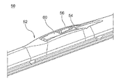
図9および図10は、このようなワイパーブレード50の構成を示している。図9および図10において、プライマリレバー52のほぼ中央部には、クリップ54を収容する収容部56が設けられている。クリップ54は、収容部56内に設けられたクリップ支持軸58により、収容部56内の一方の側に回転可能に支持されている。
9 and 10 show the configuration of such a
そして、クリップ54を、収容部56から部分的に突出する方向に回転させることにより、アームピース(図示せず)と連結できる。また、プライマリレバー52には、アームピースをクリップ54と連結した際に、クリップ54に隣接した部位に形成される空間を塞ぐためのホルダ60が設けられている。
Then, the clip 54 can be connected to the arm piece (not shown) by rotating the clip 54 in a direction in which it partially protrudes from the
図9および図10に示したプライマリレバー52は、右ハンドル用および左ハンドル用にそれぞれ専用で設定されている。このとき、プライマリレバー52の長手方向に沿った収容部56の長さは、クリップ54およびホルダ60が右ハンドル用および左ハンドル用に対応する一方の向きにしか取り付けられないことを考慮して決定される。以下、プライマリレバーの長手方向に沿った収容部の長さを、収容部のサイズと称する。
The
また、近年、部品を共通化してコストを低減するために、収容部のサイズを大きくして、クリップを取り付ける向きを変えて収容部に配置できるようにすることで、右ハンドル用および左ハンドル用のプライマリレバーを共用化することが提案されている。 Also, in recent years, in order to standardize parts and reduce costs, the size of the accommodating part has been increased so that the clip can be attached in different directions so that it can be placed in the accommodating part for right and left handles. It has been proposed to share the primary lever of.
図11は、このようなワイパーブレード50の構成を示している。図11において、プライマリレバー52に設けられた収容部56は、図10に示した収容部56よりも大きなサイズを有している。また、収容部56は、クリップ54が支持されるクリップ支持軸58に対して、左右対称の形状を有している。これにより、クリップ54を一方の向きまたはその逆向きに取り付けることができ、1つのプライマリレバー52を左右両ハンドルに用いることができる。
FIG. 11 shows the configuration of such a
図9および図10に示したようなワイパーブレード50のプライマリレバー52において、収容部56のサイズが大きくなると、プライマリレバー52の強度を確保することが困難になるという問題がある。
In the
本発明は、上記のような課題を解決するためになされたものであり、収容部のサイズを大きくした場合であっても、強度を確保することができるプライマリレバーを提供するものである。 The present invention has been made to solve the above-mentioned problems, and provides a primary lever capable of ensuring strength even when the size of the accommodating portion is increased.
本発明は、例えば、以下の態様として実現することが可能である。
第1態様によれば、プライマリレバーであって、ワイパーアームのアームピースに装着可能なクリップを収容する収容部と、収容部内に設けられた補強手段と、を備え、プライマリレバーは、カバー部材用の材料から構成されており、収容部は、第1から第4までの側壁の内壁部によって画定され、クリップは、収容部内で回転可能にプライマリレバーに支持されており、補強手段は、クリップの回転の支障とならない位置で、第1から第4までの側壁のうちの1つの側壁の内壁部から、第1から第4までの側壁のうちの他の側壁の内壁部に向けて延在するプライマリレバーが提供される。
The present invention can be realized, for example, as the following aspects.
According to the first aspect, the primary lever includes an accommodating portion for accommodating a clip that can be attached to the arm piece of the wiper arm, and a reinforcing means provided in the accommodating portion, and the primary lever is for a cover member. The containment is defined by the inner walls of the first to fourth side walls, the clip is rotatably supported by the primary lever within the containment, and the reinforcing means is of the clip. It extends from the inner wall of one of the first to fourth side walls to the inner wall of the other side of the first to fourth side walls at a position that does not interfere with rotation. A primary lever is provided.
第2態様によれば、第1態様のプライマリレバーにおいて、収容部のアームピース側とは反対側に形成された第1の開口部を備え、補強手段は、第1の開口部の少なくとも一部を覆うように形成された第1の補強部材を有する。 According to the second aspect, the primary lever of the first aspect includes a first opening formed on the side opposite to the arm piece side of the accommodating portion, and the reinforcing means is at least a part of the first opening. It has a first reinforcing member formed so as to cover the above.
第3態様によれば、第2態様のプライマリレバーにおいて、収容部内でクリップを回転可能に支持するクリップ支持軸を備え、第1の補強部材は、第1の開口部のクリップ支持軸と対向する位置で、プライマリレバーの幅方向に第1の開口部を横切って形成される。 According to the third aspect, the primary lever of the second aspect includes a clip support shaft that rotatably supports the clip in the accommodating portion, and the first reinforcing member faces the clip support shaft of the first opening. At the position, it is formed across the first opening in the width direction of the primary lever.
第4態様によれば、第2態様または第3態様のプライマリレバーにおいて、第1から第4までの側壁のうちの1つの側壁の内壁部から、第1の補強部材に向けて延在する補助補強部材を備えている。 According to the fourth aspect, in the primary lever of the second aspect or the third aspect, the auxiliary extending from the inner wall portion of one side wall of the first to fourth side walls toward the first reinforcing member. It is equipped with a reinforcing member.
第5態様によれば、第2態様から第4態様までのいずれかのプライマリレバーにおいて、第1の補強部材は、プライマリレバーの幅方向に第1の開口部を横切って形成され、第1の補強部材は、側壁の内壁部との間に段差が形成されるように、側壁の内壁部に接合される。 According to the fifth aspect, in any of the primary levers from the second aspect to the fourth aspect, the first reinforcing member is formed across the first opening in the width direction of the primary lever, and the first aspect is formed. The reinforcing member is joined to the inner wall portion of the side wall so that a step is formed between the reinforcing member and the inner wall portion of the side wall.
第6態様によれば、第1態様から第5態様までのいずれかのプライマリレバーにおいて、補強手段は、プライマリレバーの幅方向に互いに対向する2つの側壁の内壁部間を延在する軸状の第2の補強部材を有する。 According to the sixth aspect, in any of the primary levers of the first to fifth aspects, the reinforcing means is axially extending between the inner wall portions of the two side walls facing each other in the width direction of the primary lever. It has a second reinforcing member.
第7態様によれば、第6態様のプライマリレバーにおいて、収容部内で回転可能にプライマリレバーに支持されたホルダを備え、第2の補強部材は、ホルダを支持するホルダ支持軸である。 According to the seventh aspect, the primary lever of the sixth aspect includes a holder rotatably supported by the primary lever in the accommodating portion, and the second reinforcing member is a holder support shaft that supports the holder.
第8態様によれば、第7態様のプライマリレバーにおいて、ホルダ支持軸は、収容部の長手方向一端側および他端側にそれぞれ形成される。 According to the eighth aspect, in the primary lever of the seventh aspect, the holder support shafts are formed on one end side and the other end side in the longitudinal direction of the accommodating portion, respectively.
第9態様によれば、第1態様から第6態様までのいずれかのプライマリレバーにおいて、収容部のアームピース側に形成された第2の開口部と、第2の開口部の少なくとも一部を開閉可能なホルダであって、収容部内で回転可能にプライマリレバーに支持されたホルダと、を備え、収容部は、クリップが収容可能なクリップ収容部と、クリップ収容部に隣接したクリップ非収容部とを有し、クリップ収容部とクリップ非収容部とは、プライマリレバーの長手方向に沿って配置され、第2の開口部に連通しており、ホルダは、第2の開口部のうち、クリップ非収容部上の部分を閉じる閉位置と、第2の開口部のうち、クリップ非収容部上の部分を開ける開位置との間を移動する。 According to the ninth aspect, in any of the primary levers from the first aspect to the sixth aspect, the second opening formed on the arm piece side of the accommodating portion and at least a part of the second opening are formed. A holder that can be opened and closed and is rotatably supported by a primary lever in the accommodating portion, and the accommodating portion includes a clip accommodating portion that can accommodate a clip and a clip non-accommodating portion adjacent to the clip accommodating portion. The clip accommodating portion and the clip non-accommodating portion are arranged along the longitudinal direction of the primary lever and communicate with the second opening, and the holder is a clip of the second opening. It moves between the closed position where the portion on the non-accommodating portion is closed and the open position where the portion on the clip non-accommodating portion is opened in the second opening.
第10態様によれば、第9態様のプライマリレバーにおいて、クリップは、その向きを変えて、クリップ非収容部にも配置でき、また、クリップが、クリップ非収容部に配置されたとき、ホルダは、第2の開口部のうち、クリップ収容部上の部分を閉じる閉位置と、第2の開口部のうち、クリップ収容部上の部分を開ける開位置との間を移動する。 According to the tenth aspect, in the primary lever of the ninth aspect, the clip can be turned and placed in the clip non-container, and when the clip is placed in the clip non-container, the holder , The second opening is moved between the closed position where the portion on the clip accommodating portion is closed and the open position where the portion on the clip accommodating portion is opened in the second opening.
第11態様によれば、第9態様または第10態様のプライマリレバーにおいて、クリップとホルダとが、収容部に並んで配置されている。 According to the eleventh aspect, in the primary lever of the ninth aspect or the tenth aspect, the clip and the holder are arranged side by side in the accommodating portion.
第12態様によれば、第1態様から第11態様までのいずれかのプライマリレバーにおいて、カバー部材用の材料は、樹脂製である。 According to the twelfth aspect, in any of the primary levers from the first aspect to the eleventh aspect, the material for the cover member is made of resin.
第13態様によれば、第1態様から第12態様までのいずれかのプライマリレバーと、プライマリレバーに装着されたブレードラバーアッセンブリと、を備えたワイパーブレードが提供される。 According to the thirteenth aspect, a wiper blade including any of the primary levers from the first aspect to the twelfth aspect and a blade rubber assembly mounted on the primary lever is provided.
本発明によれば、カバー部材用の材料から構成されたプライマリレバーにおいて、クリップの回転の支障とならない位置で、収容部を画定する第1から第4までの側壁のうちの1つの側壁の内壁部から、第1から第4までの側壁のうちの他の側壁の内壁部に向けて延在する補強手段を設けている。これにより、収容部のサイズを大きくした場合であっても、プライマリレバーの強度を確保することができる。 According to the present invention, in a primary lever made of a material for a cover member, the inner wall of one of the first to fourth side walls defining the accommodating portion at a position that does not interfere with the rotation of the clip. Reinforcing means extending from the portion toward the inner wall portion of the other side wall of the first to fourth side walls is provided. As a result, the strength of the primary lever can be ensured even when the size of the accommodating portion is increased.
以下、本発明によるプライマリレバーの好適な実施形態につき図1〜図8に基づいて説明するが、各図において同一、または相当する部分については、同一符号を付して説明する。 Hereinafter, preferred embodiments of the primary lever according to the present invention will be described with reference to FIGS. 1 to 8, but the same or corresponding portions in each of the drawings will be described with the same reference numerals.
ワイパーブレード10は、被払拭面(例えば、自動車のフロントガラス)を払拭するためのブレードラバーアッセンブリ(図示せず)と、このブレードラバーアッセンブリを装着し、ブレードラバーアッセンブリをワイパーアームのアームピース(図示せず)に保持可能に取り付けるためのレバーアッセンブリとしてのプライマリレバー12とを備えている。
The
レバーアッセンブリは、プライマリレバー12から構成されている。すなわち、部品点数を削減してコストの低減を図るために、ワイパーブレード10には、セカンダリレバーやヨーク等が設けられておらず、このプライマリレバー12のみからレバーアッセンブリが構成されている。プライマリレバー12は、その外観を向上させるために、カバー部材に用いられる材料(例えば、樹脂)から形成されている。
The lever assembly is composed of a
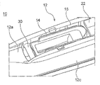
プライマリレバー12のほぼ中央部には、ワイパーアームのアームピースに装着可能なクリップ14を収容する収容部16が設けられている。クリップ14は、収容部16内に設けられたクリップ支持軸18(図2参照)により、収容部16内で回転可能に支持されている。クリップ14は、プライマリレバー12とは別体に形成されており、ワイパーブレード10をワイパーアーム(図示せず)に連結させるための結合部材である。
A
プライマリレバー12は、収容部16のうちアームピースが配置される側に、開口部20(第2の開口部)を有している(図3参照)。より具体的には、収容部16は、図3中の上方に開口部20を有している。また、プライマリレバー12は、開口部20の少なくとも一部を開閉可能なホルダ22を有している。ホルダ22は、収容部16内に設けられたホルダ支持軸24(図2参照)により、収容部16内で回転可能に支持されている。クリップ14とホルダ22とは、プライマリレバー12の長手方向に沿って、収容部16に並んで配置されている。
The
収容部16は、クリップ14が収容されるクリップ収容部26と、このクリップ収容部26に沈設したクリップ非収容部28とを有している(図2参照)。クリップ収容部26とクリップ非収容部28とは、プライマリレバー12の長手方向に沿って配置され、開口部20に連通している。ホルダ22は、開口部20のうち、クリップ非収容部28上の部分を閉じる閉位置と、開口部20のうち、クリップ非収容部28上の部分を開ける開位置との間を移動する。
The
本実施形態においては、クリップ14の向きを逆にして、収容部16の他方側にも回転可能にクリップ14を取り付けることができ、これによって、1つのプライマリレバー12を左右両ハンドルに用いることが可能となっている。すなわち、クリップ14は、その向きを変えて、クリップ非収容部28にも配置することができる。
In the present embodiment, the
このとき、ホルダ22は、収容部16内に設けられたホルダ支持軸30(図2参照)により、収容部16内で回転可能に支持される。ホルダ支持軸24およびホルダ支持軸30は、収容部16の長手方向一端側および他端側にそれぞれ形成されている。また、このとき、ホルダ22は、開口部20のうち、クリップ収容部26上の部分を閉じる閉位置と、開口部20のうち、クリップ収容部26上の部分を開ける開位置との間を移動する。
At this time, the
プライマリレバー12は、長尺状のレバー本体としての天板12aと、この天板12aの幅方向の一端から折り曲げて形成された第1の側壁12bと、天板12aの幅方向の他端から折り曲げて形成された第2の側壁12cとを有している。また、第1の側壁12bの一方側と第2の側壁12cの一方側との間には、第3の側壁12dが延在している(図2参照)。第1の側壁12bの他方側と第2の側壁12cの他方側との間には、第4の側壁12eが延在している(図2参照)。収容部16は、第1の側壁12b、第2の側壁12c、第3の側壁12dおよび第4の側壁12eの内壁部によって画定されている。
The
収容部16を画定する第1の側壁12bの部分と第2の側壁12cの部分とは、ほぼ平行に天板12aから延在しているが、収容部16を画定する第2の側壁12cの部分以外の第2の側壁12cの部分は、第1の側壁12bよりも天板12aから緩く傾斜している。
そして、プライマリレバー12が右ハンドル用に用いられた場合でも、左ハンドル用に用いられた場合でも、常に、緩やかな傾斜面を有する第2の側壁12cが、フロントガラス上で下になるように、プライマリレバー12が配置される。これにより、走行中に、傾斜面を有する第2の側壁12cにダウンフォースが働き、払拭作業が良好となる。
The portion of the
Then, regardless of whether the
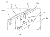
プライマリレバー12は、収容部16のうちアームピースが配置される側とは反対側に、開口部32(第1の開口部)を有している(図3参照)。より具体的には、収容部16は、図3中の下方に開口部32を有している。また、プライマリレバー12は、プライマリレバー12の幅方向に開口部32を横切って、第1の側壁12bの内壁部から、第2の側壁12cの内壁部に向けて延在する板状の橋渡し部材34(第1の補強部材)を有している(図4参照)。
The
橋渡し部材34は、開口部32のクリップ支持軸18と対向する位置で、かつクリップ14の回転の支障とならない位置に設けられている。橋渡し部材34を設けることにより、クリップ支持軸18にかかる応力を橋渡し部材34に分散させることができ、プライマリレバー12の強度を向上させることができる。すなわち、収容部16のサイズを大きくした場合であっても、クリップ支持軸18を金属部品等で補強したり、収容部16を画定する側壁を肉厚化したりすることなく、プライマリレバー12の強度を確保することができる。
The bridging
プライマリレバー12は、第3の側壁12dから橋渡し部材34に向けて延在する橋渡し部材36(補助補強部材)、および第4の側壁12eから橋渡し部材34に向けて延在する橋渡し部材38(補助補強部材)を有している(図4参照)。橋渡し部材36および橋渡し部材38を設けることにより、プライマリレバー12の強度をより向上させることができる。橋渡し部材36および橋渡し部材38は、いずれか一方のみが設けられてもよいし、橋渡し部材34のみで十分な強度が確保できる場合には、設けられなくてもよい。
The
なお、橋渡し部材は、上述したものに限定されない。橋渡し部材は、クリップ14の回転の支障とならない位置で、かつ第1の側壁12bから第4の側壁12eまでのうちの1つの内壁部から、第1の側壁12bから第4の側壁12eまでのうちの他の内壁部に向けて延在し、開口部32の少なくとも一部を覆うように形成されていれば、どこに設けられてもよい。橋渡し部材を設けることにより、収容部16のサイズを縮小したのと同等の効果が得られるため、収容部16を画定する側壁を肉厚化することなく、プライマリレバー12の強度を確保することができる。
The bridging member is not limited to the above-mentioned one. The bridging member is located at a position that does not interfere with the rotation of the
また、橋渡し部材34は、第2の側壁12cとの間に段差40が形成されるように、第2の側壁12cに接合されている(図4参照)。上述したように、プライマリレバー12は、第2の側壁12cが、フロントガラス上で常に下になるように配置される。これにより、走行中に、第2の側壁12c側から収容部16内に進入した空気を、第1の側壁12b側から容易に流出させることができ、ワイパーブレードの浮き上がりを抑制することができる。
Further, the bridging
上述したホルダ支持軸24およびホルダ支持軸30は、プライマリレバー12の互いに対向する第1の側壁12bの内壁部と第2の側壁12cの内壁部との間を延在する軸状部材であり、ホルダ22を収容部16内で回転可能に支持することができる。また、ホルダ支持軸24およびホルダ支持軸30は、クリップ14の回転の支障とならない位置に設けられている(図8参照)。
The
従来、ホルダ22を支持する部材として、ダボが用いられてきたが、ダボは、プライマリレバー12の強度に寄与しないため、収容部16のサイズが大きくなると、プライマリレバー12の強度を確保することが困難になる。そこで、ダボに代えて、第1の側壁12bの内壁部と第2の側壁12cの内壁部との間を延在する軸状部材であるホルダ支持軸24およびホルダ支持軸30を設けて、これらを第2の補強部材として用いることができる。
Conventionally, a dowel has been used as a member for supporting the
ホルダ支持軸24およびホルダ支持軸30を設けることにより、収容部16のサイズを縮小したのと同等の効果が得ることができ、プライマリレバー12の強度を向上させることができる。すなわち、収容部16のサイズを大きくした場合であっても、収容部16を画定する側壁を肉厚化することなく、プライマリレバー12の強度を確保することができる。なお、ホルダ支持軸24およびホルダ支持軸30以外の位置で、かつクリップ14の回転の支障とならない位置で、第1の側壁12bの内壁部と第2の側壁12cの内壁部との間に延在する別の軸状部材を設けてもよい。また、軸状部材に限定されず、他の形状の部材を設けてもよい。
By providing the
このプライマリレバー12によれば、ワイパーアームのアームピースに装着可能なクリップ14を収容する収容部16と、収容部16内に設けられた補強手段である橋渡し部材34、ホルダ支持軸24およびホルダ支持軸30と、を備えてる。また、プライマリレバー12は、カバー部材用の材料から構成されており、収容部16は、第1から第4までの側壁12b〜12eの内壁部によって画定され、クリップ14は、収容部16内で回転可能にプライマリレバー12に支持されており、補強手段は、クリップ14の回転の支障とならない位置で、第1から第4までの側壁12b〜12eのうちの1つの側壁の内壁部から、第1から第4までの側壁12b〜12eのうちの他の側壁の内壁部に向けて延在する。そのため、収容部16のサイズを大きくした場合であっても、プライマリレバー12の強度を確保することができる。
According to the
以上、本発明の幾つかの実施形態のみを説明したが、本発明の新規の教示や利点から実質的に外れることなく例示の実施形態に、多様な変更または改良を加えることが可能であることが当業者には容易に理解できるであろう。従って、その様な変更または改良を加えた形態も本発明の技術的範囲に含むことを意図する。また、上記実施形態を任意に組み合わせてもよい。 Although only some embodiments of the present invention have been described above, it is possible to make various changes or improvements to the illustrated embodiments without substantially departing from the novel teachings and advantages of the present invention. Will be easily understood by those skilled in the art. Therefore, it is intended that such modified or improved forms are also included in the technical scope of the present invention. Further, the above embodiments may be arbitrarily combined.
10…ワイパーブレード
12…プライマリレバー
12a…天板
12b…第1の側壁
12c…第2の側壁
12d…第3の側壁
12e…第4の側壁
14…クリップ
16…収容部
18…クリップ支持軸
20…開口部(第2の開口部)
22…ホルダ
24…ホルダ支持軸(第2の補強部材)
26…クリップ収容部
28…クリップ非収容部
30…ホルダ支持軸
32…開口部(第1の開口部)
34…橋渡し部材(第1の補強部材)
36…橋渡し部材(補助補強部材)
38…橋渡し部材(補助補強部材)
40…段差
50…ワイパーブレード
52…プライマリレバー
54…クリップ
56…収容部
58…クリップ支持軸
60…ホルダ
10 ...
22 ...
26 ...
34 ... Bridging member (first reinforcing member)
36 ... Bridging member (auxiliary reinforcing member)
38 ... Bridging member (auxiliary reinforcing member)
40 ...
Claims (13)
ワイパーアームのアームピースに装着可能なクリップを収容する収容部と、
前記収容部内に設けられた補強手段と、
前記収容部の前記アームピース側とは反対側に形成された第1の開口部と、を備え、
前記プライマリレバーは、カバー部材用の材料から構成されており、
前記収容部は、第1から第4までの側壁の内壁部によって画定され、
前記クリップは、前記収容部内で回転可能に前記プライマリレバーに支持されており、
前記補強手段は、前記クリップの回転の支障とならない位置で、前記第1から第4までの側壁のうちの1つの側壁の内壁部から、前記第1から第4までの側壁のうちの他の側壁の内壁部に向けて延在し、
前記補強手段は、前記第1の開口部の少なくとも一部を覆うように形成された第1の補強部材を有する
プライマリレバー。 It ’s the primary lever,
A housing unit that houses a clip that can be attached to the arm piece of the wiper arm,
Reinforcing means provided in the accommodating portion and
A first opening formed on the side of the accommodating portion opposite to the arm piece side is provided.
The primary lever is made of a material for a cover member.
The accommodating portion is defined by the inner wall portions of the first to fourth side walls.
The clip is rotatably supported by the primary lever within the housing.
The reinforcing means is provided from the inner wall portion of one side wall of the first to fourth side walls to the other of the first to fourth side walls at a position that does not interfere with the rotation of the clip. extend toward the inner wall portion of the side wall,
The reinforcing means is a primary lever having a first reinforcing member formed so as to cover at least a part of the first opening .
前記収容部内で前記クリップを回転可能に支持するクリップ支持軸を備え、
前記第1の補強部材は、前記第1の開口部の前記クリップ支持軸と対向する位置で、前記プライマリレバーの幅方向に前記第1の開口部を横切って形成される
プライマリレバー。 The primary lever according to claim 1 .
A clip support shaft that rotatably supports the clip in the accommodating portion is provided.
The first reinforcing member is a primary lever formed across the first opening in the width direction of the primary lever at a position facing the clip support shaft of the first opening.
前記第1から第4までの側壁のうちの1つの側壁の内壁部から、前記第1の補強部材に向けて延在する補助補強部材を備えた
プライマリレバー。 The primary lever according to claim 1 or 2 .
A primary lever provided with an auxiliary reinforcing member extending from an inner wall portion of one of the first to fourth side walls toward the first reinforcing member.
前記第1の補強部材は、前記プライマリレバーの幅方向に前記第1の開口部を横切って形成され、
前記第1の補強部材は、側壁の内壁部との間に段差が形成されるように、前記側壁の内壁部に接合される
プライマリレバー。 The primary lever according to any one of claims 1 to 3 .
The first reinforcing member is formed across the first opening in the width direction of the primary lever.
The first reinforcing member is a primary lever joined to the inner wall portion of the side wall so as to form a step with the inner wall portion of the side wall.
前記補強手段は、前記プライマリレバーの幅方向に互いに対向する2つの側壁の内壁部間を延在する軸状の第2の補強部材を有する
プライマリレバー。 The primary lever according to any one of claims 1 to 4 .
The reinforcing means is a primary lever having a second axial reinforcing member extending between the inner wall portions of two side walls facing each other in the width direction of the primary lever.
ワイパーアームのアームピースに装着可能なクリップを収容する収容部と、
前記収容部内に設けられた補強手段と、を備え、
前記プライマリレバーは、カバー部材用の材料から構成されており、
前記収容部は、第1から第4までの側壁の内壁部によって画定され、
前記クリップは、前記収容部内で回転可能に前記プライマリレバーに支持されており、
前記補強手段は、前記クリップの回転の支障とならない位置で、前記第1から第4までの側壁のうちの1つの側壁の内壁部から、前記第1から第4までの側壁のうちの他の側壁の内壁部に向けて延在し、
前記補強手段は、前記プライマリレバーの幅方向に互いに対向する2つの側壁の内壁部間を延在する軸状の第2の補強部材を有する
プライマリレバー。 It ’s the primary lever,
A housing unit that houses a clip that can be attached to the arm piece of the wiper arm,
A reinforcing means provided in the accommodating portion is provided.
The primary lever is made of a material for a cover member.
The accommodating portion is defined by the inner wall portions of the first to fourth side walls.
The clip is rotatably supported by the primary lever within the housing.
The reinforcing means is provided from the inner wall portion of one side wall of the first to fourth side walls to the other of the first to fourth side walls at a position that does not interfere with the rotation of the clip. extend toward the inner wall portion of the side wall,
The reinforcing means is a primary lever having a second axial reinforcing member extending between the inner wall portions of two side walls facing each other in the width direction of the primary lever.
前記収容部内で回転可能に前記プライマリレバーに支持されたホルダを備え、
前記第2の補強部材は、前記ホルダを支持するホルダ支持軸である
プライマリレバー。 The primary lever according to claim 5 or 6 .
A holder rotatably supported by the primary lever in the housing.
The second reinforcing member is a primary lever which is a holder support shaft for supporting the holder.
前記ホルダ支持軸は、前記収容部の長手方向一端側および他端側にそれぞれ形成される
プライマリレバー。 The primary lever according to claim 7.
The holder support shaft is a primary lever formed on one end side and the other end side in the longitudinal direction of the accommodating portion, respectively.
前記収容部の前記アームピース側に形成された第2の開口部と、
前記第2の開口部の少なくとも一部を開閉可能なホルダであって、前記収容部内で回転可能に前記プライマリレバーに支持されたホルダと、を備え、
前記収容部は、前記クリップが収容可能なクリップ収容部と、前記クリップ収容部に隣接したクリップ非収容部とを有し、前記クリップ収容部と前記クリップ非収容部とは、前記プライマリレバーの長手方向に沿って配置され、前記第2の開口部に連通しており、
前記ホルダは、前記第2の開口部のうち、前記クリップ非収容部上の部分を閉じる閉位置と、前記第2の開口部のうち、前記クリップ非収容部上の部分を開ける開位置との間を移動する
プライマリレバー。 The primary lever according to any one of claims 1 to 6.
A second opening formed on the arm piece side of the accommodating portion and
A holder that can open and close at least a part of the second opening and is rotatably supported by the primary lever in the housing portion.
The accommodating portion has a clip accommodating portion capable of accommodating the clip and a clip non-accommodating portion adjacent to the clip accommodating portion, and the clip accommodating portion and the clip non-accommodating portion are the longitudinal lengths of the primary lever. It is arranged along the direction and communicates with the second opening.
The holder has a closed position of closing the portion of the second opening on the clip non-container portion and an open position of opening the portion of the second opening on the clip non-accommodation portion. The primary lever that moves between.
前記クリップは、その向きを変えて、前記クリップ非収容部にも配置でき、また、
前記クリップが、前記クリップ非収容部に配置されたとき、前記ホルダは、前記第2の開口部のうち、前記クリップ収容部上の部分を閉じる閉位置と、前記第2の開口部のうち、前記クリップ収容部上の部分を開ける開位置との間を移動する
プライマリレバー。 The primary lever according to claim 9.
The clip can be reoriented and placed in the clip non-container as well.
When the clip is placed in the clip non-accommodating portion, the holder is in a closed position of the second opening for closing the portion on the clip accommodating portion and in the second opening. A primary lever that moves between the opening position and the opening position on the clip housing.
前記クリップと前記ホルダとが、前記収容部に並んで配置されている
プライマリレバー。 The primary lever according to claim 9 or 10.
A primary lever in which the clip and the holder are arranged side by side in the accommodating portion.
前記カバー部材用の材料は、樹脂製である
プライマリレバー。 The primary lever according to any one of claims 1 to 11.
The material for the cover member is a primary lever made of resin.
前記プライマリレバーに装着されたブレードラバーアッセンブリと、を備えた
ワイパーブレード。 The primary lever according to any one of claims 1 to 12,
A wiper blade provided with a blade rubber assembly mounted on the primary lever.
Priority Applications (2)
| Application Number | Priority Date | Filing Date | Title |
|---|---|---|---|
| JP2019073046A JP6773836B2 (en) | 2019-04-05 | 2019-04-05 | Primary lever and wiper blade |
| PCT/JP2020/015272 WO2020204156A1 (en) | 2019-04-05 | 2020-04-03 | Primary lever and wiper blade |
Applications Claiming Priority (1)
| Application Number | Priority Date | Filing Date | Title |
|---|---|---|---|
| JP2019073046A JP6773836B2 (en) | 2019-04-05 | 2019-04-05 | Primary lever and wiper blade |
Publications (2)
| Publication Number | Publication Date |
|---|---|
| JP2020169005A JP2020169005A (en) | 2020-10-15 |
| JP6773836B2 true JP6773836B2 (en) | 2020-10-21 |
Family
ID=72668072
Family Applications (1)
| Application Number | Title | Priority Date | Filing Date |
|---|---|---|---|
| JP2019073046A Active JP6773836B2 (en) | 2019-04-05 | 2019-04-05 | Primary lever and wiper blade |
Country Status (2)
| Country | Link |
|---|---|
| JP (1) | JP6773836B2 (en) |
| WO (1) | WO2020204156A1 (en) |
Family Cites Families (3)
| Publication number | Priority date | Publication date | Assignee | Title |
|---|---|---|---|---|
| JP4293465B2 (en) * | 2004-03-18 | 2009-07-08 | アスモ株式会社 | Wiper blade |
| TW200736100A (en) * | 2006-03-25 | 2007-10-01 | Shih-Hsien Huang | Connecting device for a windshield wiper having no support frame and hook type windshield wiper arm |
| US10493959B2 (en) * | 2014-07-17 | 2019-12-03 | Valeo Systèmes d'Essuyage | Streamlined flat windscreen wiper |
-
2019
- 2019-04-05 JP JP2019073046A patent/JP6773836B2/en active Active
-
2020
- 2020-04-03 WO PCT/JP2020/015272 patent/WO2020204156A1/en active Application Filing
Also Published As
| Publication number | Publication date |
|---|---|
| WO2020204156A1 (en) | 2020-10-08 |
| JP2020169005A (en) | 2020-10-15 |
Similar Documents
| Publication | Publication Date | Title |
|---|---|---|
| JP4131865B2 (en) | Wiper device | |
| JP5009933B2 (en) | Wheel loader | |
| JP2007267556A (en) | Motor with reduction gear | |
| JP6773836B2 (en) | Primary lever and wiper blade | |
| EP1584528B1 (en) | Wiper apparatus and wiper structure | |
| JP4802886B2 (en) | Cowl structure | |
| JP4149470B2 (en) | Sliding resistance applying device | |
| US10850781B2 (en) | Motor vehicle body having an air-guiding unit | |
| EP1839968A2 (en) | Motor with reduction gear | |
| JP2005297600A (en) | Wiper blade connection structure | |
| JP7131239B2 (en) | Wiper lever assembly and wiper blade | |
| JP4103578B2 (en) | Adjacent structure of rear end of hood and front fender | |
| JP5287535B2 (en) | Vehicle door handle | |
| JP2021046050A (en) | Primary lever for wiper blade | |
| JP5605899B2 (en) | Vehicle hood equipment | |
| JP7044021B2 (en) | Wiper lever assembly and wiper blade | |
| JPH054466Y2 (en) | ||
| JP2000128022A (en) | Front body structure of cab-over-engine vehicle | |
| JP4755116B2 (en) | Wiper device | |
| JP2018075964A (en) | Door hinge device for vehicle | |
| JP5662136B2 (en) | Wiper blade | |
| JP4742974B2 (en) | Body side structure | |
| JP6899185B2 (en) | Vehicle structure | |
| JP5831157B2 (en) | Vehicle door panel reinforcement structure | |
| JP3864727B2 (en) | Structure of wiper pivot part |
Legal Events
| Date | Code | Title | Description |
|---|---|---|---|
| A621 | Written request for application examination |
Free format text: JAPANESE INTERMEDIATE CODE: A621 Effective date: 20190405 |
|
| A131 | Notification of reasons for refusal |
Free format text: JAPANESE INTERMEDIATE CODE: A131 Effective date: 20200522 |
|
| A521 | Request for written amendment filed |
Free format text: JAPANESE INTERMEDIATE CODE: A523 Effective date: 20200720 |
|
| TRDD | Decision of grant or rejection written | ||
| A01 | Written decision to grant a patent or to grant a registration (utility model) |
Free format text: JAPANESE INTERMEDIATE CODE: A01 Effective date: 20200928 |
|
| A61 | First payment of annual fees (during grant procedure) |
Free format text: JAPANESE INTERMEDIATE CODE: A61 Effective date: 20201001 |
|
| R150 | Certificate of patent or registration of utility model |
Ref document number: 6773836 Country of ref document: JP Free format text: JAPANESE INTERMEDIATE CODE: R150 |
|
| R250 | Receipt of annual fees |
Free format text: JAPANESE INTERMEDIATE CODE: R250 |