JP6773673B2 - A device that creates a vacuum using the Venturi effect - Google Patents
A device that creates a vacuum using the Venturi effect Download PDFInfo
- Publication number
- JP6773673B2 JP6773673B2 JP2017547509A JP2017547509A JP6773673B2 JP 6773673 B2 JP6773673 B2 JP 6773673B2 JP 2017547509 A JP2017547509 A JP 2017547509A JP 2017547509 A JP2017547509 A JP 2017547509A JP 6773673 B2 JP6773673 B2 JP 6773673B2
- Authority
- JP
- Japan
- Prior art keywords
- passage
- power
- suction chamber
- suction
- discharge
- Prior art date
- Legal status (The legal status is an assumption and is not a legal conclusion. Google has not performed a legal analysis and makes no representation as to the accuracy of the status listed.)
- Active
Links
Images


Classifications
-
- F—MECHANICAL ENGINEERING; LIGHTING; HEATING; WEAPONS; BLASTING
- F04—POSITIVE - DISPLACEMENT MACHINES FOR LIQUIDS; PUMPS FOR LIQUIDS OR ELASTIC FLUIDS
- F04F—PUMPING OF FLUID BY DIRECT CONTACT OF ANOTHER FLUID OR BY USING INERTIA OF FLUID TO BE PUMPED; SIPHONS
- F04F5/00—Jet pumps, i.e. devices in which flow is induced by pressure drop caused by velocity of another fluid flow
- F04F5/14—Jet pumps, i.e. devices in which flow is induced by pressure drop caused by velocity of another fluid flow the inducing fluid being elastic fluid
- F04F5/16—Jet pumps, i.e. devices in which flow is induced by pressure drop caused by velocity of another fluid flow the inducing fluid being elastic fluid displacing elastic fluids
- F04F5/20—Jet pumps, i.e. devices in which flow is induced by pressure drop caused by velocity of another fluid flow the inducing fluid being elastic fluid displacing elastic fluids for evacuating
-
- B—PERFORMING OPERATIONS; TRANSPORTING
- B60—VEHICLES IN GENERAL
- B60T—VEHICLE BRAKE CONTROL SYSTEMS OR PARTS THEREOF; BRAKE CONTROL SYSTEMS OR PARTS THEREOF, IN GENERAL; ARRANGEMENT OF BRAKING ELEMENTS ON VEHICLES IN GENERAL; PORTABLE DEVICES FOR PREVENTING UNWANTED MOVEMENT OF VEHICLES; VEHICLE MODIFICATIONS TO FACILITATE COOLING OF BRAKES
- B60T13/00—Transmitting braking action from initiating means to ultimate brake actuator with power assistance or drive; Brake systems incorporating such transmitting means, e.g. air-pressure brake systems
- B60T13/10—Transmitting braking action from initiating means to ultimate brake actuator with power assistance or drive; Brake systems incorporating such transmitting means, e.g. air-pressure brake systems with fluid assistance, drive, or release
- B60T13/24—Transmitting braking action from initiating means to ultimate brake actuator with power assistance or drive; Brake systems incorporating such transmitting means, e.g. air-pressure brake systems with fluid assistance, drive, or release the fluid being gaseous
- B60T13/46—Vacuum systems
-
- B—PERFORMING OPERATIONS; TRANSPORTING
- B60—VEHICLES IN GENERAL
- B60T—VEHICLE BRAKE CONTROL SYSTEMS OR PARTS THEREOF; BRAKE CONTROL SYSTEMS OR PARTS THEREOF, IN GENERAL; ARRANGEMENT OF BRAKING ELEMENTS ON VEHICLES IN GENERAL; PORTABLE DEVICES FOR PREVENTING UNWANTED MOVEMENT OF VEHICLES; VEHICLE MODIFICATIONS TO FACILITATE COOLING OF BRAKES
- B60T17/00—Component parts, details, or accessories of power brake systems not covered by groups B60T8/00, B60T13/00 or B60T15/00, or presenting other characteristic features
- B60T17/02—Arrangements of pumps or compressors, or control devices therefor
-
- F—MECHANICAL ENGINEERING; LIGHTING; HEATING; WEAPONS; BLASTING
- F02—COMBUSTION ENGINES; HOT-GAS OR COMBUSTION-PRODUCT ENGINE PLANTS
- F02M—SUPPLYING COMBUSTION ENGINES IN GENERAL WITH COMBUSTIBLE MIXTURES OR CONSTITUENTS THEREOF
- F02M35/00—Combustion-air cleaners, air intakes, intake silencers, or induction systems specially adapted for, or arranged on, internal-combustion engines
- F02M35/10—Air intakes; Induction systems
- F02M35/10209—Fluid connections to the air intake system; their arrangement of pipes, valves or the like
- F02M35/10222—Exhaust gas recirculation [EGR]; Positive crankcase ventilation [PCV]; Additional air admission, lubricant or fuel vapour admission
-
- F—MECHANICAL ENGINEERING; LIGHTING; HEATING; WEAPONS; BLASTING
- F02—COMBUSTION ENGINES; HOT-GAS OR COMBUSTION-PRODUCT ENGINE PLANTS
- F02M—SUPPLYING COMBUSTION ENGINES IN GENERAL WITH COMBUSTIBLE MIXTURES OR CONSTITUENTS THEREOF
- F02M35/00—Combustion-air cleaners, air intakes, intake silencers, or induction systems specially adapted for, or arranged on, internal-combustion engines
- F02M35/10—Air intakes; Induction systems
- F02M35/10209—Fluid connections to the air intake system; their arrangement of pipes, valves or the like
- F02M35/10229—Fluid connections to the air intake system; their arrangement of pipes, valves or the like the intake system acting as a vacuum or overpressure source for auxiliary devices, e.g. brake systems; Vacuum chambers
-
- F—MECHANICAL ENGINEERING; LIGHTING; HEATING; WEAPONS; BLASTING
- F04—POSITIVE - DISPLACEMENT MACHINES FOR LIQUIDS; PUMPS FOR LIQUIDS OR ELASTIC FLUIDS
- F04F—PUMPING OF FLUID BY DIRECT CONTACT OF ANOTHER FLUID OR BY USING INERTIA OF FLUID TO BE PUMPED; SIPHONS
- F04F5/00—Jet pumps, i.e. devices in which flow is induced by pressure drop caused by velocity of another fluid flow
- F04F5/44—Component parts, details, or accessories not provided for in, or of interest apart from, groups F04F5/02 - F04F5/42
- F04F5/46—Arrangements of nozzles
- F04F5/464—Arrangements of nozzles with inversion of the direction of flow
-
- F—MECHANICAL ENGINEERING; LIGHTING; HEATING; WEAPONS; BLASTING
- F04—POSITIVE - DISPLACEMENT MACHINES FOR LIQUIDS; PUMPS FOR LIQUIDS OR ELASTIC FLUIDS
- F04F—PUMPING OF FLUID BY DIRECT CONTACT OF ANOTHER FLUID OR BY USING INERTIA OF FLUID TO BE PUMPED; SIPHONS
- F04F5/00—Jet pumps, i.e. devices in which flow is induced by pressure drop caused by velocity of another fluid flow
- F04F5/44—Component parts, details, or accessories not provided for in, or of interest apart from, groups F04F5/02 - F04F5/42
- F04F5/46—Arrangements of nozzles
- F04F5/466—Arrangements of nozzles with a plurality of nozzles arranged in parallel
Description
本出願は、いずれも参照により本明細書に組み込まれる、2015年3月9日に出願された米国仮出願第62/130422号、及び2015年7月17日に出願された米国仮出願第62/193633号の優先権の利益を主張するものである。 This application is incorporated herein by reference in US Provisional Application No. 62/130422, filed March 9, 2015, and US Provisional Application No. 62, filed July 17, 2015. / 193633 claims the benefit of priority.
本出願は、ベンチュリ効果を使用して真空を生成するための装置に関し、より具体的には、より大きな吸引流を穏やかな動力流量で発生させる装置に関する。 The present application relates to an apparatus for creating a vacuum using the Venturi effect, and more specifically to an apparatus for generating a larger suction flow at a gentle power flow rate.
エンジン、例えば車両エンジンは、小型化及び強化が進められており、これにより、エンジンから利用可能な真空が低減されている。この真空は、車両ブレーキブースターにより使用される場合など、多数の用途が考えられる。 Engines, such as vehicle engines, are being miniaturized and strengthened, which reduces the vacuum available from the engine. This vacuum has many possible uses, such as when used by a vehicle brake booster.
この真空不足の問題に対する一方策は、真空ポンプを設置することである。しかしながら、真空ポンプは、エンジンに対して著しいコスト及び重量のペナルティを課すものである。その電力消費により追加のオルタネーター容量が必要になる場合があり、その非効率性により燃費改善措置が妨げられ得る。 One solution to this vacuum shortage problem is to install a vacuum pump. However, vacuum pumps impose significant cost and weight penalties on the engine. Its power consumption may require additional alternator capacity, and its inefficiency can hinder fuel economy improvement measures.
別の方策は、スロットルに平行なエンジン空気流路(吸気リーク(intake leak)と呼ぶ)を作成することにより真空を発生させる吸引器である。この漏出流は、ベンチュリを通過して吸引真空を発生させる。現在利用可能な吸引器の課題は、各吸引器は、当該吸引器が発生させることのできる真空質量流量の範囲内において、当該吸引器が消費するエンジン空気量により制限されるということである。 Another strategy is an aspirator that creates a vacuum by creating an engine air flow path (called an intake leak) parallel to the throttle. This leak flow passes through the Venturi to create a suction vacuum. The challenge with currently available aspirators is that each aspirator is limited by the amount of engine air consumed by the aspirator within the range of vacuum mass flow rates that the aspirator can generate.
より大きな吸引質量流量を発生させる改善された設計が(特に動力流がブーストされた動力流である場合に)必要とされている。 An improved design is needed to generate a larger suction mass flow rate (especially if the power flow is a boosted power flow).
一態様では、吸引チャンバーと、吸引チャンバーに向かって収束するとともに吸引チャンバーと流体連通する動力通路と、吸引チャンバーから広がるとともに吸引チャンバーと流体連通する排出通路と、吸引チャンバーと流体連通する吸引通路と、を画定するハウジングを有する、ベンチュリ効果を使用して真空を生成するための装置が開示される。吸引チャンバー内では、動力通路の動力出口は、排出通路の排出入口と略一直線に配置されるとともに排出入口から離間してベンチュリギャップを画定し、吸引通路は、吸引通路から排出通路への吸引流の方向が約180°変化する位置で、吸引チャンバーに入る。 In one aspect, a suction chamber, a power passage that converges toward the suction chamber and communicates with the suction chamber, a discharge passage that extends from the suction chamber and communicates with the suction chamber, and a suction passage that communicates with the suction chamber and the fluid. Disclosed is a device for creating a vacuum using the venturi effect, having a housing defining. In the suction chamber, the power outlet of the power passage is arranged substantially in line with the discharge inlet of the discharge passage and defines a venturi gap away from the discharge inlet, and the suction passage is a suction flow from the suction passage to the discharge passage. Enter the suction chamber at a position where the direction of is changed by about 180 °.
当該装置の全態様において、装置は、以下の特徴のうち一つ又は全部を含み得る。動力通路及び排出通路はいずれも、断面積で見て双曲線関数又は放物線関数のように吸引チャンバーから広がる。吸引チャンバーは、約10mm〜約25mmの内側幅を有する。動力出口は、動力通路の内部で第1角半径を有し、排出入口は、吸引チャンバーの壁部と略同一平面上に位置するとともに、吸引チャンバーの壁部へ第2角半径で移行し得る。ここで、第2角半径は、第1角半径より大きく、動力出口の断面積は、排出入口の断面積より小さくてよい。 In all aspects of the device, the device may include one or all of the following features: Both the power passage and the discharge passage extend from the suction chamber like a hyperbolic function or a parabolic function in terms of cross-sectional area. The suction chamber has an inner width of about 10 mm to about 25 mm. The power outlet has a first angular radius inside the power passage, and the discharge inlet is located substantially coplanar with the wall of the suction chamber and can migrate to the wall of the suction chamber with a second angular radius. .. Here, the second angular radius may be larger than the first angular radius, and the cross-sectional area of the power outlet may be smaller than the cross-sectional area of the discharge inlet.
動力通路は、吸引チャンバーへ突出するとともに吸引チャンバーの一つ以上の側壁のすべてから離間して配置された吐出口で終端し得る。これにより、吐出口の外面全体の周りで吸引流をもたらす。この場合、吐出口の外面は、長手方向断面で見たときに、一つ以上の収束角度で動力通路の出口端に向かって収束する。ここで、吸引チャンバーは、吐出口の下方に、略丸みを帯びた内側底部を有する。 The power passage may be terminated at a discharge port that projects into the suction chamber and is located away from all of one or more side walls of the suction chamber. This provides a suction flow around the entire outer surface of the outlet. In this case, the outer surface of the discharge port converges toward the outlet end of the power passage at one or more convergence angles when viewed in a longitudinal cross section. Here, the suction chamber has a substantially rounded inner bottom below the discharge port.
別の態様では、吸引チャンバーと、吸引チャンバーに向かって収束するとともに吸引チャンバーと流体連通する動力通路と、吸引チャンバーから広がるとともに吸引チャンバーと流体連通する排出通路と、吸引チャンバーと流体連通する吸引通路と、を画定するハウジングを有するベンチュリ効果を使用して真空を生成するための装置が開示される。吸引チャンバー内で、動力通路の動力出口は、排出通路の排出入口と略一直線に配置されるとともに排出入口から離間してベンチュリギャップを画定し;動力通路は、吸引チャンバーへ突出するとともに吸引チャンバーの一つ以上の側壁のすべてから離間して配置された吐出口で終端し、これにより、吐出口の外面全体の周りで吸引流をもたらす。当該装置の全態様において、装置は、以下の特徴のうち一つ又は全部を含み得る。 In another embodiment, a suction chamber, a power passage that converges toward the suction chamber and communicates with the suction chamber, a discharge passage that extends from the suction chamber and communicates with the suction chamber, and a suction passage that communicates with the suction chamber and the fluid. Disclosed is a device for creating a vacuum using a venturi effect with a housing defining and. Within the suction chamber, the power outlets of the power passages are located approximately in line with the outlets of the outlets and demarcate the venturi gap away from the outlets; the power passages project into the suction chamber and of the suction chamber. It terminates at a discharge port located apart from all of one or more side walls, thereby providing a suction flow around the entire outer surface of the discharge port. In all aspects of the device, the device may include one or all of the following features:
吸引通路は、排出通路に対して平行に配置されている。吐出口の外面は、動力通路の出口端に向かって収束し、吸引チャンバーは、吐出口の下方に略丸みを帯びた内側底部を有する。吸引チャンバーは、約10mm〜約25mmの内側幅を有する。 The suction passage is arranged parallel to the discharge passage. The outer surface of the outlet converges towards the outlet end of the power passage, and the suction chamber has a substantially rounded inner bottom below the outlet. The suction chamber has an inner width of about 10 mm to about 25 mm.
動力出口は、動力通路の内部で第1角半径を有し、排出入口は、吸引チャンバーの壁部と略同一平面上に位置するとともに、吸引チャンバーの壁部へ第2角半径で移行し得る。ここで、第2角半径は、第1角半径より大きく、動力出口の断面積は、排出入口の断面積より小さくてよい。 The power outlet has a first angular radius inside the power passage, and the discharge inlet is located substantially coplanar with the wall of the suction chamber and can migrate to the wall of the suction chamber with a second angular radius. .. Here, the second angular radius may be larger than the first angular radius, and the cross-sectional area of the power outlet may be smaller than the cross-sectional area of the discharge inlet.
少なくとも排出通路は、排出通路は、排出入口を排出出口に接続する双曲面曲線により形成された内部通路であるが、動力通路及び排出通路はいずれも、断面積で見て、双曲線関数又は放物線関数のように吸引チャンバーから離れて広がり得る。 At least the discharge passage is an internal passage formed by a hyperbolic curve connecting the discharge inlet to the discharge outlet, but both the power passage and the discharge passage are hyperbolic functions or parabolic functions in terms of cross-sectional area. Can spread away from the suction chamber as in.
別の態様では、ベンチュリ効果を使用して真空を生成するための上記装置のいずれかと、動力通路に流体接続された給気圧源と、吸引通路に流体接続された、真空を必要とする装置と、排出通路に流体接続された大気圧と、を含み、当該大気圧は給気圧より低い、システムが開示される。 In another aspect, one of the above devices for creating a vacuum using the Venturi effect, a supply pressure source fluid-connected to the power passage, and a vacuum-requiring device fluid-connected to the suction passage. Disclosed is a system that includes atmospheric pressure fluidly connected to a discharge passage, the atmospheric pressure being lower than the supply pressure.
以下の詳細な説明では、本発明の一般的な原理について説明する。本発明の例が添付図面において追加的に図示される。図面では、類似の参照番号は、同一の又は機能的に類似した要素を示す。 The following detailed description describes the general principles of the present invention. Examples of the present invention are additionally illustrated in the accompanying drawings. In the drawings, similar reference numbers indicate the same or functionally similar elements.
本明細書で使用される場合、「流体(fluid)」とは、任意の液体、懸濁液、コロイド、気体、プラズマ、又はこれらの組合せを意味する。 As used herein, "fluid" means any liquid, suspension, colloid, gas, plasma, or a combination thereof.
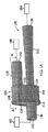
図1〜4は、ベンチュリ効果を使用して真空を生成するための装置100を別々の視点から見たものを図示する。装置100は、車両ブレーキブースト装置、ポジティブクランクケース通気システム、燃料蒸気キャニスターパージ装置、油圧弁及び/又は空気弁などの真空を必要とする装置に対して真空を提供するために、エンジン、例えば車両のエンジン(内燃機関)において使用され得る装置100は、通路104と流体連通する吸引チャンバー107(図2)を画定するハウジング106を含み、通路104は、動力ポート108の動力入口132から排出ポート112の排出出口156へ延在する。装置100は、エンジン又はエンジンに接続された構成要素に接続可能な少なくとも三つのポートを有する。これらのポートは、(1)動力ポート108;(2)任意選択でチェックバルブ(図示せず)を介して真空を必要とする装置180に接続され得る吸引ポート110;及び(3)排出ポート112を含む。これらのポート108、110、及び112の各々は、各ポートを、動力ポート108用のホースその他の図1Aに示すようなエンジン構成要素に接続するために、その外面にコネクタ特徴部117を含み得る。
FIGS. 1 to 4
図1及び図2を参照すると、ハウジング106は、動力ポート108に近接する第1端壁120、排出ポート112に近接する第2端壁122、及び第1端壁120と第2端壁122との間で延在する少なくとも一つの側壁124を含む吸引チャンバー107を画定する。横方向断面で見た吸引チャンバーは、略洋梨状、すなわち、丸みを帯びた頂部148及び丸みを帯びた底部149を有し、丸みを帯びた頂部が丸みを帯びた底部より狭い形状であってよい。図2に示すように、吸引チャンバー107は、容器118a及び蓋118bを有し、蓋118bが容器118aのリム119内に又はリム119に対して、流体密封シールを形成しながら据え付けられる、2部品構成であってよい。ここで、容器118aは、吸引ポート110及び排出ポート112を含み、蓋118bは動力ポート108を含むが、これに限定されるものではない。別の実施形態では、容器が動力ポートを含み、蓋が吸引ポート及び排出ポートを含んでもよい。
Referring to FIGS. 1 and 2, the
引き続き図2を参照すると、動力ポート108は、吸引チャンバー107に向かって収束する(converge)とともに吸引チャンバー107と流体連通する動力通路109を画定し、排出ポート112は、吸引チャンバー107から広がる(diverge)とともに吸引チャンバー107と流体連通する排出通路113を画定し、吸引ポート110は、吸引チャンバー107と流体連通する吸引通路111を画定する。これらの収束・発散セクションは、内部通路109、111、又は113の少なくとも一部の長さに沿って、徐々にかつ連続的にテーパ付けされている。動力ポート108は、動力入口132を有する入口端130及び動力出口136を有する出口端134を含む。同様に、吸引ポート110は、吸引入口142を有する入口端140及び吸引出口146を有する出口端144を含み、動力出口136及び吸引出口146はいずれも吸引チャンバー107へ出ていく。排出ポート112は、吸引チャンバー107に近接し排出入口152を有する入口端150、及び吸引チャンバー107から遠位側に位置し排出出口156を有する出口端154を含む。図2において図示されるように、吸引通路111は、吸引通路111からの吸引流の方向を排出通路113へ約180°変化させる位置で、吸引チャンバー107に入る。従って、吸引ポート110は、排出ポート112に略平行である。
Continuing with reference to FIG. 2, the
組み立てられた装置100において、特に吸引チャンバー107内において、図4に示されるように、動力通路109の出口端134、より具体的には動力出口136は、排出通路113の入口端150において、排出入口152と略一直線に配置されるとともに排出入口152から離間し、ベンチュリギャップ160を画定する。本明細書においては、ベンチュリギャップ160とは、動力出口136と排出入口152との間の直線距離VDを意味する。動力出口136は、動力通路109の内部で第1角半径162を有し、排出入口152は、吸引チャンバー107の第2端壁122及び吸引チャンバー107への移行部と略同一平面上に位置するとともに、第1角半径162より大きな第2角半径164を有する。これらの角半径162、164は、曲率が流れの方向に影響を与えるだけでなく、製造不良(バリとして知られる)を高流速領域から離れたところに配置するのに役立つので、有利である。
In the assembled
図2〜図4を参照すると、動力通路109は、吸引チャンバー107へ突出する吐出口170で終端しており、図4に示された吸引チャンバー107の内部幅WIは、約10mm〜約25mm、より好ましくは約15mm〜約20mmである。吐出口170は、吸引チャンバー107の一つ以上の側壁124のすべてから離間して配置され、これにより、吐出口170の外面172全体の周りで吸引流をもたらす。外面172は、略円錐台形であり、第1収束角度θ1(図3に示す)で動力通路109の出口端134に向かって収束する。外面172は、第1端壁120よりも出口端134に近接した面取り部174へ移行し得る。面取り部174は、第1収束角度θ1より大きな第2収束角度θ2を有する。図3に示されるように、面取り部174は、略円形の円錐台形状外面172から、より丸みを帯びた略長方形又は略楕円錐台形の形状に変化する。吐出口170の下方の吸引チャンバー107の底部は、略丸みを帯びた内側底部を有し得る。外面172及び/又は面取り部174、並びに吸引チャンバー107の内側底部の形状は、吸引流を排出入口152の方へ向けるとともに流れの擾乱/干渉を最小にするのに都合が良い。
With reference to FIGS. 2-4, the
吐出口170の壁部厚さTは、装置100の構成に従って選択された材料に応じて、約0.5mm〜約5mmでもよく、約0.5〜約3mmでもよく、約1.0mm〜約2.0mmでもよい。
The wall thickness T of the
図4において最も良く示されるように、動力出口136の断面積は、排出入口152の断面積より小さい。この差をオフセットと称する。断面積のオフセットは、装置100が組み込まれるシステムの各パラメータに応じて変わり得る。一実施形態では、オフセットは、約0.1mm〜約2.5mmの範囲、より好ましくは約0.3mm〜約1.5mmの範囲であってよい。別の実施形態では、オフセットは、約0.5mm〜約1.2mmの範囲、より好ましくは約0.7mm〜約1.0mmの範囲であってよい。
As best shown in FIG. 4, the cross-sectional area of the
装置100が車両エンジンにおいて使用するためのものである場合、車両製造業者は、通常、装置100をエンジン又はその各構成要素に接続するのに利用可能な管類/ホースのサイズに基づき、動力ポート108及び排出ポート112の両方のサイズを選択する。加えて、車両製造業者は、通常、当該システムにおいて使用するにあたり利用可能な最大動力流量を選択し、この最大動力流量が、動力出口端134において画定された内部開口、すなわち動力出口136の面積を決定する。これらの制約の範囲内で作動すると、本開示に係る装置100は、エンジンのブースト条件下で穏やかな動力流量で高吸引流量を実現したいという妥協性を著しく低減する。この妥協性低減は、吸引ポート110の向きの構成の変更、内部幅及び形状を含む吸引チャンバー107の構成の変更、動力ポート108の吐出口の構成の変更、動力出口と排出入口とのオフセットの変更、動力出口及び/又は排出入口に対する角半径の追加、及びベンチュリギャップVDの変更を伴う。
When the
稼働中、装置100、特に吸引ポート110は、真空を必要とする装置に接続され(図1参照)、装置100は、流体(通常は空気)がおよそ装置の長さにわたって延在する通路104、及び吸引チャンバー107内でそれにより画定されるベンチュリギャップ160(図4に示される)を通って流れることにより、当該装置に対して真空を形成する。一実施形態では、動力ポート108は、動力通路の流体連通のために給気圧源182に接続され、排出通路は、排出通路の流体連通のために、給気圧より低い大気圧184に接続される。このような一実施形態では、装置100は「イジェクター」と称されてもよい。別の実施形態では、動力ポート108が大気圧に接続されてもよく、排出ポート大気圧より低い圧力源に接続されてもよい。このような一実施形態では、装置100は「アスピレーター」と称されてもよい。流体(例えば空気)が動力ポートから排出ポートへ流れることにより、流体が動力通路の下流側へ引き込まれる。動力通路は、本明細書で説明されたように、直線コーンや双曲線プロファイル、放物線プロファイルであってよい。面積が減少すると、空気の速度が増加する。これが取り囲まれた空間であるので、流体力学の法則により、流体速度が増加すると静圧は減少しなければならない。収束する動力通路の最小断面積の部分は、ベンチュリギャップに当接する。空気が排出ポートへ進み続けると、空気は、排出入口及び直線コーン、双曲線プロファイル、又は放物線プロファイルの収束排出通路を通って進む。任意選択として、排出通路は、排出出口に行き着くまで直線コーン、双曲線プロファイルコーン、又は放物線プロファイルコーンの形状を保ってもよく、排出出口に到達する前に単純な円筒状の通路又はテーパ通路に移行してもよい。
During operation, the
吸引ポート110からベンチュリギャップ160への空気の流量を増加させるという要望の下、第1動力通路109の内側寸法全体を大きくすることなく排出入口152の周長を増加させることにより、ベンチュリギャップの領域が増大される。特に、動力出口136及び排出入口152は、2014年6月3日に出願された共有の米国特許出願第14/294、727号明細書において説明されるように、円形断面を有する通路と同じ面積の非円形形状は周長対面積の比率が増加するので、非円形である。それぞれ周長及び断面積を有する非円形形状が無限に考えられる。こうした非円形形状は、多角形、直線セグメントで互いに接続された非円形の曲線、またフラクタル曲線も含む。コストを最小化するために、曲線は、より単純で製造及び検査が容易であり、望ましい周長を有するものである。特に、動力通路及び排出通路の内部断面が楕円形状又は多角形状である実施形態は、上述の共有の特許出願において説明されている。この周長の増加は、本明細書において開示された動力出口の第1角半径及び排出入口の第2角半径によりさらに促進されるが、再度、ベンチュリギャップと吸引ポートとが交わる面積が増加するという利点をもたらし、これにより吸引流が増加する。
In the desire to increase the flow rate of air from the
このため、図2に示されるように、動力通路109及び排出通路113はいずれも、断面積で見て、双曲線関数又は放物線関数のように吸引チャンバー107へ収束する。動力入口132及び排出出口156は、同じ形状であっても異なる形状であってもよく、略長方形であっても、略楕円形であっても、略円形であってもよい。図1及び図2では、動力入口132及び排出出口156は円形に描かれているが、動力出口136及び排出入口152、すなわち各開口部の内部形状は、長方形又は楕円形である。その他の多角形形状とすることもでき、当該装置は、長方形又は楕円形の内部形状に限定して解釈されるべきではない。
Therefore, as shown in FIG. 2, both the
動力通路109及び/又は排出通路の内部は、略同じ形状を有するように構築され得る。例えば、上記で特定された共同出願の図7において図示された形状は、面積A1を有する円形の開口部として動力入口端130で始まり、双曲線関数のように、動力出口136においてA1より大きな面積A2を有する楕円形の開口部へと徐々に連続的に移行する。動力入口端130における円形の開口部は、双曲線又は放物線により長方形の形状の動力出口136に接続され、動力出口136における各流線が互いに平行になるという利点をもたらす。
The interior of the
吸引ポート110により画定される吸引通路111は、図1に示されるように、一定の寸法を有する略円筒状通路である。
The
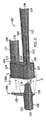
次いで、図5〜図7を参照すると、ベンチュリ効果を使用して真空を生成するための装置の別の実施形態が、一般に参照符号200で示されている。装置200は、装置100と同様に、車両ブレーキブースト装置、ポジティブクランクケース通気システム、燃料蒸気キャニスターパージ装置、油圧弁及び/又は空気弁などの装置に対して真空を提供するために、エンジン、例えば車両のエンジンにおいて使用され得る。装置200は、通路204と流体連通する吸引チャンバー107(図6)を画定するハウジング206を含み、エンジン又はエンジンに接続された構成要素接続可能な少なくとも三つのポートを有する。これらのポートは、(1)動力ポート108;(2)任意選択でチェックバルブ(図示せず)を介して真空を必要とする装置(図示せず)に接続され得る吸引ポート110;及び(3)排出ポート112を含む。これらのポート108、110、及び112の各々は、各ポートを、動力ポート108用のホースその他の図1Bに示すようなエンジン構成要素に接続するために、その外面にコネクタ特徴部117又は排出ポート112用の図6に示されるようなコネクタ特徴部217を含み得る。
Then, with reference to FIGS. 5-7, another embodiment of the device for creating a vacuum using the Venturi effect is generally indicated by
ハウジング206は、動力ポート108に近接する第1端壁120、排出ポート112に近接する第2端壁122、及び第1端壁120と第2端壁122との間で延在する少なくとも一つの側壁124を含む吸引チャンバー107を画定する。吸引チャンバー107は、横断面で見ると、排出ポート112への入口152の下方に、略丸みを帯びた底部149を有し得る。図6に示されるように、吸引チャンバー107は、容器118a及び蓋118bを有し、蓋118bが容器118aのリム119内に又はリム119に対して、流体密封シールを形成しながら据え付けられる、2部品構成であってよい。ここで、容器118aは、吸引ポート110及び排出ポート112を含み、蓋118bは動力ポート108を含むが、これに限定されるものではない。別の実施形態では、容器が動力ポートを含み、蓋が吸引ポート及び排出ポートを含んでもよい。
The
動力ポート108は、流体が吸引チャンバー107へ向かって流れるための動力通路109’であって吸引チャンバー107と流体連通する動力通路109’を画定する。動力通路109’は、略円筒形状の主通路210として始まり、動力入口132の下流側を二つの副通路202、204に分割する。各副通路202、204は、それぞれ別個の動力出口136a、136bへ繋がっている。動力出口136a、136bは、排出通路113の排出入口152と略一直線に配置されるとともに排出入口152から離間して、ベンチュリギャップ160を画定する。図7は、二つの副通路202、204を含む動力通路109’を画定する空隙(void)のモデルの斜視図である。この動力通路109’のための形状を画定するために、動力ポート108の一部は、動力入口132から上流方向に延在する略円筒形状の空隙(すなわち主通路210)を画定するとともに、主通路210から動力出口136a、136b及び動力出口136a、136bに近接する仕切り体212へ収束する空隙の内部形状を有することにより、二つの副通路202、204を画定する。仕切り体212は、動力通路109において二つの副通路202、204への分割を行うためのフォーク214を画定する。動力出口136a、136bは、断面視で(ハウジングにより動力出口として画定される空隙の内部断面)、図7に示されるような略長方形、楕円形、その他の多角形の断面形状であってよい。
The
仕切り体212(図16)の外壁216、218は、図8A及び図9Aに示されるプロファイルのイラストにおける内側の線228、230に対応する。図8Aにおける内側線228、230のプロファイルはそれぞれ、示されている双曲線関数などの同じ関数に従って略湾曲しているが、双曲線関数の代わりに放物線関数又は多項式関数であってもよい。図9Aにおける内側線228’、230’のプロファイルはそれぞれ、略直線である。二つの副通路202、204の外壁220、222(図6、中央長手軸Aから半径方向外側に向かって外側)は、図8A及び図9Aのプロファイルのイラストにおける外側の線224、226に対応する。両イラストにおける外側線224、226の各プロファイルは、示されている双曲線関数などの同じ関数に従って略湾曲しているが、双曲線関数の代わりに放物線関数又は多項式関数であってもよい。
The
図8A及び図8Bを図9A及び図9Bと比較するとわかるように、内側線228、230のプロファイルは、フォーク214の位置を変え、図8B及び図9Bのカラーのコンピュータ流体動力学モデルからわかるように、フォーク214の位置は、動力出口136a、136bからの流れの角度だけではなく、吸引流の量にも影響を及ぼす。図9Bにおける赤色の量の増加は、仕切り体212が直線状の外形の外壁216、218を有する場合の吸引流が双曲線状の外形の外壁の場合の図8Bより大きいことを示している。
As can be seen by comparing FIGS. 8A and 8B with FIGS. 9A and 9B, the profiles of
さらに図5を参照すると、吸引ポート110は、吸引チャンバー107と流体連通する吸引通路を画定する。吸引ポート110は、図2に概略的に図示されるように、吸引入口142を有する入口端140及び吸引出口を有する出口端を含み、動力出口136及び吸引出口はいずれも吸引チャンバー107へ出ていく。しかしながら、装置200では、吸引ポート110は、図5からわかるように、吸引通路から排出通路113への吸引流の方向が約90°変化する位置で吸引チャンバー107へ入る。従って、吸引ポート110は、排出ポート112に対して略垂直な向きであり、図2に示されるように一定の寸法を有する略円筒状の通路であってもよく、吸引チャンバー107に向かって収束する長さ方向に沿って、錐体のように又は双曲線関数若しくは放物線関数に従って、徐々に連続的にテーパ付けされたものであってもよい。別の実施形態では、吸引ポート110は、装置100について図示されるように、吸引通路111から排出通路113(排出ポート112に対して略平行)への吸引流の方向が約180°変化する位置で吸引チャンバー107に入ってもよい。
Further referring to FIG. 5, the
図5及び図6を参照すると、排出ポート112は、吸引チャンバー107から広がるとともに吸引チャンバー107と流体連通する排出通路113を画定する。排出ポート112は、吸引チャンバー107内で排出入口152を有する入口端150、及び吸引チャンバー107から遠位側に位置し排出出口156を有する出口端154を含む。排出通路113は、吸引チャンバー107へ突出する吐出口170で終端しており、吸引チャンバー107の内部幅WIは、約10mm〜約25mm、より好ましくは約15mm〜約20mmである。吐出口170は、吸引チャンバー107の一つ以上の側壁124のすべてから離間して配置され、これにより、吐出口170の外面172全体の周りで吸引流をもたらす。外面172は、略円錐台形であり、排出通路113の入口端150に向かって収束する。外面172は、第2端壁122よりも入口端150に近接した面取り部(図示せず)へ移行し得る。外面172及び/又は面取り部、並びに吸引チャンバー107の略丸みを帯びた内側底部の形状は、吸引流を排出入口152の方へ向けるとともに流れの擾乱/干渉を最小にするのに都合が良い。吐出口170の壁部厚さは、装置100の構成に従って選択された材料に応じて、約0.5mm〜約5mmでもよく、約0.5〜約3mmでもよく、約1.0mm〜約2.0mmでもよい。
With reference to FIGS. 5 and 6, the
また、図6において最も良く示されるように、動力出口136の(合計の)断面積は、排出入口152の断面積より小さい。この差をオフセットと称する。断面積のオフセットは、装置100が組み込まれるシステムの各パラメータに応じて変わり得る。一実施形態では、オフセットは、約0.1mm〜約2.5mmの範囲、より好ましくは約0.3mm〜約1.5mmの範囲であってよい。別の実施形態では、オフセットは、約0.5mm〜約1.2mmの範囲、より好ましくは約0.7mm〜約1.0mmの範囲であってよい。
Also, as best shown in FIG. 6, the (total) cross-sectional area of the
本明細書で開示された装置は、プラスチック材料その他の車両エンジンにおいて使用される適切な材料であって、温度や水分、圧力、振動、土砂、破片といったエンジンの状態及び路面状況に耐え得るものから成るものとすることができ、射出成形その他のキャスティングプロセス又は成形プロセスにより形成され得る。 The devices disclosed herein are plastic materials or other suitable materials used in vehicle engines that can withstand engine conditions and road conditions such as temperature, moisture, pressure, vibration, earth and sand, and debris. It can be formed by injection molding or other casting or molding process.
本発明は、特定の実施形態について図示及び説明がなされているが、本明細書を読んで理解した当業者であれば修正に想到することは明らかであり、本発明は、そうした全修正例を含むものである。 Although the present invention has been illustrated and described for a particular embodiment, it will be apparent to those skilled in the art who have read and understood the present specification to come up with modifications, and the present invention presents all such modifications. It includes.
100 装置
104 通路
106 ハウジング
107 吸引チャンバー
108 動力ポート
109、109’ 動力通路
110 吸引ポート
111 吸引通路
112 排出ポート
113 排出通路
117 コネクタ特徴部
118a 容器
118b 蓋
119 リム
120 第1端壁
122 第2端壁
124 側壁
130 動力入口端
132 動力入口
134 動力出口端
136、136a、136b 動力出口
140 入口端
142 吸引入口
144 出口端
146 吸引出口
148 頂部
149 底部
150 入口端
152 排出入口
154 出口端
156 排出出口
160 ベンチュリギャップ
162 第1角半径
164 第2角半径
170 吐出口
172 外面
174 面取り部
180 真空を必要とする装置
182 給気圧源
184 大気圧
200 装置
202、204 副通路
206 ハウジング
210 主通路
212 仕切り体
214 フォーク
217 コネクタ特徴部
Claims (12)
吸引チャンバーと、前記吸引チャンバーに向かって収束するとともに前記吸引チャンバーと流体連通する動力通路と、前記吸引チャンバーから広がるとともに前記吸引チャンバーと流体連通する排出通路と、前記吸引チャンバーと流体連通する吸引通路と、を画定するハウジングを備え;
前記吸引チャンバー内で、前記動力通路の動力出口は、前記排出通路の排出入口と略一直線に配置されるとともに前記排出入口から離間してベンチュリギャップを画定し;
前記排出入口は、前記吸引チャンバーの第1壁部に位置し、前記吸引通路の吸引出口は、前記吸引通路から前記排出通路への吸引流の方向が180°変化する位置で、前記吸引チャンバーの前記第1壁部に位置する、装置。 A device for creating a vacuum using the Venturi effect,
A suction chamber, a power passage that converges toward the suction chamber and communicates with the suction chamber in fluid, a discharge passage that extends from the suction chamber and communicates with the suction chamber, and a suction passage that communicates with the suction chamber in fluid. And with a housing that defines;
Within the suction chamber, the power outlet of the power passage is arranged substantially in line with the outlet of the discharge passage and is separated from the discharge inlet to define a Venturi gap;
The discharge inlet is located on the first wall portion of the suction chamber, and the suction outlet of the suction passage is at a position where the direction of the suction flow from the suction passage to the discharge passage changes by 180 °. A device located on the first wall portion.
前記排出通路と前記第1壁部との間の内部移行部分は、第1角半径で形成される、請求項1に記載の装置。 The discharge port is located on substantially the same plane as the first wall portion of the suction chamber.
The device according to claim 1, wherein the internal transition portion between the discharge passage and the first wall portion is formed with a first angular radius.
前記動力通路に流体接続された圧力源と;
前記吸引通路に流体接続された、真空を必要とする装置と;
前記排出通路に流体接続され、前記圧力源より低い圧力部と;
を備えるシステムであって、
前記圧力源は、大気圧又はターボチャージャー若しくはスーパーチャージャーのコンプレッサーからの給気圧である、システム。 With the apparatus according to claim 1;
With a pressure source fluidly connected to the power passage;
With a vacuum-requiring device fluid-connected to the suction passage;
With a pressure section that is fluidly connected to the discharge passage and is lower than the pressure source;
It is a system equipped with
The pressure source is atmospheric pressure or supply pressure from a turbocharged or supercharged compressor, a system.
Applications Claiming Priority (5)
| Application Number | Priority Date | Filing Date | Title |
|---|---|---|---|
| US201562130422P | 2015-03-09 | 2015-03-09 | |
| US62/130,422 | 2015-03-09 | ||
| US201562193633P | 2015-07-17 | 2015-07-17 | |
| US62/193,633 | 2015-07-17 | ||
| PCT/US2016/021559 WO2016145078A1 (en) | 2015-03-09 | 2016-03-09 | Devices for producing vacuum using the venturi effect |
Publications (3)
| Publication Number | Publication Date |
|---|---|
| JP2018507982A JP2018507982A (en) | 2018-03-22 |
| JP2018507982A5 JP2018507982A5 (en) | 2019-04-04 |
| JP6773673B2 true JP6773673B2 (en) | 2020-10-21 |
Family
ID=56879178
Family Applications (1)
| Application Number | Title | Priority Date | Filing Date |
|---|---|---|---|
| JP2017547509A Active JP6773673B2 (en) | 2015-03-09 | 2016-03-09 | A device that creates a vacuum using the Venturi effect |
Country Status (7)
| Country | Link |
|---|---|
| US (1) | US10443627B2 (en) |
| EP (1) | EP3268617B1 (en) |
| JP (1) | JP6773673B2 (en) |
| KR (1) | KR102498930B1 (en) |
| CN (1) | CN107429709B (en) |
| BR (1) | BR112017019125B1 (en) |
| WO (1) | WO2016145078A1 (en) |
Families Citing this family (7)
| Publication number | Priority date | Publication date | Assignee | Title |
|---|---|---|---|---|
| JP6554552B2 (en) * | 2015-04-13 | 2019-07-31 | デイコ アイピー ホールディングス, エルエルシーDayco Ip Holdings, Llc | Device for creating a vacuum using the venturi effect |
| JP7008691B2 (en) * | 2016-09-21 | 2022-01-25 | デイコ アイピー ホールディングス,エルエルシー | Valve gate in the venturi gap of the venturi device to create a vacuum |
| CN110446831B (en) * | 2017-03-23 | 2021-01-08 | Dlh鲍尔斯公司 | Fluid PCV valve assembly and system |
| IT201700056218A1 (en) * | 2017-05-24 | 2018-11-24 | Piergiacomo Ferrari | Ejector device particularly for inflatable units. |
| US11046359B2 (en) | 2017-09-25 | 2021-06-29 | Mando Corporation | Steer-by-wire system and control method thereof |
| US11408380B2 (en) * | 2020-12-24 | 2022-08-09 | Dayco Ip Holdings, Llc | Devices for producing vacuum using the Venturi effect having a hollow fletch |
| US11614098B2 (en) | 2020-12-24 | 2023-03-28 | Dayco Ip Holdings, Llc | Devices for producing vacuum using the Venturi effect having a solid fletch |
Family Cites Families (55)
| Publication number | Priority date | Publication date | Assignee | Title |
|---|---|---|---|---|
| US1071596A (en) * | 1912-03-05 | 1913-08-26 | Ernst Ritter Schikich Von Vellebit | Ejector for the smoking gases of blast-furnaces and the like. |
| US1845969A (en) | 1928-04-02 | 1932-02-16 | Trico Products Corp | Suction augmenting device |
| US2044088A (en) * | 1933-12-11 | 1936-06-16 | U S Submarine Motorship Dredge | Hydraulic material elevator |
| US2074480A (en) * | 1936-03-18 | 1937-03-23 | Ingersoll Rand Co | Thermocompressor |
| US2382391A (en) * | 1944-01-24 | 1945-08-14 | Berman Philip | Eductor |
| US2790595A (en) * | 1950-09-20 | 1957-04-30 | Metallgesellschaft Ag | Steam jet apparatus |
| US3064878A (en) * | 1958-01-03 | 1962-11-20 | Nash Engineering Co | Method and apparatus for high performance evacuation system |
| US3234932A (en) | 1960-09-19 | 1966-02-15 | Forrest M Bird | Respirator |
| US3239131A (en) | 1963-03-18 | 1966-03-08 | Nash Engineering Co | High vacuum ejector pump with automatic cut-in valve |
| US3592438A (en) | 1968-06-14 | 1971-07-13 | Tecalemit Engineering | Solenoid valves |
| US3754841A (en) | 1971-05-14 | 1973-08-28 | Bendix Corp | Vacuum intensified brake booster system |
| GB1402996A (en) | 1971-10-28 | 1975-08-13 | Plessey Co Ltd | Fuel-supply systems for gas-turbine engines |
| SE381704B (en) * | 1972-07-19 | 1975-12-15 | Cerac Inst Sa | SET AND DEVICE FOR GENERATING HIGH SPEED LIQUID RADIUM PULSES FOR ERODUCING PROCESSING |
| US4070292A (en) | 1975-08-25 | 1978-01-24 | American Water Recycling Company | Apparatus for treating sewage |
| DE2717685C3 (en) | 1977-04-21 | 1981-04-02 | Audi Nsu Auto Union Ag, 7107 Neckarsulm | Internal combustion engine for motor vehicles |
| JPS58180337U (en) * | 1982-05-26 | 1983-12-02 | 富士重工業株式会社 | Negative pressure generator for supercharged engines |
| US4499034A (en) | 1982-09-02 | 1985-02-12 | The United States Of America As Represented By The United States Department Of Energy | Vortex-augmented cooling tower-windmill combination |
| US4554786A (en) | 1982-09-16 | 1985-11-26 | Nissin Kogyo Kabushiki Kaisha | Vacuum source device for vacuum booster for vehicles |
| AU545569B2 (en) | 1982-09-16 | 1985-07-18 | Honda Giken Kogyo Kabushiki Kaisha | Vacuum source device |
| US4519423A (en) * | 1983-07-08 | 1985-05-28 | University Of Southern California | Mixing apparatus using a noncircular jet of small aspect ratio |
| US4834132A (en) | 1986-09-25 | 1989-05-30 | Nissan Motor Company, Limited | Fuel transfer apparatus |
| JP2780721B2 (en) * | 1990-02-07 | 1998-07-30 | ▲えい▼夫 望月 | Jet pump |
| US5167046A (en) * | 1990-04-09 | 1992-12-01 | Benson Ronald C | Induction vacuum |
| US5108266A (en) | 1991-05-29 | 1992-04-28 | Allied-Signal Inc. | Check valve with aspirating function |
| US5188141A (en) | 1991-12-03 | 1993-02-23 | Siemens Automotive Limited | Vacuum boost valve |
| US5291916A (en) | 1992-12-28 | 1994-03-08 | Excel Industries, Inc. | Check valve |
| DE4310761C2 (en) | 1993-04-01 | 1995-10-12 | Kayser A Gmbh & Co Kg | Jet pump |
| US5431346A (en) * | 1993-07-20 | 1995-07-11 | Sinaisky; Nickoli | Nozzle including a venturi tube creating external cavitation collapse for atomization |
| CA2213081A1 (en) | 1995-02-23 | 1996-08-29 | Ecolab Inc. | Apparatus and method for dispensing a viscous use solution |
| EP0841518B1 (en) * | 1996-11-08 | 2003-02-05 | Shrinkfast Corporation | Heat gun with high performance jet pump and quick change attachments |
| US6035881A (en) | 1997-05-15 | 2000-03-14 | Walter Alfmeier Ag Prazisions-Baugruppenelemente | Checkvalve unit |
| JP3442405B2 (en) | 1997-08-25 | 2003-09-02 | 三菱電機株式会社 | Duty drive solenoid valve |
| US6192911B1 (en) * | 1999-09-10 | 2001-02-27 | Ronald L. Barnes | Venturi injector with self-adjusting port |
| FR2788112B1 (en) * | 1998-12-30 | 2001-06-08 | Total Raffinage Distribution | TORCHERE-TYPE APPARATUS AND METHOD FOR THE COMBUSTION OF GAS |
| JP2001295800A (en) | 1999-12-08 | 2001-10-26 | Myotoku Ltd | Ejector type vacuum generator |
| US20060016477A1 (en) | 2004-07-23 | 2006-01-26 | Algis Zaparackas | Vacuum enhancing check valve |
| SE528482C2 (en) | 2005-05-25 | 2006-11-28 | Gm Global Tech Operations Inc | Brake booster system for vehicle, has valve arrangement, interposed in by-pass of flow line between intake manifold and brake booster, which moves to closing position at speed allowing pressure balance between manifold and booster |
| KR100767486B1 (en) | 2006-06-26 | 2007-10-17 | 현대자동차주식회사 | Vehicle brake vacuum intensifier |
| JP2008128150A (en) | 2006-11-23 | 2008-06-05 | Aisan Ind Co Ltd | Ejector and negative pressure supply device for brake booster using the same |
| US20110186151A1 (en) | 2010-02-04 | 2011-08-04 | Bernard Joseph Sparazynski | Check valve |
| US8925520B2 (en) | 2010-03-10 | 2015-01-06 | Ford Global Technologies, Llc | Intake system including vacuum aspirator |
| JP5538004B2 (en) | 2010-03-12 | 2014-07-02 | Ckd株式会社 | Pressure control device |
| DE102011010289A1 (en) | 2011-02-03 | 2012-08-09 | GM Global Technology Operations LLC (n. d. Gesetzen des Staates Delaware) | Crankcase breather device for a motor vehicle |
| KR101219346B1 (en) | 2011-06-09 | 2013-01-09 | 현대자동차주식회사 | Device and method for controlling hydrogen supply of fuel cell system |
| US8622715B1 (en) * | 2011-12-21 | 2014-01-07 | Compatible Components Corporation | Twin turbine asymmetrical nozzle and jet pump incorporating such nozzle |
| US9045038B2 (en) * | 2011-12-22 | 2015-06-02 | Eaton Corporation | Liquid trap with integral jet pump |
| US10337628B2 (en) | 2012-02-20 | 2019-07-02 | Nyloncraft Incorporated | High mass flow check valve aspirator |
| US9022007B2 (en) | 2012-03-09 | 2015-05-05 | Ford Global Technologies, Llc | Throttle valve system for an engine |
| US8783231B2 (en) | 2012-03-12 | 2014-07-22 | Ford Global Technologies, Llc | Venturi for vapor purge |
| US9027536B2 (en) | 2012-06-26 | 2015-05-12 | Ford Global Technologies, Llc | Crankcase ventilation and vacuum generation |
| US9239034B2 (en) | 2012-09-12 | 2016-01-19 | Ford Global Technologies, Llc | Ejector system for a vehicle |
| EP2935899B1 (en) * | 2012-12-21 | 2021-12-08 | Piab Aktiebolag | Vacuum ejector nozzle with elliptical diverging section |
| MX2015004705A (en) | 2013-01-14 | 2016-02-05 | Dayco Ip Holdings Llc | Piston actuator controlling a valve and method for operating the same. |
| US9827963B2 (en) * | 2013-06-11 | 2017-11-28 | Dayco Ip Holdings, Llc | Aspirators for producing vacuum using the Venturi effect |
| CN203394893U (en) | 2013-07-17 | 2014-01-15 | 温州金业气动科技有限公司 | Vacuum generator |
-
2016
- 2016-03-09 WO PCT/US2016/021559 patent/WO2016145078A1/en active Application Filing
- 2016-03-09 US US15/065,470 patent/US10443627B2/en active Active
- 2016-03-09 BR BR112017019125-3A patent/BR112017019125B1/en active IP Right Grant
- 2016-03-09 KR KR1020177026546A patent/KR102498930B1/en active IP Right Grant
- 2016-03-09 CN CN201680013143.3A patent/CN107429709B/en active Active
- 2016-03-09 JP JP2017547509A patent/JP6773673B2/en active Active
- 2016-03-09 EP EP16762428.7A patent/EP3268617B1/en active Active
Also Published As
| Publication number | Publication date |
|---|---|
| WO2016145078A1 (en) | 2016-09-15 |
| EP3268617A4 (en) | 2018-08-01 |
| KR20170126937A (en) | 2017-11-20 |
| EP3268617B1 (en) | 2021-01-06 |
| EP3268617A1 (en) | 2018-01-17 |
| CN107429709A (en) | 2017-12-01 |
| US10443627B2 (en) | 2019-10-15 |
| KR102498930B1 (en) | 2023-02-10 |
| BR112017019125B1 (en) | 2022-08-23 |
| CN107429709B (en) | 2019-11-08 |
| US20160265557A1 (en) | 2016-09-15 |
| JP2018507982A (en) | 2018-03-22 |
| BR112017019125A2 (en) | 2018-05-02 |
Similar Documents
| Publication | Publication Date | Title |
|---|---|---|
| JP6773673B2 (en) | A device that creates a vacuum using the Venturi effect | |
| KR102074029B1 (en) | Aspirators for producing vacuum using the venturi effect | |
| JP6655162B2 (en) | Device for generating a vacuum utilizing the Venturi effect, having a plurality of sub-passages and a drive outlet in a drive section | |
| KR102360318B1 (en) | Vacuum generator using the venturi effect | |
| JP6756699B2 (en) | Dual venturi device | |
| CN109715998A (en) | Gate valve in the venturi gap of Venturi for generating vacuum | |
| CN109311466B (en) | Bypass valve in device for generating vacuum | |
| US11408380B2 (en) | Devices for producing vacuum using the Venturi effect having a hollow fletch | |
| US20220205460A1 (en) | Devices for producing vacuum using the venturi effect having a solid fletch |
Legal Events
| Date | Code | Title | Description |
|---|---|---|---|
| A521 | Request for written amendment filed |
Free format text: JAPANESE INTERMEDIATE CODE: A523 Effective date: 20190222 |
|
| A621 | Written request for application examination |
Free format text: JAPANESE INTERMEDIATE CODE: A621 Effective date: 20190222 |
|
| A977 | Report on retrieval |
Free format text: JAPANESE INTERMEDIATE CODE: A971007 Effective date: 20200129 |
|
| A131 | Notification of reasons for refusal |
Free format text: JAPANESE INTERMEDIATE CODE: A131 Effective date: 20200203 |
|
| A521 | Request for written amendment filed |
Free format text: JAPANESE INTERMEDIATE CODE: A523 Effective date: 20200507 |
|
| A131 | Notification of reasons for refusal |
Free format text: JAPANESE INTERMEDIATE CODE: A131 Effective date: 20200608 |
|
| A521 | Request for written amendment filed |
Free format text: JAPANESE INTERMEDIATE CODE: A523 Effective date: 20200818 |
|
| TRDD | Decision of grant or rejection written | ||
| A01 | Written decision to grant a patent or to grant a registration (utility model) |
Free format text: JAPANESE INTERMEDIATE CODE: A01 Effective date: 20200907 |
|
| A61 | First payment of annual fees (during grant procedure) |
Free format text: JAPANESE INTERMEDIATE CODE: A61 Effective date: 20201001 |
|
| R150 | Certificate of patent or registration of utility model |
Ref document number: 6773673 Country of ref document: JP Free format text: JAPANESE INTERMEDIATE CODE: R150 |
|
| R250 | Receipt of annual fees |
Free format text: JAPANESE INTERMEDIATE CODE: R250 |