JP6772425B2 - Traveling tunnel lining imaging device and traveling tunnel lining imaging method - Google Patents
Traveling tunnel lining imaging device and traveling tunnel lining imaging method Download PDFInfo
- Publication number
- JP6772425B2 JP6772425B2 JP2017032864A JP2017032864A JP6772425B2 JP 6772425 B2 JP6772425 B2 JP 6772425B2 JP 2017032864 A JP2017032864 A JP 2017032864A JP 2017032864 A JP2017032864 A JP 2017032864A JP 6772425 B2 JP6772425 B2 JP 6772425B2
- Authority
- JP
- Japan
- Prior art keywords
- tunnel lining
- traveling
- image
- image acquisition
- lighting
- Prior art date
- Legal status (The legal status is an assumption and is not a legal conclusion. Google has not performed a legal analysis and makes no representation as to the accuracy of the status listed.)
- Active
Links
Images
Landscapes
- Investigating Materials By The Use Of Optical Means Adapted For Particular Applications (AREA)
- Stroboscope Apparatuses (AREA)
- Accessories Of Cameras (AREA)
- Studio Devices (AREA)
Description
本願発明は、トンネルの点検に関するものであり、より具体的には、点検のため走行しながらトンネル覆工の画像を取得する技術に関するものである。 The present invention relates to a tunnel inspection, and more specifically, to a technique for acquiring an image of a tunnel lining while traveling for inspection.
高度経済成長期に集中的に整備されてきた建設インフラストラクチャー(以下、「建設インフラ」という。)は、既に相当な老朽化が進んでいることが指摘されている。平成26年には「道路の老朽化対策の本格実施に関する提言(社会資本整備審議会)」がとりまとめられ、平成24年の笹子トンネルの例を挙げて「近い将来、橋梁の崩落など人命や社会装置に関わる致命的な事態を招くであろう」と警鐘を鳴らし、建設インフラの維持管理の重要性を強く唱えている。 It has been pointed out that the construction infrastructure (hereinafter referred to as "construction infrastructure"), which has been intensively developed during the period of high economic growth, has already deteriorated considerably. In 2014, "Proposals for full-scale implementation of measures against road deterioration (Social Infrastructure Development Council)" were compiled, and "In the near future, human life and society such as the collapse of bridges, etc." It will cause a fatal situation related to the equipment, "he warned, strongly advocating the importance of maintenance of construction infrastructure.
我が国の国土はその2/3が山地であり、したがって道路や線路などは必ずといっていいほど山地を通過する区間があり、国内の山岳トンネルの数は10,000を超えるといわれている。もちろんこの山岳トンネルも他の建設インフラの例外ではなく、やはり老朽化が進んでいる。特にトンネルの覆工コンクリート(以下、単に「トンネル覆工」という。)に生じるひび割れ、うき、はく離、はく落、漏水といった変状は、代表的な老朽化の症状として挙げることができる。 Two-thirds of Japan's land area is mountainous, so roads and railroad tracks almost always pass through mountainous areas, and the number of mountain tunnels in Japan is said to exceed 10,000. Of course, this mountain tunnel is no exception to other construction infrastructures, and it is still aging. In particular, deformations such as cracks, cracks, peeling, peeling, and water leakage that occur in tunnel lining concrete (hereinafter, simply referred to as "tunnel lining") can be cited as typical symptoms of aging.
トンネル覆工に生ずる変状は、緩み土圧や偏土圧、水圧、凍上圧といった外力に起因するものと、温度応力や乾燥収縮、アルカリ骨材反応など材料等に起因するものに大別される。外力による変状としては引張によるひび割れや、圧縮による圧ざ、せん断によるひび割れ等が挙げられ、材料等による変状としては主にひび割れが挙げられる。このうち外力による変状は、進行性があるものも少なくなく、この場合トンネル構造に影響を及ぼすおそれもある。一方、材料等による変状は、外力によるものほど進行性はないものの、天端からコンクリート片が落下すると大事故につながることを考えると、当然ながら看過することはできない。 Deformations that occur in tunnel lining are roughly classified into those caused by external forces such as loose earth pressure, unbalanced earth pressure, water pressure, and frost heaving pressure, and those caused by materials such as temperature stress, drying shrinkage, and alkaline aggregate reaction. To. Deformations due to external force include cracks due to tension, pressure due to compression, cracks due to shear, and the like, and deformations due to materials and the like mainly include cracks. Of these, deformation due to external force is often progressive, and in this case, it may affect the tunnel structure. On the other hand, although the deformation caused by materials is not as progressive as that caused by external force, it cannot be overlooked, considering that if a concrete piece falls from the top, it will lead to a serious accident.
このような背景のもと、国は道路法施行規則の一部を改正する省令を公布し、具体的な建設インフラの点検方法、主な変状の着目箇所、判定事例写真などを示した定期点検要領を策定している。特に山岳トンネルに関しては、安全で円滑な交通の確保や第三者への被害を防止することを目的として、「道路トンネル定期点検要領」が提示された。 Against this background, the national government promulgated a ministerial ordinance to partially revise the Road Law Enforcement Regulations, and regularly showed specific construction infrastructure inspection methods, points of interest for major deformations, and photographs of judgment cases. The inspection procedure is formulated. Especially for mountain tunnels, the "Road Tunnel Periodic Inspection Guidelines" were presented for the purpose of ensuring safe and smooth traffic and preventing damage to third parties.
この道路トンネル定期点検要領では、メンテナンスサイクル(点検、診断、措置、記録)を定期的に実施することがトンネルの維持管理にとって重要であるとしており、メンテナンスサイクルのうち特に定期点検についてその要領を示している。定期点検は文字どおり定められた頻度で繰り返し実施される点検であり、トンネル建設(トンネル覆工打設)後1〜2年の間に行われる初期点検の後、5年に1回の頻度で実施される。そして、初期点検ではトンネル全延長に対して近接目視と打音検査を行い、その後の定期点検ではトンネル全延長に対する近接目視と必要箇所の打音検査を行うよう定められている。つまり近接目視は、初期点検、定期点検にかかわらず常にトンネル全延長に対して実施しなければならない。 This road tunnel periodic inspection procedure states that it is important for tunnel maintenance to carry out regular maintenance cycles (inspection, diagnosis, measures, records), and the procedure is shown especially for periodic inspections in the maintenance cycle. ing. Periodic inspections are literally repeated inspections at a fixed frequency, and are carried out once every five years after the initial inspections that are carried out within 1 to 2 years after tunnel construction (tunnel lining placement). Will be done. In the initial inspection, close visual inspection and tapping sound inspection are performed on the entire tunnel extension, and in the subsequent periodic inspection, close visual inspection and tapping sound inspection are performed on the entire tunnel extension. In other words, close-up visual inspection must always be carried out for the entire length of the tunnel regardless of initial inspection or regular inspection.
近接目視は、「肉眼により部材の変状等の状態を把握し評価が行える距離まで接近して目視を行う」とされていることから、原則として人によって実施される。そのため多大な労力と時間を要するうえに、高所作業車の使用が避けられないため通行規制を伴うこともある。そこで道路トンネル定期点検要領では、「今後、調査技術者が近接目視によって行う評価と同等の評価が行えると判断できる新技術が開発された場合は、新技術の併用を妨げるものではない。」とし、人による作業を改善するような新たな点検技術を期待しており、これまでも種々の提案がなされてきた。例えば特許文献1では、トンネルを移動しながらビデオカメラ等でトンネル覆工面を撮影し、その画像からひび割れを抽出する技術について提案している。 Close-up visual inspection is carried out by a person in principle because it is said that "the state of deformation of the member is grasped by the naked eye and the visual inspection is performed close to a distance that can be evaluated". Therefore, it takes a lot of labor and time, and since the use of aerial work platforms is unavoidable, traffic restrictions may be involved. Therefore, the Road Tunnel Periodic Inspection Procedure states, "If a new technology is developed that can be judged to be able to perform an evaluation equivalent to the evaluation performed by a survey engineer by close visual inspection, it does not prevent the combined use of the new technology." We are expecting new inspection technology that will improve the work done by humans, and various proposals have been made so far. For example, Patent Document 1 proposes a technique of photographing a tunnel lining surface with a video camera or the like while moving the tunnel and extracting cracks from the image.
既述したとおり近接目視は人によって行われ、また当然ながらその記録も人の手で行われる。つまり、高所作業車などを利用しながらトンネル覆工に接近し、ひび割れを目視で検出するとともに、そのひび割れの位置や寸法等をあらかじめ用意した図面等にその場で記入していくわけである。しかしながら、検出したひび割れの位置と図面を照らし合わせる作業は想像以上に難しく、さらに人による作業であることから、検出したひび割れの位置や寸法の誤記入や記入漏れも考えられる。ひび割れの位置等の誤記入は次回の定期点検で混乱を招くこともあり、変状の進展に関する誤った判断にもつながりかねない。またひび割れの記入漏れはすなわち変状を放置することとなり対策が遅れる結果事故につながるおそれもある。 As mentioned above, close-up visual inspection is performed by a person, and of course, the recording is also performed by a person. In other words, while using an aerial work platform, etc., the tunnel lining is approached, cracks are visually detected, and the positions and dimensions of the cracks are entered on the spot in a prepared drawing or the like. .. However, the work of comparing the detected crack positions with the drawings is more difficult than expected, and since it is a manual work, it is possible that the detected crack positions and dimensions may be erroneously entered or omitted. Incorrect entry of the position of cracks may cause confusion in the next regular inspection, which may lead to erroneous judgment regarding the progress of deformation. In addition, omission of entry of cracks may lead to an accident as a result of delaying countermeasures because the deformation is left unattended.
そこで発明者らは、トンネル覆工の画像を利用して画像展開図を作成し、この画像展開図を参照しながら近接目視を行うという着想を得た。画像展開図に示されたひび割れを確認することで、検出したひび割れ位置の誤記入や記入漏れを防ぐことができるわけである。 Therefore, the inventors have come up with the idea of creating an image development drawing using the image of the tunnel lining and performing close visual inspection while referring to this image development drawing. By confirming the cracks shown in the developed image, it is possible to prevent erroneous entry or omission of the detected crack positions.
ところで、一般的なトンネル内では光量が十分ではないため、鮮明な画像を得るには照明が必要となる。また、一般車両の走行を阻害しないためには、相当の速度で移動しながら撮影していくことが望ましい。したがって通常は、特許文献1のようにビデオカメラ等で連続的に撮影するのが主流であり、そのため照明も走行中は継続的に行われていた。しかしながら、従来の手法ではそれほど鮮明にトンネル覆工の画像が取得できなかった。そして発明者らは、その大きな原因が継続的な照明(以下、「常時照明」という。)にあることを見出した。同じ照明器具でも、単発的な照明(以下、「フラッシュ照明」という。)に比べると、常時照明の方が少ない光量となるため鮮明な画像が取得できないわけである。 By the way, since the amount of light is not sufficient in a general tunnel, lighting is required to obtain a clear image. In addition, in order not to hinder the running of general vehicles, it is desirable to take pictures while moving at a considerable speed. Therefore, normally, as in Patent Document 1, continuous shooting with a video camera or the like is the mainstream, and therefore, lighting is also continuously performed during traveling. However, the conventional method could not obtain a clear image of the tunnel lining. The inventors have found that the major cause is continuous lighting (hereinafter referred to as "constant lighting"). Even with the same luminaire, a clear image cannot be obtained because the amount of light is smaller with constant lighting than with single-shot lighting (hereinafter referred to as "flash lighting").
本願発明の課題は、従来技術が抱える問題を解決することであり、すなわち従来技術よりも鮮明なトンネル覆工画像を取得することができる走行型トンネル覆工撮影装置、及び走行型トンネル覆工撮影方法を提供することである。 An object of the present invention is to solve a problem of the prior art, that is, a traveling tunnel lining imaging device capable of acquiring a clearer tunnel lining image than the prior art, and a traveling tunnel lining imaging. To provide a method.
本願発明は、フラッシュ照明を利用するとともに、トリガ信号に応じ照明と撮影を同期して行うことでトンネル覆工画像を取得するという点に着目したものであり、従来にはなかった発想に基づいてなされた発明である。 The present invention focuses on the fact that a tunnel lining image is acquired by using flash illumination and synchronizing illumination and shooting in response to a trigger signal, and is based on an idea that has not existed in the past. It is an invention made.
本願発明の走行型トンネル覆工撮影装置は、走行しながらトンネル覆工を撮影する装置であり、走行体と、照明手段(走行体に設置)、画像取得手段(走行体に設置)、制御手段を備えたものである。制御手段からトリガ信号が送られると、照明手段によってフラッシュ照明が行われるとともに、画像取得手段によってトンネル覆工表面の画像が取得される。 The traveling tunnel lining imaging device of the present invention is a device that photographs tunnel lining while traveling, and includes a traveling body, lighting means (installed on the traveling body), image acquisition means (installed on the traveling body), and control means. It is equipped with. When the trigger signal is sent from the control means, the lighting means performs flash illumination, and the image acquisition means acquires an image of the tunnel lining surface.
本願発明の走行型トンネル覆工撮影装置は、距離計(走行体に設置)をさらに備えたものとすることもできる。この場合の制御手段は、距離計で計測された距離に基づいてトリガ信号を送信する。 The traveling tunnel lining imaging device of the present invention may further include a range finder (installed on the traveling body). The control means in this case transmits a trigger signal based on the distance measured by the range finder.
本願発明の走行型トンネル覆工撮影装置は、制御手段があらかじめ設定された時間間隔でトリガ信号を送信するものとすることもできる。 In the traveling tunnel lining imaging device of the present invention, the control means may transmit a trigger signal at preset time intervals.
本願発明の走行型トンネル覆工撮影装置は、画像取得手段として近赤外線カメラを備えたものとすることもできる。この場合の照明手段は、近赤外線光を照射する。 The traveling tunnel lining imaging device of the present invention may also be provided with a near-infrared camera as an image acquisition means. The lighting means in this case irradiates near infrared light.
本願発明の走行型トンネル覆工撮影方法は、本願発明の走行型トンネル覆工撮影装置を用いてトンネル覆工を撮影する方法であり、照明工程と画像取得工程を備た方法である。照明工程では、走行体で走行しながら照明手段によってフラッシュ照明を行い、画像取得工程では、走行体で走行しながら画像取得手段によってトンネル覆工表面の画像を取得する。なお照明工程と画像取得工程は、制御手段から送信されるトリガ信号に応じ同期して行われる。この場合、近赤外線カメラによってトンネル覆工表面の画像を取得し、その画像に基づいて、トンネル覆工面全体の3次元モデルを作成するとともに画像展開図を作成することもできる。 The traveling tunnel lining photographing method of the present invention is a method of photographing a tunnel lining using the traveling tunnel lining photographing apparatus of the present invention, and is a method including a lighting step and an image acquisition step. In the lighting process, flash illumination is performed by the lighting means while traveling on the traveling body, and in the image acquisition process, an image of the tunnel lining surface is acquired by the image acquiring means while traveling on the traveling body. The lighting process and the image acquisition process are performed synchronously according to the trigger signal transmitted from the control means. In this case, an image of the tunnel lining surface can be acquired by a near-infrared camera, and a three-dimensional model of the entire tunnel lining surface can be created and an image development drawing can be created based on the image.
本願発明の走行型トンネル覆工撮影装置、及び走行型トンネル覆工撮影方法には、次のような効果がある。
(1)撮影時の照明をフラッシュ照明とするため、常時照明に比して光の量が多くなり、この結果鮮明な画像を取得することができる。
(2)鮮明な画像が取得されることから、トンネル覆工の画ひび割れを明瞭に把握することができる。
(3)鮮明な画像に基づく画像展開図が得られ、これを参照することで近接目視が効率的に実施できるうえ、誤記入や記入漏れを回避することができる。
(4)近赤外線カメラ(画像取得手段)を利用すれば、煤等で汚れたトンネル覆工のひび割れも把握することができる(発明者らは、煤けたトンネルで0.2mm幅のひび割れが取得できることを確認している)。
(5)近赤外線カメラを利用すればフラッシュ照明も不可視光となり、画像取得作業中でも対向車に影響を与えることがなく、また距離確保用のパトロール車に追尾させる必要もない。
The traveling tunnel lining imaging device and the traveling tunnel lining imaging method of the present invention have the following effects.
(1) Since the illumination at the time of shooting is flash illumination, the amount of light is larger than that of constant illumination, and as a result, a clear image can be acquired.
(2) Since a clear image is acquired, it is possible to clearly grasp the cracks in the image of the tunnel lining.
(3) An image development drawing based on a clear image can be obtained, and by referring to this, close-up visual inspection can be efficiently performed, and erroneous entry and omission of entry can be avoided.
(4) By using a near-infrared camera (image acquisition means), it is possible to grasp cracks in tunnel lining soiled with soot or the like (the inventors acquired cracks with a width of 0.2 mm in a sooted tunnel). I'm sure I can do it).
(5) If a near-infrared camera is used, the flash illumination becomes invisible light, which does not affect the oncoming vehicle even during the image acquisition work, and it is not necessary to track the patrol vehicle for securing the distance.
本願発明の走行型トンネル覆工撮影装置、及び走行型トンネル覆工撮影方法の実施形態の例を図に基づいて説明する。なお、本願発明の走行型トンネル覆工撮影装置は、本願発明の走行型トンネル覆工撮影方法に使用されるものでる。したがって、まずは走行型トンネル覆工撮影装置について説明し、その後に走行型トンネル覆工撮影方法について説明することとする。 An example of an embodiment of the traveling tunnel lining imaging device and the traveling tunnel lining imaging method of the present invention will be described with reference to the drawings. The traveling tunnel lining imaging device of the present invention is used in the traveling tunnel lining imaging method of the present invention. Therefore, the traveling tunnel lining imaging device will be described first, and then the traveling tunnel lining imaging method will be described.
1.走行型トンネル覆工撮影装置
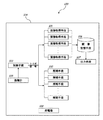
図1は、本願発明の走行型トンネル覆工撮影装置100を示すブロック図である。この図に示すように走行型トンネル覆工撮影装置100は、画像取得手段101と、照明手段102、制御手段103、走行体104を備えたものであり、さらに距離計105や、画像記憶手段106、ディスプレイやプリンタといった出力手段107、これらの機器に電気を供給する発電機108を備えたものとすることもできる。
1. 1. Traveling tunnel lining imaging device FIG. 1 is a block diagram showing a traveling tunnel
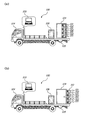
図2は、本願発明の走行型トンネル覆工撮影装置100を示す図であり、(a)は画像取得手段101と照明手段102を収納ハウス109に収納した状態を示す側面図、(a)は画像取得手段101と照明手段102を収納ハウス109から引き出した状態を示す側面図である。この図に示すように、画像取得手段101や照明手段102など走行型トンネル覆工撮影装置100を構成する各手段は、トラック等の走行体104に搭載される。例えば、画像取得手段101と照明手段102は荷台上に設置された収納ハウス109内に格納され、制御手段103は乗車室(キャビン)内に置かれる。また、発電機108は収納ハウス109と同様荷台上に設置され、距離計105は荷台下面に取り付けられ、画像記憶手段106と出力手段107は制御手段103と同様キャビン内に置かれる。
2A and 2B are views showing a traveling tunnel
(画像取得手段と照明手段)
走行型トンネル覆工撮影装置100は、移動しながらトンネル覆工の画像を取得するものであり、より詳しくは、例えば道路トンネル内を走行体104で走行しながらトンネル覆工の片側断面の画像を画像取得手段101で取得していくものである。したがって、異なる方向に向いた複数の画像取得手段101で画像を取得するのがよく、図2に示すように複数の画像取得手段101を設置するとよい。なお、図2では側方に向いた4つの画像取得手段101のみを表しているが、実際には上方を向いた複数の画像取得手段101も設置されている。
(Image acquisition means and lighting means)
The traveling tunnel
照明手段102は、画像取得手段101で撮影する際にトンネル覆工面に光を投じるものであるから、画像取得手段101と同様やはり複数設置し、さらに画像取得手段101の近傍であって同じ方向に向く姿勢で設置される。例えば図2に示すように、画像取得手段101と画像取得手段101の間に照明手段102を配置するとよい。 Since the lighting means 102 casts light on the tunnel lining surface when the image acquisition means 101 takes a picture, a plurality of the lighting means 102 are installed in the same manner as the image acquisition means 101, and further, in the vicinity of the image acquisition means 101 and in the same direction. It is installed in a facing position. For example, as shown in FIG. 2, the lighting means 102 may be arranged between the image acquisition means 101 and the image acquisition means 101.
画像取得手段101と照明手段102は、設置架台110に取り付けられる。そしてこの設置架台110は、例えばレール上をスライドしながら収納ハウス109に出し入れできるように設置される。現地までの輸送中は、図2(a)に示すように設置架台110(つまり、画像取得手段101と照明手段102)を収納ハウス109に収納することで風雨等を防護し、撮影作業中は、図2(b)に示すように設置架台110を収納ハウス109から引き出すわけである。
The image acquisition means 101 and the lighting means 102 are attached to the
画像取得手段101は、通常の可視光カメラとすることもできるし、赤外線カメラなど可視光以外のカメラを利用することもできる。特に近赤外線カメラは、トンネル覆工面に付着した煤等も透過して画像化することが出来るため、本願発明の走行型トンネル覆工撮影装置100にとっては好適である。発明者らは、近赤外線カメラで煤けたトンネル覆工面を撮影したところ、0.2mm幅のひび割れまで認識できることを確認している。なお、画像取得手段101を可視光カメラとした場合は、当然ながら照明手段102は可視光線を照射するものが採用され、画像取得手段101を近赤外線カメラとした場合は、当然ながら照明手段102は近赤外線を照射するものが採用される。
The image acquisition means 101 may be a normal visible light camera, or a camera other than visible light such as an infrared camera may be used. In particular, the near-infrared camera is suitable for the traveling tunnel
(制御手段)
制御手段103は、画像取得手段101と照明手段102に対して処理を行う命令信号(以下、「トリガ信号」という。)を送信するものである。換言すれば、画像取得手段101は制御手段103からのトリガ信号を受けることで撮影し(シャッターを押し)、照明手段102は制御手段103からのトリガ信号を受けることで近赤外線等を照射するわけである。また制御手段103は、画像取得手段101と照明手段102が同時に処理するようにトリガ信号を送信するものであり、つまりトリガ信号応じて画像取得手段101と照明手段102が同期して撮影かつ照射する。このように照明手段102による照明は、常時照明ではなく単発的なフラッシュ照明であることから、比較的(常時照明より)光量が多くなり、この結果鮮明な画像を取得することができる。
(Control means)
The control means 103 transmits a command signal (hereinafter, referred to as a “trigger signal”) for processing to the image acquisition means 101 and the lighting means 102. In other words, the image acquisition means 101 takes a picture (presses the shutter) by receiving the trigger signal from the control means 103, and the illumination means 102 irradiates near infrared rays or the like by receiving the trigger signal from the control means 103. Is. Further, the control means 103 transmits a trigger signal so that the image acquisition means 101 and the illumination means 102 process at the same time, that is, the image acquisition means 101 and the illumination means 102 simultaneously photograph and irradiate according to the trigger signal. .. As described above, since the illumination by the illumination means 102 is not constant illumination but single-shot flash illumination, the amount of light is relatively large (compared to constant illumination), and as a result, a clear image can be obtained.
制御手段103からのトリガ信号は、オペレータによる手動送信とすることもできるし、あらかじめ定めた時刻(定期的又は不定期的)に自動送信させることができる。あるいは、あらかじめ定めた距離間隔で、制御手段103にトリガ信号を自動送信させることもできる。この場合、レーザー距離計やDMI(Distance Measuring Instrument)といった距離計105を走行体104に設置し、この距離計105が測定した距離情報に応じて制御手段103にトリガ信号を自動送信させるわけである。したがって距離計105の距離情報は、リアルタイムで制御手段103に伝達される。
The trigger signal from the control means 103 may be manually transmitted by the operator, or may be automatically transmitted at a predetermined time (regular or irregular). Alternatively, the control means 103 can be made to automatically transmit the trigger signal at a predetermined distance interval. In this case, a
画像記憶手段106は、画像取得手段101が取得した画像を記憶するものであり、画像取得手段101の情報(どのカメラで撮影したか)と取得した時刻情報、あるいは取得した位置(距離計105の距離情報)などと関連付けて(紐付けて)画像を記憶するものである。また出力手段107は、画像取得手段101が取得した画像をその場で表示するディスプレイであり、あるいは画像を印刷するプリンタである。 The image storage means 106 stores the image acquired by the image acquisition means 101, and the information of the image acquisition means 101 (which camera took the picture) and the acquired time information, or the acquired position (of the distance meter 105). The image is stored in association with (linkage) with (distance information) and the like. Further, the output means 107 is a display that displays the image acquired by the image acquisition means 101 on the spot, or a printer that prints the image.
制御手段103は、専用のものとして製造することもできるが、汎用的なコンピュータ装置を利用することもできる。このコンピュータ装置は、パーソナルコンピュータ(PC)や、iPad(登録商標)といったタブレットPC、スマートフォン、あるいはPDA(PersonalData Assistance)などによって構成することができる。コンピュータ装置は、CPU等のプロセッサ、ROMやRAMといったメモリを具備しており、さらにマウスやキーボード等の入力手段やディスプレイ(表示手段600)を含むものもある。なお、一般的なPCであればマウスやキーボード等のデバイスから入力するが、タブレットPCやスマートフォンではタッチパネルを用いた操作(タップ、ピンチイン/アウト、スライド等)で入力することが多い。制御手段103としてPCを利用した場合、画像記憶手段106や出力手段107(ディスプレイ)もこのPCを利用して構築することができる。 The control means 103 can be manufactured as a dedicated one, but a general-purpose computer device can also be used. This computer device can be configured by a personal computer (PC), a tablet PC such as an iPad (registered trademark), a smartphone, a PDA (Personal Data Assistance), or the like. The computer device includes a processor such as a CPU, a memory such as a ROM and a RAM, and some includes an input means such as a mouse and a keyboard and a display (display means 600). In a general PC, input is performed from a device such as a mouse or keyboard, but in a tablet PC or smartphone, input is often performed by an operation using a touch panel (tap, pinch in / out, slide, etc.). When a PC is used as the control means 103, the image storage means 106 and the output means 107 (display) can also be constructed using this PC.
2.走行型トンネル覆工撮影方法
続いて、本願発明の走行型トンネル覆工撮影方法について図3を参照しながら説明する。なお、本願発明の走行型トンネル覆工撮影方法は、本願発明の走行型トンネル覆工撮影装置100を使用する方法であり、したがって「1.走行型トンネル覆工撮影装置」で説明した内容と重複する説明はここでは避け、走行型トンネル覆工撮影方法特有の内容のみ説明することとする。すなわち、ここに記載されていない内容は、「1.走行型トンネル覆工撮影装置」で説明したものと同様である。
2. Traveling tunnel lining imaging method Subsequently, the traveling tunnel lining imaging method of the present invention will be described with reference to FIG. The traveling tunnel lining imaging method of the present invention is a method using the traveling tunnel
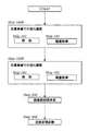
図3は、本願発明の走行型トンネル覆工撮影方法の主な工程の流れを示すフロー図である。通常トンネル覆工を撮影する場合は、この図に示すように往路(左側車線)と復路(右側車線)で2回の走行に分けて撮影される。図3を参照しながら詳しく説明する。まず、走行体104で左側車線を走行しながら一方の側面(この場合は左側壁面)と天端を撮影する(Step100A)。このとき、例えば距離計105が測定した距離情報に応じて、制御手段103がトリガ信号を自動送信し、このトリガ信号に応じて照明手段102が近赤外線等を照射するとともに(Step101)、赤外線カメラなどの画像取得手段101が撮影する(Step102)。そして左側車線側の撮影(走行)が終わると、今度は右側車線を走行しながら他方の側面(この場合は右側壁面)と天端を撮影する(Step100B)。
FIG. 3 is a flow chart showing a flow of a main process of the traveling tunnel lining photographing method of the present invention. Normally, when a tunnel lining is photographed, it is photographed in two runs on the outward route (left lane) and the return route (right lane) as shown in this figure. This will be described in detail with reference to FIG. First, while traveling in the left lane with the traveling
なお、トンネル覆工を撮影した画像は、隣接する画像と相当程度重複(ラップ)するように取得される。具体的には、延長方向(トンネル軸方向)に隣接する画像どうしは相当程度ラップし、断面方向に隣接する画像どうしも相当程度ラップしている。このようにラップしていることから、例えばSFM(Structure from Motion)といった従来から用いられている画像解析技術を使用することで、トンネル覆工面全体の3次元モデルを作成することができ、この3次元モデルをもとに画像展開図を作成することができる(Step200)。この場合、近赤外線カメラで撮影した画像をもとにSFM等の画像解析技術を用いてトンネル覆工面全体の3次元モデルを作成し、これにより画像展開図を作成することもできる。また、距離計105による距離情報が取得されていれば、この画像展開図に距離標を付与することもできる。
The image of the tunnel lining is acquired so as to overlap (wrap) with the adjacent image to a considerable extent. Specifically, the images adjacent to each other in the extension direction (tunnel axis direction) are wrapped to a considerable extent, and the images adjacent to each other in the cross-sectional direction are also wrapped to a considerable extent. Since it is wrapped in this way, it is possible to create a three-dimensional model of the entire tunnel lining surface by using a conventionally used image analysis technique such as SFM (Structure from Motion). An image development diagram can be created based on the three-dimensional model (Step 200). In this case, it is also possible to create a three-dimensional model of the entire tunnel lining surface by using an image analysis technique such as SFM based on the image taken by the near-infrared camera, and thereby create an image development drawing. Further, if the distance information is acquired by the
対象とするトンネルの画像展開図が得られると、この画像展開図を参照しながら実際に近接目視を行う(Step300)。既述のとおり、本願発明の走行型トンネル覆工撮影装置100を使用すれば比較的(常時照明より)光量が多い状態で画像を取得することができ、すなわち鮮明な画像に基づく画像展開図が得ることができる。また、道路トンネル定期点検要領で規定する「トンネル全体変状展開図」あるいは「覆工スパン別変状詳細展開図」はトンネル背面側(内空側の反対側)から見た展開図であるため誤記入が生じやすいが、本願発明による画像展開図は容易に反転できることから、反転した画像展開図(すなわち、トンネル全体変状展開図等)を参照することで近接目視が効率的に実施できるうえ、誤記入や記入漏れを回避することができる。
When an image development view of the target tunnel is obtained, a close-up visual inspection is actually performed while referring to this image development view (Step 300). As described above, if the traveling tunnel
本願発明の走行型トンネル覆工撮影装置、及び走行型トンネル覆工撮影方法は、道路トンネルのほか鉄道トンネルや、共同溝など比較的大きな埋設管にも利用することができる。本願発明によれば、供用中のトンネル覆工の劣化状況が把握でき、その劣化状況に応じた補修、補強対策が可能となり、ひいてはトンネルの長寿命化につながることを考えれば、産業上利用できるばかりでなく社会的にも大きな貢献を期待し得る発明といえる。 The traveling tunnel lining imaging device and the traveling tunnel lining imaging method of the present invention can be used not only for road tunnels but also for railway tunnels and relatively large buried pipes such as utility tunnels. According to the invention of the present application, it is possible to grasp the deterioration status of the tunnel lining in service, and it is possible to take repair and reinforcement measures according to the deterioration status, which in turn leads to an extension of the life of the tunnel. It can be said that it is an invention that can be expected to make a great contribution not only to society but also to society.
100 本願発明の走行型トンネル覆工撮影装置
101 画像取得手段
102 照明手段
103 制御手段
104 走行体
105 距離計
106 画像記憶手段
107 出力手段
108 発電機
109 収納ハウス
110 設置架台
100 Traveling tunnel
Claims (5)
走行体と、
前記走行体に設置された複数の照明手段と、
前記走行体に、異なる方向に向いて設置された複数の画像取得手段と、
前記照明手段と前記画像取得手段が取り付けられた設置架台と、
前記設置架台を収容する収納ハウスと、
制御手段と、を備え、
前記照明手段は、前記画像取得手段と前記画像取得手段の間に配置され、
前記制御手段からトリガ信号が送られると、前記照明手段によってフラッシュ照明が行われるとともに、前記画像取得手段によってトンネル覆工表面の画像を取得し、
前記設置架台は、レール上をスライドしながら前記収納ハウスに出し入れ可能である、
ことを特徴とする走行型トンネル覆工撮影装置。 In a device that photographs tunnel lining while driving
With the running body
A plurality of lighting means installed on the traveling body and
A plurality of image acquisition means installed on the traveling body in different directions,
An installation stand to which the lighting means and the image acquisition means are attached,
A storage house that houses the installation stand and
With control means,
The lighting means is arranged between the image acquisition means and the image acquisition means.
When the trigger signal is sent from the control unit, together with the flash illumination is performed by the illumination means, it acquires an image of the tunnel lining surface by the image acquiring means,
The installation stand can be taken in and out of the storage house while sliding on the rail.
A traveling tunnel lining imaging device characterized by this.
ことを特徴とする請求項1記載の走行型トンネル覆工撮影装置。 The control means transmits a trigger signal at preset time intervals.
The traveling tunnel lining photographing apparatus according to claim 1.
前記照明手段は、近赤外線光を照射する、
ことを特徴とする請求項1又は請求項2記載の走行型トンネル覆工撮影装置。 The image acquisition means is a near-infrared camera.
The lighting means irradiates near-infrared light.
The traveling tunnel lining imaging device according to claim 1 or 2 , wherein the traveling tunnel lining imaging device is characterized.
前記走行体で走行しながら、前記照明手段によってフラッシュ照明を行う照明工程と、
前記走行体で走行しながら、前記画像取得手段によってトンネル覆工表面の画像を取得する画像取得工程と、を備え、
前記照明工程と前記画像取得工程は、前記制御手段から送信されるトリガ信号に応じ同期して行われる、
ことを特徴とする走行型トンネル覆工撮影方法。 In the method of photographing a tunnel lining by using the traveling type tunnel lining photographing apparatus according to any one of claims 1 to 3 .
A lighting process in which flash lighting is performed by the lighting means while traveling on the traveling body.
An image acquisition step of acquiring an image of the tunnel lining surface by the image acquisition means while traveling on the traveling body is provided.
The lighting step and the image acquisition step are performed synchronously according to a trigger signal transmitted from the control means.
A traveling tunnel lining photography method characterized by this.
前記画像取得工程で取得した画像に基づいて、トンネル覆工面全体の3次元モデルを作成するとともに画像展開図を作成する、
ことを特徴とする請求項4記載の走行型トンネル覆工撮影方法。 In the image acquisition process, an image of the tunnel lining surface is acquired by a near-infrared camera.
Based on the image acquired in the image acquisition step, a three-dimensional model of the entire tunnel lining surface is created and an image development drawing is created.
The traveling tunnel lining photographing method according to claim 4 , wherein the traveling tunnel lining is photographed.
Priority Applications (1)
| Application Number | Priority Date | Filing Date | Title |
|---|---|---|---|
| JP2017032864A JP6772425B2 (en) | 2017-02-24 | 2017-02-24 | Traveling tunnel lining imaging device and traveling tunnel lining imaging method |
Applications Claiming Priority (1)
| Application Number | Priority Date | Filing Date | Title |
|---|---|---|---|
| JP2017032864A JP6772425B2 (en) | 2017-02-24 | 2017-02-24 | Traveling tunnel lining imaging device and traveling tunnel lining imaging method |
Publications (2)
| Publication Number | Publication Date |
|---|---|
| JP2018136285A JP2018136285A (en) | 2018-08-30 |
| JP6772425B2 true JP6772425B2 (en) | 2020-10-21 |
Family
ID=63366046
Family Applications (1)
| Application Number | Title | Priority Date | Filing Date |
|---|---|---|---|
| JP2017032864A Active JP6772425B2 (en) | 2017-02-24 | 2017-02-24 | Traveling tunnel lining imaging device and traveling tunnel lining imaging method |
Country Status (1)
| Country | Link |
|---|---|
| JP (1) | JP6772425B2 (en) |
Families Citing this family (6)
| Publication number | Priority date | Publication date | Assignee | Title |
|---|---|---|---|---|
| JP7197258B2 (en) * | 2017-08-07 | 2022-12-27 | 清水建設株式会社 | freezing method |
| EP3922700B1 (en) | 2019-03-26 | 2023-01-11 | JFE Steel Corporation | Inspection apparatus and inspection method for coke oven construction, and coke oven construction method |
| CN112946074B (en) * | 2021-01-29 | 2024-12-03 | 中国科学院武汉岩土力学研究所 | A water diversion tunnel lining structure damage detection system and method |
| CN112965055B (en) * | 2021-02-18 | 2023-01-10 | 中国矿业大学(北京) | Device and method for locating subway tunnel lining defects based on multi-channel ground penetrating radar |
| CN118175267B (en) * | 2024-03-27 | 2024-09-17 | 北京航天常兴科技发展股份有限公司 | Rail transit construction safety monitoring system |
| CN118997859B (en) * | 2024-10-24 | 2025-03-07 | 中煤科工机器人科技有限公司 | Monitoring and early warning system of mining intelligent safety command car |
Family Cites Families (7)
| Publication number | Priority date | Publication date | Assignee | Title |
|---|---|---|---|---|
| JP3420734B2 (en) * | 1999-03-12 | 2003-06-30 | 東京都下水道サービス株式会社 | Processing method of inside image of sewer |
| JP3715588B2 (en) * | 2002-06-03 | 2005-11-09 | アジア航測株式会社 | Structure wall survey equipment |
| JP3600230B2 (en) * | 2003-02-21 | 2004-12-15 | 株式会社ファースト | Architectural and civil engineering structure measurement and analysis system |
| JP5190566B2 (en) * | 2006-02-16 | 2013-04-24 | 株式会社アサノ大成基礎エンジニアリング | Tunnel inner wall inspection system |
| JP5342987B2 (en) * | 2009-12-02 | 2013-11-13 | 三井住友建設株式会社 | Concrete surface inspection equipment |
| JP6068099B2 (en) * | 2012-11-09 | 2017-01-25 | 西日本高速道路エンジニアリング四国株式会社 | Equipment for investigating the surface of road structures |
| JP6373111B2 (en) * | 2014-07-25 | 2018-08-15 | 西日本高速道路エンジニアリング四国株式会社 | Tunnel lining surface inspection system and vehicle used for tunnel lining surface inspection system |
-
2017
- 2017-02-24 JP JP2017032864A patent/JP6772425B2/en active Active
Also Published As
| Publication number | Publication date |
|---|---|
| JP2018136285A (en) | 2018-08-30 |
Similar Documents
| Publication | Publication Date | Title |
|---|---|---|
| JP6772425B2 (en) | Traveling tunnel lining imaging device and traveling tunnel lining imaging method | |
| Lee et al. | Application and validation of simple image-mosaic technology for interpreting cracks on tunnel lining | |
| US10641898B1 (en) | Structural displacement measurement using unmanned aerial vehicles equipped with lasers | |
| US10104344B2 (en) | Remote scanning and detection apparatus and method | |
| Balaguer et al. | Towards fully automated tunnel inspection: A survey and future trends | |
| Chun et al. | Development of a concrete floating and delamination detection system using infrared thermography | |
| US10866318B2 (en) | Remote scanning and detection apparatus and method | |
| JPWO2016006283A1 (en) | Structure maintenance management system and structure maintenance management method | |
| US20160350907A1 (en) | Remote scanning and detection apparatus and method | |
| CN102211590A (en) | Detecting vehicle for tunnel | |
| CN110085029A (en) | Highway cruising inspection system and method based on rail mounted crusing robot | |
| CN105735150A (en) | Movable multi-view visual bridge conventional detection method | |
| Toriumi et al. | UAV-based inspection of bridge and tunnel structures: an application review | |
| KR102172215B1 (en) | Image photographing apparatus for vertical structure | |
| CN103481910A (en) | Train part image collecting system and train part anomaly detection system | |
| Pan et al. | Enhancement of external wall decoration material for the building in safety inspection method | |
| CN107144887A (en) | A kind of track foreign body intrusion monitoring method based on machine vision | |
| Wells et al. | Use of unmanned aircraft systems for bridge inspections | |
| Winkler et al. | Measurement of local deformations in steel monostrands using digital image correlation | |
| JP5413096B2 (en) | Wire rope inspection device | |
| Ahlborn et al. | Evaluation of bridge decks using non-destructive evaluation (NDE) at near highway speeds for effective asset management. | |
| CN207516259U (en) | A kind of concrete structures underwater portion image pick-up detection device | |
| JP2019079303A (en) | Road facility inspection system, road facility inspection method, and server used therefor | |
| JP2021026353A (en) | Road surface property inspection system, road surface property inspection method, and road surface property inspection program | |
| CN103057569B (en) | A kind of rail line foreign body intrusion monitoring device and method |
Legal Events
| Date | Code | Title | Description |
|---|---|---|---|
| A521 | Request for written amendment filed |
Free format text: JAPANESE INTERMEDIATE CODE: A523 Effective date: 20170306 |
|
| A621 | Written request for application examination |
Free format text: JAPANESE INTERMEDIATE CODE: A621 Effective date: 20200110 |
|
| A871 | Explanation of circumstances concerning accelerated examination |
Free format text: JAPANESE INTERMEDIATE CODE: A871 Effective date: 20200121 |
|
| A521 | Request for written amendment filed |
Free format text: JAPANESE INTERMEDIATE CODE: A821 Effective date: 20200110 |
|
| A521 | Request for written amendment filed |
Free format text: JAPANESE INTERMEDIATE CODE: A523 Effective date: 20200302 |
|
| A975 | Report on accelerated examination |
Free format text: JAPANESE INTERMEDIATE CODE: A971005 Effective date: 20200423 |
|
| A131 | Notification of reasons for refusal |
Free format text: JAPANESE INTERMEDIATE CODE: A131 Effective date: 20200428 |
|
| A521 | Request for written amendment filed |
Free format text: JAPANESE INTERMEDIATE CODE: A523 Effective date: 20200623 |
|
| A131 | Notification of reasons for refusal |
Free format text: JAPANESE INTERMEDIATE CODE: A131 Effective date: 20200818 |
|
| A521 | Request for written amendment filed |
Free format text: JAPANESE INTERMEDIATE CODE: A523 Effective date: 20200820 |
|
| TRDD | Decision of grant or rejection written | ||
| A01 | Written decision to grant a patent or to grant a registration (utility model) |
Free format text: JAPANESE INTERMEDIATE CODE: A01 Effective date: 20200901 |
|
| A61 | First payment of annual fees (during grant procedure) |
Free format text: JAPANESE INTERMEDIATE CODE: A61 Effective date: 20200908 |
|
| R150 | Certificate of patent or registration of utility model |
Ref document number: 6772425 Country of ref document: JP Free format text: JAPANESE INTERMEDIATE CODE: R150 |
|
| R250 | Receipt of annual fees |
Free format text: JAPANESE INTERMEDIATE CODE: R250 |
|
| R250 | Receipt of annual fees |
Free format text: JAPANESE INTERMEDIATE CODE: R250 |
|
| R250 | Receipt of annual fees |
Free format text: JAPANESE INTERMEDIATE CODE: R250 |