JP6771872B2 - Image forming device - Google Patents
Image forming device Download PDFInfo
- Publication number
- JP6771872B2 JP6771872B2 JP2015175719A JP2015175719A JP6771872B2 JP 6771872 B2 JP6771872 B2 JP 6771872B2 JP 2015175719 A JP2015175719 A JP 2015175719A JP 2015175719 A JP2015175719 A JP 2015175719A JP 6771872 B2 JP6771872 B2 JP 6771872B2
- Authority
- JP
- Japan
- Prior art keywords
- paper
- recording material
- size
- image forming
- forming apparatus
- Prior art date
- Legal status (The legal status is an assumption and is not a legal conclusion. Google has not performed a legal analysis and makes no representation as to the accuracy of the status listed.)
- Active
Links
Images


Landscapes
- Control Or Security For Electrophotography (AREA)
- Manual Feeding Of Sheets (AREA)
- Sheets, Magazines, And Separation Thereof (AREA)
Description
本発明は、画像形成装置に関し、特に、給紙制御を行う画像形成装置に関する。 The present invention relates to an image forming apparatus, and more particularly to an image forming apparatus that controls paper feeding.
電子写真方式の画像形成装置は、給紙カセットや手差しトレイ上に載置された用紙を給紙して、画像形成を行う構成を備えている。従来の画像形成装置は、給紙カセットや手差しトレイ上の用紙を給紙するため、給紙ピックアップローラと、搬送センサとを有している。給紙ピックアップローラは、給紙カセットや手差しトレイ上の最上位の用紙に当接し、給紙カセットや手差しトレイ上の用紙を給紙する。搬送センサは、用紙の搬送方向の下流側に配置されたレジストレーションローラへ搬送された用紙を検出する。例えば、特許文献1では、搬送センサにより用紙が検出されてから給紙ピックアップローラの駆動が停止されるまでの時間を、操作部から入力された画像形成速度データに基づいて決定する構成が提案されている。画像形成装置では、用紙の坪量によって最適な作像及び定着速度が異なるため、用紙の種類に応じて画像形成速度が決定される。そのため、従来の構成では、給紙ピックアップローラの回転速度と画像形成速度を同じとみなして、操作部から入力された画像形成速度が速いほど、搬送センサが用紙を検出してから給紙ピックアップローラの駆動を停止するまでの時間を短くする。これにより、従来では、画像形成速度毎に給紙ピックアップローラを停止する時間を適切に制御している。
The electrophotographic image forming apparatus has a configuration in which paper placed on a paper cassette or a manual feed tray is fed to form an image. A conventional image forming apparatus has a paper feed pickup roller and a transport sensor for feeding paper on a paper feed cassette or a manual feed tray. The paper feed pickup roller comes into contact with the top-level paper on the paper feed cassette or the manual feed tray, and feeds the paper on the paper feed cassette or the manual feed tray. The transport sensor detects the paper transported to the registration rollers arranged on the downstream side in the paper transport direction. For example,
搬送される用紙の搬送方向における長さ(以下、用紙長という)に対して、給紙ピックアップローラからレジストレーションローラまでの搬送距離が長い場合、中間搬送ローラを設ける構成が知られている。この場合、中間搬送ローラの駆動伝達が給紙ピックアップローラとは異なるように構成する。そして、用紙の搬送方向における後端が給紙ピックアップローラの位置を通過すると、次の用紙が給紙されてしまうため、次の用紙が給紙される前に、給紙ピックアップローラの駆動を停止する構成となっている。以上のことから、例えば特許文献1の構成の場合、操作部から用紙長を設定することができるようにし、給紙ピックアップローラの駆動によって用紙の後端が給紙ピックアップローラの近傍まで搬送されるように駆動時間を設定する。
When the transport distance from the paper feed pickup roller to the registration roller is longer than the length in the transport direction of the paper to be transported (hereinafter referred to as the paper length), a configuration is known in which an intermediate transport roller is provided. In this case, the drive transmission of the intermediate transfer roller is configured to be different from that of the paper feed pickup roller. Then, when the rear end in the paper transport direction passes the position of the paper feed pickup roller, the next paper is fed, so the drive of the paper feed pickup roller is stopped before the next paper is fed. It is configured to do. From the above, for example, in the case of the configuration of
一方、給紙トレイから給紙された用紙の用紙長を検出するため、搬送路上の搬送センサがオンしてからオフするまでの間の時間を計測し、搬送速度と計測時間から用紙長を算出する構成が一般的に知られている。この場合、プリントジョブで設定された用紙長と、算出された実際の用紙長とを比較して、用紙長が一致するか否かを判断することで、ユーザに用紙の交換等を促すことができる。 On the other hand, in order to detect the paper length of the paper fed from the paper feed tray, the time from when the transport sensor on the transport path turns on to when it turns off is measured, and the paper length is calculated from the transport speed and the measurement time. The configuration to be used is generally known. In this case, the paper length set in the print job is compared with the calculated actual paper length to determine whether or not the paper lengths match, thereby prompting the user to replace the paper. it can.
従来技術では、用紙の後端が給紙ピックアップローラの位置を通過する前に、給紙ピックアップローラの駆動を停止しないと、次の用紙が給紙されてしまう。そのため、操作部から入力された用紙長に基づいて、用紙の後端が給紙ピックアップローラの位置を通過する前に、給紙ピックアップローラの駆動を停止させる必要がある。しかし、給紙カセットや給紙トレイ上に積載された用紙の実際の用紙長に対して、プリントジョブで設定された用紙長が長く、用紙長が一致しない場合がある。この場合、用紙の後端が給紙ピックアップローラを通過した後も給紙ピックアップローラの駆動が停止されないこととなる。このため、一度のピックアップ動作で、給紙トレイから二枚以上の用紙が連続して給紙されてしまう。そして、連続して給紙された二枚の用紙の間に紙間が形成されない場合、搬送センサが紙間ではオフ状態にならない。例えば、実際の用紙長がA4横用紙で、プリントジョブで設定された用紙長がA3縦用紙の場合、搬送センサがオンしてからオフするまでの時間がA3縦の場合のサイズと同じになる。その結果、用紙長が一致しないことを判断することができない。 In the prior art, if the drive of the paper feed pickup roller is not stopped before the rear end of the paper passes through the position of the paper feed pickup roller, the next paper will be fed. Therefore, based on the paper length input from the operation unit, it is necessary to stop the drive of the paper feed pickup roller before the rear end of the paper passes the position of the paper feed pickup roller. However, the paper length set in the print job may be longer than the actual paper length of the paper loaded on the paper cassette or the paper tray, and the paper length may not match. In this case, the drive of the paper feed pickup roller is not stopped even after the rear end of the paper has passed through the paper feed pickup roller. For this reason, two or more sheets of paper are continuously fed from the paper feed tray by one pickup operation. Then, if no paper gap is formed between the two sheets of paper fed continuously, the transport sensor does not turn off between the papers. For example, if the actual paper length is A4 landscape paper and the paper length set in the print job is A3 portrait paper, the time from when the transport sensor turns on to when it turns off is the same as the size for A3 portrait. .. As a result, it cannot be determined that the paper lengths do not match.
一方、中間搬送ローラに用紙が挟持された後、すぐに給紙ピックアップローラを駆動するモータの駆動を停止させても、給紙ピックアップローラは用紙の搬送に従動して回転する。このため、モータによる駆動が停止されている給紙ピックアップローラを回転させていることで、用紙にかかる給紙ピックアップローラの回転抵抗を、中間搬送ローラの駆動トルクで補う必要がある。そうすると、中間搬送ローラによってレジストレーションローラまで用紙を搬送する際の動作が安定しない。用紙の搬送を安定させるために、給紙ピックアップローラの駆動を停止させるタイミングは、可能な限り、用紙の後端が給紙ピックアップローラの位置を通過するよりも手前(搬送方向における上流側)近傍にすることが望ましい。 On the other hand, even if the drive of the motor that drives the paper feed pickup roller is stopped immediately after the paper is sandwiched between the intermediate transport rollers, the paper feed pickup roller rotates in accordance with the paper transport. Therefore, it is necessary to supplement the rotational resistance of the paper feed pickup roller with the drive torque of the intermediate transport roller by rotating the paper feed pickup roller whose drive by the motor is stopped. Then, the operation when the paper is conveyed to the registration roller by the intermediate transfer roller is not stable. In order to stabilize the paper transport, the timing to stop the drive of the paper feed pickup roller is as close as possible to the front (upstream side in the transport direction) of the rear end of the paper passing through the position of the paper feed pickup roller. It is desirable to.
本発明は、このような状況のもとでなされたもので、用紙の搬送を安定させつつ、実際の用紙長と設定された用紙長が一致しないことを検知できるようにすることを目的とする。 The present invention has been made under such circumstances, and an object of the present invention is to be able to detect that the actual paper length and the set paper length do not match while stabilizing the paper transport. ..
上述した課題を解決するために、本発明は、以下の構成を備える。 In order to solve the above-mentioned problems, the present invention includes the following configurations.
(1)画像形成装置であって、記録材が積載される積載部と、前記積載部に積載された記録材のサイズを設定する設定手段と、前記積載部に積載された記録材を搬送路に給紙する給紙手段と、前記給紙手段により給紙される記録材を搬送する搬送手段と、前記搬送手段により搬送される記録材の搬送方向のサイズを検知するサイズ検知手段と、前記給紙手段を駆動する駆動手段と、前記駆動手段を制御する制御手段と、を備え、前記制御手段は、前記給紙手段が記録材を給紙できない状態から給紙できる状態になった後の最初の1枚目の記録材を給紙する際の前記駆動手段を駆動する時間を、前記設定手段により設定された記録材のサイズにかかわらず、所定のサイズの記録材を給紙する際の第1時間に決定し、前記給紙手段により給紙された前記1枚目の記録材のサイズが前記サイズ検知手段により検知され、検知された前記1枚目の記録材のサイズが前記設定手段により設定されたサイズと一致することが判定された場合には、その次に記録材を給紙する際の前記駆動手段を駆動する時間を前記第1時間以上であり、且つ前記設定手段により設定された記録材のサイズに応じた異なる時間に決定することを特徴とする画像形成装置。
(2)画像形成装置であって、記録材が積載される積載部と、前記積載部に積載された記録材のサイズを設定する設定手段と、前記積載部に積載された記録材を搬送路に給紙する給紙手段と、前記給紙手段により給紙される記録材を搬送する搬送手段と、前記搬送手段により搬送される記録材の搬送方向のサイズを検知するサイズ検知手段と、前記給紙手段を制御する制御手段と、を備え、前記制御手段は、前記給紙手段が記録材を給紙できない状態から給紙できる状態になった後の最初の1枚目の記録材を前記給紙手段により搬送する距離を、前記設定手段により設定された記録材のサイズにかかわらず、前記画像形成装置で使用が許可されている記録材のサイズの中で、最も小さい記録材のサイズに応じた第1距離に決定し、前記給紙手段により給紙された前記1枚目の記録材のサイズが前記サイズ検知手段により検知され、検知された前記1枚目の記録材のサイズが前記設定手段により設定されたサイズと異なることが判定された場合には、その次に記録材を給紙する際の前記給紙手段により搬送する距離を前記第1距離に決定し、検知された前記1枚目の記録材のサイズが前記設定手段により設定されたサイズと同じであることが判定された場合には、その次に記録材を給紙する際の前記給紙手段により搬送する距離を前記設定手段により設定された記録材のサイズに基づいて決定することを特徴とする画像形成装置。
(1) An image forming apparatus, which is a loading portion on which a recording material is loaded, a setting means for setting the size of the recording material loaded on the loading portion, and a transport path for the recording material loaded on the loading portion. A paper feeding means for feeding paper, a transporting means for transporting the recording material fed by the paper feeding means, a size detecting means for detecting the size of the recording material conveyed by the transporting means in the transport direction, and the above. A drive means for driving the paper feed means and a control means for controlling the drive means are provided, and the control means is after the paper feed means has changed from a state in which the recording material cannot be fed to a state in which the recording material can be fed. When feeding a recording material of a predetermined size, the time for driving the driving means when feeding the first first recording material is set regardless of the size of the recording material set by the setting means. The size of the first recording material determined in the first hour and fed by the paper feeding means is detected by the size detecting means, and the detected size of the first recording material is the setting means. If it is determined that the size matches the size set by, the time for driving the driving means when the recording material is then fed is set to the first time or more and set by the setting means. An image forming apparatus characterized in that it is determined at different times according to the size of the recording material .
(2) An image forming apparatus, which is a loading portion on which recording material is loaded, a setting means for setting the size of the recording material loaded on the loading portion, and a transport path for recording material loaded on the loading portion. A paper feeding means for feeding paper, a transporting means for transporting the recording material fed by the paper feeding means, a size detecting means for detecting the size of the recording material conveyed by the transporting means in the transport direction, and the above. A control means for controlling the paper feeding means is provided, and the control means prepares the first recording material after the paper feeding means is in a state where the recording material cannot be fed to a state in which the recording material can be fed. The distance conveyed by the paper feeding means is set to the smallest recording material size among the recording material sizes permitted to be used by the image forming apparatus, regardless of the recording material size set by the setting means. determining a first distance in response, wherein the size of the recording material of the first sheet that has been fed is by feeding means is detected by said size detecting means, the size of the detected said first recording medium is a When it is determined that the size is different from the size set by the setting means, the distance to be conveyed by the paper feeding means when the recording material is next fed is determined as the first distance, and the detected distance is determined. When it is determined that the size of the first recording material is the same as the size set by the setting means, the distance to be conveyed by the paper feeding means when the next recording material is fed is determined. An image forming apparatus, which is determined based on the size of a recording material set by the setting means .
本発明によれば、用紙の搬送を安定させつつ、実際の用紙長と設定された用紙長が一致しないことを検知できるようにすることができる。 According to the present invention, it is possible to detect that the actual paper length and the set paper length do not match while stabilizing the paper transport.
以下、本発明を実施するための形態を、図面を参照しながら詳しく説明する。 Hereinafter, embodiments for carrying out the present invention will be described in detail with reference to the drawings.
[実施の形態]
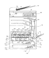
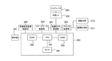
図1は、実施の形態の画像形成装置の断面図、図2は、本実施の形態の画像形成装置のブロック図である。図1、図2を用いて、基本的な構成を説明する。
[Embodiment]
FIG. 1 is a cross-sectional view of the image forming apparatus of the embodiment, and FIG. 2 is a block diagram of the image forming apparatus of the present embodiment. The basic configuration will be described with reference to FIGS. 1 and 2.
[画像形成装置の概略構成]
図2の制御部300は、図1の画像形成装置のシステム制御を行っており、CPU301、ROM302、RAM303とタイマ291を有している。CPU301は画像形成装置のシステム制御を行うCPUである。CPU301には、制御プログラムが書き込まれたROM302と、制御に用いる変数や図1のイメージセンサ233によって読み取られた画像データを保存するRAM303が、アドレスバスとデータバスにより接続されている。また、時間を計測することが可能なタイマ291がCPU301に接続されており、CPU301はタイマ291のタイムカウント値の設定やタイマ計測値の取得を行う。CPU301は、原稿給送装置制御部480を介して、原稿搬送ローラ112の駆動や、原稿有無センサ151による原稿有無検知などを行う。またCPU301は、イメージリーダ制御部280を介して、原稿圧板の開閉動作の検知や原稿圧板ガラス板55上の原稿画像、原稿給送装置制御部480によって給送された原稿画像をイメージセンサ233により読み取る。イメージセンサ233は、読み取った原稿画像の情報を、アナログ画像信号としてCPU301に出力する。CPU301は、イメージセンサ233から入力されたアナログ画像信号を、画像信号制御部281に転送する。なお、原稿圧板ガラス板55、原稿台152、原稿有無センサ151、原稿搬送ローラ112、イメージセンサ233は、原稿画像を読み取る読取部を構成している。
[Outline configuration of image forming apparatus]
The
画像信号制御部281は、コピー動作時は、イメージセンサ233からのアナログ画像信号をデジタル画像信号に変換した後に各種処理を施し、各種処理を施したデジタル画像信号をビデオ信号に変換してプリンタ制御部285に出力する。ここで、コピー動作は、原稿をイメージセンサ233により読み取って、読み取ったデータに基づきプリント動作を行う動作である。また、画像信号制御部281は、外部からの指示によるプリント動作時は、まず、コンピュータ283から外部I/F282を介して入力されたデジタル画像信号に各種処理を施す。そして、画像信号制御部281は、各種処理を施したデジタル画像信号をビデオ信号に変換してプリンタ制御部285に出力する。
During the copy operation, the image
プリンタ制御部285は、CPU301からの指示に基づいて、画像形成部271へ画像形成を指示する。画像形成部271は、入力されたビデオ信号に基づき画像形成ユニット120を駆動する。CPU301は、プリンタ制御部285を介して、給紙カセット111aにセットされた記録材である用紙のサイズを検知するセンサ115aの検知結果に基づき、給紙カセット111aにセットされた用紙のサイズを設定する。また、CPU301は、プリンタ制御部285を介して、給紙カセット111bにセットされた用紙のサイズを検知するセンサ115bの検知結果に基づき、給紙カセット111bにセットされた用紙のサイズを検出する。このため、CPU301は、用紙Pのサイズを設定する設定手段としても機能する。また、CPU301は、給紙トレイ111c上の用紙の有無を検知するセンサ115cの検知結果に基づいて、給紙トレイ111c上に用紙がセットされたことを検出する。
The
操作部330は、画像形成が行われる用紙を給紙する給紙口(給紙カセット111a、111b、給紙トレイ111c)の選択や、画像形成装置の状態表示、コピースタート等の指示を行うために用いられる。また、CPU301が給紙トレイ111cに用紙が載置されたことを検知すると、操作部330には、用紙サイズ選択画面が表示される。操作部330の用紙サイズ選択画面を用いて選択された用紙のサイズや、センサ115a、115bの検知結果に基づき検出された給紙カセット111a、111bの用紙のサイズ等の情報は、CPU301に送信される。CPU301は受信した情報をRAM303に格納し、操作部330に表示させる。
The
[画像形成装置の基本画像形成動作]
図1及び図2を用いて、基本的な画像形成動作について説明する。給紙カセット111a、111bは、画像形成装置に着脱可能なカセットである。給紙カセット111aに、例えばA4サイズの用紙がセットされ給紙カセット111aが画像形成装置本体に挿入されると、センサ115aにより給紙カセット111aが装着されたこと及び用紙のサイズが検知される。給紙カセット111aに載置された用紙のサイズ検知については後述する。CPU301は、センサ115aの検知結果に基づいて、給紙カセット111aにA4サイズの用紙がセットされていると判断する。なお、給紙カセット111bについても、給紙カセット111aと同様であり、説明を省略する。
[Basic image forming operation of image forming apparatus]
A basic image forming operation will be described with reference to FIGS. 1 and 2. The
また、CPU301は、センサ115cの検知結果に基づいて給紙トレイ111cに用紙がセットされたことを検出する。CPU301は、給紙トレイ111cに用紙がセットされたことを検出すると、操作部330に用紙サイズ選択画面を表示する。ここで、操作部330の用紙サイズ選択画面によりA4サイズが選択され、確定されると、CPU301は、給紙トレイ111cにA4サイズの用紙がセットされていると判断する。
Further, the
次に、CPU301は、操作部330等からプリント動作開始の指示を受信すると、原稿給送装置制御部480を介して原稿の画像の読み取り動作を開始する。CPU301は、原稿搬送ローラ112を駆動し、原稿台152から原稿用紙をプラテンガラス上に搬送すると共に、プラテンガラスへ不図示のランプの光で照射を行う。原稿からの反射光は、ミラーを介してイメージセンサ233に導かれるように構成されており、イメージセンサ233により読み取られた原稿の画像データは、画像信号制御部281へ出力される。原稿読取は、原稿圧板ガラス板55上の原稿読取が完了するまで、又は原稿有無センサ151によって検知された最終原稿の画像の読み取りが完了するまで継続される。
Next, when the
一方で、CPU301は、画像形成部271を介して画像形成ユニット120を制御し、RAM303へ保存された画像データの画像形成動作を開始する。画像形成ユニット120は、詳細には、イエロー用の画像形成ユニット120y、マゼンタ用の画像形成ユニット120m、シアン用の画像形成ユニット120c、ブラック用の画像形成ユニット120kである。以降、色を表す添え字y、m、c、kは、必要な場合を除き省略する。画像形成ユニット120は、感光ドラム101、現像器104、帯電ローラ102、感光ドラムクリーナー107などによって構成されている。画像形成ユニット120では、図中矢印方向(時計回り方向)に回転する感光ドラム101表面が帯電ローラ102によって帯電された後、レーザースキャナユニット103から照射されたレーザ光により、感光ドラム101上に潜像が形成される。そして、感光ドラム101上に形成された潜像は、現像器104内のトナーにより感光ドラム101上で現像される。その後、感光ドラム101上に現像されたトナー像は、一次転写電圧が印加された一次転写ローラ105によって、図中矢印方向(反時計回り方向)に回転する中間転写ベルト130へ順次重畳して転写され、フルカラーのトナー像が形成される。中間転写ベルト130へ転写されたフルカラーのトナー像は、中間転写ベルト130の回転によって二次転写部118へ移動される。
On the other hand, the
また、CPU301は、二次転写部118にトナー像が到着するタイミングに間に合うように、紙搬送部270を介して給紙搬送制御を行う。CPU301は、給紙手段である給紙ピックアップローラ113a、113b又は給紙ピックアップローラ113cを駆動し、給紙カセット111a、111b又は給紙トレイ111cから用紙を1枚ずつ給紙する。給紙された用紙は、分離ローラ114a、114b又は分離ローラ114c、引き抜きローラ119、レジストレーションローラ116や排紙ローラ139によって、搬送路上を搬送される。引き抜きローラ119は、搬送される用紙の搬送方向における長さ(以下、用紙長という)に対して、給紙ピックアップローラ113a等からレジストレーションローラ116までの搬送距離が長いような用紙にも対応できるようにするために設けられている。以上のようにして、二次転写部118において二次転写電圧が印加されることで、搬送されてきた用紙に中間転写ベルト130上のトナー像が転写される。
Further, the
二次転写部118においてトナー像が転写された用紙は、定着器170へ搬送される。定着器170では、用紙上の未定着のトナー像が加熱、加圧されることにより用紙に定着される。その後、CPU301は、紙搬送部270によって制御された排紙ローラ139により、用紙を排紙トレイ132に排紙する。なお、上述した画像形成動作は一例であり、本発明は上述した構成に限定されるものではない。
The paper on which the toner image is transferred in the secondary transfer unit 118 is conveyed to the
[給紙カセット111aの用紙のサイズ検知の説明]
図3を用いて本実施の形態の積載部である給紙カセット111aの用紙サイズ検知について説明する。図3(a)は、給紙カセット111a近傍を上方からみた投影図である。図3(a)に示す給紙カセット111aの挿入方向に、センサ115aが配置されている。センサ115aは、用紙Pの主走査方向のサイズを検知するためのスイッチSW1(以下、単にSW1とする)と、用紙Pの副走査方向のサイズを検知するためのスイッチSW2(以下、単にSW2とする)と、を有している。ここで、用紙Pの搬送方向に直交する方向を主走査方向、搬送方向に平行である方向を副走査方向とする。
[Explanation of paper size detection of
The paper size detection of the
SW1は、2つのスイッチSW1−1、SW1−2から構成され、SW2は、3つのスイッチSW2−1、SW2−2、SW2−3から構成されている。なお、SW1−1、SW1−2、SW2−1〜SW2−3は、後述するカム211、212により押圧されていないときにオフ、押圧されているときにオンとなり、その情報をCPU301に出力している。
SW1 is composed of two switches SW1-1 and SW1-2, and SW2 is composed of three switches SW2-1, SW2-2 and SW2-3. Note that SW1-1, SW1-2, SW2-1 to SW2-3 are turned off when not pressed by the
給紙カセット111a内には、用紙Pの主走査方向を規制するための規制板201と、用紙Pの副走査方向を規制するための規制板202が、それぞれ白抜き両矢印の方向にスライドすることができるように配置されている。規制板201は、用紙Pを奥側と手前側の両方向から挟み込むことによって、給紙カセット111a内にセットされた用紙Pの傾きを用紙Pの搬送方向に合わせる構成である。ここで、奥側とは、給紙カセット111aの画像形成装置への挿入時の挿入方向の下流側をいい、手前側とは、挿入方向の上流側(給紙カセット111aの引き出し方向)をいう。
In the
また、規制板201は、用紙Pの主走査方向における中央位置を、図1の画像形成ユニット120の主走査方向における中央位置に合わせる構成である。規制板202は、用紙Pを用紙Pの搬送方向の下流側の給紙カセット111aの内壁面に押しつけることで、用紙Pを給紙ピックアップローラ113a(図1参照)の位置に合わせることができる。これにより、給紙ピックアップローラ113aによる用紙Pの給紙が可能になる。
Further, the
カム211とカム212は、給紙カセット111aが画像形成装置本体に挿入されたときに、SW1及びSW2を押し込む位置に配置されている。カム211、212は、規制板201と規制板202の位置によって、SW1を構成するSW1−1、SW1−2とSW2を構成するSW2−1〜SW2−3を押し込むパターンが変化するように構成されている。
The
表1は、SW1とSW2の検知値に対応する、用紙サイズの対応表である。表1の一列目には、用紙Pのサイズが記載され、二列目から六列目にはSW1及びSW2の各スイッチのオン(ON)又はオフ(OFF)が記載されている。また、給紙カセット111aが画像形成装置本体に挿入されていない場合(「カセット無し」と記載)のSW1及びSW2の各スイッチのオン又はオフも記載されており、「カセット無し」の場合には、全てのスイッチがオフを出力する。
Table 1 is a paper size correspondence table corresponding to the detected values of SW1 and SW2. The size of the paper P is described in the first row of Table 1, and the ON (ON) or OFF (OFF) of each switch of SW1 and SW2 is described in the second to sixth rows. Further, on or off of each switch of SW1 and SW2 when the

図3(a)のように、給紙カセット111aにA4横の用紙Pがセットされている状態で、用紙Pを規制板201と規制板202で規制し、給紙カセット111aを画像形成装置本体に挿入する。そうすると、SW1のSW1−1及びSW1−2はともにオフ、SW2のSW2−1及びSW2−2はともにオン、SW2−3はオフとなり、これらの情報がセンサ115aの検知結果としてCPU301に出力される。CPU301は、センサ115aの検知結果が表1の対応表の用紙サイズ「A4横」のパターンに一致すると判断し、給紙カセット111aにA4横サイズの用紙Pがセットされていると判断する。CPU301は、用紙Pのサイズを判断すると、操作部330に給紙カセット111aにセットされている用紙Pのサイズ(例えば、A4横サイズ)を表示させる。
As shown in FIG. 3A, in a state where the A4 horizontal paper P is set in the
また、給紙カセット111aが画像形成装置本体から引き出されると、カム211とカム212がセンサ115aから離れる。このため、SW1とSW2は全てオフになり、これらの情報がセンサ115aの検知結果としてCPU301に出力される。CPU301は、センサ115aの検知結果が表1の対応表の「カセット無し」のパターンに一致すると判断し、カセットが引き出されていると判断する。
Further, when the
CPU301は、「カセット無し」の状態から、表1の何れかのサイズ検知状態、即ち、SW1−1、SW1−2、SW2−1〜SW2−3の少なくとも一つがオンになった状態に移行すると、次のように判断する。即ち、CPU301は、用紙Pが給紙カセット111aに再びセットされた(以下、再セットという)と判断する。CPU301は、「カセット無し」の状態から用紙Pが再セットされた状態に移行すると、1枚目の用紙Pについては、サイズ不一致検知モードで給紙制御を行う。このように、CPU301は、給紙カセット111aが画像形成装置から挿抜されたという所定の条件を満たした場合に、サイズ不一致検知モードで給紙を行う。サイズ不一致検知モードについては後述する。
When the
なお、給紙カセット111aにセットされた用紙Pのサイズ検知は、上述した方法に限定されるものではなく、他の方式のサイズ検知であってもよい。本実施の形態のようなスイッチを有する構成ではなく、例えば、ボリュームセンサ等を用いて用紙Pのサイズを検知する構成でもよい。また、表1は定型サイズの記録媒体のサイズを検知する対応表であるが、不定形サイズを検知する構成でもよい。
The size detection of the paper P set in the
(規制板を用いた用紙サイズ検知の課題)
図3(b)は、例えば、給紙カセット111aにセットされる用紙Pを、A3縦サイズからA4横サイズに入れ替えた状態を示している。図3(b)は、A4横サイズの用紙Pに変更された後、規制板202を図中右側にスライドさせて規制板202により用紙Pを搬送方向の下流側に押しつける動作が行われることなく、給紙カセット111aが画像形成装置本体に挿入された場合を示す。
(Issues of paper size detection using a regulation plate)
FIG. 3B shows, for example, a state in which the paper P loaded in the
この場合、CPU301は、センサ115aの検知結果が表1の「A3縦」のパターンと一致すると判断するため、給紙カセット111aにセットされている用紙PのサイズはA3縦サイズであると判断してしまう。即ち、CPU301は、給紙カセット111aに実際にセットされている用紙PはA4横サイズであるにもかかわらず、A3縦サイズであると判断してしまう。この状態で、A3縦サイズの用紙に画像形成を行うプリントジョブが画像形成装置に投入されると、CPU301は、給紙カセット111aから用紙Pの給紙を行うように制御する。給紙カセット111aから用紙Pが給紙されると、実際にはA4横サイズの用紙Pが給紙カセット111aにセットされているため、A4横サイズの用紙PにA3縦サイズに応じた画像形成が行われてしまい、所定の出力が得られない。このような状況は、一般的に用いられている、規制板の位置によって用紙サイズを検知する構成で生じる。
In this case, since the
そこで、本実施の形態では、給紙カセット111aから用紙Pを給紙した後に、搬送されている用紙Pの用紙サイズを検出する。そして、給紙カセット111aにおいて設定された用紙サイズと、実際に検出された用紙サイズとが一致するか否かを判断するサイズ不一致判断制御を実施する。搬送されている用紙Pの用紙サイズを搬送路上のセンサ等で検出した結果、給紙カセット111aにおいて設定された用紙サイズと、実際に検出された用紙サイズとが一致しない(以下、サイズ不一致という)場合には、プリントジョブを停止する。そして、操作部330を介してユーザへサイズ不一致を通知する。このように、給紙カセット111aにセットされている用紙Pのサイズを判断したことにより、所定の出力が得られないことを防止している。サイズ不一致判断制御に関しては後述する。なお、給紙カセット111bについても給紙カセット111aと同様であり、説明を省略する。
Therefore, in the present embodiment, after the paper P is fed from the
[給紙トレイ111cの用紙サイズ設定画面]
次に、図4を用いて、本実施の形態の積載部である給紙トレイ111cの構成について説明する。図4(a)は、給紙トレイ111cを上方からみた投影図である。本実施の形態の給紙トレイ111cには、図中白抜き両矢印方向に移動可能に構成された、規制板421が配置されている。規制板421は、用紙Pを奥側と手前側の両方向から挟み込むことによって、給紙トレイ111c上にセットされた用紙Pの傾きを搬送方向に合わせる構成になっている。且つ、規制板421は、用紙Pの主走査方向の中央位置を、図1の画像形成ユニット120の主走査方向の中央位置に合わせる構成になっている。このような構成により、給紙トレイ111cから給紙された用紙Pに対して、適切な画像位置で画像形成が行われる。
[Paper size setting screen for
Next, the configuration of the
また、規制板421の位置は不図示の位置センサによって検知することが可能に構成されている。CPU301は、規制板421の位置から用紙Pのサイズを確定させるための情報を検知し、検知した情報に基づいて、操作部330に表示される用紙サイズ選択画面の表示内容が変更される。なお、CPU301は、規制板421の位置に基づいて、用紙Pのサイズを確定させるための情報として用紙Pの搬送方向に直交する方向の長さ(用紙Pの幅でもある)を検知する。CPU301は、給紙トレイ111cに積載された用紙Pのサイズを確定させるための情報を検知する手段としても機能する。
Further, the position of the
図4(b)は、給紙トレイ111c近傍の断面図である。給紙トレイ111の分離ローラ114cが設置されている側の端部(図4(b)の左側)には、フラグ411が配置されている。フラグ411は、例えば、本実施の形態では、用紙Pの搬送方向に直交する方向の中央部に配置されている。センサ115cは、例えば、光学式のセンサである。図4(b)に示すように、給紙トレイ111c上に用紙Pがセットされると、フラグ411は、用紙Pの搬送方向における先端部によって押され、フラグ411がセンサ115cを遮光する。このとき、例えば、センサ115cは、ON信号を出力する。
FIG. 4B is a cross-sectional view of the vicinity of the
一方、給紙トレイ111c上に用紙Pがない場合には、フラグ411は、センサ115cを遮光しない。このとき、例えば、センサ115cは、OFF信号を出力する。このような構成により、CPU301が給紙トレイ111上の用紙の有無を検知することが可能なように構成されている。CPU301は、給紙トレイ111cに用紙Pがセットされると、操作部330の表示部311に用紙サイズ選択画面を表示する。
On the other hand, when there is no paper P on the
図4(c)は、給紙トレイ111cに用紙Pが載置されたときに、操作部330の表示部311に表示される用紙サイズ選択画面である。上述したように、CPU301は、検知した規制板421の位置(用紙Pの幅の情報)に基づいて、表示部311の表示内容を決定している。CPU301は、用紙Pのサイズを確定させるための情報に基づいて、給紙トレイ111cに積載された用紙Pのサイズの候補を表示部311に表示させる。表示部311には、用紙サイズを表すA4ボタン321、A4Rボタン322、A3ボタン323、OKボタン325が表示されている。ボタン321〜323のいずれかが選択された状態で、OKボタン325が押下されることで、用紙サイズが確定されて、選択された用紙サイズがRAM303に格納される。A4ボタン321、A4Rボタン322、A3ボタン323、OKボタン325は、表示部311に表示された用紙サイズの候補の中から用紙Pのサイズを決定するために押下される押下部として機能する。これらのボタンが押下されて表示部311に表示された候補の中から用紙Pのサイズが決定されたことに応じて、給紙トレイ111に積載された用紙Pのサイズが確定される。
FIG. 4C is a paper size selection screen displayed on the
図4(c)は、前述した規制板421の位置に基づいて、給紙トレイ111上に載置された用紙サイズがA4又はA3であるとCPU301が検知した場合に、表示部311に表示される画面である。この場合、図4(c)に示すように、A4ボタン321とA3ボタン323を選択することが可能な状態となっており、A4Rボタン322は操作の対象から除外されてグレーアウト表示され、選択することが不可能な状態となっている。このように、CPU301は、用紙サイズ選択画面によって設定された用紙サイズの用紙Pが給紙トレイ111cにセットされていると判断し、操作部330へ用紙サイズを表示させる。CPU301は、用紙Pのサイズを設定する設定手段としても機能する。
FIG. 4C is displayed on the
また、CPU301は、センサ115cにより給紙トレイ111cに用紙Pがセットされていない(用紙無し)と判断し、その後、給紙トレイ111cに用紙Pがセットされた(用紙有り)と判断すると、用紙Pが再セットされたと判断する。CPU301は、用紙Pが再セットされたと判断したときは、1枚目の用紙Pについて、サイズ不一致検知モードで給紙制御を行う。このように、CPU301は、給紙トレイ111cに用紙Pがセットされたという所定の条件を満たした場合に、サイズ不一致検知モードで給紙を行う。サイズ不一致検知モードに関しては後述する。
Further,
なお、給紙トレイ111cについても、A4横サイズの用紙Pがセットされているにもかかわらず、用紙サイズ選択画面によってA3縦サイズが選択された場合には、図3(b)で説明した給紙カセット111aの場合と同様の課題が生じる。
As for the
[給紙制御における引き抜きローラの停止タイミング]
図5を用いて、本実施の形態の特徴である給紙制御に関して説明する。図5(a)は給紙制御を説明する図であり、説明に必要な給紙カセット111a及び給紙トレイ111cや要部の構成のみ図示したものである。給紙ピックアップローラ113aは、給紙カセット111aの用紙Pをピックアップするためのローラである。給紙ピックアップローラ113cは、給紙トレイ111cの用紙Pをピックアップするためのローラである。分離ローラ114a、114cは、2枚以上の用紙が束でピックアップされた場合に、最上位の用紙を束から分離するためのローラである。給紙ピックアップローラ113a及び分離ローラ114aは、駆動手段であるモータ121によって駆動される。また、給紙ピックアップローラ113c及び分離ローラ114cは、駆動手段であるモータ122によって駆動される。なお、複数の用紙を連続して給送する場合、給紙ピックアップローラ113a及び113cは、1枚目の用紙の給送が開始されてから最後の用紙が給送されるまで、用紙に接触したままとなる。
[Stop timing of pull-out roller in paper feed control]
The paper feed control, which is a feature of the present embodiment, will be described with reference to FIG. FIG. 5A is a diagram for explaining the paper feed control, and only shows the configurations of the
検知手段であるセンサ117は、給紙ピックアップローラ113a、113c及び分離ローラ114a、114cの搬送方向の下流側に配置されている。センサ117は、給紙カセット111a及び給紙トレイ111cから給紙された用紙を検知することが可能となるように構成されている。搬送手段である引き抜きローラ119は、モータ123によって駆動される。センサ117は、用紙Pの搬送方向において引き抜きローラ119よりも上流側に配置されている。給紙ピックアップローラ113a、113c及び分離ローラ114a、114cと、それぞれのモータ121、122との間には、ワンウェイクラッチが挟まれている。このため、給紙ピックアップローラ113a、113c及び分離ローラ114a、114cは、モータ121、122が停止していても、引き抜きローラ119によって用紙Pが搬送されている場合、用紙Pの搬送に従動して回転する。これにより、引き抜きローラ119は、用紙Pを給紙ピックアップローラ113a、113c及び分離ローラ114a、114cから引き抜くことが可能となる。
The
[通常モード]
図5(b)は、給紙カセット111aから用紙Pを給紙する給紙制御を説明するタイミングチャートである。図5(b)において、(i)はモータ121の回転と停止を示し、(ii)はセンサ117から出力される信号のオンとオフを示し、(iii)はモータ123の回転と停止を示している。
[Normal mode]
FIG. 5B is a timing chart for explaining the paper feed control for feeding the paper P from the
図5(b)は、A3縦サイズの用紙の給紙制御のタイミングチャートである。A3縦サイズは、搬送方向の長さ(以下、用紙長という)が420mmである。引き抜きローラ119を駆動するモータ123は、プリントジョブが開始されたときに、用紙Pの速度が予めVfeed[mm/s]となるように、時刻T1よりも前のタイミングで回転させておく。CPU301は、時刻T1で、紙搬送部270により給紙ピックアップローラ113a及び分離ローラ114aを駆動するモータ121を、速度Vfeed[mm/s]となるように回転させる。給紙ピックアップローラ113aにより用紙Pが給紙され、用紙Pの先端がセンサ117に到達した時刻T2で、センサ117の出力はオフからオンに変化する。CPU301は、以下の式(1)を用いて、モータ121の回転を停止させる時刻T3−1を算出する。ここで、Lsは用紙Pの用紙長、Laは図5(a)の給紙ピックアップローラ113aからセンサ117までの搬送路に沿った距離である。また、Lmは、用紙Pの種類やローラの組み付け位置等のばらつきを考慮して、予め設定されているマージンである。以下、CPU301は、タイマ291を用いて時間の計測を行う。
T3−1=T2+(Ls−La−Lm)/Vfeed (1)
FIG. 5B is a timing chart of paper feed control for A3 vertical size paper. The A3 vertical size has a length in the transport direction (hereinafter referred to as paper length) of 420 mm. When the print job is started, the
T3-1 = T2 + (Ls-La-Lm) / Vfeed (1)
CPU301は、算出した時刻T3−1で、モータ121の回転を停止させる。これにより、CPU301は、給紙ピックアップローラ113aによって次の用紙Pが給紙されないようにしつつ、用紙Pの後端が給紙ピックアップローラ113aの近傍の搬送方向における上流側の位置に到達するまで、用紙Pを搬送することができる。このため、用紙Pの搬送を安定して行うことができる。
The
その理由は、給紙ピックアップローラ113aに用紙Pが挟持されている状態で、モータ121の駆動を停止させると、給紙ピックアップローラ113aや分離ローラ114aは、引き抜きローラ119によって搬送されている用紙Pに連動して回転する。そのため、用紙Pが給紙ピックアップローラ113aや分離ローラ114aから受ける回転抵抗を、引き抜きローラ119を駆動しているモータ123の駆動トルクで補う必要がある。そこで、モータ121の駆動を、用紙Pの後端が給紙ピックアップローラ113aの近傍の搬送方向における上流側の位置に搬送されてくるまで停止させないようにする。これにより、モータ123が、給紙ピックアップローラ113aや分離ローラ114aの回転抵抗を補う量が減少する。このような理由により、モータ121の駆動は、用紙Pの後端が給紙ピックアップローラ113aの近傍の搬送方向における上流側の位置に搬送されるまで停止させない構成としている。
The reason is that when the drive of the
本実施の形態では、マージンLmは、例えば10mmに設定する。このため、本実施の形態では、CPU301は、用紙Pの後端が給紙ピックアップローラ113aの搬送方向の上流側10mmに位置する状態で、モータ121の駆動が停止される。なお、用紙Pの後端が給紙ピックアップローラ113aより搬送方向における上流側の近傍で、モータ121の回転を停止させる構成であれば、マージンLmの値は10mmに限定されない。例えば、分離ローラ114aによって、用紙束から最上位の用紙を分離できる構成であれば、用紙Pの後端が給紙ピックアップローラ113aを通過した後でモータ121を停止させる構成でもよい。
In the present embodiment, the margin Lm is set to, for example, 10 mm. Therefore, in the present embodiment, the
なお、図5(b)は、実際に検知した用紙サイズと、設定された用紙サイズとが一致していると考えられる状態、例えば、用紙Pの再セット後の2枚目以降に給紙される用紙に対して行われる制御である。以降、後述するサイズ不一致検知モードに対して、図5(b)のような制御を行うモードを通常モードという。通常モードでは、CPU301は、2枚目以降の用紙を給紙する際のモータ121を駆動する時間を、給紙カセット111aに積載されている用紙のサイズに基づき算出する。
Note that FIG. 5B shows a state in which the actually detected paper size and the set paper size are considered to match, for example, the second and subsequent sheets after the paper P is reloaded are fed. This is the control performed on the paper. Hereinafter, the mode in which the size mismatch detection mode described later is controlled as shown in FIG. 5B is referred to as a normal mode. In the normal mode, the
[サイズ不一致検知モード]
図5(c)は、サイズ不一致検知モードにおける、A3縦サイズの用紙の給紙制御を説明するタイミングチャートである。図5(c)の(i)〜(iii)は、図5(b)の(i)〜(iii)に対応している。図3(b)や図4で説明したように、実際に検知した用紙Pの用紙長と、給紙カセット111aで検出された、又は給紙トレイ111cについて操作部330で設定された用紙長が異なる場合がある。サイズ不一致検知モードは、このような場合に、2枚以上の用紙が一度のピックアップ動作で給紙されてしまうことを防止するための給紙制御である。以降、搬送路上のセンサの検知結果に基づき検出された用紙Pの用紙サイズを実サイズという。また、給紙カセット111aで設定された用紙Pの用紙サイズ、及び、操作部330により設定された給紙トレイ111c上の用紙Pの用紙サイズを、設定サイズという。
[Size mismatch detection mode]
FIG. 5C is a timing chart for explaining the paper feed control of A3 vertical size paper in the size mismatch detection mode. (I) to (iii) in FIG. 5 (c) correspond to (i) to (iii) in FIG. 5 (b). As described with reference to FIGS. 3B and 4, the paper length of the paper P actually detected and the paper length detected by the
図3(b)の場合、設定サイズがA3縦サイズであるのに対して、実サイズはA4横サイズ(用紙長210mm)である。このため、設定サイズに基づいて算出された図5(b)の時刻T3−1でモータ121を停止させても、給紙カセット111aに実際にセットされているA4横サイズの用紙Pが2枚連続して給紙されてしまう。用紙Pが2枚連続して給紙されてしまうと、後述するサイズ不一致判断制御において、CPU301はサイズ不一致を判断できなくなってしまうため、本実施の形態ではこれを防止する。
In the case of FIG. 3B, the set size is the A3 vertical size, while the actual size is the A4 horizontal size (paper length 210 mm). Therefore, even if the
図5(c)と図5(b)との違いは、モータ121の回転を停止させる時刻が異なることであり、図5(c)では時刻T3−2でモータ121の回転を停止させる。時刻T3−2は、個々の画像形成装置で使用が許可されている搬送方向の長さが最短の用紙サイズLssを用いて、以下の式(2)で算出される。
T3−2=T2+(Lss−La−Lm)/Vfeed (2)
本実施の形態の画像形成装置でサポートされている最短の用紙サイズは、STMT(ステートメント)横であるとし、最短の用紙サイズLssを139.7mmとする。このように、サイズ不一致検知モードでは、CPU301は、1枚目の用紙を給紙する際のモータ121を駆動する時間を、画像形成装置で使用が許可されている用紙のサイズの中で、最も小さい用紙のサイズLssに基づき算出する。
The difference between FIG. 5C and FIG. 5B is that the time at which the rotation of the
T3-2 = T2 + (Lss-La-Lm) / Vfeed (2)
The shortest paper size supported by the image forming apparatus of this embodiment is assumed to be the STMT (statement) side, and the shortest paper size Lss is 139.7 mm. As described above, in the size mismatch detection mode, the
本実施の形態では、時刻T3−2でモータ121の回転を停止させる。これにより、設定サイズよりも短い用紙Pが給紙カセット111aにセットされていた場合でも、画像形成装置でサポートされていない用紙Pがセットされていない限り、給紙ピックアップローラ113aによって次の用紙Pが給紙されることはない。その結果、CPU301は、後述するサイズ不一致判断制御において、設定サイズと実サイズとが異なるサイズ不一致であると判断し、所定の出力を得られない状態が継続されることを防止することができる。
In the present embodiment, the rotation of the
[サイズ不一致検知モードが実施されるタイミング]
給紙カセット111aに用紙Pをセットする際のセットミスを検出するため、サイズ不一致検知モードでの給紙制御は、図3及び図4で説明した、用紙Pの再セットを検出したあとの1枚目の給紙で行われる。また、CPU301は、サイズ不一致判断制御でサイズ不一致を検知したあとは、給紙カセット111aの挿抜や給紙トレイ111c上の用紙のセットが行われていなかったとしても、用紙Pが再セットされたと判断する。そして、その後の1枚目に対しては、サイズ不一致検知モードで給紙が行われる。このように、CPU301は、給紙カセット111a、111b、給紙トレイ111cにおいて用紙のサイズが一致しないという所定の条件を満たした場合にも、サイズ不一致検知モードで給紙を行う。
[Timing when size mismatch detection mode is executed]
In order to detect a setting error when the paper P is set in the
ここでは、給紙カセット111aからの給紙制御に関して説明したが、給紙カセット111bや給紙トレイ111cからの給紙制御も同様である。なお、本実施の形態では、時刻T3−2を算出する際、画像形成装置でサポートされている最短の用紙サイズLssを用いている。しかし、用紙Pの先端が引き抜きローラ119に到達した後は、引き抜きローラ119により用紙Pの搬送は可能である。このため、時刻T3−2を算出する際、画像形成装置でサポートされている最短の用紙サイズより短い距離に、Lssを設定してもよい。
Although the paper feed control from the
また、本実施の形態では、時刻T2において、時刻T3−1、T3−2を時間で規定している。しかし、例えば、モータ121やモータ123をステッピングモータにより構成し、ステッピングモータの駆動パルスを用いて用紙Pの後端の位置を算出し、モータ121の回転を停止させるタイミングを決定してもよい。また、各ローラにエンコーダを備える構成では、ローラの回転距離から用紙Pの後端の位置を算出する構成としてもよい。
Further, in the present embodiment, at the time T2, the times T3-1 and T3-2 are defined by the time. However, for example, the
更に、本実施の形態では、用紙Pが再セットされた後の1枚目について、サイズ不一致検知モードでの給紙制御を実施している。しかし、例えば、1枚目のサイズ不一致判断制御までに2枚目以降を給紙する構成の画像形成装置の場合には、2枚目以降もサイズ不一致検知モードで用紙Pの給紙制御を行ってもよい。 Further, in the present embodiment, the paper feed control in the size mismatch detection mode is performed for the first sheet after the paper P is reset. However, for example, in the case of an image forming apparatus having a configuration in which the second and subsequent sheets are fed before the size mismatch determination control of the first sheet, the paper feeding control of the second and subsequent sheets is also performed in the size mismatch detection mode. You may.
[サイズ不一致判断制御]
図6は、サイズ不一致判断を説明する図である。サイズ不一致判断処理では、センサ117がオンとなったタイミングとオフとなったタイミングとの差分に基づき給紙された用紙Pの実サイズを検出し、設定サイズとの比較を行う。
[Size mismatch judgment control]
FIG. 6 is a diagram for explaining the size mismatch determination. In the size mismatch determination process, the actual size of the paper P that has been fed is detected based on the difference between the timing when the
図6(a)で、(i)はセンサ117から出力される信号のオン又はオフを示し、(ii)はモータ123の速度を示している。時刻T11でセンサ117の出力がオフからオンに変化してから、時刻T12にセンサ117の出力がオンからオフに変化するまでの時間と、モータ123の速度Vfeedから、用紙Pの実サイズLsdは、以下の式(3)で算出される。
Lsd=(T12−T11)×Vfeed (3)
用紙Pの実サイズLsdは、図6(a)の(ii)では、斜線で示される面積に相当する。CPU301は、実サイズLsdと設定サイズとの差分が、所定値Lth以上であると判断した場合、用紙Pの実サイズと設定サイズが一致しない、サイズ不一致であると判断する。本実施の形態では、所定値Lthは15mmとする。
In FIG. 6 (a), (i) shows the on or off of the signal output from the
Lsd = (T12-T11) x Vfeed (3)
The actual size Lsd of the paper P corresponds to the area indicated by the diagonal line in (ii) of FIG. 6A. When the
また、作像準備待ち等の要因で、センサ117の出力がオンからオフに変化する前に、即ち、センサ117で用紙Pを検知している状態で、用紙Pを搬送路上で一旦停止させる構成の場合は、次のようにすればよい。即ち、上述した式(3)に依らず、センサ117がオンからオフに変化するまでにモータ123が駆動された距離(回転距離)をLsdとすればよい。この場合、モータ123をステッピングモータで構成し、ステッピングモータの駆動パルスを用いたり、エンコーダを備えて、回転距離を検出したりすればよい。また、時間を計測することによりLsdを求める場合でも、用紙Pの搬送を停止している間、時間計測を停止する等すればよい。
Further, the paper P is temporarily stopped on the transport path before the output of the
上述したように、給紙カセット111aから連続して2枚以上の用紙Pが給紙された場合に、正しくサイズ不一致判断ができない理由は、センサ117がオンしてからオフするまでのローラの駆動距離で実サイズを算出しているためである。センサ117の出力がオフからオンとなるのは、1枚目の用紙Pの先端がセンサ117に到達したタイミングである。用紙Pが連続して給紙された場合には、センサ117の出力がオンからオフとなるのは、2枚目や3枚目の用紙Pの後端がセンサ117を通過したタイミングになってしまう。このように、用紙Pが連続して2枚以上給紙されると、センサ117の出力に基づく実サイズの算出が、誤って実施されてしまう。これに対して、本実施の形態の制御は、図5で説明したサイズ不一致検知モードで給紙制御を行うことで、サイズ不一致判断を正しく行うことができる。本実施の形態のサイズ不一致検知モードでは、用紙Pが2枚以上連続して給紙されることがないように、給紙制御を行っているからである。
As described above, when two or more sheets of paper P are continuously fed from the
図6(b)は、CPU301がサイズ不一致であると判断した場合に、操作部330の表示部311に表示される画面の一例を示す図である。図3(b)のように、設定サイズがA3縦サイズであるのに対して、実サイズLsdが210mmである場合、差分は210mmとなる。本実施の形態では、所定値Lthを15mmとしており、差分(210mm)が所定値Lth以上であるため、CPU301はサイズ不一致であると判断する。本実施の形態では、CPU301は、サイズ不一致であると判断すると、図6(b)のように、用紙サイズが不一致である旨と、設定サイズの表示601(A3縦)を表示部311に表示させる。その後、給紙カセット111a内の用紙Pと規制板201、202の位置がユーザにより確認され、継続ボタン611が押下されると、プリントジョブが再開される。一方、中止ボタン621が押下されると、プリントジョブが中止される。
FIG. 6B is a diagram showing an example of a screen displayed on the
なお、前述した通り、サイズ不一致判断制御でサイズ不一致を検知したあとは、サイズ不一致を検知後の1枚目の用紙Pに対してはサイズ不一致検知モードで給紙が行われる。このため、ユーザにより給紙カセット111a内の用紙Pが確認されず、そのまま継続ボタン611が押下された場合でも、プリントジョブが再開された後の用紙Pの1枚目の給紙制御は、サイズ不一致検知モードで行われる。
As described above, after the size mismatch is detected by the size mismatch determination control, the first sheet P after detecting the size mismatch is fed in the size mismatch detection mode. Therefore, even if the paper P in the
また、本実施の形態では、CPU301は、センサ117の出力がオンとなってからオフとなるまでの時間を使って用紙Pの実サイズLsdを算出している。しかし、例えば、モータ123をステッピングモータで構成して、ステッピングモータの駆動パルスを用いたり、エンコーダを備えて、回転距離を検出したりする構成により、用紙Pの実サイズLsdを算出してもよい。また、モータ123の速度とセンサ117の出力信号に基づく構成ではなく、例えば、レジストレーションローラ116の駆動源を用いたり、搬送路内に別途用紙サイズを検出するためのセンサを設けたりする構成としてもよい。更に、所定値Lthは、搬送ローラの滑り量やセンサの検出精度によって決定される値であり、個々の画像形成装置の構成に応じて設定してよい。
Further, in the present embodiment, the
[給紙カセット111aからの給紙制御処理]
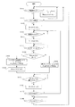
図7は、画像形成装置の電源がオンされてから実施される制御を説明するフローチャートである。画像形成装置の電源がオンされると、ステップ(以下、Sとする)1111でCPU301は、プリントが行われていない間、センサ115aの出力信号に基づき(図3参照)、給紙カセット111aに用紙Pが再セットされたか否かを判断する。S1111でCPU301は、用紙Pが再セットされたと判断した場合、S1112で用紙Pが再セットされたか否かの情報を保持しておくための再セットフラグをオンし、処理をS1111に戻す。S1111でCPU301は、用紙Pが再セットされていないと判断した場合、S1121に処理を進める。S1121でCPU301は、プリントが開始されたか否かを判断する。S1121でCPU301は、プリントが開始されていないと判断した場合、S1111に処理を戻し、プリントが開始されたと判断した場合、処理をS1125に進める。S1125でCPU301は、引き抜きローラ119を駆動するために、モータ123の回転を開始する。
[Paper Control Processing from
FIG. 7 is a flowchart illustrating control performed after the power of the image forming apparatus is turned on. When the power of the image forming apparatus is turned on, in step 1111 (hereinafter referred to as S), the
S1131でCPU301は、画像形成ユニット120の状況や、既に給紙した先行紙との間隔から、給紙タイミングか否かを判断する。S1131でCPU301は、給紙タイミングではないと判断した場合、処理をS1131に戻し、給紙タイミングであると判断した場合、処理をS1141に進める。S1141でCPU301は、給紙ピックアップローラ113a及び分離ローラ114aを駆動するために、モータ121の回転を開始し、給紙カセット111aの用紙Pの給紙を開始する。これは、図5で説明した時刻T1に相当する。
In S1131, the
S1151でCPU301は、用紙Pの搬送方向における引き抜きローラ119の上流側に設けられたセンサ117の出力が、オフからオンに変化したか否かを判断する。S1151でCPU301は、センサ117がオンに変化していないと判断した場合、処理をS1151に戻し、センサ117がオンに変化したと判断した場合、処理をS1161に進める。S1161でCPU301は、再セットフラグがオンとなっているか否かを判断する。S1161でCPU301は、再セットフラグがオンとなっていると判断した場合、処理をS1162に進める。S1162でCPU301は、図5(c)で説明したサイズ不一致検知モードでモータ121の回転を停止させるタイミングを算出する。具体的には、CPU301は、上述した式(2)を用いて、時刻T3−2を算出する。S1163でCPU301は、再セットフラグをオフにし、処理をS1171に進める。
In S1151, the
S1161でCPU301は、再セットフラグがオフであると判断した場合、処理をS1165に進める。S1165でCPU301は、図5(b)で説明した通常モードでモータ121の回転を停止させるタイミングを算出し、処理をS1171に進める。具体的には、CPU301は、上述した式(1)を用いて、時刻T3−1を算出する。S1171でCPU301は、タイマ291を参照することにより、モータ121の回転を停止させるタイミングになったか否かを判断する。具体的には、CPU301は、サイズ不一致検知モードの場合には時刻T3−2となったか否か、また、通常モードの場合には時刻T3−1となったか否か、を判断する。
When the
S1171でCPU301は、モータ121の回転を停止させるタイミングになっていないと判断した場合、処理をS1171に戻す。S1171でCPU301は、モータ121の回転を停止させるタイミングになったと判断した場合、S1181でモータ121の回転を停止させる。図5で説明したように、モータ121で駆動されるローラは、ワンウェイクラッチを有する構成である。このため、モータ121が停止された後も、用紙Pは引き抜きローラ119によって搬送され、給紙ピックアップローラ113aから引き抜かれていく。
When the
S1191でCPU301は、プリントジョブが複数枚のプリントである場合のために、次の用紙Pの給紙があるか否かを判断する。S1191でCPU301は、次の用紙Pの給紙が必要ないと判断した場合、処理をS1195に進める。S1195でCPU301は、プリントを終了するか否かを判断し、プリントを終了しないと判断した場合は処理をS1195に戻し、プリントを終了すると判断した場合は処理をS1111に戻す。即ち、CPU301は、プリントを終了したら、用紙Pの再セットの監視とプリント開始待ちの状態に戻る。S1191でCPU301は、次の用紙Pの給紙が必要であると判断した場合、処理をS1131に戻して、給紙タイミングとなるまで待機する。なお、図7では、給紙カセット111aからのプリントジョブに関して説明したが、給紙カセット111bや給紙トレイ111cからのプリントジョブに関しても同様であり、説明を省略する。このような制御により、用紙Pが再セットされた後に、サイズ不一致検知モードで給紙制御を実施することを可能にしている。
In S1191, the
以上説明したように、本実施の形態によれば、給紙口へ用紙をセットした後の1枚目の給紙においては、サイズ不一致となる可能性があるため、給紙ピックアップローラの駆動時間を短くする。給紙ピックアップローラの駆動時間を短くすることで、2枚目が連続して給紙されることを防止し、用紙の実サイズに対して、設定サイズが長い場合でも、サイズ不一致を検知することが可能となる。また、用紙の2枚目以降は、給紙ピックアップローラの近傍まで用紙の後端を搬送させるため、用紙の搬送を安定させることができる。 As described above, according to the present embodiment, the size of the first sheet of paper after the paper is set in the paper feed port may be inconsistent. Therefore, the drive time of the paper feed pickup roller To shorten. By shortening the drive time of the paper feed pickup roller, it is possible to prevent the second sheet from being continuously fed, and to detect a size mismatch with the actual size of the paper even if the set size is long. Is possible. Further, since the rear end of the paper is conveyed to the vicinity of the paper feed pickup roller for the second and subsequent sheets of paper, the transfer of the paper can be stabilized.
なお、上述した実施の形態では、サイズ不一致検知モードで給紙制御が行われる1枚目の用紙Pと、通常モードで給紙制御が行われる2枚目以降の用紙Pは、用紙長が同じとしている。また、上述した実施の形態では、モータ121、122等の駆動時間により給紙制御を行っているが、用紙Pが搬送される距離を制御する構成としてもよい。即ち、CPU301は、所定の条件を満たした場合に、給紙カセット111a等から給紙された1枚目の用紙を給紙ピックアップローラ113a等により搬送する距離を、2枚目以降の用紙を搬送する距離よりも短い距離にする。また、CPU301は、1枚目の用紙を給紙カセット111aにより搬送する距離を、画像形成装置で使用が許可されている用紙のサイズの中で、最も小さい用紙のサイズに基づき算出する。そして、CPU301は、2枚目以降の用紙を給紙カセット111aにより搬送する距離を、給紙カセット111a等に積載されている用紙のサイズに基づき算出する。
In the above-described embodiment, the first sheet P for which the paper feed control is performed in the size mismatch detection mode and the second and subsequent sheets P for which the paper feed control is performed in the normal mode have the same paper length. It is supposed to be. Further, in the above-described embodiment, the paper feed control is performed by the driving time of the
以上、本実施の形態によれば、用紙の搬送を安定させつつ、実際の用紙長と設定された用紙長が一致しないことを検知できるようにすることができる。 As described above, according to the present embodiment, it is possible to detect that the actual paper length and the set paper length do not match while stabilizing the paper transport.
111a 給紙カセット
113a 給紙ピックアップローラ
121 モータ
301 CPU
Claims (15)
記録材が積載される積載部と、
前記積載部に積載された記録材のサイズを設定する設定手段と、
前記積載部に積載された記録材を搬送路に給紙する給紙手段と、
前記給紙手段により給紙される記録材を搬送する搬送手段と、
前記搬送手段により搬送される記録材の搬送方向のサイズを検知するサイズ検知手段と、
前記給紙手段を駆動する駆動手段と、
前記駆動手段を制御する制御手段と、
を備え、
前記制御手段は、前記給紙手段が記録材を給紙できない状態から給紙できる状態になった後の最初の1枚目の記録材を給紙する際の前記駆動手段を駆動する時間を、前記設定手段により設定された記録材のサイズにかかわらず、所定のサイズの記録材を給紙する際の第1時間に決定し、前記給紙手段により給紙された前記1枚目の記録材のサイズが前記サイズ検知手段により検知され、検知された前記1枚目の記録材のサイズが前記設定手段により設定されたサイズと一致することが判定された場合には、その次に記録材を給紙する際の前記駆動手段を駆動する時間を前記第1時間以上であり、且つ前記設定手段により設定された記録材のサイズに応じた異なる時間に決定することを特徴とする画像形成装置。 It is an image forming device
The loading section where the recording material is loaded and
A setting means for setting the size of the recording material loaded on the loading unit, and
A paper feeding means for feeding the recording material loaded on the loading unit into the transport path, and
A transport means for transporting the recording material fed by the paper feed means, and
A size detecting means for detecting the size of the recording material conveyed by the conveying means in the conveying direction, and a size detecting means.
The drive means for driving the paper feed means and
A control means for controlling the drive means and
With
The control means determines the time for driving the drive means when feeding the first first recording material after the paper feeding means is in a state where the recording material cannot be fed to a state where the recording material can be fed. Regardless of the size of the recording material set by the setting means, the first recording material is determined to be the first time when the recording material of a predetermined size is fed and is fed by the paper feeding means. If the size of the first recording material is detected by the size detecting means and it is determined that the size of the detected first recording material matches the size set by the setting means, then the recording material is used. An image forming apparatus, characterized in that the time for driving the driving means at the time of feeding paper is determined to be the first time or more and different times according to the size of the recording material set by the setting means.
記録材が積載される積載部と、
前記積載部に積載された記録材のサイズを設定する設定手段と、
前記積載部に積載された記録材を搬送路に給紙する給紙手段と、
前記給紙手段により給紙される記録材を搬送する搬送手段と、
前記搬送手段により搬送される記録材の搬送方向のサイズを検知するサイズ検知手段と、
前記給紙手段を制御する制御手段と、
を備え、
前記制御手段は、前記給紙手段が記録材を給紙できない状態から給紙できる状態になった後の最初の1枚目の記録材を前記給紙手段により搬送する距離を、前記設定手段により設定された記録材のサイズにかかわらず、前記画像形成装置で使用が許可されている記録材のサイズの中で、最も小さい記録材のサイズに応じた第1距離に決定し、前記給紙手段により給紙された前記1枚目の記録材のサイズが前記サイズ検知手段により検知され、検知された前記1枚目の記録材のサイズが前記設定手段により設定されたサイズと異なることが判定された場合には、その次に記録材を給紙する際の前記給紙手段により搬送する距離を前記第1距離に決定し、検知された前記1枚目の記録材のサイズが前記設定手段により設定されたサイズと同じであることが判定された場合には、その次に記録材を給紙する際の前記給紙手段により搬送する距離を前記設定手段により設定された記録材のサイズに基づいて決定することを特徴とする画像形成装置。 It is an image forming device
The loading section where the recording material is loaded and
A setting means for setting the size of the recording material loaded on the loading unit, and
A paper feeding means for feeding the recording material loaded on the loading unit into the transport path, and
A transport means for transporting the recording material fed by the paper feed means, and
A size detecting means for detecting the size of the recording material conveyed by the conveying means in the conveying direction, and a size detecting means.
A control means for controlling the paper feed means and
With
The control means uses the setting means to set the distance at which the first first recording material is conveyed by the paper feeding means after the recording material cannot be fed to the recording material. Regardless of the size of the set recording material, the first distance is determined according to the size of the smallest recording material among the sizes of the recording material permitted to be used in the image forming apparatus, and the paper feeding means. The size of the first recording material fed by the paper is detected by the size detecting means, and it is determined that the detected size of the first recording material is different from the size set by the setting means. In this case, the distance to be conveyed by the paper feeding means when the recording material is then fed is determined as the first distance, and the detected size of the first recording material is determined by the setting means. If it is determined that the size is the same as the set size, the distance to be conveyed by the paper feeding means when the recording material is next fed is based on the size of the recording material set by the setting means. An image forming apparatus characterized in that the determination is made.
前記サイズ検知手段は、前記センサの検知結果に基づいて記録材のサイズを検知することを特徴とする請求項1又は2に記載の画像形成装置。 A sensor provided on the downstream side of the paper feeding means in the transport direction of the recording material and detecting the transported recording material is provided.
The image forming apparatus according to claim 1 or 2, wherein the size detecting means detects the size of a recording material based on the detection result of the sensor.
前記制御手段は、前記設定手段により設定された記録材のサイズと、前記サイズ検知手段により検知された前記1枚目の記録材のサイズが一致しなかった場合には、記録材のサイズが一致しなかったことを前記表示部に表示させることを特徴とする請求項1又は請求項2に記載の画像形成装置。 A display unit for displaying information about the image forming apparatus is provided.
In the control means, when the size of the recording material set by the setting means and the size of the first recording material detected by the size detecting means do not match, the size of the recording material is one. The image forming apparatus according to claim 1 or 2, wherein the display unit displays what has not been done.
前記表示部に表示された前記候補の中から記録材のサイズを決定するために操作される操作部と、
を備え、
前記設定手段は、前記操作部が操作されて前記表示部に表示された前記候補の中から記録材のサイズが決定されたことに応じて、前記積載部に積載された記録材のサイズを設定することを特徴とする請求項11に記載の画像形成装置。 A display unit that displays candidates for the size of the recording material loaded on the loading unit based on the information for setting the size of the recording material loaded on the loading unit.
An operation unit operated to determine the size of the recording material from the candidates displayed on the display unit, and
With
The setting means sets the size of the recording material loaded on the loading unit in response to the operation of the operating unit and the determination of the size of the recording material from the candidates displayed on the display unit. The image forming apparatus according to claim 11, wherein the image forming apparatus is used.
を有し、
前記制御手段は、前記給紙手段から前記記録材を引き抜くように、前記駆動手段を停止させた後も前記搬送手段により記録材を搬送させることを特徴とする請求項1又は請求項4に記載の画像形成装置。 A one-way clutch provided between the paper feeding means and the driving means,
Have,
The first or fourth aspect of the present invention, wherein the control means conveys the recording material by the conveying means even after the driving means is stopped so as to pull out the recording material from the paper feeding means. Image forming device.
Priority Applications (1)
| Application Number | Priority Date | Filing Date | Title |
|---|---|---|---|
| JP2015175719A JP6771872B2 (en) | 2015-09-07 | 2015-09-07 | Image forming device |
Applications Claiming Priority (1)
| Application Number | Priority Date | Filing Date | Title |
|---|---|---|---|
| JP2015175719A JP6771872B2 (en) | 2015-09-07 | 2015-09-07 | Image forming device |
Publications (3)
| Publication Number | Publication Date |
|---|---|
| JP2017052572A JP2017052572A (en) | 2017-03-16 |
| JP2017052572A5 JP2017052572A5 (en) | 2018-11-01 |
| JP6771872B2 true JP6771872B2 (en) | 2020-10-21 |
Family
ID=58316975
Family Applications (1)
| Application Number | Title | Priority Date | Filing Date |
|---|---|---|---|
| JP2015175719A Active JP6771872B2 (en) | 2015-09-07 | 2015-09-07 | Image forming device |
Country Status (1)
| Country | Link |
|---|---|
| JP (1) | JP6771872B2 (en) |
Families Citing this family (1)
| Publication number | Priority date | Publication date | Assignee | Title |
|---|---|---|---|---|
| JP6957238B2 (en) | 2017-06-30 | 2021-11-02 | キヤノン株式会社 | Feeding device |
Family Cites Families (6)
| Publication number | Priority date | Publication date | Assignee | Title |
|---|---|---|---|---|
| JPH06298411A (en) * | 1993-04-19 | 1994-10-25 | Canon Inc | Control method for sheet material feeder |
| JP2010217299A (en) * | 2009-03-13 | 2010-09-30 | Oki Data Corp | Image forming apparatus |
| JP2010222070A (en) * | 2009-03-19 | 2010-10-07 | Sharp Corp | Paper conveying device and image forming device equipped with the same |
| JP5581811B2 (en) * | 2010-05-28 | 2014-09-03 | 株式会社リコー | Image forming apparatus |
| JP6007693B2 (en) * | 2012-09-13 | 2016-10-12 | 株式会社リコー | Image forming apparatus |
| JP6452021B2 (en) * | 2013-10-29 | 2019-01-16 | 株式会社リコー | Image forming apparatus |
-
2015
- 2015-09-07 JP JP2015175719A patent/JP6771872B2/en active Active
Also Published As
| Publication number | Publication date |
|---|---|
| JP2017052572A (en) | 2017-03-16 |
Similar Documents
| Publication | Publication Date | Title |
|---|---|---|
| US9471024B1 (en) | Image reading device and image forming apparatus | |
| US10239717B2 (en) | Image forming apparatus, image forming method, and sheet-feeding apparatus | |
| JP2017090911A (en) | Image forming apparatus and program | |
| US9927753B2 (en) | Image forming apparatus | |
| US9883065B2 (en) | Image reading device, image forming apparatus, and image reading method | |
| JP7521079B2 (en) | Image forming device | |
| US9815646B2 (en) | Image forming apparatus | |
| US20180097947A1 (en) | Image forming apparatus | |
| US11186104B2 (en) | Image forming system | |
| US20160012320A1 (en) | Image forming apparatus | |
| JP5200667B2 (en) | Transmitted light amount measuring apparatus, medium identifying apparatus, medium conveying apparatus, and image forming apparatus | |
| JP6771872B2 (en) | Image forming device | |
| JP2010211062A (en) | Image forming apparatus | |
| JP2010264608A (en) | Image forming apparatus | |
| US11150586B2 (en) | Image forming system | |
| US10924619B2 (en) | Image forming system | |
| JP6628524B2 (en) | Image forming apparatus, paper feeding method | |
| JP2020108094A (en) | Document reading device and image forming apparatus | |
| US20240297940A1 (en) | Processing device, processing method, and storage medium | |
| US20240300761A1 (en) | Image forming apparatus, control method for controlling image forming apparatus, and storage medium | |
| JP2024128976A (en) | Image reader | |
| JP6775918B2 (en) | Image forming device | |
| JP2025008688A (en) | Image reader | |
| JP6579797B2 (en) | Image forming apparatus | |
| JP2023043539A (en) | Sheet feeding device and image forming device |
Legal Events
| Date | Code | Title | Description |
|---|---|---|---|
| RD03 | Notification of appointment of power of attorney |
Free format text: JAPANESE INTERMEDIATE CODE: A7423 Effective date: 20160215 |
|
| RD04 | Notification of resignation of power of attorney |
Free format text: JAPANESE INTERMEDIATE CODE: A7424 Effective date: 20160215 |
|
| A521 | Written amendment |
Free format text: JAPANESE INTERMEDIATE CODE: A523 Effective date: 20160401 |
|
| RD04 | Notification of resignation of power of attorney |
Free format text: JAPANESE INTERMEDIATE CODE: A7424 Effective date: 20171201 |
|
| A621 | Written request for application examination |
Free format text: JAPANESE INTERMEDIATE CODE: A621 Effective date: 20180907 |
|
| A521 | Written amendment |
Free format text: JAPANESE INTERMEDIATE CODE: A523 Effective date: 20180920 |
|
| A977 | Report on retrieval |
Free format text: JAPANESE INTERMEDIATE CODE: A971007 Effective date: 20190606 |
|
| A131 | Notification of reasons for refusal |
Free format text: JAPANESE INTERMEDIATE CODE: A131 Effective date: 20190625 |
|
| A521 | Written amendment |
Free format text: JAPANESE INTERMEDIATE CODE: A523 Effective date: 20190826 |
|
| A131 | Notification of reasons for refusal |
Free format text: JAPANESE INTERMEDIATE CODE: A131 Effective date: 20200204 |
|
| A521 | Written amendment |
Free format text: JAPANESE INTERMEDIATE CODE: A523 Effective date: 20200330 |
|
| TRDD | Decision of grant or rejection written | ||
| A01 | Written decision to grant a patent or to grant a registration (utility model) |
Free format text: JAPANESE INTERMEDIATE CODE: A01 Effective date: 20200901 |
|
| A61 | First payment of annual fees (during grant procedure) |
Free format text: JAPANESE INTERMEDIATE CODE: A61 Effective date: 20200930 |
|
| R151 | Written notification of patent or utility model registration |
Ref document number: 6771872 Country of ref document: JP Free format text: JAPANESE INTERMEDIATE CODE: R151 |