JP6771522B2 - Buffer - Google Patents
Buffer Download PDFInfo
- Publication number
- JP6771522B2 JP6771522B2 JP2018190871A JP2018190871A JP6771522B2 JP 6771522 B2 JP6771522 B2 JP 6771522B2 JP 2018190871 A JP2018190871 A JP 2018190871A JP 2018190871 A JP2018190871 A JP 2018190871A JP 6771522 B2 JP6771522 B2 JP 6771522B2
- Authority
- JP
- Japan
- Prior art keywords
- cylinder
- intermediate cylinder
- seal ring
- chamber
- groove
- Prior art date
- Legal status (The legal status is an assumption and is not a legal conclusion. Google has not performed a legal analysis and makes no representation as to the accuracy of the status listed.)
- Active
Links
- 239000007788 liquid Substances 0.000 claims description 22
- 239000006096 absorbing agent Substances 0.000 claims description 20
- 230000035939 shock Effects 0.000 claims description 20
- 238000013016 damping Methods 0.000 claims description 17
- 230000002093 peripheral effect Effects 0.000 claims description 9
- 238000003754 machining Methods 0.000 description 5
- 239000011324 bead Substances 0.000 description 4
- 238000005452 bending Methods 0.000 description 3
- 238000003780 insertion Methods 0.000 description 2
- 230000037431 insertion Effects 0.000 description 2
- 238000000034 method Methods 0.000 description 2
- 238000005192 partition Methods 0.000 description 2
- 238000007789 sealing Methods 0.000 description 2
- 230000004323 axial length Effects 0.000 description 1
- 230000006835 compression Effects 0.000 description 1
- 238000007906 compression Methods 0.000 description 1
- 230000008602 contraction Effects 0.000 description 1
- 239000012530 fluid Substances 0.000 description 1
- 239000000463 material Substances 0.000 description 1
- 229920003002 synthetic resin Polymers 0.000 description 1
- 239000000057 synthetic resin Substances 0.000 description 1
Images


Classifications
-
- F—MECHANICAL ENGINEERING; LIGHTING; HEATING; WEAPONS; BLASTING
- F16—ENGINEERING ELEMENTS AND UNITS; GENERAL MEASURES FOR PRODUCING AND MAINTAINING EFFECTIVE FUNCTIONING OF MACHINES OR INSTALLATIONS; THERMAL INSULATION IN GENERAL
- F16J—PISTONS; CYLINDERS; SEALINGS
- F16J15/00—Sealings
- F16J15/02—Sealings between relatively-stationary surfaces
- F16J15/06—Sealings between relatively-stationary surfaces with solid packing compressed between sealing surfaces
- F16J15/062—Sealings between relatively-stationary surfaces with solid packing compressed between sealing surfaces characterised by the geometry of the seat
-
- F—MECHANICAL ENGINEERING; LIGHTING; HEATING; WEAPONS; BLASTING
- F16—ENGINEERING ELEMENTS AND UNITS; GENERAL MEASURES FOR PRODUCING AND MAINTAINING EFFECTIVE FUNCTIONING OF MACHINES OR INSTALLATIONS; THERMAL INSULATION IN GENERAL
- F16F—SPRINGS; SHOCK-ABSORBERS; MEANS FOR DAMPING VIBRATION
- F16F9/00—Springs, vibration-dampers, shock-absorbers, or similarly-constructed movement-dampers using a fluid or the equivalent as damping medium
- F16F9/10—Springs, vibration-dampers, shock-absorbers, or similarly-constructed movement-dampers using a fluid or the equivalent as damping medium using liquid only; using a fluid of which the nature is immaterial
- F16F9/14—Devices with one or more members, e.g. pistons, vanes, moving to and fro in chambers and using throttling effect
- F16F9/16—Devices with one or more members, e.g. pistons, vanes, moving to and fro in chambers and using throttling effect involving only straight-line movement of the effective parts
- F16F9/18—Devices with one or more members, e.g. pistons, vanes, moving to and fro in chambers and using throttling effect involving only straight-line movement of the effective parts with a closed cylinder and a piston separating two or more working spaces therein
- F16F9/185—Bitubular units
- F16F9/187—Bitubular units with uni-directional flow of damping fluid through the valves
-
- F—MECHANICAL ENGINEERING; LIGHTING; HEATING; WEAPONS; BLASTING
- F16—ENGINEERING ELEMENTS AND UNITS; GENERAL MEASURES FOR PRODUCING AND MAINTAINING EFFECTIVE FUNCTIONING OF MACHINES OR INSTALLATIONS; THERMAL INSULATION IN GENERAL
- F16F—SPRINGS; SHOCK-ABSORBERS; MEANS FOR DAMPING VIBRATION
- F16F9/00—Springs, vibration-dampers, shock-absorbers, or similarly-constructed movement-dampers using a fluid or the equivalent as damping medium
- F16F9/32—Details
- F16F9/3207—Constructional features
- F16F9/3235—Constructional features of cylinders
- F16F9/3257—Constructional features of cylinders in twin-tube type devices
-
- F—MECHANICAL ENGINEERING; LIGHTING; HEATING; WEAPONS; BLASTING
- F16—ENGINEERING ELEMENTS AND UNITS; GENERAL MEASURES FOR PRODUCING AND MAINTAINING EFFECTIVE FUNCTIONING OF MACHINES OR INSTALLATIONS; THERMAL INSULATION IN GENERAL
- F16F—SPRINGS; SHOCK-ABSORBERS; MEANS FOR DAMPING VIBRATION
- F16F9/00—Springs, vibration-dampers, shock-absorbers, or similarly-constructed movement-dampers using a fluid or the equivalent as damping medium
- F16F9/32—Details
- F16F9/36—Special sealings, including sealings or guides for piston-rods
- F16F9/369—Sealings for elements other than pistons or piston rods, e.g. valves
-
- F—MECHANICAL ENGINEERING; LIGHTING; HEATING; WEAPONS; BLASTING
- F16—ENGINEERING ELEMENTS AND UNITS; GENERAL MEASURES FOR PRODUCING AND MAINTAINING EFFECTIVE FUNCTIONING OF MACHINES OR INSTALLATIONS; THERMAL INSULATION IN GENERAL
- F16J—PISTONS; CYLINDERS; SEALINGS
- F16J15/00—Sealings
- F16J15/16—Sealings between relatively-moving surfaces
- F16J15/32—Sealings between relatively-moving surfaces with elastic sealings, e.g. O-rings
-
- F—MECHANICAL ENGINEERING; LIGHTING; HEATING; WEAPONS; BLASTING
- F16—ENGINEERING ELEMENTS AND UNITS; GENERAL MEASURES FOR PRODUCING AND MAINTAINING EFFECTIVE FUNCTIONING OF MACHINES OR INSTALLATIONS; THERMAL INSULATION IN GENERAL
- F16F—SPRINGS; SHOCK-ABSORBERS; MEANS FOR DAMPING VIBRATION
- F16F2222/00—Special physical effects, e.g. nature of damping effects
- F16F2222/12—Fluid damping
-
- F—MECHANICAL ENGINEERING; LIGHTING; HEATING; WEAPONS; BLASTING
- F16—ENGINEERING ELEMENTS AND UNITS; GENERAL MEASURES FOR PRODUCING AND MAINTAINING EFFECTIVE FUNCTIONING OF MACHINES OR INSTALLATIONS; THERMAL INSULATION IN GENERAL
- F16F—SPRINGS; SHOCK-ABSORBERS; MEANS FOR DAMPING VIBRATION
- F16F2226/00—Manufacturing; Treatments
- F16F2226/04—Assembly or fixing methods; methods to form or fashion parts
-
- F—MECHANICAL ENGINEERING; LIGHTING; HEATING; WEAPONS; BLASTING
- F16—ENGINEERING ELEMENTS AND UNITS; GENERAL MEASURES FOR PRODUCING AND MAINTAINING EFFECTIVE FUNCTIONING OF MACHINES OR INSTALLATIONS; THERMAL INSULATION IN GENERAL
- F16F—SPRINGS; SHOCK-ABSORBERS; MEANS FOR DAMPING VIBRATION
- F16F2230/00—Purpose; Design features
- F16F2230/30—Sealing arrangements
-
- F—MECHANICAL ENGINEERING; LIGHTING; HEATING; WEAPONS; BLASTING
- F16—ENGINEERING ELEMENTS AND UNITS; GENERAL MEASURES FOR PRODUCING AND MAINTAINING EFFECTIVE FUNCTIONING OF MACHINES OR INSTALLATIONS; THERMAL INSULATION IN GENERAL
- F16F—SPRINGS; SHOCK-ABSORBERS; MEANS FOR DAMPING VIBRATION
- F16F2230/00—Purpose; Design features
- F16F2230/36—Holes, slots or the like
-
- F—MECHANICAL ENGINEERING; LIGHTING; HEATING; WEAPONS; BLASTING
- F16—ENGINEERING ELEMENTS AND UNITS; GENERAL MEASURES FOR PRODUCING AND MAINTAINING EFFECTIVE FUNCTIONING OF MACHINES OR INSTALLATIONS; THERMAL INSULATION IN GENERAL
- F16F—SPRINGS; SHOCK-ABSORBERS; MEANS FOR DAMPING VIBRATION
- F16F2232/00—Nature of movement
- F16F2232/08—Linear
-
- F—MECHANICAL ENGINEERING; LIGHTING; HEATING; WEAPONS; BLASTING
- F16—ENGINEERING ELEMENTS AND UNITS; GENERAL MEASURES FOR PRODUCING AND MAINTAINING EFFECTIVE FUNCTIONING OF MACHINES OR INSTALLATIONS; THERMAL INSULATION IN GENERAL
- F16F—SPRINGS; SHOCK-ABSORBERS; MEANS FOR DAMPING VIBRATION
- F16F2234/00—Shape
- F16F2234/02—Shape cylindrical
-
- F—MECHANICAL ENGINEERING; LIGHTING; HEATING; WEAPONS; BLASTING
- F16—ENGINEERING ELEMENTS AND UNITS; GENERAL MEASURES FOR PRODUCING AND MAINTAINING EFFECTIVE FUNCTIONING OF MACHINES OR INSTALLATIONS; THERMAL INSULATION IN GENERAL
- F16F—SPRINGS; SHOCK-ABSORBERS; MEANS FOR DAMPING VIBRATION
- F16F9/00—Springs, vibration-dampers, shock-absorbers, or similarly-constructed movement-dampers using a fluid or the equivalent as damping medium
- F16F9/06—Springs, vibration-dampers, shock-absorbers, or similarly-constructed movement-dampers using a fluid or the equivalent as damping medium using both gas and liquid
- F16F9/062—Bi-tubular units
-
- F—MECHANICAL ENGINEERING; LIGHTING; HEATING; WEAPONS; BLASTING
- F16—ENGINEERING ELEMENTS AND UNITS; GENERAL MEASURES FOR PRODUCING AND MAINTAINING EFFECTIVE FUNCTIONING OF MACHINES OR INSTALLATIONS; THERMAL INSULATION IN GENERAL
- F16F—SPRINGS; SHOCK-ABSORBERS; MEANS FOR DAMPING VIBRATION
- F16F9/00—Springs, vibration-dampers, shock-absorbers, or similarly-constructed movement-dampers using a fluid or the equivalent as damping medium
- F16F9/06—Springs, vibration-dampers, shock-absorbers, or similarly-constructed movement-dampers using a fluid or the equivalent as damping medium using both gas and liquid
- F16F9/064—Units characterised by the location or shape of the expansion chamber
-
- F—MECHANICAL ENGINEERING; LIGHTING; HEATING; WEAPONS; BLASTING
- F16—ENGINEERING ELEMENTS AND UNITS; GENERAL MEASURES FOR PRODUCING AND MAINTAINING EFFECTIVE FUNCTIONING OF MACHINES OR INSTALLATIONS; THERMAL INSULATION IN GENERAL
- F16F—SPRINGS; SHOCK-ABSORBERS; MEANS FOR DAMPING VIBRATION
- F16F9/00—Springs, vibration-dampers, shock-absorbers, or similarly-constructed movement-dampers using a fluid or the equivalent as damping medium
- F16F9/32—Details
- F16F9/3207—Constructional features
- F16F9/3235—Constructional features of cylinders
-
- F—MECHANICAL ENGINEERING; LIGHTING; HEATING; WEAPONS; BLASTING
- F16—ENGINEERING ELEMENTS AND UNITS; GENERAL MEASURES FOR PRODUCING AND MAINTAINING EFFECTIVE FUNCTIONING OF MACHINES OR INSTALLATIONS; THERMAL INSULATION IN GENERAL
- F16F—SPRINGS; SHOCK-ABSORBERS; MEANS FOR DAMPING VIBRATION
- F16F9/00—Springs, vibration-dampers, shock-absorbers, or similarly-constructed movement-dampers using a fluid or the equivalent as damping medium
- F16F9/32—Details
- F16F9/44—Means on or in the damper for manual or non-automatic adjustment; such means combined with temperature correction
- F16F9/46—Means on or in the damper for manual or non-automatic adjustment; such means combined with temperature correction allowing control from a distance, i.e. location of means for control input being remote from site of valves, e.g. on damper external wall
Description
本発明は、緩衝器に関する。 The present invention relates to a shock absorber.
従来の緩衝器が特許文献1に開示されている。これは、ソレノイドを用いて減衰力を調整する複筒式油圧緩衝器であって、シリンダと、シリンダの外周を覆ってシリンダとの間に排出通路(環状通路)を区画する中間筒(セパレータチューブ)と、中間筒の外周を覆って中間筒との間にリザーバを区画する外筒(アウタチューブ)とを備えている。減衰力を調整する減衰弁は、排出通路とリザーバとの間に設けられている。 A conventional shock absorber is disclosed in Patent Document 1. This is a double-cylinder hydraulic shock absorber that adjusts the damping force using a solenoid, and is an intermediate cylinder (separator tube) that covers the cylinder and the outer circumference of the cylinder to partition the discharge passage (annular passage) between the cylinders. ) And an outer cylinder (outer tube) that covers the outer circumference of the intermediate cylinder and partitions the reservoir between the intermediate cylinder and the intermediate cylinder. A damping valve for adjusting the damping force is provided between the discharge passage and the reservoir.
中間筒は、縮径された両端部の内周面に、排出通路を閉塞するシールリングを収容可能な断面凹状のシールリング溝を有している。中間筒のシールリング溝の両側面のうち、中間筒の軸端側に位置する側面は、軸中央側に位置する側面よりも、中間筒の軸方向と直交する面に対する傾斜角度が大きくなるように設定されている。 The intermediate cylinder has a seal ring groove having a concave cross section on the inner peripheral surfaces of both ends of the reduced diameter, which can accommodate a seal ring that closes the discharge passage. Of the side surfaces of the seal ring groove of the intermediate cylinder, the side surface located on the shaft end side of the intermediate cylinder has a larger inclination angle with respect to the surface orthogonal to the axial direction of the intermediate cylinder than the side surface located on the shaft center side. Is set to.
シールリング溝は、例えば、片持ちツールが中間筒内で回転させられ、片持ちツールの先端部に設けられた凸部が中間筒の材料を径方向に押し出すように塑性変形させることで、外側に膨出するビードとともに形成される。 The seal ring groove is formed by, for example, the cantilever tool being rotated in the intermediate cylinder and the convex portion provided at the tip of the cantilever tool being plastically deformed so as to push out the material of the intermediate cylinder in the radial direction. Formed with a bead that swells in.
上記の場合、中間筒の軸端側に位置する側面の傾斜角度が大きいため、シールリング溝内のシールリングが排出通路の油圧で軸端側(低圧側)に押されたときに、シールリングの一部が軸端側からはみ出して傷付き、その傷により密封性が損なわれる懸念がある。 In the above case, since the inclination angle of the side surface located on the shaft end side of the intermediate cylinder is large, the seal ring in the seal ring groove is pushed to the shaft end side (low pressure side) by the hydraulic pressure of the discharge passage. There is a concern that a part of the shaft may protrude from the shaft end side and be damaged, and the damage may impair the sealing performance.
一方、片持ちツールは、中間筒からの加工反力で撓むという事情がある。シールリング溝は、片持ちツールの撓みに起因し、加工精度にばらつきが生じ、寸法品質が安定しない懸念がある。特に、シールリング溝側面の傾斜角度が小さいと、加工反力が大きく、片持ちツールの撓みが生じ易いという事情がある。 On the other hand, the cantilever tool has a situation that it bends due to the processing reaction force from the intermediate cylinder. There is a concern that the dimensional quality of the seal ring groove may not be stable due to variations in machining accuracy due to bending of the cantilever tool. In particular, when the inclination angle of the side surface of the seal ring groove is small, the machining reaction force is large and the cantilever tool tends to bend.
本発明は、上記従来の実情に鑑みてなされたものであって、寸法品質を向上させることができ、シールリングの密封性を確保することができる緩衝器を提供することを解決すべき課題としている。 The present invention has been made in view of the above-mentioned conventional circumstances, and it is a problem to be solved to provide a shock absorber capable of improving dimensional quality and ensuring the sealability of a seal ring. There is.
本発明の緩衝器は、シリンダと、シリンダ内に移動可能に挿入されるピストンロッドと、ピストンロッドに連結されるピストンと、シリンダの外周を覆う外筒と、シリンダと外筒との間に配置され、シリンダの外周を覆う中間筒と、を備える。ピストンは、シリンダ内をピストンロッドが位置する側である第1室とその反対側である第2室とに分ける。シリンダと外筒との間には環状のリザーバが形成される。中間筒は、リザーバの内側に配置される。
さらに、緩衝器は、リザーバから第2室へ向かう液体の流れのみを許容する吸込通路と、第2室から第1室へ向かう液体の流れのみを許容する整流通路と、シリンダ内からリザーバへ向かう液体の流れに抵抗を与える減衰弁と、を備えている。中間筒とシリンダと減衰弁との間には、シリンダ内に連通する排出通路が形成される。中間筒は、内周面に、排出通路を閉塞するシールリングを収容可能な断面凹状の溝を有している。中間筒の溝の両側面のうち中間筒の軸端側に位置する側面が中間筒の軸方向と直交する面との間に形成される角度をθ1とし、中間筒の軸中央側に位置する側面が前記面との間に形成される角度をθ2とした場合に、θ1<θ2の関係を満たすように設定されている。
The shock absorber of the present invention is arranged between a cylinder, a piston rod movably inserted into the cylinder, a piston connected to the piston rod, an outer cylinder covering the outer periphery of the cylinder, and the cylinder and the outer cylinder. An intermediate cylinder that covers the outer periphery of the cylinder is provided. The piston is divided into a first chamber on the side where the piston rod is located and a second chamber on the opposite side in the cylinder. An annular reservoir is formed between the cylinder and the outer cylinder. The intermediate tube is located inside the reservoir.
Further, the shock absorber has a suction passage that allows only the flow of liquid from the reservoir to the second chamber, a rectifying passage that allows only the flow of liquid from the second chamber to the first chamber, and an internal cylinder to the reservoir. It is equipped with a damping valve that resists the flow of liquid. A discharge passage communicating with the inside of the cylinder is formed between the intermediate cylinder, the cylinder, and the damping valve. The intermediate cylinder has a groove having a concave cross section on the inner peripheral surface, which can accommodate a seal ring that closes the discharge passage. Of both sides of the groove of the intermediate cylinder, the angle formed between the side surface of the intermediate cylinder located on the shaft end side and the surface orthogonal to the axial direction of the intermediate cylinder is θ1, and the side surface is located on the shaft center side of the intermediate cylinder. When the angle at which the side surface is formed with the surface is θ2, it is set so as to satisfy the relationship of θ1 <θ2.
シールリングが排出通路の油圧で中間筒の軸端側(低圧側)に押されても、軸端側の側面の角度θ1が軸中央側の側面の角度θ2より小さいため、シールリングが溝からはみ出すのを防止することができ、シールリングの密封性を確保することができる。 Even if the seal ring is pushed toward the shaft end side (low pressure side) of the intermediate cylinder by the hydraulic pressure of the discharge passage, the angle θ1 of the side surface on the shaft end side is smaller than the angle θ2 of the side surface on the shaft center side, so that the seal ring is removed from the groove. It is possible to prevent it from sticking out, and it is possible to ensure the sealing property of the seal ring.
中間筒の軸中央側の側面の角度θ2が軸端側の側面の角度θ1より大きいため、溝を成形する片持ちツールが中間壁から受ける加工反力を小さくすることができ、片持ちツールの撓みを低減することができる結果、寸法品質を向上させることができる。 Since the angle θ2 of the side surface on the shaft center side of the intermediate cylinder is larger than the angle θ1 on the side surface on the shaft end side, the machining reaction force received by the cantilever tool for forming the groove from the intermediate wall can be reduced, and the cantilever tool As a result of being able to reduce the deflection, the dimensional quality can be improved.
<実施形態1>
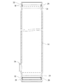
実施形態1を、図1〜図4に基づいて説明する。実施形態1の緩衝器10は、図1に示すように、略円筒状のシリンダ11と、シリンダ11内に往復摺動可能に挿入される略円柱状のピストン12と、ピストン12に連結される略円柱棒状のピストンロッド13と、シリンダ11の外周を覆う略円筒状の中間筒14と、中間筒14の外周を覆う略円筒状の外筒15と、を備えている。シリンダ11内は、ピストン12を挟んでピストンロッド13が位置する側となる第1室16とその反対側となる第2室17とに分画される。
<Embodiment 1>
The first embodiment will be described with reference to FIGS. 1 to 4. As shown in FIG. 1, the shock absorber 10 of the first embodiment is connected to a substantially
緩衝器10は、シリンダ11と中間筒14との間に、径方向断面が環状の排出通路18を有し、中間筒14と外筒15との間に、径方向断面が環状のリザーバ19を有し、排出通路18とリザーバ19とを連通する減衰弁21を有している。排出通路18は、シリンダ11に設けられた通孔22を介して第1室16と連通している。
The
作動流体としての液体である油液は、シリンダ11内の第1室16、第2室17及びリザーバ19に充填される。リザーバ19は、油液の他、気体を封入している。
The oil liquid, which is a liquid as a working fluid, is filled in the
緩衝器10は、シリンダ11の一端(図示下端)に装着されるベースバルブ23と、シリンダ11の他端(図示上端)及び外筒15の他端に装着されるロッドガイド24と、を備えている。ベースバルブ23は、リザーバ19側から第2室17側への油液の流通のみを許容する吸込通路25と、第2室17側の油液の圧力が一定の圧力に達したときに第2室17側の油液をリザーバ19側へリリーフする油路26と、を有している。
The
ピストン12は、第2室17側から第1室16側への油液の流通のみを許容する整流通路27と、第1室16側の油液の圧力が一定の圧力に達したときに第1室16側の油液を第2室17側へリリーフする油路28と、を有している。
The
ピストンロッド13は、ピストン12に固定される一端から第1室16を横断するように延び、ロッドガイド24を摺動可能に貫通してシリンダ11の外部に露出している。
The
図2に示すように、中間筒14の両端部(軸方向の両端部)は、スウェージング加工等によって縮径する形態になっている。中間筒14は、両端部に、外側へ膨出するビード29を有し、ビード29の内周面に、全周にわたって周回する溝31を有している。中間筒14の溝31は、内部に、シールリング32及びバックアップリング33を軸方向に並列に収容可能とされている。シールリング32は、中間筒14の溝31に装着された状態で、シリンダ11の外周面に密着する。排出通路18は、軸方向両端をシールリング32で閉塞されて区画される。
As shown in FIG. 2, both ends of the intermediate cylinder 14 (both ends in the axial direction) are reduced in diameter by swaging or the like. The
中間筒14は、ベースバルブ23寄りの部分に、外側(図2の左側)に突出するバーリング形状の嵌合部34を有している。外筒15は、嵌合部34と対向する位置に、嵌合部34より一回り大きいガイド部35を有している。
The
減衰弁21を含むユニット36は、ガイド部35内に固定されている。ユニット36のソレノイド部分は、嵌合部34内に嵌合され、排出通路18から嵌合部34内を経てリザーバ19へ向かう油液の流れを制御し、減衰力を発生する。
The
緩衝器10が収縮する際、ピストン12が図示下側に移動し、第2室17が圧縮され、第2室17内の油液がピストン12の整流通路27を介して第1室16側に移動する。収縮時、ピストンロッド13がシリンダ11内に侵入し、その侵入体積分の油液がシリンダ11から押し出されて排出通路18に流入しさらに排出通路18から減衰弁21を経てリザーバ19に排出される。減衰弁21は、排出通路18からリザーバ19へ向かう油液の流れに抵抗を付与し、シリンダ11内及び排出通路18の圧力を上昇させる。これにより、緩衝器10は圧側減衰力を発生する。
When the shock absorber 10 contracts, the
一方、緩衝器10が伸長する際、ピストン12が図示上側に移動し、第1室16が圧縮され、第1室16内の油液が排出通路18に流入しさらに排出通路18から減衰弁21を経てリザーバ19に排出される。減衰弁21は、排出通路18からリザーバ19へ向かう油液の流れに抵抗を付与し、第1室16及び排出通路18の圧力を上昇させる。伸長時、第2室17の容積が拡大し、その拡大分の油液がベースバルブ23の吸込通路25を通してリザーバ19から供給される。これにより、緩衝器10は伸側減衰力を発生する。
On the other hand, when the
上記のように、緩衝器10が伸縮する際、油液がシリンダ11内から排出通路18を介してリザーバ19へ排出される。シールリング32は、中間筒14の溝31内において、中間筒14の軸中央側となる排出通路18に臨む側(高圧側P2)に配置され、排出通路18から中間筒14の軸端側(低圧側P1、開口端側)へ向かう油圧を直接受ける。バックアップリング33は、中間筒14の溝31内において、中間筒14の軸端側となる排出通路18から離れる側にてシールリング32と隣接して配置され、排出通路18から圧力を受けたシールリング32が低圧側P1に変形するのを防止する。
As described above, when the
シールリング32は、ゴム製のOリングであって、自然状態ではシリンダ11の外周面の外径より小さい内径を有している。バックアップリング33は、合成樹脂製であって、シールリング32より高い剛性を有し、シールリング32と対応した環形状を呈している。図3に示すように、シールリング32の軸方向断面は円形をなし、バックアップリング33の軸方向断面は矩形をなしている。
The
図3に示すように、中間筒14の溝31は、軸方向断面が略角凹状をなし、軸方向に沿って配置される奥面37と、シールリング32及びバックアップリング33を挟んだ軸方向両側で互いに対向して配置される第1側面38及び第2側面39と、を有している。
As shown in FIG. 3, the
奥面37は、軸方向に所定の長さで延びる水平面である。奥面37の軸方向の長さは、溝31の溝幅に相当し、シールリング32とバックアップリング33の各軸方向寸法を加算した値より少し大きくされている。
The
第1側面38は、中間筒14の軸端側(低圧側P1)に位置するストレート状の側面であって、バックアップリング33と対面して当接可能に配置される。第1側面38の径方向外端と奥面37との間は、湾曲状の第1外曲面41で連結されている。第1側面38の径方向内端と中間筒14の内周面の軸端側部分との間は、湾曲状の第1内曲面42で連結されている。
The
第1側面38は、中間筒14の軸方向と直交する方向に沿った面PL1に対し、第1外曲面41側から第1内曲面42側へ行くにしたがって次第に軸端側(低圧側P1)へ変位するように、傾斜して配置されている。面PL1に対する第1側面38の角度θ1は、0度より大きく且つ5度未満に設定されている。
The
第2側面39は、第1側面38に対して中間筒14の軸中央側(高圧側P2)に位置するストレート状の側面であって、シールリング32と対面して当接可能に配置される。第2側面39の径方向外端と奥面37との間は、湾曲状の第2外曲面43で連結されている。第2側面39の径方向内端と中間筒14の内周面の軸中央側部分との間は、湾曲状の第2内曲面44で連結されている。
The
第2側面39は、中間筒14の軸方向と直交する方向に沿った面PL2に対し、第2外曲面43側から第2内曲面44側へ行くにしたがって次第に軸中央側(高圧側P2)へ変位するように、傾斜して配置されている。面PL2に対する第2側面39の角度θ2は、第1側面38の角度θ1より大きく且つ10度以下に設定されている。
The
第2外曲面43の曲率半径は、第1外曲面41の曲率半径より小さく、第2内曲面44の曲率半径は、第1内曲面42の曲率半径より小さく設定されている。このため、第2側面39の傾斜方向の長さは、第1側面38の傾斜方向の長さより大きくなっている。
The radius of curvature of the second outer
中間筒14の溝31は、図4に一部を示すツール60で形成される。ツール60は、片持ちの棒状をなし、先端部(自由端部)に、溝31の凹形状に対応する凸形状の突部61を有している。ツール60の先端部が中間筒14内に軸端側(低圧側P1)から挿入され、中間筒14の内周面の溝形成部分に沿って遊星回転することにより、突部61が中間筒14の溝形成部分を押し出して塑性変形させ、ビード29とともに溝31を成形するようになっている。
The
ツール60は片持ち形状であるため、溝31を加工する際に、ツール60の先端部が中間筒14側から加工反力を受けて撓むことが懸念される。この場合に、第2側面39の角度θ2が小さいと、ツール60の先端部に加わる加工反力が大きくなるため、ツール60の撓み量も大きく、溝31の寸法精度にばらつきが生じ易くなる。
Since the
しかし、本実施形態1の場合、第2側面39の角度θ2が第1側面38の角度θ1よりも大きくされ、ツール60の先端部に加わる加工反力が通常よりも小さくなるように設定されている。このため、ツール60の撓み量が小さく、溝31の寸法精度にばらつきが生じ難くなっている。その結果、中間筒14の品質の向上を図ることができる。
However, in the case of the first embodiment, the angle θ2 of the
ここで、第2側面39の角度θ2が10度より大きいと、中間筒14にシリンダ11を挿入する組み付け工程で、シールリング32の一部が挿入過程のシリンダ11に引きずられて第2内曲面44からはみ出し、シリンダ11と中間筒14との間に挟まれて歪に変形する懸念がある。その点、本実施形態1の場合、第2側面39の角度θ2が10度以下であるため、シールリング32がシリンダ11の挿入方向に逃げず、溝31に正規に装着される状態を維持することができる。
Here, when the angle θ2 of the
溝31の第1側面38はバックアップリング33を受けて支持する。第1側面38の角度θ1は、第2側面39の角度θ2よりも小さくされ、実質的にゼロ(0)に近い値に設定されている。このため、バックアップリング33は第1側面38に沿って実質的に傾くことなく支持される。その結果、シールリング32もバックアップリング33に実質的に傾くことなく安定して支持され、シールリング32の一部が溝31からはみ出すのを防止することができる。
The
仮に、第1側面38の角度θ1が5度以上であると、シールリング32の一部が溝31からはみ出す懸念があるのに加え、バックアップリング33が第1側面38に沿って傾斜し、傾斜姿勢になったバックアップリング33の軸方向断面の一角にシールリング32が当たって損傷する懸念がある。その点、本実施形態1の場合、第1側面38の角度θ1が5度未満であるため、シールリング32がバックアップリング33の軸方向断面の一角に当たって損傷するのを防止することができる。また、第1側面38の角度θ1が5度未満であれば、JISB2401に規定される溝壁角度の要件を満足することができる。
If the angle θ1 of the
以上説明したように、本実施形態1によれば、中間筒14が排出通路18を閉塞するシールリング32を収容可能な断面凹状の溝31を有しており、中間筒14の軸端側(低圧側P1)に位置する側面である第1側面38が面PL1との間に形成される角度をθ1とし、中間筒14の軸中央側(高圧側P2)に位置する側面である第2側面39が面PL2との間に形成される角度をθ2とした場合に、θ1<θ2の関係を満たすように設定されている。したがって、第1側面38の角度θ1が相対的に小さくなり、シールリング32が溝31からはみ出すのを防止することができ、シールリング32の密封性を確保することができる。また、第2側面39の角度θ2が相対的に大きくなり、ツール60の撓みを低減することができる結果、寸法品質を向上させることができる。
As described above, according to the first embodiment, the
<実施形態2>
図5は、実施形態2の中間筒14の溝31を含む拡大断面図である。実施形態2の緩衝器は、バックアップリング33を有さず、中間筒14の溝31にシールリング32のみが装着されている。なお、実施形態2において、実施形態1と同一又は対応する部分には実施形態1と同一の符号を付す。
<Embodiment 2>
FIG. 5 is an enlarged cross-sectional view including the
中間筒14の溝31は、実施形態1と同様、奥面37、第1側面38、第2側面39、第1外曲面41、第2外曲面43、第1内曲面42、及び第2内曲面44で、画成されている。面PL1に対する第1側面38の角度θ1が第2側面39の角度θ2より小さい点も実施形態1と同様である。第1側面38は、シールリング32と対面して当接可能とされている。奥面37は、溝31にバックアップリング33が収容されない分、実施形態1の奥面37よりも軸方向の長さが短くされている。
The
実施形態2においても、第1側面38の角度θ1が相対的に小さいため、シールリング32が溝31からはみ出すのを防止することができ、第2側面39の角度θ2が相対的に大きいため、寸法品質を向上させることができる。
Also in the second embodiment, since the angle θ1 of the
本発明は上記記述及び図面によって説明した実施形態1、2に限定されるものではなく、例えば次のような実施形態も本発明の技術的範囲に含まれる。
(1)第1側面と第2側面の少なくとも一方は、ストレート状の面ではなく湾曲状の曲面で形成されるものであってもよい。この場合、角度θ1及び角度θ2は、前記曲面の接線と中間筒の軸直交方向の面との間で形成される。
(2)シールリングは正面視して角環状の形態であってもよい。実施形態1の場合、シールリングが正面視角環状の形態であれば、バックアップリングも正面視角環状の形態であるとよい。
(3)シールリングは外周にリップが周設されていてもよい。
(4)中間筒の溝の第1側面は面に対して傾かず、角度θ1は実質的にゼロになっていてもよい。
The present invention is not limited to the first and second embodiments described above and the drawings, and for example, the following embodiments are also included in the technical scope of the present invention.
(1) At least one of the first side surface and the second side surface may be formed by a curved curved surface instead of a straight surface. In this case, the angle θ1 and the angle θ2 are formed between the tangent line of the curved surface and the surface of the intermediate cylinder in the direction orthogonal to the axis.
(2) The seal ring may have an annular shape when viewed from the front. In the case of the first embodiment, if the seal ring has a front view ring shape, the backup ring may also have a front view ring shape.
(3) The seal ring may have a lip around the outer circumference.
(4) The first side surface of the groove of the intermediate cylinder may not be tilted with respect to the surface, and the angle θ1 may be substantially zero.
10…緩衝器、11…シリンダ、12…ピストン、13…ピストンロッド、14…中間筒、15…外筒、18…排出通路、19…リザーバ、21…減衰弁、25…吸込通路、27…整流通路、31…溝、32…シールリング、33…バックアップリング、38…第1側面、39…第2側面、P1…低圧側、P2…高圧側、PL1、PL2…面 10 ... shock absorber, 11 ... cylinder, 12 ... piston, 13 ... piston rod, 14 ... intermediate cylinder, 15 ... outer cylinder, 18 ... discharge passage, 19 ... reservoir, 21 ... damping valve, 25 ... suction passage, 27 ... rectification Aisle, 31 ... groove, 32 ... seal ring, 33 ... backup ring, 38 ... first side surface, 39 ... second side surface, P1 ... low pressure side, P2 ... high pressure side, PL1, PL2 ... surface
Claims (4)
前記シリンダ内に移動可能に挿入されるピストンロッドと、
前記ピストンロッドに連結され、前記シリンダ内を前記ピストンロッドが位置する側である第1室とその反対側である第2室とに分けるピストンと、
前記シリンダの外周を覆う外筒と、
前記シリンダと前記外筒との間に形成される環状のリザーバと、
前記リザーバから前記第2室へ向かう液体の流れのみを許容する吸込通路と、
前記第2室から前記第1室へ向かう液体の流れのみを許容する整流通路と、
前記シリンダ内から前記リザーバへ向かう液体の流れに抵抗を与える減衰弁と、
前記リザーバの内側で且つ前記シリンダと前記外筒との間に配置され、前記シリンダの外周を覆う中間筒と、
前記中間筒と前記シリンダと前記減衰弁との間に形成され、前記シリンダ内に連通する排出通路と、を備え、
前記中間筒は、内周面に、前記排出通路を閉塞するシールリングを収容可能な断面凹状の溝を有し、
前記中間筒の前記溝の両側面のうち前記中間筒の軸端側に位置する側面が前記中間筒の軸方向と直交する面との間に形成される角度をθ1とし、前記中間筒の軸中央側に位置する側面が前記面との間に形成される角度をθ2とした場合に、
θ1<θ2
の関係を満たすように設定されている緩衝器。 Cylinder and
A piston rod that is movably inserted into the cylinder,
A piston that is connected to the piston rod and divides the inside of the cylinder into a first chamber on which the piston rod is located and a second chamber on the opposite side.
An outer cylinder that covers the outer circumference of the cylinder and
An annular reservoir formed between the cylinder and the outer cylinder,
A suction passage that allows only the flow of liquid from the reservoir to the second chamber,
A rectifying passage that allows only the flow of liquid from the second chamber to the first chamber,
A damping valve that resists the flow of liquid from the cylinder to the reservoir,
An intermediate cylinder located inside the reservoir and between the cylinder and the outer cylinder and covering the outer circumference of the cylinder.
A discharge passage formed between the intermediate cylinder, the cylinder, and the damping valve and communicating with the inside of the cylinder is provided.
The intermediate cylinder has a groove having a concave cross section on the inner peripheral surface capable of accommodating a seal ring that closes the discharge passage.
The angle formed between the side surfaces of the groove on both sides of the intermediate cylinder, which are located on the shaft end side of the intermediate cylinder, between the surfaces orthogonal to the axial direction of the intermediate cylinder is set to θ1, and the shaft of the intermediate cylinder. When the angle at which the side surface located on the center side is formed between the side surface and the surface is θ2,
θ1 <θ2
A shock absorber that is set to satisfy the relationship.
各前記溝内には、前記シールリング、及び前記中間筒の軸端側にて前記シールリングと隣接するバックアップリングがそれぞれ設けられている請求項1乃至請求項3のいずれか一項に記載の緩衝器。The invention according to any one of claims 1 to 3, wherein a seal ring and a backup ring adjacent to the seal ring on the shaft end side of the intermediate cylinder are provided in each of the grooves. Buffer.
Priority Applications (4)
| Application Number | Priority Date | Filing Date | Title |
|---|---|---|---|
| JP2018190871A JP6771522B2 (en) | 2018-10-09 | 2018-10-09 | Buffer |
| PCT/JP2019/030248 WO2020075372A1 (en) | 2018-10-09 | 2019-08-01 | Shock absorber |
| US17/277,494 US11892055B2 (en) | 2018-10-09 | 2019-08-01 | Shock absorber |
| DE112019005049.4T DE112019005049T5 (en) | 2018-10-09 | 2019-08-01 | Shock absorbers |
Applications Claiming Priority (1)
| Application Number | Priority Date | Filing Date | Title |
|---|---|---|---|
| JP2018190871A JP6771522B2 (en) | 2018-10-09 | 2018-10-09 | Buffer |
Publications (3)
| Publication Number | Publication Date |
|---|---|
| JP2020060229A JP2020060229A (en) | 2020-04-16 |
| JP2020060229A5 JP2020060229A5 (en) | 2020-10-15 |
| JP6771522B2 true JP6771522B2 (en) | 2020-10-21 |
Family
ID=70164660
Family Applications (1)
| Application Number | Title | Priority Date | Filing Date |
|---|---|---|---|
| JP2018190871A Active JP6771522B2 (en) | 2018-10-09 | 2018-10-09 | Buffer |
Country Status (4)
| Country | Link |
|---|---|
| US (1) | US11892055B2 (en) |
| JP (1) | JP6771522B2 (en) |
| DE (1) | DE112019005049T5 (en) |
| WO (1) | WO2020075372A1 (en) |
Families Citing this family (2)
| Publication number | Priority date | Publication date | Assignee | Title |
|---|---|---|---|---|
| DE102020210538A1 (en) * | 2020-08-19 | 2022-02-24 | Thyssenkrupp Ag | Vibration damper and a damper tube for a vibration damper |
| CN116658564B (en) * | 2023-07-26 | 2023-10-10 | 山西新环精密制造股份有限公司 | Damping hydraulic cylinder |
Family Cites Families (13)
| Publication number | Priority date | Publication date | Assignee | Title |
|---|---|---|---|---|
| JPS6017681B2 (en) * | 1976-02-07 | 1985-05-04 | 松下電工株式会社 | Manufacturing method for diagonally butted decorative veneer |
| JP3887760B2 (en) * | 1996-08-09 | 2007-02-28 | 株式会社日立製作所 | Damping force adjustable hydraulic shock absorber |
| KR100317070B1 (en) * | 1997-09-26 | 2002-01-16 | 다가야 레이지 | Hydraulic shock absorber |
| DE10207102B4 (en) * | 2002-02-20 | 2005-09-15 | Zf Sachs Ag | vibration |
| KR101776323B1 (en) * | 2010-09-29 | 2017-09-07 | 히다치 오토모티브 시스템즈 가부시키가이샤 | Damper |
| JP5924979B2 (en) * | 2011-05-31 | 2016-05-25 | 日立オートモティブシステムズ株式会社 | Shock absorber |
| JP5769522B2 (en) * | 2011-06-30 | 2015-08-26 | 日立オートモティブシステムズ株式会社 | Shock absorber |
| DE112012003932T5 (en) * | 2011-09-21 | 2014-08-07 | Hitachi Automotive Systems, Ltd. | shock absorber |
| JP6108876B2 (en) * | 2012-08-20 | 2017-04-05 | 日立オートモティブシステムズ株式会社 | Branched tube, shock absorber and manufacturing method thereof |
| JP2014069210A (en) * | 2012-09-28 | 2014-04-21 | Hitachi Automotive Systems Ltd | Tube processing method and shock absorber |
| CN105074264B (en) * | 2013-04-26 | 2018-08-17 | 日立汽车系统株式会社 | cylinder and buffer |
| JP6351336B2 (en) * | 2014-03-31 | 2018-07-04 | 日立オートモティブシステムズ株式会社 | Shock absorber |
| JP6440861B2 (en) * | 2015-10-27 | 2018-12-19 | 日立オートモティブシステムズ株式会社 | Shock absorber and method of assembling the shock absorber |
-
2018
- 2018-10-09 JP JP2018190871A patent/JP6771522B2/en active Active
-
2019
- 2019-08-01 WO PCT/JP2019/030248 patent/WO2020075372A1/en active Application Filing
- 2019-08-01 US US17/277,494 patent/US11892055B2/en active Active
- 2019-08-01 DE DE112019005049.4T patent/DE112019005049T5/en active Pending
Also Published As
| Publication number | Publication date |
|---|---|
| US20210317892A1 (en) | 2021-10-14 |
| JP2020060229A (en) | 2020-04-16 |
| US11892055B2 (en) | 2024-02-06 |
| DE112019005049T5 (en) | 2021-06-24 |
| WO2020075372A1 (en) | 2020-04-16 |
Similar Documents
| Publication | Publication Date | Title |
|---|---|---|
| US6286552B1 (en) | Accumulator and manufacturing process thereof | |
| JP6771522B2 (en) | Buffer | |
| CN107429712B (en) | Metal bellows type pressure accumulator | |
| KR101983482B1 (en) | Shock absorber | |
| CA2546466A1 (en) | Accumulator | |
| WO2017047526A1 (en) | Shock absorber | |
| US20150144216A1 (en) | Piston accumulator | |
| JP2019158068A (en) | shock absorber | |
| EP1811197A1 (en) | Piston rod of vehicle shock absorber and method of machining the same | |
| KR102542393B1 (en) | bump stoppers and shock absorbers | |
| WO2017051715A1 (en) | Shock absorber | |
| JP6810603B2 (en) | Cylinder device | |
| CN110392788B (en) | Pressure accumulator | |
| CN111757996B (en) | Reciprocating fluid pressure device | |
| JP3340338B2 (en) | Fluid pressure cylinder with shock absorber | |
| WO2023153463A1 (en) | Hydraulic device | |
| JP2009121617A (en) | Device for shock absorber and shock absorber | |
| KR102080625B1 (en) | Swash plate compressor | |
| JP2021191967A (en) | shock absorber | |
| JP6080257B2 (en) | Shock absorber | |
| JPH07301273A (en) | Seal ring structure in free piston | |
| JP2016191440A (en) | Cylinder device | |
| JP2019086059A (en) | Shock absorber | |
| JPWO2022097378A5 (en) | ||
| WO2013128706A1 (en) | Sealing device, and suspension device with sealing device |
Legal Events
| Date | Code | Title | Description |
|---|---|---|---|
| A521 | Request for written amendment filed |
Free format text: JAPANESE INTERMEDIATE CODE: A523 Effective date: 20200901 |
|
| A621 | Written request for application examination |
Free format text: JAPANESE INTERMEDIATE CODE: A621 Effective date: 20200901 |
|
| A871 | Explanation of circumstances concerning accelerated examination |
Free format text: JAPANESE INTERMEDIATE CODE: A871 Effective date: 20200901 |
|
| A975 | Report on accelerated examination |
Free format text: JAPANESE INTERMEDIATE CODE: A971005 Effective date: 20200909 |
|
| TRDD | Decision of grant or rejection written | ||
| A01 | Written decision to grant a patent or to grant a registration (utility model) |
Free format text: JAPANESE INTERMEDIATE CODE: A01 Effective date: 20200924 |
|
| A61 | First payment of annual fees (during grant procedure) |
Free format text: JAPANESE INTERMEDIATE CODE: A61 Effective date: 20200929 |
|
| R150 | Certificate of patent or registration of utility model |
Ref document number: 6771522 Country of ref document: JP Free format text: JAPANESE INTERMEDIATE CODE: R150 |
|
| S533 | Written request for registration of change of name |
Free format text: JAPANESE INTERMEDIATE CODE: R313533 |
|
| R350 | Written notification of registration of transfer |
Free format text: JAPANESE INTERMEDIATE CODE: R350 |