JP6769922B2 - Electric furniture - Google Patents
Electric furniture Download PDFInfo
- Publication number
- JP6769922B2 JP6769922B2 JP2017091077A JP2017091077A JP6769922B2 JP 6769922 B2 JP6769922 B2 JP 6769922B2 JP 2017091077 A JP2017091077 A JP 2017091077A JP 2017091077 A JP2017091077 A JP 2017091077A JP 6769922 B2 JP6769922 B2 JP 6769922B2
- Authority
- JP
- Japan
- Prior art keywords
- unit
- user
- state
- movable
- electric furniture
- Prior art date
- Legal status (The legal status is an assumption and is not a legal conclusion. Google has not performed a legal analysis and makes no representation as to the accuracy of the status listed.)
- Active
Links
Images


Classifications
-
- A—HUMAN NECESSITIES
- A61—MEDICAL OR VETERINARY SCIENCE; HYGIENE
- A61G—TRANSPORT, PERSONAL CONVEYANCES, OR ACCOMMODATION SPECIALLY ADAPTED FOR PATIENTS OR DISABLED PERSONS; OPERATING TABLES OR CHAIRS; CHAIRS FOR DENTISTRY; FUNERAL DEVICES
- A61G7/00—Beds specially adapted for nursing; Devices for lifting patients or disabled persons
- A61G7/002—Beds specially adapted for nursing; Devices for lifting patients or disabled persons having adjustable mattress frame
- A61G7/018—Control or drive mechanisms
-
- A—HUMAN NECESSITIES
- A61—MEDICAL OR VETERINARY SCIENCE; HYGIENE
- A61G—TRANSPORT, PERSONAL CONVEYANCES, OR ACCOMMODATION SPECIALLY ADAPTED FOR PATIENTS OR DISABLED PERSONS; OPERATING TABLES OR CHAIRS; CHAIRS FOR DENTISTRY; FUNERAL DEVICES
- A61G7/00—Beds specially adapted for nursing; Devices for lifting patients or disabled persons
- A61G7/002—Beds specially adapted for nursing; Devices for lifting patients or disabled persons having adjustable mattress frame
- A61G7/015—Beds specially adapted for nursing; Devices for lifting patients or disabled persons having adjustable mattress frame divided into different adjustable sections, e.g. for Gatch position
-
- A—HUMAN NECESSITIES
- A61—MEDICAL OR VETERINARY SCIENCE; HYGIENE
- A61G—TRANSPORT, PERSONAL CONVEYANCES, OR ACCOMMODATION SPECIALLY ADAPTED FOR PATIENTS OR DISABLED PERSONS; OPERATING TABLES OR CHAIRS; CHAIRS FOR DENTISTRY; FUNERAL DEVICES
- A61G2203/00—General characteristics of devices
- A61G2203/10—General characteristics of devices characterised by specific control means, e.g. for adjustment or steering
- A61G2203/12—Remote controls
-
- A—HUMAN NECESSITIES
- A61—MEDICAL OR VETERINARY SCIENCE; HYGIENE
- A61G—TRANSPORT, PERSONAL CONVEYANCES, OR ACCOMMODATION SPECIALLY ADAPTED FOR PATIENTS OR DISABLED PERSONS; OPERATING TABLES OR CHAIRS; CHAIRS FOR DENTISTRY; FUNERAL DEVICES
- A61G2203/00—General characteristics of devices
- A61G2203/30—General characteristics of devices characterised by sensor means
- A61G2203/44—General characteristics of devices characterised by sensor means for weight
-
- A—HUMAN NECESSITIES
- A61—MEDICAL OR VETERINARY SCIENCE; HYGIENE
- A61G—TRANSPORT, PERSONAL CONVEYANCES, OR ACCOMMODATION SPECIALLY ADAPTED FOR PATIENTS OR DISABLED PERSONS; OPERATING TABLES OR CHAIRS; CHAIRS FOR DENTISTRY; FUNERAL DEVICES
- A61G7/00—Beds specially adapted for nursing; Devices for lifting patients or disabled persons
- A61G7/002—Beds specially adapted for nursing; Devices for lifting patients or disabled persons having adjustable mattress frame
- A61G7/012—Beds specially adapted for nursing; Devices for lifting patients or disabled persons having adjustable mattress frame raising or lowering of the whole mattress frame
Description
本発明の実施形態は、電動家具に関する。 Embodiments of the present invention relate to electric furniture.
例えば、高さや背もたれの角度を変更可能な電動家具(例えば、電動ベッドまたは電動椅子など)がある。これらの電動家具は、手元スイッチなどの制御装置(例えばリモートコントローラ:リモコン)により操作される。このような制御装置において、使い易さの向上が望まれる。 For example, there are electric furniture (eg, electric beds or electric chairs) whose height and backrest angle can be changed. These electric furniture are operated by a control device (for example, a remote controller: remote controller) such as a hand switch. In such a control device, improvement in ease of use is desired.
本発明の実施形態は、使い易さを向上できる電動家具を提供する。 Embodiments of the present invention provide electric furniture that can improve usability.
実施形態によれば、電動家具は、被制御部、検出部及び制御部を含む。前記検出部は、使用者の状態を検出する。前記制御部は、前記使用者の前記状態に対応づけて自動で被制御部情報を記憶し、自動で記憶された前記被制御部情報に基づいて前記被制御部を制御する。 According to the embodiment, the electric furniture includes a controlled unit, a detection unit and a control unit. The detection unit detects the state of the user. The control unit stores the controlled unit information automatically in correspondence with the state before Symbol user, controls the controlled section based on the controlled unit information stored automatically.
本発明の実施形態は、使い易さを向上できる電動家具を提供できる。 An embodiment of the present invention can provide electric furniture that can improve usability.
以下に、本発明の実施形態について図面を参照しつつ説明する。
図面は模式的または概念的なものであり、各部分の厚さと幅との関係、部分間の大きさの比率などは、必ずしも現実のものと同一とは限らない。同じ部分を表す場合であっても、図面により互いの寸法や比率が異なって表される場合もある。
本願明細書と各図において、既出の図に関して前述したものと同様の要素には同一の符号を付して詳細な説明は適宜省略する。
Hereinafter, embodiments of the present invention will be described with reference to the drawings.
The drawings are schematic or conceptual, and the relationship between the thickness and width of each part, the ratio of the sizes between the parts, etc. are not always the same as the actual ones. Even if the same part is represented, the dimensions and ratios may be different depending on the drawing.
In the specification of the present application and each figure, the same elements as those described above with respect to the above-mentioned figures are designated by the same reference numerals, and detailed description thereof will be omitted as appropriate.
(第1実施形態)
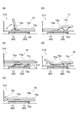
図1(a)〜図1(c)は、第1実施形態に係る電動家具を例示する模式的斜視図である。
図1(a)に示すように、第1実施形態に係る電動家具310は、被制御部70Cを含む。被制御部70Cは、例えば、可動部70を含む。被制御部70Cは、可動部70、照明部73a及び温度制御部73b(例えばヒータなど)の少なくともいずれかを含んでも良い。この例では、電動家具310には、制御装置160が設けられている。制御装置160は、電動家具310の可動部70を制御することができる。制御装置160は、例えば、電動家具310のリモートコントローラ(リモコン)である。制御装置160は、例えば、手元スイッチである。制御装置160は、照明の入り切り機能、看護者または介護者の呼び出し機能、または、電源の入り切り機能などの種々の機能を有しても良い。
(First Embodiment)
1 (a) to 1 (c) are schematic perspective views illustrating the electric furniture according to the first embodiment.
As shown in FIG. 1A, the
電動家具310は、例えば、病院、介護施設、または、家庭などで使用される。
The
この例では、電動家具310は、電動ベッドである。電動ベッドは、可動部70を有する。可動部70は、例えば、背ボトム70a、膝ボトム70b、脚ボトム70c及び高さ変更部70d(例えばベッド昇降機)などを含む。背ボトム70a、膝ボトム70b及び脚ボトム70cにおいて、互いの角度は変更可能である。背ボトム70aの動作により、使用者の背の角度が変更可能である。膝ボトム70bと脚ボトム70cとの間の角度の変更により、膝の角度が変更可能である。これらの角度は、連動して変化しても良い。高さ変更部70dは、例えば、床面とベッド面との間の距離(高さ)を変更可能である。高さ変更部70dは、ベッドの頭側の高さと、ベッドの足側の高さと、独立して変更できても良い。これにより、ベッド面の全体の傾斜が変更できる。これらの可動部70には、例えばアクチュエータなどが用いられる。可動部70の動作により、「背上げ」、「膝上げ」、「高さ調整」及び「傾斜」などの少なくともいずれかが可能である。「傾斜」は、ローリング及びチルトの少なくともいずれかを含む。
In this example, the
制御装置160は、上記の可動部70と電気的に接続される。制御装置160と可動部70との間に、制御回路が設けられても良い。このように、間に他の回路が設けられる場合も、電気的に接続される状態に含まれる。
The
図1(a)に示すように、制御装置160は、ケーブル15により、電動家具310と接続される。制御装置160は、無線通信により、電動家具310と接続されても良い。制御装置160は、操作部10を含む。
As shown in FIG. 1A, the
図1(b)及び図1(c)に示すように、制御装置160(操作部10)は、第1面10a及び第2面10bを有する。第2面10bは、第1面10aと反対側の面である。第1面10aは、例えば、表側の面である。第2面10bは、例えば、裏面である。第1面10aは、例えば、操作面である。
As shown in FIGS. 1 (b) and 1 (c), the control device 160 (operation unit 10) has a
制御装置160は、第1操作受付部20(例えば複数の操作ボタン)と、第2操作受付部25(例えばメモリーボタン)と、スイッチ50と、を含む。
The
第1操作受付部20(例えば複数の操作ボタン)及び第2操作受付部25(例えばメモリーボタン)は、第1面10aに設けられる。スイッチ50は、例えば、第1面10a以外の部分に設けられる。この例では、スイッチ50は、第2面10bに設けられている。スイッチ50は、制御装置160の筐体の側面に設けられても良い。
The first operation reception unit 20 (for example, a plurality of operation buttons) and the second operation reception unit 25 (for example, a memory button) are provided on the
第1操作受付部20、及び、第2操作受付部25には、例えば、機械的な接点を有するスイッチ(例えばボタン)が用いられる。第1操作受付部20、及び、第2操作受付部25には、この他、静電式または光学式などの任意の入力装置(例えばタッチスイッチなど)が用いられても良い。
For the first
第1操作受付部20(例えば、複数の操作ボタン)及び第2操作受付部25(例えばメモリーボタン)は、電動家具310の可動部70の動作を制御する制御操作を受け付け可能である。
The first operation reception unit 20 (for example, a plurality of operation buttons) and the second operation reception unit 25 (for example, a memory button) can accept control operations for controlling the operation of the
第1操作受付部20及び第2操作受付部25が受け付けた制御操作に基づいて、可動部70が制御される。第1操作受付部20が操作されることで、可動部70が操作される。第2操作受付部25が操作されることで、可動部70は、記憶された状態になる。記憶された状態は、例えば、記憶部48(図1(a)参照)に記憶されている。
The
この例では、第1操作受付部20(例えば複数の操作ボタン)は、「連動」に関する上昇のボタン21a、「連動」に関する下降のボタン21b、「頭」に関する上昇のボタン22a、「頭」に関する下降のボタン22b、「足」に関する上昇のボタン23a、「足」に関する下降のボタン23b、「高さ」に関する上昇降のボタン24a、及び、「高さ」に関する下降のボタン24bなどを含む。
In this example, the first operation receiving unit 20 (for example, a plurality of operation buttons) relates to an
例えば、「頭」に関する上昇のボタン22aが押されると、背ボトム70aの角度が大きくなる。例えば、「頭」に関する下降のボタン22bが押されると、背ボトム70aの角度が小さくなる。例えば、「足」に関する上昇のボタン23aが押されると、膝ボトム70b及び脚ボトム70cの角度が大きくなる。例えば、「足」に関する下降のボタン23bが押されると、膝ボトム70b及び脚ボトム70cの角度が小さくなる。これらの角度は、例えば、水平面からの角度である。例えば、「高さ」に関する上昇のボタン24aが押されると、ベッド面が高くなる。例えば、「高さ」に関する下降のボタン24bが押されると、ベッド面が低くなる。例えば、「連動」に関する上昇のボタン21aが押されると、「頭」及び「足」が連動して変化する。例えば、「連動」に関する下降のボタン21bが押されると、「頭」及び「足」が連動して変化する。これらの変化は、可動部70の動作により行われる。例えば、第1操作受付部20が操作を受け続けている期間(例えば操作ボタンを押し続けている期間)に、上記の動作が行われる。これにより、安全な動作が得られる。
For example, when the
この例では、第2操作受付部25として、複数のボタン(第1メモリーポジションに関するボタン25a、及び、第2メモリーポジションに関するボタン25bなど)が設けられている。第2操作受付部25となる複数のボタンの数は、3以上でも良い。
In this example, a plurality of buttons (
ボタン25aが押されると、第1メモリーポジションが形成される。ボタン25bが押されると、第2メモリーポジションが形成される。第1メモリーポジションは、背ボトム70a、膝ボトム70b、脚ボトム70c及び高さ変更部70dのそれぞれの状態の組み合わせの1つの状態に対応する。第2メモリーポジションは、背ボトム70a、膝ボトム70b、脚ボトム70c及び高さ変更部70dのそれぞれの状態の組み合わせの別の1つの状態に対応する。
When the
第2操作受付部25(ボタン25a及びボタン25b)により、所望の姿勢が形成できる。この所望の姿勢は、記憶部48に記憶されている。さらに、所望の姿勢に至るまでの可動部70の動きの順番も記憶されていても良い。記憶された順番に従って、可動部70が動く。
A desired posture can be formed by the second operation reception unit 25 (
第2操作受付部25(例えばメモリーボタン)による可動部70の制御は、第1操作受付部20(例えば複数の操作ボタン)よる可動部70の制御よりも簡単である。第2操作受付部25(例えばメモリーボタン)により、使い易さが向上する。
The control of the
第2操作受付部25(例えばメモリーボタン)は、例えば、電動家具310の使用者により操作されるのに適している。さらに、第2操作受付部25は、電動家具310の使用者の介護者(看護師など)により、操作されても良い。
The second operation receiving unit 25 (for example, a memory button) is suitable for being operated by, for example, a user of the
一方、複数の第1操作受付部20(例えば複数の操作ボタン)の少なくとも一部は、複数の可動部70のそれぞれを個別に独立して制御することができる。これにより、所望の状態が、細かく制御できる。従って、複数の第1操作受付部20は、介護者(看護師など)により操作されるのに適している。
On the other hand, at least a part of the plurality of first operation receiving units 20 (for example, a plurality of operation buttons) can individually and independently control each of the plurality of
第2操作受付部25(例えばメモリーボタン)を設けることで、電動家具310(例えば電動ベッド)の使用者に、可動部70をより積極的に動かすことを促すことができる。第1操作受付部20に加えて、第2操作受付部25を設けることで、例えば、使用者と、使用者の介護者と、の両方において、より使い易くなる。
By providing the second operation reception unit 25 (for example, a memory button), it is possible to encourage the user of the electric furniture 310 (for example, an electric bed) to move the
可動部70の状態の記憶部48への記憶は、自動的に行われても良い。または、可動部70の状態の記憶部48への記憶は、手動で行われても良い。可動部70の状態を手動で記憶する際などに、例えば、スイッチ50が用いられる。
The state of the
例えば、制御装置160において、操作モードと記憶モードが設けられても良い。スイッチ50の操作により、これらのモードが切り替えられても良い。例えば、操作モードにおいて、第1操作受付部20及び第2操作受付部25を操作することで、可動部70が操作される。スイッチ50を操作することで、記憶モードに移行することができる。この記憶モードにおいて第1操作受付部20を操作することで、可動部70が所望の状態となる。例えば、この状態で、第2操作受付部25(ボタン25aまたはボタン25b)を押すことで、そのときの可動部70の状態が、記憶部48に記憶される。スイッチ50を再度押すことで、操作モードに戻る。操作モードにおいて、第2操作受付部25を操作することで、記憶された可動部70の状態が形成される。このように、実施形態において、スイッチ50を用いて、可動部70の状態が記憶されても良い。
For example, the
スイッチ50は、上記のようなモードの切り替えの他、任意の制御に用いられても良い。スイッチ50としては、例えば、ハードウエアスイッチ、または、ソフトウエア制御されるスイッチなどを用いることができる。
The
一方、可動部70の状態の記憶部48への記憶が自動的に行われる場合は、例えば、検出部(後述)により、電動家具310の使用者の状態が検出される。検出部は、電動家具310内に設けられても良く、電動家具310とは別に設けられても良い。そして、検出された使用者の状態が所定の状態かどうかが判断(推定)される。所定の状態は、例えば、起き上がり、端座位(例えば離床準備状態)、離床、入眠、睡眠、または覚醒(ただしベッド70上に横たわっている)などである。使用者の状態が所定の状態であると判断(推定)されたときに、そのときの可動部70の状態が、記憶部48に記憶される。このとき、第2操作受付部25(例えばメモリーボタン)が操作を受け付けると(例えばメモリーボタンが押されると)、記憶部48に自動的に記憶された可動部70の状態が形成される。
On the other hand, when the state of the
実施形態においては、検出部により検出された使用者の状態に基づいて可動部70が自動的に(手動ではなく)動く。
In the embodiment, the
例えば、上記のように、第1操作受付部20または第2操作受付部25が制御操作を受け付けると可動部70が動く。これは、手動動作である。実施形態においては、第1操作受付部20または第2操作受付部25が制御操作を受け付けなくても、検出部により検出された使用者の状態に基づいて、可動部70が動く。すなわち、電動家具310に制御部42(図1(a)参照)が設けられる。制御部42は、検出部により検出された使用者の状態に基づいて被制御部70C(この例では、可動部70)を制御する。すなわち、制御部42は、検出部により検出された使用者の状態に基づいて可動部70を動かす「可動部制御」が可能である。これにより、操作がより簡単になる。使い易さを向上できる電動家具が提供できる。
For example, as described above, when the first
実施形態における可動部70の上記の自動的な動作は、自動モードである。例えば、スイッチ50により、上記の操作モード及び記憶モードの他に、この自動モードの実行が可能でも良い。例えば、使用者の健康状態などに応じて、自動モードの実施と不実施とが切り替えられても良い。自動モードの例については、後述する。
The above-mentioned automatic operation of the
記憶部48として、例えば、半導体記憶装置、磁気記憶装置または光学記憶装置などの任意の記憶装置を用いることができる。記憶部48は、電動家具310が設けられる場所とは異なる場所に設けられても良い。例えば、電動家具310(制御装置160を含む)と通信可能なサーバに設けられる記憶装置を、記憶部48として用いても良い。
As the
記憶部48は、例えば、制御部42(例えばコンピュータ)を介して、制御装置160と接続される。制御部42は、制御装置160に設けられても良く。制御装置160とは別に設けられても良い。
The
図1(b)に示すように、第1面10aに表示領域28が設けられても良い。表示領域28は、例えば、電動家具310の可動部70に関する情報(ボトムの角度や高さなど)を表示可能である。表示領域28は、第1操作受付部20(複数の操作ボタン)及び第2操作受付部25の、機能または動作状態に関する情報を表示しても良い。
As shown in FIG. 1B, a
以下、第1操作受付部20(例えば操作ボタン)による可動部70の制御の例について説明する。
Hereinafter, an example of control of the
図2(a)〜図2(e)は、第1実施形態に係る電動家具の制御を例示する模式図である。
図2(a)に示すように、「頭」に関するボタン22aまたはボタン22bが操作されると、背ボトム70aの角度が変化し、「背上げ動作」、または、「背下げ動作」が行われる。
2 (a) to 2 (e) are schematic views illustrating the control of the electric furniture according to the first embodiment.
As shown in FIG. 2A, when the
図2(b)に示すように、「足」に関するボタン23aまたはボタン23bが操作されると、膝ボトム70b及び脚ボトム70cの角度が変化し、「膝上げ動作」、または、「膝下げ動作」が行われる。
As shown in FIG. 2B, when the
図2(c)に示すように、「高さ」に関するボタン24a及びボタン24bが操作されると、高さ変更部70dの動きが制御される。これにより、高さ調整が行われる。すなわち、ベッド面の高さH1が変更される。
As shown in FIG. 2C, when the
図2(d)に示すように、「連動」に関するボタン21a及びボタン21bが操作されると、背ボトム70a、膝ボトム70b及び脚ボトム70cのそれぞれの角度が連動して変化する。高さH1が連動して変化しても良い。
As shown in FIG. 2D, when the
図2(e)に示すように、頭ボトム70hがさらに設けられても良い。頭ボトム70hの動作により、頭の角度が変更可能である。
As shown in FIG. 2E, a
一方、第2操作受付部25が操作を受けると(例えば、ボタン25aまたはボタン25bが操作されると)、第1メモリーポジション(第1姿勢)が形成される。この第1メモリーポジションは、背ボトム70a、膝ボトム70b、脚ボトム70c及び高さ変更部70dのそれぞれの状態の1つの組み合わせである。例えば、第2操作受付部25が操作を受けると、背ボトム70a、膝ボトム70b、脚ボトム70c及び高さ変更部70dが、記憶された順番に従って動いても良い。第2操作受付部25(ボタン25aまたはボタン25b)の操作により、頭ボトム70hがさらに制御されても良い。この場合も、頭ボトム70hの動きの順番が記憶されても良い。
On the other hand, when the second
例えば、「背上げ」、「膝上げ」、及び「高さ調整」及び「傾斜」などの少なくともいずれかに関する状態、及び、動作の順番に関する情報が記憶される。例えば、その記憶に基づいて、「背上げ」、「膝上げ」、及び「高さ調整」及び「傾斜」などの少なくともいずれかに関して、可動部70が制御される。「傾斜」は、ローリング及びチルトの少なくともいずれかを含む。
For example, information regarding at least one of "back-raising", "knee-raising", and "height adjustment" and "tilt", and the order of movements is stored. For example, based on that memory, the
図2(a)〜図2(e)に示すように、電動家具310に駆動部72(例えばアクチュエータ)が設けられる。駆動部72の動作により可動部70が動く。
As shown in FIGS. 2A to 2E, the
この例では、駆動部72は、荷重センサを含む。荷重センサ(駆動部72)に加わる荷重により、電動家具310の使用者の状態を検出することができる。例えば、電動家具310の上半身に対応する部分(例えば、背ボトム70a)に加わる荷重、及び、下半身に対応する部分(例えば、膝ボトム70b及び脚ボトム70c)に加わる荷重などに基づいて、使用者が、起き上がり、端座位、離床、入眠、睡眠、または覚醒などのそれぞれの状態であることが推定できる。
In this example, the
この例は、可動部70を駆動する駆動部72に、検出部60が設けられていることに対応する。このように、検出部60は、駆動部72に含まれても良い。
This example corresponds to the case where the
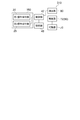
図3は、第1実施形態に係る電動家具を例示するブロック図である。
図3に示すように、制御装置160に、上記の第1操作受付部20及び第2操作受付部25が設けられる。第1操作受付部20及び第2操作受付部25は、制御部42と接続される。記憶部48及び駆動部72が、制御部42と接続される。可動部70は、駆動部72により駆動される。既に説明したように、駆動部72(例えばアクチュエータ)が荷重センサを含む場合、駆動部72の少なくとも一部が検出部60と見なされる。後述するように、検出部60は、駆動部72とは別に設けられても良い。
FIG. 3 is a block diagram illustrating the electric furniture according to the first embodiment.
As shown in FIG. 3, the
例えば、電動家具310の使用者またはその介護者が第1操作受付部20を操作する。第1操作受付部20が受け付けた操作に対応した信号が、制御部42を介して、駆動部72に供給される。信号を受けた駆動部72が可動部70を駆動することで、可動部70が動く。
For example, the user of the
記憶部48に、使用者状態情報及び可動部情報が記憶されている。使用者状態情報は、使用者の状態に関する情報(例えばデータベース)である。可動部情報は、可動部の状態に関する情報(例えばデータベース)である。可動部情報は、使用者状態情報に対応づけられている。例えば、1つの使用者状態情報に対応して、1つの可動部情報(可動部70の1つの状態に関する方向)が記憶されている。
User state information and movable unit information are stored in the
制御部42は、必要に応じて、記憶部48に記憶されている情報を取り出して処理を行う。例えば、使用者の状態の判断(推定)は、記憶部48に記憶されている使用者状態情報を用いて行われる。使用者の状態が特定の状態であると判断(推定)されたときの、可動部70の制御(「可動部制御」)は、記憶部48に記憶されている可動部情報に基づいて行われる。既に説明したように、可動部情報は、例えば、手動または自動で記憶部48に記憶される。
The
一方、例えば、検出部60(この例では駆動部72)により、使用者の状態が検出される。検出部60で検出された使用者の状態に対応する信号が、制御部42に供給される。検出された使用者の状態が、所定の状態であるかどうかが、制御部42で判断(推定)される。例えば、検出部60で検出された使用者の状態が所定の状態である場合、制御部42は、記憶部48に記憶された可動部情報に基づいて可動部70を動かす。例えば、使用者の状態が所定の状態(例えば、睡眠など)であると判断されると、可動部70が睡眠に適した状態に向けて動く。
On the other hand, for example, the detection unit 60 (driving
例えば、使用者の状態が睡眠である場合、ベッド面が高いと使用者がベッド面から落下すると危険である。使用者の状態が睡眠である場合に、ベッド面を低くすることで、使用者はより安全になる。 For example, when the user's condition is sleeping, it is dangerous if the user falls off the bed surface if the bed surface is high. When the user's condition is sleep, lowering the bed surface makes the user safer.
例えば、多くの患者(または非介護者)を収容している病院などの施設がある。このような施設において、睡眠時の安全を確保するためにベッド面を低くする作業を、看護師または介護者が行うと、非常に大きな労力となる。 For example, there are facilities such as hospitals that accommodate many patients (or non-caregivers). In such facilities, it would be a great effort for a nurse or caregiver to lower the bed surface to ensure sleep safety.
実施形態においては、例えば、使用者の状態が睡眠であるときに、それを判断して、ベッド面が自動で低くなる。これにより、看護師または介護者の負担が軽減する。 In the embodiment, for example, when the state of the user is sleep, it is determined that the bed surface is automatically lowered. This reduces the burden on the nurse or caregiver.
実施形態において判断される使用者の状態の例については、後述する。 An example of the state of the user determined in the embodiment will be described later.
図3に例示したブロック図は、機能ブロックを例示している。複数の機能が1つの回路で実施されても良い。例えば、制御部42の少なくとも一部機能が、検出部60で実施されても良い。
The block diagram illustrated in FIG. 3 illustrates a functional block. A plurality of functions may be performed in one circuit. For example, at least a part of the functions of the
使用者の状態の検出は、検出部60で行われる。検出された状態が所定の状態であるかどうかの判断(推定)は、例えば、制御部42で行われる。検出された状態が所定の状態であるかどうかの判断(推定)の少なくとも一部は、検出部60及び記憶部48の少なくとも一部で行われても良い。
The
検出部60(例えば、駆動部72である荷重センサ付きアクチュエータ)により、使用者の状態が検出される。そして、検出結果が特定の状態かどうかが判断される。 The state of the user is detected by the detection unit 60 (for example, the actuator with a load sensor which is the drive unit 72). Then, it is determined whether the detection result is in a specific state.
電動家具310が、電動ベッドの場合、この特定の状態は、例えば、起き上がり、端座位、離床、入眠、睡眠、及び覚醒などの1つである。例えば、検出部60が、荷重センサ付きの複数のアクチュエータである場合、複数の荷重センサのそれぞれに加わる荷重から、使用者が、起き上がり、端座位、離床、入眠、睡眠、覚醒などのいずれかの状態であることが判断(推定)できる。
When the
例えば、加重の変化(減少量)を基に、端座位または離床が判別される。例えば、電動ベッドの上半身に対応する部分における荷重と、下半身に対応する部分における荷重と、の差などから、「起き上がり」であると、推定できる。電動ベッドの側方の一部の荷重が局部的に大きい場合は、端座位であると推定される。電動ベッドのいずれの場所においても荷重が小さい場合は、離床であると推定される。複数の荷重センサに比較的同じような荷重が加わる場合は、入眠または睡眠であると推定できる。後述するように、検出部60として、各種の構成(例えば生体信号などの検出器など)を用いることができ、これにより、使用者における種々の状態が推定できる。
For example, the sitting position or getting out of bed is determined based on the change in weight (decrease amount). For example, it can be estimated to be "getting up" from the difference between the load in the portion corresponding to the upper body of the electric bed and the load in the portion corresponding to the lower body. If a part of the load on the side of the electric bed is locally large, it is presumed to be in the sitting position. If the load is small at any location on the electric bed, it is presumed to be out of bed. If relatively similar loads are applied to multiple load sensors, it can be presumed to fall asleep or sleep. As will be described later, various configurations (for example, a detector such as a biological signal) can be used as the
このように、使用者の状態は、複数の状態に分類されて判断(推定)されても良い。状態の分類の数は、例えば、n(nは2以上の整数)である。例えば、検出部60で検出された使用者の状態が、第1〜第n使用者状態であるかどうかが判断(推定)される。第1〜第n使用者状態のそれぞれは、例えば、起き上がり、端座位、離床、入眠、睡眠及び覚醒などのいずれかである。
In this way, the user's state may be classified into a plurality of states and judged (estimated). The number of state classifications is, for example, n (n is an integer greater than or equal to 2). For example, it is determined (estimated) whether or not the state of the user detected by the
例えば、使用者の状態が起き上がりであると判断された場合、背ボトム70aは、起き上がりに適した所定の角度となる。例えば、使用者の状態が離床であると判断(推定)された場合は、高さ変更部70dは、離床に適した所定の高さとなる。例えば、使用者の状態が睡眠であると判断(推定)された場合には、例えば、高さ変更部70dは、ベッド面から使用者が落ちても安全な低さとなる。使用者の状態が端座位の場合は、例えば、高さ変更部70dは、立ち上がりに適した所定の高さとなる。このような可動部70の制御は、制御部42の制御により駆動部72が制御されて行われる。
For example, when it is determined that the user's condition is rising, the
実施形態において、使用者の状態は、起き上がり、端座位、離床、入眠、睡眠、及び覚醒などの他、任意の状態でも良い。 In the embodiment, the state of the user may be any state other than getting up, sitting on the edge, getting out of bed, falling asleep, sleeping, and awakening.
実施形態において、記憶部48に記憶された可動部状態の少なくとも一部は、初期化(初期値に設定)可能でも良い。記憶されたデータは、一括または個別に初期化されても良い。例えば、第2操作受付部25の操作により形成される可動部70の状態が記憶部48に記憶される場合、この記憶が、一括または個別に初期化されても良い。
In the embodiment, at least a part of the movable part state stored in the
以下、記憶部48に記憶された可動部70の状態に基づいて形成される、可動部70の状態(すなわち、電動家具310の状態)のいくつかの例について説明する。
Hereinafter, some examples of the state of the movable portion 70 (that is, the state of the electric furniture 310) formed based on the state of the
図4(a)〜図4(d)は、第1実施形態に係る電動家具の状態を例示する模式図である。
これらは、電動家具310が電動ベッドであるときの例である。
図4(a)に示す例では、ベッド面の高さが低い。例えば、特に、高齢者などが使用者である場合において、使用者の状態が入眠(または睡眠)であるときにベッド面が高いと、使用者が寝ている間にベッドから落ちると危険である。ベッド面を低くすることで、より安全になる。使用者状態が睡眠であるときに、可動部70(高さ変更部70d)は、ベッド面が低いこのような状態となる。このように、制御部42は、使用者の状態が睡眠状態であるときに、高さ変更部70dの高さを下げる。ベッド面の高さは、例えば、制御可能な最低の高さとされる。
4 (a) to 4 (d) are schematic views illustrating the state of the electric furniture according to the first embodiment.
These are examples when the
In the example shown in FIG. 4A, the height of the bed surface is low. For example, especially when the elderly person is the user, if the bed surface is high when the user's condition is falling asleep (or sleeping), it is dangerous to fall off the bed while the user is sleeping. .. Lowering the bed surface makes it safer. When the user state is sleeping, the movable portion 70 (
使用者の状態が端座位であるとき、使用者は立ち上がろうとしている場合がある。このような場合に、可動部70(高さ変更部70d)の動きにより、ベッド面は、特定の高さ(端座位高さ)となる。端座位高さは、制御可能な最低の高さよりも高い。使用者の体格などに応じて端座位高さが調整可能でも良い。例えば、記憶部モードとした上で第1操作受付部20が操作されて適切な高さが調整され、その高さが端座位高さとして、記憶部48に記憶されても良い。記憶部48からそのデータが読み出されて、可動部70(高さ変更部70d)が端座位高さに調整される。このように、制御部42は、使用者の状態が端座位であるときに、高さ変更部70dの高さを端座位高さに調整しても良い。
When the user is in the sitting position, the user may be trying to stand up. In such a case, the movement of the movable portion 70 (
図4(b)に示すように、検出部60により検出された使用者の状態が入眠である場合、まず、背ボトム70aを傾斜させる。この後、検出部60により検出された使用者の状態が睡眠となった場合に、背ボトム70aの傾斜を小さくして水平に近づける。使用者の状態が入眠であるときに形成される背ボトム70aの角度(水平方向からの角度)は、例えば、4度以上24度未満である。このような角度において、覚醒状態から睡眠状態に移行し易い。すなわち、入眠が円滑に行われ、睡眠状態に速やかに移行できる。これにより、使用者において、快適で自然な入眠及び睡眠が誘起される。
As shown in FIG. 4B, when the state of the user detected by the
このように、制御部42は、検出部60で検出された使用者の状態が入眠であるときに背ボトム70aを傾斜させる。制御部42は、検出部60で検出された使用者の状態が入眠の後の睡眠であるときに、背ボトム70aを水平に向かって変化させる。上記の背ボトムの傾斜の角度は、例えば、4度以上24度未満であることが好ましい。そして、制御部42は、使用者の状態が入眠の後の睡眠であるときに、背ボトム70aの角度を4度未満にするこることか好ましい。これにより、良好な睡眠姿勢が得られる。
In this way, the
図4(c)に示す例では、背ボトム70aの角度が大きく、膝ボトム70b及び脚ボトム70cの角度は中程度であり、ベッド面は高い。例えば、使用者の状態が起き上がりであるときに、このような姿勢が形成される。例えば、テレビジョンなどをみるときなどに、このような姿勢が好まれる。制御部42は、検出部60で検出された使用者の状態が起き上がりのときに、背ボトム70aの角度を大きくする。制御部42は、さらに、膝ボトム70b、脚ボトム70c及び高さ変更部70dを動作させても良い。
In the example shown in FIG. 4C, the angle of the
図4(c)に例示した姿勢は、電動家具310で形成される姿勢の1つである。このような1つの姿勢が長時間連続すると、体に負担が生じる場合がある。例えば、「床ずれ」などの症状が生じる。このようなときに、制御部42は、姿勢を適宜変更しても良い。
The posture illustrated in FIG. 4C is one of the postures formed by the
例えば、図4(d)に示す例では、背ボトム70a、膝ボトム70b及び脚ボトム70cの角度は中程度であり、ベッド面は高い。例えば、図4(c)に示すような姿勢が一定以上続き、この期間、使用者の身体の状態が余り変化しない場合、図4(d)に示すような姿勢に移行しても良い。そして、図4(d)の姿勢の後に、再度、図4(c)に示すような姿勢が形成されても良い。
For example, in the example shown in FIG. 4D, the angles of the
実施形態において、例えば、可動部70が自動で動くときの可動部70の速度は、可動部70が手動で動くときの可動部70の速度とは異なっても良い。例えば、可動部70が自動で動くときの可動部70の速度は、可動部70が手動で動くときの可動部70の速度よりも遅くても良い。例えば、自動で姿勢が変化する場合に、その変化の速度が速いと、危険な状態が生じる可能性がある。例えば、姿勢の変化が過度に速い場合、電動家具310のフレーム(サイドレールまたはグリップなどを含む)などの間に使用者の体が挟まれる状態が生じる可能性がある。さらに、姿勢の変化が過度に速い場合、使用者が驚く。可動部70が自動で動くときの可動部70の速度を遅くすることで、より安全になり、使用者に安心を提供である。
In the embodiment, for example, the speed of the
例えば、上記のように、操作受付部(第1操作受付部20など)を含む制御装置160が、電動家具310に設けられる。既に説明したように、可動部70は、操作受付部(第1操作受付部20)が受け付けた制御操作に応じて動く。このとき、例えば、検出部60により検出された使用者の状態に基づいて可動部70が動くときの速度は、操作受付部が受け付けた制御操作に応じて可動部70が動くときの速度とは異なる。これらの速度の少なくとも一方が、変更可能(設定可能)でも良い。このような速度の変更の制御は、例えば、制御部42により行われる。
For example, as described above, the
例えば、検出部60により検出された使用者の状態は、ベッド(電動家具310)の上に人(例えば使用者など)がいない場合を含んでも良い。ベッドの上に人(例えば使用者など)がいない場合に可動部70が動くときの速度は、操作受付部が受け付けた制御操作に応じて可動部70が動くときの速度とは異なっても良い。ベッドの上に人(例えば使用者など)がいない場合に可動部70が動くときの速度は、操作受付部が受け付けた制御操作に応じて可動部70が動くときの速度よりも速くても良い。
For example, the state of the user detected by the
上記のように、実施形態においては、検出部60により検出された使用者の状態に基づいて、可動部70が自動的に(手動ではなく)動く。このとき、自動で動く可動部70などに使用者が挟まれると危険である。このため、例えば、以下のような安全を確保する手段が設けられても良い。
As described above, in the embodiment, the
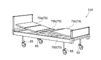
図5は、第1実施形態に係る電動家具を例示する模式的斜視図である。
図5に示すように、電動家具310は、床部検知器65を含む。床部検知器65は、可動部70と、床(電動家具310が設置されている床)と、の間の空間に存在する物体を検知する。床部検知器65には、例えば、赤外線センサまたは超音波センサなどが用いられる。
FIG. 5 is a schematic perspective view illustrating the electric furniture according to the first embodiment.
As shown in FIG. 5, the
例えば、電動家具310のベッド面の下に、使用者または介護者などの身体(足など)がある場合、その身体が、床部検知器65により検知される。床部検知器65の出力信号が制御部42(図5では省略)に供給される。
For example, when there is a body (feet or the like) such as a user or a caregiver under the bed surface of the
床部検知器65が可動部70と床との間の空間に存在する物体(身体など)を検知したときは、制御部42は、上記の「可動部制御」を実施しない。既に説明したように、「可動部制御」は、検出部60により検出された使用者の状態に基づいて可動部70が動かされる制御である。物体(身体など)が検知されたときは、例えば、可動部70が動かない。または、上記の「可動部制御」とは異なる制御が行われる。例えば、可動部70の動きの幅(距離)が、上記の「可動部制御」のときの動きの幅(距離)よりも小さい。これにより、不安全に可動部70が動くことが抑制できる。
When the
図6は、第1実施形態に係る電動家具を例示する模式的斜視図である。
図6に示すように、電動家具310には、フレーム75(サイドレールまたはグリップなどを含む)が設けられている。フレーム75が設けられることで、電動家具310(この例では電動ベッド)に寝ている使用者が電動ベッドから落ちることが抑制できる。
FIG. 6 is a schematic perspective view illustrating the electric furniture according to the first embodiment.
As shown in FIG. 6, the
電動家具310は、フレーム部検知器66を含む。フレーム部検知器66は、フレーム75と可動部70との間の空間に存在する物体を検知する。この物体は、例えば、使用者または介護者の身体を含む。フレーム部検知器66には、例えば、赤外線センサまたは超音波センサなどが用いられる。フレーム部検知器66は、アクチュエータ(可動部70)が受ける過負荷を検知しても良い。例えば、フレーム75などに物体が挟まったときに、アクチュエータに加わる負荷が過度に大きくなる場合がある。過負荷を検知することで、物体が挟まれることを検知できる。フレーム部検知器66の出力信号が制御部42(図6では省略)に供給される。
The
フレーム部検知器66がフレーム75と可動部70との間の空間に存在する物体を検知したときは、制御部42は、上記の「可動部制御」を実施しない。物体(身体など)が検知されたときは、例えば、可動部70が動かない。または、上記の「可動部制御」とは異なる制御が行われる。例えば、可動部70の動きの幅(距離)が、上記の「可動部制御」のときの動きの幅(距離)よりも小さい。これにより、不安全に可動部70が動くことが抑制できる。
When the
例えば、床部検知器65、または、フレーム部検知器66が物体(身体など)を検知したときに、警報(音、振動、または、表示など)が発生されても良い。これにより、可動部70が動かない原因が特定でき、使用者または介護者などがその原因を除去できる。
For example, when the
(第2実施形態)
図7は、第2実施形態に係る電動家具を例示する模式的斜視図である。
図7に示すように、本実施形態に係る電動家具320も、可動部70、検出部60及び制御部42を含む。この例においても、検出部60は、使用者の状態を検出する。制御部42は、検出部60により検出された使用者の状態に基づいて可動部70を動かす可動部制御が可能である。本実施形態においては、検出部60として、身体検知器63が設けられる。身体検知器63は、使用者の身体の位置を検出できる。身体検知器63として、例えば、画像センサ(例えばカメラ)などを用いることができる。画像センサは、使用者、電動家具320、及び、その周囲の画像を取得する。この画像に基づいて、使用者の身体の位置と、電動家具320の位置と、の相対的な関係を検知できる。身体検知器63の検知結果(出力信号)が制御部42に供給される。
(Second Embodiment)
FIG. 7 is a schematic perspective view illustrating the electric furniture according to the second embodiment.
As shown in FIG. 7, the
身体検知器63が、身体の少なくとも一部が電動家具320と重なることを検知したときは、上記の「可動部制御」を実施しない。例えば、可動部70が動かない。または、上記の「可動部制御」とは異なる制御が行われる。例えば、身体の少なくとも一部が電動家具320と重なることを検知したときの可動部70の動きの幅(距離)は、上記の「可動部制御」のときの動きの幅(距離)よりも小さい。これにより、不安全に可動部70が動くことが抑制できる。
When the
例えば、身体検知器63が身体と電動家具320との重なりを検知したときに、警報(音、振動、または、表示など)が発生されても良い。これにより、可動部70が動かない原因が特定でき、使用者または介護者などがその原因を除去できる。
For example, when the
身体検知器63(画像センサ)の検知結果に基づいて、使用者の状態を判断(推定)することもできる。この場合は、身体検知器63は、検出部60の少なくとも一部となる。
It is also possible to judge (estimate) the state of the user based on the detection result of the body detector 63 (image sensor). In this case, the
図7には、検出部60の他の例も示されている。
図7に示すように、電動家具320にシート型の離床センサ61が設けられても良い。例えば、電動家具320(この例では電動ベッド)の使用者が、電動ベッドから起き上がり離床センサ61の上に乗ると、使用者の体重が離床センサ61に加わる。離床センサ61は、体重による荷重を検出する。これにより、離床センサ61は、離床を検出できる。
FIG. 7 also shows another example of the
As shown in FIG. 7, the
電動家具320において、電動ベッドにセンサ62が設けられても良い。センサ62が荷重(圧力)を検出可能である場合、電動ベッドの複数の箇所のそれぞれにセンサ62が設けられても良い。電動ベッドの使用者の体重(荷重)が、センサ62により検出される。これにより、センサ62は、使用者の種々の状態を検出(推定)できる。
In the
センサ62は、使用者の脈拍、呼吸及び体温の少なくともいずれかを検出可能でも良い。これらの値及びその変化により、使用者の状態を検出(推定)できる。
The
離床センサ61、センサ62及び身体検知器63(画像センサ)は、検出部60の例である。検出部60は、種々の変形が可能である。
The
以下、センサ62のいくつかの例について説明する。
Hereinafter, some examples of the
図8(a)及び図8(b)は、第2実施形態に係る電動家具を例示する模式図である。 図8(a)は、センサ62、及び、センサ62の配置を例示する模式的斜視図である。図8(b)は、センサ62を例示する模式的平面図である。図8(a)においては、図を見やすくするために、構成要素が互いに離されて描かれている。
8 (a) and 8 (b) are schematic views illustrating the electric furniture according to the second embodiment. FIG. 8A is a schematic perspective view illustrating the
図8(a)に示すように、ベッド70のベッド脚部74の上に、ボトム71が設けられる。ボトム71の上に、マットレス76が設けられる。マットレス76の上に、使用者81が横たわる。センサ62(検出部60)は、ボトム71とマットレス76との間に設けられる。この例では、センサ62は、シート状またはプレート状である。
As shown in FIG. 8A, a bottom 71 is provided on the
図8(b)に示すように、センサ62は、回路部62a及びセンサ部62bを含む。回路部62aは、通信部62cを含む。通信部62cは、制御部42とデータの送受信を行う。送受信は、有線及び無線の少なくともいずれかを含む任意の方法により行われる。
As shown in FIG. 8B, the
センサ部62bは、例えば、センサ装置62dを含む。センサ部62bは、センサ部62bが受ける力(または力に対応した特性)を検出する。力は、例えば、圧力及び音波の少なくともいずれかを含む。センサ部62bは、例えば、圧力センサを含む。センサ部62bは、例えば、マイクロフォンを含む。
The
センサ部62bに、マットレス76を介して、使用者81による力(圧力及び音波の少なくともいずれか)が加わる。例えば、センサ部62bで検出された力に基づく信号が、回路部62aから出力される。出力された信号が制御部42に供給される。制御部42において、信号(力)の大きさ及び信号(力)の大きさの時間的な変化の少なくともいずれかに基づいて、使用者81の状態(離床、睡眠、または覚醒など)が推定される。または、回路部62aにおいて、センサ部62bで検出された力及び力の時間的な変化の少なくともいずれかに基づいて、使用者81の状態(離床、睡眠、または覚醒など)が推定されても良い。使用者81の状態は、起き上がり、端座位(例えば離床準備状態)、離床、入眠、睡眠、または覚醒を含んでも良い。
A force (at least one of pressure and sound waves) by the
例えば、使用者81の状態に応じた振動が、センサ部62bに加わる。振動は、例えば、使用者81の体動に応じている。振動がセンサ部62bにおいて検出される。振動は、音を含んでも良い。
For example, vibration according to the state of the
例えば、振動検出手段(センサ部62b)と、処理部(回路部62a及び制御部42の少なくともいずれかの少なくとも一部)と、が設けられる。処理部は、例えば、コンピュータを含む。振動検出手段は、例えば、寝具(ベッド70)上の就寝者(使用者81)の振動を検出する。処理部は、例えば、活動量算出手段と、睡眠判定値算出手段と、睡眠状態判定手段と、を含む。これらの手段は、機能的に分けられている。活動量算出手段は、例えば、振動検出手段により検出された振動に基づいて、就寝者の活動量をサンプリング単位時間毎に算出する。睡眠判定値算出手段は、例えば、第1時刻(例えば、現在の時刻)の活動量と、第2時刻(例えば現在の時刻以前の時刻)に算出した活動量と、に、時間に応じて重み付けした補正係数を乗じた値の総和を睡眠判定値として算出する。睡眠状態判定手段は、例えば、睡眠判定値が所定の閾値を超えた場合には覚醒状態と判定し、それ以外の場合には睡眠状態と判定する。
For example, a vibration detecting means (
図9(a)〜図9(d)は、第2実施形態に係る別の電動家具を例示する模式図である。
図9(a)は、センサ62の例の断面図である。図9(b)は、センサ62の例の平面図である。図9(c)は、センサ62の配置を例示する斜視図である。図9(d)は、センサ62の配置を例示する側面図である。
9 (a) to 9 (d) are schematic views illustrating another electric furniture according to the second embodiment.
FIG. 9A is a cross-sectional view of an example of the
図9(a)に示すように、この例においては、センサ62は、第1板体62pと、第2板体62qと、を含む。第2板体62qは、第1板体62pと対向する。これらの板体は、シート状でも良い。
As shown in FIG. 9A, in this example, the
第2板体62qは、支持突起62sを含む。支持突起62sは、第1板体62pの外縁部に対向する。第1板体62pは、外縁部の内側の内側部を含む。内側部と、第2板体62qと、の間に、空気収容体62rが設けられる。この例では、第2板体62qに溝62tが設けられている。溝62tにより形成される空間(分けられる空間)に空気収容体62rが設けられる。空気収容体62rには、信号線62uの一端が接続される。信号線62uの他端は、検出回路62v(検出装置)に接続される。
The
図9(b)に示すように、支持突起62sは、第1板体62pの外縁の一部と対向する。この例では、支持突起62sは、第1板体62pの、4つのコーナー部に設けられている。センサ62は、シート状、または、板状である。
As shown in FIG. 9B, the
図9(c)に示すように、ボトム71の上に、上記のセンサ62が置かれる。図9(d)に示すように、ボトム71の上に、センサ62が置かれ、その上に、マットレス76が置かれる。マットレス76の上に、使用者81が横たわる。
As shown in FIG. 9C, the
例えば、使用者81の体の動きに応じた力が空気収容体62rに加わる。この力は、例えば、振動を含む。空気収容体62rに加わる力(または力に対応した特性)が検出回路62vにより検出される。例えば、空気収容体62rに、圧力検出器が設けられ、圧力検出器により得られた信号(検出結果)が、検出回路62vに供給される。例えば、空気収容体62rに、マイクロフォンが設けられ、マイクロフォンにより得られた信号(検出結果)が、検出回路62vに供給される。例えば、検出回路62vの出力(信号)が制御部42に供給される。制御部42において、使用者81の状態(離床、睡眠、または覚醒など)が推定される。または、検出回路62vにおいて、検出された力及び力の時間的な変化の少なくともいずれかに基づいて、使用者81の状態(離床、睡眠、または覚醒など)が推定されても良い。使用者81の状態は、起き上がり、端座位(例えば離床準備状態)、離床、入眠、睡眠、または覚醒を含んでも良い。
For example, a force corresponding to the movement of the body of the
センサ62は、例えば、生体情報収集装置である。センサ62において、第1板体62pは、例えば、使用者81の身体側に配置される。第2板体62qは、例えば、支持側に設けられる。第1板体62pと第2板体62qとの中央部間に、空気圧検出用の変形可能な空気収容体62rが設けられる。第2板体62qの中央部には、空気収容体62rを装着する溝62tが設けられる。支持突起62sは、第2板体62qから第1板体62pに向かう方向に、突出する。支持突起62sは、第1板体62pの周囲の四隅を支持する。支持突起62sは、例えば、第1板体62pを水平な状態(正常状態)に常時支持する。
The
実施形態において、センサ62は、種々の変形が可能である。
In the embodiment, the
実施形態において、制御部42は、検出部60により検出された使用者81の状態に基づいて、被制御部70Cとして、照明部73a及び温度制御部73bの少なくともいずれか(図1(a)参照)を制御しても良い。例えば、センサ62により検出された使用者81の状態(起き上がり、端座位(例えば離床準備状態)、離床、入眠、睡眠、及び覚醒の少なくともいずれか)に基づいて、照明部73aの明るさを変更(例えば、オン/オフを含む)しても良い。例えば、センサ62により検出された使用者81の状態に基づいて、照明部73aから出射される光の方向を変更しても良い。照明部73aは、例えば、読書灯及び脚下灯の少なくともいずれかを含む。例えば、センサ62により検出された使用者81の状態に基づいて、温度制御部73bの温度を変更(例えば、オン/オフを含む)しても良い。使い易さを向上できる電動家具を提供できる。
In the embodiment, the
(第3実施形態)
図10は、第3実施形態に係る電動家具を例示する模式的斜視図である。
図10に示すように、電動家具330は、電動椅子である。電動家具330は、可動部70を含む。可動部70は、例えば、背もたれ部70e及び座面部70fを含む。背もたれ部70eは、角度が変更可能なボトム部に対応する。座面部70fは、高さ変更部に対応する。座面部70fの角度が変更可能でも良い。実施形態に係る制御装置160により、これらの可動部70が制御される。電動家具330においても、使用者の状態に対応して、可動部70が動く。
(Third Embodiment)
FIG. 10 is a schematic perspective view illustrating the electric furniture according to the third embodiment.
As shown in FIG. 10, the
実施形態によれば、使い易さを向上できる電動家具が提供できる。 According to the embodiment, it is possible to provide electric furniture that can improve usability.
以上、具体例を参照しつつ、本発明の実施の形態について説明した。しかし、本発明は、これらの具体例に限定されるものではない。例えば、電動家具に含まれる第1操作受付部、操作ボタン、第2操作受付部、メモリーボタン、スイッチ、表示領域、検出部、可動部、駆動部、制御部及び記憶部などの各要素の具体的な構成に関しては、当業者が公知の範囲から適宜選択することにより本発明を同様に実施し、同様の効果を得ることができる限り、本発明の範囲に包含される。 The embodiments of the present invention have been described above with reference to specific examples. However, the present invention is not limited to these specific examples. For example, specific elements such as a first operation reception unit, an operation button, a second operation reception unit, a memory button, a switch, a display area, a detection unit, a movable unit, a drive unit, a control unit, and a storage unit included in electric furniture. The present invention is included in the scope of the present invention as long as the present invention can be similarly carried out and the same effect can be obtained by appropriately selecting from a range known to those skilled in the art.
各具体例のいずれか2つ以上の要素を技術的に可能な範囲で組み合わせたものも、本発明の要旨を包含する限り本発明の範囲に含まれる。 A combination of any two or more elements of each specific example to the extent technically possible is also included in the scope of the present invention as long as the gist of the present invention is included.
その他、本発明の実施形態として上述した電動家具を基にして、当業者が適宜設計変更して実施し得る全ての電動家具も、本発明の要旨を包含する限り、本発明の範囲に属する。 In addition, all electric furniture that can be appropriately designed and implemented by those skilled in the art based on the electric furniture described above as an embodiment of the present invention also belongs to the scope of the present invention as long as the gist of the present invention is included.
その他、本発明の思想の範疇において、当業者であれば、各種の変更例及び修正例に想到し得るものであり、それら変更例及び修正例についても本発明の範囲に属するものと了解される。 In addition, within the scope of the idea of the present invention, those skilled in the art can come up with various modified examples and modified examples, and it is understood that these modified examples and modified examples also belong to the scope of the present invention. ..
10…操作部、 10a、10b…第1、第2面、 15…ケーブル、 20…第1操作受付部、 21a、21b、22a、22b、23a、23b、24a、24b…ボタン、 25…第2操作受付部、 25a、25b…ボタン、 28…表示領域、 42…制御部、 48…記憶部、 50…スイッチ、 60…検出部、 61…離床センサ、 62…センサ、 62a…回路部、 62b…センサ部、 62c…通信部、 62d…センサ装置、 62p…第1板体、 62q…第2板体、 62r…空気収容体、 62s…支持突起、 62t…溝、 62u…信号線、 62v…検出回路、 63…身体検知部、 65…床部検知部、 66…フレーム部検知部、 70…可動部、 70C…被制御部、 70a…背ボトム、 70b…膝ボトム、 70c…脚ボトム、 70d…高さ変更部、 70e…背もたれ部、 70f…座面部、 70h…頭ボトム、 71…ボトム、 72…駆動部、 73a…照明部、 73b…温度制御部、 74…ベッド脚部、 75…フレーム、 76…マットレス、 81…使用者、 160…制御装置、 310、320、330…電動家具、 H1…高さ 10 ... Operation unit, 10a, 10b ... 1st, 2nd surface, 15 ... Cable, 20 ... 1st operation reception unit, 21a, 21b, 22a, 22b, 23a, 23b, 24a, 24b ... Button, 25 ... 2nd Operation reception unit, 25a, 25b ... button, 28 ... display area, 42 ... control unit, 48 ... storage unit, 50 ... switch, 60 ... detection unit, 61 ... bed leaving sensor, 62 ... sensor, 62a ... circuit unit, 62b ... Sensor unit, 62c ... Communication unit, 62d ... Sensor device, 62p ... First plate body, 62q ... Second plate body, 62r ... Air containment body, 62s ... Support protrusion, 62t ... Groove, 62u ... Signal line, 62v ... Detection Circuit, 63 ... Body detection unit, 65 ... Floor detection unit, 66 ... Frame unit detection unit, 70 ... Movable part, 70C ... Controlled unit, 70a ... Back bottom, 70b ... Knee bottom, 70c ... Leg bottom, 70d ... Height change part, 70e ... backrest part, 70f ... seat surface part, 70h ... head bottom, 71 ... bottom, 72 ... drive part, 73a ... lighting part, 73b ... temperature control part, 74 ... bed leg part, 75 ... frame, 76 ... mattress, 81 ... user, 160 ... control device, 310, 320, 330 ... electric furniture, H1 ... height
Claims (12)
使用者の状態を検出する検出部と、
前記使用者の前記状態に対応付けて自動で被制御部情報を記憶し、自動で記憶された前記被制御部情報に基づいて前記被制御部を制御する制御部と、
を備える、
電動家具。 Controlled unit and
A detector that detects the user's condition and
A control unit that automatically stores controlled unit information in association with the state of the user and controls the controlled unit based on the automatically stored controlled unit information.
Equipped with a,
Moving furniture electricity.
前記制御部は、前記検出部により検出された前記使用者の前記状態に基づいて前記可動部を動かす可動部制御を行う、請求項1記載の電動家具。 The controlled portion includes a movable portion.
Wherein the control unit performs a moving section control to move the movable unit based on the state of the user detected by the detection unit, electric furniture according to claim 1 Symbol placement.
前記制御部は、前記使用者の前記状態が睡眠状態であるときに、前記高さ変更部の高さを下げる、請求項2記載の電動家具。 The movable portion includes a height changing portion.
Wherein, when the prior SL state of the user is in sleep state, lowering the height of the height changing section, electric furniture according to claim 2, wherein.
前記検出部が検出した前記使用者の前記状態が端座位であるときに、前記制御部は、前記高さ変更部の高さを端座位高さに調整する、請求項2記載の電動家具。 The movable portion includes a height changing portion.
When the state of the user to the detecting unit detects is sitting-on-bed-edge, wherein the control unit adjusts the height of the front Kidaka of changing portion stanza position height, electric furniture according to claim 2, wherein ..
をさらに備え、
前記床部検知器が前記可動部と前記床との間の前記空間の前記物体を検知したときは、前記制御部は、前記可動部制御を実施しない、請求項2〜4のいずれか1つに記載の電動家具。 A floor detector that detects an object existing in the space between the movable part and the floor,
With more
When the floor detector detects the object in the space between the movable portion and the floor, the control unit does not perform the movable portion control, any one of claims 2 to 4. Electric furniture described in.
前記制御部は、前記使用者の前記状態が入眠であるときに、前記背ボトムを傾斜させ、
前記制御部は、前記使用者の前記状態が前記入眠の後の睡眠であるときに、前記背ボトムを水平に向かって変化させる、請求項2〜5のいずれか1つに記載の電動家具。 The movable part includes a back bottom
The control unit tilts the back bottom when the user is in a sleep state.
The electric furniture according to any one of claims 2 to 5 , wherein the control unit changes the back bottom horizontally when the state of the user is sleep after falling asleep.
前記制御部は、前記使用者の前記状態が前記入眠の後の前記睡眠であるときに、前記背ボトムの角度を4度未満にする、請求項6記載の電動家具。 The angle of inclination of the back bottom is 4 degrees or more and less than 24 degrees.
The electric furniture according to claim 6 , wherein the control unit makes the angle of the back bottom less than 4 degrees when the state of the user is the sleep after falling asleep.
前記制御部は、前記使用者の前記状態が起き上がりのときに、前記背ボトムの角度を大きくする、請求項2〜5のいずれか1つに記載の電動家具。 The movable part includes a back bottom
The electric furniture according to any one of claims 2 to 5 , wherein the control unit increases the angle of the back bottom when the user's state is raised.
前記フレームと前記可動部との間の空間に存在する物体を検知するフレーム部検知器と、
をさらに備え、
前記フレーム部検知器が前記フレームと前記可動部との間の前記空間の前記物体を検知したときは、前記制御部は、前記可動部制御を実施しない、請求項2〜8のいずれか1つに記載の電動家具。 With the frame
A frame unit detector that detects an object existing in the space between the frame and the movable unit,
With more
When the frame unit detector detects the object in the space between the frame and the movable unit, the control unit does not perform the movable unit control, any one of claims 2 to 8. Electric furniture described in.
前記身体検知器が前記身体の少なくとも一部が前記電動家具と重なることを検知したときは、前記制御部は、前記可動部制御を実施しない、請求項2〜9のいずれか1つに記載の電動家具。 Further equipped with a body detector for detecting the position of the user's body,
The method according to any one of claims 2 to 9 , wherein when the body detector detects that at least a part of the body overlaps with the electric furniture, the control unit does not control the movable part. Electric furniture.
前記可動部は、前記操作受付部が受け付けた制御操作に応じて動き、
前記検出部により検出された前記使用者の前記状態に基づいて前記可動部が自動で動くときの速度は、前記操作受付部が受け付けた前記制御操作に応じて前記可動部が動くときの速度とは異なる、請求項2〜10のいずれか1つに記載の電動家具。 Further equipped with a control device including an operation reception unit,
The movable portion moves in response to a control operation received by the operation reception unit,
The speed at which the movable portion automatically moves based on the state of the user detected by the detection unit is the speed at which the movable portion moves in response to the control operation received by the operation reception unit. Is different, the electric furniture according to any one of claims 2 to 10 .
前記制御部は、前記記憶部に記憶された可動部情報に基づいて前記可動部を自動で動かす、請求項2〜11のいずれか1つに記載の電動家具。 A storage unit that stores user state information regarding the state of the user and movable part information regarding the state of the movable part corresponding to the user state information is further provided.
The electric furniture according to any one of claims 2 to 11 , wherein the control unit automatically moves the movable unit based on the movable unit information stored in the storage unit.
Priority Applications (5)
| Application Number | Priority Date | Filing Date | Title |
|---|---|---|---|
| JP2017091077A JP6769922B2 (en) | 2017-05-01 | 2017-05-01 | Electric furniture |
| US16/482,185 US20200113760A1 (en) | 2017-05-01 | 2018-04-18 | Electric furniture |
| PCT/JP2018/015968 WO2018203476A1 (en) | 2017-05-01 | 2018-04-18 | Electric article of furniture |
| SG11201907180P SG11201907180PA (en) | 2017-05-01 | 2018-04-18 | Electric furniture |
| CN201880015743.2A CN110573123A (en) | 2017-05-01 | 2018-04-18 | Electric furniture |
Applications Claiming Priority (1)
| Application Number | Priority Date | Filing Date | Title |
|---|---|---|---|
| JP2017091077A JP6769922B2 (en) | 2017-05-01 | 2017-05-01 | Electric furniture |
Related Child Applications (1)
| Application Number | Title | Priority Date | Filing Date |
|---|---|---|---|
| JP2020159540A Division JP7125456B2 (en) | 2020-09-24 | 2020-09-24 | electric furniture |
Publications (3)
| Publication Number | Publication Date |
|---|---|
| JP2018187022A JP2018187022A (en) | 2018-11-29 |
| JP2018187022A5 JP2018187022A5 (en) | 2020-02-13 |
| JP6769922B2 true JP6769922B2 (en) | 2020-10-14 |
Family
ID=64016090
Family Applications (1)
| Application Number | Title | Priority Date | Filing Date |
|---|---|---|---|
| JP2017091077A Active JP6769922B2 (en) | 2017-05-01 | 2017-05-01 | Electric furniture |
Country Status (5)
| Country | Link |
|---|---|
| US (1) | US20200113760A1 (en) |
| JP (1) | JP6769922B2 (en) |
| CN (1) | CN110573123A (en) |
| SG (1) | SG11201907180PA (en) |
| WO (1) | WO2018203476A1 (en) |
Families Citing this family (12)
| Publication number | Priority date | Publication date | Assignee | Title |
|---|---|---|---|---|
| US11382812B2 (en) | 2017-06-27 | 2022-07-12 | Stryker Corporation | Patient support systems and methods for assisting caregivers with patient care |
| US11810667B2 (en) | 2017-06-27 | 2023-11-07 | Stryker Corporation | Patient support systems and methods for assisting caregivers with patient care |
| US10811136B2 (en) | 2017-06-27 | 2020-10-20 | Stryker Corporation | Access systems for use with patient support apparatuses |
| US11337872B2 (en) | 2017-06-27 | 2022-05-24 | Stryker Corporation | Patient support systems and methods for assisting caregivers with patient care |
| US11096850B2 (en) | 2017-06-27 | 2021-08-24 | Stryker Corporation | Patient support apparatus control systems |
| US11484451B1 (en) | 2017-06-27 | 2022-11-01 | Stryker Corporation | Patient support apparatus user interfaces |
| US11202729B2 (en) | 2017-06-27 | 2021-12-21 | Stryker Corporation | Patient support apparatus user interfaces |
| US11304865B2 (en) | 2017-06-27 | 2022-04-19 | Stryker Corporation | Patient support apparatus with adaptive user interface |
| JP7190342B2 (en) * | 2018-12-05 | 2022-12-15 | パラマウントベッド株式会社 | bed equipment |
| CN110710820A (en) * | 2019-10-25 | 2020-01-21 | 郑州大学 | Nursing bed with auxiliary getting-up structure and using method thereof |
| CN111887861B (en) * | 2020-09-30 | 2021-02-26 | 西南交通大学 | Millimeter wave radar-based integrated monitoring method for indoor personnel safety |
| CN115177465A (en) * | 2021-04-07 | 2022-10-14 | 上海尊颐智能科技有限公司 | Application of nursing bed |
Family Cites Families (14)
| Publication number | Priority date | Publication date | Assignee | Title |
|---|---|---|---|---|
| JP2874035B1 (en) * | 1998-02-24 | 1999-03-24 | パラマウントベッド株式会社 | Operation control system and operation control method for electric bed |
| JP3558215B2 (en) * | 2000-10-23 | 2004-08-25 | パラマウントベッド株式会社 | Bed apparatus equipped with a bottom elevating mechanism having a pinch prevention function |
| JP4514038B2 (en) * | 2004-11-02 | 2010-07-28 | パラマウントベッド株式会社 | Electric bed motion control device |
| JP2008167931A (en) * | 2007-01-11 | 2008-07-24 | Mitsuba Corp | Catching preventing device for electric bed |
| JP2012518456A (en) * | 2009-02-20 | 2012-08-16 | コーニンクレッカ フィリップス エレクトロニクス エヌ ヴィ | System and method for bed height adjustment |
| CN201617489U (en) * | 2010-01-04 | 2010-11-03 | 孟波 | Automatic adjusting bed |
| JP5665411B2 (en) * | 2010-08-11 | 2015-02-04 | パラマウントベッド株式会社 | Bed equipment |
| US9295600B2 (en) * | 2011-04-08 | 2016-03-29 | Hill-Rom Services, Inc. | Person support apparatus with activity and mobility sensing |
| WO2013077288A1 (en) * | 2011-11-22 | 2013-05-30 | パラマウントベッド株式会社 | Bed device |
| CN103222753B (en) * | 2013-03-27 | 2015-07-22 | 河北联合大学 | Intelligent health-preserving bed |
| CN203252842U (en) * | 2013-05-08 | 2013-10-30 | 刘芳 | Memory power-driven nursing bed |
| CN103830059A (en) * | 2014-03-26 | 2014-06-04 | 吴小玲 | Multifunctional array type stand column bed |
| JP6490517B2 (en) * | 2015-06-30 | 2019-03-27 | パラマウントベッド株式会社 | Transfer support system |
| JP6689040B2 (en) * | 2015-07-08 | 2020-04-28 | パラマウントベッド株式会社 | Lifting bed |
-
2017
- 2017-05-01 JP JP2017091077A patent/JP6769922B2/en active Active
-
2018
- 2018-04-18 WO PCT/JP2018/015968 patent/WO2018203476A1/en active Application Filing
- 2018-04-18 SG SG11201907180P patent/SG11201907180PA/en unknown
- 2018-04-18 CN CN201880015743.2A patent/CN110573123A/en active Pending
- 2018-04-18 US US16/482,185 patent/US20200113760A1/en active Pending
Also Published As
| Publication number | Publication date |
|---|---|
| WO2018203476A1 (en) | 2018-11-08 |
| CN110573123A (en) | 2019-12-13 |
| SG11201907180PA (en) | 2019-11-28 |
| US20200113760A1 (en) | 2020-04-16 |
| JP2018187022A (en) | 2018-11-29 |
Similar Documents
| Publication | Publication Date | Title |
|---|---|---|
| JP6769922B2 (en) | Electric furniture | |
| US8499385B2 (en) | Electrically operated bed and method for controlling same | |
| JP7469417B2 (en) | Control device and electric furniture | |
| US11571072B2 (en) | Motorized furniture | |
| JP6431733B2 (en) | Movable bed system | |
| EP2436354A2 (en) | Upper body support assembly | |
| US20200229998A1 (en) | Smart tilting/lifting chair with the ability to tilt user to vertical position | |
| JP2012518456A (en) | System and method for bed height adjustment | |
| US20230137120A1 (en) | Motorized furniture | |
| JP7425108B2 (en) | electric furniture | |
| US10413462B2 (en) | Bed apparatus and bed apparatus control method | |
| JP7125456B2 (en) | electric furniture | |
| US20240130910A1 (en) | Electric furniture | |
| JP6767921B2 (en) | Electric furniture | |
| JP2021000491A (en) | Motor-driven bed | |
| WO2018198773A1 (en) | Control device and electrically-driven furniture | |
| KR102519950B1 (en) | Medical bed | |
| JP7293427B2 (en) | electric bed | |
| US10021992B2 (en) | Power adjustment and safety systems for power motion furniture | |
| JP2010194147A (en) | Bed apparatus | |
| JP2020192403A (en) | Control unit and motor-driven furniture |
Legal Events
| Date | Code | Title | Description |
|---|---|---|---|
| A621 | Written request for application examination |
Free format text: JAPANESE INTERMEDIATE CODE: A621 Effective date: 20191010 |
|
| A521 | Request for written amendment filed |
Free format text: JAPANESE INTERMEDIATE CODE: A523 Effective date: 20191227 |
|
| A131 | Notification of reasons for refusal |
Free format text: JAPANESE INTERMEDIATE CODE: A131 Effective date: 20200609 |
|
| A521 | Request for written amendment filed |
Free format text: JAPANESE INTERMEDIATE CODE: A523 Effective date: 20200805 |
|
| TRDD | Decision of grant or rejection written | ||
| A01 | Written decision to grant a patent or to grant a registration (utility model) |
Free format text: JAPANESE INTERMEDIATE CODE: A01 Effective date: 20200902 |
|
| A61 | First payment of annual fees (during grant procedure) |
Free format text: JAPANESE INTERMEDIATE CODE: A61 Effective date: 20200924 |
|
| R150 | Certificate of patent or registration of utility model |
Ref document number: 6769922 Country of ref document: JP Free format text: JAPANESE INTERMEDIATE CODE: R150 |
|
| R250 | Receipt of annual fees |
Free format text: JAPANESE INTERMEDIATE CODE: R250 |