JP6768614B2 - In-vehicle network device - Google Patents
In-vehicle network device Download PDFInfo
- Publication number
- JP6768614B2 JP6768614B2 JP2017177604A JP2017177604A JP6768614B2 JP 6768614 B2 JP6768614 B2 JP 6768614B2 JP 2017177604 A JP2017177604 A JP 2017177604A JP 2017177604 A JP2017177604 A JP 2017177604A JP 6768614 B2 JP6768614 B2 JP 6768614B2
- Authority
- JP
- Japan
- Prior art keywords
- communication
- signal
- connection unit
- communication line
- router
- Prior art date
- Legal status (The legal status is an assumption and is not a legal conclusion. Google has not performed a legal analysis and makes no representation as to the accuracy of the status listed.)
- Active
Links
Images
Classifications
-
- H—ELECTRICITY
- H04—ELECTRIC COMMUNICATION TECHNIQUE
- H04B—TRANSMISSION
- H04B3/00—Line transmission systems
- H04B3/02—Details
- H04B3/36—Repeater circuits
-
- H—ELECTRICITY
- H04—ELECTRIC COMMUNICATION TECHNIQUE
- H04L—TRANSMISSION OF DIGITAL INFORMATION, e.g. TELEGRAPHIC COMMUNICATION
- H04L12/00—Data switching networks
- H04L12/28—Data switching networks characterised by path configuration, e.g. LAN [Local Area Networks] or WAN [Wide Area Networks]
- H04L12/40—Bus networks
- H04L12/40169—Flexible bus arrangements
- H04L12/40176—Flexible bus arrangements involving redundancy
- H04L12/40182—Flexible bus arrangements involving redundancy by using a plurality of communication lines
-
- H—ELECTRICITY
- H04—ELECTRIC COMMUNICATION TECHNIQUE
- H04L—TRANSMISSION OF DIGITAL INFORMATION, e.g. TELEGRAPHIC COMMUNICATION
- H04L12/00—Data switching networks
- H04L12/28—Data switching networks characterised by path configuration, e.g. LAN [Local Area Networks] or WAN [Wide Area Networks]
- H04L12/46—Interconnection of networks
- H04L12/4604—LAN interconnection over a backbone network, e.g. Internet, Frame Relay
- H04L12/462—LAN interconnection over a bridge based backbone
- H04L12/4625—Single bridge functionality, e.g. connection of two networks over a single bridge
-
- H—ELECTRICITY
- H04—ELECTRIC COMMUNICATION TECHNIQUE
- H04L—TRANSMISSION OF DIGITAL INFORMATION, e.g. TELEGRAPHIC COMMUNICATION
- H04L12/00—Data switching networks
- H04L12/66—Arrangements for connecting between networks having differing types of switching systems, e.g. gateways
-
- H—ELECTRICITY
- H04—ELECTRIC COMMUNICATION TECHNIQUE
- H04L—TRANSMISSION OF DIGITAL INFORMATION, e.g. TELEGRAPHIC COMMUNICATION
- H04L41/00—Arrangements for maintenance, administration or management of data switching networks, e.g. of packet switching networks
- H04L41/08—Configuration management of networks or network elements
- H04L41/0803—Configuration setting
- H04L41/0806—Configuration setting for initial configuration or provisioning, e.g. plug-and-play
-
- H—ELECTRICITY
- H04—ELECTRIC COMMUNICATION TECHNIQUE
- H04L—TRANSMISSION OF DIGITAL INFORMATION, e.g. TELEGRAPHIC COMMUNICATION
- H04L63/00—Network architectures or network communication protocols for network security
- H04L63/02—Network architectures or network communication protocols for network security for separating internal from external traffic, e.g. firewalls
-
- H—ELECTRICITY
- H04—ELECTRIC COMMUNICATION TECHNIQUE
- H04L—TRANSMISSION OF DIGITAL INFORMATION, e.g. TELEGRAPHIC COMMUNICATION
- H04L67/00—Network arrangements or protocols for supporting network services or applications
- H04L67/01—Protocols
- H04L67/12—Protocols specially adapted for proprietary or special-purpose networking environments, e.g. medical networks, sensor networks, networks in vehicles or remote metering networks
-
- H—ELECTRICITY
- H04—ELECTRIC COMMUNICATION TECHNIQUE
- H04L—TRANSMISSION OF DIGITAL INFORMATION, e.g. TELEGRAPHIC COMMUNICATION
- H04L69/00—Network arrangements, protocols or services independent of the application payload and not provided for in the other groups of this subclass
- H04L69/14—Multichannel or multilink protocols
-
- H—ELECTRICITY
- H04—ELECTRIC COMMUNICATION TECHNIQUE
- H04W—WIRELESS COMMUNICATION NETWORKS
- H04W12/00—Security arrangements; Authentication; Protecting privacy or anonymity
- H04W12/08—Access security
- H04W12/086—Access security using security domains
-
- H—ELECTRICITY
- H04—ELECTRIC COMMUNICATION TECHNIQUE
- H04W—WIRELESS COMMUNICATION NETWORKS
- H04W4/00—Services specially adapted for wireless communication networks; Facilities therefor
- H04W4/30—Services specially adapted for particular environments, situations or purposes
- H04W4/40—Services specially adapted for particular environments, situations or purposes for vehicles, e.g. vehicle-to-pedestrians [V2P]
- H04W4/48—Services specially adapted for particular environments, situations or purposes for vehicles, e.g. vehicle-to-pedestrians [V2P] for in-vehicle communication
-
- H—ELECTRICITY
- H04—ELECTRIC COMMUNICATION TECHNIQUE
- H04L—TRANSMISSION OF DIGITAL INFORMATION, e.g. TELEGRAPHIC COMMUNICATION
- H04L12/00—Data switching networks
- H04L12/28—Data switching networks characterised by path configuration, e.g. LAN [Local Area Networks] or WAN [Wide Area Networks]
- H04L12/40—Bus networks
- H04L2012/40208—Bus networks characterized by the use of a particular bus standard
- H04L2012/40215—Controller Area Network CAN
-
- H—ELECTRICITY
- H04—ELECTRIC COMMUNICATION TECHNIQUE
- H04L—TRANSMISSION OF DIGITAL INFORMATION, e.g. TELEGRAPHIC COMMUNICATION
- H04L45/00—Routing or path finding of packets in data switching networks
- H04L45/12—Shortest path evaluation
- H04L45/121—Shortest path evaluation by minimising delays
-
- Y—GENERAL TAGGING OF NEW TECHNOLOGICAL DEVELOPMENTS; GENERAL TAGGING OF CROSS-SECTIONAL TECHNOLOGIES SPANNING OVER SEVERAL SECTIONS OF THE IPC; TECHNICAL SUBJECTS COVERED BY FORMER USPC CROSS-REFERENCE ART COLLECTIONS [XRACs] AND DIGESTS
- Y04—INFORMATION OR COMMUNICATION TECHNOLOGIES HAVING AN IMPACT ON OTHER TECHNOLOGY AREAS
- Y04S—SYSTEMS INTEGRATING TECHNOLOGIES RELATED TO POWER NETWORK OPERATION, COMMUNICATION OR INFORMATION TECHNOLOGIES FOR IMPROVING THE ELECTRICAL POWER GENERATION, TRANSMISSION, DISTRIBUTION, MANAGEMENT OR USAGE, i.e. SMART GRIDS
- Y04S40/00—Systems for electrical power generation, transmission, distribution or end-user application management characterised by the use of communication or information technologies, or communication or information technology specific aspects supporting them
- Y04S40/18—Network protocols supporting networked applications, e.g. including control of end-device applications over a network
-
- Y—GENERAL TAGGING OF NEW TECHNOLOGICAL DEVELOPMENTS; GENERAL TAGGING OF CROSS-SECTIONAL TECHNOLOGIES SPANNING OVER SEVERAL SECTIONS OF THE IPC; TECHNICAL SUBJECTS COVERED BY FORMER USPC CROSS-REFERENCE ART COLLECTIONS [XRACs] AND DIGESTS
- Y04—INFORMATION OR COMMUNICATION TECHNOLOGIES HAVING AN IMPACT ON OTHER TECHNOLOGY AREAS
- Y04S—SYSTEMS INTEGRATING TECHNOLOGIES RELATED TO POWER NETWORK OPERATION, COMMUNICATION OR INFORMATION TECHNOLOGIES FOR IMPROVING THE ELECTRICAL POWER GENERATION, TRANSMISSION, DISTRIBUTION, MANAGEMENT OR USAGE, i.e. SMART GRIDS
- Y04S40/00—Systems for electrical power generation, transmission, distribution or end-user application management characterised by the use of communication or information technologies, or communication or information technology specific aspects supporting them
- Y04S40/20—Information technology specific aspects, e.g. CAD, simulation, modelling, system security
Landscapes
- Engineering & Computer Science (AREA)
- Computer Networks & Wireless Communication (AREA)
- Signal Processing (AREA)
- Computer Security & Cryptography (AREA)
- Computing Systems (AREA)
- Health & Medical Sciences (AREA)
- General Health & Medical Sciences (AREA)
- Medical Informatics (AREA)
- Computer Hardware Design (AREA)
- General Engineering & Computer Science (AREA)
- Small-Scale Networks (AREA)
Description
本発明は、車載ネットワーク装置に関し、特に車両上で様々な機器が通信を行うための技術に関する The present invention relates to an in-vehicle network device, particularly to a technique for communicating various devices on a vehicle.
車両においては、一般的に様々な箇所に様々な種類の電装品が多数配置されている。また、1つ又は複数の電装品を適切な状態で制御するために、マイクロコンピュータを内蔵する電子制御ユニット(ECU)が例えば機能毎に用意されている。 In a vehicle, a large number of various types of electrical components are generally arranged in various places. Further, in order to control one or a plurality of electrical components in an appropriate state, an electronic control unit (ECU) incorporating a microcomputer is prepared for each function, for example.
また、例えば車両上に配置された様々なECUが互いに同じ情報を共有したり、必要な情報の取得を可能にしたり、それぞれのECUの動作状態を他のECUが把握可能にする必要がある。そのため、機能や種類が異なる多数のECUが同じ車両上で互いに通信できるようにネットワークを介して接続される(例えば特許文献1、特許文献2参照)。 Further, for example, it is necessary for various ECUs arranged on the vehicle to share the same information with each other, to enable acquisition of necessary information, and to enable other ECUs to grasp the operating state of each ECU. Therefore, a large number of ECUs having different functions and types are connected via a network so that they can communicate with each other on the same vehicle (see, for example, Patent Document 1 and Patent Document 2).
例えば、特許文献1の車両制御システムは、配線長の短縮化および配線の簡易化を図るための技術を示している。また、この車両制御システムは、車両の複数の領域に分かれて配置され、制御対象の機能部の機能により複数のグループに分類される複数の機能ECUと、各領域に配置されている複数の中継ECUと、複数の中継ECUを互いに接続する第1ネットワークと、各領域に配置され、各領域内において機能ECUと中継ECUとを接続する第2ネットワークとを備えている。 For example, the vehicle control system of Patent Document 1 shows a technique for shortening the wiring length and simplifying the wiring. Further, this vehicle control system is divided into a plurality of areas of the vehicle and is classified into a plurality of groups according to the functions of the function units to be controlled, and a plurality of relays arranged in each area. It includes an ECU, a first network that connects a plurality of relay ECUs to each other, and a second network that is arranged in each area and connects a functional ECU and a relay ECU in each area.
また、特許文献2の通信システムは、プロトコルが異なる機器を搭載していたとしても通信を行うことができ、電線の長さの短縮化を図るための技術を示している。また、この通信システムは、車両のそれぞれの区画に1つずつ配置され、プロトコルが異なる複数の機器と通信可能な複数のゲートウェイ部と、各区画の間を接続する幹線とを備えている。
Further, the communication system of
上記のようなECU間の通信を実現する車載ネットワークにおいては、例えば特許文献1のように、様々なECUが制御対象の機能部の機能により複数のグループに分類される。このようなグループによる分類は、例えば以下に示すような必要性に基づく。 In an in-vehicle network that realizes communication between ECUs as described above, various ECUs are classified into a plurality of groups according to the functions of functional units to be controlled, for example, as in Patent Document 1. Classification by such groups is based on the needs shown below, for example.
(1)必要な通信速度が近い複数のECUを同じグループに割り当てて共通の通信線に接続すると、システムの部品コストを低減できる。
(2)互いに関連のある機能を実現する複数のECUを同じグループに割り当てて共通の通信線に接続すると、ゲートウェイに迂回する情報量を減らすことができる。したがって、例えば車両のボデー系、パワートレイン系、運転支援系、マルチメディア系などの機能毎に、グループ化することが想定される。
(3)通信により伝送する情報の秘匿性や、機器の誤動作に起因する車両事故のリスクの大きさの違いを考慮してグループ化することが想定される。
(4)同じ車体の近い位置に配置される複数のECUを同じグループに割り当て、距離が離れているECUを別のグループに割り当てる。これにより、ワイヤハーネスにおける通信ライン長を減らし、部品コストや重量を低減できる。例えば、車両のパンパー近傍のエリア、エンジンコンパートメントのエリア、インストルメントパネルのエリア、ドアのエリア、ルーフのエリア、シートのエリア、ラゲッジルームのエリアなどのエリア毎にそれぞれ異なるグループを形成することが想定される。
(1) By assigning a plurality of ECUs having similar required communication speeds to the same group and connecting them to a common communication line, the cost of parts of the system can be reduced.
(2) By assigning a plurality of ECUs that realize functions related to each other to the same group and connecting them to a common communication line, the amount of information bypassed to the gateway can be reduced. Therefore, for example, it is assumed that the vehicle is grouped by functions such as body system, power train system, driving support system, and multimedia system.
(3) It is assumed that the information to be transmitted by communication will be grouped in consideration of the confidentiality of the information and the difference in the risk of vehicle accidents due to the malfunction of the equipment.
(4) A plurality of ECUs arranged at close positions of the same vehicle body are assigned to the same group, and ECUs separated by a distance are assigned to another group. As a result, the communication line length in the wire harness can be reduced, and the component cost and weight can be reduced. For example, it is assumed that different groups are formed for each area such as the area near the pumper of the vehicle, the area of the engine compartment, the area of the instrument panel, the area of the door, the area of the roof, the area of the seat, and the area of the luggage room. Will be done.
しかし、上記(1)〜(4)のようなグループ分けの最適化は、それぞれ目的が異なるので、上記(1)〜(4)のいずれを重視するかに応じて最適化の結果、すなわちネットワークの構成が変化する。また、上記(1)〜(4)のいずれを重視することが望ましいかは状況に応じて変化すると想定される。 However, since the purpose of the grouping optimization as described in (1) to (4) is different, the result of the optimization, that is, the network, depends on which of the above (1) to (4) is emphasized. The composition of is changed. In addition, it is assumed that which of the above (1) to (4) should be emphasized will change depending on the situation.
ところで、互いに距離の離れている複数のエリア間を接続する幹線などの通信線については、大量の情報を高速で伝送することが必要とされる。また、システムのエリア毎に複数にグループ化された異なる系統の複数の信号線がそれぞれ存在するので、ネットワーク上で複数エリア間を接続する箇所には、CAN (Controller Area Network)規格のフレーム等の信号の経路を制御するルータが必要になる。しかし、高速の通信に対応し複雑な制御を実施可能なルータは非常に高価であるため、エリア毎にそれぞれルータを配置すると、車両全体のネットワークにかかるコストが上昇する。また、ルータの処理が遅いと、同一の系統であったとしてもエリアを跨ぐ際にルータにおいて通信の遅延が発生するため、車両の要求仕様を満たすことが困難になる。 By the way, it is necessary to transmit a large amount of information at high speed for a communication line such as a trunk line that connects a plurality of areas that are separated from each other. In addition, since there are a plurality of signal lines of different systems grouped into a plurality of areas for each system area, a CAN (Controller Area Network) standard frame or the like is used at a location connecting the multiple areas on the network. You need a router to control the signal path. However, since routers that support high-speed communication and can perform complicated control are very expensive, arranging routers for each area increases the cost of the entire vehicle network. Further, if the processing of the router is slow, even if the system is the same, communication delay occurs in the router when straddling the area, which makes it difficult to meet the required specifications of the vehicle.
本発明は、上述した事情に鑑みてなされたものであり、その目的は、複数の系統を有する通信線を用いた通信において遅延時間を短縮することが可能な車載ネットワーク装置を提供することにある。 The present invention has been made in view of the above circumstances, and an object of the present invention is to provide an in-vehicle network device capable of shortening a delay time in communication using a communication line having a plurality of systems. ..
前述した目的を達成するために、本発明に係る車載ネットワーク装置は、下記(1)〜(5)を特徴としている。
(1) 車両上に配置可能な通信中継器と、
前記通信中継器に接続される複数の接続部であって、それぞれが2以上の所定数の系統の互いに独立した通信線を有する複数の接続部と、
前記通信中継器を通る信号の通信経路を制御するルータと、
前記通信中継器と前記ルータとの間を前記所定数の系統の互いに独立した通信線で相互に接続するルータ接続部と、
を備え、
前記通信中継器は、一の前記接続部が有する一の系統の前記通信線から信号を受信すると、前記一の前記接続部以外の残りの前記接続部が有する前記一の系統と同じ系統の前記通信線と、前記ルータ接続部が有する前記一の系統と同じ系統の前記通信線と、に前記信号と同じ情報を送信し、前記ルータ接続部が有する一の系統の前記通信線から信号を受信すると、前記複数の接続部それぞれが有する前記一の系統と同じ系統の前記通信線に前記信号と同じ情報を送信し、
前記ルータは、前記ルータ接続部が有する一の系統の前記通信線から信号を受信すると、前記ルータ接続部が有する前記一の系統とは異なる何れか1つの系統の前記通信線に選択的に、前記信号と同じ情報を送信する、
ことを特徴とする車載ネットワーク装置。
In order to achieve the above-mentioned object, the in-vehicle network device according to the present invention is characterized by the following (1) to (5).
(1) A communication repeater that can be placed on the vehicle and
A plurality of connection portions connected to the communication repeater, each of which has two or more predetermined number of systems having independent communication lines, and a plurality of connection portions.
A router that controls the communication path of the signal passing through the communication repeater, and
A router connection unit that connects the communication repeater and the router to each other by communication lines independent of each other of the predetermined number of systems, and
With
When the communication repeater receives a signal from the communication line of one system of the one connection unit, the communication repeater has the same system as the one system of the remaining connection parts other than the one connection unit. The same information as the signal is transmitted to the communication line and the communication line of the same system as the one system of the router connection unit, and a signal is received from the communication line of the one system of the router connection unit. Then, the same information as the signal is transmitted to the communication line of the same system as the one system of each of the plurality of connection units.
When the router receives a signal from the communication line of one system of the router connection unit, the router selectively selects the communication line of any one system different from the communication line of the router connection unit . Sends the same information as the signal,
An in-vehicle network device characterized by this.
(2) 車両上の互いに異なるエリアに配置可能な複数の通信中継器と、
各前記通信中継器に接続される機器接続部であって、2以上の所定数の系統の互いに独立した通信線を有する機器接続部と、
前記複数の通信中継器それぞれを通る信号の通信経路を制御するルータと、
一の前記通信中継器と前記ルータとの間を前記所定数の系統の互いに独立した通信線で相互に接続するルータ接続部と、
前記一の前記通信中継器と前記一の前記通信中継器とは異なる各前記通信中継器との間を前記所定数の系統の互いに独立した通信線で相互に接続するエリア間接続部と、
を備え、
前記一の前記通信中継器は、前記機器接続部が有する一の系統の前記通信線から信号を受信すると、前記エリア間接続部が有する前記一の系統と同じ系統の前記通信線と、前記ルータ接続部が有する前記一の系統と同じ系統の前記通信線と、に前記信号と同じ情報を送信し、前記ルータ接続部が有する一の系統の前記通信線から信号を受信すると、前記機器接続部が有する前記一の系統と同じ系統の前記通信線と、前記エリア間接続部が有する前記一の系統と同じ系統の前記通信線と、に前記信号と同じ情報を送信し、前記エリア間接続部が有する一の系統の前記通信線から信号を受信すると、前記機器接続部が有する前記一の系統と同じ系統の前記通信線と、前記ルータ接続部が有する前記一の系統と同じ系統の前記通信線と、に前記信号と同じ情報を送信し、
前記一の前記通信中継器とは異なる各前記通信中継器は、前記機器接続部が有する一の系統の前記通信線から信号を受信すると、前記エリア間接続部が有する前記一の系統と同じ系統の前記通信線に前記信号と同じ情報を送信し、前記エリア間接続部が有する一の系統の前記通信線から信号を受信すると、前記機器接続部が有する前記一の系統と同じ系統の前記通信線に前記信号と同じ情報を送信し、
前記ルータは、前記ルータ接続部が有する一の系統の前記通信線から信号を受信すると、前記ルータ接続部が有する前記一の系統とは異なる何れか1つの系統の前記通信線に選択的に、前記信号と同じ情報を送信する、
ことを特徴とする車載ネットワーク装置。
(2) Multiple communication repeaters that can be placed in different areas on the vehicle,
A device connection unit connected to each of the communication repeaters, which has two or more predetermined number of systems having independent communication lines, and a device connection unit.
A router that controls the communication path of signals passing through each of the plurality of communication repeaters, and
A router connection unit that connects the communication repeater and the router to each other by communication lines independent of each other of the predetermined number of systems.
An inter-area connection unit that connects the one communication repeater and each communication repeater different from the one communication repeater to each other by communication lines independent of each other of the predetermined number of systems, and
With
When the one communication repeater receives a signal from the communication line of one system of the device connection unit, the communication line of the same system as the one system of the inter-area connection unit and the router. When the same information as the signal is transmitted to the communication line of the same system as the one system of the connection unit and the signal is received from the communication line of the one system of the router connection unit, the device connection unit The same information as the signal is transmitted to the communication line of the same system as the one system and the communication line of the same system as the one system of the inter-area connection unit. When a signal is received from the communication line of one system of the router, the communication line of the same system as the one system of the device connection unit and the communication of the same system as the one system of the router connection unit have. Send the same information to the line and the signal,
When each communication repeater different from the one communication repeater receives a signal from the communication line of one system of the device connection unit, it has the same system as the one system of the inter-area connection unit. When the same information as the signal is transmitted to the communication line and a signal is received from the communication line of one system of the inter-area connection unit, the communication of the same system as the one system of the device connection unit is received. Send the same information to the line as the signal
When the router receives a signal from the communication line of one system of the router connection unit, the router selectively selects the communication line of any one system different from the communication line of the router connection unit . Sends the same information as the signal,
An in-vehicle network device characterized by this.
(3) 前記複数の通信中継器それぞれは、前記車両中において、互いに異なる機能を提供する部位がそれぞれ配置される互いに異なる空間に設置される、
ことを特徴とする上記(2)に記載の車載ネットワーク装置。
(3) Each of the plurality of communication repeaters is installed in different spaces in the vehicle in which parts providing different functions are arranged.
The in-vehicle network device according to (2) above.
(4) 前記エリア間接続部の前記通信線は、前記機器接続部の前記通信線よりも高速通信が可能な幹線を有し、
前記幹線に、前記所定数の系統の互いに独立した前記通信線に代えて、前記所定数の系統の互いに独立した伝送路が含まれる、
ことを特徴とする上記(2)又は(3)に記載の車載ネットワーク装置。
(4) The communication line of the inter-area connection portion has a trunk line capable of higher speed communication than the communication line of the device connection portion.
Before SL trunk, instead of mutually independent the communication line of said predetermined number of lines, the transmission path independent of each other of said predetermined number of lines are included,
The vehicle-mounted network device according to (2) or (3) above.
(5) 前記複数の通信中継器の少なくとも1つと、前記機器接続部の1系統の前記通信線との間に、通信のセキュリティを管理する機器が接続された、
ことを特徴とする上記(2)乃至(4)のいずれかに記載の車載ネットワーク装置。
(5) A device that manages communication security is connected between at least one of the plurality of communication repeaters and the communication line of one system of the device connection unit.
The vehicle-mounted network device according to any one of (2) to (4) above.
上記(1)の構成の車載ネットワーク装置によれば、通信中継器の動作が非常に単純であるので、1つの系統の通信線から入力された信号を、通信中継器を経由して同一の系統の通信線に送り出す場合に、通信の遅延時間を短縮できる。 According to the in-vehicle network device having the configuration of (1) above, the operation of the communication repeater is very simple, so that the signal input from the communication line of one system is transmitted to the same system via the communication repeater. Communication delay time can be shortened when sending to the communication line of.
上記(2)の構成の車載ネットワーク装置によれば、複数の通信中継器のそれぞれの動作が非常に単純であるので、構造が単純で安価な専用のハードウェアを用いるだけで、高速動作が可能な各通信中継器を実現できる。また、単一のルータを用いるだけで、複数系統の通信線の間を跨ぐ信号の経路を制御できる。したがって、システム全体の構成が簡略化されるので、部品コストの上昇を抑制しつつ高速動作を実現でき、通信の遅延時間を短縮できる。 According to the in-vehicle network device having the configuration of (2) above, the operation of each of the plurality of communication repeaters is very simple, so that high-speed operation is possible only by using dedicated hardware having a simple structure and low cost. Each communication repeater can be realized. Further, by using a single router, it is possible to control the signal path across a plurality of communication lines. Therefore, since the configuration of the entire system is simplified, high-speed operation can be realized while suppressing an increase in component cost, and communication delay time can be shortened.
上記(3)の構成の車載ネットワーク装置によれば、例えば車両のパンパー近傍のエリア、エンジンコンパートメントのエリア、インストルメントパネルのエリア、ドアのエリア、ルーフのエリア、シートのエリア、ラゲッジルームのエリアなどのエリア毎にそれぞれ通信中継器を配置することにより、車両の各部を相互に接続する通信ネットワークを容易に構築でき、しかもエリアを跨ぐ同一系統間の通信を高速にできる。 According to the in-vehicle network device having the configuration of (3) above, for example, an area near the pumper of the vehicle, an engine compartment area, an instrument panel area, a door area, a roof area, a seat area, a luggage room area, etc. By arranging communication repeaters for each of the areas, it is possible to easily construct a communication network that connects each part of the vehicle to each other, and it is possible to speed up communication between the same systems across the areas.
上記(4)の構成の車載ネットワーク装置によれば、エリア間接続部として高速の通信が可能な幹線を用いるので、エリア間の距離が離れている場合でも通信の遅延時間を短縮できる。また、複数系統の通信線と同数、又はそれ以上の通信回線が単一の幹線の中に形成されるので、各通信中継器の中に、入力と出力との接続関係を切り替える機能を搭載する必要がない。したがって、単一のルータだけで車両上のネットワークの通信経路を制御できる。 According to the in-vehicle network device having the configuration of (4) above, since the trunk line capable of high-speed communication is used as the inter-area connection portion, the communication delay time can be shortened even when the distance between the areas is long. In addition, since the same number or more communication lines as multiple communication lines are formed in a single trunk line, each communication repeater is equipped with a function to switch the connection relationship between input and output. No need. Therefore, only a single router can control the communication path of the network on the vehicle.
上記(5)の構成の車載ネットワーク装置によれば、通信のセキュリティを管理する機器を通る通信経路を利用することにより、車両上の各機器と車両外部の不特定の装置との間で通信する場合でも通信の安全性を確保できる。 According to the in-vehicle network device having the configuration of (5) above, communication is performed between each device on the vehicle and an unspecified device outside the vehicle by using a communication path passing through the device that manages the security of communication. Even in such a case, the security of communication can be ensured.
本発明の車載ネットワーク装置によれば、ルータなどの部品コストの上昇を抑制すると共に、複数エリア間で高速の通信が可能になる。すなわち、ルータの機能を複数箇所に配置する必要がなく、しかも各通信中継器は動作が単純であるので、高価な部品を用いることなく高速動作を実現できる。 According to the in-vehicle network device of the present invention, it is possible to suppress an increase in the cost of parts such as a router and enable high-speed communication between a plurality of areas. That is, since it is not necessary to arrange the functions of the router at a plurality of locations and the operation of each communication repeater is simple, high-speed operation can be realized without using expensive parts.
以上、本発明について簡潔に説明した。更に、以下に説明される発明を実施するための形態(以下、「実施形態」という。)を添付の図面を参照して通読することにより、本発明の詳細は更に明確化されるであろう。 The present invention has been briefly described above. Further, the details of the present invention will be further clarified by reading through the embodiments for carrying out the invention described below (hereinafter, referred to as "embodiments") with reference to the accompanying drawings. ..
本発明に関する具体的な実施形態について、各図を参照しながら以下に説明する。 Specific embodiments of the present invention will be described below with reference to each figure.
<車載ネットワーク装置の構成例−1>
車載ネットワーク装置の構成例−1を図1に示す。
<Configuration example of in-vehicle network device-1>
FIG. 1 shows a configuration example-1 of an in-vehicle network device.
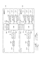
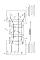
図1に示す車載ネットワーク装置は、2つの通信用ECU10、20と、これらの間を接続するエリア間接続部17とで構成されている。一方の通信用ECU10は、車両上の「エリア1」に配置され、他方の通信用ECU20は、「エリア2」に配置される。
The in-vehicle network device shown in FIG. 1 is composed of two
通信用ECU10は、互いに独立している複数系統の通信線11−1、11−2、11−3、11−4、および通信用ECU20の間の通信を可能にするための機能を備えている。通信線11−1、11−2、および11−3のそれぞれは、通信機能を有する様々な車載機器(ECU等)の接続を許容するバスの機能を有している。したがって、通信線11−1、11−2、および11−3のそれぞれに接続する車載機器の数は必要に応じて変更できる。複数系統の通信線11−1、11−2、および11−3は、例えば通信速度などの設計仕様や通信プロトコルなどが互いに異なる場合がある。
The
また、通信線11−4は、車両外部の機器と、車載機器との間で通信するための機能を有している。したがって、通信線11−4を利用して通信する場合には、通信の安全性を確保するための機能を備えるようにする。通信線11−1、11−2、および11−3、11−4のそれぞれは、例えばCAN (Controller Area Network)規格に対応した設計仕様の場合には、それぞれ2本の電線で構成される。 Further, the communication lines 11-4 have a function for communicating between a device outside the vehicle and an in-vehicle device. Therefore, when communicating using the communication lines 11-4, a function for ensuring the safety of communication is provided. Each of the communication lines 11-1, 11-2, and 11-3, 11-4 is composed of two electric wires, for example, in the case of a design specification corresponding to the CAN (Controller Area Network) standard.
図1に示した通信用ECU10は、通信中継器12、ルータ13、ドライバIC(集積回路)14−1〜14−4、およびセキュリティ管理部15を備えている。通信中継器12とルータ13との間はルータ接続部16を介して接続されている。通信中継器12の各入出力ポート12a、12b、12c、および12dと通信線11−1、11−2、11−3、および11−4との間は、それぞれドライバIC14−1、14−2、14−3、および14−4を介して接続されている。また、入出力ポート12dとドライバIC14−4との間にセキュリティ管理部15を接続してある。
The
通信中継器12は、系統の種類や通信仕様が共通のエリア内および複数エリア間の通信を単純に中継する機能のみを有している。つまり、図1に示した通信用ECU10の例では、4系統の通信線11−1〜11−4が存在するので、通信中継器12は4系統の通信をそれぞれ独立した状態で中継する。また、4系統の通信線11−1〜11−4の通信をそれぞれ独立した状態で中継できるように、通信中継器12と通信用ECU20との間を接続するエリア間接続部17は、それぞれ通信線11−1〜11−4と対応する4系統の通信線を含んでいる。
The
一方、車載ネットワークの場合には、系統の種類や通信仕様が異なる複数系統を跨ぐ状態で通信を中継する機能も必要になる。例えば、通信線11−1に接続される車載機器と、通信線11−3に接続される他の車載機器との間で通信が必要になる場合がある。このような複数の系統間を跨ぐ通信を可能にするために、通信中継器12の他に、ルータ13が備わっている。
On the other hand, in the case of an in-vehicle network, a function of relaying communication across a plurality of systems having different system types and communication specifications is also required. For example, communication may be required between an in-vehicle device connected to the communication line 11-1 and another in-vehicle device connected to the communication line 11-3. In addition to the
つまり、ルータ13は、例えば通信線11−1、11−2、11−3、および11−4のそれぞれから送信された信号の送信先を必要に応じて系統が異なる他の通信線11−1〜11−4に切り替えるための経路制御機能を備えている。また、ルータ13は、例えば通信プロトコルの違いやその他の規格の違いを吸収して異なる系統間の通信に対応するゲートウェイ(GW)の機能も備えている。
That is, the
ドライバIC14−1〜14−4は、それぞれ、通信線11−1〜11−4の各系統の通信規格に合わせた信号処理を行う。すなわち、通信規格に応じて入出力する信号の増幅や波形整形などの処理を行う受信部および送信部を内蔵している。 Each of the driver ICs 14-1 to 14-4 performs signal processing according to the communication standard of each system of the communication lines 11-1 to 11-4. That is, it has a built-in receiver and transmitter that perform processing such as amplification and waveform shaping of input / output signals according to the communication standard.
通信中継器12とルータ13との間を接続するルータ接続部16は、通信線11−1〜11−4の系統数と同数の4系統の独立した通信線を備えている。したがって、ルータ接続部16は、通信線11−1〜11−4の信号をそれぞれ入力したり、通信線11−1〜11−4に対してそれぞれ信号を出力することができる。これらの信号は、通信中継器12により中継される。
The
一方、エリア2に配置される通信用ECU20に、4系統の通信線21−1、21−2、21−3、および21−4が接続されている。これらの通信線21−1、21−2、21−3、および21−4は、それぞれエリア1に配置される通信線11−1、11−2、11−3、および11−4と対応している。
On the other hand, four communication lines 21-1, 21-2, 21-3, and 21-4 are connected to the
つまり、通信線21−1と通信線11−1は通信プロトコルや通信規格が同一の仕様になっている。また、通信線21−2と通信線11−2の仕様が同一であり、通信線21−3と通信線11−3の仕様が同一であり、通信線21−4と通信線11−4の仕様も同一である。したがって、同じ種類の車載機器を、例えば同じ系統の通信線11−1、21−1のいずれにも接続することができる。実際には通信用ECU10、20が異なるエリアに配置されるので、各車載機器は例えば対応する同じ系統の通信線11−1、21−1のうち近い方、あるいは都合のよい方に接続される。また、同じ系統の通信線11−4と同様に、通信線21−4は車外の機器と接続するために利用される。
That is, the communication line 21-1 and the communication line 11-1 have the same specifications in terms of communication protocol and communication standard. Further, the specifications of the communication line 21-2 and the communication line 11-2 are the same, the specifications of the communication line 21-3 and the communication line 11-3 are the same, and the specifications of the communication line 21-4 and the communication line 11-4 are the same. The specifications are also the same. Therefore, the same type of in-vehicle device can be connected to, for example, any of the communication lines 11-1 and 21-1 of the same system. Since the
図1に示した通信用ECU20は、通信中継器22、4系統のドライバIC24−1〜24−4、およびセキュリティ管理部25を備えている。つまり、ルータ13が存在しない点を除き、通信用ECU20の構成は通信用ECU10と同様である。
The
通信中継器22は、エリア2の通信線21−1〜21−4と、エリア1の通信線11−1〜11−4の通信を同じ系統毎に中継するための機能を有している。通信中継器22の入出力ポート22a、22b、22c、および22dは、それぞれ通信線21−1、21−2、21−3、および21−4の信号を入出力するようになっている。入出力ポート22a、22b、および22cは、それぞれドライバIC24−1〜24−3を介して通信線21−1、21−2、21−3、および21−4と接続されている。また、入出力ポート22dは、セキュリティ管理部25およびドライバIC24−4を介して通信線21−4と接続されている。
The
<中継動作の概要>
<通信中継器12の機能>
エリア1の通信中継器12は、通信線11−1から入出力ポート12aに信号が入力されると、この信号と同じ情報を、エリア間接続部17の同じ系統の通信線17aにそのまま送信する。また、入出力ポート12aに入力された信号と同じ情報が、通信中継器12を通り、ルータ接続部16の同じ系統の通信線16aにもそのまま送出される。
<Overview of relay operation>
<Function of
When a signal is input from the communication line 11-1 to the input /
同様に、通信中継器12は、通信線11−2から入出力ポート12bに信号が入力されると、この信号と同じ情報を、エリア間接続部17の同じ系統の通信線17bにそのまま送信する。また、入出力ポート12bに入力された信号と同じ情報が、通信中継器12を通り、ルータ接続部16の同じ系統の通信線16bにもそのまま送出される。
Similarly, when a signal is input from the communication line 11-2 to the input /
また、通信中継器12は、通信線11−3から入出力ポート12cに信号が入力されると、この信号と同じ情報を、エリア間接続部17の同じ系統の通信線17cにそのまま送信するとともに、ルータ接続部16の同じ系統の通信線16cにもそのまま送出する。同様に、通信中継器12は通信線11−4から入出力ポート12dに信号が入力されると、この信号と同じ情報を、エリア間接続部17の同じ系統の通信線17dにそのまま送信するとともに、ルータ接続部16の同じ系統の通信線16dにもそのまま送出する。
Further, when a signal is input from the communication line 11-3 to the input /
また、通信中継器12は、エリア間接続部17の1番目の系統の通信線17aから信号が入力されると、この信号と同じ情報を、同じ系統の入出力ポート12aから通信線11−1に送信する。また、通信線17aから入力された信号と同じ情報が、通信中継器12を経由して同じ系統の通信線16aにも出力される。
Further, when a signal is input from the
同様に、通信中継器12は、エリア間接続部17の2番目の系統の通信線17bから信号が入力されると、この信号と同じ情報を、同じ系統の入出力ポート12bから通信線11−2に送信するとともに、同じ系統の通信線16bにも出力する。
Similarly, when a signal is input from the
また、通信中継器12は、エリア間接続部17の3番目の系統の通信線17cから信号が入力されると、この信号と同じ情報を、同じ系統の入出力ポート12cから通信線11−3に送信するとともに、同じ系統の通信線16cにも出力する。同様に、通信中継器12はエリア間接続部17の4番目の系統の通信線17dから信号が入力されると、この信号と同じ情報を、同じ系統の入出力ポート12dから通信線11−1に送信するとともに、同じ系統の通信線16dにも出力する。
Further, when a signal is input from the
<通信中継器22の機能>
一方、エリア2の通信中継器22は、通信線21−1から入出力ポート22aに信号が入力されると、この信号と同じ情報を、エリア間接続部17の同じ系統の通信線17aにそのまま送信する。同様に、通信中継器22は、通信線21−2から入出力ポート22bに信号が入力されると、この信号と同じ情報を、エリア間接続部17の同じ系統の通信線17bにそのまま送信する。
<Function of
On the other hand, when a signal is input from the communication line 21-1 to the input /
また、通信中継器22は、通信線21−3から入出力ポート22cに信号が入力されると、この信号と同じ情報を、エリア間接続部17の同じ系統の通信線17cにそのまま送信する。また、通信中継器22は、通信線21−4から入出力ポート22dに信号が入力されると、この信号と同じ情報を、エリア間接続部17の同じ系統の通信線17dにそのまま送信する。
When a signal is input from the communication line 21-3 to the input /
また、通信中継器22は、エリア間接続部17の1番目の系統の通信線17aから信号が入力されると、この信号と同じ情報を、同じ系統の入出力ポート22aから通信線21−1に送信する。また、通信中継器22は、エリア間接続部17の2番目の系統の通信線17bから信号が入力されると、この信号と同じ情報を、同じ系統の入出力ポート22bから通信線21−2に送信する。
Further, when a signal is input from the
同様に、通信中継器22は、エリア間接続部17の3番目の系統の通信線17cから信号が入力されると、この信号と同じ情報を、同じ系統の入出力ポート22cから通信線21−3に送信する。また、通信中継器22は、エリア間接続部17の4番目の系統の通信線17dから信号が入力されると、この信号と同じ情報を、同じ系統の入出力ポート22dから通信線21−4に送信する。
Similarly, when a signal is input from the
<全体の中継動作>
したがって、仮にルータ13の機能を使用しない場合には、通信中継器12および22は、同じ系統に属する複数エリアの通信線の間でのみ各信号を中継し通信するようになっている。
<Overall relay operation>
Therefore, if the function of the
例えば、通信線11−1からドライバIC14−1を経由して通信中継器12の入出力ポート12aに信号が入力されると、この信号が、通信中継器12、通信線17a、通信中継器22、ドライバIC24−1を経由して、通信線21−1に送信される。同様に、通信線11−2からドライバIC14−2を経由して通信中継器12の入出力ポート12bに入力された信号は、通信中継器12、通信線17b、通信中継器22、ドライバIC24−2を経由して、通信線21−2に送信される。
For example, when a signal is input from the communication line 11-1 to the input /
また、通信線11−3からドライバIC14−3を経由して通信中継器12の入出力ポート12cに入力された信号は、通信中継器12、通信線17c、通信中継器22、ドライバIC24−3を経由して、通信線21−3に送信される。同様に、通信線11−4からドライバIC14−4を経由して通信中継器12の入出力ポート12dに入力された信号は、通信中継器12、通信線17d、通信中継器22、ドライバIC24−4を経由して、通信線21−4に送信される。
Further, the signals input from the communication line 11-3 to the input /
また、通信線21−1からドライバIC24−1を経由して通信中継器22の入出力ポート22aに信号が入力されると、この信号が、通信中継器22、通信線17a、通信中継器12、ドライバIC14−1を経由して、通信線11−1に送信される。同様に、通信線21−2から入出力ポート22bに入力された信号は、通信中継器22、通信線17b、通信中継器12、ドライバIC14−2を経由して、通信線11−2に送信される。
Further, when a signal is input from the communication line 21-1 to the input /
また、通信線21−3からドライバIC24−3を経由して通信中継器22の入出力ポート22cに信号が入力されると、この信号が、通信中継器22、通信線17c、通信中継器12、ドライバIC14−3を経由して、通信線11−3に送信される。同様に、通信線21−4から入出力ポート22dに入力された信号は、通信中継器22、通信線17d、通信中継器12、ドライバIC14−4を経由して、通信線11−4に送信される。
Further, when a signal is input from the communication line 21-3 to the input /
上記のような動作により、通常は同じ系統に属している各通信線に接続されている機器(複数のECU等)の間で通信を行う際に、通信中継器12、22は、信号に含まれる宛先に関する情報を取り出す必要がないので、信号の中継において遅延が発生することを抑制できる。なお、種類の異なる系統を跨ぐ通信が必要になる場合には、ルータ13の機能により、必要に応じて系統の異なる複数の通信線の間で通信経路を接続する。
By the above operation, the
ルータ13は、例えばルータ接続部16の1番目の通信線16aに入力された信号と同じ情報を、2番目〜4番目の通信線16b〜16dに送出することができる。したがって、例えばエリア1の通信線11−1から送信された信号を、系統が異なる通信線11−2〜11−4、および21−2〜21−4に選択的に送信することができる。
For example, the
但し、系統が異なる通信線は、通信プロトコルや通信規格が異なる場合があるので、複数系統を跨ぐ状態で通信する場合には、通信プロトコルや通信規格の違いを吸収する機能が必要になるため、ルータ13は、この機能を備えるようになっている。したがって、ルータ13を備えた通信用ECU10は、系統が違う複数の通信線を跨いで通信する場合のゲートウェイとしての機能を含んでいる。図1のような構成の場合には、単一のルータ13が同じ車両上のネットワーク全体の制御を実施できるので、ルータ13はゲートウェイを含む1箇所の通信用ECU10のみに搭載すればよい。
However, communication lines with different systems may have different communication protocols and communication standards. Therefore, when communicating across multiple systems, a function to absorb the differences in communication protocols and communication standards is required. The
<通信線の系統毎の特性>
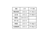
複数グループに区分される車両上の通信線の系統毎の特性の傾向を図2に示す。図2に示した例では、車両に搭載される様々な車載機器(ECUなどの電装品)を機能毎の区分として運転支援系、走行系、電源系、ボデー系、情報系、外部接続用の6系統に区分する場合を想定している。
<Characteristics of each communication line system>
FIG. 2 shows the tendency of the characteristics of each communication line system on the vehicle divided into a plurality of groups. In the example shown in FIG. 2, various in-vehicle devices (electrical components such as ECUs) mounted on the vehicle are classified by function for driving support system, traveling system, power supply system, body system, information system, and external connection. It is assumed that the system is divided into 6 systems.
また、図2に示した「リスク」は、該当する機器の誤作動などに起因する影響の度合を表す。また、「リスク高」は事故に繋がる可能性が高い場合、「リスク中」は事故に繋がる可能性がやや高い場合、「リスク小」はユーザが不便を感じる場合にそれぞれ相当する。 Further, the “risk” shown in FIG. 2 indicates the degree of influence caused by a malfunction of the corresponding device. In addition, "high risk" corresponds to a case where there is a high possibility of leading to an accident, "medium risk" corresponds to a case where there is a slightly high possibility of leading to an accident, and "low risk" corresponds to a case where the user feels inconvenience.
また、図2の例では通信線を6系統に区分する場合を想定しているが、特性の傾向の類似性を考慮すれば、複数の系統を同じグループに統合して全体の系統数を減らすこともできる。例えば、図2の内容において運転支援系、走行系の2系統は、リスクおよび通信データ量の特性が類似しているので同じグループに区分してもよい。同様に、電源系、ボデー系の2系統も類似しているので同じグループに区分してもよい。更に、情報系、外部接続用の2系統も同じグループに区分してもよい。 Further, in the example of FIG. 2, it is assumed that the communication line is divided into 6 systems, but considering the similarity of the tendency of the characteristics, a plurality of systems are integrated into the same group to reduce the total number of systems. You can also do it. For example, in the content of FIG. 2, the two systems, the driving support system and the driving system, may be classified into the same group because the characteristics of the risk and the amount of communication data are similar. Similarly, since the power supply system and the body system are similar, they may be classified into the same group. Further, the information system and the two systems for external connection may be classified into the same group.
このように、様々な観点から類似性を考慮して各系統の通信線に接続する車載機器の割り当てを決定することにより、ネットワークを構成する各系統の通信線11−1〜11−4、21−1〜21−4の通信仕様を系統毎に最適化することが可能である。 In this way, by deciding the allocation of the in-vehicle devices connected to the communication lines of each system in consideration of the similarity from various viewpoints, the communication lines 11-1 to 11-4, 21 of each system constituting the network are determined. It is possible to optimize the communication specifications of -1 to 21-4 for each system.
また、例えば図1に示した車載ネットワーク装置は、4系統の通信線11−1〜11−4、および21−1〜21−4を備えているので、図2に示した6系統の通信線を部分的に統合して4種類のグループに区分することが想定される。例えば、運転支援系、および走行系の車載機器を1番目の系統の通信線11−1又は21−1に接続する。また、電源系、およびボデー系の車載機器を2番目の系統の通信線11−2又は21−2に接続する。また、情報系の車載機器は3番目の系統の通信線11−3又は21−3に接続する。また、外部接続用の車載機器はセキュリティ管理を必要とするので、4番目の系統の通信線11−4又は21−4に接続する。 Further, for example, since the in-vehicle network device shown in FIG. 1 includes four communication lines 11-1 to 11-4 and 21-1 to 21-4, the six communication lines shown in FIG. 2 are provided. Is expected to be partially integrated and divided into four types of groups. For example, the in-vehicle device of the driving support system and the traveling system is connected to the communication line 11-1 or 21-1 of the first system. Further, the power supply system and the body system in-vehicle device are connected to the communication line 11-2 or 21-2 of the second system. Further, the in-vehicle device of the information system is connected to the communication line 11-3 or 21-3 of the third system. Further, since the in-vehicle device for external connection requires security management, it is connected to the communication line 11-4 or 21-4 of the fourth system.
<ルータ13の機能>
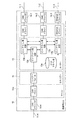
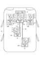
通信中継器12を除いた通信用ECU10の構成を図3に示す。なお、図3の例では、通信線11−1、11−2、および11−4がCANの通信規格に合わせて設計され、通信線11−3がイーサネット(登録商標)の通信規格に合わせて設計される場合を想定している。
<Function of
FIG. 3 shows the configuration of the
図3に示した通信用ECU10は、マイクロコンピュータ(マイコン)10aと、CAN用のドライバIC14−1、14−2、14−4と、イーサネット用のドライバIC14−3とを備えている。また、マイクロコンピュータ10aの内部には、セキュリティ管理部15の機能、ルータ13の機能、および系統毎のドライバの機能が含まれている。
The
セキュリティ管理部15は、ファイアウォールの機能や、暗号化通信のための機能を備えている。ルータ13は、ビットアサイン表保持部13a、およびビットアサイン表比較部13bの機能を有している。ビットアサイン表は、通信線11−1〜11−4等の各系統が対応している複数種類の通信規格のそれぞれに応じた通信プロトコルを処理するために必要な通信ビット毎の情報の割り当てを示している。
The
ルータ13は、系統を跨いで通信するように通信経路を接続することができる。例えば、通信線11−1に接続される車載機器が送信した信号を、別系統の通信線11−3に送信することができる。但し、図3の例では通信線11−1の通信規格がCANであり、通信線11−3の通信規格がイーサネットであるので、通信規格の違いをルータ13で吸収する必要がある。
The
したがって、ルータ13は、ビットアサイン表保持部13a上のビットアサイン表を参照し、ビットアサイン表比較部13bの処理により、送信元と送信先の各々の通信規格における各ビットの割り当てを認識すると共に、通信プロトコルの違いを吸収したり、必要に応じてデータ変換の処理を実施する。
Therefore, the
<車載ネットワーク装置の利点>
図1に示した車載ネットワーク装置においては、エリア毎に配置される各通信用ECU10、20の内部に設けた通信中継器12、22をエリア間接続部17で接続し、複数エリア間での通信を可能にしている。また、ここで各通信中継器12、22については単純な中継機能以外の動作を必要としないので、安価なハードウェアの部品を利用するだけで高速の通信を実現できる。したがって、複数エリア間を接続する経路の通信において伝送遅延時間を短縮できる。また、複数のエリアに通信用ECU10、20をそれぞれ配置する場合でも、複数系統の通信線11−1〜11−4、21−1〜21−4を跨ぐ通信を行うために必要なルータ13は、1台だけしか必要としないので、ネットワーク全体の部品コストを大幅に低減できる。
<Advantages of in-vehicle network equipment>
In the in-vehicle network device shown in FIG. 1,
<変形例の説明>
<車載ネットワーク装置の構成>
車載ネットワーク装置の構成例−2を図4に示す。図4に示した車載ネットワーク装置は、図1に示した構成の変形例であり、通信中継器12と通信中継器22との間を接続する箇所に光接続用幹線18を採用している点の構成のみが異なっている。
<Explanation of modified example>
<Configuration of in-vehicle network device>
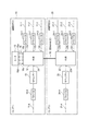
FIG. 4 shows a configuration example-2 of the in-vehicle network device. The in-vehicle network device shown in FIG. 4 is a modification of the configuration shown in FIG. 1, and employs an optical
車両上で複数エリアの間を接続する通信線、つまり図1に示したエリア間接続部17や図4に示した光接続用幹線18については、大量のデータをやり取りすることが想定される。しかも、車両側の仕様として許容できる通信の遅延時間が非常に短く定められる可能性が高い。
It is assumed that a large amount of data is exchanged with respect to the communication line connecting a plurality of areas on the vehicle, that is, the
したがって、複数のエリア間を接続する通信用ECU10、20の間の通信を高速化する必要があり、各通信用ECU10、20内部の処理も高速化する必要がある。図4に示した構成のように、通信用ECU10、20の間を光接続用幹線18で接続することにより、高速の通信が可能になり、大量のデータ伝送も可能になる。すなわち、光信号を用いてデータ通信を行うので、通信の周波数を上げてビットレートを上げることができる。光接続用幹線18の通信については、例えばイーサネットの規格に従って光通信を行うことが想定される。
Therefore, it is necessary to speed up the communication between the
<伝送路の構成例>
図5は、図4に示した車載ネットワーク装置における伝送路の構成例である。図5に示した例では、光接続用幹線18の光ファイバの箇所に、互いに独立した4つの光伝送路18a、18b、18c、および18dを形成している。実際には、4つの光伝送路18a〜18dの信号を時分割した4つの通信チャネルのタイミングで順次に送信することで、これらの光伝送路18a〜18dを形成できる。勿論、他の方法を利用することも可能である。例えば、互いに波長が異なる複数の光信号を同じ光ファイバに通すことにより、同時に複数の通信チャネルを確保できる。
<Example of transmission line configuration>
FIG. 5 is a configuration example of a transmission line in the in-vehicle network device shown in FIG. In the example shown in FIG. 5, four independent
図4に示したように、光接続用幹線18内に独立した4つの光伝送路18a〜18dを形成することにより、各通信中継器12、22の構造が複雑化するのを避けることができる。すなわち、4系統の通信線11−1〜11−4の情報を、そのまま対応する系統の光伝送路18a〜18dに通して、4系統の通信線21−1〜21−4にそれぞれ送出することができる。つまり、通信中継器12で複数系統の信号を合成したり、通信中継器22が受信した信号から系統毎に信号を分離するような特別な処理を行う必要がない。
As shown in FIG. 4, by forming four independent
<車両上の車載ネットワーク装置の配置例>
車両30上に配置した車載ネットワーク装置の構成例を図6に示す。図6に示した車載ネットワーク装置は、ゲートウェイ(GW)の機能を有する1つの通信用ECU10Aと、ゲートウェイの機能を含まない4つの通信用ECU20A、20B、20C、20Dとを含んでいる。なお、このネットワークに接続する通信用ECU20A〜20Dの総数は必要に応じて増減される。
<Example of placement of in-vehicle network device on vehicle>
FIG. 6 shows a configuration example of the in-vehicle network device arranged on the
5つの通信用ECU10A、20A、20B、20C、20Dは、車両30上の互いに異なるエリアに配置されている。代表例としては、エンジンコンパートメント、左ドア近傍、インストルメントパネル、右ドア近傍、ラゲッジルームの各エリアに、通信用ECU10A、20A、20B、20C、および20Dを配置することが想定される。勿論、他のエリア、例えば車体ルーフの近傍、シートの近傍、バンパーの近傍などの各エリアに配置してもよい。
The five
図6に示した例では、通信用ECU10Aの通信中継器12と、通信用ECU20Aの通信中継器22との間がエリア間接続部17Aを介して接続されている。また、通信用ECU10Aの通信中継器12と、通信用ECU20Bの通信中継器22との間がエリア間接続部17Bを介して接続されている。また、通信用ECU10Aの通信中継器12と、通信用ECU20Cの通信中継器22との間がエリア間接続部17Cを介して接続されている。更に、通信用ECU10Aの通信中継器12と、通信用ECU20Dの通信中継器22との間がエリア間接続部17Dを介して接続されている。
In the example shown in FIG. 6, the
各エリア間接続部17A、17B、17C、および17Dのそれぞれは、エリア間接続部17と同様に4系統の独立した通信線を含んでいる。図6の例では、通信中継器12、22の各々は、イーサネットの規格に合わせて設計してある。
Each of the
通信用ECU10Aの構成は、通信中継器12に複数のエリア間接続部17A、17B、17C、17Dを接続できるように変更した以外は図1に示した通信用ECU10の構成と同様である。また、通信用ECU20A〜20Eの構成は、図1に示した通信用ECU20と同様である。
The configuration of the
この車両30の各部に配置される各種車載機器(ECUなどの電装品:図示せず)は、通信用ECU10A、20A〜20Dの複数系統の通信線11−1〜11−4、21−1〜21−4のいずれかに接続することにより、このネットワークを利用して他の機器と通信できる。
Various in-vehicle devices (electrical components such as ECUs: not shown) arranged in each part of the
各系統の通信線11−1〜11−4、21−1〜21−4のいずれかに接続された各種車載機器は、同じ通信線に送出された全ての信号を受信することができる。そして、例えばCANの通信規格の場合には、各車載機器はデータフレームに含まれるIDを識別することにより、自分宛のデータフレームとそれ以外とを区別して、自分宛のデータフレームだけを受信しそれ以外は廃棄する。また、イーサネットの通信規格の場合には、各車載機器はMACフレームに含まれる宛先MACアドレスが自分と一致するか否かを識別し、自分宛のMACフレームのみを受信し、それ以外のMACフレームは廃棄する。したがって、バス構造の各々の通信線に複数の車載機器を接続することができる。 Various in-vehicle devices connected to any of the communication lines 11-1 to 11-4 and 21-1 to 21-4 of each system can receive all the signals transmitted to the same communication line. Then, for example, in the case of the CAN communication standard, each in-vehicle device distinguishes the data frame addressed to itself from the other by identifying the ID included in the data frame, and receives only the data frame addressed to itself. Discard everything else. In the case of the Ethernet communication standard, each in-vehicle device identifies whether or not the destination MAC address included in the MAC frame matches itself, receives only the MAC frame addressed to itself, and receives other MAC frames. Discard. Therefore, a plurality of in-vehicle devices can be connected to each communication line of the bus structure.
ここで、上述した本発明の実施形態に係る車載ネットワーク装置の特徴をそれぞれ以下[1]〜[5]に簡潔に纏めて列記する。
[1] 車両上に配置され、
少なくとも2組の複数の通信線(11−1〜11−4)に接続された通信中継器(12)と、
前記通信中継器を通る信号の通信経路を制御するルータ(13)と、
を備え、
前記複数の通信線は、予め定めた系統毎に独立し、
前記通信中継器は、前記2組のうち一方の組の通信線から信号を受信すると、当該通信線の系統と同一系統の他方の組の通信線と、前記ルータと、に信号を送信し、
前記ルータは、前記他方の組の通信線のうち前記一方の組の通信線の系統と異なる系統の通信線に信号を送信する、
ことを特徴とする車載ネットワーク装置。
Here, the features of the in-vehicle network device according to the above-described embodiment of the present invention are briefly summarized and listed below [1] to [5], respectively.
[1] Placed on the vehicle
A communication repeater (12) connected to at least two sets of communication lines (11-1 to 11-4), and
A router (13) that controls the communication path of the signal passing through the communication repeater, and
With
The plurality of communication lines are independent for each predetermined system.
When the communication repeater receives a signal from one of the two sets of communication lines, the communication repeater transmits a signal to the other set of communication lines of the same system as the communication line system and the router.
The router transmits a signal to a communication line of a system different from the system of the communication line of the other set of communication lines.
An in-vehicle network device characterized by this.
[3] 前記複数の通信中継器(12、22)それぞれは、前記車両中において、互いに異なる機能を提供する部位がそれぞれ配置される互いに独立した空間に設置される(図6参照)、 [3] Each of the plurality of communication repeaters (12, 22) is installed in a space independent of each other in which parts providing different functions are arranged in the vehicle (see FIG. 6).
[4] 前記エリア間接続部の前記通信線は、前記機器接続部の前記通信線よりも高速通信が可能な幹線(光接続用幹線18)を有し、
少なくとも前記機器接続部の通信線数と同数の前記通信回線(光伝送路18a〜18d)が前記幹線に含まれる、
ことを特徴とする上記[2]又は[3]に記載の車載ネットワーク装置。
[4] The communication line of the inter-area connection portion has a trunk line (optical connection trunk line 18) capable of higher speed communication than the communication line of the device connection portion.
The trunk line includes at least the same number of communication lines (
The vehicle-mounted network device according to the above [2] or [3].
[5] 前記複数の通信中継器の少なくとも1つと、前記機器接続部の1系統の前記通信線との間に、通信のセキュリティを管理する機器(セキュリティ管理部15、25)が接続された、
ことを特徴とする上記[2]乃至[4]のいずれかに記載の車載ネットワーク装置。
[5] A device (
The vehicle-mounted network device according to any one of the above [2] to [4].
10,10A,20,20A,20B,20C,20D 通信用ECU
10a マイクロコンピュータ
11−1,11−2,11−3,11−4 通信線
12,22 通信中継器
12a,12b,12c,12d 入出力ポート
13 ルータ
13a ビットアサイン表保持部
13b ビットアサイン表比較部
14−1,14−2,14−3,14−4 ドライバIC
15,25 セキュリティ管理部
16 ルータ接続部
17,17A,17B,17C,17D エリア間接続部
18 光接続用幹線
18a,18b,18c,18d 光伝送路
21−1,21−2,21−3,21−4 通信線
22a,22b,22c,22d 入出力ポート
24−1,24−2,24−3,24−4 ドライバIC
30 車両
10,10A, 20,20A, 20B, 20C, 20D communication ECU
10a Microcomputer 11-1, 11-2, 11-3, 11-4
15, 25
30 vehicles
Claims (5)
前記通信中継器に接続される複数の接続部であって、それぞれが2以上の所定数の系統の互いに独立した通信線を有する複数の接続部と、
前記通信中継器を通る信号の通信経路を制御するルータと、
前記通信中継器と前記ルータとの間を前記所定数の系統の互いに独立した通信線で相互に接続するルータ接続部と、
を備え、
前記通信中継器は、一の前記接続部が有する一の系統の前記通信線から信号を受信すると、前記一の前記接続部以外の残りの前記接続部が有する前記一の系統と同じ系統の前記通信線と、前記ルータ接続部が有する前記一の系統と同じ系統の前記通信線と、に前記信号と同じ情報を送信し、前記ルータ接続部が有する一の系統の前記通信線から信号を受信すると、前記複数の接続部それぞれが有する前記一の系統と同じ系統の前記通信線に前記信号と同じ情報を送信し、
前記ルータは、前記ルータ接続部が有する一の系統の前記通信線から信号を受信すると、前記ルータ接続部が有する前記一の系統とは異なる何れか1つの系統の前記通信線に選択的に、前記信号と同じ情報を送信する、
ことを特徴とする車載ネットワーク装置。 Communication repeaters that can be placed on the vehicle and
A plurality of connection portions connected to the communication repeater, each of which has two or more predetermined number of systems having independent communication lines, and a plurality of connection portions.
A router that controls the communication path of the signal passing through the communication repeater, and
A router connection unit that connects the communication repeater and the router to each other by communication lines independent of each other of the predetermined number of systems, and
With
When the communication repeater receives a signal from the communication line of one system of the one connection unit, the communication repeater has the same system as the one system of the remaining connection parts other than the one connection unit. The same information as the signal is transmitted to the communication line and the communication line of the same system as the one system of the router connection unit, and a signal is received from the communication line of the one system of the router connection unit. Then, the same information as the signal is transmitted to the communication line of the same system as the one system of each of the plurality of connection units.
When the router receives a signal from the communication line of one system of the router connection unit, the router selectively selects the communication line of any one system different from the communication line of the router connection unit . Sends the same information as the signal,
An in-vehicle network device characterized by this.
各前記通信中継器に接続される機器接続部であって、2以上の所定数の系統の互いに独立した通信線を有する機器接続部と、
前記複数の通信中継器それぞれを通る信号の通信経路を制御するルータと、
一の前記通信中継器と前記ルータとの間を前記所定数の系統の互いに独立した通信線で相互に接続するルータ接続部と、
前記一の前記通信中継器と前記一の前記通信中継器とは異なる各前記通信中継器との間を前記所定数の系統の互いに独立した通信線で相互に接続するエリア間接続部と、
を備え、
前記一の前記通信中継器は、前記機器接続部が有する一の系統の前記通信線から信号を受信すると、前記エリア間接続部が有する前記一の系統と同じ系統の前記通信線と、前記ルータ接続部が有する前記一の系統と同じ系統の前記通信線と、に前記信号と同じ情報を送信し、前記ルータ接続部が有する一の系統の前記通信線から信号を受信すると、前記機器接続部が有する前記一の系統と同じ系統の前記通信線と、前記エリア間接続部が有する前記一の系統と同じ系統の前記通信線と、に前記信号と同じ情報を送信し、前記エリア間接続部が有する一の系統の前記通信線から信号を受信すると、前記機器接続部が有する前記一の系統と同じ系統の前記通信線と、前記ルータ接続部が有する前記一の系統と同じ系統の前記通信線と、に前記信号と同じ情報を送信し、
前記一の前記通信中継器とは異なる各前記通信中継器は、前記機器接続部が有する一の系統の前記通信線から信号を受信すると、前記エリア間接続部が有する前記一の系統と同じ系統の前記通信線に前記信号と同じ情報を送信し、前記エリア間接続部が有する一の系統の前記通信線から信号を受信すると、前記機器接続部が有する前記一の系統と同じ系統の前記通信線に前記信号と同じ情報を送信し、
前記ルータは、前記ルータ接続部が有する一の系統の前記通信線から信号を受信すると、前記ルータ接続部が有する前記一の系統とは異なる何れか1つの系統の前記通信線に選択的に、前記信号と同じ情報を送信する、
ことを特徴とする車載ネットワーク装置。 Multiple communication repeaters that can be placed in different areas on the vehicle,
A device connection unit connected to each of the communication repeaters, which has two or more predetermined number of systems having independent communication lines, and a device connection unit.
A router that controls the communication path of signals passing through each of the plurality of communication repeaters, and
A router connection unit that connects the communication repeater and the router to each other by communication lines independent of each other of the predetermined number of systems.
An inter-area connection unit that connects the one communication repeater and each communication repeater different from the one communication repeater to each other by communication lines independent of each other of the predetermined number of systems, and
With
When the one communication repeater receives a signal from the communication line of one system of the device connection unit, the communication line of the same system as the one system of the inter-area connection unit and the router. When the same information as the signal is transmitted to the communication line of the same system as the one system of the connection unit and the signal is received from the communication line of the one system of the router connection unit, the device connection unit The same information as the signal is transmitted to the communication line of the same system as the one system and the communication line of the same system as the one system of the inter-area connection unit. When a signal is received from the communication line of one system of the router, the communication line of the same system as the one system of the device connection unit and the communication of the same system as the one system of the router connection unit have. Send the same information to the line and the signal,
When each communication repeater different from the one communication repeater receives a signal from the communication line of one system of the device connection unit, it has the same system as the one system of the inter-area connection unit. When the same information as the signal is transmitted to the communication line and a signal is received from the communication line of one system of the inter-area connection unit, the communication of the same system as the one system of the device connection unit is received. Send the same information to the line as the signal
When the router receives a signal from the communication line of one system of the router connection unit, the router selectively selects the communication line of any one system different from the communication line of the router connection unit . Sends the same information as the signal,
An in-vehicle network device characterized by this.
ことを特徴とする請求項2に記載の車載ネットワーク装置。 Each of the plurality of communication repeaters is installed in different spaces in the vehicle in which parts providing different functions are arranged.
The vehicle-mounted network device according to claim 2.
前記幹線に、前記所定数の系統の互いに独立した前記通信線に代えて、前記所定数の系統の互いに独立した伝送路が含まれる、
ことを特徴とする請求項2又は請求項3に記載の車載ネットワーク装置。 The communication line of the inter-area connection portion has a trunk line capable of higher speed communication than the communication line of the device connection portion.
The trunk line includes transmission lines independent of each other of the predetermined number of systems in place of the communication lines independent of each other of the predetermined number of systems.
The vehicle-mounted network device according to claim 2 or 3, wherein the vehicle-mounted network device is characterized by the above.
ことを特徴とする請求項2乃至請求項4のいずれか1項に記載の車載ネットワーク装置。 A device that manages communication security is connected between at least one of the plurality of communication repeaters and the communication line of one system of the device connection unit.
The vehicle-mounted network device according to any one of claims 2 to 4, characterized in that.
Priority Applications (4)
| Application Number | Priority Date | Filing Date | Title |
|---|---|---|---|
| JP2017177604A JP6768614B2 (en) | 2017-09-15 | 2017-09-15 | In-vehicle network device |
| US16/121,061 US11057239B2 (en) | 2017-09-15 | 2018-09-04 | Vehicular network device |
| DE102018215706.5A DE102018215706B4 (en) | 2017-09-15 | 2018-09-14 | vehicle network device |
| CN201811080818.3A CN109660434B (en) | 2017-09-15 | 2018-09-17 | Vehicle network device |
Applications Claiming Priority (1)
| Application Number | Priority Date | Filing Date | Title |
|---|---|---|---|
| JP2017177604A JP6768614B2 (en) | 2017-09-15 | 2017-09-15 | In-vehicle network device |
Publications (2)
| Publication Number | Publication Date |
|---|---|
| JP2019054427A JP2019054427A (en) | 2019-04-04 |
| JP6768614B2 true JP6768614B2 (en) | 2020-10-14 |
Family
ID=65527140
Family Applications (1)
| Application Number | Title | Priority Date | Filing Date |
|---|---|---|---|
| JP2017177604A Active JP6768614B2 (en) | 2017-09-15 | 2017-09-15 | In-vehicle network device |
Country Status (4)
| Country | Link |
|---|---|
| US (1) | US11057239B2 (en) |
| JP (1) | JP6768614B2 (en) |
| CN (1) | CN109660434B (en) |
| DE (1) | DE102018215706B4 (en) |
Families Citing this family (10)
| Publication number | Priority date | Publication date | Assignee | Title |
|---|---|---|---|---|
| JP7351306B2 (en) | 2018-09-04 | 2023-09-27 | Agc株式会社 | Transparent display device, glass plate with transparent display device, laminated glass with transparent display device, and moving object |
| JP7157090B2 (en) * | 2020-02-17 | 2022-10-19 | 矢崎総業株式会社 | Communications system |
| JP2021145162A (en) * | 2020-03-10 | 2021-09-24 | 本田技研工業株式会社 | Communication control system |
| DE112021003733T5 (en) * | 2020-09-30 | 2023-06-22 | Hitachi Astemo, Ltd. | VEHICLE CONTROL DEVICE |
| JP2024088884A (en) * | 2022-12-21 | 2024-07-03 | トヨタ自動車株式会社 | How to determine the ECU layout |
| JP7798088B2 (en) * | 2023-06-27 | 2026-01-14 | トヨタ自動車株式会社 | Information processing device |
| JP2026019360A (en) * | 2024-07-26 | 2026-02-05 | 株式会社オートネットワーク技術研究所 | In-vehicle system, state management device, and state management method |
| JP2026019256A (en) * | 2024-07-26 | 2026-02-05 | 株式会社オートネットワーク技術研究所 | In-vehicle management device and in-vehicle system |
| JP2026019261A (en) * | 2024-07-26 | 2026-02-05 | 株式会社オートネットワーク技術研究所 | In-vehicle systems |
| JP2026019253A (en) * | 2024-07-26 | 2026-02-05 | 株式会社オートネットワーク技術研究所 | In-vehicle management device |
Family Cites Families (14)
| Publication number | Priority date | Publication date | Assignee | Title |
|---|---|---|---|---|
| DE10248456A1 (en) * | 2001-10-19 | 2003-06-18 | Denso Corp | Vehicle communication system |
| US7999408B2 (en) | 2003-05-16 | 2011-08-16 | Continental Automotive Systems, Inc. | Power and communication architecture for a vehicle |
| JP4621837B2 (en) | 2008-07-10 | 2011-01-26 | 国立大学法人名古屋大学 | Relay device, communication system, and communication method |
| JP5708338B2 (en) * | 2011-07-20 | 2015-04-30 | 株式会社オートネットワーク技術研究所 | COMMUNICATION SYSTEM, RELAY DEVICE, AND COMMUNICATION METHOD |
| JP5686095B2 (en) * | 2011-12-27 | 2015-03-18 | 株式会社オートネットワーク技術研究所 | Relay device, communication harness, and communication system |
| JP6024564B2 (en) * | 2013-03-28 | 2016-11-16 | 株式会社オートネットワーク技術研究所 | In-vehicle communication system |
| JP6094439B2 (en) | 2013-09-30 | 2017-03-15 | 株式会社デンソー | Vehicle control system |
| JP2015139093A (en) * | 2014-01-22 | 2015-07-30 | 株式会社デンソー | relay device |
| JP2017019329A (en) | 2015-07-08 | 2017-01-26 | 矢崎総業株式会社 | Communication system |
| JP2017124700A (en) * | 2016-01-13 | 2017-07-20 | 矢崎総業株式会社 | Vehicle system and vehicle module |
| EP3745657B1 (en) | 2016-05-27 | 2022-03-09 | Panasonic Intellectual Property Corporation of America | Gateway device, vehicle network system, transfer method, and program |
| JP6879789B2 (en) * | 2016-05-27 | 2021-06-02 | パナソニック インテレクチュアル プロパティ コーポレーション オブ アメリカPanasonic Intellectual Property Corporation of America | Gateway devices, in-vehicle network systems, transfer methods and programs |
| JP6471739B2 (en) * | 2016-11-18 | 2019-02-20 | トヨタ自動車株式会社 | In-vehicle communication system |
| JP6515914B2 (en) * | 2016-12-22 | 2019-05-22 | トヨタ自動車株式会社 | In-vehicle network system, relay device |
-
2017
- 2017-09-15 JP JP2017177604A patent/JP6768614B2/en active Active
-
2018
- 2018-09-04 US US16/121,061 patent/US11057239B2/en active Active
- 2018-09-14 DE DE102018215706.5A patent/DE102018215706B4/en active Active
- 2018-09-17 CN CN201811080818.3A patent/CN109660434B/en active Active
Also Published As
| Publication number | Publication date |
|---|---|
| JP2019054427A (en) | 2019-04-04 |
| CN109660434A (en) | 2019-04-19 |
| DE102018215706B4 (en) | 2024-12-19 |
| US20190089555A1 (en) | 2019-03-21 |
| US11057239B2 (en) | 2021-07-06 |
| DE102018215706A1 (en) | 2019-03-21 |
| CN109660434B (en) | 2021-11-30 |
Similar Documents
| Publication | Publication Date | Title |
|---|---|---|
| JP6768614B2 (en) | In-vehicle network device | |
| Huang et al. | In-vehicle networking: Protocols, challenges, and solutions | |
| CN108476159B (en) | Method for transmitting communication data between a plurality of vehicle components of a motor vehicle | |
| US10103901B2 (en) | Virtual controller area network | |
| CN109561006B (en) | Train communication network topological structure based on Ethernet | |
| KR101100336B1 (en) | Vehicle network system with intelligent integrated gateway and data processing method thereof | |
| JP2015067187A (en) | Vehicle control system | |
| JP2021127086A (en) | In-vehicle communication system | |
| KR20090110309A (en) | Circuit devices for automotive data bus | |
| US20240333660A1 (en) | Vehicle network and method of communication | |
| CN113711509A (en) | In-vehicle communication system, optical coupler, and in-vehicle device | |
| JP6593550B2 (en) | In-vehicle communication system | |
| Kraus et al. | Replacement of the Controller Area Network (CAN) protocol for future automotive bus system solutions by substitution via optical networks | |
| JP2018107533A (en) | On-vehicle network system, relay device | |
| US9871559B2 (en) | Motor vehicle on-board power system and method for transmitting data signals in a motor vehicle on-board power system | |
| CN111147338B (en) | An interface design method from vehicle wired network to wireless network | |
| CN116582602B (en) | Vehicle-mounted network communication method for high-speed optical fiber transmission | |
| CN110545227A (en) | Vehicle-mounted Ethernet data access device | |
| CN118138397A (en) | Vehicle communication system, method, controller, gateway node and storage medium | |
| KR20180094417A (en) | Method for arranging components in thereby | |
| US11809357B2 (en) | Communication system, superior control device and subordinate control device | |
| JP2006192970A (en) | In-vehicle communication connection device and in-vehicle communication system | |
| CN202444509U (en) | Vehicle-mounted gateway controller | |
| JP2012005003A (en) | Communication network system | |
| JP2022128834A (en) | On-vehicle network system |
Legal Events
| Date | Code | Title | Description |
|---|---|---|---|
| A621 | Written request for application examination |
Free format text: JAPANESE INTERMEDIATE CODE: A621 Effective date: 20181219 |
|
| A131 | Notification of reasons for refusal |
Free format text: JAPANESE INTERMEDIATE CODE: A131 Effective date: 20191001 |
|
| A521 | Request for written amendment filed |
Free format text: JAPANESE INTERMEDIATE CODE: A523 Effective date: 20191126 |
|
| A131 | Notification of reasons for refusal |
Free format text: JAPANESE INTERMEDIATE CODE: A131 Effective date: 20200310 |
|
| A521 | Request for written amendment filed |
Free format text: JAPANESE INTERMEDIATE CODE: A523 Effective date: 20200430 |
|
| TRDD | Decision of grant or rejection written | ||
| A01 | Written decision to grant a patent or to grant a registration (utility model) |
Free format text: JAPANESE INTERMEDIATE CODE: A01 Effective date: 20200915 |
|
| A61 | First payment of annual fees (during grant procedure) |
Free format text: JAPANESE INTERMEDIATE CODE: A61 Effective date: 20200923 |
|
| R150 | Certificate of patent or registration of utility model |
Ref document number: 6768614 Country of ref document: JP Free format text: JAPANESE INTERMEDIATE CODE: R150 |
|
| S531 | Written request for registration of change of domicile |
Free format text: JAPANESE INTERMEDIATE CODE: R313531 |
|
| R350 | Written notification of registration of transfer |
Free format text: JAPANESE INTERMEDIATE CODE: R350 |
|
| R250 | Receipt of annual fees |
Free format text: JAPANESE INTERMEDIATE CODE: R250 |
|
| R250 | Receipt of annual fees |
Free format text: JAPANESE INTERMEDIATE CODE: R250 |
|
| R250 | Receipt of annual fees |
Free format text: JAPANESE INTERMEDIATE CODE: R250 |