JP6768552B2 - Work vehicle - Google Patents
Work vehicle Download PDFInfo
- Publication number
- JP6768552B2 JP6768552B2 JP2017028292A JP2017028292A JP6768552B2 JP 6768552 B2 JP6768552 B2 JP 6768552B2 JP 2017028292 A JP2017028292 A JP 2017028292A JP 2017028292 A JP2017028292 A JP 2017028292A JP 6768552 B2 JP6768552 B2 JP 6768552B2
- Authority
- JP
- Japan
- Prior art keywords
- relay
- connection
- detection
- energization
- circuit
- Prior art date
- Legal status (The legal status is an assumption and is not a legal conclusion. Google has not performed a legal analysis and makes no representation as to the accuracy of the status listed.)
- Active
Links
- 238000001514 detection method Methods 0.000 claims description 463
- 230000007257 malfunction Effects 0.000 claims description 185
- 230000007547 defect Effects 0.000 claims description 41
- 238000000034 method Methods 0.000 claims description 24
- 239000000428 dust Substances 0.000 description 76
- 238000010586 diagram Methods 0.000 description 37
- 239000003990 capacitor Substances 0.000 description 35
- 238000003860 storage Methods 0.000 description 23
- 238000012790 confirmation Methods 0.000 description 10
- 238000007599 discharging Methods 0.000 description 8
- 230000006870 function Effects 0.000 description 8
- 238000011144 upstream manufacturing Methods 0.000 description 6
- 230000000903 blocking effect Effects 0.000 description 5
- 238000007790 scraping Methods 0.000 description 5
- 238000005520 cutting process Methods 0.000 description 4
- 230000015572 biosynthetic process Effects 0.000 description 2
- 230000002950 deficient Effects 0.000 description 2
- 239000010720 hydraulic oil Substances 0.000 description 2
- 239000003921 oil Substances 0.000 description 2
- 230000008602 contraction Effects 0.000 description 1
- 238000004519 manufacturing process Methods 0.000 description 1
- 238000012986 modification Methods 0.000 description 1
- 230000004048 modification Effects 0.000 description 1
- 230000007935 neutral effect Effects 0.000 description 1
- 238000010422 painting Methods 0.000 description 1
- 230000000737 periodic effect Effects 0.000 description 1
- 239000002699 waste material Substances 0.000 description 1
Images


Landscapes
- Arrangement Or Mounting Of Propulsion Units For Vehicles (AREA)
- Refuse-Collection Vehicles (AREA)
Description
本発明は、作業車両に関する。 The present invention relates to a work vehicle.
従来、例えば塵芥収集車等の作業車両には、車体に架装された作業機器を駆動させる電動モータを走行用のバッテリに接続し、このバッテリの電力を利用して作業機器を駆動させるものがある(例えば、特許文献1参照)。 Conventionally, for example, in a work vehicle such as a garbage truck, an electric motor for driving a work device mounted on a vehicle body is connected to a running battery, and the power of the battery is used to drive the work device. (See, for example, Patent Document 1).
従来の塵芥収集車をはじめとする作業車両では、一般的に運転者が運転室から外に降りて運転室後方の車体に架装された作業機器を確認しながら操作するため、その操作スイッチを運転室の外部に配置しているものが多い。このような作業車にあっては、例えば停車中に、運転室の外部の作業スイッチが誤って操作されると、走行用のバッテリに直結されている電動モータが始動するおそれがある。 In work vehicles such as conventional garbage trucks, the operation switch is generally used so that the driver can get out of the driver's cab and operate while checking the work equipment mounted on the vehicle body behind the driver's cab. Many are located outside the driver's cab. In such a work vehicle, for example, if a work switch outside the driver's cab is erroneously operated while the vehicle is stopped, the electric motor directly connected to the traveling battery may start.
そこで、バッテリと電動モータとを接続する電路の途中に、その電路を開閉可能な複数のリレーを有するリレー回路を設け、作業機器を駆動しないときは各リレーにより前記電路を開けて、バッテリから電動モータへの電力供給を遮断しておくことが考えられる。しかし、この場合には、リレーの固着等の動作不良に起因して電動モータに常に電力が供給される状態となって車両が走行できなくなるのを防止するために、各リレーの動作不良を点検するテスターをリレー毎に設ける必要があり、製造コストが高くなるという問題があった。 Therefore, a relay circuit having a plurality of relays capable of opening and closing the electric circuit is provided in the middle of the electric circuit connecting the battery and the electric motor, and when the work equipment is not driven, the electric circuit is opened by each relay to be electrically operated from the battery. It is conceivable to cut off the power supply to the motor. However, in this case, in order to prevent the vehicle from being unable to run due to the state in which electric power is constantly supplied to the electric motor due to malfunction such as sticking of the relay, the malfunction of each relay is inspected. It is necessary to provide a tester for each relay, which causes a problem of high manufacturing cost.
本発明はこのような事情に鑑みてなされたものであり、バッテリと作業用駆動部との接続電路を開閉する複数のリレーの動作不良を安価な構成で点検することができる作業車両を提供することを目的とする。 The present invention has been made in view of such circumstances, and provides a work vehicle capable of inspecting malfunctions of a plurality of relays for opening and closing a connection electric circuit between a battery and a work drive unit with an inexpensive configuration. The purpose is.
本発明の作業車は、バッテリと、前記バッテリから電力供給を受けて充電する充電部、及び前記充電部から電力供給を受けて車体に架装された作業機器を駆動する駆動本体部を有する作業用駆動部と、前記バッテリと前記充電部とを接続している接続電路を開閉可能な複数の接続用リレーを有するリレー回路と、前記接続電路の途中に接続された検知用電路、及び当該検知用電路の通電状態を検知する通電検知部を有する検知回路と、前記通電検知部の検知結果に基づいて、前記複数の接続用リレーに動作不良が発生しているか否かを判定する制御部と、を備え、前記接続電路は、前記バッテリのプラス側と前記充電部のプラス側とを接続しているプラス側接続電路と、前記バッテリのマイナス側と前記充電部のマイナス側とを接続しているマイナス側接続電路と、前記プラス側接続電路の途中のプラス側バイパス接続点、及び前記マイナス側接続電路の途中のマイナス側バイパス接続点を接続しているバイパス電路と、を有し、前記リレー回路は、前記プラス側接続電路の前記プラス側バイパス接続点よりも前記バッテリ側に設けられた、前記プラス側接続電路を開閉可能な第1接続用リレーと、前記プラス側接続電路の前記プラス側バイパス接続点と前記充電部のプラス側との間で直列に接続された、前記プラス側接続電路を開閉可能な第2接続用リレー、及び接続用抵抗と、前記プラス側接続電路の前記プラス側バイパス接続点よりも前記充電部側において、前記第1接続用リレーに対して直列に接続されているとともに、前記第2接続用リレー及び前記接続用抵抗に対して並列に接続された、前記プラス側接続電路を開閉可能な第3接続用リレーと、前記マイナス側接続電路の前記マイナス側バイパス接続点よりも前記バッテリ側に設けられた、当該マイナス側接続電路を開閉可能な第4接続用リレーと、前記バイパス電路の途中に設けられた、当該バイパス電路を開閉可能な第5接続用リレーと、を有し、前記検知回路は、前記プラス側接続電路における前記第1接続用リレーと前記プラス側バイパス接続点との間の第1プラス側接続点、及び前記マイナス側接続電路における前記第4接続用リレーと前記マイナス側バイパス接続点との間のマイナス側接続点を接続している第1検知用電路と、前記第1検知用電路の途中である第2プラス側接続点、及び前記プラス側接続電路における前記第1接続用リレーよりも前記バッテリ側の第3プラス側接続点を接続している第2検知用電路と、前記第1検知用電路の前記第2プラス側接続点と前記マイナス側接続点との間において直列に接続された、前記第1検知用電路を開閉可能な第1検知用リレー、及び前記第1検知用電路の通電状態を検知する第1通電検知部と、前記第2検知用電路の前記第2プラス側接続点と前記第3プラス側接続点との間において直列に接続された、前記第2検知用電路の通電状態を検知する第2通電検知部、及び前記第2検知用電路を開閉可能な第2検知用リレーと、を有し、前記制御部は、前記第1〜第5接続用リレー及び前記第1〜第2検知用リレーが全て開いている状態から、次の工程a1〜a8をこの順に実行する制御を行い、これらの工程a1〜a8のそれぞれにおいて判定対象のリレーに動作不良が発生していると判定した場合には、次工程があっても前記制御を終了する、作業車両。
工程a1:前記第4接続用リレーを判定対象のリレーとして当該リレーの動作不良を判定する工程であって、前記第1検知用リレー及び前記第2検知用リレーをこの順に閉じたときに、前記第1通電検知部及び前記第2通電検知部がいずれも非通電を検知した場合は、前記判定対象のリレーに動作不良は発生していないと判定し、それ以外の場合は、前記判定対象のリレーに動作不良が発生していると判定する工程
工程a2:前記第1〜第5接続用リレー、前記第1検知用リレー、及び前記第2検知用リレーを判定対象のリレーとして当該リレーの動作不良を判定する工程であって、前記第4接続用リレーを閉じたときに、前記第1通電検知部及び前記第2通電検知部がいずれも通電を検知した場合は、前記判定対象のリレーに動作不良は発生していないと判定し、それ以外の場合は、前記判定対象のリレーに動作不良が発生していると判定する工程
工程a3:前記第2接続用リレーを判定対象のリレーとして当該リレーの動作不良を判定する工程であって、前記第2接続用リレーを閉じた後に、前記第1検知用リレーを開けたときに、前記第1通電検知部が非通電を検知し且つ前記第2通電検知部が通電を検知したか否かを判定する工程
工程a4:前記第3接続用リレーを判定対象のリレーとして当該リレーの動作不良を判定する工程であって、前記第3接続用リレーを閉じた後に、前記第2接続用リレーを開けたときに、前記第1通電検知部が非通電を検知し且つ前記第2通電検知部が通電を検知した場合は、前記判定対象のリレーに動作不良は発生していないと判定し、それ以外の場合は、前記判定対象のリレーに動作不良が発生していると判定する工程
工程a5:前記第5接続用リレーを判定対象のリレーとして当該リレーの動作不良を判定する工程であって、前記第5接続用リレーを閉じた後に、前記第3接続用リレーを開けたときに、前記第1通電検知部が非通電を検知し且つ前記第2通電検知部が通電を検知した場合は、前記判定対象のリレーに動作不良は発生していないと判定し、それ以外の場合は、前記判定対象のリレーに動作不良が発生していると判定する工程
工程a6:前記第1検知用リレーを判定対象のリレーとして当該リレーの動作不良を判定する工程であって、前記第5接続用リレーを開けたときに、前記第1通電検知部及び前記第2通電検知部がいずれも非通電を検知した場合は、前記判定対象のリレーに動作不良は発生していないと判定し、それ以外の場合は、前記判定対象のリレーに動作不良が発生していると判定する工程
工程a7:前記第2検知用リレーを判定対象のリレーとして当該リレーの動作不良を判定する工程であって、前記第1検知用リレーを閉じた後に、前記第2検知用リレーを開けたときに、前記第1通電検知部及び前記第2通電検知部がいずれも非通電を検知した場合は、前記判定対象のリレーに動作不良は発生していないと判定し、それ以外の場合は、前記判定対象のリレーに動作不良が発生していると判定する工程
工程a8:前記第1接続用リレーを判定対象のリレーとして当該リレーの動作不良を判定する工程であって、前記第1接続用リレーを閉じたときに、前記第1通電検知部が通電を検知し且つ前記第2通電検知部が非通電を検知した場合は、前記判定対象のリレーに動作不良は発生していないと判定し、それ以外の場合は、前記判定対象のリレーに動作不良が発生していると判定する工程
The work vehicle of the present invention has a battery, a charging unit that receives power from the battery to charge, and a drive main body that receives power from the charging unit to drive a work device mounted on a vehicle body. A relay circuit having a drive unit, a plurality of connection relays capable of opening and closing a connection electric circuit connecting the battery and the charging unit, a detection electric circuit connected in the middle of the connection electric circuit, and the detection. A detection circuit having an energization detection unit that detects the energization state of the electric circuit, and a control unit that determines whether or not a malfunction has occurred in the plurality of connection relays based on the detection results of the energization detection unit. , The connecting electric circuit connects the positive side connecting electric circuit connecting the positive side of the battery and the positive side of the charging part, and the negative side of the battery and the negative side of the charging part. The relay has a negative side connecting electric circuit, a positive side bypass connection point in the middle of the positive side connecting electric circuit, and a bypass electric circuit connecting the negative side bypass connecting point in the middle of the negative side connecting electric circuit. The circuit includes a first connection relay that can open and close the positive side connecting circuit, which is provided on the battery side of the positive side bypass connection point of the positive side connecting electric circuit, and the positive side of the positive side connecting electric circuit. A second connection relay that can open and close the positive side connection circuit, and a connection resistor that are connected in series between the bypass connection point and the positive side of the charging unit, and the positive side of the positive side connection circuit. The plus, which is connected in series to the first connection relay and connected in parallel to the second connection relay and the connection resistor on the charging unit side of the bypass connection point. A third connection relay that can open and close the side connection circuit, and a fourth connection relay that can open and close the minus side connection circuit provided on the battery side of the minus side bypass connection point of the minus side connection circuit. And a fifth connection relay that can open and close the bypass electric circuit, which is provided in the middle of the bypass electric circuit, and the detection circuit includes the first connection relay in the positive side connection electric circuit and the positive. The first positive side connection point between the side bypass connection point and the first negative side connection point between the fourth connection relay and the negative side bypass connection point in the negative side connection circuit are connected. From the detection electric circuit, the second positive side connection point in the middle of the first detection electric circuit, and the first connection relay in the positive side connection electric circuit. Is also connected in series between the second detection electric circuit connecting the third positive side connection point on the battery side and the second positive side connection point and the negative side connection point of the first detection electric circuit. The first detection relay that can open and close the first detection electric circuit, the first energization detection unit that detects the energization state of the first detection electric circuit, and the second plus of the second detection electric circuit. The second energization detection unit for detecting the energization state of the second detection electric circuit and the second detection electric circuit connected in series between the side connection point and the third plus side connection point can be opened and closed. The control unit includes a second detection relay, and the control unit performs the next steps a1 to a8 from a state in which the first to fifth connection relays and the first and second detection relays are all open. Controls to be executed in this order are performed, and if it is determined that a malfunction has occurred in the relay to be determined in each of these steps a1 to a8, the control is terminated even if there is a next step. ..
Step a1: In the step of determining the malfunction of the relay by using the fourth connection relay as the relay to be determined, when the first detection relay and the second detection relay are closed in this order, the above. When both the first energization detection unit and the second energization detection unit detect non-energization, it is determined that no malfunction has occurred in the relay to be determined, and in other cases, the determination target is determined. Step a2 of determining that a malfunction has occurred in the relay: Operation of the relay with the first to fifth connection relays, the first detection relay, and the second detection relay as the relays to be determined. In the step of determining a defect, when the first energization detection unit and the second energization detection unit both detect energization when the fourth connection relay is closed, the relay to be determined is selected. A step of determining that no malfunction has occurred, and otherwise determining that a malfunction has occurred in the relay to be determined. Step a3: The second connection relay is used as the relay to be determined. In the step of determining the malfunction of the relay, when the first detection relay is opened after the second connection relay is closed, the first energization detection unit detects non-energization and the first 2 Step of determining whether or not the energization detection unit has detected energization Step a4: A step of determining the malfunction of the relay by using the third connection relay as a relay to be determined, and the third connection relay. When the second connection relay is opened after closing, if the first energization detection unit detects non-energization and the second energization detection unit detects energization, the relay to be determined is selected. A step of determining that no malfunction has occurred, and otherwise determining that a malfunction has occurred in the relay to be determined. Step a5: The fifth connection relay is used as the relay to be determined. In the step of determining the malfunction of the relay, when the third connection relay is opened after the fifth connection relay is closed, the first energization detection unit detects non-energization and the first energization is detected. 2 When the energization detection unit detects energization, it is determined that no malfunction has occurred in the relay to be determined, and in other cases, it is determined that the relay to be determined has a malfunction. Step a6: A step of determining the malfunction of the relay by using the first detection relay as a relay to be determined, and when the fifth connection relay is opened, the first energization detection unit and the above. If any of the second energization detectors detects non-energization , It is determined that no malfunction has occurred in the relay to be determined, and in other cases, it is determined that the relay to be determined has malfunction. Step a7: The second detection relay In the step of determining the malfunction of the relay by using the above as the relay to be determined, when the second detection relay is opened after the first detection relay is closed, the first energization detection unit and the said If any of the second energization detection units detects non-energization, it is determined that no malfunction has occurred in the relay to be determined, and in other cases, a malfunction has occurred in the relay to be determined. Step a8: A step of determining the malfunction of the relay by using the first connection relay as a relay to be determined, and when the first connection relay is closed, the first energization is performed. When the detection unit detects energization and the second energization detection unit detects non-energization, it is determined that no malfunction has occurred in the relay to be determined, and in other cases, the determination target is determined. The process of determining that a malfunction has occurred in the relay
本発明によれば、前記工程a1〜a8の判定における検知回路の第1及び第2通電検知部の検知結果に基づいて、作業リレー回路70の第1〜第5接続用リレーの各動作不良を判定することができる。その際、検知回路80の通電検知部の個数(2個)は、接続用リレーの個数(5個)よりも少ないため、接続用リレーの動作不良を点検するテスターを、判定対象の接続用リレーの個数と同数個(5個)設ける場合に比べて、安価な構成で複数の接続用リレーの動作不良を点検することができる。
また、前記工程a2、a7及びa8の判定を行うことで、検知回路の第1及び第2検知用リレーの各動作不良も判定することができる。
According to the present invention, each malfunction of the first to fifth connection relays of the
Further, by determining the steps a2, a7, and a8, it is possible to determine the malfunction of each of the first and second detection relays of the detection circuit.
他の観点から見た本発明の作業車は、バッテリと、前記バッテリから電力供給を受けて充電する充電部、及び前記充電部から電力供給を受けて車体に架装された作業機器を駆動する駆動本体部を有する作業用駆動部と、前記駆動本体部に電力を供給する操作信号を出力する給電操作スイッチと、前記バッテリと前記充電部とを接続している接続電路を開閉可能な複数の接続用リレーを有するリレー回路と、前記接続電路の途中に接続された検知用電路、及び当該検知用電路の通電状態を検知する通電検知部を有する検知回路と、前記通電検知部の検知結果に基づいて、所定数の前記接続用リレーに動作不良が発生しているか否かを判定する制御部と、を備え、前記接続電路は、前記バッテリのプラス側と前記充電部のプラス側とを接続しているプラス側接続電路と、前記バッテリのマイナス側と前記充電部のマイナス側とを接続しているマイナス側接続電路と、前記プラス側接続電路の途中のプラス側バイパス接続点、及び前記マイナス側接続電路の途中のマイナス側バイパス接続点を接続しているバイパス電路と、を有し、前記リレー回路は、前記プラス側接続電路の前記プラス側バイパス接続点よりも前記バッテリ側に設けられた、前記プラス側接続電路を開閉可能な第1接続用リレーと、前記プラス側接続電路の前記プラス側バイパス接続点と前記充電部のプラス側との間で直列に接続された、前記プラス側接続電路を開閉可能な第2接続用リレー、及び接続用抵抗と、前記プラス側接続電路の前記プラス側バイパス接続点よりも前記充電部側において、前記第1接続用リレーに対して直列に接続されているとともに、前記第2接続用リレー及び前記接続用抵抗に対して並列に接続された、前記プラス側接続電路を開閉可能な第3接続用リレーと、前記マイナス側接続電路の前記マイナス側バイパス接続点よりも前記バッテリ側に設けられた、当該マイナス側接続電路を開閉可能な第4接続用リレーと、前記バイパス電路の途中に設けられた、当該バイパス電路を開閉可能な第5接続用リレーと、を有し、前記検知回路は、前記プラス側接続電路における前記第1接続用リレーと前記プラス側バイパス接続点との間の第1プラス側接続点、及び前記マイナス側接続電路における前記第4接続用リレーと前記マイナス側バイパス接続点との間のマイナス側接続点を接続している第1検知用電路と、前記第1検知用電路の途中である第2プラス側接続点、及び前記プラス側接続電路における前記第1接続用リレーよりも前記バッテリ側の第3プラス側接続点を接続している第2検知用電路と、前記第1検知用電路の前記第2プラス側接続点と前記マイナス側接続点との間において直列に接続された、前記第1検知用電路を開閉可能な第1検知用リレー、及び前記第1検知用電路の通電状態を検知する第1通電検知部と、前記第2検知用電路の前記第2プラス側接続点と前記第3プラス側接続点との間において直列に接続された、前記第2検知用電路の通電状態を検知する第2通電検知部、及び前記第2検知用電路を開閉可能な第2検知用リレーと、を有し、前記制御部は、前記給電操作スイッチの操作信号が入力されると、前記第1〜第5接続用リレー及び前記第1〜第2検知用リレーが全て開いている状態から、次の工程b1〜b4をこの順に実行する制御を行い、前記工程b1及びb2のそれぞれにおいて判定対象のリレーに動作不良が発生していると判定した場合には、次工程以降を実行することなく前記制御を終了する、作業車両。
工程b1:少なくとも、前記第1接続用リレー、前記第3接続用リレー、前記第5接続用リレー、前記第1検知用リレー、及び前記第2検知用リレーを判定対象のリレーとして当該リレーの動作不良を判定する工程であって、前記第1検知用リレー、前記第2検知用リレー、及び前記第4接続用リレーをこの順に閉じたときに、前記第1通電検知部及び前記第2通電検知部がいずれも通電を検知した場合は、前記判定対象のリレーに動作不良は発生していないと判定し、それ以外の場合は、前記判定対象のリレーに動作不良が発生していると判定する工程
工程b2:前記第2接続用リレーを判定対象のリレーとして当該リレーの動作不良を判定する工程であって、前記第2接続用リレーを閉じた後に、前記第1検知用リレーを開けたときに、前記第1通電検知部が非通電を検知し且つ前記第2通電検知部が通電を検知した場合は、前記判定対象のリレーに動作不良は発生していないと判定し、それ以外の場合は、前記判定対象のリレーに動作不良が発生していると判定する工程
工程b3:前記第1接続用リレーを閉じた後に、前記第2検知用リレーを開ける工程
工程b4:前記第2検知用リレーを開けた時点から所定時間が経過した後に、前記第3接続用リレーを閉じてから前記第2接続用リレーを開ける工程
From another point of view, the work vehicle of the present invention drives a battery, a charging unit that receives power from the battery to charge, and a work device mounted on a vehicle body that receives power from the charging unit. A work drive unit having a drive body unit, a power supply operation switch that outputs an operation signal for supplying power to the drive body unit, and a plurality of connecting electric circuits that can open and close the connection electric circuit connecting the battery and the charging unit. A relay circuit having a connection relay, a detection circuit connected in the middle of the connection electric circuit, a detection circuit having an energization detection unit for detecting an energization state of the detection electric circuit, and a detection result of the energization detection unit. Based on this, a control unit for determining whether or not a predetermined number of the connection relays have malfunctioned is provided, and the connection electric circuit connects the positive side of the battery and the positive side of the charging unit. The positive side connecting electric circuit, the negative side connecting electric circuit connecting the negative side of the battery and the negative side of the charging part, the positive side bypass connection point in the middle of the positive side connecting electric circuit, and the negative side. It has a bypass electric circuit connecting a negative side bypass connection point in the middle of the side connection electric circuit, and the relay circuit is provided on the battery side of the positive side bypass connection point of the positive side connection electric circuit. , The positive side connection connected in series between the first connection relay capable of opening and closing the positive side connection electric circuit, the positive side bypass connection point of the positive side connection electric circuit, and the positive side of the charging unit. A second connection relay that can open and close the electric circuit and a connection resistor are connected in series with the first connection relay on the charging unit side of the positive bypass connection point of the positive connection electric circuit. In addition, a third connection relay that can open and close the positive side connection circuit, which is connected in parallel to the second connection relay and the connection resistor, and the negative side bypass of the negative side connection circuit. A fourth connection relay that can open and close the minus side connection circuit, which is provided on the battery side of the connection point, and a fifth connection relay that can open and close the bypass circuit, which is provided in the middle of the bypass circuit. The detection circuit has, the first positive side connection point between the first connection relay and the positive side bypass connection point in the positive side connection circuit, and the first in the negative side connection circuit. 4 The first detection electric circuit connecting the negative connection point between the connection relay and the negative bypass connection point, and the first detection electric circuit. The second detection electric circuit connecting the second positive side connection point on the way and the third positive side connection point on the battery side of the first connection relay in the positive side connection electric circuit, and the first one. A first detection relay capable of opening and closing the first detection electric circuit connected in series between the second positive side connection point and the negative side connection point of the detection electric circuit, and the first detection electric circuit. For the second detection, which is connected in series between the first energization detection unit that detects the energization state of the second detection circuit and the second plus side connection point and the third plus side connection point of the second detection electric circuit. It has a second energization detection unit that detects the energization state of the electric circuit and a second detection relay that can open and close the second detection electric circuit, and the control unit receives an operation signal of the power supply operation switch. Then, from the state in which the first to fifth connection relays and the first to second detection relays are all open, control is performed to execute the next steps b1 to b4 in this order, and the steps b1 and b2 are performed. A work vehicle that terminates the control without executing the next step or later when it is determined that a malfunction has occurred in the relay to be determined in each of the above.
Step b1: At least, the operation of the relay with the first connection relay, the third connection relay, the fifth connection relay, the first detection relay, and the second detection relay as the relays to be determined. In the step of determining a defect, when the first detection relay, the second detection relay, and the fourth connection relay are closed in this order, the first energization detection unit and the second energization detection If any of the units detects energization, it is determined that no malfunction has occurred in the relay to be determined, and in other cases, it is determined that the relay to be determined has malfunction. Step Step b2: A step of determining the malfunction of the relay by using the second connection relay as a relay to be determined, and when the first detection relay is opened after the second connection relay is closed. When the first energization detection unit detects non-energization and the second energization detection unit detects energization, it is determined that no malfunction has occurred in the relay to be determined, and in other cases. Is a step of determining that a malfunction has occurred in the relay to be determined. Step b3: A step of opening the second detection relay after closing the first connection relay. Step b4: The second detection. A step of closing the third connection relay and then opening the second connection relay after a predetermined time has elapsed from the time when the relay is opened.
本発明によれば、前記工程b1及びb2の判定における検知回路の第1及び第2通電検知部の検知結果に基づいて、作業用リレー回路の所定数(4個)の接続用リレー(第1〜第3接続用リレー及び第5接続用リレー)の各動作不良を判定することができる。その際、検知回路の通電検知部の個数(2個)は、判定対象の接続用リレーの個数(4個)よりも少ないため、接続用リレーの動作不良を点検するテスターを、判定対象となる所定数の接続用リレーの個数と同数個(4個)設ける場合に比べて、安価な構成で複数の接続用リレーの動作不良を点検することができる。また、前記工程b1の判定を行うことで、検知回路の第1及び第2検知用リレーの各動作不良も判定することができる。 According to the present invention, a predetermined number (4) of connection relays (first) of the work relay circuit are based on the detection results of the first and second energization detection units of the detection circuits in the determination of the steps b1 and b2. It is possible to determine each malfunction of the third connection relay and the fifth connection relay). At that time, since the number of energization detection units (2) in the detection circuit is smaller than the number of connection relays (4) to be judged, a tester for checking the malfunction of the connection relay is the judgment target. Compared with the case where the same number (4) as the number of the predetermined number of connection relays is provided, it is possible to check the malfunction of a plurality of connection relays with an inexpensive configuration. Further, by determining the step b1, it is possible to determine the malfunction of each of the first and second detection relays of the detection circuit.
さらに、給電操作スイッチが操作されると、制御部が工程b1及びb2の判定を行った後に、工程b3及びb4を実行することで、駆動本体部に電力が供給される。したがって、給電操作スイッチが操作されると、駆動本体部に電力供給するための各接続用リレーの開閉動作を行いながら、工程b1及びb2の判定が行われるので、複数の接続用リレーの動作不良を簡単かつ迅速に点検することができる。 Further, when the power supply operation switch is operated, power is supplied to the drive main body unit by executing steps b3 and b4 after the control unit determines the steps b1 and b2. Therefore, when the power supply operation switch is operated, steps b1 and b2 are determined while opening and closing each connection relay for supplying power to the drive main body, so that the plurality of connection relays malfunction. Can be inspected easily and quickly.
他の観点から見た本発明の作業車は、バッテリと、前記バッテリから電力供給を受けて充電する充電部、及び前記充電部から電力供給を受けて車体に架装された作業機器を駆動する駆動本体部を有する作業用駆動部と、前記駆動本体部への電力供給を遮断する操作信号を出力する遮断操作スイッチと、前記バッテリと前記充電部とを接続している接続電路を開閉可能な複数の接続用リレーを有するリレー回路と、前記接続電路の途中に接続された検知用電路、及び当該検知用電路の通電状態を検知する通電検知部を有する検知回路と、前記通電検知部の検知結果に基づいて、所定数の前記接続用リレーに動作不良が発生しているか否かを判定する制御部と、を備え、前記接続電路は、前記バッテリのプラス側と前記充電部のプラス側とを接続しているプラス側接続電路と、前記バッテリのマイナス側と前記充電部のマイナス側とを接続しているマイナス側接続電路と、前記プラス側接続電路の途中のプラス側バイパス接続点、及び前記マイナス側接続電路の途中のマイナス側バイパス接続点を接続しているバイパス電路と、を有し、前記リレー回路は、前記プラス側接続電路の前記プラス側バイパス接続点よりも前記バッテリ側に設けられた、前記プラス側接続電路を開閉可能な第1接続用リレーと、前記プラス側接続電路の前記プラス側バイパス接続点と前記充電部のプラス側との間で直列に接続された、前記プラス側接続電路を開閉可能な第2接続用リレー、及び接続用抵抗と、前記プラス側接続電路の前記プラス側バイパス接続点よりも前記充電部側において、前記第1接続用リレーに対して直列に接続されているとともに、前記第2接続用リレー及び前記接続用抵抗に対して並列に接続された、前記プラス側接続電路を開閉可能な第3接続用リレーと、前記マイナス側接続電路の前記マイナス側バイパス接続点よりも前記バッテリ側に設けられた、当該マイナス側接続電路を開閉可能な第4接続用リレーと、前記バイパス電路の途中に設けられた、当該バイパス電路を開閉可能な第5接続用リレーと、を有し、前記検知回路は、前記プラス側接続電路における前記第1接続用リレーと前記プラス側バイパス接続点との間の第1プラス側接続点、及び前記マイナス側接続電路における前記第4接続用リレーと前記マイナス側バイパス接続点との間のマイナス側接続点を接続している第1検知用電路と、前記第1検知用電路の途中である第2プラス側接続点、及び前記プラス側接続電路における前記第1接続用リレーよりも前記バッテリ側の第3プラス側接続点を接続している第2検知用電路と、前記第1検知用電路の前記第2プラス側接続点と前記マイナス側接続点との間において直列に接続された、前記第1検知用電路を開閉可能な第1検知用リレー、及び前記第1検知用電路の通電状態を検知する第1通電検知部と、前記第2検知用電路の前記第2プラス側接続点と前記第3プラス側接続点との間において直列に接続された、前記第2検知用電路の通電状態を検知する第2通電検知部、及び前記第2検知用電路を開閉可能な第2検知用リレーと、を有し、前記制御部は、前記遮断操作スイッチの操作信号が入力されると、前記第1接続用リレー、前記第3接続用リレー及び前記第4接続用リレーが全て閉じており、前記第2接続用リレー、前記第5接続用リレー、前記第1検知用リレー及び前記第2検知用リレーが全て開いている状態から、次の工程c1〜c4をこの順に実行する制御を行い、前記工程c1及びc2のそれぞれにおいて判定対象のリレーに動作不良が発生していると判定した場合には、次工程以降を実行することなく前記制御を終了する、作業車両。
工程c1:少なくとも、前記第1接続用リレー、前記第1検知用リレー、及び前記第2検知用リレーを判定対象のリレーとして当該リレーの動作不良を判定する工程であって、前記第1検知用リレー及び前記第2検知用リレーをこの順に閉じた後に、前記第1接続用リレー及び前記第3接続用リレーをこの順に開けたときに、前記第1通電検知部及び前記第2通電検知部がいずれも通電を検知した場合は、前記判定対象のリレーに動作不良は発生していないと判定し、それ以外の場合は、前記判定対象のリレーに動作不良が発生していると判定する工程
工程c2:少なくとも前記第3接続用リレーを判定対象のリレーとして当該リレーの動作不良を判定する工程であって、前記第2検知用リレーを開けたときに、前記第1通電検知部及び前記第2通電検知部がいずれも非通電を検知した場合は、前記判定対象のリレーに動作不良は発生していないと判定し、それ以外の場合は、前記判定対象のリレーに動作不良が発生していると判定する工程
工程c3:前記第5接続用リレー及び前記第2接続用リレーをこの順に閉じた後に、前記第4接続用リレーを開ける工程
工程c4:前記第4接続用リレーを開けた時点から所定時間が経過した後に、前記第2接続用リレー、前記第5接続用リレー、及び前記第1検知用リレーをこの順に開ける工程
From another point of view, the work vehicle of the present invention drives a battery, a charging unit that receives power from the battery to charge, and a work device mounted on a vehicle body that receives power from the charging unit. It is possible to open and close a work drive unit having a drive main body unit, a cutoff operation switch for outputting an operation signal for cutting off power supply to the drive main body unit, and a connection electric circuit connecting the battery and the charging unit. A relay circuit having a plurality of connection relays, a detection circuit connected in the middle of the connection electric circuit, a detection circuit having an energization detection unit for detecting the energization state of the detection electric circuit, and detection of the energization detection unit. Based on the result, a control unit for determining whether or not a predetermined number of the connection relays have malfunctioned is provided, and the connection electric circuit is provided on the positive side of the battery and the positive side of the charging unit. The positive side connecting electric circuit connecting the above, the negative side connecting electric circuit connecting the negative side of the battery and the negative side of the charging part, the positive side bypass connection point in the middle of the positive side connecting electric circuit, and It has a bypass electric circuit connecting a negative side bypass connection point in the middle of the negative side connection electric circuit, and the relay circuit is provided on the battery side of the positive side bypass connection point of the positive side connection electric circuit. The positive connection relay that can open and close the positive connection circuit, and the positive bypass connection point of the positive connection circuit and the positive side of the charging unit are connected in series. A second connection relay that can open and close the side connection circuit and a connection resistor are connected in series with the first connection relay on the charging unit side of the plus side bypass connection point of the plus side connection circuit. A third connection relay that is connected and is connected in parallel to the second connection relay and the connection resistor and is capable of opening and closing the positive side connection circuit, and the minus side connection line of the minus side connection line. A fourth connection relay that can open and close the minus side connection circuit provided on the battery side of the side bypass connection point, and a fifth connection that can open and close the bypass circuit provided in the middle of the bypass circuit. The detection circuit has, and the detection circuit is in the first positive side connection point between the first connection relay and the positive side bypass connection point in the positive side connection electric circuit, and in the negative side connection electric circuit. The first detection electric circuit connecting the minus side connection point between the fourth connection relay and the minus side bypass connection point, and the first detection The second positive side connection point in the middle of the electric circuit, the second detection electric circuit connecting the third positive side connection point on the battery side of the first connection relay in the positive side connection electric circuit, and the said A first detection relay capable of opening and closing the first detection electric circuit, which is connected in series between the second positive side connection point and the negative side connection point of the first detection electric circuit, and the first detection. The second, which is connected in series between the first energization detection unit that detects the energization state of the electric circuit, and the second positive side connection point and the third positive side connection point of the second detection electric circuit. It has a second energization detection unit that detects the energization state of the detection electric circuit and a second detection relay that can open and close the second detection electric circuit, and the control unit receives an operation signal of the cutoff operation switch. Upon input, the first connection relay, the third connection relay, and the fourth connection relay are all closed, and the second connection relay, the fifth connection relay, and the first detection are all closed. Control is performed to execute the next steps c1 to c4 in this order from the state where the relay and the second detection relay are all open, and a malfunction occurs in the relay to be determined in each of the steps c1 and c2. A work vehicle that terminates the control without executing the next step or later when it is determined to be present.
Step c1: At least, a step of determining the malfunction of the relay by using the first connection relay, the first detection relay, and the second detection relay as the relays to be determined, and for the first detection. When the first connection relay and the third connection relay are opened in this order after the relay and the second detection relay are closed in this order, the first energization detection unit and the second energization detection unit If any of them detects energization, it is determined that no malfunction has occurred in the relay to be determined, and in other cases, it is determined that the relay to be determined has malfunction. c2: A step of determining the malfunction of the relay by using at least the third connection relay as a relay to be determined, and when the second detection relay is opened, the first energization detection unit and the second If any of the energization detection units detects non-energization, it is determined that no malfunction has occurred in the relay to be determined, and in other cases, the relay to be determined has malfunction. Step c3: A step of closing the fifth connection relay and the second connection relay in this order and then opening the fourth connection relay Step c4: From the time when the fourth connection relay is opened A step of opening the second connection relay, the fifth connection relay, and the first detection relay in this order after a predetermined time has elapsed.
本発明によれば、前記工程c1及びc2の判定における検知回路の第1及び第2通電検知部の検知結果に基づいて、作業用リレー回路の所定数(3個)の接続用リレー(第1〜第3接続用リレー)の各動作不良を判定することができる。その際、検知回路の通電検知部の個数(2個)は、判定対象の接続用リレーの個数(3個)よりも少ないため、接続用リレーの動作不良を点検するテスターを、判定対象となる所定数の接続用リレーの個数と同数個(3個)設ける場合に比べて、安価な構成で複数の接続用リレーの動作不良を点検することができる。また、前記工程c1及びc2の判定を行うことで、検知回路の第1及び第2検知用リレーの各動作不良も判定することができる。 According to the present invention, a predetermined number (three) of connection relays (first) of the work relay circuit are based on the detection results of the first and second energization detection units of the detection circuits in the determination of the steps c1 and c2. -It is possible to determine each malfunction of the third connection relay). At that time, since the number of energization detection units (2) in the detection circuit is smaller than the number of connection relays (3) to be judged, a tester for checking the malfunction of the connection relay is the judgment target. Compared with the case where the same number (three) as the number of the predetermined number of connection relays is provided, it is possible to check the malfunction of a plurality of connection relays with an inexpensive configuration. Further, by determining the steps c1 and c2, it is possible to determine the malfunction of each of the first and second detection relays of the detection circuit.
さらに、遮断操作スイッチが操作されると、制御部が工程c1及びc2の判定を行った後に、工程c3及びc4を実行することで、駆動本体部への電力供給が遮断される。したがって、遮断操作スイッチが操作されると、駆動本体部への電力供給を遮断するための各接続用リレーの開閉動作を行いながら、工程c1及びc2の判定が行われるので、複数の接続用リレーの動作不良を簡単かつ迅速に点検することができる。 Further, when the cutoff operation switch is operated, the power supply to the drive main body is cut off by executing the steps c3 and c4 after the control unit determines the steps c1 and c2. Therefore, when the cutoff operation switch is operated, the determination of steps c1 and c2 is performed while opening and closing each connection relay for cutting off the power supply to the drive main body, so that a plurality of connection relays are used. You can easily and quickly check for malfunctions.
本発明によれば、バッテリと作業用駆動部との接続電路を開閉する複数のリレーの動作不良を安価な構成で点検することができる。 According to the present invention, it is possible to inspect the malfunction of a plurality of relays that open and close the connection electric circuit between the battery and the work drive unit with an inexpensive configuration.
以下、本発明の好ましい実施形態について添付図面を参照しながら説明する。
[全体構成]
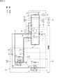
図1は、本発明の一実施形態に係る作業車両の側断面図である。図1において、本実施形態の作業車両は、運転室1aの後方の車体10上に塵芥収集機器(作業機器)を架装した塵芥収集車1からなる。車体10は、シャシフレーム11と、このシャシフレーム11上に載置して固定されたサブフレーム12とを有している。
Hereinafter, preferred embodiments of the present invention will be described with reference to the accompanying drawings.
[overall structure]
FIG. 1 is a side sectional view of a work vehicle according to an embodiment of the present invention. In FIG. 1, the work vehicle of the present embodiment includes a
塵芥収集車1は、上記塵芥収集機器として、サブフレーム12上に搭載された塵芥収容箱2と、塵芥収容箱2の後方に連設して設けられた塵芥投入箱3とを備えている。塵芥収容箱2の後面には、開口部2aが形成されている。塵芥投入箱3の後部には、塵芥が投入される投入口3aが形成されており、この投入口3aを上下にスライドして開閉する蓋3bが設けられている。塵芥投入箱3の前方下部には、塵芥投入箱3に投入された塵芥を塵芥収容箱2に収容するための開口3dが設けられている。
The
塵芥投入箱3は、上部に設けられた支点3fを中心に回動可能であり、これによって塵芥収容箱2に対しての開閉動作が可能である。塵芥投入箱3は、図の実線で示すように塵芥収容箱2の開口部2aを閉鎖する閉鎖位置と、図の二点鎖線で示すように上方回動により上記開口部2aを開放して塵芥を排出することができる開放位置との間で回動するようになっている。
The
次に、塵芥投入箱3内に設けられている積込装置Tについて説明する。塵芥投入箱3の左右の側壁3cには、押込シリンダ112のシリンダ側基端部112aが軸着されており、これにより押込シリンダ112は回動可能である。また、左右の側壁3cには、押込板108が支軸113を中心として回動可能に取り付けられている。押込板108は、図示のような側面形状の左右の部材間を車幅方向に延びるプレート等(図示省略)により接続して一体化したものである。
Next, the loading device T provided in the
押込板108の上端部と押込シリンダ112のピストンロッド先端部とは、ピン114により互いに接続されており、これにより、押込シリンダ112が伸長駆動すると、当該押込シリンダ112自身が図の反時計回り方向に回動しながら押込板108を図の時計回り方向に回動させ、図の実線で示す状態となる。また、その状態から押込シリンダ112が収縮駆動すると、当該押込シリンダ112自身が図の時計回り方向に回動しながら押込板108を図の反時計回り方向に回動させ、図の二点鎖線で示す状態となる。
The upper end of the
左右の側壁3cには、図示の側面形状で車幅方向に延びる回転板115が支軸116を中心として回転自在に取り付けられている。回転板115は、図の時計回り方向が通常回転方向である。塵芥投入箱3の内部底面3eは、回転板115の先端の回動軌跡に沿って円弧状に形成されている。
On the left and right side walls 3c, a
上記のように構成された積込装置Tにおいては、塵芥投入箱3内に塵芥が投入されると、回転板115は塵芥をかき込みながら図示の位置(9時の位置)まで上昇する。そして、回転板115が図示の位置に来たとき、押込板108が二点鎖線の位置から実線の位置まで図の時計回り方向に回動して、回転板115の上に載っている塵芥を塵芥収容箱2に押し込む。その後、押込板108は、回転板115が12時の位置を超える頃から図の反時計回り方向に回動し始め、次の押込動作開始までには元の位置(二点鎖線の位置)に戻っている。このような周期的動作が、1サイクル又は連続サイクルで行われる。
In the loading device T configured as described above, when dust is thrown into the
一方、塵芥収容箱2の下方にはダンプシリンダ(排出駆動手段)119が設けられており、そのシリンダ側基端部119aはサブフレーム12に軸着されている。また、ピストンロッド側先端部119bは塵芥収容箱2の下面に軸着されている。塵芥収容箱2の後端下部は、支軸120を介してサブフレーム12上に上下回動可能に支持されており、ダンプシリンダ119を伸縮駆動させることにより、塵芥収容箱2を図3(c)に示す傾動位置と図3(a)に示す着床位置との間で上下回動可能である。したがって、塵芥収容箱2内に積み込まれた塵芥は、ダンプシリンダ119を伸長駆動させて塵芥収容箱2を車体10に対して上方回動(傾動)させることにより、自重により開口部2aから外部へ排出される。
On the other hand, a dump cylinder (discharge driving means) 119 is provided below the
図2は、塵芥収集車1の背面図である。塵芥投入箱3の左右両端に配置された一対のスイングシリンダ(投入箱駆動手段)20は、上端が塵芥収容箱2側に取り付けられ、下端が塵芥投入箱3に取り付けられている。このスイングシリンダ20を伸長駆動させると塵芥投入箱3が上方回動(開放)され(図3(b)参照)、収縮駆動させると塵芥投入箱3が下方回動(閉鎖)される(図3(a)参照)。
FIG. 2 is a rear view of the
以上の構成により、図3(a)に示す走行状態(塵芥投入箱3が閉鎖位置にあり、かつ塵芥収容箱2が着床位置にある状態)から、塵芥収容箱2内に積み込まれた塵芥を外部に排出する排出作業を行う際には、まず、スイングシリンダ20を伸長駆動させて塵芥投入箱3を上方回動させる。これにより、塵芥投入箱3は、図3(b)に示すように、開放位置に到達する。この状態から、ダンプシリンダ119を伸縮駆動させて塵芥収容箱2を着床位置から上方回動させる。これにより、塵芥収容箱2は、図3(c)に示すように傾動位置まで上方回動した状態となり、塵芥収容箱2内に塵芥は自重により開口部2aから外部に排出される。
With the above configuration, the dust loaded in the
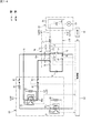
[油圧回路]
図4は、上記押込シリンダ112、ダンプシリンダ119、スイングシリンダ20、及び油圧モータ117に関する油圧回路図である。この油圧回路は、オイルタンク21、油圧ポンプ22、押込シリンダ用電磁切換弁124、油圧モータ用電磁切換弁125、ダンプシリンダ用電磁切換弁126、スイングシリンダ用電磁切換弁(テールゲートロック用電磁切換弁を兼用)27、切換弁28、テールゲートロック(シリンダ)31、その他圧力制御弁196〜199、逆止弁29,129a〜129f、フィルタ30等を図示のように接続して構成されている。
[Hydraulic circuit]
FIG. 4 is a hydraulic circuit diagram relating to the
油圧モータ117は、回転板115を回動させるものであり、押込シリンダ112と共に積込装置Tを駆動する積込駆動手段171を構成している。油圧ポンプ22には電動モータ23が接続されており、電動モータ23により油圧ポンプ22を駆動して作動油を吐出することにより、投入箱駆動手段(スイングシリンダ)20、排出駆動手段(ダンプシリンダ)119、及び積込駆動手段171をそれぞれ駆動させるようになっている。したがって、電動モータ23は、塵芥収集機器(作業機器)を駆動する作業用駆動部D2の駆動本体部として機能する。
The
油圧モータ用電磁切換弁125のソレノイド125nが励磁されると油圧モータ117が正転駆動して回転板115が図1の時計回り方向に回動する。そして、油圧モータ用電磁切換弁125のソレノイド125rが励磁されると油圧モータ117が逆転駆動して回転板115が図1の反時計回り方向に回動する。
When the
押込シリンダ用電磁切換弁124のソレノイド124sが励磁されると押込シリンダ112が収縮駆動し、ソレノイド124eが励磁されると押込シリンダ112が伸長駆動する。
ダンプシリンダ用電磁切換弁126のソレノイド126sが励磁されるとダンプシリンダ119が収縮駆動し、ソレノイド126eが励磁されるとダンプシリンダ119が伸長駆動する。
When the
When the
塵芥投入箱3が閉鎖位置にあるとき(図1の実線)、スイングシリンダ20は最も収縮した状態にあり、スイングシリンダ用電磁切換弁27は中立位置にある。なお、切換弁28は図4に示された位置にある。この状態からスイングシリンダ用電磁切換弁27のソレノイド27eが励磁されると、テールゲートロック31がロック解除方向に動作し、スイングシリンダ20が伸長駆動して塵芥投入箱3が上方回動する。
When the
スイングシリンダ用電磁切換弁27のソレノイド27eが消磁され、かつ、切換弁28が励磁されると、塵芥投入箱3の自重によりスイングシリンダ20内の作動油が切換弁28およびスイングシリンダ用電磁弁27を介してオイルタンク21に戻される。これにより、スイングシリンダ20が収縮駆動して塵芥投入箱3が下方回動する。また、塵芥投入箱3が閉鎖位置に達した後、スイングシリンダ用電磁弁27のソレノイド27sが励磁されると、テールゲートロック31がロック動作し、塵芥投入箱3が閉鎖位置でロックされる。その後、ソレノイド27sは消磁されるが、逆止弁29によりテールゲートロック31のロック状態は維持される。
When the
[スイッチボックス]
図5は、運転室1a内に設けられているスイッチボックスSB1の平面図である。スイッチボックスSB1には、メインスイッチ34、排出スイッチ35、かき出しスイッチ37、メインランプ38、及びロックランプ39が設けられている。
メインスイッチ34は、「積込」、「OFF」、及び「排出」のいずれかの位置を選択することができ、手を離しても選択した位置に保持されるタイプのスイッチである。排出スイッチ35は、「排出」、「OFF」、及び「戻し」のいずれかの位置を選択することができ、手を離すと「OFF」の位置に戻るタイプのスイッチである。
[Switch box]
FIG. 5 is a plan view of the switch box SB1 provided in the driver's cab 1a. The switch box SB1 is provided with a
The
メインスイッチ34を「積込」に切り替え操作すると、押込シリンダ112及び油圧モータ117の駆動が許容され、ダンプシリンダ119及びスイングシリンダ20の駆動が規制される。これにより、後述するスイッチボックスSB2,SB3のスイッチ42〜44の操作が可能となる。
一方、メインスイッチ34を「排出」に切り替え操作すると、ダンプシリンダ119及びスイングシリンダ20の駆動が許容され、押込シリンダ112及び油圧モータ117の駆動が規制される。これにより、排出スイッチ35の切り替え操作が可能となる。
When the
On the other hand, when the
メインスイッチ34を「排出」に切り替え操作した状態で、排出スイッチ35を「排出」に切り替え操作すると、スイングシリンダ用電磁切換弁27のソレノイド27eが励磁された後、ダンプシリンダ用電磁切換弁126のソレノイド126eが励磁される。これにより、図3(a)〜(c)の順に示すように、スイングシリンダ20が伸長駆動して塵芥投入箱3が上方回動した後、ダンプシリンダ119が自動的に伸長駆動して塵芥収容箱2が傾動位置まで上方回動する。
When the
この状態から、排出スイッチ35を「戻し」に切り替え操作すると、ダンプシリンダ用電磁切換弁126のソレノイド126sが励磁された後、スイングシリンダ用電磁切換弁27のソレノイド27eが消磁されるとともに切換弁28が励磁される。これにより、図3(c)〜(a)の順に示すように、ダンプシリンダ119が収縮駆動して塵芥収容箱2が自重により着床位置まで下方回動した後、スイングシリンダ20が自動的に収縮駆動して塵芥投入箱3が下方回動する。
When the
かき出しスイッチ37は、「自動」および「手動」のいずれか一方を選択することができ、手を離しても選択した位置に保持することができるタイプのスイッチである。かき出しスイッチ37を「自動」に選択すると、塵芥投入箱3を上方回動位置まで回動させると自動的に積込と同様の動作が行われ、塵芥投入箱3内に残留している塵芥を取り除くことができる。
The scraping
メインランプ38は、スイッチボックスSB1の各スイッチ操作が可能な状態のときに点灯するようになっている。ロックランプ39は、テールゲートロック31がロック状態のときに点灯するようになっている。スイッチボックスSB1のメインスイッチ34、排出スイッチ35及びかき出しスイッチ37は、制御部90(図6参照)に接続されている。なお、図6では、説明の便宜上、排出スイッチ35及びかき出しスイッチ37の図示を省略している。
The
図2において、塵芥投入箱3の左右両側壁3cの後部には、それぞれスイッチボックスSB2,SB3が設けられている。本実施形態では、スイッチボックスSB2は、図の左側の側壁3cに設けられており、スイッチボックスSB3は、図の右側の側壁3cに設けられている。スイッチボックスSB2,SB3の各スイッチは、上述のようにメインスイッチ34を「積込」に切り替え操作したときに操作可能となる。
In FIG. 2, switch boxes SB2 and SB3 are provided at the rear portions of the left and right side walls 3c of the
スイッチボックスSB2の側面には、押込板108及び回転板115の動作として「連続サイクル」又は「1サイクル」のどちらかの動作モードに選択するための動作選択スイッチ42が設けられている。スイッチボックスSB2の正面には、各動作モードで積込動作を開始させるための積込スイッチ(積込操作手段)43、連続サイクル動作を停止させるための停止スイッチ44がそれぞれ設けられている。なお、停止スイッチ44は、スイッチボックスSB3にも設けられている。
On the side surface of the switch box SB2, an
積込スイッチ43は、押込シリンダ112及び油圧モータ117をそれぞれ伸縮駆動させる操作信号を出力する操作スイッチである。なお、その他のスイッチについては、緊急時にのみ用いるスイッチ等であり、詳細な説明は省略する。なお、スイッチボックスSB2,SB3の各スイッチ42〜44も、制御部90(図6参照)に接続されている。なお、図6では、説明の便宜上、各スイッチ42〜44の図示を省略している。
The
[バッテリ]
図1において、塵芥収集車1は、キャブバックスペースS(運転室1aと塵芥収容箱2との間)のサブフレーム12上に搭載されたバッテリ4を動力源として、車両走行用駆動部D1の電動モータ5(図6参照)を駆動して走行するEVである。このバッテリ4は、塵芥収集機器を駆動する上記電動モータ23(作動用駆動部D2)の動力源も兼ねている。本実施形態のバッテリ4は、サブフレーム12に対して着脱自在に取り付けられており、サブフレーム12から取り外して外部の充電装置(図示省略)に接続することで充電されるようになっている。
[Battery]
In FIG. 1, the
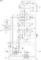
[電気回路]
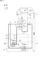
図6は、塵芥収集車1の電気回路図である。図6において、バッテリ4(電圧値は例えば400V)には、第1プラス側電路Lp1及び第1マイナス側電路Ln1が接続されている。第1プラス側電路Lp1及び第1マイナス側電路Ln1の各下流端には分岐回路50が接続されている。分岐回路50は、3個のプラス側接続端51p,52p,53pと、3個のマイナス側接続端51n,52n,53nとを備えている。
[electric circuit]
FIG. 6 is an electric circuit diagram of the
プラス側接続端51p及びマイナス側接続端51nには、それぞれ第1プラス側電路Lp1及び第1マイナス側電路Ln1が接続されており、プラス側接続端51pは、バッテリ4から第1プラス側電路Lp1を介して電力が入力される入力端として機能する。
他の2個のプラス側接続端52p,53pは、プラス側接続端51pから入力された電力を分岐して出力する第1出力端及び第2出力端として機能する。
The first positive side electric circuit Lp1 and the first negative side electric circuit Ln1 are connected to the positive
The other two positive side connection ends 52p and 53p function as a first output end and a second output end for branching and outputting the power input from the positive
プラス側接続端52p(第1出力端)及びマイナス側接続端52nには、それぞれ第2プラス側電路Lp2及び第2マイナス側電路Ln2が接続されており、これらの電路Lp2,Ln2の各下流端には車両走行用駆動部D1が接続されている。
プラス側接続端53p(第2出力端)及びマイナス側接続端53nには、それぞれ第3プラス側電路Lp3及び第3マイナス側電路Ln3が接続されており、これらの電路Lp3,Ln3の各下流端には作業用駆動部D2が接続されている。また、第3プラス側電路Lp3の途中のプラス側バイパス接続点P1と、第3マイナス側電路Ln3の途中のマイナス側バイパス接続点P2とは、バイパス電路Lb10により接続されている。
A second positive side electric line Lp2 and a second negative side electric line Ln2 are connected to the positive
A third positive side electric circuit Lp3 and a third negative side electric line Ln3 are connected to the positive
以上により、分岐回路50は、バッテリ4から入力された電力を分岐して車両走行用駆動部D1と作業用駆動部D2とに出力する。これにより、車両走行用駆動部D1および作業用駆動部D2は、バッテリ4から電力供給を受けて駆動する。
As described above, the
車両走行用駆動部D1は、インバータ6と、このインバータ6に接続された上記電動モータ5とを備えている。インバータ6は、その内部に、第2プラス側電路Lp2及び第2マイナス側電路Ln2に接続されたコンデンサ6a(例えば電圧値は200V)を有している。コンデンサ6aは、交流の電動モータ5を安定して駆動させるために、電動モータ5に供給する電力を充電する。
The vehicle traveling drive unit D1 includes an
作業用駆動部D2は、インバータ24と、このインバータ24に接続された上記電動モータ23(駆動本体部)とを備えている。インバータ24は、その内部に、第3プラス側電路Lp3及び第3マイナス側電路Ln3に接続されたコンデンサ24a(例えば電圧値は200V)を有している。コンデンサ24aは、交流の電動モータ23を安定して駆動させるために、電動モータ23に供給する電力を充電する。したがって、コンデンサ6aは、バッテリ4から電力供給を受けて充電する充電部として機能し、電動モータ23は、充電されたコンデンサ6aから電力供給を受けて塵芥収集機器を駆動する。
The work drive unit D2 includes an
本実施形態では、第1プラス側電路Lp1及び第3プラス側電路Lp3は、バッテリ4のプラス側とコンデンサ24aのプラス側とを接続している接続電路L10のプラス側接続電路Lp10を構成している。また、第1マイナス側電路Ln1及び第3マイナス側電路Ln3は、バッテリ4のマイナス側とコンデンサ24aのマイナス側とを接続している接続電路L10のマイナス側接続電路Ln10を構成している。そして、プラス側接続電路Lp10、マイナス側接続電路Ln10、及びバイパス電路Lb10は、バッテリ4とコンデンサ24aとを接続する接続電路L10を構成している。
In the present embodiment, the first positive side electric circuit Lp1 and the third positive side electric circuit Lp3 constitute a positive side connection electric circuit Lp10 of the connection electric circuit L10 connecting the positive side of the
[車両走行用リレー回路]
第1プラス側電路Lp1及び第1マイナス側電路Ln1の途中には、これらの電路Lp1,Ln1を開閉可能な車両走行用リレー回路60が設けられている。本実施形態の車両走行用リレー回路60は、第1リレー61、第2リレー62、第3リレー63、及び制限抵抗64を備えている。
[Relay circuit for vehicle running]
A vehicle traveling
第1リレー61は、第1プラス側電路Lp1の途中に設けられている。制限抵抗64及び第2リレー62は、第1プラス側電路Lp1の途中において、第1リレー61に対して並列に接続され、かつ上流側(バッテリ4側。以下、同様)からこの順に互いに直列に接続されている。第1及び第2リレー61,62は、第1プラス側電路Lp1を開閉するようになっている。第3リレー63は第1マイナス側電路Ln1の途中に設けられ、当該電路Lp1を開閉するようになっている。第1〜第3リレー61〜63は、制御部90(図6参照)に接続されており、当該制御部90よって開閉制御される。
The
車両走行用リレー回路60では、図示を省略しているが、バッテリ4を収容している筐体内に設けられたスイッチをオン操作すると、制御部90により各リレー61〜63が開閉制御され、バッテリ4から車両走行用駆動部D1に電力が供給される。
具体的には、前記スイッチをオン操作すると、車両走行用リレー回路60は、各リレー61〜63が全て開いている状態から、まず第3リレー63を閉じた後に第2リレー62を閉じるように制御される。
Although not shown in the vehicle running
Specifically, when the switch is turned on, the vehicle running
そうすると、バッテリ4のプラス側から、第1プラス側電路Lp1(制限抵抗64,閉じている第2リレー62)、分岐回路50(プラス側接続端51p,52p)、第2プラス側電路Lp2、インバータ6(コンデンサ6a)、第2マイナス側電路Ln2、分岐回路50(マイナス側接続端52n,51n)、第1マイナス側電路Ln1(閉じている第3リレー63)を通って、バッテリ4に戻る電力経路が形成される。これにより、インバータ6のコンデンサ6aの充電が開始される。
Then, from the positive side of the
第2リレー62を閉じてからコンデンサ6aの充電が完了するまでに必要な時間(例えば2秒)が経過すると、次に、車両走行用リレー回路60は、制御部90により第1リレー61を閉じた後に第2リレー62を開けるように制御される。
When the time required (for example, 2 seconds) from closing the
そうすると、バッテリ4のプラス側から、第1プラス側電路Lp1(閉じている第1リレー61)、分岐回路50(プラス側接続端51p,52p)、第2プラス側電路Lp2、インバータ6(コンデンサ6a)、第2マイナス側電路Ln2、分岐回路50(マイナス側接続端52n,51n)、第1マイナス側電路Ln1(閉じている第3リレー63)を通って、バッテリ4に戻る電力経路が形成される。これにより、第1プラス側電路Lp1及び第1マイナス側電路Ln1は閉じた状態となり、バッテリ4から車両走行用駆動部D1の電動モータ5に電力が安定して供給される。
Then, from the positive side of the
この状態から車両走行用駆動部D1への電力供給を遮断する場合には、前記キースイッチをオフ操作する。そうすると、車両走行用リレー回路60は、第1リレー61を開けた後に第3リレー63を開けるように制御される。これにより、全てのリレー61〜63が開いた状態、すなわち第1プラス側電路Lp1及び第1マイナス側電路Ln1は開いた状態となり、バッテリ4から車両走行用駆動部D1への電力の供給が遮断される。
When the power supply to the vehicle traveling drive unit D1 is cut off from this state, the key switch is turned off. Then, the vehicle traveling
[作業用リレー回路]
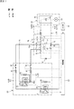
第3プラス側電路Lp3及び第3マイナス側電路Ln3の途中には、これらの電路Lp3,Ln3を開閉可能な作業用リレー回路70が設けられている。本実施形態の作業用リレー回路70は、第1接続用リレー71、第2接続用リレー72、第3接続用リレー73、第4接続用リレー74、第5接続用リレー75、ヒューズ76、及び制限抵抗(接続用抵抗)77を備えている。本実施形態の作業用リレー回路70は、上記接続電路L10を開閉可能なリレー回路として機能する。
[Working relay circuit]
A
ヒューズ76及び第1接続用リレー71は、第3プラス側電路Lp3のプラス側バイパス接続点P1よりも上流側において、上流側からこの順に直列に接続されている。第2接続用リレー72及び制限抵抗77は、第3プラス側電路Lp3のプラス側バイパス接続点P1よりも下流側(コンデンサ24a側。以下、同様)において、上流側からこの順に直列に接続されている。なお、第2接続用リレー72及び制限抵抗77は、下流側からこの順に直列に接続されていてもよい。
The
第3接続用リレー73は、第3プラス側電路Lp3におけるプラス側バイパス接続点P1よりも下流側で、第1接続用リレー71に対して直列に接続され、かつ第2接続用リレー72及び制限抵抗77に対して並列に接続されている。これにより、プラス側バイパス接続点P1は、第2接続用リレー72及び第3接続用リレー73の上流側の並列接続点P3と、第1接続用リレー71との間に位置している。第1〜第3接続用リレー71〜73は、第3プラス側電路Lp3を開閉するようになっている。
The
第4接続用リレー74は、第3マイナス側電路Ln3のマイナス側バイパス接続点P2よりも上流側に設けられ、当該電路Ln3を開閉するようになっている。第5接続用リレー75は、バイパス電路Lb10の途中に設けられ、当該電路Lb10を開閉するようになっている。第1〜第5接続用リレー71〜75は、制御部90(図6参照)に接続されており、当該制御部90によって開閉制御される。
The
作業用リレー回路70では、車両走行用リレー回路60により第1プラス側電路Lp1及び第1マイナス側電路Ln1を閉じた状態、つまり、バッテリ4から、これらの電路Lp1,Ln1及び分岐回路50を介して、第3プラス側電路Lp3及び第3マイナス側電路Ln3に電力を供給可能な状態において、スイッチボックスSB1のメインスイッチ34(図5参照)を「積込」又は「排出」に切り替え操作すると、制御部90により各接続用リレー71〜74が開閉制御され、バッテリ4から作業用駆動部D2に電力が供給される。
In the
具体的には、車両走行用リレー回路60により第1プラス側電路Lp1及び第1マイナス側電路Ln1を閉じた状態において、メインスイッチ34を「OFF」から「積込」又は「排出」に切り替え操作すると、作業用リレー回路70は、各接続用リレー71〜75が全て開いている状態から、制御部90により、第4接続用リレー74および第2接続用リレー72をこの順に閉じた後、第1接続用リレー71を閉じるように制御される。
Specifically, the operation of switching the
そうすると、バッテリ4のプラス側から、第1プラス側電路Lp1(閉じている第1リレー61)、分岐回路50(プラス側接続端51p,53p)、第3プラス側電路Lp3(ヒューズ76,閉じている第1接続用リレー71および第2接続用リレー72,制限抵抗77)、インバータ24(コンデンサ24a)、第3マイナス側電路Ln3(閉じている第4接続用リレー74)、分岐回路50(マイナス側接続端53nおよび51n)、第1マイナス側電路Ln1(閉じている第3リレー63)を通って、バッテリ4に戻る電力経路が形成される(図34参照)。これにより、インバータ24のコンデンサ24aの充電が開始される。
Then, from the positive side of the
第1接続用リレー71を閉じてからコンデンサ24aの充電が完了するまでに必要な時間(例えば2秒)が経過すると、次に、作業用リレー回路70は、制御部90により第3接続用リレー73を閉じた後に第2接続用リレー72を開けるように制御される。
When the time required (for example, 2 seconds) has elapsed from the closing of the
そうすると、バッテリ4のプラス側から、第1プラス側電路Lp1(閉じている第1リレー61)、分岐回路50(プラス側接続端51p,53p)、第3プラス側電路Lp3(ヒューズ76,閉じている第1接続用リレー71および第3接続用リレー73)、インバータ24(コンデンサ24a)、第3マイナス側電路Ln3(閉じている第4接続用リレー74)、分岐回路50(マイナス側接続端53nおよび51n)、第1マイナス側電路Ln1(閉じている第3リレー63)を通って、バッテリ4に戻る電力経路が形成される(図35参照)。
Then, from the positive side of the
これにより、第3プラス側電路Lp3及び第3マイナス側電路Ln3が閉じた状態となり、バッテリ4から作業用駆動部D2の電動モータ23に電力が安定して供給される。したがって、本実施形態のメインスイッチ34は、作業用駆動部D2の電動モータ23に電力を供給するための給電操作スイッチとして機能する。
As a result, the third positive side electric circuit Lp3 and the third negative side electric circuit Ln3 are closed, and electric power is stably supplied from the
この状態から作業用駆動部D2への電力供給を遮断する場合には、スイッチボックスSB1のメインスイッチ34(図5参照)を「OFF」に切り替え操作する。そうすると、作業用リレー回路70は、制御部90により各接続用リレー71〜75が開閉制御され、バッテリ4から作業用駆動部D2への電力供給が遮断される。
When the power supply to the work drive unit D2 is cut off from this state, the main switch 34 (see FIG. 5) of the switch box SB1 is switched to "OFF". Then, in the
具体的には、メインスイッチ34を「OFF」に切り替え操作すると、作業用リレー回路70は、第1接続用リレー71、第3接続用リレー73及び第4接続用リレー74が全て閉じており、第2接続用リレー72及び第5接続用リレー75が全て開いている状態から、制御部90により、第1接続用リレー71及び第3接続用リレー73をこの順に開けるように制御される。そして、制御部90により、さらに第5接続用リレー75及び第2接続用リレー74をこの順に閉じた後、第4接続用リレー74を開けるように制御される。
Specifically, when the
そうすると、インバータ24のコンデンサ24aのプラス側から、第3プラス側電路Lp3(制限抵抗77,閉じている第2接続用リレー72,並列接続点P3からプラス側バイパス接続点P1までの間)、バイパス電路Lb10(閉じている第5接続用リレー75)、第3マイナス側電路Ln3(マイナス側バイパス接続点P2よりも下流側)を通って、コンデンサ24aに戻る電力経路が形成される(図45参照)。これにより、コンデンサ24aの放電が開始される。
Then, from the positive side of the
第4接続用リレー74を開けてからコンデンサ24aの放電が完了するまでに必要な時間(例えば2秒)が経過すると、次に、作業用リレー回路70は、制御部90により第2接続用リレー72及び第5接続用リレー75をこの順に開けるように制御される。これにより、全てのリレー71〜75が開いた状態、すなわち第3プラス側電路Lp3及び第3マイナス側電路Ln3が開いた状態となり、バッテリ4から作業用駆動部D2への電力供給が遮断される。
When the time (for example, 2 seconds) required from opening the
したがって、本実施形態のメインスイッチ34は、作業用駆動部D2の電動モータ23への電力供給を遮断するための遮断操作スイッチとして機能する。なお、本実施形態のメインスイッチ34は、上記のように電動モータ23に電力を供給するための給電操作スイッチとしても機能するが、給電操作スイッチと遮断操作スイッチとを別々に設けてもよい。
Therefore, the
[検知回路]
接続電路L10の途中には、作業用リレー回路70の各接続用リレー71〜75の動作不良を点検するための検知回路80が接続されている。検知回路80は、第1検知用電路L5、第2検知用電路L6、第1通電検知部81、第1検知用リレー82、第1直列抵抗83、第1並列抵抗84、第2通電検知部85、第2検知用リレー86、第2直列抵抗87、及び第2並列抵抗88を備えている。本実施形態では、第1検知用電路L5及び第2検知用電路L6は、接続電路L10の途中に接続された検知用電路L20を構成している。
[Detection circuit]
A
第1検知用電路L5は、第3プラス側電路Lp3における第1接続用リレー71とプラス側バイパス接続点P1との間の第1プラス側接続点P4、及び第3マイナス側電路Ln3における第4接続用リレー74とマイナス側バイパス接続点P2との間のマイナス側接続点P5を接続している。
第2検知用電路L6は、第1検知用電路L5の途中である第2プラス側接続点P6、及び第3プラス側電路Lp3におけるヒューズ76と第1接続用リレー71との間の第3プラス側接続点P7を接続している。
The first detection electric circuit L5 is a first positive side connection point P4 between the
The second detection electric circuit L6 is a third plus between the
第1検知用電路L5の第2プラス側接続点P6とマイナス側接続点P5との間には、第2プラス側接続点P6側から順に、第1検知用リレー82、第1直列抵抗83及び第1通電検知部81が直列に接続されている。第1検知用リレー82は、第1検知用電路L5を開閉するようになっている。なお、第1検知用リレー82は、第1通電検知部81よりもマイナス側接続点P5側に配置されていてもよい。
Between the second positive side connection point P6 and the negative side connection point P5 of the first detection electric circuit L5, the
第1検知用電路L5の第1直列抵抗83よりもマイナス側接続点P5側には、第1並列抵抗84が、第1直列抵抗83及び第1検知用リレー82に対して直列に接続されているとともに、第1通電検知部81に対して並列に接続されている。第1直列抵抗83及び第1並列抵抗84は、第1通電検知部81の検知精度を高めるために、第1検知用電路L5を流れる電気信号を整流するものである。
A first
第1通電検知部81は、例えばフォトカプラからなり、発光ダイオード等の発光素子81aと、フォトトランジスタ等の受光素子81bとを、外部からの光を遮断するケース(図示省略)内に収容して構成されている。受光素子81bは、第1〜第5接続用リレー71〜75を開閉制御する制御部90に接続されている。
The first
第1通電検知部81は、第1検知用電路L5が通電している場合、発光素子81aに入力された電気信号を光に変換し、その光を受光素子81bが電気信号に戻して制御部90に出力する。また、第1通電検知部81は、第1検知用電路L5が通電していない場合、発光素子81aには電気信号が入力されないため、受光素子81bも電気信号を制御部90に出力しない。
When the first detection electric circuit L5 is energized, the first
したがって、本実施形態の第1通電検知部81は、受光素子81bが電気信号を出力することで第1検知用電路L5の通電を検知した状態となり、受光素子81bが電気信号を出力しないことで第1検知用電路L5の非通電を検知した状態となる。このように、第1通電検知部81は、第1検知用電路L5に対して電気的に絶縁しながら、当該電路L5の通電状態を検知することができる。
Therefore, the first
第2検知用電路L6の第2プラス側接続点P6と第3プラス側接続点P7との間には、第2プラス側接続点P6側から順に、第2通電検知部85、第2直列抵抗87及び第2検知用リレー86が直列に接続されている。第2検知用リレー86は、第2検知用電路L6を開閉するようになっている。なお、第2検知用リレー86は、第2通電検知部85よりも第2プラス側接続点P6側に配置されていてもよい。
Between the second positive side connection point P6 and the third positive side connection point P7 of the second detection electric circuit L6, the second
第2検知用電路L6の第2直列抵抗87よりも第2プラス側接続点P6側には、第2並列抵抗88が、第2直列抵抗87及び第2検知用リレー86に対して直列に接続されているとともに、第2通電検知部85に対して並列に接続されている。第2直列抵抗87及び第2並列抵抗88は、第2通電検知部85の検知精度を高めるために、第2検知用電路L6を流れる電気信号を整流するものである。
A second
第2通電検知部85は、例えば第1通電検知部81と同様にフォトカプラからなり、発光ダイオード等の一対の発光素子85aと、フォトトランジスタ等の受光素子85bとを、外部からの光を遮断するケース(図示省略)内に収容して構成されている。受光素子85bは、第1〜第5接続用リレー71〜75を開閉制御する制御部90に接続されている。
The second
第2通電検知部85は、第2検知用電路L6が通電している場合、発光素子85aに入力された電気信号を光に変換し、その光を受光素子85bが電気信号に戻して制御部90に出力する。また、第2通電検知部85は、第2検知用電路L6が通電していない場合、発光素子85aには電気信号が入力されないため、受光素子85bも電気信号を制御部90に出力しない。
When the second detection electric circuit L6 is energized, the second
したがって、本実施形態の第2通電検知部85は、受光素子85bが電気信号を出力することで第2検知用電路L6の通電を検知した状態となり、受光素子85aが電気信号を出力しないことで第2検知用電路L6の非通電を検知した状態となる。このように、第2通電検知部85は、第2検知用電路L6に対して電気的に絶縁しながら、当該電路L6の通電状態を検知することができる。
Therefore, the second
[制御部]
制御部90は、CPUやメモリ等を有するものであり、第1及び第2通電検知部81,85の各検知結果に基づいて、作業用リレー回路70の複数の接続用リレー71〜75、及び検知回路80の検知用リレー82,86のそれぞれに動作不良が発生しているか否かを判定する不良判定制御を行う。
[Control unit]
The
具体的には、制御部90は、車両のキースイッチ(図示省略)がオン操作されたときの操作信号が入力されると、各接続用リレー71〜75及び各検知用リレー82,86の動作不良を判定する「初期不良判定制御」を行う。
Specifically, when the operation signal when the vehicle key switch (not shown) is turned on is input, the
初期不良判定制御において、制御部90は、第1初期不良判定(工程a1)、第2初期不良判定(工程a2)、第3初期不良判定(工程a3)、第4初期不良判定(工程a4)、第5初期不良判定(工程a5)、第6初期不良判定(工程a6)、第7初期不良判定(工程a7)、及び第8初期不良判定(工程a8)をこの順に実行する。これらの工程a1〜a8の詳細については後述する。
In the initial defect determination control, the
制御部90は、メインスイッチ34が「OFF」から「積込」又は「排出」に切り替え操作されたときの操作信号が入力されると、上記のようにバッテリ4から電動モータ23に電力を供給するために各接続用リレー71〜74を開閉する給電制御を行うが、その給電制御を行いながら、所定のリレー(本実施形態では、接続用リレー71〜75及び検知用リレー82,86)の動作不良を判定する「給電時不良判定制御」を行う。
When the operation signal when the
給電制御において、制御部90は、第1給電時不良判定(工程b1)、第2給電時不良判定(工程b2)、第1給電時リレー開閉(工程b3)、及び第2給電時リレー開閉(工程b4)をこの順に実行する。これらの工程b1〜b4の詳細については後述する。
In the power supply control, the
制御部90は、メインスイッチ34が「積込」又は「排出」から「OFF」に切り替え操作されたときの操作信号が入力されると、上記のようにバッテリ4から電動モータ23への電力供給を遮断するために各接続用リレー71〜75を開閉する遮断制御を行うが、その遮断制御を行いながら、所定のリレー(本実施形態では、接続用リレー71〜73及び検知用リレー81,82)の動作不良を判定する「遮断時不良判定制御」を行う。
When the operation signal when the
遮断時不良判定制御において、制御部90は、第1遮断時不良判定(工程c1)、第2遮断時不良判定(工程c2)、第1遮断時リレー開閉(工程c3)、及び第2遮断時リレー開閉(工程c4)をこの順に実行する。これらの工程c1〜c4の詳細については後述する。
In the shutoff failure determination control, the
[初期不良判定制御]
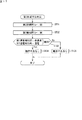
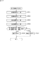
図7は、制御部90が実行する初期不良判定制御の処理内容を示すフローチャートである。以下、図7を参照しつつ、初期不良判定制御の処理手順について説明する。制御部90は、まず、車両のキースイッチがオン操作されたときの操作信号が入力されるのを待つ(ステップST1)。
[Initial defect judgment control]
FIG. 7 is a flowchart showing the processing contents of the initial failure determination control executed by the
制御部90は、前記操作信号が入力されると(ステップST1でYesの場合)、まず整数型の変数nの値を1として初期化する(ステップST2)。次に、制御部90は、初期不良判定制御の第n初期不良判定を行い(ステップST3)、その判定において判定対象のリレーに動作不良が発生しているという判定結果となったか否かを確認する(ステップST4)。
When the operation signal is input (Yes in step ST1), the
ステップST4の確認結果が肯定的である場合、制御部90は初期不良判定制御の処理を終了する。一方、ステップST4の確認結果が否定的である場合、制御部90は、変数nの値が8であるか否かを判定する(ステップST5)。
ステップST5の判定結果が否定的である場合、制御部90は、変数n=n+1として(ステップST6)、ステップST3に戻り、ステップST3〜ステップST5を再び行う。
If the confirmation result in step ST4 is affirmative, the
If the determination result in step ST5 is negative, the
このようにして、制御部90は、変数nの値が1から8になるまで、つまり第1初期不良判定から第8初期不良判定までをこの順に実行し、いずれかの判定結果が否定的である場合(接続用リレー71〜75又は検知用リレー82,86のいずれかに動作不良が発生している場合)には、次工程があっても、その時点で初期不良判定制御を終了する。例えば、制御部90は、第1初期不良判定の判定結果が否定的である場合には、その時点で第2〜第8給電時不良判定、後述するステップST7及びステップST8を行うことなく初期不良判定制御を終了する。
In this way, the
次に、第1〜第8初期不良判定について、この順に詳しく説明する。
図8は、第1初期不良判定を行う前における各リレーの開閉状態を示す電気回路図である。なお、図8以降の図面では、閉じているリレーは、その接点を黒色に塗りつぶして表示し、開いているリレーは、その接点を白抜きで表示する。
Next, the first to eighth initial failure determinations will be described in detail in this order.
FIG. 8 is an electric circuit diagram showing an open / closed state of each relay before the first initial failure determination is performed. In the drawings after FIG. 8, the closed relay is displayed by painting the contact in black, and the open relay is displayed by white.
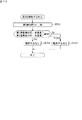
第1初期不良判定を行う前の状態では、作業用リレー回路70の接続用リレー71〜75は全て開いており、検知回路80の検知用リレー82,86も全て開いている。また、車両走行用リレー回路60では、リレー61,63は閉じており、リレー62は開いている。これにより、作業用リレー回路70を開閉制御することで、バッテリ4から電動モータ23への電力供給が可能な状態となっている。
In the state before the first initial failure determination is performed, all the connection relays 71 to 75 of the
図9は、制御部90が実行する第1初期不良判定(判定a1)の処理内容を示すフローチャートである。また、図10は、第1初期不良判定を実行したときの各リレーの開閉状態を示す電気回路図である。第1初期不良判定において、制御部90は、第4接続用リレー74を判定対象のリレーとして、当該リレーの動作不良を判定する。
FIG. 9 is a flowchart showing the processing contents of the first initial failure determination (determination a1) executed by the
具体的には、図9及び図10において、制御部90は、図8に示す状態から、第1検知用リレー82を閉じた後(ステップST11)、第2検知用リレー86を閉じる(ステップST12)。なお、図10以降の図面では、説明の便宜上、図6に示す分岐回路50、車両走行用リレー回路60及び車両走行用駆動部D1の図示を省略する。
Specifically, in FIGS. 9 and 10, the
次に、制御部90は、第1及び第2通電検知部81,85がいずれも非通電を検知したか否かを判定する(ステップST13)。そして、制御部90は、判定結果が肯定的である場合には、判定対象のリレー(ここでは第4接続用リレー74)に動作不良は発生していないと判定し(ステップST14)、判定結果が否定的である場合には、前記判定対象のリレーに動作不良が発生していると判定する(ステップST15)。
Next, the
ここで、第1初期不良判定の判定結果が否定的となる原因としては、第4接続用リレー74が閉じた状態で固着し、図12の太線で示す電力経路が形成されることで、第1及び第2通電検知部81,85がいずれも通電を検知している場合が考えられる。したがって、作業者は、例えば制御部のメモリ等に記憶された初期不良判定制御の履歴情報から、第1初期不良判定により初期不良判定制御が終了したことを確認することで、第4接続用リレー74の固着に起因した動作不良である可能性が高いと判断することができる。
Here, the reason why the determination result of the first initial failure determination is negative is that the
図11は、制御部90が実行する第2初期不良判定(判定a2)の処理内容を示すフローチャートである。また、図12は、第2初期不良判定を実行したときの各リレーの開閉状態を示す電気回路図である。第2初期不良判定において、制御部90は、第1〜第5接続用リレー71〜75、第1検知用リレー82、及び第2検知用リレー86のそれぞれを判定対象のリレーとして、当該リレーの動作不良を判定する。
FIG. 11 is a flowchart showing the processing contents of the second initial failure determination (determination a2) executed by the
具体的には、図11及び図12において、制御部90は、図10に示す状態から、第4接続用リレー74を閉じる(ステップST21)。次に、制御部90は、第1及び第2通電検知部81,85がいずれも通電を検知したか否かを判定する(ステップST22)。そして、制御部90は、判定結果が肯定的である場合には、前記判定対象のリレーに動作不良は発生していないと判定し(ステップST23)、判定結果が否定的である場合には、前記判定対象のリレーに動作不良が発生していると判定する(ステップST24)。
Specifically, in FIGS. 11 and 12, the
ここで、第2初期不良判定の判定結果が否定的となる原因としては、下記の原因a21〜a27のいずれかであると考えられる。
原因a21:図13に示すように、第1接続用リレー71が閉じた状態で固着し、図中の太線で示す電力経路が形成されることで、第1通電検知部81が通電を検知し、且つ第2通電検知部85が非通電を検知した状態となる。
原因a22:図14に示すように、第5接続用リレー75が閉じた状態で固着し、図中の太線で示す電力経路が形成されることで、第1通電検知部81が非通電を検知し、且つ第2通電検知部85が通電を検知した状態となる。
Here, it is considered that one of the following causes a21 to a27 is the cause of the negative determination result of the second initial defect determination.
Cause a21: As shown in FIG. 13, the
Cause a22: As shown in FIG. 14, the
原因a23:図15に示すように、第3接続用リレー73が閉じた状態で固着し、図中の太線で示す電力経路が形成されることで、第1通電検知部81が非通電を検知し、且つ第2通電検知部85が通電を検知した状態となる。
原因a24:図16に示すように、第2接続用リレー72が閉じた状態で固着し、図中の太線で示す電力経路が形成されることで、第1通電検知部81が非通電を検知し、且つ第2通電検知部85が通電を検知した状態となる。
Cause a23: As shown in FIG. 15, the
Cause a24: As shown in FIG. 16, the
原因a25:図12において、第4接続用リレー74が開いた状態で固着し、図中の太線で示す電力経路が形成されないことで、第1及び第2通電検知部81,85がいずれも非通電を検知した状態となる。
原因a26:図12において、第1検知用リレー82が開いた状態で固着し、図中の太線で示す電力経路が形成されないことで、第1及び第2通電検知部81,85がいずれも非通電を検知した状態となる。
原因a27:図12において、第2検知用リレー86が開いた状態で固着し、図中の太線で示す電力経路が形成されないことで、第1及び第2通電検知部81,85がいずれも非通電を検知した状態となる。
Cause a25: In FIG. 12, the
Cause a26: In FIG. 12, the
Cause a27: In FIG. 12, the
したがって、作業者は、例えば制御部のメモリ等に記憶された初期不良判定制御の履歴情報から、第2初期不良判定により初期不良判定制御が終了したことを確認することで、第1〜第5接続用リレー71〜75、第1検知用リレー82、及び第2検知用リレー86のいずれかの固着に起因した動作不良である可能性が高いと判断することができる。
Therefore, the operator confirms that the initial failure determination control has been completed by the second initial failure determination from the history information of the initial defect determination control stored in the memory of the control unit, for example, so that the first to fifth operations can be performed. It can be determined that there is a high possibility of malfunction due to sticking of any of the connection relays 71 to 75, the
図17は、制御部90が実行する第3初期不良判定(判定a3)の処理内容を示すフローチャートである。また、図18は、第3初期不良判定を実行したときの各リレーの開閉状態を示す電気回路図である。第3初期不良判定において、制御部90は、第2接続用リレー72を判定対象のリレーとして、当該リレーの動作不良を判定する。
FIG. 17 is a flowchart showing the processing contents of the third initial failure determination (determination a3) executed by the
具体的には、図17及び図18において、制御部90は、図12に示す状態から、第2接続用リレー72を閉じた後(ステップST31)、第1検知用リレー82を開ける(ステップST32)。次に、制御部90は、第1通電検知部81が非通電を検知し、且つ第2通電検知部85が通電を検知したか否かを判定する(ステップST33)。そして、制御部90は、判定結果が肯定的である場合には、前記判定対象のリレーに動作不良は発生していないと判定し(ステップST34)、判定結果が否定的である場合には、前記判定対象のリレーに動作不良が発生していると判定する(ステップST35)。
Specifically, in FIGS. 17 and 18, the
ここで、第3初期不良判定の判定結果が否定的となる原因としては、図18において、第2接続用リレー72が開いた状態で固着し、図中の太線で示す電力経路が形成されないことで、第1及び第2通電検知部81,85がいずれも非通電を検知している場合が考えられる。したがって、作業者は、例えば制御部のメモリ等に記憶された初期不良判定制御の履歴情報から、第3初期不良判定により初期不良判定制御が終了したことを確認することで、第2接続用リレー72の固着に起因した動作不良である可能性が高いと判断することができる。
Here, the reason why the determination result of the third initial failure determination is negative is that in FIG. 18, the
図19は、制御部90が実行する第4初期不良判定(判定a4)の処理内容を示すフローチャートである。また、図20は、第4初期不良判定を実行したときの各リレーの開閉状態を示す電気回路図である。第4初期不良判定において、制御部90は、第3接続用リレー73を判定対象のリレーとして、当該リレーの動作不良を判定する。
FIG. 19 is a flowchart showing the processing contents of the fourth initial failure determination (determination a4) executed by the
具体的には、図19及び図20において、制御部90は、図18に示す状態から、第3接続用リレー73を閉じた後(ステップST41)、第2接続用リレー72を開ける(ステップST42)。次に、制御部90は、第1通電検知部81が非通電を検知し、且つ第2通電検知部85が通電を検知したか否かを判定する(ステップST43)。そして、制御部90は、判定結果が肯定的である場合には、前記判定対象のリレーに動作不良は発生していないと判定し(ステップST44)、判定結果が否定的である場合には、前記判定対象のリレーに動作不良が発生していると判定する(ステップST45)。
Specifically, in FIGS. 19 and 20, the
ここで、第4初期不良判定の判定結果が否定的となる原因としては、図20において、第3接続用リレー73が開いた状態で固着し、図中の太線で示す電力経路が形成されないことで、第1及び第2通電検知部81,85がいずれも非通電を検知している場合が考えられる。したがって、作業者は、例えば制御部のメモリ等に記憶された初期不良判定制御の履歴情報から、第4初期不良判定により初期不良判定制御が終了したことを確認することで、第3接続用リレー73の固着に起因した動作不良である可能性が高いと判断することができる。
Here, the reason why the determination result of the fourth initial failure determination is negative is that in FIG. 20, the
図21は、制御部90が実行する第5初期不良判定(判定a5)の処理内容を示すフローチャートである。また、図22は、第5初期不良判定を実行したときの各リレーの開閉状態を示す電気回路図である。第5初期不良判定において、制御部90は、第5接続用リレー75を判定対象のリレーとして、当該リレーの動作不良を判定する。
FIG. 21 is a flowchart showing the processing contents of the fifth initial failure determination (determination a5) executed by the
具体的には、図21及び図22において、制御部90は、図20に示す状態から、第5接続用リレー75を閉じた後(ステップST51)、第3接続用リレー73を開ける(ステップST52)。次に、制御部90は、第1通電検知部81が非通電を検知し、且つ第2通電検知部85が通電を検知したか否かを判定する(ステップST53)。そして、制御部90は、判定結果が肯定的である場合には、前記判定対象のリレーに動作不良は発生していないと判定し(ステップST54)、判定結果が否定的である場合には、前記判定対象のリレーに動作不良が発生していると判定する(ステップST55)。
Specifically, in FIGS. 21 and 22, the
ここで、第5初期不良判定の判定結果が否定的となる原因としては、図22において、第5接続用リレー75が開いた状態で固着し、図中の太線で示す電力経路が形成されないことで、第1及び第2通電検知部81,85がいずれも非通電を検知している場合が考えられる。したがって、作業者は、例えば制御部のメモリ等に記憶された初期不良判定制御の履歴情報から、第5初期不良判定により初期不良判定制御が終了したことを確認することで、第5接続用リレー75の固着に起因した動作不良である可能性が高いと判断することができる。
Here, the reason why the determination result of the fifth initial failure determination is negative is that in FIG. 22, the
図23は、制御部90が実行する第6初期不良判定(判定a6)の処理内容を示すフローチャートである。また、図24は、第6初期不良判定を実行したときの各リレーの開閉状態を示す電気回路図である。第6初期不良判定において、制御部90は、第1検知用リレー82を判定対象のリレーとして、当該リレーの動作不良を判定する。
FIG. 23 is a flowchart showing the processing contents of the sixth initial failure determination (determination a6) executed by the
具体的には、図23及び図24において、制御部90は、図22に示す状態から、第5接続用リレー75を開ける(ステップST61)。次に、制御部90は、第1及び第2通電検知部81,85がいずれも非通電を検知したか否かを判定する(ステップST62)。そして、制御部90は、判定結果が肯定的である場合には、前記判定対象のリレーに動作不良は発生していないと判定し(ステップST63)、判定結果が否定的である場合には、前記判定対象のリレーに動作不良が発生していると判定する(ステップST64)。
Specifically, in FIGS. 23 and 24, the
ここで、第6初期不良判定の判定結果が否定的となる原因としては、図25に示すように、第1検知用リレー82が閉じた状態で固着し、図中の太線で示す電力経路が形成されることで、第1及び第2通電検知部81,85がいずれも通電を検知している場合が考えられる。したがって、作業者は、例えば制御部のメモリ等に記憶された初期不良判定制御の履歴情報から、第6初期不良判定により初期不良判定制御が終了したことを確認することで、第1検知用リレー82の固着に起因した動作不良である可能性が高いと判断することができる。
Here, the reason why the determination result of the sixth initial failure determination is negative is that, as shown in FIG. 25, the
図26は、制御部90が実行する第7初期不良判定(判定a7)の処理内容を示すフローチャートである。また、図27は、第7初期不良判定を実行したときの各リレーの開閉状態を示す電気回路図である。第7初期不良判定において、制御部90は、第2検知用リレー86を判定対象のリレーとして、当該リレーの動作不良を判定する。
FIG. 26 is a flowchart showing the processing contents of the seventh initial failure determination (determination a7) executed by the
具体的には、図26及び図27において、制御部90は、図24に示す状態から、第1検知用リレー82を閉じた後(ステップST71)。第2検知用リレー86を開ける(ステップST72)。次に、制御部90は、第1及び第2通電検知部81,85がいずれも非通電を検知したか否かを判定する(ステップST73)。そして、制御部90は、判定結果が肯定的である場合には、前記判定対象のリレーに動作不良は発生していないと判定し(ステップST74)、判定結果が否定的である場合には、前記判定対象のリレーに動作不良が発生していると判定する(ステップST75)。
Specifically, in FIGS. 26 and 27, the
ここで、第7初期不良判定の判定結果が否定的となる原因としては、図28に示すように、第2検知用リレー86が閉じた状態で固着し、図中の太線で示す電力経路が形成されることで、第1及び第2通電検知部81,85がいずれも通電を検知している場合が考えられる。したがって、作業者は、例えば制御部のメモリ等に記憶された初期不良判定制御の履歴情報から、第7初期不良判定により初期不良判定制御が終了したことを確認することで、第2検知用リレー86の固着に起因した動作不良である可能性が高いと判断することができる。
Here, the reason why the judgment result of the 7th initial failure determination is negative is that, as shown in FIG. 28, the
図29は、制御部90が実行する第8初期不良判定(判定a8)の処理内容を示すフローチャートである。また、図30は、第8初期不良判定を実行したときの各リレーの開閉状態を示す電気回路図である。第8初期不良判定において、制御部90は、第1接続用リレー71を判定対象のリレーとして、当該リレーの動作不良を判定する。
FIG. 29 is a flowchart showing the processing contents of the eighth initial failure determination (determination a8) executed by the
具体的には、図29及び図30において、制御部90は、図27に示す状態から、第1接続用リレー71を閉じる(ステップST81)。次に、制御部90は、第1通電検知部81が通電を検知し、且つ第2通電検知部85が非通電を検知したか否かを判定する(ステップST82)。そして、制御部90は、判定結果が肯定的である場合には、前記判定対象のリレーに動作不良は発生していないと判定し(ステップST83)、判定結果が否定的である場合には、前記判定対象のリレーに動作不良が発生していると判定する(ステップST84)。
Specifically, in FIGS. 29 and 30, the
ここで、第8初期不良判定の判定結果が否定的となる原因としては、図30において、第1接続用リレー71が開いた状態で固着し、図中の太線で示す電力経路が形成されないことで、第1及び第2通電検知部81,85がいずれも非通電を検知している場合が考えられる。したがって、作業者は、例えば制御部のメモリ等に記憶された初期不良判定制御の履歴情報から、第8初期不良判定により初期不良判定制御が終了したことを確認することで、第1接続用リレー71の固着に起因した動作不良である可能性が高いと判断することができる。
Here, the reason why the determination result of the eighth initial failure determination is negative is that in FIG. 30, the
図7に戻り、制御部90は、第1〜第8初期不良判定の判定結果が全て否定的となり、ステップST5で肯定的であると判定された場合、つまり接続用リレー71〜75及び検知用リレー82,86のいずれにも動作不良が発生していない場合、第8初期不良判定を終了した状態から、作業用リレー回路70及び検知回路80が、初期不良判定制御(第1初期不良判定)を行う前の状態となるように、所定のリレーを開閉制御する。
Returning to FIG. 7, the
具体的には、制御部90は、第8初期不良判定を終了した状態(図30参照)から、第1接続用リレー71を開けた後(ステップST7)、第1検知用リレー82を開ける(ステップST8)。これにより、作業用リレー回路70及び検知回路80は、図8に示すように、初期不良判定制御を行う前の状態に戻る。
Specifically, the
以上のように、制御部90により第1〜第8初期不良判定を行うことで、検知回路80の第1及び第2通電検知部81,85の検知結果に基づいて、第1〜第5接続用リレー71〜75の各動作不良を判定することができる。
As described above, the
その際、検知回路80の通電検知部の個数(2個)は、作業用リレー回路70の判定対象となる接続用リレーの個数(5個)よりも少ないため、接続用リレーの動作不良を点検するテスターを、判定対象の接続用リレーの個数と同数個(5個)設ける場合に比べて、安価な構成で複数の接続用リレーの動作不良を点検することができる。
また、第2初期不良判定、第6初期不良判定及び第7初期不良判定を行うことで、第1及び第2検知用リレー82,86の各動作不良も判定することができる。
At that time, since the number of energization detection units (2) of the
Further, by performing the second initial defect determination, the sixth initial defect determination, and the seventh initial defect determination, it is possible to determine each of the malfunctions of the first and second detection relays 82 and 86.
[給電制御(給電時不良判定制御)]
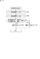
図31は、制御部90が実行する給電制御(給電時不良判定制御を含む)の処理内容を示すフローチャートである。以下、図31を参照しつつ、給電制御の処理手順について説明する。制御部90は、まず、メインスイッチ34が「OFF」の状態から「積込」又は「排出」に切り替え操作されたときの操作信号が入力されるのを待つ(ステップST101)。制御部90は、前記操作信号が入力されると(ステップST101でYesの場合)、給電時不良判定制御の第1給電時不良判定を行う(ステップST102)。
[Power supply control (defective judgment control during power supply)]
FIG. 31 is a flowchart showing the processing contents of the power supply control (including the power supply failure determination control) executed by the
図32は、制御部90が実行する第1給電時不良判定(判定b1)の処理内容を示すフローチャートである。第1給電時不良判定を行う前の状態では、図8に示すように、作業用リレー回路70の接続用リレー71〜75は全て開いており、検知回路80の検知用リレー82,86も全て開いている。
FIG. 32 is a flowchart showing the processing contents of the first power supply failure determination (determination b1) executed by the
第1給電時不良判定において、本実施形態の制御部90は、第1〜第3接続用リレー71〜73及び第5接続用リレー75のそれぞれを第1の判定対象のリレーとして、当該リレーが閉じた状態で固着した場合に起因する動作不良を判定するとともに、第4接続用リレー73、第1検知用リレー82及び第2検知用リレー86のそれぞれを第2の判定対象のリレーとして、当該リレーが開いた状態で固着した場合に起因する動作不良を判定する。
In the first power supply failure determination, the
具体的には、図32において、制御部90は、図8に示す状態から、第1検知用リレー82及び第2検知用リレー86をこの順に閉じた後(ステップST121,ST122)、第4接続用リレー74を閉じる(ステップST123)。これにより、電気回路は、上述の第2初期不良判定を実行したときと同じ図12に示す状態となる。
Specifically, in FIG. 32, the
図12及び図32において、次に、制御部90は、第1及び第2通電検知部81,85がいずれも通電を検知したか否かを判定する(ステップST124)。そして、制御部90は、判定結果が肯定的である場合には、前記第1及び第2の判定対象のリレーに動作不良は発生していないと判定し(ステップST125)、判定結果が否定的である場合には、前記第1又は第2の判定対象のリレーに動作不良が発生していると判定する(ステップST126)。
In FIGS. 12 and 32, the
ここで、第1給電時不良判定の判定結果が否定的となる原因としては、上述の第2初期不良判定の判定結果が否定的となる原因と同様に、上記原因a21〜a27のいずれかであると考えられる。したがって、作業者は、例えば制御部のメモリ等に記憶された給電時不良判定制御の履歴情報から、第1給電時不良判定により給電時不良判定制御が終了したことを確認することで、第1〜第5接続用リレー71〜75、第1検知用リレー82、及び第2検知用リレー86のいずれかの固着に起因した動作不良である可能性が高いと判断することができる。
Here, the cause of the negative determination result of the first power supply failure determination is any of the above causes a21 to a27, as in the case of the above-mentioned cause of the negative determination result of the second initial failure determination. It is believed that there is. Therefore, the operator first confirms that the power supply failure determination control has been completed by the first power supply failure determination from the history information of the power supply failure determination control stored in the memory of the control unit or the like. It can be determined that there is a high possibility of malfunction due to sticking of any of the fifth connection relays 71 to 75, the
なお、第1給電時不良判定では、少なくとも、第1接続用リレー71、第3接続用リレー73及び第5接続用リレー75のそれぞれが閉じた状態で固着した場合に起因する動作不良、並びに、第1検知用リレー82及び第2検知用リレー86のそれぞれが開いた状態で固着した場合に起因する動作不良を判定すればよい。その理由は、以下の通りである。
In the first power supply failure determination, at least the operation failure caused when the
すなわち、第1接続用リレー71又は第5接続用リレー75が閉じた状態で固着すると、ヒューズ76が切れて、バッテリ4とコンデンサ24aとの間の接続電路L10が遮断する恐れがあるためである。また、第3接続用リレー73が閉じた状態で固着すると、接続電路L10に大電流が流れて、短絡気味にコンデンサ24aが充電されてしまい、コンデンサ24aが破損する恐れがあるためである。さらに、第1検知用リレー82又は第2検知用リレー86が開いた状態で固着すると、そもそも第1通電検知部81又は第2通電検知部85で各リレーの動作不良を判定することができなくなるためである。
That is, if the
図31に戻り、制御部90は、第1給電時不良判定が終了すると(ステップST102)、その判定において前記判定対象のリレーに動作不良が発生しているという判定結果となったか否かを確認する(ステップST103)。
ステップST103の確認結果が肯定的である場合、制御部90は給電時不良判定制御の処理を終了する。一方、ステップST103の確認結果が否定的である場合、制御部90は、給電時不良判定制御の第2給電時不良判定を行う(ステップST104)。
Returning to FIG. 31, when the first power supply failure determination is completed (step ST102), the
If the confirmation result in step ST103 is affirmative, the
図33は、制御部90が実行する第2給電時不良判定(判定b2)の処理内容を示すフローチャートである。第2給電時不良判定において、制御部90は、第2接続用リレー72を判定対象のリレーとして、当該リレーが開いた状態で固着した場合に起因する動作不良を判定する。この判定を行う理由は以下の通りである。すなわち、第2接続用リレー72が開いた状態で固着すると、コンデンサ24aが制限抵抗77を介して充電されないため、その後に第2接続用リレー72を閉じたときに、短絡気味にコンデンサ24aが充電されてしまい、コンデンサ24aが破損する恐れがあるためである。
FIG. 33 is a flowchart showing the processing contents of the second power supply failure determination (determination b2) executed by the
図33に示す第2給電時不良判定において、制御部90は、図12に示す状態から、第2接続用リレー72を閉じた後(ステップST131)、第1検知用リレー82を開ける(ステップST132)。これにより、電気回路は、上述の第3初期不良判定を実行したときと同じ図18に示す状態となる。
In the second power supply failure determination shown in FIG. 33, the
図18及び図33において、次に、制御部90は、第1通電検知部81が非通電を検知し、且つ第2通電検知部85が通電を検知したか否かを判定する(ステップST133)。そして、制御部90は、判定結果が肯定的である場合には、前記判定対象のリレーに動作不良は発生していないと判定し(ステップST134)、判定結果が否定的である場合には、前記判定対象のリレーに動作不良が発生していると判定する(ステップST135)。
In FIGS. 18 and 33, next, the
ここで、第2給電時不良判定の判定結果が否定的となる原因としては、図18において、第2接続用リレー72が開いた状態で固着し、図中の太線で示す電力経路が形成されないことで、第1及び第2通電検知部81,85がいずれも非通電を検知している場合が考えられる。したがって、作業者は、例えば制御部のメモリ等に記憶された給電時不良判定制御の履歴情報から、第2給電時不良判定により給電時不良判定制御が終了したことを確認することで、第2接続用リレー72の固着に起因した動作不良である可能性が高いと判断することができる。
Here, the reason why the determination result of the second power supply failure determination is negative is that in FIG. 18, the
なお、本実施形態の給電時不良判定制御では、第4接続用リレー74、第1検知用リレー82及び第2検知用リレー86のそれぞれが閉じた状態で固着した場合に起因する動作不良、並びに、第1接続用リレー71、第3接続用リレー73及び第5接続用リレー75のそれぞれが開いた状態で固着した場合に起因する動作不良は判定しない。その理由は以下の通りである。
In the power supply failure determination control of the present embodiment, malfunctions caused when the
すなわち、第4接続用リレー74が閉じた状態で固着した場合、第4接続用リレー74は低電圧側に設けられており、このような状態でも、第1〜第3接続用リレー71〜73を開閉して電動モータ23に電力供給することで、作業機器を駆動させることができるためである。また、第1検知用リレー82又は第2検知用リレー86が閉じた状態で固着した場合は、電動モータ23に電力供給して作業機器を駆動させているときに、第1通電検知部81又は第2通電検知部85にも電流が流れるが、その電流は第1直列抵抗83又は第2直列抵抗87によって小さくなり、安全上の問題は生じないためである。
That is, when the
また、第5接続用リレー75が開いた状態で固着した場合は、このような状態であっても、第1〜第3接続用リレー71〜73を開閉して電動モータ23に電力供給することで、作業機器を駆動させることができるためである。さらに、第1接続用リレー71及び第3接続用リレー73のいずれかが開いた状態で固着した場合は、電動モータ23への電力供給が不可能となって、単に作業機器を駆動させることができないだけで、安全上の問題は生じないためである。
Further, when the
図31に戻り、制御部90は、第2給電時不良判定が終了すると(ステップST104)、その判定において前記判定対象のリレーに動作不良が発生しているという判定結果となったか否かを確認する(ステップST105)。このステップST105の確認結果が肯定的である場合、制御部90は給電時不良判定制御の処理を終了する。
Returning to FIG. 31, when the second power supply failure determination is completed (step ST104), the
一方、ステップST105の確認結果が否定的である場合、つまり第1及び第2給電時不良判定の判定結果が全て否定的であり、判定対象の接続用リレー71〜75及び検知用リレー82,86のいずれにも動作不良が発生していない場合には、第2給電時不良判定を終了した状態から、バッテリ4からインバータ24に電力供給するために、第1給電時リレー開閉(工程b3)を実行する。
On the other hand, when the confirmation result in step ST105 is negative, that is, the determination results of the first and second power supply failure determinations are all negative, the connection relays 71 to 75 and the detection relays 82 and 86 to be determined are negative. If no malfunction has occurred in any of the above, the first power supply relay opening / closing (step b3) is performed in order to supply power from the
具体的には、制御部90は、第2給電時不良判定を終了した状態(図18参照)から、第1接続用リレー71を閉じた後(ステップST106)、第2検知用リレー86を開ける(ステップST107)。これにより、図34の太線で示す電力経路が形成され、バッテリ4から制限抵抗77を介してインバータ24に電力が供給され、コンデンサ24aの充電が開始される。
Specifically, the
図31及び図34において、次に、制御部90は、第2給電時リレー開閉(工程b4)を実行する。具体的には、制御部90は、第2検知用リレー86を開けた時点から所定時間(コンデンサ24aの充電が完了するまでに必要な時間)が経過した後(ステップST108)、第3接続用リレー73を閉じてから、第2接続用リレー72を開ける。これにより、図35の太線で示す電力経路が形成され、バッテリ4からインバータ24を介して電動モータ23に電力が供給される。
In FIGS. 31 and 34, the
以上のように、制御部90により第1及び第2給電時不良判定を行うことで、検知回路80の第1及び第2通電検知部81,85の検知結果に基づいて、作業用リレー回路70の所定数(5個)の接続用リレー(第1〜第5接続用リレー71〜75)の各動作不良を判定することができる。その際、検知回路80の通電検知部の個数(2個)は、判定対象となる接続用リレーの個数(5個)よりも少ないため、接続用リレーの動作不良を点検するテスターを、判定対象となる所定数の接続用リレーの個数と同数個(5個)設ける場合に比べて、安価な構成で複数の接続用リレーの動作不良を点検することができる。また、第1給電時不良判定を行うことで、第1及び第2検知用リレー82,86の各動作不良も判定することができる。
As described above, the
さらに、給電操作スイッチ(メインスイッチ34)が操作されると、制御部90が給電時不良判定制御を行った後に、所定の接続用リレー71〜73及び検知用リレー86を開閉することで、電動モータ23に電力が供給される。したがって、給電操作スイッチが操作されると、電動モータ23に電力供給するための各接続用リレーの開閉動作を行いながら、給電時不良判定制御が行われるので、複数の接続用リレーの動作不良を簡単かつ迅速に点検することができる。
Further, when the power supply operation switch (main switch 34) is operated, the
[遮断制御(遮断時不良判定制御)]
図36は、制御部90が実行する遮断制御(遮断時不良判定制御を含む)の処理内容を示すフローチャートである。以下、図36を参照しつつ、遮断制御の処理手順について説明する。制御部90は、まず、メインスイッチ34が「積込」又は「排出」の状態から「OFF」に切り替え操作されたときの操作信号が入力されるのを待つ(ステップST201)。制御部90は、前記操作信号が入力されると(ステップST201でYesの場合)、遮断時不良判定制御の第1遮断時不良判定を行う(ステップST202)。
[Blocking control (defective judgment control at blocking)]
FIG. 36 is a flowchart showing the processing contents of the cutoff control (including the cutoff failure determination control) executed by the
図37は、制御部90が実行する第1遮断時不良判定(判定c1)の処理内容を示すフローチャートである。第1遮断時不良判定を行う前の状態では、図35に示すように、作業用リレー回路70の接続用リレー71,73,74は全て閉じており、接続用リレー72,75は全て開いている。また、検知回路80の検知用リレー82,86は全て開いている。
FIG. 37 is a flowchart showing the processing contents of the first failure determination (determination c1) at the time of interruption executed by the
第1遮断時不良判定において、本実施形態の制御部90は、第1接続用リレー71を第1の判定対象のリレーとして、当該リレーが閉じた状態で固着した場合に起因する動作不良を判定するとともに、第1検知用リレー82及び第2検知用リレー86を第2の判定対象のリレーとして、当該リレーが開いた状態で固着した場合に起因する動作不良を判定する。
In the first interruption failure determination, the
前記動作不良c101及び動作不良c102の判定を行う理由は以下の通りである。
すなわち、第1接続用リレー71が閉じた状態で固着すると、電圧値が400Vのバッテリ4に接続される接続電路L10が短絡して危険となるためである。また、第1検知用リレー82又は第2検知用リレー82が開いた状態で固着すると、そもそも第1通電検知部81又は第2通電検知部85で各リレーの動作不良を判定することができなくなるためである。
The reason for determining the malfunction c101 and the malfunction c102 is as follows.
That is, if the
図37に示す第1遮断時不良判定において、制御部90は、図35に示す状態から、第1検知用リレー82及び第2検知用リレー86をこの順に閉じた後(ステップST221,ST222)、第1接続用リレー71及び第3接続用リレー73をこの順に開けて(ステップST223,ST224)、図38に示す状態とする。
In the first interruption failure determination shown in FIG. 37, the
図37及び図38において、次に、制御部90は、第1及び第2通電検知部81,85がいずれも通電を検知したか否かを判定する(ステップST225)。そして、制御部90は、判定結果が肯定的である場合には、前記第1及び第2の判定対象のリレーに動作不良は発生していないと判定し(ステップST226)、判定結果が否定的である場合には、前記第1又は第2の判定対象のリレーに動作不良が発生していると判定する(ステップST227)。
In FIGS. 37 and 38, the
ここで、第1遮断時不良判定の判定結果が否定的となる原因としては、下記の原因c11〜c13のいずれかであると考えられる。
原因c11:図39に示すように、第1接続用リレー71が閉じた状態で固着し、図中の太線で示す電力経路が形成されることで、第1通電検知部81が通電を検知し、且つ第2通電検知部85が非通電を検知した状態となる。
原因c12:図38において、第1検知用リレー82が開いた状態で固着し、図中の太線で示す電力経路が形成されないことで、第1及び第2通電検知部81,85がいずれも非通電を検知した状態となる。
原因c13:図38において、第2検知用リレー86が開いた状態で固着し、図中の太線で示す電力経路が形成されないことで、第1及び第2通電検知部81,85がいずれも非通電を検知した状態となる。
Here, it is considered that one of the following causes c11 to c13 is the cause of the negative determination result of the first blocking failure determination.
Cause c11: As shown in FIG. 39, the
Cause c12: In FIG. 38, the
Cause c13: In FIG. 38, the
したがって、作業者は、例えば制御部のメモリ等に記憶された遮断時不良判定制御の履歴情報から、第1遮断時不良判定により遮断時不良判定制御が終了したことを確認することで、第1接続用リレー71、第1検知用リレー82、及び第2検知用リレー86のいずれかの固着に起因した動作不良である可能性が高いと判断することができる。
Therefore, the operator first confirms that the interruption failure determination control has been completed by the first interruption failure determination from the history information of the interruption failure determination control stored in the memory of the control unit or the like. It can be determined that there is a high possibility of malfunction due to sticking of any of the
図36に戻り、制御部90は、第1遮断時不良判定が終了すると(ステップST202)、その判定において前記判定対象のリレーに動作不良が発生しているという判定結果となったか否かを確認する(ステップST203)。
ステップST203の確認結果が肯定的である場合、制御部90は遮断時不良判定制御の処理を終了する。一方、ステップST203の確認結果が否定的である場合、制御部90は、遮断時不良判定制御の第2遮断時不良判定を行う(ステップST204)。
Returning to FIG. 36, when the first shutoff failure determination is completed (step ST202), the
If the confirmation result in step ST203 is affirmative, the
図40は、制御部90が実行する第2遮断時不良判定(判定c2)の処理内容を示すフローチャートである。第2遮断時不良判定において、本実施形態の制御部90は、第2接続用リレー72、第3接続用リレー73、及び第2検知用リレー86のそれぞれを判定対象のリレーとして、当該リレーが閉じた状態で固着した場合に起因する動作不良を判定する。具体的には、図40において、制御部90は、図38に示す状態から、第2検知用リレー86を開けて(ステップST231)、図41に示す状態とする。
FIG. 40 is a flowchart showing the processing contents of the second shutoff failure determination (determination c2) executed by the
図40及び図41において、次に、制御部90は、第1及び第2通電検知部81,85がいずれも非通電を検知したか否かを判定する(ステップST232)。そして、制御部90は、判定結果が肯定的である場合には、前記判定対象のリレーに動作不良は発生していないと判定し(ステップST233)、判定結果が否定的である場合には、前記判定対象のリレーに動作不良が発生していると判定する(ステップST234)。
In FIGS. 40 and 41, the
ここで、第2遮断時不良判定の判定結果が否定的となる原因としては、下記の原因c21〜c23のいずれかであると考えられる。
原因c21:図42に示すように、第3接続用リレー73が閉じた状態で固着し、図中の太線で示す電力経路が形成されることで、第1通電検知部81が通電を検知し、且つ第2通電検知部85が非通電を検知した状態となる。
原因c22:図43に示すように、第2接続用リレー72が閉じた状態で固着し、図中の太線で示す電力経路が形成されることで、第1通電検知部81が通電を検知し、且つ第2通電検知部85が非通電を検知した状態となる。
原因c23:図44に示すように、第2検知用リレー86が閉じた状態で固着し、図中の太線で示す電力経路が形成されることで、第1及び第2通電検知部81,85がいずれも通電を検知した状態となる。
Here, it is considered that one of the following causes c21 to c23 is the cause of the negative determination result of the second interruption failure determination.
Cause c21: As shown in FIG. 42, the
Cause c22: As shown in FIG. 43, the
Cause c23: As shown in FIG. 44, the
したがって、作業者は、例えば制御部のメモリ等に記憶された遮断時不良判定制御の履歴情報から、第2遮断時不良判定により遮断時不良判定制御が終了したことを確認することで、第2接続用リレー72、第3接続用リレー73、及び第2検知用リレー86のいずれかの固着に起因した動作不良である可能性が高いと判断することができる。
Therefore, the operator confirms that the interruption failure determination control has been completed by the second interruption failure determination from the history information of the interruption failure determination control stored in, for example, the memory of the control unit. It can be determined that there is a high possibility of malfunction due to sticking of any of the
なお、第2遮断時不良判定では、少なくとも、第3接続用リレー73が閉じた状態で固着した場合に起因する動作不良を判定すればよい。この動作不良の判定を必須としている理由は、以下の通りである。すなわち、第3接続用リレー73が閉じた状態で固着すると、コンデンサ24aに充電された電力を制限抵抗77によって安全に放電させることができなくなるためである。
In the second cutoff failure determination, at least, the operation failure caused when the
また、本実施形態の遮断時不良判定制御では、第4接続用リレー74、第5接続用リレー75及び第1検知用リレー82のそれぞれが閉じた状態で固着した場合に起因する動作不良、並びに、第1接続用リレー71、第3接続用リレー73及び第4接続用リレー74のそれぞれが開いた状態で固着した場合に起因する動作不良は判定しない。その理由は以下の通りである。
Further, in the failure determination control at the time of interruption of the present embodiment, malfunctions caused when the
すなわち、第4接続用リレー74が閉じた状態で固着した場合、第4接続用リレー74は低電圧側であり、このような状態でも、第1〜第3接続用リレー71〜73を開閉して電動モータ23に電力供給することで、作業機器を駆動させることができるためである。また、第5接続用リレー75が閉じた状態で固着した場合は、第1給電時不良判定で既に判定しているためである。また、第1検知用リレー82が閉じた状態で固着した場合は、電動モータ23に電力供給して作業機器を駆動させているときに、第1通電検知部81にも電流が流れるが、その電流は第1直列抵抗83によって小さくなり、安全上の問題は生じないためである。
That is, when the
また、第1接続用リレー71及び第3接続用リレー73のいずれかが開いた状態で固着した場合は、電動モータ23への電力供給が不可能となって、単に作業機器を駆動させることができないだけで、安全上の問題は生じないためである。さらに、第4接続用リレー75が開いた状態で固着した場合は、第1給電時不良判定で既に判定しているためである。
Further, if either the
図36に戻り、制御部90は、第2遮断時不良判定が終了すると(ステップST204)、その判定において前記判定対象のリレーに動作不良が発生しているという判定結果となったか否かを確認する(ステップST205)。このステップST205の確認結果が肯定的である場合、制御部90は遮断時不良判定制御の処理を終了する。
Returning to FIG. 36, when the second shutoff failure determination is completed (step ST204), the
一方、ステップST205の確認結果が否定的である場合、つまり第1及び第2遮断時不良判定の判定結果が全て否定的であり、判定対象の接続用リレー71〜73及び検知用リレー82,86のいずれにも動作不良が発生していない場合には、第2遮断時不良判定を終了した状態から、コンデンサ24aを放電するために、第1遮断時リレー開閉(工程c3)を実行する。
On the other hand, when the confirmation result in step ST205 is negative, that is, the judgment results of the first and second interruption failure judgments are all negative, and the connection relays 71 to 73 and the detection relays 82 and 86 to be judged are negative. If no malfunction has occurred in any of the above, the relay opening / closing (step c3) at the time of the first interruption is executed in order to discharge the
具体的には、制御部90は、第2遮断時不良判定が終了した状態(図41参照)から、第5接続用リレー75及び第2接続用リレー72をこの順に閉じた後(ステップST206,ST207)、第4接続用リレー74を開ける(ステップST208)。これにより、図45の太線で示す電力経路が形成され、コンデンサ24aの放電が開始される。
Specifically, the
図36及び図45において、次に、制御部90は、第2遮断時リレー開閉(工程c4)を実行する。具体的には、制御部90は、第4接続用リレー74を開けた時点から所定時間(コンデンサ24aの放電が完了するまでに必要な時間)が経過した後(ステップST209)、第2接続用リレー72、第5接続用リレー75、及び第1検知用リレー82をこの順に開ける(ステップST210,ST211,ST212)。これにより、図8に示す状態に戻り、バッテリ4から電動モータ23への電力供給は遮断される。
In FIGS. 36 and 45, the
以上のように、制御部90により第1及び第2遮断時不良判定を行うことで、検知回路80の第1及び第2通電検知部81,85の検知結果に基づいて、作業用リレー回路70の所定数(3個)の接続用リレー(第1〜第3接続用リレー71〜73)の各動作不良を判定することができる。その際、検知回路80の通電検知部の個数(2個)は、判定対象となる接続用リレーの個数(3個)よりも少ないため、接続用リレーの動作不良を点検するテスターを、判定対象となる所定数の接続用リレーの個数と同数個(3個)設ける場合に比べて、安価な構成で複数の接続用リレーの動作不良を点検することができる。また、第1及び第2遮断時不良判定を行うことで、第1及び第2検知用リレー82,86の各動作不良も判定することができる。
As described above, the
さらに、遮断操作スイッチ(メインスイッチ34)が操作されると、制御部90が遮断時不良判定制御を行った後に、所定の接続用リレー72,74,75及び検知用リレー82を開閉制御することで、電動モータ23への電力供給が遮断される。したがって、遮断操作スイッチが操作されると、電動モータ23への電力供給を遮断するための各接続用リレーの開閉動作を行いながら、遮断時不良判定制御が行われるので、複数の接続用リレーの動作不良を簡単かつ迅速に点検することができる。
Further, when the cutoff operation switch (main switch 34) is operated, the
なお、今回開示された実施形態はすべての点で例示であって制限的なものではないと考えられるべきである。本発明の範囲は、上記した意味ではなく、特許請求の範囲によって示され、特許請求の範囲と均等の意味、及び範囲内でのすべての変更が含まれることが意図される。 It should be noted that the embodiments disclosed this time are exemplary in all respects and are not restrictive. The scope of the present invention is indicated by the scope of claims, not the above-mentioned meaning, and is intended to include the meaning equivalent to the scope of claims and all modifications within the scope.
例えば、本実施形態では、初期不良判定制御、給電時不良判定制御、及び遮断時不良判定制御は、全て同じ制御部90によって実行されるが、これらの制御が互いに異なる制御部によって実行されてもよいし、1つの制御が他の2つの制御と異なる制御部によって実行されていてもよい。また、本実施形態では、初期不良判定制御、給電時不良判定制御、及び遮断時不良判定制御が行われるが、いずれか1つの制御だけが行われるものであってもよい。
For example, in the present embodiment, the initial failure determination control, the power supply failure determination control, and the interruption failure determination control are all executed by the
また、積込装置Tは、押込板108と回転板115との協働により塵芥を積み込む回転板式であるが、押込板のみで塵芥を積み込むプレス式であってもよい。また、本実施形態の塵芥収集車1は、塵芥収容箱2をダンプさせることにより塵芥を外部へ排出しているが、塵芥収容箱内において前後移動可能に設けられた排出板により塵芥を外部へ排出するものであってもよい。
Further, the loading device T is a rotary plate type for loading dust by the cooperation of the
また、本実施形態では、1つのバッテリ4に、2つの負荷(車両走行用駆動部D1及び作業用駆動部D2)が接続されているが、3つ以上の負荷(例えば、車両走行用駆動部D1、及び2つ以上のインバータ付き電動モータからなる作業用駆動部)が接続されていてもよいし、1つの負荷(例えば作業機器専用のバッテリ)が接続されていてもよい。
Further, in the present embodiment, two loads (vehicle driving unit D1 and work driving unit D2) are connected to one
また、本実施形態の作業用駆動部D2は、油圧ポンプ22及び油圧アクチュエータ(スイングシリンダ20、押込シリンダ112、油圧モータ117、ダンプシリンダ119)を介して塵芥収集機器を駆動しているが、電動アクチュエータにより塵芥収集機器を直接駆動してもよい。また、本発明は、塵芥収集車以外に、他の作業機器を搭載した作業車両にも適用することができる。
Further, the work drive unit D2 of the present embodiment drives a dust collecting device via a
1 塵芥収集車(作業車両)
4 バッテリ
10 車体
23 電動モータ(駆動本体部)
24a コンデンサ(充電部)
34 メインスイッチ(給電操作スイッチ,遮断操作スイッチ)
70 作業用リレー回路(リレー回路)
71 第1接続用リレー(接続用リレー)
72 第2接続用リレー(接続用リレー)
73 第3接続用リレー(接続用リレー)
74 第4接続用リレー(接続用リレー)
75 第5接続用リレー(接続用リレー)
80 検知回路
81 第1通電検知部(通電検知部)
82 第1検知用リレー
85 第2通電検知部(通電検知部)
86 第2検知用リレー
90 制御部
D1 車両走行用駆動部
D2 作業用駆動部
L5 第1検知用電路
L6 第2検知用電路
L10 接続電路
L20 検知用電路
Lb10 バイパス電路
Lp10 プラス側接続電路
Ln10 マイナス側接続電路
P1 プラス側バイパス接続点
P2 マイナス側バイパス接続点
P4 第1プラス側接続点
P5 マイナス側接続点
P6 第2プラス側接続点
P7 第3プラス側接続点
1 Garbage truck (working vehicle)
4
24a capacitor (charging unit)
34 Main switch (power supply operation switch, cutoff operation switch)
70 Work relay circuit (relay circuit)
71 1st connection relay (connection relay)
72 Second connection relay (connection relay)
73 Third connection relay (connection relay)
74 4th connection relay (connection relay)
75 Fifth connection relay (connection relay)
80
82
86
Claims (3)
前記バッテリから電力供給を受けて充電する充電部、及び前記充電部から電力供給を受けて車体に架装された作業機器を駆動する駆動本体部を有する作業用駆動部と、
前記バッテリと前記充電部とを接続している接続電路を開閉可能な複数の接続用リレーを有するリレー回路と、
前記接続電路の途中に接続された検知用電路、及び当該検知用電路の通電状態を検知する通電検知部を有する検知回路と、
前記通電検知部の検知結果に基づいて、前記複数の接続用リレーに動作不良が発生しているか否かを判定する制御部と、を備え、
前記接続電路は、
前記バッテリのプラス側と前記充電部のプラス側とを接続しているプラス側接続電路と、
前記バッテリのマイナス側と前記充電部のマイナス側とを接続しているマイナス側接続電路と、
前記プラス側接続電路の途中のプラス側バイパス接続点、及び前記マイナス側接続電路の途中のマイナス側バイパス接続点を接続しているバイパス電路と、を有し、
前記リレー回路は、
前記プラス側接続電路の前記プラス側バイパス接続点よりも前記バッテリ側に設けられた、前記プラス側接続電路を開閉可能な第1接続用リレーと、
前記プラス側接続電路の前記プラス側バイパス接続点と前記充電部のプラス側との間で直列に接続された、前記プラス側接続電路を開閉可能な第2接続用リレー、及び接続用抵抗と、
前記プラス側接続電路の前記プラス側バイパス接続点よりも前記充電部側において、前記第1接続用リレーに対して直列に接続されているとともに、前記第2接続用リレー及び前記接続用抵抗に対して並列に接続された、前記プラス側接続電路を開閉可能な第3接続用リレーと、
前記マイナス側接続電路の前記マイナス側バイパス接続点よりも前記バッテリ側に設けられた、当該マイナス側接続電路を開閉可能な第4接続用リレーと、
前記バイパス電路の途中に設けられた、当該バイパス電路を開閉可能な第5接続用リレーと、を有し、
前記検知回路は、
前記プラス側接続電路における前記第1接続用リレーと前記プラス側バイパス接続点との間の第1プラス側接続点、及び前記マイナス側接続電路における前記第4接続用リレーと前記マイナス側バイパス接続点との間のマイナス側接続点を接続している第1検知用電路と、
前記第1検知用電路の途中である第2プラス側接続点、及び前記プラス側接続電路における前記第1接続用リレーよりも前記バッテリ側の第3プラス側接続点を接続している第2検知用電路と、
前記第1検知用電路の前記第2プラス側接続点と前記マイナス側接続点との間において直列に接続された、前記第1検知用電路を開閉可能な第1検知用リレー、及び前記第1検知用電路の通電状態を検知する第1通電検知部と、
前記第2検知用電路の前記第2プラス側接続点と前記第3プラス側接続点との間において直列に接続された、前記第2検知用電路の通電状態を検知する第2通電検知部、及び前記第2検知用電路を開閉可能な第2検知用リレーと、を有し、
前記制御部は、前記第1〜第5接続用リレー及び前記第1〜第2検知用リレーが全て開いている状態から、次の工程a1〜a8をこの順に実行する制御を行い、これらの工程a1〜a8のそれぞれにおいて判定対象のリレーに動作不良が発生していると判定した場合には、次工程があっても前記制御を終了する、作業車両。
工程a1:前記第4接続用リレーを判定対象のリレーとして当該リレーの動作不良を判定する工程であって、前記第1検知用リレー及び前記第2検知用リレーをこの順に閉じたときに、前記第1通電検知部及び前記第2通電検知部がいずれも非通電を検知した場合は、前記判定対象のリレーに動作不良は発生していないと判定し、それ以外の場合は、前記判定対象のリレーに動作不良が発生していると判定する工程
工程a2:前記第1〜第5接続用リレー、前記第1検知用リレー、及び前記第2検知用リレーを判定対象のリレーとして当該リレーの動作不良を判定する工程であって、前記第4接続用リレーを閉じたときに、前記第1通電検知部及び前記第2通電検知部がいずれも通電を検知した場合は、前記判定対象のリレーに動作不良は発生していないと判定し、それ以外の場合は、前記判定対象のリレーに動作不良が発生していると判定する工程
工程a3:前記第2接続用リレーを判定対象のリレーとして当該リレーの動作不良を判定する工程であって、前記第2接続用リレーを閉じた後に、前記第1検知用リレーを開けたときに、前記第1通電検知部が非通電を検知し且つ前記第2通電検知部が通電を検知したか否かを判定する工程
工程a4:前記第3接続用リレーを判定対象のリレーとして当該リレーの動作不良を判定する工程であって、前記第3接続用リレーを閉じた後に、前記第2接続用リレーを開けたときに、前記第1通電検知部が非通電を検知し且つ前記第2通電検知部が通電を検知した場合は、前記判定対象のリレーに動作不良は発生していないと判定し、それ以外の場合は、前記判定対象のリレーに動作不良が発生していると判定する工程
工程a5:前記第5接続用リレーを判定対象のリレーとして当該リレーの動作不良を判定する工程であって、前記第5接続用リレーを閉じた後に、前記第3接続用リレーを開けたときに、前記第1通電検知部が非通電を検知し且つ前記第2通電検知部が通電を検知した場合は、前記判定対象のリレーに動作不良は発生していないと判定し、それ以外の場合は、前記判定対象のリレーに動作不良が発生していると判定する工程
工程a6:前記第1検知用リレーを判定対象のリレーとして当該リレーの動作不良を判定する工程であって、前記第5接続用リレーを開けたときに、前記第1通電検知部及び前記第2通電検知部がいずれも非通電を検知した場合は、前記判定対象のリレーに動作不良は発生していないと判定し、それ以外の場合は、前記判定対象のリレーに動作不良が発生していると判定する工程
工程a7:前記第2検知用リレーを判定対象のリレーとして当該リレーの動作不良を判定する工程であって、前記第1検知用リレーを閉じた後に、前記第2検知用リレーを開けたときに、前記第1通電検知部及び前記第2通電検知部がいずれも非通電を検知した場合は、前記判定対象のリレーに動作不良は発生していないと判定し、それ以外の場合は、前記判定対象のリレーに動作不良が発生していると判定する工程
工程a8:前記第1接続用リレーを判定対象のリレーとして当該リレーの動作不良を判定する工程であって、前記第1接続用リレーを閉じたときに、前記第1通電検知部が通電を検知し且つ前記第2通電検知部が非通電を検知した場合は、前記判定対象のリレーに動作不良は発生していないと判定し、それ以外の場合は、前記判定対象のリレーに動作不良が発生していると判定する工程 With the battery
A charging unit that receives power from the battery to charge the battery, and a working drive unit that has a drive main body that receives power from the charging unit to drive the work equipment mounted on the vehicle body.
A relay circuit having a plurality of connection relays capable of opening and closing the connection electric circuit connecting the battery and the charging unit, and
A detection circuit connected in the middle of the connection electric circuit, a detection circuit having an energization detection unit for detecting the energization state of the detection electric circuit, and a detection circuit.
A control unit for determining whether or not a malfunction has occurred in the plurality of connection relays based on the detection result of the energization detection unit is provided.
The connecting electric circuit is
A positive connection electric circuit connecting the positive side of the battery and the positive side of the charging unit, and
A negative side connection circuit connecting the negative side of the battery and the negative side of the charging unit, and
It has a plus-side bypass connection point in the middle of the plus-side connection line and a bypass line connecting the minus-side bypass connection point in the middle of the minus-side connection line.
The relay circuit
A first connection relay that can open and close the positive side connection circuit, which is provided on the battery side of the positive side bypass connection point of the positive side connection circuit.
A second connection relay that can open and close the positive connection circuit, which is connected in series between the positive bypass connection point of the positive connection circuit and the positive side of the charging unit, and a connection resistor.
On the charging part side of the positive side bypass connection point of the positive side connection circuit, the relay is connected in series to the first connection relay, and the second connection relay and the connection resistor are connected to each other. A third connection relay that can open and close the positive side connection circuit, which is connected in parallel.
A fourth connection relay that can open and close the negative side connection circuit, which is provided on the battery side of the negative side bypass connection point of the negative side connection circuit.
It has a fifth connection relay that can open and close the bypass electric circuit, which is provided in the middle of the bypass electric circuit.
The detection circuit
The first positive side connection point between the first connection relay and the positive side bypass connection point in the positive side connection circuit, and the fourth connection relay and the negative side bypass connection point in the negative side connection circuit. The first detection electric circuit connecting the minus side connection point between and
The second detection that connects the second positive side connection point in the middle of the first detection electric circuit and the third positive side connection point on the battery side of the first connection relay in the positive side connection electric circuit. Electric circuit and
A first detection relay capable of opening and closing the first detection electric circuit connected in series between the second positive side connection point and the negative side connection point of the first detection electric circuit, and the first detection electric circuit. The first energization detection unit that detects the energization state of the detection electric circuit, and
A second energization detection unit that detects an energized state of the second detection electric circuit, which is connected in series between the second positive side connection point and the third positive side connection point of the second detection electric circuit. And a second detection relay that can open and close the second detection electric circuit.
The control unit controls to execute the next steps a1 to a8 in this order from the state in which the first to fifth connection relays and the first to second detection relays are all open, and these steps A work vehicle that terminates the control even if there is a next step when it is determined that a malfunction has occurred in the relay to be determined in each of a1 to a8.
Step a1: In the step of determining the malfunction of the relay by using the fourth connection relay as the relay to be determined, when the first detection relay and the second detection relay are closed in this order, the above. When both the first energization detection unit and the second energization detection unit detect non-energization, it is determined that no malfunction has occurred in the relay to be determined, and in other cases, the determination target is determined. Step a2 of determining that a malfunction has occurred in the relay: Operation of the relay with the first to fifth connection relays, the first detection relay, and the second detection relay as the relays to be determined. In the step of determining a defect, when the first energization detection unit and the second energization detection unit both detect energization when the fourth connection relay is closed, the relay to be determined is selected. A step of determining that no malfunction has occurred, and otherwise determining that a malfunction has occurred in the relay to be determined. Step a3: The second connection relay is used as the relay to be determined. In the step of determining the malfunction of the relay, when the first detection relay is opened after the second connection relay is closed, the first energization detection unit detects non-energization and the first 2 Step of determining whether or not the energization detection unit has detected energization Step a4: A step of determining the malfunction of the relay by using the third connection relay as a relay to be determined, and the third connection relay. When the second connection relay is opened after closing, if the first energization detection unit detects non-energization and the second energization detection unit detects energization, the relay to be determined is selected. A step of determining that no malfunction has occurred, and otherwise determining that a malfunction has occurred in the relay to be determined. Step a5: The fifth connection relay is used as the relay to be determined. In the step of determining the malfunction of the relay, when the third connection relay is opened after the fifth connection relay is closed, the first energization detection unit detects non-energization and the first energization is detected. 2 When the energization detection unit detects energization, it is determined that no malfunction has occurred in the relay to be determined, and in other cases, it is determined that the relay to be determined has a malfunction. Step a6: A step of determining the malfunction of the relay by using the first detection relay as a relay to be determined, and when the fifth connection relay is opened, the first energization detection unit and the above. If any of the second energization detectors detects non-energization , It is determined that no malfunction has occurred in the relay to be determined, and in other cases, it is determined that the relay to be determined has malfunction. Step a7: The second detection relay In the step of determining the malfunction of the relay by using the above as the relay to be determined, when the second detection relay is opened after the first detection relay is closed, the first energization detection unit and the said If any of the second energization detection units detects non-energization, it is determined that no malfunction has occurred in the relay to be determined, and in other cases, a malfunction has occurred in the relay to be determined. Step a8: A step of determining the malfunction of the relay by using the first connection relay as a relay to be determined, and when the first connection relay is closed, the first energization is performed. When the detection unit detects energization and the second energization detection unit detects non-energization, it is determined that no malfunction has occurred in the relay to be determined, and in other cases, the determination target is determined. The process of determining that a malfunction has occurred in the relay
前記バッテリから電力供給を受けて充電する充電部、及び前記充電部から電力供給を受けて車体に架装された作業機器を駆動する駆動本体部を有する作業用駆動部と、
前記駆動本体部に電力を供給する操作信号を出力する給電操作スイッチと、
前記バッテリと前記充電部とを接続している接続電路を開閉可能な複数の接続用リレーを有するリレー回路と、
前記接続電路の途中に接続された検知用電路、及び当該検知用電路の通電状態を検知する通電検知部を有する検知回路と、
前記通電検知部の検知結果に基づいて、所定数の前記接続用リレーに動作不良が発生しているか否かを判定する制御部と、を備え、
前記接続電路は、
前記バッテリのプラス側と前記充電部のプラス側とを接続しているプラス側接続電路と、
前記バッテリのマイナス側と前記充電部のマイナス側とを接続しているマイナス側接続電路と、
前記プラス側接続電路の途中のプラス側バイパス接続点、及び前記マイナス側接続電路の途中のマイナス側バイパス接続点を接続しているバイパス電路と、を有し、
前記リレー回路は、
前記プラス側接続電路の前記プラス側バイパス接続点よりも前記バッテリ側に設けられた、前記プラス側接続電路を開閉可能な第1接続用リレーと、
前記プラス側接続電路の前記プラス側バイパス接続点と前記充電部のプラス側との間で直列に接続された、前記プラス側接続電路を開閉可能な第2接続用リレー、及び接続用抵抗と、
前記プラス側接続電路の前記プラス側バイパス接続点よりも前記充電部側において、前記第1接続用リレーに対して直列に接続されているとともに、前記第2接続用リレー及び前記接続用抵抗に対して並列に接続された、前記プラス側接続電路を開閉可能な第3接続用リレーと、
前記マイナス側接続電路の前記マイナス側バイパス接続点よりも前記バッテリ側に設けられた、当該マイナス側接続電路を開閉可能な第4接続用リレーと、
前記バイパス電路の途中に設けられた、当該バイパス電路を開閉可能な第5接続用リレーと、を有し、
前記検知回路は、
前記プラス側接続電路における前記第1接続用リレーと前記プラス側バイパス接続点との間の第1プラス側接続点、及び前記マイナス側接続電路における前記第4接続用リレーと前記マイナス側バイパス接続点との間のマイナス側接続点を接続している第1検知用電路と、
前記第1検知用電路の途中である第2プラス側接続点、及び前記プラス側接続電路における前記第1接続用リレーよりも前記バッテリ側の第3プラス側接続点を接続している第2検知用電路と、
前記第1検知用電路の前記第2プラス側接続点と前記マイナス側接続点との間において直列に接続された、前記第1検知用電路を開閉可能な第1検知用リレー、及び前記第1検知用電路の通電状態を検知する第1通電検知部と、
前記第2検知用電路の前記第2プラス側接続点と前記第3プラス側接続点との間において直列に接続された、前記第2検知用電路の通電状態を検知する第2通電検知部、及び前記第2検知用電路を開閉可能な第2検知用リレーと、を有し、
前記制御部は、前記給電操作スイッチの操作信号が入力されると、前記第1〜第5接続用リレー及び前記第1〜第2検知用リレーが全て開いている状態から、次の工程b1〜b4をこの順に実行する制御を行い、前記工程b1及びb2のそれぞれにおいて判定対象のリレーに動作不良が発生していると判定した場合には、次工程以降を実行することなく前記制御を終了する、作業車両。
工程b1:少なくとも、前記第1接続用リレー、前記第3接続用リレー、前記第5接続用リレー、前記第1検知用リレー、及び前記第2検知用リレーを判定対象のリレーとして当該リレーの動作不良を判定する工程であって、前記第1検知用リレー、前記第2検知用リレー、及び前記第4接続用リレーをこの順に閉じたときに、前記第1通電検知部及び前記第2通電検知部がいずれも通電を検知した場合は、前記判定対象のリレーに動作不良は発生していないと判定し、それ以外の場合は、前記判定対象のリレーに動作不良が発生していると判定する工程
工程b2:前記第2接続用リレーを判定対象のリレーとして当該リレーの動作不良を判定する工程であって、前記第2接続用リレーを閉じた後に、前記第1検知用リレーを開けたときに、前記第1通電検知部が非通電を検知し且つ前記第2通電検知部が通電を検知した場合は、前記判定対象のリレーに動作不良は発生していないと判定し、それ以外の場合は、前記判定対象のリレーに動作不良が発生していると判定する工程
工程b3:前記第1接続用リレーを閉じた後に、前記第2検知用リレーを開ける工程
工程b4:前記第2検知用リレーを開けた時点から所定時間が経過した後に、前記第3接続用リレーを閉じてから前記第2接続用リレーを開ける工程 With the battery
A charging unit that receives power from the battery to charge the battery, and a working drive unit that has a drive main body that receives power from the charging unit to drive the work equipment mounted on the vehicle body.
A power supply operation switch that outputs an operation signal that supplies power to the drive body,
A relay circuit having a plurality of connection relays capable of opening and closing the connection electric circuit connecting the battery and the charging unit, and
A detection circuit connected in the middle of the connection electric circuit, a detection circuit having an energization detection unit for detecting the energization state of the detection electric circuit, and a detection circuit.
A control unit for determining whether or not a predetermined number of the connection relays have malfunctioned based on the detection result of the energization detection unit is provided.
The connecting electric circuit is
A positive connection electric circuit connecting the positive side of the battery and the positive side of the charging unit, and
A negative side connection circuit connecting the negative side of the battery and the negative side of the charging unit, and
It has a plus-side bypass connection point in the middle of the plus-side connection line and a bypass line connecting the minus-side bypass connection point in the middle of the minus-side connection line.
The relay circuit
A first connection relay that can open and close the positive side connection circuit, which is provided on the battery side of the positive side bypass connection point of the positive side connection circuit.
A second connection relay that can open and close the positive connection circuit, which is connected in series between the positive bypass connection point of the positive connection circuit and the positive side of the charging unit, and a connection resistor.
On the charging part side of the positive side bypass connection point of the positive side connection circuit, the relay is connected in series to the first connection relay, and the second connection relay and the connection resistor are connected to each other. A third connection relay that can open and close the positive side connection circuit, which is connected in parallel.
A fourth connection relay that can open and close the negative side connection circuit, which is provided on the battery side of the negative side bypass connection point of the negative side connection circuit.
It has a fifth connection relay that can open and close the bypass electric circuit, which is provided in the middle of the bypass electric circuit.
The detection circuit
The first positive side connection point between the first connection relay and the positive side bypass connection point in the positive side connection circuit, and the fourth connection relay and the negative side bypass connection point in the negative side connection circuit. The first detection electric circuit connecting the minus side connection point between and
The second detection that connects the second positive side connection point in the middle of the first detection electric circuit and the third positive side connection point on the battery side of the first connection relay in the positive side connection electric circuit. Electric circuit and
A first detection relay capable of opening and closing the first detection electric circuit connected in series between the second positive side connection point and the negative side connection point of the first detection electric circuit, and the first detection electric circuit. The first energization detection unit that detects the energization state of the detection electric circuit, and
A second energization detection unit that detects an energized state of the second detection electric circuit, which is connected in series between the second positive side connection point and the third positive side connection point of the second detection electric circuit. And a second detection relay that can open and close the second detection electric circuit.
When the operation signal of the power supply operation switch is input, the control unit starts from a state in which the first to fifth connection relays and the first to second detection relays are all open, and then steps b1 to the next. Control is performed to execute b4 in this order, and if it is determined in each of the steps b1 and b2 that a malfunction has occurred in the relay to be determined, the control is terminated without executing the next and subsequent steps. , Work vehicle.
Step b1: At least, the operation of the relay with the first connection relay, the third connection relay, the fifth connection relay, the first detection relay, and the second detection relay as the relays to be determined. In the step of determining a defect, when the first detection relay, the second detection relay, and the fourth connection relay are closed in this order, the first energization detection unit and the second energization detection If any of the units detects energization, it is determined that no malfunction has occurred in the relay to be determined, and in other cases, it is determined that the relay to be determined has malfunction. Step Step b2: A step of determining the malfunction of the relay by using the second connection relay as a relay to be determined, and when the first detection relay is opened after the second connection relay is closed. When the first energization detection unit detects non-energization and the second energization detection unit detects energization, it is determined that no malfunction has occurred in the relay to be determined, and in other cases. Is a step of determining that a malfunction has occurred in the relay to be determined. Step b3: A step of opening the second detection relay after closing the first connection relay. Step b4: The second detection. A step of closing the third connection relay and then opening the second connection relay after a predetermined time has elapsed from the time when the relay is opened.
前記バッテリから電力供給を受けて充電する充電部、及び前記充電部から電力供給を受けて車体に架装された作業機器を駆動する駆動本体部を有する作業用駆動部と、
前記駆動本体部への電力供給を遮断する操作信号を出力する遮断操作スイッチと、
前記バッテリと前記充電部とを接続している接続電路を開閉可能な複数の接続用リレーを有するリレー回路と、
前記接続電路の途中に接続された検知用電路、及び当該検知用電路の通電状態を検知する通電検知部を有する検知回路と、
前記通電検知部の検知結果に基づいて、所定数の前記接続用リレーに動作不良が発生しているか否かを判定する制御部と、を備え、
前記接続電路は、
前記バッテリのプラス側と前記充電部のプラス側とを接続しているプラス側接続電路と、
前記バッテリのマイナス側と前記充電部のマイナス側とを接続しているマイナス側接続電路と、
前記プラス側接続電路の途中のプラス側バイパス接続点、及び前記マイナス側接続電路の途中のマイナス側バイパス接続点を接続しているバイパス電路と、を有し、
前記リレー回路は、
前記プラス側接続電路の前記プラス側バイパス接続点よりも前記バッテリ側に設けられた、前記プラス側接続電路を開閉可能な第1接続用リレーと、
前記プラス側接続電路の前記プラス側バイパス接続点と前記充電部のプラス側との間で直列に接続された、前記プラス側接続電路を開閉可能な第2接続用リレー、及び接続用抵抗と、
前記プラス側接続電路の前記プラス側バイパス接続点よりも前記充電部側において、前記第1接続用リレーに対して直列に接続されているとともに、前記第2接続用リレー及び前記接続用抵抗に対して並列に接続された、前記プラス側接続電路を開閉可能な第3接続用リレーと、
前記マイナス側接続電路の前記マイナス側バイパス接続点よりも前記バッテリ側に設けられた、当該マイナス側接続電路を開閉可能な第4接続用リレーと、
前記バイパス電路の途中に設けられた、当該バイパス電路を開閉可能な第5接続用リレーと、を有し、
前記検知回路は、
前記プラス側接続電路における前記第1接続用リレーと前記プラス側バイパス接続点との間の第1プラス側接続点、及び前記マイナス側接続電路における前記第4接続用リレーと前記マイナス側バイパス接続点との間のマイナス側接続点を接続している第1検知用電路と、
前記第1検知用電路の途中である第2プラス側接続点、及び前記プラス側接続電路における前記第1接続用リレーよりも前記バッテリ側の第3プラス側接続点を接続している第2検知用電路と、
前記第1検知用電路の前記第2プラス側接続点と前記マイナス側接続点との間において直列に接続された、前記第1検知用電路を開閉可能な第1検知用リレー、及び前記第1検知用電路の通電状態を検知する第1通電検知部と、
前記第2検知用電路の前記第2プラス側接続点と前記第3プラス側接続点との間において直列に接続された、前記第2検知用電路の通電状態を検知する第2通電検知部、及び前記第2検知用電路を開閉可能な第2検知用リレーと、を有し、
前記制御部は、前記遮断操作スイッチの操作信号が入力されると、前記第1接続用リレー、前記第3接続用リレー及び前記第4接続用リレーが全て閉じており、前記第2接続用リレー、前記第5接続用リレー、前記第1検知用リレー及び前記第2検知用リレーが全て開いている状態から、次の工程c1〜c4をこの順に実行する制御を行い、前記工程c1及びc2のそれぞれにおいて判定対象のリレーに動作不良が発生していると判定した場合には、次工程以降を実行することなく前記制御を終了する、作業車両。
工程c1:少なくとも、前記第1接続用リレー、前記第1検知用リレー、及び前記第2検知用リレーを判定対象のリレーとして当該リレーの動作不良を判定する工程であって、前記第1検知用リレー及び前記第2検知用リレーをこの順に閉じた後に、前記第1接続用リレー及び前記第3接続用リレーをこの順に開けたときに、前記第1通電検知部及び前記第2通電検知部がいずれも通電を検知した場合は、前記判定対象のリレーに動作不良は発生していないと判定し、それ以外の場合は、前記判定対象のリレーに動作不良が発生していると判定する工程
工程c2:少なくとも前記第3接続用リレーを判定対象のリレーとして当該リレーの動作不良を判定する工程であって、前記第2検知用リレーを開けたときに、前記第1通電検知部及び前記第2通電検知部がいずれも非通電を検知した場合は、前記判定対象のリレーに動作不良は発生していないと判定し、それ以外の場合は、前記判定対象のリレーに動作不良が発生していると判定する工程
工程c3:前記第5接続用リレー及び前記第2接続用リレーをこの順に閉じた後に、前記第4接続用リレーを開ける工程
工程c4:前記第4接続用リレーを開けた時点から所定時間が経過した後に、前記第2接続用リレー、前記第5接続用リレー、及び前記第1検知用リレーをこの順に開ける工程 With the battery
A charging unit that receives power from the battery to charge the battery, and a working drive unit that has a drive main body that receives power from the charging unit to drive the work equipment mounted on the vehicle body.
A cutoff operation switch that outputs an operation signal that cuts off the power supply to the drive main body, and
A relay circuit having a plurality of connection relays capable of opening and closing the connection electric circuit connecting the battery and the charging unit, and
A detection circuit connected in the middle of the connection electric circuit, a detection circuit having an energization detection unit for detecting the energization state of the detection electric circuit, and a detection circuit.
A control unit for determining whether or not a predetermined number of the connection relays have malfunctioned based on the detection result of the energization detection unit is provided.
The connecting electric circuit is
A positive connection electric circuit connecting the positive side of the battery and the positive side of the charging unit, and
A negative side connection circuit connecting the negative side of the battery and the negative side of the charging unit, and
It has a plus-side bypass connection point in the middle of the plus-side connection line and a bypass line connecting the minus-side bypass connection point in the middle of the minus-side connection line.
The relay circuit
A first connection relay that can open and close the positive side connection circuit, which is provided on the battery side of the positive side bypass connection point of the positive side connection circuit.
A second connection relay that can open and close the positive connection circuit, which is connected in series between the positive bypass connection point of the positive connection circuit and the positive side of the charging unit, and a connection resistor.
On the charging part side of the positive side bypass connection point of the positive side connection circuit, the relay is connected in series to the first connection relay, and the second connection relay and the connection resistor are connected to each other. A third connection relay that can open and close the positive side connection circuit, which is connected in parallel.
A fourth connection relay that can open and close the negative side connection circuit, which is provided on the battery side of the negative side bypass connection point of the negative side connection circuit.
It has a fifth connection relay that can open and close the bypass electric circuit, which is provided in the middle of the bypass electric circuit.
The detection circuit
The first positive side connection point between the first connection relay and the positive side bypass connection point in the positive side connection circuit, and the fourth connection relay and the negative side bypass connection point in the negative side connection circuit. The first detection electric circuit connecting the minus side connection point between and
The second detection that connects the second positive side connection point in the middle of the first detection electric circuit and the third positive side connection point on the battery side of the first connection relay in the positive side connection electric circuit. Electric circuit and
A first detection relay capable of opening and closing the first detection electric circuit connected in series between the second positive side connection point and the negative side connection point of the first detection electric circuit, and the first detection electric circuit. The first energization detection unit that detects the energization state of the detection electric circuit, and
A second energization detection unit that detects an energized state of the second detection electric circuit, which is connected in series between the second positive side connection point and the third positive side connection point of the second detection electric circuit. And a second detection relay that can open and close the second detection electric circuit.
When the operation signal of the cutoff operation switch is input, the control unit closes the first connection relay, the third connection relay, and the fourth connection relay, and the second connection relay. , The fifth connection relay, the first detection relay, and the second detection relay are all open, and the following steps c1 to c4 are controlled to be executed in this order, and the steps c1 and c2 are performed. A work vehicle that terminates the control without executing the next step or later when it is determined that a malfunction has occurred in the relay to be determined in each case.
Step c1: At least, a step of determining the malfunction of the relay by using the first connection relay, the first detection relay, and the second detection relay as the relays to be determined, and for the first detection. When the first connection relay and the third connection relay are opened in this order after the relay and the second detection relay are closed in this order, the first energization detection unit and the second energization detection unit If any of them detects energization, it is determined that no malfunction has occurred in the relay to be determined, and in other cases, it is determined that the relay to be determined has malfunction. c2: A step of determining the malfunction of the relay by using at least the third connection relay as a relay to be determined, and when the second detection relay is opened, the first energization detection unit and the second If any of the energization detection units detects non-energization, it is determined that no malfunction has occurred in the relay to be determined, and in other cases, the relay to be determined has malfunction. Step c3: A step of closing the fifth connection relay and the second connection relay in this order and then opening the fourth connection relay Step c4: From the time when the fourth connection relay is opened A step of opening the second connection relay, the fifth connection relay, and the first detection relay in this order after a predetermined time has elapsed.
Priority Applications (1)
| Application Number | Priority Date | Filing Date | Title |
|---|---|---|---|
| JP2017028292A JP6768552B2 (en) | 2017-02-17 | 2017-02-17 | Work vehicle |
Applications Claiming Priority (1)
| Application Number | Priority Date | Filing Date | Title |
|---|---|---|---|
| JP2017028292A JP6768552B2 (en) | 2017-02-17 | 2017-02-17 | Work vehicle |
Publications (2)
| Publication Number | Publication Date |
|---|---|
| JP2018131164A JP2018131164A (en) | 2018-08-23 |
| JP6768552B2 true JP6768552B2 (en) | 2020-10-14 |
Family
ID=63249325
Family Applications (1)
| Application Number | Title | Priority Date | Filing Date |
|---|---|---|---|
| JP2017028292A Active JP6768552B2 (en) | 2017-02-17 | 2017-02-17 | Work vehicle |
Country Status (1)
| Country | Link |
|---|---|
| JP (1) | JP6768552B2 (en) |
Families Citing this family (1)
| Publication number | Priority date | Publication date | Assignee | Title |
|---|---|---|---|---|
| JP7533680B1 (en) | 2023-04-27 | 2024-08-14 | いすゞ自動車株式会社 | Electric Vehicles |
Family Cites Families (4)
| Publication number | Priority date | Publication date | Assignee | Title |
|---|---|---|---|---|
| JP2004189409A (en) * | 2002-12-11 | 2004-07-08 | Shin Meiwa Ind Co Ltd | Drive control device for work equipment in work vehicle |
| JP2006278210A (en) * | 2005-03-30 | 2006-10-12 | Toyota Motor Corp | Failure diagnosis apparatus and failure diagnosis method |
| JP2012202723A (en) * | 2011-03-23 | 2012-10-22 | Sanyo Electric Co Ltd | Power supply unit |
| JP6618398B2 (en) * | 2016-03-22 | 2019-12-11 | 新明和工業株式会社 | Hydraulic work vehicle |
-
2017
- 2017-02-17 JP JP2017028292A patent/JP6768552B2/en active Active
Also Published As
| Publication number | Publication date |
|---|---|
| JP2018131164A (en) | 2018-08-23 |
Similar Documents
| Publication | Publication Date | Title |
|---|---|---|
| JP3769843B2 (en) | High-voltage relay diagnostic device for electric vehicles | |
| JP6768552B2 (en) | Work vehicle | |
| JP2018133968A (en) | Work vehicle | |
| JP5256000B2 (en) | Garbage truck | |
| KR101298401B1 (en) | Self-diagnostic emergency steering device for wheel loader | |
| JP6618398B2 (en) | Hydraulic work vehicle | |
| JP6611106B2 (en) | Elevator door bypass device | |
| JP7544540B2 (en) | Work vehicles | |
| JP4515742B2 (en) | Elevator failure detection device | |
| US7456730B2 (en) | Anomaly judgment system for operator detection device and process for judging normality/anomaly of operator detection device | |
| JP4445423B2 (en) | Motor control method and control apparatus | |
| JP4010628B2 (en) | Loading control device in garbage truck | |
| KR200415504Y1 (en) | Safety Device for Garbage Truck with Tail Gate | |
| JPH0630727Y2 (en) | Emission control device for garbage trucks | |
| JPH0111608Y2 (en) | ||
| JP3389362B2 (en) | Container vehicle with pushing device and method of operating container with pushing device | |
| JP5646587B2 (en) | Garbage truck | |
| JP7572769B2 (en) | Refuse collection truck | |
| JPH0535924Y2 (en) | ||
| JP4275248B2 (en) | Garbage truck | |
| JPH0452166Y2 (en) | ||
| JP2000087864A (en) | Hydraulic unit | |
| JP2024136136A (en) | Special vehicle body control system | |
| JP5484128B2 (en) | Garbage truck | |
| JPH0694281B2 (en) | A safety device for raising and lowering a dust throwing box in a dust truck |
Legal Events
| Date | Code | Title | Description |
|---|---|---|---|
| A621 | Written request for application examination |
Free format text: JAPANESE INTERMEDIATE CODE: A621 Effective date: 20191210 |
|
| TRDD | Decision of grant or rejection written | ||
| A977 | Report on retrieval |
Free format text: JAPANESE INTERMEDIATE CODE: A971007 Effective date: 20200820 |
|
| A01 | Written decision to grant a patent or to grant a registration (utility model) |
Free format text: JAPANESE INTERMEDIATE CODE: A01 Effective date: 20200825 |
|
| A61 | First payment of annual fees (during grant procedure) |
Free format text: JAPANESE INTERMEDIATE CODE: A61 Effective date: 20200923 |
|
| R150 | Certificate of patent or registration of utility model |
Ref document number: 6768552 Country of ref document: JP Free format text: JAPANESE INTERMEDIATE CODE: R150 |
|
| S531 | Written request for registration of change of domicile |
Free format text: JAPANESE INTERMEDIATE CODE: R313531 |
|
| R350 | Written notification of registration of transfer |
Free format text: JAPANESE INTERMEDIATE CODE: R350 |