JP6767287B2 - Bicycle electrical equipment and crank assembly including this equipment - Google Patents
Bicycle electrical equipment and crank assembly including this equipment Download PDFInfo
- Publication number
- JP6767287B2 JP6767287B2 JP2017040799A JP2017040799A JP6767287B2 JP 6767287 B2 JP6767287 B2 JP 6767287B2 JP 2017040799 A JP2017040799 A JP 2017040799A JP 2017040799 A JP2017040799 A JP 2017040799A JP 6767287 B2 JP6767287 B2 JP 6767287B2
- Authority
- JP
- Japan
- Prior art keywords
- crank
- bicycle
- electric device
- connecting member
- terminals
- Prior art date
- Legal status (The legal status is an assumption and is not a legal conclusion. Google has not performed a legal analysis and makes no representation as to the accuracy of the status listed.)
- Active
Links
Images


Classifications
-
- B—PERFORMING OPERATIONS; TRANSPORTING
- B62—LAND VEHICLES FOR TRAVELLING OTHERWISE THAN ON RAILS
- B62M—RIDER PROPULSION OF WHEELED VEHICLES OR SLEDGES; POWERED PROPULSION OF SLEDGES OR SINGLE-TRACK CYCLES; TRANSMISSIONS SPECIALLY ADAPTED FOR SUCH VEHICLES
- B62M3/00—Construction of cranks operated by hand or foot
-
- B—PERFORMING OPERATIONS; TRANSPORTING
- B62—LAND VEHICLES FOR TRAVELLING OTHERWISE THAN ON RAILS
- B62J—CYCLE SADDLES OR SEATS; AUXILIARY DEVICES OR ACCESSORIES SPECIALLY ADAPTED TO CYCLES AND NOT OTHERWISE PROVIDED FOR, e.g. ARTICLE CARRIERS OR CYCLE PROTECTORS
- B62J43/00—Arrangements of batteries
- B62J43/30—Arrangements of batteries for providing power to equipment other than for propulsion
-
- B—PERFORMING OPERATIONS; TRANSPORTING
- B62—LAND VEHICLES FOR TRAVELLING OTHERWISE THAN ON RAILS
- B62J—CYCLE SADDLES OR SEATS; AUXILIARY DEVICES OR ACCESSORIES SPECIALLY ADAPTED TO CYCLES AND NOT OTHERWISE PROVIDED FOR, e.g. ARTICLE CARRIERS OR CYCLE PROTECTORS
- B62J45/00—Electrical equipment arrangements specially adapted for use as accessories on cycles, not otherwise provided for
- B62J45/40—Sensor arrangements; Mounting thereof
- B62J45/41—Sensor arrangements; Mounting thereof characterised by the type of sensor
-
- B—PERFORMING OPERATIONS; TRANSPORTING
- B62—LAND VEHICLES FOR TRAVELLING OTHERWISE THAN ON RAILS
- B62M—RIDER PROPULSION OF WHEELED VEHICLES OR SLEDGES; POWERED PROPULSION OF SLEDGES OR SINGLE-TRACK CYCLES; TRANSMISSIONS SPECIALLY ADAPTED FOR SUCH VEHICLES
- B62M3/00—Construction of cranks operated by hand or foot
- B62M3/16—Accessories
-
- B—PERFORMING OPERATIONS; TRANSPORTING
- B62—LAND VEHICLES FOR TRAVELLING OTHERWISE THAN ON RAILS
- B62M—RIDER PROPULSION OF WHEELED VEHICLES OR SLEDGES; POWERED PROPULSION OF SLEDGES OR SINGLE-TRACK CYCLES; TRANSMISSIONS SPECIALLY ADAPTED FOR SUCH VEHICLES
- B62M6/00—Rider propulsion of wheeled vehicles with additional source of power, e.g. combustion engine or electric motor
Description
本発明は、自転車用電気装置およびこの装置を含むクランクアッセンブリに関する。 The present invention relates to an electrical device for a bicycle and a crank assembly including this device.
特許文献1に開示される自転車用電気装置は、自転車のクランクを構成するクランク部品に取り付けられる。自転車用電気装置は、外部の電源と接続するための端子が設けられる。 The electric device for a bicycle disclosed in Patent Document 1 is attached to a crank component constituting a crank of a bicycle. The electric device for a bicycle is provided with a terminal for connecting to an external power source.
上記自転車用電気装置では、静電気が生じたときに端子から静電気が放出されにくい。
本発明の目的は、端子から静電気を放電しやすい自転車用電気装置およびこの装置を含むクランクアッセンブリを提供することである。
In the above-mentioned electric device for bicycles, when static electricity is generated, it is difficult for static electricity to be released from the terminals.
An object of the present invention is to provide an electric device for a bicycle that easily discharges static electricity from a terminal and a crank assembly including this device.
本発明の第1側面に従う自転車用電気装置の一形態は、自転車のクランクアッセンブリを構成するクランク部品に設けられる自転車用電気装置であって、外部装置に電気的に接続可能な複数の端子と、前記複数の端子に電気的に接続されている電気回路と、を含み、前記複数の端子のうちの所定の端子は、前記クランク部品と電気的に接続されている。
上記第1側面に従えば、所定の端子からクランク部品に静電気が流れやすくなるので、電気回路へ静電気の影響を低減することができる。
One form of a bicycle electrical device according to the first aspect of the present invention is a bicycle electrical device provided in a crank component constituting a bicycle crank assembly, and includes a plurality of terminals electrically connectable to an external device. A predetermined terminal among the plurality of terminals includes an electric circuit electrically connected to the plurality of terminals, and is electrically connected to the crank component.
According to the first aspect, static electricity easily flows from the predetermined terminal to the crank component, so that the influence of static electricity on the electric circuit can be reduced.
前記第1側面に従う第2側面の自転車用電気装置において、前記外部装置は、充電器を含み、前記複数の端子は、前記外部装置の正極と接続される第1端子、および、前記外部装置の負極と接続される第2端子を含み、前記所定の端子は、前記第1端子および前記第2端子の一方を含む。
上記第2側面に従えば、第1端子および第2端子をショートさせずに、所定の端子からクランク部品に静電気が流れやすくなる。
In the electric device for a bicycle on the second side according to the first side surface, the external device includes a charger, and the plurality of terminals are a first terminal connected to a positive electrode of the external device, and the external device. The predetermined terminal includes a second terminal connected to the negative electrode, and the predetermined terminal includes one of the first terminal and the second terminal.
According to the second aspect, static electricity easily flows from a predetermined terminal to the crank component without short-circuiting the first terminal and the second terminal.
前記第2側面に従う第3側面の自転車用電気装置において、前記所定の端子は、前記第2端子を含む。
上記第3側面に従えば、外部装置の負極と接続される第2端子からクランク部品に静電気が流れやすくなる。
In the bicycle electrical device of the third side surface according to the second side surface, the predetermined terminal includes the second terminal.
According to the third aspect, static electricity easily flows from the second terminal connected to the negative electrode of the external device to the crank component.
前記第1側面に従う第4側面の自転車用電気装置において、前記所定の端子と前記クランク部品とを電気的に接続するように構成される接続部材をさらに含む。
上記第4側面に従えば、接続部材を用いることによって所定の端子とクランク部品とを好適に電気的に接続することができる。接続部材を用いて所定の端子とクランク部品とを電気的に接続するため、所定の端子およびクランク部品の形状および配置が制限されることが抑制される。
The bicycle electrical device on the fourth side according to the first side further includes a connecting member configured to electrically connect the predetermined terminal to the crank component.
According to the fourth aspect, the predetermined terminal and the crank component can be suitably electrically connected by using the connecting member. Since the predetermined terminal and the crank component are electrically connected by using the connecting member, the shape and arrangement of the predetermined terminal and the crank component are not restricted.
前記第4側面に従う第5側面の自転車用電気装置において、前記接続部材は、前記所定の端子との間の距離および前記クランク部品との間の距離が、1mm以下になるように設けられる。
上記第5側面に従えば、所定の端子から静電気を放電するために十分に小さいギャップを介して、または、所定の端子と接触する接続部材へ静電気が流れる。また、接続部材から静電気を放電するために十分に小さいギャップを介して、または、接続部材と接触するクランク部品へ静電気が流れる。
In the electric device for a bicycle on the fifth side surface according to the fourth side surface, the connecting member is provided so that the distance between the connection member and the crank component is 1 mm or less.
According to the fifth aspect, static electricity flows from a predetermined terminal through a gap sufficiently small to discharge static electricity or to a connecting member in contact with the predetermined terminal. Also, static electricity flows from the connecting member through a gap small enough to discharge static electricity or to the crank component in contact with the connecting member.
前記第5側面に従う第6側面の自転車用電気装置において、前記接続部材は、前記所定の端子および前記クランク部品のそれぞれに接触する。
上記第6側面に従えば、所定の端子から所定の端子と接触する接続部材へ静電気が流れる。また、接続部材から接続部材と接触するクランク部品へ静電気が流れる。
In a bicycle electrical device on a sixth side according to the fifth side, the connecting member comes into contact with each of the predetermined terminal and the crank component.
According to the sixth aspect, static electricity flows from the predetermined terminal to the connecting member in contact with the predetermined terminal. In addition, static electricity flows from the connecting member to the crank component that comes into contact with the connecting member.
前記第4〜第6側面のいずれか一つに従う第7側面の自転車用電気装置において、前記接続部材は、前記所定の端子と別体に形成される。
上記第7側面に従えば、接続部材を所定の端子とは異なる材料によって形成することができる。接続部材と所定の端子とが別体に形成されるので、接続部材を複雑な形状でも形成しやすい。
In the bicycle electric device on the seventh side surface according to any one of the fourth to sixth side surfaces, the connecting member is formed separately from the predetermined terminal.
According to the seventh aspect, the connecting member can be made of a material different from the predetermined terminal. Since the connecting member and the predetermined terminal are formed separately, it is easy to form the connecting member even if it has a complicated shape.
前記第4〜第7側面のいずれか一つに従う第8側面の自転車用電気装置において、前記複数の端子が設けられ、絶縁体によって形成されるハウジングをさらに含み、前記複数の端子は、少なくとも一部が前記ハウジングに形成される孔から露出して設けられ、前記接続部材は、前記所定の端子のうち前記孔から露出する先端面を除く部分に電気的に接続するように構成される。
上記第8側面に従えば、接続部材は所定の端子の先端面を覆わないため、所定の端子と外部装置との接触を阻害しない。
In the bicycle electrical device on the eighth side according to any one of the fourth to seventh sides, the plurality of terminals are provided and further includes a housing formed of an insulator, and the plurality of terminals are at least one. The portion is provided so as to be exposed from a hole formed in the housing, and the connecting member is configured to be electrically connected to a portion of the predetermined terminal other than the tip surface exposed from the hole.
According to the eighth side surface, since the connecting member does not cover the tip surface of the predetermined terminal, it does not hinder the contact between the predetermined terminal and the external device.
前記第8側面に従う第9側面の自転車用電気装置において、前記接続部材は、少なくとも一部が前記所定の端子と前記孔の内壁との間に配置されて、前記所定の端子と電気的に接続される第1部分を含む。
上記第9側面に従えば、第1部分と所定の端子との電気的な接続部分を保護することができる。
In the bicycle electrical device on the ninth side surface according to the eighth side surface, at least a part of the connecting member is arranged between the predetermined terminal and the inner wall of the hole and electrically connected to the predetermined terminal. Includes the first part to be done.
According to the ninth aspect, it is possible to protect the electrical connection portion between the first portion and the predetermined terminal.
前記第8または第9側面に従う第10側面の自転車用電気装置において、前記接続部材は、少なくとも一部が前記ハウジングと前記クランク部品との間に挟まれて、前記クランク部品と電気的に接続される第2部分をさらに含む。
上記第10側面に従えば、ハウジングとクランク部品との間に第2部分を挟み込むことによって接続部材と第2部分とを電気的に接続することができる。
In a bicycle electrical device on a tenth side according to the eighth or ninth side surface, at least a part of the connecting member is sandwiched between the housing and the crank part and electrically connected to the crank part. The second part is further included.
According to the tenth side surface, the connecting member and the second portion can be electrically connected by sandwiching the second portion between the housing and the crank component.
前記第8側面に従う第11側面の自転車用電気装置において、前記接続部材は、少なくとも一部が前記所定の端子と前記孔の内壁との間に配置されて、前記所定の端子と電気的に接続される第1部分、少なくとも一部が前記ハウジングと前記クランク部品との間に挟まれて、前記クランク部品と電気的に接続される第2部分、および、前記第1部分と前記第2部分と一体に形成される第3部分を含む。
上記第11側面に従えば、第1部分および第2部分が第1部分および第2部分と一体的に形成される第3部分によって接続されているため、接続部材の取り扱いが簡便になる。
In the bicycle electrical device on the eleventh side surface according to the eighth side surface, at least a part of the connecting member is arranged between the predetermined terminal and the inner wall of the hole and electrically connected to the predetermined terminal. A first portion, at least a second portion sandwiched between the housing and the crank component and electrically connected to the crank component, and the first portion and the second portion. Includes a third portion that is integrally formed.
According to the eleventh aspect surface, since the first portion and the second portion are connected by the third portion integrally formed with the first portion and the second portion, the handling of the connecting member becomes easy.
前記第11側面に従う第12側面の自転車用電気装置において、前記第3部分は、少なくとも一部が前記ハウジングの一側部の表面に配置される。
上記第12側面に従えば、第3部分を流れる静電気のハウジング内部の部品への影響が低減される。
In a bicycle electrical device on a twelfth side according to the eleventh side surface, the third portion is arranged at least in part on the surface of one side of the housing.
According to the twelfth aspect, the influence of static electricity flowing through the third portion on the parts inside the housing is reduced.
前記第11または第12側面に従う第13側面の自転車用電気装置において、前記接続部材は、前記第3部分に設けられ、前記ハウジングに形成される凹部に嵌め込まれる第4部分をさらに含む。
上記第13側面に従えば、第4部分がハウジングに形成される凹部に嵌め込まれることによって、接続部材を安定してハウジングに取り付けることができる。
In a bicycle electrical device on a thirteenth side according to the eleventh or twelfth side surface, the connecting member further includes a fourth portion provided in the third portion and fitted into a recess formed in the housing.
According to the thirteenth side surface, the connecting member can be stably attached to the housing by fitting the fourth portion into the recess formed in the housing.
前記第10〜第13側面のいずれか一つに従う第14側面の自転車用電気装置において、前記第2部分は、複数設けられる。
上記第14側面に従えば、静電気が第2部分からクランク部品により流れやすくなる。
In the bicycle electric device on the 14th side surface according to any one of the 10th to 13th side surfaces, a plurality of the second portions are provided.
According to the 14th aspect, static electricity easily flows from the second portion by the crank component.
前記第10〜第14側面のいずれか一つに従う第15側面の自転車用電気装置において、前記クランク部品は、フロントスプロケットを接続する複数の接続部を有するクランクアームを含み、前記ハウジングには、隣り合う2つの前記接続部の間に前記ハウジングを取り付けるための取付部が設けられる。
上記第15側面に従えば、複数の接続部の間の空間に自転車用電気装置を配置することができるので、自転車用電気装置がペダリングの邪魔になることが抑制される。
In a bicycle electrical device on a fifteenth side according to any one of the tenth to fourteenth sides, the crank component includes a crank arm having a plurality of connections for connecting front sprockets, and the housing is adjacent to the housing. A mounting portion for mounting the housing is provided between the two matching portions.
According to the fifteenth aspect, the bicycle electric device can be arranged in the space between the plurality of connection portions, so that the bicycle electric device is suppressed from being an obstacle to pedaling.
前記第4〜第15側面のいずれか一つに従う第16側面の自転車用電気装置において、前記接続部材は、板金によって形成される。
上記第16側面に従えば、接続部材を好適に製造することができる。
In the bicycle electrical device on the 16th side according to any one of the 4th to 15th sides, the connecting member is formed of sheet metal.
According to the 16th aspect, the connecting member can be suitably manufactured.
前記第1〜第16側面のいずれか一つに従う第17側面の自転車用電気装置において、前記複数の端子の近傍に設けられ、前記外部装置のコネクタを吸着するための磁性部をさらに含む。
上記第17側面に従えば、磁性部によって複数の端子への外部装置のコネクタの接続が簡便になる。
In the electric device for a bicycle on the 17th side surface according to any one of the 1st to 16th side surfaces, a magnetic portion provided in the vicinity of the plurality of terminals and for attracting a connector of the external device is further included.
According to the 17th aspect, the magnetic part makes it easy to connect the connectors of the external device to the plurality of terminals.
前記第1〜第17側面のいずれか一つに従う第18側面の自転車用電気装置において、前記クランクアッセンブリに設けられ、前記複数の端子と電気的に接続される充電池をさらに含む。
上記第18側面に従えば、複数の端子を用いて充電池を充電することができる。
The 18th side bicycle electrical device according to any one of the 1st to 17th sides further includes a rechargeable battery provided in the crank assembly and electrically connected to the plurality of terminals.
According to the eighteenth aspect, the rechargeable battery can be charged using the plurality of terminals.
前記第18側面に従う第19側面の自転車用電気装置において、前記電気回路は、前記充電池から電力が供給され、外部の無線通信装置と無線で通信可能な無線ユニットを含む。
上記第19側面に従えば、自転車用電気装置が取得した情報を無線ユニットによって外部の無線通信装置に送信できる。
In the electrical device for bicycles on the 19th side according to the 18th side, the electric circuit includes a wireless unit that is powered by the rechargeable battery and can wirelessly communicate with an external wireless communication device.
According to the 19th aspect, the information acquired by the bicycle electric device can be transmitted to an external wireless communication device by the wireless unit.
前記第1〜第19側面のいずれか一つに従う第20側面の自転車用電気装置において、前記電気回路は、前記クランクアッセンブリに設けられ、前記クランクアッセンブリにかかる力に応じた信号を出力するセンサをさらに含む。
上記第20側面に従えば、クランクアッセンブリにかかる力をセンサによって検出できる。
In the bicycle electric device on the 20th side surface according to any one of the 1st to 19th side surfaces, the electric circuit is provided in the crank assembly, and a sensor that outputs a signal corresponding to the force applied to the crank assembly is provided. Including further.
According to the 20th aspect, the force applied to the crank assembly can be detected by the sensor.
本発明の第21側面に従うクランクアッセンブリの一形態は、前記第1〜第20側面のいずれか一つの自転車用電気装置と、前記クランク部品とを含み、前記クランク部品は、クランクアームを含む。
上記第21側面に従えば、自転車用電気装置とクランクアームとをクランクアッセンブリとして構成することができる。
One form of the crank assembly according to the 21st aspect of the present invention includes the electric device for a bicycle according to any one of the 1st to 20th aspects and the crank component, and the crank component includes a crank arm.
According to the 21st aspect, the electric device for a bicycle and the crank arm can be configured as a crank assembly.
前記第21側面に従う第22側面のクランクアッセンブリにおいて、前記クランク部品は、クランク軸をさらに含む。
上記第22側面に従えば、クランクアームとクランク軸をクランク部品として構成することができる。
In the crank assembly of the 22nd side surface according to the 21st side surface, the crank component further includes a crankshaft.
According to the 22nd side surface, the crank arm and the crankshaft can be configured as crank parts.
本自転車用電気装置およびこの装置を含むクランクアッセンブリは、所定の端子からクランク部品に静電気が流れやすい。 In the electric device for this bicycle and the crank assembly including this device, static electricity easily flows from a predetermined terminal to a crank component.
図1〜図11を参照して、自転車用電気装置40を含む自転車のクランクアッセンブリ10について説明する。
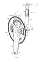
図1に示されるとおり、自転車のクランクアッセンブリ10は、自転車用電気装置40と、クランク部品12とを含む。
A bicycle crank
As shown in FIG. 1, the bicycle crank
クランク部品12は、クランクアーム14を含む。クランク部品12は、クランクアッセンブリ10を構成する。一例では、クランク部品12は、クランク軸16をさらに含む。クランク部品12は、フロントスプロケット18をさらに含んでいてもよい。クランク部品12の少なくとも一部は、金属材料によって形成されている。金属材料は、例えばアルミニウムを含む。一例では、クランクアーム14は、アルミニウム合金によって形成され、少なくとも一部、例えばクランクアーム14の表面にはアルマイト処理が施されている。クランク部品12の少なくとも一部、例えばクランクアーム14は、樹脂材料によって形成されていてもよい。樹脂材料は、炭素繊維強化プラスチック材料を含む。
The
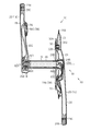
クランクアーム14は、第1クランクアーム20および第2クランクアーム22を含む。一例では、自転車の進行方向に向かって、第1クランクアーム20は、自転車のフレームF(図5参照)の右側に設けられ、第2クランクアーム22は、自転車のフレームFの左側に設けられる。
The
第1クランクアーム20は、アーム本体24およびフロントスプロケット18を接続する複数の接続部26を有する。アーム本体24の長手方向の第1端部24Aには、ペダル軸を取り付けるための孔24Cが形成されている。孔24Cを定義するアーム本体24の内周部には、雌ねじが形成されている。アーム本体24の長手方向の第2端部24Bには、クランク軸16を取り付けるための孔24D(図2参照)が形成されている。孔24Dを定義するアーム本体24の内周部は、クランク軸16の軸方向の一方の外周部に設けられているスプラインと結合するスプラインを含む。クランク軸16の軸方向の一端部は、例えば孔24Dに圧入されて第1クランクアーム20と固定される。クランク軸16の軸方向の一端部は、たとえば孔24Dに挿入された状態で、ボルトなどの固定部材によって第1クランクアーム20に固定されてもよい。アーム本体24の長手方向の第2端部24Bには、複数の接続部26がアーム本体24と一体に形成されている。複数の接続部26は、第2端部24Bからクランク軸16の径方向に放射状に延びる。一例では、接続部26は、4つ設けられる。各接続部26のクランク軸16の径方向外側の端部には、フロントスプロケット18が着脱可能に取り付けられる。フロントスプロケット18は、第1クランクアーム20とワンピース構造で構成されていてもよい。第1クランクアーム20は、中空に形成されることが好ましい。
The
第2クランクアーム22は、アーム本体28を有する。アーム本体28の長手方向の第1端部28Aには、ペダル軸を取り付けるための孔28Cが形成される。孔28Cを定義するアーム本体28の内周部には、雌ねじが形成されている。アーム本体28の長手方向の第2端部28Bには、クランク軸16を取り付けるための孔28Dが形成されている。孔28Dを定義するアーム本体28の内周部は、クランク軸16の軸方向の他方の外周部に設けられているスプラインと結合するスプラインを含む。第2クランクアーム22は、中空に形成されることが好ましい。クランク軸16は、中空に形成されるのが好ましい。クランク軸16の軸方向の他端部は、たとえば孔28Dに挿入された状態で、ボルトB(図2参照)などの固定部材によって第2クランクアーム22に固定される。
The
一例では、フロントスプロケット18は、歯数の異なる複数のフロントスプロケット18を含む。例えば、フロントスプロケット18は、第1フロントスプロケット30および第2フロントスプロケット32を含む。第1フロントスプロケット30は、複数の歯が設けられる外周部30A、および、外周部30Aから径方向内側に延びる複数の接続部30Bを含む。第2フロントスプロケット32は、複数の歯が設けられる外周部32A、および、外周部32Aから径方向内側に延びる複数の接続部32Bを含む。複数の接続部30B,32Bは、第1クランクアーム20の複数の接続部26に取り付けられる。第1フロントスプロケット30の歯数は、第2フロントスプロケット32の歯数よりも多い。第1フロントスプロケット30は、第2フロントスプロケット32よりも自転車の幅方向の外側に設けられる。
In one example, the
図2および図5に示されるとおり、自転車用電気装置40は、複数の端子42と、電気回路44と、を含む。一例では、自転車用電気装置40は、充電池46、ハウジング48、図8に示す磁性部98、カバー52、および、接続部材54をさらに含む。
As shown in FIGS. 2 and 5, the bicycle
図5に示されるとおり、電気回路44は、無線ユニット56を含む。電気回路44は、センサ58をさらに含む。電気回路44には、充電池46から電力が供給される。電気回路44は、第1回路部分60、および、第2回路部分62をさらに含む。
As shown in FIG. 5, the
センサ58は、クランクアッセンブリ10に設けられ、クランクアッセンブリ10にかかる力に応じた信号を出力する。センサ58は、第1センサ58Aおよび第2センサ58Bを含む。
The
図3に示されるとおり、第1センサ58Aは、第1クランクアーム20に設けられる。具体的には、第1センサ58Aは、第1クランクアーム20のアーム本体24の長手方向の中間部分において、自転車の幅方向において自転車のフレームFに対向する部分に設けられる。第1センサ58Aは、歪センサを含む。第1センサ58Aは、アーム本体24の歪みに応じた信号を出力する。歪センサは、例えば歪ゲージ、半導体センサまたは圧電センサを含む。第1センサ58Aは、例えば第1クランクアーム20の回転方向の上流側および下流側の少なくとも一方の側面部に設けられてもよく、自転車の幅方向において自転車のフレームFとは反対側の部分に設けられてもよい。第1クランクアーム20が中空クランクアームの場合、第1センサ58Aは、第1クランクアーム20の内部の内周面に設けられてもよい。第1センサ58Aは、検出方向が異なる複数の歪センサを含み、第1クランクアーム20の回転方向、長手方向、回転方向および長手方向に垂直な方向の少なくともいずれかに作用する力に応じた信号を出力するのが好ましい。
As shown in FIG. 3, the
図5に示されるとおり、第1回路部分60は、第1クランクアーム20に設けられる。第1回路部分60は、第1センサ58Aと接続される。第1回路部分60は、増幅回路64、アナログ-デジタル(A/D)変換回路66、および、演算部68を含む。増幅回路64、A/D変換回路66、および、演算部68は、同一の第1回路基板61上に設けられることが好ましい。一例では、第1回路部分60および第1センサ58Aは、共通のパッケージ72に覆われる。増幅回路64は、第1センサ58Aと接続され、第1センサ58Aの出力を増幅して出力する。A/D変換回路66は、増幅回路64の出力をデジタル信号に変換して演算部68に出力する。演算部68は、予め定められる制御プログラムを実行する演算処理装置を含む。演算処理装置は、例えばCPU(Central Processing Unit)またはMPU(Micro Processing Unit)を含む。演算部68は、1または複数のマイクロコンピュータを含んでいてもよい。演算部68は、制御プログラムを記憶したり、演算処理結果を記憶したりするメモリを含んでいてもよい。
As shown in FIG. 5, the
第1回路部分60は、回転センサ70をさらに含む。回転センサ70は、自転車のフレームF(図5参照)に対するクランクアッセンブリ10の回転位置を検出する。回転センサ70は、自転車のフレームFに取り付けられる磁石Mの磁界を検出する素子(図示略)を含む。素子は、例えばリードスイッチまたはホール素子を含む。素子は、クランクアッセンブリ10の1回転を1周期とした信号を演算部68に出力する。演算部68は、素子の出力信号に応じて、クランクアッセンブリ10の回転速度を定義したり、フレームFに対するクランクアッセンブリ10の回転位置を定義したりする。
The
図4に示されるとおり、第2センサ58Bは、第2クランクアーム22に設けられる。具体的には、第2センサ58Bは、第2クランクアーム22のアーム本体28の長手方向の中間部分において、自転車の幅方向において自転車のフレームFに対向する部分に設けられる。第2センサ58Bは、歪センサを含む。第2センサ58Bは、アーム本体28の歪みに応じた信号を出力する。第2センサ58Bは、例えば第2クランクアーム22の回転方向の上流側および下流側の少なくとも一方の側面部に設けられてもよく、自転車の幅方向において自転車のフレームFとは反対側の部分に設けられてもよい。第2クランクアーム22が中空クランクアームの場合、第2センサ58Bは、第2クランクアーム22の内部の内周面に設けられてもよい。第2センサ58Bは、検出方向が異なる複数の歪センサを含み、第2クランクアーム22の回転方向、長手方向、回転方向および長手方向に垂直な方向の少なくともいずれかに作用する力に応じた信号を出力するのが好ましい。
As shown in FIG. 4, the
図5に示されるとおり、第2回路部分62は、第2クランクアーム22に設けられる。第2回路部分62は、第2センサ58Bと接続される。第2回路部分62は、増幅回路74、A/D変換回路76を含む。増幅回路74およびA/D変換回路76は、同一の第2回路基板63上に設けられることが好ましい。一例では、第2回路部分62および第2センサ58Bは、共通のパッケージ78に覆われている。増幅回路74は、第2センサ58Bと接続され、第2センサ58Bの出力を増幅して出力する。A/D変換回路76は、増幅回路74の出力をデジタル信号に変換して第1回路部分60の演算部68に出力する。演算部68は、A/D変換回路66,76から入力されたデジタル信号に基づいた情報を無線ユニット56に出力する。
As shown in FIG. 5, the
無線ユニット56は、外部の無線通信装置Wと無線で通信可能に構成される。無線ユニット56は、無線通信部79を含む。無線通信の方式の一例は、BLUETOOTH(登録商標)およびANT+(登録商標)である。図6に示されるとおり、無線ユニット56は、ハウジング48に収容されて、第1クランクアーム20の隣り合う接続部26の間に設けられる。無線ユニット56には、報知部82およびスイッチ84が設けられる。一例では、報知部82は、LED(light emitting diode)を含む。報知部82は、例えばスイッチ84の操作によって演算部68がセンサ58のキャリブレーションを行う場合に、LEDを点灯してキャリブレーションの実行中であることをユーザに報知する。
The
一例では、図5に示す外部の無線通信装置Wは、サイクルコンピュータを含む。外部の無線通信装置Wは、制御部W1、無線通信部W2、入力部W3、表示部W4、および、スピーカW5を含む。制御部W1は、予め定められる制御プログラムを実行する演算処理装置を含む。演算処理装置は、例えばCPU(Central Processing Unit)またはMPU(Micro Processing Unit)を含む。制御部W1は、1または複数のマイクロコンピュータを含んでいてもよい。無線通信部W2は、無線ユニット56の無線通信部79との間で無線通信によって情報を送受信する。制御部W1は、無線通信部W2が無線ユニット56から受信した情報を表示部W4に表示する。例えば、制御部W1は、第1センサ58Aおよび第2センサ58Bが検出したクランク部品12に入力される力の大きさ、クランク部品12に入力される力の大きさおよびクランク部品12の回転速度から演算される仕事量などを表示部W4に表示させる。
In one example, the external wireless communication device W shown in FIG. 5 includes a cycle computer. The external wireless communication device W includes a control unit W1, a wireless communication unit W2, an input unit W3, a display unit W4, and a speaker W5. The control unit W1 includes an arithmetic processing unit that executes a predetermined control program. The arithmetic processing unit includes, for example, a CPU (Central Processing Unit) or an MPU (Micro Processing Unit). The control unit W1 may include one or more microcomputers. The wireless communication unit W2 transmits / receives information to / from the
充電池46は、クランクアッセンブリ10に設けられ、複数の端子42と電気的に接続される。充電池46は、電気回路44を介して複数の端子42と電気的に接続される。一例では、充電池46は、円柱形に形成される。充電池46は、クランク軸16の内部空間に配置される。充電池46は、1または複数の充電素子を含む。充電池46は、充電池ホルダ46Bに収容された状態で、クランク軸16の内部空間に配置される。充電池ホルダ46Bは、コネクタ46Aを含む。
The
ハウジング48には、コネクタ79Aが設けられる。コネクタ79Aには、無線通信部79が接続されている。第1回路部分60は、コネクタ60Aをさらに含む。コネクタ60Aは、第1クランクアーム20に配置される。図6に示されるとおり、コネクタ60Aは、第1クランクアーム20の隣り合う接続部26の間に設けられており、第1クランクアーム20の外部に露出する。図5に示されるとおり、コネクタ60Aは、電気ケーブル45Aによって増幅回路64、A/D変換回路66、および、演算部68が設けられる第1回路基板61に接続されている。電気ケーブル45Aの少なくとも一部は、第1クランクアーム20の内部空間に配置される。コネクタ79Aは、コネクタ60Aに接続されている。第1回路部分60は、電気ケーブル45Bによって充電池ホルダ46Bに接続されている。第1回路基板61と、充電池ホルダ46Bとが電気ケーブル45Bによって接続されている。第2回路部分62は、コネクタ62Aを更に含む。コネクタ62Aは、電気ケーブル45Cによって増幅回路74およびA/D変換回路76が設けられる第2回路基板63に接続されている。図4に示されるとおり、コネクタ62Aは、第2クランクアーム22の外部に露出する。電気ケーブル45Cの少なくとも一部は、第2クランクアーム22の内部空間に配置される。コネクタ62Aは、クランク軸16の内部空間において、充電池ホルダ46Bのコネクタ46Aに接続されている。図5に示されるとおり、無線通信部79、第1回路部分60、第2回路部分62が、電気ケーブル45A,45B,45Cの少なくともいずれかを介して充電池46と接続されており、無線通信部79、第1回路部分60、および、第2回路部分62には、充電池46からの電力が供給される。無線通信部79と第1回路部分60との間で、情報の送受信が行われる。第1回路部分60と第2回路部分62との間で、情報の送受信が行われる。無線通信部79、第1回路部分60、第2回路部分62、および、充電池46は、電力の供給と情報の送受信とが各別の電線によって行われる。無線通信部79、第1回路部分60、第2回路部分62、および、充電池46は、電力の供給と情報の送受信とが電力通信線を用いたPLC(Power Line Communication)によって行われてもよい。
The
図6に示すハウジング48は、絶縁体によって形成される。絶縁体は、例えば樹脂材料を含む。ハウジング48には、隣り合う2つの接続部26の間にハウジング48を取り付けるための取付部86が設けられる。取付部86は、貫通孔を含む。ボルトBが取付部86を貫通し、第1クランクアーム20の接続部26に設けられる雌ねじにねじ込まれることによって、ハウジング48が接続部26に取り付けられる。
The
図7に示されるとおり、ハウジング48は、第1ハウジング部分48Aおよび第2ハウジング部分48Bを含む。ハウジング48には、ハウジング48の一側部48F(図8参照)を覆うカバー52が取り付けられる。ハウジング48の一側部48Fは、自転車の幅方向において自転車のフレームFとは反対の方向に向いていることが好ましい。カバー52は、図8に示すヒンジ88によって、開閉可能にハウジング48に取り付けられている。ヒンジ88は、ハウジング48のうちのクランク軸16の径方向内側の端部に設けられることが好ましい。カバー52は、絶縁体によって形成される。カバー52には、第1孔52Aおよび第2孔52Bが形成されている。第1孔52Aは、報知部82と対応する位置に形成される。第1孔52Aによって、カバー52が閉められた状態でユーザが報知部82を外部から視認できる。第2孔52Bは、スイッチ84と対応する位置に形成される。スイッチ84の一部は、カバー52が閉められた状態で第2孔52Bを挿通する。第2孔52Bによって、カバー52が閉められた状態でユーザがスイッチ84を操作できる。カバー52は、ハウジング48に着脱可能に係合する係合部が設けられることが好ましく、係合部は、カバー52が閉められた状態でハウジング48の一部に係合するように構成される。一例では、係合部は、カバー52のうちのヒンジ88に取り付けられる部分とは反対側の端部に設けられる。
As shown in FIG. 7, the
図10に示されるとおり、第1ハウジング部分48Aおよび第2ハウジング部分48Bは、それぞれ凹部を有する。第1ハウジング部分48Aの凹部および第2ハウジング部分48Bの凹部が対向するように互いが組み付けられることによってハウジング48の内部に収容空間48Sが形成される。収容空間48Sには、無線通信部79(図5参照)が実装される基板56Aが収容される。
As shown in FIG. 10, the
ハウジング48には、複数の端子42が設けられる。複数の端子42は、少なくとも一部がハウジング48に形成される孔90から露出して設けられる。孔90は、第1ハウジング部分48Aに設けられる。孔90は、第1ハウジング部分48Aを貫通する。複数の端子42は、外部装置A(図5参照)に電気的に接続可能である。複数の端子42は、第1端子92および第2端子94を含む。孔90は、第1端子92を露出させるための第1孔90A、および、第2端子94を露出させるための第2孔90Bを含む。孔90は、ハウジング48の一側部48Fに開口する。複数の端子42は、ハウジング48の一側部48Fから露出する。複数の端子42は、その一部が孔90に配置される。第1端子92の少なくとも一部は、第1孔90Aに配置される。第2端子94の少なくとも一部は、第2孔90Bに配置される。各孔90には、各端子92,94とハウジング48との間の隙間を塞ぐためのシール部材49が設けられる。シール部材49は、絶縁性の弾性体によって形成される。絶縁性の弾性体は、例えば合成ゴムを含む。複数の端子42は、カバー52が閉じている状態で、カバー52によって覆われる。
The
図5に示されるとおり、第1端子92および第2端子94は、外部装置Aに接続される。第1端子92は、外部装置Aの正極と接続される。第2端子94は、外部装置Aの負極と接続される。具体的には、第1端子92は、外部装置AのコネクタA1の正極端子A2と接続され、第2端子94は、外部装置AのコネクタA1の負極端子A3と接続される。外部装置Aは、充電器およびコネクタA1を含む。複数の端子42には、外部装置AのコネクタA1の正極端子A2および負極端子A3が接続されることによって、電力が供給される。第2端子94は、電気回路44において、グラウンドと接続される。
As shown in FIG. 5, the
電気回路44は、複数の端子42に電気的に接続される。具体的には、図10に示されるとおり、複数の端子42のそれぞれの一端部がハウジング48の収容空間48S内において無線ユニット56が実装されている基板56Aに接続されている。複数の端子42は、基板56Aを貫通して基板56Aに接続されていてもよい。基板56Aには、充電回路96(図5参照)が設けられている。充電回路96は、充電池46(図5参照)に電気的に接続されている。複数の端子42を介して充電回路96に供給された外部装置Aからの電力は、充電回路96を経て充電池46に供給され、充電池46を充電する。充電回路96は、第1回路基板61に実装されてもよい。充電回路96は、たとえばバリスタおよび充電制御用のIC(Integrated Circuit)を含む。
The
図8に示す複数の端子42のうちの所定の端子は、クランク部品12と電気的に接続されている。所定の端子は、接続部材54を介して、クランク部品12と電気的に接続されている。所定の端子は、第1端子92および第2端子94の一方を含む。好ましくは、所定の端子は、第2端子94を含む。
A predetermined terminal among the plurality of
図9に示されるとおり、接続部材54は、所定の端子と別体に形成される。接続部材54の導電性は、複数の端子42の導電性と同等、または複数の端子42の導電性よりも低いことが好ましい。接続部材54の導電性は、複数の端子42よりも高くてもよい。接続部材54の導電性は、ハウジング48の導電性よりも高いことが好ましい。一例では、接続部材54は、金属材料によって形成される。金属材料は、例えばステンレス材料を含む。接続部材54は、第1部分54Aを含む。一例では、接続部材54は、第2部分54B、第3部分54C、および、第4部分54Dをさらに含む。第2部分54Bは、複数設けられる。第3部分54Cは、第1部分54Aと第2部分54Bと一体に形成される。接続部材54は、板金によって形成される。接続部材54は、板金が曲げ加工されることによって形成される。
As shown in FIG. 9, the connecting
第3部分54Cは、ベース部54Eと、ベース部54Eの両端部からそれぞれ突出する突出部54Fとを含む。ベース部54Eおよび突出部54Fは、同一平面上に形成されている。第4部分54Dは、ベース部54Eの両端部間の中間部に連なり、突出部54Fとは反対側に突出する。第4部分54Dの形状は特に限定されないが、例えば四角形に形成される。第3部分54Cおよび第4部分54Dは、同一平面上に形成されている。第1部分54Aは、L字形に形成されている。第1部分54Aは、第3部分54Cの厚み方向の一方の表面側に突出している。第1部分54Aの先端部は、第3部分54Cの突出部54Fとは反対側に延びている。第2部分54Bは、複数設けられる。第2部分54Bは、第3部分54Cの突出部54Fの先端から第3部分54Cの厚み方向の他方の表面側に突出している。板金を折り曲げて、第1部分54Aおよび第2部分54Bを形成する場合、例えば第1部分54Aと第3部分54Cとのなす角度DAが90度になるように板金を折り曲げ、第2部分54Bと第3部分54Cとのなす角度DBが、90度以上となるように板金を折り曲げる。
The
接続部材54は、所定の端子とクランク部品12とを電気的に接続するように構成される。接続部材54は、所定の端子との間の距離およびクランク部品12との間の距離が、1mm以下になるように設けられる。好ましくは、接続部材54は、所定の端子およびクランク部品12のそれぞれに接触する。接続部材54が所定の端子およびクランク部品12のそれぞれに接触する場合、接続部材54と所定の端子との間の距離およびクランク部品12との間の距離は、それぞれ「0」mmである。
The connecting
接続部材54は、所定の端子のうち孔90から露出する先端面42Aを除く部分に電気的に接続するように構成される。具体的には、図10に示されるとおり、第1部分54Aが、少なくとも一部が所定の端子と孔90の内壁との間に配置されて、所定の端子と電気的に接続される。図8に示されるとおり、ハウジング48には孔90の伸びる方向に対して交差する方向に、孔90に連なるスリット48Dが形成されている。第1部分54Aはスリット48Dを通過して、孔90にその一部が配置されている。
The connecting
図11に示されるとおり、第2部分54Bは、少なくとも一部がハウジング48とクランク部品12との間に挟まれて、クランク部品12と電気的に接続される。第2部分54Bの2つの突出部54Fの間には、ヒンジ88が配置されている。
As shown in FIG. 11, the
図8に示されるとおり、第3部分54Cは、少なくとも一部がハウジング48の一側部48Fの表面に配置される。第4部分54Dは、第3部分54Cに設けられ、ハウジング48に形成される凹部48Cに嵌め込まれる。凹部48Cは、第1端子92と第2端子94との間に形成される。接続部材54の少なくとも一部、例えば第1部分54A、第3部分54C、および、第4部分54Dは、カバー52が閉じている状態で、カバー52によって覆われる。
As shown in FIG. 8, the
磁性部98は、複数の端子42の近傍に設けられ、外部装置AのコネクタA1(図3参照)を吸着する。磁性部98は、たとえば鉄を含む。コネクタA1は、永久磁石を含む。磁性部98は、永久磁石を含んでもよい。磁性部98は、凹部48Cにおいてハウジング48との間に第4部分54Dを挟むように設けられる。磁性部98は、カバー52が閉じている状態で、カバー52によって覆われる。
The
(変形例)
上記実施形態に関する説明は、本発明に従う自転車用電気装置およびクランクアッセンブリが取り得る形態の例示であり、その形態を制限することを意図していない。本発明に従う自転車用電気装置およびクランクアッセンブは、例えば以下に示される上記実施形態の変形例、および、相互に矛盾しない少なくとも2つの変形例が組み合わせられた形態を取り得る。以下の変形例において、実施形態の形態と共通する部分については、実施形態と同一の符号を付してその説明を省略する。
(Modification example)
The description of the above embodiments is an example of possible embodiments of the bicycle electrical device and crank assembly according to the present invention, and is not intended to limit the embodiments. A bicycle electrical device and a crank assembly according to the present invention may take, for example, a modification of the above embodiment shown below and a combination of at least two modifications that are consistent with each other. In the following modification, the parts common to the embodiment are designated by the same reference numerals as those in the embodiment, and the description thereof will be omitted.
・接続部材54を省略し、所定の端子をクランク部品12と電気的に接続してもよい。図12に示す第2端子94Aは、先端面42Aからクランク部品12に向かって延びる延長部94Bを含む。延長部94Bの先端は、クランク部品12と電気的に接続される。延長部94Bの先端とクランク部品12との距離は1mm以下である。
-The
・第1センサ58Aおよび第2センサ58Bの一方を省略することもできる。第2センサ58Bを省略する場合、第2回路部分62も省略してもよい。第1センサ58Aを省略する場合、第1回路部分60を省略し、演算部68および回転センサ70を第2回路部分62に設けることもできる。回転センサ70は、第1回路基板61ではなく、ハウジング48に収容されている基板56Aに設けてもよく、第2回路基板63に設けてもよく、第1回路基板61、第2回路基板63、および、基板56Aとは独立して設けてもよい。
-One of the
・接続部材54を所定の端子と一体に形成してもよい。
・接続部材54の第1部分54A、第2部分54B、および、第3部分54Cを別体に形成し、連結部材によって組み付けたり、接合したりしてもよい。連結部材は、例えばボルトおよびリベットなどを含む。接合は、導電性接着剤による接着、半田による接合および溶接を含む。
-The connecting
The
・第2端子94に代えて、第1端子92を所定の端子としてクランク部品12に電気的に接続してもよい。
・複数の端子42を、充電用の端子ではなく、外部装置との通信用の端子としてもよい。この場合、充電池46は、一次電池に変更されてもよく、充電するために充電池ホルダ46Bから着脱可能に構成されてもよい。複数の端子42を、充電用の端子と、外部装置との通信用の端子とを兼ねる端子としてもよい。
-Instead of the
-The plurality of
・充電池46は、クランクアーム14に設けることもできる。この場合、クランクアーム14の内部空間に設けてもよく、クランクアーム14の外側に取り付けてもよい。例えば充電池46は、パッケージ72,78の少なくともいずれか一方に収容されて設けられてもよい。
-The
・自転車用電気装置40から磁性部98を省略してもよい。この場合、ハウジング48の一側部48Fに凹部を設け、複数の端子42を凹部の底部に設けて、外部装置AのコネクタA1を凹部に挿入して複数の端子42をコネクタA1と接続することもできる。またハウジング48およびコネクタA1のいずれか一方に爪部を設け、他方に爪部が係合する凹部を設ける構成としてもよい。
-The
・ハウジング48に所定の端子を設けているが、パッケージ72,78のいずれか一方に、所定の端子を設けてもよい。この場合、例えば無線通信部79および充電回路96を、パッケージ72,78に収容して、ハウジング48を省略してもよい。例えば、パッケージ72に、充電池46、無線通信部79、充電回路96、所定の端子を設けて、第2回路部分62を省略した形態も可能である。このような形態では、第1クランクアーム20、第2クランクアーム22のいずれか一方にのみに電気回路44を設けることもできる。
-Although the
・無線通信部79および充電回路96を第1回路基板61に設け、ハウジング48を省略して、クランクアーム14から直接的に所定の端子が露出する構成としてもよい。
The
・自転車用電気装置40からカバー52およびヒンジ88を省略してもよい。
・無線ユニット56から報知部82およびスイッチ84の少なくとも一方を省略してもよい。
The
-At least one of the
・ハウジング48は、クランクアーム14の隣り合う接続部26の間ではなく、少なくとも1つの接続部26に設けられてもよく、フロントスプロケット18に設けられてもよく、アーム本体24,28に設けられてもよい。
The
・第1回路部分60および第2回路部分62の少なくとも一方は、充電池46との電力供給経路に充電池46から供給される電力の電圧を調整するレギュレータを含んでいてもよい。
-At least one of the
・接続部材54から第4部分54Dを省略してもよい。接続部材54は、接着、一体成型、または連結部材によってハウジング48に固定されていてもよい。連結部材は、例えばボルトおよびリベット等を含む。
・接続部材54の第2部分54Bは、1つのみ設けられてもよく、3つ以上設けられてもよい。
The
-Only one
・接続部材54は、第1部分54Aが所定の端子のうちの孔90から露出する先端面42Aに電気的に接続するように構成されていてもよい。
・接続部材54の第2部分54Bは、ハウジング48とクランク部品12との間に挟まれず、クランク部品12の表面に接触するように構成されてもよい。
The connecting
The
・センサ58をクランク軸16に設ける構成としてもよい。この場合、センサ58は、クランク軸16のねじれを検出する構成としてもよい。
The
10…クランクアッセンブリ、12…クランク部品、14…クランクアーム、26…接続部、16…クランク軸、18…フロントスプロケット、40…自転車用電気装置、42…複数の端子、42A…先端面、44…電気回路、46…充電池、48…ハウジング、48C…凹部、48F…一側部、54…接続部材、54A…第1部分、54B…第2部分、54C…第3部分、54D…第4部分、56…無線ユニット、58…センサ、86…取付部、92…第1端子、94…第2端子(所定の端子)、90…孔、98…磁性部、A…外部装置、A1…コネクタ、W…無線通信装置。 10 ... Crank assembly, 12 ... Crank parts, 14 ... Crank arm, 26 ... Connection, 16 ... Crank shaft, 18 ... Front sprocket, 40 ... Bicycle electrical device, 42 ... Multiple terminals, 42A ... Tip surface, 44 ... Electric circuit, 46 ... Rechargeable battery, 48 ... Housing, 48C ... Recess, 48F ... One side, 54 ... Connecting member, 54A ... 1st part, 54B ... 2nd part, 54C ... 3rd part, 54D ... 4th part , 56 ... wireless unit, 58 ... sensor, 86 ... mounting part, 92 ... first terminal, 94 ... second terminal (predetermined terminal), 90 ... hole, 98 ... magnetic part, A ... external device, A1 ... connector, W ... Wireless communication device.
Claims (23)
外部装置に電気的に接続可能な複数の端子と、
前記複数の端子に電気的に接続されている電気回路と、を含み、
前記複数の端子のうちの所定の端子は、前記クランク部品と電気的に接続されている、自転車用電気装置。 An electric device for a bicycle that is provided on a crank component constituting a crank assembly of a bicycle so as to rotate integrally with the crank component .
With multiple terminals that can be electrically connected to external devices,
Includes an electrical circuit that is electrically connected to the plurality of terminals.
A bicycle electric device in which a predetermined terminal among the plurality of terminals is electrically connected to the crank component.
前記複数の端子は、少なくとも一部が前記ハウジングに形成される孔から露出して設けられ、
前記接続部材は、前記所定の端子のうち前記孔から露出する先端面を除く部分に電気的に接続するように構成される、請求項2に記載の自転車用電気装置。 The plurality of terminals are provided and further include a housing formed of an insulator.
The plurality of terminals are provided so that at least a part thereof is exposed from a hole formed in the housing.
The electric device for a bicycle according to claim 2 , wherein the connecting member is configured to be electrically connected to a portion of the predetermined terminal other than the tip surface exposed from the hole.
外部装置に電気的に接続可能な複数の端子と、
前記複数の端子に電気的に接続されている電気回路と、
前記複数の端子が設けられ、絶縁体によって形成されるハウジングと、
前記所定の端子と前記クランク部品とを電気的に接続するように構成される接続部材と、を含み、
前記複数の端子のうちの所定の端子は、前記クランク部品と電気的に接続され、
前記複数の端子は、少なくとも一部が前記ハウジングに形成される孔から露出して設けられ、
前記接続部材は、前記所定の端子のうち前記孔から露出する先端面を除く部分に電気的に接続するように構成される、自転車用電気装置。 An electric device for bicycles provided in the crank parts that make up the crank assembly of a bicycle.
With multiple terminals that can be electrically connected to external devices,
An electric circuit electrically connected to the plurality of terminals and
A housing in which the plurality of terminals are provided and formed of an insulator,
Includes a connecting member configured to electrically connect the predetermined terminal to the crank component .
A predetermined terminal among the plurality of terminals is electrically connected to the crank component and is connected to the crank component .
The plurality of terminals are provided so that at least a part thereof is exposed from a hole formed in the housing.
The connecting member is an electric device for a bicycle that is configured to be electrically connected to a portion of the predetermined terminal other than the tip surface exposed from the hole .
前記ハウジングには、隣り合う2つの前記接続部の間に前記ハウジングを取り付けるための取付部が設けられる、請求項6〜10のいずれか一項に記載の自転車用電気装置。 The crank component includes a crank arm having a plurality of connections for connecting the front sprocket.
The electric device for a bicycle according to any one of claims 6 to 10 , wherein the housing is provided with a mounting portion for mounting the housing between two adjacent connecting portions.
前記複数の端子は、前記外部装置の正極と接続される第1端子、および、前記外部装置の負極と接続される第2端子を含み、
前記所定の端子は、前記第1端子および前記第2端子の一方を含む、請求項1〜15のいずれか一項に記載の自転車用電気装置。 The external device includes a charger and
The plurality of terminals include a first terminal connected to the positive electrode of the external device and a second terminal connected to the negative electrode of the external device.
The electric device for a bicycle according to any one of claims 1 to 15 , wherein the predetermined terminal includes one of the first terminal and the second terminal.
前記クランク部品とを含み、
前記クランク部品は、クランクアームを含む、クランクアッセンブリ。 The bicycle electrical device according to any one of claims 1 to 21 .
Including the crank parts
The crank component is a crank assembly including a crank arm.
Priority Applications (2)
| Application Number | Priority Date | Filing Date | Title |
|---|---|---|---|
| JP2017040799A JP6767287B2 (en) | 2017-03-03 | 2017-03-03 | Bicycle electrical equipment and crank assembly including this equipment |
| DE102018104191.8A DE102018104191A1 (en) | 2017-03-03 | 2018-02-23 | An electric bicycle device and crank assembly comprising the electric bicycle device |
Applications Claiming Priority (1)
| Application Number | Priority Date | Filing Date | Title |
|---|---|---|---|
| JP2017040799A JP6767287B2 (en) | 2017-03-03 | 2017-03-03 | Bicycle electrical equipment and crank assembly including this equipment |
Publications (3)
| Publication Number | Publication Date |
|---|---|
| JP2018144614A JP2018144614A (en) | 2018-09-20 |
| JP2018144614A5 JP2018144614A5 (en) | 2019-04-25 |
| JP6767287B2 true JP6767287B2 (en) | 2020-10-14 |
Family
ID=63171088
Family Applications (1)
| Application Number | Title | Priority Date | Filing Date |
|---|---|---|---|
| JP2017040799A Active JP6767287B2 (en) | 2017-03-03 | 2017-03-03 | Bicycle electrical equipment and crank assembly including this equipment |
Country Status (2)
| Country | Link |
|---|---|
| JP (1) | JP6767287B2 (en) |
| DE (1) | DE102018104191A1 (en) |
Families Citing this family (5)
| Publication number | Priority date | Publication date | Assignee | Title |
|---|---|---|---|---|
| JP6939735B2 (en) | 2017-08-01 | 2021-09-22 | 株式会社デンソー | Magnet manufacturing method |
| JP7353795B2 (en) * | 2019-05-15 | 2023-10-02 | 株式会社シマノ | Pedaling device for human-powered vehicles and pedaling system for human-powered vehicles |
| US11591042B2 (en) * | 2019-09-11 | 2023-02-28 | Shimano Inc. | Power supply device for human-powered vehicle |
| JP7438837B2 (en) | 2020-04-23 | 2024-02-27 | 株式会社シマノ | Components for human-powered vehicles |
| JP7467216B2 (en) * | 2020-04-23 | 2024-04-15 | 株式会社シマノ | Components for human-powered vehicles |
Family Cites Families (8)
| Publication number | Priority date | Publication date | Assignee | Title |
|---|---|---|---|---|
| JPH08164886A (en) * | 1994-12-12 | 1996-06-25 | Nippondenso Co Ltd | Bicycle with electric auxiliary motive power |
| JP4847156B2 (en) * | 2006-02-28 | 2011-12-28 | 株式会社シマノ | Bicycle crankshaft assembly |
| JP2008221880A (en) * | 2007-03-08 | 2008-09-25 | Willcom Inc | Pedal of bicycle having built-in position information transmitting device, and mobile communication system providing position information of bicycle |
| US8584529B2 (en) * | 2007-07-06 | 2013-11-19 | Mark Fisher | Crank arm with strain amplifier |
| JP5618405B2 (en) * | 2010-08-25 | 2014-11-05 | シリコン・バレイ・マイクロ・イー・コーポレーション | Bicycle power meter with frame mounting sensor |
| KR101343103B1 (en) * | 2013-07-02 | 2013-12-20 | (주)에스피에스 | Charging system having a circuit for delaying power supply |
| EP3259178A4 (en) * | 2015-02-18 | 2018-03-21 | Willem Den Boer | Pedal-driven vehicle crank |
| US9771126B2 (en) * | 2015-05-27 | 2017-09-26 | Shimano Inc. | Bicycle crank assembly |
-
2017
- 2017-03-03 JP JP2017040799A patent/JP6767287B2/en active Active
-
2018
- 2018-02-23 DE DE102018104191.8A patent/DE102018104191A1/en active Pending
Also Published As
| Publication number | Publication date |
|---|---|
| JP2018144614A (en) | 2018-09-20 |
| DE102018104191A1 (en) | 2018-09-06 |
Similar Documents
| Publication | Publication Date | Title |
|---|---|---|
| JP6767287B2 (en) | Bicycle electrical equipment and crank assembly including this equipment | |
| US9285401B2 (en) | Current detecting device and attaching structure thereof | |
| JP5051640B2 (en) | Electronics | |
| US6868744B2 (en) | Magnetic torque sensor including integral sub-unit | |
| US10714796B2 (en) | Battery temperature sensor and attachment structure thereof | |
| US20160003696A1 (en) | Crank Arm Electronics Packaging | |
| JP5435825B2 (en) | Connector and connector assembly | |
| US9580138B2 (en) | Bicycle crank assembly | |
| JP5403792B2 (en) | Current detector assembly structure | |
| ITUB20160088A1 (en) | Bicycle pedaling force detector | |
| EP3300143B1 (en) | Battery state sensing device and manufacturing method therefor | |
| CN110466662B (en) | Bicycle crank arm and related crank set | |
| WO2008021230A3 (en) | Battery with integrally formed terminal | |
| US11187601B2 (en) | Sensor device | |
| JP2013143997A (en) | Body wearable device | |
| JP6462946B1 (en) | Force sensor | |
| JP6015008B2 (en) | Sensor | |
| US10627298B2 (en) | Torque sensor | |
| JP6488057B1 (en) | Force sensor | |
| US20110273854A1 (en) | Magnetic Field Sensor | |
| JP2013148556A5 (en) | ||
| CN210971266U (en) | Torque angle sensor | |
| WO2015186421A1 (en) | Battery state measuring device and battery provided with same | |
| JP5376475B2 (en) | Contact pad and cell module assembly for voltage sensing of cell module assembly | |
| JP2007057461A (en) | Pressure sensor |
Legal Events
| Date | Code | Title | Description |
|---|---|---|---|
| A521 | Request for written amendment filed |
Free format text: JAPANESE INTERMEDIATE CODE: A523 Effective date: 20190313 |
|
| A621 | Written request for application examination |
Free format text: JAPANESE INTERMEDIATE CODE: A621 Effective date: 20190313 |
|
| A977 | Report on retrieval |
Free format text: JAPANESE INTERMEDIATE CODE: A971007 Effective date: 20200213 |
|
| A131 | Notification of reasons for refusal |
Free format text: JAPANESE INTERMEDIATE CODE: A131 Effective date: 20200401 |
|
| A521 | Request for written amendment filed |
Free format text: JAPANESE INTERMEDIATE CODE: A523 Effective date: 20200519 |
|
| TRDD | Decision of grant or rejection written | ||
| A01 | Written decision to grant a patent or to grant a registration (utility model) |
Free format text: JAPANESE INTERMEDIATE CODE: A01 Effective date: 20200915 |
|
| A61 | First payment of annual fees (during grant procedure) |
Free format text: JAPANESE INTERMEDIATE CODE: A61 Effective date: 20200917 |
|
| R150 | Certificate of patent or registration of utility model |
Ref document number: 6767287 Country of ref document: JP Free format text: JAPANESE INTERMEDIATE CODE: R150 |
|
| R250 | Receipt of annual fees |
Free format text: JAPANESE INTERMEDIATE CODE: R250 |