JP6764656B2 - Suspension device for work equipment - Google Patents
Suspension device for work equipment Download PDFInfo
- Publication number
- JP6764656B2 JP6764656B2 JP2016014185A JP2016014185A JP6764656B2 JP 6764656 B2 JP6764656 B2 JP 6764656B2 JP 2016014185 A JP2016014185 A JP 2016014185A JP 2016014185 A JP2016014185 A JP 2016014185A JP 6764656 B2 JP6764656 B2 JP 6764656B2
- Authority
- JP
- Japan
- Prior art keywords
- body frame
- suspension
- axle
- vehicle body
- intermediate shaft
- Prior art date
- Legal status (The legal status is an assumption and is not a legal conclusion. Google has not performed a legal analysis and makes no representation as to the accuracy of the status listed.)
- Active
Links
Images


Description
本発明は、自走式作業機のサスペンション構造、特に、車体フレーム上に旋回体を備えた総車軸数3以上の自走式作業機のサスペンション構造に関する。 The present invention relates to a suspension structure of a self-propelled work machine, particularly a suspension structure of a self-propelled work machine having a swivel body on a vehicle body frame and having a total number of axles of 3 or more.
クレーン車等を初めとする自走式作業機は取り扱いの対象となる吊荷や積載物の大型化に伴って作業用の装備や車体フレームの高剛性化が要求され、この要求を満たすために車体重量が増加する傾向にあり、車両の足回りにも十分な強度が必要とされる。
また、その一方で、走行安定性を維持する必要上、自走式作業機の全高を可能な限り低く抑えたいという要求がある。
Self-propelled work machines such as crane vehicles are required to have work equipment and high rigidity of the body frame as the suspended load and the load to be handled become larger, and in order to meet this requirement. The weight of the vehicle body tends to increase, and sufficient strength is required for the undercarriage of the vehicle.
On the other hand, in order to maintain running stability, there is a demand to keep the total height of the self-propelled work machine as low as possible.
ここで、車両の足回りに十分な強度を与えるための手段としては、例えば、特許文献1に開示されるように、前軸を支える左右のサスペンションシリンダと後軸を支える左右のサスペンションシリンダの各々の一端(上端)を車体フレームの側方に延出する左右のサスペンションシリンダ取付ブラケットを介して車体フレームに取り付ける一方、これら左右のサスペンションシリンダの各々の他端(下端)を各輪の転舵の中心軸に沿って左右のキングピンの上端部に取り付けるようにした懸架装置が公知である。
その技術思想は、左右のサスペンションシリンダの各々の他端(下端)を各輪の転舵の中心軸に沿って左右のキングピンの上端部に取り付けることによって、左右のサスペンションシリンダの各々の他端(下端)をアクスルビームの左右の端部に取り付けていた従来型の懸架装置に比べ、車両の荷重を支える各々のサスペンションシリンダの他端(下端)と此れに対応する車輪との間の水平離間距離であるモーメントの腕の長さを短縮し、アクスルビームに作用する曲げモーメントを軽減してアクスルビームの実質的な耐久性を向上させる点にある。
Here, as means for imparting sufficient strength to the suspension of the vehicle, for example, as disclosed in Patent Document 1, the left and right suspension cylinders that support the front axle and the left and right suspension cylinders that support the rear axle, respectively. One end (upper end) of the left and right suspension cylinders is attached to the vehicle body frame via the left and right suspension cylinder mounting brackets that extend to the side of the vehicle body frame, while the other ends (lower ends) of each of these left and right suspension cylinders are used for steering of each wheel. Suspension devices that are attached to the upper ends of the left and right kingpins along the central axis are known.
The technical idea is that the other ends (lower ends) of the left and right suspension cylinders are attached to the upper ends of the left and right kingpins along the central axis of the steering of each wheel, so that the other ends (lower ends) of the left and right suspension cylinders are attached. Compared to the conventional suspension system in which the lower end) is attached to the left and right ends of the axle beam, the horizontal separation between the other end (lower end) of each suspension cylinder that supports the load of the vehicle and the corresponding wheel. The point is to shorten the arm length of the moment, which is the distance, reduce the bending moment acting on the axle beam, and improve the substantial durability of the axle beam.
更に、特許文献2では、特許文献1に開示される構成に加え、前軸を支える左右のサスペンションシリンダと後軸を支える左右のサスペンションシリンダの各々の一端(上端)を、車体フレームよりも上方に突出して側方に延出する左右のサスペンションシリンダ取付ブラケットを介して車体フレームに取り付けるようにすると共に、デフケースを車体フレームに固設し、デフケースの左右のドライブシャフトを相対変位可能な取り付け構造としてアクスルビームを省略し、ドライブシャフト周りの構造を小型化・小径化した上で、左右のドライブシャフトを車体フレームの左右の端面に貫通させる構造とするか、若しくは、車体フレームの直下を通す構造とすることで、車体フレームよりも下方に配置されるパーツを無くし、または、車体フレームよりも下方に突出するパーツを小型化・小径化して、作業機の全高を低く抑えるようにした懸架装置が提案されている。
Further, in
しかしながら、左右のサスペンションシリンダの各々の他端(下端)を各輪の転舵の中心軸に沿って左右のキングピンの上端部に取り付けることによって車両の荷重を支える各々のサスペンションシリンダの他端と車輪との間の水平離間距離であるモーメントの腕の長さを短縮してアクスルビームに作用する曲げモーメントを軽減するとした特許文献1の懸架装置の場合にあっては、左右のサスペンションシリンダの各々の他端(下端)の取付位置となるキングピンの上端部つまりナックルアーム等の上面の位置がアクスルビームよりも高くなることから、左右のサスペンションシリンダの各々の他端(下端)をアクスルビームの左右の端部に取り付けていた従来型の懸架装置に比べてサスペンションシリンダの伸縮ストロークが相対的に短くなる不都合がある。 However, the other ends and wheels of each suspension cylinder that support the load of the vehicle by attaching the other ends (lower ends) of the left and right suspension cylinders to the upper ends of the left and right kingpins along the central axis of steering of each wheel. In the case of the suspension device of Patent Document 1 in which the length of the arm of the moment, which is the horizontal separation distance between the two, is shortened to reduce the bending moment acting on the axle beam, each of the left and right suspension cylinders. Since the upper end of the kingpin, which is the mounting position of the other end (lower end), that is, the position of the upper surface of the knuckle arm, etc., is higher than the axle beam, the other ends (lower ends) of the left and right suspension cylinders are on the left and right sides of the axle beam. There is a disadvantage that the expansion / contraction stroke of the suspension cylinder is relatively short as compared with the conventional suspension device attached to the end portion.
これに対し、サスペンションシリンダの各々の一端(上端)を車体フレームよりも上方に突出して側方に延出する左右のサスペンションシリンダ取付ブラケットを介して車体フレームに取り付けるようにした特許文献2の懸架装置の場合では、サスペンションシリンダの各々の一端(上端)の取付位置が特許文1に見られる懸架装置の場合に比べて相対的に上方に移動することになるので、左右のサスペンションシリンダの各々の他端(下端)の取付位置をアクスルビームよりも上方のキングピンの上端部に移動させても、左右のサスペンションシリンダの伸縮ストロークを従来型の懸架装置と同程度に維持することができる。
On the other hand, the suspension device of
しかし、特許文献2に開示される懸架装置は、専ら、総車軸数2の自走式作業機のサスペンション構造を前提として考案されたものであり、この技術を総車軸数3以上の自走式作業機に適用するのは必ずしも容易ではない。
例えば、前軸,中間軸,後軸を有する総車軸数3のクレーン車に特許文献2に開示される懸架装置を適用した場合、車体フレームの前後方向における略中間位置に配置された中間軸を支えるサスペンションシリンダを取り付けるためのサスペンションシリンダ取付ブラケットが車体フレームよりも上方に突出することになるので、中間軸のサスペンションシリンダ取付ブラケットが、車体フレーム上の旋回体の回転によって旋回体の下面と干渉する恐れがあり、また、この干渉を防ぐために車体フレームと旋回体との間に大きなクリアランスを設定すると、作業機の全高が高くなって走行安定性が損なわれるといった不都合が生じてしまう。
However, the suspension device disclosed in
For example, when the suspension device disclosed in
そこで、本発明の目的は、総車軸数3以上で車体フレーム上に旋回体を備えた自走式作業機に適用した場合であっても、十分な伸縮ストロークを有し、作業機の全高を可能な限り低く抑えて車両の足回りに十分な強度を保証することのできる自走式作業機のサスペンション構造を提供することにある。 Therefore, an object of the present invention is to have a sufficient expansion / contraction stroke and to increase the total height of the work machine even when applied to a self-propelled work machine having a total number of axles of 3 or more and a swivel body on a vehicle body frame. The purpose is to provide a suspension structure for a self-propelled work machine that can be kept as low as possible to guarantee sufficient strength for the undercarriage of the vehicle.
本発明における自走式作業機のサスペンション構造は、車体フレーム上に旋回体を備えて前軸と後軸との間に1軸以上の中間軸を配置した総車軸数3以上の自走式作業機のサスペンション構造であり、
前記前軸を支える左右のサスペンションシリンダと前記後軸を支える左右のサスペンションシリンダの各々の一端が、前記車体フレームよりも上方に突出して側方に延出する左右のサスペンションシリンダ取付ブラケットを介して前記車体フレームに取り付けられる一方、これら左右のサスペンションシリンダの各々の他端が各輪の転舵の中心軸に沿って左右のキングピンの上端部に取り付けられると共に、
前記中間軸を支える左右のサスペンションシリンダの各々の一端が、前記車体フレームの側面に取り付けられる一方、これら左右のサスペンションシリンダの各々の他端が各輪の転舵の中心軸から内側にオフセットして前記中間軸のアクスルビームの左右の端部に取り付けられ、
前記車体フレームが、其の上面を覆う頂板、および、其の側面を覆う左右の側板を備えると共に、前記頂板が、前記中間軸を支える左右のサスペンションシリンダの各々の一端の取付箇所で前記左右の側板を越えて側方に延出してサスペンションシリンダ取付部を形成し、前記中間軸を支える左右のサスペンションシリンダの各々の前記一端が、其の上端面が前記サスペンションシリンダ取付部の下面に当接すると共に其の内側端面が前記左右の側板に当接し且つ其の外側端面が前記頂板から側方に突出しない大きさの中間軸用サスペンションシリンダ取付ブラケットを介して前記車体フレームの側面に取り付けられていることを特徴とする構成を有する。
The suspension structure of the self-propelled work machine in the present invention is a self-propelled work having a total number of axles of 3 or more, in which a swivel body is provided on a vehicle body frame and one or more intermediate axles are arranged between the front axle and the rear axle. The suspension structure of the aircraft
The left and right suspension cylinders that support the front axle and one ends of the left and right suspension cylinders that support the rear axle project via the left and right suspension cylinder mounting brackets that project upward from the vehicle body frame and extend laterally. While attached to the body frame, the other ends of each of these left and right suspension cylinders are attached to the upper ends of the left and right kingpins along the central axis of the steering of each wheel.
One end of each of the left and right suspension cylinders supporting the intermediate shaft is attached to the side surface of the vehicle body frame, while the other end of each of the left and right suspension cylinders is offset inward from the central axis of steering of each wheel. Attached to the left and right ends of the axle beam of the intermediate axis ,
The vehicle body frame includes a top plate covering the upper surface thereof and left and right side plates covering the side surfaces thereof, and the top plates are left and right at mounting points at one ends of the left and right suspension cylinders supporting the intermediate shaft. A suspension cylinder mounting portion is formed by extending laterally beyond the side plate, and one end of each of the left and right suspension cylinders supporting the intermediate shaft abuts its upper end surface on the lower surface of the suspension cylinder mounting portion. Rukoto its inner end face attached to a side surface of the body frame through the contact and the intermediate shaft for suspension cylinder mounting bracket its size outer end face does not project laterally from said top plate of said left and right side plates It has a structure characterized by.
車体フレームの前方に位置する前軸を支える左右のサスペンションシリンダと車体フレームの後方に位置する後軸を支える左右のサスペンションシリンダの各々の他端(下端)が各輪の転舵の中心軸に沿って左右のキングピンの上端部に取り付けられるので、前軸や後軸を支える各々のサスペンションシリンダの他端(下端)と車輪との間の水平離間距離であるモーメントの腕の長さが短縮され、前軸や後軸のアクスルビームに作用する曲げモーメントが軽減されて、前軸と後軸のアクスルビームの実質的な耐久性を向上させることができる。
また、これらのサスペンションシリンダの各々の一端(上端)が車体フレームよりも上方に突出して側方に延出する左右のサスペンションシリンダ取付ブラケットに取り付けられ、その取付位置がアクスルビームに比べて相対的に上方に移動することになるので、左右のサスペンションシリンダの伸縮ストロークが保証される。
一方、車体フレームの前後方向における略中間位置に配置された中間軸を支える左右のサスペンションシリンダの各々の一端(上端)は、車体フレームの側面に取り付けられ、これら左右のサスペンションシリンダの各々の他端(下端)が各輪の転舵の中心軸から内側にオフセットして中間軸のアクスルビームの左右の端部に取り付けられるので、車体フレームの前後方向における略中間位置に配置されたサスペンション構造の構成要素が車体フレームの上面を超えて上方に突出することはなく、車体フレーム上の旋回体が回転しても旋回体の下面とサスペンション構造の構成要素が干渉することがないので、車体フレームに密接させて旋回体を取り付けることが可能となり、作業機の全高を低く抑えて走行安定性を確保することができる。
中間軸を支える左右のサスペンションシリンダの各々の他端(下端)は中間軸のアクスルビームの左右の端部に取り付けられているため、中間軸のサスペンションシリンダの他端(下端)と車輪との間の水平離間距離であるモーメントの腕の長さは前軸や後軸の場合に比べると相対的に長くなるが、この中間軸は車両の重量の一部を支えるために付加されたものであり、この中間軸の増設によって各軸に作用する荷重は2軸の自走式作業機の場合と比べて相対的に軽減されているので、中間軸のアクスルビームに作用する曲げモーメントによって中間軸のアクスルビーム等の耐久性に支障が生じることはない。
そして、この3軸目以降の中間軸を設置することで、クレーン車等を初めとする自走式作業機が取り扱いの対象とする吊荷や積載物の大型化による高重量化に対処することができる。
中間軸の取付には、例えば、中間軸を支える左右のサスペンションシリンダの各々の一端(上端)の取付箇所で左右の側板を越えて側方に延出する車体フレームの頂板をサスペンションシリンダ取付部とし、中間軸を支える左右のサスペンションシリンダの各々の一端(上端)を、其の上端面がサスペンションシリンダ取付部の下面に当接すると共に其の内側端面が車体フレームの左右の側板に当接し且つ其の外側端面が頂板から側方に突出しない大きさの中間軸用サスペンションシリンダ取付ブラケットを介して車体フレームの側面に取り付けるといった構造が適用でき、このような構造を適用することにより、車体フレームの上面を超えてサスペンション構造の構成要素が上方に突出することを確実に防止することができる。そのうえ、車体フレームに密接させて旋回体を取り付けることが可能であり、作業機の全高を低く抑えて走行安定性を確保することができる。
車体フレームの頂板と一体に形成されたサスペンションシリンダ取付部の下面と車体フレームの側板の双方に当接させて中間軸用サスペンションシリンダ取付ブラケットが車体フレームに固着されるので、中間軸を支える左右のサスペンションシリンダを車体フレームの両側に強固に取り付けることができる。
The other ends (lower ends) of the left and right suspension cylinders that support the front axle located in front of the vehicle body frame and the left and right suspension cylinders that support the rear axle located behind the vehicle body frame are along the central axis of steering of each wheel. Since it is attached to the upper ends of the left and right kingpins, the length of the arm of the moment, which is the horizontal separation distance between the other end (lower end) of each suspension cylinder that supports the front axle and the rear axle, and the wheel is shortened. The bending moment acting on the axle beams of the front and rear axles is reduced, and the substantial durability of the axle beams of the front and rear axles can be improved.
In addition, one end (upper end) of each of these suspension cylinders is attached to the left and right suspension cylinder mounting brackets that project upward from the vehicle body frame and extend laterally, and the mounting position is relatively relative to the axle beam. Since it will move upward, the expansion and contraction strokes of the left and right suspension cylinders are guaranteed.
On the other hand, one end (upper end) of each of the left and right suspension cylinders supporting the intermediate shafts arranged at substantially intermediate positions in the front-rear direction of the vehicle body frame is attached to the side surface of the vehicle body frame, and the other ends of each of these left and right suspension cylinders. Since the (lower end) is offset inward from the central axis of the steering of each wheel and attached to the left and right ends of the axle beam of the intermediate axis, the suspension structure is arranged at a substantially intermediate position in the front-rear direction of the vehicle body frame. The elements do not protrude upward beyond the upper surface of the vehicle body frame, and even if the rotating body on the vehicle body frame rotates, the lower surface of the rotating body and the components of the suspension structure do not interfere with each other, so that the elements are closely attached to the vehicle body frame. It is possible to attach the swivel body to the suspension, and the overall height of the work equipment can be kept low to ensure running stability.
Since the other ends (lower ends) of the left and right suspension cylinders that support the intermediate shaft are attached to the left and right ends of the axle beam of the intermediate shaft, between the other ends (lower ends) of the suspension cylinder of the intermediate shaft and the wheels. The length of the arm of the moment, which is the horizontal separation distance of, is relatively longer than that of the front axle and the rear axle, but this intermediate axle is added to support a part of the weight of the vehicle. Since the load acting on each shaft is relatively reduced by the addition of this intermediate shaft as compared with the case of the two-axis self-propelled work machine, the bending moment acting on the axle beam of the intermediate shaft causes the intermediate shaft. There is no problem with the durability of the axle beam and the like.
Then, by installing the intermediate shafts after the third shaft, it is possible to cope with the increase in weight due to the increase in the size of the suspended load and the load to be handled by the self-propelled work machine such as a crane vehicle. Can be done.
For mounting the intermediate shaft, for example, the top plate of the vehicle body frame that extends laterally beyond the left and right side plates at the mounting location of each end (upper end) of the left and right suspension cylinders that support the intermediate shaft is used as the suspension cylinder mounting portion. , One end (upper end) of each of the left and right suspension cylinders that support the intermediate shaft, its upper end surface abuts on the lower surface of the suspension cylinder mounting portion, and its inner end surface abuts on the left and right side plates of the vehicle body frame. A structure can be applied in which the outer end surface is attached to the side surface of the vehicle body frame via a suspension cylinder mounting bracket for the intermediate shaft having a size that does not protrude laterally from the top plate. By applying such a structure, the upper surface of the vehicle body frame can be raised. It is possible to reliably prevent the components of the suspension structure from protruding upward beyond the limit. In addition, the swivel body can be attached in close contact with the vehicle body frame, and the overall height of the working machine can be kept low to ensure running stability.
Since the suspension cylinder mounting bracket for the intermediate shaft is fixed to the vehicle body frame by contacting both the lower surface of the suspension cylinder mounting portion integrally formed with the top plate of the vehicle body frame and the side plates of the vehicle body frame, the left and right sides that support the intermediate shaft Suspension cylinders can be firmly attached to both sides of the body frame.
望ましくは、中間軸に作用する軸重は、前軸に作用する軸重や後軸に作用する軸重よりも軽く設定する。 Desirably, the axle load acting on the intermediate shaft is set lighter than the axle load acting on the front axle and the axle load acting on the rear axle.
既に述べた通り、中間軸のサスペンションシリンダの他端(下端)と車輪との間の水平離間距離であるモーメントの腕の長さは前軸や後軸の場合に比べて長くなるが、中間軸に作用する軸重を前軸に作用する軸重や後軸に作用する軸重よりも軽く設定することにより、中間軸のアクスルビームに作用する曲げモーメントを前軸や後軸と同等の範囲に収めることができる。(モーメントの腕が長くなる半面、作用する荷重は軽減するため。) As already mentioned, the arm length of the moment, which is the horizontal separation distance between the other end (lower end) of the suspension cylinder of the intermediate shaft and the wheel, is longer than that of the front axle and the rear axle, but the intermediate shaft By setting the axle weight acting on the front axle lighter than the axle weight acting on the front axle and the axle weight acting on the rear axle, the bending moment acting on the axle beam of the intermediate shaft is within the same range as the front axle and the rear axle. Can fit. (While the arm of the moment becomes longer, the acting load is reduced.)
更に、前記前軸を支える左右のサスペンションシリンダと前記後軸を支える左右のサスペンションシリンダと前記中間軸を支える左右のサスペンションシリンダとを同一規格品で統一してもよい。 Further, the left and right suspension cylinders that support the front axle, the left and right suspension cylinders that support the rear axle, and the left and right suspension cylinders that support the intermediate shaft may be unified with the same standard product.
既に述べた通り、前軸や後軸を支える左右のサスペンションシリンダの各々の他端(下端)はアクスルビームよりも高い位置にあるキングピンの上端部つまりナックルアーム等の上面に取り付けられる一方、中間軸を支える左右のサスペンションシリンダの各々の他端(下端)はキングピンの上端部つまりナックルアーム等の上面よりも低い位置にあるアクスルビームの左右の端部に取り付けられることになるが、前軸や後軸を支える左右のサスペンションシリンダの各々の一端(上端)は車体フレームよりも上方に突出して側方に延出する左右のサスペンションシリンダ取付ブラケットを介して車体フレームに取り付けられる一方、中間軸を支える左右のサスペンションシリンダの各々の一端(上端)は車体フレームの側面に取り付けられることになるので、前軸,中間軸,後軸の別に関わりなくサスペンションシリンダの長さに関連する仕様を同一化することが可能であり、仕様の同一化により、生産工程での部品管理が容易化され、また、組立工程での組み違いも防止される。 As already mentioned, the other ends (lower ends) of the left and right suspension cylinders that support the front and rear axles are attached to the upper end of the kingpin, that is, the upper surface of the knuckle arm, etc., which is higher than the axle beam, while the intermediate shaft. The other ends (lower ends) of the left and right suspension cylinders that support the suspension are attached to the upper ends of the kingpin, that is, the left and right ends of the axle beam that are lower than the upper surface of the knuckle arm, etc. One end (upper end) of each of the left and right suspension cylinders that support the axle is attached to the vehicle body frame via the left and right suspension cylinder mounting brackets that project upward from the vehicle body frame and extend laterally, while the left and right that support the intermediate shaft. Since one end (upper end) of each suspension cylinder is attached to the side surface of the vehicle body frame, it is possible to make the specifications related to the length of the suspension cylinder the same regardless of whether the front axle, the intermediate axle, or the rear axle is used. It is possible, and the same specifications facilitate parts management in the production process and prevent misassembly in the assembly process.
本発明における自走式作業機のサスペンション構造は、車体フレームの前方に位置する前軸を支える左右のサスペンションシリンダと車体フレームの後方に位置する後軸を支える左右のサスペンションシリンダの各々の他端(下端)が各輪の転舵の中心軸に沿って左右のキングピンの上端部に取り付けられるので、前軸や後軸を支える各々のサスペンションシリンダの他端(下端)と車輪との間の水平離間距離であるモーメントの腕の長さが短縮され、前軸や後軸のアクスルビームに作用する曲げモーメントが軽減されて、前軸と後軸のアクスルビームの実質的な耐久性を向上させることができる。
また、これらのサスペンションシリンダの各々の一端(上端)が車体フレームよりも上方に突出して側方に延出する左右のサスペンションシリンダ取付ブラケットに取り付けられ、その取付位置がアクスルビームに比べて相対的に上方に移動することになるので、左右のサスペンションシリンダの伸縮ストロークが保証される。
一方、車体フレームの前後方向における略中間位置に配置された中間軸を支える左右のサスペンションシリンダの各々の一端(上端)は、車体フレームの側面に取り付けられ、これら左右のサスペンションシリンダの各々の他端(下端)が各輪の転舵の中心軸から内側にオフセットして中間軸のアクスルビームの左右の端部に取り付けられるので、車体フレームの前後方向における略中間位置に配置されたサスペンション構造の構成要素が車体フレームの上面を超えて上方に突出することはなく、車体フレーム上の旋回体が回転しても旋回体の下面とサスペンション構造の構成要素が干渉することがないので、車体フレームに密接させて旋回体を取り付けることが可能となり、作業機の全高を低く抑えて走行安定性を確保することができる。
中間軸を支える左右のサスペンションシリンダの各々の他端(下端)は中間軸のアクスルビームの左右の端部に取り付けられているため、中間軸のサスペンションシリンダの他端(下端)と車輪との間の水平離間距離であるモーメントの腕の長さは前軸や後軸の場合に比べると長くなるが、この中間軸は車両の重量の一部を支えるために付加されたものであり、この中間軸の増設によって各軸に作用する荷重は2軸の自走式作業機の場合と比べて相対的に軽減されているので、中間軸のアクスルビームに作用する曲げモーメントによって中間軸のアクスルビーム等の耐久性に支障が生じることはない。
この3軸目以降の中間軸を設置することでクレーン車等を初めとする自走式作業機が取り扱いの対象とする吊荷や積載物の大型化による高重量化に対処することができる。
中間軸の取付には、例えば、中間軸を支える左右のサスペンションシリンダの各々の一端(上端)の取付箇所で左右の側板を越えて側方に延出する車体フレームの頂板をサスペンションシリンダ取付部とし、中間軸を支える左右のサスペンションシリンダの各々の一端(上端)を、其の上端面がサスペンションシリンダ取付部の下面に当接すると共に其の内側端面が車体フレームの左右の側板に当接し且つ其の外側端面が頂板から側方に突出しない大きさの中間軸用サスペンションシリンダ取付ブラケットを介して車体フレームの側面に取り付けるといった構造が適用でき、このような構造を適用することにより、車体フレームの上面を超えてサスペンション構造の構成要素が上方に突出することを確実に防止することができる。そのうえ、車体フレームに密接させて旋回体を取り付けることが可能であり、作業機の全高を低く抑えて走行安定性を確保することができる。
また、車体フレームの頂板と一体に形成されたサスペンションシリンダ取付部の下面と車体フレームの側板の双方に当接させて中間軸用サスペンションシリンダ取付ブラケットが車体フレームに固着されるので、中間軸を支える左右のサスペンションシリンダを車体フレームの両側に強固に取り付けることができる。
The suspension structure of the self-propelled work machine in the present invention includes the other ends of the left and right suspension cylinders that support the front axle located in front of the vehicle body frame and the left and right suspension cylinders that support the rear axle located behind the vehicle body frame. Since the lower end) is attached to the upper ends of the left and right kingpins along the central axis of the steering of each wheel, the horizontal separation between the other end (lower end) of each suspension cylinder that supports the front and rear axles and the wheels. The arm length of the moment, which is the distance, is shortened, the bending moment acting on the front and rear axle beams is reduced, and the substantial durability of the front and rear axle beams can be improved. it can.
In addition, one end (upper end) of each of these suspension cylinders is attached to the left and right suspension cylinder mounting brackets that project upward from the vehicle body frame and extend laterally, and the mounting position is relatively relative to the axle beam. Since it will move upward, the expansion and contraction strokes of the left and right suspension cylinders are guaranteed.
On the other hand, one end (upper end) of each of the left and right suspension cylinders supporting the intermediate shafts arranged at substantially intermediate positions in the front-rear direction of the vehicle body frame is attached to the side surface of the vehicle body frame, and the other ends of each of these left and right suspension cylinders. Since the (lower end) is offset inward from the central axis of the steering of each wheel and attached to the left and right ends of the axle beam of the intermediate axis, the suspension structure is arranged at a substantially intermediate position in the front-rear direction of the vehicle body frame. The elements do not protrude upward beyond the upper surface of the vehicle body frame, and even if the rotating body on the vehicle body frame rotates, the lower surface of the rotating body and the components of the suspension structure do not interfere with each other, so that the elements are closely attached to the vehicle body frame. It is possible to attach the swivel body to the suspension, and the overall height of the work equipment can be kept low to ensure running stability.
Since the other ends (lower ends) of the left and right suspension cylinders that support the intermediate shaft are attached to the left and right ends of the axle beam of the intermediate shaft, between the other ends (lower ends) of the suspension cylinder of the intermediate shaft and the wheels. The length of the arm of the moment, which is the horizontal separation distance of, is longer than that of the front axle and the rear axle, but this intermediate axle is added to support a part of the weight of the vehicle, and it is in the middle. Since the load acting on each shaft is relatively reduced by adding more shafts compared to the case of a two-axis self-propelled work machine, the bending moment acting on the axle beam of the intermediate shaft causes the axle beam of the intermediate shaft, etc. There is no problem with the durability of the.
By installing the third and subsequent intermediate shafts, it is possible to cope with the increase in weight due to the increase in the size of suspended loads and loads to be handled by self-propelled work machines such as crane vehicles.
For mounting the intermediate shaft, for example, the top plate of the vehicle body frame that extends laterally beyond the left and right side plates at the mounting location of each end (upper end) of the left and right suspension cylinders that support the intermediate shaft is used as the suspension cylinder mounting portion. , One end (upper end) of each of the left and right suspension cylinders that support the intermediate shaft, its upper end surface abuts on the lower surface of the suspension cylinder mounting portion, and its inner end surface abuts on the left and right side plates of the vehicle body frame. A structure can be applied in which the outer end surface is attached to the side surface of the vehicle body frame via a suspension cylinder mounting bracket for the intermediate shaft having a size that does not protrude laterally from the top plate. By applying such a structure, the upper surface of the vehicle body frame can be raised. It is possible to reliably prevent the components of the suspension structure from protruding upward beyond the limit. In addition, the swivel body can be attached in close contact with the vehicle body frame, and the overall height of the working machine can be kept low to ensure running stability.
In addition, the suspension cylinder mounting bracket for the intermediate shaft is fixed to the vehicle body frame by abutting both the lower surface of the suspension cylinder mounting portion integrally formed with the top plate of the vehicle body frame and the side plates of the vehicle body frame, so that the intermediate shaft is supported. The left and right suspension cylinders can be firmly attached to both sides of the vehicle body frame.
また、中間軸に作用する軸重を前軸に作用する軸重や後軸に作用する軸重よりも軽く設定することにより、中間軸のサスペンションシリンダの他端(下端)と車輪との間の水平離間距離であるモーメントの腕の長さが前軸や後軸の場合に比べて長くなっても、中間軸のアクスルビームに作用する曲げモーメントを前軸や後軸と同等の範囲に収めることができる。(モーメントの腕が長くなる半面、作用する荷重は軽減するため。) In addition, by setting the axle weight acting on the intermediate shaft lighter than the axle weight acting on the front axle and the axle weight acting on the rear axle, the distance between the other end (lower end) of the suspension cylinder of the intermediate shaft and the wheels. Even if the arm length of the moment, which is the horizontal separation distance, is longer than that of the front and rear axles, the bending moment acting on the axle beam of the intermediate axis should be within the same range as the front and rear axles. Can be done. (While the arm of the moment becomes longer, the acting load is reduced.)
このように、前軸や後軸を支える左右のサスペンションシリンダの各々の他端(下端)はアクスルビームよりも高い位置にあるキングピンの上端部に取り付けられる一方、中間軸を支える左右のサスペンションシリンダの各々の他端(下端)はキングピンの上端部よりも低い位置にあるアクスルビームの左右の端部に取り付けられることになるが、前軸や後軸を支える左右のサスペンションシリンダの各々の一端(上端)は車体フレームよりも上方に突出して側方に延出する左右のサスペンションシリンダ取付ブラケットを介して車体フレームに取り付けられる一方、中間軸を支える左右のサスペンションシリンダの各々の一端(上端)は車体フレームの側面に取り付けられることになるので、サスペンションシリンダの長さに関連する仕様は前軸,中間軸,後軸を通じて同一化が可能であり、仕様の同一化により、生産工程での部品管理が容易化され、また、組立工程での組み違いも防止される。 In this way, the other ends (lower ends) of the left and right suspension cylinders that support the front and rear axles are attached to the upper ends of the kingpin at a position higher than the axle beam, while the left and right suspension cylinders that support the intermediate shaft. The other end (lower end) of each will be attached to the left and right ends of the axle beam located lower than the upper end of the kingpin, but one end (upper end) of each of the left and right suspension cylinders that support the front and rear axles. ) Is attached to the vehicle body frame via the left and right suspension cylinder mounting brackets that project upward from the vehicle body frame and extend laterally, while one end (upper end) of each of the left and right suspension cylinders that support the intermediate shaft is the vehicle body frame. Since it will be attached to the side of the suspension cylinder, the specifications related to the length of the suspension cylinder can be made the same through the front axle, middle axle, and rear axle, and by making the specifications the same, parts management in the production process is easy. In addition, it is possible to prevent misassembly in the assembly process.
次に、本発明の一実施形態について図面を参照して具体的に説明する。 Next, one embodiment of the present invention will be specifically described with reference to the drawings.
図1は本発明のサスペンション装置を適用した一実施形態のクレーン車の外観を示した側面図である。
図1に示されるように、この実施形態のクレーン車1は、エンジンやトランスミッション等を配置した車体フレーム2と、車体フレーム2の上に旋回可能に設置された旋回体3、および、旋回体3に基部を枢着されて垂直面内で俯仰する多段式のブーム4と、同じく旋回体3に固設された作業用兼運転用のキャビン5を備え、車体フレーム2の四隅には、姿勢安定用のアウトリガー6が設けられている。
図1に示される通り、この実施形態のクレーン車1は3軸6輪のクレーン車であって、左右の前輪7,7、左右の中間輪8,8、左右の後輪9,9を備える。
FIG. 1 is a side view showing the appearance of a crane vehicle according to an embodiment to which the suspension device of the present invention is applied.
As shown in FIG. 1, the crane vehicle 1 of this embodiment has a
As shown in FIG. 1, the crane vehicle 1 of this embodiment is a three-axis, six-wheel crane vehicle, and includes left and right
図2は図1のクレーン車1における車体フレーム2の周辺構造を示した斜視図、そして、図3は車体フレーム2を下面側から示した底面図である。
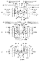
また、図4は車体フレーム2に取り付けられた各軸のサスペンション構造を示した正面図であり、この内、図4(a)は車体フレーム2に左右の前輪7,7を取り付けるための前軸の周辺構造を示した正面図、図4(b)は車体フレーム2に左右の中間輪8,8を取り付けるための中間軸の周辺構造を示した正面図、図4(c)は車体フレーム2に左右の後輪9,9を取り付けるための後軸の周辺構造を示した正面図である。
FIG. 2 is a perspective view showing the peripheral structure of the
Further, FIG. 4 is a front view showing the suspension structure of each axis attached to the
図2に示されるように、クレーン車1における車体フレーム2の主要部は、其の上面を覆う頂板10、および、其の側面を覆う左右の側板11,11によって構成される。
頂板10の略中央部には旋回体3を回転可能に取り付けるための円形状の旋回体設置孔12が設けられる一方、頂板10の後方部には、エンジンやトランスミッション等を設置するためのパワートレイン設置部13を形成するための間隙が、前後に長く画成されている。
パワートレイン設置部13に設置されるエンジンやトランスミッション等の設置に関しては公知であるので、ここでは特に説明しない。
また、車体フレーム2の下面側は適所に肉抜きを施した底板14によって図3に示されるようにして被覆され、頂板10と左右の側板11,11と底板14によって強固な応力外皮構造を有する車体フレーム2が形成されている。
As shown in FIG. 2, the main part of the
A circular
Since the installation of the engine, transmission, etc. installed in the power
Further, the lower surface side of the
図4(a)に示される通り、前輪7,7を支える前軸15は、デフケースを含むアクスルビーム16と其の左右に設けられたナックルアーム(車輪支持部)17,17等によって構成され、左右のナックルアーム17,17は、転舵の中心軸となるキングピン18,18を中心に、左右の操舵用油圧シリンダ19,19によってステアリングされるようになっている。
また、アクスルビーム16の移動はトルクロッド20とラテラルロッド41によって上下方向にのみ許容され、左右のナックルアーム17,17の操舵角度は、此れらを接続するタイロッド21によって同期される。
そして、前軸7を支える左右のサスペンションシリンダ22,22の各々の一端(上端)は、図2および図4(a)に示される通り、車体フレーム2の頂板10の上面よりも上方に突出して側方に延出する左右のサスペンションシリンダ取付ブラケット23,23を介して車体フレーム2に枢着される一方、これら左右のサスペンションシリンダ22,22の各々の他端(下端)は、各前輪7,7の転舵の中心軸に沿って左右のキングピン18,18の上端部に枢着されている。
図4(a)に示される通り、左右のサスペンションシリンダ22,22の各々の一端(上端)の枢着位置は、頂板10の上面高さと同等、もしくは、其れよりも僅かに高い。
As shown in FIG. 4A, the front shaft 15 that supports the
Further, the movement of the
Then, one end (upper end) of each of the left and right suspension cylinders 22 and 22 supporting the
As shown in FIG. 4A, the pivotal positions of one ends (upper ends) of the left and right suspension cylinders 22 and 22 are equal to or slightly higher than the height of the upper surface of the
アクスルビーム16に作用する曲げモーメントの大きさは、サスペンションシリンダ22の他端(下端)と此れに対応する前輪7との間の水平離間距離D1(モーメントの腕の長さ)に前軸15に作用する軸重の1/2を掛け合わせた値である。
従って、サスペンションシリンダ22の他端(下端)の取付位置をアクスルビーム16よりも外側に位置するキングピン18とし、水平離間距離D1の値を減らすことによって、アクスルビーム16の端部にサスペンションシリンダ22の他端(下端)を取り付けた場合に比べ、アクスルビーム16に作用する曲げモーメントを軽減してアクスルビーム16の実質的な耐久性を向上させることができる。
サスペンションシリンダ22の他端(下端)の取付位置をキングピン18とすることにより、アクスルビーム16の端部上面にサスペンションシリンダ22の他端(下端)を取り付けた場合と比較してサスペンションシリンダ22の他端(下端)の取付位置が上方に移動することになるが、サスペンションシリンダ22の一端(上端)の取付位置を規制するサスペンションシリンダ取付ブラケット23の側も車体フレーム2の頂板10の上面より上方に移動させているので、サスペンションシリンダ22の伸縮ストロークが保証される。
The magnitude of the bending moment acting on the
Therefore, the attachment position of the other end (lower end) of the suspension cylinder 22 is set to the kingpin 18 located outside the
By setting the mounting position of the other end (lower end) of the suspension cylinder 22 to the kingpin 18, the other side of the suspension cylinder 22 is compared with the case where the other end (lower end) of the suspension cylinder 22 is mounted on the upper surface of the end portion of the
また、図4(c)に示されるように、後輪9,9を支える後軸24は、デフケースを含むアクスルビーム25と其の左右に設けられたナックルアーム(車輪支持部)26,26等によって構成され、左右のナックルアーム26,26は、転舵の中心軸となるキングピン27,27を中心にステアリングされ、左右のナックルアーム26,26の操舵角度は、此れらを接続するタイロッド28によって同期されるようになっている。
前記と同様、アクスルビーム25の移動はトルクロッド42によって上下方向にのみ許容されている。
そして、後軸24を支える左右のサスペンションシリンダ29,29の各々の一端(上端)は、図2および図4(c)に示される通り、車体フレーム2の頂板10の上面よりも上方に突出して側方に延出する左右のサスペンションシリンダ取付ブラケット30,30を介して車体フレーム2に枢着される一方、此れら左右のサスペンションシリンダ29,29の各々の他端(下端)は、各後輪9,9の転舵の中心軸に沿って左右のキングピン27,27の上端部に枢着されている。
図4(c)に示される通り、左右のサスペンションシリンダ29,29の各々の一端(上端)の枢着位置は、頂板10の上面高さと同等、もしくは、其れよりも僅かに高く、前軸15のサスペンションシリンダ22,22の各々の一端(上端)の枢着位置の高さと同等である。
Further, as shown in FIG. 4 (c), the rear shaft 24 that supports the rear wheels 9 and 9 includes an
Similar to the above, the movement of the
Then, one end (upper end) of each of the left and
As shown in FIG. 4C, the pivotal positions of one ends (upper ends) of the left and
アクスルビーム25に作用する曲げモーメントの大きさは、サスペンションシリンダ29の他端(下端)と此れに対応する後輪9との間の水平離間距離D1’(モーメントの腕の長さ)に後軸24に作用する軸重の1/2を掛け合わせた値である。
従って、サスペンションシリンダ29の他端(下端)の取付位置をアクスルビーム25よりも外側に位置するキングピン27とし、水平離間距離D1’の値を減らすことによって、アクスルビーム25の端部にサスペンションシリンダ29の他端(下端)を取り付けた場合に比べ、アクスルビーム25に作用する曲げモーメントを軽減してアクスルビーム25の実質的な耐久性を向上させることができる。
サスペンションシリンダ29の他端(下端)の取付位置をキングピン27とすることにより、アクスルビーム25の端部上面にサスペンションシリンダ29の他端(下端)を取り付けた場合と比較してサスペンションシリンダ29の他端(下端)の取付位置が上方に移動することになるが、サスペンションシリンダ29の一端(上端)の取付位置を規制するサスペンションシリンダ取付ブラケット30の側も車体フレーム2の頂板10の上面より上方に移動させているので、サスペンションシリンダ29の伸縮ストロークが保証される。
The magnitude of the bending moment acting on the
Therefore, by setting the mounting position of the other end (lower end) of the
By setting the mounting position of the other end (lower end) of the
これに対し、図4(b)に示されるように、中間輪8,8を支える中間軸31は、アクスルビーム32と其の左右に設けられたナックルアーム(車輪支持部)33,33等によって構成され、左右のナックルアーム33,33は、転舵の中心軸となるキングピン34,34を中心にステアリングされ、左右のナックルアーム33,33の操舵角度は、此れらを接続するタイロッド35によって同期されるようになっている。
また、アクスルビーム32の移動はトルクロッド36とラテラルロッド37によって上下方向にのみ許容されている。
車体フレーム2の頂板10は、図3に示されるように、少なくとも、中間軸31を支える左右のサスペンションシリンダ38,38の各々の一端(上端)の取付箇所において左右の側板11,11を越えて側方に延出し、此の部分によって、サスペンションシリンダ取付部39,39となる張り出し部を形成している。
そして、中間軸31を支える左右のサスペンションシリンダ38,38の各々の一端(上端)は、図4(b)に示されるように、其の上端面40aがサスペンションシリンダ取付部39の下面に当接すると共に其の内側端面40bが側板11に当接し、且つ、其の外側端面40cが頂板10から側方に突出しない大きさの中間軸用サスペンションシリンダ取付ブラケット40,40を介して車体フレーム2の側面11,11に取り付けられている。
このように、車体フレーム2の頂板10と一体に形成されたサスペンションシリンダ取付部39の下面と車体フレーム2の側板11の双方に当接させて中間軸用サスペンションシリンダ取付ブラケット40を車体フレーム2に溶接等の手段で固着することにより、車体フレーム2の長手方向の中央寄りに位置する中間軸31を支える左右のサスペンションシリンダ38,38の一端(上端)を車体フレーム2の両側に強固に取り付けることができる。
また、サスペンション構造の構成要素の一種であるサスペンションシリンダ38,38や中間軸用サスペンションシリンダ取付ブラケット40が車体フレーム2の頂板10を越えて上方に突出することもなくなるので、旋回体3の回転時におけるサスペンション構造の構成要素と旋回体3との干渉が解消され、車体フレーム2に密接させて旋回体3を取り付けることが可能となって、クレーン車1の全高を低く抑えて走行安定性を確保することができる。
そして、図4(b)に示される通り、左右のサスペンションシリンダ38,38の各々の他端(下端)は、各中間輪8,8の転舵の中心軸であるキングピン34,34から内側にオフセットして、中間軸31のアクスルビーム32の左右の端部上面側に取り付けられている。
図4(b)に示される通り、左右のサスペンションシリンダ38,38の各々の一端(上端)の枢着位置は頂板10の下面側であり、従って、前軸15のサスペンションシリンダ22,22の各々の一端(上端)の枢着位置や後軸24のサスペンションシリンダ29,29の各々の一端(上端)の枢着位置に比べて取付位置の高さが低い。
On the other hand, as shown in FIG. 4B, the intermediate shaft 31 that supports the intermediate wheels 8 and 8 is provided by the axle beam 32 and the knuckle arms (wheel support portions) 33 and 33 provided on the left and right sides of the axle beam 32. The left and
Further, the movement of the axle beam 32 is permitted only in the vertical direction by the
As shown in FIG. 3, the
Then, as shown in FIG. 4B, one end (upper end) of each of the left and
In this way, the suspension
Further, since the
Then, as shown in FIG. 4B, the other ends (lower ends) of the left and
As shown in FIG. 4B, the pivotal position of one end (upper end) of each of the left and
また、中間軸31に作用する軸重は、前軸15に作用する軸重や後軸24に作用する軸重よりも軽くなるように設計されている。 Further, the axle load acting on the intermediate shaft 31 is designed to be lighter than the axle load acting on the front axle 15 and the axle load acting on the rear axle 24.
アクスルビーム32に作用する曲げモーメントの大きさは、サスペンションシリンダ38の他端(下端)と此れに対応する後輪8との間の水平離間距離D2(モーメントの腕の長さ)に中間軸31に作用する軸重の1/2を掛け合わせた値である。
この中間軸31に関しては、サスペンションシリンダ38の他端(下端)の取付位置をキングピン34よりも内側に位置するアクスルビーム32の端部としているので、モーメントの腕の長さとなる水平離間距離D2は前軸15の場合のD1や後軸24の場合のD1’に比べて長くなる。しかし、中間軸31に作用する軸重は前軸15に作用する軸重や後軸24に作用する軸重よりも軽くなるように設計されているので、中間軸31のアクスルビーム32に作用する曲げモーメントが過大となることはなく、例えば、アクスルビーム32に作用する曲げモーメントの大きさを前軸15や後軸24の場合と同等の範囲に収めることができる。
The magnitude of the bending moment acting on the axle beam 32 is the intermediate axis with the horizontal separation distance D2 (the length of the arm of the moment) between the other end (lower end) of the
Regarding this intermediate shaft 31, since the mounting position of the other end (lower end) of the
そして、このようにして前軸15や後軸24に加えて3軸目の中間軸31と其の中間輪8,8を設置することで、クレーン車1が取り扱いの対象とする吊荷の大型化に伴う車体の高重量化に対処することができるようになる。 Then, by installing the third intermediate shaft 31 and its intermediate wheels 8 and 8 in addition to the front shaft 15 and the rear shaft 24 in this way, the crane vehicle 1 handles a large suspended load. It will be possible to cope with the increase in weight of the vehicle body due to the increase in weight.
動力伝達系や操舵系の構成に関しては既に公知であるので特に説明しないが、この実施形態におけるクレーン車1においては、前軸15に取り付けられた前輪7,7と後軸24に取り付けられた後輪9,9の4つの車輪が駆動輪として機能し、前軸15に取り付けられた前輪7,7と中間軸31に取り付けられた中間輪8,8と後軸24に取り付けられた後輪9,9の全てが操舵輪として機能するようになっている。
そして、走行に際しては、通常、前軸15のみに駆動力を伝達し、また、前軸15と後軸24の双方に対して一定の割合で駆動力を分割して伝達することも可能である。
Since the configurations of the power transmission system and the steering system are already known, they will not be described in particular, but in the crane vehicle 1 in this embodiment, after being attached to the
Then, when traveling, it is usually possible to transmit the driving force only to the front axle 15 and to divide and transmit the driving force to both the front axle 15 and the rear axle 24 at a constant ratio. ..
この実施形態では、前軸15と後軸24に関しては、共に、車体フレーム2よりも上方に突出して側方に延出するサスペンションシリンダ取付ブラケット23,30を介してサスペンションシリンダ22,29の各々の一端(上端)を車体フレーム2に取り付ける一方、これらのサスペンションシリンダ22,29の各々の他端(下端)をキングピン18,26の上端部に取り付けるようにしているので、サスペンションシリンダ22の両端部に位置する枢着点間の離間距離とサスペンションシリンダ29の両端部に位置する枢着点間の離間距離とが等しい。
従って、前軸15のサスペンションシリンダ22と後軸24のサスペンションシリンダ29は同一仕様のものを利用することができ互換性がある。
In this embodiment, with respect to the front shaft 15 and the rear shaft 24, both of the
Therefore, the suspension cylinder 22 of the front shaft 15 and the
一方、中間軸31のサスペンションシリンダ38に関しては、其の他端(下端)をキングピン34の上端部よりも低い位置にあるアクスルビーム32の端部上面に取り付けるようにしているが、サスペンションシリンダ38の一端(上端)も頂板10の上面よりも低い位置にある車体フレーム2の側面に取り付けるようにしているので、結果的に、サスペンションシリンダ38の両端部に位置する枢着点間の離間距離とサスペンションシリンダ22,29の両端部に位置する各々の枢着点間の離間距離とは等しくなり、中間軸31のサスペンションシリンダ38と前軸15のサスペンションシリンダ22と後軸24のサスペンションシリンダ29は同一仕様のものを利用することができる。
このように、サスペンションシリンダ22,29,38の長さに関連する仕様つまり枢着点間の離間距離を同一化することにより、各軸に共通する同一仕様のサスペンションシリンダの使用が可能となって、生産工程での部品管理が容易化される。
また、此れらの仕様が同一であるため、結果的に、サスペンションシリンダ22,29,38の各々を前軸15,中間軸31,後軸24の何れに取り付けても問題が生じることはなく、組立工程で生じる可能性のあるサスペンションシリンダの組み違いも防止されることになる。
On the other hand, regarding the
In this way, by making the specifications related to the lengths of the
Further, since these specifications are the same, as a result, no problem occurs even if each of the
以上の実施形態では、一例として、3軸6輪のクレーン車1に本発明のサスペンション装置を適用した場合について説明したが、本発明のサスペンション装置は総車軸数が3を超えるクレーン車にも適用できる。
総車軸数が3を超えるクレーン車の場合にあっては、クレーン車の最も前方に位置する軸が前軸、また、最も後方に位置する軸が後軸であって、それ以外の軸は全て中間軸である。
また、総車軸数が3以上のクレーン車において、どの軸を駆動輪とするか、および、どの軸を操舵連とするかは設計上の問題である。
In the above embodiment, as an example, the case where the suspension device of the present invention is applied to the crane vehicle 1 having 3 axles and 6 wheels has been described, but the suspension device of the present invention is also applied to the crane vehicle having a total number of axles exceeding 3. it can.
In the case of a crane vehicle with a total number of axles exceeding 3, the frontmost axis of the crane vehicle is the front axle, the rearmost axle is the rear axle, and all other axles are It is an intermediate axis.
Further, in a crane vehicle having a total number of axles of 3 or more, which axis is used as a driving wheel and which axis is used as a steering chain is a design problem.
本発明は、クレーン車などを初め、車体フレーム上に旋回体を備えた総車軸数3以上の自走式作業機に適用することができる。 The present invention can be applied to self-propelled work machines having a total number of axles of 3 or more and having a swivel body on a vehicle body frame, such as a crane vehicle.
1 クレーン車
2 車体フレーム
3 旋回体
4 ブーム
5 キャビン
6 アウトリガー
7 前輪
8 中間輪
9 後輪
10 頂板
11 側板
12 旋回体設置孔
13 パワートレイン設置部
14 底板
15 前軸
16 アクスルビーム
17 ナックルアーム(車輪支持部)
18 キングピン
19 操舵用油圧シリンダ
20 トルクロッド
21 タイロッド
22 サスペンションシリンダ
23 サスペンションシリンダ取付ブラケット
24 後軸
25 アクスルビーム
26 ナックルアーム(車輪支持部)
27 キングピン
28 タイロッド
29 サスペンションシリンダ
30 サスペンションシリンダ取付ブラケット
31 中間軸
32 アクスルビーム
33 ナックルアーム(車輪支持部)
34 キングピン
35 タイロッド
36 トルクロッド
37 ラテラルロッド
38 サスペンションシリンダ
39 サスペンションシリンダ取付部(頂板の張り出し部)
40 中間軸用サスペンションシリンダ取付ブラケット
40a 中間軸用サスペンションシリンダ取付ブラケットの上端面
40b 中間軸用サスペンションシリンダ取付ブラケットの内側端面
40c 中間軸用サスペンションシリンダ取付ブラケットの外側端面
41 ラテラルロッド
42 トルクロッド
1
18
27
34
40 Suspension cylinder mounting bracket for intermediate shaft 40a Upper end surface of suspension cylinder mounting bracket for intermediate shaft 40b Inner end surface of suspension cylinder mounting bracket for
Claims (3)
前記前軸を支える左右のサスペンションシリンダと前記後軸を支える左右のサスペンションシリンダの各々の一端が、前記車体フレームよりも上方に突出して側方に延出する左右のサスペンションシリンダ取付ブラケットを介して前記車体フレームに取り付けられる一方、これら左右のサスペンションシリンダの各々の他端が各輪の転舵の中心軸に沿って左右のキングピンの上端部に取り付けられると共に、
前記中間軸を支える左右のサスペンションシリンダの各々の一端が、前記車体フレームの側面に取り付けられる一方、これら左右のサスペンションシリンダの各々の他端が各輪の転舵の中心軸から内側にオフセットして前記中間軸のアクスルビームの左右の端部に取り付けられ、
前記車体フレームが、其の上面を覆う頂板、および、其の側面を覆う左右の側板を備えると共に、前記頂板が、前記中間軸を支える左右のサスペンションシリンダの各々の一端の取付箇所で前記左右の側板を越えて側方に延出してサスペンションシリンダ取付部を形成し、
前記中間軸を支える左右のサスペンションシリンダの各々の前記一端が、其の上端面が前記サスペンションシリンダ取付部の下面に当接すると共に其の内側端面が前記左右の側板に当接し且つ其の外側端面が前記頂板から側方に突出しない大きさの中間軸用サスペンションシリンダ取付ブラケットを介して前記車体フレームの側面に取り付けられていることを特徴とする自走式作業機のサスペンション構造。 A suspension structure for a self-propelled work machine having a total number of axles of 3 or more, in which a swinging body is provided on a vehicle body frame and one or more intermediate axles are arranged between the front axle and the rear axle.
The left and right suspension cylinders that support the front axle and one ends of the left and right suspension cylinders that support the rear axle project via the left and right suspension cylinder mounting brackets that project upward from the vehicle body frame and extend laterally. While attached to the body frame, the other ends of each of these left and right suspension cylinders are attached to the upper ends of the left and right kingpins along the central axis of the steering of each wheel.
One end of each of the left and right suspension cylinders supporting the intermediate shaft is attached to the side surface of the vehicle body frame, while the other end of each of the left and right suspension cylinders is offset inward from the central axis of steering of each wheel. Attached to the left and right ends of the axle beam of the intermediate axis ,
The vehicle body frame includes a top plate covering the upper surface thereof and left and right side plates covering the side surfaces thereof, and the top plates are left and right at mounting points at one ends of the left and right suspension cylinders supporting the intermediate shaft. A suspension cylinder mounting part is formed by extending laterally beyond the side plate.
The upper end surface of each of the left and right suspension cylinders supporting the intermediate shaft abuts on the lower surface of the suspension cylinder mounting portion, the inner end surface thereof abuts on the left and right side plates, and the outer end surface thereof abuts. A suspension structure of a self-propelled work machine, which is mounted on a side surface of the vehicle body frame via a suspension cylinder mounting bracket for an intermediate shaft having a size that does not project laterally from the top plate.
Priority Applications (1)
| Application Number | Priority Date | Filing Date | Title |
|---|---|---|---|
| JP2016014185A JP6764656B2 (en) | 2016-01-28 | 2016-01-28 | Suspension device for work equipment |
Applications Claiming Priority (1)
| Application Number | Priority Date | Filing Date | Title |
|---|---|---|---|
| JP2016014185A JP6764656B2 (en) | 2016-01-28 | 2016-01-28 | Suspension device for work equipment |
Publications (2)
| Publication Number | Publication Date |
|---|---|
| JP2017132365A JP2017132365A (en) | 2017-08-03 |
| JP6764656B2 true JP6764656B2 (en) | 2020-10-07 |
Family
ID=59502134
Family Applications (1)
| Application Number | Title | Priority Date | Filing Date |
|---|---|---|---|
| JP2016014185A Active JP6764656B2 (en) | 2016-01-28 | 2016-01-28 | Suspension device for work equipment |
Country Status (1)
| Country | Link |
|---|---|
| JP (1) | JP6764656B2 (en) |
-
2016
- 2016-01-28 JP JP2016014185A patent/JP6764656B2/en active Active
Also Published As
| Publication number | Publication date |
|---|---|
| JP2017132365A (en) | 2017-08-03 |
Similar Documents
| Publication | Publication Date | Title |
|---|---|---|
| CN104925153B (en) | Caterpillar | |
| JP6157638B2 (en) | Steering intermediate arm | |
| RU2652515C2 (en) | Device for providing pivotal motion between a tandem or crawler axle and a vehicle body and also a relevant method | |
| CN105163961A (en) | Suspension device for in-wheel motor driven wheel | |
| US20050280241A1 (en) | Suspended, articulated and powered front axle for work vehicle | |
| CN106218782A (en) | A kind of supporting construction of falling three-wheel | |
| CN206812741U (en) | The double yoke suspensions of electric automobile | |
| JP5828235B2 (en) | Railcar steering wheel | |
| RU2487018C2 (en) | Stabiliser system for wheel axle suspension, and stabiliser | |
| CN106314644A (en) | Reversible tricycle | |
| CN104191925A (en) | Non-driven independent suspension axle and all-terrain crane | |
| CN205440525U (en) | Large -scale electric drive tipper front axle positioner | |
| CN105835947A (en) | Multi-axis synchronous steering system for automobile underpan | |
| CN206187211U (en) | Reverse tricycle | |
| JP6764656B2 (en) | Suspension device for work equipment | |
| WO2018010799A1 (en) | Vehicle with steerable driven rear axle | |
| EP2907734B1 (en) | Front suspension of a vehicle | |
| CN106515837A (en) | Steering system of construction vehicle and crane applying steering system | |
| JP4857658B2 (en) | Suspension device | |
| JP5291954B2 (en) | Wheel crane | |
| CN110816668A (en) | Articulated cross-country crane chassis | |
| JP5056235B2 (en) | Suspension device for auxiliary steering wheel for vehicle | |
| JP6764694B2 (en) | Wheel crane body frame | |
| CN211032740U (en) | Articulated cross-country crane chassis | |
| JP3881853B2 (en) | Frame structure of traveling body and crane provided with the same |
Legal Events
| Date | Code | Title | Description |
|---|---|---|---|
| A621 | Written request for application examination |
Free format text: JAPANESE INTERMEDIATE CODE: A621 Effective date: 20190122 |
|
| A977 | Report on retrieval |
Free format text: JAPANESE INTERMEDIATE CODE: A971007 Effective date: 20191206 |
|
| A131 | Notification of reasons for refusal |
Free format text: JAPANESE INTERMEDIATE CODE: A131 Effective date: 20200107 |
|
| A521 | Request for written amendment filed |
Free format text: JAPANESE INTERMEDIATE CODE: A523 Effective date: 20200306 |
|
| TRDD | Decision of grant or rejection written | ||
| A01 | Written decision to grant a patent or to grant a registration (utility model) |
Free format text: JAPANESE INTERMEDIATE CODE: A01 Effective date: 20200908 |
|
| A61 | First payment of annual fees (during grant procedure) |
Free format text: JAPANESE INTERMEDIATE CODE: A61 Effective date: 20200914 |
|
| R150 | Certificate of patent or registration of utility model |
Ref document number: 6764656 Country of ref document: JP Free format text: JAPANESE INTERMEDIATE CODE: R150 |
|
| R250 | Receipt of annual fees |
Free format text: JAPANESE INTERMEDIATE CODE: R250 |